Embed Size (px)
Citation preview

KEN_TOOLINGSYSTEMS11_D000_D001.qxp:WIDIA 10:45 AM Page D2

D1www.kennametal.com
BTKV and CVKV Shank Tools
BTKV40 . . . . . . . . . . . . . . . . . . . . . . . . . . . . . . . . . . . . . . . . . . . . . . . . . . . . . . . . . . . . . . . . . . . . . . . . . . . . . . .D2–D19
BTKV50 . . . . . . . . . . . . . . . . . . . . . . . . . . . . . . . . . . . . . . . . . . . . . . . . . . . . . . . . . . . . . . . . . . . . . . . . . . . . . .D20–D37
CVKV40 . . . . . . . . . . . . . . . . . . . . . . . . . . . . . . . . . . . . . . . . . . . . . . . . . . . . . . . . . . . . . . . . . . . . . . . . . . . . . .D38–D51
CVKV50 . . . . . . . . . . . . . . . . . . . . . . . . . . . . . . . . . . . . . . . . . . . . . . . . . . . . . . . . . . . . . . . . . . . . . . . . . . . . . .D52–D67
KEN_TOOLINGSYSTEMS11_D000_D001.qxp:WIDIA 10:45 AM Page D1

D2 www.kennametal.com
ERICKSON™ Taper Face Contact Shank Tooling System • BTKV40 Series
Primary ApplicationERICKSON Taper Face BT Contact Taper Tooling is manufactured from premium materials and to the latest JIS B 6339 specification standard with an AT3 7/24 Taper per IS0-1974. Controlled, increased flange thickness to the rear of the flange gains face contact between spindle and holder. The BTKV40 tools are prebalanced to a high specification that will perform effectively up to 20,000 RPM. For any applications higher than 20,000 RPM, Kennametal recommends that the complete toolholder assembly (toolholder, retention knobs, collets, hardware, and cutting tools) be balanced as one identity.
Features and Benefits
• JIS B 6339 7/24 taper.
• Standard M16 metric drawbar thread.
• High axial repeatability due to face contact.
• High radial positioning due to controlled, tighter drive key widths.
• All tools set to form AD coolant specification. Many can be converted to form B style.
• Maximum 20,000 RPM.
• Maximum 100 bar (1,500 psi) coolant pressure.
Tool changer V-groove.
Large chamfer lead-in.
2 controlled drive key widths.
Face contact.
Metric drawbar.
7/24 taper.
KEN_TOOLINGSYSTEMS11_D002_D003.qxp:WIDIA 10:45 AM Page D2

D3www.kennametal.com
BTKVShank Style
40ShankTaperSize
BSpecial Feature
(optional)
TGToolholder
Style
50Toolholder
Size
How Do Catalog Numbers Work?Each character in our catalog number signifies a specific trait of thatproduct. Use the following key columns and corresponding imagesto easily identify which attributes apply.
MIdentification
Value
B =DIN form B coolant feature, tool shipped to ADspecification (design allows conversion to form B style)
(blank) =(no “B” or “Z”) — tool built to form A/AD coolant style
HPV =High performance andbalanceable
TD =Tunable
TG =Collet series xx (50), xxx (100)
EM =I.D. size: metric — xx = xx, (20);
inch — xxx = x.xx, (075)
SM =O.D. size: metric — xx = xx, (20);
inch — xxx = x.xx, (075)
JIS B6339Face Contact
40 = 40
50 = 50
M =Tool built to metric values and hasmetric retention thread
BB = Bar blank
EM = End mill adapter
ER = DIN 6499 single-angle collet chuck
KM = KM™ adapter
SM2C = Shell mill adapter with coolant and small diameter
SMC = Shell mill adapter with coolant
TG = Tremendous Grip single-angle collet chuck
TT = Shrink Fit thermo toolholder
TTHT = Shrink Fit thermo toolholder — high torque
100Tool
Length
(Gage lineon taper tofront of tool)
inchxxx = x.xx
BTKV Face Contact Shank ToolsCatalog Numbering System
BTKV40BTG50100M
KEN_TOOLINGSYSTEMS11_D002_D003.qxp:WIDIA 10:45 AM Page D3

D4 www.kennametal.com
order number catalog number D1 D2 D21 L1 L1FC L2 L9 Vstop
screwwrench sizestop screw kg
3854807 BTKV40BHPVTT06090M 6 21 27 90 89,0 63,0 26 10 TTSS05014M 2,5mm 1,17
3854808 BTKV40BHPVTT08090M 8 21 27 90 89,0 63,0 26 10 TTSS06014M 3mm 1,16
3854809 BTKV40BHPVTT10090M 10 24 32 90 89,0 63,0 31 10 TTSS08014M 4mm 1,22
3854810 BTKV40BHPVTT12090M 12 24 32 90 89,0 63,0 36 10 TTSS10014M 5mm 1,21
3854811 BTKV40BHPVTT14090M 14 27 34 90 89,0 63,0 36 10 TTSS10014M 5mm 1,26
3854812 BTKV40BHPVTT16090M 16 27 34 90 89,0 63,0 39 10 TTSS12014M 6mm 1,24
3854823 BTKV40BHPVTT18090M 18 33 41 90 89,0 63,0 39 10 TTSS12014M 6mm 1,38
3854824 BTKV40BHPVTT20090M 20 33 41 90 89,0 63,0 41 10 TTSS16014M 8mm 1,35
3854825 BTKV40BHPVTT25100M 25 44 52 100 99,0 73,0 47 10 TTSS16014M 8mm 1,76
3854826 BTKV40BHPVTT32105M 32 44 53 105 104,0 78,0 51 10 TTSS16014M 8mm 1,67
Cutting Tool Shank Requirements
metric (ISO standard)
cutting tool
shank diameter tolerance
6 h6 0,000/-0,008
8 & 10 h6 0,000/-0,009
12, 14, 16, & 18 h6 0,000/-0,011
20 & 25 h6 0,000/-0,013
32 h6 0,000/-0,016
BTKV40 Shank Tools
• Balanceable — fine tune with optional M6 set screws.
• Suitable for carbide and HSS cutting tools (requirements below).
L1FC = from flange face
L1 = from taper gage diameter
� TT GP HPV MM-BTKV Form B/AD
(continued)
Shrink Fit Toolholders General Purpose (GP)
BT
KV
40 S
ha
nk
To
ols
KEN_TOOLINGSYSTEMS11_D004_D005.qxp:WIDIA 10:45 AM Page D4

BT
KV
40 S
ha
nk
To
ols
D5www.kennametal.com
order number catalog number D1 D2 D21 L1 L1FC L2 L9 Vstop
screwwrench sizestop screw lbs
3861327 BTKV40BHPVTT025350 1/4 .83 1.06 3.50 3.46 2.44 1.02 .39 TTSS05014M 2,5mm 2.56
3861328 BTKV40BHPVTT031350 5/16 .83 1.06 3.50 3.46 2.44 1.02 .39 TTSS06014M 3mm 2.55
3861329 BTKV40BHPVTT038350 3/8 .94 1.26 3.50 3.46 2.44 1.22 .39 TTSS08014M 4mm 2.68
3861330 BTKV40BHPVTT044350 7/16 .94 1.26 3.50 3.46 2.44 1.42 .39 TTSS10014M 5mm 2.66
3861331 BTKV40BHPVTT050350 1/2 .94 1.26 3.50 3.46 2.44 1.42 .39 TTSS10014M 5mm 2.64
3861332 BTKV40BHPVTT062350 5/8 1.06 1.33 3.50 3.46 2.44 1.54 .39 TTSS12014M 6mm 2.71
3861343 BTKV40BHPVTT075400 3/4 1.30 1.65 4.00 3.96 2.94 1.61 .39 TTSS16014M 8mm 3.26
3861344 BTKV40BHPVTT088400 7/8 1.30 1.65 4.00 3.96 2.94 1.61 .39 TTSS16014M 8mm 3.18
3861345 BTKV40BHPVTT100400 1 1.73 2.06 4.00 3.96 2.94 1.85 .39 TTSS16014M 8mm 3.91
3861346 BTKV40BHPVTT125425 1 1/4 1.73 2.08 4.25 4.21 3.19 2.01 .39 TTSS16014M 8mm 3.81
Cutting Tool Shank Requirements
inch (industry standard)
cutting tool
shank diameters tolerance
1/4, 5/16, & 3/8 .0000/-.0004
7/16, 1/2, & 5/8 .0000/-.0004
3/4, 7/8, 1, & 1-1/4 .0000/-.0005
BTKV40 Shank ToolsShrink Fit Toolholders General Purpose (GP)
� TT HPV IN-BTKV Form B/AD
(TT GP HPV BTKV Form B/AD continued)
NOTE: Do not overheat. Overheating will destroy the accuracy and functionality of the toolholder.Shrink Fit technical section, see page M78.Supplied with stop screw.Adjusting stop screw gage, see page M81.Optional M6~1.0P x 5mm lg fine-balancing screw set (10 pieces) is available. Order number is MS1276PKG and must be ordered separately.For retention knobs, see page L45.For Shrink Fit machine and accessories, see pages L12–L13.
KEN_TOOLINGSYSTEMS11_D004_D005.qxp:WIDIA 10:45 AM Page D5

D6 www.kennametal.com
order number catalog number D1 D2 D21 L1 L1FC L2 L9 Vstop
screwwrench sizestop screw kg
3854827 BTKV40BHPVTTHT12090M 12 24 32 90,0 89,0 63 36 10 TTSS10014M 5mm 1,21
3854828 BTKV40BHPVTTHT14090M 14 27 34 90,0 89,0 63 36 10 TTSS10014M 5mm 1,26
3854829 BTKV40BHPVTTHT16090M 16 27 34 90,0 89,0 63 39 10 TTSS12014M 6mm 1,24
3854830 BTKV40BHPVTTHT18090M 18 33 41 90,0 89,0 63 39 10 TTSS12014M 6mm 1,38
3854831 BTKV40BHPVTTHT20090M 20 33 41 90,0 89,0 63 41 10 TTSS16014M 8mm 1,35
3854832 BTKV40BHPVTTHT25100M 25 44 52 100,0 99,0 73 47 10 TTSS16014M 8mm 1,76
3854833 BTKV40BHPVTTHT32105M 32 44 53 105,0 104,0 78 51 10 TTSS16014M 8mm 1,67
Cutting Tool Shank Requirements
metric (ISO standard)
cutting tool
shank diameter tolerance
12, 14, 16, & 18 h6 0,000/-0,011
20 & 25 h6 0,000/-0,013
32 h6 0,000/-0,016
BTKV40 Shank ToolsShrink Fit Toolholders High Torque (HT)
• 30–50% higher clamping torque compared to GP line.
• Balanceable — fine tune with optional M6 set screws.
• Suitable for carbide only, designated bygroove in front face (requirements below).
• 10 kW power or greater Shrink Fit device must be used.
L1FC = from flange face
L1 = from taper gage diameter
� TT HT HPV MM-BTKV Form B/AD
(continued)
BT
KV
40 S
ha
nk
To
ols
KEN_TOOLINGSYSTEMS11_D006_D007.qxp:WIDIA 10:45 AM Page D6

D7www.kennametal.com
order number catalog number D1 D2 D21 L1 L1FC L2 L9 Vstop
screwwrench sizestop screw lbs
3861347 BTKV40BHPVTTHT050350 1/2 .94 1.26 3.50 3.46 2.44 1.42 .39 TTSS10014M 5mm 2.64
3861348 BTKV40BHPVTTHT062350 5/8 1.06 1.33 3.50 3.46 2.44 1.54 .39 TTSS12014M 6mm 2.71
3861349 BTKV40BHPVTTHT075400 3/4 1.30 1.65 4.00 3.96 2.94 1.61 .39 TTSS16014M 8mm 3.26
3861350 BTKV40BHPVTTHT088400 7/8 1.30 1.65 4.00 3.96 2.94 1.61 .39 TTSS16014M 8mm 3.17
3861351 BTKV40BHPVTTHT100400 1 1.73 2.06 4.00 3.96 2.94 1.85 .39 TTSS16014M 8mm 3.91
3861352 BTKV40BHPVTTHT125425 1 1/4 1.73 2.08 4.25 4.21 3.19 2.01 .39 TTSS16014M 8mm 3.81
Cutting Tool Shank Requirements
inch (industry standard)
cutting tool
shank diameters tolerance
1/2 & 5/8 .0000/-.0004
3/4, 7/8, 1, & 1-1/4 .0000/-.0005
BTKV40 Shank ToolsShrink Fit Toolholders High Torque (HT)
� TT HT HPV IN-BTKV Form B/AD
(TT HT HPV BTKV Form B/AD continued)
NOTE: Do not overheat. Overheating will destroy the accuracy and functionality of the toolholder.Shrink Fit technical section, see page M78.Supplied with stop screw.Adjusting stop screw gage, see page M81.Optional M6~1.0P x 5mm lg fine-balancing screw set (10 pieces) is available. Order number is MS1276PKG and must be ordered separately.For retention knobs, see page L45.For Shrink Fit machine and accessories, see pages L12–L13.
BT
KV
40 S
ha
nk
To
ols
KEN_TOOLINGSYSTEMS11_D006_D007.qxp:WIDIA 10:45 AM Page D7

D8 www.kennametal.com
order number catalog numbercolletseries D11 L1 L1FC L9 V locknut wrench Nm
stop screw
wrench sizestop screw kg
3856650 BTKV40BTG075070M TG75 50 70,0 69,0 50 10 LNA075M HSW45M 136 SS081041G 4mm & 5/32 1,24
3856651 BTKV40BTG100080M TG100 60 80,0 79,0 64 10 LNA100M HSW58M 203 SS112041G 4mm & 5/32 1,43
3856652 BTKV40BTG100100M TG100 60 100,0 99,0 64 14 LNA100M HSW58M 203 SS112041G 4mm & 5/32 1,71
3856663 BTKV40BTG100150M TG100 60 150,0 149,0 64 64 LNA100M HSW58M 203 SS112041G 4mm & 5/32 2,19
3856664 BTKV40BTG150110M TG150 85 110,0 109,0 78 15 LNA150M HSW80M 271 SS112041G 4mm & 5/32 2,40
BTKV40 Shank ToolsTG Single-Angle Collet Chucks
• Tremendous Grip (3:1 advantage).
L1FC = from flange face
L1 = from taper gage diameter
collet series
� TG Round-BTKV Form B/AD
Collet Capacity
mm inch
TG collet series min max min max
TG75 2,6 20,0 3/64 3/4
TG100 2,6 25,5 5/64 1
TG150 11,6 40,0 23/64 1 1/2
NOTE: Collet must be loaded into locknut first. Before loading into the chuck body, insert the cutting tool, then tighten to the recommended tightening torque.Collet chuck technical section, see page M98.Supplied with locknut and stop screw.Locknut wrench must be ordered separately.Interchangeable locknuts, coolant-style locknuts, and coolant disks are available and must be ordered separately; see page L19.Stop screw coolant caps are available and must be ordered separately; see pages L34–L35.Balanceable/interchangeable locknuts are available and must be ordered separately; see page L16.TG standard straight-bore collets, see page J10.TG tap collets, see page J10.For retention knobs, see page L45.
BT
KV
40 S
ha
nk
To
ols
KEN_TOOLINGSYSTEMS11_D008_D009.qxp:WIDIA 11:26 AM Page D8

Experience the advantages at your Authorized Kennametal Distributor or at www.kennametal.com.
www.kennametal.com
ERICKSON™ & KM™
• Most accurate chuck, ≤3μm (.0001"), achieves maximum performance from your cutting edge.
• Inherent dampening design extends tool life and improves surface finish.
• Pre-balanced to high specifications.
• Versatile as a collet chuck with the use of reduction sleeves.
For hydraulic chucks — ERICKSON and KM — the industry names you can trust.
Names You Can Trust
KEN_TOOLINGSYSTEMS11_D008_D009.qxp:WIDIA 11:26 AM Page D9

D10 www.kennametal.com
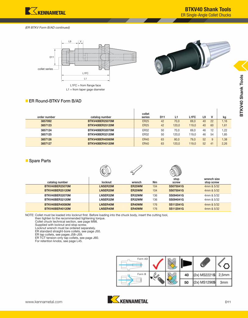
BTKV40 Shank ToolsER Single-Angle Collet Chucks
Collet Capacity
mm inch
ER collet series min max min max
ER16 0,5 10,0 .02 .41
ER20 0,5 13,0 .02 .50
ER25 1,0 16,0 .04 .63
ER32 2,0 20,0 .08 .81
ER40 3,0 26,0 .12 1.00
order number catalog numbercolletseries D11 L1 L1FC L9 V kg
3857088 BTKV40BER16060M ER16 28 60,0 59,0 32 32 1,04
3857089 BTKV40BER16120M ER16 28 120,0 119,0 32 48 1,29
3857090 BTKV40BER20060M ER20 34 60,0 59,0 36 27 1,04
3857091 BTKV40BER20120M ER20 34 120,0 119,0 36 64 1,42
catalog number locknut wrenchcounterbore collet
torque (Nm)straight collettorque (Nm)
stop screw
wrench sizestop screw
BTKV40BER16060M LNHSER16M OEW25M 40 56 SS044038G 4mm & 5/32
BTKV40BER16120M LNHSER16M OEW25M 40 56 SS044038G 4mm & 5/32
BTKV40BER20060M LNHSER20M OEW30M 32 80 SS056041G 4mm & 5/32
BTKV40BER20120M LNHSER20M OEW30M 32 80 SS056041G 4mm & 5/32
• Grip (2:1 advantage).
collet series
L1FC = from flange face
L1 = from taper gage diameter
� ER Hex-BTKV Form B/AD
� Spare Parts
(continued)
BT
KV
40 S
ha
nk
To
ols
KEN_TOOLINGSYSTEMS11_D010_D011.qxp:WIDIA 10:46 AM Page D10
D11www.kennametal.com
BTKV40 Shank ToolsER Single-Angle Collet Chucks
order number catalog numbercolletseries D11 L1 L1FC L9 V kg
3857092 BTKV40BER25070M ER25 42 70,0 69,0 40 22 1,16
3857123 BTKV40BER25120M ER25 42 120,0 119,0 40 60 1,61
3857124 BTKV40BER32070M ER32 50 70,0 69,0 46 12 1,22
3857125 BTKV40BER32120M ER32 50 120,0 119,0 46 54 1,85
3857126 BTKV40BER40080M ER40 63 80,0 79,0 52 9 1,38
3857127 BTKV40BER40120M ER40 63 120,0 119,0 52 41 2,26
collet series
L1FC = from flange face
L1 = from taper gage diameter
� Spare Parts
� ER Round-BTKV Form B/AD
(ER BTKV Form B/AD continued)
catalog number locknut wrench Nmstop
screwwrench sizestop screw
BTKV40BER25070M LNSER25M ER25WM 104 SS075041G 4mm & 5/32
BTKV40BER25120M LNSER25M ER25WM 104 SS075041G 4mm & 5/32
BTKV40BER32070M LNSER32M ER32WM 136 SS094041G 4mm & 5/32
BTKV40BER32120M LNSER32M ER32WM 136 SS094041G 4mm & 5/32
BTKV40BER40080M LNSER40M ER40WM 176 SS112041G 4mm & 5/32
BTKV40BER40120M LNSER40M ER40WM 176 SS112041G 4mm & 5/32
NOTE: Collet must be loaded into locknut first. Before loading into the chuck body, insert the cutting tool, then tighten to the recommended tightening torque.Collet chuck technical section, see page M98.Supplied with locknut and stop screw.Locknut wrench must be ordered separately.ER standard straight-bore collets, see page J50.ER tap collets, see pages J58–J59.ER TCT tension-only tap collets, see page J60.For retention knobs, see page L45.
BT
KV
40 S
ha
nk
To
ols
KEN_TOOLINGSYSTEMS11_D010_D011.qxp:WIDIA 10:46 AM Page D11

D12 www.kennametal.com
order number catalog number D1 D2 L1 L1FC L9lock
screwwrench sizelock screw Nm kg
3856578 BTKV40BEM06050M 6 25 50,0 49,0 84 SS03M012 3mm 7 1,01
3856579 BTKV40BEM08050M 8 28 50,0 49,0 84 SS03M014 4mm 15 1,03
3856580 BTKV40BEM10063M 10 35 63,0 62,0 97 SS03M018 5mm 25 1,16
3856581 BTKV40BEM12063M 12 42 63,0 62,0 97 SS03M023 6mm 35 1,25
3856582 BTKV40BEM14063M 14 44 63,0 62,0 97 SS03M023 6mm 35 1,28
3856583 BTKV40BEM16063M 16 48 63,0 62,0 53 SS03M025 6mm 50 1,33
3856584 BTKV40BEM18063M 18 50 63,0 62,0 53 SS03M025 6mm 50 1,35
3856585 BTKV40BEM20063M 20 52 63,0 62,0 55 SS03M026 8mm 95 1,36
3856586 BTKV40BEM25090M 25 63 90,0 89,0 60 SS03M027 10mm 135 2,16
BTKV40 Shank ToolsEnd Mill Adapters
L1FC = from flange face
L1 = from taper gage diameter
� EM MM-BTKV Form B/AD
(continued)
BT
KV
40 S
ha
nk
To
ols
KEN_TOOLINGSYSTEMS11_D012_D013.qxp:WIDIA 10:46 AM Page D12

D13www.kennametal.com
order number catalog number D1 D2 L1 L1FC L9lock
screwwrench sizelock screw ft. lbs. lbs
3856587 BTKV40BEM025250 1/4 1.00 2.50 2.46 3.85 ELS025025PKG 1/8 5 2.35
3856588 BTKV40BEM031250 5/16 1.00 2.50 2.46 3.85 ELS031031PKG 5/32 11 2.31
3856589 BTKV40BEM038250 3/8 1.00 2.50 2.46 3.85 ELS038031PKG 3/16 15 2.32
3856590 BTKV40BEM050300 1/2 1.38 3.00 2.96 4.35 ELS044038PKG 7/32 20 2.69
3856591 BTKV40BEM062300 5/8 1.63 3.00 2.96 2.09 ELS056050PKG 1/4 40 2.93
3856592 BTKV40BEM075400 3/4 1.75 4.00 3.96 2.22 ELS062050PKG 5/16 70 3.62
3856593 BTKV40BEM088400 7/8 2.00 4.00 3.96 2.22 ELS062050PKG 5/16 70 4.11
3856594 BTKV40BEM100400 1 2.00 4.00 3.96 2.56 ELS075056PKG 3/8 110 3.95
3856595 BTKV40BEM125400 1 1/4 2.50 4.00 3.96 2.51 ELS075062PKG 3/8 110 4.81
L1FC = from flange face
L1 = from taper gage diameter
� EM IN-BTKV Form B/AD
BTKV40 Shank ToolsEnd Mill Adapters
(EM BTKV Form B/AD continued)
NOTE: Do not overtighten clamp screw; use torque recommendations above.Supplied with clamp screw.Clamp screw wrench not included.For retention knobs, see page L45.
BT
KV
40 S
ha
nk
To
ols
KEN_TOOLINGSYSTEMS11_D012_D013.qxp:WIDIA 10:46 AM Page D13

D14 www.kennametal.com
BTKV40 Shank ToolsTunable Shell Mill Adapters with Through Coolant
� SMC TD Lock MM-BTKV Form B/AD
L1FC = from flange face
L1 = from taper gage diameter
order number catalog number D1 D2 D21 L1 L1FC L2 L20 L21lock
screwdrive key
wrench sizelock screw kg
4136287 BTKV40BTDSMC22260M 22 49 60 260 259 13,5 216,8 233 MS1234 KDK22M 8mm 5,07
� SMC TD Cap MM-BTKV Form B/AD
order number catalog number D1 D2 L1 L1FC L2lock
screwdrive key
wrench sizelock screw kg
4136288 BTKV40BTDSMC27260M 27 61 260,0 259,0 233 KLSS27M — 10mm 5,98
L1FC = from flange faceL1 = from taper gage diameter
(continued)
BT
KV
40 S
hank
To
ols
KEN_TOOLINGSYSTEMS11_D014_D015.qxp:WIDIA 1:37 PM Page D14

D15
� SMC TD Lock IN-BTKV Form B/AD
L1FC = from flange faceL1 = from taper gage diameter
order number catalog number D1 D2 D21 L1 L1FC L2 L20 L21lock
screwdrive key
wrench sizelock screw lbs
4136289 BTKV40BTDSMC0751050 3/4 1.750 2.362 10.500 10.460 .53 8.797 9.437 KLS07 KDK05 1/4 10.694136290 BTKV40BTDSMC1001050 1 2.189 — 10.500 10.460 9.44 — — KLS10 KDK06 5/16 11.84
BTKV40 Shank ToolsTunable Shell Mill Adapters with Through Coolant
NOTE: Do not overtighten lock screw.Supplied with lock screw and drive keys.Interchangeable coolant-style lock screws are available and must be ordered separately; see page L38.Lock screw wrench not included.For retention knob, see page L45.
www.kennametal.com
(SMC TD BTKV Form B/AD continued)
BT
KV
40 S
hank
To
ols
KEN_TOOLINGSYSTEMS11_D014_D015.qxp:WIDIA 1:37 PM Page D15

D16 www.kennametal.com
order number catalog number D1 D2 L1 L1FClock
screwdrive key
wrench sizelock screw kg
3857109 BTKV40BSM2C16050M 16 38 50,0 49,0 MS1294 KDK16M 6mm 1,17
3857108 BTKV40BSMC16050M 16 44 50,0 49,0 MS1294 KDK16M 6mm 1,24
3857111 BTKV40BSM2C22055M 22 42 55,0 54,0 MS1234 — 8mm 1,31
3857110 BTKV40BSMC22055M 22 49 55,0 54,0 MS1234 KDK22M 8mm 1,42
L1FC = from flange face
L1 = from taper gage diameter
� SMC Cap MM-BTKV Form B/AD
(continued)
order number catalog number D1 D2 L1 L1FClock
screwdrive key
wrench sizelock screw kg
3857112 BTKV40BSMC27055M 27 60 55,0 54,0 KLSS27M KDK27M 10mm 1,68
3857163 BTKV40BSMC32060M 32 78 60,0 59,0 KLSS32M KDK32M 14mm 2,23
L1FC = from flange face
L1 = from taper gage diameter
� SMC Lock MM-BTKV Form B/AD
BTKV40 Shank ToolsShell Mill Adapters with Through Coolant
BT
KV
40 S
ha
nk
To
ols
KEN_TOOLINGSYSTEMS11_D016_D017.qxp:WIDIA 10:46 AM Page D16

D17www.kennametal.com
order number catalog number D1 D2 L1 L1FClock
screwdrive key
wrench sizelock screw lbs
3857166 BTKV40BSM2C050175 1/2 1.20 1.75 1.71 KLS05 KDK04 3/16 2.37
3857165 BTKV40BSMC050175 1/2 1.44 1.75 1.71 KLS05 KDK04 3/16 2.42
3857168 BTKV40BSM2C075200 3/4 1.46 2.00 1.96 KLS07 — 1/4 2.59
3857167 BTKV40BSMC075200 3/4 1.75 2.00 1.96 KLS07 KDK05 1/4 2.79
3857170 BTKV40BSM2C100200 1 2.19 2.00 1.96 KLS10 KDK06 5/16 3.25
3857169 BTKV40BSMC100200 1 2.75 2.00 1.96 KLS10 KDK06 5/16 3.71
3857171 BTKV40BSMC125200 1 1/4 2.88 2.00 1.96 KLS12 KDK08 5/16 4.05
3857172 BTKV40BSMC150200 1 1/2 3.81 2.00 1.96 KLS15 KDK10 3/8 5.39
L1FC = from flange face
L1 = from taper gage diameter
� SMC TD Lock IN-BTKV Form B/AD
(SMC BTKV Form B/AD continued)
BTKV40 Shank ToolsShell Mill Adapters with Through Coolant
NOTE: Do not overtighten lock screw.Supplied with lock screw and drive keys.Interchangeable coolant-style lock screws are available and must be ordered separately; see page L38.Lock screw wrench not included.For retention knobs, see page L45.
BT
KV
40 S
ha
nk
To
ols
KEN_TOOLINGSYSTEMS11_D016_D017.qxp:WIDIA 10:46 AM Page D17

D18 www.kennametal.com
L1FC = from flange face
L1 = from taper gage diameter
system size
order number catalog numbersystem
size D2 L1 L1FCKM spare
parts packagewrench size
actuation screw Nm kg
3822963 BTKV40BKM32050M KM32 32 50,0 49,0 KM32PKG3S 5mm 8-11 1,06
3822964 BTKV40BKM32090M KM32 32 90,0 89,0 KM32PKG3S 5mm 8-11 1,28
3822965 BTKV40BKM40055M KM40 40 55,0 54,0 KM40PKG3S 6mm 12-16 1,15
3822966 BTKV40BKM40100M KM40 40 100,0 99,0 KM40PKG3S 6mm 12-16 1,54
3822967 BTKV40BKM50065M KM50 50 65,0 64,0 KM50PKG3S 10mm 27-34 1,34
3822968 BTKV40BKM50120M KM50 50 120,0 119,0 KM50PKG3S 10mm 27-34 2,13
BTKV40 Shank ToolsKM™ Modular Adapters
� KM-BTKV Form B/AD
NOTE: Do not overtorque actuation screw; use torque recommendations above.Supplied with KM actuation mechanism.For retention knobs, see page L45.
BT
KV
40 S
ha
nk
To
ols
KEN_TOOLINGSYSTEMS11_D018_D019.qxp:WIDIA 10:46 AM Page D18

D19www.kennametal.com
order number catalog number D2 L1 L1FC kg
3815352 BTKV40BB063280M 63,0 280,0 279,0 7,13
3815363 BTKV40BB104200M 104,0 200,0 199,0 11,78
• Machinable front 20–30 RW C.
L1FC = from flange face
L1 = from taper gage diameter
� BB-BTKV Form A
BTKV40 Shank ToolsBar Blanks
NOTE: For retention knobs, see page L45.
BT
KV
40 S
ha
nk
To
ols
KEN_TOOLINGSYSTEMS11_D018_D019.qxp:WIDIA 10:46 AM Page D19

Primary ApplicationERICKSON Taper Face BT Contact Taper Tooling is manufactured from premium materials and to the latest JIS B 6339 specification standard. Controlled, increased flange thickness to the rear of the flange gains face contact between spindle and holder.The BTKV50 tools are prebalanced to a high specification that will perform effectively up to 20,000 RPM. For any applications higher than 20,000 RPM, Kennametal recommends that the complete toolholder assembly (toolholder, retention knobs, collets, hardware, and cutting tools) be balanced as one identity.
ERICKSON™ Taper Face Contact Shank Tooling System • BTKV50 Series
D20 www.kennametal.com
Tool changer V-groove.
Large chamfer lead-in.
2 controlled drive key widths.
Face contact.
Metric drawbar.
7/24 taper.
KEN_TOOLINGSYSTEMS11_D020_D021.qxp:WIDIA 10:46 AM Page D20

Features and Benefits
• JIS B 6339 7/24 taper.
• Standard M24 metric drawbar thread.
• High axial repeatability due to face contact.
• High radial positioning due to controlled, tighter drive key widths.
• All tools set to form AD coolant specification. Many can be converted to form B style.
• Maximum 20,000 RPM.
• Maximum 100 bar (1,500 psi) coolant pressure.
D21www.kennametal.com
KEN_TOOLINGSYSTEMS11_D020_D021.qxp:WIDIA 10:46 AM Page D21

D22 www.kennametal.com
BTKV50 Shank ToolsShrink Fit Toolholders General Purpose (GP)
order number catalog number D1 D2 D21 L1 L1FC L2 L9 Vstop
screwwrench sizestop screw kg
3856633 BTKV50BHPVTT06100M 6 21 27 100 98,5 62,0 26 10 TTSS05014M 2,5mm 3,72
3856634 BTKV50BHPVTT08100M 8 21 27 100 98,5 62,0 26 10 TTSS06014M 3mm 3,72
3856635 BTKV50BHPVTT10100M 10 24 32 100 98,5 62,0 31 10 TTSS08014M 4mm 3,78
3856636 BTKV50BHPVTT12100M 12 24 32 100 98,5 62,0 36 10 TTSS10014M 5mm 3,76
3856637 BTKV50BHPVTT14100M 14 27 34 100 98,5 62,0 36 10 TTSS10014M 5mm 3,81
3856638 BTKV50BHPVTT16100M 16 27 34 100 98,5 62,0 39 10 TTSS12014M 6mm 3,79
3856639 BTKV50BHPVTT18100M 18 33 41 100 98,5 62,0 39 10 TTSS12014M 6mm 3,93
3856640 BTKV50BHPVTT20100M 20 33 41 100 98,5 62,0 41 10 TTSS16014M 8mm 3,90
3856641 BTKV50BHPVTT25100M 25 44 52 100 98,5 62,0 47 10 TTSS16014M 8mm 4,19
3856642 BTKV50BHPVTT32100M 32 44 52 100 98,5 62,0 51 10 TTSS16014M 8mm 4,03
Cutting Tool Shank Requirements
metric (ISO standard)
cutting tool
shank diameter tolerance
6 h6 0,000/-0,008
8 & 10 h6 0,000/-0,009
12, 14, 16, & 18 h6 0,000/-0,011
20 & 25 h6 0,000/-0,013
32 h6 0,000/-0,016
• Balanceable — fine tune with optional M6 set screws.
• Suitable for carbide and HSS cutting tools (requirements below).
L1FC = from flange face
L1 = from taper gage diameter
� TT GP HPV MM-BTKV Form B/AD
(continued)
BT
KV
50 S
ha
nk
To
ols
KEN_TOOLINGSYSTEMS11_D022_D023.qxp:WIDIA 10:46 AM Page D22
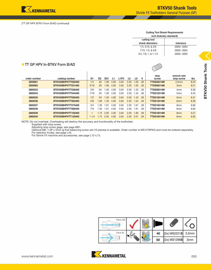
D23www.kennametal.com
order number catalog number D1 D2 D21 L1 L1FC L2 L9 Vstop
screwwrench sizestop screw lbs
3859981 BTKV50BHPVTT025400 1/4 .83 1.06 4.00 3.94 2.50 1.02 .39 TTSS05014M 2,5mm 8.23
3859982 BTKV50BHPVTT031400 5/16 .83 1.06 4.00 3.94 2.50 1.02 .39 TTSS06014M 3mm 8.21
3860033 BTKV50BHPVTT038400 3/8 .94 1.26 4.00 3.94 2.50 1.22 .39 TTSS08014M 4mm 8.36
3860034 BTKV50BHPVTT044400 7/16 .94 1.26 4.00 3.94 2.50 1.42 .39 TTSS10014M 5mm 8.33
3860035 BTKV50BHPVTT050400 1/2 .94 1.26 4.00 3.94 2.50 1.42 .39 TTSS10014M 5mm 8.31
3860036 BTKV50BHPVTT062400 5/8 1.06 1.33 4.00 3.94 2.50 1.54 .39 TTSS12014M 6mm 8.38
3860037 BTKV50BHPVTT075400 3/4 1.30 1.61 4.00 3.94 2.50 1.61 .39 TTSS16014M 8mm 8.66
3860038 BTKV50BHPVTT088400 7/8 1.30 1.61 4.00 3.94 2.50 1.61 .39 TTSS16014M 8mm 8.60
3860039 BTKV50BHPVTT100400 1 1.73 2.05 4.00 3.94 2.50 1.85 .39 TTSS16014M 8mm 9.27
3860040 BTKV50BHPVTT125400 1 1/4 1.73 2.05 4.00 3.94 2.50 2.01 .39 TTSS16014M 8mm 8.95
Cutting Tool Shank Requirements
inch (industry standard)
cutting tool
shank diameters tolerance
1/4, 5/16, & 3/8 .0000/-.0004
7/16, 1/2, & 5/8 .0000/-.0004
3/4, 7/8, 1, & 1-1/4 .0000/-.0005
� TT GP HPV In-BTKV Form B/AD
BTKV50 Shank ToolsShrink Fit Toolholders General Purpose (GP)
(TT GP HPV BTKV Form B/AD continued)
BT
KV
50 S
ha
nk
To
ols
NOTE: Do not overheat. Overheating will destroy the accuracy and functionality of the toolholder.Supplied with stop screw.Adjusting stop screw gage, see page M81.Optional M6~1.0P x 5mm lg fine-balancing screw set (10 pieces) is available. Order number is MS1276PKG and must be ordered separately.For retention knobs, see page L45.For Shrink Fit machine and accessories, see page L12–L13.
KEN_TOOLINGSYSTEMS11_D022_D023.qxp:WIDIA 10:46 AM Page D23

D24 www.kennametal.com
order number catalog number D1 D2 D21 L1 L1FC L2 L9 Vstop
screwwrench sizestop screw kg
3856643 BTKV50BHPVTTHT12100M 12 24 32 100 98,5 62,0 36 10 TTSS10014M 5mm 3,76
3856644 BTKV50BHPVTTHT14100M 14 27 34 100 98,5 62,0 36 10 TTSS10014M 5mm 3,81
3856645 BTKV50BHPVTTHT16100M 16 27 34 100 98,5 62,0 39 10 TTSS12014M 6mm 3,79
3856646 BTKV50BHPVTTHT18100M 18 33 41 100 98,5 62,0 39 10 TTSS12014M 6mm 3,93
3856647 BTKV50BHPVTTHT20100M 20 33 41 100 98,5 62,0 41 10 TTSS16014M 8mm 3,90
3856648 BTKV50BHPVTTHT25100M 25 44 52 100 98,5 62,0 47 10 TTSS16014M 8mm 4,90
3856649 BTKV50BHPVTTHT32100M 32 44 52 100 98,5 62,0 51 10 TTSS16014M 8mm 4,03
Cutting Tool Shank Requirements
metric (ISO standard)
cutting tool
shank diameter tolerance
12, 14, 16, & 18 h6 0,000/-0,011
20 & 25 h6 0,000/-0,013
32 h6 0,000/-0,016
BTKV50 Shank ToolsShrink Fit Toolholders High Torque (HT)
• 30–50% higher clamping torque compared to GP line.
• Balanceable — fine tune with optional M6 set screws.
• Suitable for carbide only, designated bygroove in front face (requirements below).
• 10 kW power or greater Shrink Fit device must be used.
L1FC = from flange face
L1 = from taper gage diameter
� TT HT HPV MM-BTKV Form B/AD
(continued)
BT
KV
50 S
ha
nk
To
ols
KEN_TOOLINGSYSTEMS11_D024_D025.qxp:WIDIA 10:46 AM Page D24

D25www.kennametal.com
order number catalog number D1 D2 D21 L1 L1FC L2 L9 Vstop
screwwrench sizestop screw lbs
3860041 BTKV50BHPVTTHT050400 1/2 .94 1.26 4.00 3.94 2.504 1.42 .39 TTSS10014M 5mm 8.31
3860042 BTKV50BHPVTTHT062400 5/8 1.06 1.33 4.00 3.94 2.504 1.54 .39 TTSS12014M 6mm 8.38
3860043 BTKV50BHPVTTHT075400 3/4 1.30 1.61 4.00 3.94 2.504 1.61 .39 TTSS16014M 8mm 8.66
3860044 BTKV50BHPVTTHT088400 7/8 1.30 1.61 4.00 3.94 2.504 1.61 .39 TTSS16014M 8mm 8.60
3860045 BTKV50BHPVTTHT100400 1 1.73 2.05 4.00 3.94 2.504 1.85 .39 TTSS16014M 8mm 9.27
3860046 BTKV50BHPVTTHT125400 1 1/4 1.73 2.05 4.00 3.94 2.504 2.01 .39 TTSS16014M 8mm 8.95
Cutting Tool Shank Requirements
inch (industry standard)
cutting tool
shank diameters tolerance
1/2 & 5/8 .0000/-.0004
3/4, 7/8, 1, & 1-1/4 .0000/-.0005
� TT HT HPV In-BTKV Form B/AD
(TT HT HPV BTKV Form B/AD continued)
BTKV50 Shank ToolsShrink Fit Toolholders High Torque (HT)
BT
KV
50 S
ha
nk
To
ols
NOTE: Do not overheat. Overheating will destroy the accuracy and functionality of the toolholder.Shrink Fit technical section, see page M78.Supplied with stop screw.Adjusting stop screw gage, see page M81.Optional M6~1.0P x 5mm lg fine-balancing screw set (10 pieces) is available. Order number is MS1276PKG and must be ordered separately.For retention knobs, see page L45.For Shrink Fit machine and accessories, see pages L12–L13.
KEN_TOOLINGSYSTEMS11_D024_D025.qxp:WIDIA 10:46 AM Page D25

D26 www.kennametal.com
BT
KV
50 S
ha
nk
To
ols
order number catalog numbercolletseries D11 L1 L1FC L9 V locknut wrench
stop screw
wrench sizestop screw Nm kg
3856665 BTKV50BTG100090M TG100 60 90,0 88,5 64 36 LNA100M HSW58M SS112041G 4mm & 5/32 203 3,97
3856666 BTKV50BTG100150M TG100 60 150,0 148,5 64 89 LNA100M HSW58M SS112041G 4mm & 5/32 203 5,15
3856667 BTKV50BTG150100M TG150 85 100,0 98,5 78 13 LNA150M HSW80M SS162062G 4mm & 5/32 271 4,43
3856668 BTKV50BTG150150M TG150 85 150,0 148,5 78 49 LNA150M HSW80M SS162062G 4mm & 5/32 271 6,08
Collet Capacity
mm inch
TG collet series min max min max
TG100 2,6 25,5 5/64 1
TG150 11,6 40,0 23/64 1-1/2
BTK50 Shank ToolsTG Single-Angle Collet Chucks
L1FC = from flange face
L1 = from taper gage diameter
� TG Round-BTKV Form B/AD
collet series
NOTE: Collet must be loaded into locknut first. Before loading into the chuck body, insert the cutting tool, then tighten to the recommended tightening torque.Collet chuck technical section, see page M98.Supplied with locknut and stop screw.Locknut wrench must be ordered separately.Interchangeable locknuts, coolant-style locknuts, and coolant disks are available and must be ordered separately; see pages L16–L17.Stop screw coolant caps are available and must be ordered separately; see pages L34–L35.Balanceable/interchangeable locknuts are available and must be ordered separately; see page L16.TG standard straight-bore collets, see page J10.TG tap collets, see page J10.For retention knobs, see page L45.
KEN_TOOLINGSYSTEMS11_D026_D027.qxp:WIDIA 10:46 AM Page D26

Experience the advantages at your Authorized Kennametal Distributor or at www.kennametal.com.
To BEATthe HEAT
• HP drill point — prevents workpiece flexing.
• Straight cut edge — rigid corner wedge withstands high thermal and mechanical stress.
• Unique flute design — improves chip evacuation.
• K715™ grade — specified, uncoated 9% Co fine-grain carbide.
• Customization — intermediate diameters, length variations, and step drills available as customized solutions.
• For the latest product catalog, please refer to the e-catalog at www.kennametal.com.
B/K284 Solid Carbide DrillsB/K284 Series Solid Carbide Drills offer a material-specific design and grade for machining
high-temperature-resistant alloys, like titanium and nickel-based alloys, in aerospace
applications. This drill minimizes subsurface deformation.
www.kennametal.com
KEN_TOOLINGSYSTEMS11_D026_D027.qxp:WIDIA 10:46 AM Page D27

D28 www.kennametal.com
BT
KV
50 S
ha
nk
To
ols
• Grip (2:1 advantage).
L1FC = from flange face
L1 = from taper gage diameterCollet Capacity
mm inch
ER collet series min max min max
ER16 0,5 10,0 .02 .41
ER20 0,5 13,0 .02 .50
ER25 1,0 16,0 .04 .63
ER32 2,0 20,0 .08 .81
ER40 3,0 26,0 .12 1.00
order number catalog numbercolletseries D11 L1 L1FC L9 V kg
3857128 BTKV50BER16100M ER16 28 100 98,5 32 48 3,78
3857129 BTKV50BER16150M ER16 28 150 148,5 32 48 3,97
3857130 BTKV50BER20070M ER20 34 70 68,5 36 24 3,65
3857131 BTKV50BER20150M ER20 34 150 148,5 36 64 4,12
catalog number locknut wrenchcounterbore collet
torque (Nm)straight collettorque (Nm)
stop screw
wrench sizestop screw
BTKV50BER16100M LNHSER16M OEW25M 40 56 SS044038G 4mm & 5/32
BTKV50BER16150M LNHSER16M OEW25M 40 56 SS044038G 4mm & 5/32
BTKV50BER20070M LNHSER20M OEW30M 32 80 SS056041G 4mm & 5/32
BTKV50BER20150M LNHSER20M OEW30M 32 80 SS056041G 4mm & 5/32
� Spare Parts
(continued)
BTKV50 Shank ToolsER Single-Angle Collet Chucks
order number catalog numbercolletseries D11 L1 L1FC L9 V kg
3857128 BTKV50BER16100M ER16 28 100 98,5 32 48 3,78
3857129 BTKV50BER16150M ER16 28 150 148,5 32 48 3,97
3857130 BTKV50BER20070M ER20 34 70 68,5 36 24 3,65
3857131 BTKV50BER20150M ER20 34 150 148,5 36 64 4,12
� ER Hex-BTKV Form B/AD
collet series
KEN_TOOLINGSYSTEMS11_D028_D029.qxp:WIDIA 10:46 AM Page D28

BT
KV
50 S
ha
nk
To
ols
D29www.kennametal.com
order number catalog numbercolletseries D11 L1 L1FC L9 V kg
3857132 BTKV50BER25070M ER25 42 70,0 68,5 40 40 3,69
3857133 BTKV50BER25150M ER25 42 150,0 148,5 40 60 4,38
3857134 BTKV50BER32070M ER32 50 70,0 68,5 46 38 3,67
3857135 BTKV50BER32150M ER32 50 150,0 148,5 46 54 4,67
3857136 BTKV50BER40080M ER40 63 80,0 78,5 52 38 3,83
3857137 BTKV50BER40150M ER40 63 150,0 148,5 52 48 5,33
BTKV50 Shank ToolsER Single-Angle Collet Chucks
collet series
L1FC = from flange face
L1 = from taper gage diameter
� ER Round-BTKV Form B/AD
� Spare Parts
(ER BTKV Form B/AD continued)
catalog number locknut wrench Nmstop
screwwrench sizestop screw
BTKV50BER25070M LNSER25M ER25WM 104 SS075041G 4mm & 5/32
BTKV50BER25150M LNSER25M ER25WM 104 SS075041G 4mm & 5/32
BTKV50BER32070M LNSER32M ER32WM 136 SS094041G 4mm & 5/32
BTKV50BER32150M LNSER32M ER32WM 136 SS094041G 4mm & 5/32
BTKV50BER40080M LNSER40M ER40WM 176 SS112041G 4mm & 5/32
BTKV50BER40150M LNSER40M ER40WM 176 SS112041G 4mm & 5/32
NOTE: Collet must be loaded into locknut first. Before loading into the chuck body, insert the cutting tool, then tighten to the recommended tightening torque.Collet chuck technical section, see page M98.Supplied with locknut and stop screw.Locknut wrench must be ordered separately.ER standard straight-bore collets, see page J50.ER tap collets, see pages J58–J59.ER TCT tension-only tap collets, see page J60.For retention knobs, see page L45.
KEN_TOOLINGSYSTEMS11_D028_D029.qxp:WIDIA 10:46 AM Page D29

D30 www.kennametal.com
L1FC = from flange face
L1 = from taper gage diameter
BTKV50 Shank ToolsEnd Mill Adapters
(continued)
order number catalog number D1 D2 L1 L1FClock
screwwrench sizelock screw Nm kg
3856539 BTKV50BEM06063M 6 24,5 63,0 61,5 SS03M012 3mm 7 3,58
3856541 BTKV50BEM08063M 8 27,5 63,0 61,5 SS03M014 4mm 15 3,60
3856542 BTKV50BEM10080M 10 34,5 80,0 78,5 SS03M018 5mm 25 3,79
3856563 BTKV50BEM12080M 12 41,5 80,0 78,5 SS03M023 6mm 35 3,86
3856564 BTKV50BEM14080M 14 43,5 80,0 78,5 SS03M023 6mm 35 3,90
3856565 BTKV50BEM16080M 16 47,5 80,0 78,5 SS03M025 6mm 50 3,97
3856566 BTKV50BEM18080M 18 49,5 80,0 78,5 SS03M025 6mm 50 4,00
3856567 BTKV50BEM20080M 20 51,5 80,0 78,5 SS03M026 8mm 95 4,02
3856568 BTKV50BEM25105M 25 64,5 105,0 103,5 SS03M027 10mm 135 4,80
3856569 BTKV50BEM32105M 32 71,5 105,0 103,5 SS03M029 10mm 160 5,04
3856570 BTKV50BEM40120M 40 89,5 120,0 118,5 SS03M029 10mm 160 6,56
3856571 BTKV50BEM50130M 50 99,5 130,0 128,5 — 12mm 200 7,50
� EM MM-BTKV Form B/AD
BT
KV
50 S
ha
nk
To
ols
KEN_TOOLINGSYSTEMS11_D030_D031.qxp:WIDIA 10:47 AM Page D30

D31www.kennametal.com
BTKV50 Shank ToolsEnd Mill Adapters
order number catalog number D1 D2 L1 L1FClock
screwwrench sizelock screw ft. lbs. lbs
3856572 BTKV50BEM050300 1/2 1.37 3.00 2.94 ELS044038PKG 7/32 20 8.18
3856573 BTKV50BEM075400 3/4 1.75 4.00 3.94 ELS062050PKG 5/16 70 8.99
3856574 BTKV50BEM100400 1 2.00 4.00 3.94 ELS075056PKG 3/8 110 8.95
3856575 BTKV50BEM125400 1 1/4 2.50 4.00 3.94 ELS075062PKG 3/8 110 10.08
3856576 BTKV50BEM150450 1 1/2 2.75 4.50 4.44 ELS075069PKG 3/8 110 11.05
3856577 BTKV50BEM200550 2 3.75 5.50 5.44 ELS100088PKG 1/2 148 16.28
� EM IN-BTKV Form B/AD
L1FC = from flange face
L1 = from taper gage diameter
(EM BTKV Form B/AD continued)
NOTE: Do not overtighten clamp screw; use torque recommendations above.Supplied with clamp screw.Clamp screw wrench not included.For retention knobs, see page L45.
BT
KV
50 S
ha
nk
To
ols
KEN_TOOLINGSYSTEMS11_D030_D031.qxp:WIDIA 10:47 AM Page D31

D32 www.kennametal.com
BT
KV
50 S
hank
To
ols
BTKV50 Shank ToolsTunable Shell Mill Adapters with Through Coolant
order number catalog number D1 D2 D21 L1 L1FC L2 L20 L21lock
screwdrive key
wrench sizelock screw kg
4136291 BTKV50BTDSMC22260M 22 49 70 260,0 258,5 13,5 211,8 222 MS1234 KDK22M 8mm 8,27
order number catalog number D1 D2 D21 L1 L1FC L2 L20 L21lock
screwdrive key
wrench sizelock screw kg
4136292 BTKV50BTDSMC27320M 27 61 80 320 318,5 13,5 271,8 282 KLSS27M — 10mm 11,894136303 BTKV50BTDSMC32330M 32 78 — 330 328,5 292,0 — — KLSS32M KDK32M 14mm 16,22
L1FC = from flange face
L1 = from taper gage diameter
� SMC TD Cap MM-BTKV Form B/AD
� SMC TD Lock MM-BTKV Form B/AD
L1FC = from flange face
L1 = from taper gage diameter
(continued)
KEN_TOOLINGSYSTEMS11_D032_D033.qxp:WIDIA 2:26 PM Page D32

D33www.kennametal.com
BT
KV
50 S
hank
To
ols
BTKV50 Shank ToolsTunable Shell Mill Adapters with Through Coolant
order number catalog number D1 D2 D21 L1 L1FC L2 L20 L21lock
screwdrive key
wrench sizelock screw lbs
4136304 BTKV50BTDSMC0751050 3/4 1.75 2.56 10.50 10.44 .53 8.60 9.00 KLS07 KDK05 1/4 16.864136305 BTKV50BTDSMC1001250 1 2.75 — 12.50 12.44 11.00 — — KLS10 KDK06 5/16 25.60
4136306 BTKV50BTDSMC1251300 1 1/4 2.88 — 13.00 12.94 11.50 — — KLS12 KDK08 5/16 32.85
L1FC = from flange face
L1 = from taper gage diameter
� SMC TD Lock IN-BTKV Form B/AD
NOTE: Do not overtighten lock screw.Supplied with lock screw and drive keys.Interchangeable coolant-style lock screws are available and must be ordered separately; see page L38.Lock screw wrench not included.For retention knobs, see page L45.
(SMC continued)
KEN_TOOLINGSYSTEMS11_D032_D033.qxp:WIDIA 2:26 PM Page D33

D34 www.kennametal.com
BTKV50 Shank ToolsShell Mill Adapters with Through Coolant
L1FC = from flange face
L1 = from taper gage diameter
order number catalog number D1 D2 L1 L1FClock
screwdrive key
wrench sizelock screw kg
3857069 BTKV50BSM2C16045M 16 38 45,0 43,5 MS1294 KDK16M 6mm 3,66
3857068 BTKV50BSMC16045M 16 44 45,0 43,5 MS1294 KDK16M 6mm 3,67
3857071 BTKV50BSM2C22045M 22 42 45,0 43,5 MS1234 — 8mm 3,66
3857070 BTKV50BSMC22045M 22 49 45,0 43,5 MS1234 KDK22M 8mm 3,69
� SMC Cap MM-BTKV Form B/AD
L1FC = from flange face
L1 = from taper gage diameter
order number catalog number D1 D2 D4 G1 L1 L1FClock
screwdrive key
wrench sizelock screw kg
3857072 BTKV50BSMC27045M 27 60 — — 45,0 43,5 KLSS27M KDK27M 10mm 3,80
3857093 BTKV50BSMC32045M 32 78 — — 45,0 43,5 KLSS32M KDK32M 14mm 4,01
3857094 BTKV50BSMC40050M 40 89 66,7 M12X1.75 50,0 48,5 KLSS40M KDK40M 17mm 4,46
3857095 BTKV50BSMC60090M 60 129 101,6 M16X2.0 90,0 88,5 — KDK60M — 8,55
� SMC Lock MM-BTKV Form B/AD
(continued)
BT
KV
50 S
ha
nk
To
ols
KEN_TOOLINGSYSTEMS11_D034_D035.qxp:WIDIA 10:47 AM Page D34

D35www.kennametal.com
L1FC = from flange face
L1 = from taper gage diameter
order number catalog number D1 D2 D4 G1 L1 L1FClock
screwdrive key
wrench sizelock screw lbs
3857102 BTKV50BSMC200300 2 4.88 4.00 5/8-11 UNC 3.00 2.94 KLS20 KDK12 9/16 15.08
3857103 BTKV50BSMC250300 2 1/2 4.88 4.00 5/8-11 UNC 3.00 2.94 KLS25 KDK16 9/16 16.33
� SMC Lock IN-BTKV Form B/AD
(SMC Lock BTKV Form B/AD continued)
BTKV50 Shank ToolsShell Mill Adapters with Through Coolant
order number catalog number D1 D2 L1 L1FClock
screwdrive key
wrench sizelock screw lbs
3857097 BTKV50BSM2C075200 3/4 1.46 2.00 1.941 KLS07 — 1/4 8.14
3857096 BTKV50BSMC075200 3/4 1.75 2.00 1.941 KLS07 KDK05 1/4 8.25
3857099 BTKV50BSM2C100200 1 2.19 2.00 1.941 KLS10 KDK06 5/16 8.45
3857098 BTKV50BSMC100200 1 2.75 2.00 1.941 KLS10 KDK06 5/16 8.75
3857100 BTKV50BSMC125200 1 1/4 2.88 2.00 1.941 KLS12 KDK08 5/16 9.05
3857101 BTKV50BSMC150200 1 1/2 3.81 2.00 1.941 KLS15 KDK10 3/8 10.07
� SMC Lock MM-BTKV Form B/AD
L1FC = from flange face
L1 = from taper gage diameter
NOTE: Do not overtighten lock screw.Supplied with lock screw and drive keys.Interchangeable coolant-style lock screws are availableand must be ordered separately; see page L38.Lock screw wrench not included.For retention knob, see page L45.
BT
KV
50 S
ha
nk
To
ols
KEN_TOOLINGSYSTEMS11_D034_D035.qxp:WIDIA 10:47 AM Page D35
D36 www.kennametal.com
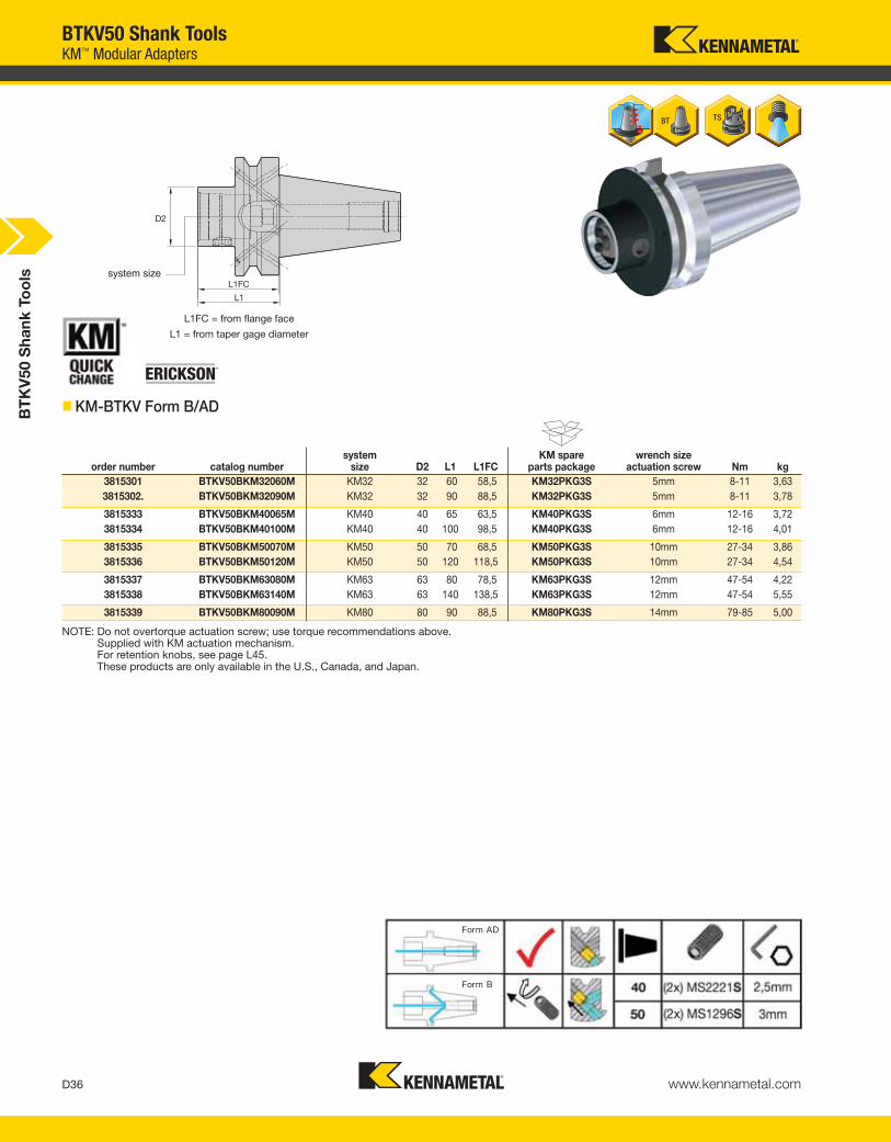
BTKV50 Shank ToolsKM™ Modular Adapters
L1FC = from flange face
L1 = from taper gage diameter
system size
� KM-BTKV Form B/AD
order number catalog numbersystem
size D2 L1 L1FCKM spare
parts packagewrench size
actuation screw Nm kg
3815301 BTKV50BKM32060M KM32 32 60 58,5 KM32PKG3S 5mm 8-11 3,63
3815302. BTKV50BKM32090M KM32 32 90 88,5 KM32PKG3S 5mm 8-11 3,78
3815333 BTKV50BKM40065M KM40 40 65 63,5 KM40PKG3S 6mm 12-16 3,72
3815334 BTKV50BKM40100M KM40 40 100 98,5 KM40PKG3S 6mm 12-16 4,01
3815335 BTKV50BKM50070M KM50 50 70 68,5 KM50PKG3S 10mm 27-34 3,86
3815336 BTKV50BKM50120M KM50 50 120 118,5 KM50PKG3S 10mm 27-34 4,54
3815337 BTKV50BKM63080M KM63 63 80 78,5 KM63PKG3S 12mm 47-54 4,22
3815338 BTKV50BKM63140M KM63 63 140 138,5 KM63PKG3S 12mm 47-54 5,55
3815339 BTKV50BKM80090M KM80 80 90 88,5 KM80PKG3S 14mm 79-85 5,00
BT
KV
50 S
ha
nk
To
ols
NOTE: Do not overtorque actuation screw; use torque recommendations above.Supplied with KM actuation mechanism.For retention knobs, see page L45.These products are only available in the U.S., Canada, and Japan.
KEN_TOOLINGSYSTEMS11_D036_D037.qxp:WIDIA 10:47 AM Page D36
D37www.kennametal.com
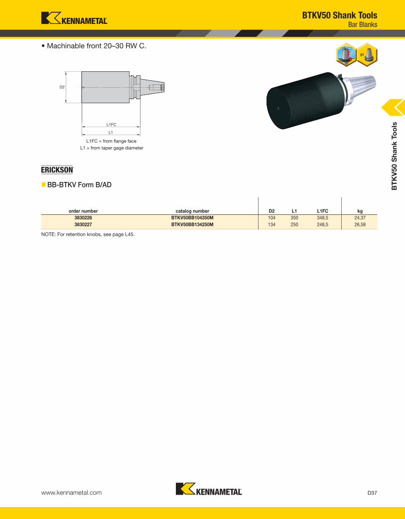
order number catalog number D2 L1 L1FC kg
3830226 BTKV50BB104350M 104 350 348,5 24,37
3830227 BTKV50BB134250M 134 250 248,5 26,58
• Machinable front 20–30 RW C.
L1FC = from flange face
L1 = from taper gage diameter
� BB-BTKV Form B/AD
BTKV50 Shank ToolsBar Blanks
BT
KV
50 S
ha
nk
To
ols
NOTE: For retention knobs, see page L45.
KEN_TOOLINGSYSTEMS11_D036_D037.qxp:WIDIA 10:47 AM Page D37

D38 www.kennametal.com
ERICKSON™ Taper Face Contact Shank Tooling System • CVKV40 Series
Primary ApplicationERICKSON Taper Face CV Contact Taper Tooling is manufactured from premium materials and to the latest ANSI B5.50 specification standard. Controlled, increased flange thickness to the rear of the flange gains face contact between spindle and holder. The CVKV40 tools are prebalanced to a high specification that will perform effectively up to 20,000 RPM. For any applications higher than 20,000 RPM, Kennametal recommends that the complete toolholder assembly (toolholder, retention knobs, collets, hardware, and cutting tools) be balanced as one identity.
Features and Benefits
• ANSI B5.50 7/24 taper.
• Standard 5/8-11 drawbar thread.
• High axial repeatability due to face contact.
• High radial positioning due to controlled, tighter drive key widths.
• All tools set to form AD coolant specification. Many can be converted to form B style.
• Maximum 20,000 RPM.
• Maximum 100 bar (1,500 psi) coolant pressure.
Drive key slots are unequal depths. Detent hole identifies shallow drive key slot.
Tool changer V-groove.
Face contact.
Inch drawbar.7/24 taper.
Large chamfer lead-in.
2 controlled drive key widths.
KEN_TOOLINGSYSTEMS11_D038_D039.qxp:WIDIA 10:47 AM Page D38

D39www.kennametal.com
CVKV Face Contact Shank ToolsCatalog Numbering System
CVKVShank Style
40ShankTaperSize
BSpecial Feature
(optional)
TGToolholder
Style
50Toolholder
Size
How Do Catalog Numbers Work?Each character in our catalog number signifies a specific trait of thatproduct. Use the following key columns and corresponding imagesto easily identify which attributes apply.
MIdentification
Value
B =DIN form B coolant feature, tool shipped to ADspecification (design allows conversion to form B style)
(blank) =(no “B” or “Z”) — tool built to form A/AD coolant style
HPV =High performance andbalanceable
TD =Tunable
TG =Collet series xx (50), xxx (100)
EM =I.D. size: metric — xx = xx, (20);
inch — xxx = x.xx, (075)
SM =O.D. size: metric — xx = xx, (20);
inch — xxx = x.xx, (075)
100Tool
Length
CVKV40BTG50100M
ANSI B5.50Face Contact
40 = 40
50 = 50
(Gage lineon taper tofront of tool)
inchxxx = x.xx
M =Tool built to metric values and hasmetric retention thread
BB = Bar blank
EM = End mill adapter
ER = DIN 6499 single-angle collet chuck
KM = KM™ adapter
SM2C = Shell mill adapter with coolant and small diameter
SMC = Shell mill adapter with coolant
TG = Tremendous Grip single-angle collet chuck
TT = Shrink Fit thermo toolholder
TTHT = Shrink Fit thermo toolholder — high torque
KEN_TOOLINGSYSTEMS11_D038_D039.qxp:WIDIA 10:47 AM Page D39

D40 www.kennametal.com
order number catalog number D1 D2 D21 L1 L1FC L2 L9 Vstop
screwwrench sizestop screw kg
3860164 CVKV40BHPVTT06M350 6 21 26,90 88,90 87,90 53,15 26 10 TTSS05014M 2,5mm 1,18
3860165 CVKV40BHPVTT08M350 8 21 26,90 88,90 87,90 53,15 26 10 TTSS06014M 3mm 1,18
3860166 CVKV40BHPVTT10M350 10 24 31,00 88,90 87,90 53,15 31 10 TTSS08014M 4mm 1,22
3860167 CVKV40BHPVTT12M350 12 24 31,00 88,90 87,90 53,15 36 10 TTSS10014M 5mm 1,21
3860168 CVKV40BHPVTT14M350 14 27 33,90 88,90 87,90 53,15 36 10 TTSS10014M 5mm 1,25
3860169 CVKV40BHPVTT16M350 16 27 33,90 88,90 87,90 53,15 39 10 TTSS12014M 6mm 1,22
3860170 CVKV40BHPVTT18M400 18 33 44,45 101,60 100,60 82,55 39 10 TTSS12014M 6mm 1,47
3860171 CVKV40BHPVTT20M400 20 33 44,45 101,60 100,60 82,55 41 10 TTSS16014M 8mm 1,43
3860172 CVKV40BHPVTT25M400 25 44 52,90 101,60 100,60 82,55 47 10 TTSS16014M 8mm 1,73
3860173 CVKV40BHPVTT32M400 32 44 52,90 101,60 100,60 82,55 51 10 TTSS16014M 8mm 1,56
Cutting Tool Shank Requirements
metric (ISO standard)
cutting tool
shank diameter tolerance
6 h6 0,000/-0,0088 & 10 h6 0,000/-0,009
12, 14, 16, & 18 h6 0,000/-0,01120 & 25 h6 0,000/-0,013
32 h6 0,000/-0,016
CVKV40 Shank ToolsShrink Fit Toolholders General Purpose (GP)
• Balanceable — fine tune with optional M6 set screws.
• Suitable for carbide and HSS cutting tools (requirements below).
L1FC = from flange face
L1 = from taper gage diameter
� TT GP HPV MM-CVKV Form B/AD
(continued)
CV
KV
40 S
ha
nk
To
ols
KEN_TOOLINGSYSTEMS11_D040_D041.qxp:WIDIA 10:47 AM Page D40

D41www.kennametal.com
CVKV40 Shank ToolsShrink Fit Toolholders General Purpose (GP)
(TT GP HPV CVKV Form B/AD continued)
order number catalog number D1 D2 D21 L1 L1FC L2 L9 Vstopscrew
wrench sizestop screw lbs
3860008 CVKV40BHPVTT025350 1/4 .83 1.06 3.50 3.46 2.09 1.02 .39 TTSS05014M 2,5mm 2.61
3860009 CVKV40BHPVTT031350 5/16 .83 1.06 3.50 3.46 2.09 1.02 .39 TTSS06014M 3mm 2.59
3860010 CVKV40BHPVTT038375 3/8 .94 1.26 3.75 3.71 2.34 1.22 .39 TTSS08014M 4mm 2.78
3860011 CVKV40BHPVTT044375 7/16 .94 1.26 3.75 3.71 2.34 1.42 .39 TTSS10014M 5mm 2.75
3860012 CVKV40BHPVTT050375 1/2 .94 1.26 3.75 3.71 2.34 1.42 .39 TTSS10014M 5mm 2.73
3860013 CVKV40BHPVTT056375 9/16 1.06 1.33 3.75 3.71 2.34 1.42 .39 TTSS10014M 5mm 2.84
3860014 CVKV40BHPVTT062375 5/8 1.06 1.33 3.75 3.71 2.34 1.54 .39 TTSS12014M 6mm 2.79
3860015 CVKV40BHPVTT068400 11/16 1.30 1.75 4.00 3.96 3.25 1.54 .39 TTSS12014M 6mm 3.25
3860016 CVKV40BHPVTT075400 3/4 1.30 1.75 4.00 3.96 3.25 1.61 .39 TTSS12014M 8mm 3.17
3860017 CVKV40BHPVTT088400 7/8 1.30 1.75 4.00 3.96 3.25 1.61 .39 TTSS16014M 8mm 3.09
3860018 CVKV40BHPVTT100400 1 1.73 2.08 4.00 3.96 3.25 1.85 .39 TTSS16014M 8mm 3.79
3860019 CVKV40BHPVTT125400 1 1/4 1.73 2.08 4.00 3.96 3.25 2.01 .39 TTSS16014M 8mm 3.46
Cutting Tool Shank Requirements
inch (industry standard)
cutting tool
shank diameters tolerance
1/4, 5/16, & 3/8 .0000/-.0004
7/16, 1/2, 9/16, 5/8, & 11/16 .0000/-.0004
3/4, 7/8, 1, & 1-1/4 .0000/-.0005
� TT GP HPV IN-CVKV Form B/AD
CV
KV
40 S
ha
nk
To
ols
NOTE: Do not overheat. Overheating will destroy the accuracy and functionality of the toolholder.Shrink Fit technical section, see page M78.Supplied with stop screw.Adjusting stop screw gage, see page M81.Optional M6~1.0P x 5mm lg fine-balancing screw set (10 pieces) is available. Order number is MS1276PKG and must be ordered separately.For retention knobs, see page L45.For Shrink Fit machine and accessories, see pages L12–L13.
KEN_TOOLINGSYSTEMS11_D040_D041.qxp:WIDIA 10:47 AM Page D41

D42 www.kennametal.com
CVKV40 Shank ToolsShrink Fit Toolholders High Torque (HT)
• 30–50% higher clamping torque compared to GP line.
• Balanceable — fine tune with optional M6 set screws.
• Suitable for carbide only, designated by groove in front face (requirements below).
• 10 kW power or greater Shrink Fit device must be used.
L1FC = from flange face
L1 = from taper gage diameter
(continued)
CV
KV
40 S
ha
nk
To
ols
� TT HT HPV MM-CVKV Form B/AD
order number catalog number D1 D2 D21 L1 L1FC L2 L9 Vstop
screwwrench sizestop screw kg
3860174 CVKV40BHPVTTHT12M350 12 24 31,00 88,90 87,90 53,15 36 10 TTSS10014M 5mm 1,21
3860175 CVKV40BHPVTTHT14M350 14 27 33,90 88,90 87,90 53,15 36 10 TTSS10014M 5mm 1,26
3860176 CVKV40BHPVTTHT16M350 16 27 33,90 88,90 87,90 53,15 39 10 TTSS12014M 6mm 1,22
3860177 CVKV40BHPVTTHT18M400 18 33 44,45 101,60 100,60 82,55 39 10 TTSS12014M 6mm 1,47
3860178 CVKV40BHPVTTHT20M400 20 33 44,45 101,60 100,60 82,55 41 10 TTSS16014M 8mm 1,43
3860179 CVKV40BHPVTTHT25M400 25 44 52,90 101,60 100,60 82,55 47 10 TTSS16014M 8mm 1,73
3860180 CVKV40BHPVTTHT32M400 32 44 52,90 101,60 100,60 82,55 51 10 TTSS16014M 8mm 1,56
Cutting Tool Shank Requirements
metric (ISO standard)
cutting tool
shank diameter tolerance
12, 16 h6 0,000/-0,011
20, 25 h6 0,000/-0,013
32 h6 0,000/-0,016
KEN_TOOLINGSYSTEMS11_D042_D043.qxp:WIDIA 10:47 AM Page D42

D43www.kennametal.com
CVKV40 Shank ToolsShrink Fit Toolholders High Torque (HT)
� TT HT HPV IN-CVKV Form B/AD
(TT HT HPV CVKV Form B/AD continued)
CV
KV
40 S
ha
nk
To
ols
order number catalog number D1 D2 D21 L1 L1FC L2 L9 Vstop
screwwrench sizestop screw lbs
3860020 CVKV40BHPVTTHT050375 1/2 .94 1.26 3.75 3.71 2.34 1.42 .39 TTSS10014M 5mm 2.76
3860021 CVKV40BHPVTTHT056375 9/16 1.06 1.33 3.75 3.71 2.34 1.42 .39 TTSS10014M 5mm 2.84
3860022 CVKV40BHPVTTHT062375 5/8 1.06 1.33 3.75 3.71 2.34 1.54 .39 TTSS12014M 6mm 2.79
3860023 CVKV40BHPVTTHT068400 11/16 1.30 1.75 4.00 3.96 3.25 1.54 .39 TTSS12014M 6mm 3.25
3860024 CVKV40BHPVTTHT075400 3/4 1.30 1.75 4.00 3.96 3.25 1.61 .39 TTSS16014M 8mm 3.18
3860025 CVKV40BHPVTTHT088400 7/8 1.30 1.75 4.00 3.96 3.25 1.61 .39 TTSS16014M 8mm 3.09
3860026 CVKV40BHPVTTHT100400 1 1.73 2.08 4.00 3.96 3.25 1.85 .39 TTSS16014M 8mm 3.79
3860027 CVKV40BHPVTTHT125400 1 1/4 1.73 2.08 4.00 3.96 3.25 2.01 .39 TTSS16014M 8mm 3.46
Cutting Tool Shank Requirements
inch (industry standard)
cutting tool
shank diameters tolerance
1/2, 9/16, 5/8, & 11/16 .0000/-.0004
3/4, 7/8, 1, & 1-1/4 .0000/-.0005
NOTE: Do not overheat. Overheating will destroy the accuracy and functionality of the toolholder.Shrink Fit technical section, see page M78.Supplied with stop screw.Adjusting stop screw gage, see page M81.Optional M6~1.0P x 5mm lg fine-balancing screw set (10 pieces) is available. Order number is MS1276PKG and must be ordered separately.For retention knobs, see page L45.For Shrink Fit machine and accessories, see pages L12–L13.
KEN_TOOLINGSYSTEMS11_D042_D043.qxp:WIDIA 10:47 AM Page D43

Experience the advantages at your Authorized Kennametal Distributor or at www.kennametal.com.
www.kennametal.com
The
KennametalSolution
No matter how small or large your project.• Whether it’s a single tailored tool or the development of a comprehensive manufacturing process,
Kennametal’s team can manage the development, personnel training, and successful
implementation of the complete solution.
Regardless of where you’re located, Kennametal is everywhere you are.• With Kennametal’s team, you receive globally coordinated manufacturing, process development,
implementation, and optimization support and key alliances with machine tool builders and other
leading technology manufacturers that ensure a complete solution.
Kennametal Global Engineered Solutions. Coordinated global
resources with world-class manufacturing, process development,
and implementation capabilities.
KEN_TOOLINGSYSTEMS11_D044_D045.qxp:WIDIA 10:47 AM Page D44

D45www.kennametal.com
Collet Capacity
mm inch
TG collet series min max min max
TG75 2,6 20,0 3/64 3/4
TG100 2,6 25,5 5/64 1
CVKV40 Shank ToolsTG Single-Angle Collet Chucks
• Tremendous Grip (3:1 advantage).
collet series
L1FC = from flange face
L1 = from taper gage diameter
order number catalog numbercolletseries D11 L1 L1FC L9 V locknut wrench Nm
stop screw
wrench sizestop screw kg
3860134 CVKV40BTG075250G TG75 50 63,50 62,50 50 13 LNA075M HSW45M 136 SS081041G 4mm & 5/32 1,15
3860135 CVKV40BTG075400G TG75 50 101,60 100,60 50 33 LNA075M HSW45M 136 SS081041G 4mm & 5/32 1,55
3860136 CVKV40BTG075600G TG75 50 152,40 151,40 50 93 LNA075M HSW45M 136 SS081041G 4mm & 5/32 2,04
3860137 CVKV40BTG100275G TG100 60 69,85 68,85 64 8 LNA100M HSW58M 203 SS112041G 4mm & 5/32 1,27
3860138 CVKV40BTG100400G TG100 60 101,60 100,60 64 24 LNA100M HSW58M 203 SS112041G 4mm & 5/32 1,59
3860139 CVKV40BTG100600G TG100 60 152,40 151,40 64 72 LNA100M HSW58M 203 SS112041G 4mm & 5/32 2,69
� TG Round-CVKV Form B/AD
NOTE: Collet must be loaded into locknut first. Before loading into the chuck body, insert the cutting tool, then tighten to the recommended tightening torque.Collet chuck technical section, see page M98.Supplied with locknut and stop screw.Locknut wrench must be ordered separately.Interchangeable locknuts, coolant-style locknuts, and coolant disks are available and must be ordered separately; see pages L16–L17.Stop screw coolant caps are available and must be ordered separately; see pages L34–L35.Balanceable/interchangeable locknuts are available and must be ordered separately; see page L16.TG standard straight-bore collets, see page J10.TG tap collets, see page J10.For retention knobs, see page L45.
CV
KV
40 S
ha
nk
To
ols
KEN_TOOLINGSYSTEMS11_D044_D045.qxp:WIDIA 10:47 AM Page D45

D46 www.kennametal.com
Collet Capacity
mm inch
ER collet series min max min max
ER16 0,5 10,0 .02 .41
ER20 0,5 13,0 .02 .50
ER25 1,0 16,0 .04 .63
ER32 2,0 20,0 .08 .81
ER40 3,0 26,0 .12 1.00
order number catalog numbercolletseries D11 L1 L1FC L9 V kg
3860218 CVKV40BER16250 ER16 28 63,5 62,5 32 33 1,07
3860220 CVKV40BER16500 ER16 28 127,0 126,0 32 38 1,31
3860221 CVKV40BER20250 ER20 34 63,5 62,5 36 26 1,07
3860222 CVKV40BER20600 ER20 34 152,4 151,4 36 44 1,60
catalog number locknut wrenchcounterbore collet
torque (Nm)straight collettorque (Nm)
stop screw
wrench sizestop screw
CVKV40BER16250 LNHSER16M OEW25M 40 56 SS044038G 4mm & 5/32
CVKV40BER16500 LNHSER16M OEW25M 40 56 SS044038G 4mm & 5/32
CVKV40BER20250 LNHSER20M OEW30M 32 80 SS056041G 4mm & 5/32
CVKV40BER20600 LNHSER20M OEW30M 32 80 SS056041G 4mm & 5/32
• Grip (2:1 advantage).
collet series
L1FC = from flange face
L1 = from taper gage diameter
� ER Hex-CVKV Form B/AD
� Spare Parts
(continued)
CVKV40 Shank ToolsER Single-Angle Collet Chucks
CV
KV
40 S
ha
nk
To
ols
KEN_TOOLINGSYSTEMS11_D046_D047.qxp:WIDIA 10:47 AM Page D46

D47www.kennametal.com
CVKV40 Shank ToolsER Single-Angle Collet Chucks
(ER CVKV Form B/AD continued)
order number catalog numbercolletseries D11 L1 L1FC L9 V kg
3860223 CVKV40BER25250 ER25 42 63,5 62,5 40 16 1,09
3860224 CVKV40BER25600 ER25 42 152,4 151,4 40 60 1,89
3860225 CVKV40BER32275 ER32 50 69,9 68,9 46 11 1,13
3860226 CVKV40BER32600 ER32 50 152,4 151,4 46 54 1,95
3860227 CVKV40BER40300 ER40 63 76,2 75,2 52 7 1,27
3860228 CVKV40BER40600 ER40 63 152,4 151,4 52 48 2,03
� ER Round-CVKV Form B/AD
� Spare Parts
collet series
L1FC = from flange face
L1 = from taper gage diameter
catalog number locknut wrench Nmstop
screwwrench sizestop screw
CVKV40BER25250 LNSER25M ER25WM 104 SS075041G 4mm & 5/32
CVKV40BER25600 LNSER25M ER25WM 104 SS075041G 4mm & 5/32
CVKV40BER32275 LNSER32M ER32WM 136 SS094041G 4mm & 5/32
CVKV40BER32600 LNSER32M ER32WM 136 SS094041G 4mm & 5/32
CVKV40BER40300 LNSER40M ER40WM 176 SS112041G 4mm & 5/32
CVKV40BER40600 LNSER40M ER40WM 176 SS112041G 4mm & 5/32
NOTE: Collet must be loaded into locknut first. Before loading into the chuck body, insert the cutting tool, then tighten to the recommended tightening torque.Collet chuck technical section, see page M98.Supplied with locknut and stop screw.Locknut wrench must be ordered separately.ER standard straight-bore collets, see page J50.ER tap collets, see pages J58–J59.ER TCT tension-only tap collets, see page J60.For retention knobs, see page L45.
CV
KV
40 S
ha
nk
To
ols
KEN_TOOLINGSYSTEMS11_D046_D047.qxp:WIDIA 10:48 AM Page D47

D48 www.kennametal.com
CVKV40 Shank ToolsEnd Mill Adapters
L1FC = from flange face
L1 = from taper gage diameter
� EM IN-CVKV Form B/AD
order number catalog number D1 D2 L1 L1FC L9lock
screwwrench sizelock screw ft. lbs. lbs
3860087 CVKV40BEM012250 1/8 .69 2.50 2.46 4.01 S1045PKG 3/32 3 2.28
3860088 CVKV40BEM018250 3/16 .69 2.50 2.46 4.01 S1045PKG 3/32 3 2.28
3860089 CVKV40BEM025250 1/4 .78 2.50 2.46 4.01 ELS025025PKG 1/8 5 2.31
3860090 CVKV40BEM031250 5/16 1.00 2.50 2.46 4.01 ELS031031PKG 5/32 11 2.36
3860091 CVKV40BEM038250 3/8 1.00 2.50 2.46 4.01 ELS038031PKG 3/16 15 2.36
3860092 CVKV40BEM044250 7/16 1.25 2.50 2.46 4.01 ELS044038PKG 7/32 20 2.47
3860123 CVKV40BEM050300 1/2 1.38 3.00 2.96 4.51 ELS044038PKG 7/32 20 2.66
3860124 CVKV40BEM050450 1/2 1.38 4.50 4.46 6.01 ELS044038PKG 7/32 20 3.20
3860125 CVKV40BEM062300 5/8 1.63 3.00 2.96 3.56 ELS056050PKG 1/4 40 2.81
3860126 CVKV40BEM062450 5/8 1.63 4.50 4.46 3.56 ELS056050PKG 1/4 40 3.59
3860127 CVKV40BEM075300 3/4 1.75 3.00 2.96 3.94 ELS062050PKG 5/16 70 2.77
3860128 CVKV40BEM075450 3/4 1.75 4.50 4.46 3.94 ELS062050PKG 5/16 70 3.70
3860129 CVKV40BEM088400 7/8 2.00 4.00 3.96 4.19 ELS062050PKG 5/16 70 3.47
3860130 CVKV40BEM100400 1 2.00 4.00 3.96 4.49 ELS075056PKG 3/8 110 3.43
3860131 CVKV40BEM125450 1 1/4 2.50 4.50 4.46 2.39 ELS075062PKG 3/8 110 5.09
3860132 CVKV40BEM150500 1 1/2 2.75 5.00 4.96 2.82 ELS075069PKG 3/8 110 6.08
NOTE: Do not overtighten lock screw; use torque recommendations above.Supplied with lock screw.Lock screw wrench not included.For retention knobs, see page L46.
CV
KV
40 S
ha
nk
To
ols
KEN_TOOLINGSYSTEMS11_D048_D049.qxp:WIDIA 10:48 AM Page D48

D49www.kennametal.com
L1FC = from flange face
L1 = from taper gage diameter
CVKV40 Shank ToolsTunable Shell Mill Adapters with Through Coolant
order number catalog number D1 D2 D21 L1 L1FC L2 L20 L21lock
screwdrive key
wrench sizelock screw lbs
4135497 CVKV40BTDSMC0750900 3/4 1.75 2.17 9.00 8.96 .53 7.03 8.25 KLS07 KDK05 1/4 8.39
4135498 CVKV40BTDSMC1000900 1 2.19 — 9.00 8.96 8.25 — — KLS10 KDK06 5/16 10.03
� SMC TD Lock IN-CVKV Form B/AD
NOTE: Do not overtighten lock screw.Supplied with lock screw and drive keys.Interchangeable coolant-style lock screws are available and must be ordered separately; see page L38.Lock screw wrench not included.For retention knob, see page L46.
CV
KV
40 S
ha
nk
To
ols
KEN_TOOLINGSYSTEMS11_D048_D049.qxp:WIDIA 10:48 AM Page D49

D50 www.kennametal.com
order number catalog number D1 D2 L1 L1FClock
screwdrive key
wrench sizeretention screw lbs
3870017 CVKV40BSM2C050200 1/2 1.20 2.000 1.961 KLS05 KDK04 3/16 2.46
3870019 CVKV40BSM2C050400 1/2 1.20 4.000 3.961 KLS05 KDK04 3/16 2.99
3870016 CVKV40BSMC050200 1/2 1.44 2.000 1.961 KLS05 KDK04 3/16 2.51
3870018 CVKV40BSMC050400 1/2 1.44 4.000 3.961 KLS05 KDK04 3/16 3.30
3870021 CVKV40BSM2C075200 3/4 1.46 2.000 1.961 KLS07 — 1/4 2.55
3870023 CVKV40BSM2C075400 3/4 1.46 4.000 3.961 KLS07 — 1/4 3.37
3870025 CVKV40BSM2C075600 3/4 1.46 6.000 5.961 KLS07 — 1/4 4.19
3870020 CVKV40BSMC075200 3/4 1.75 2.000 1.961 KLS07 KDK05 1/4 2.68
3870022 CVKV40BSMC075400 3/4 1.75 4.000 3.961 KLS07 KDK05 1/4 3.91
3870024 CVKV40BSMC075600 3/4 1.75 6.000 5.961 KLS07 KDK05 1/4 5.15
3870027 CVKV40BSM2C100200 1 2.19 2.000 1.961 KLS10 KDK06 5/16 3.00
3870029 CVKV40BSM2C100400 1 2.19 4.000 3.961 KLS10 KDK06 5/16 4.33
3870031 CVKV40BSM2C100600 1 2.19 6.000 5.961 KLS10 KDK06 5/16 5.62
3870026 CVKV40BSMC100200 1 2.75 2.000 1.961 KLS10 KDK06 5/16 3.31
3870028 CVKV40BSMC100400 1 2.75 4.000 3.961 KLS10 KDK06 5/16 4.78
3870030 CVKV40BSMC100600 1 2.75 6.000 5.961 KLS10 KDK06 5/16 6.07
3870032 CVKV40BSMC125200 1 1/4 2.88 2.000 1.961 KLS12 KDK08 5/16 3.98
3870033 CVKV40BSMC125400 1 1/4 2.88 4.000 3.961 KLS12 KDK08 5/16 5.22
3870034 CVKV40BSMC150250 1 1/2 3.81 2.500 2.461 KLS15 KDK10 3/8 5.60
3870035 CVKV40BSMC150400 1 1/2 3.81 4.000 3.961 KLS15 KDK10 3/8 6.86
L1FC = from flange face
L1 = from taper gage diameter
� SMC TD Lock IN-CVKV Form B/AD
CVKV40 Shank ToolsShell Mill Adapters with Through Coolant
NOTE: Do not overtighten lock screw; use torque recommendations above.Supplied with lock screw and drive keys.Interchangeable coolant-style lock screws are available and must be ordered separately; see page L38.Lock screw wrench not included.For retention knobs, see page L45.
CV
KV
40 S
ha
nk
To
ols
KEN_TOOLINGSYSTEMS11_D050_D051.qxp:WIDIA 10:48 AM Page D50

D51www.kennametal.com
system size
L1FC = from flange face
L1 = from taper gage diameter
� KM-CVKV Form B/AD
order number catalog numbersystem
size D2 D21 L1 L1FC L2KM spare
parts packagewrench size
actuation screw Nm kg
3815241 CVKV40BKM32150 KM32 32 44,5 38,1 37,1 2,4 KM32PKG3L 5mm 8-11 1,00
3815242 CVKV40BKM32350 KM32 32 44,5 88,9 87,9 53,2 KM32PKG3S 5mm 8-11 1,27
3815313 CVKV40BKM40175 KM40 40 44,5 44,5 43,5 7,7 KM40PKG3S 6mm 12-16 1,03
3815314 CVKV40BKM40400 KM40 40 44,5 101,6 100,6 65,9 KM40PKG3S 6mm 12-16 1,53
3815315 CVKV40BKM50350 KM50 50 44,5 88,9 87,9 69,9 KM50PKG3S 10mm 27-34 1,60
3815316 CVKV40BKM50475 KM50 50 44,5 120,7 119,7 101,6 KM50PKG3S 10mm 27-34 1,95
order number catalog number D2 L1 L1FC kg
3815310 CVKV40BB400600 101,6 152,4 151,4 8,46
3815311 CVKV40BB400120 101,6 304,8 303,8 18,14
• Machinable front 20–30 RW C.
L1FC = from flange face
L1 = from taper gage diameter
� BB-CVKV Form A
CVKV40 Shank ToolsKM™ Modular Adapters • Bar Blanks
NOTE: Do not overtorque actuation screw; use torque recommendations above.Supplied with KM actuation mechanism.For retention knobs, see page L45.
NOTE: For retention knobs, see page L45.
CV
KV
40 S
ha
nk
To
ols
KEN_TOOLINGSYSTEMS11_D050_D051.qxp:WIDIA 10:48 AM Page D51

Primary ApplicationERICKSON Taper Face CV Contact Taper Tooling is manufactured from premium materials and to the latest ANSI B5.50 specification standard. Controlled, increased flange thickness to the rear of the flange gainsface contact between spindle and holder. The CVKV50 tools are prebalanced to a high specification that will perform effectively up to 20,000 RPM. For any applications higher than 20,000 RPM, Kennametal recommends that the complete toolholder assembly (toolholder, retention knobs, collets, hardware, and cutting tools) be balanced as one identity.
ERICKSON™ Taper Face Contact Shank Tooling System • CVKV50 Series
D52 www.kennametal.com
Drive key slots are unequal depths. Detent hole identifies shallow drive key slot.
Tool changer V-groove.
2 controlled drive key widths.
Face contact.
Inch drawbar.
7/24 taper.
Large chamfer lead-in.
®
KEN_TOOLINGSYSTEMS11_D052_D053.qxp:WIDIA 10:48 AM Page D52

Features and Benefits
• ANSI B5.50 7/24 taper.
• Standard 1-8 drawbar thread.
• High axial repeatability due to face contact.
• High radial positioning due to controlled, tighter drive key widths.
• All tools set to form AD coolant specification. Many can be converted to form B style.
• Maximum 20,000 RPM.
• Maximum 100 bar (1,500 psi) coolant pressure.
D53www.kennametal.com
®
KEN_TOOLINGSYSTEMS11_D052_D053.qxp:WIDIA 10:48 AM Page D53

D54 www.kennametal.com
order number catalog number D1 D2 D21 L1 L1FC L2 L9 Vstop
screwwrench sizestop screw kg
3860147 CVKV50BHPVTT06M350 6 21 27 88,90 87,40 53,15 26 10 TTSS05014M 2,5mm 3,17
3860148 CVKV50BHPVTT08M350 8 21 27 88,90 87,40 53,15 26 10 TTSS06014M 3mm 3,17
3860149 CVKV50BHPVTT10M375 10 24 32 95,25 93,75 59,50 31 10 TTSS08014M 4mm 3,25
3860150 CVKV50BHPVTT12M400 12 24 32 101,60 100,10 65,85 36 10 TTSS10014M 5mm 3,27
3860151 CVKV50BHPVTT14M400 14 27 34 101,60 100,10 65,85 36 10 TTSS10014M 5mm 3,32
3860152 CVKV50BHPVTT16M400 16 27 34 101,60 100,10 65,85 39 10 TTSS12014M 6mm 3,29
3860153 CVKV50BHPVTT18M400 18 33 42 101,60 100,10 65,85 39 10 TTSS12014M 6mm 3,46
3860154 CVKV50BHPVTT20M400 20 33 42 101,60 100,10 65,85 41 10 TTSS16014M 8mm 3,42
3860155 CVKV50BHPVTT25M400 25 44 53 101,60 100,10 65,85 47 10 TTSS16014M 8mm 3,72
3860156 CVKV50BHPVTT32M400 32 44 53 101,60 100,10 65,85 51 10 TTSS16014M 8mm 3,56
Cutting Tool Shank Requirements
metric (ISO standard)
1cutting tool
shank diameter tolerance
6 h6 0,000/-0,008
8 & 10 h6 0,000/-0,009
12, 14, 16, & 18 h6 0,000/-0,011
20 & 25 h6 0,000/-0,013
32 h6 0,000/-0,016
CVKV50 Shank ToolsShrink Fit Toolholders General Purpose (GP)
• Balanceable — fine tune with optional M6 set screws.
• Suitable for carbide and HSS cutting tools (requirements below).
L1FC = from flange face
L1 = from taper gage diameter
� TT GP HPV MM-CVKV Form B/AD
(continued)
CV
KV
50 S
ha
nk
To
ols
KEN_TOOLINGSYSTEMS11_D054_D055.qxp:WIDIA 10:48 AM Page D54

D55www.kennametal.com
(TT GP HPV CVKV Form B/AD continued)
CVKV50 Shank ToolsShrink Fit Toolholders General Purpose (GP)
order number catalog number D1 D2 D21 L1 L1FC L2 L9 Vstop
screwwrench sizestop screw lbs
3860047 CVKV50BHPVTT025350 1/4 .83 1.06 3.500 3.441 2.093 1.02 .39 TTSS05014M 2,5mm 6.99
3860048 CVKV50BHPVTT031350 5/16 .83 1.06 3.500 3.441 2.093 1.02 .39 TTSS06014M 3mm 6.98
3860049 CVKV50BHPVTT038375 3/8 .94 1.26 3.750 3.691 2.343 1.22 .39 TTSS08014M 4mm 7.17
3860050 CVKV50BHPVTT044375 7/16 .94 1.26 3.750 3.691 2.343 1.42 .39 TTSS10014M 5mm 7.14
3860051 CVKV50BHPVTT050400 1/2 .94 1.26 4.000 3.941 2.593 1.42 .39 TTSS10014M 5mm 7.20
3860052 CVKV50BHPVTT056400 9/16 1.06 1.33 4.000 3.941 2.593 1.42 .39 TTSS10014M 5mm 7.31
3860093 CVKV50BHPVTT062400 5/8 1.06 1.33 4.000 3.941 2.593 1.54 .39 TTSS12014M 6mm 7.26
3860094 CVKV50BHPVTT068400 11/16 1.30 1.65 4.000 3.941 2.593 1.54 .39 TTSS12014M 6mm 7.63
3860095 CVKV50BHPVTT075400 3/4 1.30 1.65 4.000 3.941 2.593 1.61 .39 TTSS16014M 8mm 7.56
3860096 CVKV50BHPVTT088400 7/8 1.30 1.65 4.000 3.941 2.593 1.61 .39 TTSS16014M 8mm 7.47
3860097 CVKV50BHPVTT100400 1 1.73 2.08 4.000 3.941 2.593 1.85 .39 TTSS16014M 8mm 8.18
3860098 CVKV50BHPVTT125400 1 1/4 1.73 2.08 4.000 3.941 2.593 2.01 .39 TTSS16014M 8mm 7.86
3860099 CVKV50BHPVTT150450 1 1/2 2.36 2.75 4.500 4.441 3.750 2.01 .39 TTSS20014M 10mm 9.88
3860100 CVKV50BHPVTT200450 2 2.72 3.11 4.500 4.441 3.750 2.20 .39 TTSS20014M 10mm 10.15
Cutting Tool Shank Requirements
inch (industry standard)
cutting tool
shank diameters tolerance
1/4, 5/16, & 3/8 .0000/-.0004
7/16, 1/2, 9/16, 5/8, & 11/16 .0000/-.0004
3/4, 7/8, 1, 1-1/4, 1-1/2, & 2 .0000/-.0005
� TT GP HPV IN-CVKV Form B/AD
CV
KV
50 S
ha
nk
To
ols
NOTE: Do not overheat. Overheating will destroy the accuracy and functionality of the toolholder.Shrink Fit technical section, see page M78.Supplied with stop screw.Adjusting stop screw gage, see page M81.Optional M6~1.0P x 5mm lg fine-balancing screw set (10 pieces) is available. Order number is MS1276PKG and must be ordered separately.For retention knobs, see page L45.For Shrink Fit machine and accessories, see pages L12–L13.
KEN_TOOLINGSYSTEMS11_D054_D055.qxp:WIDIA 10:48 AM Page D55

D56 www.kennametal.com
CVKV50 Shank ToolsShrink Fit Toolholders High Torque (HT)
• 30–50% higher clamping torque compared to GP line.
• Balanceable — fine tune with optional M6 set screws.
• Suitable for carbide only, designated bygroove in front face (requirements below).
• 10 kW power or greater Shrink Fit device must be used.
L1FC = from flange face
L1 = from taper gage diameter
� TT HT HPV MM-CVKV Form B/AD
order number catalog number D1 D2 D21 L1 L1FC L2 L9 Vstop
screwwrench sizestop screw kg
3860157 CVKV50BHPVTTHT12M400 12 24 31,90 101,60 100,10 65,85 36 10 TTSS10014M 5mm 3,27
3860158 CVKV50BHPVTTHT14M400 14 27 33,90 101,60 100,10 65,85 36 10 TTSS10014M 5mm 3,32
3860159 CVKV50BHPVTTHT16M400 16 27 33,90 101,60 100,10 65,85 39 10 TTSS12014M 6mm 3,29
3860160 CVKV50BHPVTTHT18M400 18 33 41,90 101,60 100,10 65,85 39 10 TTSS12014M 6mm 3,46
3860161 CVKV50BHPVTTHT20M400 20 33 41,90 101,60 100,10 65,85 41 10 TTSS16014M 8mm 3,42
3860162 CVKV50BHPVTTHT25M400 25 44 52,90 101,60 100,10 65,85 47 10 TTSS16014M 8mm 3,72
3860163 CVKV50BHPVTTHT32M400 32 44 52,90 101,60 100,10 65,85 51 10 TTSS16014M 8mm 3,56
(continued)
Cutting Tool Shank Requirements
metric (ISO standard)
cutting tool
shank diameter tolerance
12, 14, 16, & 18 h6 0,000/-0,011
20 & 25 h6 0,000/-0,013
32 h6 0,000/-0,016
CV
KV
50 S
ha
nk
To
ols
KEN_TOOLINGSYSTEMS11_D056_D057.qxp:WIDIA 10:48 AM Page D56

D57www.kennametal.com
� TT HT HPV IN-CVKV Form B/AD
Cutting Tool Shank Requirements
inch (industry standard)
cutting tool
shank diameters tolerance
1/2, 9/16, 5/8, & 11/16 .0000/-.0004
3/4, 7/8, 1, 1-1/4, 1-1/2, & 2 .0000/-.0005
CVKV50 Shank ToolsShrink Fit Toolholders High Torque (HT)
order number catalog number D1 D2 D21 L1 L1FC L2 L9 Vstop
screwwrench sizestop screw lbs
3860101 CVKV50BHPVTTHT050400 1/2 .94 1.256 4.000 3.941 2.593 1.42 .39 TTSS10014M 5mm 7.20
3860102 CVKV50BHPVTTHT056400 9/16 1.06 1.335 4.000 3.941 2.593 1.42 .39 TTSS10014M 5mm 7.31
3860103 CVKV50BHPVTTHT062400 5/8 1.06 1.335 4.000 3.941 2.593 1.54 .39 TTSS12014M 6mm 7.26
3860104 CVKV50BHPVTTHT068400 11/16 1.30 1.650 4.000 3.941 2.593 1.54 .39 TTSS12014M 6mm 7.63
3860105 CVKV50BHPVTTHT075400 3/4 1.30 1.650 4.000 3.941 2.593 1.61 .39 TTSS16014M 8mm 7.56
3860106 CVKV50BHPVTTHT088400 7/8 1.30 1.650 4.000 3.941 2.593 1.61 .39 TTSS16014M 8mm 7.47
3860107 CVKV50BHPVTTHT100400 1 1.73 2.083 4.000 3.941 2.593 1.85 .39 TTSS16014M 8mm 8.18
3860108 CVKV50BHPVTTHT125400 1 1/4 1.73 2.083 4.000 3.941 2.593 2.01 .39 TTSS16014M 8mm 7.86
(TT HT HPV CVKV Form B/AD continued)
CV
KV
50 S
ha
nk
To
ols
NOTE: Do not overheat. Overheating will destroy the accuracy and functionality of the toolholder.Shrink Fit technical section, see page M78.Supplied with stop screw.Adjusting stop screw gage, see page M81.Optional M6~1.0P x 5mm lg fine-balancing screw set (10 pieces) is available. Order number is MS1276PKG and must be ordered separately.For retention knobs, see page L45.For Shrink Fit machine and accessories, see pages L12–L13.
KEN_TOOLINGSYSTEMS11_D056_D057.qxp:WIDIA 10:49 AM Page D57

D58 www.kennametal.com
Collet Capacity
mm inch
TG collet series min max min max
TG75 2,6 20,0 3/64 3/4
TG100 2,6 25,5 5/64 1
CVKV50 Shank ToolsTG Single-Angle Collet Chucks
collet series
L1FC = from flange face
L1 = from taper gage diameter
order number catalog numbercolletseries D11 L1 L1FC L9 V locknut wrench
stop screw
wrench sizestop screw Nm kg
3860140 CVKV50BTG075275G TG75 50 69,85 68,35 50 24 LNA075M HSW45M SS081041G 4mm & 5/32 136 3,26
3860141 CVKV50BTG075400G TG75 50 101,60 100,10 50 59 LNA075M HSW45M SS081041G 4mm & 5/32 136 3,70
3860142 CVKV50BTG075600G TG75 50 152,40 150,90 50 104 LNA075M HSW45M SS081041G 4mm & 5/32 136 4,46
3860143 CVKV50BTG100275G TG100 60 69,85 68,35 64 12 LNA100M HSW58M SS112041G 4mm & 5/32 203 3,26
3860144 CVKV50BTG100400G TG100 60 101,60 100,10 64 38 LNA100M HSW58M SS112041G 4mm & 5/32 203 3,81
3860145 CVKV50BTG100600G TG100 60 152,40 150,90 64 90 LNA100M HSW58M SS112041G 4mm & 5/32 203 4,71
� TG Round-CVKV Form B/AD
CV
KV
50 S
ha
nk
To
ols
NOTE: Collet must be loaded into locknut first. Before loading into the chuck body, insert the cutting tool, then tighten to the recommended tightening torque.Collet chuck technical section, see page M98.Supplied with locknut and stop screw.Locknut wrench must be ordered separately.Interchangeable locknuts, coolant-style locknuts, and coolant disks are available and must be ordered separately; see pages L16–L17.Stop screw coolant caps are available and must be ordered separately; see pages L34–L35.Balanceable/interchangeable locknuts are available and must be ordered separately; see page L16.TG standard straight-bore collets, see page J10.TG tap collets, see page J10.For retention knobs, see page L45.
KEN_TOOLINGSYSTEMS11_D058_D059.qxp:WIDIA 10:49 AM Page D58

Tap into something great at your Authorized Kennametal Distributor or at www.kennametal.com.
www.kennametal.com
The Kennametal Solid Carbide Taps deliver the accuracy you demand at up to four times the speed
of HSS taps. Longer tool life, exceptional thread quality, and an array of sizes for ferrous and
non-ferrous materials make our taps the most trusted and productive tools in the industry.
• Reduce your operating costs by up to 65%.
• Workpiece-specific grades: KC7542™ for steels and cast irons, KC7512™ for aluminum.
• Go 4x faster with 4x the service life of conventional HSS offerings.
• Wide array of styles and sizes for through or blind hole applications.
Solid Carbide Taps
The SPEED to EXCEED
KEN_TOOLINGSYSTEMS11_D058_D059.qxp:WIDIA 10:49 AM Page D59

D60 www.kennametal.com
Collet Capacity
mm inch
ER collet series min max min max
ER16 0,5 10,0 .02 .41
ER20 0,5 13,0 .02 .50
ER25 1,0 16,0 .04 .63
ER32 2,0 20,0 .08 .81
ER40 3,0 26,0 .12 1.00
order number catalog numbercolletseries D11 L1 L1FC L9 V kg
3860229 CVKV50BER16250 ER16 28 63,50 62,00 32 43 3,14
3860230 CVKV50BER16400 ER16 28 101,60 100,10 32 38 3,22
3860231 CVKV50BER20250 ER20 34 63,50 62,00 36 42 3,15
3860232 CVKV50BER20400 ER20 34 101,60 100,10 36 54 3,35
catalog number locknut wrenchcounterbore collet
torque (Nm)straight collettorque (Nm)
stop screw
wrench sizestop screw
CVKV50BER16250 LNHSER16M OEW25M 40 56 SS044038G 4mm & 5/32
CVKV50BER16400 LNHSER16M OEW25M 40 56 SS044038G 4mm & 5/32
CVKV50BER20250 LNHSER20M OEW30M 32 80 SS056041G 4mm & 5/32
CVKV50BER20400 LNHSER20M OEW30M 32 80 SS056041G 4mm & 5/32
• Grip (2:1 advantage).
collet series
L1FC = from flange face
L1 = from taper gage diameter
� ER Hex-CVKV Form B/AD
� Spare Parts
(continued)
CVKV50 Shank ToolsER Single-Angle Collet Chucks
CV
KV
50 S
ha
nk
To
ols
KEN_TOOLINGSYSTEMS11_D060_D061.qxp:WIDIA 10:49 AM Page D60

D61www.kennametal.com
CVKV50 Shank ToolsER Single-Angle Collet Chucks
order number catalog numbercolletseries D11 L1 L1FC L9 V kg
3860233 CVKV50BER25250 ER25 42 63,50 62,00 40 35 3,14
3860234 CVKV50BER25400 ER25 42 101,60 100,10 40 60 3,47
3860235 CVKV50BER32275 ER32 50 69,85 68,35 46 31 3,17
3860236 CVKV50BER32400 ER32 50 101,60 100,10 46 54 3,57
3860237 CVKV50BER40300 ER40 63 76,20 74,70 52 28 3,32
3860238 CVKV50BER40600 ER40 63 152,40 150,90 52 98 4,85
collet series
L1FC = from flange face
L1 = from taper gage diameter
� ER Round-CVKV Form B/AD
� Spare Parts
(ER CVKV Form B/AD continued)
catalog number locknut wrench Nmstop
screwwrench sizestop screw
CVKV50BER25250 LNSER25M ER25WM 104 SS075041G 4mm & 5/32
CVKV50BER25400 LNSER25M ER25WM 104 SS075041G 4mm & 5/32
CVKV50BER32275 LNSER32M ER32WM 136 SS094041G 4mm & 5/32
CVKV50BER32400 LNSER32M ER32WM 136 SS094041G 4mm & 5/32
CVKV50BER40300 LNSER40M ER40WM 176 SS112041G 4mm & 5/32
CVKV50BER40600 LNSER40M ER40WM 176 SS112041G 4mm & 5/32
CV
KV
50 S
ha
nk
To
ols
NOTE: Collet must be loaded into locknut first. Before loading into the chuck body, insert the cutting tool, then tighten to the recommended tightening torque.Collet chuck technical section, see page M98.Supplied with locknut and stop screw.Locknut wrench must be ordered separately.ER standard straight-bore collets, see page J50.ER tap collets, see pages J58–J59.ER TCT tension-only tap collets, see page J60.For retention knobs, see page L45.
KEN_TOOLINGSYSTEMS11_D060_D061.qxp:WIDIA 10:49 AM Page D61

D62 www.kennametal.com
At Kennametal, innovation follows vision. Our revolutionary products and services are inspired by asking “what if?” The solutions that follow — like our Beyond BLAST through-coolant inserts — deliver remarkableresults in the world’s most demanding machining environments.
A cutting-edge insert that delivers coolant precisely at the cutting edge. Now that’s Different Thinking. That’s Kennametal.
To learn more about your productivity gains using Beyond BLAST technology, visit www.kennametal.com.
More than just the right tool • the ultimate solution.
That’s Beyond BLAST.™
That’s Different Thinking.
Milling• Beyond BLAST technology uses low-pressure conditions to offer many
of the high-pressure performance benefits.
• Delivers superior performance on titanium, using either high- or low-pressure
coolant systems.
• Effective thermal management results in reduced cutting temperatures, improved
lubricity, superior chip control, and longer tool life.
• Beyond BLAST for milling increases tool life by up to 300% compared with
conventional coolant delivery systems.
KEN_TOOLINGSYSTEMS11_D062_D063.qxp:WIDIA 10:49 AM Page D62

D63www.kennametal.com
CVKV50 Shank ToolsEnd Mill Adapters
L1FC = from flange face
L1 = from taper gage diameter
order number catalog number D1 D2 L1 L1FC L9lock
screwwrench sizelock screw ft. lbs. lbs
3860109 CVKV50BEM018250 3/16 .688 2.500 2.441 4.689 S1045PKG 3/32 3 6.66
3860110 CVKV50BEM025250 1/4 .780 2.500 2.441 4.689 ELS025025PKG 1/8 5 6.69
3860111 CVKV50BEM031250 5/16 1.000 2.500 2.441 4.689 ELS031031PKG 5/32 11 6.72
3860112 CVKV50BEM038250 3/8 1.000 2.500 2.441 4.689 ELS038031PKG 3/16 15 6.75
3860183 CVKV50BEM044250 7/16 1.250 2.500 2.441 4.689 ELS044038PKG 7/32 20 6.88
3860184 CVKV50BEM050300 1/2 1.375 3.000 2.941 5.189 ELS044038PKG 7/32 20 7.03
3860185 CVKV50BEM050450 1/2 1.375 4.500 4.441 6.689 ELS044038PKG 7/32 20 7.59
3860186 CVKV50BEM062300 5/8 1.625 3.000 2.941 5.189 ELS056050PKG 1/4 40 7.25
3860187 CVKV50BEM062450 5/8 1.625 4.500 4.441 6.689 ELS056050PKG 1/4 40 7.95
3860188 CVKV50BEM075300 3/4 1.750 3.000 2.941 5.189 ELS062050PKG 5/16 70 7.32
3860189 CVKV50BEM075450 3/4 1.750 4.500 4.441 6.689 ELS062050PKG 5/16 70 8.12
3860190 CVKV50BEM088400 7/8 2.000 4.000 3.941 4.190 ELS062050PKG 5/16 70 8.23
3860191 CVKV50BEM100450 1 2.000 4.500 4.441 4.493 ELS075056PKG 3/8 110 8.32
3860192 CVKV50BEM125450 1 1/4 2.500 4.500 4.441 2.390 ELS075062PKG 3/8 110 9.23
3860193 CVKV50BEM150450 1 1/2 2.750 4.500 4.441 2.820 ELS075069PKG 3/8 110 9.35
3860194 CVKV50BEM200600 2 3.750 6.000 5.941 3.375 ELS100088PKG 1/2 150 15.96
� EM IN-CVKV Form B/AD
NOTE: Do not overtighten lock screw; use torque recommendations above.Supplied with lock screw.Lock screw wrench not included.For retention knobs, see page L45.
CV
KV
50 S
ha
nk
To
ols
KEN_TOOLINGSYSTEMS11_D062_D063.qxp:WIDIA 10:49 AM Page D63

D64 www.kennametal.com
order number catalog number D1 D2 D21 L1 L1FC L2 L20 L21lock
screwdrive key
wrench sizelock screw lbs
4135499 CVKV50BTDSMC0751050 3/4 1.75 2.75 10.500 10.441 .53 9.09 9.750 KLS07 KDK05 1/4 16.60
4135500 CVKV50BTDSMC1001250 1 2.75 — 12.500 12.441 11.75 — — KLS10 KDK06 5/16 24.68
4135501 CVKV50BTDSMC1251300 1 1/4 2.88 — 13.000 12.941 12.25 — — KLS12 KDK08 5/16 31.97
CVKV50 Shank ToolsTunable Shell Mill Adapters with Through Coolant
� SMC TD Lock IN-CVKV Form B/AD
L1FC = from flange face
L1 = from taper gage diameter
CV
KV
50 S
ha
nk
To
ols
NOTE: Do not overtighten lock screw.Supplied with lock screw and drive keys.Interchangeable coolant-style lock screws are available and must be ordered separately; see page L38.Lock screw wrench not included.For retention knobs, see page L45.
KEN_TOOLINGSYSTEMS11_D064_D065.qxp:WIDIA 10:49 AM Page D64

D65www.kennametal.com
CVKV50 Shank ToolsShell Mill Adapters with Through Coolant
L1FC = from flange face
L1 = from taper gage diameter
order number catalog number D1 D2 D4 G1 L1 L1FClock
screwdrive key
wrench sizeretention screw lbs
3861304 CVKV50BSM2C075200 3/4 1.46 — — 2.000 1.941 KLS07 — 1/4 7.10
3861306 CVKV50BSM2C075400 3/4 1.46 — — 4.000 3.941 KLS07 — 1/4 7.69
3861308 CVKV50BSM2C075600 3/4 1.46 — — 6.000 5.941 KLS07 — 1/4 8.45
3861303 CVKV50BSMC075200 3/4 1.75 — — 2.000 1.941 KLS07 KDK05 1/4 7.16
3861305 CVKV50BSMC075400 3/4 1.75 — — 4.000 3.941 KLS07 KDK05 1/4 8.17
3861307 CVKV50BSMC075600 3/4 1.75 — — 6.000 5.941 KLS07 KDK05 1/4 9.31
3861310 CVKV50BSM2C100200 1 2.19 — — 2.000 1.941 KLS10 KDK06 5/16 7.35
3861312 CVKV50BSM2C100400 1 2.19 — — 4.000 3.941 KLS10 KDK06 5/16 9.21
3861314 CVKV50BSM2C100600 1 2.19 — — 6.000 5.941 KLS10 KDK06 5/16 11.06
3861309 CVKV50BSMC100200 1 2.75 — — 2.000 1.941 KLS10 KDK06 5/16 7.71
3861311 CVKV50BSMC100400 1 2.75 — — 4.000 3.941 KLS10 KDK06 5/16 10.80
3861313 CVKV50BSMC100600 1 2.75 — — 6.000 5.941 KLS10 KDK06 5/16 13.89
3861315 CVKV50BSMC125200 1 1/4 2.88 — — 2.000 1.941 KLS12 KDK08 5/16 8.02
3861316 CVKV50BSMC125400 1 1/4 2.88 — — 4.000 3.941 KLS12 KDK08 5/16 11.06
3861317 CVKV50BSMC125600 1 1/4 2.88 — — 6.000 5.941 KLS12 KDK08 5/16 14.09
3861318 CVKV50BSMC150250 1 1/2 3.81 — — 2.500 2.441 KLS15 KDK10 3/8 10.31
3861319 CVKV50BSMC150400 1 1/2 3.81 — — 4.000 3.941 KLS15 KDK10 3/8 12.60
3861320 CVKV50BSMC150600 1 1/2 3.81 — — 6.000 5.941 KLS15 KDK10 3/8 15.68
3861321 CVKV50BSMC200250 2 4.88 4.00 0.625-11 2.500 2.441 KLS20 KDK12 9/16 12.38
3861322 CVKV50BSMC200400 2 4.88 4.00 0.625-11 4.000 3.941 KLS20 KDK12 9/16 15.02
3861323 CVKV50BSMC200600 2 4.88 4.00 0.625-11 6.000 5.941 KLS20 KDK12 9/16 18.20
3861324 CVKV50BSMC250250 2 1/2 4.88 4.00 0.625-11 2.500 2.441 — KDK16 — 13.60
3861325 CVKV50BSMC250400 2 1/2 4.88 4.00 0.625-11 4.000 3.941 — KDK16 — 15.88
� SMC Lock IN-CVKV Form B/AD
CV
KV
50 S
ha
nk
To
ols
NOTE: Do not overtighten lock screw.Supplied with lock screw and drive keys.Interchangeable coolant-style lock screws are available and must be ordered separately; see page L38.Lock screw wrench not included.For retention knobs, see page L45.
KEN_TOOLINGSYSTEMS11_D064_D065.qxp:WIDIA 10:49 AM Page D65

D66 www.kennametal.com
order number catalog numbersystem
size D2 D21 L1 L1FC L2KM spare
parts packagewrench size
actuation screw Nm kg
3815265 CVKV50BKM32150 KM32 32 69,85 38,10 36,60 2,4 KM32PKG3L 5mm 8-11 3,08
3815266 CVKV50BKM32350 KM32 32 69,85 88,90 87,40 53,2 KM32PKG3L 5mm 8-11 3,26
3815267 CVKV50BKM40175 KM40 40 69,85 44,45 42,95 6,5 KM40PKG3L 6mm 12-16 3,15
3815268 CVKV50BKM40400 KM40 40 69,85 101,60 100,10 65,9 KM40PKG3S 6mm 12-16 3,51
3815269 CVKV50BKM50225 KM50 50 69,85 57,15 55,65 9,2 KM50PKG3L 10mm 27-34 3,42
3815270 CVKV50BKM50475 KM50 50 69,85 120,65 119,15 84,9 KM50PKG3S 10mm 27-34 4,05
3815271 CVKV50BKM63225 KM63 63 69,85 57,15 55,65 13,2 KM63PKG3L 12mm 47-54 3,31
3815272 CVKV50BKM63550 KM63 63 69,85 139,70 138,20 104,0 KM63PKG3S 12mm 47-54 5,07
3815303 CVKV50BKM80325 KM80 80 69,85 82,55 81,05 63,5 KM80PKG3S 14mm 79-85 4,29
CVKV50 Shank ToolsKM™ Modular Adapters
system size
L1FC = from flange face
L1 = from taper gage diameter
� KM-CVKV Form B/AD
NOTE: Do not overtorque actuation screw; use torque recommendations above.Supplied with KM actuation mechanism.For retention knobs, see page L45.These products are only available in the U.S., Canada, and Japan.
CV
KV
50 S
ha
nk
To
ols
KEN_TOOLINGSYSTEMS11_D066_D067.qxp:WIDIA 10:49 AM Page D66

D67www.kennametal.com
order number catalog number D2 L1 L1FC kg
3815346 CVKV50BB400120 101,6 304,8 303,3 20,28
3815343 CVKV50BB400600 101,6 152,4 150,9 10,61
3815345 CVKV50BB600120 152,4 304,8 303,3 41,63
3815344 CVKV50BB600600 152,4 152,4 150,9 19,86
• Machinable front 20–30 RW C.
L1FC = from flange face
L1 = from taper gage diameter
� BB-CVKV Form A
CVKV50 Shank ToolsBar Blanks
NOTE: For retention knobs, see page L45.
CV
KV
50 S
ha
nk
To
ols
KEN_TOOLINGSYSTEMS11_D066_D067.qxp:WIDIA 10:49 AM Page D67


![Nu m py - Amazon S3 · I NTR O D U CTI O N TO P Y THO N Il l us tra ti on height = [1.73, 1.68, 1.71, 1.89, 1.79] height [1.73, 1.68, 1.71, 1.89, 1.79] weight = [65.4, 59.2, 63.6,](https://img.pdfslide.us/doc/110x75/5f46c047075bd7634a1fae8c/nu-m-py-amazon-s3-i-ntr-o-d-u-cti-o-n-to-p-y-tho-n-il-l-us-tra-ti-on-height-.jpg)