Embed Size (px)
Citation preview
Pós-Graduação em Ciência da Computação
“LIFT: A Legacy InFormation retrieval Tool”
by
Kellyton dos Santos Brito
M.Sc. DISSERTATION
Universidade Federal de Pernambuco
www.cin.ufpe.br/~posgraduacao
RECIFE, SEPTEMBER/2007
Universidade Federal de Pernambuco
CENTRO DE INFORMÁTICA
PÓS-GRADUAÇÃO EM CIÊNCIA DA COMPUTAÇÃO
Kellyton dos Santos Brito
“LIFT: A Legacy InFormation retrieval Tool"
ORIENTADOR(A): Prof. Silvio Romero de Lemos Meira
RECIFE, SETEMBRO/2007
Este trabalho foi apresentado à Pós-Graduação em Ciência da
Computação do Centro de Informática da Universidade Federal de
Pernambuco como requisito parcial para obtenção do grau de Mestre em
Ciência da Computação.
Brito, Kellyton dos Santos
LIFT: A Legacy InFormation retrieval Tool / Kellyton dos Santos Brito. – Recife : O Autor, 2007. xiv, 97 folhas : il., fig.,tab. Dissertação (mestrado) – Universidade Federal de Pernambuco. CIn. Ciência da Computação, 2007.
Inclui bibliografia e apêndice. 1. Engenharia de software. I. Título.
005.1 CDD (22.ed.) MEI2008-052

iii
"Let this book of the law be ever on your lips and
in your thoughts day and night, so that you may keep with care everything in
it; then a blessing will be on all your way, and you will do well.
Have I not given you your orders? Take heart and
be strong; have no fear and do not be troubled; for the Lord your God is with
you wherever you go."(Joshua, 1,8-9)

iv
For God, my wonderful parents, Josélia and Brito,
and my lovely sister, Kelly.

v
cknowledgments
Often words cannot express our feelings, and this is one of these times. I would
like to thank all the people that in some way contributed and helped me to
accomplish this work. I know that I will do the mistake of not thanking all of
you, so please accept my sincere apologies and be sure that I will always be
grateful to all of you.
Initially, I would like to thank God, who gave-me all I needed to complete
this important step of my life, since spiritual and emotional support in the many
lonely moments, even the good life quality provided in these 2 years that I am
depending only of Him.
Next, I would like to thank my family. My father Ildefonso Brito, who
always does his best to give me more than he had. My mother Josélia Santos,
who dedicated her life to give me the best education, and to Kelly Brito, who was
a key person while I am far from my homeland.
I would like to thank all professors and researchers from the Universidade
Federal da Bahia (UFBA) and Fundação Bahiana de Cardiologia (FBC), specially
Dr. Ana Regina Rocha and Ana Claudia Oliveira Garcia who introduced me in
the research world.
My advisor, Dr. Silvio Meira, for accepting me in his group, for showing
me brilliant ideas using only a pen and a piece of paper, and for introducing me
in the Reuse in Software Engineering (RiSE) group, which was very important
in the guidance of this work, with discussions, suggestions and valuable
feedback. The results of this dissertation could not be achieved without the
A

vi
support of the RiSE. I would like to thank for all the RiSE members for the time
they took to help to improve the quality of this work.
The Recife Center for Advanced Studies and Systems (C.E.S.A.R), which
provided a perfect infrastructure and environment, in addition to financial
support, to this work. Moreover, the Pitang Software Factory provided a
wonderful environment for the evaluation of this work, with a real industrial
scenario and its infrastructure and staff, allowing the case study.
Living away from home is a difficult task. In this period, I met several
people who became important to my life. I will not try to list all of them, because
I will do the mistake of not thanking all important people, but be sure that I will
always be grateful to all of you. In special, I have to thank Mariana Donato and
Leila Magalhães, who were key people in the most difficult moments in Recife.
At the end, I would like to thank all of the people that have been filling my
heart of good moments in life.
vii
esumo
Atualmente, as empresas continuamente alteram suas práticas e seus processos a fim de permanecerem competitivas em seus negócios. Visto que os sistemas de informação não são mais tratados apenas como items adicionais, mas sim como parte do próprio negócio, eles devem acompanhar e dar suporte à dinâmica das empresas. Porém, a manutenção ou evolução dos sistemas ainda é um desafio, em especial quando se trata do entendimento dos sistemas legados, geralmente mal documentados.
Nesse cenário, a engenharia reversa pode ser uma maneira de organizar o entendimento e a recuperação de conhecimento dos sistemas legados. Entrento, apesar da existencia de alguns processos, métodos e ferramentas para apoio às atividades de engenharia reversa, algumas tarefas ainda são difíceis de serem reproduzidas no contexto industrial. Dentre elas, pode-se destacar a pouca existência e uso de ferramentas que automatizem as atividades da engenharia reversa, além de pouca evidência empírica da sua utilidade.
Portanto, este trabalho apresenta os requisitos, a arquitetura e a implementação de uma ferramenta de engenharia reversa. Os requisitos da ferramenta foram baseados em um amplo estudo sobre as áreas de reengenharia e engenharia reversa, cobrindo tanto experiências acadêmicas quanto industriais. Além disso, são apresentados e discutidos os resultados de um estudo de caso em que a ferramenta é aplicada em um projeto industrial, cujo objetivo foi a engenharia reversa de uma aplicação de 210KLOC, desenvolvida em NATURAL/ADABAS, de uma instituição financeira.
Palavras Chave: Reengenharia, Engenharia Reversa, Entendimento de Sistemas, Sistemas Legados, Reuso de Conhecimento.
R
viii
bstract
Nowadays to remain competitive in their business the companies continually change their practices and processes. In addition, due to the fact that information systems are no longer an additional item but an important part of their business, they have to provide support to business dynamics. Nevertheless, the systems maintenance and evolution needed to attend this business dynamics is still a challenge. In special, one of most difficult task is to understand these legacy systems, which in general have no useful documentation.
In this scenario, reverse engineering can be a way to organize the understanding and knowledge retrieval of legacy systems. Nevertheless, despite of the existence of some processes, methods and tools to help in reverse engineering and systems understanding, some activities are still difficult to replicate in an industrial context. In special, the existence of tools that automate reverse engineering is still limited, and there is little empirical evidence of its usefulness.
Thus, this work presents the requirements, architecture and implementation of a reverse engineering tool. The requirements were based on extensive surveys on the reengineering and reverse engineering areas, covering academic and industrial studies. Finally, it discusses results of a case study that
used the tool in an industrial context of reverse engineering a 210KLOC legacy system of a financial institution, developed with NATURAL/ADABAS technologies.
Keywords: Reengineering, Reverse Engineering, System Understanding, Legacy Systems, Knowledge Reuse.
A
ix
able of Contents
Acknowledgments .................................................................................................... v
Resumo........................................................................................................................ vii
Abstract ...................................................................................................................... viii
Table of Contents ..................................................................................................... ix
List of Figures............................................................................................................ xi
List of Tables ............................................................................................................. xii
List of Acronyms .................................................................................................... xiii
1. Introduction............................................................................................................ 1
1.1. Motivation ........................................................................................................ 1
1.2. Problem Statement............................................................................................ 2
1.3. Overview of the Proposed Solution.................................................................. 2
1.4. Out of Scope ..................................................................................................... 5
1.5. Statement of the Contributions ......................................................................... 6
1.6. Organization of the Dissertation....................................................................... 7
2. Key Developments in the Field of Software Reengineering ................ 8
2.1. The Taxonomy.................................................................................................. 9
2.2. Reengineering Approaches............................................................................. 11
2.2.1. Source-to-Source Translation ................................................................. 12
2.2.2. Object recovery and specification .......................................................... 13
2.2.3. Incremental approaches .......................................................................... 16
2.2.4. Component-Based approaches ............................................................... 17
2.3. New Research Trends..................................................................................... 20
2.4. Key points of Software Reengineering.......................................................... 22
2.5. Chapter Summary........................................................................................... 23
3. Reverse Engineering Tools: The State-of-the-Art and Practice ....... 25
3.1. Reverse Engineering Tools............................................................................. 26
3.2. Towards an Effective Software Reverse Engineering Tool ........................... 32
3.3. Summary of the Study .................................................................................... 36
3.4. Chapter Summary........................................................................................... 37
T
x
4. LIFT: Legacy InFormation Retrieval Tool ................................................ 39
4.1. Requirements .................................................................................................. 39
4.2. Architecture and Implementation ................................................................... 42
4.2.1. General Vision........................................................................................ 43
4.2.2. Parser Component .................................................................................. 44
4.2.3. Analyzer Component.............................................................................. 47
4.2.4. Visualizer Component ............................................................................ 52
4.2.5. Understanding Environment Component ............................................... 55
4.2.6. Summary of Architecture and Implementation ...................................... 58
4.2.7. Requirements Compliance...................................................................... 59
4.3. LIFT Usage..................................................................................................... 60
4.4. Chapter Summary........................................................................................... 63
5. LIFT Evaluation ................................................................................................... 65
5.1 LIFT Context .................................................................................................. 65
5.2 Software Evaluation Techniques ................................................................ 67
5.3 LIFT Evaluation ............................................................................................. 68
5.3.1 The Definition ........................................................................................ 68
5.3.2 The Planning........................................................................................... 69
5.3.3 The Project used in the Case Study ........................................................ 73
5.3.4 The Instrumentation................................................................................ 73
5.3.5 The Operation ......................................................................................... 73
5.3.6 The Analysis and Interpretation ............................................................. 74
5.4 Lessons Learned ............................................................................................. 79
5.5 Chapter Summary........................................................................................... 80
6. Conclusions ........................................................................................................... 81
6.1. Research Contributions .................................................................................. 81
6.2. Related Work.................................................................................................. 82
6.3. Future Work.................................................................................................... 82
6.4. Academic Contributions ................................................................................. 84
6.5. Concluding Remarks ...................................................................................... 84
Appendix A. Questionnaire used in the Case Study.................................. 85
References.................................................................................................................. 88
xi
ist of Figures
Figure 1.1. The RiSE Framework for Software Reuse..................................................... 3
Figure 1.2. Architecture of the proposed solution ............................................................ 4
Figure 2.1. Software Life Cycle [Chikofsky and Cross 1990] ....................................... 11
Figure 2.2. Timeline of Reengineering Approaches [Garcia 2005] ............................... 20
Figure 3.1 Cognitive Design Elements [Storey 1999].................................................... 29
Figure 3.2. Timeline of Reverse Engineering tools........................................................ 33
Figure 4.1. LIFT Architecture ........................................................................................ 43
Figure 4.2. Main tables of Parser module....................................................................... 45
Figure 4.3. Example of a NATURAL source code ........................................................ 45
Figure 4.4. Source code stored in the database by the parse module ............................. 46
Figure 4.5. Database structure used by the pre-processing ............................................ 46
Figure 4.6. LIFT Normal visualization........................................................................... 53
Figure 4.7. LIFT Path Visualization............................................................................... 54
Figure 4.8. LIFT Cluster Visualization .......................................................................... 55
Figure 4.9. LIFT main screen ......................................................................................... 56
Figure 4.10. LIFT source code visualization.................................................................. 57
Figure 4.11. Lift Parser................................................................................................... 61
Figure 4.12. Menu commands to pre-processing and generate graph functions ............ 62
Figure 4.13. Popup menu options to generate new graphs............................................. 62
Figure 4.14. LIFT view and requirement description..................................................... 63
Figure 5.1. Size of systems which Pitang performed reverse engineering..................... 66
L
xii
ist of Tables
Table 3.1. Relation between the works on Reverse Engineering Tools and the
requirements. .................................................................................................................. 37
Table 5.1. Projects Characteristics ................................................................................. 75
Table 5.2. LIFT execution times .................................................................................... 77
L
xiii
ist of Acronyms
ADT - Abstract Data Type ..................................................................................14
AOSD - Aspect-Oriented Software Development................................................20
API - Application Programming Interface ...........................................................18
AQL - Architectural Query Language..................................................................22
CASE - Computer-Aided Software Engineering .................................................13
C.E.S.A.R - Recife Center for Advanced Studies and Systems ...........................04
CBD - Component-Based Development ..............................................................17
DSE - Data Store Entity .......................................................................................13
FR - Functional Requirement ...............................................................................27
GUI - Graphical User Interface ............................................................................22
KLOC - Kilo Lines of Code .................................................................................28
LOC - Lines of Code ............................................................................................32
NDSE - Non-Data Store Entity ............................................................................13
NFR - Non-Functional requirement .....................................................................27
OO - Object Oriented paradigm ...........................................................................13
RiSE - Reuse in Software Engineering.................................................................03
ROOAM - Reverse Objected-Oriented Application Model .................................14
STM - Short Term Memory..................................................................................30
UI - User Interface................................................................................................21
L

xiv
WAP - Wireless Application Protocol..................................................................22
WWW - World Wide Web ...................................................................................22
Introduction
1.1. Motivation
Companies stand at a crossroads of competitive survival, depending on
information systems to keep their business. In general, since these systems have
been built and maintained in the last decades, they are mature, stable, and with
few bugs and defects, with considerable information about the business, and are
called legacy systems [Connall 1993, Ulrich 1994].
On the other hand, business dynamics demand constant changes in
legacy systems, which causes quality loss and difficult maintenance [Lehman
1985], making software maintenance to be the most expensive software activity,
responsible many cases for more than 90% of software budgets [Lientz 1978,
Standish 1984, Erlikh 2000]. In this context, companies have some alternatives:
(i) to replace the applications with other software packages, losing considerable
knowledge associated with the application and needing change in the business
processes to adapt to the new applications; (ii) to rebuild the applications from
scratch, still losing the knowledge embedded in the application; or (iii) to
perform application reengineering, reusing the knowledge embedded in the
systems.
Reengineering legacy systems is a choice that prioritizes knowledge
reuse, instead of building everything from scratch again. It is composed of two
main tasks: Reverse Engineering, which is responsible for system understanding
and knowledge retrieval; and Forward Engineering, which is the reconstruction
phase. The literature [Lehman 1985, Jacobson 1997, Bianchi 2000] discusses
several processes and methods to support reengineering tasks, as well as
specific tools [Paul 1992, Müller 1993, Storey 1995, Finnigan 1997, Singer 1997,
Zayour 2000, Favre 2001, Lanza 2003a, Lanza 2003b, Schäfer 2006] to
automate it. However, even with these advances, some activities are still difficult
1
Chapter 1 – Introduction
2
to replicate in industrial contexts, especially the first step (reverse engineering),
where a huge amount of information is spread, sometimes with few or no
documentation at all. Thus, the research of methods, processes and tools to
support these activities are still essential. In special, the adoption of tools can
automate reverse engineering tasks and produce good results with a little
organizational impact.
However, even with the tools available today, some flaws still exist, such
as: (i) the recovery of the entire system (interface, design and database), and to
trace the requirements from interface to database access, instead of only
architectural, database or user interface recovery; (ii) the recovery of system
functionality, i.e., what the system does, instead of recovering only the
architecture, that shows how the system works; (iii) the difficult of managing
the huge amount of data present in the systems; (iv) the high dependency of the
expert’s knowledge; and (v), although existing tools address a proper set of
requirements, such as search [Paul 1992], cognitive [Zayour 2000] or
visualization capabilities [Schäfer 2006], they normally fail to address all the
requirements together.
1.2. Problem Statement
Motivated by the questions presented in the previous Section, the goal of
the work described in this dissertation can be stated as:
This work defines the requirements, designs and implements a
tool for reverse engineering, aiming to aid system engineers to
retrieval knowledge from legacy systems, as well as to increase
their productivity in reverse engineering and system
understanding tasks. Moreover, the tool is based on the-state-of-
the-art and practice in the area, and its foundations and elements
are discussed in details.
1.3. Overview of the Proposed Solution
In order to achieve the goal of this work, stated in the previous Section, a study
on reengineering approaches analyzing their flaws and future trends was
performed. In addition, reverse engineering tools was analyzed, along with its
requirements, strong and weak points. Thus, we defined the tool requirements
Chapter 1 – Introduction
3
and architecture, and built a first version of LIFT, which was evaluated and is
being used in an industrial project of reverse engineering. This Section describes
the context of this work and outlines the architecture of the proposed tool.
Context
This work is a part of a broader reuse initiative promoted by the Reuse in
Software Engineering research group1 (RiSE) [Almeida et al., 2004]. RiSE’s goal
is to develop a robust framework for software reuse in order to enable the
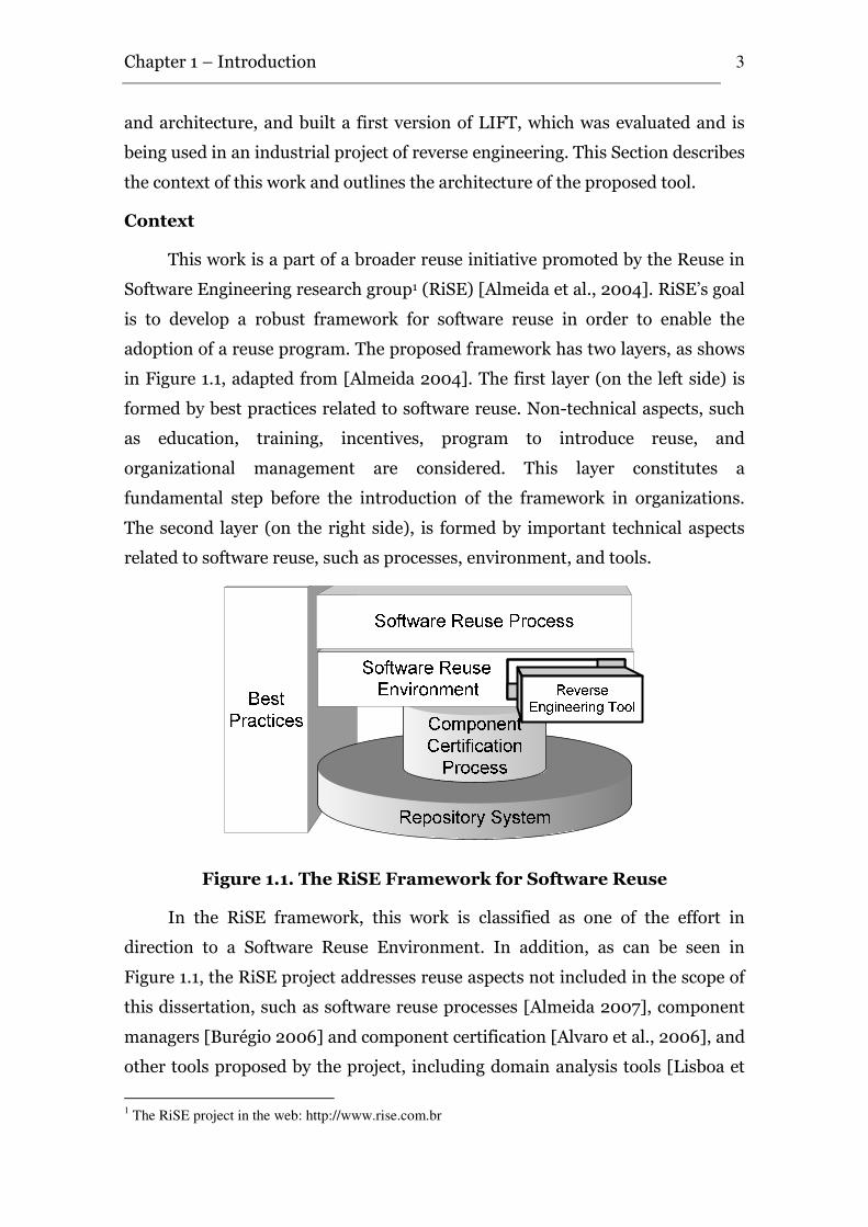
adoption of a reuse program. The proposed framework has two layers, as shows
in Figure 1.1, adapted from [Almeida 2004]. The first layer (on the left side) is
formed by best practices related to software reuse. Non-technical aspects, such
as education, training, incentives, program to introduce reuse, and
organizational management are considered. This layer constitutes a
fundamental step before the introduction of the framework in organizations.
The second layer (on the right side), is formed by important technical aspects
related to software reuse, such as processes, environment, and tools.
Figure 1.1. The RiSE Framework for Software Reuse
In the RiSE framework, this work is classified as one of the effort in
direction to a Software Reuse Environment. In addition, as can be seen in
Figure 1.1, the RiSE project addresses reuse aspects not included in the scope of
this dissertation, such as software reuse processes [Almeida 2007], component
managers [Burégio 2006] and component certification [Alvaro et al., 2006], and
other tools proposed by the project, including domain analysis tools [Lisboa et
1 The RiSE project in the web: http://www.rise.com.br
Chapter 1 – Introduction
4
al., 2007] and component search engines [Garcia et al., 2006, Mascena 2006,
Vanderlei et al., 2007] .
These efforts are coordinated and will be integrated in a full-fledged
enterprise scale reuse solution. The role of the LIFT tool on the RiSE project is
to provide a tool for legacy knowledge reuse, which is included in the software
reuse environment.
Moreover, this work was conduced in a partnership with industry,
represented by the Recife Center for Advanced Studies and Systems2
(C.E.S.A.R) and Pitang Software Factory3. C.E.S.A.R provided all infra-structure
and financial support to the development of this work, from surveys to
implementation, and Pitang contributed with the environment and real projects
to the case study. In addition, its staff and organizational experiences helped in
several discussions and definitions.
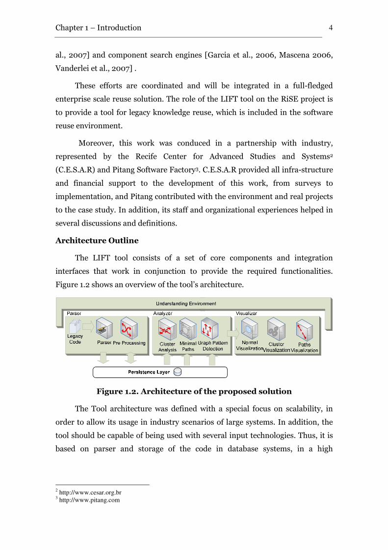
Architecture Outline
The LIFT tool consists of a set of core components and integration
interfaces that work in conjunction to provide the required functionalities.
Figure 1.2 shows an overview of the tool’s architecture.
Figure 1.2. Architecture of the proposed solution
The Tool architecture was defined with a special focus on scalability, in
order to allow its usage in industry scenarios of large systems. In addition, the
tool should be capable of being used with several input technologies. Thus, it is
based on parser and storage of the code in database systems, in a high
2 http://www.cesar.org.br
3 http://www.pitang.com
Chapter 1 – Introduction
5
abstraction level. Moreover, the tool has four main components: parser,
analyzer, visualizer and understanding environment.
In general lines, the parser component is responsible to perform the
parsing and to insert its code in database. The analyzer is responsible to analyze
the database and generate useful information for the user. The visualizer shows
the user this information, and provides software exploration and visualization
capabilities. Finally, the understanding environment integrates the other
components, providing the user interface for the user.
1.4. Out of Scope
As the proposed tool is part of a broader context, a set of related aspects
will be left out of its scope. In addition, recognized requirements are not a full
and closed set of functionalities that can be addressed by a reverse engineering
tool, which depends on the context where it is applied. However, we believe that
the identified requirements are the basis for the design of an effective reverse
engineering tool.
Thus, the following issues are not directly addressed by this work:
Process. Software process is a set of activities that leads to the
production of a software production [Sommerville 2000], and both academy
and industry agree that processes are fundamental to software engineering.
However, the tool presented in this work was designed to be used in the support
of reengineering or reverse engineering processes, like the one in the case study,
but the definition and evaluation of the process is not addressed in this work.
Forward Engineering. By definition, reengineering is composed by a
reverse engineering phase followed by a delta, which is the reorganization or
any alteration, and forward engineering [Chikofsky and Cross 1990,
Sommerville 2000, Pressman 2001]. Nevertheless, the focus of this work is
reverse engineering and system understanding; thus, forward engineering
issues are not addressed.
Estimation. Software estimation is an important issue in the economics
of software projects, in order to allow the planning, resources allocation and
good execution of software projects. It can be seen as a sub-area of software
engineering [Sommerville 2000]. Thus, due to its coverage, with several
Chapter 1 – Introduction
6
methods and approaches, in addition to non technical factors, reverse
engineering estimation is not addressed in this work.
Quality, Validation and Tests. The tool aids in reverse engineering
and system understanding tasks. However, since there is no agreed-upon
definition or test of understanding [Clayton et al., 1998], the creation of
validation and tests plans for system understanding can be seen as a new area or
discipline of reengineering, which is not addressed in this work.
1.5. Statement of the Contributions
As a result of the work presented in this work, the following contributions
may be enumerated:
• The extension of a study on the key developments in the field of
software reengineering, in an attempt to analyze this research area
and identify the next trends to follow.
• A survey based on the state-of-the-art and practice of reverse
engineering tools in order to understand and identify the weak and
strong points of the existing tools.
• The definition of requirements, architecture and implementation of
an effective reverse engineering tool, with the use and integration of
new methods, such as cluster and pattern detection, minimal paths
calculation and views usage.
• The definition, planning, operation, analysis, interpretation and
packaging of a case study which describes the use of the proposed
tool in an industrial project.
Besides the final contributions listed above, some intermediate results of
this work have been reported in the literature:
• Brito, K. S.; Garcia, V. C.; Lucrédio, D.; A.; Almeida, E. S.; Meira, S.
R. L. LIFT: Reusing Knowledge from Legacy Systems, In the
Brazilian Symposium on Software Components, Architectures and
Reuse (SBCARS), Campinas, São Paulo, Brazil, 2007.
• Brito, K. S.; Garcia, V. C.; Almeida, E. S.; Meira, S. R. L. A Tool for
Knowledge Extraction from Source Code, 21st Brazilian
Chapter 1 – Introduction
7
Symposium on Software Engineering, Tools Session, João Pessoa,
Paraíba, Brazil, 2007.
1.6. Organization of the Dissertation
The remainder of this dissertation is organized as follows.
Chapter 2 presents an extension of a survey about the origins of
reengineering concepts and ideas, processes and methods, and presents future
directions for research and developments in the area.
Chapter 3 surveys the state-of-the-art and practice on the reverse
engineering tools field, discussing their origins, fundamentals, strong and weak
points and main requirements, trying to establish some relations between them,
in order to define a base for the tool defined in this work.
Chapter 4 describes the LIFT tool: its requirements, architecture,
implementation and usage of the tool.
Chapter 5 presents the LIFT evaluation, with it context, definition,
planning, operation, analysis, interpretation and packing of the case study that
evaluated the viability of the tool.
Chapter 6 summarizes the contributions of this work, presents the related
work, and directions for future work.
Appendix A presents the questionnaire used in the experimental study.
Key Developments in the Field of Software Reengineering
“The history of software development began in the UK in 1948 [Ezran et
al., 2002]. In that year, the Manchester “Baby” was the first machine to
demonstrate the execution of stored-program instructions. Since that time,
there has been a continuous stream of innovations that have pushed forward
the frontiers of techniques to improve software development processes. From
subroutines in the 1960s through to modules in the 1970s, objects in 1980s, and
components in the 1990s [Clements and Northrop 2001], software
development has been a story of a continuously ascending spiral of increasing
capability and economy battled by increasing complexity. This necessity is a
consequence of software projects becoming more complex and uncontrollable,
along with problems involving schedules, costs, and failures to meet the
requirements defined by the customers, among others [Broy 2006]”. [Almeida
2007]
Even with these advances, since the old systems many times are built and
maintained in the last decades, they are mature, stable, with few bugs and
defects, having considerable information about the business. On the other hand,
the business dynamics demands constant changes in these systems, which
causes quality loss and difficult maintenance [Lehman and Belady 1985],
making software maintenance to be the most expensive software activity,
responsible for more than 90% of software budgets [Lientz et al., 1978, Standish
1984, Erlikh 2000]. Thus, this kind of software is called legacy software or
legacy systems, which can be defined as follow:
2
Chapter 2 – Key Developments in the Field of Software Reengineering
9
“Legacy software is critical software that cannot be modified efficiently.
In other words, it is software perceived by the business to be critical to its
operations, and yet difficult to modify without incurring great expense (in
terms of time, skill, etc). Legacy software is often described as being any or all
of the following: large, old, heavily modified, difficult to maintain, old-
fashioned.”[Brooke and Ramage 2001]
Thus, due to the difficulty in maintaining legacy systems, companies have
some alternatives: (i) to replace the applications by other software packages,
losing the entire knowledge associated with the application and needing
changes in the business processes to adapt to new applications; (ii) to rebuild
the applications from scratch, often still losing the knowledge embedded in the
application; or (iii) to perform application reengineering, reusing the
knowledge embedded in the systems.
In this context, reengineering legacy systems is a choice that prioritizes
knowledge reuse, instead of building everything from scratch again. Therefore,
reusing the embedded knowledge offers the opportunity to keep the same
quality of original systems, as well as decrease the maintenance costs.
Nevertheless, the organization scenario, costs and risks to perform the
reengineering must be addressed, in order to obtain its benefits [Brooke and
Ramage 2001].
In this way, this chapter surveys the origins of reengineering concepts and
ideas, processes and methods, and future directions for research and
developments in the area.
2.1. The Taxonomy
In 1990, Chikofsky & Cross [Chikofsky and Cross 1990] realized that
various terms for technologies to analyze and understand software systems had
been frequently misused or applied in conflicting ways, and defined and related
six terms already used in the practice, that became the default taxonomy for
reengineering. The terms and definitions are:
• Reverse Engineering is the process of analyzing a subject system
to identify the system’s components and their interrelationships,
and to create a representation of the system in another form or at a
Chapter 2 – Key Developments in the Field of Software Reengineering
10
higher level of abstraction. There are many subareas of reverse
engineering. Two subareas that are widely referred to it are
redocumentation and design recovery.
• Redocumentation is the creation or revision of a semantically
equivalent representation within the same relative abstraction level.
The resulting forms of representation are usually considered
alternative views (for example, dataflow, data structure, and control
flow) intended for a human audience.
• Design Recovery is a subset of reverse engineering in which
domain knowledge, external information, and deduction or fuzzy
reasoning are added to the observations of the subject system to
identify meaningful higher level abstractions beyond those
obtained directly by examining the system itself.
• Restructuring is the transformation from one representation
form to another at the same relative abstraction level, while
preserving the subject system's external behavior (functionality and
semantics).
• Forward Engineering is the traditional process of moving from
high-level abstractions and logical, implementation-independent
designs to the physical implementation of a system. Forward
engineering follows a sequence of going from requirements to
designing its implementation.
• Reengineering is the examination and alteration of a subject
system to reconstitute it in a new form and the subsequent
implementation of the new form.
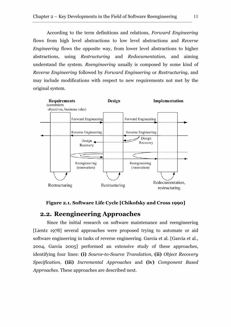
The relations among these terms are shown in Figure 2.1 [Chikofsky and
Cross 1990]. The key terms were defined based on three development life-cycle
stages, with clearly abstraction levels: Requirements, which is the specification
of the problem being solved, including objectives, constraints, and business
rules; Design, which is the specification of the solution; and Implementation,
which is the tasks of coding, testing, and delivery of the system.
Chapter 2 – Key Developments in the Field of Software Reengineering
11
According to the term definitions and relations, Forward Engineering
flows from high level abstractions to low level abstractions and Reverse
Engineering flows the opposite way, from lower level abstractions to higher
abstractions, using Restructuring and Redocumentation, and aiming
understand the system. Reengineering usually is composed by some kind of
Reverse Engineering followed by Forward Engineering or Restructuring, and
may include modifications with respect to new requirements not met by the
original system.
Figure 2.1. Software Life Cycle [Chikofsky and Cross 1990]
2.2. Reengineering Approaches
Since the initial research on software maintenance and reengineering
[Lientz 1978] several approaches were proposed trying to automate or aid
software engineering in tasks of reverse engineering. Garcia et al. [Garcia et al.,
2004, Garcia 2005] performed an extensive study of these approaches,
identifying four lines: (i) Source-to-Source Translation, (ii) Object Recovery
Specification, (iii) Incremental Approaches and (iv) Component Based
Approaches. These approaches are described next.
Chapter 2 – Key Developments in the Field of Software Reengineering
12
2.2.1. Source-to-Source Translation
Essentially, all program translators (both source-to-source translators
and compilers) operate via transliteration and refinement. The source program
is first transliterated into the target language on a statement-by-statement basis.
Various refinements are then applied in order to improve the quality of the
output. Although acceptable in many situations, this approach is fundamentally
limited to reengineering due to the low quality of the produced output.
Specially, it tends to be insufficiently sensitive to global features of the source
program and too sensitive to irrelevant local details.
The Lisp-to-Fortran translator proposed by Boyle [Boyle and
Muralidharan 1984] is based on the transformational approach. The translator
handles an applicative subset of Lisp which does not include hard-to-translate
features, such as the ability to create and execute new Lisp code. Readability is
not a goal of the translation. Rather, readability of the output is abandoned in
favor of producing reasonably efficient Fortran code. As discussed in the work
[Boyle and Muralidharan 1984], this translator is perhaps best thought of as a
Lisp to Fortran compiler rather than a source-to-source translator. The
transformation process is controlled by dividing it into a number of phases.
Each phase applies a transformation selected from a small set. The
transformations within each set are chosen in a way that conflicts among
transformations will not arise.
Waters [Waters 1988] presents an alternative translation paradigm -
abstraction and reimplementation. In this paradigm, the source program is first
analyzed in order to obtain a programming-language-independent
understanding of the computation performed by the program as a whole. Next,
the program is re-implemented in the target language based on this
understanding. In contrast to the standard translation approach of
transliteration and refinement, translation via analysis and reimplementation
utilizes an in-depth understanding, which makes it possible for the translator to
create target code without being constrained by irrelevant details of the source
program.
The main advantage of source-to-source translation is that it is faster
than traditional approaches, and it requires less expensive manual effort.
Chapter 2 – Key Developments in the Field of Software Reengineering
13
However, it is clear that there are still some significant limitations in the quality
of the output that is produced by typical translators. This can be clearly seen in
source-to-source translation, where human intervention is typically required in
order to produce acceptable output.
2.2.2. Object recovery and specification
The new technology of the late 1980's and early 1990's was the object-
oriented. The Object-Oriented paradigm (OO) offers some desirable
characteristics, which in some sense significantly helps improving software
reuse. This was the predominant software trend of the 1990's. According to the
literature, it should enhance maintainability, reduce the error rate and increase
productivity, with several advances to data processing [Meyer 1997].
The idea of applying object-oriented reverse engineering is that in a
simple way and with limited efforts the software engineer can make a model of
an existing system. With a model, one can reason about where a change can be
performed, its extent, and how it shall be mapped on the existing system.
Moreover, the new model is object-oriented and can serve as a basis for a future
development plan.
The first relevant work involving the object-oriented technology was
presented by Jacobson & Lindstrom [Jacobson and Lindstrom 1991], who
applied reengineering in legacy systems that were implemented in procedural
languages, such as C or COBOL, obtaining object-oriented systems. Jacobson &
Lindstrom state that reengineering should be accomplished in a gradual way,
because it would be impracticable to substitute an old system for a completely
new one (what would demand many resources). They considered three different
scenarios: changing the implementation without changing functionality; partial
changes in the implementation without changing functionality; and changes in
the functionality. Object-orientation was used to accomplish this
modularization. Jacobson & Lindstrom used a specific Computer-Aided
software Engineering (CASE) tool and defended the idea that reengineering
processes should focus also on tools to aid the software engineer.
Gall & Klösh [Gall and Klösch 1994] proposed heuristics to find objects
based on data store entities (DSEs) and non-data store entities (NDSEs) which
Chapter 2 – Key Developments in the Field of Software Reengineering
14
act primarily over tables representing basic data dependence information. The
tables are called (m, u) tables, since they store information on the manipulation
(m) and the use (u) of variables. With the help of an expert, a basic assistant
model of the object oriented application architecture is devised, for the
production of the final generated Reverse Object-Oriented Application Model
(ROOAM).
Yeh et al. [Yeh et al., 1995] proposed a more conservative approach based
not just on the search of objects, but directed to find abstract data types (ADTs).
Their approach, called OBAD, is encapsulated by a tool, which uses a data
dependence graph between procedure and structure types as a starting point for
the selection of abstract data types candidates. The procedures and structure
types are the graph nodes, and the references between the procedures and the
internal fields are the edges. The set of connected components in this graph
forms the set of candidate ADTs.
In 1995, Wilkening et al. [Wilkening et al., 1995] presented a process for
legacy systems reengineering using parts of their implementation and design.
The process begins with the preliminary source code restructuring, to introduce
some improvements, such as removal of non-structured constructions, “dead'”
code and implicit types. The purpose of this preliminary restructuring is to
produce a program that is easier to analyze, understand and restructure. Then,
the produced source code is analyzed and its representations are built in high-
level abstraction. Those representations are used in the subsequent
restructuring steps, redesign and redocumentation, which are repeated as many
times as necessary in order to obtain a fully restructured system. Next,
reimplementation and tests are performed, finalizing the reengineering process.
To transform programs from a procedural to an object-oriented
structure, Wilkening presupposes that the programs are structured and
modular, otherwise they cannot be transformed. Structured means that there
are no GOTO like branches from one segment of code to another, for instance.
Modular means that the programs are segmented in a hierarchy of code
segments, each one with a single entry and a single exit. The segments or
procedures should correspond to the elementary operations of the program.
Each operation should be reachable by invoking it from a higher level routine.
Chapter 2 – Key Developments in the Field of Software Reengineering
15
The other prerequisite is to establish a procedural calling tree for the subroutine
hierarchy so that all subroutines are included as part of the procedure with calls
or performs them.
Wilkening et al. also define three major prerequisites for object-oriented
reverse engineering: procedural structuring, modularization and inclusion of
subroutines.
Another fundamental work of object-oriented reengineering is presented
in [Sneed 1996], where Sneed describes a reengineering process aided by a tool
to extract objects starting from existent programs in COBOL. He emphasizes the
predominance of the object technology, mainly in distributed applications with
graphic interfaces, questioning the need to migrate legacy systems toward that
technology. He identifies obstacles to the object-oriented reengineering, such as
the object identification, the procedural nature of most of the legacy systems,
the code redundancy and the arbitrary use of names.
Similarly to Wilkening et al., Sneed assumes as prerequisites for the
object-oriented reengineering the structuring and programs modularization.
However, he also defends the existence of a system calls tree, to identify
procedure calls within the system. Sneed's object-oriented reengineering
process is composed of five steps: object selection, operation extraction, feature
inheritance, redundancy elimination and syntax conversion. The first step must
be performed by the user, optionally supported by a tool. The second step
extracts all the operations performed upon the selected objects, replacing the
removed code segments with calls to their respective objects. The third step
creates attributes in the objects, to represent the data that were accessed by the
operations removed in step two. The fourth step merges similar classes and
removes redundant classes. The final step converts the remaining classes into
Object-COBOL, in a straight forward conversion process.
The transformation of procedural programs into object-oriented
programs is not trivial. It is a complex multi-step, a m:n transformation process
relationship which requires human intervention in defining what objects should
be chosen. Although there are already some commercially available tools to aid
the tasks of reverse engineering, a bigger effort is still needed to face the
Chapter 2 – Key Developments in the Field of Software Reengineering
16
complexity of the existing systems, not only because of their size, but also due to
their intrinsic complexity.
2.2.3. Incremental approaches
The approaches presented in Sections 2.2.1 and 2.2.2 involves the entire system
reconstruction. For this reason, the software must be frozen until execution of
the process has been completed; in other words, no changes are possible during
this period. In fact, if a change or enhancement is introduced, the legacy system
and the renewal candidate would be incompatible, and the software engineers
would have to start the process all over again from the beginning. This situation
causes a loop between the maintenance and the reengineering process.
To overcome this problem, several authors have suggested wrapping the
legacy system, and considering it as a black-box component to be reengineered.
Due to the iterative nature of this reengineering process, during its execution
the system will include both reengineered and legacy components, coexisting
and cooperating in order to ensure the continuity of the system. Finally, any
maintenance activities, if required, have to be carried out on both the
reengineered and the legacy components, depending on the procedures they
have an impact on.
The first important iterative process was proposed by Olsem [Olsem
1998]. According to him, legacy systems are formed by four classes of
components (Software/Application, Data Files, Platforms and Interfaces) that
cannot be dealt with the same way. The incremental reengineering process
proposed by him uses different strategies for each class of components, reducing
the failure probabilities in the process.
Another important contribution from Olsem's work is that he proposes
two ways to perform incremental reengineering: with re-integration, in which
the reconstructed modules are re-integrated into the legacy system, and without
re-integration, in which the modules are identified, isolated and reconstructed,
maintaining the interface with the modules that were not submitted to the
process through a mechanism called “Gateway'”.
In 2003, Bianchi et al. [Bianchi et al., 2003] presented an iterative model
for reengineering legacy systems. The novelties of the proposed process include:
Chapter 2 – Key Developments in the Field of Software Reengineering
17
(i) the reengineering is gradual, i.e., it is iteratively executed on different
components (data and functions) in different phases; and (ii) during execution
of the process there will be coexistence of legacy components, which are:
components currently undergoing reengineering, reengineered components,
and new components added to the system to satisfy new functional requests.
In another work, Zou & Kontogiannis [Zou and Kontogiannis 2003]
proposed an incremental source code transformation framework that allows for
procedural system to be migrated to modern object oriented platforms. Initially,
the system is parsed and a high level model of the source code is extracted. The
framework introduces the concept of a unified domain model for a variety of
procedural languages such as C, Pascal, COBOL, and Fortran. Next, to keep the
complexity and the risk of the migration process into manageable levels, a
clustering technique allows the decomposition of large systems into smaller
manageable units. A set of source code transformations allows the identification
of an object model from each unit. Finally, an incremental merging process
allows the binding of the different partial object models into an aggregate
composite model for the whole system.
There are several benefits associated with iterative processes: by using
“divide et impera” (“divide-conquer”) techniques, the problem is divided into
smaller units, which are easier to manage; the outcomes and investment return
are immediate and concrete; the risks associated with the process are reduced;
errors are easier to find and correct, not putting the whole system at risk; and it
guarantees that the system will continue to work even during execution of the
process, preserving maintainers' and users' familiarity with the system [Bianchi
et al., 2000].
2.2.4. Component-Based approaches
Currently, on the top of object-oriented techniques, an additional layer of
software development, based on components is being established. The goals of
“componentware” are very similar to those of object-orientation: reuse of
software is to be facilitated and thereby increased; software shall become more
reliable and less expensive [Lee et al., 2003].
Chapter 2 – Key Developments in the Field of Software Reengineering
18
Component-Based Development (CBD) is not a new idea. McIlroy
[McIlroy 1968] proposed using modular software units in 1968, and reuse has
been behind many software developments. The extraction of reusable software
components from entire system is an attractive idea, since software objects and
their relationships incorporate a large amount of experience from past
development. It is necessary to reuse this experience in the production of new
software. The experience makes its possible to reuse software objects [Caldiera
and Basili 1991].
Among the first research work in this direction, Caldiera & Basili
[Caldiera and Basili 1991] explored the automated extraction of reusable
software components from existing systems. They propose a process that is
divided in two phases. First it chooses, from the existing system, some
candidates and packages them for possible independent use. Next, an engineer
with knowledge of the application domain analyzes each component to
determine the services it can provide. The approach is based on software models
and metrics. According to Caldiera & Basili, the first phase can be fully
automated: “reducing the amount of expensive human analysis needed in the
second phase by limiting analysis to components that really look worth
considering”.
Some years later, Neighbors [Neighbors 1996] presented an informal
research, performed over a period of 12 years, from 1980 to 1992, with
interviews and the examination of legacy systems, in an attempt to provide an
approach for the extraction of reusable components. Although the paper does
not present conclusive ideas, it gives several important warnings regarding large
systems. According to Neighbors, the architecture of large systems is a trade-off
between top-down functional decomposition and bottom-up support of layers of
Application Programming Interfaces (API’s or virtual machines). Therefore,
attempts to partition a system according to one of these approaches will not
succeed. A better partitioning is the idea of subsystems, which encapsulate
convenient to system designers, maintainers and managers. The next step is to
extract them into reusable components, which may be performed manually or
automatically.
Chapter 2 – Key Developments in the Field of Software Reengineering
19
Another work involving software components and reengineering may be
seen in [Alvaro et al., 2003], where they present a CASE environment for the
software reengineering based on components, called Orion-RE. The
environment uses software reengineering and Component-Based techniques to
rebuild legacy systems, reusing the available documentation and the built-in
knowledge in their source code. A software process model drives the
environment usage through the reverse engineering, to recover the system
design, and forward engineering, where the system is rebuilt using modern
technologies, such as design patterns, frameworks, component-based
development principles and middleware. Alvaro observed some benefits in the
reconstructed systems, such as greater reuse degree and easier maintenance, in
addition to benefits due to the automation achieved through CASE.
Other similar approach is proposed in [Lee 2003], where is presented a
process to reengineer an object-oriented legacy system into a component-based
system. The components are created based upon the original class relationships
that are determined by examining the program source code. The process is
composed of two parts: (i) to create basic components with composition and
inheritance relationship among constituent classes; and (ii) to refine the
intermediate component-based system using the metrics they propose, which
include connectivity strength, cohesion, and complexity. Finally, their approach
is based on a formal system model, reducing the possibility of misunderstanding
a system and enabling operations to be correctly executed.
These four approaches are examples of the tendency on reverse
engineering research, as observed by Keller et al. [Keller et al., 1999].
Component-Based approaches are being considered in reverse engineering,
mainly due to their benefits in reuse and maintainability. However, there is still
a lack of a complete methodology to reengineer legacy systems into component-
based systems. But this lack is not restricted to reverse engineering. As can be
seen in [Bass et al., 2000], the problems faced when considering Component-
Based approaches in reengineering are only a smaller set of the problems
related to Component-Based Software Engineering in general. While these
problems remain unsolved, reengineering may never achieve the benefits
related to software components.
Chapter 2 – Key Developments in the Field of Software Reengineering
20
2.3. New Research Trends
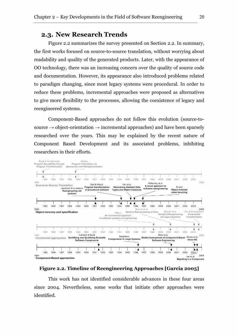
Figure 2.2 summarizes the survey presented on Section 2.2. In summary,
the first works focused on source-to-source translation, without worrying about
readability and quality of the generated products. Later, with the appearance of
OO technology, there was an increasing concern over the quality of source code
and documentation. However, its appearance also introduced problems related
to paradigm changing, since most legacy systems were procedural. In order to
reduce these problems, incremental approaches were proposed as alternatives
to give more flexibility to the processes, allowing the coexistence of legacy and
reengineered systems.
Component-Based approaches do not follow this evolution (source-to-
source → object-orientation → incremental approaches) and have been sparsely
researched over the years. This may be explained by the recent nature of
Component Based Development and its associated problems, inhibiting
researchers in their efforts.
Figure 2.2. Timeline of Reengineering Approaches [Garcia 2005]
This work has not identified considerable advances in these four areas
since 2004. Nevertheless, some works that initiate other approaches were
identified.
Chapter 2 – Key Developments in the Field of Software Reengineering
21
The emergence of Aspect-Oriented Software Development (AOSD)
technologies started a new trend. Investigations about AOSD in the literature
have involved to determine the extent to which it can be used to improve
software development and maintenance, along the lines discussed by Bayer
[Bayer 2000]. Lippert & Lopes [Lippert and Lopes 2000], present a study that
points the ability of the AOSD in facilitating the separation of the exceptions
detection and handling concern, involving the examining and reengineering of a
Java-built framework [Kiczales et al., 2001].
An approach to retrieve the knowledge embedded in an object-oriented
legacy system using AOSD is also presented in [Garcia 2005]. The Phoenix
approach aids the migration from object-oriented code, written in Java, to a
combination of objects and aspects, using AspectJ. It uses aspect mining in
order to identify possible crosscutting concerns from the OO source code and
extracts them through refactoring into new aspect-oriented code. Some benefits
of this approach are: (i) requirements traceability, (ii) better legibility; (iii)
better maintainability; (iv) automatization and (v) aspects reuse. In addition,
this approach has some problems, such as (i) a high effort to previously build
the transformers, (ii) problems with the Aspect notation and (iii) a lack of a test
method to verify the new system.
Additionally, many methods and tools have been proposed to port legacy
applications toward a top-down or a bottom-up way. The bottom-up approaches
consist in focus on the reengineer process in the data access of systems.
Otherwise, the top-down way consists in focusing on the user interface
interactions.
The bottom-up approaches consists in focus on understanding of
database layer of legacy applications. According to Sneed & Erdos [Sneed and
Erdos 1996], data is the essence of business information systems and business
transactions are directed toward creating, maintaining and utilizing the
company data stores. They propose a method for identifying and extracting
business rules by means of data output identification and program stripping. In
addition, Bianchi [Bianchi 2000] proposed an iterative method and process for
data reengineering, and Yeh & Li [Yeh and Li 2005] a process for extracting
entity relationship diagram from a table-based legacy database.
Chapter 2 – Key Developments in the Field of Software Reengineering
22
The top-down approaches are based on the analysis of system interfaces
and system behavior and focus on port legacy applications toward new
environments through the migration of their user interfaces (UI). In 1999, Liu
& Alderson [Liu et al., 1999] proposed a semiotic approach to requirements
recovery by studying the legacy system’s behavior, which includes input, output
and other user interactions. In addition, this approach was used to migrate
legacy graphical user interfaces (GUIs) from one toolkit to a new one [Moore
and Moshkina 2000], to migrate legacy systems using character based UIs
directly onto GUIs [Aversano et al., 2001] and onto an abstract description for a
successive implementation on GUIs, World Wide Web (WWW) or Wireless
Application Protocol (WAP) UIs [Kapoor and Stroulia 2001].
In addition to these approaches, with the advances of data mining
techniques a new trend starts to appear. El-Ramly & Stroulia [El-Ramly et al.,
2002a, El-Ramly et al., 2002b] present a process for software requirements
recovery that adopt data mining to discover patterns by the legacy application
users, based on traces of their interaction with the application. Another
approach using data mining techniques was proposed by Sartipi et al. [Sartipi et
al., 2000]. This method aims to recover the high level design of legacy systems
by mining the system in a database. He defined the Architectural Query
Language (AQL) language, which is used by the user to define the queries to be
applied in the database to recover the application design.
2.4. Key points of Software Reengineering
Even with the existence of many processes, methods and approaches to
reengineering, some flaws still exist. Currently, unresolved issues include (i)
the recovery of the entire system (interface, design and database), and to trace
the requirements from interface to database access, instead of only
architectural, database or user interface recovery; (ii) the recovery of system
functionality, i.e., what the system does, instead of recovering only the
architecture, that shows how the system works; (iii) the difficult of managing
the huge data amount present in the systems; and (iv) the high dependency of
the expert’s knowledge.
In addition, Müller et al. [Müller et al., 2000] identified that “in current
research and practice, the focus of both forward and reverse engineering is at
Chapter 2 – Key Developments in the Field of Software Reengineering
23
the code level. Forward engineering processes are geared toward producing
quality code. The importance of the code level is underscored in legacy systems
where important business rules are actually buried in the code. During the
evolution of software, change is applied to the source code, to add function, fix
defects, and enhance quality. In systems with poor documentation, the code is
the only reliable source of information about the system. As a result, the
process of reverse engineering has focused on understanding the code.”
However, the code does not contain all the information needed. Typically,
knowledge about architecture and design tradeoffs, engineering constraints, and
the application domain only exists in the minds of the software engineers [Bass
et al., 1997]. Nevertheless, over time memories fade, people leave, documents
decay and complexity increases [Lehman 1980], turning the source code the
only source of legacy systems knowledge, and making the reverse engineering a
hard and expensive activity.
In studies trying to establish a roadmap for reverse engineering research
for the new millennium [Müller 2000, Canfora and Penta 2007], researchers
identified, among other things, that tool integration and adoption should be
central issues for the next decade. Also, we need to evaluate reverse
engineering tools and technology in industrial settings with concrete
reengineering tasks at hand, to increase tool maturity and interoperability, and
this adoption.
2.5. Chapter Summary
Reengineering is the examination and alteration of a subject system to
reconstitute it in a new form and the subsequent implementation of the new
form. It is composed by a Reverse Engineering phase, which is the system
understanding, followed by Forward Engineering phase, which is the re-
implementation [Chikofsky and Cross 1990]. This process can be a way for
companies to decrease maintenance costs of legacy systems, in addition to reuse
legacy embedded knowledge in new systems projected to attend new demands
of its business dynamics.
In this chapter, the taxonomy of reengineering was presented, as well as a
survey on reengineering approaches. Also, the flaws on current approaches, the
Chapter 2 – Key Developments in the Field of Software Reengineering
24
new research trends and the future perspectives were presented, pointing to the
needs for tools to support the reverse engineering tasks.
In this context, the next chapter presents the state-of-the-art and practice
on the reverse engineering tools field, discussing their origins, fundamentals
and main requirements, strong and weak points, in order to define a base for the
tool defined in this work.
Reverse Engineering Tools: The State-of-the-Art and Practice
Reverse engineering is the process of analyzing a subject system to identify
the system’s components and their interrelationships; and create a
representation of the system in another form or at a higher level of abstraction
[Chikofsky and Cross 1990].
Despite the maturity of reengineering and reverse engineering research,
and the fact that many pieces of reverse engineering work seem to timely solve
crucial problems and to answer relevant industry needs, studies indicate that
the adoption of current available tools to automate the tasks in industry is still
limited [Müller 2000, Canfora and Penta 2007].
In this regard, this chapter surveys the state-of-the-art and practice on the
reverse engineering tools field, discussing their origins, fundamentals, strong
and weak points and main requirements, trying to establish some relations
between them, in order to define a base for an efficient tool to support reverse
engineering activities in industrial environments.
The survey was based on the main literature of reengineering, reverse
engineering and software engineering areas, including the Working Conference
on Reverse Engineering (WCRE), the International Conference on Software
Maintenance (ICSM), the European Conference on Software Maintenance and
Reengineering (CSMR), the International Conference on Program
Comprehension (ICPC), the International Conference on Software Engineering
(ICSE), the IEEE Transactions on Software Engineering, and the Journal of
Systems and Software, among others. In addition, web search engines, such as
3
Chapter 3 – Reverse Engineering Tools
26
www.scirus.com and www.google.com, and the web portal of ACM and IEEE
organizations were also consulted, aiming to find more data related to the area.
3.1. Reverse Engineering Tools
The reverse engineering and program comprehension were always
present in the software engineering context. Initially, these activities were
performed by reading the source code, in most cases in the write and compile
environment itself. In the 80s, two kinds of work were created to assist the tasks
of source code understanding: (i) grep4-like tools, such as grep, egrep, and
fgrep, which match regular expressions, and (ii) tools that detect plagiarism in
programs [Grier 1981, Berghel and Sallach 1984, Madhavji 1985].
In 1992, Paul [Paul 1992] analyzed these tools and recognized the main
criticism for these approaches. The general criticism of grep-like tools, mainly
for tasks involving finding program patterns, is that they are predominantly
line-based, match extremely low-level syntactic entities like characters, and
cannot be used effectively to express constraints that exist within patterns. On
the order hand, plagiarism detectors are mostly based on software metrics and
allow very little user interaction, neither of which is ideal for the kinds of
problems addressed. Based on these facts, Paul proposed the SCRUPLE, A
Reengineer’s Tool for Source Code Search, which focuses on source code search,
addressing the automatic detection of source code sections that fit patterns
defined in a pattern language. In this work, Paul claims that the efficiency of
automatic search lies in the representation of the source code and the pattern
being searched.
A prototype was built for C and PL/AS programming languages, and run
in the Centre for Advanced Studies of IBM Canada. In general, SCRUPLE was
demonstrated as an effective tool to find matches of source code fragments
based on partial specifications. Although many other issues are required to
support an effective reverse engineering tool, this tool can be considered the
first step towards it.
Along the years, prototypes of the tool were built and demonstrated at
conferences. Although the project was supported by a fellowship from IBM
4 http://www.gnu.org/software/grep/
Chapter 3 – Reverse Engineering Tools
27
Canada LTD., detailed information about practical use of the tool in other
industrial context was not found.
In 1988, Müller and Klashinsky [Müller and Klashinsky 1988] built the
Rigi, a model and a tool for programming-in-the large. They used a graph
model and abstraction mechanisms to structure and represent the information
accumulated during the development process. According to Müller and
Klashinsky, Rigi was designed to address three of the most difficult problems in
the area of programming large systems: (i) the mastery of the structural
complexity of the large software systems, (ii) the effective presentation of all
information accumulated during the development process, and (iii) the
definition of procedures for checking and maintaining the completeness,
consistency and traceability of system descriptions. The major objective of Rigi
was to effectively represent and manipulate the building blocks of software
systems and their numerous dependencies. The tool has four functional
requirements (FR): (FR1) Readability and ease of understanding of system
descriptions; (FR2) Defining system structure; (FR3) Interface consistency
and integration mechanisms; and (FR4) Version and release control;
The Rigi project was continually improved and in 1993 Müller [Müller et
al., 1993] presented a new perspective to it, that was to understand software
systems using reverse engineering technology perspectives from the project.
This work presented a reverse engineering technology developed as part of the
Rigi project, which involves the identification of software artifacts in the subject
system and the aggregation of these artifacts to form more abstract architectural
models. For the reverse engineering perspectives, they focused a new set of
functional and non-functional requirements (NFR) requirements, which are
(FR5) Involving the user; (FR6) Summarizing software structure, (FR7)
Documenting with views, and (NFR1) Scalability, flexibility, and extensibility.
The approach was used in projects at IBM Canada.
Nowadays, Rigi is an open source tool that supports reverse engineering
of programs written in C, C++, COBOL and PL/AS. In addition, according to the
tool’s website5, an extension to support JAVA applications is being developed as
part of a Master Dissertation. Furthermore, Rigi was used in several industrial
5 http://www.rigi.csc.uvic.ca
Chapter 3 – Reverse Engineering Tools
28
projects, such as the reverse engineer of a 57 kilo lines of code (KLOC) and a 82
KLOC physics programs, in 1990 and 1991, written in COBOL and C program
languages respectively, the analysis of a large commercial database manager
(SQL/DS) between 1992 and 1993, the examination of NASA's CLIPS expert
system shell, and the use by NOKIA to support visualization and abstraction,
with published papers in 2002 and 2003.
In 1997, Singer [Singer et al., 1997] performed an examination of the
software engineering work practices, and discusses the advantages of
considering work practices in designing tools for software engineers. Moreover,
it was presented three functional and seven non functional requirements for a
tool that support systems comprehension, using them to define the TkSee tool.
The functional requirements are: (FR1) Provide search capabilities such that
the user can search for, by exact name or by way of regular expression pattern-
matching, any named item or group of named items that are semantically
significant in the source code, (FR2) Provide capabilities to display all relevant
attributes of the items retrieved in requirement FR1, and all relationships
among them, and (FR3) Provide capabilities to keep track of separate searches
and problem-solving sessions, and allows the navigation of a persistent history.
On the other hand, the Non-Functional Requirements are: (NFR1) To be able
to automatically process a body of source code of very large size, i.e. consisting
of at least several million lines of code, (NFR2) Respond to most queries
without perceptible delay, (NFR3) Process source code in a variety of
programming languages, (NFR4) Wherever possible, be able to interoperate
with other software engineering tools, (NFR5) Permit the independent
development of user interfaces (clients), (NFR6) Be well integrated and
incorporate all frequently-used facilities and advantages of tools that SE’s
already commonly use, and (NFR7) Present the user with complete
information, in a manner that facilitates the “just in time comprehension”.
The project ran from 1995 to 2006 and supports Assembler, Pascal and
C/C++ programming languages. According to project website6, it is complete.
The project produced several publications in conferences and, according to
Singer, was used in a large telecommunications system of the company which
6 http://www.site.uottawa.ca/~tcl/kbre/
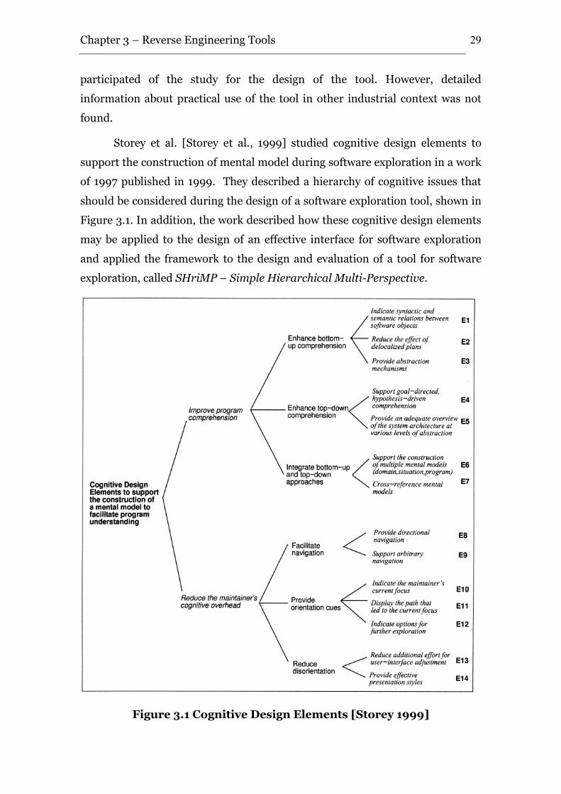
Chapter 3 – Reverse Engineering Tools
29
participated of the study for the design of the tool. However, detailed
information about practical use of the tool in other industrial context was not
found.
Storey et al. [Storey et al., 1999] studied cognitive design elements to
support the construction of mental model during software exploration in a work
of 1997 published in 1999. They described a hierarchy of cognitive issues that
should be considered during the design of a software exploration tool, shown in
Figure 3.1. In addition, the work described how these cognitive design elements
may be applied to the design of an effective interface for software exploration
and applied the framework to the design and evaluation of a tool for software
exploration, called SHriMP – Simple Hierarchical Multi-Perspective.
Figure 3.1 Cognitive Design Elements [Storey 1999]
Chapter 3 – Reverse Engineering Tools
30
The SHriMP tool was developed using the Rigi structure. Thus, it can be
used for the same programming languages: C/C++, Cobol, PL/As. In addition, it
has a plug-in to JAVA code and is able to understand complex knowledge bases,
in conjunction with the Protégé7 tool.
Although the list of several sponsors in the tool website8, such as IBM,
National Cancer Institute, U.S., and Defense Research and Development
Canada, detailed information about practical use of the tool in industrial context
was not found.
In 2000, Zayour and Lethbridge [Zayour and Lethbridge 2000]
introduced a methodology based on cognitive analysis that is aimed towards
maximizing the adoptability of a tool. They applied cognitive analysis to identify
cognitively difficult aspects of maintenance work, and then derived cognitive
requirements to address these difficulties. Thus, they described the approach in
the context of the implementation of a reverse engineering tool called DynaSee.
Zayour and Lethbridge based the study on the human short term
memory (STM) capabilities, which is related to the amount of attention and
mental energy that is required by an engineer to accomplish a task. Thus, they
sorted the requirements into two categories: Minimize the number of artifacts
that have to be kept in STM, and Minimize STM fading. The first requirements
comprises (FR1) Make the required artifacts easily available to the user, (FR2)
Facilitate meaningful encoding, and (FR3) Reduce the uncertainty during
exploration. The last requirements comprise (FR4) Minimize the time that
artifacts have to be retained in STM, and (FR5) Minimize the complexity of
tasks among successive artifact acquisitions. These requirements were used to
implement the DynaSee tool and to apply it in context of a telecommunication
company.
Despite of information about which programming languages are
supported by DynaSee tool, it was used in a telecommunications system largely
written in a proprietary language and contains several million lines of code with
over 16000 routines in over 8000 files. This system is the same one used by the
7 http://protege.stanford.edu/
8 http://www.thechiselgroup.org/shrimp
Chapter 3 – Reverse Engineering Tools
31
TKSee tool. Currently, DynaSee was incorporated by TkSee tool, and became a
part of them.
Favre [Favre 2001] claims that large software products are difficult to
understand because they are made of many entities of different types in
concrete representations, usually not designed with software comprehension in
mind. Thus, in 2001 he proposed the GSEE: a Generic Software Exploration
Environment made of an object-oriented framework and a set of customizable
tools that, with only few lines of implementation, produces graphical views from
virtually any source of data. In order to build this tool, three requirements were
kept in mind: (FR1) multi-source exploration, (FR2) multi-visualization
exploration and (FR3) customizable exploration.
According to Favre, the environment can be used to produce views from
virtually any source of data, and was successfully applied in the context of
Dassault Système, in a software composed of more than 40.000 C++ classes.
However, according to a personal contact with Favre9, “the tool is discontinued.
This was a running prototype but we were unable to find means to consolidate
it and make it really usable by third parties.”
In 2003, Lanza and Ducasse [Lanza and Ducasse 2003] presented the
concept of polymetric view, a lightweight software visualization technique
enriched with software metrics information. The work discussed benefits and
limits of several predefined polymetrics views that were implemented in the
CodeCrawler tool. In the same year, it was published a set of lessons learned in
building the tool [Lanza 2003], including the implementation, and was
identified five key issues pertinent to the implementation of a reverse
engineering tool, namely (i) the overall architecture, (ii) the internal
architecture, (iii) the visualization engine, (iv) the metamodel and (v) the
interactive facilities.
The CodeCrawler is an open source tool, under BSB license. It relies on
the FAMIX Metamodel [Demeyer et al., 2001] that has been implemented in the
Moose environment [Nierstrasz et al., 2005] which models object-oriented
languages such as C++, Java, Smalltalk, and also procedural languages like
9 http://megaplanet.org/jean-marie-favre/
Chapter 3 – Reverse Engineering Tools
32
COBOL. Several papers discuss the tool, and some case studies are shown. One
interesting case study is the understanding of a 1.2 million LOC of C++ code.
However, CodeCrawler author did not explain performance issues of this case
study, which is important because the tool keep all entities in memory. In
addition, according to the tool’s website, it was downloaded more than 2.000
times, but a public track about companies and projects that use the tool was not
found.
Four years after, Schäfer et al. [Schäfer et al., 2006] built the SEXTANT
Software Exploration Tool. In this work, it was discussed a set of functional
requirements for software exploration tools, and present the SEXTANT tool
based on these requirements, which are: (FR1) Integrated Comprehension,
(FR2) Cross-Artifact Support, (FR3) Explicit Representation, (FR4)
Extensibility, and (FR5) Traceability. In addition, Schäfer et el. discussed
SEXTANT tool with respect to the requirements of other three works that
discuss comprehension support with respect to cognition, also related in our
work [Singer 1997, Storey 1999, Zayour and Lethbridge 2000].
The SEXTANT tool only supports JAVA code, and is still a research
project with no industrial use identified by the author.
3.2. Towards an Effective Software Reverse Engineering Tool
Figure 3.2 summarizes the timeline of research on the software reverse
engineering tools, from the first efforts after the pure source code visualization
techniques [Paul 1992] and adaptation of an engineering tool to improve
reengineering capabilities [Müller 1993] until more recent efforts to source code
exploration [Schäfer 2006]. This timeline does not intend to be complete, but is
based on the most known tools, providing useful information about the
requirements of a reverse engineering tool. Some requirements are commonly
supported by several tools, and others are specific of others. In order to define a
set of requirements for an effective reverse engineering tool, we analyzed these
requirements and tried to establish a relationship among them.
From the analysis of the tools presented in Section 2.1, six functional and
three non functional requirements needed to the development of an effective
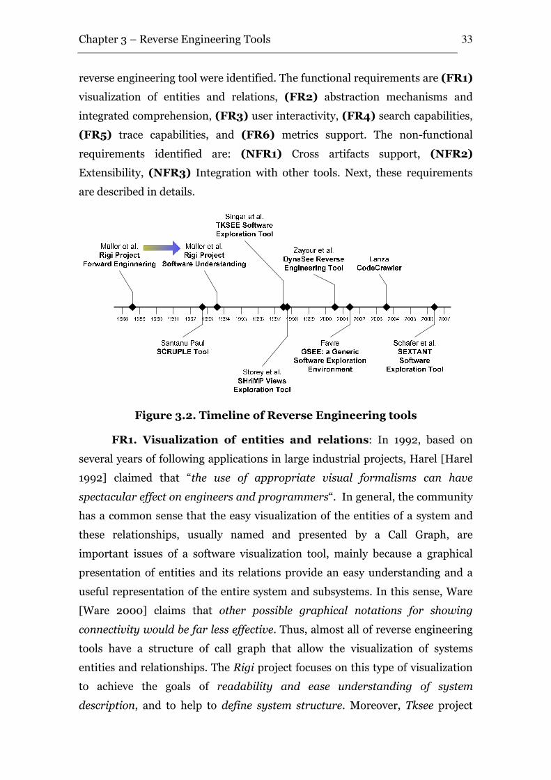
Chapter 3 – Reverse Engineering Tools
33
reverse engineering tool were identified. The functional requirements are (FR1)
visualization of entities and relations, (FR2) abstraction mechanisms and
integrated comprehension, (FR3) user interactivity, (FR4) search capabilities,
(FR5) trace capabilities, and (FR6) metrics support. The non-functional
requirements identified are: (NFR1) Cross artifacts support, (NFR2)
Extensibility, (NFR3) Integration with other tools. Next, these requirements
are described in details.
Figure 3.2. Timeline of Reverse Engineering tools
FR1. Visualization of entities and relations: In 1992, based on
several years of following applications in large industrial projects, Harel [Harel
1992] claimed that “the use of appropriate visual formalisms can have
spectacular effect on engineers and programmers“. In general, the community
has a common sense that the easy visualization of the entities of a system and
these relationships, usually named and presented by a Call Graph, are
important issues of a software visualization tool, mainly because a graphical
presentation of entities and its relations provide an easy understanding and a
useful representation of the entire system and subsystems. In this sense, Ware
[Ware 2000] claims that other possible graphical notations for showing
connectivity would be far less effective. Thus, almost all of reverse engineering
tools have a structure of call graph that allow the visualization of systems
entities and relationships. The Rigi project focuses on this type of visualization
to achieve the goals of readability and ease understanding of system
description, and to help to define system structure. Moreover, Tksee project
Chapter 3 – Reverse Engineering Tools
34
shows this kind of structure to display all relevant attributes of the items, and
all relationships among them. In addition, the PBS, SHriMP, GSEE, Code
Crawler and Sextant tools provide this type of functionality.
FR2. Abstraction mechanisms and integrated comprehension:
The understanding of large software system is a hard task. The visualization of
the entire system in one single view usually presents a lot of information that is
difficult to understand. Thus, the capability to present several views and
abstraction levels as well as to allow user create and manipulate these views is
fundamental for the understanding of large software systems. In this sense, the
Rigi and the SHriMP tools provide specific facilities to abstraction and
generation of new views of the system.
FR3. User interactivity: As mentioned previous, the capability of
creation of user abstractions and views of a system is a desirable requirement in
a software reverse engineering tool. In addition, other interactivity options are
also important, as the possibility of user annotations about the code,
abstractions and views. This type of functionality permits recognition of
information about the assets by other user or by the same user another time in
the future, avoiding duplicate work. Other important interactivity issue is the
possibility to show to the user an easy mechanism to switch between the high
level code visualization and the source code, to permit to him the view of the two
kind of code representation without lose cognition information. In this sense,
almost all of studied reverse engineering tools have this type of user
interactivity, with exception of TkSee and DynaSee tools.
FR4. Search capabilities: During software exploration, related
artifacts are successively accessed. Thus, it is highly recommended to minimize
the artifact acquisition time, as well as the number and complexity of
intermediate steps in the acquiring procedure. This way, the support of arbitrary
navigation, such as search capabilities, is a common requirement in software
reverse engineering tools, and has focus on all studied reverse engineering tools,
with exception of PBS, Code Crawler and Sextant.
FR5. Trace Capabilities: The software reverse engineering is a task
that requires a large cognitive effort to maintain the followed paths in memory.
In general, the user spends many days following the execution path of a
Chapter 3 – Reverse Engineering Tools
35
requirement to understand it, and often is difficult to mentally recover the
execution path and the already studied items. Thus, to keep the user from
getting lost in the execution paths, the tools should provide ways to backtrack
the flows of the user, show already visited items and paths, and indicate options
for further exploration. In this sense, the TkSee, SHriMP, DynaSee and Sextant
tools have special focus on provide trace capabilities to the user.
FR6. Metrics Support: Visual presentations can present a lot of
information in a single view. Reverse engineering tools should take advantage of
these presentations to show some useful information in an effective way. This
information can be metrics about cohesion and coupling of modules, length,
internal complexity or other kinds of information chosen by user, and can be
presented, for example, as the color, length and format of entities in a call
graph. In this sense, the Rigi tool provides some metrics in the visual
presentation, and the CodeCrawler introduced the concept of Polimetric Views,
that is a visual approach to enhance the visual presentation of a system. The
approach consists in the possibility of enrich the basic visualization method by
rendering up to five metric measurements on a single node simultaneously,
based on node size (width and height), node color and node position (X and Y
coordinates). They present examples of metrics that can be applied, which can
be (i) modules metrics: number of methods or functions extended, number of
attributes, number of invocation calls and number of LOC of a module; (ii)
method metrics: method lines of code, number of parameters, number of
invocations of other methods within method body, number of accesses on
attributes and number of statements in method body; and (iii) attribute
metrics: number of direct accesses from outside of its module, number of direct
accesses from within its module and number of times directly accessed. The
approach was useful mainly in the first steps of reverse engineering.
NFR1. Cross artifacts support: A software system is not only source
code, but a set of semantic (source code comments, manuals and documents)
and syntactic (functions, operations and algorithms) information spread in a lot
of files. The need for cross-artifact navigation has been identified in the context
of a field study during the corrective maintenance of a large-scale software
system [Mayrhauser and Vans 1997]. In this field study, requirements on tool
Chapter 3 – Reverse Engineering Tools
36
capabilities were derived based on developers’ information needs; the most
important ones concern navigation over arbitrary software artifacts. Thus, a
reverse engineering tool should be capable of dealing with several kinds of
artifacts, and Rigi, TkSee, PBS, GSEE and Sextant tools provide support to it.
NFR2. Extensibility: The software development area is in constant
evolution. The technologies and tools are in constant change, and their lifetime
is even shorter. Therefore, due the fact of diffusion of a wide number of
programming language dialects – a phenomenon known as the “500 language
problem” – [Lammel and Verhoef 2001], is desirable that a reverse engineering
tool is not able of being used with only a specific language, technology or
paradigm, but should be flexible, extensible, and not technology-dependent, in
order to permit its usage with a high range of systems and increasing its
lifetime. In this sense, the Rigi, TkSee, PBS and Sextant are capable to be
extensible to be used in reverse engineering activities of more than one
technology.
NFR3. Integration with other tools: Several tools were developed to
aid in reverse engineering tasks, as well to help the forward engineering. In
addition, tool developers cannot foresee all contexts in which it will be used.
Thus, as software reuse researchers advocate [Krueger 1992], it is not necessary
reinvent new solutions when others already exists, and a tool should permit that
features present in other tools could be incorporated in it, adopting standards to
permit communication between distinct tools. In this sense, the architecture of
TkSee, PBS, DynaSee and Sextant provides capabilities to integration with other
tools.
3.3. Summary of the Study
Table 3.1 shows the relation between the works described in Section 3.1 and the
requirements from Section 3.2. In the table, an “X” indicates that the
requirement is satisfied by the work. Gaps show that the requirement is not
even addressed by the work.
By analyzing Table 3.1, it can be seen that there are some gaps in reverse
engineering tools and important requirements are not considered by them,
which often implements only a subset of these requirements.
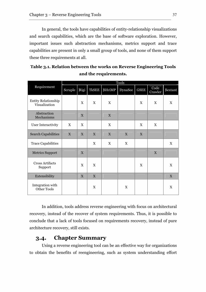
Chapter 3 – Reverse Engineering Tools
37
In general, the tools have capabilities of entity-relationship visualizations
and search capabilities, which are the base of software exploration. However,
important issues such abstraction mechanisms, metrics support and trace
capabilities are present in only a small group of tools, and none of them support
these three requirements at all.
Table 3.1. Relation between the works on Reverse Engineering Tools
and the requirements.
Tools Requirement
Scruple Rigi TkSEE SHriMP DynaSee GSEE Code
Crawler Sextant
Entity Relationship Visualization
X X X X X X
Abstraction Mechanisms
X X
User Interactivity X X X X X
Search Capabilities X X X X X X
Trace Capabilities X X X X
Metrics Support X X
Cross Artifacts Support
X X X X
Extensibility X X X
Integration with Other Tools
X X X
In addition, tools address reverse engineering with focus on architectural
recovery, instead of the recover of system requirements. Thus, it is possible to
conclude that a lack of tools focused on requirements recovery, instead of pure
architecture recovery, still exists.
3.4. Chapter Summary
Using a reverse engineering tool can be an effective way for organizations
to obtain the benefits of reengineering, such as system understanding effort
Chapter 3 – Reverse Engineering Tools
38
reduction. However, choosing and using a reverse engineering tool is not a
trivial task, despite of the quantity of existent tools.
In this chapter, eight reverse engineering tools were discussed. This
survey contribution is twofold: it can be seen as a guide to aid organizations in
the adoption of a reverse engineering tool, and it also offers the basis for a
definition of a new reverse engineering tool. Additionally, based on the
requirements of existing tools, a set of requirements for an effective reverse
engineering tool was presented. In this context, the next chapter presents the
tool proposed by this work.
LIFT: Legacy InFormation Retrieval Tool
Based on the survey that identified the main approaches for reengineering,
with its strong and weak points, presented in Chapter 2, as well as the study of
reverse engineering tools presented in Chapter 3, this work specifies, designs,
implements and performs a case study of a tool for reverse engineering, focused
on extract the requirements of legacy systems, in general performed by
engineers with low knowledge about the systems which many times have few or
none documentation.
This chapter presents the requirements, architecture, implementation and
usage of the tool.
4.1. Requirements
The previous chapter discussed the main requirements of eight reverse
engineering tools, and identified some gaps and important requirements that
are not considered by them, which in general implement only a subset of these
requirements. In addition, these requirements were presented to an experienced
team of the Pitang Software Factory, which had already performed reverse
engineer of almost 2 million lines of code in 2006. Furthermore, the experience
of the C.E.S.A.R Study Center, the RiSE Group and author experience were
considered in the definition of the requirements.
The requirements identified in the survey are: (FR1) visualization of
entities and relations, (FR2) abstraction mechanisms and integrated
comprehension, (FR3) user interactivity, (FR4) search capabilities, (FR5)
trace capabilities, and (FR6) metrics support. The non functional requirements
4
Chapter 4 – LIFT: Legacy Information Retrieval Tool
40
identified are: (NFR1) Cross artifacts support, (NFR2) Extensibility and
(NFR3) Integration with other tools.
In addition, based on the lack of reengineering approaches discussed in
Chapter 2, we defined two new functional requirements: (FR7) the recovery of
the entire system (interface, design and database), and (FR8) the trace of
requirements from interface to database access. Furthermore, in conjunction
with the industry involved in this study, we defined a new functional
requirement, which is (FR9) possibility of semi-automatic suggestions. Finally,
in agreement with the literature and with the industry group, the non functional
requirements of (NFR4) scalability and (NFR5) Maintainability and
Reusability were prioritized in the tool. Next, we discuss these new
requirements.
FR7. The recovery of the entire system: Many reverse engineering
tools concentrate on extracting the structure or architecture of a legacy system
with the goal of transferring this information into the minds of the software
engineers trying to understanding it [Müller 2000]. However, the software
structure is not the only useful information. Most software systems for business
and industry are information systems, and maintain and process vast amounts
of persistent business data. Thus, the understanding of the data that is stored by
the system is important. However, the research in data reverse engineering has
been under-represented in the software reverse engineering scenario, and these
two concepts (data and software reverse engineering) are separated. While the
main focus of code reverse engineering is on improving human understanding
about how this information is processed, data reverse engineering tackles the
question of what information is stored and how this information can be used in
a different context. [Müller 2000].
In addition, the user interface contains the information presented to user,
and required from him, and includes lots of information about the business
rules of the system.
In this sense, we believe that the possibility of recovery the entire system
including user interface, the general design, and at least the database structure
in a single tool should be addressed by an effective reverse engineering tool.
Chapter 4 – LIFT: Legacy Information Retrieval Tool
41
FR8. The trace of requirements from interface to database
access: In Chapter 3, we discussed the requirement of (F5) Trace capabilities,
which is related to reduce the cognitive effort of the user in reverse engineering
tasks. In addition, we believe that other form of trace is desirable. The new
requirement (F7) defines that is important the recovery of entire system, from
interface to databases. However, is not important only the recovery but ways of
isolate and show to the user the execution paths of application from user inputs
in the interface until the persistence layer. Moreover, due to the fact that large
systems contains many execution paths from interface to persistence, including
loops, recursive functions and accesses to functions that not flows to
persistence, is desirable that a reverse engineering tool provides capabilities to
simplify these presentations, such as showing the minimal paths from interface
to persistence layer.
FR9. Possibility of semi-automatic suggestions: In general, the
software engineer’s expertise and domain knowledge are important in reverse
engineering tasks [Sartipi 2000]. However, in many cases this expertise is not
available, adding a new drawback to the system understanding. In these cases,
the tool should have functionalities that automatically analyze the source code
and perform some kind of suggestions to user, such as automatic clustering and
patterns detection. However, we identified that this kind of requirement is not
present in existent tools, and recognize it as a new requirement for knowledge
recovery of reverse engineering tools.
NFR4. Scalability: Legacy systems tend to be large systems, containing
thousands or millions of lines of code. Thus, is necessary that reverse
engineering tools that deal with legacy systems be scalable. In this sense,
academy and industry both agree that scalability is one of the major issues that
reverse engineering tools are confronted [Mayrhauser and Vans 1997, Lanza
and Ducasse 2003, Schäfer 2006], and is a requirement that must be addressed
in the development of new reverse engineering tools.
NFR5. Maintainability and Reusability: As previously mentioned,
LIFT project is engaged with a reuse group. Thus, software reuse researchers
[McIlroy 1968, Krueger 1992, Heineman and Councill 2001] advocate that the

Chapter 4 – LIFT: Legacy Information Retrieval Tool
42
systems should be developed in form of buildable components, in order to
provide good maintainability and reusability.
We do not believe that the identified requirements are the complete set of
requirements for a reverse engineering tool. However, we believe that they are
the basis for the development of an effective reverse engineering tool.
Based on these nine functional and five non functional requirements, we
analyzed the existent tools to verify the possibility of extend one of them to
support these requirements. Initially, based on the analysis of Table 3.1, only
three tools are extensible: Rigi, TKSee and SEXTANT. The Rigi tool is open
source, and provides documentation to guides its extension. However, the tool
keeps the information about source code in the main memory, which was
considered a critical factor that influences negatively the tool scalability. In
addition, TKSee and SEXTANT describe the extensibility as one of their
requirements, however no information about how to extend these tools was
found.
Thus, the LIFT tool was implemented. Next, we present the architecture
and implementation details.
4.2. Architecture and Implementation
The software architecture has an important role in the software live cycle.
It involves the structure and organization by which modern system components
and subsystems interact to form systems; and the properties of systems that can
be better designed and analyzed at system level [Kruchten et al., 2006].
Additionally, software architecture separates the overall structure of the system,
in terms of components and their interconnections, from the internal details of
the individual components [Shaw and Garlan 1996]. Furthermore, according to
[Clements et al., 2004], architecture can be seen as what makes the sets of parts
work together as a successful whole, and software architecture documentation
field is an important issue and is growing in importance in the software
development area.
In this context, we defined the LIFT architecture in components and
modules aiming to satisfy the requirements presented in the last Section. The
architecture defines the most important components, and expansion and
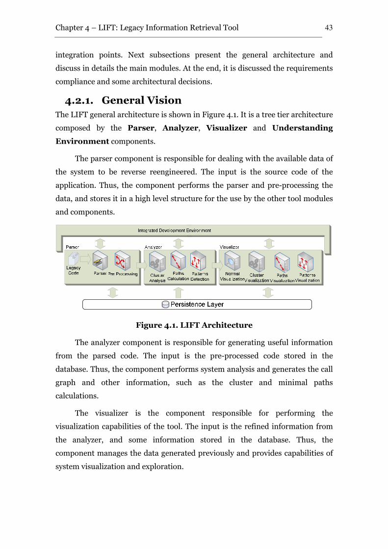
Chapter 4 – LIFT: Legacy Information Retrieval Tool
43
integration points. Next subsections present the general architecture and
discuss in details the main modules. At the end, it is discussed the requirements
compliance and some architectural decisions.
4.2.1. General Vision
The LIFT general architecture is shown in Figure 4.1. It is a tree tier architecture
composed by the Parser, Analyzer, Visualizer and Understanding
Environment components.
The parser component is responsible for dealing with the available data of
the system to be reverse reengineered. The input is the source code of the
application. Thus, the component performs the parser and pre-processing the
data, and stores it in a high level structure for the use by the other tool modules
and components.
Figure 4.1. LIFT Architecture
The analyzer component is responsible for generating useful information
from the parsed code. The input is the pre-processed code stored in the
database. Thus, the component performs system analysis and generates the call
graph and other information, such as the cluster and minimal paths
calculations.
The visualizer is the component responsible for performing the
visualization capabilities of the tool. The input is the refined information from
the analyzer, and some information stored in the database. Thus, the
component manages the data generated previously and provides capabilities of
system visualization and exploration.
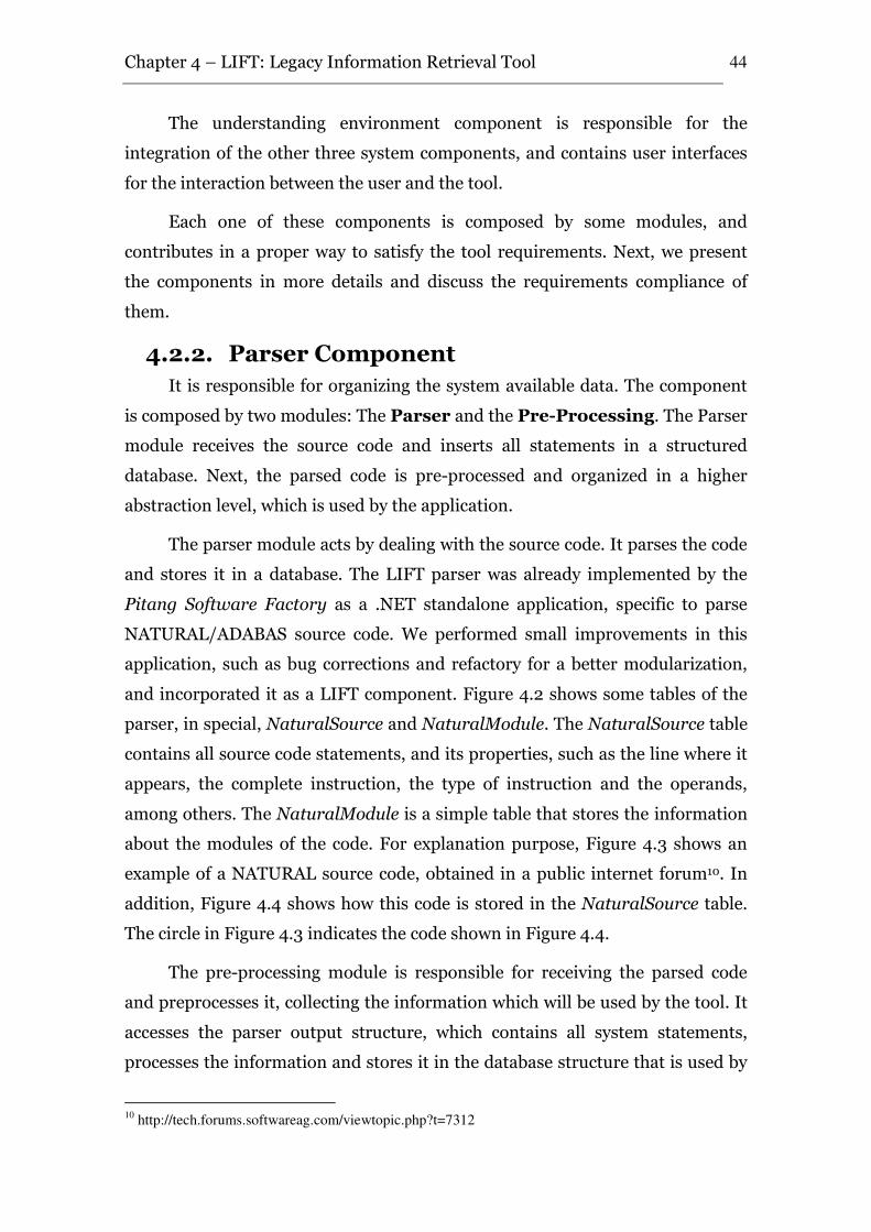
Chapter 4 – LIFT: Legacy Information Retrieval Tool
44
The understanding environment component is responsible for the
integration of the other three system components, and contains user interfaces
for the interaction between the user and the tool.
Each one of these components is composed by some modules, and
contributes in a proper way to satisfy the tool requirements. Next, we present
the components in more details and discuss the requirements compliance of
them.
4.2.2. Parser Component
It is responsible for organizing the system available data. The component
is composed by two modules: The Parser and the Pre-Processing. The Parser
module receives the source code and inserts all statements in a structured
database. Next, the parsed code is pre-processed and organized in a higher
abstraction level, which is used by the application.
The parser module acts by dealing with the source code. It parses the code
and stores it in a database. The LIFT parser was already implemented by the
Pitang Software Factory as a .NET standalone application, specific to parse
NATURAL/ADABAS source code. We performed small improvements in this
application, such as bug corrections and refactory for a better modularization,
and incorporated it as a LIFT component. Figure 4.2 shows some tables of the
parser, in special, NaturalSource and NaturalModule. The NaturalSource table
contains all source code statements, and its properties, such as the line where it
appears, the complete instruction, the type of instruction and the operands,
among others. The NaturalModule is a simple table that stores the information
about the modules of the code. For explanation purpose, Figure 4.3 shows an
example of a NATURAL source code, obtained in a public internet forum10. In
addition, Figure 4.4 shows how this code is stored in the NaturalSource table.
The circle in Figure 4.3 indicates the code shown in Figure 4.4.
The pre-processing module is responsible for receiving the parsed code
and preprocesses it, collecting the information which will be used by the tool. It
accesses the parser output structure, which contains all system statements,
processes the information and stores it in the database structure that is used by
10
http://tech.forums.softwareag.com/viewtopic.php?t=7312
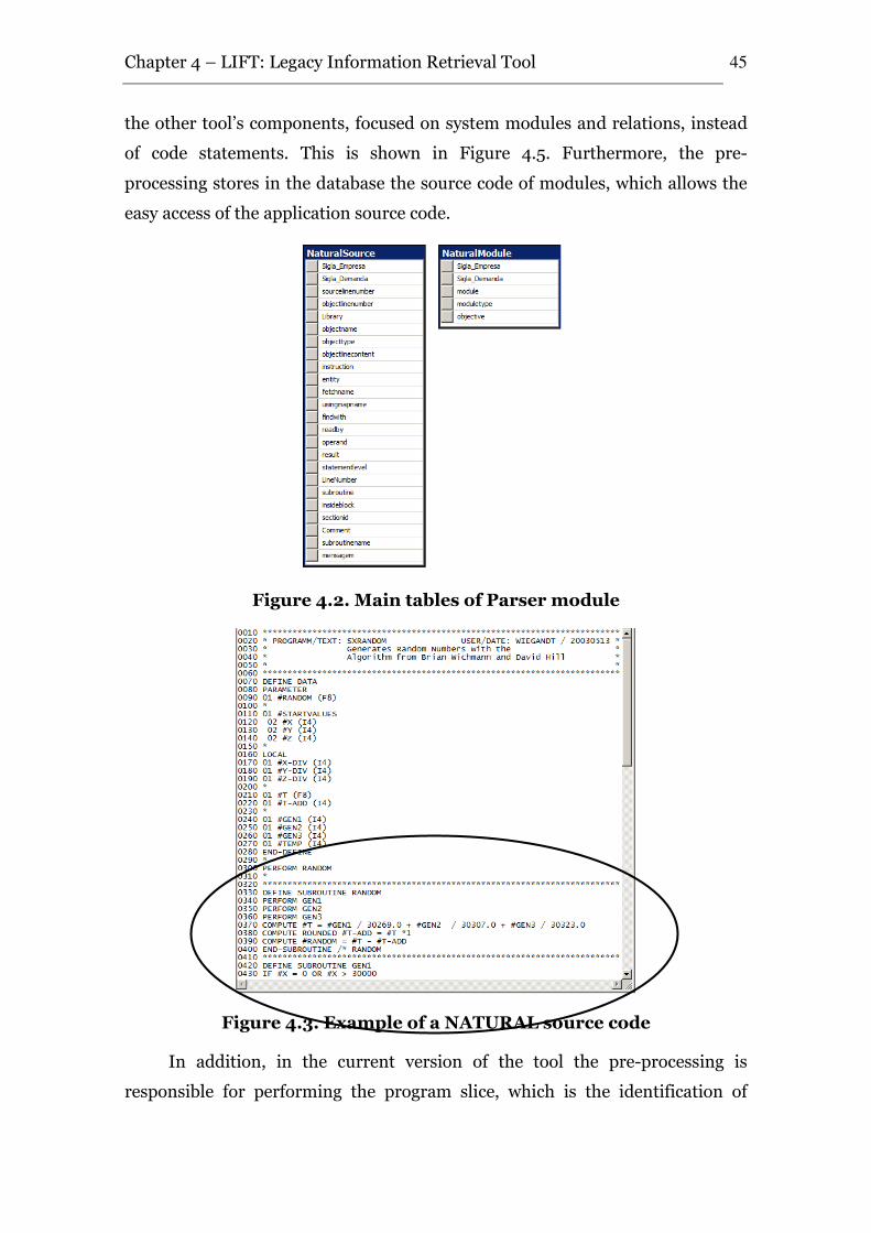
Chapter 4 – LIFT: Legacy Information Retrieval Tool
45
the other tool’s components, focused on system modules and relations, instead
of code statements. This is shown in Figure 4.5. Furthermore, the pre-
processing stores in the database the source code of modules, which allows the
easy access of the application source code.
Figure 4.2. Main tables of Parser module
Figure 4.3. Example of a NATURAL source code
In addition, in the current version of the tool the pre-processing is
responsible for performing the program slice, which is the identification of
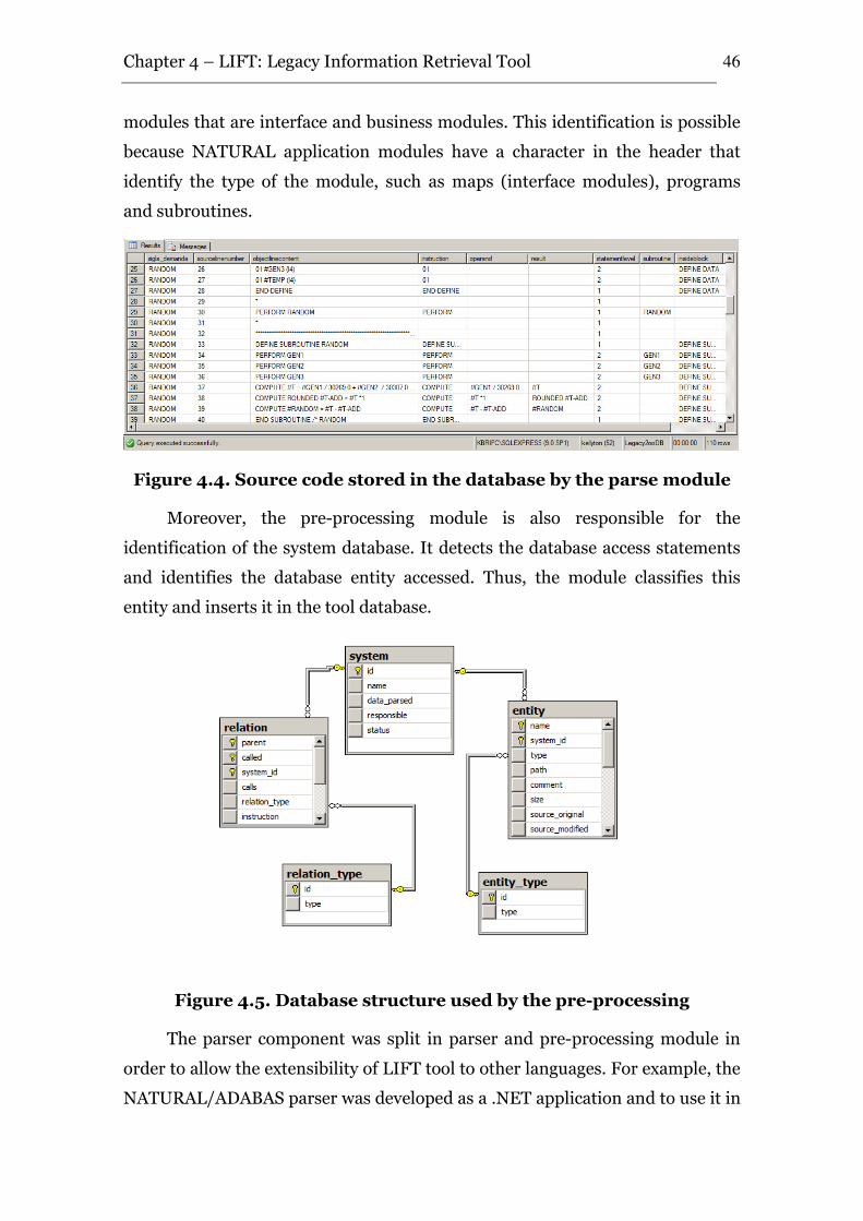
Chapter 4 – LIFT: Legacy Information Retrieval Tool
46
modules that are interface and business modules. This identification is possible
because NATURAL application modules have a character in the header that
identify the type of the module, such as maps (interface modules), programs
and subroutines.
Figure 4.4. Source code stored in the database by the parse module
Moreover, the pre-processing module is also responsible for the
identification of the system database. It detects the database access statements
and identifies the database entity accessed. Thus, the module classifies this
entity and inserts it in the tool database.
Figure 4.5. Database structure used by the pre-processing
The parser component was split in parser and pre-processing module in
order to allow the extensibility of LIFT tool to other languages. For example, the
NATURAL/ADABAS parser was developed as a .NET application and to use it in
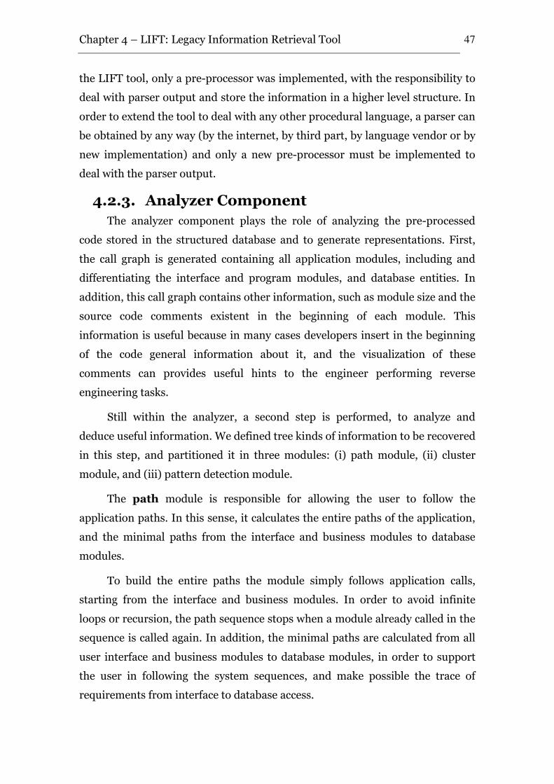
Chapter 4 – LIFT: Legacy Information Retrieval Tool
47
the LIFT tool, only a pre-processor was implemented, with the responsibility to
deal with parser output and store the information in a higher level structure. In
order to extend the tool to deal with any other procedural language, a parser can
be obtained by any way (by the internet, by third part, by language vendor or by
new implementation) and only a new pre-processor must be implemented to
deal with the parser output.
4.2.3. Analyzer Component
The analyzer component plays the role of analyzing the pre-processed
code stored in the structured database and to generate representations. First,
the call graph is generated containing all application modules, including and
differentiating the interface and program modules, and database entities. In
addition, this call graph contains other information, such as module size and the
source code comments existent in the beginning of each module. This
information is useful because in many cases developers insert in the beginning
of the code general information about it, and the visualization of these
comments can provides useful hints to the engineer performing reverse
engineering tasks.
Still within the analyzer, a second step is performed, to analyze and
deduce useful information. We defined tree kinds of information to be recovered
in this step, and partitioned it in three modules: (i) path module, (ii) cluster
module, and (iii) pattern detection module.
The path module is responsible for allowing the user to follow the
application paths. In this sense, it calculates the entire paths of the application,
and the minimal paths from the interface and business modules to database
modules.
To build the entire paths the module simply follows application calls,
starting from the interface and business modules. In order to avoid infinite
loops or recursion, the path sequence stops when a module already called in the
sequence is called again. In addition, the minimal paths are calculated from all
user interface and business modules to database modules, in order to support
the user in following the system sequences, and make possible the trace of
requirements from interface to database access.
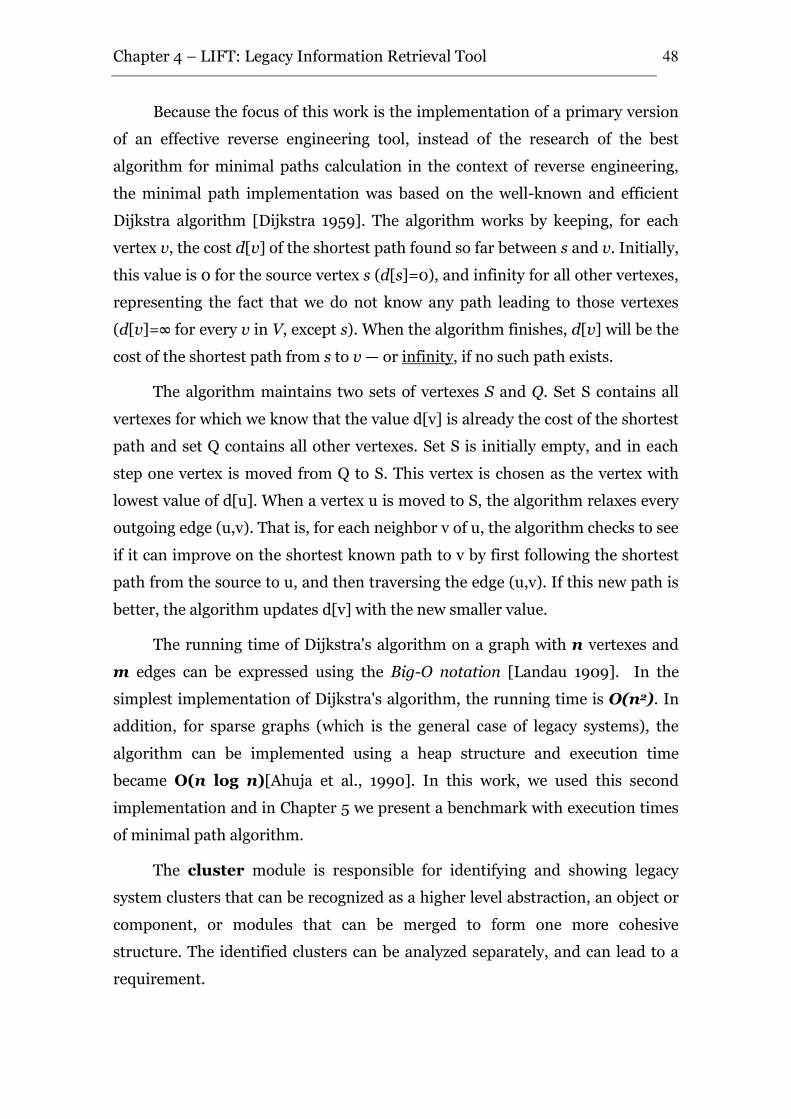
Chapter 4 – LIFT: Legacy Information Retrieval Tool
48
Because the focus of this work is the implementation of a primary version
of an effective reverse engineering tool, instead of the research of the best
algorithm for minimal paths calculation in the context of reverse engineering,
the minimal path implementation was based on the well-known and efficient
Dijkstra algorithm [Dijkstra 1959]. The algorithm works by keeping, for each
vertex v, the cost d[v] of the shortest path found so far between s and v. Initially,
this value is 0 for the source vertex s (d[s]=0), and infinity for all other vertexes,
representing the fact that we do not know any path leading to those vertexes
(d[v]=∞ for every v in V, except s). When the algorithm finishes, d[v] will be the
cost of the shortest path from s to v — or infinity, if no such path exists.
The algorithm maintains two sets of vertexes S and Q. Set S contains all
vertexes for which we know that the value d[v] is already the cost of the shortest
path and set Q contains all other vertexes. Set S is initially empty, and in each
step one vertex is moved from Q to S. This vertex is chosen as the vertex with
lowest value of d[u]. When a vertex u is moved to S, the algorithm relaxes every
outgoing edge (u,v). That is, for each neighbor v of u, the algorithm checks to see
if it can improve on the shortest known path to v by first following the shortest
path from the source to u, and then traversing the edge (u,v). If this new path is
better, the algorithm updates d[v] with the new smaller value.
The running time of Dijkstra's algorithm on a graph with n vertexes and
m edges can be expressed using the Big-O notation [Landau 1909]. In the
simplest implementation of Dijkstra's algorithm, the running time is O(n2). In
addition, for sparse graphs (which is the general case of legacy systems), the
algorithm can be implemented using a heap structure and execution time
became O(n log n)[Ahuja et al., 1990]. In this work, we used this second
implementation and in Chapter 5 we present a benchmark with execution times
of minimal path algorithm.
The cluster module is responsible for identifying and showing legacy
system clusters that can be recognized as a higher level abstraction, an object or
component, or modules that can be merged to form one more cohesive
structure. The identified clusters can be analyzed separately, and can lead to a
requirement.
Chapter 4 – LIFT: Legacy Information Retrieval Tool
49
By definition, “Cluster analysis groups data objects based only on
information found in the data that describes the objects and their
relationships. The goal is that the objects within a group be similar (or related)
to one another and different from (or unrelated to) the objects in other groups.
[Tan et al., 2006].
An entire collection of clusters is commonly referred to as a clustering, and
various types of clustering can be distinguished: hierarchical versus partitional,
exclusive versus overlapping versus fuzzy, and complete versus partial. An
partitional clustering is simply a division of the set of data objects into non-
overlapping subsets (clusters) such that each data object is in exactly one subset,
and hierarchical clustering is a set of nested clusters that are organized as a
tree, which each node (cluster) in the tree is the union of its children
(subclusters), and the root of the tree is the cluster containing all the objects; in
exclusive clustering, each object is assigned to a single cluster, while in
overlapping clustering an object can simultaneously belong to more than one
group, and in fuzzy clustering every object belongs to every cluster with a
membership weigh that is between O (absolutely doesn’t belong) and 1
(absolutely belongs); in complete clustering every object is assigned to a
clusters, whereas in partial clustering does not, many times representing noise
or outliers.
Clustering aims to find useful groups of objects (clusters), which can have
some types. A Well-Separated cluster is a set of objects in which each object is
closer (or more similar) to every other object in the cluster than to any object
not in the cluster. A Prototype-Based or Center-Based clusters is a set of
objects in which each object is closer (more similar) to the prototype (or center)
that defines the cluster than to the prototype of any other cluster. A Graph-
Based cluster is a cluster where the data is represented as a graph, where the
nodes are objects and the links represent connections among objects. In
Density-Based clusters, a cluster is a dense region of objects that is surrounded
by a region of log density. Finally, Shared-Property or Conceptual
Clusters are a set of objects that share some property.
Based on these definitions, the three cluster techniques recognized by
[Tan 2006] was studied, in order to choose a technique that produces relevant
Chapter 4 – LIFT: Legacy Information Retrieval Tool
50
results in the LIFT tool: (i) K-means, (ii) Hierarchical Clustering and (iii)
Density-based Clustering.
(i) K-means is a prototype-based, partitional clustering technique
that attempts to find a user-specified number of clusters (K),
which are represented by their centroids. This method is simple
and quite efficient, and has good results with globular clusters.
However, it cannot handle clusters of different sizes and
densities. In addition, K-means also have trouble clustering data
that contains outliers, and is restricted to data for which there is
a notion of a center.
(ii) Hierarchical Clustering techniques can be separated in (a)
agglomerative, which starts with the points as individual
clusters and, at each step, merge the closest pair of clusters, and
(b) divisive, which starts with one, all-inclusive cluster and, at
each step, split a cluster until only singleton clusters of
individual points remain. There have been some studies that
suggest that this type of algorithm can produce better-quality
clusters. Nevertheless, hierarchical clustering algorithms are
expensive in terms of their computational and storage
requirements.
(iii) Density-based techniques locate regions of high density that
are separated from one another by regions of low density. In the
traditional density, center-based approach, density is estimated
for a particular point in the data set by counting the number of
points within a specified radius of that point. Thus, clusters are
based in this density. This technique is relatively resistant to
noise and can handle clusters of arbitrary shapes and sizes. Thus,
it can find many clusters that could not be found using K-means.
Nevertheless, it has trouble when the clusters have widely
varying densities, and can be expensive when the computation of
nearest neighbors requires computing all pairwise proximities,
as is usually the case for high-dimensional data.
Chapter 4 – LIFT: Legacy Information Retrieval Tool
51
These methods were analyzed in the reverse engineering and system
comprehension context. In special, the analysis focused on good approaches to
perform graph-based clusters.
In spite of the k-means technique being used in some reverse engineering
approaches such as [Sartipi 2000], its limitations have strong impacts in cluster
detection in legacy systems. In general, legacy clusters have different sizes and
densities, with a lot of outliers, which negatively affect the quality of the clusters
identified with this technique. In addition, in most cases system’s modules
relationships not have a notion of a center, which is important to good cluster
results. Finally, k-means needs the user to choose the number of clusters (k) to
be calculated, which is difficult in the cases that the user is not familiar with the
source code. These limitations indicates that k-means is not a good technique to
identify clusters in legacy systems.
On other hand, hierarchical clusters can provide good results, but it needs
expensive computational and storage requirements, which is not desirable when
it is necessary to deal with a large amount of information, such as legacy
systems. Finally, density-based techniques are relatively resistant to noise that
occurs in legacy systems graphs, but have trouble when clusters have widely
varying densities, such as k-means techniques. In addition, this technique also
needs expensive computational requirements.
In this context, despite of its expensive computational and storage
requirements, the Hierarchical Clustering technique was chosen to perform
Graph-based cluster detection in the legacy systems call-graph, because the
characteristics of legacy systems data do not prejudice the quality of the
clusters. Thus, we chose the Mark Newman's edge betweenness clustering
algorithm [Girvan and Newman 2002]. In this algorithm, the betweenness of an
edge measures the extent to which that edge lies along shortest paths between
all pairs of nodes. Edges which are least central to communities are
progressively removed until the communities are adequately separated. We
performed a small modification in the algorithm, which is the parameterization
of the number of edges to be removed, allowing it to be interactively chosen by
user.
Chapter 4 – LIFT: Legacy Information Retrieval Tool
52
The pattern detection module was designed to perform analysis of the
code in the database and automatically detecting similarities in it, in addition to
the paths and clusters. The similarities are: (i) text pattern detection
occurred in module names or comments, which is useful to identify close
modules and highlights the name conventions of application; (ii) clone
detection occurred in source code, which is useful to highlight the “copy code”
of application, which can be isolated in a single component, and avoid repeated
work understanding the same piece of code several times; and (iii) graph
pattern detection occurred in the call graph, which highlights patterns in
application paths, providing to user best visualization of similar paths and
groups of similar functionalities.
The first version of LIFT tool prioritized the implementation of paths and
cluster detection, thus, the pattern detection module was defined but not
implemented yet.
4.2.4. Visualizer Component
The visualizer is responsible to manage the data generated by other
modules, and to present these to the user in an understandable way.
Visualization is based on the call graph generated by the analyzer component
and has four modules: (i) normal visualization, which presents the simple
call hierarchy, (ii) paths visualization, which presents options that facilitates
the comprehension of application paths, (iii) cluster visualization, which
presents options to show de clusters, and (iv) pattern visualizations, with
options to visualization detected patterns.
The normal visualization presents the call graph hierarchy using the
concepts of [Lanza and Ducasse 2003] to show additional information in the
graph. Thus, the visualization allows the user to configure modules and edges
properties of thickness, color, format and size, according to user preferences.
For example, the default visualization shows modules colors according to the
layer: blue for screen modules, green for business modules and red for database
entities. In addition, the default visualizations shows the module format
according to the count of inputs and outputs, and the number of sides is equals
of the sum of inputs and outputs. Moreover, the size of all modules is fixed by
default. Furthermore, all these options are configurable. The user can change
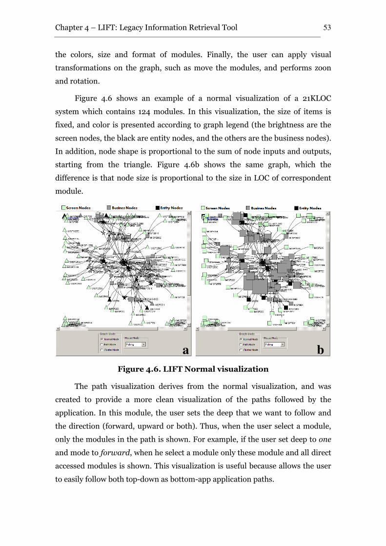
Chapter 4 – LIFT: Legacy Information Retrieval Tool
53
the colors, size and format of modules. Finally, the user can apply visual
transformations on the graph, such as move the modules, and performs zoon
and rotation.
Figure 4.6 shows an example of a normal visualization of a 21KLOC
system which contains 124 modules. In this visualization, the size of items is
fixed, and color is presented according to graph legend (the brightness are the
screen nodes, the black are entity nodes, and the others are the business nodes).
In addition, node shape is proportional to the sum of node inputs and outputs,
starting from the triangle. Figure 4.6b shows the same graph, which the
difference is that node size is proportional to the size in LOC of correspondent
module.
Figure 4.6. LIFT Normal visualization
The path visualization derives from the normal visualization, and was
created to provide a more clean visualization of the paths followed by the
application. In this module, the user sets the deep that we want to follow and
the direction (forward, upward or both). Thus, when the user select a module,
only the modules in the path is shown. For example, if the user set deep to one
and mode to forward, when he select a module only these module and all direct
accessed modules is shown. This visualization is useful because allows the user
to easily follow both top-down as bottom-app application paths.
a b
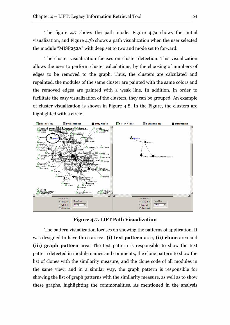
Chapter 4 – LIFT: Legacy Information Retrieval Tool
54
The figure 4.7 shows the path mode. Figure 4.7a shows the initial
visualization, and Figure 4.7b shows a path visualization when the user selected
the module “MISP252A” with deep set to two and mode set to forward.
The cluster visualization focuses on cluster detection. This visualization
allows the user to perform cluster calculations, by the choosing of numbers of
edges to be removed to the graph. Thus, the clusters are calculated and
repainted, the modules of the same cluster are painted with the same colors and
the removed edges are painted with a weak line. In addition, in order to
facilitate the easy visualization of the clusters, they can be grouped. An example
of cluster visualization is shown in Figure 4.8. In the Figure, the clusters are
highlighted with a circle.
Figure 4.7. LIFT Path Visualization
The pattern visualization focuses on showing the patterns of application. It
was designed to have three areas: (i) text pattern area, (ii) clone area and
(iii) graph pattern area. The text pattern is responsible to show the text
pattern detected in module names and comments; the clone pattern to show the
list of clones with the similarity measure, and the clone code of all modules in
the same view; and in a similar way, the graph pattern is responsible for
showing the list of graph patterns with the similarity measure, as well as to show
these graphs, highlighting the commonalities. As mentioned in the analysis
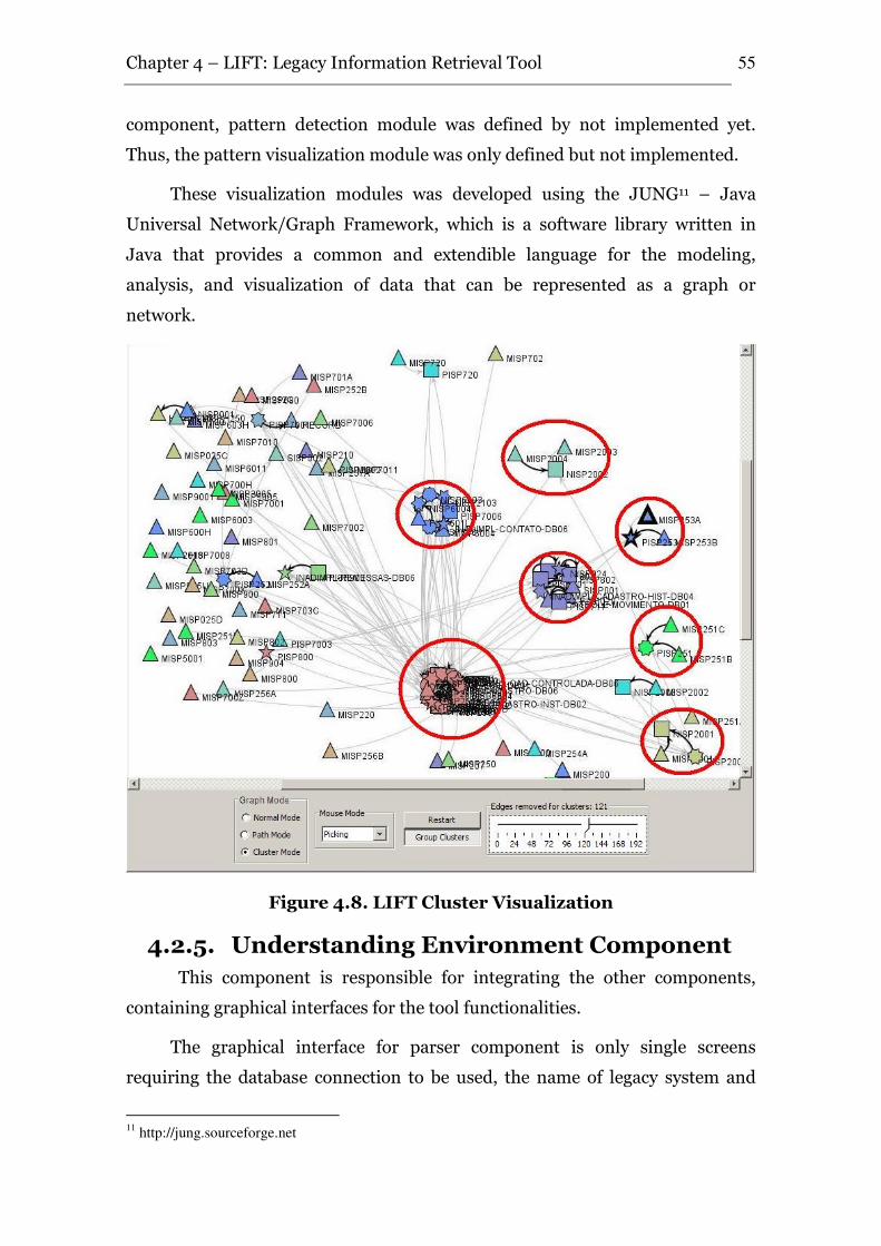
Chapter 4 – LIFT: Legacy Information Retrieval Tool
55
component, pattern detection module was defined by not implemented yet.
Thus, the pattern visualization module was only defined but not implemented.
These visualization modules was developed using the JUNG11 – Java
Universal Network/Graph Framework, which is a software library written in
Java that provides a common and extendible language for the modeling,
analysis, and visualization of data that can be represented as a graph or
network.
Figure 4.8. LIFT Cluster Visualization
4.2.5. Understanding Environment Component
This component is responsible for integrating the other components,
containing graphical interfaces for the tool functionalities.
The graphical interface for parser component is only single screens
requiring the database connection to be used, the name of legacy system and
11
http://jung.sourceforge.net
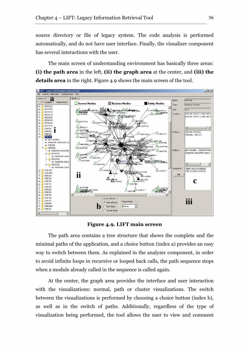
Chapter 4 – LIFT: Legacy Information Retrieval Tool
56
source directory or file of legacy system. The code analysis is performed
automatically, and do not have user interface. Finally, the visualizer component
has several interactions with the user.
The main screen of understanding environment has basically three areas:
(i) the path area in the left, (ii) the graph area at the center, and (iii) the
details area in the right. Figure 4.9 shows the main screen of the tool.
Figure 4.9. LIFT main screen
The path area contains a tree structure that shows the complete and the
minimal paths of the application, and a choice button (index a) provides an easy
way to switch between them. As explained in the analyzer component, in order
to avoid infinite loops in recursive or looped back calls, the path sequence stops
when a module already called in the sequence is called again.
At the center, the graph area provides the interface and user interaction
with the visualizations: normal, path or cluster visualizations. The switch
between the visualizations is performed by choosing a choice button (index b),
as well as in the switch of paths. Additionally, regardless of the type of
visualization being performed, the tool allows the user to view and comment
i
ii
iii
a
b
c
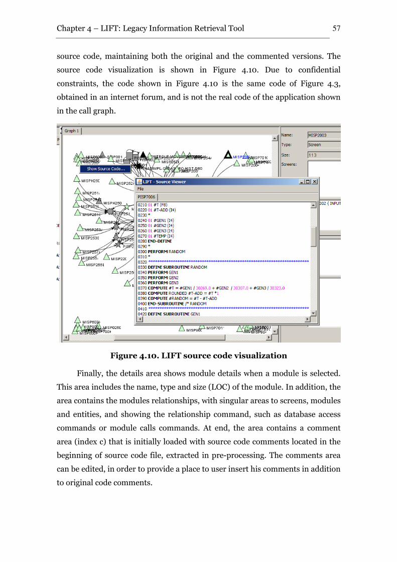
Chapter 4 – LIFT: Legacy Information Retrieval Tool
57
source code, maintaining both the original and the commented versions. The
source code visualization is shown in Figure 4.10. Due to confidential
constraints, the code shown in Figure 4.10 is the same code of Figure 4.3,
obtained in an internet forum, and is not the real code of the application shown
in the call graph.
Figure 4.10. LIFT source code visualization
Finally, the details area shows module details when a module is selected.
This area includes the name, type and size (LOC) of the module. In addition, the
area contains the modules relationships, with singular areas to screens, modules
and entities, and showing the relationship command, such as database access
commands or module calls commands. At end, the area contains a comment
area (index c) that is initially loaded with source code comments located in the
beginning of source code file, extracted in pre-processing. The comments area
can be edited, in order to provide a place to user insert his comments in addition
to original code comments.
Chapter 4 – LIFT: Legacy Information Retrieval Tool
58
The three areas are integrated. When a user chooses a module in the path
area, it is selected in the graph area and its details are shown in the details area.
In the same mode, when the user selects a module in the graph area, it is
selected in the path area and its details are shown in the details area.
Moreover, the tool works with the concept of code views. Thus, users can
generate and deal in parallel with new subgraphs from previous graphs. The
environment allows, for instance, the creation of graphs with only unconnected
modules, which in general are dead code or batch programs. Other option is to
generate new graphs with the detected clusters, isolating them from the
complete application. These views are useful to isolate modules and paths that
identify application requirements, and have an area that permits to the user
document the view, with the insertion of view name and view details.
In addition, the component has search capabilities. Since the source code
is stored in database, the understanding environment uses its capabilities to
perform search in the view and module comments, in the original source code
and in the modified code.
4.2.6. Summary of Architecture and Implementation
This Section presented the architecture and implementation details of
LIFT. The tool is a three-tier client-server application developed mainly in
JAVA. It has four major components (parser, analyzer, visualizer and
understanding environment), each one with a couple of modules.
The persistence layer uses SQL ANSI statements, therefore it is database
independent. The parser was already developed by the Pitang Software Factory
as a .NET12 standalone application, and was refined and improved to be
incorporated in LIFT and be the parser component. Currently it contains 2460
lines of code spread in 4 source files.
All other modules were developed in JAVA 1.513. Cluster analysis was
developed based on Mark Newman's edge betweenness clustering algorithm and
12
http://www.microsoft.com/msdn 13
http://java.sun.com/
Chapter 4 – LIFT: Legacy Information Retrieval Tool
59
Minimal Paths was based on Dijkstra algorithm. The Visualizer uses the JUNG,
Java Universal Network/Graph Framework, to implement visualizations.
The JAVA implementation of LIFT contains 76 classes, with 787
methods, divided into 25 packages, containing almost 10.000 line of code (not
including code comments). Next, we discuss the requirements compliance of the
tool.
4.2.7. Requirements Compliance
LIFT architecture was defined to be compliant with the requirements
identified in previous chapter. Initially, the architecture was defined aiming
reusability and maintainability (Requirement NF5), being composed by
independent components and modules with well defined interfaces. The main
components are: (i) Parser, (ii) Analyzer, (iii) Visualizer and (iv) Understanding
Environment.
The parser component is composed by two independent modules,
responsible respectively for the parser and pre-processing. The parser module
can be developed to deal with the target language, or an already developed
parser can be attached to the tool. This capability allows an easy use of the tool
with several technologies, since the use of a different input language can be
achieved only by changing the parser module and extending the pre-processor
to deal with the parser output. Thus, these capabilities accomplish the
extensibility (NF2) and integration with other tools (NF3) requirements. In
special, for a tool to be used as a parser by LIFT, it only needs a pre-processor to
read its output and to store the information needed by LIFT in the database, or
the tool itself can store these information, which is basically information about
the modules and relations, in the database. Furthermore, the tool is not
restricted to source code. The parser and pre-processor can be extended to deal
with other kinds of artifacts, such as documents and domain analysis artifacts,
in order to support a “sandwich” approach [Frakes et al., 1998], with both top-
down and bottom-up activities, satisfying the cross artifact support
requirement (NF1). In addition, the storage of source code information in a
database system, instead of maintaining information in memory, is a
fundamental item to accomplish the scalability requirement (NF4), because it
permits access to source information in a dedicate server. Furthermore, the size
Chapter 4 – LIFT: Legacy Information Retrieval Tool
60
of system does not have impact on the tool, due to the fact that database systems
have special capabilities to deal with large data amounts. Finally, the access to a
pre-processed data instead of the structure with all source code statements
collaborates to reduce computational effort in database accesses and increasing
the scalability (NF4).
The analyzer component identifies the system database structure and
classifies the application modules in interface and business modules,
accomplishing the requirement of the recovery of the entire system (interface,
design and database) (FR7). In addition, the trace of requirements from
interface to database access (F8)(F5) is accomplished by the capabilities of
minimal path calculations and path generations, and the cluster detection
allows the possibility of semi-automatic suggestions (F9).
The visualizer component shows the call graph structure, allowing the
visualization of entities and relations (F1). It also provides the possibility of
system visualization and exploration. It shows the call graph with metrics
support (F6). Furthermore, it has options to show the system in three manners:
normal, path mode and cluster mode; and provides to the user options to
configure and interact with the system in each mode (F3). Finally, the
understanding environment component integrates the other components,
providing the visualizations, user interactivity, creation of views (F2, F3, F5)
and search capabilities (F4).
In spite of some items are not implemented yet, such as the pattern
detection module, LIFT architecture and implementation fulfill all defined
requirements.
In order to better explain the tool functionalities, the next section
describes one scenario of use of the tool.
4.3. LIFT Usage
This section presents LIFT from a user’s point of view. First the code
(previously illustrated is Figure 4.3) is parsed and inserted in the database
(Figure 4.4), by the call of a menu command. The Parser screen is shown in
Figure 4.11.
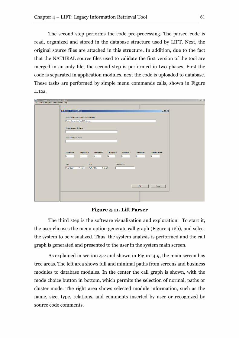
Chapter 4 – LIFT: Legacy Information Retrieval Tool
61
The second step performs the code pre-processing. The parsed code is
read, organized and stored in the database structure used by LIFT. Next, the
original source files are attached in this structure. In addition, due to the fact
that the NATURAL source files used to validate the first version of the tool are
merged in an only file, the second step is performed in two phases. First the
code is separated in application modules, next the code is uploaded to database.
These tasks are performed by simple menu commands calls, shown in Figure
4.12a.
Figure 4.11. Lift Parser
The third step is the software visualization and exploration. To start it,
the user chooses the menu option generate call graph (Figure 4.12b), and select
the system to be visualized. Thus, the system analysis is performed and the call
graph is generated and presented to the user in the system main screen.
As explained in section 4.2 and shown in Figure 4.9, the main screen has
tree areas. The left area shows full and minimal paths from screens and business
modules to database modules. In the center the call graph is shown, with the
mode choice button in bottom, which permits the selection of normal, paths or
cluster mode. The right area shows selected module information, such as the
name, size, type, relations, and comments inserted by user or recognized by
source code comments.
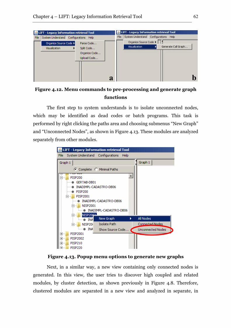
Chapter 4 – LIFT: Legacy Information Retrieval Tool
62
Figure 4.12. Menu commands to pre-processing and generate graph
functions
The first step to system understands is to isolate unconnected nodes,
which may be identified as dead codes or batch programs. This task is
performed by right clicking the paths area and choosing submenus “New Graph”
and “Unconnected Nodes”, as shown in Figure 4.13. These modules are analyzed
separately from other modules.
Figure 4.13. Popup menu options to generate new graphs
Next, in a similar way, a new view containing only connected nodes is
generated. In this view, the user tries to discover high coupled and related
modules, by cluster detection, as shown previously in Figure 4.8. Therefore,
clustered modules are separated in a new view and analyzed in separate, in
a b
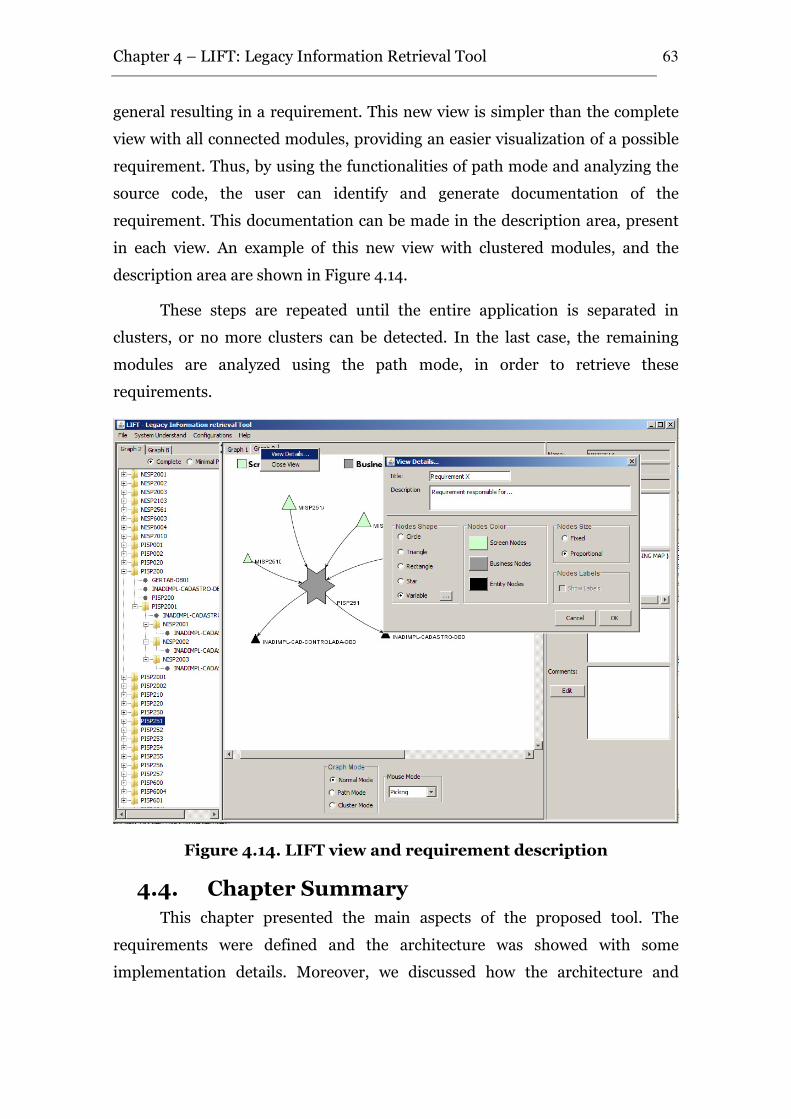
Chapter 4 – LIFT: Legacy Information Retrieval Tool
63
general resulting in a requirement. This new view is simpler than the complete
view with all connected modules, providing an easier visualization of a possible
requirement. Thus, by using the functionalities of path mode and analyzing the
source code, the user can identify and generate documentation of the
requirement. This documentation can be made in the description area, present
in each view. An example of this new view with clustered modules, and the
description area are shown in Figure 4.14.
These steps are repeated until the entire application is separated in
clusters, or no more clusters can be detected. In the last case, the remaining
modules are analyzed using the path mode, in order to retrieve these
requirements.
Figure 4.14. LIFT view and requirement description
4.4. Chapter Summary
This chapter presented the main aspects of the proposed tool. The
requirements were defined and the architecture was showed with some
implementation details. Moreover, we discussed how the architecture and
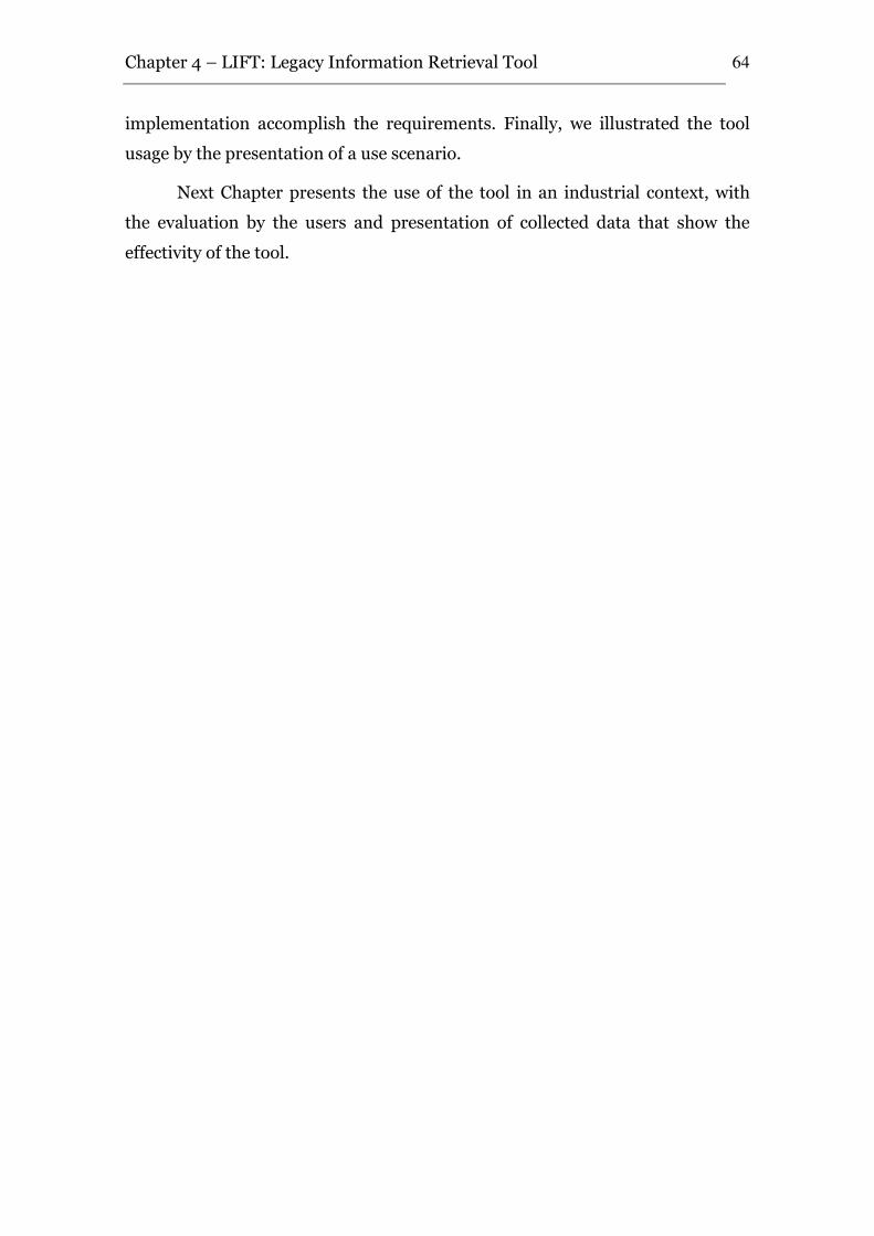
Chapter 4 – LIFT: Legacy Information Retrieval Tool
64
implementation accomplish the requirements. Finally, we illustrated the tool
usage by the presentation of a use scenario.
Next Chapter presents the use of the tool in an industrial context, with
the evaluation by the users and presentation of collected data that show the
effectivity of the tool.
LIFT Evaluation
This dissertation presented LIFT – Legacy InFormation retrieval Tool, a
tool that focuses on helping reverse engineering and system understanding.
However, an important consideration about software tools or theories is how to
measure their effectiveness. In the context of reverse engineering and system
understanding, since there is no agreed-upon definition or test of understanding
[Clayton 1998], it is difficult to claim that program understanding has been
improved when program understanding itself cannot be measured.
Despite this difficulty, it is generally agreed that more effective tools could
reduce the amount of time that maintainers need to spend understanding
software or that these tools could improve the quality of the programs that are
being maintained [Müller 2000]. However, Canfora [Canfora and Penta 2007]
recognized that better empirical evidence is a key factor to achieve the industry
adoption of reverse engineering tools.
In this context, we performed an evaluation of LIFT tool, in order to verify
if its adoption actually provides an effort reduction in reverse engineering and
system understanding tasks. This chapter presents the LIFT context, some
software evaluation techniques, and LIFT evaluation with the technique chosen,
including the results and lessons learned.
5.1 LIFT Context
As described in Chapter 4, LIFT is being developed in a context involving
both academy and industry. Its requirements and architecture definition,
implementation and evaluation were performed in conjunction with the RiSE
group, C.E.S.A.R and Pitang Software Factory. Next, LIFT was evaluated in the
context of Pitang.
Pitang has acquired experience on reverse engineering and system
understanding and retrieving knowledge from 1.6 million LOC of
5
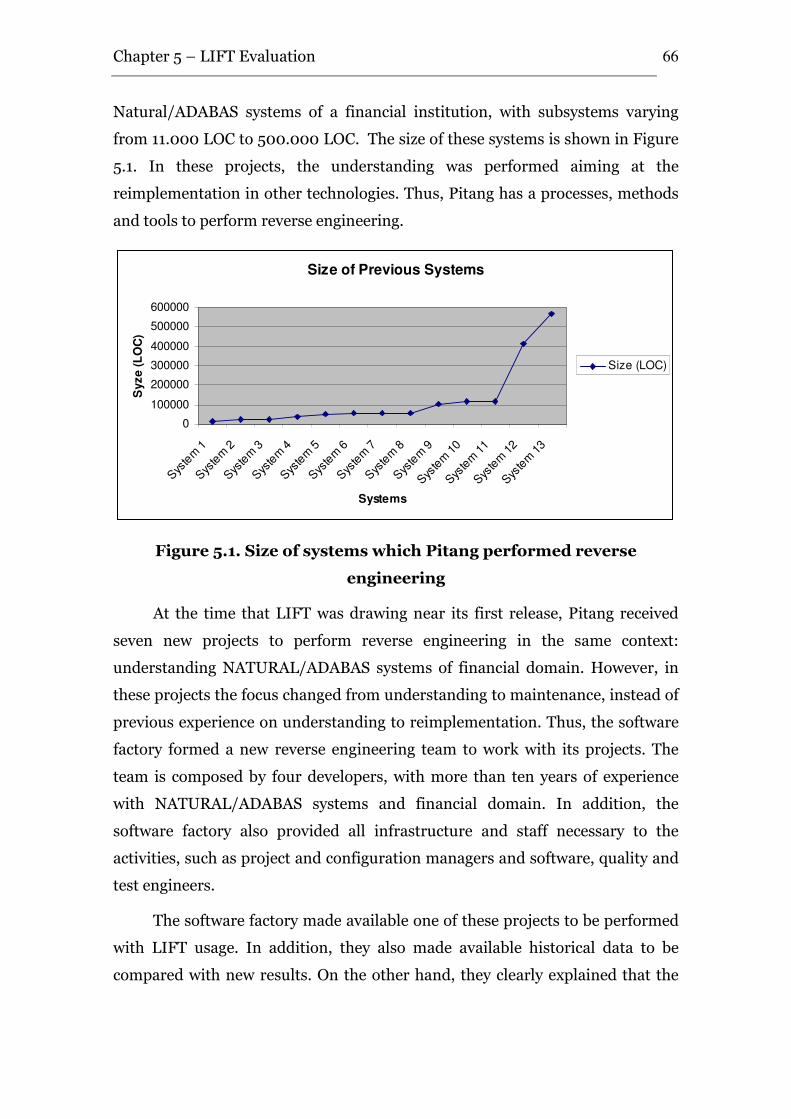
Chapter 5 – LIFT Evaluation
66
Natural/ADABAS systems of a financial institution, with subsystems varying
from 11.000 LOC to 500.000 LOC. The size of these systems is shown in Figure
5.1. In these projects, the understanding was performed aiming at the
reimplementation in other technologies. Thus, Pitang has a processes, methods
and tools to perform reverse engineering.
Size of Previous Systems
0
100000
200000
300000
400000
500000
600000
Sys
tem 1
Sys
tem 2
Sys
tem 3
Sys
tem 4
Sys
tem 5
Sys
tem 6
Sys
tem 7
Sys
tem 8
Sys
tem 9
Sys
tem 1
0
Sys
tem 1
1
Sys
tem 1
2
Sys
tem 1
3
Systems
Syze (
LO
C)
Size (LOC)
Figure 5.1. Size of systems which Pitang performed reverse
engineering
At the time that LIFT was drawing near its first release, Pitang received
seven new projects to perform reverse engineering in the same context:
understanding NATURAL/ADABAS systems of financial domain. However, in
these projects the focus changed from understanding to maintenance, instead of
previous experience on understanding to reimplementation. Thus, the software
factory formed a new reverse engineering team to work with its projects. The
team is composed by four developers, with more than ten years of experience
with NATURAL/ADABAS systems and financial domain. In addition, the
software factory also provided all infrastructure and staff necessary to the
activities, such as project and configuration managers and software, quality and
test engineers.
The software factory made available one of these projects to be performed
with LIFT usage. In addition, they also made available historical data to be
compared with new results. On the other hand, they clearly explained that the
Chapter 5 – LIFT Evaluation
67
experiment cannot negatively affect the team productivity, due to time and
budget constraints.
In this context, in order to perform LIFT evaluation, we studied some
evaluation techniques, presented next.
5.2 Software Evaluation Techniques
In a recent work [Sjoberg et al., 2007], Sjoberg classified the methods for
empirical studies in four groups. There are: (i) experimentation, (ii) surveys,
(iii) case studies, and (iv) action research.
Experimentation. An experiment is an empirical inquiry that
investigates causal relations and processes. The identification of causal relations
provides an explanation of why a phenomenon occurred, while the
identification of casual processes yields an account of how a phenomenon
occurred. Experiments are conducted when the investigator wants control over
the situation, with direct, precise, and systematic manipulation of the behavior
of the phenomenon to be studied. Thus, its most important application is in
testing theories and hypotheses.
Surveys. A survey is a retrospective study of a situation that investigates
relationships and outcomes. It is useful for studying a large number of variables
using a large sample size and rigorous statistical analysis. Surveys are especially
well-suited for answering questions about what, how much, and how many, as
well as questions about how and why. They are used when control of the
independent and dependent variables is not possible or not desirable, when the
phenomena of interest must be studied in their natural setting, and when the
phenomena of interest occur in current time or the recent past.
Action research. Action research focuses particularly on combining
theory and practice. It attempts to provide practical value to the client
organization while simultaneously contributing to the acquisition of new
theoretical knowledge. It can be characterized as an iterative process involving
researchers and practitioners acting together on a particular cycle of activities,
including problem diagnosis, action intervention, and reflective learning. The
major strength of action research is, thus, the in-depth and first-hand
understanding the researcher obtains. Its weakness is the potential lack of
Chapter 5 – LIFT Evaluation
68
objectivity on the part of the researchers when they attempt to secure a
successful outcome for the client organization.
Case Studies. A case study is an empirical inquiry that investigates a
contemporary phenomenon within its real-life context, especially when the
boundaries between phenomenon and context are not clearly evident. So, while
an experiment deliberately divorces a phenomenon from its context and a
survey’s ability to investigate the context is limited, the case study aims
deliberately at covering the contextual conditions. In addition, for Software
Engineering case studies are also useful in answering a “which is better”
question [Kitchenham et al., 1995].
The context of LIFT evaluation was presented in the Section 5.1. In this
context, we do not have control over the situation, thus performs a
experimentation could provide representative results. In addition, we do not
have a large sample size, therefore a survey is not applicable. Furthermore, the
action research involves all software life cycle, and has a potential lack of
objectivity. Thus, due to the fact that case studies investigate a phenomenon
within its real-life context, it is best suitable for LIFT evaluation context, and
was chosen to be the evaluation method.
5.3 LIFT Evaluation
The plan of this case study follows the model proposed in [Wohlin et al.,
2000] and organization adopted in [Barros 2001]. According to [Wohlin 2000],
the process can be divided into main activities. The definition defines the
experiment in terms of problem, objectives and goals. The planning defines
the design of experiment, the instrumentation and the threats to the experiment
are evaluated. The operation monitors the case study against the plan and
collects measurements, which are analyzed and evaluated in the analysis and
interpretation. Finally, the results are presented and packaged in the
presentation and package.
5.3.1 The Definition
In order to define the case study, the GQM paradigm [Basili et al., 1994]
was used to formulate the goal of the study, the questions to be answered, and
the related metrics that must be collected to answer the questions.
Chapter 5 – LIFT Evaluation
69
Goal:
According to the paradigm, the main objective of this study is:
To analyze the reverse engineering tool for the purpose of evaluating it
with respect to the efficiency of the tool from the point of view of researchers
and software engineers in the context of software reverse engineer projects.
Questions:
In addition, the questions to be answers are:
Q1. Does the tool provide effort reduction in reverse engineering
projects?
Q2. Does the tool is scalable to be used in large projects?
Metrics:
M1. Productivity: P1 - The amount of lines of code that is understood in
one work hour; P2 - The amount of program modules that is understood in one
work hour; P3 - The amount of high level requirements that is understood in
one work hour.
M2. Scalability: The relation between the increment of source code
sizes’ and the increment of time that LIFT consumes to performs a task.
5.3.2 The Planning
In their landmark paper, Basili et al. [Basili et al., 1986] emphasize that
organizations undertaking experiments should prepare an evaluation plan. This
plan identifies all the issues to be addressed so that the evaluation runs
smoothly, including the training requirements, the necessary measures, the
data-collection procedures, and the people responsible for data collection and
analysis. In addition, the evaluation should also have a budget, schedule, and
staffing plan separate from those of the actual project. Finally, clear lines of
authority are needed for resolving the inevitable conflicts of interest that occur
when a development project is used to host an evaluation exercise.
Thus, we planned the case study as follows. The planning will be
described in the future tense, showing the logic sequence between the planning
and operation.
Chapter 5 – LIFT Evaluation
70
Context. The objective of this study is to evaluate the viability of using
the LIFT tool in reverse engineering projects. The reverse engineering project
will be conduced in a software factory in an industrial context of reverse
engineering a financial application. The software factory is experienced with
reverse engineering projects, with almost 2 million LOC reverse engineered in
2006 year. Thus, it has its proper process, staff and tools to perform reverse
engineering. In special, the tools used are the common NATURAL/DATABASE
environment capabilities.
Subjects. The subjects of the study will be the software factory staff. The
reverse engineering activities will be performed by one system engineer. The
additional roles of the process (quality engineer, configuration manager
engineer, project manager, among others) will be performed by the usual staff of
the organization.
Training. The training of the subjects will be conduced in meetings at
the organization. The training will be divided in two steps: high level meetings,
and specific training. The high level meetings will be conduced with all project
staff, from managers to engineers, and will serves to show the basis and
requirements of the tool, to acquire management and staff commitment, to
available if the experiment can produce results and to collect initial feedback of
the project team. Three meetings will be performed, with two hour each. Next, a
dedicated training program will be performed with the subject that will use the
tool. Three lectures will be performed with two hour each. In addition, two use
days will occur, when the subject will use the tool with previous reverse
engineered systems loaded.
Pilot Project. Due to the organization time and budget constraints, in
addition to the difficult to obtain a small project similar to the project to be
performed in the case study, a pilot project will not be performed. Nevertheless,
the subject will use the tool with previous project data loaded, aiming to detect
problems and improve the planned material and the tool before its use.
Instrumentation. All subjects will receive a questionnaire (QT1) on
his/her education and experience, in addition to questions about strong and
weak points of the tool. The questionnaire is showed in Appendix A.
Chapter 5 – LIFT Evaluation
71
Criteria. The focus of this study demands criteria that evaluate the real
efficiency of the tool. The criteria will be evaluated quantitatively through the
amount of effort to understand the system, related to system size in LOC, in
total number of modules, and in the quantity of requirements recovered. In
addition, the scalability of the system will be evaluated through the execution
times of tasks. Moreover, the tool will be evaluated using qualitative data from
questionnaire QT1. In addition, all quantitatively data will be compared with
two other similar projects.
Null Hypothesis. This is the hypothesis that the experimenter wants to
reject with a high significance as possible. In this study, the null hypothesis
determines that the use of LIFT tool in reverse engineering projects does not
produce benefits that justify its use and that the subjects have difficulties to use
the tool. Thus, according to the selected criteria, the following hypothesis can be
defined:
H0’: µproductivity by LOC with previous approach > µproductivity by LOC using LIFT
H0’’: µproductivity by program modules with previous approach > µproductivity by
program modules using LIFT
H0’’’: µproductivity by recovered requirement with previous approach > µproductivity
by recovered requirement using LIFT
Alternative Hypothesis. This is the hypothesis in favor of which the
null hypothesis is rejected. In this study, the alternative hypothesis determines
that the use LIFT tool in reverse engineering projects produces benefits that
justify its use. Thus, the following hypothesis can be defined.
H1: µproductivity by LOC with previous approach <= µproductivity by LOC using LIFT
H2: µproductivity by program modules with previous approach <= µproductivity by
program modules using LIFT
H3: µproductivity by recovered requirement with previous approach <= µproductivity
by recovered requirement using LIFT
Independent Variables. In a study, all variables in a process that are
manipulated and controlled are called independent variables. The independent
variables are the tool, the experience of the subjects, the technology, size and
Chapter 5 – LIFT Evaluation
72
domain of the systems to be reverse engineered, the team size and the adopted
process.
Dependent Variables. The dependent variables are the variables that
are objects of the study which are necessary to study to see the effect of the
changes in the independent variables. The dependent variables are the user
productivity and tool scalability. The productivity will be measured through the
effort to understand the system, related to its size, number of modules and
number of requirements. The scalability will be measured through relations
between system size and response times.
Qualitative Analysis. The qualitative analysis aims to evaluate the
usefulness of the tool and the quality of the material used in the study. This
analysis will be performed through questionnaire QT1.
Internal Validity. Considers whether the experimental design is able to
support conclusions on causality or correlations [Wohlin 2000]. The size of our
data will be too small to allow meaningful statistical studies, so we will adopt a
descriptive analysis.
External Validity. The external validity of the study measures its
capability to be affected by the generalization, i.e., the capability to repeat the
same study in other research groups [Wohlin 2000]. In this study, a possible
problem with external validity is the subjects’ experience, since the experience
of subjects can interfere in the productivity results.. In addition, organizational
factors can influence, such as the process used to perform the reverse engineer.
Finally, the type, the domain and the size of the projects can influence the
productivity results. Nevertheless, the external validity of the study is
considered sufficient, since it aims to evaluate the effort reduction with the use
of tool. In the study, the adopted process, the subject experience and the type
and the domain of analyzed projects were similar.
Construct Validity. Construct validity considers whether the metrics
and models used in a study are a valid abstraction of the real world under study
[Wohlin 2000]. In this study, one of the most used legacy technology and
application domain was chosen. In addition, the metrics chosen to evaluate the
tool efficiency are the metrics used in real projects, such as effort in hours, and
Chapter 5 – LIFT Evaluation
73
program size based on number of lines of codes, program modules and system
requirements.
Conclusion Validity. This validity is concerned with the relationship
between the treatment and the outcome, and determines the capability of the
study to generate conclusions [Wohlin 2000]. This conclusion will be drawn by
the use of descriptive analysis.
5.3.3 The Project used in the Case Study
The project used in the case study was to perform reverse engineering of a
NATURAL/ADABAS system for a financial institution. The reverse engineering
was performed by one system engineer. He had just the source code of the
system, without any documentation (requirements and design specification,
etc). The output is the project documentation.
5.3.4 The Instrumentation
Selection of Subjects. For the execution of the study, one system
engineer of the Pitang Software factory was selected. The selection was random,
where the first available engineer was chosen.
Data Validation. In this study, due to the fact that only one project will
use the tool, descriptive statistics will be used to analyze the data set, instead of
statistical analysis. It may be used before carrying out hypothesis testing, in
order to better understand the nature of the data and to identify abnormal or
false data points [Wohlin 2000].
Instrumentation. Before the case study can be executed, all
instruments must be ready. It includes the experimental objects, tools and the
questionnaires.
5.3.5 The Operation
Experimental Environment. The case study was conduced during
Abril-June 2007, at Pitang Sofware factory. The case study was performed
directly by one engineer, and indirectly by support team (quality engineer,
configuration manager engineer, project manager, among others).
Training. The training was performed according to plan: 6 hours of high
level meetings, divided in three meetings among three weeks; 6 hours of subject
Chapter 5 – LIFT Evaluation
74
specific training, divided in three lectures among three days; and 16 hours of
tool usage by the subject. All training meetings and lectures occurred in the
Pitang dependencies. In special, the 16 hours of tool usage was performed in the
company production environment.
The reverse engineering process. The subject used the habitual
process of the organization which was used in the two sibling projects.
Costs. Since the subject of the case study was a software engineer of
Pitang Software Factory, and the environment for execution was the
organization infra-structure, the cost for the study was basically for planning
and operating. The planning for the study was about three months. During this
period, it was developed two versions of the planning presented in this
dissertation.
As previously defined, the study was performed in three steps: initially,
high level meetings were conduced (April, 2007), next the subject was trained
(April – May, 2007), and finally, he performed the reverse engineering project
(May – June, 2007).
5.3.6 The Analysis and Interpretation
Training Analysis. The training was performed as planned. The
subjects and all people involved (Pitang reverse engineer team) considered the
training very good. They considered that the initial high level meetings were
very important, to achieve management involvement and team motivation to
use the tool, instead of traditional tools used by engineers. In addition, the
subject who directly used the tool classified the dedicated training program as
good and sufficient to the tool understanding. Finally, he considered that the
two days were essential to clarify some questions.
Quantitative Analysis. The analysis compare three projects, one that
used LIFT tool and two other similar projects. We call this project as LIFT
Project and the projects that not used the tool as Project 1 and Project 2.
As explained in the Context, the three projects are similar. They use the
same technology (NATURAL/ADABAS) and application domain (financial), and
were performed by system engineers who have almost the same experience with
both the technology and application domain. In addition, the projects are from
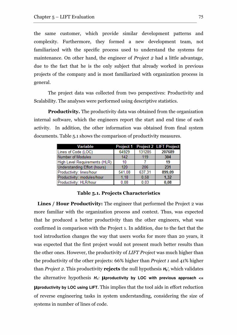
Chapter 5 – LIFT Evaluation
75
the same customer, which provide similar development patterns and
complexity. Furthermore, they formed a new development team, not
familiarized with the specific process used to understand the systems for
maintenance. On other hand, the engineer of Project 2 had a little advantage,
due to the fact that he is the only subject that already worked in previous
projects of the company and is most familiarized with organization process in
general.
The project data was collected from two perspectives: Productivity and
Scalability. The analyses were performed using descriptive statistics.
Productivity. The productivity data was obtained from the organization
internal software, which the engineers report the start and end time of each
activity. In addition, the other information was obtained from final system
documents. Table 5.1 shows the comparison of productivity measures.
Table 5.1. Projects Characteristics
Lines / Hour Productivity: The engineer that performed the Project 2 was
more familiar with the organization process and context. Thus, was expected
that he produced a better productivity than the other engineers, what was
confirmed in comparison with the Project 1. In addition, due to the fact that the
tool introduction changes the way that users works for more than 20 years, it
was expected that the first project would not present much better results than
the other ones. However, the productivity of LIFT Project was much higher than
the productivity of the other projects: 66% higher than Project 1 and 41% higher
than Project 2. This productivity rejects the null hypothesis H0’, which validates
the alternative hypothesis H1: µproductivity by LOC with previous approach <=
µproductivity by LOC using LIFT. This implies that the tool aids in effort reduction
of reverse engineering tasks in system understanding, considering the size of
systems in number of lines of code.
Chapter 5 – LIFT Evaluation
76
Modules / Hour Productivity: Instead of Project 2 has almost twice lines
of code than Project 1, the number of modules identified in Project 2 was lower
than number of modules of Project 1. It can indicate that in the analyzed
systems, there is no relation between system module number and system lines
of code. In fact, one system can have higher modularity than other, due to
several causes. Despite of these differences, the LIFT Project presented the
major number or modules identified. Additionally, the productivity of LIFT
Project concerning the effort by number of modules was higher than the
productivity of the other projects: almost 12% higher than Project 1 and 127%
higher than Project 2. This productivity rejects the null hypothesis H0’’, which
validates the alternative hypothesis H2: µproductivity by program modules with
previous approach <= µproductivity by program modules using LIFT. It reinforce that
the tool aids in effort reduction of reverse engineering tasks in system
understanding, considering the size of systems in number of modules.
High Level Requirements / Hour Productivity: Instead of Project 2 has
an almost twice line of code than Project 1, the number of high level
requirements identified in Project 2 was lower than the numbers of high level
requirements of Project 1. It can indicate that in the analyzed systems, there is
no relation between the number of requirements identified and system lines of
code. In fact, a requirement can need more lines of code to be implemented, or
design or implementation decisions can produce different implementation of
same requirement. Despite of these differences, the LIFT Project presented the
major number of high level requirements recovered. Additionally, the
productivity of LIFT Project concerning the effort by number of high level
requirements recovered was the same of Project 1 and 167% higher than Project
2. This productivity rejects the null hypothesis H0’’’, which validates the
alternative hypothesis H3: µproductivity by recovered requirement with previous
approach <= µproductivity by recovered requirement using LIFT. It indicates that the
tool aids in effort reduction of reverse engineering tasks in system
understanding, considering the number of requirements recovered.
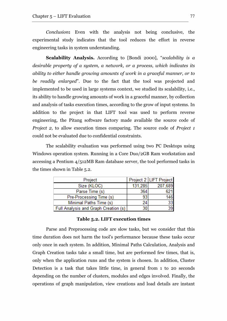
Chapter 5 – LIFT Evaluation
77
Conclusion: Even with the analysis not being conclusive, the
experimental study indicates that the tool reduces the effort in reverse
engineering tasks in system understanding.
Scalability Analysis. According to [Bondi 2000], “scalability is a
desirable property of a system, a network, or a process, which indicates its
ability to either handle growing amounts of work in a graceful manner, or to
be readily enlarged”. Due to the fact that the tool was projected and
implemented to be used in large systems context, we studied its scalability, i.e.,
its ability to handle growing amounts of work in a graceful manner, by collection
and analysis of tasks execution times, according to the grow of input systems. In
addition to the project in that LIFT tool was used to perform reverse
engineering, the Pitang software factory made available the source code of
Project 2, to allow execution times comparing. The source code of Project 1
could not be evaluated due to confidential constraints.
The scalability evaluation was performed using two PC Desktops using
Windows operation system. Running in a Core Duo/2GB Ram workstation and
accessing a Pentium 4/512MB Ram database server, the tool performed tasks in
the times shown in Table 5.2.
Table 5.2. LIFT execution times
Parse and Preprocessing code are slow tasks, but we consider that this
time duration does not harm the tool’s performance because these tasks occur
only once in each system. In addition, Minimal Paths Calculation, Analysis and
Graph Creation tasks take a small time, but are performed few times, that is,
only when the application runs and the system is chosen. In addition, Cluster
Detection is a task that takes little time, in general from 1 to 20 seconds
depending on the number of clusters, modules and edges involved. Finally, the
operations of graph manipulation, view creations and load details are instant
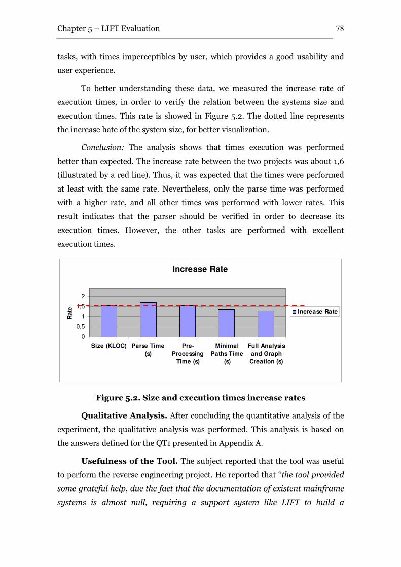
Chapter 5 – LIFT Evaluation
78
tasks, with times imperceptibles by user, which provides a good usability and
user experience.
To better understanding these data, we measured the increase rate of
execution times, in order to verify the relation between the systems size and
execution times. This rate is showed in Figure 5.2. The dotted line represents
the increase hate of the system size, for better visualization.
Conclusion: The analysis shows that times execution was performed
better than expected. The increase rate between the two projects was about 1,6
(illustrated by a red line). Thus, it was expected that the times were performed
at least with the same rate. Nevertheless, only the parse time was performed
with a higher rate, and all other times was performed with lower rates. This
result indicates that the parser should be verified in order to decrease its
execution times. However, the other tasks are performed with excellent
execution times.
Figure 5.2. Size and execution times increase rates
Qualitative Analysis. After concluding the quantitative analysis of the
experiment, the qualitative analysis was performed. This analysis is based on
the answers defined for the QT1 presented in Appendix A.
Usefulness of the Tool. The subject reported that the tool was useful
to perform the reverse engineering project. He reported that “the tool provided
some grateful help, due the fact that the documentation of existent mainframe
systems is almost null, requiring a support system like LIFT to build a
Increase Rate
0
0,5
1
1,5
2
Size (KLOC) Parse Time
(s)
Pre-
Processing
Time (s)
Minimal
Paths Time
(s)
Full Analysis
and Graph
Creation (s)
Rate Increase Rate
Chapter 5 – LIFT Evaluation
79
consistent documentation”, and that “with the LIFT tool it became easy to
generate system documentation needed to system maintenance, allowing a
better visibility to legacy system”. In addition, without having access to
comparison data, he estimated that the use of LIFT reduced in almost 20% his
effort in reverse engineering tasks. On other hand, he pointed out that the main
problem of tool is the time spent to full analysis and graph creation (in about 40
seconds). Moreover, some improvements was discussed, such as to include in
the system the reports generated by a commercial tool, and document automatic
generation from view and modules details.
Quality of the Material. The subject considered the training sufficient
for use the tool. In addition, he indicated that the presence of the experimenter
in the project context was important to encourage the tool usage, due to the
difficulty of change the way of work followed in his 22 years of activities.
Additional Qualitative Analysis. The experimenter collected
some informal user considerations about the tool.
Users agree that minimal paths visualization is very useful in knowledge
recovery for re-implementation, because the main objective is to know the main
application execution path, instead of details. However, the visualization of
complete paths is desired in knowledge recovery for maintenance, because of
the need for a map of the entire application when maintenance tasks are
performed. Additionally, they agree that the use of views to isolate possible
requirements and the existence of “Path Mode” are very useful to deal with large
systems, allowing clean visualizations of large systems.
Another important consideration is that users reported that cluster
analysis is useful to identify and isolate related modules, but the applicability of
this option was limited to identify the high level requirements groups because
the NATURAL/ADABAS environment has some features that maintain and
show to the user a list of the application entry points. However, cluster analysis
was useful to identify some of high level requirements not included in this list,
as well as clusters and sub-requirements inside them.
5.4 Lessons Learned
Chapter 5 – LIFT Evaluation
80
After concluding the experimental study, we identified some aspects that
should be considered in order to repeat the experiment, since they were seen as
limitations of the first execution.
Training. Instead of the subject claimed that the training program was
good, some lectures improvements are necessary. In addition, some questions
that still remained were clarified by the experimenter because he was allocated
in the project context. Thus, in order to eliminate the need of this allocation, an
online help should be included in the tool, and some kind of user support should
be provided, such as e-mail contact.
Questionnaire. The questionnaire should be reviewed in order to
collect more precise data related to user feedback, such as the data presented in
the Additional Qualitative Analysis. Moreover, a possible improvement can be
to collect data about specific tool requirements.
5.5 Chapter Summary
This chapter presented the LIFT evaluation context, and the definition,
planning, operation, analysis, interpretation and packaging of the case study
that evaluated the viability of the tool. The study analyzed the possibility of
subjects using the tool to achieve effort reduction in reverse engineering and
system understanding tasks. The study also analyzed the tool scalability and
usability.
Even with the reduced number of projects using the tool (one), the
analysis has shown that LIFT use can help in effort reduction of reverse
engineering and system understanding tasks. In addition, it showed that the
system is scalable to be used with larger software systems. Finally, the subject
evaluated the tool usability as good.
In addition, the study also identified some directions for improvements.
However, the study’s repetition in a different context should be considered, to
identify more points for improvements.
The next chapter will present the conclusions of this work, its main
contribution and directions for future works.
Conclusions
Software reengineering has been considered as a realistic and cost
effective way of reuse knowledge embedded in legacy systems, instead of put it
off and rebuild the systems from scratch. As discussed in Chapters 2 and 3,
there are several approaches and tools which perform reengineering and reverse
engineering, and both academy and industry are trying new ways, such as aspect
and data mining approaches. However, there are some flaws in these, in special
in recovery entire system requirements, in deal with large systems and with
tools adoption.
In this sense, in order to solve the identified problems and to reduce the
effort of reverse engineering activities, this work presented the LIFT – Legacy
InFormation retrieval Tool. The tool is based on an extensive review of
approaches and current tools, in addition to an experienced reverse engineering
group expertise.
6.1. Research Contributions
The main contributions of this work can be split into the following aspects:
i. the extension of a survey on the reengineering approaches; ii. the
presentation of a more specific survey on the state-of-the-art and practice in
software reverse engineering tools; iii. the formalization and definition of
requirements, architecture, and implementation of a reverse engineering tool;
and iv. a case study which evaluated the viability of the utilization of the tool in
a reverse engineering project.
• The Key Developments in the Field of Software
Reengineering. Initially, the goal was to understand the software
reengineering area, the origins of its concepts and ideas, processes
and methods, and future directions for research and developments,
among others, in order to obtain a big picture of the area.
6
Chapter 6 – Conclusions
82
• A Survey on Reverse Engineering Tools. Next, based on this
detailed study, the reverse engineering tools was investigated.
Through this study, eight reverse engineering tools were analyzed
and offered the base to define an initial set of requirements for an
effective reverse engineering tool.
• The LIFT – Legacy InFormation retrieval Tool. After
concluding this study, we defined the LIFT, which is a tool for
reverse engineering and system understand. The tool requirements
were based on the study and expertise of experienced groups of
reverse engineering and software reuse. Thus, the architecture was
defined and the tool implemented.
• A Case Study. In order to evaluate the tool usage viability, a case
study was performed in an industrial context. The study analyzed
the tool as quantitatively as well as qualitatively and presented
findings that the tool usage can reduce effort in reverse engineering
tasks.
6.2. Related Work
In the literature, some related work could be identified during this
research. Chapter 3 presented eight reverse engineering tools which are close to
this work. However, there are key differences between this work and the others.
Initially, this work establishes six main functional requirements that none of the
related tools supported in conjunction. In addition, we defined new
requirements not attended by any of the related tools, such as cluster analysis,
database induction and detection of minimal paths from interface to database
modules. Finally, this work achieved the scalability requirement by a new way to
deal with source code, which is its entire parse and storage in database systems,
instead of approaches that maintain a lot of data in volatile memory and harms
the tool scalability.
6.3. Future Work
Due to time constraints imposed on M.Sc dissertation, this work can be
seen as the first step towards the full vision of an efficient reverse engineering
tool. Thus, the following issues should be investigated as future work:
Chapter 6 – Conclusions
83
Plug-ins for other input languages. The current version of LIFT
supports the reverse engineering of NATURAL/ADABAS applications.
Nevertheless, it was designed to be expanded to be used with several
technologies. Thus, plug-ins should be developed containing parsers that deal
with other languages.
Automatic Documents Generation. The tool allows the creation of
system documents from view and modules description. Furthermore, it can be
extended to create these documents in an automatic way, using templates
defined by the user. In addition, a mechanism to trace the recovered documents
to the source code is desirable, in order to maintain documents always updated.
Metrics and Reports. Metrics achieve an important role in software
engineering. They allow the engineers to define quality goals, measure them,
and to monitor the accomplishment of these goals, and can be used to measure
different aspects such design and code. Thus, the definition of a set of metrics,
and reports related to its, can be helpful in reverse engineering tasks. In this
work, we used previous metrics defined by the software engineering team and
generated by a commercial tool, and these can be a starting point for definition
of reverse engineering metrics and generation the related reports in the tool.
Clone Detection. Reuse through copying and pasting source code is
common practice. So-called software clones are the results. Sometimes these
clones are modified slightly to adapt them to their new environment or purpose.
Several authors report 7 percent to 23 percent code duplication [Baker 1995],
[Kontogiannis et al., 1996], [Bruno et al., 1997]; in one extreme case, 59 percent
was reported [Ducasse et al., 1999]. Thus, if a reverse engineering tool can
automatically detect clones and prevent the user to analyze clone codes more
than once, the effort for understanding can be significantly reduced.
Case Studies. This dissertation presented the definition, planning,
operation, analysis, interpretation, presentation and packaging of a case study.
However, new studies in different context, including more subjects, other
domains and technologies are still necessary in order to calibrate the proposed
tool and the case study plan.
Chapter 6 – Conclusions
84
6.4. Academic Contributions
The knowledge developed during this work resulted in the following
publications:
• [Brito et al., 2007b] Brito, K. S.; Garcia, V. C.; Lucrédio, D.; A.;
Almeida, E. S.; Meira, S. R. L. LIFT: Reusing Knowledge from
Legacy Systems, In the Brazilian Symposium on Software
Components, Architectures and Reuse (SBCARS), Campinas, São
Paulo, Brazil, 2007.
• [Brito et al., 2007a] Brito, K. S.; Garcia, V. C.; Almeida, E. S.; Meira,
S. R. L. A Tool for Knowledge Extraction from Source Code, 21st
Brazilian Symposium on Software Engineering, Tools Session, João
Pessoa, Paraíba, Brazil, 2007.
Besides these published papers, the work presented in [Brito 2007b] was
invited to be re-submitted in a extended version to the Journal of Universal
Computer Science (JUCS), Special Issue on Software Components,
Architectures and Reuse.
6.5. Concluding Remarks
Currently, companies stand at a crossroads of competitive survival, and
information systems are no longer an additional item, but an important part of
the business, with lots of information about the business embedded in it. Thus,
the knowledge about the code is crucial for the companies, and understanding
their systems for maintenance or for technological upgrade is an essential task.
In this context, this work presented the LIFT tool for reverse engineering
and system understanding. The tool was based on an extensive review of
available reengineering approaches as well as a survey about reverse
engineering tools, in addition to a experienced group expertise. Additionally, the
tool was evaluated in an industrial project of reverse engineering 210KLOC
NATURAL/ADABAS system of a financial institution, which analyzed it both
quantitatively and qualitatively and presented findings that suggest that the tool
reduces effort in reverse engineering activities.
ppendix A. Questionnaire used
in the Case Study
QT1 – INDIVIDUAL QUESTIONNAIRE FOR THE PARTICIPANTS
OF THE EXPERIMENT
1) What is your experience in Software Development (in years)?
2) What is your experience in Reverse Engineering and legacy system
understanding projects (in years)?
3) What is your experience in the Application Domain of the application
used in the experiment (in years)?
4) What is your experience with the technology used in the experiment
(in years)?
5) What is your familiarity with the process used in the organization (use
the scale from 1 to 5, which 1 is unfamiliar, and 5 is greatly familiar)?
6) Which difficulties did you have in using the tool?
A

Appendix A - Questionnaire used in the Case Study 86
7) What do you think about the cluster detection capabilities of the tool?
8) What do you think about the minimal paths calculation of the tool?
9) What were the key points that you think that aid in the reverse
engineering tasks?
10) What difficulties did you find using the tool?
11) Which improvements would you suggest for the tool?
12) What were the biggest difficulties you had to conclude the project?
13) Could you estimate (in %) the effort reduction provided by the tool
usage?

Appendix A - Questionnaire used in the Case Study 87
14) Other comments
eferences
Ahuja, R. K., Mehlhorn, K., Orlin, J. B. and Tarjan, R. E. (1990). "Faster
Algorithms for the Shortest Path Problem." Journal of the ACM (JACM)
Vol.(37), No. 2, p. 213-223.
Almeida, E. S. (2007), "The RiSE Process for Domain Engineering", Ph.D.
Thesis, Federal University of Pernambuco, Recife, March, 2007.
Almeida, E. S., Alvaro, A., Lucrédio, D., Garcia, V. C. and Meira, S. R. d. L.
(2004). "RiSE Project: Towards a Robust Framework for Software
Reuse". IEEE International Conference on Information Reuse and
Integration (IRI), Las Vegas, USA, p. 48-53.
Alvaro, A., Almeida, E. S. and Meira, S. R. L. (2006). "A Software Component
Quality Model: A Preliminary Evaluation". 32nd IEEE EUROMICRO
Conference on Software Engineering and Advanced Applications (SEAA),
Component-Based Software Engineering Track, Cavtat/Dubrovnik,
Croatia, p. 28-35.
Alvaro, A., Lucrédio, D., Garcia, V. C., Almeida, E. S., Prado, A. F. and Trevelin,
L. C. (2003). "Orion-RE: A Component-Based Software Reengineering
Environment". 10th Working Conference on Reverse Engineering
(WCRE), Victoria - British Columbia - Canada, p. 248-257.
Aversano, L., Cimitile, A., Canfora, G. and Lucia, A. D. (2001). "Migrating
Legacy Systems application to the Web". Proceedings of 5th European
Conference on Software Maintenance and Reengineering, Lisbon,
Portugal, p. 148-157.
Baker, B. S. (1995). "On finding duplication and near-duplication in large
software systems". Proceedings of the Second Working Conference on
Reverse Engineering, IEEE Computer Society, p. 86.
R
References 89
Barros, M. O. (2001), "Project Management based on Scenarios: A Dinamic
Modeling and Simulation Approach (in portuguese)", Ph.D. Thesis,
Universidade Federal do Rio de Janeiro, 2001.
Basili, V. R., Caldiera, G. and Rombach, H. D. (1994). "The Goal Question
Metric Approach". Encyclopedia of Software Engineering, p. 528-532.
Basili, V. R., Selby, R. W. and Hutchens, D. H. (1986). "Experimentation in
Software Engineering." IEEE Transactions on Software Engineering
Vol.(12), No. 7, p. 733-743.
Bass, L., Buhman, C., Comella-Dorda, S., Long, F., Robert, J., Seacord, R. and
Wallnau, K. (2000). Market Assessment of Component-Based Software
Engineering, CMU/SEI - Carnegie Mellon University/Software
Engineering Institute. pg 41.
Bass, L., Clements, P. and Kazman, R. (1997). "Software Architecture in
Practice", Addison-Wesley.
Bayer, J. (2000). "Towards Engineering Product Lines Using Concerns".
Workshop on Multi-Dimensional Separation of Concerns in Software
Engineering (ICSE'2000), Limerick, Ireland, p. (position Paper).
Berghel, H. L. and Sallach, D. L. (1984). "Measurements of program similarity
in identical tasking environments." SIGPLAN notices Vol.(19), No. 8, p.
65-76.
Bianchi, A., Caivano, D., Marengo, V. and Visaggio, G. (2003). "Iterative
Reengineering of Legacy Systems." IEEE Transactions on Software
Engineering Vol.(29), No. 3, p. 225-241.
Bianchi, A., Caivano, D. and Visaggio, G. (2000). "Method and Process for
Iterative Reengineering of Data in a Legacy System". Proceedings of the
Seventh Working Conference on Reverse Engineering (WCRE'00),
Brisbane, Queensland, Australia, IEEE Computer Society, p. 86-97.
Bondi, A. B. (2000). "Characteristics of scalability and their impact on
performance". Proceedings of the 2nd International Workshop on
Software and Performance, Ottawa, Ontario, Canada, ACM, p. 195-203.
References 90
Boyle, J. M. and Muralidharan, M. N. (1984). "Program Reusability through
Program Transformation." IEEE Transactions on Software Engineering
Vol.(10), No. 5, p. 574-588.
Brito, K. S., Garcia, V. C., Almeida, E. S. and Meira, S. R. L. (2007a). "A Tool for
Knowledge Extraction from Source Code". 21st Brazilian Symposium on
Software Engineering (Tools Session), Campina Grande, Brazil, p. 93-99.
Brito, K. S., Garcia, V. C., Lucrédio, D. A., Almeida, E. S. and Meira, S. R. L.
(2007b). "LIFT: Reusing Knowledge from Legacy Systems". Brazilian
Symposium on Software Components, Architectures and Reuse,
Campinas, Brazil, p. 75-88.
Brooke, C. and Ramage, M. (2001). "Organisational Scenarios and Legacy
Systems." International Journal of Information Managements Vol.(21),
No., p. 365-384.
Broy, M. (2006). "The ‘Grand Challenge’ in Informatics: Engineering Software-
Intensive Systems." IEEE Computer Vol.(39), No. 10, p. 72-80.
Bruno, L., Daniel, P., Jean, M., Ettore, M. M. and John, H. (1997). "Assessing
the Benefits of Incorporating Function Clone Detection in a Development
Process". Proceedings of the International Conference on Software
Maintenance, IEEE Computer Society, p. 314.
Burégio, V. A. A. (2006), "Specification, Design, and Implementation of a Reuse
Repository", Federal University of Pernambuco, August, 2006.
Caldiera, G. and Basili, V. R. (1991). "Identifying and Qualifying Reusable
Software Components." IEEE Computer Vol.(24), No. 2, p. 61--71.
Canfora, G. and Penta, M. D. (2007). "New Frontiers of reverse Engineering".
Future of Software Engineering (FOSE), IEEE Computer Society, p. 326--
341.
Chikofsky, E. J. and Cross, J. H. (1990). "Reverse Engineering and Design
Recovery: A Taxonomy." IEEE Software Vol.(1), No. 7, p. 13-17.
Clayton, R., Rugaber, S. and Wills, L. (1998). "On the knowledge required to
understand a program". Proceedings of the 5th Working Conference on
Reverse Engineering, Honolulu, Havaii, USA, p. 69-68.
References 91
Clements, P., Bachmann, F., Bass, L., Garlan, D., Ivers, J., Little, R., Nord, R.
and Stafford, J. (2004). Documenting Software Architectures: Views and
Beyond, Addison-Wesley: 512.
Clements, P. and Northrop, L. (2001). "Software Product Lines: Practices and
Patterns", Addison-Wesley.
Demeyer, S., Tichelaar, S. and Ducasse, S. (2001). FAMIX 2.1 - The FAMOOS
information exchange model. Technical Report, University of Bern.
Dijkstra, E. W. (1959). "A note on two problems in connexion with graphs."
Numerische Mathematik Vol.(1), No. 1, p. 269-271.
Ducasse, S., Rieger, M. and Demeyer, S. (1999). "A Language Independent
Approach for Detecting Duplicated Code". Proceedings of the IEEE
International Conference on Software Maintenance, IEEE Computer
Society, p. 109.
El-Ramly, M., Stroulia, E. and Sorenson, P. (2002a). "Mining System-User
Interaction Traces for Use Case Models". Proceedings of the 10 th
International Workshop on Program Comprehension, p.
El-Ramly, M., Stroulia, E. and Sorenson, P. (2002b). Recovering software
requirements from system-user interaction traces. Proceedings of the
14th International Conference on Software Engineering and Knowledge
Engineering. Ischia, Italy, ACM Press: 447-454.
Erlikh, L. (2000). "Leveraging Legacy System Dollars for E-Business." IT
Professional Vol.(2), No. 3, p. 17-23.
Ezran, M., Morisio, M. and Tully, C. (2002). "Practical Software Reuse".
Springer, p. 374.
Favre, J.-M. (2001). "GSEE: a Generic Software Exploration Environment".
Proceedings of the International Workshop on Program Comprehension
(IWPC), Toronto, Ont., Canada, p. 233.
Frakes, W., Prieto-Diaz, R. and Fox, C. (1998). "DARE: Domain analysis and
reuse environment". Annals of Software Engineering 5, p. 125-141.
Gall, H. and Klösch, R. (1994). "Program transformation to enhance the reuse
potential of procedural software". Proceeding of the ACM Symposium on
References 92
Applied Computing (SAC'1994), Phoenix, Arizona, United States, p. 99-
104.
Garcia, V. C. (2005), "Phoenix: An Aspect Oriented Approach for Software
Reengineer(in portuguese). M.Sc Thesis." Federal University of São
Carlos, São Carlos, Brazil, March/2005.
Garcia, V. C., Lucrédio, D., Durão, F. A., Santos, E. C. R., Almeida, E. S., Fortes,
R. P. M. and Meira, S. R. L. (2006). "From Specification to the
Experimentation: A Software Component Search Engine Architecture".
9th International Symposium on Component-Based Software
Engineering (CBSE), Sweden, Lecture Notes in Computer Science
(LNCS), Springer-Verlag, p. 82-97.
Garcia, V. C., Lucrédio, D., Prado, A. F. d., Alvaro, A. and Almeida, E. (2004).
"Towards an Effective Approach for Reverse Engineering". Proceedings
of 11th Working Conference on Reverse Engineering (WCRE), Delft,
Netherlands, p. 298-299.
Girvan, M. and Newman, M. E. J. (2002). "Community Structure in Social and
Biological Networks." Proceedings of the National Academy of Sciences
of USA Vol.(99), No. 12.
Grier, S. (1981). "A tool that detects plagiarism in Pascal programs." SIGSCE
Bulletin Vol.(13), No. 1.
Harel, D. (1992). "Biting the silver bullet: toward a brighter future for system
development." IEEE Computer Vol.(25), No. 1, p. 8-20.
Heineman, G. T. and Councill, W. T. (2001). "G. T. Heineman, W. T. Councill,
Component-Based Software Engineering", Addison-Wesley.
Jacobson, I. and Lindstrom, F. (1991). Reengineering of old systems to an
object-oriented architecture. Proceedings of the Object-Oriented
Programming Systems, Languages and Applications (OOPSLA'91): 340-
350.
Kapoor, R. V. and Stroulia, E. (2001). "Mathaino: Simultaneous Legacy
Interface Migration to Multiple Platforms". 9th International Conference
on Human-Computer Interaction, New Orleans, LA, USA, p. 51-55.
References 93
Keller, R. K., Schauer, R., Robitaille, S. e. and Pag\'e, P. (1999). Pattern-based
reverse-engineering of design components. Proceedings of the 21st
International Conference on Software Engineering (ICSE'99): 226-235.
Kiczales, G., Hilsdale, E., Hugunin, J., Kersten, M., Palm, J. and Griswold, W. G.
(2001). "Getting Started with AspectJ." Communications of ACM
Vol.(44), No. 10, p. 59-65.
Kitchenham, B. A., Pickard, L. M. and Pfleeger, S. L. (1995). "Case Studies for
Method and Tool Evaluation." IEEE Software Vol.(12), No. 4, p. 52-62.
Kontogiannis, K. A., Demori, R., Merlo, E., Galler, M. and Bernstein, M. (1996).
Pattern matching for clone and concept detection. Reverse engineering,
Kluwer Academic Publishers: 77-108.
Kruchten, P., Obbink, H. and Stafford, J. (2006). "The Past, Present, and Future
of Software Architecture." IEEE Software Vol.(23), No. 02, p. 22-30.
Krueger, C. W. (1992). "Software Reuse." ACM Computing Surveys Vol.(24), No.
2, p. 131-183.
Lammel, R. and Verhoef, C. (2001). "Cracking the 500-language problem."
IEEE Software Vol.(18), No. 6, p. 78-88.
Landau, E. (1909). "Handbuch der Lehre von der Verteilung der Primzahlen".
The University of Michigan Historical Mathematics Collection, p. 908-
961.
Lanza, M. (2003). "CodeCrawler - lessons learned in building a software
visualization tool". Proceedings of European Conference on Software
Maintenance and Reengineering, p. 409-418.
Lanza, M. and Ducasse, S. p. (2003). "Polymetric Views-A Lightweight Visual
Approach to Reverse Engineering." IEEE Transactions on Software
Engineering Vol.(29), No. 9, p. 782-795.
Lee, E., Lee, B., Shin, W. and Wu, C. (2003). A Reengineering Process for
Migrating from an Object-oriented Legacy System to a Component-based
System. Proceedings of the 27th Annual International Computer
Software and Applications Conference (COMPSAC).
References 94
Lehman, M. M. (1980). "Programs, life cycles, and laws of software evolution."
Proceedings of the IEEE Vol.(68), No. 9, p. 1060 -1076.
Lehman, M. M. and Belady, L. A. (1985). "Program Evolution Processes of
Software Change", London: Academic Press.
Lientz, B. P., Swanson, E. B. and Tompkins, G. E. (1978). "Characteristics of
Application Software Maintenance." Communications of the ACM
Vol.(21), No. 6, p. 466 - 471.
Lippert, M. and Lopes, C. V. (2000). "A study on exception detecton and
handling using aspect-oriented programming". Proceedings of the 22nd
International Conference on Software Engineering (ICSM), Limerick,
Ireland, p. 418-427.
Lisboa, L. B., Garcia, V. C., Almeida, E. S. d. and Meira, S. L. (2007). "ToolDAy
A Process-Centered Domain Analysis Tool". 21st Brazilian Symposium on
Software Engineering, Tools Session, João Pessoa, Brazil, p. (to appear).
Liu, K., Alderson, A. and Qureshi, Z. (1999). "Requirements Recovery from
Legacy Systems by Analysing and Modelling Behaviour". Proceedings of
IEEE International Conference on Software Maintenance (ICSM '99), p.
Madhavji, N. H. (1985). "Compare: A Collusion Detector for Pascal." T.S.I -
Technique et Science Informatiques Vol.(4), No. 6, p. 489-498.
Mascena, J. C. C. P. (2006), "ADMIRE: Asset Development Metric-based
Integrated Reuse Environment", M.Sc. Dissertation, Federal University
of Pernambuco, May, 2006.
Mayrhauser, A. v. and Vans, A. M. (1997). "Program Understanding Needs
during Corrective Maintenance of Large Scale Software". Proceedings of
International Computer Software and Applications Conference (ICSA), p.
630-637.
McIlroy, M. D. (1968). "Mass Produced Software Components". NATO Software
Engineering Conference Report, Garmisch, Germany, p. 79-85.
Meyer, B. (1997). "Object-Oriented Software Construction", Prentice-Hall,
Englewood Cliffs.
References 95
Moore, M. M. and Moshkina, L. (2000). "Migrating Legacy User Interfaces to
the Internet: Shifiting Dialogue Initiative". Proceedings of 7ht Working
Conference on Reverse Engineering (WCRE'2000), Brisbane, Australia,
p. 52-58.
Müller, H. A., Jahnke, J. H., Smith, D. B., Storey, M.-A., Tilley, S. R. and Wong,
K. (2000). "Reverse Engineering: A Roadmap". Proceedings of the 22nd
International Conference on Software Engineering (ICSE'2000). Future
of Software Engineering Track, Limerick Ireland, p. 47-60.
Müller, H. A. and Klashinsky, K. (1988). "Rigi: a system for programming-in-
the-large". Proceedings of the 10th International Conference on Software
Engineering, Singapore, IEEE Computer Society Press, p. 80-86.
Müller, H. A., Tilley, S. R. and Wong, K. (1993). "Understanding software
systems using reverse engineering technology perspectives from the Rigi
project". Proceedings of the 1993 Conference of the Centre for Advanced
Studies on Collaborative Research, Toronto, Ontario, Canada, p. 217-226.
Neighbors, J. M. (1996). "Finding Reusable Software Components in Large
Systems". Proceedings of the 3rd Working Conference on Reverse
Engineering (WCRE '96), Monterey, CA, USA, p. 2-10.
Nierstrasz, O., Ducasse, S. and Girba, T. (2005). "The story of moose: an agile
reengineering environment." ACM SIGSOFT Software Engineering Notes
Vol.(30), No. 5, p. 1-10.
Olsem, M. R. (1998). "An incremental approach to software systems re-
engineering." Journal of Software Maintenance Vol.(10), No. 3, p. 181--
202.
Paul, S. (1992). "SCRUPLE: a reengineer's tool for source code search".
Proceedings of the 1992 Conference of the Centre for Advanced Studies
on Collaborative research, Toronto, Ontario, Canada, IBM Press, p. 329-
346
Pressman, R. S. (2001). "Software Engineering: A Practitioner's Approach",
McGraw-Hill.
References 96
Sartipi, K., Kontogiannis, K. and Mavaddat, F. (2000). "Architectural design
recovery using data mining techniques". Proceedings of the 4th European
Software Maintenance and Reengineering (ESMR), Zurich, Switzerland,
p. 129-139.
Schäfer, T., Eichberg, M., Haupt, M. and Mezini, M. (2006). "The SEXTANT
Software Exploration Tool." IEEE Transactions on Software Engineering
Vol.(32), No. 9.
Shaw, M. and Garlan, D. (1996). "Software Architecture: Perspective on an
Emerging Discipline", Prentice Hall.
Singer, J., Lethbridge, T., Vinson, N. and Anquetil, N. (1997). "An examination
of software engineering work practices". Proceedings of conference of the
Centre for Advanced Studies on Collaborative research (CASCON),
Toronto, Ontario, Canada, IBM Press, p. 21.
Sjoberg, D. I. K., Dyba, T. and Jorgensen, M. (2007). "The Future of Empirical
Methods in Software Engineering Research". Future of Software
Engineering (FOSE), IEEE Computer Society, p. 358-378.
Sneed, H. M. (1996). Object-Oriented COBOL Recycling. Proceedings of the 3rd
Working Conference on Reverse Engineering (WCRE'96): 169-178.
Sneed, M. H. and Erdos, K. (1996). "Extracting Business Rules from Source
Code". Proceedings of the Fourth Workshop on Program Comprehension,
Berlin, Germany, p. 240-247.
Sommerville, I. (2000). "Software Engineering", Pearson Education.
Standish, T. A. (1984). "An Essay on Software Reuse." IEEE Transactions on
Software Engineering Vol.(10), No. 5, p. 494-497.
Storey, M.-A. D., Fracchia, F. D. and Müller, H. A. (1999). "Cognitive design
elements to support the construction of a mental model during software
exploration." The Journal of Systems and Software Vol.(44), No.
Tan, P.-N., Steinbach, M. and Kumar, V. (2006). "Introduction to Data Mining",
Addison Wesley.
Vanderlei, T. A., Durão, F. A., Martins, A. C., Garcia, V. C., Almeida, E. S. and
Meira, S. R. L. (2007). "A Classification Mechanism for Search and
References 97
Retrieval Software Components". 22nd Annual ACM Symposium on
Applied Computing (SAC), Information Retrieval Track, Seul, Korea, p.
Ware, C. (2000). "Information Visualization", Morgan Kaufmann.
Waters, R. C. (1988). "Program Translation Via Abstraction and
Reimplementation." IEEE Transactions on Software Engineering
Vol.(14), No. 8, p. 1207-1228.
Wilkening, D. E., Loyall, J. P., Pitarys, M. J. and Littlejohn, K. (1995). "A reuse
approach to software reengineering." Journal of Systems and Software
Vol.(30), No. 1-2, p. 117-125.
Wohlin, C., Runeson, P., Host, M., Ohlsson, M. C., Regnell, B. and Wesslen, A.
(2000). "Experimentation in Software Engineering: An Introduction",
Boston MA: Kluwer Academic Publisher.
Yeh, A. S., Harris, D. R. and Reubenstein, R. (1995). Recovering Abstract Data
Types and Object Instances from a Conventional Procedural Language.
Proceedings of Second Working Conference on Reverse Engineering:
227-236.
Yeh, D. and Li, Y. (2005). "Extracting Entity Relationship Diagram from a
Table-based Legacy Database". Proceedings of the Ninth European
Conference on Software Maintenance and Reengineering (CSMR’05), p.
Zayour, I. and Lethbridge, T. C. (2000). "A cognitive and user centric based
approach for reverse engineering tool design". Proceedings of the 2000
Conference of the Centre for Advanced Studies on Collaborative
Research, Ontario, Canada, p. 16.
Zou, Y. and Kontogiannis, K. (2003). Incremental Transformation of Procedural
Systems to Object Oriented Platforms. Proceedings of the 27th Annual
International Computer Software and Applications Conference
(COMPSAC): 290-295.