Embed Size (px)
Citation preview
Page 1 of 15
Keller Limited t/a Phi Group
Montis Court Bouncers Lane Cheltenham GL52 5JG
Tel: 01242 707600 HAPAS Certificate e-mail: [email protected] 17/H269 website: www.phigroup.co.uk Product Sheet 1
PHI GROUP RETAINING STRUCTURES TITAN WALL SYSTEM FOR REINFORCED SOIL RETAINING WALLS AND BRIDGE ABUTMENTS
This HAPAS Certificate Product Sheet(1) is issued by the British Board of Agrément (BBA), supported by Highways England (HE) (acting on behalf of the Overseeing Organisations of the Department for Transport; Transport Scotland; the Welsh Assembly Government and the Department for Infrastructure, Northern Ireland), the Association of Directors of Environment, Economy, Planning and Transport (ADEPT), the Local Government Technical Advisers Group and industry bodies. HAPAS Certificates are normally each subject to a review every three years. (1) Hereinafter referred to as ‘Certificate’.
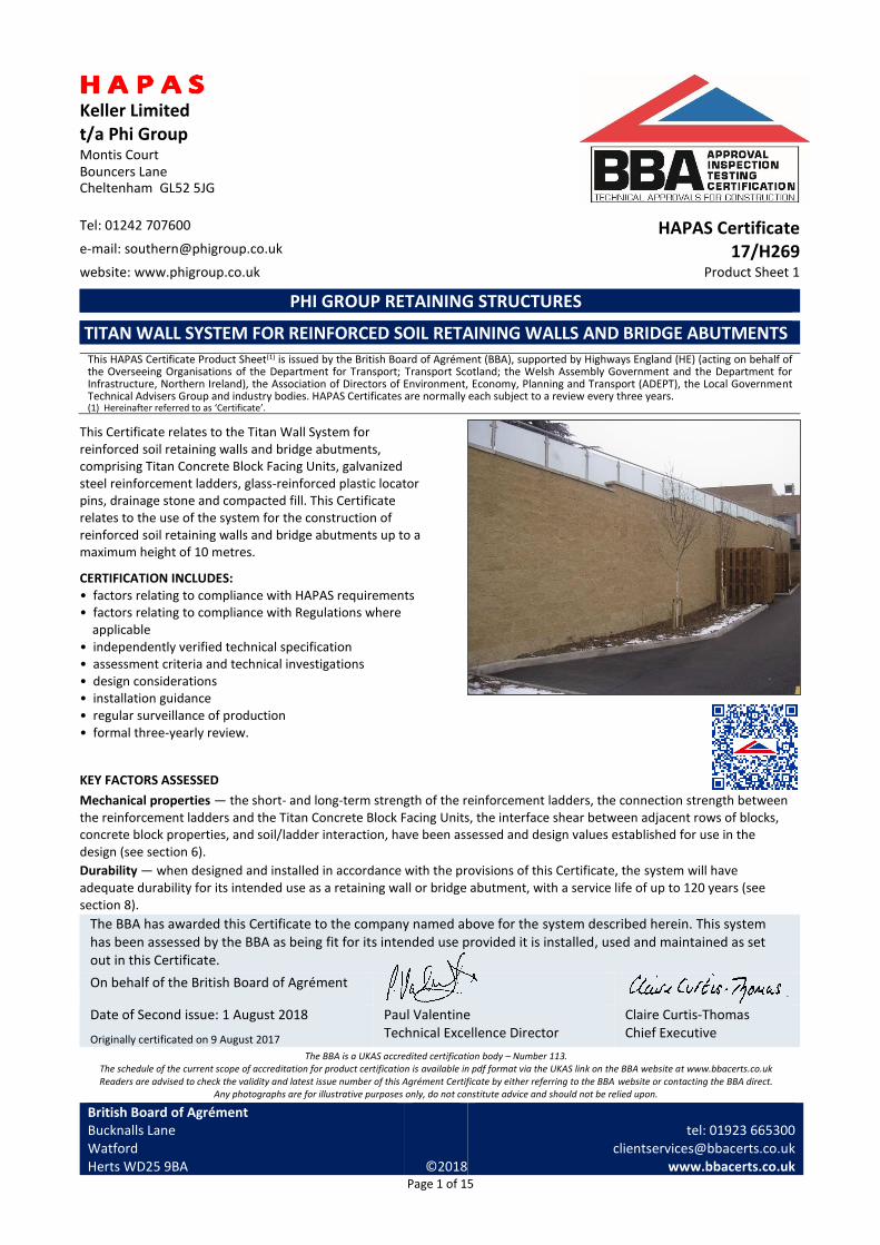
This Certificate relates to the Titan Wall System for reinforced soil retaining walls and bridge abutments, comprising Titan Concrete Block Facing Units, galvanized steel reinforcement ladders, glass-reinforced plastic locator pins, drainage stone and compacted fill. This Certificate relates to the use of the system for the construction of reinforced soil retaining walls and bridge abutments up to a maximum height of 10 metres.
CERTIFICATION INCLUDES: • factors relating to compliance with HAPAS requirements • factors relating to compliance with Regulations where
applicable • independently verified technical specification • assessment criteria and technical investigations • design considerations • installation guidance • regular surveillance of production • formal three-yearly review.
KEY FACTORS ASSESSED
Mechanical properties — the short- and long-term strength of the reinforcement ladders, the connection strength between the reinforcement ladders and the Titan Concrete Block Facing Units, the interface shear between adjacent rows of blocks, concrete block properties, and soil/ladder interaction, have been assessed and design values established for use in the design (see section 6).
Durability — when designed and installed in accordance with the provisions of this Certificate, the system will have adequate durability for its intended use as a retaining wall or bridge abutment, with a service life of up to 120 years (see section 8).
The BBA has awarded this Certificate to the company named above for the system described herein. This system has been assessed by the BBA as being fit for its intended use provided it is installed, used and maintained as set out in this Certificate.
On behalf of the British Board of Agrément
Date of Second issue: 1 August 2018
Originally certificated on 9 August 2017
Paul Valentine Technical Excellence Director
Claire Curtis-Thomas Chief Executive
The BBA is a UKAS accredited certification body – Number 113. The schedule of the current scope of accreditation for product certification is available in pdf format via the UKAS link on the BBA website at www.bbacerts.co.uk Readers are advised to check the validity and latest issue number of this Agrément Certificate by either referring to the BBA website or contacting the BBA direct.
Any photographs are for illustrative purposes only, do not constitute advice and should not be relied upon.
British Board of Agrément Bucknalls Lane Watford Herts WD25 9BA
©2018
tel: 01923 665300
[email protected] www.bbacerts.co.uk

Page 2 of 15
Requirements In the opinion of the BBA, the Titan Wall System for reinforced soil retaining walls and bridge abutments, when used in accordance with the provisions of this Certificate, will meet or contribute to meeting the requirements of the Manual of Contract Documents for Highways Works (MCHW) (1), Volume 1 Specification for Highways Works (SHW). (1) The MCHW is operated by the Overseeing Organisations: Highways England (HE), Transport Scotland, the Welsh Assembly Government and the
Department for Infrastructure (Northern Ireland).
Regulations
Construction (Design and Management) Regulations 2015 Construction (Design and Management) Regulations (Northern Ireland) 2016 Information in this Certificate may assist the client, designer (including Principal Designer) and contractor (including Principal Contractor) to address their obligations under these Regulations. See sections: 1 Description (1.2 and 1.7), 3 Delivery and site handling (3.1 to 3.4) and 11 Procedure (11.10)
of this Certificate.
Additional Information
CE marking
The supplier of the concrete blocks has taken the responsibility of CE marking the blocks in accordance with BS EN 771-3 : 2011. An asterisk (*) appearing in this Certificate indicates that data shown are given in the manufacturer’s Declaration of Performance.
Technical Specification
1 Description 1.1 The Titan Wall System for reinforced soil retaining walls and the soil retaining element of bridge abutments comprises:
• Titan Concrete Block Facing Units
• galvanized steel reinforcement ladders
• glass-reinforced plastic (GRP) locator pins
• granular material (drainage stone) — placed immediately behind the wall to provide a drainage layer
• compacted fill.
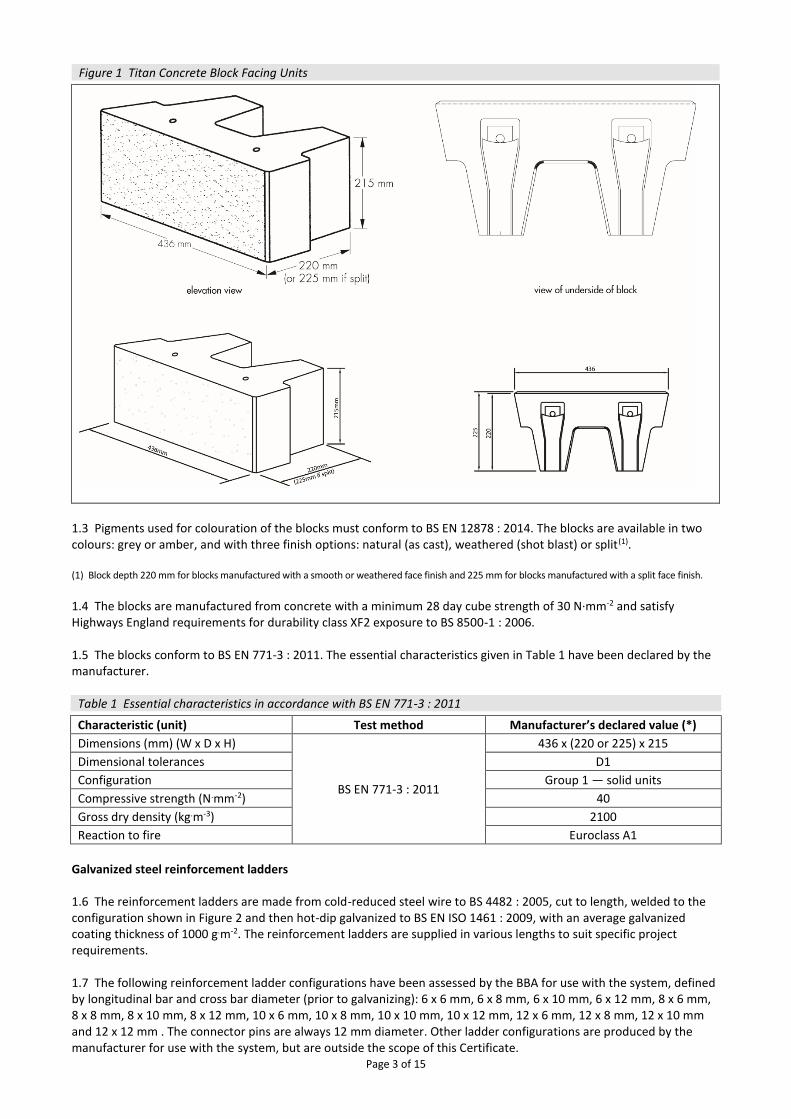
Titan Concrete Block Facing Units 1.2 Titan Concrete Block Facing Units have a height of 215 mm, a depth of 220 or 225 mm(1) and a width of 436 mm (see Figure 1). The nominal mass of each block is 29.5 kg. Each block includes two 14 mm diameter holes through the full depth of the block, for connection of the reinforcement ladders or insertion of the locator pins.
Page 3 of 15
Figure 1 Titan Concrete Block Facing Units
1.3 Pigments used for colouration of the blocks must conform to BS EN 12878 : 2014. The blocks are available in two colours: grey or amber, and with three finish options: natural (as cast), weathered (shot blast) or split(1). (1) Block depth 220 mm for blocks manufactured with a smooth or weathered face finish and 225 mm for blocks manufactured with a split face finish.
1.4 The blocks are manufactured from concrete with a minimum 28 day cube strength of 30 N·mm-2 and satisfy Highways England requirements for durability class XF2 exposure to BS 8500-1 : 2006. 1.5 The blocks conform to BS EN 771-3 : 2011. The essential characteristics given in Table 1 have been declared by the manufacturer.
Table 1 Essential characteristics in accordance with BS EN 771-3 : 2011 Characteristic (unit) Test method Manufacturer’s declared value (*)
Dimensions (mm) (W x D x H)
BS EN 771-3 : 2011
436 x (220 or 225) x 215
Dimensional tolerances D1
Configuration Group 1 — solid units
Compressive strength (N.mm-2) 40
Gross dry density (kg.m-3) 2100
Reaction to fire Euroclass A1
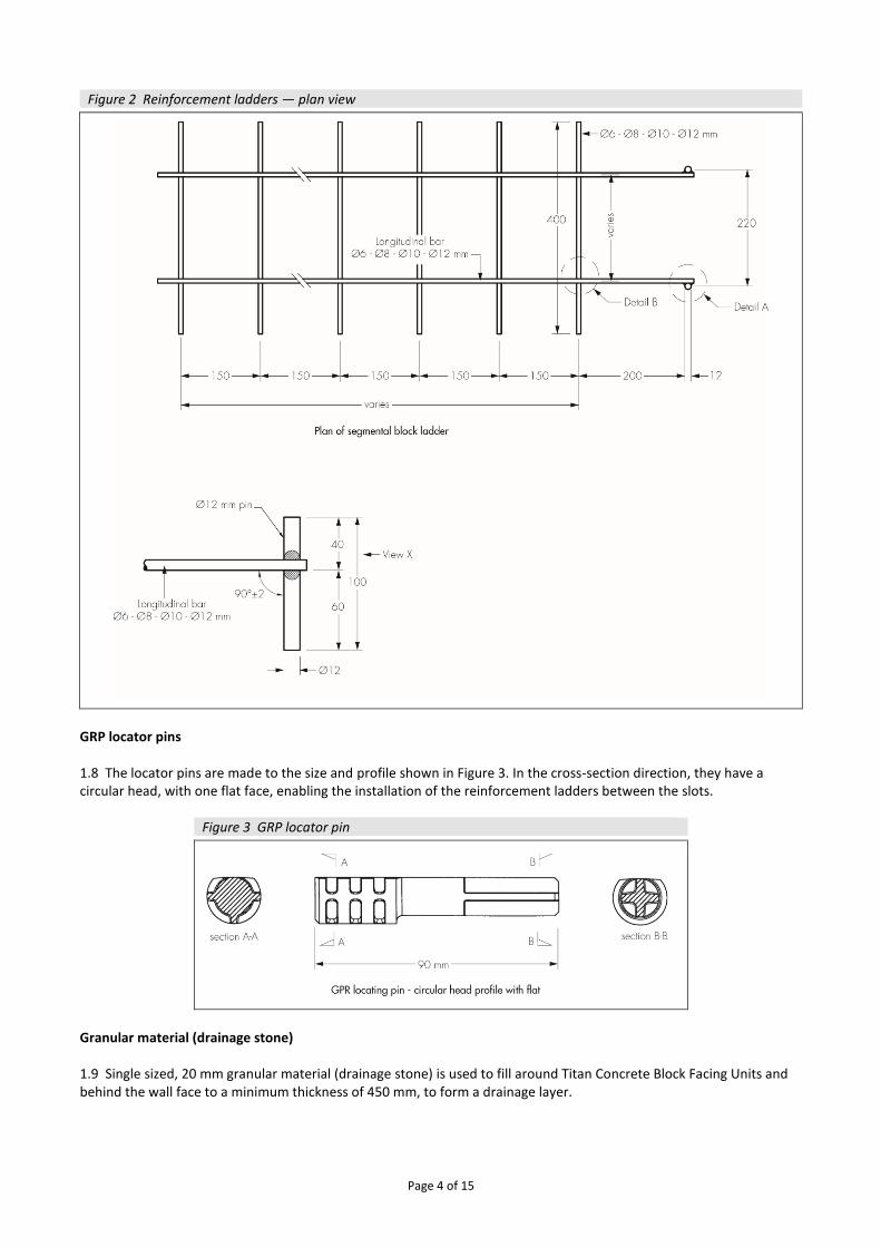
Galvanized steel reinforcement ladders 1.6 The reinforcement ladders are made from cold-reduced steel wire to BS 4482 : 2005, cut to length, welded to the configuration shown in Figure 2 and then hot-dip galvanized to BS EN ISO 1461 : 2009, with an average galvanized coating thickness of 1000 g.m-2. The reinforcement ladders are supplied in various lengths to suit specific project requirements. 1.7 The following reinforcement ladder configurations have been assessed by the BBA for use with the system, defined by longitudinal bar and cross bar diameter (prior to galvanizing): 6 x 6 mm, 6 x 8 mm, 6 x 10 mm, 6 x 12 mm, 8 x 6 mm, 8 x 8 mm, 8 x 10 mm, 8 x 12 mm, 10 x 6 mm, 10 x 8 mm, 10 x 10 mm, 10 x 12 mm, 12 x 6 mm, 12 x 8 mm, 12 x 10 mm and 12 x 12 mm . The connector pins are always 12 mm diameter. Other ladder configurations are produced by the manufacturer for use with the system, but are outside the scope of this Certificate.
Page 4 of 15
Figure 2 Reinforcement ladders — plan view
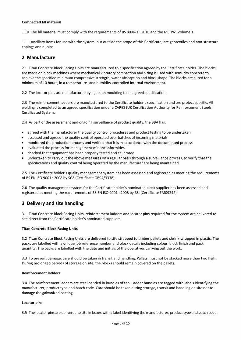
GRP locator pins 1.8 The locator pins are made to the size and profile shown in Figure 3. In the cross-section direction, they have a circular head, with one flat face, enabling the installation of the reinforcement ladders between the slots.
Figure 3 GRP locator pin
Granular material (drainage stone) 1.9 Single sized, 20 mm granular material (drainage stone) is used to fill around Titan Concrete Block Facing Units and behind the wall face to a minimum thickness of 450 mm, to form a drainage layer.
Page 5 of 15
Compacted fill material 1.10 The fill material must comply with the requirements of BS 8006-1 : 2010 and the MCHW, Volume 1. 1.11 Ancillary items for use with the system, but outside the scope of this Certificate, are geotextiles and non-structural copings and quoins.
2 Manufacture 2.1 Titan Concrete Block Facing Units are manufactured to a specification agreed by the Certificate holder. The blocks are made on block machines where mechanical vibratory compaction and sizing is used with semi-dry concrete to achieve the specified minimum compressive strength, water absorption and block shape. The blocks are cured for a minimum of 10 hours, in a temperature- and humidity-controlled internal environment. 2.2 The locator pins are manufactured by injection moulding to an agreed specification. 2.3 The reinforcement ladders are manufactured to the Certificate holder’s specification and are project specific. All welding is completed to an agreed specification under a CARES (UK Certification Authority for Reinforcement Steels) Certificated System. 2.4 As part of the assessment and ongoing surveillance of product quality, the BBA has:
• agreed with the manufacturer the quality control procedures and product testing to be undertaken
• assessed and agreed the quality control operated over batches of incoming materials
• monitored the production process and verified that it is in accordance with the documented process
• evaluated the process for management of nonconformities
• checked that equipment has been properly tested and calibrated
• undertaken to carry out the above measures on a regular basis through a surveillance process, to verify that the specifications and quality control being operated by the manufacturer are being maintained.
2.5 The Certificate holder’s quality management system has been assessed and registered as meeting the requirements of BS EN ISO 9001 : 2008 by SGS (Certificate GB94/3338). 2.6 The quality management system for the Certificate holder’s nominated block supplier has been assessed and registered as meeting the requirements of BS EN ISO 9001 : 2008 by BSI (Certificate FM09242).
3 Delivery and site handling 3.1 Titan Concrete Block Facing Units, reinforcement ladders and locator pins required for the system are delivered to site direct from the Certificate holder’s nominated suppliers. Titan Concrete Block Facing Units 3.2 Titan Concrete Block Facing Units are delivered to site strapped to timber pallets and shrink-wrapped in plastic. The packs are labelled with a unique job reference number and block details including colour, block finish and pack quantity. The packs are labelled with the date and initials of the operatives carrying out the work. 3.3 To prevent damage, care should be taken in transit and handling. Pallets must not be stacked more than two high. During prolonged periods of storage on site, the blocks should remain covered on the pallets. Reinforcement ladders 3.4 The reinforcement ladders are steel banded in bundles of ten. Ladder bundles are tagged with labels identifying the manufacturer, product type and batch code. Care should be taken during storage, transit and handling on site not to damage the galvanized coating. Locator pins 3.5 The locator pins are delivered to site in boxes with a label identifying the manufacturer, product type and batch code.
Page 6 of 15
Assessment and Technical Investigations The following is a summary of the assessment and technical investigations carried out on the Titan Wall System for reinforced soil retaining walls and bridge abutments.
Design Considerations
4 Use 4.1 The Titan Wall System for reinforced soil retaining walls and bridge abutments is satisfactory for the construction of reinforced soil retaining walls and bridge abutments up to a maximum height of 10 metres. Walls above this height require special consideration and are outside the scope of this Certificate. 4.2 Structural stability of the system is achieved through:
• frictional interaction and interlocking of the soil particles on the reinforcement ladders
• the strength of the reinforcement ladders
• the mechanical connection of the reinforcement ladder to the blocks
• interface shear resistance between the adjacent blocks and between the layers of the reinforcement.
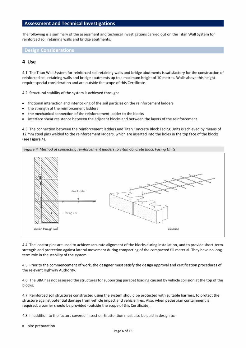
4.3 The connection between the reinforcement ladders and Titan Concrete Block Facing Units is achieved by means of 12 mm steel pins welded to the reinforcement ladders, which are inserted into the holes in the top face of the blocks (see Figure 4).
Figure 4 Method of connecting reinforcement ladders to Titan Concrete Block Facing Units
4.4 The locator pins are used to achieve accurate alignment of the blocks during installation, and to provide short-term strength and protection against lateral movement during compacting of the compacted fill material. They have no long-term role in the stability of the system. 4.5 Prior to the commencement of work, the designer must satisfy the design approval and certification procedures of the relevant Highway Authority. 4.6 The BBA has not assessed the structures for supporting parapet loading caused by vehicle collision at the top of the blocks. 4.7 Reinforced soil structures constructed using the system should be protected with suitable barriers, to protect the structure against potential damage from vehicle impact and vehicle fires. Also, when pedestrian containment is required, a barrier should be provided (outside the scope of this Certificate). 4.8 In addition to the factors covered in section 6, attention must also be paid in design to:
• site preparation
Page 7 of 15
• compacted fill material properties
• the specification for placing and compaction of the fill material
• drainage behind the wall
• protection of the reinforcement ladders against damage during installation. 4.9 It is considered that following correct design, workmanship and the recommendations of this Certificate, the line and level tolerances defined in BS 8006-1 : 2010, Table 18, for the construction of retaining walls, can be achieved.
5 Practicability of installation 5.1 The system is designed to be installed by trained contractors in accordance with the specifications and construction drawings provided by the Certificate holder and the specifications given in this Certificate (see the Installation part of this Certificate).
6 Mechanical properties Design methodology 6.1 Retaining walls and bridge abutments constructed using the system must be designed in accordance with BS 8006-1 : 2010 and the MCHW, Volume 1. 6.2 In accordance with BS 8006-1 : 2010, Annex B, the required design life for permanent walls and bridge abutments is 120 years. 6.3 To evaluate the overall stability of the system, it is necessary to consider: • the long-term strength of the reinforcement ladders to resist the project specific ultimate and serviceability design
loads • the design strength of the connection between the reinforcement ladders and the blocks • interface shear capacity of the blocks between reinforcement ladders • interaction between the soil and the reinforcement ladders (resistance to sliding and pull-out). 6.4 For all design load cases, the design load that must be resisted (Tj) is calculated as set out in BS 8006-1 : 2010, using the prescribed load factors recommended in this Standard. In each case the factored design load must be less than or equal to the factored design strength. 6.5 Design strengths, parameters and partial factors for use in the design of the system are given in sections 6.6 to 6.19. Design strength of reinforcement ladders (TD(Ladder)) 6.6 The design strength at the ultimate limit state (ULS), of the reinforcement ladders (TD(Ladder)) is calculated from the equation:
TD(Ladder) = TB(Ladder)
fm fn
where: TB(Ladder) is the un-factored strength of the ladder reinforcement (determined by calculation) fm is the material partial factor (taken as 1.50 in accordance with Annex A of BS 8006-1 : 2010) fn is the partial factor for ramification of failure, in accordance with BS 8006-1 : 2010, Table 9. 6.7 The design strength of the reinforcement ladders is governed by the long-term tensile strength of the longitudinal bars. The un-factored strength of the reinforcement ladder is therefore two times the cross-sectional area of the longitudinal bars (after reduction to allow for the long-term effects of corrosion) and the characteristic yield strength for the steel cross-bars of 460 N.mm-2. Table 4 of BS 8006-1 : 2010 specifies a sacrificial steel thickness of 0.75 mm for a 120 year service life, for galvanized steel in land based structures, giving a total reduction in diameter of 1.50 mm.
Page 8 of 15
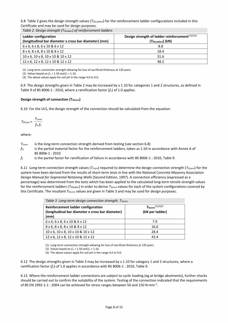
6.8 Table 2 gives the design strength values (TD(Ladder)) for the reinforcement ladder configurations included in this Certificate and may be used for design purposes.
Table 2 Design strength (TDladder) of reinforcement ladders Ladder configuration (longitudinal bar diameter x cross bar diameter) (mm)
Design strength of ladder reinforcement(1)(2)(3)
(TD(Ladder)) (kN)
6 x 6, 6 x 8, 6 x 10 & 6 x 12 8.8
8 x 6, 8 x 8, 8 x 10 & 8 x 12 18.4
10 x 6, 10 x 8, 10 x 10 & 10 x 12 31.6
12 x 6, 12 x 8, 12 x 10 & 12 x 12 48.2 (1) Long-term connection strength allowing for loss of sacrificial thickness at 120 years. (2) Values based on fm = 1.50 and fn = 1.10. (3) The above values apply for soil pH in the range 4.0 to 9.0.
6.9 The design strengths given in Table 2 may be increased by x 1.10 for categories 1 and 2 structures, as defined in Table 9 of BS 8006-1 : 2010, where a ramification factor (fn) of 1.0 applies. Design strength of connection (TDConn) 6.10 For the ULS, the design strength of the connection should be calculated from the equation:
TDConn = TConn
fm fn
where: TConn is the long-term connection strength derived from testing (see section 6.8) fm is the partial material factor for the reinforcement ladders, taken as 1.50 in accordance with Annex A of
BS 8006-1 : 2010 fn is the partial factor for ramification of failure in accordance with BS 8006-1 : 2010, Table 9.
6.11 Long-term connection strength values (TConn) required to determine the design connection strength (TDconn) for the
system have been derived from the results of short-term tests in line with the National Concrete Masonry Association Design Manual for Segmental Retaining Walls (Second Edition, 1997). A connection efficiency (expressed as a percentage) was determined from the tests which has been applied to the calculated long-term tensile strength values for the reinforcement ladders (TDladder) in order to derive TDconn values for each of the system configurations covered by this Certificate. The resultant TDconn values are given in Table 3 and may be used for design purposes.
Table 3 Long-term design connection strength, TDconn
Reinforcement ladder configuration (longitudinal bar diameter x cross bar diameter) (mm)
TDconn(1)(2)(3)
(kN per ladder)
6 x 6, 6 x 8, 6 x 10 & 6 x 12 7.9
8 x 6, 8 x 8, 8 x 10 & 8 x 12 16.6
10 x 6, 10 x 8, 10 x 10 & 10 x 12 28.4
12 x 6, 12 x 8, 12 x 10 & 12 x 12 43.4 (1) Long-term connection strength allowing for loss of sacrificial thickness at 120 years. (2) Values based on fm = 1.50 and fn = 1.10. (3) The above values apply for soil pH in the range 4.0 to 9.0.
6.12 The design strengths given in Table 3 may be increased by x 1.10 for category 1 and 2 structures, where a ramification factor (fn) of 1.0 applies in accordance with BS 8006-1 : 2010, Table 9. 6.13 Where the reinforcement ladder connections are subject to cyclic loading (eg at bridge abutments), further checks should be carried out to confirm the suitability of the system. Testing of the connection indicated that the requirements of BS EN 1992-1-1 : 2004 can be achieved for stress ranges between 50 and 150 N·mm-2.
Page 9 of 15
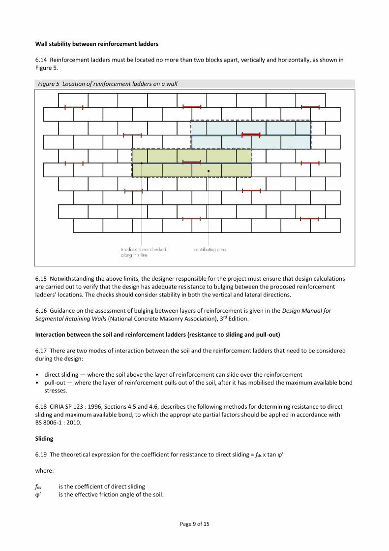
Wall stability between reinforcement ladders 6.14 Reinforcement ladders must be located no more than two blocks apart, vertically and horizontally, as shown in Figure 5. Figure 5 Location of reinforcement ladders on a wall
6.15 Notwithstanding the above limits, the designer responsible for the project must ensure that design calculations are carried out to verify that the design has adequate resistance to bulging between the proposed reinforcement ladders’ locations. The checks should consider stability in both the vertical and lateral directions. 6.16 Guidance on the assessment of bulging between layers of reinforcement is given in the Design Manual for Segmental Retaining Walls (National Concrete Masonry Association), 3rd Edition. Interaction between the soil and reinforcement ladders (resistance to sliding and pull-out) 6.17 There are two modes of interaction between the soil and the reinforcement ladders that need to be considered during the design: • direct sliding — where the soil above the layer of reinforcement can slide over the reinforcement • pull-out — where the layer of reinforcement pulls out of the soil, after it has mobilised the maximum available bond
stresses. 6.18 CIRIA SP 123 : 1996, Sections 4.5 and 4.6, describes the following methods for determining resistance to direct sliding and maximum available bond, to which the appropriate partial factors should be applied in accordance with BS 8006-1 : 2010. Sliding 6.19 The theoretical expression for the coefficient for resistance to direct sliding = fds x tan ϕ’ where: fds is the coefficient of direct sliding ϕ’ is the effective friction angle of the soil.
Page 10 of 15
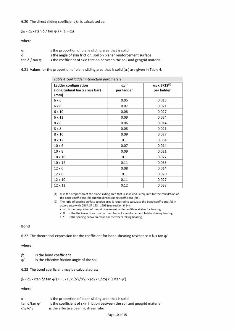
6.20 The direct sliding coefficient fds is calculated as: fds = αs x (tan δ / tan ϕ’) + (1 – αs) where: αs is the proportion of plane sliding area that is solid δ is the angle of skin friction, soil on planar reinforcement surface tan δ / tan ϕ’ is the coefficient of skin friction between the soil and geogrid material. 6.21 Values for the proportion of plane sliding area that is solid (αs) are given in Table 4.
Table 4 Soil ladder interaction parameters Ladder configuration
(longitudinal bar x cross bar) (mm)
αs(1)
per ladder αb x B/2S(2)
per ladder
6 x 6 0.05 0.015
6 x 8 0.07 0.021
6 x 10 0.08 0.027
6 x 12 0.09 0.034
8 x 6 0.06 0.014
8 x 8 0.08 0.021
8 x 10 0.09 0.027
8 x 12 0.1 0.034
10 x 6 0.07 0.014
10 x 8 0.09 0.021
10 x 10 0.1 0.027
10 x 12 0.11 0.033
12 x 6 0.08 0.014
12 x 8 0.1 0.020
12 x 10 0.11 0.027
12 x 12 0.12 0.033 (1) αs is the proportion of the plane sliding area that is solid and is required for the calculation of
the bond coefficient (fb) and the direct sliding coefficient (fds). (2) The ratio of bearing surface to plan area is required to calculate the bond coefficient (fb) in
accordance with CIRIA SP 123 : 1996 (see section 6.14): • αb is the proportion of the reinforcement ladder width available for bearing • B is the thickness of a cross bar members of a reinforcement ladders taking bearing • S is the spacing between cross bar members taking bearing.
Bond 6.22 The theoretical expression for the coefficient for bond shearing resistance = fb x tan ϕ’ where: fb is the bond coefficient ϕ’ is the effective friction angle of the soil. 6.23 The bond coefficient may be calculated as: fb = αs x (tan δ/ tan ϕ’) + F1 x F2 x (ơ’b/ơ’n) x (αb x B/2S) x (1/tan ϕ’) where:
αs is the proportion of plane sliding area that is solid tan δ/tan ϕ’ is the coefficient of skin friction between the soil and geogrid material ơ’b /ơ’n is the effective bearing stress ratio
Page 11 of 15
αb x B/2S is the ratio of bearing surface to plan area ϕ’ is the angle of shearing resistance in terms of effective stress δ is the angle of skin friction, soil on planar reinforcement surface ơ’b is the effective bearing stress on the reinforcement ơ’n is the normal effective stress F1 is a factor to allow for scale effects and may be calculated from the formula F1 = (20 – B/D50)/10,
where D50 is the mean particle size of the compacted fill material F2 is the shape factor, which may be taken as 1.0 for circular cross bar bars. 6.24 For initial design purposes the coefficient of skin friction (tan δ/tan ϕ’) for the reinforcement ladders when buried in compacted fill may be conservatively assumed to be 0.6. Values for the ratio of bearing surface to plan area (αb x B/2S) are given in Table 4. Typical values for the bearing stress ratio (ơ’b/ơ’n) are given in CIRIA SP 123 : 1996, Table 4.1. 6.25 Site-specific pull-out tests should be carried out to confirm the value of bond coefficient (fb) used in the final design. Specification of compacted fill 6.26 The designer should specify the properties of the compacted fill to be used for the project and on which the design has been based. The compacted fill should meet the requirements of BS 8006-1 : 2010 and the MCHW, Volume 1, Series 600.
7 Maintenance 7.1 The exposed faces of Titan Concrete Block Facing Units may require occasional maintenance to remove dirt build up, mould and moss growth. All other components of the system are confined within the compacted fill and do not require maintenance.
8 Durability 8.1 When designed and installed in accordance with this Certificate, the system will have adequate durability for the required 120 year design life of a retaining wall and bridge abutment in the conditions encountered in the UK. 8.2 Where the blocks are to be embedded in potentially aggressive soils, the guidance given in BS 8500-1 : 2006 and BRE Special Digest 1 : 2005 should be followed.
9 Reuse and recyclability 9.1 Titan Concrete Block Facing Units can be crushed and re-used as aggregate. The compacted fill can also be re-used. The steel used for the manufacture of the reinforcement ladders may be recycled.
Installation
10 General 10.1 The installation of the Titan Wall System for reinforced soil retaining walls and bridge abutments should comply with the requirements of BS 8006-1 : 2010 and BS EN 14475 : 2006. 10.2 Detailed information on installation of the system is included in the Certificate holder’s installation instructions.
11 Procedure 11.1 Formation levels are prepared and a suitable concrete foundation, normally 600 mm wide by 150 mm deep mass concrete mix C20/25 is laid to the correct level for the first course of Titan Concrete Block Facing Units (foundation design is outside the scope of this Certificate). 11.2 Once the foundation has cured a base course of blocks can be laid and bedded on a 3:1 sand/cement mortar. The blocks are spaced using the spacing tool, with small gaps in the vertical joints. The top of each block is brushed clean
Page 12 of 15
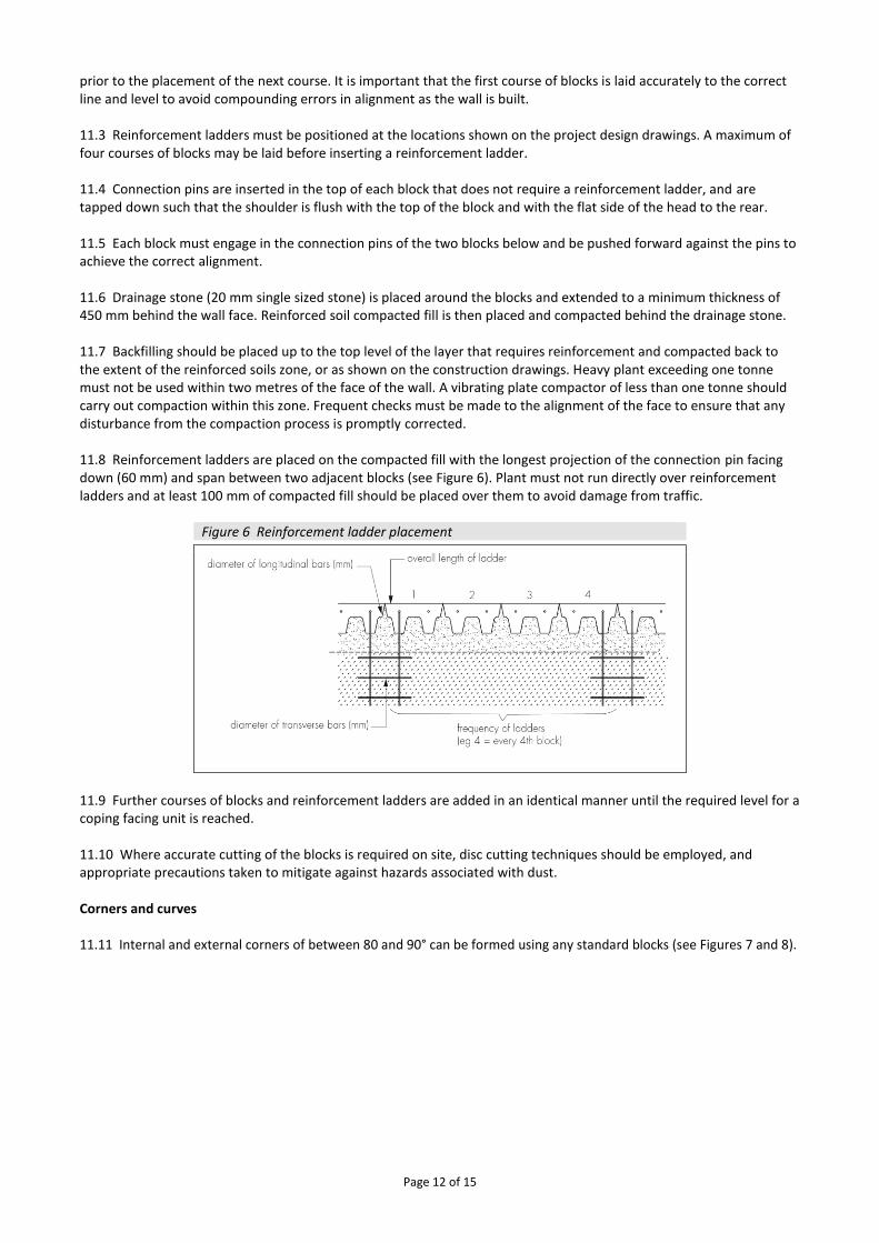
prior to the placement of the next course. It is important that the first course of blocks is laid accurately to the correct line and level to avoid compounding errors in alignment as the wall is built. 11.3 Reinforcement ladders must be positioned at the locations shown on the project design drawings. A maximum of four courses of blocks may be laid before inserting a reinforcement ladder. 11.4 Connection pins are inserted in the top of each block that does not require a reinforcement ladder, and are tapped down such that the shoulder is flush with the top of the block and with the flat side of the head to the rear. 11.5 Each block must engage in the connection pins of the two blocks below and be pushed forward against the pins to achieve the correct alignment. 11.6 Drainage stone (20 mm single sized stone) is placed around the blocks and extended to a minimum thickness of 450 mm behind the wall face. Reinforced soil compacted fill is then placed and compacted behind the drainage stone. 11.7 Backfilling should be placed up to the top level of the layer that requires reinforcement and compacted back to the extent of the reinforced soils zone, or as shown on the construction drawings. Heavy plant exceeding one tonne must not be used within two metres of the face of the wall. A vibrating plate compactor of less than one tonne should carry out compaction within this zone. Frequent checks must be made to the alignment of the face to ensure that any disturbance from the compaction process is promptly corrected. 11.8 Reinforcement ladders are placed on the compacted fill with the longest projection of the connection pin facing down (60 mm) and span between two adjacent blocks (see Figure 6). Plant must not run directly over reinforcement ladders and at least 100 mm of compacted fill should be placed over them to avoid damage from traffic.
Figure 6 Reinforcement ladder placement
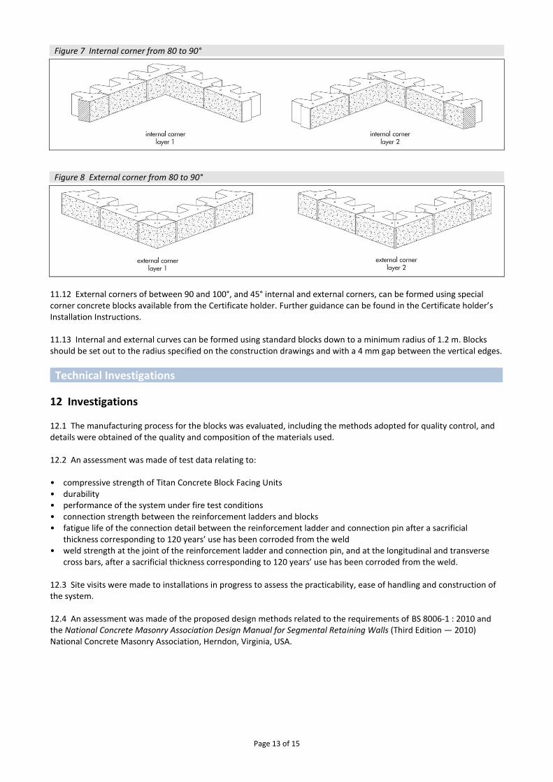
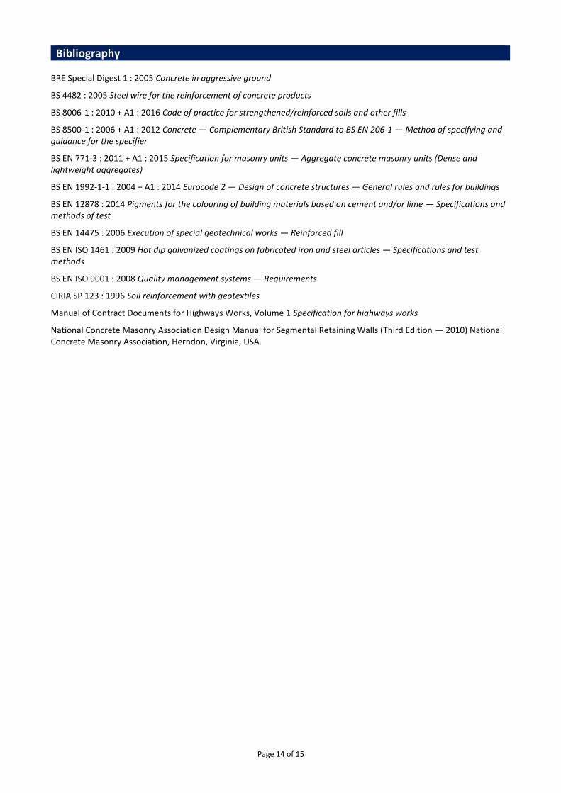
11.9 Further courses of blocks and reinforcement ladders are added in an identical manner until the required level for a coping facing unit is reached. 11.10 Where accurate cutting of the blocks is required on site, disc cutting techniques should be employed, and appropriate precautions taken to mitigate against hazards associated with dust. Corners and curves 11.11 Internal and external corners of between 80 and 90° can be formed using any standard blocks (see Figures 7 and 8).
Page 13 of 15
Figure 7 Internal corner from 80 to 90°
Figure 8 External corner from 80 to 90°
11.12 External corners of between 90 and 100°, and 45° internal and external corners, can be formed using special corner concrete blocks available from the Certificate holder. Further guidance can be found in the Certificate holder’s Installation Instructions. 11.13 Internal and external curves can be formed using standard blocks down to a minimum radius of 1.2 m. Blocks should be set out to the radius specified on the construction drawings and with a 4 mm gap between the vertical edges.
Technical Investigations
12 Investigations 12.1 The manufacturing process for the blocks was evaluated, including the methods adopted for quality control, and details were obtained of the quality and composition of the materials used. 12.2 An assessment was made of test data relating to: • compressive strength of Titan Concrete Block Facing Units • durability • performance of the system under fire test conditions • connection strength between the reinforcement ladders and blocks • fatigue life of the connection detail between the reinforcement ladder and connection pin after a sacrificial
thickness corresponding to 120 years’ use has been corroded from the weld • weld strength at the joint of the reinforcement ladder and connection pin, and at the longitudinal and transverse
cross bars, after a sacrificial thickness corresponding to 120 years’ use has been corroded from the weld. 12.3 Site visits were made to installations in progress to assess the practicability, ease of handling and construction of the system. 12.4 An assessment was made of the proposed design methods related to the requirements of BS 8006-1 : 2010 and the National Concrete Masonry Association Design Manual for Segmental Retaining Walls (Third Edition — 2010) National Concrete Masonry Association, Herndon, Virginia, USA.
Page 14 of 15
Bibliography BRE Special Digest 1 : 2005 Concrete in aggressive ground
BS 4482 : 2005 Steel wire for the reinforcement of concrete products
BS 8006-1 : 2010 + A1 : 2016 Code of practice for strengthened/reinforced soils and other fills
BS 8500-1 : 2006 + A1 : 2012 Concrete — Complementary British Standard to BS EN 206-1 — Method of specifying and guidance for the specifier
BS EN 771-3 : 2011 + A1 : 2015 Specification for masonry units — Aggregate concrete masonry units (Dense and lightweight aggregates)
BS EN 1992-1-1 : 2004 + A1 : 2014 Eurocode 2 — Design of concrete structures — General rules and rules for buildings
BS EN 12878 : 2014 Pigments for the colouring of building materials based on cement and/or lime — Specifications and methods of test
BS EN 14475 : 2006 Execution of special geotechnical works — Reinforced fill
BS EN ISO 1461 : 2009 Hot dip galvanized coatings on fabricated iron and steel articles — Specifications and test methods
BS EN ISO 9001 : 2008 Quality management systems — Requirements
CIRIA SP 123 : 1996 Soil reinforcement with geotextiles
Manual of Contract Documents for Highways Works, Volume 1 Specification for highways works
National Concrete Masonry Association Design Manual for Segmental Retaining Walls (Third Edition — 2010) National Concrete Masonry Association, Herndon, Virginia, USA.
Page 15 of 15
Conditions of Certification
13 Conditions 13.1 This Certificate:
• relates only to the product/system that is named and described on the front page
• is issued only to the company, firm, organisation or person named on the front page – no other company, firm, organisation or person may hold claim that this Certificate has been issued to them
• is valid only within the UK
• has to be read, considered and used as a whole document – it may be misleading and will be incomplete to be selective
• is copyright of the BBA
• is subject to English Law. 13.2 Publications, documents, specifications, legislation, regulations, standards and the like referenced in this Certificate are those that were current and/or deemed relevant by the BBA at the date of issue or reissue of this Certificate. 13.3 This Certificate will remain valid for an unlimited period provided that the product/system and its manufacture and/or fabrication, including all related and relevant parts and processes thereof:
• are maintained at or above the levels which have been assessed and found to be satisfactory by the BBA
• continue to be checked as and when deemed appropriate by the BBA under arrangements that it will determine
• are reviewed by the BBA as and when it considers appropriate. 13.4 The BBA has used due skill, care and diligence in preparing this Certificate, but no warranty is provided. 13.5 In issuing this Certificate the BBA is not responsible and is excluded from any liability to any company, firm, organisation or person, for any matters arising directly or indirectly from:
• the presence or absence of any patent, intellectual property or similar rights subsisting in the product/system or any other product/system
• the right of the Certificate holder to manufacture, supply, install, maintain or market the product/system
• actual installations of the product/system, including their nature, design, methods, performance, workmanship and maintenance
• any works and constructions in which the product/system is installed, including their nature, design, methods, performance, workmanship and maintenance
• any loss or damage, including personal injury, howsoever caused by the product/system, including its manufacture, supply, installation, use, maintenance and removal
• any claims by the manufacturer relating to CE marking. 13.6 Any information relating to the manufacture, supply, installation, use, maintenance and removal of this product/system which is contained or referred to in this Certificate is the minimum required to be met when the product/system is manufactured, supplied, installed, used, maintained and removed. It does not purport in any way to restate the requirements of the Health and Safety at Work etc. Act 1974, or of any other statutory, common law or other duty which may exist at the date of issue or reissue of this Certificate; nor is conformity with such information to be taken as satisfying the requirements of the 1974 Act or of any statutory, common law or other duty of care.
British Board of Agrément Bucknalls Lane Watford Herts WD25 9BA
©2018
tel: 01923 665300
[email protected] www.bbacerts.co.uk