Embed Size (px)
Citation preview
NASA GNSS Space Service Volume Update
WG-B—Enhancement of GNSS Performance, New
Services & Capabilities Joel Parker, NASA Goddard Space Flight Center
ICG-11, Sochi, Russian Federation, November 9, 2016
Keeping the universe connected.
1
Benefits of GPS/GNSS to NASA
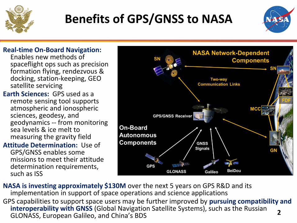
Real-time On-Board Navigation: Enables new methods of spaceflight ops such as precision formation flying, rendezvous & docking, station-keeping, GEO satellite servicing
Earth Sciences: GPS used as a remote sensing tool supports atmospheric and ionospheric sciences, geodesy, and geodynamics -- from monitoring sea levels & ice melt to measuring the gravity field
Attitude Determination: Use of GPS/GNSS enables some missions to meet their attitude determination requirements, such as ISS
NASA is investing approximately $130M over the next 5 years on GPS R&D and its implementation in support of space operations and science applications
GPS capabilities to support space users may be further improved by pursuing compatibility and interoperability with GNSS (Global Navigation Satellite Systems), such as the Russian GLONASS, European Galileo, and China’s BDS 2
3
GPS SSV Specification
Status Update
4
GPS SSV Status and Lessons Learned:
Executive Summary
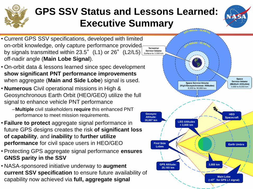
• Current GPS SSV specifications, developed with limited
on-orbit knowledge, only capture performance provided
by signals transmitted within 23.5°(L1) or 26°(L2/L5)
off-nadir angle (Main Lobe Signal).
• On-orbit data & lessons learned since spec development
show significant PNT performance improvements
when aggregate (Main and Side Lobe) signal is used.
• Numerous Civil operational missions in High &
Geosynchronous Earth Orbit (HEO/GEO) utilize the full
signal to enhance vehicle PNT performance
–Multiple civil stakeholders require this enhanced PNT
performance to meet mission requirements.
• Failure to protect aggregate signal performance in
future GPS designs creates the risk of significant loss
of capability, and inability to further utilize
performance for civil space users in HEO/GEO
• Protecting GPS aggregate signal performance ensures
GNSS parity in the SSV
• NASA-sponsored initiative underway to augment
current SSV specification to ensure future availability of
capability now achieved via full, aggregate signal
5
Progress Since November 2015 ICG Meeting, Boulder, Colorado, USA
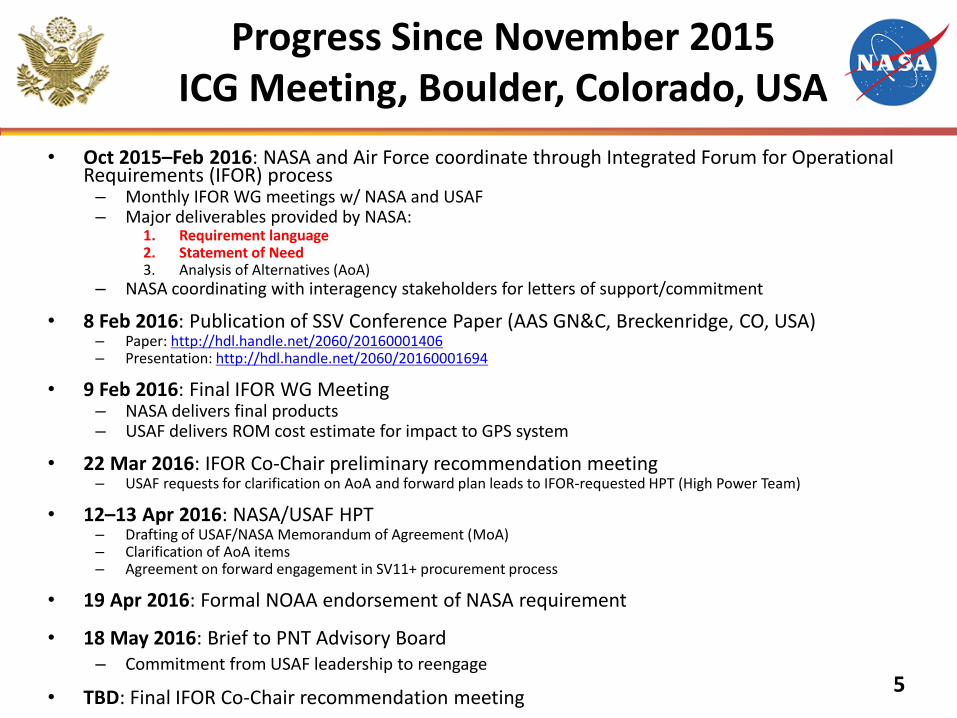
• Oct 2015–Feb 2016: NASA and Air Force coordinate through Integrated Forum for Operational Requirements (IFOR) process
– Monthly IFOR WG meetings w/ NASA and USAF – Major deliverables provided by NASA:
1. Requirement language 2. Statement of Need 3. Analysis of Alternatives (AoA)
– NASA coordinating with interagency stakeholders for letters of support/commitment
• 8 Feb 2016: Publication of SSV Conference Paper (AAS GN&C, Breckenridge, CO, USA) – Paper: http://hdl.handle.net/2060/20160001406 – Presentation: http://hdl.handle.net/2060/20160001694
• 9 Feb 2016: Final IFOR WG Meeting – NASA delivers final products – USAF delivers ROM cost estimate for impact to GPS system
• 22 Mar 2016: IFOR Co-Chair preliminary recommendation meeting – USAF requests for clarification on AoA and forward plan leads to IFOR-requested HPT (High Power Team)
• 12–13 Apr 2016: NASA/USAF HPT – Drafting of USAF/NASA Memorandum of Agreement (MoA) – Clarification of AoA items – Agreement on forward engagement in SV11+ procurement process
• 19 Apr 2016: Formal NOAA endorsement of NASA requirement
• 18 May 2016: Brief to PNT Advisory Board – Commitment from USAF leadership to reengage
• TBD: Final IFOR Co-Chair recommendation meeting
6
Key Civil Stakeholder: GOES-R
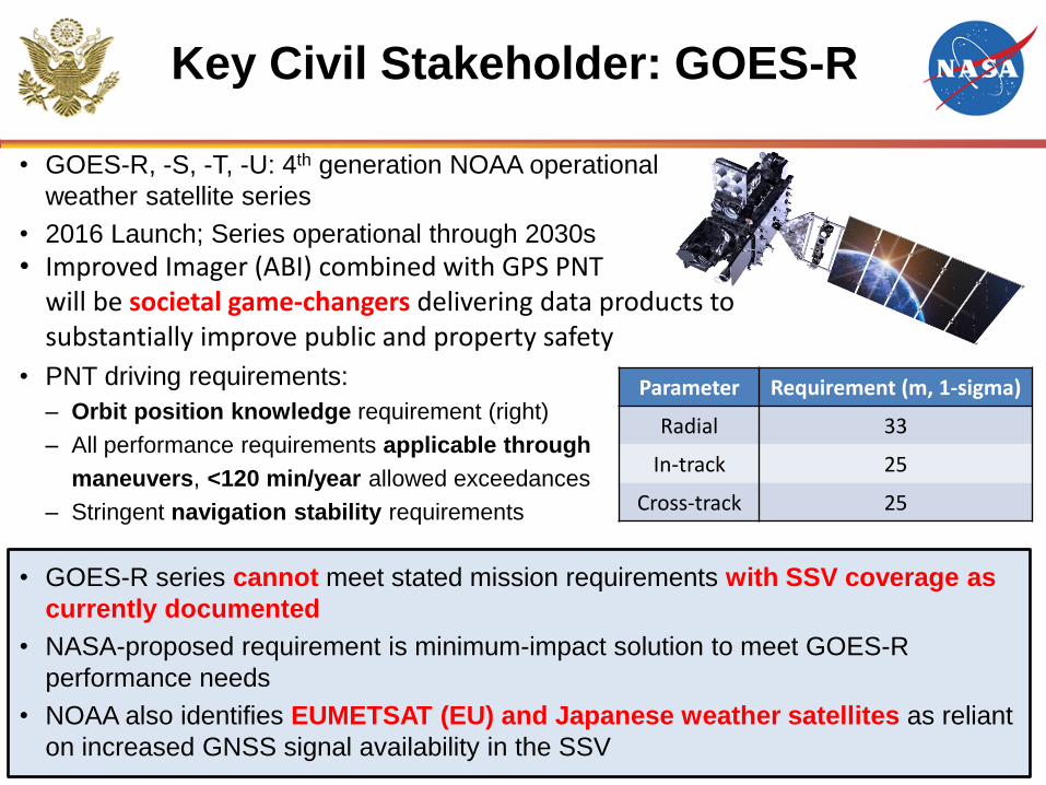
• GOES-R, -S, -T, -U: 4th generation NOAA operational
weather satellite series
• 2016 Launch; Series operational through 2030s
• Improved Imager (ABI) combined with GPS PNT will be societal game-changers delivering data products to substantially improve public and property safety
• PNT driving requirements:
– Orbit position knowledge requirement (right)
– All performance requirements applicable through
maneuvers, <120 min/year allowed exceedances
– Stringent navigation stability requirements
• GOES-R series cannot meet stated mission requirements with SSV coverage as
currently documented
• NASA-proposed requirement is minimum-impact solution to meet GOES-R
performance needs
• NOAA also identifies EUMETSAT (EU) and Japanese weather satellites as reliant
on increased GNSS signal availability in the SSV
Parameter Requirement (m, 1-sigma)
Radial 33
In-track 25
Cross-track 25
7
NASA Proposed SSV
Requirement Language (in-work)
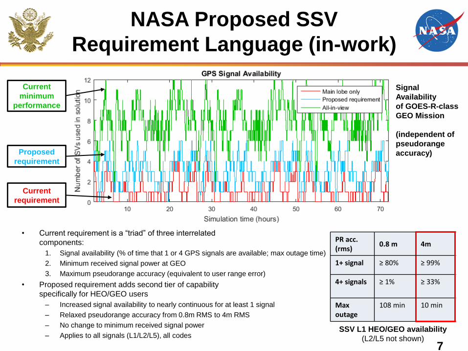
• Current requirement is a “triad” of three interrelated
components:
1. Signal availability (% of time that 1 or 4 GPS signals are available; max outage time)
2. Minimum received signal power at GEO
3. Maximum pseudorange accuracy (equivalent to user range error)
• Proposed requirement adds second tier of capability
specifically for HEO/GEO users
– Increased signal availability to nearly continuous for at least 1 signal
– Relaxed pseudorange accuracy from 0.8m RMS to 4m RMS
– No change to minimum received signal power
– Applies to all signals (L1/L2/L5), all codes
Proposed
requirement
Current
requirement
Current
minimum
performance
PR acc. (rms)
0.8 m 4m
1+ signal ≥ 80% ≥ 99%
4+ signals ≥ 1% ≥ 33%
Max outage
108 min 10 min
SSV L1 HEO/GEO availability
(L2/L5 not shown)
Signal
Availability
of GOES-R-class
GEO Mission
(independent of
pseudorange
accuracy)
8
NASA SSV User Segment
Status Update
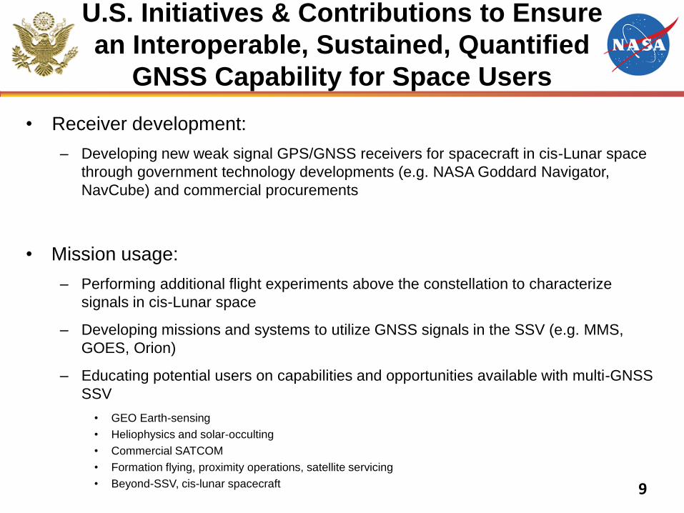
U.S. Initiatives & Contributions to Ensure
an Interoperable, Sustained, Quantified
GNSS Capability for Space Users
• Receiver development:
– Developing new weak signal GPS/GNSS receivers for spacecraft in cis-Lunar space
through government technology developments (e.g. NASA Goddard Navigator,
NavCube) and commercial procurements
• Mission usage:
– Performing additional flight experiments above the constellation to characterize
signals in cis-Lunar space
– Developing missions and systems to utilize GNSS signals in the SSV (e.g. MMS,
GOES, Orion)
– Educating potential users on capabilities and opportunities available with multi-GNSS
SSV
• GEO Earth-sensing
• Heliophysics and solar-occulting
• Commercial SATCOM
• Formation flying, proximity operations, satellite servicing
• Beyond-SSV, cis-lunar spacecraft 9
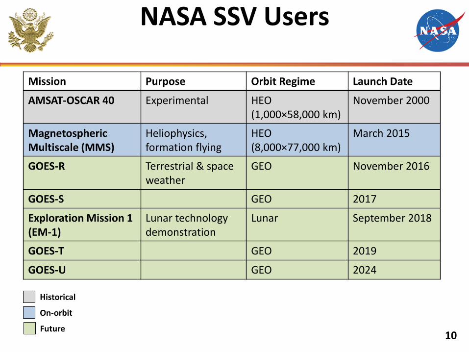
NASA SSV Users
10
Mission Purpose Orbit Regime Launch Date
AMSAT-OSCAR 40 Experimental HEO (1,000×58,000 km)
November 2000
Magnetospheric Multiscale (MMS)
Heliophysics, formation flying
HEO (8,000×77,000 km)
March 2015
GOES-R Terrestrial & space weather
GEO November 2016
GOES-S GEO 2017
Exploration Mission 1 (EM-1)
Lunar technology demonstration
Lunar September 2018
GOES-T GEO 2019
GOES-U GEO 2024
Historical
On-orbit
Future
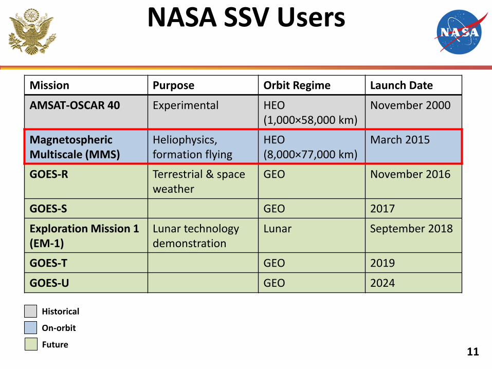
NASA SSV Users
11
Mission Purpose Orbit Regime Launch Date
AMSAT-OSCAR 40 Experimental HEO (1,000×58,000 km)
November 2000
Magnetospheric Multiscale (MMS)
Heliophysics, formation flying
HEO (8,000×77,000 km)
March 2015
GOES-R Terrestrial & space weather
GEO November 2016
GOES-S GEO 2017
Exploration Mission 1 (EM-1)
Lunar technology demonstration
Lunar September 2018
GOES-T GEO 2019
GOES-U GEO 2024
Historical
On-orbit
Future
12
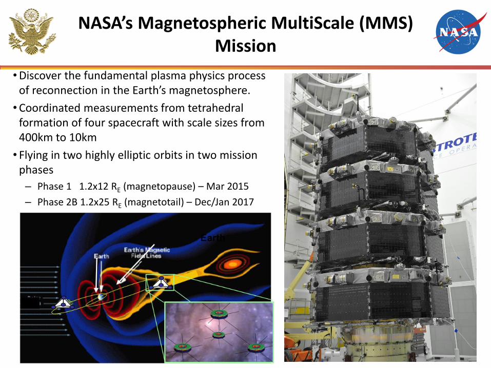
NASA’s Magnetospheric MultiScale (MMS) Mission
• Discover the fundamental plasma physics process of reconnection in the Earth’s magnetosphere.
• Coordinated measurements from tetrahedral formation of four spacecraft with scale sizes from 400km to 10km
• Flying in two highly elliptic orbits in two mission phases
– Phase 1 1.2x12 RE (magnetopause) – Mar 2015
– Phase 2B 1.2x25 RE (magnetotail) – Dec/Jan 2017
13
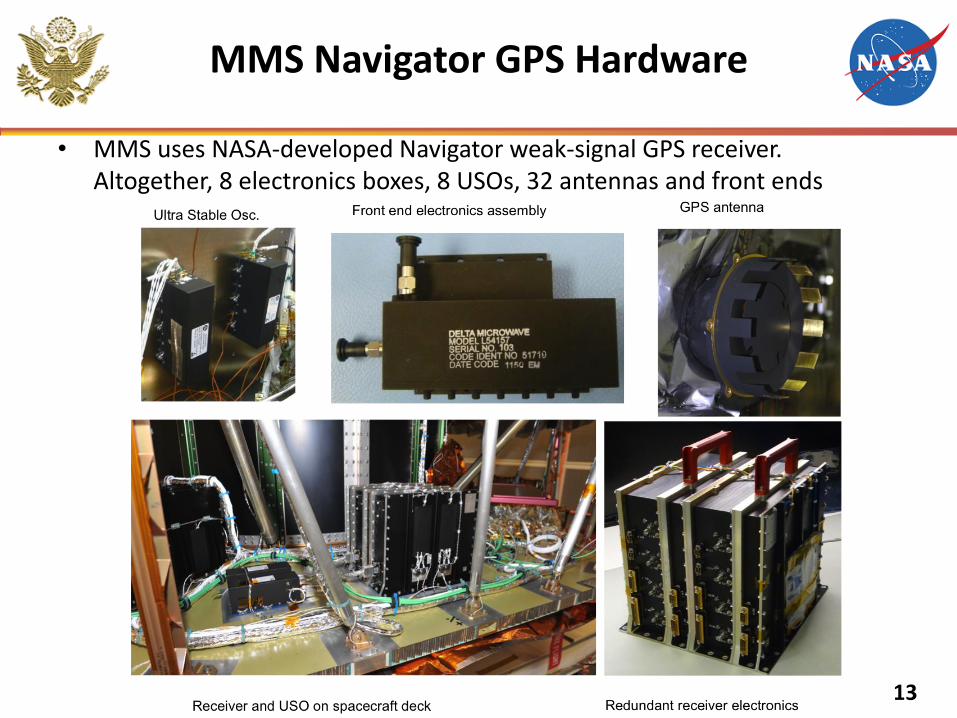
MMS Navigator GPS Hardware
• MMS uses NASA-developed Navigator weak-signal GPS receiver. Altogether, 8 electronics boxes, 8 USOs, 32 antennas and front ends
14
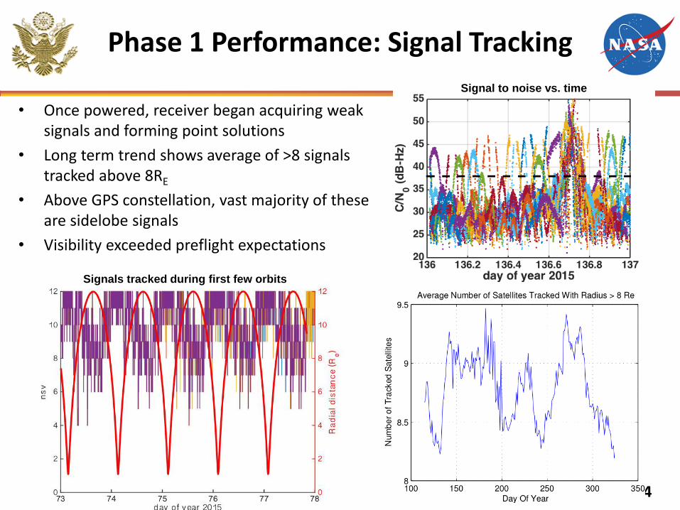
• Once powered, receiver began acquiring weak signals and forming point solutions
• Long term trend shows average of >8 signals tracked above 8RE
• Above GPS constellation, vast majority of these are sidelobe signals
• Visibility exceeded preflight expectations
Signals tracked during first few orbits
Signal to noise vs. time
Phase 1 Performance: Signal Tracking
15
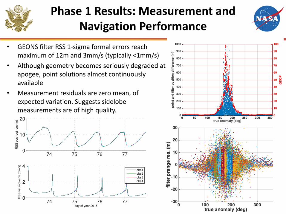
Phase 1 Results: Measurement and Navigation Performance
• GEONS filter RSS 1-sigma formal errors reach maximum of 12m and 3mm/s (typically <1mm/s)
• Although geometry becomes seriously degraded at apogee, point solutions almost continuously available
• Measurement residuals are zero mean, of expected variation. Suggests sidelobe measurements are of high quality.
Maneuver
16
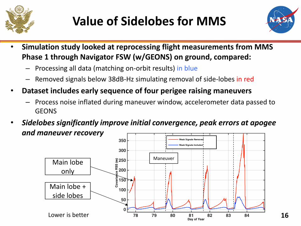
• Simulation study looked at reprocessing flight measurements from MMS Phase 1 through Navigator FSW (w/GEONS) on ground, compared:
– Processing all data (matching on-orbit results) in blue
– Removed signals below 38dB-Hz simulating removal of side-lobes in red
• Dataset includes early sequence of four perigee raising maneuvers
– Process noise inflated during maneuver window, accelerometer data passed to GEONS
• Sidelobes significantly improve initial convergence, peak errors at apogee and maneuver recovery
Value of Sidelobes for MMS
Main lobe only
Main lobe + side lobes
Lower is better
17
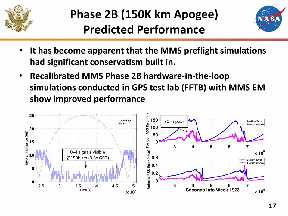
Phase 2B (150K km Apogee) Predicted Performance
• It has become apparent that the MMS preflight simulations had significant conservatism built in.
• Recalibrated MMS Phase 2B hardware-in-the-loop simulations conducted in GPS test lab (FFTB) with MMS EM show improved performance
2.5 3 3.5 4 4.5 5
x 105
0
5
10
15
20
25
NS
VS
an
d D
ista
nc
e (
RE
)
Time (s)
Tracked Svs
Radius
0–4 signals visible @150k km (3.5x GEO)
80 m peak
18
Interoperable GNSS SSV
Status and Recommendations
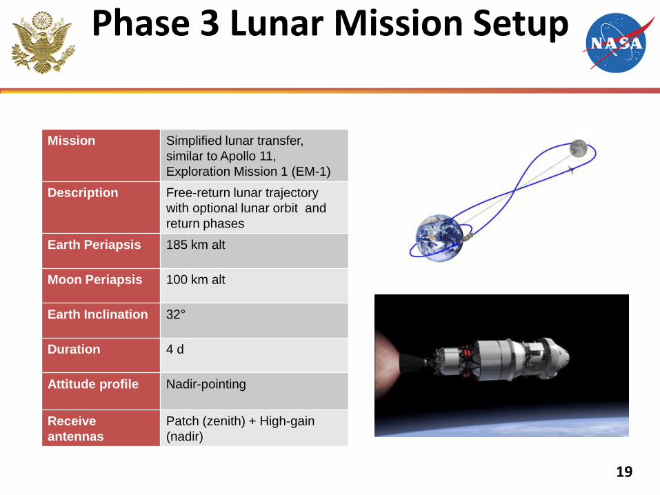
Phase 3 Lunar Mission Setup
Mission Simplified lunar transfer,
similar to Apollo 11,
Exploration Mission 1 (EM-1)
Description Free-return lunar trajectory
with optional lunar orbit and
return phases
Earth Periapsis 185 km alt
Moon Periapsis 100 km alt
Earth Inclination 32°
Duration 4 d
Attitude profile Nadir-pointing
Receive
antennas
Patch (zenith) + High-gain
(nadir)
19
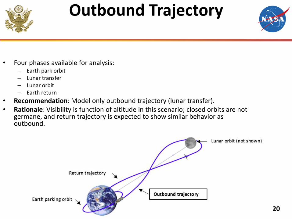
Outbound Trajectory
• Four phases available for analysis: – Earth park orbit – Lunar transfer – Lunar orbit – Earth return
• Recommendation: Model only outbound trajectory (lunar transfer). • Rationale: Visibility is function of altitude in this scenario; closed orbits are not
germane, and return trajectory is expected to show similar behavior as outbound.
20
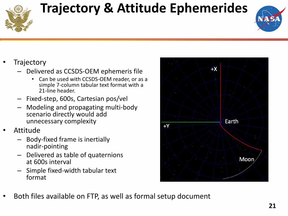
Trajectory & Attitude Ephemerides
• Trajectory – Delivered as CCSDS-OEM ephemeris file
• Can be used with CCSDS-OEM reader, or as a simple 7-column tabular text format with a 21-line header.
– Fixed-step, 600s, Cartesian pos/vel – Modeling and propagating multi-body
scenario directly would add unnecessary complexity
• Attitude – Body-fixed frame is inertially
nadir-pointing – Delivered as table of quaternions
at 600s interval – Simple fixed-width tabular text
format
• Both files available on FTP, as well as formal setup document
21
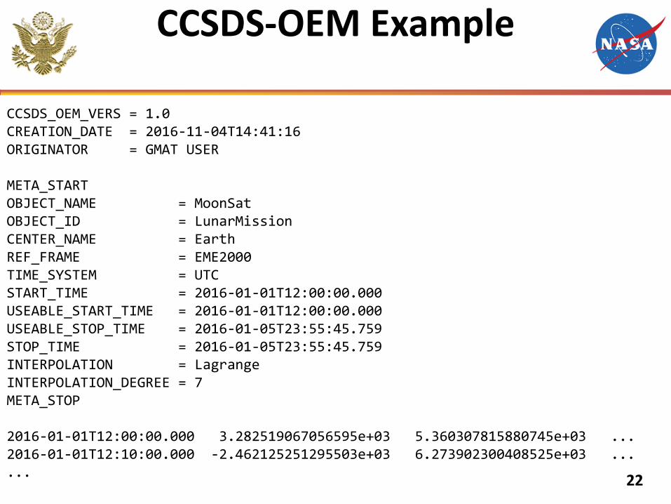
CCSDS-OEM Example
CCSDS_OEM_VERS = 1.0 CREATION_DATE = 2016-11-04T14:41:16 ORIGINATOR = GMAT USER META_START OBJECT_NAME = MoonSat OBJECT_ID = LunarMission CENTER_NAME = Earth REF_FRAME = EME2000 TIME_SYSTEM = UTC START_TIME = 2016-01-01T12:00:00.000 USEABLE_START_TIME = 2016-01-01T12:00:00.000 USEABLE_STOP_TIME = 2016-01-05T23:55:45.759 STOP_TIME = 2016-01-05T23:55:45.759 INTERPOLATION = Lagrange INTERPOLATION_DEGREE = 7 META_STOP 2016-01-01T12:00:00.000 3.282519067056595e+03 5.360307815880745e+03 ... 2016-01-01T12:10:00.000 -2.462125251295503e+03 6.273902300408525e+03 ... ...
22
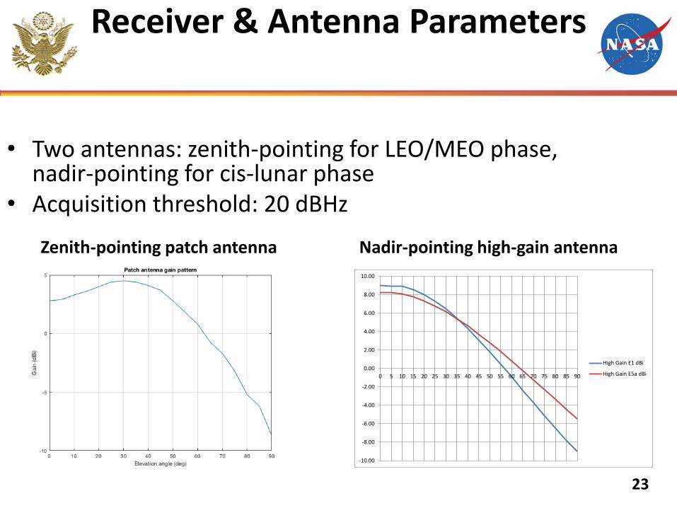
Receiver & Antenna Parameters
• Two antennas: zenith-pointing for LEO/MEO phase, nadir-pointing for cis-lunar phase
• Acquisition threshold: 20 dBHz
Nadir-pointing high-gain antenna
-10.00
-8.00
-6.00
-4.00
-2.00
0.00
2.00
4.00
6.00
8.00
10.00
0 5 10 15 20 25 30 35 40 45 50 55 60 65 70 75 80 85 90
High Gain E1 dBi
High Gain E5a dBi
Zenith-pointing patch antenna
23
ICG WG-B Observations
• WG-B is making significant progress in establishing an interoperable Global
Navigation Satellite System (GNSS) Space Service Volume (SSV) through pre-
work, analyses and regularly held teleconferences.
• Co-chair leadership has kept the WG-B team at a high momentum.
• WG-B Analyses underway to solidify understanding of expected HEO/GEO user
performance using all provider’s SSV signals (BDS, Galileo, GLONASS, GPS,
IRNSS, QZSS).
• NASA encourages all providers to support, and continue to support, WG-B
initiatives, particularly the current analysis effort. We will go far, if everyone
participates.
• Recent ICG WG-B initiatives have led some providers (e.g. EU) to perform
government studies to investigate best approaches for development and
specification of SSV within their constellations. This should be encouraged and
expanded to all providers.
• WG-B is “home” to critical development, specification, and outreach of the SSV, a
truly revolutionary concept that is just beginning to be realized. 24
ICG SSV Outreach Activities
25
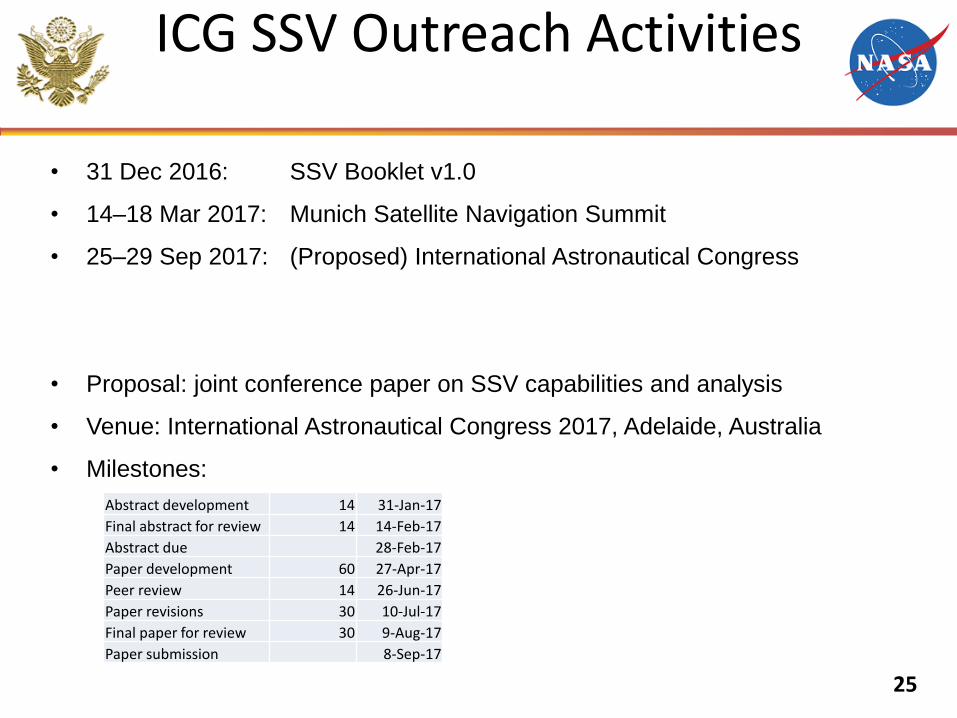
• 31 Dec 2016: SSV Booklet v1.0
• 14–18 Mar 2017: Munich Satellite Navigation Summit
• 25–29 Sep 2017: (Proposed) International Astronautical Congress
• Proposal: joint conference paper on SSV capabilities and analysis
• Venue: International Astronautical Congress 2017, Adelaide, Australia
• Milestones:
Abstract development 14 31-Jan-17
Final abstract for review 14 14-Feb-17
Abstract due 28-Feb-17
Paper development 60 27-Apr-17
Peer review 14 26-Jun-17
Paper revisions 30 10-Jul-17
Final paper for review 30 9-Aug-17
Paper submission 8-Sep-17
US Team Recommendations to
GNSS Providers
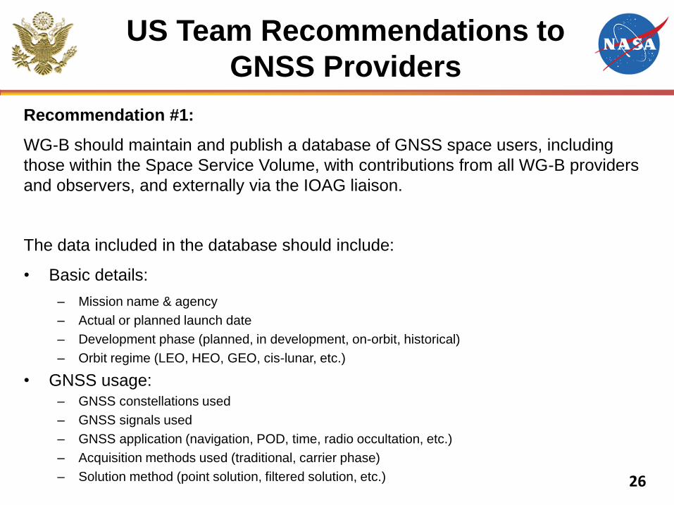
Recommendation #1:
WG-B should maintain and publish a database of GNSS space users, including
those within the Space Service Volume, with contributions from all WG-B providers
and observers, and externally via the IOAG liaison.
The data included in the database should include:
• Basic details:
– Mission name & agency
– Actual or planned launch date
– Development phase (planned, in development, on-orbit, historical)
– Orbit regime (LEO, HEO, GEO, cis-lunar, etc.)
• GNSS usage: – GNSS constellations used
– GNSS signals used
– GNSS application (navigation, POD, time, radio occultation, etc.)
– Acquisition methods used (traditional, carrier phase)
– Solution method (point solution, filtered solution, etc.)
26
Example: IOAG GNSS Missions Reference Tables
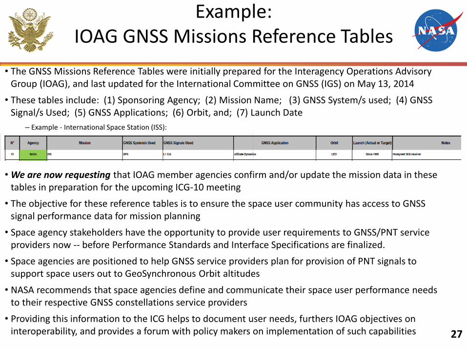
• The GNSS Missions Reference Tables were initially prepared for the Interagency Operations Advisory Group (IOAG), and last updated for the International Committee on GNSS (IGS) on May 13, 2014
• These tables include: (1) Sponsoring Agency; (2) Mission Name; (3) GNSS System/s used; (4) GNSS Signal/s Used; (5) GNSS Applications; (6) Orbit, and; (7) Launch Date
– Example - International Space Station (ISS):
• We are now requesting that IOAG member agencies confirm and/or update the mission data in these tables in preparation for the upcoming ICG-10 meeting
• The objective for these reference tables is to ensure the space user community has access to GNSS signal performance data for mission planning
• Space agency stakeholders have the opportunity to provide user requirements to GNSS/PNT service providers now -- before Performance Standards and Interface Specifications are finalized.
• Space agencies are positioned to help GNSS service providers plan for provision of PNT signals to support space users out to GeoSynchronous Orbit altitudes
• NASA recommends that space agencies define and communicate their space user performance needs to their respective GNSS constellations service providers
• Providing this information to the ICG helps to document user needs, furthers IOAG objectives on interoperability, and provides a forum with policy makers on implementation of such capabilities 27
US Team Recommendations to
GNSS Providers
Recommendation #2:
Recognizing the success of WG-B in encouraging all providers to provide basic SSV
service details in templates for their constellations, global mission users now have
the data necessary to determine if the SSV service is applicable to their needs. In
order to fully support mission-specific navigation studies utilizing GNSS, WG-B
further encourages the providers to publicly document the following additional data:
– GNSS transmit antenna gain patterns for each frequency, measured by
antenna panel elevation angle at multiple azimuth cuts, at least to the extent
provided in each constellation’s SSV template
– GNSS transmit antenna phase center and group delay patterns for each
frequency
– GNSS nominal or minimum transmit power, without considering the antenna
gain, but after considering any transmission losses inherent to the system
28
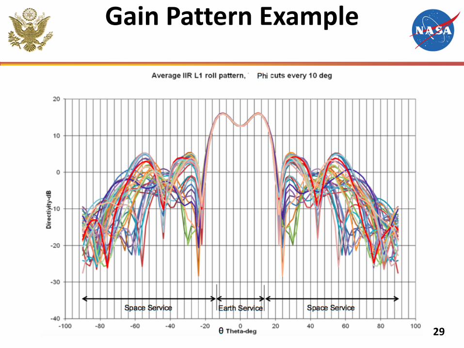
Gain Pattern Example
29
US Team Recommendations to
GNSS Providers
Long-term recommendations:
1. Baseline SSV specifications as part of all future constellation developments with
definitions and parameters that are common across all provider constellations
– Specification should strive to capture near-continuous availability such as what may be
provided by the aggregate GNSS signal (main & side lobes)
2. Providers should perform a comprehensive series of antenna tests and power
output measurements, pre-flight, to:
– Characterize constellation gain and pseudorange accuracy for the full antenna pattern
and to facilitate understanding of SSV specification margins
– Enable mission designers to derive mission PNT performance of spacecraft in the SSV
through mathematical models developed from antenna/power data
3. Perform on-orbit characterization & testing of SSV specified signal parameters
through dedicated flight experiments and mission data evaluation
4. Encourage development of spacecraft and formation flying missions in the SSV
5. Encourage active and consistent participation in all ICG SSV activities and
initiatives, including the current interoperable GNSS analyses 30
Closing Remarks
• NASA and all other space users increasingly rely on GNSS over an expanding range of orbital applications to serve Earth’s population in countless ways
• Current and future space missions in SSV orbits are becoming increasing reliant on near-continuous PNT sensing using GNSS
• To ensure stable, robust PNT in the SSV, providers should:
– Baseline SSV specifications as part of all future constellation developments using ICG-developed common definitions & parameters
– Specification should strive to capture near-continuous availability such as what may be provided by the aggregate GNSS signal (main & side lobes)
• WG-B is making significant progress in establishing an interoperable Global Navigation Satellite System (GNSS) Space Service Volume (SSV) through pre-work, analyses and regular meetings
• NASA and the USG is proud to work with the GNSS providers to contribute making GNSS services more accessible, interoperable, robust, and precise for all users, for the benefit of humanity
31
Backup Charts
32
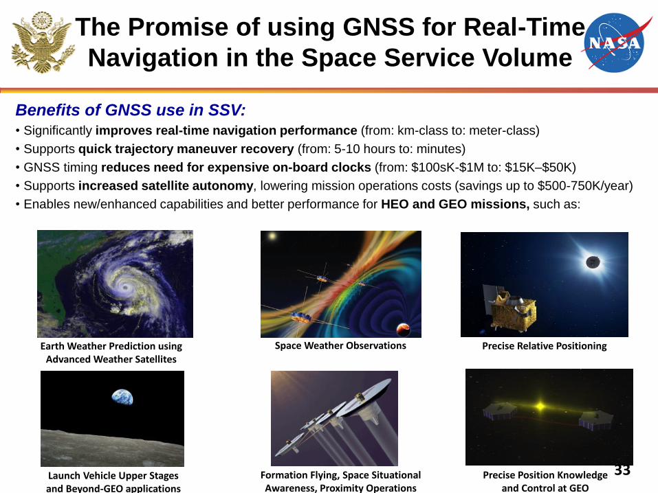
Benefits of GNSS use in SSV: • Significantly improves real-time navigation performance (from: km-class to: meter-class)
• Supports quick trajectory maneuver recovery (from: 5-10 hours to: minutes)
• GNSS timing reduces need for expensive on-board clocks (from: $100sK-$1M to: $15K–$50K)
• Supports increased satellite autonomy, lowering mission operations costs (savings up to $500-750K/year)
• Enables new/enhanced capabilities and better performance for HEO and GEO missions, such as:
The Promise of using GNSS for Real-Time
Navigation in the Space Service Volume
Formation Flying, Space Situational Awareness, Proximity Operations
Earth Weather Prediction using Advanced Weather Satellites
Launch Vehicle Upper Stages and Beyond-GEO applications
Space Weather Observations
Precise Position Knowledge and Control at GEO
Precise Relative Positioning
33
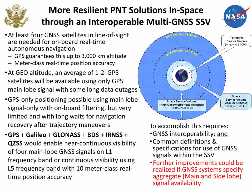
More Resilient PNT Solutions In-Space through an Interoperable Multi-GNSS SSV
•At least four GNSS satellites in line-of-sight are needed for on-board real-time autonomous navigation – GPS guarantees this up to 3,000 km altitude – Meter-class real-time position accuracy
•At GEO altitude, an average of 1-2 GPS satellites will be available using only GPS main lobe signal with some long data outages
•GPS-only positioning possible using main lobe signal-only with on-board filtering, but very limited and with long waits for navigation recovery after trajectory maneuvers
•GPS + Galileo + GLONASS + BDS + IRNSS + QZSS would enable near-continuous visibility of four main-lobe GNSS signals on L1 frequency band or continuous visibility using L5 frequency band with 10 meter-class real-time position accuracy
To accomplish this requires: •GNSS interoperability; and •Common definitions & specifications for use of GNSS signals within the SSV
•Further improvements could be realized if GNSS systems specify aggregate (Main and Side lobe) signal availability
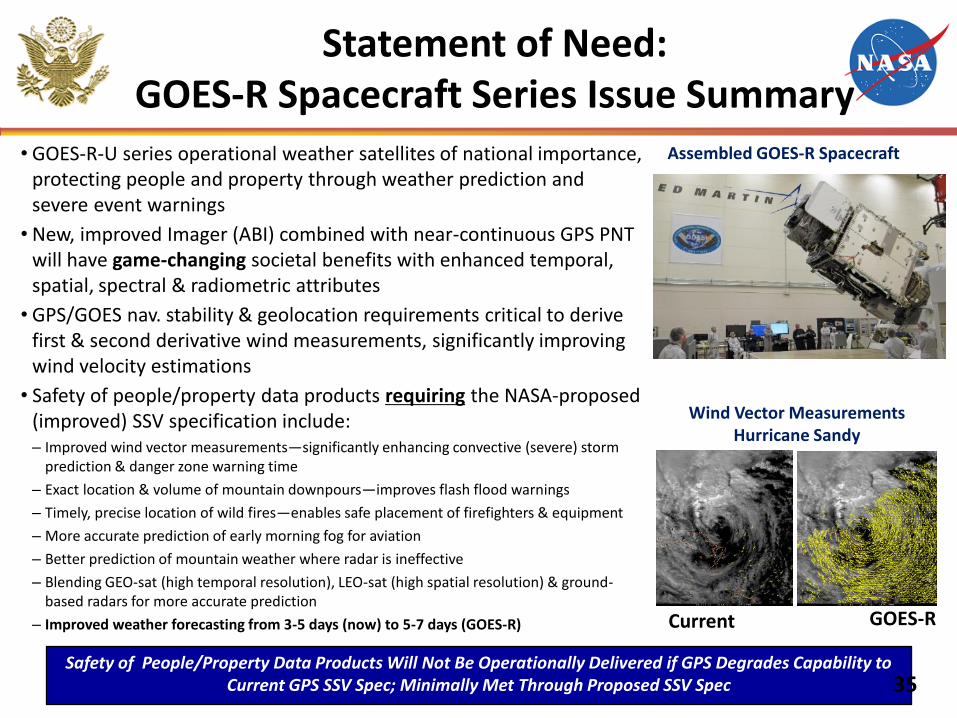
Statement of Need: GOES-R Spacecraft Series Issue Summary
• GOES-R-U series operational weather satellites of national importance, protecting people and property through weather prediction and severe event warnings
• New, improved Imager (ABI) combined with near-continuous GPS PNT will have game-changing societal benefits with enhanced temporal, spatial, spectral & radiometric attributes
• GPS/GOES nav. stability & geolocation requirements critical to derive first & second derivative wind measurements, significantly improving wind velocity estimations
• Safety of people/property data products requiring the NASA-proposed (improved) SSV specification include: – Improved wind vector measurements—significantly enhancing convective (severe) storm
prediction & danger zone warning time
– Exact location & volume of mountain downpours—improves flash flood warnings
– Timely, precise location of wild fires—enables safe placement of firefighters & equipment
– More accurate prediction of early morning fog for aviation
– Better prediction of mountain weather where radar is ineffective
– Blending GEO-sat (high temporal resolution), LEO-sat (high spatial resolution) & ground-based radars for more accurate prediction
– Improved weather forecasting from 3-5 days (now) to 5-7 days (GOES-R)
Assembled GOES-R Spacecraft
Current GOES-R
Wind Vector Measurements Hurricane Sandy
Safety of People/Property Data Products Will Not Be Operationally Delivered if GPS Degrades Capability to Current GPS SSV Spec; Minimally Met Through Proposed SSV Spec 35
36
Progress on Key Issues
• NASA & USAF partnership on implementation
– Joint NASA/USAF Memorandum of Agreement in coordination
– Defines roles & responsibilities for NASA and USAF through requirements definition and acquisition process
• Ensuring navigation resiliency
– NASA-proposed requirement is intended to protect use of critical GPS capabilities for space users in HEO/GEO
– Effort is not intended to establish GPS as a space user’s only navigation solution
– Resiliency is ensured through space vehicle applications of complementary PNT solutions – RF, optical, INS, etc.
37
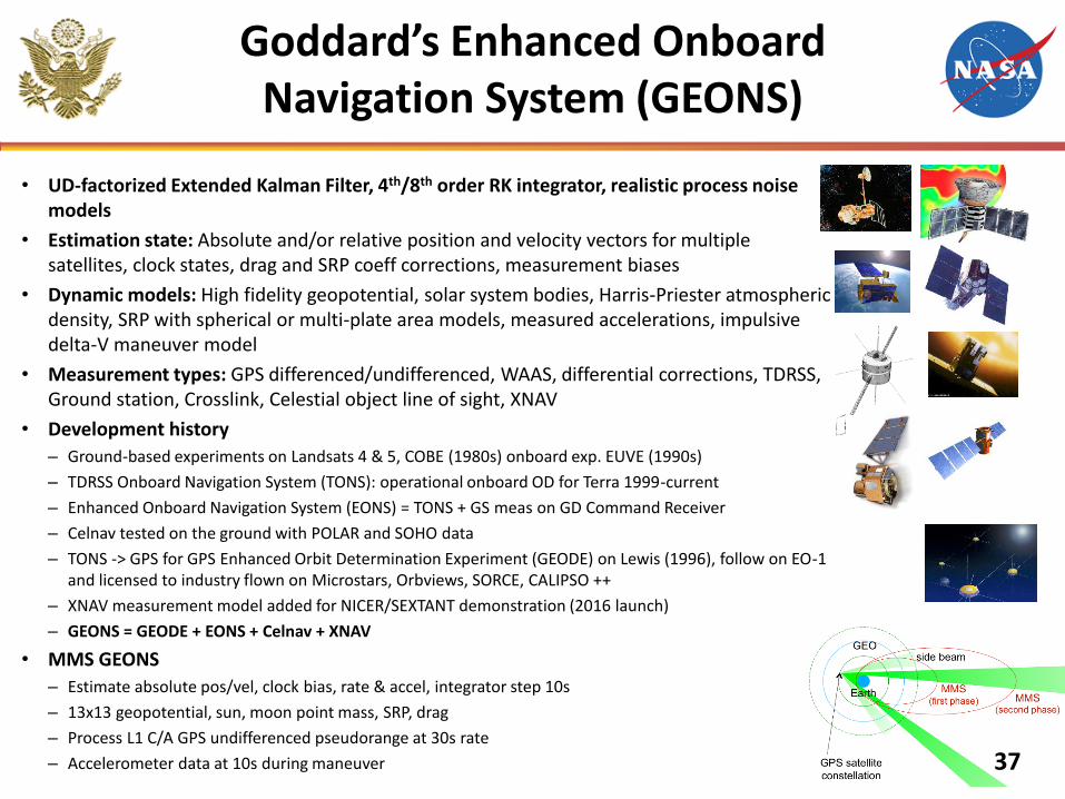
Goddard’s Enhanced Onboard Navigation System (GEONS)
• UD-factorized Extended Kalman Filter, 4th/8th order RK integrator, realistic process noise models
• Estimation state: Absolute and/or relative position and velocity vectors for multiple satellites, clock states, drag and SRP coeff corrections, measurement biases
• Dynamic models: High fidelity geopotential, solar system bodies, Harris-Priester atmospheric density, SRP with spherical or multi-plate area models, measured accelerations, impulsive delta-V maneuver model
• Measurement types: GPS differenced/undifferenced, WAAS, differential corrections, TDRSS, Ground station, Crosslink, Celestial object line of sight, XNAV
• Development history
– Ground-based experiments on Landsats 4 & 5, COBE (1980s) onboard exp. EUVE (1990s)
– TDRSS Onboard Navigation System (TONS): operational onboard OD for Terra 1999-current
– Enhanced Onboard Navigation System (EONS) = TONS + GS meas on GD Command Receiver
– Celnav tested on the ground with POLAR and SOHO data
– TONS -> GPS for GPS Enhanced Orbit Determination Experiment (GEODE) on Lewis (1996), follow on EO-1 and licensed to industry flown on Microstars, Orbviews, SORCE, CALIPSO ++
– XNAV measurement model added for NICER/SEXTANT demonstration (2016 launch)
– GEONS = GEODE + EONS + Celnav + XNAV
• MMS GEONS
– Estimate absolute pos/vel, clock bias, rate & accel, integrator step 10s
– 13x13 geopotential, sun, moon point mass, SRP, drag
– Process L1 C/A GPS undifferenced pseudorange at 30s rate
– Accelerometer data at 10s during maneuver
38
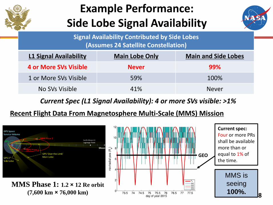
Example Performance: Side Lobe Signal Availability
Signal Availability Contributed by Side Lobes (Assumes 24 Satellite Constellation)
L1 Signal Availability Main Lobe Only Main and Side Lobes
4 or More SVs Visible Never 99%
1 or More SVs Visible 59% 100%
No SVs Visible 41% Never
Current Spec (L1 Signal Availability): 4 or more SVs visible: >1%
MMS is
seeing
100%.
GEO
Current spec: Four or more PRs shall be available more than or equal to 1% of the time.
Recent Flight Data From Magnetosphere Multi-Scale (MMS) Mission
MMS Phase 1: 1.2 × 12 Re orbit
(7,600 km × 76,000 km)
39
GPS Space Service Volume Specification History
•Mid-1990s—efforts started to develop a formal Space Service Volume –Discussion/debate about requiring “backside” antennas for space users
–Use of main lobe/side-lobe signals entertained as a no cost alternative
•1997-Present—Several space flight experiments, particularly the AMSAT-OSCAR-40 experiment demonstrated critical need to enhance space user requirements and SSV
•February 2000—GPS Operational Requirements Document (ORD), released with first space user requirements and description of SSV
–Shortcomings Did not cover mid-altitude users (above LEO but below GPS)
Did not cover users outside of the GEO equatorial plane
Only specified reqts on L1 signals (L2 and L5 have wider beam-width and therefore, better coverage)
•2000-2006—NASA/DoD team coordinated updated Space User reqmnts – Worked with SMC/GPE, Aerospace support staff & AFSPACE to assess
impacts of proposed requirements to GPS-III
– Government System Spec (SS-SYS-800) includes threshold & objective reqmnts
– Shortcomings: Developed with limited on-orbit experiment data & minimal understanding of
GPS satellite antenna patterns
Only specifies the main lobe signals, does not address side lobe signals
40
Key Endorsements
USAF SMC/SY (Space Superiority Systems)
• Letter of endorsement signed by Col Garrant, 26 Feb 2016.
• SMC/SY has documented program requirement.
• Requirement is unfunded at this time.
• SY currently performing analyses to document their actual required capability levels as compared to NASA’s proposed IFOR requirement.
NOAA
• Letter of endorsement from VADM Manson Brown (NOAA Deputy Administrator) to Gen Hyten & Maj Gen Thompson, 19 Apr 2016
• Confirms that GOES-R is reliant on GPS signals as captured in NASA’s proposed IFOR requirement
• Additionally, identifies EUMETSAT (EU) and Japanese weather satellites as reliant on increased signal availability
41
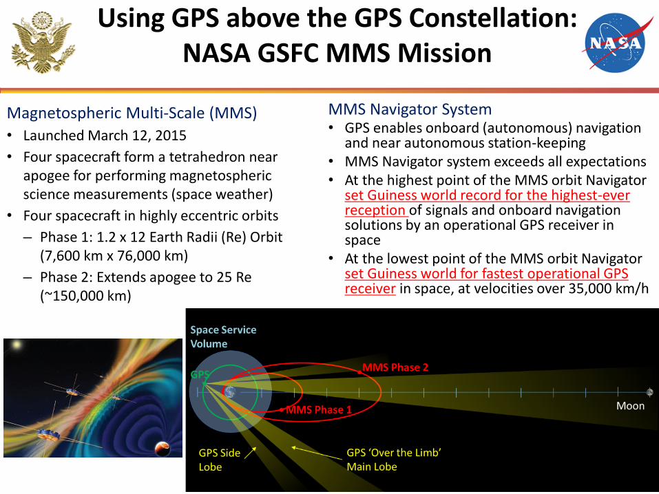
Magnetospheric Multi-Scale (MMS)
• Launched March 12, 2015
• Four spacecraft form a tetrahedron near apogee for performing magnetospheric science measurements (space weather)
• Four spacecraft in highly eccentric orbits
– Phase 1: 1.2 x 12 Earth Radii (Re) Orbit (7,600 km x 76,000 km)
– Phase 2: Extends apogee to 25 Re (~150,000 km)
MMS Navigator System • GPS enables onboard (autonomous) navigation
and near autonomous station-keeping • MMS Navigator system exceeds all expectations • At the highest point of the MMS orbit Navigator
set Guiness world record for the highest-ever reception of signals and onboard navigation solutions by an operational GPS receiver in space
• At the lowest point of the MMS orbit Navigator set Guiness world for fastest operational GPS receiver in space, at velocities over 35,000 km/h
Using GPS above the GPS Constellation: NASA GSFC MMS Mission
42
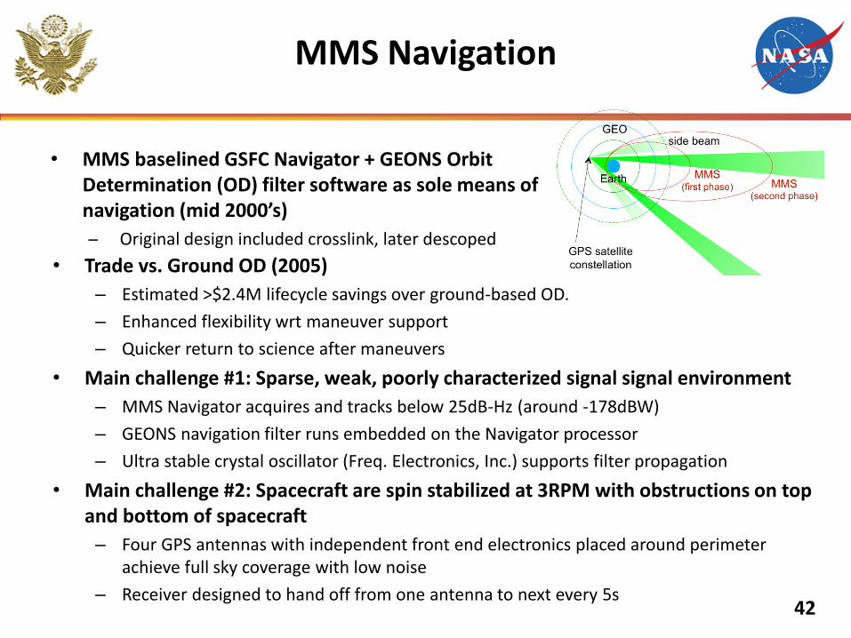
• Trade vs. Ground OD (2005)
– Estimated >$2.4M lifecycle savings over ground-based OD.
– Enhanced flexibility wrt maneuver support
– Quicker return to science after maneuvers
• Main challenge #1: Sparse, weak, poorly characterized signal signal environment
– MMS Navigator acquires and tracks below 25dB-Hz (around -178dBW)
– GEONS navigation filter runs embedded on the Navigator processor
– Ultra stable crystal oscillator (Freq. Electronics, Inc.) supports filter propagation
• Main challenge #2: Spacecraft are spin stabilized at 3RPM with obstructions on top and bottom of spacecraft
– Four GPS antennas with independent front end electronics placed around perimeter achieve full sky coverage with low noise
– Receiver designed to hand off from one antenna to next every 5s
• MMS baselined GSFC Navigator + GEONS Orbit Determination (OD) filter software as sole means of navigation (mid 2000’s)
Original design included crosslink, later descoped
MMS Navigation