Embed Size (px)
Citation preview
GNSS Space Service Volume Update—ICG WG-B Frank H. Bauer, Emergent Space Technologies for SCaN Program
Stephan Esterhuizen, JPL for SCaN Program
Human Exploration and Operations Mission Directorate (HEOMD), NASA
ICG-8, Dubai, UAE, November 12, 2013
Keeping the universe connected.
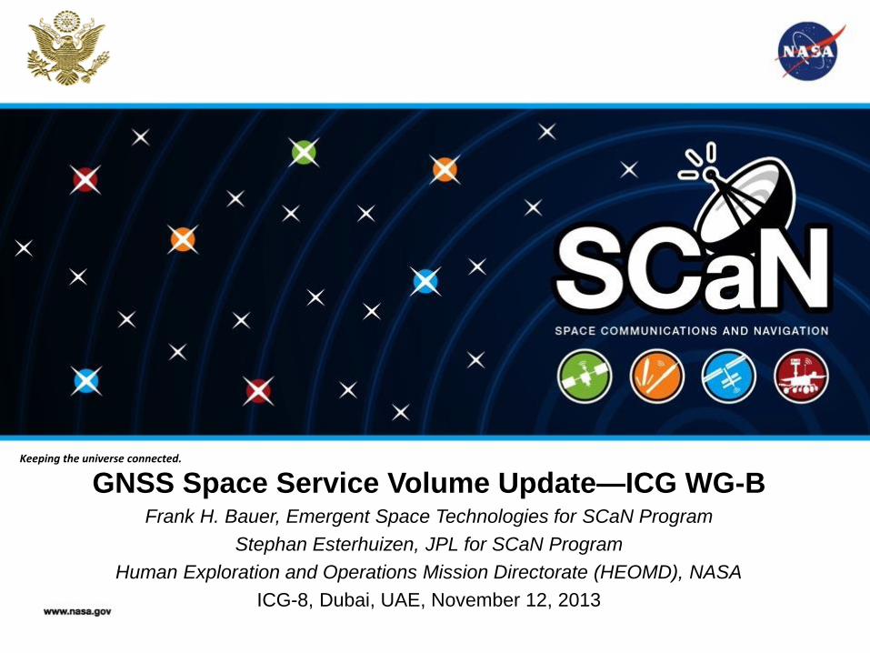
Expanding the GPS Space Service Volume (SSV) into a multi-GNSS SSV
• At least four GNSS satellites in line-of-sight are needed for on-board real-time autonomous navigation – GPS currently provides this up to 3,000 km
altitude – Enables better than 1-meter position accuracy in
real-time
• At Geosynchronous altitude, only one GPS satellite will be available at any given time. – GPS-only positioning still possible with on-board
filtering, but only up to approx. 100-meter absolute position accuracy.
– GPS + Galileo combined would enable 2-3 GNSS sats in-view at all times.
– GPS + Galileo + GLONASS would enable at least 4 GNSS sats in-view at all times.
– GPS + Galileo + GLONASS + Beidou would enable > 4 GNSS sats in view at all times. This provides best accuracy and, also, on-board integrity.
• However, this requires: – Interoperability among these the GNSS
constellations; and – Common definitions/specifications for use of
GNSS signals within the Space Service Volume (3,000 km to Geosynchronous altitude)
≥ 4 GPS satellites in line-of-sight here (surface to 3000 km)
Only 1-2 GPS satellites in line-
of-sight at Geosynchronous
orbit altitude
... but, if interoperable, then GPS + Galileo + GLONASS + Beidou provide > 4 GNSS sats in line-of-sight at Geosynchronous orbit altitude.
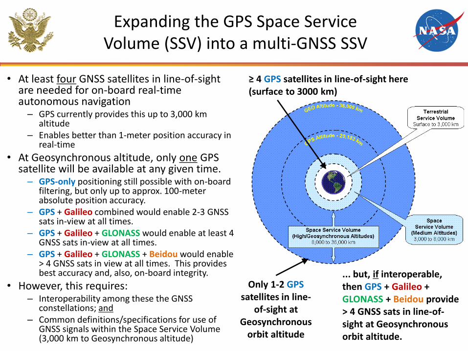
Why is an interoperable Space Service Volume important?
Global, interoperable Space Service Volume specifications are crucial for real-time GNSS navigation solutions in high Earth orbit
• Supports increased satellite autonomy for high Earth orbit missions, lowering mission operations costs
• Enables new/enhanced mission capabilities for High Earth orbit and geostationary orbit missions of the future, such as:
Formation Flying & Constellation Missions
Improved Weather Prediction using Advanced Weather Satellites
En-route Lunar Navigation Support
Space Weather Observations
Closer Spacing of Satellites in Geostationary Arc
Astrophysics Observations
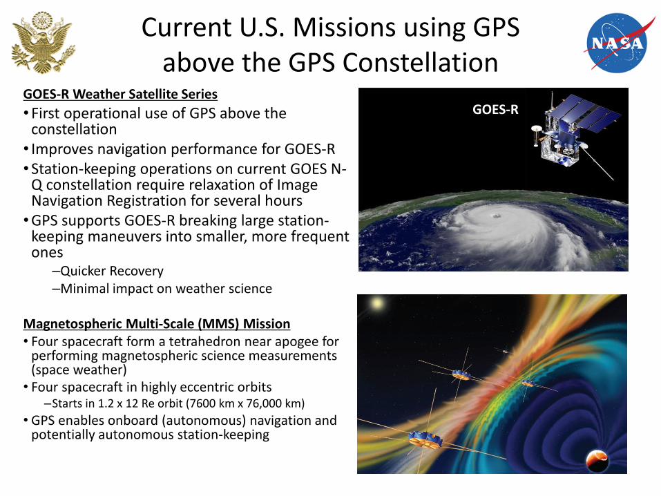
Current U.S. Missions using GPS above the GPS Constellation
GOES-R Weather Satellite Series
•First operational use of GPS above the constellation • Improves navigation performance for GOES-R •Station-keeping operations on current GOES N-
Q constellation require relaxation of Image Navigation Registration for several hours •GPS supports GOES-R breaking large station-
keeping maneuvers into smaller, more frequent ones
–Quicker Recovery –Minimal impact on weather science
Magnetospheric Multi-Scale (MMS) Mission • Four spacecraft form a tetrahedron near apogee for
performing magnetospheric science measurements (space weather)
• Four spacecraft in highly eccentric orbits –Starts in 1.2 x 12 Re orbit (7600 km x 76,000 km)
• GPS enables onboard (autonomous) navigation and potentially autonomous station-keeping
GOES-R
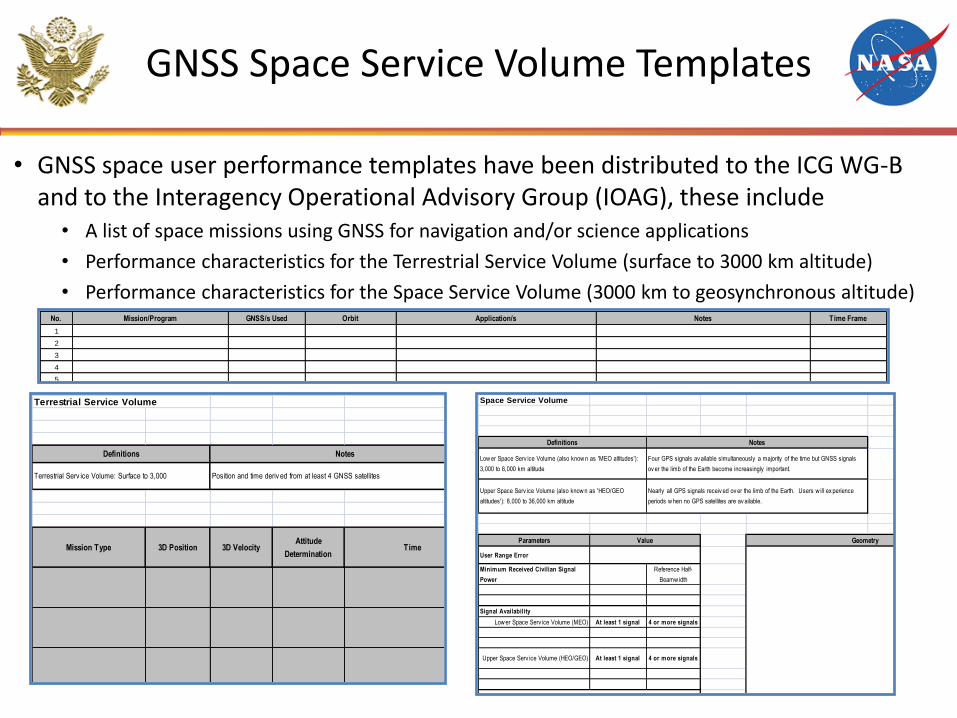
GNSS Space Service Volume Templates
• GNSS space user performance templates have been distributed to the ICG WG-B and to the Interagency Operational Advisory Group (IOAG), these include
• A list of space missions using GNSS for navigation and/or science applications
• Performance characteristics for the Terrestrial Service Volume (surface to 3000 km altitude)
• Performance characteristics for the Space Service Volume (3000 km to geosynchronous altitude)
No. Mission/Program GNSS/s Used Orbit Application/s Notes Time Frame
1
2
3
4
5
6
7
8
9
10
11
12
13
Terrestrial Service Volume
Mission Type 3D Position 3D VelocityAttitude
DeterminationTime
Notes:
Definitions
Terrestrial Serv ice Volume: Surface to 3,000
Notes
Position and time deriv ed from at least 4 GNSS satellites
Space Service Volume
Parameters
User Range Error
Minimum Received Civilian Signal
Power
Reference Half-
Beamw idth
Signal Availability
Low er Space Serv ice Volume (MEO) At least 1 signal 4 or more signals
Upper Space Serv ice Volume (HEO/GEO) At least 1 signal 4 or more signals
Value
Notes:
Geometry
Definitions
Low er Space Serv ice Volume (also know n as 'MEO altitudes'):
3,000 to 8,000 km altitude
Upper Space Serv ice Volume (also know n as 'HEO/GEO
altitudes'): 8,000 to 36,000 km altitude
Notes
Four GPS signals av ailable simultaneously a majority of the time but GNSS signals
ov er the limb of the Earth become increasingly important.
Nearly all GPS signals receiv ed ov er the limb of the Earth. Users w ill ex perience
periods w hen no GPS satellites are av ailable.
Realizing the Space Service Volume Vision The LONG and Winding Road
•Mid-1990s—efforts started to develop a formal Space Service Volume (SSV) with accompanying GPS signal and availability specification •February 2000—GPS Operational Requirements Document (ORD), released, included first space user requirements and description of SSV •1997-Present—Several space flight experiments, particularly the AMSAT-OSCAR-40 experiment, provided data to enhance space user requirements and SSV •2000-2010—NASA/DoD team coordinated set of updated Space User requirements to meet existing and future PNT needs
–Team worked with SMC/GPE, Aerospace support staff and AFSPACE to assess impacts of proposed requirements to GPS-III and to incorporate appropriate language into GPS-III Capabilities Description Document (CDD) –Threshold requirements correspond to performance from current
constellation (do no harm to space users) –Future space user needs included as Objective requirements –Continual Joint Program Office “zero impact” push back on CDD levels to GPS-
III baseline (Objective requirements) –Agreed to perform NASA/DoD study further as constellation design matures
with emphasis on moving towards Objective requirements –Government System Spec (SS-SYS-800) includes CDD threshold & objective
performance
Navigation Improvements Resulting from an Interoperable SSV
• Analysis performed to understand effects of augmenting GPS SSV signals with interoperable GNSS and SBAS
• Configuration analyzed: – GPS: 24 + 3 configuration
– Galileo: 27 satellite configuration
– GLONASS: 24 satellite configuration
– Beidou: 27 MEO, 5 GEO, 3 IGSO
– SBAS: 3 satellites for WAAS, EGNOS, SDCM (planned), QZSS(planned); GAGAN: first satellite launched
• Benefits observed: – >4 satellites observed 100% of time w/ all GNSS constellations & augmentations
– Factor of ~2-5 improvement in geometric dilution of precision (GDOP) when all constellations included
• Global, interoperable Space Service Volume specifications are crucial for real-time GNSS navigation solutions in high Earth orbit
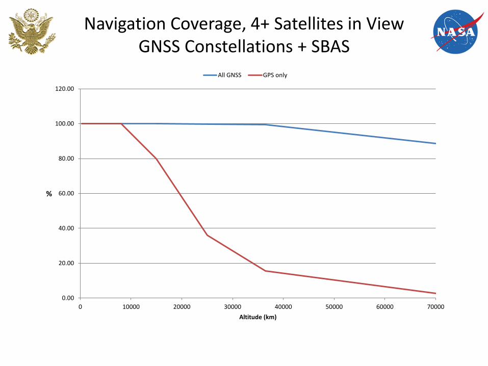
Navigation Coverage, 4+ Satellites in View GNSS Constellations + SBAS
0.00
20.00
40.00
60.00
80.00
100.00
120.00
0 10000 20000 30000 40000 50000 60000 70000
%
Altitude (km)
All GNSS GPS only
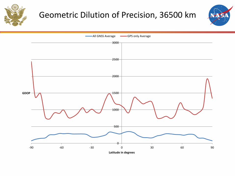
0
500
1000
1500
2000
2500
3000
-90 -60 -30 0 30 60 90
GDOP
Latitude in degrees
All GNSS Average GPS only Average
Geometric Dilution of Precision, 36500 km
Acknowledgements • Sincere thanks to all in the U.S. that have helped realize the Space
Service Volume vision: – USAF SMC GPS Program Office – NASA – Frank Bauer – Stephan Esterhuizen – Dale Force – John Rush – Jules McNeff – James Miller – Mike Moreau – A.J. Oria – Scott Pace – Park Temple – Larry Young
• Acknowledging, in advance, all outside the U.S. that recognize the in-space advantages of the Space Service Volume specification and provide leadership in developing a Space Service Volume specification for their GNSS constellation

Scientific Applications & Actions from Vienna 2013
Scientific Applications & Actions from Vienna 2013
• Applications: Ocean Altimetry and Terrestrial Reference Frame
• How to create: GPS Transmit Antenna Maps (group delay and phase vs. angle)
• Variation of antenna patterns between spacecraft and between blocks
• Recommendations from the Scientific Community
-100
-50
0
50
100
-12
-8
-4
0
4
8
12
1994.0 1996.0 1998.0 2000.0 2002.0 2004.0 2006.0
Time Series of T/P and Jason-1 Radial Antenna Offset EstimatesNoneIGSJPLBCDBCD
Nominal (Gipsy) Model
GRACE-Based GPS PCV Maps
mm
ppb
Year
TOPEX/Poseidon Jason-1
GRACE Data SpanUsed In
PCV Maps
D
-8.2953701Minimum
8.5058155Maximum
0.60300648Sum
19Points
0.031737183Mean
1.1129774Median
4.6419038RMS
4.7689914Std Deviation
22.743279Variance
1.0940817Std Error
-0.039184551Skewness
-0.92282638Kurtosis
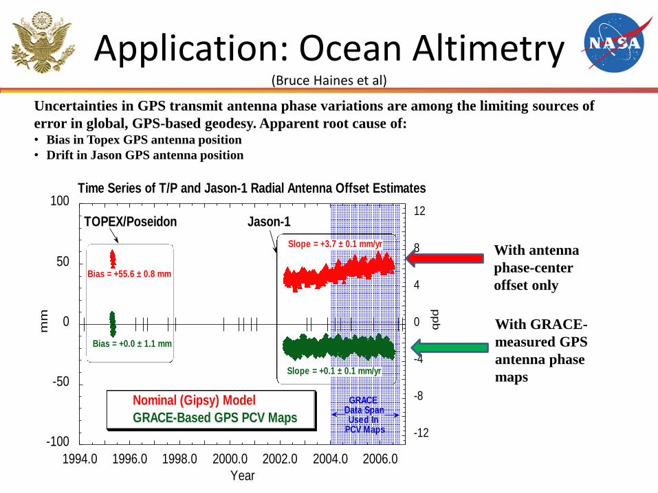
Slope = +3.7 ± 0.1 mm/yr
Slope = +0.1 ± 0.1 mm/yr
Bias = +55.6 ± 0.8 mm
B
48.259182Minimum
60.715157Maximum
1056.7383Sum
19Points
55.617803Mean
55.645386Median
55.716286RMS
3.4020173Std Deviation
11.573722Variance
0.78047629Std Error
-0.39930782Skewness
-0.57790671Kurtosis
Bias = +0.0 ± 1.1 mm
Application: Ocean Altimetry (Bruce Haines et al)
With antenna
phase-center
offset only
With GRACE-
measured GPS
antenna phase
maps
Uncertainties in GPS transmit antenna phase variations are among the limiting sources of
error in global, GPS-based geodesy. Apparent root cause of: • Bias in Topex GPS antenna position
• Drift in Jason GPS antenna position
-20
0
20
40
60
-4
-2
0
2
4
6
8
2002 2003 2004 2005 2006 2007 2008
mm
ppb
Years
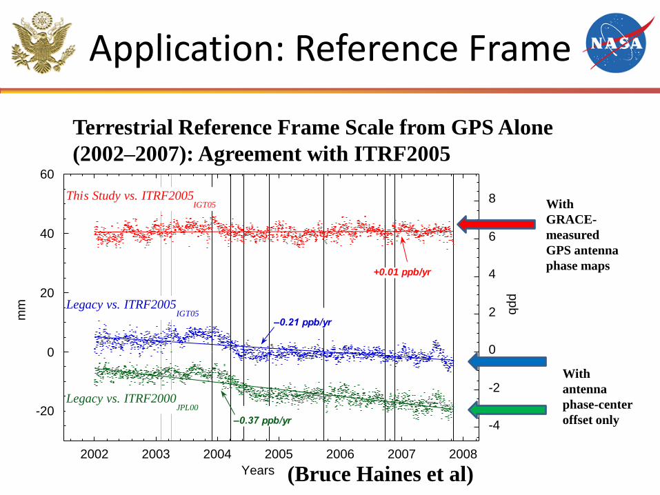
+0.01 ppb/yr
–0.21 ppb/yr
–0.37 ppb/yr
This Study vs. ITRF2005IGT05
Legacy vs. ITRF2005IGT05
Legacy vs. ITRF2000JPL00
Application: Reference Frame
Terrestrial Reference Frame Scale from GPS Alone
(2002–2007): Agreement with ITRF2005
With
GRACE-
measured
GPS antenna
phase maps
With
antenna
phase-center
offset only
(Bruce Haines et al)
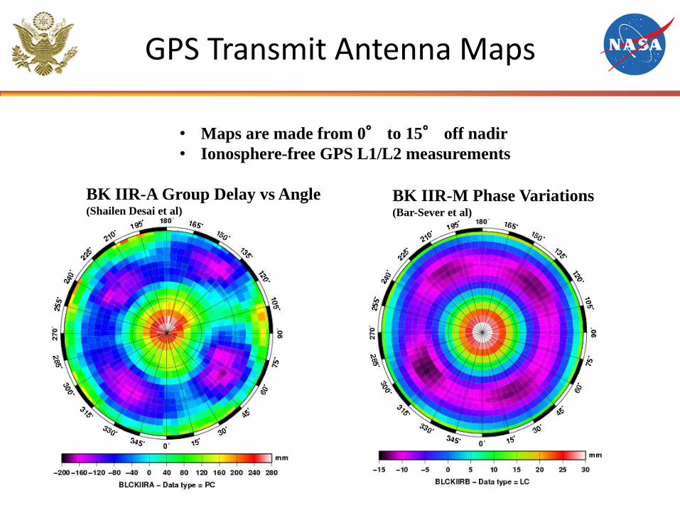
GPS Transmit Antenna Maps
BK IIR-A Group Delay vs Angle (Shailen Desai et al)
BK IIR-M Phase Variations (Bar-Sever et al)
• Maps are made from 0° to 15° off nadir
• Ionosphere-free GPS L1/L2 measurements
–15
0
5
10
15
0 4 8 12 16
Sampling of GPS Transmitter Beam Pattern
TERRESTRIAL NETWORK
GRACE (500 km)
JASON (1300 km)
% O
bs.
Nadir Angle (Deg.)
0 15
mm
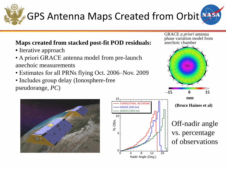
GRACE a priori antenna phase variation model from anechoic chamber
GPS Antenna Maps Created from Orbit
Off-nadir angle
vs. percentage
of observations
(Bruce Haines et al)
Maps created from stacked post-fit POD residuals:
• Iterative approach
• A priori GRACE antenna model from pre-launch
anechoic measurements
• Estimates for all PRNs flying Oct. 2006–Nov. 2009
• Includes group delay (Ionosphere-free
pseudorange, PC)
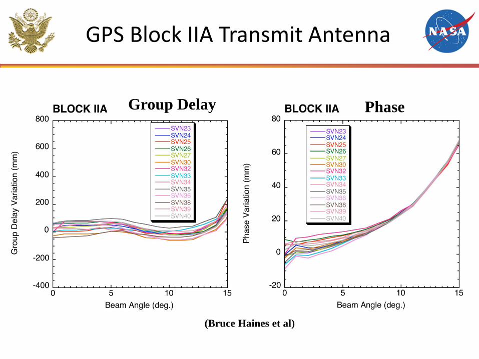
GPS Block IIA Transmit Antenna
Group Delay Phase
(Bruce Haines et al)
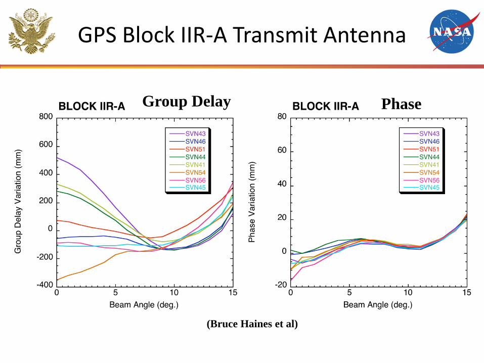
GPS Block IIR-A Transmit Antenna
Group Delay Phase
(Bruce Haines et al)
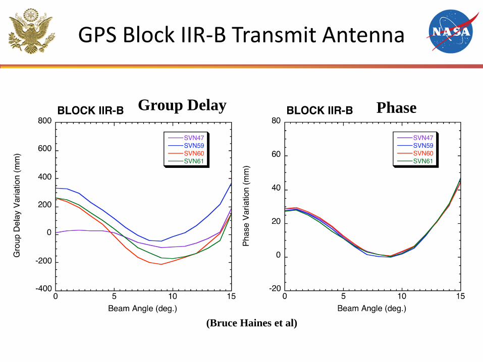
GPS Block IIR-B Transmit Antenna
Group Delay Phase
(Bruce Haines et al)
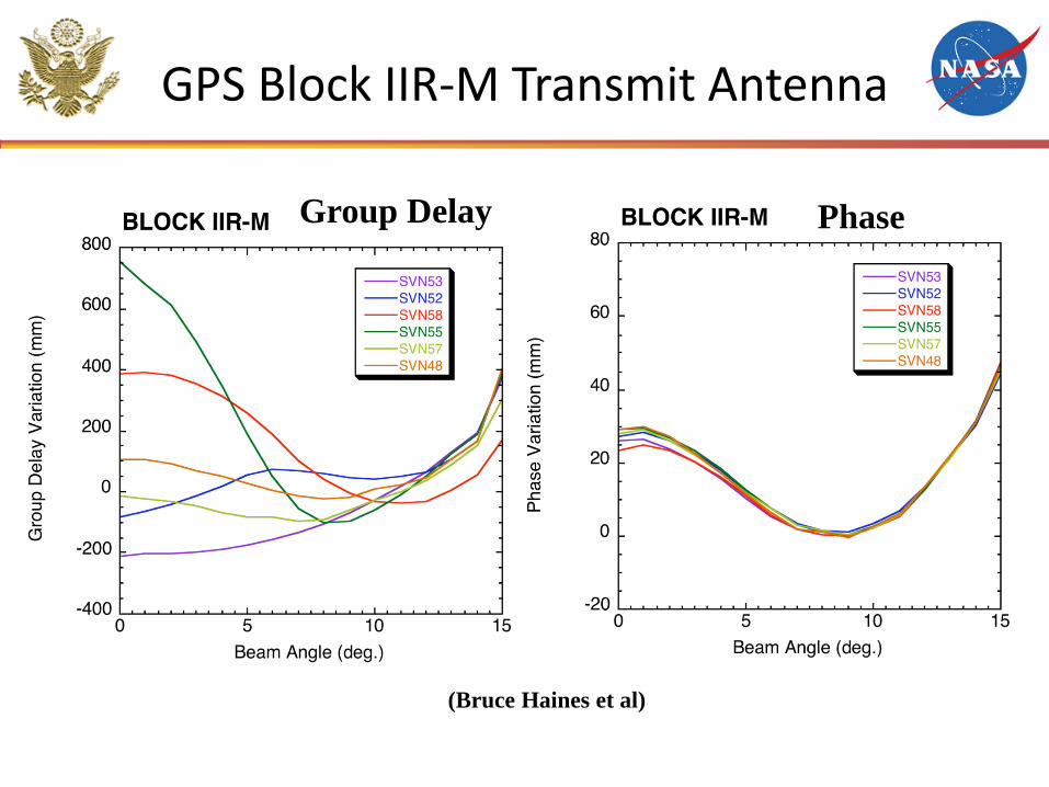
GPS Block IIR-M Transmit Antenna
Group Delay Phase
(Bruce Haines et al)
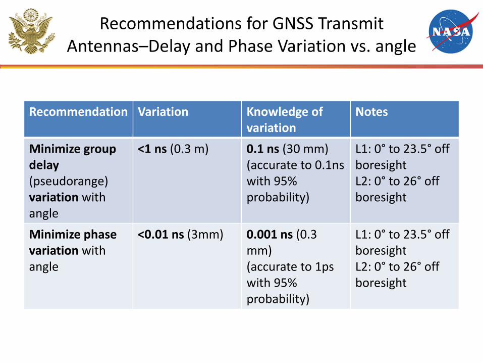
Recommendations for GNSS Transmit Antennas–Delay and Phase Variation vs. angle
Recommendation Variation Knowledge of variation
Notes
Minimize group delay (pseudorange) variation with angle
<1 ns (0.3 m) 0.1 ns (30 mm) (accurate to 0.1ns with 95% probability)
L1: 0° to 23.5° off boresight L2: 0° to 26° off boresight
Minimize phase variation with angle
<0.01 ns (3mm)
0.001 ns (0.3 mm) (accurate to 1ps with 95% probability)
L1: 0° to 23.5° off boresight L2: 0° to 26° off boresight
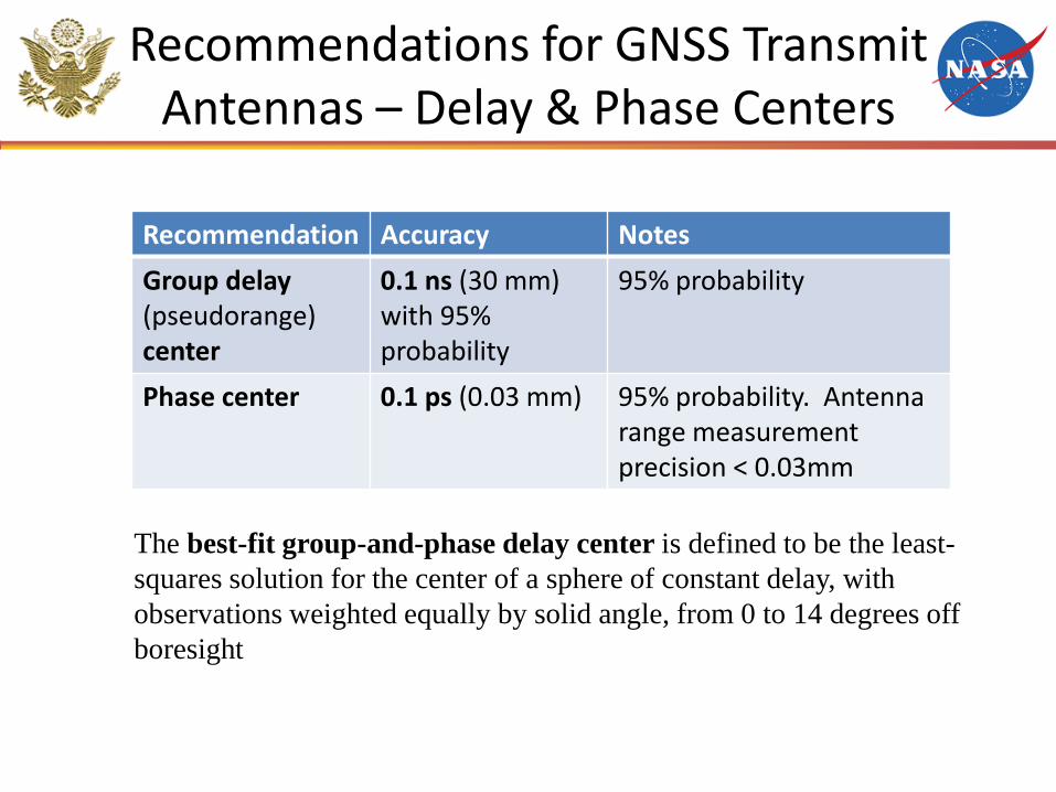
Recommendations for GNSS Transmit Antennas – Delay & Phase Centers
Recommendation Accuracy Notes
Group delay (pseudorange) center
0.1 ns (30 mm) with 95% probability
95% probability
Phase center 0.1 ps (0.03 mm)
95% probability. Antenna range measurement precision < 0.03mm
The best-fit group-and-phase delay center is defined to be the least-
squares solution for the center of a sphere of constant delay, with
observations weighted equally by solid angle, from 0 to 14 degrees off
boresight
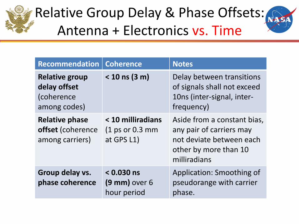
Relative Group Delay & Phase Offsets: Antenna + Electronics vs. Time
Recommendation Coherence Notes
Relative group delay offset (coherence among codes)
< 10 ns (3 m) Delay between transitions of signals shall not exceed 10ns (inter-signal, inter- frequency)
Relative phase offset (coherence among carriers)
< 10 milliradians (1 ps or 0.3 mm at GPS L1)
Aside from a constant bias, any pair of carriers may not deviate between each other by more than 10 milliradians
Group delay vs. phase coherence
< 0.030 ns (9 mm) over 6 hour period
Application: Smoothing of pseudorange with carrier phase.
Conclusion
• For the scientific community to realize the full potential of a satellite navigation system, it is crucial to provide a precise and stable system.
• Care must be taken when designing transmit antennas and spacecraft electronics due to variations between products.
• Tables of recommendations were provided, relating to designing of transmit antennas and satellite electronics.
Backups
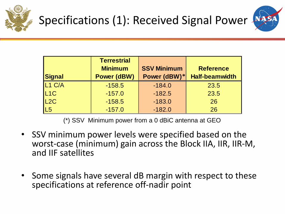
Specifications (1): Received Signal Power
• SSV minimum power levels were specified based on the worst-case (minimum) gain across the Block IIA, IIR, IIR-M, and IIF satellites
• Some signals have several dB margin with respect to these specifications at reference off-nadir point
Signal
Terrestrial
Minimum
Power (dBW)
SSV Minimum
Power (dBW)
Reference
Half-beamwidth
L1 C/A -158.5 -184.0 23.5
L1C -157.0 -182.5 23.5
L2C -158.5 -183.0 26
L5 -157.0 -182.0 26
(*) SSV Minimum power from a 0 dBiC antenna at GEO
*
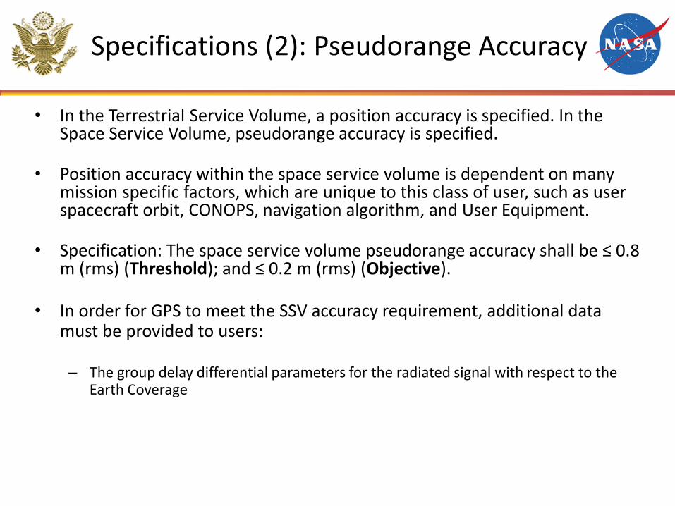
Specifications (2): Pseudorange Accuracy
• In the Terrestrial Service Volume, a position accuracy is specified. In the Space Service Volume, pseudorange accuracy is specified.
• Position accuracy within the space service volume is dependent on many mission specific factors, which are unique to this class of user, such as user spacecraft orbit, CONOPS, navigation algorithm, and User Equipment.
• Specification: The space service volume pseudorange accuracy shall be ≤ 0.8 m (rms) (Threshold); and ≤ 0.2 m (rms) (Objective).
• In order for GPS to meet the SSV accuracy requirement, additional data must be provided to users:
– The group delay differential parameters for the radiated signal with respect to the Earth Coverage
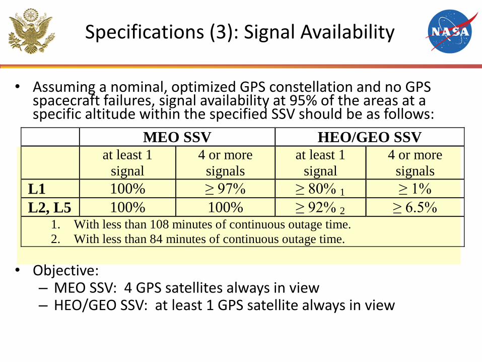
Specifications (3): Signal Availability
• Assuming a nominal, optimized GPS constellation and no GPS spacecraft failures, signal availability at 95% of the areas at a specific altitude within the specified SSV should be as follows:
• Objective: – MEO SSV: 4 GPS satellites always in view – HEO/GEO SSV: at least 1 GPS satellite always in view
MEO SSV HEO/GEO SSV
at least 1
signal
4 or more
signals
at least 1
signal
4 or more
signals
L1 100% ≥ 97% ≥ 80% 1 ≥ 1%
L2, L5 100% 100% ≥ 92% 2 ≥ 6.5% 1. With less than 108 minutes of continuous outage time.
2. With less than 84 minutes of continuous outage time.
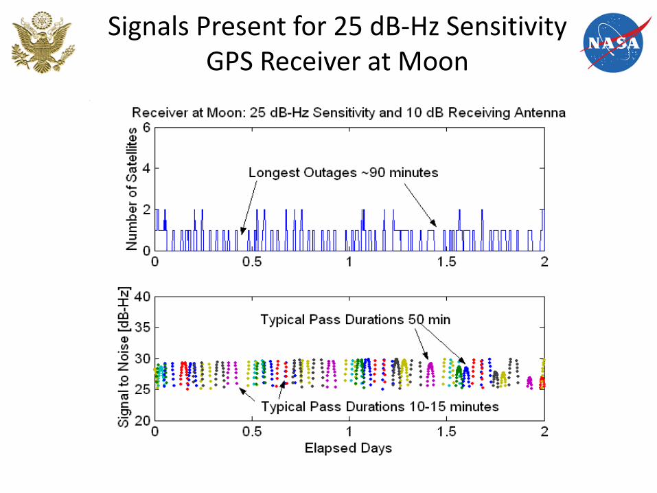
Signals Present for 25 dB-Hz Sensitivity GPS Receiver at Moon
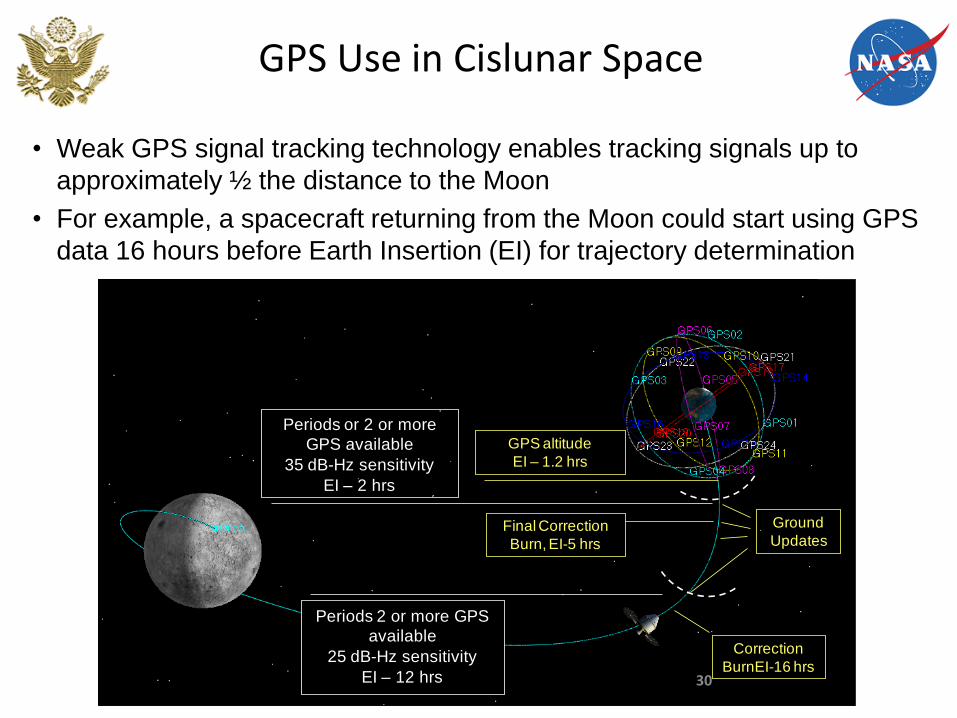
GPS Use in Cislunar Space
GPS altitude
EI – 1.2 hrs
Periods 2 or more GPS
available
25 dB-Hz sensitivity
EI – 12 hrs
Periods or 2 or more
GPS available
35 dB-Hz sensitivity
EI – 2 hrs
Final Correction
Burn, EI-5 hrs
Ground
Updates
Correction
BurnEI-16 hrs
• Weak GPS signal tracking technology enables tracking signals up to
approximately ½ the distance to the Moon
• For example, a spacecraft returning from the Moon could start using GPS
data 16 hours before Earth Insertion (EI) for trajectory determination
30