Embed Size (px)
Citation preview

Key Digital®, led by digital video pioneer Mike Tsinberg,
develops and manufactures high quality, cutting-edge
technology solutions for virtually all applications where
high-end video and control are important. Key Digital®
is at the forefront of the video industry for Home Theater
Retailers, Custom Installers, System Integrators,
Broadcasters, Manufacturers, and Consumers.
The Experts in Digital Video Technology and Solutions™
Rev 0 – June 2016
KD-Pro4x1KD-Pro2x1
Key Digital® Systems :: 521 East 3rd Street :: Mount Vernon, NY 10553
Phone : 914.667.9700 Fax : 914.668.8666 Web : www.keydigital.com
2/4 Inputs to 1 Output HDMI Switchers with Audio De-embedding of Analog L/R
Balanced/Unbalanced & Digital Coaxial Audio, supports Ultra HD/4K & HDCP 2.2
Operating Instructions
KD-Pro2x1KD-Pro4x1
KD-Pro2x1_4x1_Manual.indd 2-3 6/29/16 2:51 PM
4 1
Introduction
Key Digital® KD-Pro2x1/KD-Pro4x1 HDMI switchers are designed and engineered to
offer the best in quality, performance, and reliability, while providing a cost-effective
HDMI switching solution. The KD-Pro2x1/KD-Pro4x1 HDMI switchers are capable of
switching 2/4 independent Inputs/Sources to 1 Output/Zone and feature de-embedding
of HDMI audio for external distribution. KD-Pro2x1/KD-Pro4x1 support all SD, HD, VESA
and Ultra HD/4K video standards, including UHD/4K, 1080p/60, 1920x1200, 3D, and
support of HDCP 2.2 and HDR.
About the KD-Pro2x1/KD-Pro4x1
› HDMI Switching: 2/4 HDMI sources to 1 HDMI output › HDCP Licensing: Fully licensed and compatible with HDCP 2.2 › Resolution Support: Supports all SD, HD, and VESA (VGA, SVGA, XGA, WXGA,
SXGA, UXGA) › Ultra HD/4K Support: 4096x2160 or 3840x2160 30Hz at 4:4:4 and 60Hz at 4:4:4 › HDR (High Dynamic Range): More life-like images through a greater range of
luminance levels › Deep Color Support: Up to UHD/4K 30Hz 4:4:4/12 bits or 60Hz 4:4:4/8 bit › Audio De-Embedder: Audio from the selected HDMI input is de-embedded through
the Coax digital (PCM) or Analog L/R Balanced/Unbalanced › 3D Ready: Capability to pass 3D stereoscopic signal formats › Full Buffer System™: Manages TMDS re-clocking / signal re-generation,
HDCP authentication to source & display, and EDID Control handshake › EDID: Internal library with 15 default EDID handshakes for inputs, in addition to native
EDID data for Output/Display › TMDS re-clocking: Support for long HDMI connectivity using Key Digital® HDMI cables › Lossless Compressed Digital Audio: Dolby® TrueHD, Dolby® Digital Plus, DTS-HD Master
Audio™, and Dolby Atmos › Control: Front panel buttons/LEDs, Trigger In, Serial IR, Optical IR, RS-232 Control,
and TCP/IP Control › Control System Support: Key Digital® App ready. Compass Control® ready. Fully controllable
by all IR, RS-232, and TCP/IP supported control systems via open API.
Accessories
› Power Supply: KD-PS5V2ASC, 5V/2A, 100-240VAC, 50-60Hz, Interchangeable head, screw-type connector
› Rack Ears › Remote Control › (2) 6-Pin Terminal Blocks
Table of Contents
Introduction . . . . . . . . . . . . . . . . . . . . . . . . . . . . . . . . . . . . . . . . . . . . . . . . . . . . . . . . . . . . . .1
Quick Setup Guide . . . . . . . . . . . . . . . . . . . . . . . . . . . . . . . . . . . . . . . . . . . . . . . . . . . . . . . .2
Installation and Operation . . . . . . . . . . . . . . . . . . . . . . . . . . . . . . . . . . . . . . . . . . . . . . . . . . .3
Connections, Buttons, and LEDs. . . . . . . . . . . . . . . . . . . . . . . . . . . . . . . . . . . . . . . . . . . . . .5
Settings and Adjustments . . . . . . . . . . . . . . . . . . . . . . . . . . . . . . . . . . . . . . . . . . . . . . . . . . .8
Communication Protocol . . . . . . . . . . . . . . . . . . . . . . . . . . . . . . . . . . . . . . . . . . . . . . . . . . .10
Specifications . . . . . . . . . . . . . . . . . . . . . . . . . . . . . . . . . . . . . . . . . . . . . . . . . . . . . . . . . . .12
Important Product Warnings & Safety Instructions: . . . . . . . . . . . . . . . . . . . . . . . . . . . . . . .13
How to Contact Key Digital®. . . . . . . . . . . . . . . . . . . . . . . . . . . . . . . . . . . . . . . . . . . . . . . .14
Warranty Information . . . . . . . . . . . . . . . . . . . . . . . . . . . . . . . . . . . . . . . . . . . . . . . . . . . . . .14
© 2016 Key Digital, Inc. All rights reserved.
Always follow the instructions provided in this Operating Manual.
Please check the Key Digital Website for the most up-to-date Manual.
KD-Pro2x1_4x1_Manual.indd 4-1 6/29/16 2:51 PM
2 3
Multi-Zone Amp
HDMI
HDMI
HDMI
HDMI
HDMI
HD
MI
HD
MI
HD
MI
KD-Pro4x1
KD-Pro4x1
WiFi Router
Master Controller
Ethernet
RJ45
RJ45
RJ45
WiFi
KD-MC1000
WiFi Router
Ethernet
RJ45
RJ45
RJ45
WiFi
KD-MC1000
Multi-Zone Amp
4K Media Server
Visualizer
Laptop 1
Laptop 2
4K Media Server Visualizer Laptop 1 Laptop 2
HDMI
HD
MI
PCM / L/R
Aud
io
Speakers
Speakers
Installation and OperationBefore permanently securing the unit for final installation, test for proper operation of the unit and cables in your system. It is recommended that you leave enough ventilation space to provide sufficient airflow and cooling.
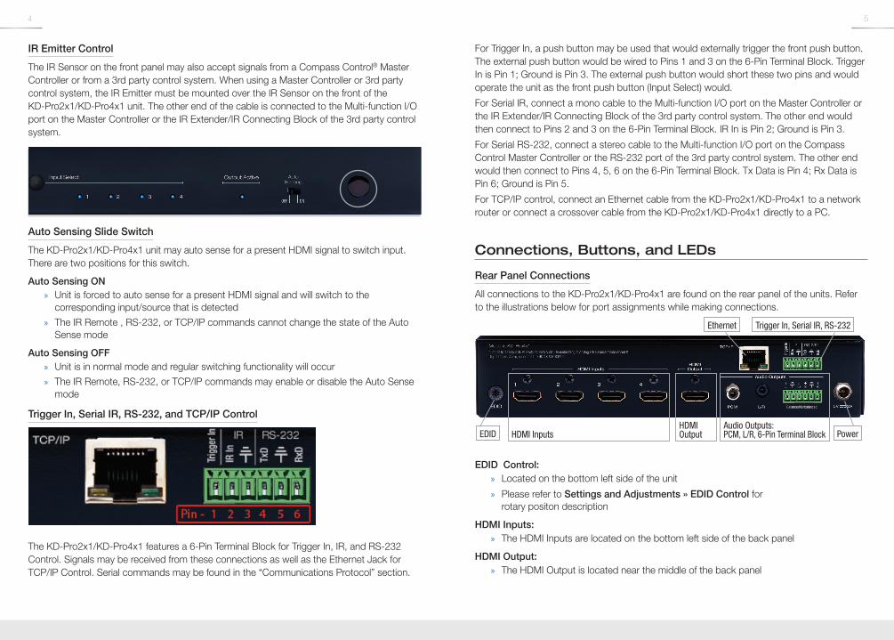
Pushbutton Control
The KD-Pro2x1/KD-Pro4x1 unit may be controlled via the push button on the front of the unit. Select the desired input by pressing the “Input Select” button. The front LED indicators (1, 2, 3, 4) correspond to the input that has been selected.
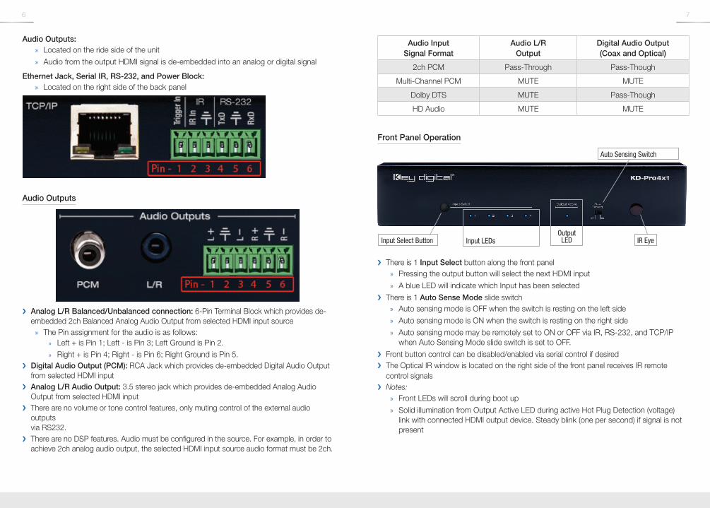
IR Remote Control
The KD-Pro2x1/KD-Pro4x1 may also be operated using the IR Remote provided with the unit (the remote is powered by a CR2025 Battery). The KD-Pro2x1/KD-Pro4x1 switcher features an IR sensor on the front of the unit for reception of signals. Please note that some remote buttons may have no functionality. For example, the unit does not power down, therefore the Power Button has no function.
Input Select
Input Select Scroll Up/Down
R1, R2, R3 Numeric Keypad
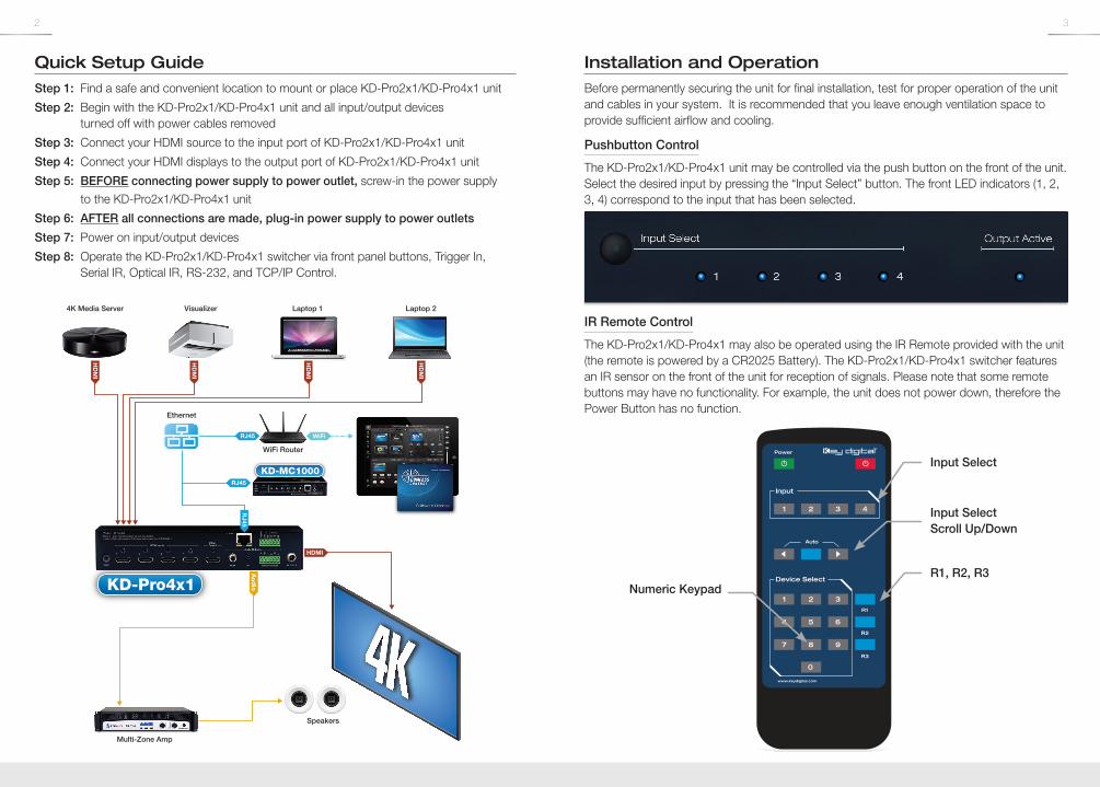
Quick Setup GuideStep 1: Find a safe and convenient location to mount or place KD-Pro2x1/KD-Pro4x1 unit
Step 2: Begin with the KD-Pro2x1/KD-Pro4x1 unit and all input/output devices turned off with power cables removed
Step 3: Connect your HDMI source to the input port of KD-Pro2x1/KD-Pro4x1 unit
Step 4: Connect your HDMI displays to the output port of KD-Pro2x1/KD-Pro4x1 unit
Step 5: BEFORE connecting power supply to power outlet, screw-in the power supply to the KD-Pro2x1/KD-Pro4x1 unit
Step 6: AFTER all connections are made, plug-in power supply to power outlets
Step 7: Power on input/output devices
Step 8: Operate the KD-Pro2x1/KD-Pro4x1 switcher via front panel buttons, Trigger In, Serial IR, Optical IR, RS-232, and TCP/IP Control.
KD-Pro2x1_4x1_Manual.indd 2-3 6/29/16 2:51 PM
4 5
IR Emitter Control
The IR Sensor on the front panel may also accept signals from a Compass Control® Master Controller or from a 3rd party control system. When using a Master Controller or 3rd party control system, the IR Emitter must be mounted over the IR Sensor on the front of the KD-Pro2x1/KD-Pro4x1 unit. The other end of the cable is connected to the Multi-function I/O port on the Master Controller or the IR Extender/IR Connecting Block of the 3rd party control system.
Auto Sensing Slide Switch
The KD-Pro2x1/KD-Pro4x1 unit may auto sense for a present HDMI signal to switch input. There are two positions for this switch.
Auto Sensing ON » Unit is forced to auto sense for a present HDMI signal and will switch to the
corresponding input/source that is detected
» The IR Remote , RS-232, or TCP/IP commands cannot change the state of the Auto Sense mode
Auto Sensing OFF » Unit is in normal mode and regular switching functionality will occur
» The IR Remote, RS-232, or TCP/IP commands may enable or disable the Auto Sense mode
Trigger In, Serial IR, RS-232, and TCP/IP Control
The KD-Pro2x1/KD-Pro4x1 features a 6-Pin Terminal Block for Trigger In, IR, and RS-232 Control. Signals may be received from these connections as well as the Ethernet Jack for TCP/IP Control. Serial commands may be found in the “Communications Protocol” section.
For Trigger In, a push button may be used that would externally trigger the front push button. The external push button would be wired to Pins 1 and 3 on the 6-Pin Terminal Block. Trigger In is Pin 1; Ground is Pin 3. The external push button would short these two pins and would operate the unit as the front push button (Input Select) would.
For Serial IR, connect a mono cable to the Multi-function I/O port on the Master Controller or the IR Extender/IR Connecting Block of the 3rd party control system. The other end would then connect to Pins 2 and 3 on the 6-Pin Terminal Block. IR In is Pin 2; Ground is Pin 3.
For Serial RS-232, connect a stereo cable to the Multi-function I/O port on the Compass Control Master Controller or the RS-232 port of the 3rd party control system. The other end would then connect to Pins 4, 5, 6 on the 6-Pin Terminal Block. Tx Data is Pin 4; Rx Data is Pin 6; Ground is Pin 5.
For TCP/IP control, connect an Ethernet cable from the KD-Pro2x1/KD-Pro4x1 to a network router or connect a crossover cable from the KD-Pro2x1/KD-Pro4x1 directly to a PC.
Connections, Buttons, and LEDs
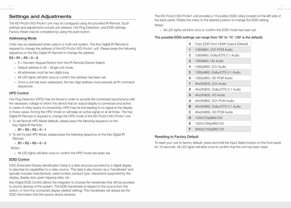
Rear Panel Connections
All connections to the KD-Pro2x1/KD-Pro4x1 are found on the rear panel of the units. Refer to the illustrations below for port assignments while making connections.
HDMI InputsAudio Outputs: PCM, L/R, 6-Pin Terminal Block
HDMI OutputEDID
Ethernet Trigger In, Serial IR, RS-232
Power
EDID Control: » Located on the bottom left side of the unit
» Please refer to Settings and Adjustments » EDID Control for rotary positon description
HDMI Inputs: » The HDMI Inputs are located on the bottom left side of the back panel
HDMI Output: » The HDMI Output is located near the middle of the back panel
KD-Pro2x1_4x1_Manual.indd 4-5 6/29/16 2:51 PM
6 7
Audio Outputs: » Located on the ride side of the unit
» Audio from the output HDMI signal is de-embedded into an analog or digital signal
Ethernet Jack, Serial IR, RS-232, and Power Block: » Located on the right side of the back panel
Audio Outputs
› Analog L/R Balanced/Unbalanced connection: 6-Pin Terminal Block which provides de-embedded 2ch Balanced Analog Audio Output from selected HDMI input source
» The Pin assignment for the audio is as follows: » Left + is Pin 1; Left - is Pin 3; Left Ground is Pin 2. » Right + is Pin 4; Right - is Pin 6; Right Ground is Pin 5.
› Digital Audio Output (PCM): RCA Jack which provides de-embedded Digital Audio Output from selected HDMI input
› Analog L/R Audio Output: 3.5 stereo jack which provides de-embedded Analog Audio Output from selected HDMI input
› There are no volume or tone control features, only muting control of the external audio outputs via RS232.
› There are no DSP features. Audio must be configured in the source. For example, in order to achieve 2ch analog audio output, the selected HDMI input source audio format must be 2ch.
Audio Input Signal Format
Audio L/R Output
Digital Audio Output (Coax and Optical)
2ch PCM Pass-Through Pass-Though
Multi-Channel PCM MUTE MUTE
Dolby DTS MUTE Pass-Though
HD Audio MUTE MUTE
Front Panel Operation
Input LEDsOutput
LEDInput Select Button
Auto Sensing Switch
IR Eye
› There is 1 Input Select button along the front panel » Pressing the output button will select the next HDMI input
» A blue LED will indicate which Input has been selected
› There is 1 Auto Sense Mode slide switch » Auto sensing mode is OFF when the switch is resting on the left side
» Auto sensing mode is ON when the switch is resting on the right side
» Auto sensing mode may be remotely set to ON or OFF via IR, RS-232, and TCP/IP when Auto Sensing Mode slide switch is set to OFF.
› Front button control can be disabled/enabled via serial control if desired › The Optical IR window is located on the right side of the front panel receives IR remote
control signals › Notes:
» Front LEDs will scroll during boot up
» Solid illumination from Output Active LED during active Hot Plug Detection (voltage) link with connected HDMI output device. Steady blink (one per second) if signal is not present
KD-Pro2x1_4x1_Manual.indd 6-7 6/29/16 2:51 PM
8 9
Settings and AdjustmentsThe KD-Pro2x1/KD-Pro4x1 unit may be configured using the provided IR Remote. Such settings and adjustments include unit address, Hot Plug Detection, and EDID settings. Factory Reset may be completed by using the push button.
Addressing Mode
Units may be addressed when used in a multi-unit system. The Key Digital IR Remote is required to change the address of the KD-Pro2x1/KD-Pro4x1 unit. Please press the following sequence on the Key Digital IR Remote to change the address.
R3 » R1 » R2 » X » X
» X = Numeric Keypad Button from the IR Remote (Device Select)
» Default address is 00 – Single unit mode.
» All addresses must be two digits long
» All LED lights will blink once to confirm the address has been set.
» Once a unit has been addressed, the two digit address must precede all IR command sequences
HPD Control
Hot Plug Detection (HPD) may be forced in order to provide the connected input/source with the necessary voltage to inform the device that an output/display is connected and active. In cases of many layers of connectivity, HPD may be lost leading to no signal at the display. In those cases, forcing the HPD mode on will keep an active signal on at all times. The Key Digital IR Remote is required to change the HPD mode of the KD-Pro2x1/KD-Pro4x1 unit.
› To set Normal HPD Mode (default), please press the following sequence on the Key Digital IR Remote:
» R1 » R2 » R3 » 0 » 1
› To set Forced HPD Mode, please press the following sequence on the Key Digital IR Remote:
» R1 » R2 » R3 » 0 » 0
Notes:
» All LED lights will blink once to confirm the HPD mode has been set.
EDID Control
EDID (Extended Display Identification Data) is a data structure provided by a digital display to describe its capabilities to a video source. This data is also known as a “handshake” and typically includes manufacturer, serial number, product type, resolutions supported by the display, display size, pixel mapping data, etc.
Key Digital EDID Control allows the integrator to choose the handshake that will be provided to source devices of the system. The EDID handshake is relayed to the source from the switch, or from the connected display (default setting). This handshake will always be the EDID information that the source device receives.
The KD-Pro2x1/KD-Pro4x1 unit provides a 16 position EDID rotary located on the left side of the back panel. Rotate the rotary to the desired position to change the EDID setting.
Notes:
» All LED lights will blink once to confirm the EDID mode has been set.
The possible EDID settings can range from ‘00’ to ‘15’. (‘00’ is the default).
0 Copy EDID from HDMI Output (Default)
1 1080i@60, 2Ch PCM Audio
2 1080i@60, Dolby/DTS 5.1 Audio
3 1080i@60, HD Audio
4 1080p@60, 2Ch Audio
5 1080p@60, Dolby/DTS 5.1 Audio
6 1080p@60, HD PCM Audio
7 4Kx2K@30, 2Ch Audio
8 4Kx2K@30, Dolby/DTS 5.1 Audio
9 4Kx2K@30, HD Audio
A 4Kx2K@60, 2Ch PCM Audio
B 4Kx2K@60, Dolby/DTS 5.1 Audio
C 4Kx2K@60, HD PCM Audio
D 1280x720p@60 DVI
E 1920x1080p@60 DVI
F 3840x2160p@60 DVI
Resetting to Factory Default
To reset your unit to factory default, press and hold the Input Select button on the front panel for 10 seconds. All LED lights will blink once to confirm that the unit has been reset.
KD-Pro2x1_4x1_Manual.indd 8-9 6/29/16 2:51 PM
10 11
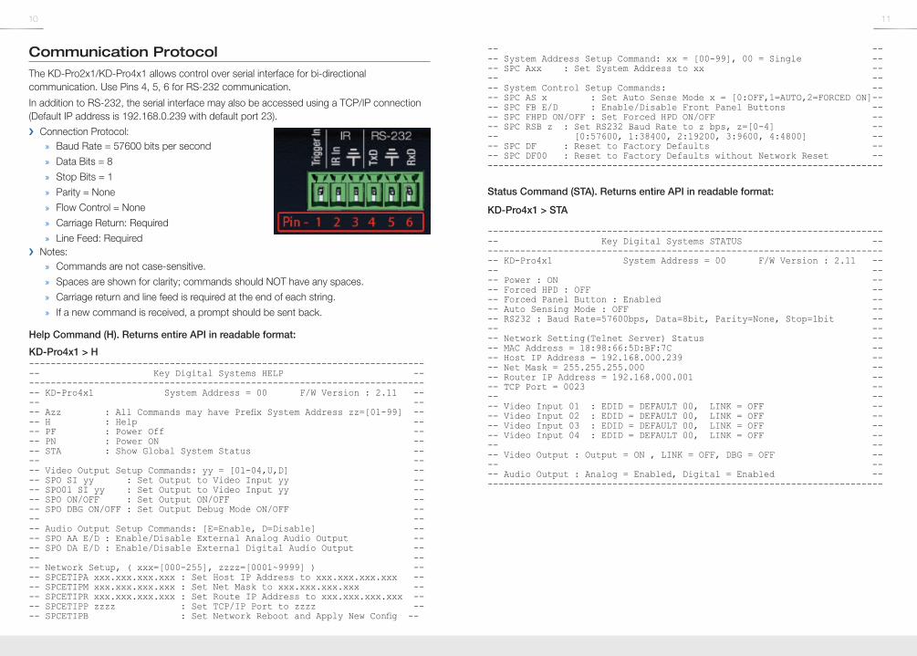
Communication ProtocolThe KD-Pro2x1/KD-Pro4x1 allows control over serial interface for bi-directional communication. Use Pins 4, 5, 6 for RS-232 communication.
In addition to RS-232, the serial interface may also be accessed using a TCP/IP connection (Default IP address is 192.168.0.239 with default port 23).
› Connection Protocol: » Baud Rate = 57600 bits per second
» Data Bits = 8
» Stop Bits = 1
» Parity = None
» Flow Control = None
» Carriage Return: Required
» Line Feed: Required › Notes:
» Commands are not case-sensitive.
» Spaces are shown for clarity; commands should NOT have any spaces.
» Carriage return and line feed is required at the end of each string.
» If a new command is received, a prompt should be sent back.
Help Command (H). Returns entire API in readable format:
KD-Pro4x1 > H--------------------------------------------------------------------------- Key Digital Systems HELP ----------------------------------------------------------------------------- KD-Pro4x1 System Address = 00 F/W Version : 2.11 ---- ---- Azz : All Commands may have Prefix System Address zz=[01-99] ---- H : Help ---- PF : Power Off ---- PN : Power ON ---- STA : Show Global System Status ---- ---- Video Output Setup Commands: yy = [01-04,U,D] ---- SPO SI yy : Set Output to Video Input yy ---- SPO01 SI yy : Set Output to Video Input yy ---- SPO ON/OFF : Set Output ON/OFF ---- SPO DBG ON/OFF : Set Output Debug Mode ON/OFF ---- ---- Audio Output Setup Commands: [E=Enable, D=Disable] ---- SPO AA E/D : Enable/Disable External Analog Audio Output ---- SPO DA E/D : Enable/Disable External Digital Audio Output ---- ---- Network Setup, ( xxx=[000-255], zzzz=[0001~9999] ) ---- SPCETIPA xxx.xxx.xxx.xxx : Set Host IP Address to xxx.xxx.xxx.xxx ---- SPCETIPM xxx.xxx.xxx.xxx : Set Net Mask to xxx.xxx.xxx.xxx ---- SPCETIPR xxx.xxx.xxx.xxx : Set Route IP Address to xxx.xxx.xxx.xxx ---- SPCETIPP zzzz : Set TCP/IP Port to zzzz ---- SPCETIPB : Set Network Reboot and Apply New Config --
-- ---- System Address Setup Command: xx = [00-99], 00 = Single ---- SPC Axx : Set System Address to xx ---- ---- System Control Setup Commands: ---- SPC AS x : Set Auto Sense Mode x = [0:OFF,1=AUTO,2=FORCED ON]---- SPC FB E/D : Enable/Disable Front Panel Buttons ---- SPC FHPD ON/OFF : Set Forced HPD ON/OFF ---- SPC RSB z : Set RS232 Baud Rate to z bps, z=[0-4] ---- [0:57600, 1:38400, 2:19200, 3:9600, 4:4800] ---- SPC DF : Reset to Factory Defaults ---- SPC DF00 : Reset to Factory Defaults without Network Reset ---------------------------------------------------------------------------
Status Command (STA). Returns entire API in readable format:
KD-Pro4x1 > STA
--------------------------------------------------------------------------- Key Digital Systems STATUS ----------------------------------------------------------------------------- KD-Pro4x1 System Address = 00 F/W Version : 2.11 ---- ---- Power : ON ---- Forced HPD : OFF ---- Forced Panel Button : Enabled ---- Auto Sensing Mode : OFF ---- RS232 : Baud Rate=57600bps, Data=8bit, Parity=None, Stop=1bit ---- ---- Network Setting(Telnet Server) Status ---- MAC Address = 18:98:66:5D:BF:7C ---- Host IP Address = 192.168.000.239 ---- Net Mask = 255.255.255.000 ---- Router IP Address = 192.168.000.001 ---- TCP Port = 0023 ---- ---- Video Input 01 : EDID = DEFAULT 00, LINK = OFF ---- Video Input 02 : EDID = DEFAULT 00, LINK = OFF ---- Video Input 03 : EDID = DEFAULT 00, LINK = OFF ---- Video Input 04 : EDID = DEFAULT 00, LINK = OFF ---- ---- Video Output : Output = ON , LINK = OFF, DBG = OFF ---- ---- Audio Output : Analog = Enabled, Digital = Enabled ---------------------------------------------------------------------------
KD-Pro2x1_4x1_Manual.indd 10-11 6/29/16 2:51 PM
12 13
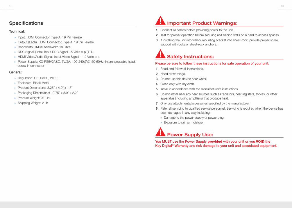
Specifications
Technical:
» Input: HDMI Connector, Type A, 19 Pin Female
» Output (Each): HDMI Connector, Type A, 19 Pin Female
» Bandwidth: TMDS bandwidth 18 Gb/s
» DDC Signal (Data): Input DDC Signal - 5 Volts p-p (TTL)
» HDMI Video/Audio Signal: Input Video Signal - 1.2 Volts p-p
» Power Supply: KD-PS5V2ASC, 5V/2A, 100-240VAC, 50-60Hz, Interchangeable head, screw-in connector
General:
» Regulation: CE, RoHS, WEEE
» Enclosure: Black Metal
» Product Dimensions: 8.25” x 4.0” x 1.7”
» Packaging Dimensions: 10.75” x 8.9” x 2.2”
» Product Weight: 0.9 lb
» Shipping Weight: 2 lb
Important Product Warnings:1. Connect all cables before providing power to the unit.
2. Test for proper operation before securing unit behind walls or in hard to access spaces.
3. If installing the unit into wall or mounting bracket into sheet-rock, provide proper screw support with bolts or sheet-rock anchors.
Safety Instructions:Please be sure to follow these instructions for safe operation of your unit.
1. Read and follow all instructions.
2. Heed all warnings.
3. Do not use this device near water.
4. Clean only with dry cloth.
5. Install in accordance with the manufacturer’s instructions.
6. Do not install near any heat sources such as radiators, heat registers, stoves, or other apparatus (including amplifiers) that produce heat.
7. Only use attachments/accessories specified by the manufacturer.
8. Refer all servicing to qualified service personnel. Servicing is required when the device has been damaged in any way including:
» Damage to the power supply or power plug
» Exposure to rain or moisture
Power Supply Use:You MUST use the Power Supply provided with your unit or you VOID the Key Digital® Warranty and risk damage to your unit and associated equipment.
KD-Pro2x1_4x1_Manual.indd 12-13 6/29/16 2:51 PM
14 15
How to Contact Key Digital®
System Design Group (SDG)
For system design questions please contact us at:
› Phone: 914-667-9700 › E-mail: [email protected]
Customer Support
For customer support questions please contact us at:
› Phone: 914-667-9700 › E-mail: [email protected]
Technical Support
For technical questions about using Key Digital® products, please contact us at:
› Phone: 914-667-9700 › E-mail: [email protected]
Repairs and Warranty Service
Should your product require warranty service or repair, please obtain a Key Digital® Return Material Authorization (RMA) number by contacting us at:
› Phone: 914-667-9700 › E-mail: [email protected]
Feedback
Please email any comments/questions about the manual to:
› E-mail: [email protected]
KD-Pro2x1_4x1_Manual.indd 14-15 6/29/16 2:51 PM

16 17
KD-Pro2x1_4x1_Manual.indd 16-17 6/29/16 2:51 PM


![KD-A645 / KD-R640 / KD-R540 / KD-R440 - Car Audio ...santafeautosound.com/uploads/product-manuals/JVC KD-R540.pdfKD-A645 / KD-R640 / KD-R540 / KD-R440 GET0829-001A [J/JW] ENGLISH ESPAÑOL](https://img.pdfslide.us/doc/110x75/5aaf5da87f8b9a25088d67c4/kd-a645-kd-r640-kd-r540-kd-r440-car-audio-kd-r540pdfkd-a645-kd-r640.jpg)