Embed Size (px)
Citation preview
Specialists in electronic kits, components and products. KC5324: TOUCH &/OR REMOTE CONTROLLED LIGHT DIMMER Silicon Chip Magazine January 2002 (p22 to p32) Silicon Chip Magazine February 2002 (p60 to p65) For Setup Procedure ONLY! Rev1 Batch No:
JAYCAR ELECTRONICS PTY LTD (ABN 65 000 087 936), 100 SILVERWATER RD, SILVERWATER, NSW 2128, AUSTRALIA Tel: (02) 9741 8555 Fax (02) 9741 8500 www.jaycar.com.au [email protected] 1 of 1
Sili
con
Chi
p M
agaz
ine
Jan
/ Feb
200
2
TOU
CH
&/O
R R
EM
OTE
C
ON
TR
OL
LE
D L
IGH
T
DIM
ME
R K
IT
Feat
ures
incl
ude
slim
line
appe
aran
ce, s
oft-
star
t to
exte
nd la
mp
life,
last
dim
set
ting
stor
ed, f
ull b
right
ness
on
seco
nd to
uch,
RF
I su
ppre
ssio
n an
d re
mot
e co
ntro
l
Opt
iona
l Rem
ote
Con
trol,
use
Ar1
703.
Ext
erna
l Com
pone
nts
for T
estin
g
PC
B, b
rush
ed a
lum
iniu
m to
uch
plat
e, P
IC m
icro
, cle
ar
IR w
indo
w a
nd a
ll el
ectr
onic
com
pone
nts.
KIT
RE
QU
IRE
S
KIT
INC
LUD
ES
CO
NS
TR
UC
TIO
N G
UID
E
( (( (
( (( (
( (( (
( (( (
( ( (( (
( (( (
( (( (
( ( (( (
( (( ( (
PLEASE READ BEFORE COMMENCING CONSTRUCTION The guarantee on this kit is limited to the replacement of faulty parts only, as we cannot guarantee the labour content you provide. "For Semiconductor Guarantee, see `Terms and Conditions' In our catalogue. Our Service Department does not do general service on simple kits and it is recommended that if a kit builder does not have enough knowledge to diagnose faults, that the project should not be started unless assistance can be obtained. Unfortunately, one small faulty solder joint or wiring mistake can take many hours to locate and at normal service rates the service charge could well be more than the total cost of the kit. If you believe that you may have difficulty in building this kit (which is simply a complete set of separate parts made up to a list provided by the major electronics magazines) and you cannot get assistance from a friend, we suggest you return the kit to us IN ITS ORIGINAL CONDITION for a refund under our satisfaction guarantee. Unfortunately, kits cannot be replaced under our satisfaction guarantee once construction has been commenced. CONTACTS: For functional or modification queries please contact Silicon Chip Publications who have designed and/or published this project: www.siliconchip.com.au [email protected] Silicon Chip Publications, POBox 139, Collaroy Beach, NSW 2097 For quality issues please contact the Production Manager at Jaycar Electronics and provide the following information: • Product Number • Batch No • Details of Quality Issue

Specialists in electronic kits, components and products. KC5324: TOUCH &/OR REMOTE CONTROLLED LIGHT DIMMER Silicon Chip Magazine January 2002 (p22 to p32) Silicon Chip Magazine February 2002 (p60 to p65) For Setup Procedure ONLY! Rev1
JAYCAR ELECTRONICS PTY LTD (ABN 65 000 087 936), 100 SILVERWATER RD, SILVERWATER, NSW 2128, AUSTRALIA Tel: (02) 9741 8555 Fax (02) 9741 8500 www.jaycar.com.au [email protected] 2 of 2
Notes and Errata (at time of print): It is recommended to check the designers/publishers website for further notes and errata since this document was issued, before starting construction. SC Jan 2002 (John Clarke): The thin track going to the extension terminal on the main pcb is designed as a fuse track to minimise damage and allow easier repair, in case an error is made connecting up the extension.
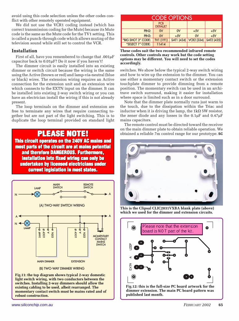
The Clipsal CLIC2031VXBA blank wall plate shown here assembled with the PC board. The two nylon PC board mounting screws are on the left and the metal screw is at the bottom (its head is above the plate surface to ensure contact with the aluminium cover plate). The infrared receiver is at the top, its hole covered by a piece of transparent sheet glued to the plastic.
marginally
Suggestion:1) Assemble PCB2) Drill 3 Screw Holes from Back of Plastic Plate3) Make Cardboard Template from PCB (for the 3 Screw Holes and the IR Receiver)4) Use Cardboard Template on Front of Plastic Plate to CAREFULLY drill IR Receiver Window5) Check that PCB and IR Window align6) Fit Aluminium Plate and CAREFULLY drill IR Window Hole
Sample Only!
Possible Substitutions Original Part Original Part Desc Subst Part Subst. Part Desc.
The following substitutes have been approved by Silicon Chip (Jan 2001) N/A FR102 (UF102, 1N4936) ZR1038 UF4007 1000V/1AMP ULTRAFAST
DIODE N/A SC141E Special Order BTA06-600T 6A600V
BTA08-600S 8A600V N/A Clear or Red Acrylic 15*20*0.5mm Polycarbonate
15*20*0.5mm Acrylic or Perspex (clear or transparent red) that is nominally 0.5-1mm thick. Alternatively, use polycarbonate sheeting which is around 1mm thick
N/A 1N4002 ZR14004 1N4004 1A 400V DIODE PKT 4
Specialists in electronic kits, components and products. KC5324: TOUCH &/OR REMOTE CONTROLLED LIGHT DIMMER Silicon Chip Magazine January 2002 (p22 to p32) Silicon Chip Magazine February 2002 (p60 to p65) For Setup Procedure ONLY! Rev1
JAYCAR ELECTRONICS PTY LTD (ABN 65 000 087 936), 100 SILVERWATER RD, SILVERWATER, NSW 2128, AUSTRALIA Tel: (02) 9741 8555 Fax (02) 9741 8500 www.jaycar.com.au [email protected] 3 of 3
PARTS LIST * Please note that quantities listed refer to the actual number of items required. When purchasing individual items separately, take pack quantities into account. 1 See section about Substitution 2 See section about Notes & Errata 3 Processed Panel not part of Case listed
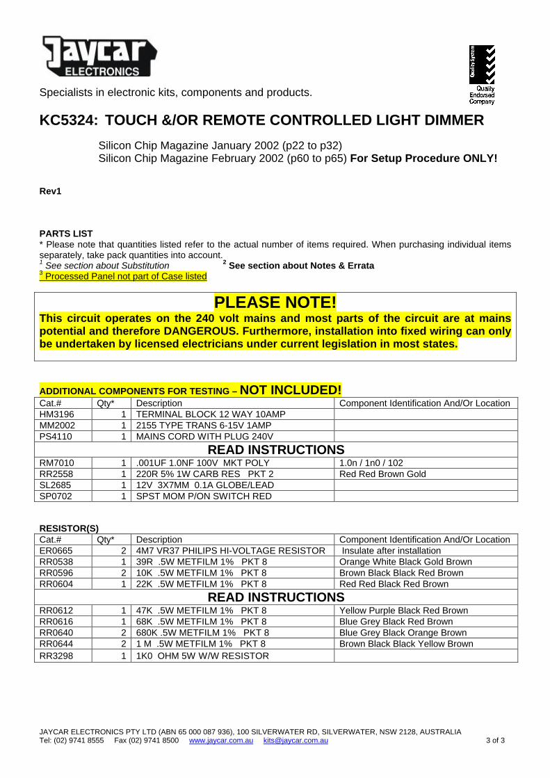
PLEASE NOTE! This circuit operates on the 240 volt mains and most parts of the circuit are at mains potential and therefore DANGEROUS. Furthermore, installation into fixed wiring can only be undertaken by licensed electricians under current legislation in most states.
ADDITIONAL COMPONENTS FOR TESTING – NOT INCLUDED! Cat.# Qty* Description Component Identification And/Or Location HM3196 1 TERMINAL BLOCK 12 WAY 10AMP MM2002 1 2155 TYPE TRANS 6-15V 1AMP PS4110 1 MAINS CORD WITH PLUG 240V
READ INSTRUCTIONS RM7010 1 .001UF 1.0NF 100V MKT POLY 1.0n / 1n0 / 102 RR2558 1 220R 5% 1W CARB RES PKT 2 Red Red Brown Gold SL2685 1 12V 3X7MM 0.1A GLOBE/LEAD SP0702 1 SPST MOM P/ON SWITCH RED RESISTOR(S) Cat.# Qty* Description Component Identification And/Or Location ER0665 2 4M7 VR37 PHILIPS HI-VOLTAGE RESISTOR Insulate after installation RR0538 1 39R .5W METFILM 1% PKT 8 Orange White Black Gold Brown RR0596 2 10K .5W METFILM 1% PKT 8 Brown Black Black Red Brown RR0604 1 22K .5W METFILM 1% PKT 8 Red Red Black Red Brown
READ INSTRUCTIONS RR0612 1 47K .5W METFILM 1% PKT 8 Yellow Purple Black Red Brown RR0616 1 68K .5W METFILM 1% PKT 8 Blue Grey Black Red Brown RR0640 2 680K .5W METFILM 1% PKT 8 Blue Grey Black Orange Brown RR0644 2 1 M .5W METFILM 1% PKT 8 Brown Black Black Yellow Brown RR3298 1 1K0 OHM 5W W/W RESISTOR
Specialists in electronic kits, components and products. KC5324: TOUCH &/OR REMOTE CONTROLLED LIGHT DIMMER Silicon Chip Magazine January 2002 (p22 to p32) Silicon Chip Magazine February 2002 (p60 to p65) For Setup Procedure ONLY! Rev1
JAYCAR ELECTRONICS PTY LTD (ABN 65 000 087 936), 100 SILVERWATER RD, SILVERWATER, NSW 2128, AUSTRALIA Tel: (02) 9741 8555 Fax (02) 9741 8500 www.jaycar.com.au [email protected] 4 of 4
CAPACITOR(S) Cat.# Qty* Description Component Identification And/Or Location RC5316 2 22PF CERAM. 50V CAP PKT 2 22pF RC5360 1 .1UF CERAM. 50V CAP PKT 2 0.1uF / u1 / 100n / 104 RE6194 1 470U/16VRB ELECT CAPACITOR 470uF / 16V
READ INSTRUCTIONS RG5254 1 0.1UF 250V AC MAINS CAP 0.1uF / u1 / 100n / 104 (250V) RG5257 1 0.47UF 250V AC MAINS CAP 0.47uF / u47 / 470n / 474 (250V) RM7065 1 .01UF 10NF 100V MKT POLY 0.01uF / 10n / 103 RZ6670 1 47UF 16V TAG TANT 47UTT16 SEMICONDUCTOR(S) Cat.# Qty* Description Component Identification And/Or Location PI6503 1 18 PIN IC SOCKET PCB TIN/G RQ5289 1 10.000 MHZ XTAL(P)HC-18(K) 10.000MHz ZD1952 1 IR LED RECEIVER IC2 ZR1032 1 UF4002 100V/1AMP ULTRAFAST DIODE UF4002 D1
READ INSTRUCTIONS ZT2110 1 BC327 PNP 45V500MA SIG TO92 BC327 Q1
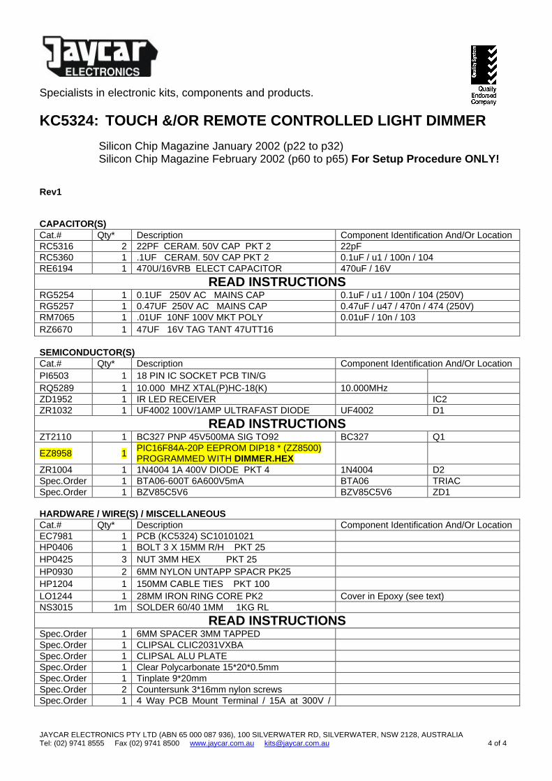
EZ8958 1 PIC16F84A-20P EEPROM DIP18 * (ZZ8500) PROGRAMMED WITH DIMMER.HEX
ZR1004 1 1N4004 1A 400V DIODE PKT 4 1N4004 D2 Spec.Order 1 BTA06-600T 6A600V5mA BTA06 TRIAC Spec.Order 1 BZV85C5V6 BZV85C5V6 ZD1 HARDWARE / WIRE(S) / MISCELLANEOUS Cat.# Qty* Description Component Identification And/Or Location EC7981 1 PCB (KC5324) SC10101021 HP0406 1 BOLT 3 X 15MM R/H PKT 25 HP0425 3 NUT 3MM HEX PKT 25 HP0930 2 6MM NYLON UNTAPP SPACR PK25 HP1204 1 150MM CABLE TIES PKT 100 LO1244 1 28MM IRON RING CORE PK2 Cover in Epoxy (see text) NS3015 1m SOLDER 60/40 1MM 1KG RL
READ INSTRUCTIONS Spec.Order 1 6MM SPACER 3MM TAPPED Spec.Order 1 CLIPSAL CLIC2031VXBA Spec.Order 1 CLIPSAL ALU PLATE Spec.Order 1 Clear Polycarbonate 15*20*0.5mm Spec.Order 1 Tinplate 9*20mm Spec.Order 2 Countersunk 3*16mm nylon screws Spec.Order 1 4 Way PCB Mount Terminal / 15A at 300V /

Specialists in electronic kits, components and products. KC5324: TOUCH &/OR REMOTE CONTROLLED LIGHT DIMMER Silicon Chip Magazine January 2002 (p22 to p32) Silicon Chip Magazine February 2002 (p60 to p65) For Setup Procedure ONLY! Rev1
JAYCAR ELECTRONICS PTY LTD (ABN 65 000 087 936), 100 SILVERWATER RD, SILVERWATER, NSW 2128, AUSTRALIA Tel: (02) 9741 8555 Fax (02) 9741 8500 www.jaycar.com.au [email protected] 5 of 5
8.25mm Pitch WS5502 5cm 1.5mm spagetti tubing WW4018 1.5m .63MM EN CU WIRE 22BS 100G
PLEASE NOTE! This circuit operates on the 240 volt mains and most parts of the circuit are at mains potential and therefore DANGEROUS. Furthermore, installation into fixed wiring can only be undertaken by licensed electricians under current legislation in most states.

22 SILICON CHIP www.siliconchip.com.au
( ( ( ( ( ( ( ( ( ( ( ( ( ( ( ( ( ( ( ( ( ( ( ( ( ( ( ( ( ( ( ( ( ( ( ( ( ( (
TOUCH and/orREMOTE-CONTROLLEDLIGHTDIMMER
Old-fashioned light dimmers with their knobs on the architraveare so passé! Here’s one that you simply touch to dim up or down,or touch again to turn full on or full off. Not decadent enough?How about full remote control from the comfort of your armchair?Now that’s a dimmer!
Every now and then we get aletter or email criticising ouruse of a microcontroller when
(perhaps) a similar job could have beendone with (lots of!) discrete compo-nents.
Well, look at our latest light dim-mer – and what it does. We make noapologies for using a PIC because itdoes so much, so simply. A projectsuch as this demonstrates perfectlywhy we use microcontrollers.
There would be very few homesthat don’t have a light dimmer or three.So-called “mood lighting” became thebig thing in the eighties; today light
dimmers are installed in living rooms,lounge rooms, bedrooms – in fact, justabout anywhere.
But the traditional wall-mounted,knob-controlled light dimmer has amajor drawback. You decide you wantto dim the lights and you have to getup out of your comfy chair and go anddo it. Wouldn’t it be nice if you coulddo it by remote control?
You can with the all-new SILICONCHIP light dimmer. What’s more,there’s no ugly knob. There’s not evena light switch!
As well as using a remote control,you can actuate the dimmer – up or
down – by simply touching an attrac-tive plate which takes the place of thelight switch and knob. And you canadd one or more extensions for two,three or more-way dimming.
The dimmer itself is very sleek. Theonly part that you see when mountedonto a wall is a modern aluminiumwallplate (we used a commercially-available Clipsal Classic 2000 blankplate – so it looks very professionaland as modern as tomorrow.
A "window" is added to allow forreception of the remote control infra-red transmission from the hand-heldunit.
By John Clarke
TOUCH and/orREMOTE-CONTROLLEDLIGHTDIMMER
22 SILICON CHIP www.siliconchip.com.au
www.siliconchip.com.au JANUARY 2002 23
( ( ( ( ( ( ( ( ( ( ( ( ( ( ( ( ( ( ( ( ( ( ( ( ( ( ( ( ( ( ( ( ( ( ( ( ( ( ( ( ( ( ( ( ( ( ( ( ( ( ( ( ( ( ( ( ( ( ( ( ( ( ( ( ( ( ( ( ( ( ( ( ( ( ( ( ( ( ( ( ( ( ( ( ( ( ( ( ( ( ( ( (
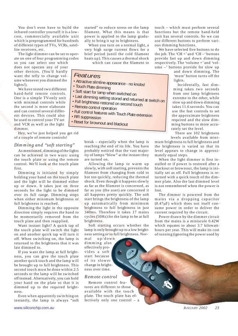
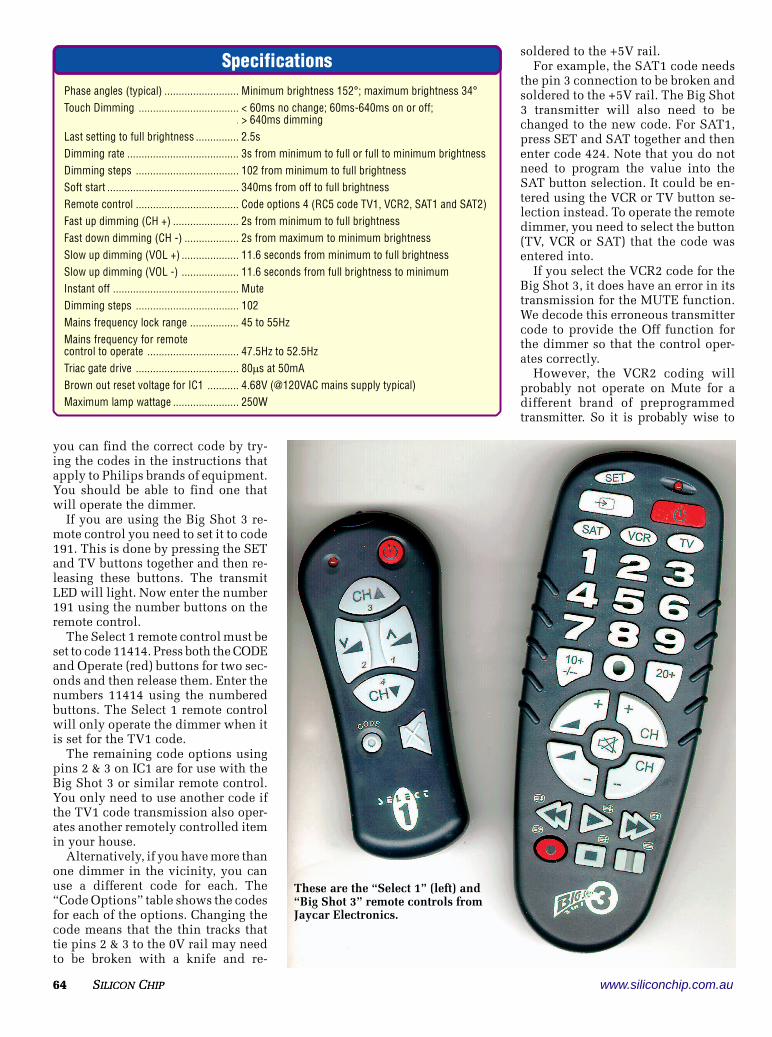
You don’t even have to build theinfrared controller yourself: it is a low-cost, commercially available unitwhich is preprogrammed for hundredsof different types of TVs, VCRs, satel-lite receivers, etc.
The light dimmer can be set to oper-ate on one of four programming codesso you can select one whichdoes not operate any of yourother devices. (You’d hardlywant the telly to change vol-ume whenever you dimmed thelights!).
We have tested two differenthand-held remote controls.One is a simple TV-only unitwith minimal controls whilethe second is more elaborateand can control several differ-ent devices. This could alsobe used to control your TV setand VCR as well as the lightdimmer.
Hey, we’ve just helped you get ridof a couple of remote controls!
Dimming and “soft starting”As mentioned, dimming of the lights
can be achieved in two ways: usingthe touch plate or using the remotecontrol. We’ll look at the touch platefirst.
Dimming is initiated by simplyholding your hand on the touch plateand the light will be dimmed eitherup or down. It takes just on threeseconds for the light to be dimmedover its full range. Dimming stopswhen either minimum brightness orfull brightness is reached.
Dimming the light in the oppositedirection simply requires the hand tobe momentarily removed from thetouch plate and then reapplied.
Want instant light? A quick tap ofthe touch plate will switch the lighton and another quick tap will turn itoff. When switching on, the lamp isreturned to the brightness that it waslast dimmed to.
If you want the lamp at full bright-ness, you can give the touch plateanother quick touch and the lamp willbe brought up to full brightness. Thissecond touch must be done within 2.5seconds or the lamp will be switchedoff instead. Alternatively, you can holdyour hand on the plate so that it isdimmed up to the required bright-ness.
Even when apparently switching oninstantly, the lamp is always “soft
started” to reduce stress on the lampfilament. What this means is thatpower is applied to the lamp gradu-ally to bring it up to brightness.
When you turn on a normal light, avery high surge current flows for abrief period (until the cold filamentheats up). This causes a thermal shock
which can cause the filament to
break – especially when the lamp isreaching the end of its life. You haveprobably noticed that the vast major-ity of lamps “blow” at the instant theyare turned on.
Allowing the lamp to warm upslowly, with soft starting, prevents thefilament from changing from cold tohot too quickly, reducing the thermalshock. Even though it happens slowlyas far as the filament is concerned, asfar as you (the user) are concerned itall happens pretty quickly. The softstart brings the brightness of the lampup automatically from minimumbrightness to full brightness in just340ms. Therefore it takes 17 mainscycles (50Hz) for the lamp to be at fullbrightness.
Soft starting occurs whether thelamp is only brought up to a low bright-ness setting or to full brightness. Nor-mal up/downdimming alsoeffectively pro-vides a softstart becauseof its slowerchange in bright-ness over time.
Remote controlRemote control fea-
tures are different to thoseavailable with the touchplate. The touch plate has ef-fectively only one control – a
touch – which must perform severalfunctions but the remote hand-heldunit has several controls. So we canuse different buttons to perform vari-ous dimming functions.
We have selected five buttons to dothe job. The ‘CH +’ and ‘CH –‘ buttonsprovide fast up and down dimmingrespectively. The ‘volume +’ and ‘vol-ume –’ buttons provide for slow up
and down dimming. The‘mute’ button turns off thelights.
Incidentally, fast dim-ming takes two secondsfrom one lamp brightnessextreme to the other, whileslow up and down dimmingtakes 11.6 seconds. You canuse the fast controls to setthe approximate brightnessrequired and the slow dim-ming buttons to more accu-rately set the level.
There are 102 brightnesslevels available from mini-
mum brightness to full brightness andthe brightness is varied so that itslevel appears to change in approxi-mately equal steps.
When the light dimmer is first in-stalled or if power is restored after ablackout or brownout, the lamp is ini-tially set as off. Full brightness is re-turned with a quick touch of the dim-mer plate. Also the last dimmed levelis not remembered when the power islost.
The dimmer is powered from themains via a dropping capacitor(0.47�F) which does not itself con-sume power in order to deliver thecurrent required by the circuit.
Power drawn by the dimmer circuitfrom the mains is a miniscule 0.42Wwhich equates to about 3.7 kilowatt-hours per year. This will make its costof running (ignoring the power used by
Features• Attractive slimline appearance - no knobs!• Touch Plate dimming• Soft start for lamp when switched on• Last dimming setting stored and returned at switch on• Full brightness restored on second touch• Remote control operation• Full control features with Touch Plate extension• RFI suppression• Reset for brownout and blackout
24 SILICON CHIP www.siliconchip.com.au
tain portions of the mains cycle. Ifpower is connected early in the cycle,the lamp will glow brighter. But if it isconnected much later in the cycle, thelamp will glow much dimmer, simplybecause there isn’t the power to heatthe filament as much.
Switching is performed by a deviceknown as a Triac which can be trig-gered on by a voltage at its gate. TheTriac will only turn off when currentthrough it drops below a certainthreshold value. In practice, whendriving a resistive load, this meansthat the Triac switches off when themains voltage is near 0V. The accom-
panying oscilloscope traces show howit works.
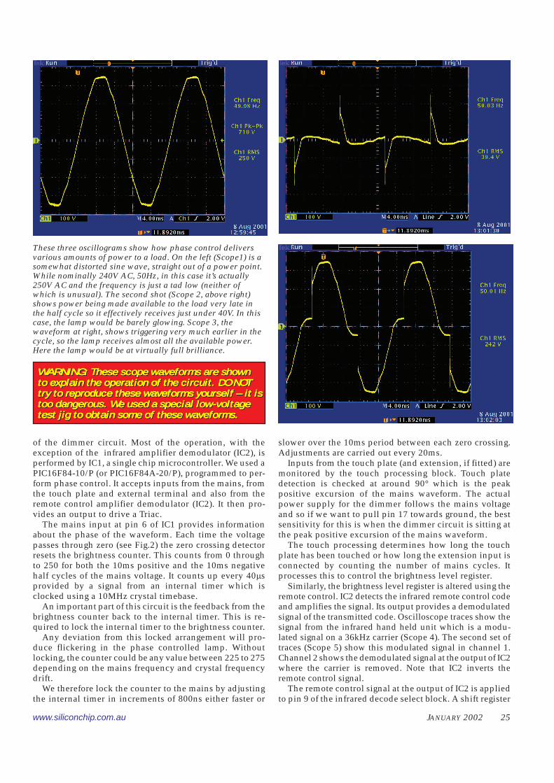
The first oscilloscope waveform(Scope 1) is the 50Hz mains sinusuoi-dal voltage measured on the activeoutput of a power point. This has aneffective or RMS voltage of 240V (±5%)while the peak voltage is about 339V.Note that the mains voltage shownhere is higher – 250VAC and 355Vpeak (half the peak-to-peak voltage).
The second oscilloscope screen(Scope 2) shows the waveform ap-plied to the lamp when it is requiredto have a low brightness. In this case,the lamp is powered about 150° fromthe start of each mains half cycle andis switched off at 0V. The lamp volt-age is applied for both positive andnegative excursions of the mains andthe RMS voltage is around 39V.
The next oscilloscope waveform(Scope 3) show the lamp voltage whenit is bright. Now the voltage is appliedearly in each mains half cycle so thatalmost the full mains waveform is ap-plied. Again the lamp is switched offat 0V. The RMS voltage is now a lothigher at 242V.
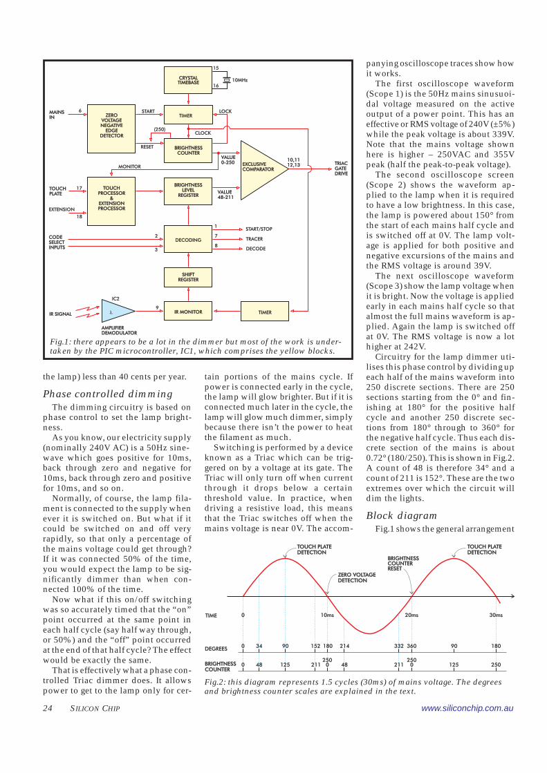
Circuitry for the lamp dimmer uti-lises this phase control by dividing upeach half of the mains waveform into250 discrete sections. There are 250sections starting from the 0° and fin-ishing at 180° for the positive halfcycle and another 250 discrete sec-tions from 180° through to 360° forthe negative half cycle. Thus each dis-crete section of the mains is about0.72° (180/250). This is shown in Fig.2.A count of 48 is therefore 34° and acount of 211 is 152°. These are the twoextremes over which the circuit willdim the lights.
Block diagramFig.1 shows the general arrangement
the lamp) less than 40 cents per year.
Phase controlled dimmingThe dimming circuitry is based on
phase control to set the lamp bright-ness.
As you know, our electricity supply(nominally 240V AC) is a 50Hz sine-wave which goes positive for 10ms,back through zero and negative for10ms, back through zero and positivefor 10ms, and so on.
Normally, of course, the lamp fila-ment is connected to the supply whenever it is switched on. But what if itcould be switched on and off veryrapidly, so that only a percentage ofthe mains voltage could get through?If it was connected 50% of the time,you would expect the lamp to be sig-nificantly dimmer than when con-nected 100% of the time.
Now what if this on/off switchingwas so accurately timed that the “on”point occurred at the same point ineach half cycle (say half way through,or 50%) and the “off” point occurredat the end of that half cycle? The effectwould be exactly the same.
That is effectively what a phase con-trolled Triac dimmer does. It allowspower to get to the lamp only for cer-
CRYSTALTIMEBASECRYSTALTIMEBASE
TIMER
BRIGHTNESSCOUNTER
BRIGHTNESSCOUNTER
BRIGHTNESSLEVEL
REGISTER
BRIGHTNESSLEVEL
REGISTER
DECODING
SHIFTREGISTER
SHIFTREGISTER
IR MONITORIR MONITOR TIMER
ZEROVOLTAGENEGATIVE
EDGEDETECTOR
ZEROVOLTAGENEGATIVE
EDGEDETECTOR
TOUCHPROCESSOR
&EXTENSIONPROCESSOR
TOUCHPROCESSOR
&EXTENSIONPROCESSOR
�
AMPLIFIERDEMODULATORAMPLIFIERDEMODULATOR
15
16
LOCKSTART
RESET
CLOCK
VALUE0-250VALUE0-250
10,1112,1310,1112,13 TRIAC
GATEDRIVE
TRIACGATEDRIVE
EXCLUSIVECOMPARATOREXCLUSIVECOMPARATOR
VALUE48-211VALUE48-211
1
7
8
START/STOP
TRACER
DECODE
9
2
3
IC2
IR SIGNALIR SIGNAL
17
18
6MAINSINMAINSIN
TOUCHPLATETOUCHPLATE
EXTENSION
CODESELECTINPUTS
CODESELECTINPUTS
(250)
10MHz
MONITOR
Fig.1: there appears to be a lot in the dimmer but most of the work is under-taken by the PIC microcontroller, IC1, which comprises the yellow blocks.
TIME
DEGREES
BRIGHTNESSCOUNTERBRIGHTNESSCOUNTER
0
0
34 90 152 180 214 332 360 18090
48 125 211250
48 211 0250
125 2500
0 10ms 20ms 30ms
TOUCH PLATEDETECTIONTOUCH PLATEDETECTION
TOUCH PLATEDETECTIONTOUCH PLATEDETECTION
ZERO VOLTAGEDETECTIONZERO VOLTAGEDETECTION
BRIGHTNESSCOUNTERRESET
BRIGHTNESSCOUNTERRESET
Fig.2: this diagram represents 1.5 cycles (30ms) of mains voltage. The degreesand brightness counter scales are explained in the text.
www.siliconchip.com.au JANUARY 2002 25
of the dimmer circuit. Most of the operation, with theexception of the infrared amplifier demodulator (IC2), isperformed by IC1, a single chip microcontroller. We used aPIC16F84-10/P (or PIC16F84A-20/P), programmed to per-form phase control. It accepts inputs from the mains, fromthe touch plate and external terminal and also from theremote control amplifier demodulator (IC2). It then pro-vides an output to drive a Triac.
The mains input at pin 6 of IC1 provides informationabout the phase of the waveform. Each time the voltagepasses through zero (see Fig.2) the zero crossing detectorresets the brightness counter. This counts from 0 throughto 250 for both the 10ms positive and the 10ms negativehalf cycles of the mains voltage. It counts up every 40�sprovided by a signal from an internal timer which isclocked using a 10MHz crystal timebase.
An important part of this circuit is the feedback from thebrightness counter back to the internal timer. This is re-quired to lock the internal timer to the brightness counter.
Any deviation from this locked arrangement will pro-duce flickering in the phase controlled lamp. Withoutlocking, the counter could be any value between 225 to 275depending on the mains frequency and crystal frequencydrift.
We therefore lock the counter to the mains by adjustingthe internal timer in increments of 800ns either faster or
slower over the 10ms period between each zero crossing.Adjustments are carried out every 20ms.
Inputs from the touch plate (and extension, if fitted) aremonitored by the touch processing block. Touch platedetection is checked at around 90° which is the peakpositive excursion of the mains waveform. The actualpower supply for the dimmer follows the mains voltageand so if we want to pull pin 17 towards ground, the bestsensitivity for this is when the dimmer circuit is sitting atthe peak positive excursion of the mains waveform.
The touch processing determines how long the touchplate has been touched or how long the extension input isconnected by counting the number of mains cycles. Itprocesses this to control the brightness level register.
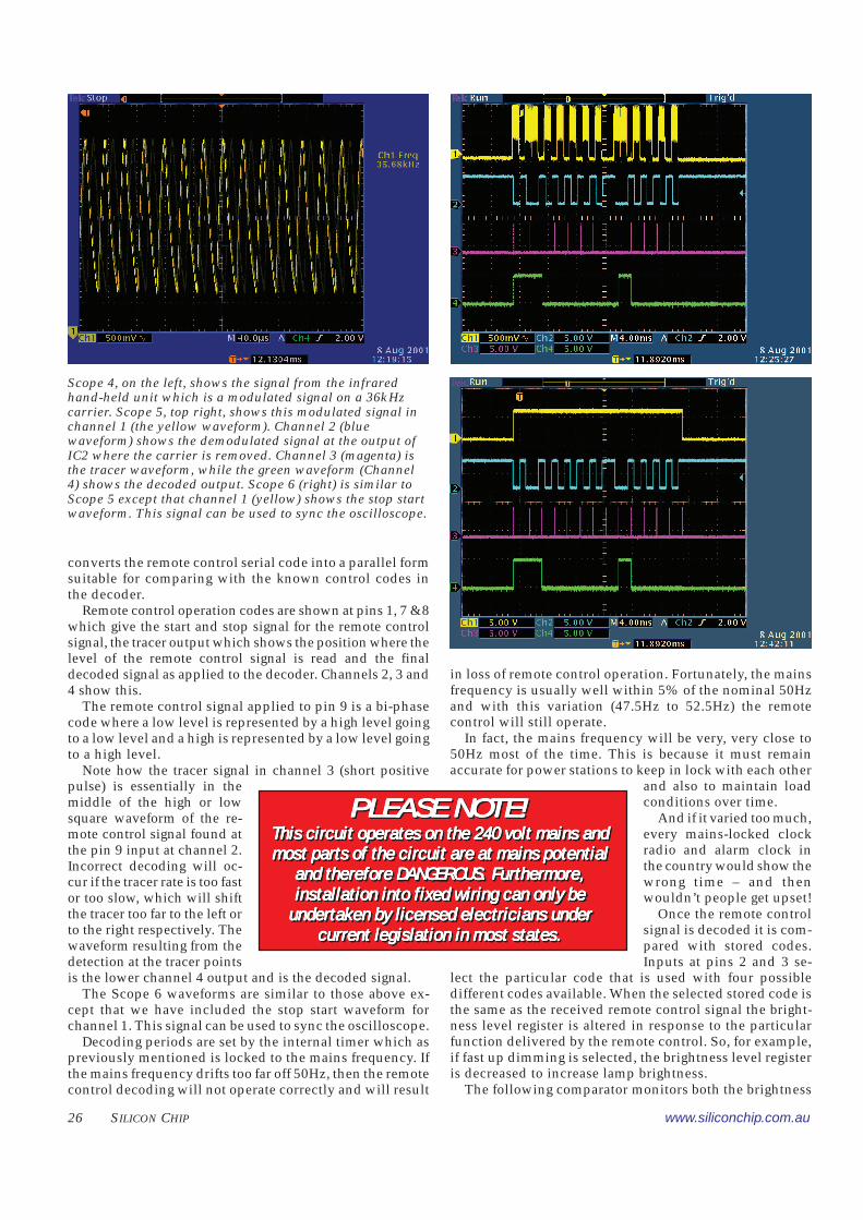
Similarly, the brightness level register is altered using theremote control. IC2 detects the infrared remote control codeand amplifies the signal. Its output provides a demodulatedsignal of the transmitted code. Oscilloscope traces show thesignal from the infrared hand held unit which is a modu-lated signal on a 36kHz carrier (Scope 4). The second set oftraces (Scope 5) show this modulated signal in channel 1.Channel 2 shows the demodulated signal at the output of IC2where the carrier is removed. Note that IC2 inverts theremote control signal.
The remote control signal at the output of IC2 is appliedto pin 9 of the infrared decode select block. A shift register
These three oscillograms show how phase control deliversvarious amounts of power to a load. On the left (Scope1) is asomewhat distorted sine wave, straight out of a power point.While nominally 240V AC, 50Hz, in this case it’s actually250V AC and the frequency is just a tad low (neither ofwhich is unusual). The second shot (Scope 2, above right)shows power being made available to the load very late inthe half cycle so it effectively receives just under 40V. In thiscase, the lamp would be barely glowing. Scope 3, thewaveform at right, shows triggering very much earlier in thecycle, so the lamp receives almost all the available power.Here the lamp would be at virtually full brilliance.
WWWWWARNING: ARNING: ARNING: ARNING: ARNING: These scope waveforThese scope waveforThese scope waveforThese scope waveforThese scope waveforms arms arms arms arms are showne showne showne showne shownto explain the operation of the circuit. DO NOTto explain the operation of the circuit. DO NOTto explain the operation of the circuit. DO NOTto explain the operation of the circuit. DO NOTto explain the operation of the circuit. DO NOTtrtrtrtrtry to ry to ry to ry to ry to reprepreprepreproduce these waveforoduce these waveforoduce these waveforoduce these waveforoduce these waveforms yourself – it isms yourself – it isms yourself – it isms yourself – it isms yourself – it istoo dangertoo dangertoo dangertoo dangertoo dangerous. Wous. Wous. Wous. Wous. We used a special low-voltagee used a special low-voltagee used a special low-voltagee used a special low-voltagee used a special low-voltagetest jig to obtain some of these waveforms.test jig to obtain some of these waveforms.test jig to obtain some of these waveforms.test jig to obtain some of these waveforms.test jig to obtain some of these waveforms.
WWWWWARNING: ARNING: ARNING: ARNING: ARNING: These scope waveforThese scope waveforThese scope waveforThese scope waveforThese scope waveforms arms arms arms arms are showne showne showne showne shownto explain the operation of the circuit. DO NOTto explain the operation of the circuit. DO NOTto explain the operation of the circuit. DO NOTto explain the operation of the circuit. DO NOTto explain the operation of the circuit. DO NOTtrtrtrtrtry to ry to ry to ry to ry to reprepreprepreproduce these waveforoduce these waveforoduce these waveforoduce these waveforoduce these waveforms yourself – it isms yourself – it isms yourself – it isms yourself – it isms yourself – it istoo dangertoo dangertoo dangertoo dangertoo dangerous. Wous. Wous. Wous. Wous. We used a special low-voltagee used a special low-voltagee used a special low-voltagee used a special low-voltagee used a special low-voltagetest jig to obtain some of these waveforms.test jig to obtain some of these waveforms.test jig to obtain some of these waveforms.test jig to obtain some of these waveforms.test jig to obtain some of these waveforms.
26 SILICON CHIP www.siliconchip.com.au
converts the remote control serial code into a parallel formsuitable for comparing with the known control codes inthe decoder.
Remote control operation codes are shown at pins 1, 7 & 8which give the start and stop signal for the remote controlsignal, the tracer output which shows the position where thelevel of the remote control signal is read and the finaldecoded signal as applied to the decoder. Channels 2, 3 and4 show this.
The remote control signal applied to pin 9 is a bi-phasecode where a low level is represented by a high level goingto a low level and a high is represented by a low level goingto a high level.
Note how the tracer signal in channel 3 (short positivepulse) is essentially in themiddle of the high or lowsquare waveform of the re-mote control signal found atthe pin 9 input at channel 2.Incorrect decoding will oc-cur if the tracer rate is too fastor too slow, which will shiftthe tracer too far to the left orto the right respectively. Thewaveform resulting from thedetection at the tracer pointsis the lower channel 4 output and is the decoded signal.
The Scope 6 waveforms are similar to those above ex-cept that we have included the stop start waveform forchannel 1. This signal can be used to sync the oscilloscope.
Decoding periods are set by the internal timer which aspreviously mentioned is locked to the mains frequency. Ifthe mains frequency drifts too far off 50Hz, then the remotecontrol decoding will not operate correctly and will result
in loss of remote control operation. Fortunately, the mainsfrequency is usually well within 5% of the nominal 50Hzand with this variation (47.5Hz to 52.5Hz) the remotecontrol will still operate.
In fact, the mains frequency will be very, very close to50Hz most of the time. This is because it must remainaccurate for power stations to keep in lock with each other
and also to maintain loadconditions over time.
And if it varied too much,every mains-locked clockradio and alarm clock inthe country would show thewrong time – and thenwouldn’t people get upset!
Once the remote controlsignal is decoded it is com-pared with stored codes.Inputs at pins 2 and 3 se-
lect the particular code that is used with four possibledifferent codes available. When the selected stored code isthe same as the received remote control signal the bright-ness level register is altered in response to the particularfunction delivered by the remote control. So, for example,if fast up dimming is selected, the brightness level registeris decreased to increase lamp brightness.
The following comparator monitors both the brightness
Scope 4, on the left, shows the signal from the infraredhand-held unit which is a modulated signal on a 36kHzcarrier. Scope 5, top right, shows this modulated signal inchannel 1 (the yellow waveform). Channel 2 (bluewaveform) shows the demodulated signal at the output ofIC2 where the carrier is removed. Channel 3 (magenta) isthe tracer waveform, while the green waveform (Channel4) shows the decoded output. Scope 6 (right) is similar toScope 5 except that channel 1 (yellow) shows the stop startwaveform. This signal can be used to sync the oscilloscope.
PLEASE NOTE!PLEASE NOTE!PLEASE NOTE!PLEASE NOTE!PLEASE NOTE!This circuit operates on the 240 volt mains andThis circuit operates on the 240 volt mains andThis circuit operates on the 240 volt mains andThis circuit operates on the 240 volt mains andThis circuit operates on the 240 volt mains andmost parts of the circuit are at mains potentialmost parts of the circuit are at mains potentialmost parts of the circuit are at mains potentialmost parts of the circuit are at mains potentialmost parts of the circuit are at mains potential
and therefore DANGEROUS. Furthermore,and therefore DANGEROUS. Furthermore,and therefore DANGEROUS. Furthermore,and therefore DANGEROUS. Furthermore,and therefore DANGEROUS. Furthermore,installation into fixed wiring can only beinstallation into fixed wiring can only beinstallation into fixed wiring can only beinstallation into fixed wiring can only beinstallation into fixed wiring can only be
undertaken by licensed electricians underundertaken by licensed electricians underundertaken by licensed electricians underundertaken by licensed electricians underundertaken by licensed electricians undercurrent legislation in most states.current legislation in most states.current legislation in most states.current legislation in most states.current legislation in most states.
www.siliconchip.com.au JANUARY 2002 27
level register and the brightness coun-ter. When they are equal, the compa-rator output provides a pulse to drivethe Triac gate.
If the brightness level register is alow value, this value will be equal tothe brightness counter early in themains cycle to provide a bright lamp.If the brightness level register is alarger value, the value will be equal tothe brightness counter later in themains cycle and so the lamp will bedimmer.
The circuitConsidering the complexity of the
dimmer operation, there is not toomuch in the actual circuit itself. Thisis because most of the work is done inthe PIC16F84-10P microcontroller(IC1). Apart from this IC there is only
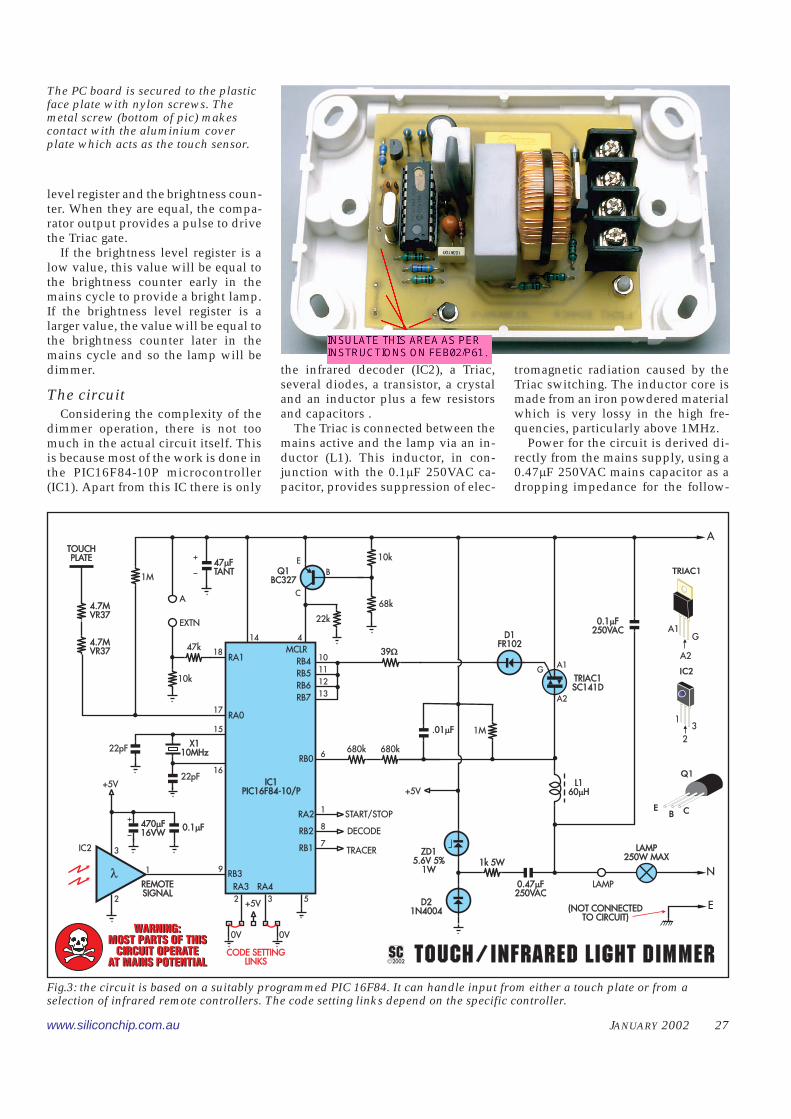
the infrared decoder (IC2), a Triac,several diodes, a transistor, a crystaland an inductor plus a few resistorsand capacitors .
The Triac is connected between themains active and the lamp via an in-ductor (L1). This inductor, in con-junction with the 0.1�F 250VAC ca-pacitor, provides suppression of elec-
tromagnetic radiation caused by theTriac switching. The inductor core ismade from an iron powdered materialwhich is very lossy in the high fre-quencies, particularly above 1MHz.
Power for the circuit is derived di-rectly from the mains supply, using a0.47�F 250VAC mains capacitor as adropping impedance for the follow-
TOUCHPLATE
TOUCHPLATE
4.7MVR374.7MVR37
4.7MVR374.7MVR37
1M
47k
10k
A
EXTN
18
14 4
47 FTANT
�47 FTANT
�10k
68k
22k
Q1BC327
Q1BC327
EB
C
+5V
10
11
12
13
39�39�RB4RB5RB6RB7
17
22pF
22pF
X110MHz
X110MHz
15
16
+5V
9
IC1PIC16F84-10/P
IC1PIC16F84-10/P
RB3
RA0
RA1MCLR
�
IC2
REMOTESIGNALREMOTESIGNAL
1
3
2
0.1 F�0.1 F�470 F16VW
�470 F16VW
�
1M.01 F�.01 F�
L160 H�
L160 H�
START/STOP
DECODE
TRACER
6
1
8
7
RB0
RA2
RB2
RB1
D1FR102
D1FR102
TRIAC1SC141DTRIAC1SC141D
GA1
A2
0.1 F250VAC
�0.1 F250VAC
�
0.47 F250VAC
�0.47 F250VAC
�
1k 5W1k 5WZD1
5.6V 5%1W
ZD15.6V 5%
1W
D21N4004
D21N4004
LAMP250W MAX
LAMP250W MAX
LAMPN
E(NOT CONNECTEDTO CIRCUIT)
(NOT CONNECTEDTO CIRCUIT)
5+5V
RA3 RA432
0V 0V
2002SC� TOUCH/INFRARED LIGHT DIMMERTOUCH/INFRARED LIGHT DIMMERCODE SETTING
LINKSCODE SETTING
LINKS
680k 680k
A
A2
A1G
TRIAC1
1
2
3
IC2
Q1
EB C
WARNING:MOST PARTS OF THIS
CIRCUIT OPERATEAT MAINS POTENTIAL
WARNING:MOST PARTS OF THIS
CIRCUIT OPERATEAT MAINS POTENTIAL
Fig.3: the circuit is based on a suitably programmed PIC 16F84. It can handle input from either a touch plate or from aselection of infrared remote controllers. The code setting links depend on the specific controller.
The PC board is secured to the plasticface plate with nylon screws. Themetal screw (bottom of pic) makescontact with the aluminium coverplate which acts as the touch sensor.
28 SILICON CHIP www.siliconchip.com.au
ing 5.6V zener diode, ZD1. The 0.47�Fcapacitor has an impedance of 6.77k�at 50Hz. When combined with theseries 1k� resistor this doesn’t give aneffective impedance of 7.77k���as youmight expect. It’s actually 6.84k��dueto the phase differences between thecapacitor and the resistor. This im-pedance limits the current flow inZD1 to 35mA.
The resulting supply is about 5Vdue to the voltage drop across D2.
One thing to note here is that this5V power supply can only be obtainedwhen the Triac is off. When the Triacis on there is only about 1V across itwhich is insufficient to develop thepower supply voltage.
Thus the phase control is limited toa minimum of 35° to make sure thatthere will always be power available.This phase angle also sets the maxi-
mum brightness for the lamp. While itappears to be fully bright, it is notquite as bright as if switched directlyacross the mains supply.
If the 0.47�F capacitor gives an im-pedance of 6.77k� by itself, why in-clude the 1k� resistor in series? Onereason is to limit surge currents if themains supply is connected during thepeak of the supply. However, there isanother and more important reasonand is because of the Triac.
When the Triac is fired, the chargeon the capacitor is immediately dis-charged through L1, the Triac, thezener diode and the 1k� resistor. Sowe need to limit this surge currentthrough the zener diode, particularlywhen the capacitor is charged to 340V(the peak of the 240V AC waveform).
Dissipation in the 1k� resistor isanother consideration. If the Triac is
off, then the 0.47�F capaci-tor can charge and dischargesmoothly with the sine wavevoltage and the currentthrough the 1k� resistor isabout 35mA RMS. This givesa power dissipation in the1k� resistor of 1.23W.
Things are different whenthe Triac is fired. This is be-cause of the energy stored inthe capacitor – 27mJ (½ CV2).To convert this to watts wemultiply by 100 as there arethis many half cycles in a50Hz mains waveform persecond. The worst case dis-sipation then becomes 2.7Win the 1k� resistor.
Selection of the resistancevalue is a compromise be-tween having low power dis-sipation when the Triac is off(which calls for a low valueof resistance) and reducing
the surge current through the zenerdiode when the Triac is fired (whichcalls for a large value of resistance).
The resulting DC supply is filteredwith the 470�F electrolytic capacitorand 0.1�F ceramic capacitor for IC2and the 47uF tantalum capacitor forIC1. The 0.1uF ceramic capacitor aidsthe 470�F capacitor in suppressinghigh frequency noise on IC2’s supplywhich could cause erratic operationof this high gain device. The tantalumcapacitor provides both high fre-quency filtering and also sufficientenergy storage for the current drive tothe Triac.
Power is applied between pins 14and 5 of IC1 and between pins 3 and 2of IC2. Pin 4 of IC1 is the reset inputfor the microcontroller and connectsto the brownout circuit, comprisingQ1 and the associated resistors. The
LAMP LOOP A EXTN
TRIAC1 680kD1
FR102D1
FR102
680k
1M
L1
0.47 F 250VAC�0.47 F 250VAC�
0.1
F250VA
C�
0.1
F250VA
C�
1k
5W
IC2
.01
F�
.01
F�
47
ZD1
D2
10k
470
22k
68kIC1 PIC16F84IC1 PIC16F84
1M 4
7k
10k
22p22p39�39� 4.7M
4.7
M
X110MHz
Q1
1
*
*
*
*THESE COMPONENTS MOUNTED UNDER PC BOARD*THESE COMPONENTS MOUNTED UNDER PC BOARD
BC327
*KA
*
*
MOUNTONEND
MOUNTONEND
*
*
**
NYLON NYLON
M3 NUTM3 NUT
TOP
LEAVE 75% OF COREFREE OF WINDINGSLEAVE 75% OF COREFREE OF WINDINGS
L1 WINDINGS(24 TURNS OF 0.5mm ENAMELLED COPPER)
L1 WINDINGS(24 TURNS OF 0.5mm ENAMELLED COPPER)
KEEP WINDINGS CLOSEKEEP WINDINGS CLOSE
6
6
3 434
3
4
4mm DIA.HOLE4mm DIA.HOLE
SOLDERWIRE TOCENTRELEAD
SOLDERWIRE TOCENTRELEAD
SHIELD
IC2
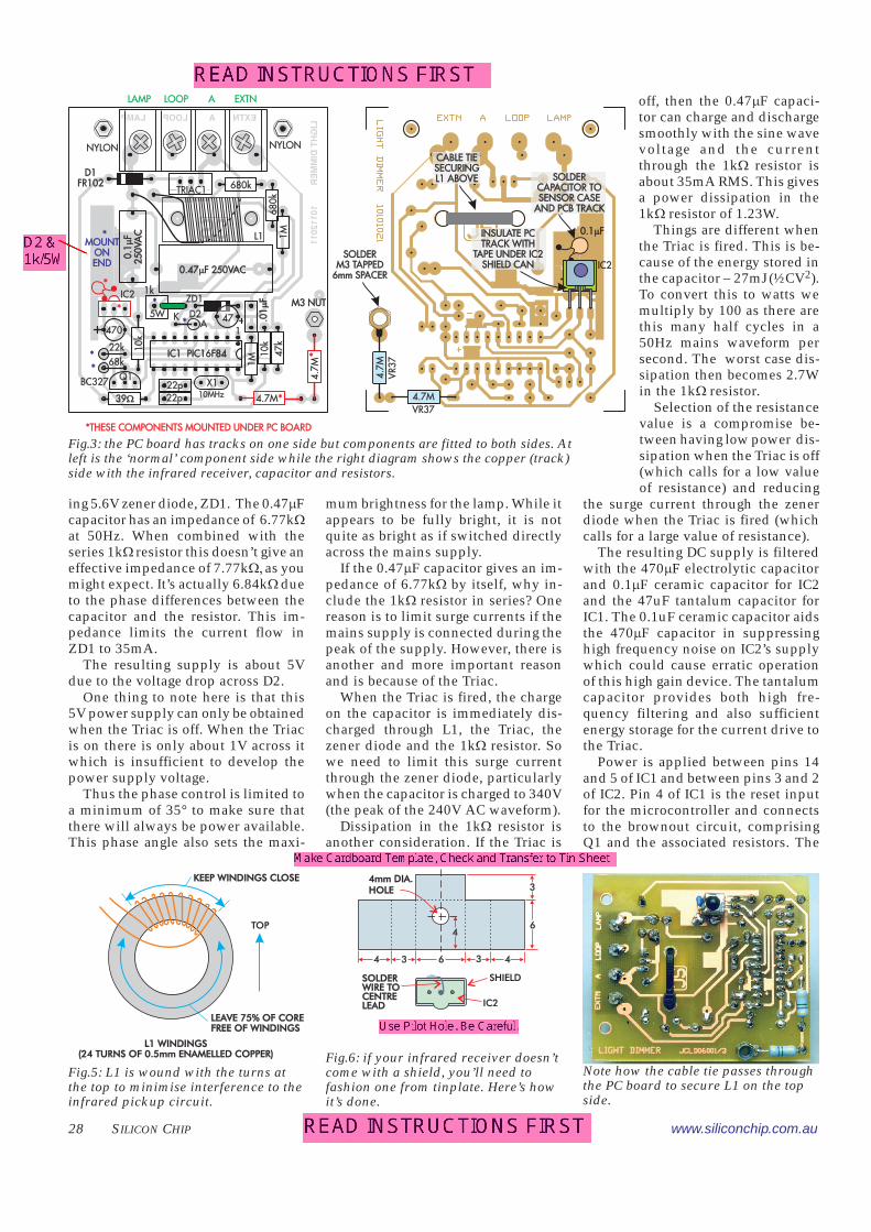
Fig.5: L1 is wound with the turns atthe top to minimise interference to theinfrared pickup circuit.
Fig.6: if your infrared receiver doesn’tcome with a shield, you’ll need tofashion one from tinplate. Here’s howit’s done.
Fig.3: the PC board has tracks on one side but components are fitted to both sides. Atleft is the ‘normal’ component side while the right diagram shows the copper (track)side with the infrared receiver, capacitor and resistors.
Note how the cable tie passes throughthe PC board to secure L1 on the topside.
UNDERSIDEDIMMER BOARD
SOLDERM3 TAPPED
6mm SPACER
SOLDERM3 TAPPED
6mm SPACER
4.7MVR37
4.7
MV
R37
0.1 F�0.1 F�
IC2
SOLDERCAPACITOR TOSENSOR CASE
AND PCB TRACK
SOLDERCAPACITOR TOSENSOR CASE
AND PCB TRACK
INSULATE PCTRACK WITH
TAPE UNDER IC2SHIELD CAN
INSULATE PCTRACK WITH
TAPE UNDER IC2SHIELD CAN
CABLE TIESECURINGL1 ABOVE
CABLE TIESECURINGL1 ABOVE
www.siliconchip.com.au JANUARY 2002 29
circuit is used to bring pin 4 low if thesupply drops below a certain thresh-old.
With a 5V supply, there is sufficientvoltage on the base of Q1 to switch iton, pulling pin 4 to the 5V supply rail.If the supply rail drops, currentthrough the 10k� and 68k� resistorsat Q1s base will also fall. When thesupply voltage reaches 4.68V, the cur-rent through the resistors is 60�A andso the voltage across the 10k� resistoris 0.6V. At this voltage Q1 just beginsto turn off, pulling pin 4 of IC1 low toreset it.
Crystal X1 operates at 10MHz toprovide IC1 with an accurate clocksignal for all the timing signals re-quired in the phase control driver andremote control decoder functions. The22pF capacitors provide the crystalloading to ensure a reliable oscilla-tion when power is applied.
Dimming control inputs are at pin17 for the touch plate and at pin 18 forthe extension. The touch plate is con-nected to pin 17 via two series-con-nected 4.7M� high voltage resistors.It is essential to use the resistors nomi-nated (ie, Philips VR37). As well aslimiting any current flow to a persontouching the touch plate to below26�A, these particular resistors give agood safety margin as they are rated at2.5kV (AC) each. Two resistors in-crease the voltage rating to 5kV givingextra safety.
Normally, the input from the touchplate (pin 17) is held at 5V via the1M� resistor but if the touch plate istouched, the ground capacitance ofthe person will bring the touch plateto ground potential. This effectivelypulls pin 17 down to the same level aspin 5 whenever the active line is aboveground. IC1 can then detect this lowvoltage.
The extension input at pin 18 isnormally held low via the 10k��resis-tor. It is pulled high to the 5V supply,when the extension is activated (inthe same way as the main touch plateabove). The 47k� resistor to pin 18 isused to protect the input from tran-sients or incorrect connections to theextension.
Note that we need to use this exten-sion input for extra touch plates. If wesimply extended the pin 17 input toanother switch plate the extra capaci-tance and pickup from the extra linelength would trigger this high imped-ance input.
IC2 receives and demodulates thecodes from the infrared remote con-trol. It incorporates an amplifier andautomatic gain control plus a 38kHzbandpass filter to accept only remotecontrol signals. It then detects andremoves the 38kHz carrier. The re-sulting signal is applied to the pin 9input of IC1 ready for code detection.The pin 2 and pin 3 inputs provideoptions for one of four remote controlcodes and are set by tying these pinseither high or low with solder linkconnections.
The high gain of IC2 makes thisdevice susceptible to electrical inter-ference from the switching Triac andfrom the suppression components.
The software has been carefully
planned so that the remote controlcoding is only monitored when inter-ference is at a minimum. This inter-ference, however, does cause the gainof the amplifier to be substantiallyreduced due to its internal automaticgain feature which is used to preventoverload in its circuitry. This throt-tling back of gain reduces the range ofthe remote control operation.
To minimise the effect, we haveincluded shielding around the deviceand have wound the suppressioninductor in an unusual manner to sub-stantially reduce any electromagneticradiation.
The zero voltage crossing point forthe mains waveform is detected at pin6 of IC1 via two series connected 680k�
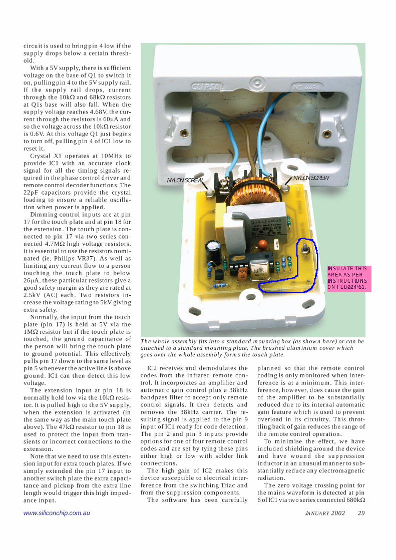
The whole assembly fits into a standard mounting box (as shown here) or can beattached to a standard mounting plate. The brushed aluminium cover whichgoes over the whole assembly forms the touch plate.
NYLON SCREWNYLON SCREW
30 SILICON CHIP www.siliconchip.com.au
Parts List – Touch/RemoteControlled Dimmer
resistors connected to the A2 terminal of the Triac. Detectionof the zero crossing is only made at the negative transition.
If the Triac switches on, the A2 terminal will cause theinput to go high. So zero detection is only available when theA2 terminal goes low, at the end of the positive half cycle ofthe mains waveform. The zero voltage detection signal isalso filtered with a .01�F filter capacitor.
This capacitor causes a substantial shift in the detectedzero crossing point but this is adjusted in software so that the
dimmer operates within the correct phase limits. The filter-ing is necessary to reduce the effects of electricity authoritycontrol tones which may be superimposed on the 50Hzmains. These could otherwise cause rather noticeable flick-ering in the lamp.
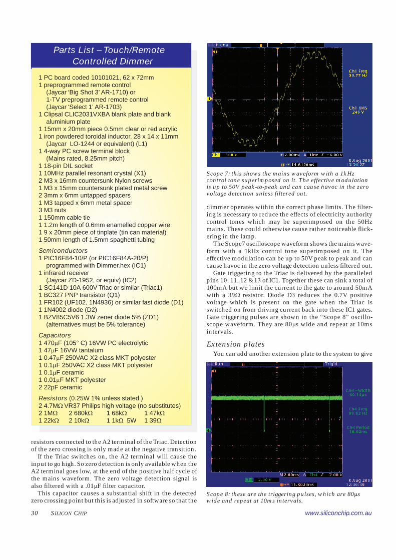
The Scope7 oscilloscope waveform shows the mains wave-form with a 1kHz control tone superimposed on it. Theeffective modulation can be up to 50V peak to peak and cancause havoc in the zero voltage detection unless filtered out.
Gate triggering to the Triac is delivered by the paralleledpins 10, 11, 12 & 13 of IC1. Together these can sink a total of100mA but we limit the current to the gate to around 50mAwith a 39� resistor. Diode D3 reduces the 0.7V positivevoltage which is present on the gate when the Triac isswitched on from driving current back into these IC1 gates.Gate triggering pulses are shown in the “Scope 8” oscillo-scope waveform. They are 80�s wide and repeat at 10msintervals.
Extension platesYou can add another extension plate to the system to give
Scope 8: these are the triggering pulses, which are 80�swide and repeat at 10ms intervals.
Scope 7: this shows the mains waveform with a 1kHzcontrol tone superimposed on it. The effective modulationis up to 50V peak-to-peak and can cause havoc in the zerovoltage detection unless filtered out.
1 PC board coded 10101021, 62 x 72mm1 preprogrammed remote control
(Jaycar ‘Big Shot 3’ AR-1710) or1-TV preprogrammed remote control(Jaycar ‘Select 1’ AR-1703)
1 Clipsal CLIC2031VXBA blank plate and blankaluminium plate
1 15mm x 20mm piece 0.5mm clear or red acrylic1 iron powdered toroidal inductor, 28 x 14 x 11mm
(Jaycar LO-1244 or equivalent) (L1)1 4-way PC screw terminal block
(Mains rated, 8.25mm pitch)1 18-pin DIL socket1 10MHz parallel resonant crystal (X1)2 M3 x 16mm countersunk Nylon screws1 M3 x 15mm countersunk plated metal screw2 3mm x 6mm untapped spacers1 M3 tapped x 6mm metal spacer3 M3 nuts1 150mm cable tie1 1.2m length of 0.6mm enamelled copper wire1 9 x 20mm piece of tinplate (tin can material)1 50mm length of 1.5mm spaghetti tubing
Semiconductors1 PIC16F84-10/P (or PIC16F84A-20/P)
programmed with Dimmer.hex (IC1)1 infrared receiver
(Jaycar ZD-1952, or equiv) (IC2)1 SC141D 10A 600V Triac or similar (Triac1)1 BC327 PNP transistor (Q1)1 FR102 (UF102, 1N4936) or similar fast diode (D1)1 1N4002 diode (D2)1 BZV85C5V6 1.3W zener diode 5% (ZD1)
(alternatives must be 5% tolerance)
Capacitors1 470�F (105° C) 16VW PC electrolytic1 47�F 16VW tantalum1 0.47�F 250VAC X2 class MKT polyester1 0.1�F 250VAC X2 class MKT polyester1 0.1�F ceramic1 0.01�F MKT polyester2 22pF ceramic
Resistors (0.25W 1% unless stated.)2 4.7M� VR37 Philips high voltage (no substitutes)2 1M� 2 680k� 1 68k� 1 47k�1 22k� 2 10k� 1 1k� 5W 1 39�
www.siliconchip.com.au JANUARY 2002 31
both touch and infrared control at asecond, or even third location.
We’ll look at the way this works andhow to put it together next month, whenwe also run through the recommendedtesting procedure. We’ll also look atcoding the remote controls.
ConstructionThe dimmer is constructed on a PC
board coded 10101021 and measuring62 x 72mm. It is mounted on a ClipsalClassic blank plate with a matchingblank aluminium touch plate. The com-pleted dimmer will fit inside a stand-ard metal wall box using a 30mm deepmounting block. Alternatively, it canbe fitted directly inside a Gyprock wallusing standard mounting hardware.
Begin by checking the PC boardagainst the published pattern to ensurethere are no shorts between tracks orany breaks in the copper. Repair theseas necessary.
Now check that the holes are drilledto the correct sizing for the larger com-ponents. The screw terminal mountingholes need to be 1.5mm in diameter,while the PC board mounting holes,the touch plate connection and the ca-ble tie holes to secure L1 should be3mm or 1/8" in diameter.
Install the resistors (except for thetwo 4.7M� values and the 1k� 5Wresistor) first, noting that some aremounted on-end. Use the colour codetable to guide you in selecting eachvalue. You can also check the valueswith a digital multimeter.
Now install the socket for IC1, alongwith the capacitors. The tantalum andelectrolytic types must be oriented withthe correct polarity, as shown on theoverlay. Diodes can be installed nextmaking sure they are also placed withthe correct orientation and that the cor-rect type is placed in each position.The Triac can be placed in position as
well as the screw terminal strip. Tran-sistor Q1 and crystal X1 can now besoldered in place.
The 1k� 5W resistor mounts end-onwith spaghetti sleeving over the wireends. It stands proud of the PC boardby about 5mm to clear diode D2.
Inductor L1 is wound using 24 turnsof 0.5mm enamelled copper wirearound the toroid as shown in Fig.5.
It is not wound in the conventionalmanner with even spacings of the wind-ings around the core; rather the wind-ings are concentrated over about 25%of the circumference.
This unusual winding method is tokeep any stray fields away from theinfrared detector which is susceptibleto picking up interference and produc-ing erratic results. Do not use a com-mercially wound inductor as this willhave even winding spacings around
the core and will prevent the infraredreceiver from operating properly.
When you have finished windingthe core, pot the windings in some 5-minute epoxy. This will reduce theaudible buzz caused by the vibrationof the windings when driving the lampwith phase control.
When the epoxy has set, place theinductor in position on the PC boardwith the windings oriented towardsthe top and secure in place with acable tie wrapped around the circum-ference and through the two holes inthe PC board under the core. The wiresfrom the core are soldered into the PCboard by first cleaning off the insula-tion and tinning the wire ends.
The windings will be in close con-tact with the Triac tab, however, thewindings and tab are at essentially thesame voltage so there is no particularreason to be concerned about insulat-ing the windings from the tab. Youmay, however, wish to place a short
RESISTOR COLOUR CODESNo. Value 4-Band Code (1%) 5-Band Code (1%)
�� 2 4.7M� yellow violet green yellow (NA – must be VR37 type)�� 2 1M� brown black green brown brown black black yellow brown�� 2 680k� blue grey yellow brown blue grey black orange brown�� 1 68k� blue grey orange brown blue grey black red brown�� 1 47k� yellow violet orange brown yellow violet black red brown�� 1 22k� red red orange brown red red black red brown�� 2 10k� brown black orange brown brown black black red brown�� 1 39� orange white black brown orange white black gold brown
CAPACITOR CODES Value IEC Code EIA Code0.47�F 470n 474
0.1�F 100n 1040.01�F 10n 103
.0047�F 4n7 47222pF 22p 22
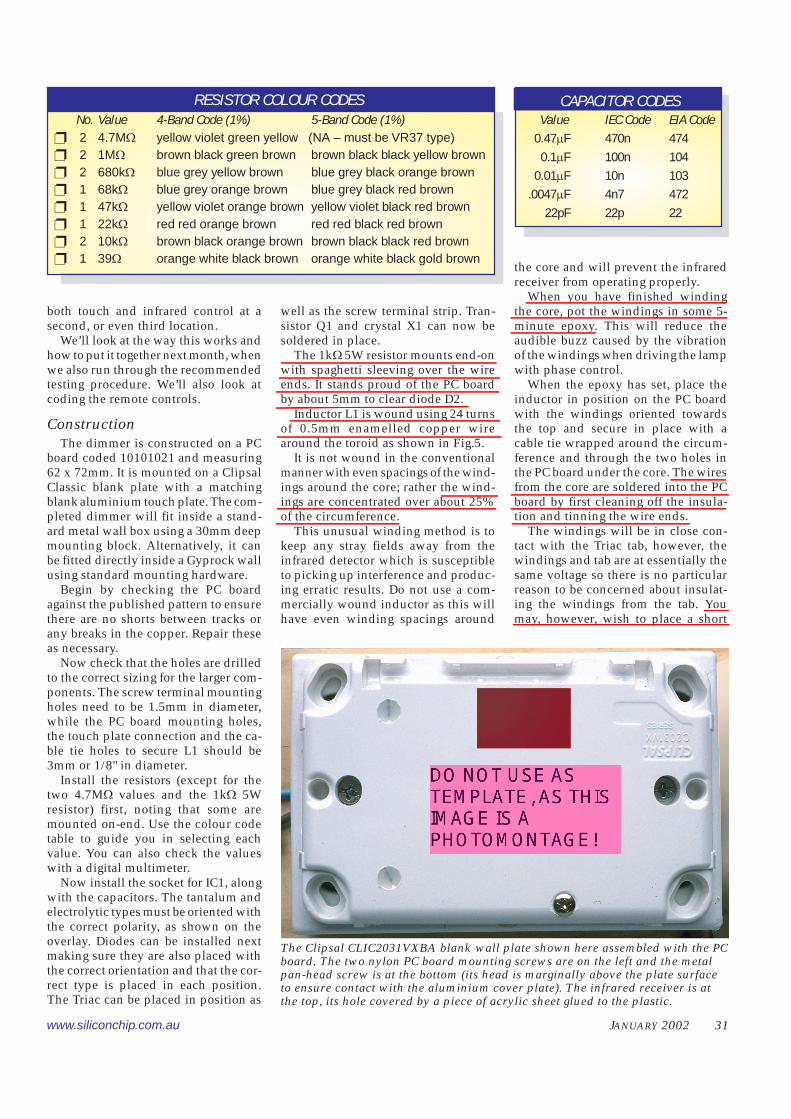
The Clipsal CLIC2031VXBA blank wall plate shown here assembled with the PCboard. The two nylon PC board mounting screws are on the left and the metalpan-head screw is at the bottom (its head is marginally above the plate surfaceto ensure contact with the aluminium cover plate). The infrared receiver is atthe top, its hole covered by a piece of acrylic sheet glued to the plastic.
32 SILICON CHIP www.siliconchip.com.au
SC
length of insulating tape over thewindings in the vicinity of theTriac.
Work can now begin on theunderside of the PC board.
The 4.7M� resistors aremounted first. You must use thespecified Philips VR37 types herebecause they are rated at 2500V.
Use of standard 1W resistorswill jeopardise the electrical safetyof the dimmer. You can recognisethe VR37 types by their light bluebody and yellow tolerance bandrather than a gold one.
Cut the excess lead length offon the top of the PC board. Solderthe 6mm tapped spacer to theboard by first securing it in posi-tion with a screw from the top side ofthe PC board. This will position thespacer correctly before soldering.
If the infrared receiver does not comewith an earthed metal shield, you willneed to make one for it. It can be madeusing some tinplate salvaged from atin can or lid. Cut it out to shape withtin snips and drill out the hole for thereceiver lens. Now fold the shieldaround the body of the receiver. Sol-der a short length of wire between thecentre ground pin to the shield. Theunit is now secured to the undersideof the PC board as shown.
Note that the shield and the copperarea below the sensor are at differentpotentials, so if the shield makes con-tact with the board it will short out the5V supply. Make sure there is no like-lihood of shorting here.
A 0.1�F ceramic capacitor is sol-dered between the shield and PCboard.
Place the PC board onto the Clipsalplastic wall plate with the infraredreceiver to the side which has themounting screws stowed away (un-less, of course, you have already re-moved the screws!). This side hasmouldings which encroach inside ofthe wall plate.
Now mark out the hole positions forthe two mounting holes adjacent the4-way screw terminals and for thetouch contact screw which securesinto the 6mm spacer next to the 4.7M�
resistor. Drill 3mm holes for each. Thetwo mounting holes should be coun-tersunk from the top side so that theNylon mounting screws are flush withthe top face.
The hole for the metal touch con-tact screw is also countersunk a little.
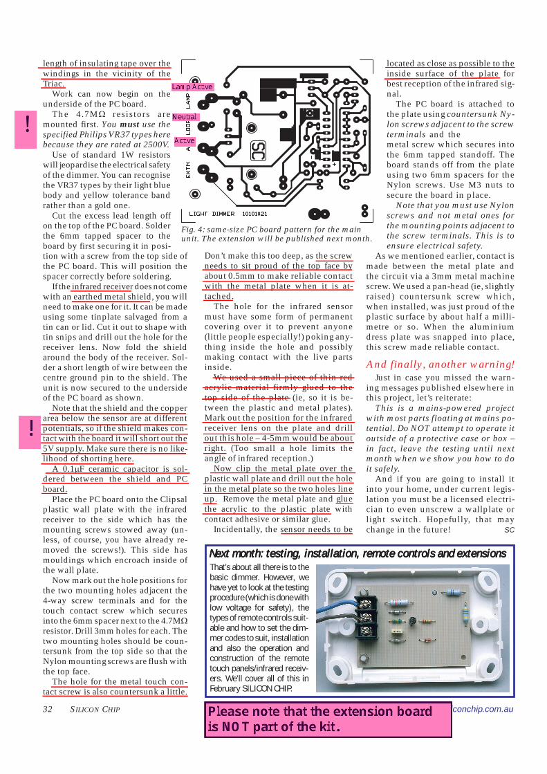
Fig. 4: same-size PC board pattern for the mainunit. The extension will be published next month.
Don’t make this too deep, as the screwneeds to sit proud of the top face byabout 0.5mm to make reliable contactwith the metal plate when it is at-tached.
The hole for the infrared sensormust have some form of permanentcovering over it to prevent anyone(little people especially!) poking any-thing inside the hole and possiblymaking contact with the live partsinside.
We used a small piece of thin redacrylic material firmly glued to thetop side of the plate (ie, so it is be-tween the plastic and metal plates).Mark out the position for the infraredreceiver lens on the plate and drillout this hole – 4-5mm would be aboutright. (Too small a hole limits theangle of infrared reception.)
Now clip the metal plate over theplastic wall plate and drill out the holein the metal plate so the two holes lineup. Remove the metal plate and gluethe acrylic to the plastic plate withcontact adhesive or similar glue.
Incidentally, the sensor needs to be
located as close as possible to theinside surface of the plate forbest reception of the infrared sig-nal.
The PC board is attached tothe plate using countersunk Ny-lon screws adjacent to the screwterminals and the countersunkmetal screw which secures intothe 6mm tapped standoff. Theboard stands off from the plateusing two 6mm spacers for theNylon screws. Use M3 nuts tosecure the board in place.
Note that you must use Nylonscrews and not metal ones forthe mounting points adjacent tothe screw terminals. This is toensure electrical safety.
As we mentioned earlier, contact ismade between the metal plate andthe circuit via a 3mm metal machinescrew. We used a pan-head (ie, slightlyraised) countersunk screw which,when installed, was just proud of theplastic surface by about half a milli-metre or so. When the aluminiumdress plate was snapped into place,this screw made reliable contact.
And finally, another warning!Just in case you missed the warn-
ing messages published elsewhere inthis project, let’s reiterate:
This is a mains-powered projectwith most parts floating at mains po-tential. Do NOT attempt to operate itoutside of a protective case or box –in fact, leave the testing until nextmonth when we show you how to doit safely.
And if you are going to install itinto your home, under current legis-lation you must be a licensed electri-cian to even unscrew a wallplate orlight switch. Hopefully, that maychange in the future!
That’s about all there is to thebasic dimmer. However, wehave yet to look at the testingprocedure (which is done withlow voltage for safety), thetypes of remote controls suit-able and how to set the dim-mer codes to suit, installationand also the operation andconstruction of the remotetouch panels/infrared receiv-ers. We’ll cover all of this inFebruary SILICON CHIP.
Next month: testing, installation, remote controls and extensionsNext month: testing, installation, remote controls and extensionsNext month: testing, installation, remote controls and extensionsNext month: testing, installation, remote controls and extensionsNext month: testing, installation, remote controls and extensions

�� �������������� ������������ www.siliconchip.com.au
���������� ���������� ����������������
���������� ���������� ���������������� ������������� ���������������������������������������������������������������������� ����������� ������ ����������������� ������������������������������������� ���������������� ������
������������ �����
����� ���� ��� �� �������������� ������� ���� ������������ �������� !� ����� ����"
���� ����� �������� ����#� ���� ��� ��$��������������#��������%&%�'�������� ������������ ����������������� ������ ����� ���� �� ������������������������������������ ��������� ��� ������������ �������� ������ ��������� �������� ��������������������� �������������������������� �������� �����������
����� ��������������� ���� �������� ����� ��������������������� ���!��� �������������������� ��!�
'��� ����� ��� ���� (%&)�� ������������*�������*������ ��*���#���� ���� ����*���������������������%�"� ���� � ������� ������� ��������������������� ������� ���������������� ��������� ������������������� �������������������� ��������� ������ �������� ��� ������� �����������������#%
��������������'����+������������*��������������,���
�� ����� -� ���� ���%.%� /�� ���� �� �����
��� ���*�����*������ � ����������$����� ����� �#����� #����� ������� ������,�� ���� ����� ��� ������ #����������%� ��������,��� � ��*� ���� *���������� ��*�������� �+�������� *���#���������*��������(%&)������������������������������#��������� �������%
'�����*���������+������������������� �����#�0� ��� ���� ��*�������� ��� �����*���� �12�������������,�������2)�������������#������������������ �����%
/��������*�������������*���������������,��������,�����*�� �123���������
�*�������#�,���42���������5%5)����$������%� '���� �#������� ��� 12� ���� �����������������������*�������������$��,�%�'����#���������������� ������ $ �������*������������� ���#��%
'���%62������������������������������������,������*������������������� ���,����12%�7�����������742������������������+�����,��,�������������������$�������42%�'����8�������������556������������������������������12����,�������������� ��� ���� ����������� ��� ��� ��������*��������,�����%�/����������� 745�#����������#��������������*�����$��������12" �#����� ����556�� �����������,������*�������� �����%
����������'����+������������*�������*��������
���������������26262655����� ���$*�����95�+�&5 %���#�������� ����� ��� ����� � ��� ��� ���������� ����� �������������:�������#����������:���*$ ���* ���*�������%
������������ ����� ������������ �� ������������ ������������� ������ �������������� ����������������������� ���������������������������������� ��� ���������������������������� ���������������� ��� ������ ���������� ��������� ����������� ����������������������������� �
www.siliconchip.com.au ���� ����� �#
'����� ��������� ���#���� �*������� �����#������+�#��������������������:�#����������� ���� ����������� �� ������$�����������������������������������#������������*��� �� �:�������������� �������+"%�/�������� �*���������������������*���;�����:"#����*����� ��������� �*����������$#���%���������,��� ����������������������������������������*�����$ �*��$������+%
���������� ��������������:������������������������ �����*�����������$�����������*�������������������������$�#��������:�������������:������������$���%�<������������������������%
��#�����:��������������������������������������������8������������������� $�������%�'�������#���� ����� �*��$���� ������ ����� ��� ��� 2%9 � ��� ���$ ���� �#������������������ �*���������������������*���������������������*������! ������� ����%
'������������ �8����������� �������$
�������������������������#����������������������������%�'�����������������#������������������*�������%���������,���*��� �� �������� *��� ����� ��� ���*�������,��*�%%���� �����������&�'%��()$'
�� � �� ��������������������������� ������������*� �� ���� ���� � ��������� ��"� ���������������
����!�����"#�� �����������$ ���� ����� �������������� ���� ����������� �%��&������ ���������"����'()������ �������$����� ��*��������� ����$������ ������ ����������������+����� �������� � ����"#�� ����
����,������������������������������ ��� ������ ���� ��� ����������������� ���� � ��������������������� �������� �������������������� ������$������
���� ��������� ��������������������� ��� ������������#���������������������� ������������� ������������$��� ������ ��� ��������� ���$����-���������.��������� �����/� �0���������� ����� ������ ���������������� ������������� ���������������������������� ������������������������������������������� ���������+��� ���������� ��� � �����
���������
���������
����� ����������������������� �������������� � ����������
���� � � � ������ ������������������������%��&������ � �������� ������������������������� �����������1 �������� ��� ����������������� �������� ����������� �� ���� ������ ��
���� ��������������� � ��
�+ �������������+ ������������ www.siliconchip.com.au
����������������� ������������������������ ��� �
��������������� ��1 Clipsal CLI31WE architrave plate1 Clipsal CLI30MBPRWE ‘Press’ momentary contact switch
��������������� ��1 PC board, code 10101022, 52 x 72mm1 Clipsal CLIC2031VXBA blank aluminium plate and blank plate1 3-way PC screw terminal block (Mains rated, 2.85mm pitch)1 M3 tapped x 6mm metal spacer2 3mm x 6mm untapped spacers2 M3 x 16mm countersunk Nylon screws1 M3 x 15mm countersunk plated metal screw3 M3 nutsNeutral cure silicone sealant
Semiconductors1 BC559 NPN transistor (Q1)2 6.8V 1W 10% zener diodes (ZD1,ZD2)1 1N4148, 1N914 signal diode (D1)
Resistors (5%, 0.25W unless stated)2 4.7M� 1W VR37 Philips high voltage resistors (no substitutes)1 2.2M� 0.25W �������������������������������� �����������1 1M� 1% 0.25W �������� ���������������������� ��� �����������1 220� 1W ������������������������������� ��� ������
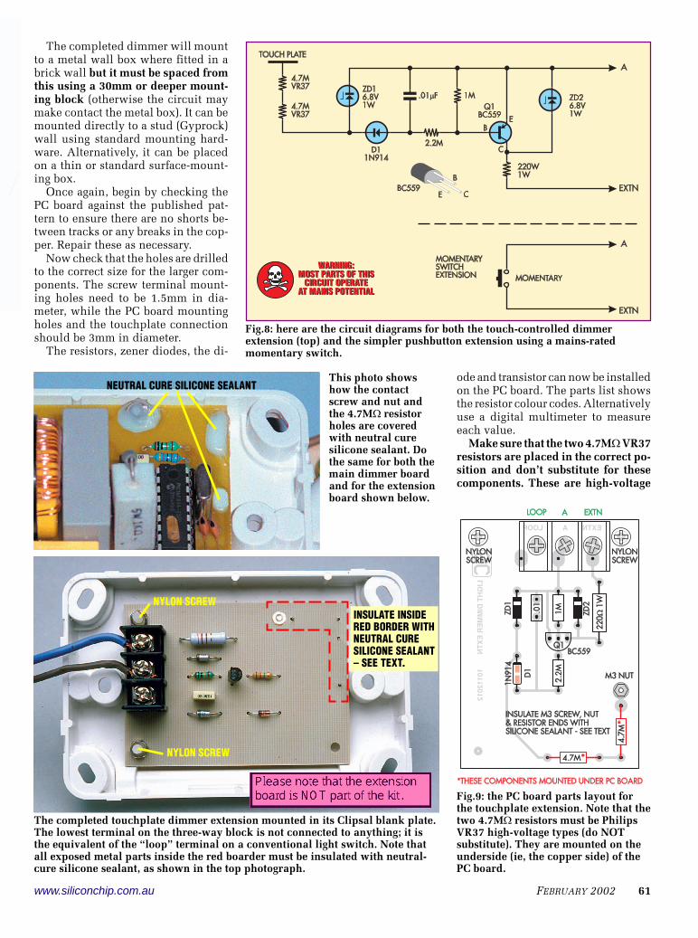
�� � �� ��������������+�,�(�)%��������� ������������� ���!���� �� �"�!������������������������������������������������ ������������������ "���� ���� � ���� ��� ��� ������ ��������� �������
'��������������������������������# ���#���� ��� ����!$#��� ��� �����%�'�� �*����������#���������� ��������$���������#�������������������+����������� �� ����������������� ������ ��*���%� ���������� �������������� ��������� ����������������������������������� ������� ������������ ������&�'%���� � �� �
���������*����+��������������������#����$
������� ��*� ���� ��� ��*�� ������*�����%��*���*����������������� ���������#���� �����*����� �*��� ��������������������*���,��3�� �������� ����:���*������������������*�� ���� ������ ���3���������� #������ ��� ����:� ���� �����$�����������*���������#$,��������������$��� ���������25��������*��%�'������$=*�������������� *�:�������*���*������������������������%-��� �� ��� !������*� ��� �� ���
����������������������� ���������������� ������������������ ���� ����������� ���� ������!�������������������������������� ����������.!� ����� !��� �� � ���� �� ����� ��
����������� ��� � � ���� !��� ���� ������ ������������� ���� ��������������� ��������� ����������.������ �� ������� �� ���� ����
����!���������������� ���!�����������!���������������� ���� ������������� �������� � ������������� �� ����� �������� ���� ��������������� ������"���� � ������ ����������� ����#�%��������������*��� ��� ����������� �������� ������$����������*���,������������ *��� ����%/��� ���������������������
���� ���� ��!� �������� ���� ��� �'��������#�������*�������� �������������*������ ���� ��*�������%� /�� ��������*�������� ����� ���� � ����:� ����� �����������,��*��������������,�������*���%
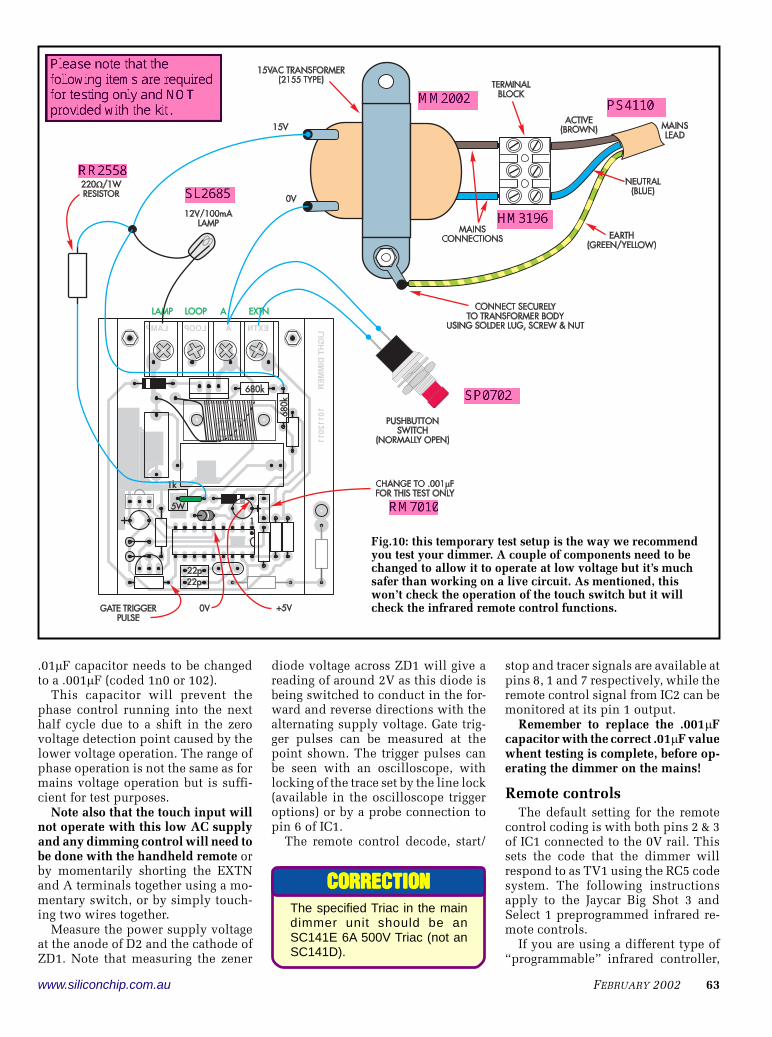
'��� ��������� �����������*�� �������*���*����������������� ���������#�������%26%���*�#�����������25�2%5>�*����������������� ���#���������,$�������*��29����566 ���� ���%�>�*������5299������������#����������� ���� �����,����� �������� ���������:������#�������%�'���������#�������$��������������������� �������%
�������������������#����*��������8����,�����������������������,�����,��������������� ����������������� ��� ���2:�������������������?.6:�������������������,���%� ��*� #���� ����� �� 556�2>�������������������*�������������$���������������2:��9>�����������������
www.siliconchip.com.au ���� ����� �$
����23��������� ���$�����������������$������� �����$ ������$ �����������4�� ����� ��� �� ����������� ����������� ���� ������ � ����������� ��� ������������5�������������� ������ ������������������4������ ���+���� �5���������� ������ �� ������ ��������������������������������������� ���� ��� �������� ��
%62�������������������������������������%662����������2�6����265"%
'���� ���������� #���� ���,���� ��������� �������� �*������ ����� ���� ��+������ �������*�� ��� �� ������ ��� ���� 8���,�������������������������*������������#���,����������������%�'���������������������������������������� �������� �����,������������������*������*���$����������������*������%-����� �������������������
�������������� ����� �� ����!������!���������������������������������������������������������� � ��������� ��������� ���� �@'��������� ���������������*������� �$ ��������#���� ��������� ������*��$�����#��#�������������%
)���*���������#����*�����,����������������������45�������������������742%� ����� ����� ���*����� ���� 8����
������,��������������742�#������,�����������������*���5������������������������#��������������*�������������$#����������,����������������#��������������������*�����,������%�;��������$���� �*����� ���� ��� ���*���� ��� ������������#�%�'������������*����������� ����� #���� ��� ������������ � #������:������������������������������������:��,�������� ��� �������������������������������"��������������������������������?����/�2%
'��� �� ���� �������� ������ � �����A
�����������������������������,���������������. �2�����&���������,��� �#���������� ���������������������� �/�5������� ��������������������2��*��*�%)�������� �� �������� �� ���#�0
�����������������������#�0����������� ����� ��������������������������������������������� 1
�������������'�������*��� �������� ���� ���� �� ���
������������������#��������������5�B�!���/�2������������������6�����%�'�������� ���� ����� ����� ���� �� ��� #�����������������'2�*���������<�9���������� %� '��� �����#���� �����*������������ ��� ���� C������ D��� E���� !� ���E������2���������� ��������������$ ������������%
/����*�����*������������������������F������ ����G� ��������� ����������
The specified Triac in the maindimmer unit should be anSC141E 6A 500V Triac (not anSC141D).
��������������������������������������������������
�& �������������& ������������ www.siliconchip.com.au
�����������/6������20������ ����/7���6 ��)0���� ���� ��� ���� �8�$����9����� �����
��*���������������������������������$��������������������������*���������������������������������������=*�� ���%��*����*����������� ��� ��������� ����#������������������ ��%
/����*�����*���������D���E����!���$ ��������������*�����������������������2H2%�'����������������������������E�'����'��*��������������������������$�������� ������ �*�����%� '��� ����� ��I�4�#���������%���#������������* ���2H2�*����������* �����*�������������� �����������%
'���E������2��� ������������ *�����������������22(2(%������������������4�����������������"��*�����������#�����$������������������������� %�����������* �����22(2(�*����� �����* ������*�����%�'���E������2��� �����������#����������������������� ���#���������������������'2�����%
'����� ��������������������*���������5�B�!����/�2���������*���#�������D���E����!������ ������� �����������%��*��������������*����������������������'2����������� ����������������$��������������� �������������������� �����*����*��%
��������,��� ������*���,�� �������������� ����������,������� ���*����*��� �� ���������� ����� ���� ����%� '��F������������G����������#����������������������������������%������������������ ���������� �������������:���������������5�B�!��������6������ ���������� ��� ���:��� #���� �� :����� ���� ��$
����������������J9�����%�����+� ��� �����E'2�����������
��������!���������������������:����������������������J9�����%�'���D���E���!� ����� ������ #���� ����� ����� ��� �������������������#�����%�����E'2 ������E�'�����E'�����������������������������(5(%�������������*������������ ��� ������ � ���� ,��*�� ����� ���E'��*��������������%�/����*��������$������*����������<����'��*�������$���������������%�'���������������� ����� �� ���*���������������������*�����' ��<����E'"���������������#��������������%
/����*�������������<5�������������D���E����! �����������,���������������������� ���������������)�'���*������%>���������������������*������� ����������������,���� �������� �*���������������� ���������������������������$��������������%
��#�,�� � ���� �<5� ������� #������������ ���� �������� ��� )*��� ���� ����������� ������ ��� ��������� ������� �����%�E�� ��� ������������#���� ��
������������ ��������������� ���� �������������������������� ������������������������������������������������ ����!������ ����������������������������������� "�#$���� ���������#$��%#�$��� �� �� &&������������������������������������������������������������� '�#�$���(������)������������� �&������������ ��������������� ����!����������� ��������������������������������������� ���&� ����������� �&�� ��&��� �������������������!���������� � ������������������������������������ �$��&� ����������� �&������������* &������� ���������������������������������������������� ��$���&� �� &&�� �&������������+�� ���� ��� ������������������������������������ , (�� �� �����+,��� (���-�.�-,+�.�*/�����(�*/���0����� �(�������,1�2� ����������������������� ���&� ����������� �&������������0����( 3��(�������,1�%� ������������������� ���&� ����������� �������������������* 3�� �(�������-4)�2� �������������������� ���#���� �(��&� ����������� �&������������* 3�� �(�������-4)�%� �������������������� ���#���� �(��&� ��&�������������� ��������5������� && �������������������������������������������� ����!���������� � ������������������������������������ �$�������&��6������ �7������ ����������������� ���� ���18������&��6������& ����� ��� ��� �� � ����� �������������������������������� �9��18�� �����18�����������(��:� ������������������������������������ ;$�������$�/<� 3�� ���������: �����& ��5,� ����������� ��#;-�=��$-/,��������� ���� �������������� �3������ ����������������������� ��$>
www.siliconchip.com.au ���� ����� �,
����2;����������������=��"#�� �������� ���� ����������������� �����������"#�� ��������������������������� ���
����� ������������ ���� �������������������� ��� ��� ���*����� ��� ����$�� ����������� ��������� ��� ����$���������������> ������������� �������� ����� ������$�
����22������ ���������� ���$������;���$�� ���������������������+������� �� ����� �������������������<���������;���$�������� ������� ��������������������� �������+����������������������� ������$�� ��������������������������������� �� ����� ������� ��
���������������������������������������������������� �� ��� ���������������������� ������� �� ��� ���������������������� ������� �� ��� ���������������������� ������� �� ��� ���������������������� ������� �� ��� ���������������������� �������������������� ��� �������� �������� ����������������� ��� �������� �������� ����������������� ��� �������� �������� ����������������� ��� �������� �������� ����������������� ��� �������� �������� ��
���������������� !"#$%����������&���������������� !"#$%����������&���������������� !"#$%����������&���������������� !"#$%����������&���������������� !"#$%����������& �������� �� ���� ���' � �(������)�� �������� �� ���� ���' � �(������)�� �������� �� ���� ���' � �(������)�� �������� �� ���� ���' � �(������)�� �������� �� ���� ���' � �(������)���������*���)� ������������ � ���������������*���)� ������������ � ���������������*���)� ������������ � ���������������*���)� ������������ � ���������������*���)� ������������ � ��������
���������( ���� �� �����������$���������( ���� �� �����������$���������( ���� �� �����������$���������( ���� �� �����������$���������( ���� �� �����������$
��������#������#?<#;3)2'@74���������������� �� ������������ ���������������������� ����������
�,����*�������������������������*�������������������������$������#������������ ����������������=*�� ���%
>�� ���� ���� *��� ���� �<2� ������� �������� �#����� ���������������� ����������������������)*��"�����*�������)*���������������� ���������)*����������������'2��������%�'����������������*���$����*��������#���������#�� *���������������,��������*���#�������������������������������<%
������������������������ ���,����*��� � ���������������������%662��
�������������:����6%62��K�4�������#������*���,��3�L'����� �������*��������������������������������+������
�� �������#���������*�������*�������#��������������� �*������������,������#��������"������� �$,��$��*��������*��������:"�#����%�'����+��������#��������=*�����������,���������������������+��������*������������+��������#���#����������������������@'�����*����������� ��%�/������������������������+�������5$#����#�����#�����������*������,�����������������������������#�����������������������������������%
'��� ����� ��� ��������� ������ ��������+���������������� ��� ��� ������ ���� #����� ����� ��=*���� ����������� ��$��������*������������������ ���� �������#�������%�'���� ��� ���*�������� ���� ����� ��� ����� ���,����� ��� ��������� �����
�#������%�>�����#�����#�������������5$#����#�����#�����������#����#����*�������+����������������� ��%���*����*������������ � ����������������#�������� �����+���������*�������� �� ��� ��� ���,���� �� ���� ��� � �� �� �����������%�'��� � ��������#������������*���������������$���,�� �#����� �*���*�� � �:���� ��� ������� ���� ������������#���������������� ������*�����������������*���*��%
���������������� ������������ ������*���M*���#�� ������� ��*�� � �*�� ��� ���� ������������ #������ ���� '����� ������*�����#�������������,���������� � �����2:��9>��������� ����8���������������������������������6%2�������6%(&�� ���������������%
'����� ������������ *�����������������#�������������,��������� ������ �������������������������������������%�>���������������������& ��������������������*�����������% SC
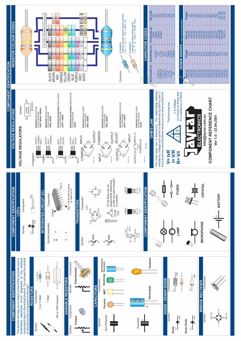
VO
LTA
GE
RE
GU
LA
TO
RSCO
MP
ON
EN
TID
EN
TIF
ICA
TIO
N
PO
SIT
IVE
78X
X,L
M340,L
M2940
RE
GU
LA
TO
RT
O-2
20
PA
CK
AG
E
NE
GA
TIV
E
79X
X,L
M320RE
GU
LA
TO
RT
O-2
20
PA
CK
AG
E
PO
SIT
IVE
AD
JU
STA
BL
E
LM
317,L
M350
RE
GU
LA
TO
RT
O-2
20
PA
CK
AG
E
NE
GA
TIV
EA
DJU
STA
BL
E
LM
337
RE
GU
LA
TO
RT
O-2
20
PA
CK
AG
E
PO
SIT
IVE
78L
XX
RE
GU
LA
TO
RT
O-9
2P
AC
KA
GE
AD
JU
STA
BL
E
LM
317,L
M350
RE
GU
LA
TO
RT
O-3
PA
CK
AG
E
NE
GA
TIV
E
79X
X,L
M320RE
GU
LA
TO
RT
O-3
PA
CK
AG
E
Bottom
vie
wO
UT
PU
T
INP
UT
CO
MM
ON
PO
SIT
IVE
78X
X,L
M340
RE
GU
LA
TO
RT
O-3
PA
CK
AG
E
OU
TP
UT
CO
MM
ON
INP
UT
CO
MM
ON
Top
vie
w
OU
TP
UT
INP
UT
CO
MM
ON
INP
UT
Top
vie
w
INP
UT
OU
TP
UT
AD
JU
ST
OU
TP
UT
Top
vie
w
OU
TP
UT
INP
UT
AD
JU
ST
INP
UTTop
vie
w
Sym
bo
l
Co
mp
on
en
t
VO
LTA
GE
RE
GU
LA
TO
RS
Vo
lta
ge
Re
gu
lato
rIN
OU
T
CO
MM
ON
OU
TP
UT
CO
MM
ON
INP
UT
Bottom
vie
w
INP
UT
AD
JU
ST
OU
TP
UT
Bottom
vie
w
SO
T-3
0
OU
TP
UT
(2)
CO
MM
ON
(3)
INP
UT
(1)
Bottom
vie
w
Sym
bo
lC
om
po
ne
nt
NP
NB
C CE E
BP
NP
TO
-5
E
B
C
TO
-3E
(D)
B(G
)C
(S)
(FE
T)
TO
-92
(72)
TO
-22
0
BE
C
C
TO
-22
0(A
)
BE
E
C
CE
BT
O-9
2B
od
yh
as
pin
assig
nm
en
tsd
ep
en
din
go
nth
esu
bty
pe
ind
ica
ted
inb
racke
ts.
E(K
) TO
-12
6C(A
)
B(G
)C
(A)
(FE
T)
Pla
stic
are
a(f
ront)
Meta
lare
abehin
d
CO
MP
ON
EN
TID
EN
TIF
ICA
TIO
N
A+
K-
A+
Sym
bo
lC
om
po
ne
nt
Sym
bo
l(e
xa
mp
le)
Co
mp
on
en
t
Pin
1
Cu
tou
t
Pin
7
(to
the
left
of
cu
tou
to
rm
ark
on
IC)
MIC
RO
PH
ON
E
FU
SE
S
CR
YS
TA
L
BA
TT
ER
Y+
-
LA
MP
4.00MHz
'AA'C
OM
PO
NE
NT
IDE
NT
IFIC
AT
ION
LE
D's
TR
AN
SIS
TO
RS
INT
EG
RA
TE
DC
IRC
UIT
(IC
)
V IR
OH
M’S
LA
W
V=
IxR
I=V
/RR
=V
/I
Th
em
ost
ba
sic
law
ine
lectr
on
ics.
Th
ere
latio
nsh
ipb
etw
ee
nre
sis
tan
ce
,vo
lta
ge
an
dcu
rre
ntis
de
term
ine
dby
Ohm
’sLaw
(*).
Ifyo
ukn
ow
two
ou
toft
he
thre
eva
lue
syo
uca
nw
ork
ou
tth
eth
ird
.
Th
efo
rmu
las
are
:
Vis
Vo
lta
ge
Iis
Cu
rre
nt
inA
mps
an
dR
isre
sis
tan
ce
inO
hm
s
CO
MP
ON
EN
TR
EF
ER
EN
CE
CH
AR
T
Ve
r1
.0-
23
.04
.20
01
kit
s@
jay
ca
r.c
om
.au
CA
PA
CIT
OR
CO
DE
S
Na
no
fara
ds
(n)
-0
.22
nF
1n
F4
.7n
F1
0n
F4
7n
F1
00
nF
47
0n
F1
00
0n
F
ZE
NE
RD
IOD
ES
(1W
AT
TU
NL
ES
SS
PE
CIF
IED
)
Pa
rtn
o.
1N
47
28
1N
47
29
1N
47
30
1N
47
31
1N
47
32
1N
47
33
1N
47
34
1N
47
35
1N
47
36
1N
47
37
1N
47
38
1N
47
39
1N
47
40
1N
47
41
1N
47
42
1N
47
43
Vo
lta
ge
3V
33
V6
3V
94
V3
4V
75
V1
5V
66
V2
6V
87
V5
8V
29
V1
10
V11
V1
2V
13
V
Mic
rofa
rad
s(u
)- -
0.0
01
uF
0.0
04
7u
F0
.01
uF
0.0
47
uF
0.1
uF
0.4
7u
F1
uF
This
section
will
help
you
tom
atc
hsom
eof t
he
sym
bols
used
inschem
atics
(ele
ctr
onic
circuit
dia
gra
ms)
toth
ephysic
al
com
ponentused
inth
eactu
al p
roduct.
You
will
see
the
sym
bol
on
the
left
and
the
com
ponento
nth
eright.
Co
mp
on
en
t
4or
5B
and
1W
att
5W
or
10W
Cera
mic
¼or
½W
att
Co
mp
on
en
t
Po
ten
tio
mete
r
CO
MP
ON
EN
TID
EN
TIF
ICA
TIO
N
Cera
mic
MK
TG
reen
cap
Tan
talu
mE
lectr
oly
tic
No
n-P
ola
ris
ed
Ele
ctr
oly
tic
Co
mp
on
en
t
A+
K-
Co
mp
on
en
t A+
K-
RE
SIS
TO
RS
VA
RIA
BL
ER
ES
IST
OR
SS
ym
bo
lC
om
po
ne
nt
CA
PA
CIT
OR
S
BR
IDG
ER
EC
TIF
IER
DIO
DE
/Z
EN
ER
DIO
DE
+
RE
SIS
TO
RC
OL
OU
RC
OD
ES To
lera
nc
eM
ulti
plie
r3
rdD
igit
GO
LD
SILV
ER
1000
000
1000
00
1000
0
1000
100
101
10%
5%
9876543210
9876543210
9876543210
2%1%
BLA
CK
BR
OW
NR
ED
OR
AN
GE
YE
LLO
WG
RE
EN
BLU
EP
UR
PLE
GR
EY
WH
ITE
(5B
AN
D)
ye
llo
w-p
urp
le-b
lack-b
row
n-b
row
n=
4-
7-
0-
1-
1%
=4
K7
1%
(4B
AN
D)
ora
ng
e-p
urp
le-y
ello
w-g
old
=3
-7
-4
-1
0%
=3
70
K1
0%
Exa
mp
les:
Pic
ofa
rad
s(p
)1
00
pF
22
0p
F1
00
0p
F4
70
0p
F- - - - -
EIA
co
de
10
12
21
10
24
72
10
34
73
10
44
74
10
5
Pa
rtn
o.
1N
47
44
1N
47
45
1N
47
46
1N
47
47
1N
47
48
1N
47
49
1N
47
50
1N
47
51
1N
47
52
1N
47
53
1N
47
54
1N
47
61
1N
53
49
B1
N5
35
2N
1N
53
74
Vo
lta
ge
15
V1
6V
18
V2
0V
22
V2
4V
27
V3
0V
33
V3
6V
39
V7
5V
12
V5
W1
5V
5W
75
V5
W
Sym
bo
l
AC
AC
+-
Sym
bo
l
Tri
mp
ot
Sym
bo
lC
om
po
ne
nt
Non-P
ola
rised
Pola
rised
Sym
bo
l A+
K-
Dio
de
Zen
er
Dio
de
Sym
bo
l
A+
K-
+
+