Embed Size (px)
Citation preview

www.eae.com.tr
Cakmakli Mahallesi, 2. Cadde,119. Sokak, No:12 34522Kirac-Hadimkoy-Istanbul-TURKEYTel: +90 (212) 886 23 90Fax: +90 (212) 886 24 20
T E
ME 04
IEC 60439-2 s
Busbar Systems
100-160-225 A
ISO 900114001
NTAL E MM AN NO AR GI EV MNE E ND TN SA YY STI TL EA M
U SQ
EA
E h
as
full
rig
ht
to m
ake
an
y re
visi
on
s o
r ch
an
ces
on
th
is c
ata
log
ue w
itho
ut
an
y p
rio
r n
otic
e.
23
/03
/20
07
2
.00
0 A
U
LA
Ş T
AN
ITIM
/ S
.A./
61
2 4
0 6
6

w w w . e a e . c o m . t r
CONTENTS
2-3
4
5
6
7
8
9
10-12
13-17
18
19
20-21
22
23
24
Introduction
Order Code System
Technical Characteristics
Standard Components
Special Straight Length
Flexible Elbow
Expansion Module
Feeder Boxes
Tap-Off Boxes
Fixing Elements
MK Joint Installation
MK Tap-Off Box Installation
EC Certificate of Conformity
Product Overview
Project Design Form

A 16 5 7 -
IP 55 5
MK
4
5
7
T DSS
10
16
10
16
22
100
160
100
160
225
4
E L E K T R İ K
E MKLINEOrder Code System
Aluminium ACopper C
Busbar Type
Conductor Type
CodeNumber of
Conductors
Protection Degree
BUSBAR TYPE
CONDUCTOR TYPE
PROTECTION DEGREE
COMPONENT
BUSBAR CURRENT
CONDUCTOR CONFIGURATION
Conductor Configuration
Configuration
L1,L2,L3,N,PE(Housing)
L1,L2,L3,N,PE+Housing
L1,L2,L3,N,CPE,PE(Housing)
4 wire
5 wire
5 wire (Clean Earth)
Busbar Current
Components
BusbarRated Current
Aluminium
Copper
Code
Standard Length
Special Length
Flexible Elbow
Expansion Unit
Feeder Box 1
Feeder Box 2
Central Feeder Box
STD
X
FD
DT
B1
B2
BO
22
72,15
72,15
4,5
5,2
2,48
198
4,5x17
0,294
0,193
0,352
14,88
25
15
15
225
12,5
7,5
7,5
0,249
0,257
0,362
L
L1
L1
L1
L1
L2
L2
L2
L3
L3
L3
L2
L4
L4
L4
F
F
F
F
FF
L
1.00
0.50
0.125
0.25
0.25
DV=aÖ3.L.I.(R.Cosj+X .Sinj) 10L
-3
a
Volt
10 16
IEC 60439-2: 2000
42,9
42,9
mm² 72,15
72,15
22,65
22,65 mm²
2,35 kg/m 2,7 2,75
2,5
2,48
kg/m
kW/m
2,9
2,48
3,0
2,48
mm²
mmxmm
198 198 198
V
V
Ue
Ui
1000
4,5x10,5 4,5x17 4,5x6
0,850 0,496 0,955 mW/m
0,216 0,160 0,257 mW/m
0,877 0,521 0,989 mW/m
kAIcw
kAIcw
kAIp
kAIp
W/m 8,507 12,69 9,5551
²I R
5,25
3,15
3,15
kA 10,2
6,12
6,12
5,25
3,15
3,15
Ip
100A 160 100In
3,5
2,1
2,1
kA 6
3,6
3,6
3,5
2,1
2,1
rmsIcw
0,675 0,401 0,79420
1
1
1
mW/mR
R
X
Z
0,825 0,437 0,838 mW/mR
0,868 0,469 0,888 mW/mZ
1000
f Hz
IP
50 / 60
55
10
42,9
42,9
3,3
3,7
2,48
198
4,5x10,5
0,414
0,198
0,459
10,60
10,2
6,12
6,12
160
6
3,6
3,6
0,419
0,363
0,415
16
5
E L E K T R İ K
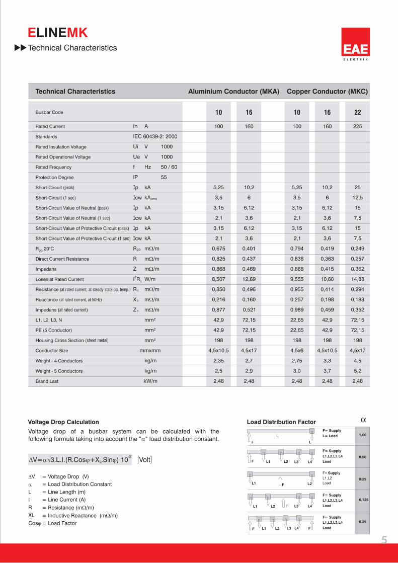
E MKLINETechnical Characteristics
Voltage Drop Calculation
Voltage drop of a busbar system can be calculated with thefollowing formula taking into account the “a“ load distribution constant.
= Voltage Drop (V)
= Load Distribution Constant
= Line Length (m)
= Line Current (A)
= Resistance (mW/m)
= Inductive Reactance (mW/m)
= Load Factor
DV
a
L
I
R
XL
Cosj
Standards
Busbar Code
Rated Current
Aluminium Conductor (MKA)Technical Characteristics Copper Conductor (MKC)
L1, L2, L3, N
PE (5 Conductor)
Weight - 4 Conductors
Weight - 5 Conductors
Brand Last
Housing Cross Section (sheet metal)
Rated Operational Voltage
Conductor Size
Resistance (at rated current, at steady state op. temp.)
Reactance (at rated current, at 50Hz)
Impedans (at rated current)
Short-Circuit Value of Neutral (1 sec)
Short-Circuit Value of Protective Circuit (1 sec)
Short-Circuit Value of Neutral (peak)
Short-Circuit Value of Protective Circuit (peak)
Loses at Rated Current
Short-Circuit (peak)
Short-Circuit (1 sec)
20R 20°C
Direct Current Resistance
Impedans
Rated Insulation Voltage
Rated Frequency
Protection Degree
Load Distribution Factor
F= Supply
L= Load
F=
L1,L2,L3,L4
Load
Supply
F=
L1,L2,L3,L4
Load
Supply
F=
L1,L2,L3,L4
Load
Supply
F=
L1,L2
Load
Supply

MK S T D
3000385 500 500 500 500 615
385500500500500615
50
115
NL1L2L3PE
6
E L E K T R İ K
E MKLINEStandard Straight Length Dimensions
Sample Order:160A, Aluminium, IP55, 4 conductors
MKA 1654-STD
Standard Straight Length
BUSBAR TYPE
CONDUCTOR TYPE
PROTECTION DEGREE
COMPONENT
BUSBAR CURRENT
CONDUCTOR CONFIGURATION
Standard length of busbar is 300cm.
Provision of a total of 10 plug-in points onboth sides of the busbar are providedas a standard feature.
Code
Code
35899
35898
35897
71581
70769
71597
71571
70761
71593
160
100
160
225
100
Current (A)
Current (A)
4
5
5
4
5
5
4
5
5
4
5
5
4
5
5
Conductors
Conductors
MKC 1054-STD Busbar
MKC 1055-STD Busbar
MKC 1057-STD Busbar
MKC 2254-STD Busbar
MKC 2255-STD Busbar
MKC 2257-STD Busbar
Aluminium (Al)
Copper (Cu)
STD-Standard Length Busbar / Codes
Configuration
Configuration
L1, L2, L3, N, PE(Housing)
L1, L2, L3, N, PE+Housing
L1, L2, L3, N, CPE, PE(Housing)
L1, L2, L3, N, PE(Housing)
L1, L2, L3, N, PE+Housing
L1, L2, L3, N, CPE, PE(Housing)
L1, L2, L3, N, PE(Housing)
L1, L2, L3, N, PE+Housing
L1, L2, L3, N, CPE, PE(Housing)
L1, L2, L3, N, PE(Housing)
L1, L2, L3, N, PE+Housing
L1, L2, L3, N, CPE, PE(Housing)
L1, L2, L3, N, PE(Housing)
L1, L2, L3, N, PE+Housing
L1, L2, L3, N, CPE, PE(Housing)
71583
71561
70753
MKC 1654-STD Busbar
MKC 1655-STD Busbar
MKC 1657-STD Busbar
71595
71573
70768
MKA 1054-STD Busbar
MKA 1055-STD Busbar
MKA 1057-STD Busbar
MKA 1654-STD Busbar
MKA 1655-STD Busbar
MKA 1657-STD Busbar

(A) (A)mm
(A)mm
100
160
225
10,5
17
-
6
10,5
17
MK
X
50
115
A
NL1L2L3PE
50
115
NL1L2L3PE
7
E L E K T R İ K
E MKLINE
Current Aluminium Copper
Special Straight LengthDimensions
Sample Order:225A, Copper, IP55, 5 conductors, 100cm.
Special straight length busbars aremanufactured as standard at 1m, 1,5m and 2m.
MKC 2255-100
Special StraightLength
X SpecialStraight Length
(cm)
X- L / CodesSpecial Straight ength Busbar
Code
Code
160
100
160
225
100
Current (A)
Current (A)
4
5
5
4
5
5
4
5
5
4
5
5
4
5
5
Conductors
Conductors
Aluminium (Al)
Copper (Cu)
Configuration
Configuration
MKA 1654-X Special straight length
MKA 1655-X Special straight length
MKA 1657-X Special straight length
-X Special straight length
MKA 1055-X Special straight length
MKA 1057-X Special straight length
MKA 1054
MKC 1054-X Special straight length
MKC 1055-X Special straight length
MKC 1057-X Special straight length
MKC 1654-X Special straight length
MKC 1655-X Special straight length
MKC 1657-X Special straight length
MKC 2254-X Special straight length
MKC 2255-X Special straight length
MKC 2257-X Special straight length
71247
71229
70707
35822
35834
35809
71245
70731
71265
71239
70729
71259
71257
71237
70721
L1, L2, L3, N, PE(Housing)
L1, L2, L3, N, PE+Housing
L1, L2, L3, N, CPE, PE(Housing)
L1, L2, L3, N, PE(Housing)
L1, L2, L3, N, PE+Housing
L1, L2, L3, N, CPE, PE(Housing)
L1, L2, L3, N, PE(Housing)
L1, L2, L3, N, PE+Housing
L1, L2, L3, N, CPE, PE(Housing)
L1, L2, L3, N, PE(Housing)
L1, L2, L3, N, PE+Housing
L1, L2, L3, N, CPE, PE(Housing)
L1, L2, L3, N, PE(Housing)
L1, L2, L3, N, PE+Housing
L1, L2, L3, N, CPE, PE(Housing)
BUSBAR TYPECONDUCTOR TYPE
PROTECTION DEGREE
COMPONENT
BUSBAR CURRENT
CONDUCTOR CONFIGURATION
Conductor Cross SectionsFor non-standard modules, please contact our company.

MK
290
320
290
320
50
115
NL1L2L3PE
50
115
NL1L2L3PE
8
E L E K T R İ K
4
5
5
4
5
5
71403
70889
71425
71413
70897
71429
100 Al100 Cu
160 Al160 Cu225 Cu
E MKLINEFlexible ElbowsCodes
FD Flexible Elbow (Al/Cu)
CodeCurrent(A) Conductors Copper (Cu)
MKC 1055-FD Flexible Elbow
MKC 1057-FD Flexible Elbow
MKC 1054-FD Flexible Elbow
MKC 2254-FD Flexible Elbow
MKC 2255-FD Flexible Elbow
MKC 2257-FD Flexible Elbow
Flexible Elbow(Vertical)
Flexible Elbow(Horizontal)
Sample Order:225A, Copper IP55, 4 conductors
MKC 2254 - FD
BUSBAR TYPE
CONDUCTOR TYPE
PROTECTION DEGREE
COMPONENT
BUSBAR CURRENT
CONDUCTOR CONFIGURATION
MK
650 mm
50
115
NL1L2L3PE
4
5
5
4
5
5
100 Al100 Cu
160 Al160 Cu225 Cu
9
E L E K T R İ K
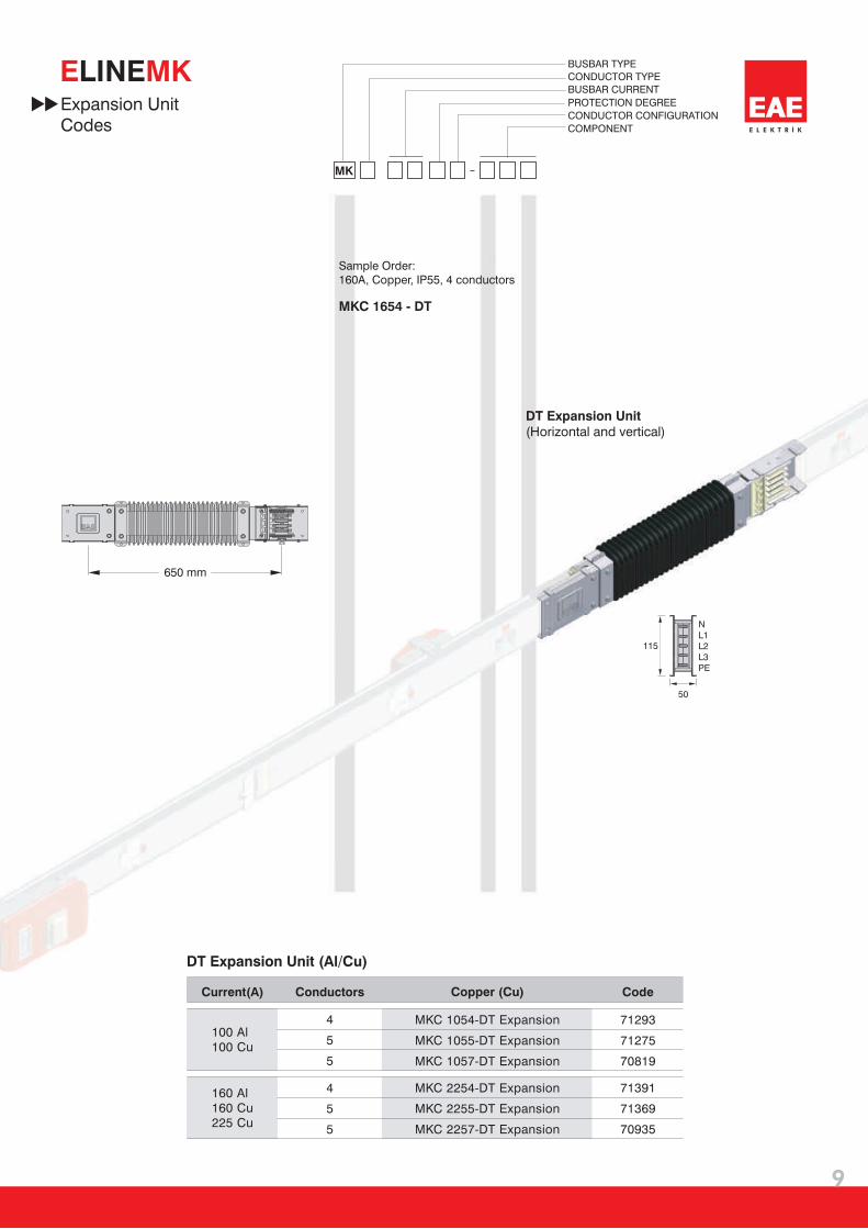
71275
70819
71293
71369
70935
71391
E MKLINEExpansion UnitCodes
Sample Order:160A, Copper, IP55, 4 conductors
MKC 1654 - DT
DT Expansion Unit(Horizontal and vertical)
DT Expansion Unit (Al/Cu)
CodeCurrent(A) Conductors Copper (Cu)
DT Expansion
MKC 1055-DT Expansion
MKC 1057-DT Expansion
MKC 1054-
MKC 2254-DT Expansion
MKC 2255-DT Expansion
MKC 2257-DT Expansion
BUSBAR TYPECONDUCTOR TYPE
PROTECTION DEGREE
COMPONENT
BUSBAR CURRENT
CONDUCTOR CONFIGURATION

MK
50
115
NL1L2L3PE
max 120°
100 Al160 Al
4
5
5
4
5
5
71485
71127
71545
71489
71137
71549100 Cu160 Cu225 Cu
10
E L E K T R İ K
E MKLINEFeeder BoxesCodes
Sample Order:160A, Copper IP55, 5 conductors
MKC 1655 - B1
B1 Feeder Box 1
B1 Feeder Box 1 (Al) B1 Feeder Box 1 (Cu)
CodeCurrent(A) Conductors Copper (Cu)CodeCurrent(A) Conductors Aluminium (Al)
MKA 1654-B1 Feeder Box 1
MKA 1655-B1 Feeder Box 1
MKA 1657-B1 Feeder Box 1
MKC 2254-B1 Feeder Box 1
MKC 2255-B1 Feeder Box 1
MKC 2257-B1 Feeder Box 1
BUSBAR TYPE
CONDUCTOR TYPE
PROTECTION DEGREE
COMPONENT
BUSBAR CURRENT
CONDUCTOR CONFIGURATION
100 25M32
M40*160 32
225
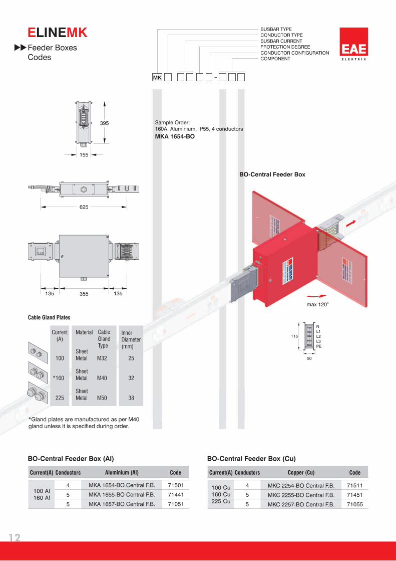
*Gland plates are manufactured as per M40gland unless it is specified during order.
38M50
Cable Gland Plates
MaterialCurrent(A)
CableGlandType
InnerDiameter(mm)
SheetMetal
SheetMetal
SheetMetal
103
179
133
283

MK
50
115
NL1L2L3PE
max 120°
4
5
5
71463
71111
71523 4
5
5
71473
71115
71533100 Al160 Al
100 Cu160 Cu225 Cu
11
E L E K T R İ K
E MKLINE
Sample Order:160A, Aluminium IP55, 4 conductor
MKA 1654 - B2
B2 Feeder Box 2
B2 Feeder Box 2 (Al)
MKA 1654-B2 Feeder Box 2
MKA 1655-B2 Feeder Box 2
MKA 1657-B2 Feeder Box 2
B2 Feeder Box 2 (Cu)
MKC 2254-B2 Feeder Box 2
MKC 2255-B2 Feeder Box 2
MKC 2257-B2 Feeder Box 2
Feeder BoxesCodes
BUSBAR TYPE
CONDUCTOR TYPE
PROTECTION DEGREE
COMPONENT
BUSBAR CURRENT
CONDUCTOR CONFIGURATION
CodeCurrent(A) Conductors Copper (Cu)CodeCurrent(A) Conductors Aluminium (Al)
100 25M32
M40*160 32
225 38M50
Cable Gland Plates
MaterialCurrent(A)
CableGlandType
InnerDiameter(mm)
SheetMetal
SheetMetal
SheetMetal
103
133
283
179
*Gland plates are manufactured as per M40gland unless it is specified during order.
MK
50
115
NL1L2L3PE
71501
71441
71051
4
5
5
4
5
5
71511
71451
71055
100 Al160 Al
100 Cu160 Cu225 Cu
max 120°
12
E L E K T R İ K
E MKLINE
BO-Central Feeder Box
BO- (Cu)Central Feeder BoxBO- (Al)Central Feeder Box
MKA 1654-BO Central F.B.
MKA 1655-BO Central F.B.
MKA 1657-BO Central F.B.
MKC 2254-BO Central F.B.
MKC 2255-BO Central F.B.
MKC 2257-BO Central F.B.
Sample Order:160A, Aluminium, IP55, 4 conductors
MKA 1654-BO
Feeder BoxesCodes
BUSBAR TYPE
CONDUCTOR TYPE
PROTECTION DEGREE
COMPONENT
BUSBAR CURRENT
CONDUCTOR CONFIGURATION
CodeCurrent(A) Conductors Copper (Cu)CodeCurrent(A) Conductors Aluminium (Al)
100 25M32
M40*160 32
225 38M50
Cable Gland Plates
MaterialCurrent(A)
CableGlandType
InnerDiameter(mm)
SheetMetal
SheetMetal
SheetMetal
135 135
395
155
625
355
*Gland plates are manufactured as per M40gland unless it is specified during order.
16 A
13
0
210
98
13
E L E K T R İ K
E MKLINE
BUSBAR TYPE
BOX TYPE
PROTECTIONDEGREECONDUCTORS
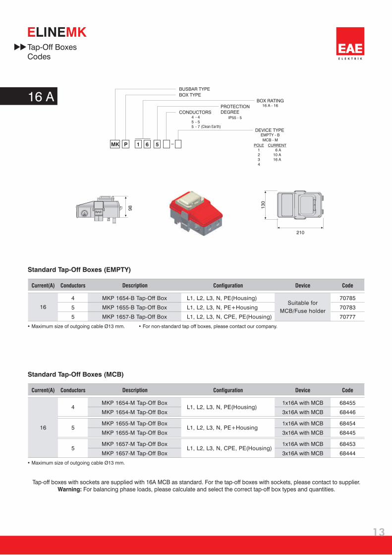
MK P 1 6 5
BOX RATING16 A - 16
IP55 - 5455
- 4- 5- 7 (Clean Earth)
DEVICE TYPEEMPTY - B
MCB - M
POLE1234
CURRENT6 A
10 A16 A
Tap-Off BoxesCodes
Code
Code
68455
68446
68454
68445
68453
68444
70785
70783
70777
16
16
Current(A)
Current(A)
4
5
5
4
5
5
Conductors
Conductors
1x16A MCB
3x16A with MCB
with
1x16
3x16A with MCB
A with MCB
1x16
3x16A with MCB
A with MCB
Configuration
Configuration
Device
Device
MKP 1654-M Tap-Off Box
MKP 1654-M Tap-Off Box
MKP 1655-M Tap-Off Box
MKP 1655-M Tap-Off Box
MKP 1657-M Tap-Off Box
MKP 1657-M Tap-Off Box
MKP 1654-B Tap-Off Box
MKP 1655-B Tap-Off Box
MKP 1657-B Tap-Off Box
Description
Description
• Maximum size of outgoing cable Ø13 mm. For non-standard tap off boxes, please contact our company. •
• Maximum size of outgoing cable Ø13 mm.
L1, L2, L3, N, PE(Housing)
L1, L2, L3, N, PE+Housing
L1, L2, L3, N, CPE, PE(Housing)
L1, L2, L3, N, PE(Housing)
L1, L2, L3, N, PE+Housing
L1, L2, L3, N, CPE, PE(Housing)
Standard Tap-Off Boxes (MCB)
Standard Tap-Off Boxes (EMPTY)
Tap-off boxes with sockets are supplied with 16A MCB as standard. For the tap-off boxes with sockets, please contact to supplier.Warning: For balancing phase loads, please calculate and select the correct tap-off box types and quantities.
Suitable for
MCB/Fuse holder

16
5
335
97
,5
12
0
90
40 A
14
E L E K T R İ K
E MKLINE
MK P 4 0 5
BUSBAR TYPE
BOX TYPE
PROTECTIONDEGREECONDUCTORS
BOX RATING40 A - 40
IP55 - 5455
- 4- 5- 7 (Clean Earth)
EMPTY - B
MCB - M
POLE1234
CURRENT32 A40 A
Tap-Off BoxesCodes
68443
68442
68441
68431
68430
68429
40
40
4
5
5
4
5
5
MKP 4054-M Tap-Off Box
MKP 4055-M Tap-Off Box
MKP 4057-M Tap-Off Box
• • Maximum size of outgoing cable Ø22 mm.As standard with 3x40A automatic fuse is used in boxes.
L1, L2, L3, N, PE(Housing)
L1, L2, L3, N, PE+Housing
L1, L2, L3, N, CPE, PE(Housing)
3 x 40A
with MCB
MKP 4054-B Tap-Off Box
MKP 4055-B Tap-Off Box
MKP 4057-B Tap-Off Box
Standard Tap-Off Boxes (MCB)
Standard Tap-Off Boxes (EMPTY)
CodeCurrent(A) Conductors Configuration DeviceDescription
CodeCurrent(A) Conductors Configuration DeviceDescription
• Maximum size of outgoing cable Ø22 mm. For non-standard output boxes, please contact our company. •
L1, L2, L3, N, PE(Housing)
L1, L2, L3, N, PE+Housing
L1, L2, L3, N, CPE, PE(Housing)
Suitable for
MCB/Fuse holder
Tap-off boxes with sockets are supplied with 40A MCB as standard. For the tap-off boxes with sockets, please contact to supplier.Warning: For balancing phase loads, please calculate and select the correct tap-off box types and quantities.
DEVICE TYPE
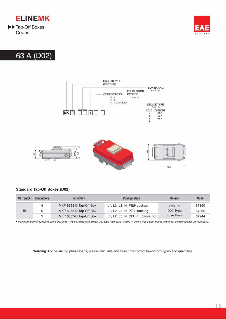
63 A (D02)
16
5
335
97
,5
12
0
90
15
E L E K T R İ K
E MKLINE
MK P 5
BUSBAR TYPE
BOX TYPE
PROTECTIONDEGREECONDUCTORS
BOX RATING63 A - 63
IP55 - 5455
- 4- 5- 7 (Clean Earth)
DEVICE TYPED02 - D
POLE1234
CURRENT40 A50 A63 A
Tap-Off BoxesCodes
Standard Tap-Off Boxes (D02)
• Maximum size of outgoing cable Ø22 mm. • As standard with 3x63A D02 type fuse base is used in boxes. For output boxes with plug, please contact our company.
67890
67962
67944
63
4
5
5
MKP 6354-D Tap-Off Box
MKP 6355-D Tap-Off Box
MKP 6357-D Tap-Off Box
L1, L2, L3, N, PE(Housing)
L1, L2, L3, N, PE+Housing
L1, L2, L3, N, CPE, PE(Housing)
CodeCurrent(A) Conductors Configuration DeviceDescription
3x63 A
D02 Type
Fuse Base
Warning: For balancing phase loads, please calculate and select the correct tap-off box types and quantities.

16
5
335
97
,5
12
0
90
80 A
E L E K T R İ K
16
E MKLINE
MK P 5
BUSBAR TYPE
BOX TYPE
PROTECTIONDEGREECONDUCTORS
BOX RATING80 A - 80
IP55 - 5455
- 4- 5- 7 (Clean Earth)
DEVICE TYPEEMPTY - BMCB - M
POLE1234
CURRENT40 A50 A63 A80 A
Tap-Off BoxesCodes
Standard Tap-Off Boxes (EMPTY)
Standard Tap-Off Boxes (MCB)
• • Maximum size of outgoing cable Ø22 mm.As standard with 3x80A MCB.
68422
68421
68420
80
4
5
5
3 x 80A
with MCB
MKP 8054-M Tap-Off Box
MKP 8055-M Tap-Off Box
MKP 8057-M Tap-Off Box
L1, L2, L3, N, PE(Housing)
L1, L2, L3, N, PE+Housing
L1, L2, L3, N, CPE, PE(Housing)
CodeCurrent(A) Conductors Configuration DeviceDescription
• Maximum size of outgoing cable Ø22 mm. • For non-standard output boxes, please contact our company.
71357
71355
71353
80
4
5
5
MKP 8054-B Tap-Off Box
MKP 8055-B Tap-Off Box
MKP 8057-B Tap-Off Box
L1, L2, L3, N, PE(Housing)
L1, L2, L3, N, PE+Housing
L1, L2, L3, N, CPE, PE(Housing)
CodeCurrent(A) Conductors Configuration DeviceDescription
Suitable for
MCB/Fuse holder
Tap-off boxes with sockets are supplied with 80A MCB as standard. For the tap-off boxes with sockets, please contact to supplier.Warning: For balancing phase loads, please calculate and select the correct tap-off box types and quantities.

BRA9-2
BRA10
BRA11-05
BRA11-10
BRA11-15
BRA11-20
98878
98877
99974
99973
99354
99355
71343
17
E L E K T R İ K
E MKLINEFixing Elements
Fixing Elements
MK-UT Universal Fixing Element
CodeDescription
CodeDescription
Wall Installation
Floor Installation
Steel Dowel (M8)
Extension Unit (M8)
Threaded Rod (M8x500)
Threaded Rod (M8x1000)
Threaded Rod (M8x1500)
Threaded Rod (M8x2000)
Roof Installation
Steel
Dowel (M8)
Extension Unit
Threaded Rod
Steel
Dowel (M8)
Extension Unit
Threaded Rod
MK-UT
Universal
Fixing
Element

Fixing Elements
35842
18
E L E K T R İ K
E MKLINE
71557
Steel
Dowel (M8)
Extension Unit
Threaded Rod
MK "C" Type Universal Fixing Element
MK Vertical Fixing Element
CodeDescription
CodeDescription
Wall Installation
Floor Installation
Vertical Shaft Installation
Roof Installation
MK
"C" Type
Universal
Fixing
Element
3a 4a
2a
2b
1
3
5.1
2
4
5.2
E L E K T R İ K
19
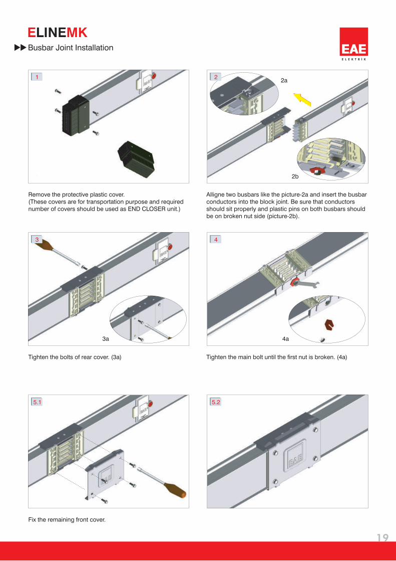
E MKLINEBusbar Joint Installation
Tighten the bolts of rear cover. (3a) Tighten the main bolt until the first nut is broken. (4a)
Fix the remaining front cover.
Remove the protective plastic cover.(These covers are for transportation purpose and requirednumber of covers should be used as END CLOSER unit.)
Alligne two busbars like the picture-2a and insert the busbarconductors into the block joint. Be sure that conductorsshould sit properly and plastic pins on both busbars shouldbe on broken nut side (picture-2b).

CLICK
CLICK
2.3
3.1 3.2
1
2.2
2.1
4.1 4.2
19
20
E L E K T R İ K
E MKLINETap-Off Box Installation Instructions (40-63-80A)
Attach the cable, which has a cross section suitable to theswitch current, before you install the box to the busbar.
When closing the cover of the box; insert thesafety-tongue into the seat by finger touch.
When the tap-off box cover is at open position; locate thebox contacts to the busbar plug area by aligning them.
Lock the cover lock by pressing it towards the arrow direction.
Be sure that the retaining springs are attached to the busbar.
Empty tap-off boxes are produced with MCB connection cables.When the tap-off boxes are used as monophase, the switch will be connected to one of the phase cables.Remaining phase cables should be insulated by using cable terminals for your safety.In order to balance phases of busbar, connected loads to the tap off boxes should be calculated carefully.

E MKLINE
CLICK
1 2
3 4
5.1 5.2
5.3
E L E K T R İ K
21
Remove the cover screws. Open the cover.
Connect a cable, which has suitable cross section,to the switch, before you install the box to the busbar.
Tighten the removed cover screws.
Be sure that, the box is fixed to the busbar properly.
Fix the box contacts to the busbar plugarea by aligning them.
Tap-Off Box Installation Instructions (16A)
Empty tap-off boxes are produced with MCB connection cables.When the tap-off boxes are used as monophase, the switch will be connected to one of the phase cables.Remaining phase cables should be insulated by using cable terminals for your safety. In order to balance phases of busbar, connected loads to the tap off boxes should be calculated carefully.
E L E K T R İ K
Certificate
EAE Elektrik A.Ş.
22
E L E K T R İ K
E MKLINE
EC CONFORMITY CERTIFICATE
Product Group
Standard
Type Tests
1- Temperature Rise
2- Dielectric Characteristics
3- Short Circuit Resistance
4- Continuity of the Protective Circuit
5- Creepage Distances
6- Mechanical Operation
7- Protection Class
8- Electrical Characteristics
9- Structural Strength
10-Crush Strength
11-Insulation Material Thermal Strength
Manufacturer
E-Line MK Busbar Energy Distribution System
IEC 60439-2
EAE Elektrik A.Ş.
Cakmakli Mahallesi, 2. Cadde, 119. Sokak, No:12 34522 Kirac-Hadimkoy-IstanbulTel: +90 (212) 886 23 90 Fax: +90 (212) 886 24 20 http://www.eae.com.tr
EAE Elektrik A.Ş.
Cakmakli Mahallesi, 2. Cadde, 119. Sokak,No:12 34522 Kirac-Hadimkoy-Istanbul
This certificate of conformity is prepared on performing the type tests specified and
obtaining its reports at independent laboratories according to the standard.

E L E K T R İ K
(100...225A MK)
PRODUCT OVERVIEW
Product Overview
E L E K T R İ K
23
E MKLINE
The busbar system shall have Al conductors for 100A and 160A or
Cu conductors for 100A, 160A and 225A.
The busbar system shall conform to the following phase configuration.
a- 4 conductors
b- 5 conductors
c- 5 conductors (with clean earth)
The insulation voltage of the busbar shall be 1000V.
The busbar housing shall be of 0,60mm thick epoxy painted galvanized sheet metal. (RAL 7038)
The Al conductors shall be plated with nickel and then with tin, the Cu conductors
shall be plated only with tin. The plating shall be continuous along the conductor.
The busbar joint shall have a single bolt construction and
the nut of main joint bolt shall be a double headed nut, tightened at 20Nm.
The busbar housing shall be continuously clamped together by roll forming method.
10 plug-in windows shall be located on a standard 3m length.
Busbar and tap off boxes shall be IP55 protection class under normal operation conditions.
IP protection covers of plug-in points shall be hinged and lockable from single point.
Tap off boxes up to 16A shall be removed from the busbar before opening their lids.
The tap off boxes above 16A, shall have the following mechanical and electrical safety features.
a- The box shall only be plugged in and removed from the busbar at “OFF” position.
b- The energy on the connected load shall be automatically cut, when the box lid is open.
c- The tap off box shall comply IP2X requirements, while it is plugged into the busbar and the lid is open.
All tap off box contacts shall be silver plated.
Jawed tap off box contacts shall be reinforced by steel springs.
Busbar systems shall be tested and certified according to IEC 60439-2 by international laboratories.
Busbar system shall have flexible elbows and expansion units.
Manufacturing facility of busbar systems shall have ISO 9001 and ISO 14001 certification.
1-
2-
3-
4-
5-
6-
7-
8-
9-
10-
11-
12-
13-
14-
15-
16-
17-
L1 / L2 / L3 / N / PE(Housing)
L1 / L2 / L3 / N / PE+Housing
L1 / L2 / L3 / N / CPE / PE(Housing)
24
E L E K T R İ K
E MKLINEProject Design Form
Ple
ase
du
blic
ate
th
is p
ag
e fo
r yo
ur
ow
n u
se.
Quantit
yC
om
po
nen
t
Co
mp
on
en
t Lis
t
Item
Nam
e :
Date
:
Sig
natu
re :
Prepared by
Co
mp
an
y
:
Pro
ject
:
Pro
ject
No
:

Compact Busbar Distribution System800...6300A
Plug-in Busbar Distribution System160...800A
Small Power Plug-in Busbar Distribution System100-160-225A
Plug-in Busbar Distribution System40-63A
Multi-Conductor Lighting Busbar System25-32-40A
Lighting Busbar System25-32-40A
Multi Conductor Trolley Busbar System35...250A
Underfloor Ducting Systems
Raised Floor Energy Distribution Systems25...63A
CableTray Systems
E-LINE KB
E-LINE KO
E-LINE MK
E-LINE KAP
E-LINE DL
E-LINE KAM
E-LINE TB
E-LINE DK
E-LINE DKY
E-LINE UK