Embed Size (px)
Citation preview
Volume 1 • Issue 4 • 1000102
Open AccessResearch Article
Kamada et al., Adv Robot Autom 2013, 2:1 DOI: 10.4172/2168-9695.1000102
Keywords: Underactuated mechanism; Task-based design; Principalcomponent analysis; Elastic elements
1. IntroductionIt is often suggested that hand prostheses and robot grippers must
possess a kinematic structure that is similar to those of the natural human hand [1-4]. Such structure allows better adaptation of the gripper to the size and the shape of the grasped object and better cosmetic effect. Anthropomorphic hands with a large number of joints are highly dexterous, but their independent joint control requires a large number of actuators. While human muscles can generate very high energy per unit weight, the electrical motors used in the artificial hand design do not have high power-to-weight ratio. Therefore, the mimicking of the natural hand structure with presently available technology often leads to serious design difficulties and the designed mechanisms become large, heavy and less powerful. As a solution to the problem, many design concepts of robotic hands with fewer actuators than degree-of-freedom (DoF) have been introduced [5-12]. In such concepts, one actuator is connected with several joints and operates them simultaneously. In this research field such mechanisms are often called “underactuated” mechanisms. The idea of the underactuated gripper mechanisms is suggested by various studies of human hand motions which showed that specific human movement tasks can be performed by a small number of variables [13]. The underactuated grippers do not have the grasping dexterity of the human hand but they can replicate natural movements on a satisfactory way for a significant set of human movement tasks. Although the accuracy of the synthesized underactuated mechanisms is lower than the accuracy of the mechanisms with the same kinematic structure and independently controlled joints, the approach allows the synthesis of hands with simple structures that possess high functionality and precise motions for the named set of tasks. The underactuated gripper mechanisms were further improved by adding elastic elements or self-adaptive transmission between the output of each actuator and the corresponding robot hand joint [5-12]. Such a solution increases gripper adaptability and allows successful handling of objects with bigger variations in shape and size. Improvement of the functionalities of the underactuated robot hands have been widely studied [14-16]. Ciocarlie et al. [14], introduced a quasistatic analytical tool for underactuated hands performing grasping tasks. Balasubramania et al. [15], studied the motion and force capabilities of a variety underactuated mechanisms. Prattichizzo et al. [16], explored gripper manipulability by
introducing manipulability ellipsoids of underactuated hands.
However, developers of underactuated robotic hands usually follow their own specific approaches for simplification of the natural hand structure that are applicable only to the particular kinematic concept. In our previous research, we developed a systematic design method for simplification and synthesis of underactuated mechanisms without elastic components [17]. In this approach, the drive mechanism of the hand is presented as a composition of specific structures called linear dependent drives (LDD) with parameters that are calculated and optimized for the predefined set of movement tasks by using special criteria.
In the present paper we propose a systematic approach for design of underactuated robot hands with several elastic elements based on further development and adaptation of the task-based design method [17]. We introduce a criterion for analyzing the level of participation of each joint for the given tasks set and the result is used further for selection of the kinematic parameters and elasticity coefficients of the designed underactuated mechanism by minimizing the same criterion. We have verified the proposed method with a few numerical design examples and here we provide some of the key results that demonstrate its effectiveness.
2. Linear Dependent Drive and Underactuated MechanismIn this study, we concentrate on mechanisms in which the number
of actuators r is smaller than the number of the joints n (n>r). The relationship between the angular positions of the gripper joints and the displacements of the actuators is described as follows:
*Corresponding author: Shoichiro Kamada Graduate School of Engineering, Nagoya University Furo-cho, Chikusa-ku, Nagoya, 464-8603, Japan, Tel: +81-52-789-5583, Fax: +81-52-789-5589, E-mail: [email protected]
Received December 21, 2012; Accepted January 28, 2013; Published February 06, 2013
Citation: Kamada S, Obinata G, Stefanov D (2013) A Study of the Underactuated Mechanisms with Compliance. Adv Robot Autom 2: 102. doi:10.4172/2168-9695.1000102
Copyright: © 2012 Kamada S, et al. This is an open-access article distributed under the terms of the Creative Commons Attribution License, which permits unrestricted use, distribution, and reproduction in any medium, provided the original author and source are credited.
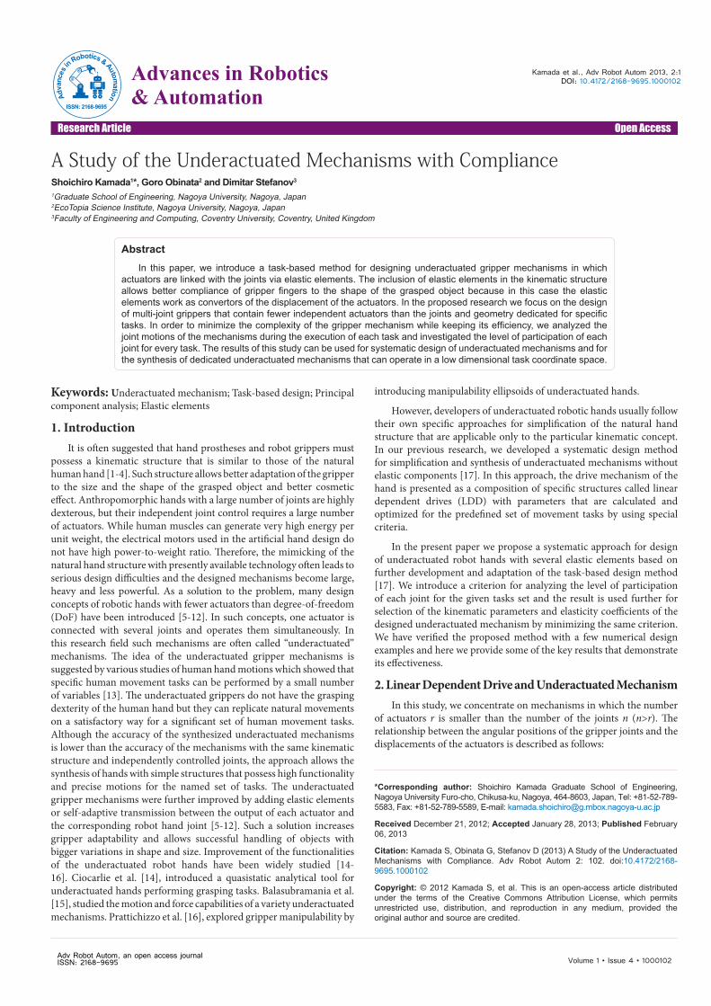
AbstractIn this paper, we introduce a task-based method for designing underactuated gripper mechanisms in which
actuators are linked with the joints via elastic elements. The inclusion of elastic elements in the kinematic structure allows better compliance of gripper fingers to the shape of the grasped object because in this case the elastic elements work as convertors of the displacement of the actuators. In the proposed research we focus on the design of multi-joint grippers that contain fewer independent actuators than the joints and geometry dedicated for specific tasks. In order to minimize the complexity of the gripper mechanism while keeping its efficiency, we analyzed the joint motions of the mechanisms during the execution of each task and investigated the level of participation of each joint for every task. The results of this study can be used for systematic design of underactuated mechanisms and for the synthesis of dedicated underactuated mechanisms that can operate in a low dimensional task coordinate space.
A Study of the Underactuated Mechanisms with ComplianceShoichiro Kamada1*, Goro Obinata2 and Dimitar Stefanov3
1Graduate School of Engineering, Nagoya University, Nagoya, Japan2EcoTopia Science Institute, Nagoya University, Nagoya, Japan3Faculty of Engineering and Computing, Coventry University, Coventry, United Kingdom
Adv Robot Autom, an open access journalISSN: 2168-9695
Advances in Robotics & AutomationAd
vanc
es in
Robotics& Automation
ISSN: 2168-9695
Citation: Kamada S, Obinata G, Stefanov D (2013) A Study of the Underactuated Mechanisms with Compliance. Adv Robot Autom 2: 102. doi:10.4172/2168-9695.1000102
Page 2 of 7
Volume 1 • Issue 4 • 1000102
θ(t)=Zq(t)+c(t) (1).
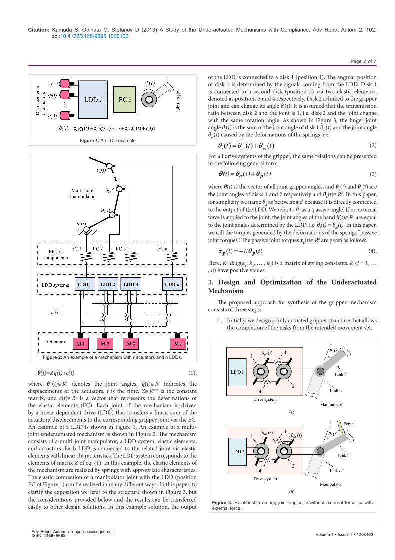
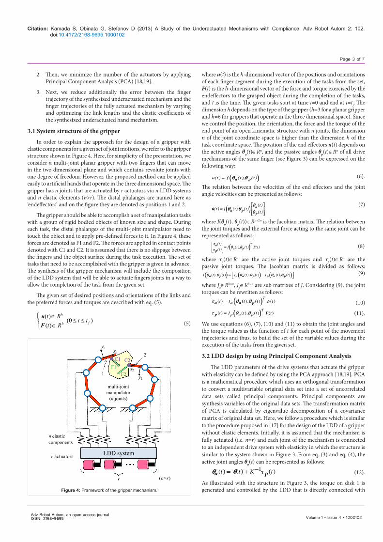
where θ (t)∈Rn denotes the joint angles, q(t)∈Rr indicates the displacements of the actuators, t is the time, Z∈Rn×r is the constant matrix, and c(t)∈Rn is a vector that represents the deformations of the elastic elements (EC). Each joint of the mechanism is driven by a linear dependent drive (LDD) that transfers a linear sum of the actuators’ displacements to the corresponding gripper joint via the EC. An example of a LDD is shown in Figure 1. An example of a multi-joint underactuated mechanism is shown in Figure 2. The mechanism consists of a multi-joint manipulator, a LDD system, elastic elements, and actuators. Each LDD is connected to the related joint via elastic elements with linear characteristics. The LDD system corresponds to the elements of matrix Z of eq. (1). In this example, the elastic elements of the mechanism are realized by springs with appropriate characteristics. The elastic connection of a manipulator joint with the LDD (position EC of Figure 1) can be realized in many different ways. In this paper, to clarify the exposition we refer to the structure shown in Figure 3, but the considerations provided below and the results can be transferred easily to other design solutions. In this example solution, the output
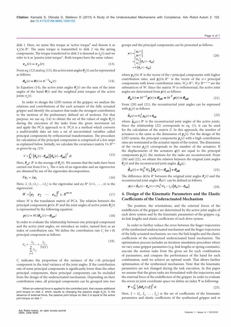
of the LDD is connected to a disk 1 (position 1). The angular position of disk 1 is determined by the signals coming from the LDD. Disk 1 is connected to a second disk (position 2) via two elastic elements, denoted as positions 3 and 4 respectively. Disk 2 is linked to the gripper joint and can change its angle θi(t). It is assumed that the transmission ratio between disk 2 and the joint is 1, i.e. disk 2 and the joint change with the same rotation angle. As shown in Figure 3, the finger joint angle θi(t) is the sum of the joint angle of disk 1 θai(t) and the joint angle θpi(t) caused by the deformations of the springs, i.e.
( ) ( ) ( )i ai pit t tθ θ θ= + (2)
For all drive systems of the gripper, the same relations can be presented in the following general form
(t) (t ) (t )θ θθ = +a p (3)
where θ(t) is the vector of all joint gripper angles, and θa(t) and θp(t) are the joint angles of disks 1 and 2 respectively and θp(t)∈Rn. In this paper, for simplicity we name θa as ‘active angle’ because it is directly connected to the output of the LDD. We refer to θp as a ‘passive angle’. If no external force is applied to the joint, the joint angles of the hand θ(t)∈Rn are equal to the joint angles determined by the LDD, i.e. θi(t) = θai(t). In this paper, we call the torques generated by the deformations of the springs “passive joint torques”. The passive joint torques τp(t)∈Rn are given as follows:
( ) ( )t K tp pτ θ= − (4).
Here, K=diag(k1, k2, … , kn) is a matrix of spring constants. ki (i = 1, … , n) have positive values.
3. Design and Optimization of the UnderactuatedMechanism
The proposed approach for synthesis of the gripper mechanism consists of three steps:
1. Initially, we design a fully actuated gripper structure that allowsthe completion of the tasks from the intended movement set.
Figure 1: An LDD example.
Figure 2: An example of a mechanism with r actuators and n LDDs.
Figure 3: Relationship among joint angles; a/without external force; b/ with external force.
Adv Robot Autom, an open access journal ISSN: 2168-9695
Citation: Kamada S, Obinata G, Stefanov D (2013) A Study of the Underactuated Mechanisms with Compliance. Adv Robot Autom 2: 102. doi:10.4172/2168-9695.1000102
Page 3 of 7
Volume 1 • Issue 4 • 1000102
2. Then, we minimize the number of the actuators by applyingPrincipal Component Analysis (PCA) [18,19].
3. Next, we reduce additionally the error between the fingertrajectory of the synthesized underactuated mechanism and thefinger trajectories of the fully actuated mechanism by varyingand optimizing the link lengths and the elastic coefficients ofthe synthesized underactuated hand mechanism.
3.1 System structure of the gripper
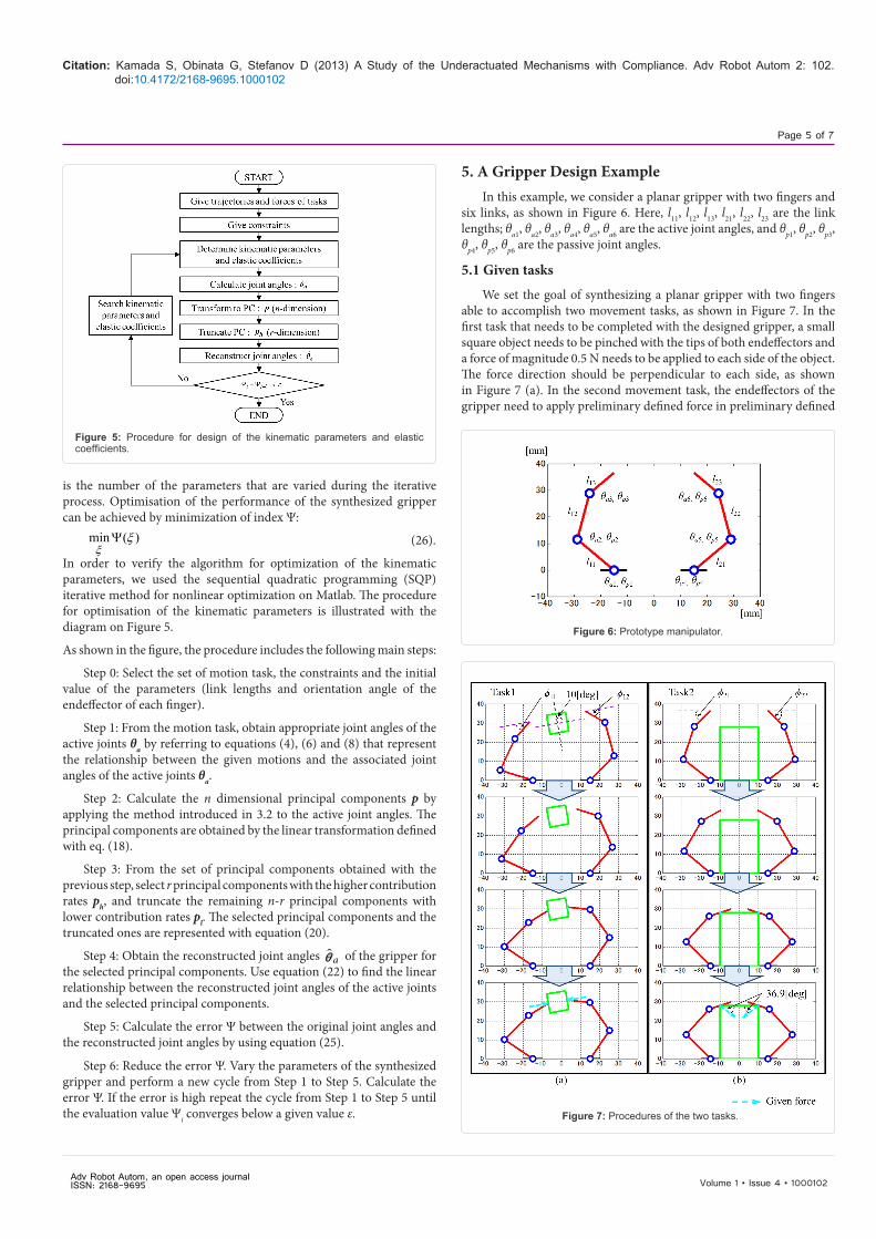
In order to explain the approach for the design of a gripper with elastic components for a given set of joint motions, we refer to the gripper structure shown in Figure 4. Here, for simplicity of the presentation, we consider a multi-joint planar gripper with two fingers that can move in the two dimensional plane and which contains revolute joints with one degree of freedom. However, the proposed method can be applied easily to artificial hands that operate in the three dimensional space. The gripper has n joints that are actuated by r actuators via n LDD systems and n elastic elements (n>r). The distal phalanges are named here as ‘endeffectors’ and on the figure they are denoted as positions 1 and 2.
The gripper should be able to accomplish a set of manipulation tasks with a group of rigid bodied objects of known size and shape. During each task, the distal phalanges of the multi-joint manipulator need to touch the object and to apply pre-defined forces to it. In Figure 4, these forces are denoted as F1 and F2. The forces are applied in contact points denoted with C1 and C2. It is assumed that there is no slippage between the fingers and the object surface during the task execution. The set of tasks that need to be accomplished with the gripper is given in advance. The synthesis of the gripper mechanism will include the composition of the LDD system that will be able to actuate fingers joints in a way to allow the completion of the task from the given set.
The given set of desired positions and orientations of the links and the preferred forces and torques are described with eq. (5).
≤≤∈∈
)0()()(
fh
h
ttRtRt
Fu
(5)
where u(t) is the h-dimensional vector of the positions and orientations of each finger segment during the execution of the tasks from the set, F(t) is the h-dimensional vector of the force and torque exercised by the endeffectors to the grasped object during the completion of the tasks, and t is the time. The given tasks start at time t=0 and end at t=tf. The dimension h depends on the type of the gripper (h=3 for a planar gripper and h=6 for grippers that operate in the three dimensional space). Since we control the position, the orientation, the force and the torque of the end point of an open kinematic structure with n joints, the dimension n of the joint coordinate space is higher than the dimension h of the task coordinate space. The position of the end effectors u(t) depends on the active angles θa(t)∈Rn, and the passive angles θp(t)∈Rn of all drive mechanisms of the same finger (see Figure 3) can be expressed on the following way:
( )(t ) f (t ), (t )a pu θ θ= (6).
The relation between the velocities of the end effectors and the joint angle velocities can be presented as follows:
( ) (t )(t ) (t ), (t )
(t )J
aa p
pu
θθ
θ θ
=
(7)
where J(θa(t), θp(t))∈Rh×2n is the Jacobian matrix. The relation between the joint torques and the external force acting to the same joint can be represented as follows:
( )T(t )J (t ), (t ) (t )(t )
aa p
pF
τθ θτ
=
(8)
where τa(t)∈Rn are the active joint torques and τp(t)∈Rn are the passive joint torques. The Jacobian matrix is divided as follows:
( ) ( ) ( )( ), ( ) ( ), ( ) ( ), ( )a pJ t t J t t J t ta p a p a pθ θ θ θ θ θ = (9)
where Ja∈Rh×n, Jp∈Rh×n are sub matrixes of J. Considering (9), the joint torques can be rewritten as follows:
( )( ) ( ), ( ) ( )T
at J t t ta a p Fτ θ θ= (10)
( )( ) ( ), ( ) ( )T
pt J t t tp a p Fτ θ θ= (11).
We use equations (6), (7), (10) and (11) to obtain the joint angles and the torque values as the function of t for each point of the movement trajectories and thus, to build the set of the variable values during the execution of the tasks from the given set.
3.2 LDD design by using Principal Component Analysis
The LDD parameters of the drive systems that actuate the gripper with elasticity can be defined by using the PCA approach [18,19]. PCA is a mathematical procedure which uses an orthogonal transformation to convert a multivariable original data set into a set of uncorrelated data sets called principal components. Principal components are synthesis variables of the original data sets. The transformation matrix of PCA is calculated by eigenvalue decomposition of a covariance matrix of original data set. Here, we follow a procedure which is similar to the procedure proposed in [17] for the design of the LDD of a gripper without elastic elements. Initially, it is assumed that the mechanism is fully actuated (i.e. n=r) and each joint of the mechanism is connected to an independent drive system with elasticity in which the structure is similar to the system shown in Figure 3. From eq. (3) and eq. (4), the active joint angles θa(t) can be represented as follows:
1( ) ( ) ( )t t K tθ θ τ−= +a p (12).
As illustrated with the structure in Figure 3, the torque on disk 1 is generated and controlled by the LDD that is directly connected with
n
r
elastic
multi-jointmanipulator
(n joints)
actuators
(n>r)
components
LDD system
1F1
C2C1
F2x
xy
y2
11
2
2
Figure 4: Framework of the gripper mechanism.
Adv Robot Autom, an open access journal ISSN: 2168-9695
Citation: Kamada S, Obinata G, Stefanov D (2013) A Study of the Underactuated Mechanisms with Compliance. Adv Robot Autom 2: 102. doi:10.4172/2168-9695.1000102
Page 4 of 7
Volume 1 • Issue 4 • 1000102
disk 1. Here, we name this torque as ‘active torque” and denote it as τa(t)∈Rn. The same torque is transmitted to disk 2 via the spring components. The torque transferred to disk 2 is denoted as τp(t) and we refer to it as ‘passive joint torque’1. Both torques have the same values:
( ) ( )a pt tτ τ= (13).
From eq. (12) and eq. (13), the active joint angles θa(t) can be represented as follows:
1( ) ( ) ( )t t K tθ θ τ−= +a a (14).
In Equation (14), the active joint angles θa(t) are the sum of the joint angles of the hand θ(t) and the weighted joint torques of the active joints τa(t).
In order to design the LDD system of the gripper, we analyze the relations and contributions of the each actuator of the fully actuated gripper and identify the actuators that make the strongest contribution to the motions of the preliminary defined set of motions. For that purpose, we use eq. (14) to obtain the set of the values of angle θa(t) during the execution of the tasks from the given movement set and apply the PCA approach to it. PCA is a method which converts a multivariable data set into a set of uncorrelated variables called principal components by orthonormal transformation. The procedure for calculation of the principal components is comprised of a few steps as explained below. Initially, we calculate the covariance matrix V∈Rn×n as given by eq. (15).
{ }{ }0 ( ) ( )ft TV t t dtθ θ θ θ= − −∫ a a0 a a0 (15)
Here, θa0∈Rn is the average of θa(t). We assume that the tasks have been carried out from 0 to tf. The n sets of an eigenvalue and an eigenvector are obtained by use of the eigenvalue decomposition.
iiV ee λ= (16)
Here, λi (λ1>λ2>…>λn) is the eigenvalue and ei∈Rn (i=1, … , n) is the eigenvector.
[ ] nnTn RW ×∈= eee 21 (17)
where W is the translation matrix of PCA. The relation between the principal components p(t)∈Rn and the joint angles of active joints θa(t) is represented by the following equation:
(t ) W{ (t ) }θ θ= −a a0p (18)
In order to evaluate the relationship between one principal component and the active joint angles, we introduce an index, named here as an index of contribution rate. We define the contribution rate Ci for i-th principal component as follows:
1
( )i i
i nj
j
CTr V
=
λ λ= =
λ∑
(19).
Ci indicates the proportion of the variance of the i-th principal component to the total variance of the joint angles. If the contribution rate of some principal components is significantly lower than the other principal components, these principal components can be excluded from the design of the underactuated mechanism. Depending on their contribution rates, all principal components can be grouped into two
groups and the principal components can be presented as follows:
{ }
{ }
h
l
(t )(t )
(t )
W(t )
W
W (t )
θ θ
θ θ
=
= −
= −
h
l
a a0
a a0
pp
p (20)
where ph(t)∈Rr is the vector of the r principal components with higher contribution rates, and pl(t)∈Rn-r is the vector of the n-r principal components with lower contribution rates, Wh∈Rrn, Wl∈R(n-r) ×n are the submatrices of W. Since the matrix W is orthonormal, the active joint angles are determined from p(t) as follows:
1( ) ( ) ( )Tt W t W tθ θ θ−= + = +a a0 a0p p (21).
From (20) and (21), the reconstructed joint angles can be expressed with ph(t) as follows:
( ) ( )Tht W tθ θ= +a h a0p (22)
where ( )tθ a ∈Rn is the reconstructed joint angles of the active joints. Since the relationship (22) corresponds to eq. (1), it can be used for the calculation of the matrix Z. In this approach, the number of actuators is the same as the dimension of ph(t). For the design of the LDD system, the principal components ph(t) with a high contribution rates are nominated as the actuator inputs of the system. The dimension of the vector ph(t) corresponds to the number of the actuators. If the displacements of the actuators q(t) are equal to the principal components ph(t), the motions for the tasks are reconstructed. From (20) and (22), we obtain the relation between the original joint anglesθa(t) and the reconstructed joint angles ( )tθ a : { }( ) ( )T
h ht W W tθ θ θ θ= − +a a a0 a0 (23).
The difference ∆(t)∈Rn between the original joint angles θa(t) and the reconstructed joint angles ( )tθ a can be defined as follows:
{ }( ) ( ) ( ) ( ) ( )Th h nt t t W W I t∆ θ θ θ θ= − = − −a a a a0 (24).
4. Design of the Kinematic Parameters and the ElasticCoefficients of the Underactuated Mechanism
The position, the orientations, and the external forces of the endeffectors of the gripper are determined by the active joint angles of each drive system and by the kinematic parameters of the gripper, e.g. its link lengths and elastic coefficients of each drive system.
In order to further reduce the error between the finger trajectories of the synthesized underactuated mechanism and the finger trajectories of the fully actuated mechanism, we vary the link lengths and the elastic coefficients of the synthesized underactuated hand mechanism. The optimisation process includes an iteration simulation procedure where we vary some gripper parameters (e.g. link lengths or spring constants), execute the motion tasks from the given set for each combination of parameters, and compare the performance of the hand for each combination, until we achieve an optimal result. That allows further optimisation of the synthesized mechanism. Note that the kinematic parameters are not changed during the task execution. In this paper we assume that the given tasks are formulated with the trajectories and the external force of the endeffectors of the gripper. In order to evaluate the errors in joint coordinate space we define an index Ψ as following:
20 ( ( ), )ft
t dtΨ θ ξ∆= ∫ a (25).
Here, ξ = (ξ1, ξ2, … , ξm) is the set of coefficients of the kinematic parameters and elastic coefficients of the synthesized gripper and m
1When an external force is applied to the controlled joint, that causes additional joint torque on disk 2, which results to changing the passive angle θpi(t). In the absence of external force, the passive joint torque on disk 2 is equal to the active joint torque on disk 1.
Adv Robot Autom, an open access journal ISSN: 2168-9695
Citation: Kamada S, Obinata G, Stefanov D (2013) A Study of the Underactuated Mechanisms with Compliance. Adv Robot Autom 2: 102. doi:10.4172/2168-9695.1000102
Page 5 of 7
Volume 1 • Issue 4 • 1000102
is the number of the parameters that are varied during the iterative process. Optimisation of the performance of the synthesized gripper can be achieved by minimization of index Ψ:
)(min ξξ
Ψ (26).
In order to verify the algorithm for optimization of the kinematic parameters, we used the sequential quadratic programming (SQP) iterative method for nonlinear optimization on Matlab. The procedure for optimisation of the kinematic parameters is illustrated with the diagram on Figure 5.
As shown in the figure, the procedure includes the following main steps:
Step 0: Select the set of motion task, the constraints and the initial value of the parameters (link lengths and orientation angle of the endeffector of each finger).
Step 1: From the motion task, obtain appropriate joint angles of the active joints θa by referring to equations (4), (6) and (8) that represent the relationship between the given motions and the associated joint angles of the active joints θa.
Step 2: Calculate the n dimensional principal components p by applying the method introduced in 3.2 to the active joint angles. The principal components are obtained by the linear transformation defined with eq. (18).
Step 3: From the set of principal components obtained with the previous step, select r principal components with the higher contribution rates ph, and truncate the remaining n-r principal components with lower contribution rates pl. The selected principal components and the truncated ones are represented with equation (20).
Step 4: Obtain the reconstructed joint angles aθ of the gripper for the selected principal components. Use equation (22) to find the linear relationship between the reconstructed joint angles of the active joints and the selected principal components.
Step 5: Calculate the error Ψ between the original joint angles and the reconstructed joint angles by using equation (25).
Step 6: Reduce the error Ψ. Vary the parameters of the synthesized gripper and perform a new cycle from Step 1 to Step 5. Calculate the error Ψ. If the error is high repeat the cycle from Step 1 to Step 5 until the evaluation value Ψi converges below a given value ε.
5. A Gripper Design ExampleIn this example, we consider a planar gripper with two fingers and
six links, as shown in Figure 6. Here, l11, l12, l13, l21, l22, l23 are the link lengths; θa1, θa2, θa3, θa4, θa5, θa6 are the active joint angles, and θp1, θp2, θp3, θp4, θp5, θp6 are the passive joint angles.
5.1 Given tasks
We set the goal of synthesizing a planar gripper with two fingers able to accomplish two movement tasks, as shown in Figure 7. In the first task that needs to be completed with the designed gripper, a small square object needs to be pinched with the tips of both endeffectors and a force of magnitude 0.5 N needs to be applied to each side of the object. The force direction should be perpendicular to each side, as shown in Figure 7 (a). In the second movement task, the endeffectors of the gripper need to apply preliminary defined force in preliminary defined
Figure 5: Procedure for design of the kinematic parameters and elastic coefficients.
Figure 6: Prototype manipulator.
Figure 7: Procedures of the two tasks.
Adv Robot Autom, an open access journal ISSN: 2168-9695
Citation: Kamada S, Obinata G, Stefanov D (2013) A Study of the Underactuated Mechanisms with Compliance. Adv Robot Autom 2: 102. doi:10.4172/2168-9695.1000102
Page 6 of 7
Volume 1 • Issue 4 • 1000102
directions to the upper edges of an object located between gripper fingers whose position is fixed in advance. The task is illustrated with Figure 7 (b). In the figure, the initial orientation angles of the finger tips are denoted as φ11, φ12, φ21, and φ22. The forces applied by gripper fingers to the object are shown as dashed line arrows. In this example, the parameters of the fully actuated gripper have the following values:
Lengths of the finger phalanges (lij):
11 12 13
21 22 23
18.0[ ], 18.0[ ], 12.0[ ]18.0[ ], 18.0[ ], 12.0[ ]
l mm l mm l mml mm l mm l mm
= = == = =
(27)
Initial orientation angles of the end effectors (φij):
11 12
21 22
40.0[deg], 40.0[deg]
45.0[deg], 45.0[deg]
= =
= =
φ φ
φ φ (28).
The spring constants of the drive system of each joint ki (i = 1, … ,6, j = 1, 2) are defined as follows:
]m/radN[0800.0],m/radN[0800.0]m/radN[0800.0],m/radN[0800.0]m/radN[0800.0],m/radN[0800.0
654321
⋅=⋅=⋅=⋅=⋅=⋅=
kkkkkk
(29).
During the completion of the movement tasks, the gripper tips need to move on a straight line to the contact points with the object. It is also required that the trajectory error and the force error between the fully actuated gripper and the synthesized underactuated gripper should not exceed 10%.
5.2 Gripper synthesis
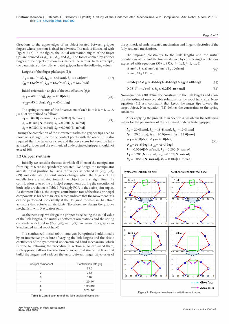
Initially, we consider the case in which all joints of the manipulator from Figure 6 are independently actuated. We design the manipulator and its initial position by using the values as defined in (27), (28), (29) and calculate the joint angles changes when the fingers of theendeffectors are moving toward the object on a straight line. Thecontribution rates of the principal components during the execution ofboth tasks are shown in Table 1. We apply PCA to the active joint angles.As shown in Table 1, the integral contribution rate of the first 3 principalcomponents is higher than 99%, which indicate that the movement taskcan be performed successfully if the designed mechanism has threeactuators that actuate all six joints. Therefore, we design the grippermechanism with 3 actuators only.
As the next step, we design the gripper by selecting the initial value of the link lengths, the initial endeffectors orientations and the spring constants as defined in (27), (28), and (29). We name this gripper as ‘synthesized initial robot hand’.
The synthesized initial robot hand can be optimised additionally by an interactive procedure of varying the link lengths and the elastic coefficients of the synthesized underactuated hand mechanism, which is done by following the procedure in section 4. As explained there, such approach allows the selection of an optimal size of the links that build the fingers and reduces the error between finger trajectories of
the synthesized underactuated mechanism and finger trajectories of the fully actuated mechanism.
The imposed constraints to the link lengths and the initial orientations of the endeffectors are defined by considering the relations expressed with equations (30) to (32), (i = 1, 2, j= 1, …, 6).
1 2
3
15[mm] 20[mm], 15[mm] 20[mm]12[mm] 15[mm]
i i
i
l ll
≤ ≤ ≤ ≤≤ ≤
(30)
1 2i30[deg] 45[deg], 45[deg] 60[deg]i≤ ≤ ≤ ≤φ φ (31)
0.05[N m / rad] 0.2[N m / rad]jk⋅ ≤ ≤ ⋅ (32)
Non-equations (30) define the constraint to the link lengths and allow the discarding of unacceptable solutions for the robot hand size. Non-equation (31) sets constraint that keeps the finger tips toward the target object. Non-equation (32) defines the constraints to the spring constants.
After applying the procedure in Section 4, we obtain the following values for the parameters of the optimised underactuated gripper:
11 12 13
21 22 23
11 12
21 22
1 2
3 4
20.0[ ], 18.4[ ], 15.0[ ]20.0[ ], 20.0[ ], 12.0[ ]45.0[deg], 45.0[deg]
56.8[deg], 45.0[deg]0.0566[N m/rad], 0.200[N m/rad]0.200[N m/rad], 0.137[N m/rad
l mm l mm l mml mm l mm l mm
k kk k
= = == = == =
= == ⋅ = ⋅= ⋅ = ⋅
φ φ
φ φ
5 6
]0.0565[N m/rad], 0.104[N m/rad]k k= ⋅ = ⋅
(33).
Figure 8: Designed mechanism with three actuators.
Principal component Contribution rate [%]1 73.52 24.53 1.824 1.22×10⁻¹
5 1.05×10⁻²
6 5.71×10⁻⁴
Table 1: Contribution rate of the joint angles of two tasks.
Adv Robot Autom, an open access journal ISSN: 2168-9695
Citation: Kamada S, Obinata G, Stefanov D (2013) A Study of the Underactuated Mechanisms with Compliance. Adv Robot Autom 2: 102. doi:10.4172/2168-9695.1000102
Page 7 of 7
Volume 1 • Issue 4 • 1000102
The underactuated gripper synthesized by using the parameters from eq. (33) is called here the ‘synthesized optimal robot hand’.
As a next step, we compare the motions of the synthesized initial robot hand and the synthesized optimal robot hand for the completion of the movement tasks defined in 5.1. Figure 8 shows the initial and the end positions of the initial robot hand and the designed robot hand during the completion of the tasks. In this figure, the given forces are shown as dashed line arrows. The straight line arrows indicate the forces that the synthesized optimal robot hand will apply to the target object.
In order to evaluate the error between the given force and the force that the underactuated robot hand applies to the object, we use force evaluation indexes for the left and the right finger, noted here as El and Er respectively and expressed as follow:
100[%]
100[%]
l
r
E
E
−= ×
−= ×
gl al
gl
gr ar
gr
f f
f
f f
f
(34).
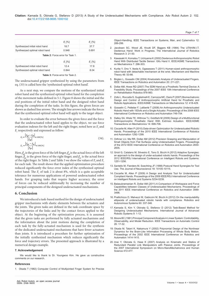
Here, fgl is the given force of the left finger, fal is the actual force of the left finger, fgr is the given force of the right finger, and far is the actual force of the right finger. In Table 2 and Table 3 we show the values of El and Er for each task. The result shows that the applied optimization procedure reduced significantly the force error index of the synthesized optimal robot hand. The Er of task 2 is about 8%, which is a quite acceptable tolerance for numerous applications of powered underactuated robot hands. For grasping tasks that require higher accuracy, the error of forces can be reduced additionally by increasing the number of principal components of the designed underactuated mechanisms.
6. ConclusionWe introduced a task-based method for the design of underactuated
gripper mechanisms with elastic elements between the actuators and the joints. The given tasks are defined in the task coordinate space by the trajectories of the links and by the contact forces applied to the object. At the beginning of the optimization process, it is assumed that the given tasks are performed by fully actuated mechanisms and the information about the joint motions during the completion of each task by the fully-actuated mechanism is used for the synthesis of the dedicated underactuated mechanisms that have fewer actuators than joints. It is introduced a procedure for further optimization of the initially synthesized mechanism which reduces significantly the force and trajectory errors. The presented approach is illustrated by a numerical design example.
7. Acknowledgement
We would like to thank to Dr. Youngwoo Kim. He gave us constructive comments on our research.
References1. Okada T (1982) Computer Control of Multijointed Finger System for Precise
Object-Handling. IEEE Transactions on Systems, Man, and Cybernetics 12: 289-299.
2. Jacobsen SC, Wood JE, Knutti DF, Biggers KB (1984) The UTAH/M.I.T. Dexterous Hand: Work in Progress. The International Journal of Robotics Research 3: 21-50.
3. Kawasaki H, Komatsu T, Uchiyama K (2002) Dexterous Anthropomorphic Robot Hand With Distributed Tactile Sensor: Gifu Hand II. IEEE/ASME Transactions on Mechatronics 7: 296-303.
4. Kurita Y, Ono Y, Ikeda A, Ogasawara T (2011) Human-sized anthropomorphic robot hand with detachable mechanism at the wrist. Mechanism and Machine Theory 46: 53-66.
5. Birglen L, Gosselin CM (2004) Kinetostatic Analysis of Underactuated Fingers. IEEE Transactions on Robotics and Automation 20: 211-221.
6. Dollar AM, Howe RD (2007) The SDM Hand as a Prosthetic Terminal Device: A Feasibility Study. Proceedings of the 2007 IEEE 10th International Conference on Rehabilitation Robotics 978-983.
7. Zollo L, Roccella S, Guglielmelli E, Carrozza MC, Dario P (2007) Biomechatronic Design and Control of Anthropomorphic Artificial Hand for Prosthetic and Robotic Applications. IEEE/ASME Transactions on Mechatronics 12: 418-429.
8. Gosselin C, Pelletier F, Laliberté T (2008) An Anthropomorphic Underactuated Robotic Hand with 15Dofs and a Single Actuator. Proceedings of the 2008 IEEE International Conference on Robotics and Automation 749-754.
9. Dalley SA, Wiste TE, Withrow TJ, Goldfarb M (2009) Design of a Multifunctional Anthropomorphic Prosthetic Hand With Extrinsic Actuation. IEEE/ASME Transactions on Mechatronics 14: 699-706.
10. Ciocarlie M, Allen P (2010) Data-driven Optimization for Underactuated Robotic Hands. Proceedings of the 2010 IEEE International Conference of Robotics and Automation 1292-1299.
11. Odhner LU, Ma RR, Dollar AM (2012) Precision Grasping and Manipulation of Small Objects from Flat Surfaces using Underactuated Fingers. Proceedings of the 2012 IEEE International Conference on Robotics and Automation 2830-2835.
12. Grioli G, Catalano M, Silvestro E, Tono S, Bicchi A (2012) Adaptive Synergies: an approach to the design of under-actuated robotic hands. Proceedings of the 2012 IEEE/RSJ International Conference on Intelligent Robots and Systems: 1251-1256.
13. Santello M, Flanders M, Soechting JF (1998) Postural Hand Synergies for Tool Use. The Journal of Neuroscience 18: 10105-10115.
14. Ciocarlie M, Allen P (2009) A Design and Analysis Tool for Underactuated Compliant Hands. Proceedings of the 2009 IEEE/RSJ International Conference on Intelligent Robots and Systems 5234-5239.
15. Balasubramanian R, Dollar AM (2011) A Comparison of Workspace and Force Capabilities between Classes of Underactuated Mechanisms. Proceedings of the 2011 IEEE International Conference on Robotics and Automation 3489-3496.
16. Prattichizzo D, Malvezzi M, Gabiccini M, Bicchi A (2012) On the manipulability ellipsoids of underactuated robotic hands with compliance. Robotics and Autonomous Systems 60: 337-346.
17. Kamada S, Kim Y, Obinata G, Stefanov D (2012) Task-Based Method for Designing Underactuated Mechanisms. International Journal of Advanced Robotic Systems 9: 1-12.
18. Moore BC (1981) Principal Component Analysis in Linear System: Controllability, Observability, and Model Reduction. IEEE Transactions on Automatic Control 26: 17-32.
19. Okada M, Tatani K, Nakamura Y (2002) Polynomial Design of the Nonlinear Dynamics for the Brain-Like Information Processing of Whole Body Motion. Proceedings of the 2002 IEEE International Conference on Robotics and Automation 1414-1415.
20. Imai Y, Obinata G, Hase K (2007) Analysis on Kinematic and Statics of Redundant Parallel Link Manipulators with Passive Joints. Proceedings of the 2007 International Symposium on Micro-NanoMechatronics and Human Science 472-477.
El [%] Er [%]
Synthesized initial robot hand 18.7 37.7Synthesized optimal robot hand 0.948 0.691
Table 2: Force error for Task 1.
El [%] Er [%]
Synthesized initial robot hand 12.4 17.8Synthesized optimal robot hand 0.844 8.04
Table 3: Force error for Task 2.
Adv Robot Autom, an open access journal ISSN: 2168-9695