Embed Size (px)
Citation preview
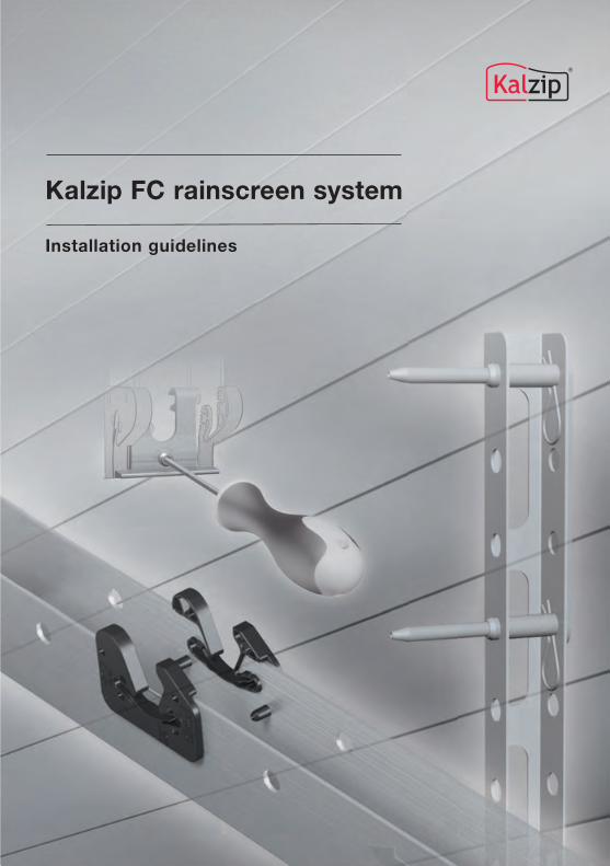
Kalzip FC rainscreen system
Installation guidelines

2
3
1.0 Introduction1.0 Introduction 4
2.0 System overview2.0 System overview 6
3.0 Transport, storage and handling3.0 Transport, storage and handling 12
4.0 General information 144.1 Sub-construction requirements 154.2 Panel support requirements 20
5.0 Sub-construction installation 245.1 Mono-click brackets on vertical rails 265.2 Modular click rail NE on vertical rails 285.3 Modular click rail SEL on L-brackets 305.4 Modular click rail SE on U-brackets 325.5 Modular click rail SE on horizontal rails 345.6 Modular click rail SE on structural cassette 365.7 Modular click rail setting out tool 38
6.0 Horizontal panel installation 436.1 Panel installation (bottom to top) 446.2 Panel installation (top to bottom) 486.3 Vertical panel joints 506.4 Fixed points 526.5 Adjustment of panel position 546.6 Corner panels 57
7.0 Flashing installation7.0 Flashing installation 61
8.0 Individual panel replacement8.0 Individual panel replacement 63
Overview Page
Contents
4
This installation manual specifies thecorrect methods for installing the KalzipFC rainscreen system, including supportelements, panels and accessories. Itshould be read together with the tech-nical approval document ZulassungZ-14.1-581 (June 2010). It should alsobe used in conjunction with all otherapplicable technical approvals, stand-ards and safe working procedures onthe construction site.
Installation of the Kalzip FC rainscreen iscarried out using proprietary systemsupport rails fixed to an adjustable sub-construction suitable for rainscreens.The chosen sub-construction must becapable of accommodating buildingtolerances to achieve a plane surfacein accordance with the specificationsgiven in this manual.
The manual contains general informa-tion about the FC rainscreen system andits components together with detaileddrawings and explanatory text for instal-lation. The drawings are not to scaleand therefore should not be dimen-sioned. Where appropriate, drawingsare labelled with metric dimensions.
Care has been taken to ensure that theinformation contained within this man-ual is correct. At the time of going topress, the diagrams and descriptionsrepresent our current knowledge of bestpractice. They are intended as rules forstandard applications and do not nec-essarily apply in all situations. Otherrelevant valid standards and local leg-islative requirements must also be takeninto account.
Suggestions for or descriptions of theend use or application of products ormethods of working are for informationonly and Kalzip accepts no liability inrespect thereof. Before using informa-tion or products supplied or manufac-tured by Kalzip the user should satisfyhimself that they are suitable for theirintended purpose.
Due to the dynamic nature of productdevelopment and continuous technicalimprovement, Kalzip reserves the rightto make amendments to the installationinstructions and technical specificationsgiven at any time without prior notice.Users should therefore check that theyhave the latest available edition of thismanual.
September 2011
1.0 Introduction
Introduction

5
Introduction
6
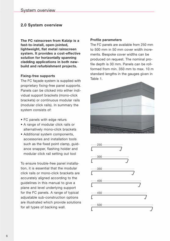
The FC rainscreen from Kalzip is afast-to-install, open-jointed,lightweight, flat metal rainscreensystem. It provides a cost-effectivesolution for horizontally spanningcladding applications in both new-build and refurbishment projects.
Fixing-free supportsThe FC façade system is supplied withproprietary fixing-free panel supports.Panels can be clicked into either indi-vidual support brackets (mono-clickbrackets) or continuous modular rails(modular click rails). In summary thesystem consists of:
• FC panels with edge returs• A range of modular click rails or
alternatively mono-click brackets• Additional system components,
accessories and installation toolssuch as the fixed point clamp, guid-ance snapper, flashing holder andmodular click rail setting out tool
To ensure trouble-free panel installa-tion, it is essential that the modularclick rails or mono-click brackets areaccurately aligned according to theguidelines in this manual to give aplane and level underlying supportfor the FC panels. A range of typicaladjustable sub-construction optionsare illustrated which provide solutionsfor all types of backing wall.
Profile parametersThe FC panels are available from 250 mmto 500 mm in 50 mm cover width incre-ments. Bespoke cover widths can beproduced on request. The nominal pro-file depth is 30 mm. Panels can be roll-formed from min. 350 mm to max. 10 mstandard lengths in the gauges given inTable 1.
System overview
2.0 System overview
250
300
350
400
450
500
7
Tabelle 1: FC panel thickness and cover width availability
Thickness(mm) FC 30/250 FC 30/300 FC 30/350 FC 30/400 FC 30/450 FC 30/500
1.0 – –
1.2
Available as standard Available on request – Not available
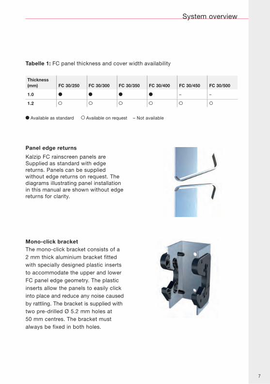
Panel edge returns
Kalzip FC rainscreen panels areSupplied as standard with edgereturns. Panels can be suppliedwithout edge returns on request. Thediagrams illustrating panel installationin this manual are shown without edgereturns for clarity.
Mono-click bracketThe mono-click bracket consists of a2 mm thick aluminium bracket fittedwith specially designed plastic insertsto accommodate the upper and lowerFC panel edge geometry. The plasticinserts allow the panels to easily clickinto place and reduce any noise causedby rattling. The bracket is supplied withtwo pre-drilled Ø 5.2 mm holes at50 mm centres. The bracket mustalways be fixed in both holes.
System overview
8
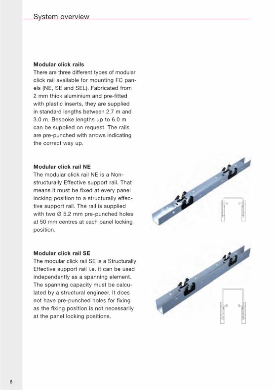
Modular click railsThere are three different types of modularclick rail available for mounting FC pan-els (NE, SE and SEL). Fabricated from2 mm thick aluminium and pre-fittedwith plastic inserts, they are suppliedin standard lengths between 2.7 m and3.0 m. Bespoke lengths up to 6.0 mcan be supplied on request. The railsare pre-punched with arrows indicatingthe correct way up.
Modular click rail NEThe modular click rail NE is a Non-structurally Effective support rail. Thatmeans it must be fixed at every panellocking position to a structurally effec-tive support rail. The rail is suppliedwith two Ø 5.2 mm pre-punched holesat 50 mm centres at each panel lockingposition.
Modular click rail SEThe modular click rail SE is a StructurallyEffective support rail i.e. it can be usedindependently as a spanning element.The spanning capacity must be calcu-lated by a structural engineer. It doesnot have pre-punched holes for fixingas the fixing position is not necessarilyat the panel locking positions.
System overview
9
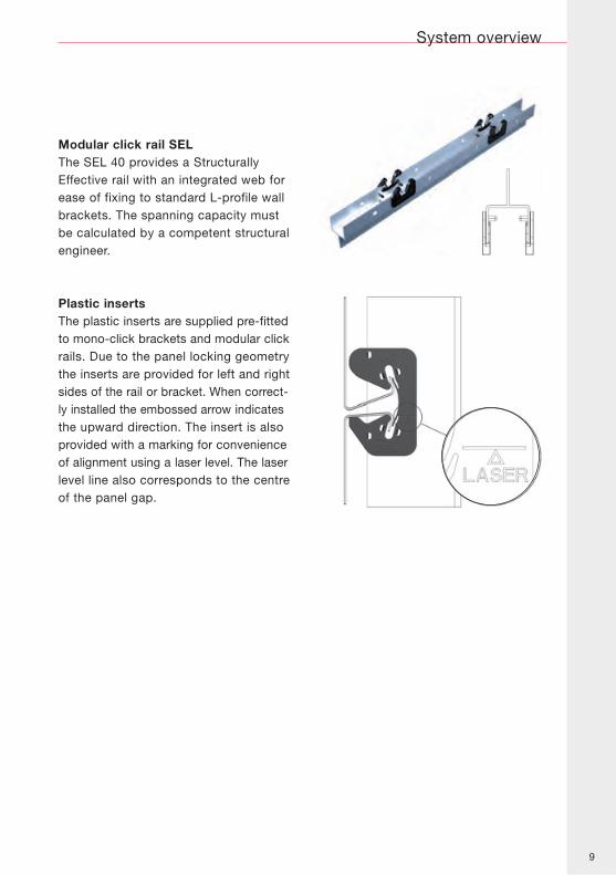
Modular click rail SELThe SEL 40 provides a StructurallyEffective rail with an integrated web forease of fixing to standard L-profile wallbrackets. The spanning capacity mustbe calculated by a competent structuralengineer.
Plastic insertsThe plastic inserts are supplied pre-fittedto mono-click brackets and modular clickrails. Due to the panel locking geometrythe inserts are provided for left and rightsides of the rail or bracket. When correct-ly installed the embossed arrow indicatesthe upward direction. The insert is alsoprovided with a marking for convenienceof alignment using a laser level. The laserlevel line also corresponds to the centreof the panel gap.
System overview
10
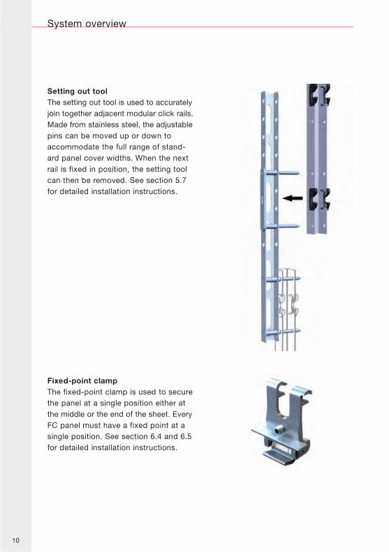
Setting out toolThe setting out tool is used to accuratelyjoin together adjacent modular click rails.Made from stainless steel, the adjustablepins can be moved up or down toaccommodate the full range of stand-ard panel cover widths. When the nextrail is fixed in position, the setting toolcan then be removed. See section 5.7for detailed installation instructions.
Fixed-point clampThe fixed-point clamp is used to securethe panel at a single position either atthe middle or the end of the sheet. EveryFC panel must have a fixed point at asingle position. See section 6.4 and 6.5for detailed installation instructions.
System overview
11
System overview
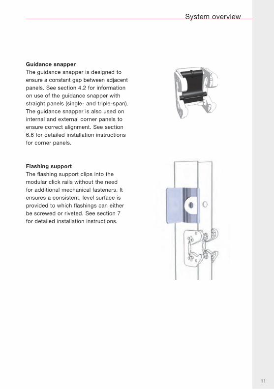
Guidance snapperThe guidance snapper is designed toensure a constant gap between adjacentpanels. See section 4.2 for informationon use of the guidance snapper withstraight panels (single- and triple-span).The guidance snapper is also used oninternal and external corner panels toensure correct alignment. See section6.6 for detailed installation instructionsfor corner panels.
Flashing supportThe flashing support clips into themodular click rails without the needfor additional mechanical fasteners. Itensures a consistent, level surface isprovided to which flashings can eitherbe screwed or riveted. See section 7for detailed installation instructions.
12
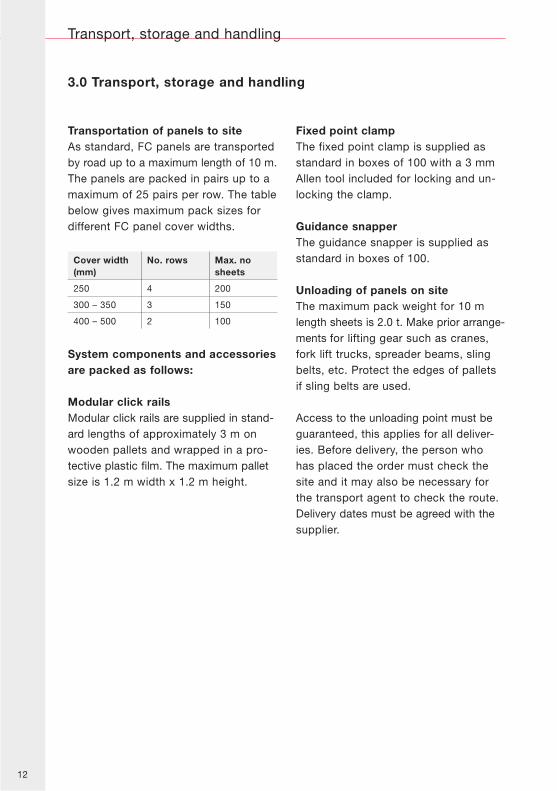
Transportation of panels to siteAs standard, FC panels are transportedby road up to a maximum length of 10 m.The panels are packed in pairs up to amaximum of 25 pairs per row. The tablebelow gives maximum pack sizes fordifferent FC panel cover widths.
Cover width(mm)
No. rows Max. nosheets
250 4 200
300 – 350 3 150
400 – 500 2 100
System components and accessoriesare packed as follows:
Modular click railsModular click rails are supplied in stand-ard lengths of approximately 3 m onwooden pallets and wrapped in a pro-tective plastic film. The maximum palletsize is 1.2 m width x 1.2 m height.
Fixed point clampThe fixed point clamp is supplied asstandard in boxes of 100 with a 3 mmAllen tool included for locking and un-locking the clamp.
Guidance snapperThe guidance snapper is supplied asstandard in boxes of 100.
Unloading of panels on siteThe maximum pack weight for 10 mlength sheets is 2.0 t. Make prior arrange-ments for lifting gear such as cranes,fork lift trucks, spreader beams, slingbelts, etc. Protect the edges of palletsif sling belts are used.
Access to the unloading point must beguaranteed, this applies for all deliver-ies. Before delivery, the person whohas placed the order must check thesite and it may also be necessary forthe transport agent to check the route.Delivery dates must be agreed with thesupplier.
Transport, storage and handling
3.0 Transport, storage and handling
13
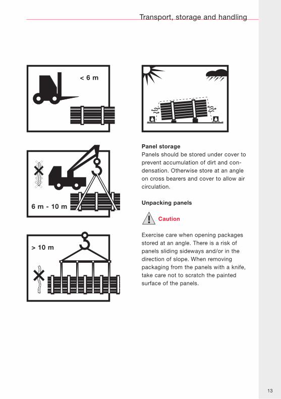
Panel storagePanels should be stored under cover toprevent accumulation of dirt and con-densation. Otherwise store at an angleon cross bearers and cover to allow aircirculation.
Unpacking panels
Caution
Exercise care when opening packagesstored at an angle. There is a risk ofpanels sliding sideways and/or in thedirection of slope. When removingpackaging from the panels with a knife,take care not to scratch the paintedsurface of the panels.
Transport, storage and handling
<6m< 6 m
>10m
>6m6 m - 10 m
> 10 m
14
General information
4.0 General information
Panel protective filmFC panels are supplied with a protectivepolyethylene film. This should be pee-led back from all panel edges beforeinstallation. The film can be temporarilykept on the panels to protect them fromcontamination from other works. In anycase the film should be removed com-pletely within three weeks of installa-tion.
Checking incoming materialsObtain confirmation of any material andpackaging deficiencies from the forwar-der and notify the supplier immediately.
Check that the number of packages andtheir contents agree with the deliverydocuments. Inform the supplierimmediately of any discrepancies indimensions or quantities etc.
Any damage occurring during transportmust be reported before installation.Claims for damaged goods will not beaccepted after installation.
All claims must be made within one
week of arrival on the building site.
Panel handlingSuitable protective gloves should alwaysbe worn when handling FC panels. Whencarrying individual panels on-site, makesure to keep them in an upright position.
Before commencing with installationof the FC rainscreen system, thischapter should be read in its entirety.It contains two sections giving keyinformation on sub-constructiontolerances and panel supportrequirements which applies to allsub-construction variations and panelcover widths
.
15
Installation of the Kalzip FCrainscreen system is achieved incombination with a suitable sub-construction system (see section 5).The sub-construction system mustbe capable of accommodatingbuilding tolerances to ensure that thesupporting elements are plane andlevel to within the tolerances given inthis section.These requirements are divided intoa number of specific criteria, all ofwhich must be met.
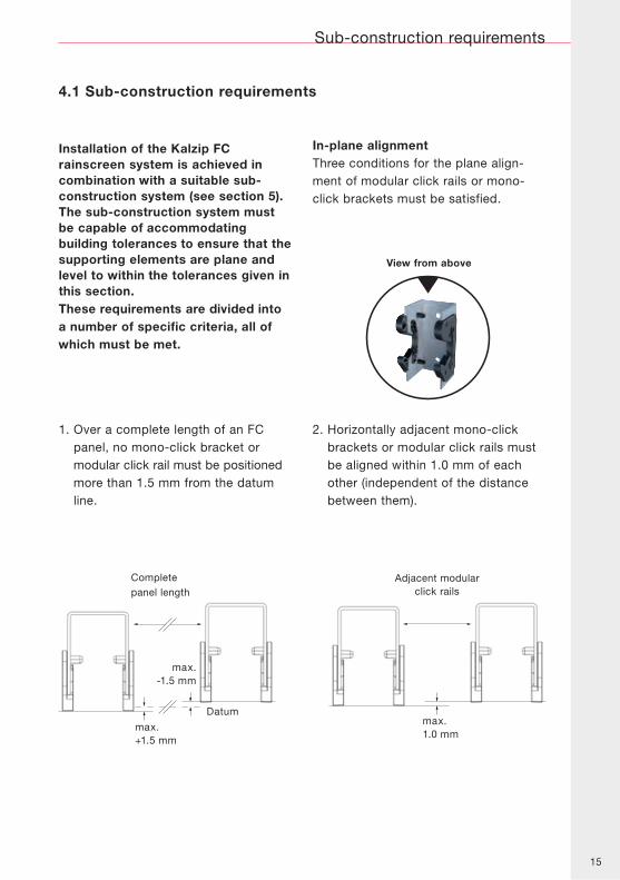
1. Over a complete length of an FCpanel, no mono-click bracket ormodular click rail must be positionedmore than 1.5 mm from the datumline.
In-plane alignmentThree conditions for the plane align-ment of modular click rails or mono-click brackets must be satisfied.
2. Horizontally adjacent mono-clickbrackets or modular click rails mustbe aligned within 1.0 mm of eachother (independent of the distancebetween them).
Sub-construction requirements
4.1 Sub-construction requirements
Completepanel length
Adjacent modularclick rails
max.1.0 mm
View from above
max.+1.5 mm
max.-1.5 mm
Datum
16
Sub-construction requirements
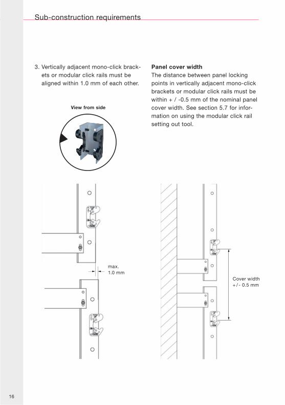
3. Vertically adjacent mono-click brack-ets or modular click rails must bealigned within 1.0 mm of each other.
Panel cover widthThe distance between panel lockingpoints in vertically adjacent mono-clickbrackets or modular click rails must bewithin + / -0.5 mm of the nominal panelcover width. See section 5.7 for infor-mation on using the modular click railsetting out tool.
max.1.0 mm
Cover width+ / - 0.5 mm
View from side
17
max.+1.5 mm
max.-1.5 mm
Completepanel length
max. 1.0 mm
Adjacent modularclick rails
Sub-construction requirements
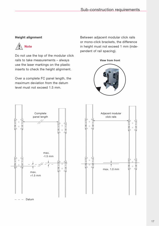
Height alignment
Note
Do not use the top of the modular clickrails to take measurements – alwaysuse the laser markings on the plasticinserts to check the height alignment.
Over a complete FC panel length, themaximum deviation from the datumlevel must not exceed 1.5 mm.
Between adjacent modular click railsor mono-click brackets, the differencein height must not exceed 1 mm (inde-pendent of rail spacing).
Datum
View from front
18
Sub-construction requirements
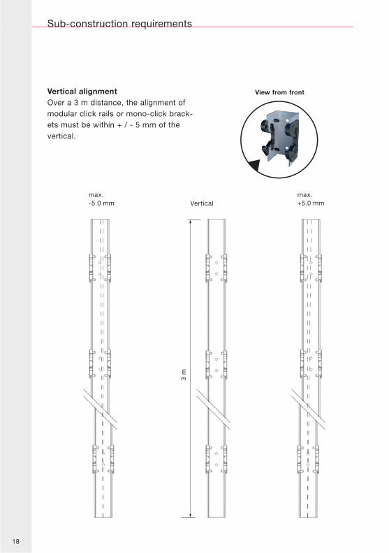
Vertical alignmentOver a 3 m distance, the alignment ofmodular click rails or mono-click brack-ets must be within + / - 5 mm of thevertical.
max.-5.0 mm
max.+5.0 mmVertical
3 m
View from front
19
max.1.0 mm 1.5 m Gliding point
Fixed point incentre of uppermodular click rail
Fixed point incentre of lowermodular click rail
Gliding point
1.5 m
Sub-construction requirements
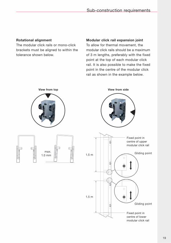
Rotational alignmentThe modular click rails or mono-clickbrackets must be aligned to within thetolerance shown below.
Modular click rail expansion jointTo allow for thermal movement, themodular click rails should be a maximumof 3 m lengths, preferably with the fixedpoint at the top of each modular clickrail. It is also possible to make the fixedpoint in the centre of the modular clickrail as shown in the example below.
View from top View from side
20
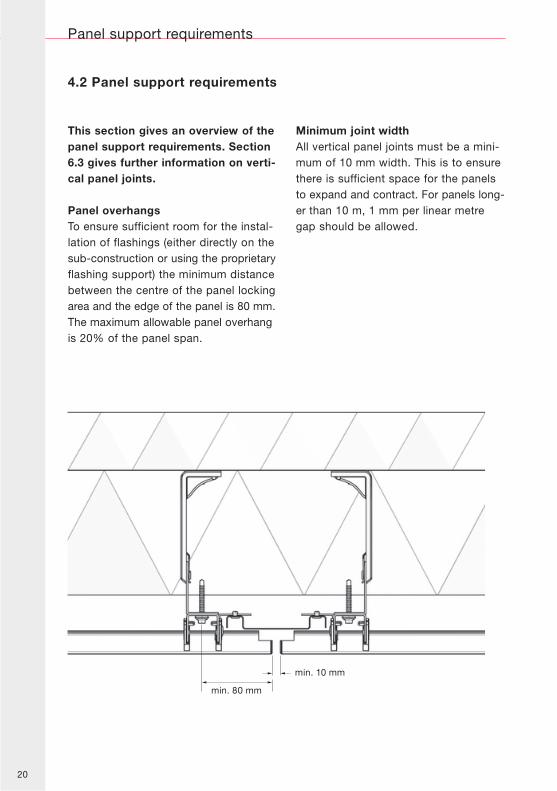
This section gives an overview of thepanel support requirements. Section6.3 gives further information on verti-cal panel joints.
Panel overhangsTo ensure sufficient room for the instal-lation of flashings (either directly on thesub-construction or using the proprietaryflashing support) the minimum distancebetween the centre of the panel lockingarea and the edge of the panel is 80 mm.The maximum allowable panel overhangis 20% of the panel span.
Minimum joint widthAll vertical panel joints must be a mini-mum of 10 mm width. This is to ensurethere is sufficient space for the panelsto expand and contract. For panels long-er than 10 m, 1 mm per linear metregap should be allowed.
4.2 Panel support requirements
Panel support requirements
min. 10 mm
min. 80 mm
21
Stop
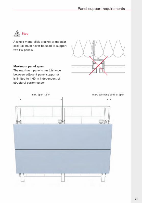
A single mono-click bracket or modularclick rail must never be used to supporttwo FC panels.
Maximum panel spanThe maximum panel span (distancebetween adjacent panel supports)is limited to 1.60 m independent ofstructural performance.
Panel support requirements
max. span 1.6 m max. overhang 20 % of span
22
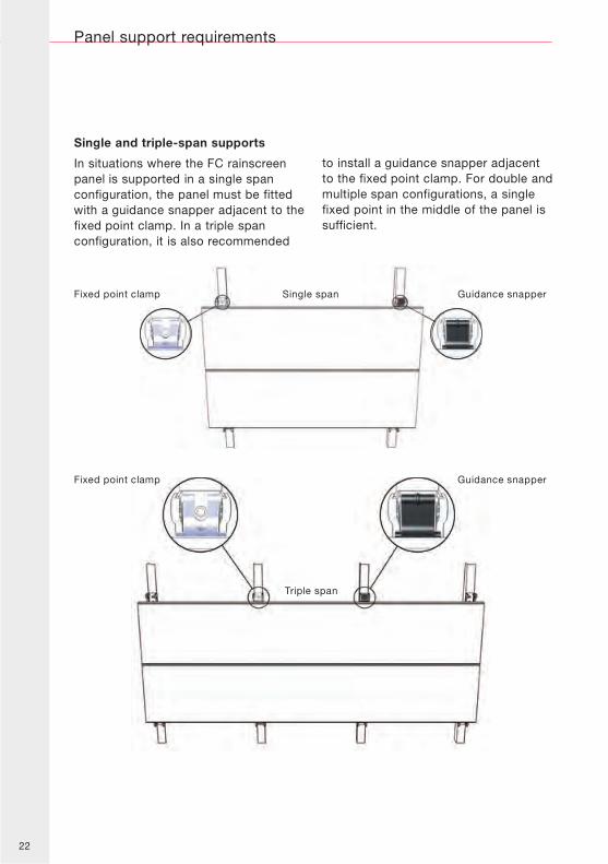
Single and triple-span supports
In situations where the FC rainscreenpanel is supported in a single spanconfiguration, the panel must be fittedwith a guidance snapper adjacent to thefixed point clamp. In a triple spanconfiguration, it is also recommended
to install a guidance snapper adjacentto the fixed point clamp. For double andmultiple span configurations, a singlefixed point in the middle of the panel issufficient.
Panel support requirements
Single span Guidance snapperFixed point clamp
Triple span
Guidance snapperFixed point clamp
23
Panel support requirements
Fixed pointclamp
Guidancesnapper
min. 10 mm
min. 150 mm, max. 1000 mm
min. 80 mm, max. 100 mm
min
. 3
00
mm
, m
ax.
20
00
mm
min
. 80
mm
, m
ax.
10
0 m
mm
in.
80 m
m,
ma
x. 1
00
mm
Guidancesnapper
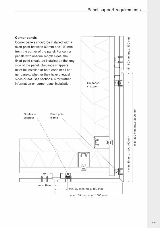
Corner panelsCorner panels should be installed with afixed point between 80 mm and 100 mmfrom the corner of the panel. For cornerpanels with unequal length sides, thefixed point should be installed on the longside of the panel. Guidance snappersmust be installed at both ends of all cor-ner panels, whether they have unequalsides or not. See section 6.6 for furtherinformation on corner panel installation.
24
Sub-construction installation
5.0 Sub-construction installation
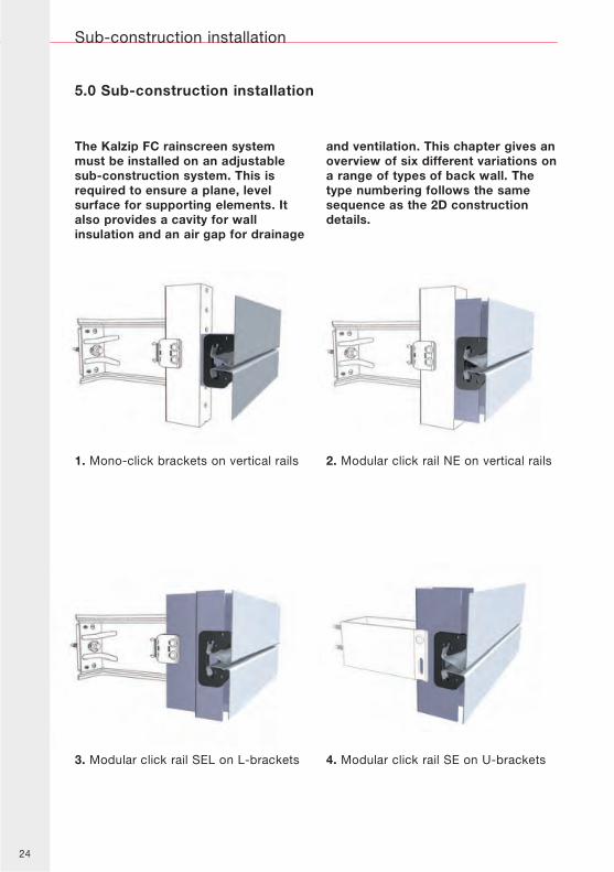
1. Mono-click brackets on vertical rails 2. Modular click rail NE on vertical rails
3. Modular click rail SEL on L-brackets 4. Modular click rail SE on U-brackets
The Kalzip FC rainscreen systemmust be installed on an adjustablesub-construction system. This isrequired to ensure a plane, levelsurface for supporting elements. Italso provides a cavity for wallinsulation and an air gap for drainage
and ventilation. This chapter gives anoverview of six different variations ona range of types of back wall. Thetype numbering follows the samesequence as the 2D constructiondetails.
25
Sub-construction installation
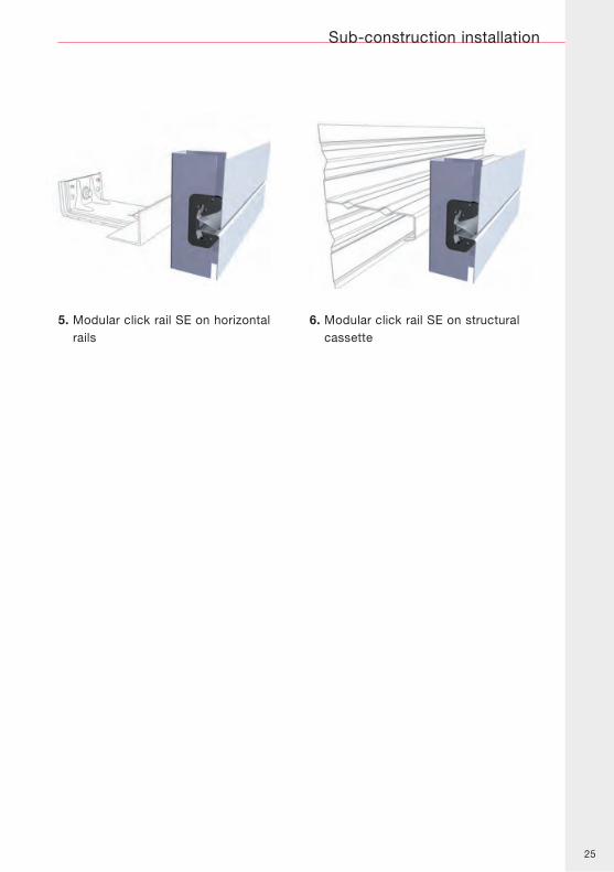
5. Modular click rail SE on horizontalrails
6. Modular click rail SE on structuralcassette
26
Mono-click brackets on vertical rails
5.1 Mono-click brackets on vertical rails
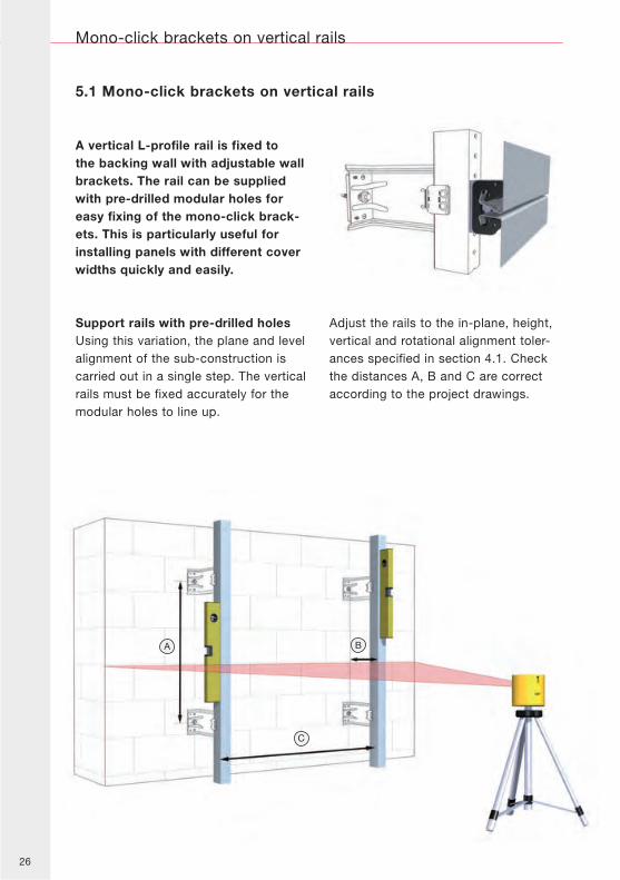
A vertical L-profile rail is fixed tothe backing wall with adjustable wallbrackets. The rail can be suppliedwith pre-drilled modular holes foreasy fixing of the mono-click brack-ets. This is particularly useful forinstalling panels with different coverwidths quickly and easily.
Support rails with pre-drilled holesUsing this variation, the plane and levelalignment of the sub-construction iscarried out in a single step. The verticalrails must be fixed accurately for themodular holes to line up.
Adjust the rails to the in-plane, height,vertical and rotational alignment toler-ances specified in section 4.1. Checkthe distances A, B and C are correctaccording to the project drawings.
27
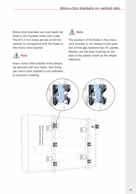
Mono-click brackets can now easily befixed in the modular holes with rivets.The Ø 5.2 mm holes are set at 50 mmcentres to correspond with the holes inthe mono-click bracket.
Note
Every mono-click bracket must alwaysbe secured with two rivets. One fixingper mono-click bracket is not sufficientto prevent it rotating.
Note
The position of the holes in the mono-click bracket is not related to the posi-tion of the gap between two FC panels.Always use the laser marking on theside of the plastic insert as the heightreference.
Mono-click brackets on vertical rails
Pan
el c
ove
r w
idth
28
Modular click rail NE on vertical rails
5.2 Modular click rail NE on vertical rails
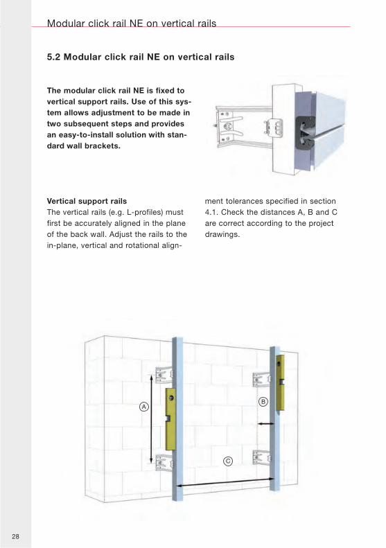
The modular click rail NE is fixed tovertical support rails. Use of this sys-tem allows adjustment to be made intwo subsequent steps and providesan easy-to-install solution with stan-dard wall brackets.
Vertical support railsThe vertical rails (e.g. L-profiles) mustfirst be accurately aligned in the planeof the back wall. Adjust the rails to thein-plane, vertical and rotational align-
ment tolerances specified in section4.1. Check the distances A, B and Care correct according to the projectdrawings.
29
Modular click rail NE on vertical rails
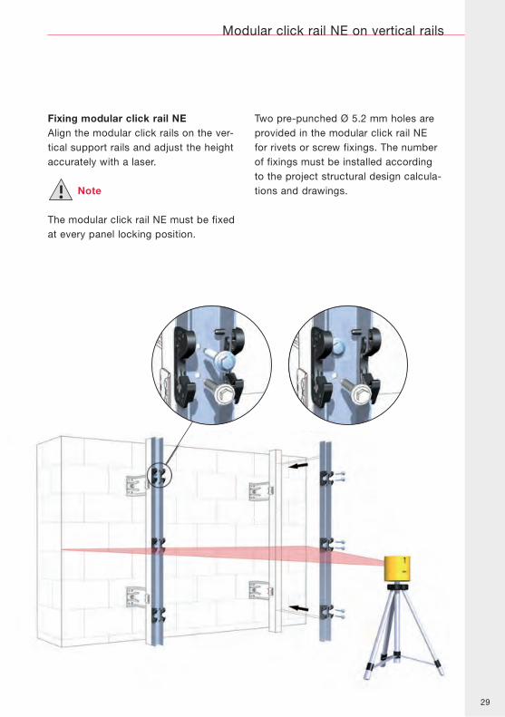
Fixing modular click rail NEAlign the modular click rails on the ver-tical support rails and adjust the heightaccurately with a laser.
Note
The modular click rail NE must be fixedat every panel locking position.
Two pre-punched Ø 5.2 mm holes areprovided in the modular click rail NEfor rivets or screw fixings. The numberof fixings must be installed accordingto the project structural design calcula-tions and drawings.
30
Modular click rail SEL on L-brackets
5.3 Modular click rail SEL on L-brackets
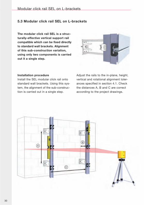
The modular click rail SEL is a struc-turally-effective vertical support railcompatible which can be fixed directlyto standard wall brackets. Alignmentof this sub-construction variation,using only two components is carriedout it a single step.
Installation procedureInstall the SEL modular click rail ontostandard wall brackets. Using this sys-tem, the alignment of the sub-construc-tion is carried out in a single step.
Adjust the rails to the in-plane, height,vertical and rotational alignment toler-ances specified in section 4.1. Checkthe distances A, B and C are correctaccording to the project drawings.
31
Modular click rail SEL on L-brackets
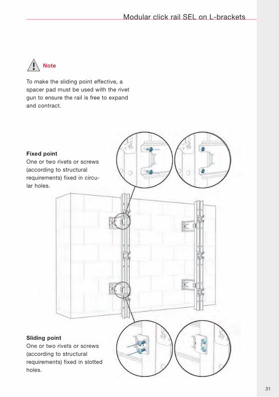
Fixed pointOne or two rivets or screws(according to structuralrequirements) fixed in circu-lar holes.
Sliding pointOne or two rivets or screws(according to structuralrequirements) fixed in slottedholes.
Note
To make the sliding point effective, aspacer pad must be used with the rivetgun to ensure the rail is free to expandand contract.
32
Modular click rail SE on U-brackets
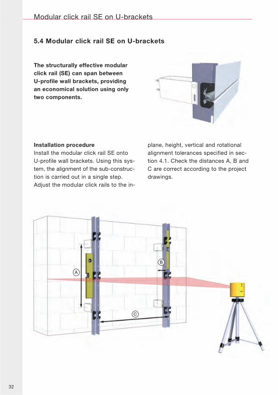
5.4 Modular click rail SE on U-brackets
The structurally effective modularclick rail (SE) can span betweenU-profile wall brackets, providingan economical solution using onlytwo components.
Installation procedureInstall the modular click rail SE ontoU-profile wall brackets. Using this sys-tem, the alignment of the sub-construc-tion is carried out in a single step.Adjust the modular click rails to the in-
plane, height, vertical and rotationalalignment tolerances specified in sec-tion 4.1. Check the distances A, B andC are correct according to the projectdrawings.
33
Modular click rail SE on U-brackets
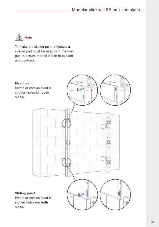
Note
To make the sliding point effective, aspacer pad must be used with the rivetgun to ensure the rail is free to expandand contract.
Fixed pointRivets or screws fixed incircular holes (on bothsides).
Sliding pointRivets or screws fixed inslotted holes (on bothsides).
34
Modular click rail SE on horizontal rails
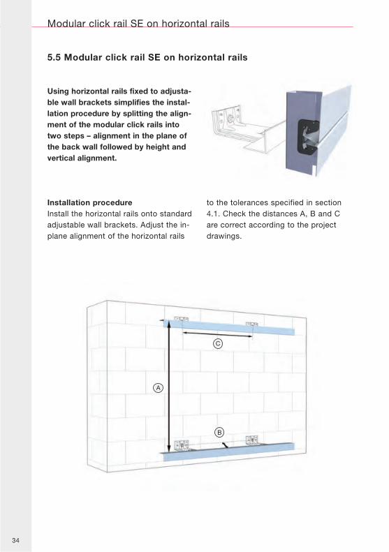
Using horizontal rails fixed to adjusta-ble wall brackets simplifies the instal-lation procedure by splitting the align-ment of the modular click rails intotwo steps – alignment in the plane ofthe back wall followed by height andvertical alignment.
Installation procedureInstall the horizontal rails onto standardadjustable wall brackets. Adjust the in-plane alignment of the horizontal rails
to the tolerances specified in section4.1. Check the distances A, B and Care correct according to the projectdrawings.
5.5 Modular click rail SE on horizontal rails
35
Modular click rail SE on horizontal rails
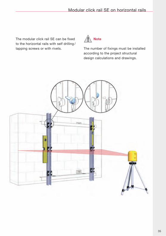
The modular click rail SE can be fixedto the horizontal rails with self drilling /tapping screws or with rivets.
Note
The number of fixings must be installedaccording to the project structuraldesign calculations and drawings.
36
Modular click rail SE on structural cassette
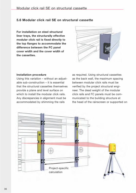
Project-specificcalculation
For installation on steel structuralliner trays, the structurally effectivemodular click rail is fixed directly tothe top flanges to accommodate thedifference between the FC panelcover width and the cover width ofthe cassettes.
5.6 Modular click rail SE on structural cassette
Installation procedureUsing this variation – without an adjust-able sub-construction – it is essentialthat the structural cassettes themselvesprovide a plane and level surface onwhich to install the modular click rails.Any discrepancies in alignment must beaccommodated by shimming the rails
as required. Using structural cassettesas the back wall, the maximum spacingbetween modular click rails must beverified by the project structural engi-neer. The dead weight of the modularclick rails and FC panels must be com-municated to the building structure atthe head of the rainscreen or supported on
37
Modular click rail SE on structural cassette
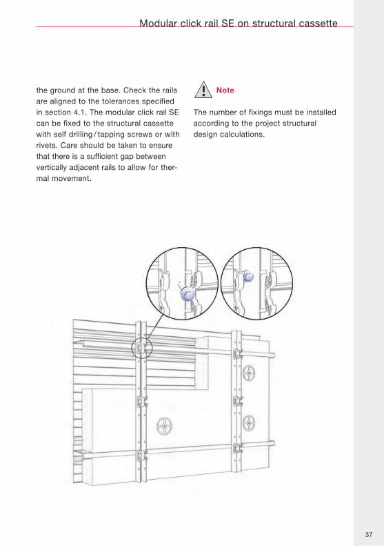
the ground at the base. Check the railsare aligned to the tolerances specifiedin section 4.1. The modular click rail SEcan be fixed to the structural cassettewith self drilling / tapping screws or withrivets. Care should be taken to ensurethat there is a sufficient gap betweenvertically adjacent rails to allow for ther-mal movement.
Note
The number of fixings must be installedaccording to the project structuraldesign calculations.
38
Modular click rail setting out tool
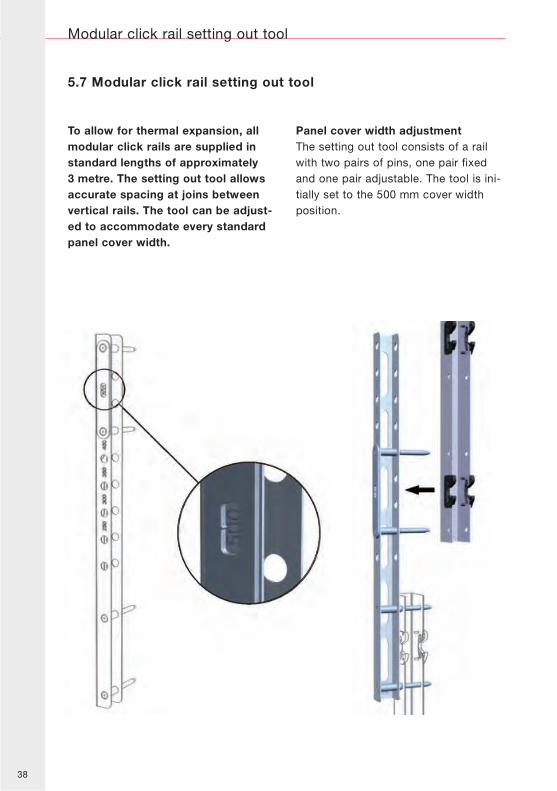
To allow for thermal expansion, allmodular click rails are supplied instandard lengths of approximately3 metre. The setting out tool allowsaccurate spacing at joins betweenvertical rails. The tool can be adjust-ed to accommodate every standardpanel cover width.
Panel cover width adjustmentThe setting out tool consists of a railwith two pairs of pins, one pair fixedand one pair adjustable. The tool is ini-tially set to the 500 mm cover widthposition.
5.7 Modular click rail setting out tool
39
Modular click rail setting out tool
1
4
2
5
3
6
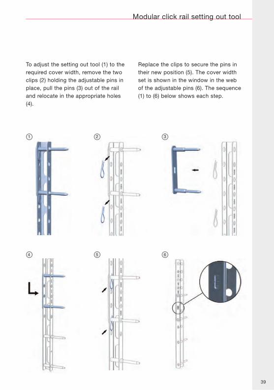
To adjust the setting out tool (1) to therequired cover width, remove the twoclips (2) holding the adjustable pins inplace, pull the pins (3) out of the railand relocate in the appropriate holes(4).
Replace the clips to secure the pins intheir new position (5). The cover widthset is shown in the window in the webof the adjustable pins (6). The sequence(1) to (6) below shows each step.
40
Modular click rail setting out tool
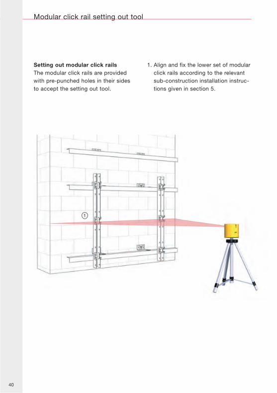
Setting out modular click railsThe modular click rails are providedwith pre-punched holes in their sidesto accept the setting out tool.
1. Align and fix the lower set of modularclick rails according to the relevantsub-construction installation instruc-tions given in section 5.
1
41
Modular click rail setting out tool
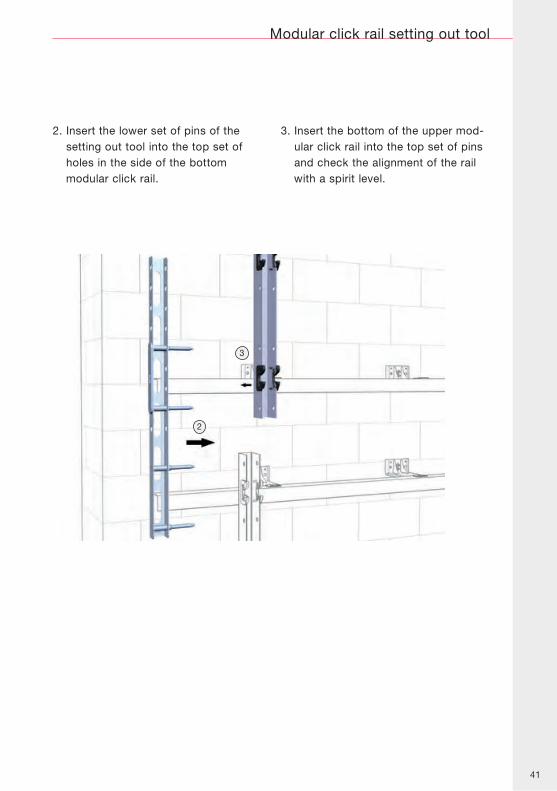
2. Insert the lower set of pins of thesetting out tool into the top set ofholes in the side of the bottommodular click rail.
3. Insert the bottom of the upper mod-ular click rail into the top set of pinsand check the alignment of the railwith a spirit level.
2
3
42
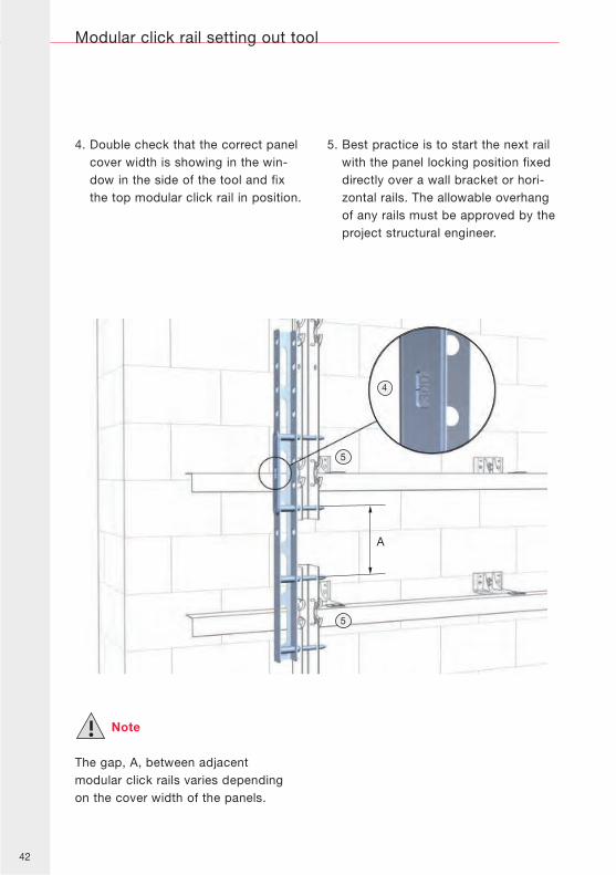
4. Double check that the correct panelcover width is showing in the win-dow in the side of the tool and fixthe top modular click rail in position.
5. Best practice is to start the next railwith the panel locking position fixeddirectly over a wall bracket or hori-zontal rails. The allowable overhangof any rails must be approved by theproject structural engineer.
Note
The gap, A, between adjacentmodular click rails varies dependingon the cover width of the panels.
Modular click rail setting out tool
A
4
5
5
43
Horizontal panel installation
6.0 Horizontal panel installation
Top panel edge
Bottom panel edge
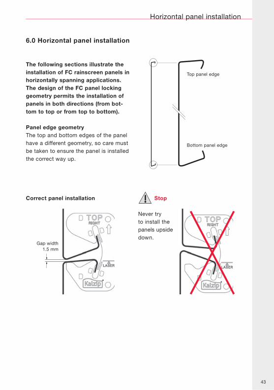
Gap width1.5 mm
Stop
Never tryto install thepanels upsidedown.
Correct panel installation
The following sections illustrate theinstallation of FC rainscreen panels inhorizontally spanning applications.The design of the FC panel lockinggeometry permits the installation ofpanels in both directions (from bot-tom to top or from top to bottom).
Panel edge geometryThe top and bottom edges of the panelhave a different geometry, so care mustbe taken to ensure the panel is installedthe correct way up.
44
6.1 Panel installation (bottom to top)
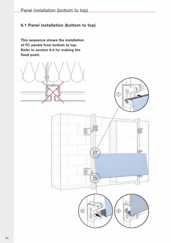
This sequence shows the installationof FC panels from bottom to top.Refer to section 6.4 for making thefixed point.
Panel installation (bottom to top)
1
2 3
45
Panel installation (bottom to top)
1. Hook the top edge of the first panelover both lower hooks of the mono-click bracket or modular click rail.Check that the panel can slide freelyleft to right.
2. Wearing gloves, use the palm ofthe hand to push the bottom edgeof panel into the upper part of thebracket.
3. The bottom edge of the panel shouldclick into place easily. Check againthat the whole panel can slide freelyleft to right.
Note
The panel overhang has been reducedin these drawings for clarity only. Referto the panel support requirements insection 4.2.
Stop
A single mono-click bracket or modularclick rail must never be used to supporttwo FC panels.
Caution
Always push the panel directly over thesupport bracket – not between the sup-ports.
Never force the panel into position –this will damage the edges and mayrequire panel replacement. If the paneldoes not click in easily, double-checkthe alignment of the sub-construction.
46
Panel installation (bottom to top)
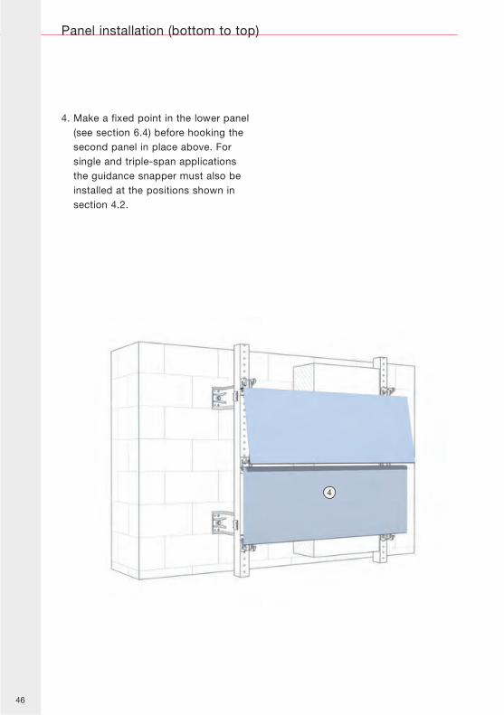
4. Make a fixed point in the lower panel(see section 6.4) before hooking thesecond panel in place above. Forsingle and triple-span applicationsthe guidance snapper must also beinstalled at the positions shown insection 4.2.
4
47
Panel installation (bottom to top)
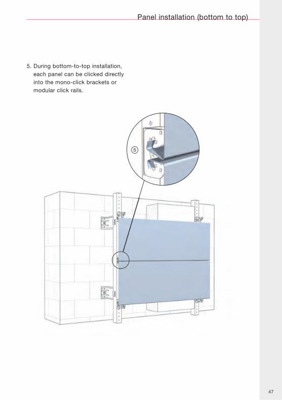
5. During bottom-to-top installation,each panel can be clicked directlyinto the mono-click brackets ormodular click rails.
5
48
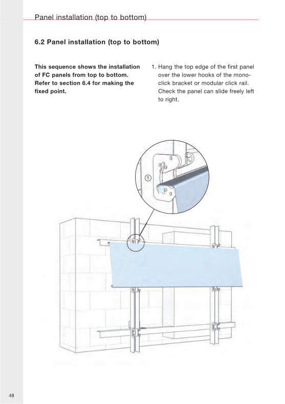
6.2 Panel installation (top to bottom)
This sequence shows the installationof FC panels from top to bottom.Refer to section 6.4 for making thefixed point.
1. Hang the top edge of the first panelover the lower hooks of the mono-click bracket or modular click rail.Check the panel can slide freely leftto right.
Panel installation (top to bottom)
1
49
Panel installation (top to bottom)
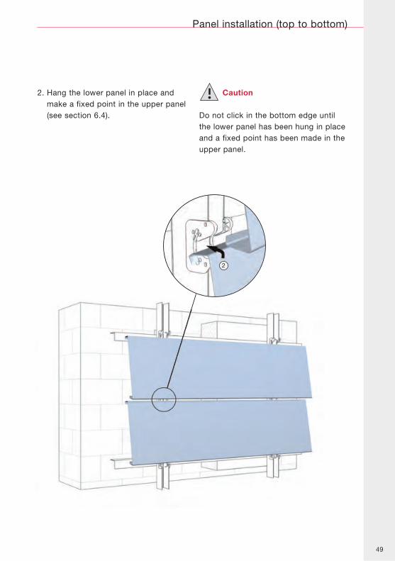
2. Hang the lower panel in place andmake a fixed point in the upper panel(see section 6.4).
Caution
Do not click in the bottom edge untilthe lower panel has been hung in placeand a fixed point has been made in theupper panel.
2
50
min. 10 mm
min. 80 mm
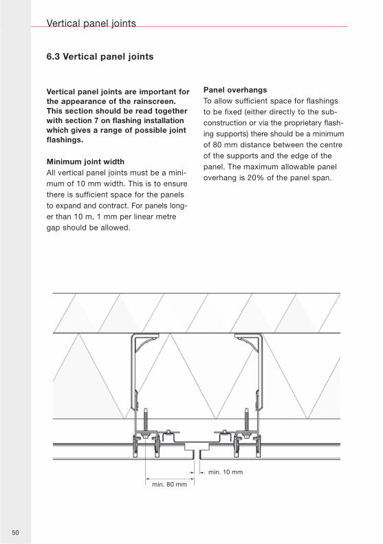
6.3 Vertical panel joints
Vertical panel joints are important forthe appearance of the rainscreen.This section should be read togetherwith section 7 on flashing installationwhich gives a range of possible jointflashings.
Minimum joint widthAll vertical panel joints must be a mini-mum of 10 mm width. This is to ensurethere is sufficient space for the panelsto expand and contract. For panels long-er than 10 m, 1 mm per linear metregap should be allowed.
Panel overhangsTo allow sufficient space for flashingsto be fixed (either directly to the sub-construction or via the proprietary flash-ing supports) there should be a minimumof 80 mm distance between the centreof the supports and the edge of thepanel. The maximum allowable paneloverhang is 20% of the panel span.
Vertical panel joints
51
min. 10 mmmin. 10 mm
min. 80 mm
Vertical panel joints
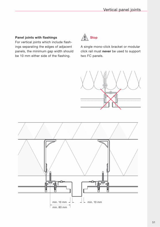
Panel joints with flashingsFor vertical joints which include flash-ings separating the edges of adjacentpanels, the minimum gap width shouldbe 10 mm either side of the flashing.
Stop
A single mono-click bracket or modularclick rail must never be used to supporttwo FC panels.
52
6.4 Fixed point
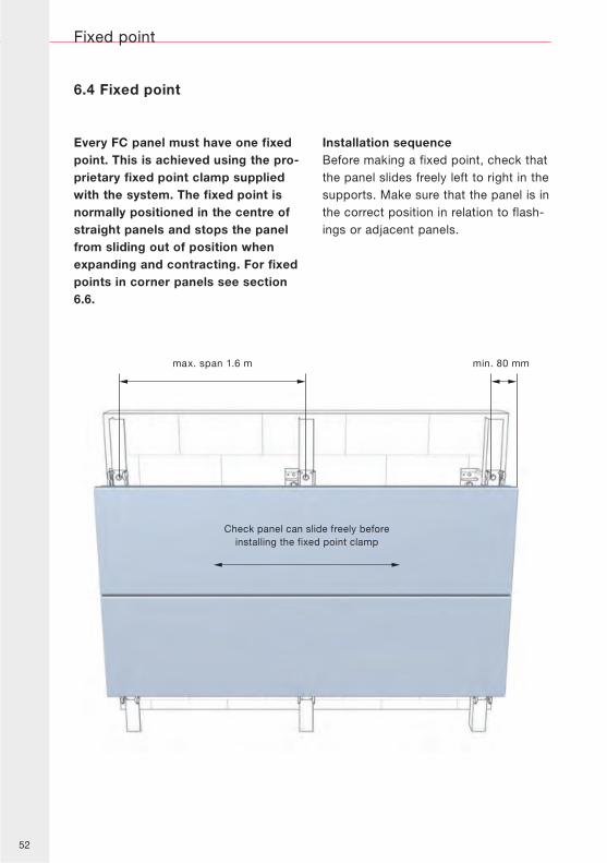
Every FC panel must have one fixedpoint. This is achieved using the pro-prietary fixed point clamp suppliedwith the system. The fixed point isnormally positioned in the centre ofstraight panels and stops the panelfrom sliding out of position whenexpanding and contracting. For fixedpoints in corner panels see section6.6.
Installation sequenceBefore making a fixed point, check thatthe panel slides freely left to right in thesupports. Make sure that the panel is inthe correct position in relation to flash-ings or adjacent panels.
Fixed point
max. span 1.6 m min. 80 mm
Check panel can slide freely beforeinstalling the fixed point clamp
53
1
3
2
4
Fixed point
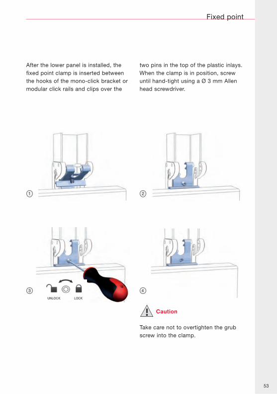
After the lower panel is installed, thefixed point clamp is inserted betweenthe hooks of the mono-click bracket ormodular click rails and clips over the
two pins in the top of the plastic inlays.When the clamp is in position, screwuntil hand-tight using a Ø 3 mm Allenhead screwdriver.
Caution
Take care not to overtighten the grubscrew into the clamp.
54
6.5 Adjustment of panel position
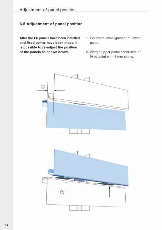
After the FC panels have been installedand fixed points have been made, itis possible to re-adjust the positionof the panels as shown below.
1. Horizontal misalignment of lowerpanel.
2. Wedge upper panel either side offixed point with 4 mm shims.
Adjustment of panel position
1
2
55
Adjustment of panel position
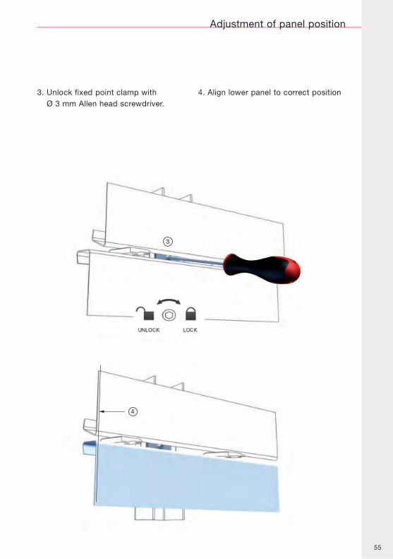
3. Unlock fixed point clamp withØ 3 mm Allen head screwdriver.
4. Align lower panel to correct position
3
4
56
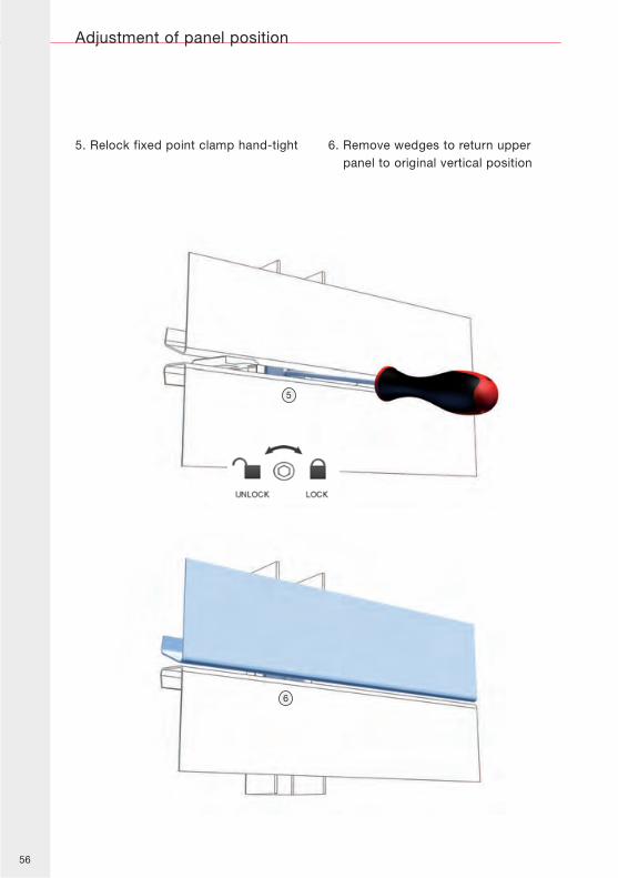
5. Relock fixed point clamp hand-tight 6. Remove wedges to return upperpanel to original vertical position
Adjustment of panel position
5
6
57
6.6 Corner panels
Corner panels
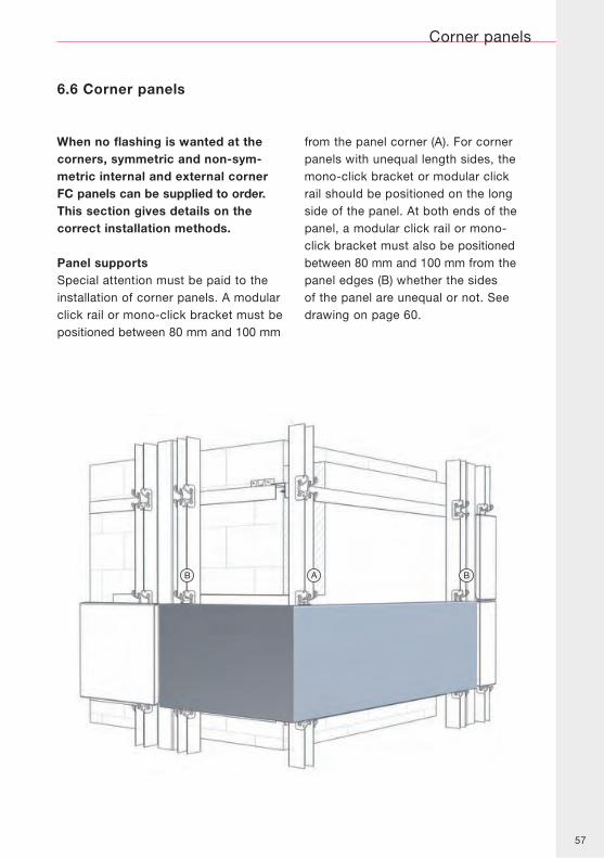
When no flashing is wanted at thecorners, symmetric and non-sym-metric internal and external cornerFC panels can be supplied to order.This section gives details on thecorrect installation methods.
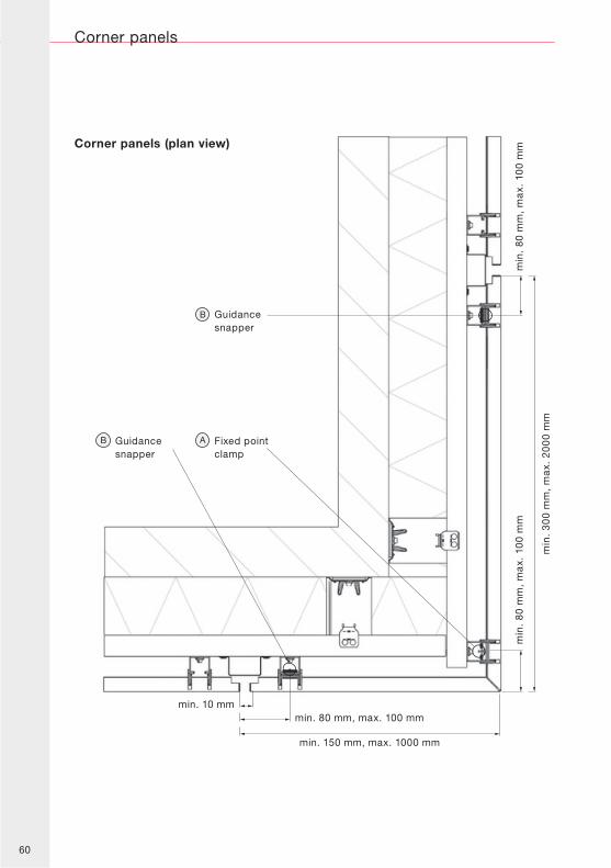
Panel supportsSpecial attention must be paid to theinstallation of corner panels. A modularclick rail or mono-click bracket must bepositioned between 80 mm and 100 mm
from the panel corner (A). For cornerpanels with unequal length sides, themono-click bracket or modular clickrail should be positioned on the longside of the panel. At both ends of thepanel, a modular click rail or mono-click bracket must also be positionedbetween 80 mm and 100 mm from thepanel edges (B) whether the sidesof the panel are unequal or not. Seedrawing on page 60.
58
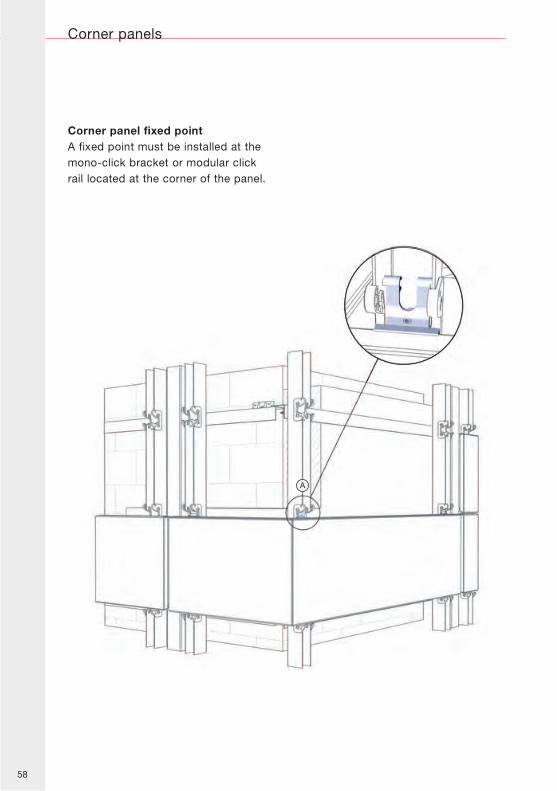
Corner panel fixed pointA fixed point must be installed at themono-click bracket or modular clickrail located at the corner of the panel.
Corner panels
59
Corner panels
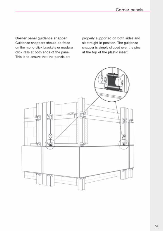
Corner panel guidance snapperGuidance snappers should be fittedon the mono-click brackets or modularclick rails at both ends of the panel.This is to ensure that the panels are
properly supported on both sides andsit straight in position. The guidancesnapper is simply clipped over the pinsat the top of the plastic insert.
60
Corner panels
Guidancesnapper
Fixed pointclamp
Guidancesnapper
min. 10 mm
min. 150 mm, max. 1000 mm
min. 80 mm, max. 100 mm
min
. 3
00
mm
, m
ax.
20
00
mm
min
. 80
mm
, m
ax.
10
0 m
m
min
. 80
mm
, m
ax.
10
0 m
mCorner panels (plan view)
61
1
2
Flashing installation
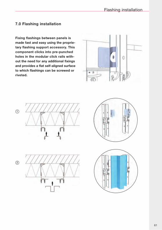
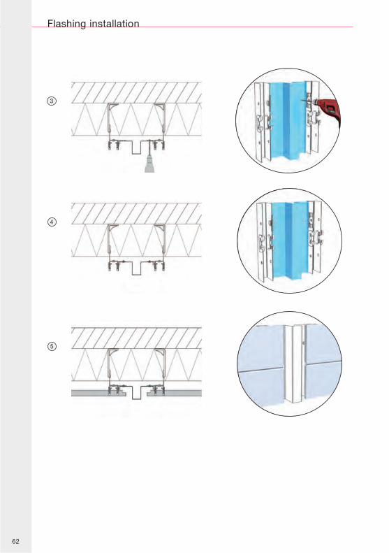
Fixing flashings between panels ismade fast and easy using the proprie-tary flashing support accessory. Thiscomponent clicks into pre-punchedholes in the modular click rails with-out the need for any additional fixingsand provides a flat self-aligned surfaceto which flashings can be screwed orriveted.
7.0 Flashing installation
62
4
5
3
Flashing installation
63
Individual panel replacement
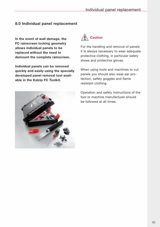
In the event of wall damage, theFC rainscreen locking geometryallows individual panels to bereplaced without the need todemount the complete rainscreen.
Individual panels can be removedquickly and easily using the speciallydeveloped panel removal tool avail-able in the Kalzip FC Toolkit.
Caution
For the handling and removal of panelsit is always necessary to wear adequateprotective clothing, in particular safetyshoes and protective gloves.
When using tools and machines to cutpanels you should also wear ear pro-tection, safety goggles and flameresistant clothing.
Operation and safety instructions of thetool or machine manufacturer shouldbe followed at all times.
8.0 Individual panel replacement
64
Individual panel replacement
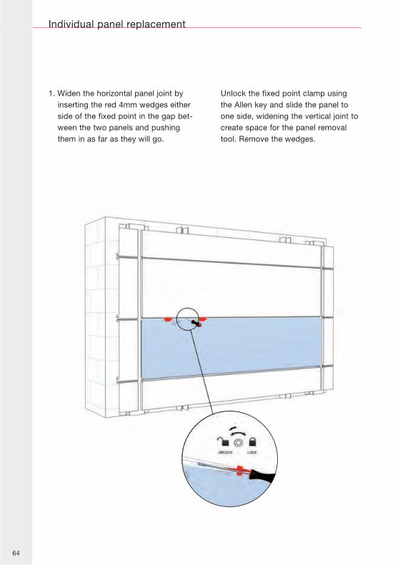
1. Widen the horizontal panel joint byinserting the red 4mm wedges eitherside of the fixed point in the gap bet-ween the two panels and pushingthem in as far as they will go.
Unlock the fixed point clamp usingthe Allen key and slide the panel toone side, widening the vertical joint tocreate space for the panel removaltool. Remove the wedges.
65
Individual panel replacement
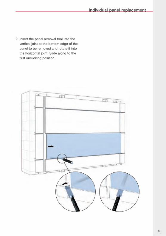
2. Insert the panel removal tool into thevertical joint at the bottom edge of thepanel to be removed and rotate it intothe horizontal joint. Slide along to thefirst unclicking position.
66
Individual panel replacement
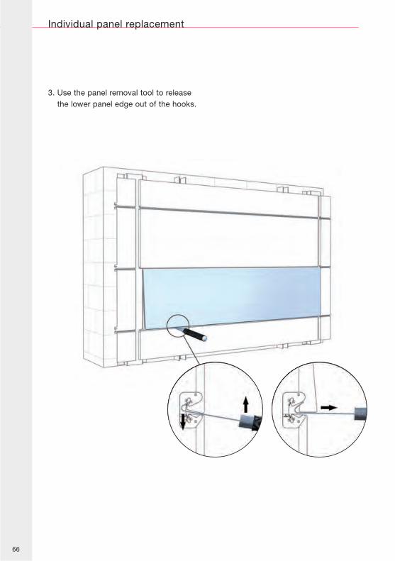
3. Use the panel removal tool to releasethe lower panel edge out of the hooks.
67
Individual panel replacement
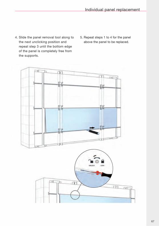
4. Slide the panel removal tool along tothe next unclicking position andrepeat step 3 until the bottom edgeof the panel is completely free fromthe supports.
5. Repeat steps 1 to 4 for the panelabove the panel to be replaced.
68
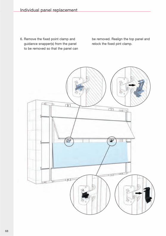
6. Remove the fixed point clamp andguidance snapper(s) from the panelto be removed so that the panel can
be removed. Realign the top panel andrelock the fixed pint clamp.
Individual panel replacement
69
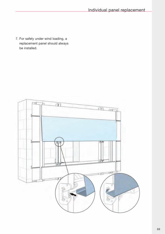
7. For safety under wind loading, areplacement panel should alwaysbe installed.
Individual panel replacement

70

71

72
While care has been taken to ensure that theinformation contained in this brochure is accurate,neither Tata Steel Europe Limited nor its subsidiariesaccept responsibility or liability for errors orinformation which is found to be misleading.
Copyright 2012
Kalzip Ltd
www.kalzip.com
Kalzip Ltd
Haydock Lane
Haydock
St Helens
Merseyside WA11 9TY
T: +44 (0) 1942 295500
F: +44 (0) 1942 295508
English
Kalzip Inc
4921C Ohio Street
Michgan City, IN 46360
USA
T: +1 219 879 2793
F: +1 219 879 2665
Kalzip FZE
PO Box 18294
Jebel Ali
Dubai
United Arab Emirates
T: +971 (0) 488 73 23 2
F: +971 (0) 488 73 97 7