Embed Size (px)
Citation preview

Moth
erbo
ard
K8V-VM Ultra
User Guide
ii
Copyright © 2006 ASUSTeK COMPUTER INC. All Rights Reserved.No part of this manual, including the products and software described in it, may be reproduced, transmitted, transcribed, stored in a retrieval system, or translated into any language in any form or by any means, except documentation kept by the purchaser for backup purposes, without the express written permission of ASUSTeK COMPUTER INC. (“ASUS”).Product warranty or service will not be extended if: (1) the product is repaired, modified or altered, unless such repair, modification of alteration is authorized in writing by ASUS; or (2) the serial number of the product is defaced or missing.ASUS PROVIDES THIS MANUAL “AS IS” WITHOUT WARRANTY OF ANY KIND, EITHER EXPRESS OR IMPLIED, INCLUDING BUT NOT LIMITED TO THE IMPLIED WARRANTIES OR CONDITIONS OF MERCHANTABILITY OR FITNESS FOR A PARTICULAR PURPOSE. IN NO EVENT SHALL ASUS, ITS DIRECTORS, OFFICERS, EMPLOYEES OR AGENTS BE LIABLE FOR ANY INDIRECT, SPECIAL, INCIDENTAL, OR CONSEQUENTIAL DAMAGES (INCLUDING DAMAGES FOR LOSS OF PROFITS, LOSS OF BUSINESS, LOSS OF USE OR DATA, INTERRUPTION OF BUSINESS AND THE LIKE), EVEN IF ASUS HAS BEEN ADVISED OF THE POSSIBILITY OF SUCH DAMAGES ARISING FROM ANY DEFECT OR ERROR IN THIS MANUAL OR PRODUCT.SPECIFICATIONS AND INFORMATION CONTAINED IN THIS MANUAL ARE FURNISHED FOR INFORMATIONAL USE ONLY, AND ARE SUBJECT TO CHANGE AT ANY TIME WITHOUT NOTICE, AND SHOULD NOT BE CONSTRUED AS A COMMITMENT BY ASUS. ASUS ASSUMES NO RESPONSIBILITY OR LIABILITY FOR ANY ERRORS OR INACCURACIES THAT MAY APPEAR IN THIS MANUAL, INCLUDING THE PRODUCTS AND SOFTWARE DESCRIBED IN IT.Products and corporate names appearing in this manual may or may not be registered trademarks or copyrights of their respective companies, and are used only for identification or explanation and to the owners’ benefit, without intent to infringe.
E2467
First Edition April 2006
iii
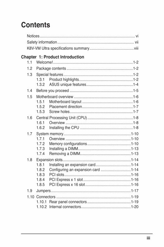
ContentsNotices ............................................................................................ viSafety information .......................................................................... viiK8V-VM Ultra specifications summary ...........................................viii
Chapter 1: Product Introduction1.1 Welcome! .............................................................................1-21.2 Package contents ................................................................1-21.3 Special features ...................................................................1-2
1.3.1 Product highlights ....................................................1-21.3.2 ASUS unique features .............................................1-4
1.4 Before you proceed .............................................................1-51.5 Motherboard overview .........................................................1-6
1.5.1 Motherboard layout .................................................1-61.5.2 Placement direction .................................................1-71.5.3 Screw holes .............................................................1-7
1.6 Central Processing Unit (CPU) ............................................1-81.6.1 Overview .................................................................1-81.6.2 Installing the CPU ...................................................1-8
1.7 System memory .................................................................1-101.7.1 Overview ...............................................................1-101.7.2 Memory configurations ..........................................1-101.7.3 Installing a DIMM ...................................................1-131.7.4 Removing a DIMM .................................................1-13
1.8 Expansion slots ..................................................................1-141.8.1 Installing an expansion card ..................................1-141.8.2 Configuring an expansion card .............................1-141.8.3 PCI slots ................................................................1-161.8.4 PCI Express x 1 slot ..............................................1-161.8.5 PCI Express x 16 slot ............................................1-16
1.9 Jumpers .............................................................................1-171.10 Connectors ........................................................................1-19
1.10.1 Rear panel connectors ..........................................1-191.10.2 Internal connectors ................................................1-20
iv
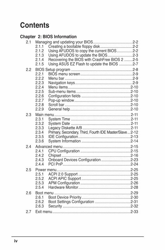
ContentsChapter 2: BIOS Information
2.1 Managing and updating your BIOS ......................................2-22.1.1 Creating a bootable floppy disk ...............................2-22.1.2 Using AFUDOS to copy the current BIOS ...............2-22.1.3 Using AFUDOS to update the BIOS ........................2-32.1.4 Recovering the BIOS with CrashFree BIOS 2 ........2-52.1.5 Using ASUS EZ Flash to update the BIOS .............2-7
2.2 BIOS Setup program ...........................................................2-82.2.1 BIOS menu screen ..................................................2-92.2.2 Menu bar .................................................................2-92.2.3 Navigation keys .......................................................2-92.2.4 Menu items ............................................................2-102.2.5 Sub-menu items ....................................................2-102.2.6 Configuration fields ...............................................2-102.2.7 Pop-up window ......................................................2-102.2.8 Scroll bar ...............................................................2-102.2.9 General help ..........................................................2-10
2.3 Main menu .........................................................................2-112.3.1 System Time .........................................................2-112.3.2 System Date .........................................................2-112.3.3 Legacy Diskette A/B ..............................................2-112.3.4 Primary, Secondary, Third, Fourth IDE Master/Slave ...2-122.3.5 IDE Configuration ..................................................2-132.3.6 System Information ...............................................2-14
2.4 Advanced menu .................................................................2-152.4.1 CPU Configuration ................................................2-152.4.2 Chipset ..................................................................2-162.4.3 Onboard Devices Configuration ............................2-232.4.4 PCI PnP .................................................................2-24
2.5 Power menu .......................................................................2-252.5.1 ACPI 2.0 Support ..................................................2-252.5.2 ACPI APIC Support ...............................................2-252.5.3 APM Configuration ................................................2-262.5.4 Hardware Monitor ..................................................2-28
2.6 Boot menu .........................................................................2-292.6.1 Boot Device Priority ...............................................2-302.6.2 Boot Settings Configuration ..................................2-312.6.3 Security .................................................................2-32
2.7 Exit menu ...........................................................................2-33
v
ContentsChapter 3: Software Support
3.1 Installing an operating system .............................................3-23.2 Support CD information .......................................................3-2
3.2.1 Running the support CD ..........................................3-23.2.2 Drivers menu ...........................................................3-33.2.3 Utilities menu ...........................................................3-33.2.4 Make disk menu ......................................................3-53.2.5 Manuals menu .........................................................3-53.2.6 ASUS contact information .......................................3-6

vi
NoticesFederal Communications Commission StatementThis device complies with Part 15 of the FCC Rules. Operation is subject to the following two conditions:• This device may not cause harmful interference, and• This device must accept any interference received including
interference that may cause undesired operation.This equipment has been tested and found to comply with the limits for a Class B digital device, pursuant to Part 15 of the FCC Rules. These limits are designed to provide reasonable protection against harmful interference in a residential installation. This equipment generates, uses and can radiate radio frequency energy and, if not installed and used in accordance with manufacturer’s instructions, may cause harmful interference to radio communications. However, there is no guarantee that interference will not occur in a particular installation. If this equipment does cause harmful interference to radio or television reception, which can be determined by turning the equipment off and on, the user is encouraged to try to correct the interference by one or more of the following measures:• Reorient or relocate the receiving antenna.• Increase the separation between the equipment and receiver.• Connect the equipment to an outlet on a circuit different from that to
which the receiver is connected.• Consult the dealer or an experienced radio/TV technician for help.
Canadian Department of Communications StatementThis digital apparatus does not exceed the Class B limits for radio noise emissions from digital apparatus set out in the Radio Interference Regulations of the Canadian Department of Communications.This class B digital apparatus complies with Canadian ICES-003.
To assure compliance with FCC regulations, use shielded cables to connect the monitor to the graphics card. Changes to this unit not expressly approved by the party responsible for compliance can void the user’s authority to operate this equipment.
vii
Safety InformationElectrical safety• To prevent electrical shock hazard, disconnect the power cable from
the electrical outlet before relocating the system.• When adding or removing devices to or from the system, ensure that
the power cables for the devices are unplugged before the signal cables are connected. If possible, disconnect all power cables from the existing system before you add a device.
• Before connecting or removing signal cables from the motherboard, ensure that all power cables are unplugged.
• Seek professional assistance before using an adapter or extension cord. These devices can interrupt the grounding circuit.
• Set your power supply to the correct voltage in your area. If you are not sure about the voltage of the electrical outlet you are using, contact your local power company.
• If the power supply is broken, do not try to fix it by yourself. Contact a qualified service technician or your retailer.
Operational safety• Before installing the motherboard and adding devices on it, carefully
read all the manuals that came with the package.• Before using the product, make sure all cables are correctly connected
and the power cables are not damaged. If you detect any damage, contact your dealer immediately.
• To avoid short circuits, keep paper clips, screws, and staples away from connectors, slots, sockets, and circuitry.
• Avoid dust, humidity, and temperature extremes. Do not place the product in any area where it can get wet.
• Place the product on a stable surface.• If you encounter technical problems with the product, contact a
qualified service technician or your retailer.
The symbol of the crossed out wheeled bin indicates that the product (electrical and electronic equipment) should not be placed in municipal waste. Check local regulations for disposal of electronic products.
viii
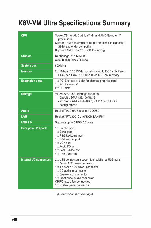
Socket 754 for AMD Athlon™ 64 and AMD Sempron™ processors Supports AMD 64 architecture that enables simultaneous 32-bit and 64-bit computing Supports AMD Cool ‘n’ Quiet! Technology
Northbridge: VIA K8M890 Southbridge: VIA VT8237A
800 MHz
2 x 184-pin DDR DIMM sockets for up to 2 GB unbuffered ECC, non-ECC DDR 400/333/266 DRAM memory
1 x PCI Express x16 slot for discrete graphics card 1 x PCI Express x1 2 x PCI slots
VIA VT8237A SouthBridge supports: - 2 x Ultra DMA 133/100/66/33 - 2 x Serial ATA with RAID 0, RAID 1, and JBOD configurations
Realtek® ALC660 6-channel CODEC
Realtek® RTL8201CL 10/100M LAN PHY
Supports up to 8 USB 2.0 ports
1 x Parallel port 1 x Serial port 1 x PS/2 keyboard port 1 x PS/2 mouse port 1 x VGA port 1 x Audio I/O port 1 x LAN (RJ-45) port 4 x USB 2.0 ports
2 x USB connectors support four additional USB ports 1 x 24-pin ATX power connector 1 x 4-pin ATX 12V power connector 1 x CD audio in connector 1 x Speaker out connector 1 x Front panel audio connector CPU/Chassis fan connectors 1 x System panel connector
K8V-VM Ultra Specifications SummaryCPU
Chipset
System bus
Memory
Expansion slots
Storage
Audio
LAN
USB 2.0
Rear panel I/O ports
Internal I/O connectors
(Continued on the next page)
ix
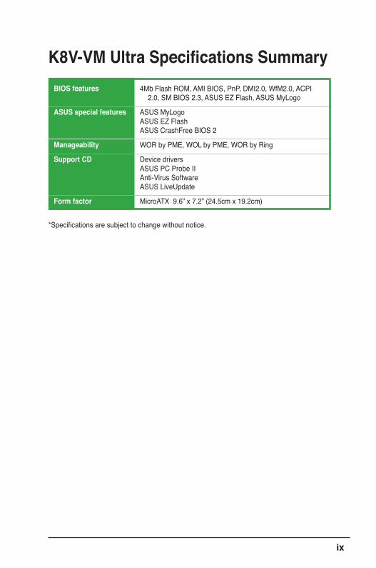
K8V-VM Ultra Specifications Summary
*Specifications are subject to change without notice.
BIOS features
ASUS special features
Manageability
Support CD
Form factor
4Mb Flash ROM, AMI BIOS, PnP, DMI2.0, WfM2.0, ACPI 2.0, SM BIOS 2.3, ASUS EZ Flash, ASUS MyLogo
ASUS MyLogo ASUS EZ Flash ASUS CrashFree BIOS 2
WOR by PME, WOL by PME, WOR by Ring
Device drivers ASUS PC Probe II Anti-Virus Software ASUS LiveUpdate
MicroATX 9.6” x 7.2” (24.5cm x 19.2cm)

x
Chapter 1
This chapter describes the features of this motherboard. It includes brief explanations of the special attributes of the motherboard and the new technology it supports.
Product Introduction
1-2 Chapter 1: Product Introduction
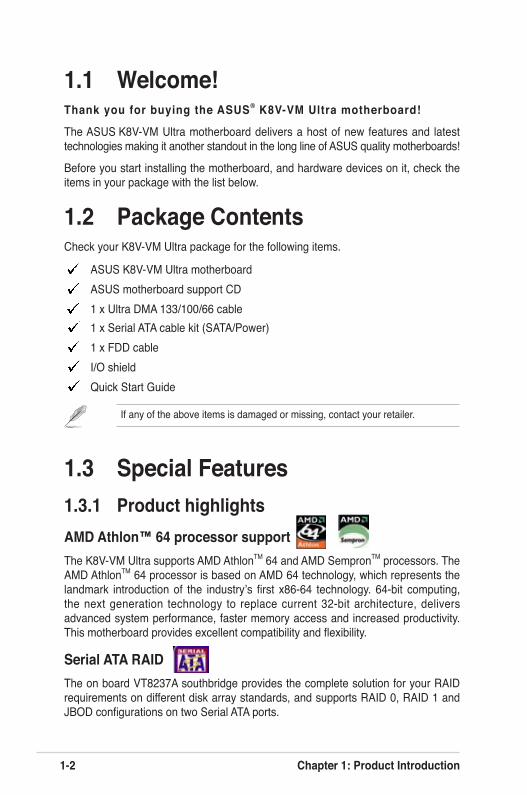
1.3 Special Features1.3.1 Product highlightsAMD Athlon™ 64 processor supportThe K8V-VM Ultra supports AMD AthlonTM 64 and AMD SempronTM processors. The AMD AthlonTM 64 processor is based on AMD 64 technology, which represents the landmark introduction of the industry’s first x86-64 technology. 64-bit computing, the next generation technology to replace current 32-bit architecture, delivers advanced system performance, faster memory access and increased productivity. This motherboard provides excellent compatibility and flexibility.
Serial ATA RAID The on board VT8237A southbridge provides the complete solution for your RAID requirements on different disk array standards, and supports RAID 0, RAID 1 and JBOD configurations on two Serial ATA ports.
1.1 Welcome!Thank you for buying the ASUS® K8V-VM Ultra motherboard!
The ASUS K8V-VM Ultra motherboard delivers a host of new features and latest technologies making it another standout in the long line of ASUS quality motherboards!
Before you start installing the motherboard, and hardware devices on it, check the items in your package with the list below.
1.2 Package ContentsCheck your K8V-VM Ultra package for the following items.
ASUS K8V-VM Ultra motherboard ASUS motherboard support CD 1 x Ultra DMA 133/100/66 cable
1 x Serial ATA cable kit (SATA/Power) 1 x FDD cable I/O shield Quick Start Guide
If any of the above items is damaged or missing, contact your retailer.
ASUS K8V-VM Ultra Motherboard 1-3
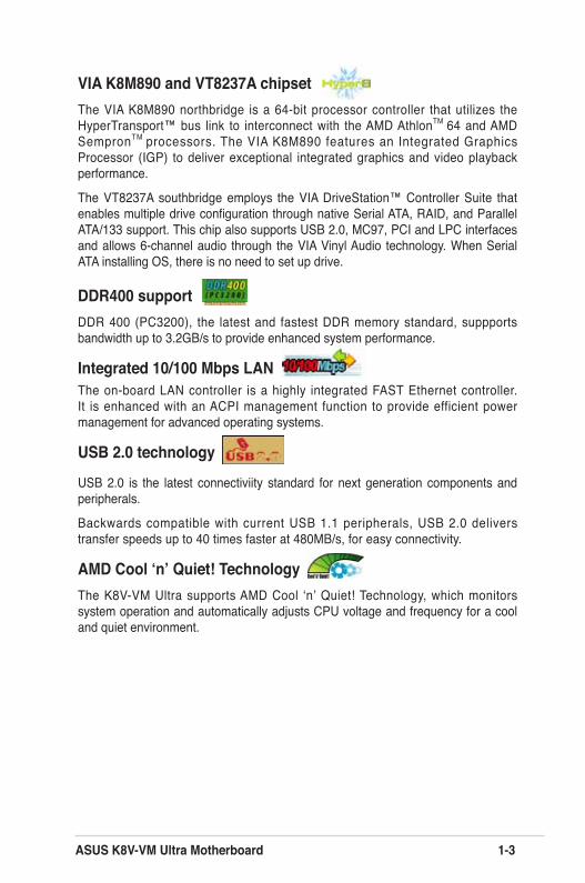
VIA K8M890 and VT8237A chipsetThe VIA K8M890 northbridge is a 64-bit processor controller that utilizes the HyperTransport™ bus link to interconnect with the AMD AthlonTM 64 and AMD SempronTM processors. The VIA K8M890 features an Integrated Graphics Processor (IGP) to deliver exceptional integrated graphics and video playback performance.
The VT8237A southbridge employs the VIA DriveStation™ Controller Suite that enables multiple drive configuration through native Serial ATA, RAID, and Parallel ATA/133 support. This chip also supports USB 2.0, MC97, PCI and LPC interfaces and allows 6-channel audio through the VIA Vinyl Audio technology. When Serial ATA installing OS, there is no need to set up drive.
DDR400 supportDDR 400 (PC3200), the latest and fastest DDR memory standard, suppports bandwidth up to 3.2GB/s to provide enhanced system performance.
Integrated 10/100 Mbps LANThe on-board LAN controller is a highly integrated FAST Ethernet controller. It is enhanced with an ACPI management function to provide efficient power management for advanced operating systems.
USB 2.0 technology
USB 2.0 is the latest connectiviity standard for next generation components and peripherals.
Backwards compatible with current USB 1.1 peripherals, USB 2.0 delivers transfer speeds up to 40 times faster at 480MB/s, for easy connectivity.
AMD Cool ‘n’ Quiet! Technology The K8V-VM Ultra supports AMD Cool ‘n’ Quiet! Technology, which monitors system operation and automatically adjusts CPU voltage and frequency for a cool and quiet environment.

1-4 Chapter 1: Product Introduction
1.3.2 ASUS unique featuresEZ Flash BIOS With the ASUS EZ Flash, you can easily update the system BIOS even before loading the operating system. No need to use a DOS-based utility or boot from a floppy disk. See page 2-7.
CrashFree BIOS 2 Whenever BIOS gets corrupted, ASUS CrashFree BIOS2 allows users to reboot the computer and perform an smart auto-recovery procedure through the motherboard support CD. See page 2-5.
ASUS MyLogo™ This feature allows you to personalize and add style to your system with customizable boot logos. See pages 2-31.
ASUS K8V-VM Ultra Motherboard 1-5
1.4 Before You ProceedTake note of the following precautions before you install motherboard components or change any motherboard settings.
• Unplug the power cord from the wall socket before touching any component.
• Use a grounded wrist strap or touch a safely grounded object or a metal object, such as the power supply case, before handling components to avoid damaging them due to static electricity.
• Hold components by the edges to avoid touching the ICs on them.
• Whenever you uninstall any component, place it on a grounded antistatic pad or in the bag that came with the component.
• Before you install or remove any component, ensure that the ATX power supply is switched off or the power cord is detached from the power supply. Failure to do so may cause severe damage to the motherboard, peripherals, and/or components.
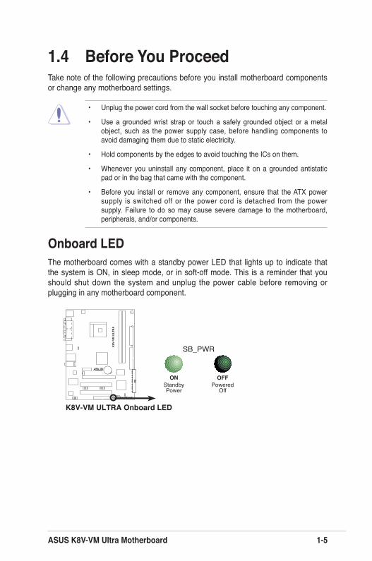
Onboard LEDThe motherboard comes with a standby power LED that lights up to indicate that the system is ON, in sleep mode, or in soft-off mode. This is a reminder that you should shut down the system and unplug the power cable before removing or plugging in any motherboard component.
K8V-VM ULTRA Onboard LED
SB_PWR
ONStandbyPower
OFFPowered
Off
r
R
K8V
-VM
ULT
RA
1-6 Chapter 1: Product Introduction
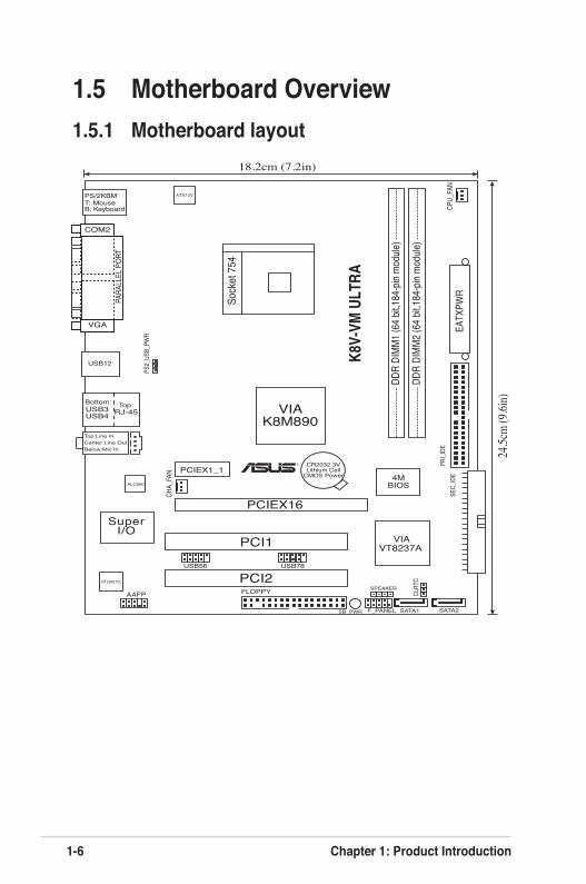
1.5 Motherboard Overview1.5.1 Motherboard layout
Sock
et 7
54
FLOPPY
VIAK8M890
Below:Mic InCenter:Line OutTop:Line In
RJ-45Top:USB3
USB4
Bottom:
VIAVT8237A
AAFP
SB_PWR
DDR
DIMM
1 (64
bit,1
84-p
in mo
dule)
DDR
DIMM
2 (64
bit,1
84-p
in mo
dule)
EATX
PWR
USB12
PS/2KBMT: MouseB: Keyboard
ATX12V
CR2032 3VLithium Cell
CMOS Power
PCIEX16
PCI1
PCI2
4MBIOSALC660
RTL8201CL
SATA1F_PANEL SATA2
CHA_
FAN
SuperI/O
PRI_I
DECP
U_FA
N
PS2_
USB_
PWR
COM2
PARA
LLEL
POR
T
VGA
USB56 USB78
PCIEX1_1
CLRT
C
18.2cm (7.2in)
24.5c
m (9
.6in)
R
K8V-
VM U
LTRA
SPEAKER
SEC_
IDE
ASUS K8V-VM Ultra Motherboard 1-7
:
r
R
K8V
-VM
ULT
RA
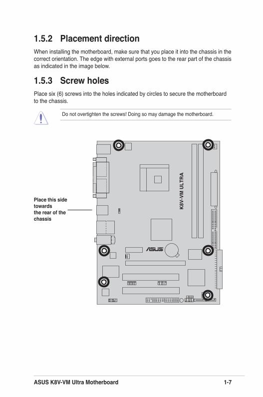
Do not overtighten the screws! Doing so may damage the motherboard.
1.5.2 Placement directionWhen installing the motherboard, make sure that you place it into the chassis in the correct orientation. The edge with external ports goes to the rear part of the chassis as indicated in the image below.
1.5.3 Screw holesPlace six (6) screws into the holes indicated by circles to secure the motherboard to the chassis.
Place this side towards the rear of the chassis
1-8 Chapter 1: Product Introduction
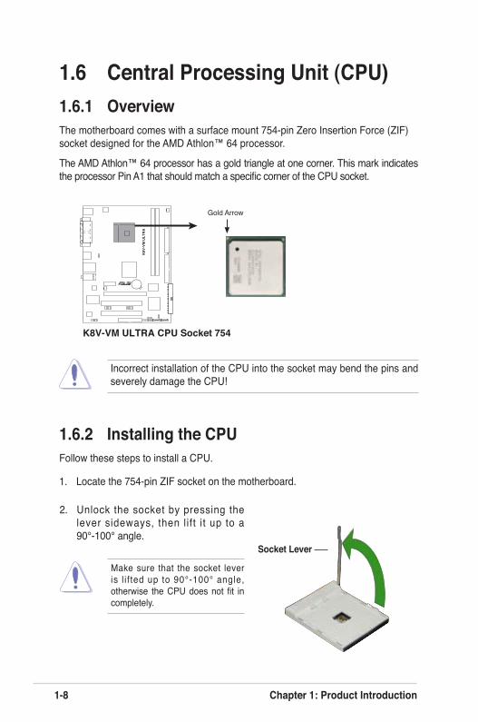
K8V-VM ULTRA CPU Socket 754
Gold Arrow
r
R
K8V
-VM
ULT
RA
2. Unlock the socket by pressing the lever sideways, then lift it up to a 90°-100° angle.
Socket Lever
Make sure that the socket lever is l i f ted up to 90°-100° angle, otherwise the CPU does not fit in completely.
1.6.2 Installing the CPUFollow these steps to install a CPU.
1. Locate the 754-pin ZIF socket on the motherboard.
1.6 Central Processing Unit (CPU)1.6.1 OverviewThe motherboard comes with a surface mount 754-pin Zero Insertion Force (ZIF) socket designed for the AMD Athlon™ 64 processor.
The AMD Athlon™ 64 processor has a gold triangle at one corner. This mark indicates the processor Pin A1 that should match a specific corner of the CPU socket.
Incorrect installation of the CPU into the socket may bend the pins and severely damage the CPU!
ASUS K8V-VM Ultra Motherboard 1-9
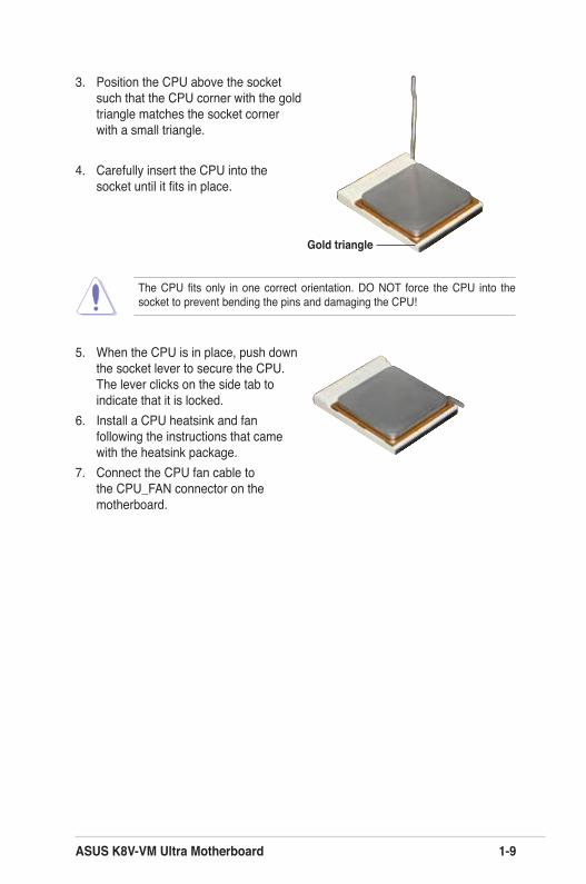
3. Position the CPU above the socket such that the CPU corner with the gold triangle matches the socket corner with a small triangle.
4. Carefully insert the CPU into the socket until it fits in place.
5. When the CPU is in place, push down the socket lever to secure the CPU. The lever clicks on the side tab to indicate that it is locked.
6. Install a CPU heatsink and fan following the instructions that came with the heatsink package.
7. Connect the CPU fan cable to the CPU_FAN connector on the motherboard.
The CPU fits only in one correct orientation. DO NOT force the CPU into the socket to prevent bending the pins and damaging the CPU!
Gold triangle
1-10 Chapter 1: Product Introduction
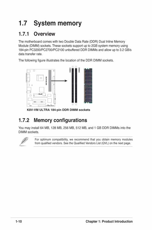
1.7 System memory1.7.1 OverviewThe motherboard comes with two Double Data Rate (DDR) Dual Inline Memory Module (DIMM) sockets. These sockets support up to 2GB system memory using 184-pin PC3200/PC2700/PC2100 unbuffered DDR DIMMs and allow up to 3.2 GB/s data transfer rate.
The following figure illustrates the location of the DDR DIMM sockets.
1.7.2 Memory configurationsYou may install 64 MB, 128 MB, 256 MB, 512 MB, and 1 GB DDR DIMMs into the DIMM sockets.
For optimum compatibility, we recommend that you obtain memory modules from qualified vendors. See the Qualified Vendors List (QVL) on the next page.
K8V
-VM
ULT
RA
K8V-VM ULTRA 184-pin DDR DIMM sockets
DIM
M1
DIM
M2
r
R
K8V
-VM
ULT
RA
ASUS K8V-VM Ultra Motherboard 1-11
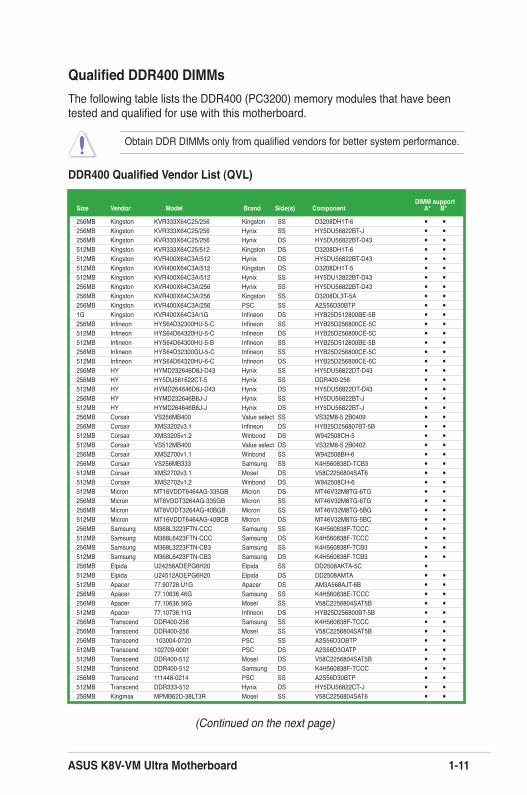
Qualified DDR400 DIMMsThe following table lists the DDR400 (PC3200) memory modules that have been tested and qualified for use with this motherboard.
Obtain DDR DIMMs only from qualified vendors for better system performance.
DDR400 Qualified Vendor List (QVL)
(Continued on the next page)
DIMM supportSize Vendor Model Brand Side(s) Component A* B*
256MB Kingston KVR333X64C25/256 Kingston SS D3208DH1T-6 • •256MB Kingston KVR333X64C25/256 Hynix SS HY5DU56822BT-J • •256MB Kingston KVR333X64C25/256 Hynix DS HY5DU56822BT-D43 • •512MB Kingston KVR333X64C25/512 Kingston DS D3208DH1T-6 • •512MB Kingston KVR400X64C3A/512 Hynix DS HY5DU56822BT-D43 • •512MB Kingston KVR400X64C3A/512 Kingston DS D3208DH1T-5 • •512MB Kingston KVR400X64C3A/512 Hynix SS HY5DU12822BT-D43 • •256MB Kingston KVR400X64C3A/256 Hynix SS HY5DU56822BT-D43 • •256MB Kingston KVR400X64C3A/256 Kingston SS D3208DL3T-5A • •256MB Kingston KVR400X64C3A/256 PSC SS A2S56D30BTP • •1G Kingston KVR400X64C3A/1G Infineon DS HYB25D512800BE-5B • •256MB Infineon HYS64D32300HU-5-C Infineon SS HYB25D256800CE-5C • •512MB Infineon HYS64D64320HU-5-C Infineon DS HYB25D256800CE-5C • •512MB Infineon HYS64D64300HU-5-B Infineon SS HYB25D512800BE-5B • •256MB Infineon HYS64D32300GU-5-C Infineon SS HYB25D256800CE-5C • •512MB Infineon HYS64D64320HU-6-C Infineon DS HYB25D256800CE-6C • •256MB HY HYMD232646D8J-D43 Hynix SS HY5DU56822DT-D43 • •256MB HY HY5DU561622CT-5 Hynix SS DDR400-256 • •512MB HY HYMD264646D8J-D43 Hynix DS HY5DU56822DT-D43 • •256MB HY HYMD232646B8J-J Hynix SS HY5DU56822BT-J • •512MB HY HYMD264646B8J-J Hynix DS HY5DU56822BT-J • •256MB Corsair VS256MB400 Value select SS VS32M8-5 2B0409 • •256MB Corsair XMS3202v3.1 Infineon DS HYB25D256807BT-5B • •512MB Corsair XMS3205v1.2 Winbond DS W942508CH-5 • •512MB Corsair VS512MB400 Value select DS VS32M8-5 2B0402 • •256MB Corsair XMS2700v1.1 Winbond SS W942508BH-6 • •256MB Corsair VS256MB333 Samsung SS K4H560838D-TCB3 • •512MB Corsair XMS2702v3.1 Mosel DS V58C2256804SAT6 • •512MB Corsair XMS2702v1.2 Winbond DS W942508CH-6 • •512MB Micron MT16VDDT6464AG-335GB Micron DS MT46V32M8TG-6TG • •256MB Micron MT8VDDT3264AG-335GB Micron SS MT46V32M8TG-6TG • •256MB Micron MT8VDDT3264AG-40BGB Micron SS MT46V32M8TG-5BG • •512MB Micron MT16VDDT6464AG-40BCB Micron DS MT46V32M8TG-5BC • •256MB Samsung M368L3223FTN-CCC Samsung SS K4H560838F-TCCC • •512MB Samsung M368L6423FTN-CCC Samsung DS K4H560838F-TCCC • •256MB Samsung M368L3223FTN-CB3 Samsung SS K4H560838F-TCB3 • •512MB Samsung M368L6423FTN-CB3 Samsung DS K4H560838F-TCB3 • •256MB Elpida U24256ADEPG6H20 Elpida SS DD2508AKTA-5C • 512MB Elpida U24512ADEPG6H20 Elpida DS DD2508AMTA • •512MB Apacer 77.90728.U1G Apacer DS AM3A568AJT-6B • •256MB Apacer 77.10636.46G Samsung SS K4H560838E-TCCC • •256MB Apacer 77.10636.56G Mosel SS V58C2256804SAT5B • •512MB Apacer 77.10736.11G Infineon DS HYB25D256800BT-5B • •256MB Transcend DDR400-256 Samsung SS K4H560838F-TCCC • •256MB Transcend DDR400-256 Mosel SS V58C2256804SAT5B • •256MB Transcend 103004-0720 PSC SS A2S56D3OBTP • •512MB Transcend 102709-0001 PSC DS A2S56D3OATP • •512MB Transcend DDR400-512 Mosel DS V58C2256804SAT5B • •512MB Transcend DDR400-512 Samsung DS K4H560838F-TCCC • •256MB Transcend 111448-0214 PSC SS A2S56D30BTP • •512MB Transcend DDR333-512 Hynix DS HY5DU56822CT-J • •256MB Kingmax MPMB62D-38LT3R Mosel SS V58C2256804SAT6 • •
1-12 Chapter 1: Product Introduction
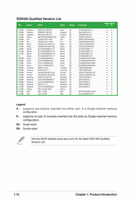
Legend:A - supports one module inserted into either slot, in a Single-channel memory
configuration.B - supports on pair of modules inserted into the slots as Single-channel memory
configuration.SS - Single-sidedDS - Double-sided
DDR400 Qualified Vendors List DIMM supportSize Vendor Model Brand Side(s) Component A* B*
512MB Kingmax MPMC22D-38HT3R Hynix DS HY5DU56822BT-J • •256MB Kingmax MPXB62D-38KT3R Kingmax SS KDL388P4LA-50 • •512MB Kingmax MPXC22D-38KT3R Kingmax DS KDL388P4EA-50 • •256MB Vdata MDYVD6F4G2880B1E0H Vdata SS VDD9616A8A-5C • •256MB Pmi 3208GATA07-04A7 Pmi SS PM4D328D50406EU • •512MB Pmi 3208GATA01-04A4 Pmi DS PM4D328S50403DU • •256MB Mosel V826632K24SATG-D3 Mosel SS V58C2256804SAT5 • •512MB Mosel V826664K24SATG-D3 Mosel DS V58C2256804SAT5 • •256MB Nanya NT256D64S88B1G-5T Nanya SS NT5DS32M8BT-5T • •512MB Nanya NT512D64S8HB1G-5T Nanya DS NT5DS32M8BT-5T • •512MB Nanya NT512D64S88C0GY-5T Nanya SS NT5DS64M8CS-5T • •1G Nanya NT1GD64S8HC0GY-5T Nanya DS NT5DS64M8CS-5T • •256MB Smart U24256ADSRG6H20 Smart SS D32M8XS50H3X4AMV • •256MB Smart U24256ADSRG6H20 Smart SS D32M8XS60HBX4AMV • •512MB Smart U24512ADSRG6H20 Smart DS D32M8XS50H3X4AMV • •512MB Smart U24512ADSRG6H20 Smart DS D32M8XS60HBX4AMV • •256MB Twinmos DDR333-256 Twinmos SS TMD7608F8E60B • •256MB Twinmos M2G9108A-TT Twinmos SS TMD7608F8E501 • •256MB Promos V826632K24SCTG-D0 Promos SS V58C2256804SCT5B • •512MB Promos V826664K24SCTG-D0 Promos DS V58C2256804SCT5B • •512MB BiaoXing BXXC22D-38KT3B BiaoXing DS VM256D328BT-5 • •256MB Winbond U24256ADWBG6H20 Winbond SS W942508CH-5 • •256MB Winbond U24256AAWBG6H20 Winbond SS W942508CH-6 • •512MB Winbond DDR333-512 Winbond DS W942508BH-6 • •512MB Winbond U24512ADWBG6H20 Winbond DS W942508CH-5 • •512MB Patriot PDC1G3200+XBLK Patriot DS • •512MB MDT MDT 512MB MDT DS MDT25B25680-50530 • •512MB GEIL GE5123200 GEIL DS GL3LC32G88TG-5A • •
Visit the ASUS website (www.asus.com) for the latest DDR 400 Qualified Vendors List.
ASUS K8V-VM Ultra Motherboard 1-13
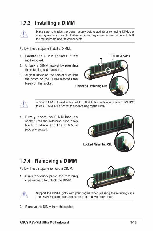
1.7.3 Installing a DIMM
Follow these steps to install a DIMM.
1. Locate the DIMM sockets in the motherboard.
2. Unlock a DIMM socket by pressing the retaining clips outward.
3. Align a DIMM on the socket such that the notch on the DIMM matches the break on the socket.
1.7.4 Removing a DIMMFollow these steps to remove a DIMM.
1. Simultaneously press the retaining clips outward to unlock the DIMM.
4. F i rmly inser t the DIMM into the socket until the retaining clips snap back in p lace and the DIMM is properly seated.
2. Remove the DIMM from the socket.
Unlocked Retaining Clip
DDR DIMM notch
Locked Retaining Clip
Make sure to unplug the power supply before adding or removing DIMMs or other system components. Failure to do so may cause severe damage to both the motherboard and the components.
A DDR DIMM is keyed with a notch so that it fits in only one direction. DO NOT force a DIMM into a socket to avoid damaging the DIMM.
Support the DIMM lightly with your fingers when pressing the retaining clips. The DIMM might get damaged when it flips out with extra force.

1-14 Chapter 1: Product Introduction
1.8 Expansion slotsIn the future, you may need to install expansion cards. The following sub-sections describe the motherboard slots and the expansion cards that they support.
1.8.1 Installing an expansion cardFollow these steps to install an expansion card.
1. Before installing the expansion card, read the documentation that came with it and make the necessary hardware settings for the card.
2. Remove the system unit cover (if your motherboard is already installed in a chassis).
3. Remove the bracket opposite the slot that you intend to use. Keep the screw for later use.
4. Align the card connector with the slot and press firmly until the card is completely seated on the slot.
5. Secure the card to the chassis with the screw you removed earlier.6. Replace the system cover.
1.8.2 Configuring an expansion cardAfter installing the expansion card, configure the card by adjusting the software settings.
1. Turn on the system and change the necessary BIOS settings, if any. See Chapter 2 for information on BIOS setup.
2. Assign an IRQ to the card. Refer to the tables on the next page.3. Install the software drivers for the expansion card.
Make sure to unplug the power cord before adding or removing expansion cards. Fai lure to do so may cause you physical in jury and damage motherboard components.
ASUS K8V-VM Ultra Motherboard 1-15
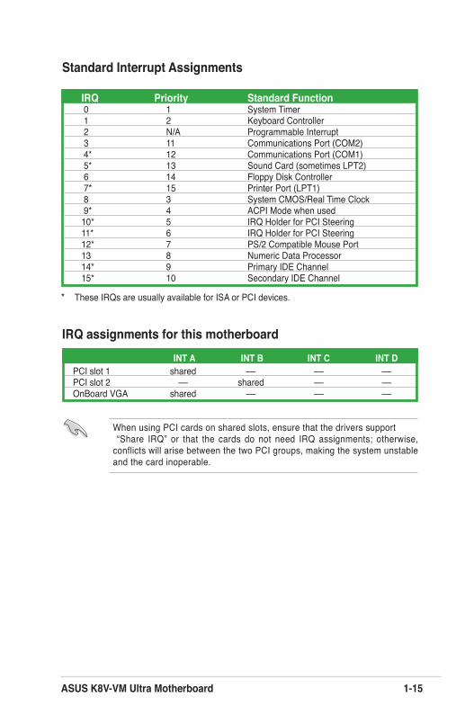
Standard Interrupt Assignments
IRQ assignments for this motherboard
When using PCI cards on shared slots, ensure that the drivers support “Share IRQ” or that the cards do not need IRQ assignments; otherwise, conflicts will arise between the two PCI groups, making the system unstable and the card inoperable.
* These IRQs are usually available for ISA or PCI devices.
IRQ Priority Standard Function 0 1 System Timer 1 2 Keyboard Controller 2 N/A Programmable Interrupt 3 11 Communications Port (COM2) 4* 12 Communications Port (COM1) 5* 13 Sound Card (sometimes LPT2) 6 14 Floppy Disk Controller 7* 15 Printer Port (LPT1) 8 3 System CMOS/Real Time Clock 9* 4 ACPI Mode when used10* 5 IRQ Holder for PCI Steering 11* 6 IRQ Holder for PCI Steering 12* 7 PS/2 Compatible Mouse Port 13 8 Numeric Data Processor 14* 9 Primary IDE Channel 15* 10 Secondary IDE Channel
INT A INT B INT C INT DPCI slot 1 shared –– –– ––PCI slot 2 –– shared –– ––OnBoard VGA shared –– –– ––
1-16 Chapter 1: Product Introduction
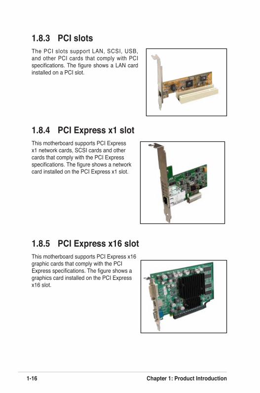
1.8.3 PCI slotsThe PCI slots support LAN, SCSI, USB, and other PCI cards that comply with PCI specifications. The figure shows a LAN card installed on a PCI slot.
1.8.4 PCI Express x1 slotThis motherboard supports PCI Express x1 network cards, SCSI cards and other cards that comply with the PCI Express specifications. The figure shows a network card installed on the PCI Express x1 slot.
1.8.5 PCI Express x16 slotThis motherboard supports PCI Express x16 graphic cards that comply with the PCI Express specifications. The figure shows a graphics card installed on the PCI Express x16 slot.
ASUS K8V-VM Ultra Motherboard 1-17
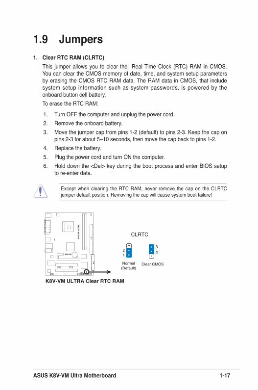
1.9 Jumpers1. Clear RTC RAM (CLRTC)
This jumper allows you to clear the Real Time Clock (RTC) RAM in CMOS. You can clear the CMOS memory of date, time, and system setup parameters by erasing the CMOS RTC RAM data. The RAM data in CMOS, that include system setup information such as system passwords, is powered by the onboard button cell battery.To erase the RTC RAM:
1. Turn OFF the computer and unplug the power cord.2. Remove the onboard battery.3. Move the jumper cap from pins 1-2 (default) to pins 2-3. Keep the cap on
pins 2-3 for about 5~10 seconds, then move the cap back to pins 1-2.4. Replace the battery.5. Plug the power cord and turn ON the computer.6. Hold down the <Del> key during the boot process and enter BIOS setup
to re-enter data.
K8V-VM ULTRA Clear RTC RAM
CLRTC
Normal Clear CMOS(Default)
12 2
3
r
R
K8V
-VM
ULT
RA
Except when clearing the RTC RAM, never remove the cap on the CLRTC jumper default position. Removing the cap will cause system boot failure!
1-18 Chapter 1: Product Introduction
K8V-VM ULTRA USB Device Wake Up
PS2_USB_PWR
(Default)+5V +5VSB
23
12
r
R
K8V
-VM
ULT
RA
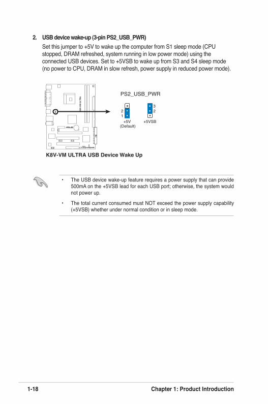
2. USB device wake-up (3-pin PS2_USB_PWR) Set this jumper to +5V to wake up the computer from S1 sleep mode (CPU
stopped, DRAM refreshed, system running in low power mode) using the connected USB devices. Set to +5VSB to wake up from S3 and S4 sleep mode (no power to CPU, DRAM in slow refresh, power supply in reduced power mode).
• The USB device wake-up feature requires a power supply that can provide 500mA on the +5VSB lead for each USB port; otherwise, the system would not power up.
• The total current consumed must NOT exceed the power supply capability (+5VSB) whether under normal condition or in sleep mode.
ASUS K8V-VM Ultra Motherboard 1-19
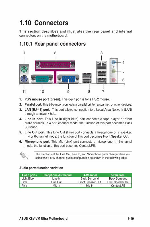
1.10 ConnectorsThis section describes and il lustrates the rear panel and internal connectors on the motherboard.
1.10.1 Rear panel connectors1
11
4
5
6
7
2 3
10 89
1. PS/2 mouse port (green). This 6-pin port is for a PS/2 mouse.2. Parallel port. This 25-pin port connects a parallel printer, a scanner, or other devices.3. LAN (RJ-45) port. This port allows connection to a Local Area Network (LAN)
through a network hub.4. Line In port. This Line In (light blue) port connects a tape player or other
audio sources. In 4 or 6-channel mode, the function of this port becomes Back Surround.
5. Line Out port. This Line Out (lime) port connects a headphone or a speaker. In 4 or 6-channel mode, the function of this port becomes Front Speaker Out.
6. Microphone port. This Mic (pink) port connects a microphone. In 6-channel mode, the function of this port becomes Center/LFE.
Audio ports function variation
Audio ports Headphone /2-Channel 4-Channel 6-ChannelLight Blue Line In Back Surround Back SurroundLime Line Out Front Speaker Out Front Speaker OutPink Mic In Mic In Center/LFE
The functions of the Line Out, Line In, and Microphone ports change when you select the 4 or 6-channel audio configuration as shown in the following table.
1-20 Chapter 1: Product Introduction
7. USB 2.0 ports 3 and 4. These two 4-pin Universal Serial Bus (USB) ports are available for connecting USB 2.0 devices.
8. USB 2.0 ports 1 and 2. These two 4-pin Universal Serial Bus (USB) ports are available for connecting USB 2.0 devices
9. Video Graphics Adapter port. This 15-pin port is for a VGA monitor or other VGA-compatible devices.
10. Serial port. This 9-pin COM1 port is for pointing devices or other serial devices.11. PS/2 keyboard port (purple). This port is for a PS/2 keyboard.
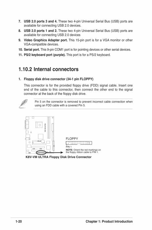
1.10.2 Internal connectors1. Floppy disk drive connector (34-1 pin FLOPPY)
This connector is for the provided floppy drive (FDD) signal cable. Insert one end of the cable to this connector, then connect the other end to the signal connector at the back of the floppy disk drive.
K8V-VM ULTRA Floppy Disk Drive Connector
NOTE: Orient the red markings onthe floppy ribbon cable to PIN 1.
PIN 1
FLOPPYr
R
K8V
-VM
ULT
RA
Pin 5 on the connector is removed to prevent incorrect cable connection when using an FDD cable with a covered Pin 5.
ASUS K8V-VM Ultra Motherboard 1-21
Single device Cable-Select or Master - Black Two devices Cable-Select Master Black Slave Gray Master Master Slave Slave
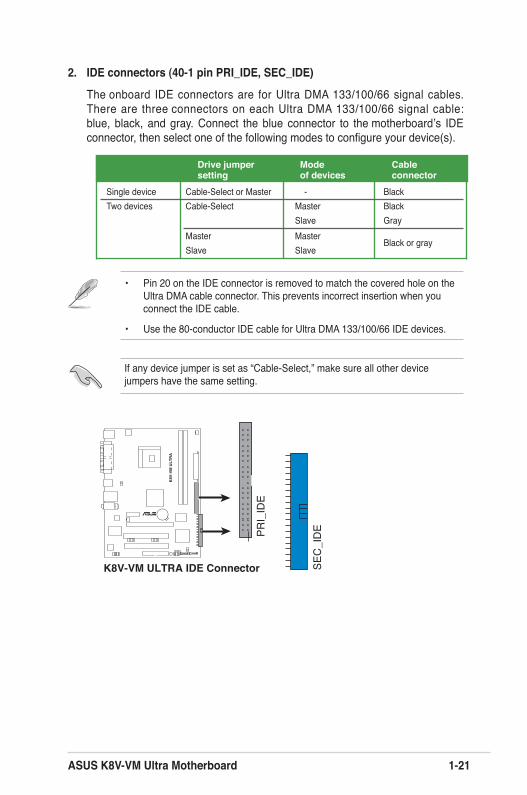
2. IDE connectors (40-1 pin PRI_IDE, SEC_IDE)
The onboard IDE connectors are for Ultra DMA 133/100/66 signal cables. There are three connectors on each Ultra DMA 133/100/66 signal cable: blue, black, and gray. Connect the blue connector to the motherboard’s IDE connector, then select one of the following modes to configure your device(s).
• Pin 20 on the IDE connector is removed to match the covered hole on the Ultra DMA cable connector. This prevents incorrect insertion when you connect the IDE cable.
• Use the 80-conductor IDE cable for Ultra DMA 133/100/66 IDE devices.
If any device jumper is set as “Cable-Select,” make sure all other device jumpers have the same setting.
K8V-VM ULTRA IDE Connector
PRI_
IDE
SEC
_ID
E
r
R
K8V
-VM
ULT
RA
Black or gray
Drive jumper Mode Cable setting of devices connector
1-22 Chapter 1: Product Introduction
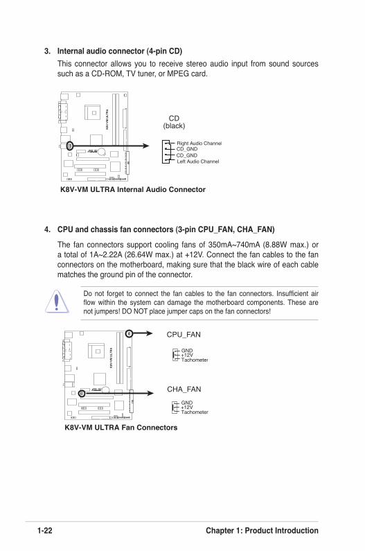
4. CPU and chassis fan connectors (3-pin CPU_FAN, CHA_FAN)
The fan connectors support cooling fans of 350mA~740mA (8.88W max.) or a total of 1A~2.22A (26.64W max.) at +12V. Connect the fan cables to the fan connectors on the motherboard, making sure that the black wire of each cable matches the ground pin of the connector.
Do not forget to connect the fan cables to the fan connectors. Insufficient air flow within the system can damage the motherboard components. These are not jumpers! DO NOT place jumper caps on the fan connectors!
K8V-VM ULTRA Fan Connectors
CHA_FAN
GND
Tachometer+12V
CPU_FAN
GND
Tachometer+12V
r
R
K8V
-VM
ULT
RA
3. Internal audio connector (4-pin CD)This connector allows you to receive stereo audio input from sound sources such as a CD-ROM, TV tuner, or MPEG card.
K8V-VM ULTRA Internal Audio Connector
CD(black)
Right Audio Channel
Left Audio ChannelCD_GNDCD_GND
r
R
K8V
-VM
ULT
RA
ASUS K8V-VM Ultra Motherboard 1-23
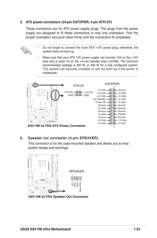
5. ATX power connectors (24-pin EATXPWR, 4-pin ATX12V)
These connectors are for ATX power supply plugs. The plugs from the power supply are designed to fit these connectors in only one orientation. Find the proper orientation and push down firmly until the connectors fit completely.
• Do not forget to connect the 4-pin ATX +12V power plug; otherwise, the
system does not boot up.
• Make sure that your ATX 12V power supply can provide 12A on the +12V lead and at least 1A on the +5-volt standby lead (+5VSB). The minimum recommended wattage is 300 W, or 350 W for a fully configured system. The system can become unstable or will not boot up if the power is inadequate.
K8V-VM ULTRA ATX Power Connector
EATXPWRATX12V
+3 Volts+3 VoltsGround+5 Volts
+5 VoltsGround
GroundPower OK
+5V Standby+12 Volts
-5 Volts
+5 Volts
+3 Volts-12 VoltsGround
GroundGroundPSON#
Ground
+5 Volts
+12 Volts+3 Volts
+5 VoltsGround
GND GND+12V DC +12V DC
r
R
K8V
-VM
ULT
RA
6. Speaker out connector (4-pin SPEAKER)This connector is for the case-mounted speaker and allows you to hear system beeps and warnings.
K8V-VM ULTRA Speaker Out Connector
SPEAKER
+5V
1
GN
DSp
eak
Out
GN
D
r
R
K8V
-VM
ULT
RA
1-24 Chapter 1: Product Introduction
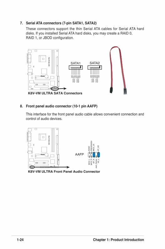
K8V-VM ULTRA Front Panel Audio Connector
r
R
K8V
-VM
ULT
RA
HP_
HD
MIC
2_L
HP_
R
HP_
L
MIC
2_JD
Jack
_Sen
se
MIC
2_R
PRES
ENSE
#AG
ND
AAFP
7. Serial ATA connectors (7-pin SATA1, SATA2)These connectors support the thin Serial ATA cables for Serial ATA hard disks. If you installed Serial ATA hard disks, you may create a RAID 0, RAID 1, or JBOD configuration.
K8V-VM ULTRA SATA Connectors
SATA2
GND
RSAT
A_TX
P2RS
ATA_
TXN2
GND
RSAT
A _RX
P2RS
ATA_
RXN2
GND
SATA1
GND
RSAT
A_TX
P1RS
ATA_
TXN1
GND
RSAT
A_RX
P1RS
ATA_
RXN1
GNDr
R
K8V
-VM
ULT
RA
8. Front panel audio connector (10-1 pin AAFP)
This interface for the front panel audio cable allows convenient connection and control of audio devices.
ASUS K8V-VM Ultra Motherboard 1-25
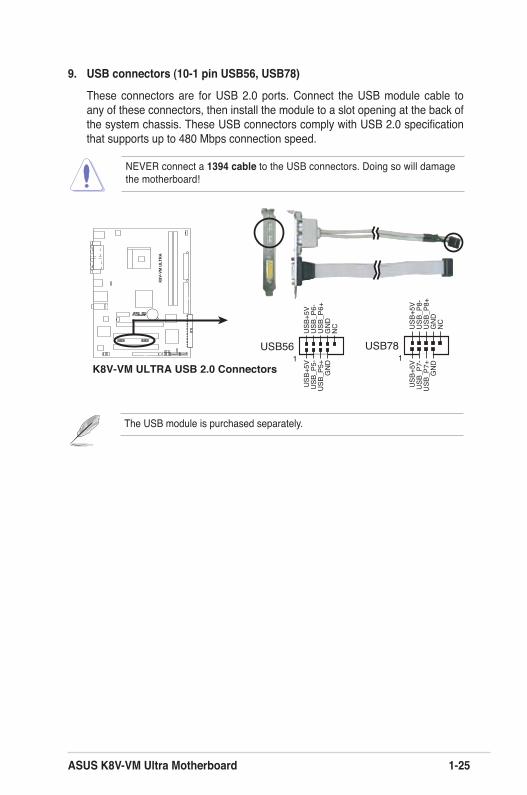
9. USB connectors (10-1 pin USB56, USB78)
These connectors are for USB 2.0 ports. Connect the USB module cable to any of these connectors, then install the module to a slot opening at the back of the system chassis. These USB connectors comply with USB 2.0 specification that supports up to 480 Mbps connection speed.
NEVER connect a 1394 cable to the USB connectors. Doing so will damage the motherboard!
The USB module is purchased separately.
K8V-VM ULTRA USB 2.0 Connectors
USB56
USB
+5V
USB
_P6-
USB
_P6+
GN
DN
C
USB
+5V
USB
_P5-
USB
_P5+
GN
D1USB78
USB
+5V
USB
_P8-
USB
_P8+
GN
DN
C
USB
+5V
USB
_P7-
USB
_P7+
GN
D1
r
R
K8V
-VM
ULT
RA
1-26 Chapter 1: Product Introduction
K8V-VM ULTRA System Panel Connector
r
R
K8V
-VM
ULT
RA
F_PANEL
PLED
-PW
R
PLED
+
Gro
und
GN
DR
eset
IDEL
ED+
IDEL
ED-
HD LED RESET
PLED PWRSW
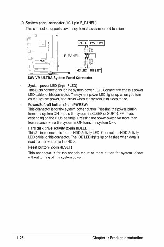
10. System panel connector (10-1 pin F_PANEL)This connector supports several system chassis-mounted functions.
• System power LED (2-pin PLED) This 3-pin connector is for the system power LED. Connect the chassis power LED cable to this connector. The system power LED lights up when you turn on the system power, and blinks when the system is in sleep mode.
• Power/Soft-off button (2-pin PWRSW) This connector is for the system power button. Pressing the power button turns the system ON or puts the system in SLEEP or SOFT-OFF mode depending on the BIOS settings. Pressing the power switch for more than four seconds while the system is ON turns the system OFF.
• Hard disk drive activity (2-pin HDLED) This 2-pin connector is for the HDD Activity LED. Connect the HDD Activity LED cable to this connector. The IDE LED lights up or flashes when data is read from or written to the HDD.
• Reset button (2-pin RESET) This connector is for the chassis-mounted reset button for system reboot
without turning off the system power.
Chapter 2
This chapter tells how to change system settings through the BIOS Setup menus, and provides detailed descriptions of the BIOS parameters.
BIOS Information
2-2 Chapter 2: BIOS Information
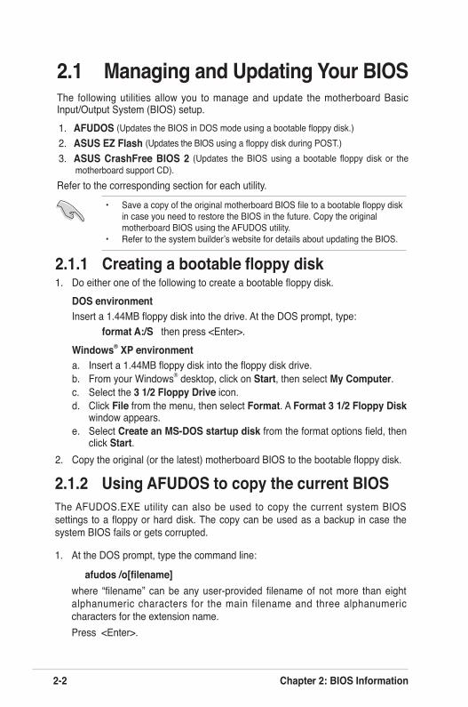
2.1 Managing and Updating Your BIOSThe following utilities allow you to manage and update the motherboard Basic Input/Output System (BIOS) setup.1. AFUDOS (Updates the BIOS in DOS mode using a bootable floppy disk.)2. ASUS EZ Flash (Updates the BIOS using a floppy disk during POST.) 3. ASUS CrashFree BIOS 2 (Updates the BIOS using a bootable floppy disk or the
motherboard support CD).Refer to the corresponding section for each utility.
2.1.1 Creating a bootable floppy disk1. Do either one of the following to create a bootable floppy disk.
DOS environmentInsert a 1.44MB floppy disk into the drive. At the DOS prompt, type:
format A:/S then press <Enter>.Windows® XP environmenta. Insert a 1.44MB floppy disk into the floppy disk drive. b. From your Windows® desktop, click on Start, then select My Computer. c. Select the 3 1/2 Floppy Drive icon.d. Click File from the menu, then select Format. A Format 3 1/2 Floppy Disk
window appears.e. Select Create an MS-DOS startup disk from the format options field, then
click Start.2. Copy the original (or the latest) motherboard BIOS to the bootable floppy disk.
2.1.2 Using AFUDOS to copy the current BIOSThe AFUDOS.EXE utility can also be used to copy the current system BIOS settings to a floppy or hard disk. The copy can be used as a backup in case the system BIOS fails or gets corrupted.
1. At the DOS prompt, type the command line:
afudos /o[filename]where “filename” can be any user-provided filename of not more than eight alphanumeric characters for the main filename and three alphanumeric characters for the extension name. Press <Enter>.
• Save a copy of the original motherboard BIOS file to a bootable floppy disk in case you need to restore the BIOS in the future. Copy the original motherboard BIOS using the AFUDOS utility. • Refer to the system builder’s website for details about updating the BIOS.
ASUS K8V-VM Ultra Motherboard 2-3
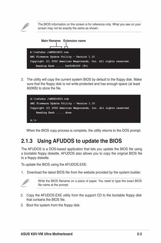
2. The utility will copy the current system BIOS by default to the floppy disk. Make sure that the floppy disk is not write-protected and has enough space (at least 600KB) to store the file.
The BIOS information on the screen is for reference only. What you see on your screen may not be exactly the same as shown.
When the BIOS copy process is complete, the utility returns to the DOS prompt.
A:\>afudos /oMYBIOS03.rom
AMI Firmware Update Utility - Version 1.10
Copyright (C) 2002 American Megatrends, Inc. All rights reserved.
Reading flash ..... done
A:\>
2.1.3 Using AFUDOS to update the BIOSThe AFUDOS is a DOS-based application that lets you update the BIOS file using a bootable floppy diskette. AFUDOS also allows you to copy the original BIOS file to a floppy diskette.
To update the BIOS using the AFUDOS.EXE:
1. Download the latest BIOS file from the website provided by the system builder.
Main filename Extension name
A:\>afudos /oMYBIOS03.rom
AMI Firmware Update Utility - Version 1.10
Copyright (C) 2002 American Megatrends, Inc. All rights reserved.
Reading flash ..... 0x0008CC00 (9%)
Write the BIOS filename on a piece of paper. You need to type the exact BIOS file name at the prompt.
2. Copy the AFUDOS.EXE utility from the support CD to the bootable floppy disk that contains the BIOS file.
3. Boot the system from the floppy disk.
2-4 Chapter 2: BIOS Information
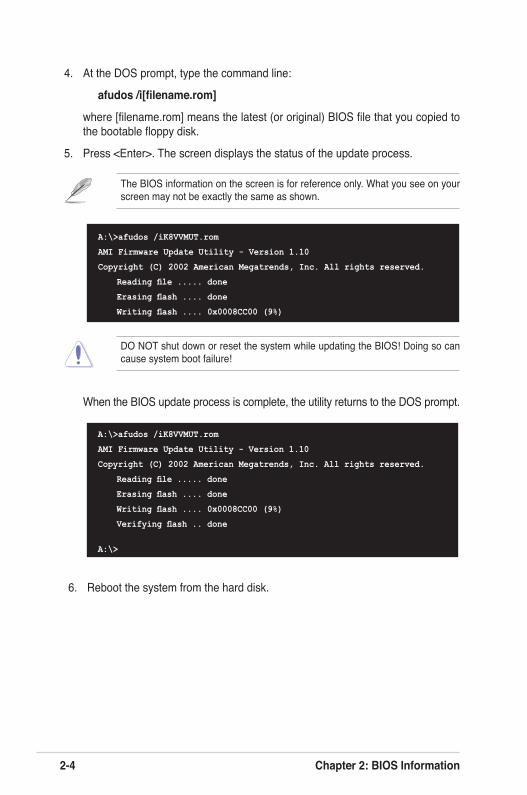
4. At the DOS prompt, type the command line:
afudos /i[filename.rom]
where [filename.rom] means the latest (or original) BIOS file that you copied to the bootable floppy disk.
5. Press <Enter>. The screen displays the status of the update process.
A:\>afudos /iK8VVMUT.rom
AMI Firmware Update Utility - Version 1.10
Copyright (C) 2002 American Megatrends, Inc. All rights reserved.
Reading file ..... done
Erasing flash .... done
Writing flash .... 0x0008CC00 (9%)
When the BIOS update process is complete, the utility returns to the DOS prompt.
A:\>afudos /iK8VVMUT.rom
AMI Firmware Update Utility - Version 1.10
Copyright (C) 2002 American Megatrends, Inc. All rights reserved.
Reading file ..... done
Erasing flash .... done
Writing flash .... 0x0008CC00 (9%)
Verifying flash .. done
A:\>
DO NOT shut down or reset the system while updating the BIOS! Doing so can cause system boot failure!
The BIOS information on the screen is for reference only. What you see on your screen may not be exactly the same as shown.
6. Reboot the system from the hard disk.
ASUS K8V-VM Ultra Motherboard 2-5
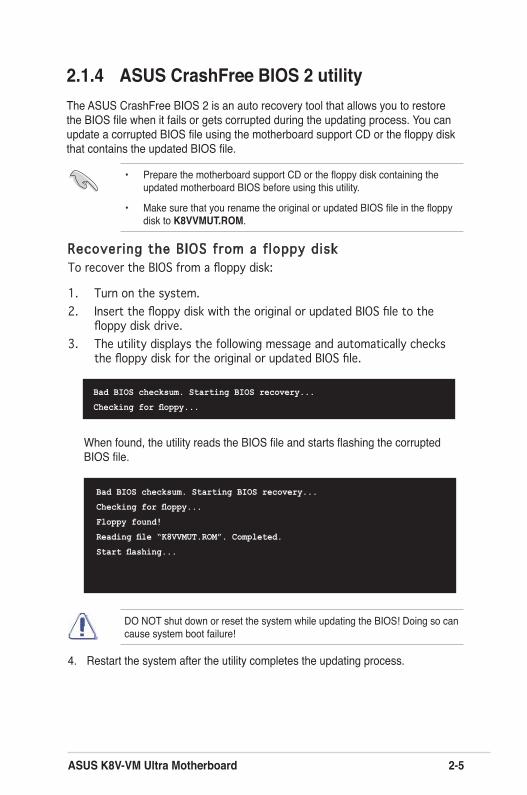
2.1.4 ASUS CrashFree BIOS 2 utilityThe ASUS CrashFree BIOS 2 is an auto recovery tool that allows you to restore the BIOS file when it fails or gets corrupted during the updating process. You can update a corrupted BIOS file using the motherboard support CD or the floppy disk that contains the updated BIOS file.
When found, the utility reads the BIOS file and starts flashing the corrupted BIOS file.
4. Restart the system after the utility completes the updating process.
DO NOT shut down or reset the system while updating the BIOS! Doing so can cause system boot failure!
Bad BIOS checksum. Starting BIOS recovery...
Checking for floppy...
• Prepare the motherboard support CD or the floppy disk containing the updated motherboard BIOS before using this utility.
• Make sure that you rename the original or updated BIOS file in the floppy disk to K8VVMUT.ROM.
Recovering the BIOS from a f loppy diskTo recover the BIOS from a floppy disk:
1. Turn on the system.2. Insert the floppy disk with the original or updated BIOS file to the
floppy disk drive.3. The utility displays the following message and automatically checks
the floppy disk for the original or updated BIOS file.
Bad BIOS checksum. Starting BIOS recovery...
Checking for floppy...
Floppy found!
Reading file “K8VVMUT.ROM”. Completed.
Start flashing...
2-6 Chapter 2: BIOS Information
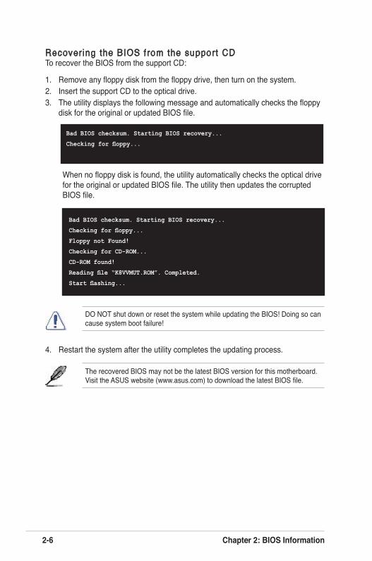
Recover ing the BIOS from the support CDTo recover the BIOS from the support CD:
1. Remove any floppy disk from the floppy drive, then turn on the system.2. Insert the support CD to the optical drive.3. The utility displays the following message and automatically checks the floppy
disk for the original or updated BIOS file.
When no floppy disk is found, the utility automatically checks the optical drive for the original or updated BIOS file. The utility then updates the corrupted BIOS file.
The recovered BIOS may not be the latest BIOS version for this motherboard. Visit the ASUS website (www.asus.com) to download the latest BIOS file.
4. Restart the system after the utility completes the updating process.
DO NOT shut down or reset the system while updating the BIOS! Doing so can cause system boot failure!
Bad BIOS checksum. Starting BIOS recovery...
Checking for floppy...
Bad BIOS checksum. Starting BIOS recovery...
Checking for floppy...
Floppy not Found!
Checking for CD-ROM...
CD-ROM found!
Reading file “K8VVMUT.ROM”. Completed.
Start flashing...
ASUS K8V-VM Ultra Motherboard 2-7
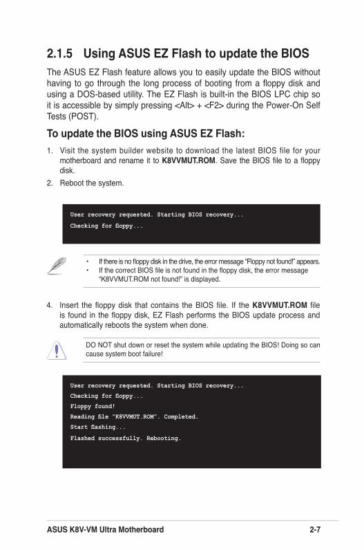
2.1.5 Using ASUS EZ Flash to update the BIOSThe ASUS EZ Flash feature allows you to easily update the BIOS without having to go through the long process of booting from a floppy disk and using a DOS-based utility. The EZ Flash is built-in the BIOS LPC chip so it is accessible by simply pressing <Alt> + <F2> during the Power-On Self Tests (POST).
To update the BIOS using ASUS EZ Flash:1. Visit the system builder website to download the latest BIOS file for your
motherboard and rename it to K8VVMUT.ROM. Save the BIOS file to a floppy disk.
2. Reboot the system.
4. Insert the floppy disk that contains the BIOS file. If the K8VVMUT.ROM file is found in the floppy disk, EZ Flash performs the BIOS update process and automatically reboots the system when done.
DO NOT shut down or reset the system while updating the BIOS! Doing so can cause system boot failure!
User recovery requested. Starting BIOS recovery...
Checking for floppy...
Floppy found!
Reading file “K8VVMUT.ROM”. Completed.
Start flashing...
Flashed successfully. Rebooting.
User recovery requested. Starting BIOS recovery...
Checking for floppy...
• If there is no floppy disk in the drive, the error message “Floppy not found!” appears. • If the correct BIOS file is not found in the floppy disk, the error message “K8VVMUT.ROM not found!” is displayed.
2-8 Chapter 2: BIOS Information
2.2 BIOS Setup ProgramThe BIOS software is constantly being updated so the BIOS setup screens and descriptions in this section are for reference purposes only, and may not exactly match what you see on your screen.
This motherboard supports a programmable Low Pin Count (LPC) chip that you can update using the provided utility described in section “2.1 Managing and updating your BIOS.”
Use the BIOS Setup program when you are installing a motherboard, reconfiguring your system, or prompted to “Run Setup”. This section explains how to configure your system using this utility.
Even if you are not prompted to use the Setup program, you can change the configuration of your computer in the future. For example, you can enable the security password feature or make changes to the power management settings. This requires you to reconfigure your system using the BIOS Setup program so that the computer can recognize these changes and record them in the CMOS RAM of the LPC chip.
The LPC chip on the motherboard stores the Setup utility. When you start up the computer, the system provides you with the opportunity to run this program. Press <Del> during the Power-On Self-Test (POST) to enter the Setup utility; otherwise, POST continues with its test routines.
To enter Setup after POST, restart the system by pressing <Ctrl> + <Alt> + <Del>, or by pressing the reset button on the system chassis. You can also restart by turning the system off and then back on. Do this last option only if the first two fail.
The Setup program is designed to make it as easy to use as possible. Being a menu-driven program, it lets you scroll through the various sub-menus and make your selections among the predetermined choices.
ASUS K8V-VM Ultra Motherboard 2-9
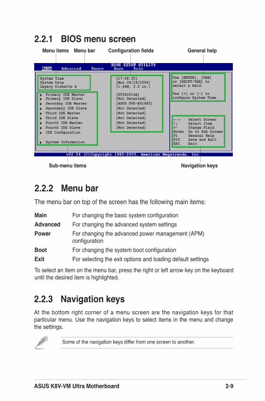
Use [ENTER], [TAB] or [SHIFT-TAB] toselect a field.
Use [+] or [-] toconfigure System Time.
Some of the navigation keys differ from one screen to another.
2.2.2 Menu barThe menu bar on top of the screen has the following main items:
Main For changing the basic system configurationAdvanced For changing the advanced system settingsPower For changing the advanced power management (APM)
configurationBoot For changing the system boot configurationExit For selecting the exit options and loading default settings
To select an item on the menu bar, press the right or left arrow key on the keyboard until the desired item is highlighted.
2.2.1 BIOS menu screen
2.2.3 Navigation keysAt the bottom right corner of a menu screen are the navigation keys for that particular menu. Use the navigation keys to select items in the menu and change the settings.
Navigation keys
General helpMenu bar
Sub-menu items
Configuration fieldsMenu items
v02.54 (C)Copyright 1985-2003, American Megatrends, Inc.
System Time [17:08:35]System Date [Mon 04/19/2004]Legacy Diskette A [1.44M, 3.5 in.]
Primary IDE Master [ST340014A] Primary IDE Slave [Not Detected] Seconday IDE Master [ASUS DVD-E616P2] Secondary IDE Slave [Not Detected] Third IDE Master [Not Detected] Third IDE Slave [Not Detected] Fourth IDE Master [Not Detected] Fourth IDE Slave [Not Detected] IDE Configuration
System Information
←→ Select Screen↑↓ Select Item+- Change FieldEnter Go to Sub ScreenF1 General HelpF10 Save and ExitESC Exit
2-10 Chapter 2: BIOS Information
2.2.4 Menu itemsThe highlighted item on the menu bar displays the specific items for that menu. For example, selecting Main shows the Main menu items.
The other items (Advanced, Power, Boot, and Exit) on the menu bar have their respective menu items.
2.2.5 Sub-menu itemsA solid triangle before each item on any menu screen means that the item has a sub-menu. To display the sub-menu, select the item, then press <Enter>.
2.2.6 Configuration fieldsThese fields show the values for the menu items. If an item is user-configurable, you can change the value of the field opposite the item. You cannot select an item that is not user-configurable.
A configurable field is enclosed in brackets, and is highlighted when selected. To change the value of a field, select it then press <Enter> to display a list of options. Refer to “2.2.7 Pop-up window”.
2.2.7 Pop-up windowSelect a menu item then press <Enter> to display a pop-up window with the configuration options for that item.
2.2.8 Scroll barA scroll bar appears on the right side of a menu screen when there are items that do not fit on the screen. Press the Up/Down arrow keys or <PageUp> / <PageDown> keys to display the other items on the screen.
2.2.9 General helpAt the top right corner of the menu screen is a brief description of the selected item.
ASUS K8V-VM Ultra Motherboard 2-11
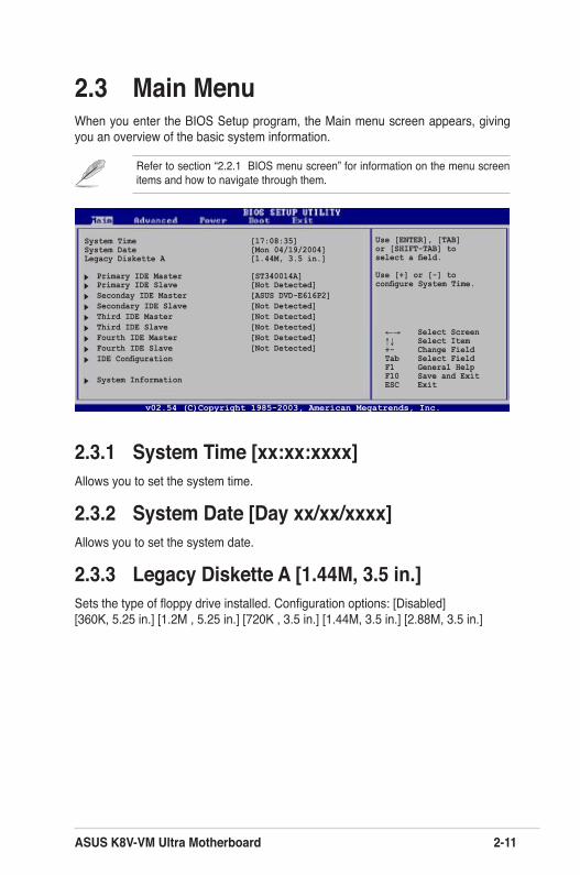
2.3 Main MenuWhen you enter the BIOS Setup program, the Main menu screen appears, giving you an overview of the basic system information.
2.3.1 System Time [xx:xx:xxxx]Allows you to set the system time.
2.3.2 System Date [Day xx/xx/xxxx]Allows you to set the system date.
2.3.3 Legacy Diskette A [1.44M, 3.5 in.]Sets the type of floppy drive installed. Configuration options: [Disabled] [360K, 5.25 in.] [1.2M , 5.25 in.] [720K , 3.5 in.] [1.44M, 3.5 in.] [2.88M, 3.5 in.]
Refer to section “2.2.1 BIOS menu screen” for information on the menu screen items and how to navigate through them.
Use [ENTER], [TAB] or [SHIFT-TAB] toselect a field.
Use [+] or [-] toconfigure System Time.
v02.54 (C)Copyright 1985-2003, American Megatrends, Inc.
←→ Select Screen↑↓ Select Item+- Change FieldTab Select FieldF1 General HelpF10 Save and ExitESC Exit
System Time [17:08:35]System Date [Mon 04/19/2004]Legacy Diskette A [1.44M, 3.5 in.]
Primary IDE Master [ST340014A] Primary IDE Slave [Not Detected] Seconday IDE Master [ASUS DVD-E616P2] Secondary IDE Slave [Not Detected] Third IDE Master [Not Detected] Third IDE Slave [Not Detected] Fourth IDE Master [Not Detected] Fourth IDE Slave [Not Detected] IDE Configuration
System Information
2-12 Chapter 2: BIOS Information
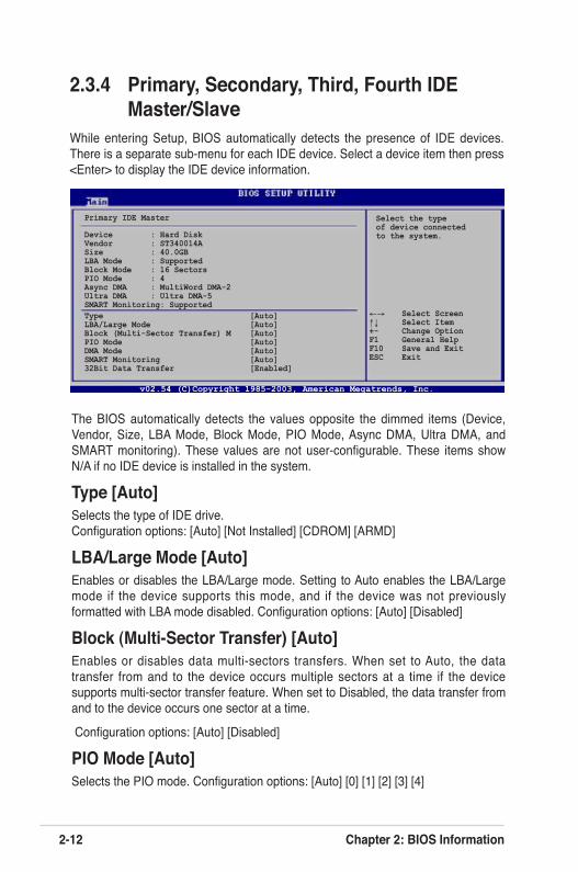
2.3.4 Primary, Secondary, Third, Fourth IDE Master/Slave
While entering Setup, BIOS automatically detects the presence of IDE devices. There is a separate sub-menu for each IDE device. Select a device item then press <Enter> to display the IDE device information.
The BIOS automatically detects the values opposite the dimmed items (Device, Vendor, Size, LBA Mode, Block Mode, PIO Mode, Async DMA, Ultra DMA, and SMART monitoring). These values are not user-configurable. These items show N/A if no IDE device is installed in the system.
Type [Auto]Selects the type of IDE drive. Configuration options: [Auto] [Not Installed] [CDROM] [ARMD]
LBA/Large Mode [Auto]Enables or disables the LBA/Large mode. Setting to Auto enables the LBA/Large mode if the device supports this mode, and if the device was not previously formatted with LBA mode disabled. Configuration options: [Auto] [Disabled]
Block (Multi-Sector Transfer) [Auto]Enables or disables data multi-sectors transfers. When set to Auto, the data transfer from and to the device occurs multiple sectors at a time if the device supports multi-sector transfer feature. When set to Disabled, the data transfer from and to the device occurs one sector at a time.
Configuration options: [Auto] [Disabled]
PIO Mode [Auto]Selects the PIO mode. Configuration options: [Auto] [0] [1] [2] [3] [4]
Primary IDE Master
Device : Hard DiskVendor : ST340014ASize : 40.0GBLBA Mode : SupportedBlock Mode : 16 SectorsPIO Mode : 4Async DMA : MultiWord DMA-2Ultra DMA : Ultra DMA-5 SMART Monitoring: Supported
Select the typeof device connected to the system.
Type [Auto]LBA/Large Mode [Auto]Block (Multi-Sector Transfer) M [Auto]PIO Mode [Auto]DMA Mode [Auto]SMART Monitoring [Auto]32Bit Data Transfer [Enabled]
v02.54 (C)Copyright 1985-2003, American Megatrends, Inc.
←→ Select Screen↑↓ Select Item+- Change OptionF1 General HelpF10 Save and ExitESC Exit
ASUS K8V-VM Ultra Motherboard 2-13
DMA Mode [Auto]Selects the DMA mode. Configuration options: [Auto] [SWDMA0] [SWDMA1] [SWDMA2] [MWDMA0] [MWDMA1] [MWDMA2] [UDMA0] [UDMA1] [UDMA2] [UDMA3] [UDMA4] [UDMA5]
SMART Monitoring [Auto]Sets the Smart Monitoring, Analysis, and Reporting Technology. Configuration options: [Auto] [Disabled] [Enabled]
32Bit Data Transfer [Disabled]Enables or disables 32-bit data transfer. Configuration options: [Disabled] [Enabled]
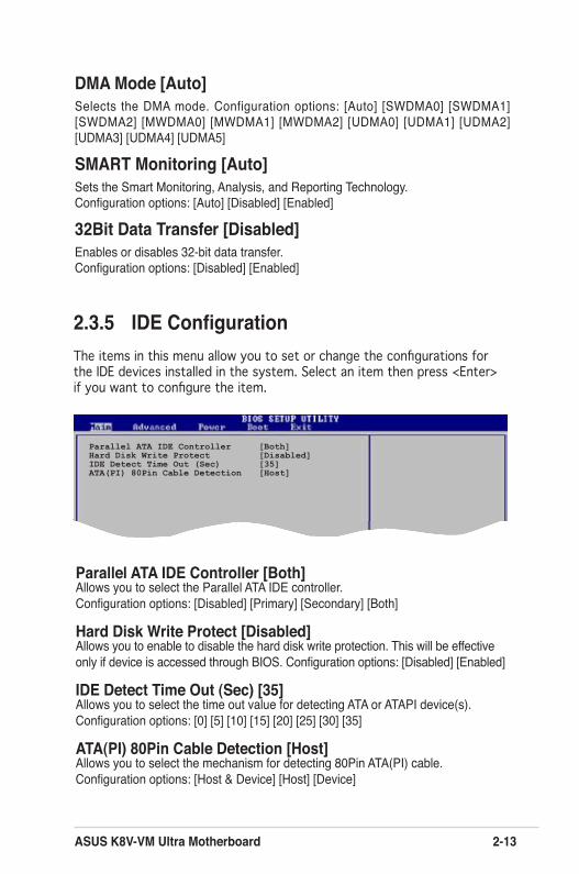
2.3.5 IDE ConfigurationThe items in this menu allow you to set or change the configurations for the IDE devices installed in the system. Select an item then press <Enter> if you want to configure the item.
Parallel ATA IDE Controller [Both]Hard Disk Write Protect [Disabled]IDE Detect Time Out (Sec) [35]ATA(PI) 80Pin Cable Detection [Host]
Parallel ATA IDE Controller [Both]Allows you to select the Parallel ATA IDE controller. Configuration options: [Disabled] [Primary] [Secondary] [Both]
Hard Disk Write Protect [Disabled]Allows you to enable to disable the hard disk write protection. This will be effective only if device is accessed through BIOS. Configuration options: [Disabled] [Enabled]
IDE Detect Time Out (Sec) [35]Allows you to select the time out value for detecting ATA or ATAPI device(s).Configuration options: [0] [5] [10] [15] [20] [25] [30] [35]
ATA(PI) 80Pin Cable Detection [Host]Allows you to select the mechanism for detecting 80Pin ATA(PI) cable. Configuration options: [Host & Device] [Host] [Device]
2-14 Chapter 2: BIOS Information
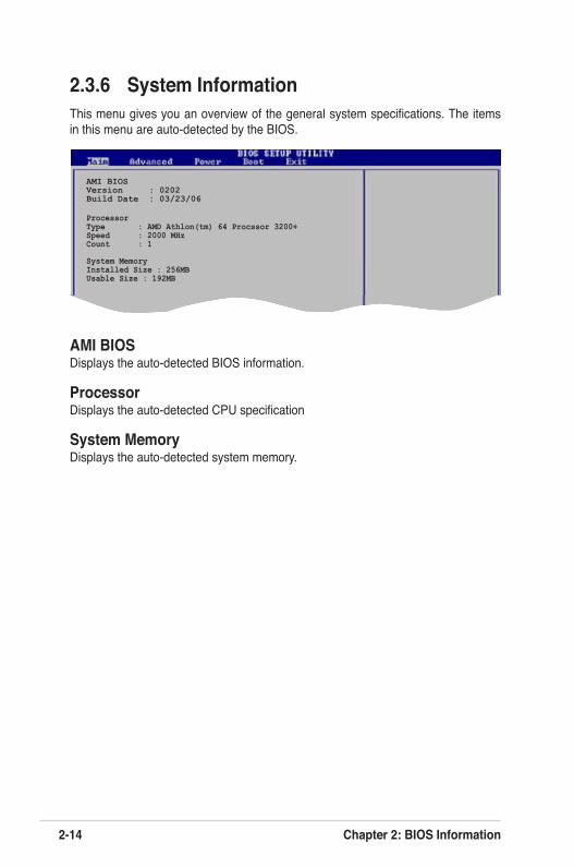
2.3.6 System InformationThis menu gives you an overview of the general system specifications. The items in this menu are auto-detected by the BIOS.
AMI BIOSDisplays the auto-detected BIOS information.
ProcessorDisplays the auto-detected CPU specification
System MemoryDisplays the auto-detected system memory.
AMI BIOSVersion : 0202Build Date : 03/23/06
ProcessorType : AMD Athlon(tm) 64 Procssor 3200+Speed : 2000 MHzCount : 1
System MemoryInstalled Size : 256MBUsable Size : 192MB
ASUS K8V-VM Ultra Motherboard 2-15
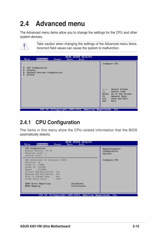
2.4 Advanced menuThe Advanced menu items allow you to change the settings for the CPU and other system devices.
Take caution when changing the settings of the Advanced menu items. Incorrect field values can cause the system to malfunction.
2.4.1 CPU ConfigurationThe items in this menu show the CPU-related information that the BIOS automatically detects.
HyperTransportConfigurationOptions
CPU ConfigurationChipsetOnboard Devices ConfigurationPCIPnP
Configure CPU.
v02.54 (C)Copyright 1985-2003, American Megatrends, Inc.
←→ Select Screen↑↓ Select ItemEnter Go to Sub ScreenF1 General HelpF10 Save and ExitESC Exit
Configure CPU.
CPU ConfigurationModule Version: 14.08Physical Count: 1Logical Count : 1
AMD Athlon(tm) 64 Processor 3200+Revision: C0Cache L1: 128KBCache L2: 1024KBSpeed : 2000MHzCurrent FSB Multiplier: 10xMaximum FSB Multiplier: 10xAble to Change Freq. : YesuCode Patch Level : 0x39
GART Error Reporting [Disabled]MTRR Mapping [Continuous]
V02.54 (C)Copyright 1985-2003, American Megatrends, Inc.
2-16 Chapter 2: BIOS Information
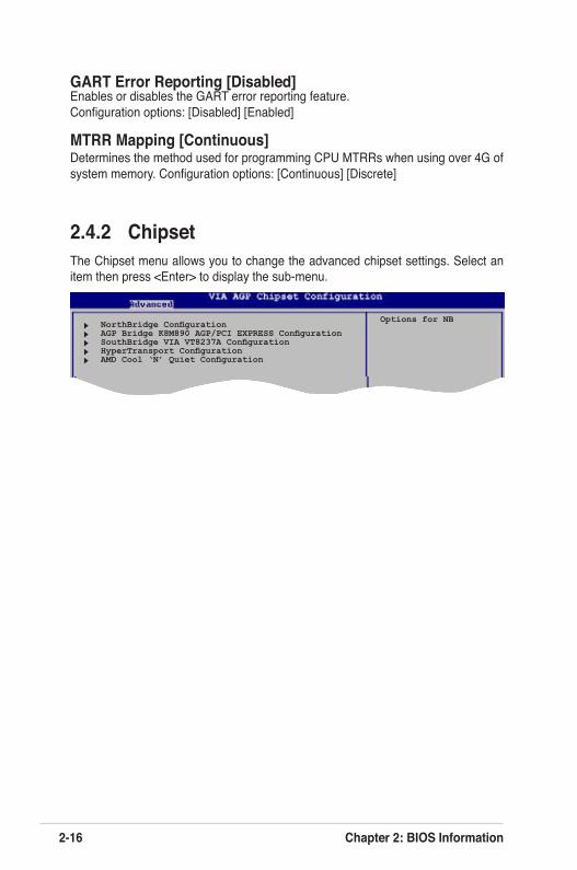
GART Error Reporting [Disabled]Enables or disables the GART error reporting feature. Configuration options: [Disabled] [Enabled]
MTRR Mapping [Continuous]Determines the method used for programming CPU MTRRs when using over 4G of system memory. Configuration options: [Continuous] [Discrete]
2.4.2 ChipsetThe Chipset menu allows you to change the advanced chipset settings. Select an item then press <Enter> to display the sub-menu.
NorthBridge Configuration AGP Bridge K8M890 AGP/PCI EXPRESS Configuration SouthBridge VIA VT8237A Configuration HyperTransport Configuration AMD Cool ‘N’ Quiet Configuration
Options for NB
ASUS K8V-VM Ultra 2-17
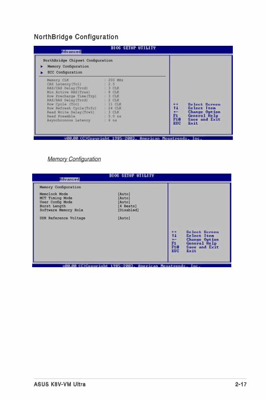
NorthBridge Conf igurat ion
Memory Configuration
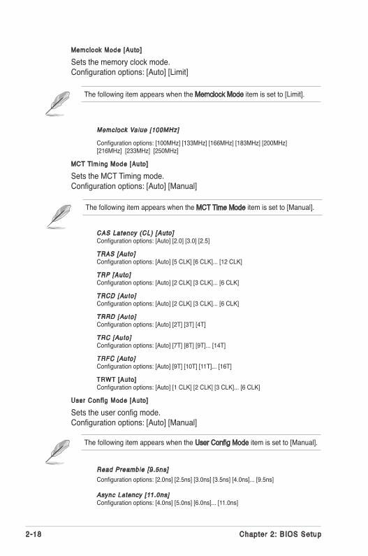
Memclock Mode [Auto]MCT Timing Mode [Auto]User Config Mode [Auto]Burst Length [4 Beats]Software Memory Hole [Disabled]
DDR Reference Voltage [Auto]
Memory Configuration
NorthBridge Chipset Configuration Memory Configuration ECC Configuration
Memory CLK : 200 MHz CAS Latency(Tcl) : 2.5 RAS/CAS Delay(Trcd) : 3 CLK Min Active RAS(Tras) : 8 CLK Row Precharge Time(Trp) : 3 CLK RAS/RAS Delay(Trrd) : 2 CLK Row Cycle (Trc) : 11 CLK Row Refresh Cycle(Trfc) : 24 CLK Read Write Delay(Trwt) : 3 CLK Read Preamble : 5.0 ns Asynchronous Latency : 6 ns
2-18 Chapter 2: BIOS Setup
Memclock Value [100MHz]
Configuration options: [100MHz] [133MHz] [166MHz] [183MHz] [200MHz] [216MHz] [233MHz] [250MHz]
MCT Timing Mode [Auto]
Sets the MCT Timing mode. Configuration options: [Auto] [Manual]
CAS Latency (CL) [Auto] Configuration options: [Auto] [2.0] [3.0] [2.5]
TRAS [Auto] Configuration options: [Auto] [5 CLK] [6 CLK]... [12 CLK]
TRP [Auto] Configuration options: [Auto] [2 CLK] [3 CLK]... [6 CLK]
TRCD [Auto] Configuration options: [Auto] [2 CLK] [3 CLK]... [6 CLK]
TRRD [Auto] Configuration options: [Auto] [2T] [3T] [4T]
TRC [Auto] Configuration options: [Auto] [7T] [8T] [9T]... [14T]
TRFC [Auto] Configuration options: [Auto] [9T] [10T] [11T]... [16T]
TRWT [Auto] Configuration options: [Auto] [1 CLK] [2 CLK] [3 CLK]... [6 CLK]
User Conf ig Mode [Auto]
Sets the user config mode. Configuration options: [Auto] [Manual]
Read Preamble [9.5ns] Configuration options: [2.0ns] [2.5ns] [3.0ns] [3.5ns] [4.0ns]... [9.5ns]
Async Latency [11.0ns] Configuration options: [4.0ns] [5.0ns] [6.0ns]... [11.0ns]
Memclock Mode [Auto]
Sets the memory clock mode. Configuration options: [Auto] [Limit]
The following item appears when the Memclock Mode item is set to [Limit].
The following item appears when the MCT Time Mode item is set to [Manual].
The following item appears when the User Config Mode item is set to [Manual].
ASUS K8V-VM Ultra 2-19
CMD-ADDR Timing Mode [2T] Configuration options: [1T] [2T]
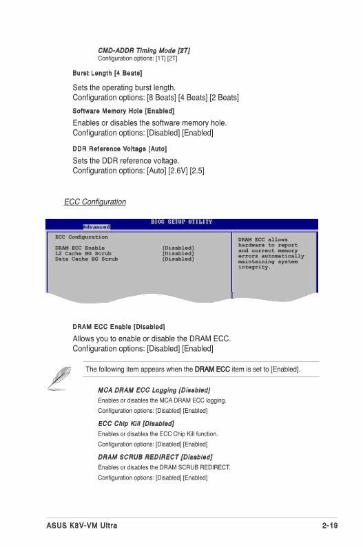
ECC Configuration
DRAM ECC Enable [Disabled]
Allows you to enable or disable the DRAM ECC. Configuration options: [Disabled] [Enabled]
ECC Configuration
DRAM ECC Enable [Disabled]L2 Cache BG Scrub [Disabled]Data Cache BG Scrub [Disabled]
MCA DRAM ECC Logging [Disabled]Enables or disables the MCA DRAM ECC logging. Configuration options: [Disabled] [Enabled]
ECC Chip Ki l l [Disabled]Enables or disables the ECC Chip Kill function.Configuration options: [Disabled] [Enabled]
DRAM SCRUB REDIRECT [Disabled]Enables or disables the DRAM SCRUB REDIRECT. Configuration options: [Disabled] [Enabled]
DRAM ECC allowshardware to reportand correct memoryerrors automaticallymaintaining systemintegrity.
Burst Length [4 Beats]
Sets the operating burst length. Configuration options: [8 Beats] [4 Beats] [2 Beats]Software Memory Hole [Enabled]
Enables or disables the software memory hole. Configuration options: [Disabled] [Enabled]
DDR Reference Vol tage [Auto]
Sets the DDR reference voltage. Configuration options: [Auto] [2.6V] [2.5]
The following item appears when the DRAM ECC item is set to [Enabled].
2-20 Chapter 2: BIOS Setup
DRAM BG SCRUB [Disabled]Disables or sets the DRAM BG SCRUB. Configuration options: [Disabled] [40ns] [80ns] [160ns] [320ns] [640ns] [1.28us] [2.56us] [5.12us] [10.2us] [20.5us] [41.0us] [81.9us] [163.8us] [327.7us] [655.4us] [1.31ms] [2.62ms] [5.24ms] [10.49ms] [20.97ms] [42.00ms] [84.00ms]
L2 Cache BG Scrub [Disabled]
Disables or sets the L2 Cache BG Scrub. Configuration options: [Disabled] [40ns] [80ns] [160ns] [320ns] [640ns] [1.28us] [2.56us] [5.12us] [10.2us] [20.5us] [41.0us] [81.9us] [163.8us] [327.7us] [655.4us] [1.31ms] [2.62ms] [5.24ms] [10.49ms] [20.97ms] [42.00ms] [84.00ms]
Data Cache BG Scrub [Disabled]
Disables or sets the Data Cache BG Scrub. Configuration options: [Disabled] [40ns] [80ns] [160ns] [320ns] [640ns] [1.28us] [2.56us] [5.12us] [10.2us] [20.5us] [41.0us] [81.9us] [163.8us] [327.7us] [655.4us] [1.31ms] [2.62ms] [5.24ms] [10.49ms] [20.97ms] [42.00ms] [84.00ms]
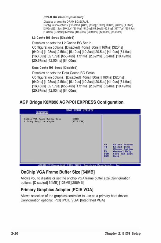
OnChip VGA Frame Buffer Size [64MB]Allows you to disable or set the onchip VGA frame buffer size.Configuration options: [Disabled] 64MB] [128MB][256MB]
Primary Graphics Adapter [PCIE VGA]Allows selection of the graphics controller to use as a primary boot device.Configuration options: [PCI] [PCIE VGA] [Integrated VGA]
AGP Bridge K8M890 AGP/PCI EXPRESS Configuration
OnChip VGA Frame Buffer Size [64MB]Primary Graphics Adapter [PCIE VGA]
ASUS K8V-VM Ultra 2-21
Options
DisabledIDERAID
Serial ATA IDE Controller [IDE]LAN Controller [Enabled] LAN BOOTROM [Disabled]High Definition Audio [Auto]USB 1.1 Ports Configuration [USB 8 Ports] Lagacy USB Support [Enabled]USB 2.0 Ports Enable [Enable]
PCI Delay Transaction [Enabled]
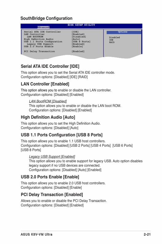
SouthBridge Configuration
Serial ATA IDE Controller [IDE]This option allows you to set the Serial ATA IDE controller mode. Configuration options: [Disabled] [IDE] [RAID]
LAN Controller [Enabled]This option allows you to enable or disable the LAN controller. Configuration options: [Disabled] [Enabled]
LAN BootROM [Disabled]This option allows you to enable or disable the LAN boot ROM. Configuration options: [Disabled] [Enabled]
High Definition Audio [Auto]This option allows you to set the High Definition Audio. Configuration options: [Disabled] [Auto]
USB 1.1 Ports Configuration [USB 8 Ports]This option allows you to enable 1.1 USB host controllers. Configuration options: [Disabled] [USB 2 Ports] [USB 4 Ports] [USB 6 Ports] [USB 8 Ports]
Legacy USB Support [Enabled]This option allows you to enable support for legacy USB. Auto option disables legacy support if no USB devices are connected. Configuration options: [Disabled] [Auto] [Enabled]
USB 2.0 Ports Enable [Enable]This option allows you to enable 2.0 USB host controllers. Configuration options: [Disabled] [Enable]
PCI Delay Transaction [Enabled]Allows you to enable or disable the PCI Delay Transaction. Configuration options: [Disabled] [Enabled]
2-22 Chapter 2: BIOS Setup
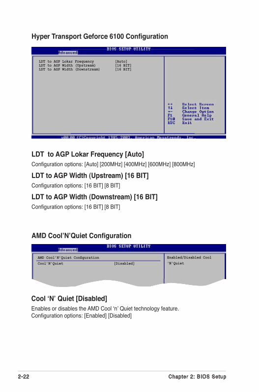
Hyper Transport Geforce 6100 Configuration
LDT to AGP Lokar Frequency [Auto]Configuration options: [Auto] [200MHz] [400MHz] [600MHz] [800MHz]
LDT to AGP Width (Upstream) [16 BIT]Configuration options: [16 BIT] [8 BIT]
LDT to AGP Width (Downstream) [16 BIT]Configuration options: [16 BIT] [8 BIT]
LDT to AGP Lokar Frequency [Auto]LDT to AGP Width (Upstream) [16 BIT]LDT to AGP Width (Downstream) [16 BIT]
AMD Cool’N’Quiet ConfigurationCool’N’Quiet [Disabled]
Cool ‘N’ Quiet [Disabled]Enables or disables the AMD Cool ‘n’ Quiet technology feature. Configuration options: [Enabled] [Disabled]
AMD Cool’N’Quiet Configuration
Enabled/Disabled Cool'N'Quiet
ASUS K8V-VM Ultra 2-23
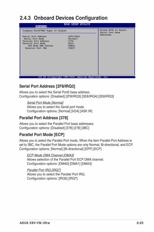
Serial Port Address [2F8/IRQ3]Allows you to select the Serial Port2 base address. Configuration options: [Disabled] [2F8/IRQ3] [3E8/IRQ4] [2E8/IRQ3]
Serial Port Mode [Normal]Allows you to select the Serial port mode. Configuration options: [Normal] [IrDA] [ASK IR]
Parallel Port Address [378]Allows you to select the Parallel Port base addresses. Configuration options: [Disabled] [378] [278] [3BC]
Parallel Port Mode [ECP]Allows you to select the Parallel Port mode. When the item Parallel Port Address is set to 3BC, the Parallel Port Mode options are only Normal, Bi-directional, and ECP. Configuration options: [Normal] [Bi-directional] [EPP] [ECP]
ECP Mode DMA Channel [DMA3]Allows selection of the Parallel Port ECP DMA channel. Configuration options: [DMA0] [DMA1] [DMA3]
Parallel Port IRQ [IRQ7]Allows you to select the Parallel Port IRQ. Configuration options: [IRQ5] [IRQ7]
2.4.3 Onboard Devices Configuration
Configure Win627EHF Super IO Chipset
Serial Port Address [2F8/IRQ3] Serial Port Mode [Normal]Parallel Port Address [378]Parallel Port Mode [ECP] ECP Mode DMA Channel [DMA3] Parallel Port IRQ [IRQ7]
v02.58 (C)Copyright 1985-2004, American Megatrends, Inc.
Allows BIOS to SelectSerial Port BaseAddresses.
2-24 Chapter 2: BIOS Information
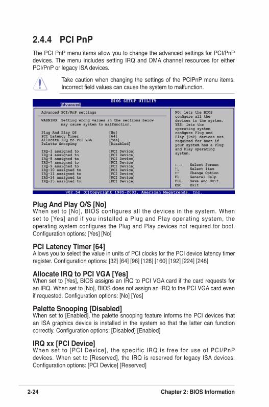
2.4.4 PCI PnPThe PCI PnP menu items allow you to change the advanced settings for PCI/PnP devices. The menu includes setting IRQ and DMA channel resources for either PCI/PnP or legacy ISA devices.
Take caution when changing the settings of the PCIPnP menu items. Incorrect field values can cause the system to malfunction.
NO: lets the BIOSconfigure all thedevices in the system.YES: lets the operating systemconfigure Plug andPlay (PnP) devices notrequired for boot ifyour system has a Plugand Play operatingsystem.
Advanced PCI/PnP settings
WARNING: Setting wrong values in the sections below may cause system to malfunction.
Plug And Play OS [No]PCI Latency Timer [64]Allocate IRQ to PCI VGA [Yes]Palette Snooping [Disabled]
IRQ-3 assigned to [PCI Device]IRQ-4 assigned to [PCI Device]IRQ-5 assigned to [PCI Device]IRQ-7 assigned to [PCI Device]IRQ-9 assigned to [PCI Device]IRQ-10 assigned to [PCI Device]IRQ-11 assigned to [PCI Device]IRQ-14 assigned to [PCI Device]IRQ-15 assigned to [PCI Device]
v02.54 (C)Copyright 1985-2003, American Megatrends, Inc.
←→ Select Screen↑↓ Select Item+- Change OptionF1 General HelpF10 Save and ExitESC Exit
Plug And Play O/S [No]When set to [No], BIOS configures all the devices in the system. When set to [Yes] and if you instal led a Plug and Play operating system, the operating system configures the Plug and Play devices not required for boot. Configuration options: [Yes] [No]
PCI Latency Timer [64]Allows you to select the value in units of PCI clocks for the PCI device latency timer register. Configuration options: [32] [64] [96] [128] [160] [192] [224] [248]
Allocate IRQ to PCI VGA [Yes]When set to [Yes], BIOS assigns an IRQ to PCI VGA card if the card requests for an IRQ. When set to [No], BIOS does not assign an IRQ to the PCI VGA card even if requested. Configuration options: [No] [Yes]
Palette Snooping [Disabled]When set to [Enabled], the palette snooping feature informs the PCI devices that an ISA graphics device is installed in the system so that the latter can function correctly. Configuration options: [Disabled] [Enabled]
IRQ xx [PCI Device]When set to [PCI Device], the specif ic IRQ is free for use of PCI/PnP devices. When set to [Reserved], the IRQ is reserved for legacy ISA devices. Configuration options: [PCI Device] [Reserved]
ASUS K8V-VM Ultra Motherboard 2-25
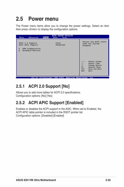
2.5 Power menuThe Power menu items allow you to change the power settings. Select an item then press <Enter> to display the configuration options.
2.5.1 ACPI 2.0 Support [No]Allows you to add more tables for ACPI 2.0 specifications. Configuration options: [No] [Yes]
2.5.2 ACPI APIC Support [Enabled]Enables or disables the ACPI support in the ASIC. When set to Enabled, the ACPI APIC table pointer is included in the RSDT pointer list. Configuration options: [Disabled] [Enabled]
ACPI 2.0 Support [Yes]ACPI APIC Support [Enabled]
APM Configuration Hardware Monitor
Select the ACPI stateused for SystemSuspend.
v02.54 (C)Copyright 1985-2003, American Megatrends, Inc.
←→ Select Screen↑↓ Select Item+- Change OptionF1 General HelpF10 Save and ExitESC Exit
2-26 Chapter 2: BIOS Information
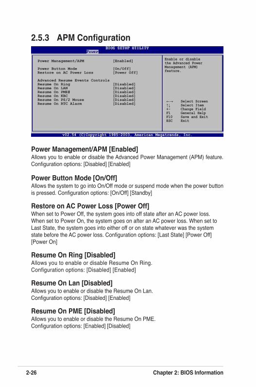
2.5.3 APM Configuration
Enable or disable the Advanced Power Management (APM) feature.
Power Management/APM [Enabled]Allows you to enable or disable the Advanced Power Management (APM) feature. Configuration options: [Disabled] [Enabled]
Power Button Mode [On/Off]Allows the system to go into On/Off mode or suspend mode when the power button is pressed. Configuration options: [On/Off] [Standby]
Restore on AC Power Loss [Power Off]When set to Power Off, the system goes into off state after an AC power loss. When set to Power On, the system goes on after an AC power loss. When set to Last State, the system goes into either off or on state whatever was the system state before the AC power loss. Configuration options: [Last State] [Power Off] [Power On]
Resume On Ring [Disabled]Allows you to enable or disable Resume On Ring. Configuration options: [Disabled] [Enabled]
Resume On Lan [Disabled]Allows you to enable or disable the Resume On Lan. Configuration options: [Disabled] [Enabled]
Resume On PME [Disabled]Allows you to enable or disable the Resume On PME. Configuration options: [Enabled] [Disabled]
v02.54 (C)Copyright 1985-2003, American Megatrends, Inc.
←→ Select Screen↑↓ Select Item+- Change FieldF1 General HelpF10 Save and ExitESC Exit
Power Management/APM [Enabled]
Power Button Mode [On/Off]Restore on AC Power Loss [Power Off]
Advanced Resume Events ControlsResume On Ring [Disabled]Resume On LAN [Disabled]Resume On PME# [Disabled]Resume On KBC [Disabled]Resume On PS/2 Mouse [Disabled]Resume On RTC Alarm [Disabled]
ASUS K8V-VM Ultra Motherboard 2-27
ResumeOn KBC [Disabled]Allows you to use specific keys on the keyboard to turn on the system. When set to [S5], the item Wake-up Key is enabled. This feature requires an ATX power supply that provides at least 1A on the +5VSB lead. Configuration options: [Disabled] [Enabled]
Resume On PS/2 Mouse [Disabled]When set to [Enabled], this parameter allows you to use the PS/2 mouse to resume the system. This feature requires an ATX power supply that provides at least 1A on the +5VSB lead. Configuration options: [Disabled] [Enabled]
Resume On RTC Alarm [Disabled]When set to [Enabled], this option allows you to use the RTC alarm to turn on the system. Configuration options: [Enabled] [Disabled]
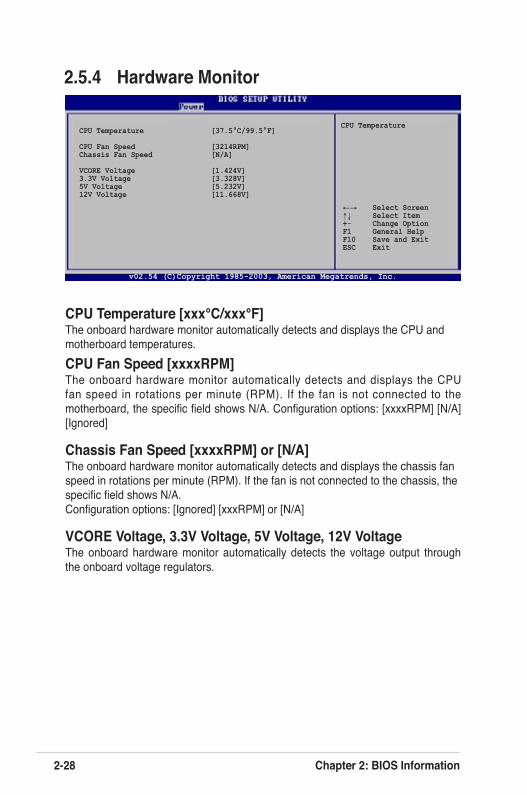
2-28 Chapter 2: BIOS Information
2.5.4 Hardware Monitor
CPU Temperature [xxx°C/xxx°F] The onboard hardware monitor automatically detects and displays the CPU and motherboard temperatures.CPU Fan Speed [xxxxRPM]The onboard hardware monitor automatically detects and displays the CPU fan speed in rotations per minute (RPM). If the fan is not connected to the motherboard, the specific field shows N/A. Configuration options: [xxxxRPM] [N/A] [Ignored]
Chassis Fan Speed [xxxxRPM] or [N/A]The onboard hardware monitor automatically detects and displays the chassis fan speed in rotations per minute (RPM). If the fan is not connected to the chassis, the specific field shows N/A. Configuration options: [Ignored] [xxxRPM] or [N/A]
VCORE Voltage, 3.3V Voltage, 5V Voltage, 12V VoltageThe onboard hardware monitor automatically detects the voltage output through the onboard voltage regulators.
CPU Temperature [37.5°C/99.5°F]
CPU Fan Speed [3214RPM]Chassis Fan Speed [N/A]
VCORE Voltage [1.424V]3.3V Voltage [3.328V]5V Voltage [5.232V]12V Voltage [11.668V]
CPU Temperature
v02.54 (C)Copyright 1985-2003, American Megatrends, Inc.
←→ Select Screen↑↓ Select Item+- Change OptionF1 General HelpF10 Save and ExitESC Exit
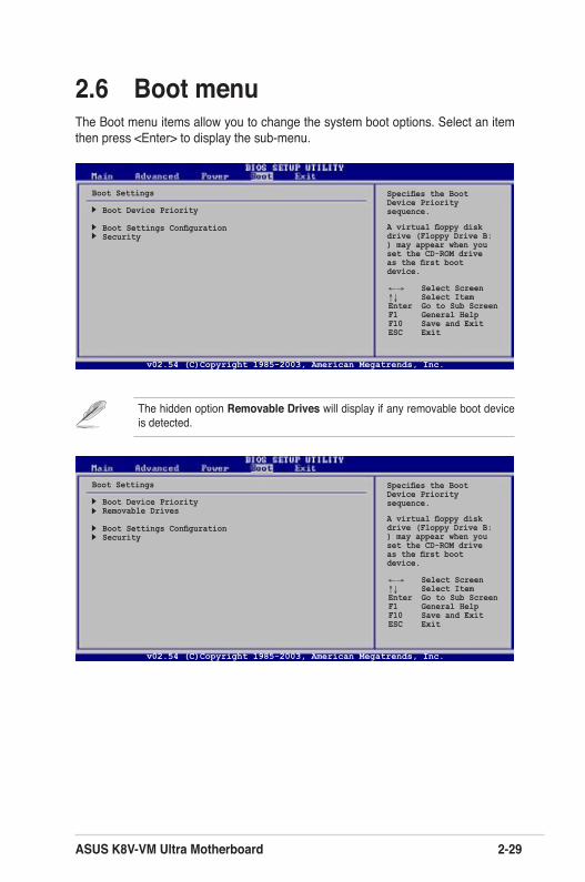
ASUS K8V-VM Ultra Motherboard 2-29
2.6 Boot menuThe Boot menu items allow you to change the system boot options. Select an item then press <Enter> to display the sub-menu.
Boot Settings
Boot Device Priority
Boot Settings ConfigurationSecurity
Specifies the Boot Device Priority sequence.
A virtual floppy disk drive (Floppy Drive B: ) may appear when you set the CD-ROM drive as the first boot device.
v02.54 (C)Copyright 1985-2003, American Megatrends, Inc.
←→ Select Screen↑↓ Select ItemEnter Go to Sub ScreenF1 General HelpF10 Save and ExitESC Exit
The hidden option Removable Drives will display if any removable boot device is detected.
Boot Settings
Boot Device PriorityRemovable Drives
Boot Settings ConfigurationSecurity
Specifies the Boot Device Priority sequence.
A virtual floppy disk drive (Floppy Drive B: ) may appear when you set the CD-ROM drive as the first boot device.
v02.54 (C)Copyright 1985-2003, American Megatrends, Inc.
←→ Select Screen↑↓ Select ItemEnter Go to Sub ScreenF1 General HelpF10 Save and ExitESC Exit
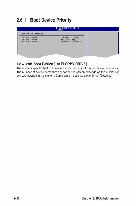
2-30 Chapter 2: BIOS Information
2.6.1 Boot Device Priority
1st ~ xxth Boot Device [1st FLOPPY DRIVE]These items specify the boot device priority sequence from the available devices. The number of device items that appear on the screen depends on the number of devices installed in the system. Configuration options: [xxxxx Drive] [Disabled]
Specifies the boot sequence from the available devices.
A device enclosed inparenthesis has been disabled in the corresponding type menu.
Boot Device Priority
1st Boot Device [1st FLOPPY DRIVE]2nd Boot Device [PM-ST340014A]3rd Boot Device [SM-ASUS DVD-E616P2]
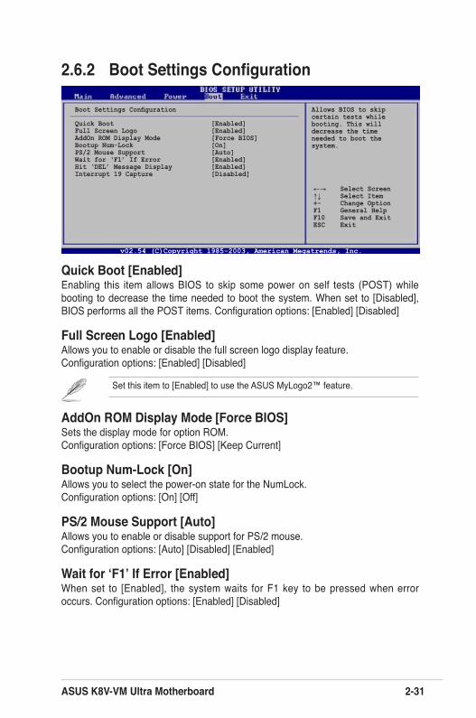
ASUS K8V-VM Ultra Motherboard 2-31
2.6.2 Boot Settings Configuration
Quick Boot [Enabled]Enabling this item allows BIOS to skip some power on self tests (POST) while booting to decrease the time needed to boot the system. When set to [Disabled], BIOS performs all the POST items. Configuration options: [Enabled] [Disabled]
Full Screen Logo [Enabled]Allows you to enable or disable the full screen logo display feature.Configuration options: [Enabled] [Disabled]
Set this item to [Enabled] to use the ASUS MyLogo2™ feature.
Boot Settings Configuration
Quick Boot [Enabled]Full Screen Logo [Enabled]AddOn ROM Display Mode [Force BIOS]Bootup Num-Lock [On]PS/2 Mouse Support [Auto]Wait for ‘F1’ If Error [Enabled]Hit ‘DEL’ Message Display [Enabled]Interrupt 19 Capture [Disabled]
Allows BIOS to skipcertain tests whilebooting. This willdecrease the timeneeded to boot thesystem.
AddOn ROM Display Mode [Force BIOS]Sets the display mode for option ROM. Configuration options: [Force BIOS] [Keep Current]
Bootup Num-Lock [On]Allows you to select the power-on state for the NumLock. Configuration options: [On] [Off]
PS/2 Mouse Support [Auto]Allows you to enable or disable support for PS/2 mouse. Configuration options: [Auto] [Disabled] [Enabled]
Wait for ‘F1’ If Error [Enabled]When set to [Enabled], the system waits for F1 key to be pressed when error occurs. Configuration options: [Enabled] [Disabled]
v02.54 (C)Copyright 1985-2003, American Megatrends, Inc.
←→ Select Screen↑↓ Select Item+- Change OptionF1 General HelpF10 Save and ExitESC Exit
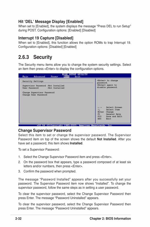
2-32 Chapter 2: BIOS Information
Change Supervisor PasswordSelect this item to set or change the supervisor password. The Supervisor Password item on top of the screen shows the default Not Installed. After you have set a password, this item shows Installed.
To set a Supervisor Password:
1. Select the Change Supervisor Password item and press <Enter>.2. On the password box that appears, type a password composed of at least six
letters and/or numbers, then press <Enter>.3. Confirm the password when prompted.
The message “Password Installed” appears after you successfully set your password. The Supervisor Password item now shows “Installed”. To change the supervisor password, follow the same steps as in setting a user password.
To clear the supervisor password, select the Change Supervisor Password then press Enter. The message “Password Uninstalled” appears.
To clear the supervisor password, select the Change Supervisor Password then press Enter. The message “Password Uninstalled” appears.
2.6.3 SecurityThe Security menu items allow you to change the system security settings. Select an item then press <Enter> to display the configuration options.
Security Settings
Supervisor Password :Not InstalledUser Password :Not Installed
Change Supervisor PasswordChange User Password
<Enter> to change password.<Enter> again to disable password.
Hit ‘DEL’ Message Display [Enabled]When set to [Enabled], the system displays the message “Press DEL to run Setup” during POST. Configuration options: [Enabled] [Disabled]
Interrupt 19 Capture [Disabled]When set to [Enabled], this function allows the option ROMs to trap Interrupt 19. Configuration options: [Disabled] [Enabled]
v02.54 (C)Copyright 1985-2003, American Megatrends, Inc.
←→ Select Screen↑↓ Select ItemEnter ChangeF1 General HelpF10 Save and ExitESC Exit
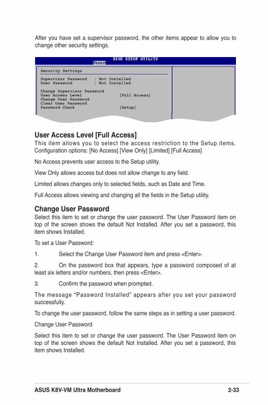
ASUS K8V-VM Ultra Motherboard 2-33
After you have set a supervisor password, the other items appear to allow you to change other security settings.
User Access Level [Full Access]This item allows you to select the access restriction to the Setup items. Configuration options: [No Access] [View Only] [Limited] [Full Access]
No Access prevents user access to the Setup utility.
View Only allows access but does not allow change to any field.
Limited allows changes only to selected fields, such as Date and Time.
Full Access allows viewing and changing all the fields in the Setup utility.
Change User PasswordSelect this item to set or change the user password. The User Password item on top of the screen shows the default Not Installed. After you set a password, this item shows Installed.
To set a User Password:
1. Select the Change User Password item and press <Enter>.
2. On the password box that appears, type a password composed of at least six letters and/or numbers, then press <Enter>.
3. Confirm the password when prompted.
The message “Password Installed” appears after you set your password successfully.
To change the user password, follow the same steps as in setting a user password.
Change User Password
Select this item to set or change the user password. The User Password item on top of the screen shows the default Not Installed. After you set a password, this item shows Installed.
Select Screen Select Item+- Change OptionF1 General HelpF10 Save and ExitESC Exit
Security Settings
Supervisor Password : Not InstalledUser Password : Not Installed
Change Supervisor PasswordUser Access Level [Full Access]Change User PasswordClear User PasswordPassword Check [Setup]
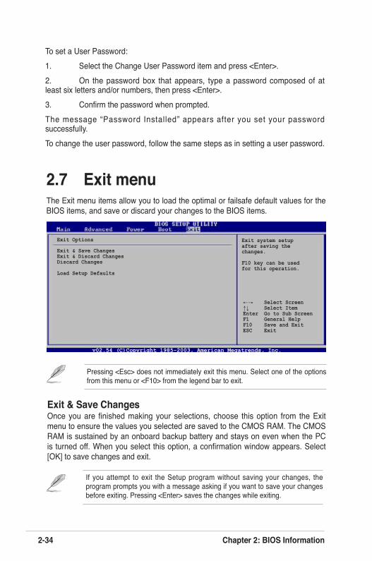
2-34 Chapter 2: BIOS Information
2.7 Exit menuThe Exit menu items allow you to load the optimal or failsafe default values for the BIOS items, and save or discard your changes to the BIOS items.
Pressing <Esc> does not immediately exit this menu. Select one of the options from this menu or <F10> from the legend bar to exit.
Exit Options
Exit & Save ChangesExit & Discard ChangesDiscard Changes
Load Setup Defaults
Exit system setup after saving the changes.
F10 key can be used for this operation.
v02.54 (C)Copyright 1985-2003, American Megatrends, Inc.
←→ Select Screen↑↓ Select ItemEnter Go to Sub ScreenF1 General HelpF10 Save and ExitESC Exit
Exit & Save ChangesOnce you are finished making your selections, choose this option from the Exit menu to ensure the values you selected are saved to the CMOS RAM. The CMOS RAM is sustained by an onboard backup battery and stays on even when the PC is turned off. When you select this option, a confirmation window appears. Select [OK] to save changes and exit.
If you attempt to exit the Setup program without saving your changes, the program prompts you with a message asking if you want to save your changes before exiting. Pressing <Enter> saves the changes while exiting.
To set a User Password:1. Select the Change User Password item and press <Enter>.2. On the password box that appears, type a password composed of at least six letters and/or numbers, then press <Enter>. 3. Confirm the password when prompted. The message “Password Installed” appears after you set your password successfully. To change the user password, follow the same steps as in setting a user password.
ASUS K8V-VM Ultra Motherboard 2-35
Exit & Discard ChangesSelect this option only if you do not want to save the changes that you made to the Setup program. If you made changes to fields other than system date, system time, and password, the BIOS asks for a confirmation before exiting.
Discard ChangesThis option allows you to discard the selections you made and restore the previously saved values. After selecting this option, a confirmation appears. Select [OK] to discard any changes and load the previously saved values.
Load Setup Defaults This option allows you to load the default values for each of the parameters on the Setup menus. When you select this option, or if you press <F5>, a confirmation window appears. Select [OK] to load the default values. Select Exit & Save Changes or make other changes before saving the values to the non-volatile RAM.
2-36 Chapter 2: BIOS Information
This chapter describes the contents of the support CD that comes with the motherboard package.
Chapter 3
Software Support
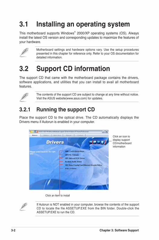
3-2 Chapter 3: Software Support
If Autorun is NOT enabled in your computer, browse the contents of the support CD to locate the file ASSETUP.EXE from the BIN folder. Double-click the ASSETUP.EXE to run the CD.
Click an item to install
3.1 Installing an operating systemThis motherboard supports Windows® 2000/XP operating systems (OS). Always install the latest OS version and corresponding updates to maximize the features of your hardware.
3.2 Support CD informationThe support CD that came with the motherboard package contains the drivers, software applications, and utilities that you can install to avail all motherboard features.
3.2.1 Running the support CDPlace the support CD to the optical drive. The CD automatically displays the Drivers menu if Autorun is enabled in your computer.
Motherboard settings and hardware options vary. Use the setup procedures presented in this chapter for reference only. Refer to your OS documentation for detailed information.
The contents of the support CD are subject to change at any time without notice. Visit the ASUS website(www.asus.com) for updates.
Click an icon to display support CD/motherboard information
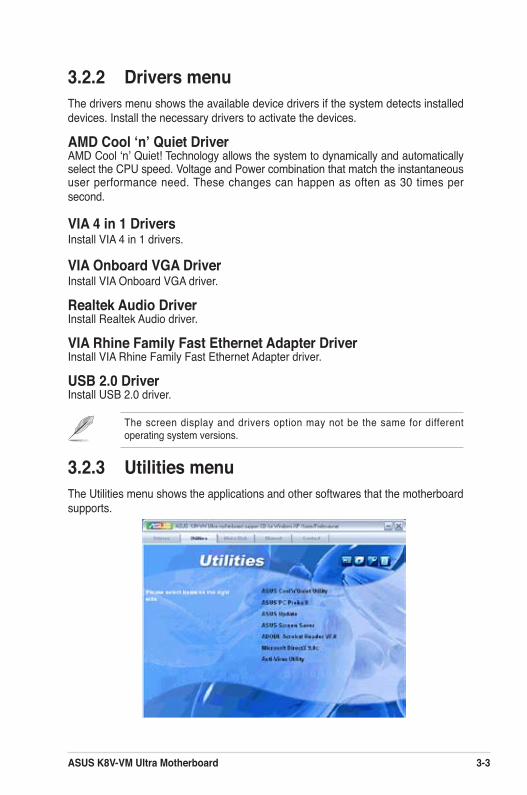
ASUS K8V-VM Ultra Motherboard 3-3
3.2.2 Drivers menuThe drivers menu shows the available device drivers if the system detects installed devices. Install the necessary drivers to activate the devices.
AMD Cool ‘n’ Quiet DriverAMD Cool ‘n’ Quiet! Technology allows the system to dynamically and automatically select the CPU speed. Voltage and Power combination that match the instantaneous user performance need. These changes can happen as often as 30 times per second.
VIA 4 in 1 DriversInstall VIA 4 in 1 drivers.
VIA Onboard VGA DriverInstall VIA Onboard VGA driver.
Realtek Audio DriverInstall Realtek Audio driver.
VIA Rhine Family Fast Ethernet Adapter DriverInstall VIA Rhine Family Fast Ethernet Adapter driver.
USB 2.0 DriverInstall USB 2.0 driver.
The screen display and drivers option may not be the same for different operating system versions.
3.2.3 Utilities menuThe Utilities menu shows the applications and other softwares that the motherboard supports.
3-4 Chapter 3: Software Support
ASUS Cool ‘n’ Quiet UtilityInstalls the ASUS Cool ‘n’ Quiet software.
ASUS PC Probe IIThis smart utility monitors the fan speed, CPU temperature, and system voltages, and alerts you of any detected problems. This utility helps you keep your computer in healthy operating condition.
ASUS Update The ASUS Update utility allows you to update the motherboard BIOS in Windows® environment. This utility requires an Internet connection either through a network or an Internet Service Provider (ISP).
ASUS Screen SaverBring life to your idle screen by installing the ASUS screen saver.
ADOBE Acrobat Reader V7.0The Adobe Acrobat® Reader V7.0 is for opening, viewing, and printing documents in Portable Document Format (PDF).
Microsoft DirectX 9.0c DirverThe Microsoft DirectX® 9.0c is a multimedia technology that enhances computer graphics and sounds. DirectX® improves the multimedia features of your computer so you can enjoy watching TV and movies, capturing videos, or playing games in your computer.
Anti-virus Utility The anti-virus application scans, identifies, and removes computer viruses. View the online help for detailed information.
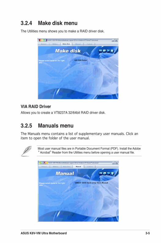
ASUS K8V-VM Ultra Motherboard 3-5
3.2.4 Make disk menuThe Utilities menu shows you to make a RAID driver disk.
VIA RAID DriverAllows you to create a VT8237A 32/64bit RAID driver disk.
3.2.5 Manuals menuThe Manuals menu contains a list of supplementary user manuals. Click an item to open the folder of the user manual.
Most user manual files are in Portable Document Format (PDF). Install the Adobe® Acrobat® Reader from the Utilities menu before opening a user manual file.
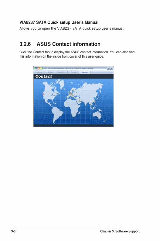
3-6 Chapter 3: Software Support
VIA8237 SATA Quick setup User’s ManualAllows you to open the VIA8237 SATA quick setup userʼs manual.
3.2.6 ASUS Contact informationClick the Contact tab to display the ASUS contact information. You can also find this information on the inside front cover of this user guide.