Embed Size (px)
Citation preview
K8V series
Closed-LoopSwash Plate Type Axial Piston Pump

1
I. Applications / Product Usage 2II. Safety Precautions 3III. Handling Precautions 1. Operating Fluid and Temperature Range 4 1) Operating Fluid 2) Viscosity and Temperature Range 2. Filtration and Contamination Control 1) Filtration of Working Oil 2) Suggested Acceptable Cleanliness Level 3. Drive Shaft Coupling 5 4. Oil Filling and Air Bleeding 1) Pump Case Filling 2) Air Bleeding 3) Long Term Storage 5. Drain Piping 6 1) Installation of Drain Line 2) Size of Drain Hose • Drain Pipe 7 6. Shaft Loading and Bearing LifeIV. Conversion Factors, Formula and Definition 8
• K8V Series Closed-Loop Variable Displacement Type Axial Piston PumpSpecifications, General Descriptions, and Features 10 1. Ordering Code 1-1. Pump Options 11 1-2. Regulator Options 12 2. Technical Information 2-1. Specifications 13 • Relief Valve 14 • Pressure Cut-off • Charge Pump 15 2-2. Functional Description of Regulator • Electric Proportional Control 17 • Hydraulic Pilot Displacement Control 18 • Mechanical Stroke Limiter 19 • Stroking Speed Control Orifice 3. Dimensions 3-1. Installation Dimensions • K8V90 20 • K8V90 Port Details 21 • K8V90 Through Drive Options 22 • K8V125 25 • K8V125 Port Details 27 • K8V125 Through Drive Options 28 3-2. Installation of Auxiliary Pumps 31 K8V Series Inquiry Form 32
CONTENTS
2
K8V series
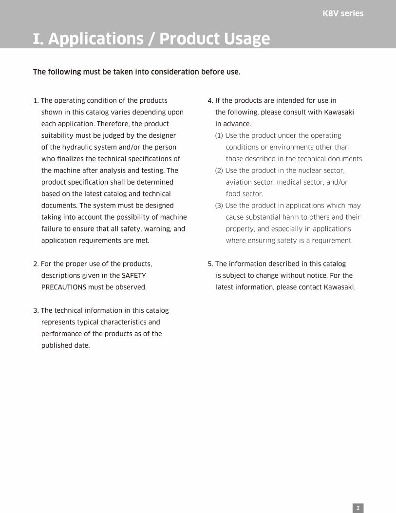
I. Applications / Product Usage
The following must be taken into consideration before use.
1. The operating condition of the products
shown in this catalog varies depending upon
each application. Therefore, the product
suitability must be judged by the designer
of the hydraulic system and/or the person
who finalizes the technical specifications of
the machine after analysis and testing. The
product specification shall be determined
based on the latest catalog and technical
documents. The system must be designed
taking into account the possibility of machine
failure to ensure that all safety, warning, and
application requirements are met.
2. For the proper use of the products,
descriptions given in the SAFETY
PRECAUTIONS must be observed.
3. The technical information in this catalog
represents typical characteristics and
performance of the products as of the
published date.
4. If the products are intended for use in
the following, please consult with Kawasaki
in advance.
(1) Use the product under the operating
conditions or environments other than
those described in the technical documents.
(2) Use the product in the nuclear sector,
aviation sector, medical sector, and/or
food sector.
(3) Use the product in applications which may
cause substantial harm to others and their
property, and especially in applications
where ensuring safety is a requirement.
5. The information described in this catalog
is subject to change without notice. For the
latest information, please contact Kawasaki.
3
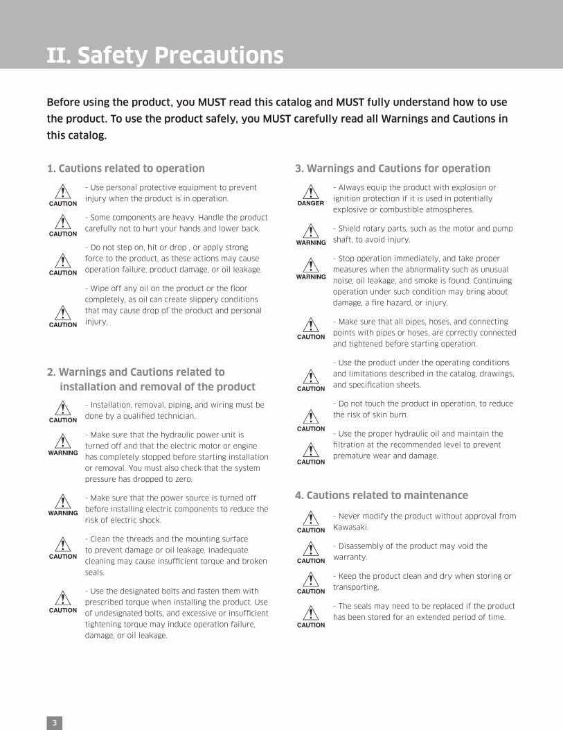
II. Safety Precautions
Before using the product, you MUST read this catalog and MUST fully understand how to use
the product. To use the product safely, you MUST carefully read all Warnings and Cautions in
this catalog.
1. Cautions related to operation
2. Warnings and Cautions related to installation and removal of the product
3. Warnings and Cautions for operation
4. Cautions related to maintenance
- Use personal protective equipment to prevent
injury when the product is in operation.
- Some components are heavy. Handle the product
carefully not to hurt your hands and lower back.
- Do not step on, hit or drop , or apply strong
force to the product, as these actions may cause
operation failure, product damage, or oil leakage.
- Wipe off any oil on the product or the floor
completely, as oil can create slippery conditions
that may cause drop of the product and personal
injury.
- Installation, removal, piping, and wiring must be
done by a qualified technician.
- Make sure that the hydraulic power unit is
turned off and that the electric motor or engine
has completely stopped before starting installation
or removal. You must also check that the system
pressure has dropped to zero.
- Make sure that the power source is turned off
before installing electric components to reduce the
risk of electric shock.
- Clean the threads and the mounting surface
to prevent damage or oil leakage. Inadequate
cleaning may cause insufficient torque and broken
seals.
- Use the designated bolts and fasten them with
prescribed torque when installing the product. Use
of undesignated bolts, and excessive or insufficient
tightening torque may induce operation failure,
damage, or oil leakage.
- Always equip the product with explosion or
ignition protection if it is used in potentially
explosive or combustible atmospheres.
- Shield rotary parts, such as the motor and pump
shaft, to avoid injury.
- Stop operation immediately, and take proper
measures when the abnormality such as unusual
noise, oil leakage, and smoke is found. Continuing
operation under such condition may bring about
damage, a fire hazard, or injury.
- Make sure that all pipes, hoses, and connecting
points with pipes or hoses, are correctly connected
and tightened before starting operation.
- Use the product under the operating conditions
and limitations described in the catalog, drawings,
and specification sheets.
- Do not touch the product in operation, to reduce
the risk of skin burn.
- Use the proper hydraulic oil and maintain the
filtration at the recommended level to prevent
premature wear and damage.
- Never modify the product without approval from
Kawasaki.
- Disassembly of the product may void the
warranty.
- Keep the product clean and dry when storing or
transporting.
- The seals may need to be replaced if the product
has been stored for an extended period of time.

Viscosity [mm2/s(cSt)]
Fluid Temperature[°F (°C)]
Suitable range forNormal operation Allowable range
10 ~ 200 10 ~ 1,000
-4 ~ +203 (-20 ~ +95)
1000
600400
200
1008060
40
20
10-4(−20) 68(20) 104(40) 140(60) 176(80) 212(100) 32(0)
Recommend
Suitable range for Normal operation
�uid temperature ºF(ºC)
kin
emat
ic v
isco
sity
(cS
t)
allowable temperature range
4
K8V series
III. Handling Precautions
1. Operating Fluid and Temperature Range
1) Operating Fluid
Values shown in this catalog are based upon using
mineral based anti-wear hydraulic fluid. To ensure
optimal performance use of mineral based anti-wear
hydraulic fluid is recommended.
2) Viscosity and Temperature Range
To minimize both oil and seal deterioration, a
maximum operating temperature of 140ºF (60ºC)
should be considered. Additionally it must be noted
that when operating at low temperatures 59~68ºF
(15~20ºC) some delay in response of the regulator
may occur. At such low temperatures it is suggested
that a warm up cycle is introduced until an operating
temperature of 68ºF (20ºC) is achieved.
2. Filtration and Contamination Control
1) Filtration
The most important means to prevent premature
damage to the pump and associated equipment and
to extend its working life, is to ensure that hydraulic
fluid contamination control of the system is working
effectively.
This begins by ensuring that at the time of installation
that all piping, tanks etc. are rigorously cleaned in a
sanitary way. Flushing should be provided using an
off line filtration system and after flushing the filter
elements should be replaced.
2) Suggested Acceptable Cleanliness Level
The relationship between contamination level and
pump life is very difficult to predict as it depends on
the type and nature of the contaminant present in the
system. Sand or Silica in particular, due to its abrasive
nature, does significantly reduce the expected life of
a pump. Based on the precondition that there is no
significant presence of Silica type substances then a
minimum Cleanliness level of -/18/15 ISO 4406 or
SAE AS 4059E Table 1 Class 9 (NAS 1638 Class 9).
5
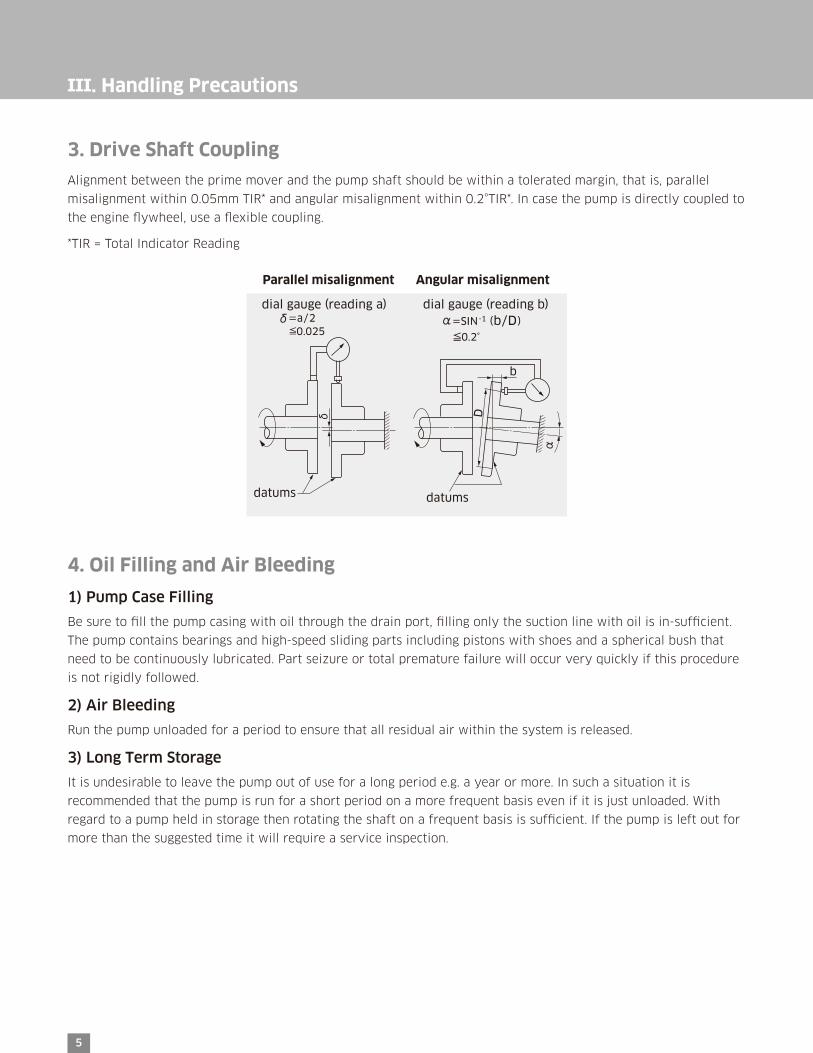
3. Drive Shaft Coupling
Alignment between the prime mover and the pump shaft should be within a tolerated margin, that is, parallel
misalignment within 0.05mm TIR* and angular misalignment within 0.2°TIR*. In case the pump is directly coupled to
the engine flywheel, use a flexible coupling.
*TIR = Total Indicator Reading
4. Oil Filling and Air Bleeding
1) Pump Case Filling
Be sure to fill the pump casing with oil through the drain port, filling only the suction line with oil is in-sufficient.
The pump contains bearings and high-speed sliding parts including pistons with shoes and a spherical bush that
need to be continuously lubricated. Part seizure or total premature failure will occur very quickly if this procedure
is not rigidly followed.
2) Air Bleeding
Run the pump unloaded for a period to ensure that all residual air within the system is released.
3) Long Term Storage
It is undesirable to leave the pump out of use for a long period e.g. a year or more. In such a situation it is
recommended that the pump is run for a short period on a more frequent basis even if it is just unloaded. With
regard to a pump held in storage then rotating the shaft on a frequent basis is sufficient. If the pump is left out for
more than the suggested time it will require a service inspection.
III. Handling Precautions
dial gauge (reading a) δ =a/2 ≦0.025
dial gauge (reading b) α =SIN-1 (b/D)
≦0.2°
datumsdatums
δ
α
D
b
Parallel misalignment Angular misalignment
P dr
0.1sec
87psi (6 bar)(peak)
29psi (2 bar)(normal)
Fluid level
20
0m
m
min
imum
dep
thM
ust
be
hig
her
than
top o
f pum
p c
ase.
7.8
” (2
00
mm
) m
inim
um
dep
th
7.8
” (2
00
mm
) m
inim
um
dep
th
Fluid level
wit
hin
40
” (1
m)
wit
hin
40
” (1
m)
6
K8V series
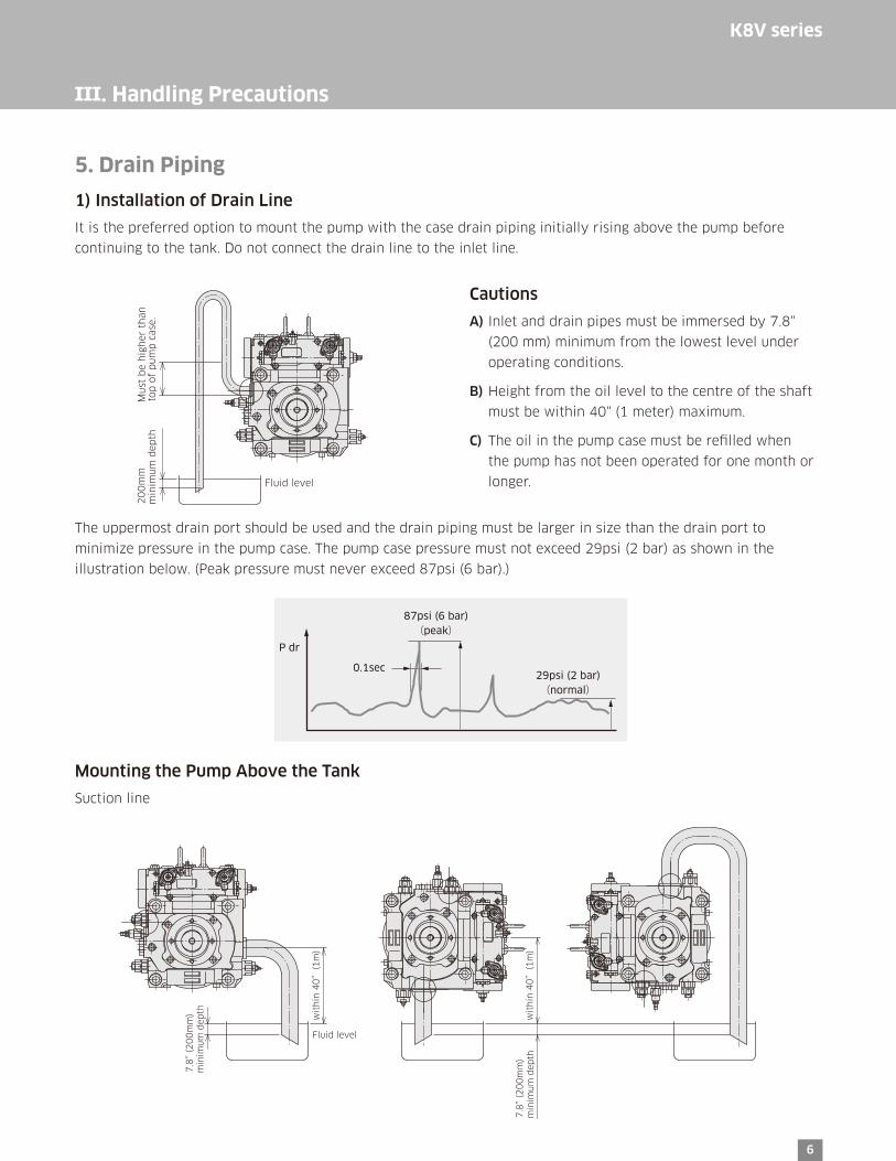
5. Drain Piping
1) Installation of Drain Line
It is the preferred option to mount the pump with the case drain piping initially rising above the pump before
continuing to the tank. Do not connect the drain line to the inlet line.
The uppermost drain port should be used and the drain piping must be larger in size than the drain port to
minimize pressure in the pump case. The pump case pressure must not exceed 29psi (2 bar) as shown in the
illustration below. (Peak pressure must never exceed 87psi (6 bar).)
Cautions
A) Inlet and drain pipes must be immersed by 7.8"
(200 mm) minimum from the lowest level under
operating conditions.
B) Height from the oil level to the centre of the shaft
must be within 40" (1 meter) maximum.
C) The oil in the pump case must be refilled when
the pump has not been operated for one month or
longer.
III. Handling Precautions
Mounting the Pump Above the Tank
Suction line

7
2) Size of Drain Hose or Drain Pipe
The internal bore size of the drain hose or drain pipe must be larger than that of the drain port. Arrange the drain
line as short as possible.
6. Shaft Loading and Bearing Life
Although K8V pumps are equipped with bearings that can accept some external radial forces, exertion of external
radial loads will affect bearing life. Depending on the load magnitude, the load position, and the load orientation,
bearing life may be influenced and reduced.
Consult with Kawasaki for further details.
III. Handling Precautions

Formula Note
Displacement 1 cm3 = 0.061 in3
Pressure 1 MPa = 145 psi
Flow 1 L/min = 0.264 gpm US gallon
Torque 1 Nm = 0.74 lb ft
Power 1 kW = 1.341 hp
Weight 1 kg = 2.205 lbs
8
K8V series
• Conversion Factors
• Formula
• Definition
IV. Conversion Factors, Formula and Definition
q = Pump displacement / rev. cm3 (in3)
L = Input power kW (hp)
N = Speed min-1 (rpm)
Nmax = Maximum speed at maximum displacement min-1 (rpm)
ΔP = Phigh – Plow (Differential pressure) MPa (psi)
Phigh = High pressure MPa (psi)
Plow = Low pressure MPa (psi)
Prated = Rated pressure MPa (psi)
Ppeak = Peak pressure MPa (psi)
PC = charge pressure MPa (psi)
T = Input torque Nm (lbf-ft)
Tmax = Maximum input torque Nm (lbf-ft)
nv = Pump volumetric efficiency
nm = Pump mechanical efficiency
nt = Pump total efficiency
Metric system Imperial system
Output flow Q = q x N x nv / 1000 L/min Q = q x N x nv / 231 gal/min
Input torque T = q x ΔP / 2π / nm Nm T = q x ΔP / 24π / nm lbf-ft
Input power L = T x N / 9550 = Q x ΔP / 60 / nt kW L = T x N / 5252 = Q x ΔP / 1714 / nt hp

. . . . . . . . . . . . . . . . . . . . . . . . . . . . . . . . . . . . . . . . . . . . . . . . . . . . . . . . . . . . . . . . . . . . . . . . . . . . . . . . . . . . . . . . . . . . . . . . . . . . . . . . . . . . . . . . . . . . . . . . . . . . . . . . . . . . . . . . . . . . . . . . . . . . . . . . . . . . . . . . . . . . . . . .
. . . . . . . . . . . . . . . . . . . . . . . . . . . . . . . . . . . . . . . . . . . . . . . . . . . . . . . . . . . . . . . . . . . . . . . . . . . . . . . . . . . . . . . . . . . . . . . . . . . . . . . . . . . . . . . . . . . . . . . . . . . . . . . . . . . . . . . . . . . . . . . . . . . . . . . . . . . . . . . . . . . . . . . .
. . . . . . . . . . . . . . . . . . . . . . . . . . . . . . . . . . . . . . . . . . . . . . . . . . . . . . . . . . . . . . . . . . . . . . . . . . . . . . . . . . . . . . . . . . . . . . . . . . . . . . . . . . . . . . . . . . . . . . . . . . . . . . . . . . . . . . . . . . . . . . . . . . . . . . . . . . . . . . . . . . . . . . . .
. . . . . . . . . . . . . . . . . . . . . . . . . . . . . . . . . . . . . . . . . . . . . . . . . . . . . . . . . . . . . . . . . . . . . . . . . . . . . . . . . . . . . . . . . . . . . . . . . . . . . . . . . . . . . . . . . . . . . . . . . . . . . . . . . . . . . . . . . . . . . . . . . . . . . . . . . . . . . . . . . . . . . . . .
. . . . . . . . . . . . . . . . . . . . . . . . . . . . . . . . . . . . . . . . . . . . . . . . . . . . . . . . . . . . . . . . . . . . . . . . . . . . . . . . . . . . . . . . . . . . . . . . . . . . . . . . . . . . . . . . . . . . . . . . . . . . . . . . . . . . . . . . . . . . . . . . . . . . . . . . . . . . . . . . . . . . . . . .
. . . . . . . . . . . . . . . . . . . . . . . . . . . . . . . . . . . . . . . . . . . . . . . . . . . . . . . . . . . . . . . . . . . . . . . . . . . . . . . . . . . . . . . . . . . . . . . . . . . . . . . . . . . . . . . . . . . . . . . . . . . . . . . . . . . . . . . . . . . . . . . . . . . . . . . . . . . . . . . . . . . . . . . .
. . . . . . . . . . . . . . . . . . . . . . . . . . . . . . . . . . . . . . . . . . . . . . . . . . . . . . . . . . . . . . . . . . . . . . . . . . . . . . . . . . . . . . . . . . . . . . . . . . . . . . . . . . . . . . . . . . . . . . . . . . . . . . . . . . . . . . . . . . . . . . . . . . . . . . . . . . . . . . . . . . . . . . . .
. . . . . . . . . . . . . . . . . . . . . . . . . . . . . . . . . . . . . . . . . . . . . . . . . . . . . . . . . . . . . . . . . . . . . . . . . . . . . . . . . . . . . . . . . . . . . . . . . . . . . . . . . . . . . . . . . . . . . . . . . . . . . . . . . . . . . . . . . . . . . . . . . . . . . . . . . . . . . . . . . . . . . . . .
. . . . . . . . . . . . . . . . . . . . . . . . . . . . . . . . . . . . . . . . . . . . . . . . . . . . . . . . . . . . . . . . . . . . . . . . . . . . . . . . . . . . . . . . . . . . . . . . . . . . . . . . . . . . . . . . . . . . . . . . . . . . . . . . . . . . . . . . . . . . . . . . . . . . . . . . . . . . . . . . . . . . . . . .
. . . . . . . . . . . . . . . . . . . . . . . . . . . . . . . . . . . . . . . . . . . . . . . . . . . . . . . . . . . . . . . . . . . . . . . . . . . . . . . . . . . . . . . . . . . . . . . . . . . . . . . . . . . . . . . . . . . . . . . . . . . . . . . . . . . . . . . . . . . . . . . . . . . . . . . . . . . . . . . . . . . . . . . .
. . . . . . . . . . . . . . . . . . . . . . . . . . . . . . . . . . . . . . . . . . . . . . . . . . . . . . . . . . . . . . . . . . . . . . . . . . . . . . . . . . . . . . . . . . . . . . . . . . . . . . . . . . . . . . . . . . . . . . . . . . . . . . . . . . . . . . . . . . . . . . . . . . . . . . . . . . . . . . . . . . . . . . . .
. . . . . . . . . . . . . . . . . . . . . . . . . . . . . . . . . . . . . . . . . . . . . . . . . . . . . . . . . . . . . . . . . . . . . . . . . . . . . . . . . . . . . . . . . . . . . . . . . . . . . . . . . . . . . . . . . . . . . . . . . . . . . . . . . . . . . . . . . . . . . . . . . . . . . . . . . . . . . . . . . . . . . . . .
. . . . . . . . . . . . . . . . . . . . . . . . . . . . . . . . . . . . . . . . . . . . . . . . . . . . . . . . . . . . . . . . . . . . . . . . . . . . . . . . . . . . . . . . . . . . . . . . . . . . . . . . . . . . . . . . . . . . . . . . . . . . . . . . . . . . . . . . . . . . . . . . . . . . . . . . . . . . . . . . . . . . . . . .
. . . . . . . . . . . . . . . . . . . . . . . . . . . . . . . . . . . . . . . . . . . . . . . . . . . . . . . . . . . . . . . . . . . . . . . . . . . . . . . . . . . . . . . . . . . . . . . . . . . . . . . . . . . . . . . . . . . . . . . . . . . . . . . . . . . . . . . . . . . . . . . . . . . . . . . . . . . . . . . . . . . . . . . .
. . . . . . . . . . . . . . . . . . . . . . . . . . . . . . . . . . . . . . . . . . . . . . . . . . . . . . . . . . . . . . . . . . . . . . . . . . . . . . . . . . . . . . . . . . . . . . . . . . . . . . . . . . . . . . . . . . . . . . . . . . . . . . . . . . . . . . . . . . . . . . . . . . . . . . . . . . . . . . . . . . . . . . . .
. . . . . . . . . . . . . . . . . . . . . . . . . . . . . . . . . . . . . . . . . . . . . . . . . . . . . . . . . . . . . . . . . . . . . . . . . . . . . . . . . . . . . . . . . . . . . . . . . . . . . . . . . . . . . . . . . . . . . . . . . . . . . . . . . . . . . . . . . . . . . . . . . . . . . . . . . . . . . . . . . . . . . . . .
. . . . . . . . . . . . . . . . . . . . . . . . . . . . . . . . . . . . . . . . . . . . . . . . . . . . . . . . . . . . . . . . . . . . . . . . . . . . . . . . . . . . . . . . . . . . . . . . . . . . . . . . . . . . . . . . . . . . . . . . . . . . . . . . . . . . . . . . . . . . . . . . . . . . . . . . . . . . . . . . . . . . . . . .
. . . . . . . . . . . . . . . . . . . . . . . . . . . . . . . . . . . . . . . . . . . . . . . . . . . . . . . . . . . . . . . . . . . . . . . . . . . . . . . . . . . . . . . . . . . . . . . . . . . . . . . . . . . . . . . . . . . . . . . . . . . . . . . . . . . . . . . . . . . . . . . . . . . . . . . . . . . . . . . . . . . . . . . .
. . . . . . . . . . . . . . . . . . . . . . . . . . . . . . . . . . . . . . . . . . . . . . . . . . . . . . . . . . . . . . . . . . . . . . . . . . . . . . . . . . . . . . . . . . . . . . . . . . . . . . . . . . . . . . . . . . . . . . . . . . . . . . . . . . . . . . . . . . . . . . . . . . . . . . . . . . . . . . . . . . . . . . . .
. . . . . . . . . . . . . . . . . . . . . . . . . . . . . . . . . . . . . . . . . . . . . . . . . . . . . . . . . . . . . . . . . . . . . . . . . . . . . . . . . . . . . . . . . . . . . . . . . . . . . . . . . . . . . . . . . . . . . . . . . . . . . . . . . . . . . . . . . . . . . . . . . . . . . . . . . . . . . . . . . . . . . . . .
. . . . . . . . . . . . . . . . . . . . . . . . . . . . . . . . . . . . . . . . . . . . . . . . . . . . . . . . . . . . . . . . . . . . . . . . . . . . . . . . . . . . . . . . . . . . . . . . . . . . . . . . . . . . . . . . . . . . . . . . . . . . . . . . . . . . . . . . . . . . . . . . . . . . . . . . . . . . . . . . . . . . . . . .
. . . . . . . . . . . . . . . . . . . . . . . . . . . . . . . . . . . . . . . . . . . . . . . . . . . . . . . . . . . . . . . . . . . . . . . . . . . . . . . . . . . . . . . . . . . . . . . . . . . . . . . . . . . . . . . . . . . . . . . . . . . . . . . . . . . . . . . . . . . . . . . . . . . . . . . . . . . . . . . . . . . . . . . .
. . . . . . . . . . . . . . . . . . . . . . . . . . . . . . . . . . . . . . . . . . . . . . . . . . . . . . . . . . . . . . . . . . . . . . . . . . . . . . . . . . . . . . . . . . . . . . . . . . . . . . . . . . . . . . . . . . . . . . . . . . . . . . . . . . . . . . . . . . . . . . . . . . . . . . . . . . . . . . . . . . . . . . . .
. . . . . . . . . . . . . . . . . . . . . . . . . . . . . . . . . . . . . . . . . . . . . . . . . . . . . . . . . . . . . . . . . . . . . . . . . . . . . . . . . . . . . . . . . . . . . . . . . . . . . . . . . . . . . . . . . . . . . . . . . . . . . . . . . . . . . . . . . . . . . . . . . . . . . . . . . . . . . . . . . . . . . . . .
. . . . . . . . . . . . . . . . . . . . . . . . . . . . . . . . . . . . . . . . . . . . . . . . . . . . . . . . . . . . . . . . . . . . . . . . . . . . . . . . . . . . . . . . . . . . . . . . . . . . . . . . . . . . . . . . . . . . . . . . . . . . . . . . . . . . . . . . . . . . . . . . . . . . . . . . . . . . . . . . . . . . . . . .
. . . . . . . . . . . . . . . . . . . . . . . . . . . . . . . . . . . . . . . . . . . . . . . . . . . . . . . . . . . . . . . . . . . . . . . . . . . . . . . . . . . . . . . . . . . . . . . . . . . . . . . . . . . . . . . . . . . . . . . . . . . . . . . . . . . . . . . . . . . . . . . . . . . . . . . . . . . . . . . . . . . . . . . .
. . . . . . . . . . . . . . . . . . . . . . . . . . . . . . . . . . . . . . . . . . . . . . . . . . . . . . . . . . . . . . . . . . . . . . . . . . . . . . . . . . . . . . . . . . . . . . . . . . . . . . . . . . . . . . . . . . . . . . . . . . . . . . . . . . . . . . . . . . . . . . . . . . . . . . . . . . . . . . . . . . . . . . . .
. . . . . . . . . . . . . . . . . . . . . . . . . . . . . . . . . . . . . . . . . . . . . . . . . . . . . . . . . . . . . . . . . . . . . . . . . . . . . . . . . . . . . . . . . . . . . . . . . . . . . . . . . . . . . . . . . . . . . . . . . . . . . . . . . . . . . . . . . . . . . . . . . . . . . . . . . . . . . . . . . . . . . . . .
MEMO
9

10
K8V series
Closed-Loop Variable Displacement Type Axial Piston Pump
K8V Series
• General Descriptions
The K8V series are variable displacement axial piston
pumps for closed loop systems, with superior overall
efficiency, stability, and control characteristics.
The K8V pumps are suitable for a wide range of
applications , including industrial vehicles such as
construction machinery, agricultural equipment
with hydrostatic drive systems, and other closed
loop applications. Also, this pump can be used in
combination with M7V series motors for high pressure
closed loop applications.
The K8V series with a range in pump size from 71cc &
125cc displacement and are equipped with electric or
hydraulic pilot displacement control. The K8V series
pumps, having the integrated components required for
a closed system, such as a charge pump, high and low
pressure relief valves, and a cut-off valve, enable a
compact closed loop system.
• Specifications
Size: 71*, 90, 125
Rated Pressure: 5800 psi (400 bar)
Peak Pressure: 6525 psi (450 bar)
• Features
• Swash plate type, variable displacement axial piston
pump for closed-loop system
• High overall efficiency
• Suitable for wide range of applications
• Precise flow control
• High stability
• Excellent reliability
• Various integrated valves
• Bypass function for emergency towing
(*) means under development

1. K8V Series PumpK8V Series, Variable Displacement, Axial Piston, Closed Loop Pump
2. Size
90 125
Pump Size cm3 ● ●
6. Through Drive
90 125
A1 SAE A, 2 bolt, Through Drive (9T, 16/32 DP) ● ● B1 SAE B, 2 bolt, Through Drive (13T, 16/32 DP) ● ● B2 SAE BB, 2 bolt, Through Drive (15T, 16/32 DP) ● ● C1 SAE C, 2/4 bolt, Through Drive (14T, 12/24 DP) ● ● C2 SAE CC, 2/4 bolt, Through Drive (17T, 12/24 DP) ● ● D1 SAE D, 2/4 bolt, Through Drive (13T, 8/16 DP) ● ● X Without Through Drive ● ●
9. Stroking Speed Control Ori�ce
90 125
A Φ0.8mm ― ● B Φ1.0mm ● ● C Φ1.2mm ● ● D Φ1.4mm ● ― X Without Ori�ce Available Only with Code X of Pressure Cut-off Valve [16] ● ●
8. Charge Pump
90 125
A 20 cm3 ● ― B 28 cm3 ― ● X Without Charge Pump ● ●
7. Thread Type (Suction/Delivery)
Type of Threaded Port Thread Type for Flange Port 90 125
A UNF Metric ● ● B Metric Metric ○ ○ C UNF UNF ● ●
4. Direction of rotation
90 125
R Clockwise ● ● L Counterclockwise ● ○
5. Mounting Flange and Shaft
90 125
D1 SAE D Mount & SAE D Shaft (13T, 8/16 DP) ● ● D2 SAE D Mount & SAE F Shaft (15T, 8/16 DP) ― ●
10. Mechanical Stroke Limiter
90 125
A With Mechanical Stroke Limiter ○ ○ X Without Mechanical Stroke Limiter ● ●
3. Model Code
90 125
A Series A ● ●
K8V 125 A R D1 A1 A B B X X X X - P1 D C B - 01Model Code1 2 3 5 6 7 8 9 10 12 13 14 15 16 17 18114
● : Available ○ : Under development ― : Not available
Please fill the Inquiry Form on page 32 and 33 in order to specify the requirement.
11
1 Ordering Code
1-1 Pump Options
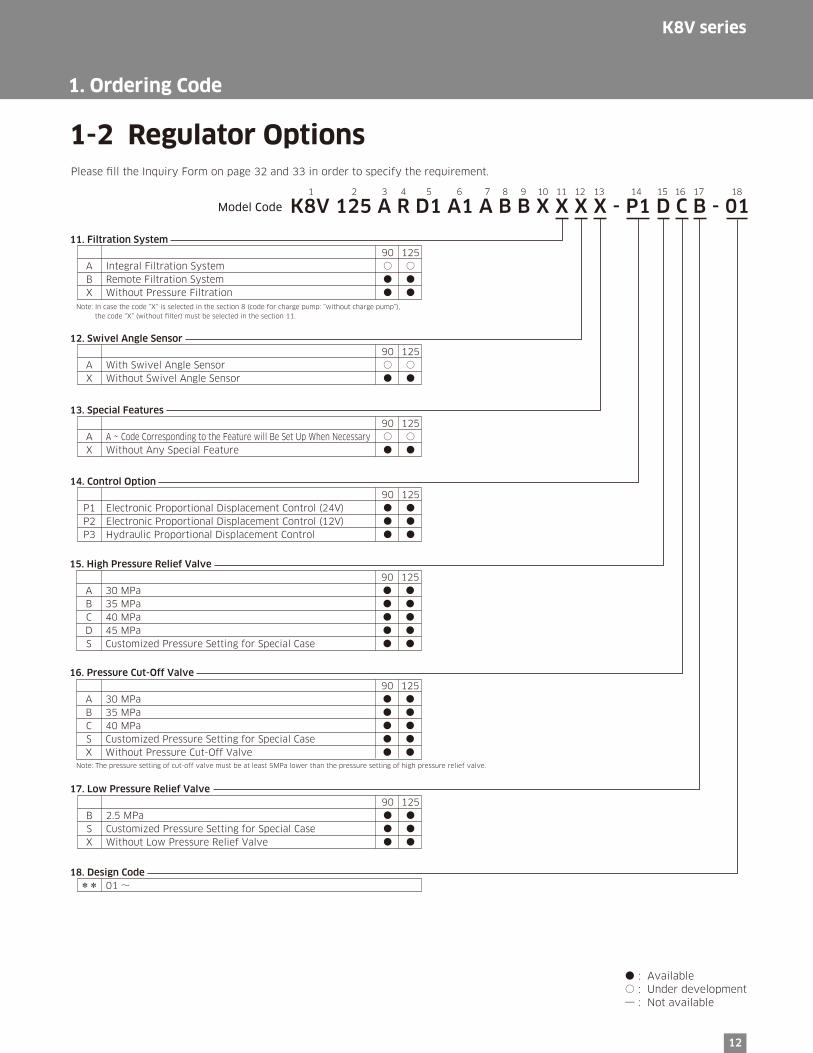
15. High Pressure Relief Valve 90 125 A 30 MPa ● ● B 35 MPa ● ● C 40 MPa ● ● D 45 MPa ● ● S Customized Pressure Setting for Special Case ● ●
16. Pressure Cut-Off Valve 90 125 A 30 MPa ● ● B 35 MPa ● ● C 40 MPa ● ● S Customized Pressure Setting for Special Case ● ● X Without Pressure Cut-Off Valve ● ●
11. Filtration System 90 125 A Integral Filtration System ○ ○ B Remote Filtration System ● ● X Without Pressure Filtration ● ●
14. Control Option 90 125 P1 Electronic Proportional Displacement Control (24V) ● ● P2 Electronic Proportional Displacement Control (12V) ● ● P3 Hydraulic Proportional Displacement Control ● ●
17. Low Pressure Relief Valve 90 125 B 2.5 MPa ● ● S Customized Pressure Setting for Special Case ● ● X Without Low Pressure Relief Valve ● ●
18. Design Code ** 01 ~
12. Swivel Angle Sensor 90 125 A With Swivel Angle Sensor ○ ○ X Without Swivel Angle Sensor ● ●
13. Special Features 90 125 A A ~ Code Corresponding to the Feature will Be Set Up When Necessary ○ ○ X Without Any Special Feature ● ●
K8V 125 A R D1 A1 A B B X X X X - P1 D C B - 01Model Code1 2 3 5 6 7 8 9 10 12 13 14 15 16 17 18114
● : Available ○ : Under development ― : Not available
Please �ll the Inquiry Form on page 32 and 33 in order to specify the requirement.
Note: The pressure setting of cut-off valve must be at least 5MPa lower than the pressure setting of high pressure relief valve.
Note: In case the code “X” is selected in the section 8 (code for charge pump: “without charge pump”), the code “X” (without �lter) must be selected in the section 11.
12
K8V series
1. Ordering Code
1-2 Regulator Options
13
2 Technical Information
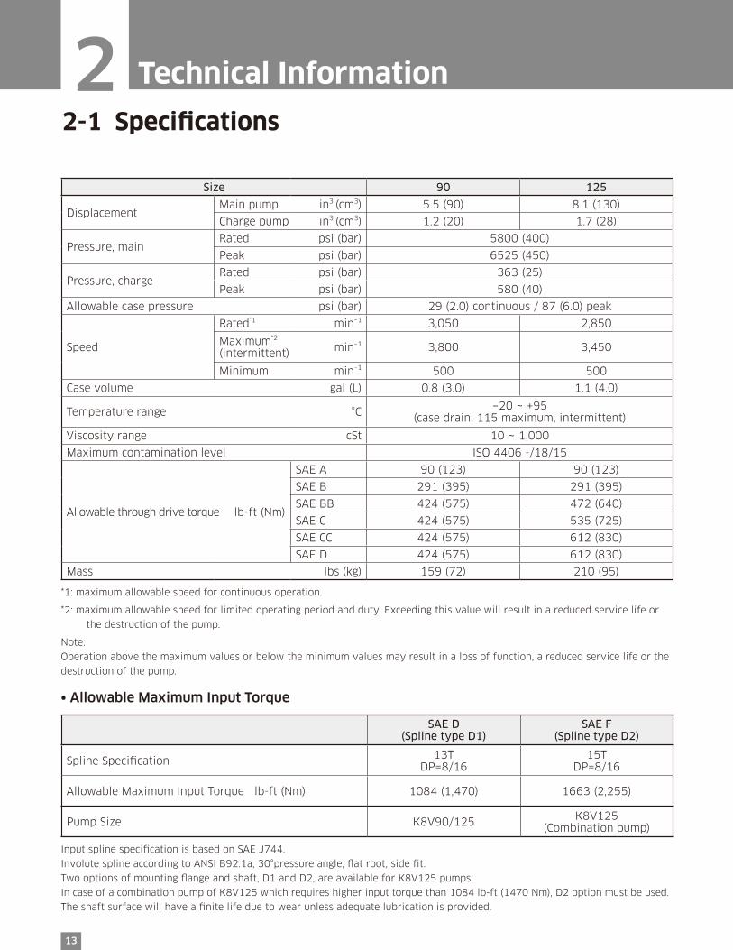
2-1 Specifications
Size 90 125
DisplacementMain pump in3 (cm3) 5.5 (90) 8.1 (130)
Charge pump in3 (cm3) 1.2 (20) 1.7 (28)
Pressure, mainRated psi (bar) 5800 (400)
Peak psi (bar) 6525 (450)
Pressure, chargeRated psi (bar) 363 (25)
Peak psi (bar) 580 (40)
Allowable case pressure psi (bar) 29 (2.0) continuous / 87 (6.0) peak
Speed
Rated*1 min–1 3,050 2,850
Maximum*2 min–1
(intermittent) 3,800 3,450
Minimum min–1 500 500
Case volume gal (L) 0.8 (3.0) 1.1 (4.0)
Temperature range °C −20 ~ +95(case drain: 115 maximum, intermittent)
Viscosity range cSt 10 ~ 1,000
Maximum contamination level ISO 4406 -/18/15
Allowable through drive torque lb-ft (Nm)
SAE A 90 (123) 90 (123)
SAE B 291 (395) 291 (395)
SAE BB 424 (575) 472 (640)
SAE C 424 (575) 535 (725)
SAE CC 424 (575) 612 (830)
SAE D 424 (575) 612 (830)
Mass lbs (kg) 159 (72) 210 (95)
*1: maximum allowable speed for continuous operation.
*2: maximum allowable speed for limited operating period and duty. Exceeding this value will result in a reduced service life or
the destruction of the pump.
Note:
Operation above the maximum values or below the minimum values may result in a loss of function, a reduced service life or the
destruction of the pump.
• Allowable Maximum Input Torque
SAE D(Spline type D1)
SAE F(Spline type D2)
Spline Specification 13TDP=8/16
15TDP=8/16
Allowable Maximum Input Torque lb-ft (Nm) 1084 (1,470) 1663 (2,255)
Pump Size K8V90/125 K8V125(Combination pump)
Input spline specification is based on SAE J744.
Involute spline according to ANSI B92.1a, 30°pressure angle, flat root, side fit.
Two options of mounting flange and shaft, D1 and D2, are available for K8V125 pumps.
In case of a combination pump of K8V125 which requires higher input torque than 1084 lb-ft (1470 Nm), D2 option must be used.
The shaft surface will have a finite life due to wear unless adequate lubrication is provided.
14
K8V series
Pressure cut-off setting(at cut-off control start)
Qset
at 1000 rpmQmax
at rated speed
Flow
Hig
h p
ress
ure
rel
ief
val
ve
sett
ing
Pre
ssure
≧ 5
MP
aO
per
atin
g pre
ssure
at p
ort
A, B
2-1 Specifications
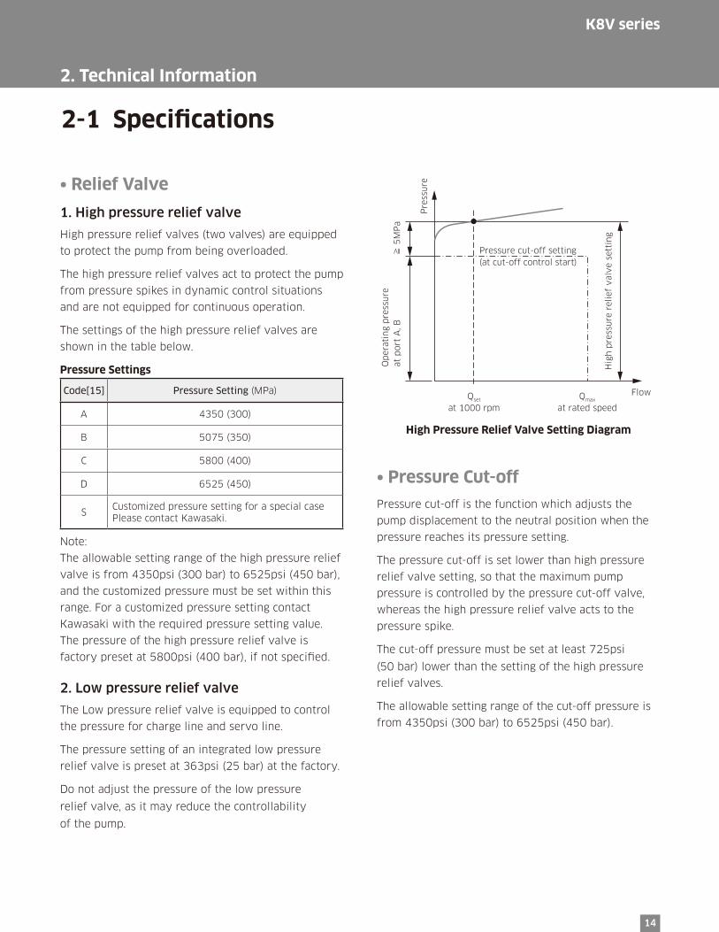
• Relief Valve
1. High pressure relief valve
High pressure relief valves (two valves) are equipped
to protect the pump from being overloaded.
The high pressure relief valves act to protect the pump
from pressure spikes in dynamic control situations
and are not equipped for continuous operation.
The settings of the high pressure relief valves are
shown in the table below.
Pressure Settings
Code[15] Pressure Setting (MPa)
A 4350 (300)
B 5075 (350)
C 5800 (400)
D 6525 (450)
SCustomized pressure setting for a special case Please contact Kawasaki.
Note:
The allowable setting range of the high pressure relief
valve is from 4350psi (300 bar) to 6525psi (450 bar),
and the customized pressure must be set within this
range. For a customized pressure setting contact
Kawasaki with the required pressure setting value.
The pressure of the high pressure relief valve is
factory preset at 5800psi (400 bar), if not specified.
2. Low pressure relief valve
The Low pressure relief valve is equipped to control
the pressure for charge line and servo line.
The pressure setting of an integrated low pressure
relief valve is preset at 363psi (25 bar) at the factory.
Do not adjust the pressure of the low pressure
relief valve, as it may reduce the controllability
of the pump.
• Pressure Cut-off
Pressure cut-off is the function which adjusts the
pump displacement to the neutral position when the
pressure reaches its pressure setting.
The pressure cut-off is set lower than high pressure
relief valve setting, so that the maximum pump
pressure is controlled by the pressure cut-off valve,
whereas the high pressure relief valve acts to the
pressure spike.
The cut-off pressure must be set at least 725psi
(50 bar) lower than the setting of the high pressure
relief valves.
The allowable setting range of the cut-off pressure is
from 4350psi (300 bar) to 6525psi (450 bar).
High Pressure Relief Valve Setting Diagram
2. Technical Information

15
• Charge Pump
Charge flow is required on all K8V pumps applied in closed-loop systems. The charge pump supplies flow to
replenish, cool and filter oil, provide charge pressure and servo pressure, and flow for system control and
auxiliary functions.
An integrated charge pump is available. The available charge pump sizes are as follows;
K8V90: 1.22in3 (20 cm3)/rev
K8V125: 1.70in3 (28 cm3)/rev
Pressure and flow for charge circuit can be supplied by an external auxiliary pump.
An auxiliary pump for charge circuit can also be mounted on the back of the main pump using a through
drive mounting.
In case the auxiliary pump is used for charge circuit, connect the charge pump delivery line to port C so that the
flow is provided to the low pressure line and servo line. The integrated low pressure relief valve can be used in this
case. If the integrated low pressure relief valve is not used, provide an appropriate relief valve in the system.
2-1 Specifications
2. Technical Information
16
K8V series
F2
F1
Hydraulic Circuit
B1 a1 A1
A2a2
(Customer's Supply)
F1 F2
a3 a4
Dr1,2
C
Hydraulic Circuit
Dr1 ,Dr2
C
A1
A2
a1
a2
a4a3
Filtration of Charge Pump
Filtration of the hydraulic fluid reduces premature wear, and enhances the reliability and life of the products.
To ensure the cleanliness of the working fluid it is essential to optimize function of the machine, and extend the
service life.
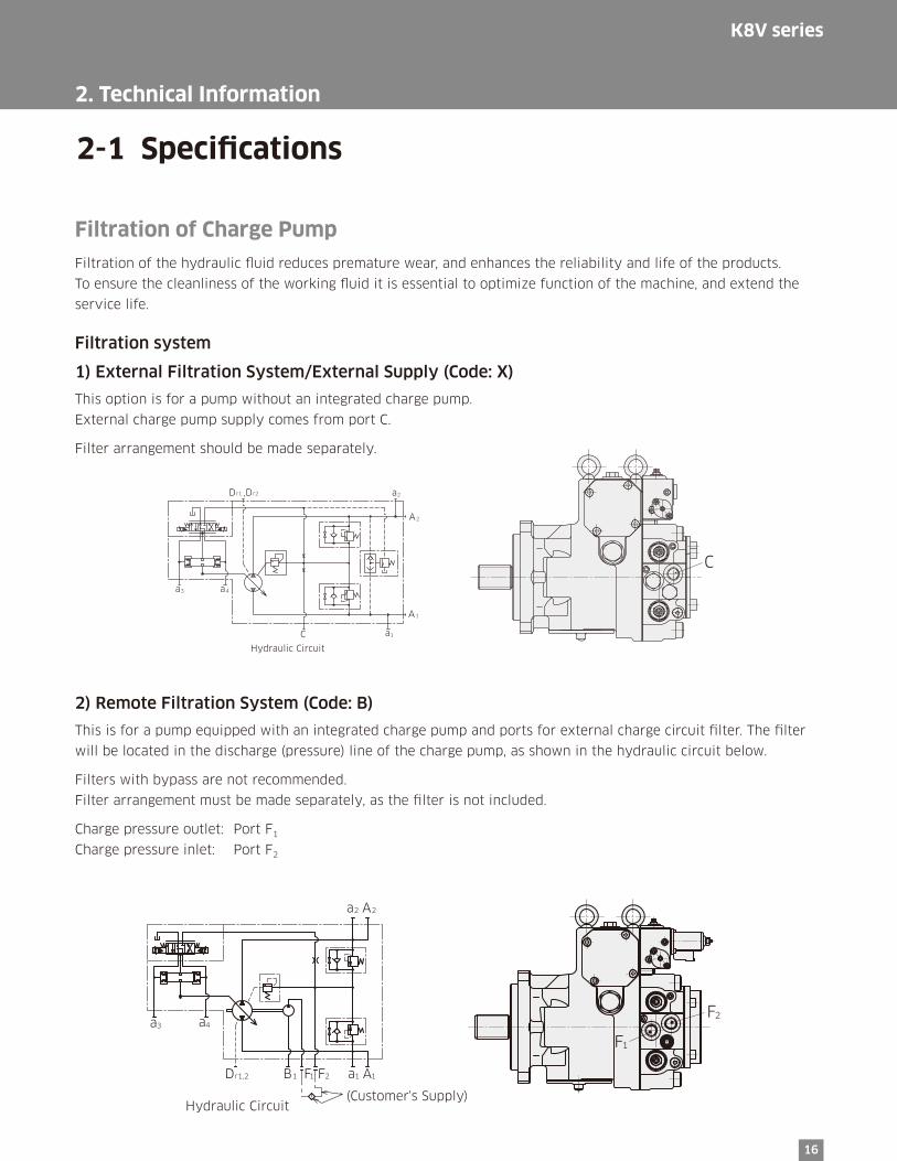
Filtration system
1) External Filtration System/External Supply (Code: X)
This option is for a pump without an integrated charge pump.
External charge pump supply comes from port C.
Filter arrangement should be made separately.
2) Remote Filtration System (Code: B)
This is for a pump equipped with an integrated charge pump and ports for external charge circuit filter. The filter
will be located in the discharge (pressure) line of the charge pump, as shown in the hydraulic circuit below.
Filters with bypass are not recommended.
Filter arrangement must be made separately, as the filter is not included.
Charge pressure outlet: Port F1
Charge pressure inlet: Port F2
2-1 Specifications
2. Technical Information

17
2-2 Functional Description of Regulator
• Electric Proportional Control (Code: P1, P2)Pump delivery flow can be proportionally controlled by the input
current to the electric proportional reducing valve equipped on
the regulator.
The input current of the electric proportional reducing valve
signals the control spool in the regulator to stroke, and to supply
pressure to the servo piston. The pump displacement varies with
the stroke of the servo piston.
The feedback lever, connected with to servo piston at one end,
moves with the stroke of the servo piston. This movement causes
the sleeve of the control spool which is connected to the other
end of the feedback lever to stroke, and closes the flow passage
to the servo piston.
Consequently, the stroke of the servo piston stops, and the pump
displacement becomes proportional to the input current.
• Electrical Specifications
Connector Type
Deutsch, DT04-2P
Rated Current and Coil Resistance
For 24 V supply: 0.7 A, 15 Ω (at 20ºC)
For 12 V supply: 1.6 A, 33 Ω (at 20ºC)
Recommended dither condition
85 Hz, 200 mAp-p for 24 V
85 Hz, 600 mAp-p for 12 V
(Note)
Electric displacement control regulator requires
the minimum servo pressure as follows.
For K8V125: 290psi (20 bar)
For K8V90: 363psi (25 bar)
The above figures are the control characteristics of electric proportional control.
The control characteristics of electric proportional control is not adjustable.
Hydraulic Circuit
2. Technical Information
100
80
60
40
20
0
Input Current [mA] A1, A2
12V supply
Dis
pla
cem
ent
[%]
0 400 800 1200 1600
100
80
60
40
20
0
Input Current [mA] A1, A2
24V supply
Dis
pla
cem
ent
[%]
0 200 400 600 800
Dr1,Dr2
B
a3 a4
a5
Control Characteristics
18
K8V series
Dr1,Dr2
B
a3 a4
a5a3 a4
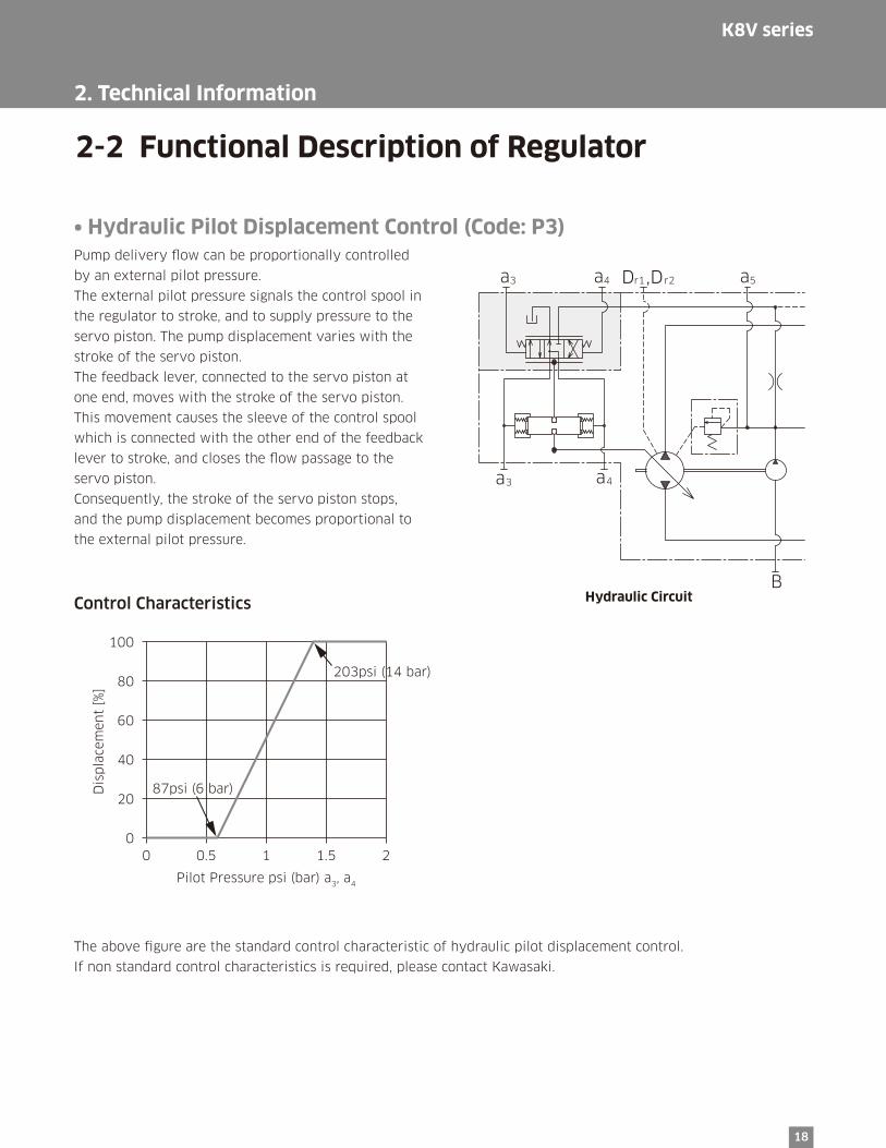
2-2 Functional Description of Regulator
• Hydraulic Pilot Displacement Control (Code: P3)Pump delivery flow can be proportionally controlled
by an external pilot pressure.
The external pilot pressure signals the control spool in
the regulator to stroke, and to supply pressure to the
servo piston. The pump displacement varies with the
stroke of the servo piston.
The feedback lever, connected to the servo piston at
one end, moves with the stroke of the servo piston.
This movement causes the sleeve of the control spool
which is connected with the other end of the feedback
lever to stroke, and closes the flow passage to the
servo piston.
Consequently, the stroke of the servo piston stops,
and the pump displacement becomes proportional to
the external pilot pressure.
The above figure are the standard control characteristic of hydraulic pilot displacement control.
If non standard control characteristics is required, please contact Kawasaki.
Hydraulic Circuit
2. Technical Information
Control Characteristics
100
80
60
40
20
0
Pilot Pressure psi (bar) a3, a4
Dis
pla
cem
ent
[%]
0 0.5 1 1.5 2
203psi (14 bar)
87psi (6 bar)
19
2-2 Functional Description of Regulator
• Mechanical Stroke LimiterBy an adjusting screw the maximum displacement can be adjusted infinitely to the required displacement setting.
This option is under development. For details contact Kawasaki.
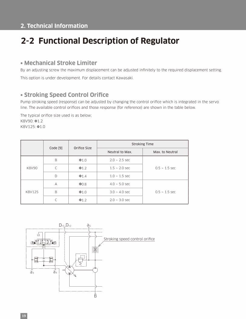
• Stroking Speed Control OrificePump stroking speed (response) can be adjusted by changing the control orifice which is integrated in the servo
line. The available control orifices and those response (for reference) are shown in the table below.
The typical orifice size used is as below;
K8V90: Φ1.2
K8V125: Φ1.0
Code [9] Orifice SizeStroking Time
Neutral to Max. Max. to Neutral
K8V90
B Φ1.0 2.0 ~ 2.5 sec
0.5 ~ 1.5 secC Φ1.2 1.5 ~ 2.0 sec
D Φ1.4 1.0 ~ 1.5 sec
K8V125
A Φ0.8 4.0 ~ 5.0 sec
0.5 ~ 1.5 secB Φ1.0 3.0 ~ 4.0 sec
C Φ1.2 2.0 ~ 3.0 sec
2. Technical Information
Dr1,Dr2
B
a3 a4
a5
Stroking speed control ori�ce

20
K8V series
3 Dimensions
3-1 Installation Dimensions
• K8V90
* Dimensions in mm.
164.5
85
85
346.5
122.5
10
2 10
6.4
±0
.2106.4±0.2
161.6±0.2
228.6±0.2
170.7 183
106
SAE “D“ 30° Involute Spline Shaft
SAE J744-44-4 13T 8/16 DP
16
1.6
±0
.2
17
9
159.5
185
245
57
.2±
0.2 27.8
A2
a2
a1
Dr1
B
±0.2
∅25
42
42
12
.5
52
.5
20
164.5
273
60
12.7 0-0.5
∅4
4.4
5 0 -0
.08
9
∅1
52
.4 0 -0
.05
45
3266
245∅25
57
.2±
0.2
27.8 ±0.2
17
122
68
.5
21
7.5
11
3
75
2-∅22
4-22
∅8
2.5
5+0
.05
+0.0
3
∅1
2.9
3
9
10.5
a
a4
a3
a5
Dr2
A1
(Note) See port details for thread size on port A1 and A2.

21
3-1 Installation Dimensions
3. Dimensions
• K8V90 Port DetailsMain Flanged Ports
Des Port Name Port Size Flange Thread
Unified Thread Version
A1, A2 Pressure Port SAE J518C high pressure (code 62) 1" 7/16-14UNC-2B-17-21.5
Metric Thread Version
A1, A2 Pressure Port SAE J518C high pressure (code 62) 1" M12-17
Auxiliary Ports
Des Port name Port size
Dr1, Dr2 Drain Port 1-1/16-2 UN-2B-19 (ISO 11926-1)
a1, a2, a3, a4 Gauge Port 9/16-18 UNF-2B-12.7 (ISO 11926-1)
B Inlet Port 1-5/16-12 UN-2B-19 (ISO 11926-1)
a5 Gauge Port 7/8-14 UNF-2B-16.7
a Air Vent Port 9/16-18 UNF-2B-12.7
F1 External Filter Port (OUT) 7/8-14 UNF-2B-16.7
F2 External Filter Port (IN) 7/8-14 UNF-2B-16.7
CExternal Charge Pressure
Supply Port7/8-14 UNF-2B-16.7
22
K8V series
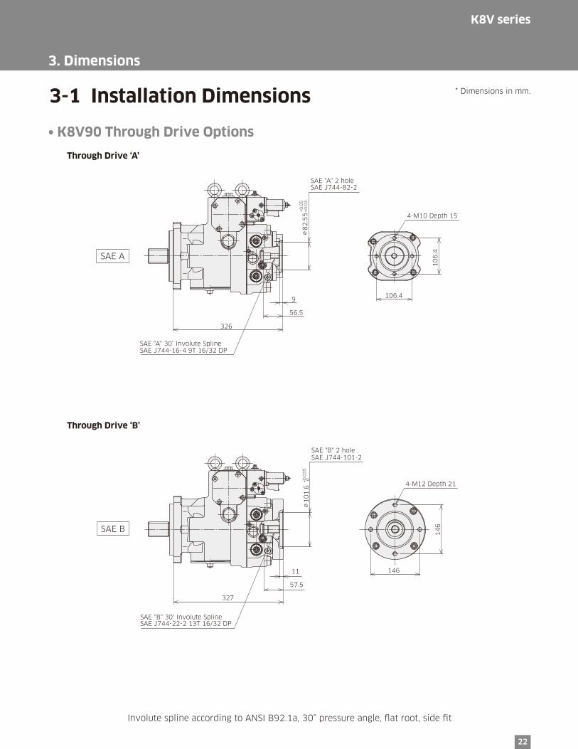
SAE "A" 2 holeSAE J744-82-2
4-M10 Depth 15
SAE "A" 30° Involute SplineSAE J744-16-4 9T 16/32 DP
326
10
6.4
106.4∅
82
.55
+0.0
5+0
.03
9
56.5
SAE A
SAE "B" 2 holeSAE J744-101-2
4-M12 Depth 21
SAE "B" 30° Involute SplineSAE J744-22-2 13T 16/32 DP
327
∅1
01
.6+0
.03
5 0
11
57.5
146
14
6SAE B
• K8V90 Through Drive Options
3-1 Installation Dimensions * Dimensions in mm.
Through Drive ‘A’
Through Drive ‘B’
3. Dimensions
Involute spline according to ANSI B92.1a, 30° pressure angle, flat root, side fit

23
(C-2)
(C-4
)
(C-4)
(C-4)
(C-2
)
4-M12 Depth 18
(C-2)
4-M16 Depth 23
SAE "C" 2/4 holeSAE J744-127-2/4
SAE "C" 30° Involute SplineSAE J744-33-4 14T 12/24 DP
334.5
15.5
61.5181
18
1
114.5
11
4.5
∅1
27
+0.0
4 0
SAE C
3-1 Installation Dimensions * Dimensions in mm.
3. Dimensions
Involute spline according to ANSI B92.1a, 30° pressure angle, flat root, side fit
• K8V90 Through Drive Options
Through Drive ‘C’
SAE "BB" 2 holeSAE J744-101-2
4-M12 Depth 21
SAE "BB" 30° Involute SplineSAE J744-25-2 15T 16/32 DP
327
∅1
01
.6+0
.03
5 0
11
57.5
146
14
6SAE BB
Through Drive ‘BB’

24
K8V series
• K8V90 Through Drive Options
3-1 Installation Dimensions * Dimensions in mm.
3. Dimensions
Involute spline according to ANSI B92.1a, 30° pressure angle, flat root, side fit
6-M20 Depth 33
(D-4
)
(D-4)
(D-2)
SAE "D" 2/4 holeSAE J744-152-2/4
SAE "D" 30° Involute SplineSAE J744-47-4 13T 8/16 DP
346.5
∅1
52
.4+0
.04
0
14
73.5
228.6
16
1.6
161.6
SAE D
(CC-2)
(CC-
4)
(CC-4)
(CC-4)
(CC-
2)
4-M12 Depth 18
(CC-2)
4-M16 Depth 23
SAE "CC" 2/4 holeSAE J744-127-2/4
SAE "CC" 30° Involute SplineSAE J744-38-4 17T 12/24 DP
334.5
15.5
60∅
12
7+0
.04
0181
18
1
114.5
11
4.5
SAE CC
Through Drive ‘CC’
Through Drive ‘D’

25
3. Dimensions
• K8V125
3-1 Installation Dimensions * Dimensions in mm.
(Note) See port details for thread size on port A1 and A2.
97
.59
7.5
182
372.5
13
64
274
31.8±0.2
66
.7±
0.2
276
∅32
212
47
.54
7.5
177
76
161.6±0.2
228.6±0.2
16
1.6
±0
.2
19
0 24
41
24
120
120
299
352
8
177
20
50
135127
11
5
106.4±0.2
10
6.4
±0
.2
187.5180
15
31.8 ±0.2
66
.7±
0.2
274∅32
∅1
2.9
3
∅8
2.5
5+0
.05
+0.0
3
9
10.5
2-∅22
4-22
A2
a2
a1
Dr1
B
Dr2
a3
a
a4
a5
A1

26
K8V series
3. Dimensions
Ø1
52
.4 0 -0
.05
228.6 ±0.2
2-∅22
4-22 60
Ø4
4.4
5 0 -0
.08
9Ø
50
.8 0 -0
.1
66
88
12.7 0-0.5
75
SAE "D" 30° Involute Spline Shaft
SAE J744-44-4 13T 8/16 DP
SAE "F" 30° Involute Spline Shaft
SAE J744-50-4 15T 8/16 DP
• K8V125 Mounting Flange and Shaft Options
3-1 Installation Dimensions * Dimensions in mm.
SAE D Spline shaft
SAE F Spline shaft

27
3. Dimensions
3-1 Installation Dimensions * Dimensions in mm.
• K8V125 Port DetailsMain Flanged Ports
Des Port Name Port Size Flange Thread
Unified Thread Version
A1, A2 Pressure Port SAE J518C high pressure (code 62) 1-1/4" 1/2-13UNC-2B-19/24
Metric Thread Version
A1, A2 Pressure Port SAE J518C high pressure (code 62) 1-1/4" M14-19
Auxiliary Ports
Des Port name Port size
Dr1, Dr2 Drain Port 1-1/16-2 UN-2B-19 (ISO 11926-1)
a1, a2, a3, a4 Gauge Port 9/16-18 UNF-2B-12.7 (ISO 11926-1)
B Inlet Port 1-5/8-12 UN-2B-24 (ISO 11926-1)
a5 Gauge Port 7/8-14 UNF-2B-16.7
a Air Vent Port 9/16-18 UNF-2B-12.7
F1 External Filter Port (OUT) 7/8-14 UNF-2B-16.7
F2 External Filter Port (IN) 7/8-14 UNF-2B-16.7
CExternal Charge Pressure
Supply Port7/8-14 UNF-2B-16.7

28
K8V series
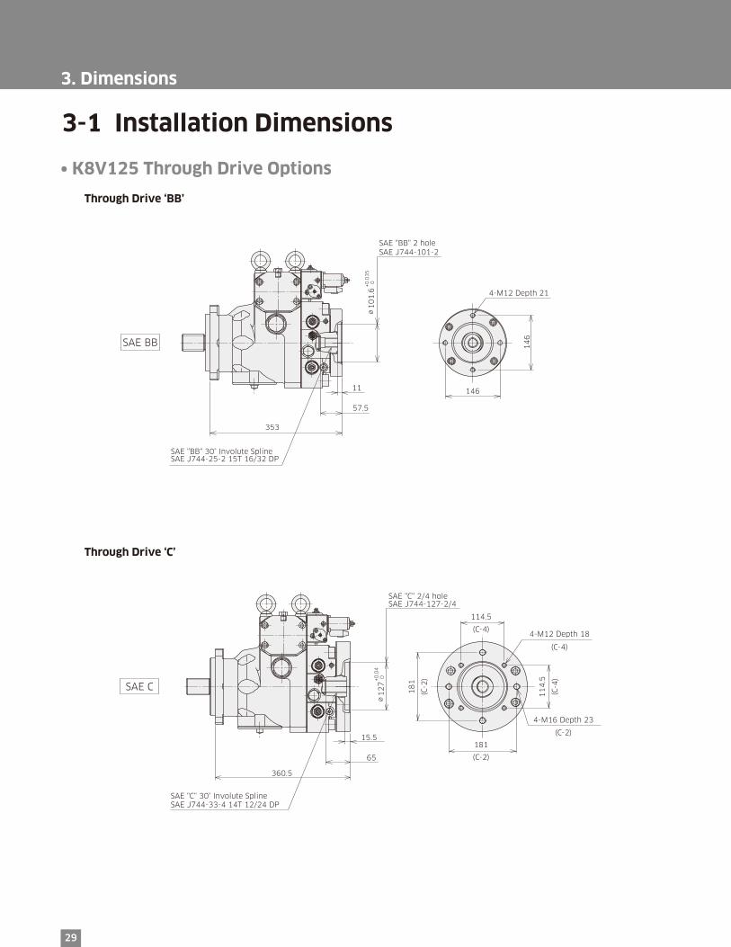
3-1 Installation Dimensions * Dimensions in mm.
3. Dimensions
Involute spline according to ANSI B92.1a, 30° pressure angle, flat root, side fit
• K8V125 Through Drive Options
SAE "A" 2 holeSAE J744-82-2
4-M10 Depth 15
SAE "A" 30° Involute SplineSAE J744-16-4 9T 16/32 DP
352
9
56.5
10
6.4
106.4∅
82
.55
+0.0
5+0
.03
SAE A
SAE "B" 2 holeSAE J744-101-2
4-M12 Depth 21
SAE "B" 30° Involute SplineSAE J744-22-2 13T 16/32 DP
353
∅1
01
.6+0
.03
5 0
11
57.5
146
14
6SAE B
Through Drive ‘A’
Through Drive ‘B’
29
(C-2)
(C-4
)
(C-4)4-M12 Depth 18
(C-4)
4-M16 Depth 23
(C-2)
(C-2
)
SAE "C" 2/4 holeSAE J744-127-2/4
SAE "C" 30° Involute SplineSAE J744-33-4 14T 12/24 DP
360.5
15.5
65
∅1
27
+0.0
4 0
181
18
1
114.5
11
4.5
SAE C
3-1 Installation Dimensions
3. Dimensions
• K8V125 Through Drive Options
Through Drive ‘C’
SAE "BB" 2 holeSAE J744-101-2
4-M12 Depth 21
SAE "BB" 30° Involute SplineSAE J744-25-2 15T 16/32 DP
353
∅1
01
.6+0
.03
5 0
11
57.5
146
14
6
SAE BB
Through Drive ‘BB’

30
K8V series
(CC-2)
(CC-
4)
(CC-4) 4-M12 Depth 18
(CC-4)
4-M16 Depth 23
(CC-2)
(CC-
2)
SAE "CC" 2/4 holeSAE J744-127-2/4
SAE "CC" 30° Involute SplineSAE J744-38-4 17T 12/24 DP
360.5
15.5
61
181
18
1
114.5
11
4.5
∅1
27
+0.0
4 0
SAE CC
6-M20 Depth 33
(D-4)
(D-2)
(D-4
)
SAE "D" 2/4 holeSAE J744-152-2/4
SAE "D" 30° Involute SplineSAE J744-47-4 13T 8/16 DP
372.5
14
73.5
∅1
52
.4+0
.04
0
228.6
16
1.6
161.6
SAE D
3-1 Installation Dimensions *Dimensions in mm.
3. Dimensions
Involute spline according to ANSI B92.1a, 30° pressure angle, flat root, side fit
• K8V125 Through Drive Options
Through Drive ‘CC’
Through Drive ‘D’
31
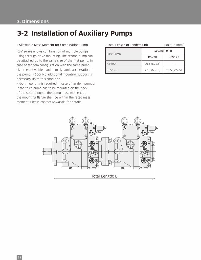
• Allowable Mass Moment for Combination Pump
K8V series allows combination of multiple pumps
using through drive mounting. The second pump can
be attached up to the same size of the first pump. In
case of tandem configuration with the same pump
size the allowable maximum dynamic acceleration to
the pump is 10G. No additional mounting support is
necessary up to this condition.
4-bolt mounting is required in case of tandem pumps.
If the third pump has to be mounted on the back
of the second pump, the pump mass moment at
the mounting flange shall be within the rated mass
moment. Please contact Kawasaki for details.
• Total Length of Tandem unit (Unit: in (mm))
First PumpSecond Pump
K8V90 K8V125
K8V90 26.5 (672.5) –
K8V125 27.5 (698.5) 28.5 (724.5)
3-2 Installation of Auxiliary Pumps
3. Dimensions
Total Length: L
32
K8V series
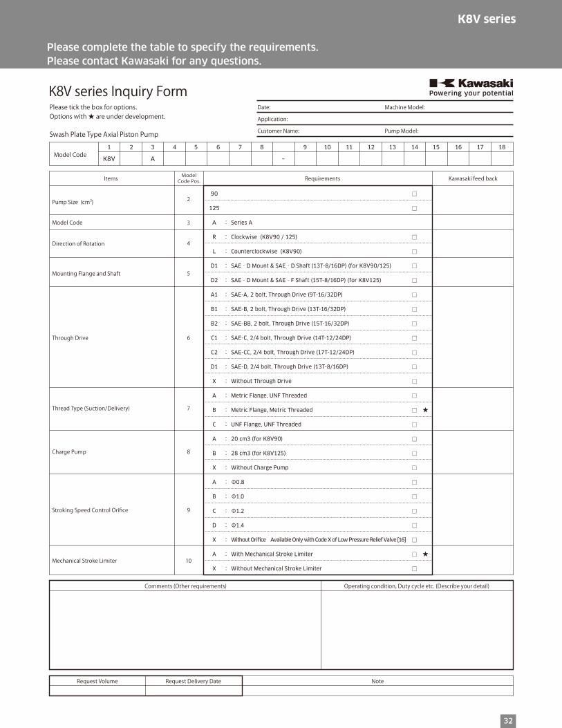
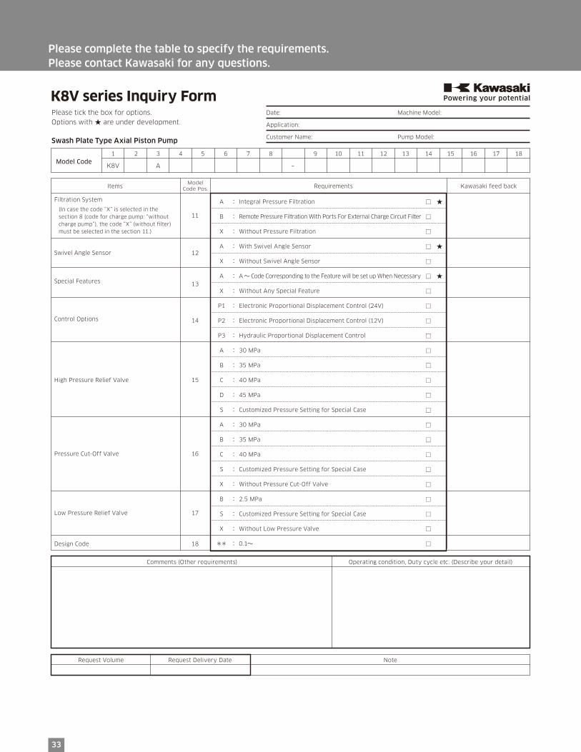
Please complete the table to specify the requirements.Please contact Kawasaki for any questions.
K8V series Inquiry FormPlease tick the box for options.Options with ★ are under development.
Swash Plate Type Axial Piston Pump
Model Code
Comments (Other requirements) Operating condition, Duty cycle etc. (Describe your detail)
Request Delivery DateRequest Volume Note
Date: Machine Model:
Application:
Customer Name: Pump Model:
1 2 3 4 5 6 7 8 9 10 11 12 13 14 15 16 17 18
K8V A –
Items Requirements Kawasaki feed backModelCode Pos.
2
3
4
5
6
7
8
9
10
Pump Size (cm3)
Model Code
Direction of Rotation
Mounting Flange and Shaft
Through Drive
Thread Type (Suction/Delivery)
Charge Pump
Stroking Speed Control Orifice
Mechanical Stroke Limiter
□
□
□
□
□
□
□
□
□
□
□
□
□
□
□
□
□
□
□
□
□
□
□
□
□
□
★
★
90
125
A : Series A
R : Clockwise (K8V90 / 125)
L : Counterclockwise (K8V90)
D1 : SAE‐D Mount & SAE‐D Shaft (13T-8/16DP) (for K8V90/125)
D2 : SAE‐D Mount & SAE‐F Shaft (15T-8/16DP) (for K8V125)
A1 : SAE-A, 2 bolt, Through Drive (9T-16/32DP)
B1 : SAE-B, 2 bolt, Through Drive (13T-16/32DP)
B2 : SAE-BB, 2 bolt, Through Drive (15T-16/32DP)
C1 : SAE-C, 2/4 bolt, Through Drive (14T-12/24DP)
C2 : SAE-CC, 2/4 bolt, Through Drive (17T-12/24DP)
D1 : SAE-D, 2/4 bolt, Through Drive (13T-8/16DP)
X : Without Through Drive
A : Metric Flange, UNF Threaded
B : Metric Flange, Metric Threaded
C : UNF Flange, UNF Threaded
A : 20 cm3 (for K8V90)
B : 28 cm3 (for K8V125)
X : Without Charge Pump
A : Φ0.8
B : Φ1.0
C : Φ1.2
D : Φ1.4
X : Without Ori�ce Available Only with Code X of Low Pressure Relief Valve [16]
A : With Mechanical Stroke Limiter
X : Without Mechanical Stroke Limiter
K8V series Inquiry FormPlease tick the box for options.Options with ★ are under development.
Swash Plate Type Axial Piston Pump
Model Code
Comments (Other requirements) Operating condition, Duty cycle etc. (Describe your detail)
Request Delivery DateRequest Volume Note
Date: Machine Model:
Application:
Customer Name: Pump Model:
1 2 3 4 5 6 7 8 9 10 11 12 13 14 15 16 17 18
K8V A –
Items Requirements Kawasaki feed backModel
Code Pos.
11
14
12
13
15
16
17
Filtration System
Control Options
Swivel Angle Sensor
Special Features
High Pressure Relief Valve
Pressure Cut-Off Valve
Low Pressure Relief Valve
18Design Code
□
□
□
□
□
□
□
□
□
□
□
□
□
□
□
□
□
□
□
□
□
□
□
□
★
★
★
A : Integral Pressure Filtration
B : Remote Pressure Filtration With Ports For External Charge Circuit Filter
X : Without Pressure Filtration
A : With Swivel Angle Sensor
X : Without Swivel Angle Sensor
A : A~ Code Corresponding to the Feature will be set up When Necessary
X : Without Any Special Feature
P1 : Electronic Proportional Displacement Control (24V)
P2 : Electronic Proportional Displacement Control (12V)
P3 : Hydraulic Proportional Displacement Control
A : 30 MPa
B : 35 MPa
C : 40 MPa
D : 45 MPa
S : Customized Pressure Setting for Special Case
A : 30 MPa
B : 35 MPa
C : 40 MPa
S : Customized Pressure Setting for Special Case
X : Without Pressure Cut-Off Valve
B : 2.5 MPa
S : Customized Pressure Setting for Special Case
X : Without Low Pressure Valve
** : 0.1~
(In case the code “X” is selected in the section 8 (code for charge pump: “without charge pump”), the code “X” (without �lter) must be selected in the section 11.)
33
Please complete the table to specify the requirements.Please contact Kawasaki for any questions.

. . . . . . . . . . . . . . . . . . . . . . . . . . . . . . . . . . . . . . . . . . . . . . . . . . . . . . . . . . . . . . . . . . . . . . . . . . . . . . . . . . . . . . . . . . . . . . . . . . . . . . . . . . . . . . . . . . . . . . . . . . . . . . . . . . . . . . . . . . . . . . . . . . . . . . . . . . . . . . . . . . . . . . . .
. . . . . . . . . . . . . . . . . . . . . . . . . . . . . . . . . . . . . . . . . . . . . . . . . . . . . . . . . . . . . . . . . . . . . . . . . . . . . . . . . . . . . . . . . . . . . . . . . . . . . . . . . . . . . . . . . . . . . . . . . . . . . . . . . . . . . . . . . . . . . . . . . . . . . . . . . . . . . . . . . . . . . . . .
. . . . . . . . . . . . . . . . . . . . . . . . . . . . . . . . . . . . . . . . . . . . . . . . . . . . . . . . . . . . . . . . . . . . . . . . . . . . . . . . . . . . . . . . . . . . . . . . . . . . . . . . . . . . . . . . . . . . . . . . . . . . . . . . . . . . . . . . . . . . . . . . . . . . . . . . . . . . . . . . . . . . . . . .
. . . . . . . . . . . . . . . . . . . . . . . . . . . . . . . . . . . . . . . . . . . . . . . . . . . . . . . . . . . . . . . . . . . . . . . . . . . . . . . . . . . . . . . . . . . . . . . . . . . . . . . . . . . . . . . . . . . . . . . . . . . . . . . . . . . . . . . . . . . . . . . . . . . . . . . . . . . . . . . . . . . . . . . .
. . . . . . . . . . . . . . . . . . . . . . . . . . . . . . . . . . . . . . . . . . . . . . . . . . . . . . . . . . . . . . . . . . . . . . . . . . . . . . . . . . . . . . . . . . . . . . . . . . . . . . . . . . . . . . . . . . . . . . . . . . . . . . . . . . . . . . . . . . . . . . . . . . . . . . . . . . . . . . . . . . . . . . . .
. . . . . . . . . . . . . . . . . . . . . . . . . . . . . . . . . . . . . . . . . . . . . . . . . . . . . . . . . . . . . . . . . . . . . . . . . . . . . . . . . . . . . . . . . . . . . . . . . . . . . . . . . . . . . . . . . . . . . . . . . . . . . . . . . . . . . . . . . . . . . . . . . . . . . . . . . . . . . . . . . . . . . . . .
. . . . . . . . . . . . . . . . . . . . . . . . . . . . . . . . . . . . . . . . . . . . . . . . . . . . . . . . . . . . . . . . . . . . . . . . . . . . . . . . . . . . . . . . . . . . . . . . . . . . . . . . . . . . . . . . . . . . . . . . . . . . . . . . . . . . . . . . . . . . . . . . . . . . . . . . . . . . . . . . . . . . . . . .
. . . . . . . . . . . . . . . . . . . . . . . . . . . . . . . . . . . . . . . . . . . . . . . . . . . . . . . . . . . . . . . . . . . . . . . . . . . . . . . . . . . . . . . . . . . . . . . . . . . . . . . . . . . . . . . . . . . . . . . . . . . . . . . . . . . . . . . . . . . . . . . . . . . . . . . . . . . . . . . . . . . . . . . .
. . . . . . . . . . . . . . . . . . . . . . . . . . . . . . . . . . . . . . . . . . . . . . . . . . . . . . . . . . . . . . . . . . . . . . . . . . . . . . . . . . . . . . . . . . . . . . . . . . . . . . . . . . . . . . . . . . . . . . . . . . . . . . . . . . . . . . . . . . . . . . . . . . . . . . . . . . . . . . . . . . . . . . . .
. . . . . . . . . . . . . . . . . . . . . . . . . . . . . . . . . . . . . . . . . . . . . . . . . . . . . . . . . . . . . . . . . . . . . . . . . . . . . . . . . . . . . . . . . . . . . . . . . . . . . . . . . . . . . . . . . . . . . . . . . . . . . . . . . . . . . . . . . . . . . . . . . . . . . . . . . . . . . . . . . . . . . . . .
. . . . . . . . . . . . . . . . . . . . . . . . . . . . . . . . . . . . . . . . . . . . . . . . . . . . . . . . . . . . . . . . . . . . . . . . . . . . . . . . . . . . . . . . . . . . . . . . . . . . . . . . . . . . . . . . . . . . . . . . . . . . . . . . . . . . . . . . . . . . . . . . . . . . . . . . . . . . . . . . . . . . . . . .
. . . . . . . . . . . . . . . . . . . . . . . . . . . . . . . . . . . . . . . . . . . . . . . . . . . . . . . . . . . . . . . . . . . . . . . . . . . . . . . . . . . . . . . . . . . . . . . . . . . . . . . . . . . . . . . . . . . . . . . . . . . . . . . . . . . . . . . . . . . . . . . . . . . . . . . . . . . . . . . . . . . . . . . .
. . . . . . . . . . . . . . . . . . . . . . . . . . . . . . . . . . . . . . . . . . . . . . . . . . . . . . . . . . . . . . . . . . . . . . . . . . . . . . . . . . . . . . . . . . . . . . . . . . . . . . . . . . . . . . . . . . . . . . . . . . . . . . . . . . . . . . . . . . . . . . . . . . . . . . . . . . . . . . . . . . . . . . . .
. . . . . . . . . . . . . . . . . . . . . . . . . . . . . . . . . . . . . . . . . . . . . . . . . . . . . . . . . . . . . . . . . . . . . . . . . . . . . . . . . . . . . . . . . . . . . . . . . . . . . . . . . . . . . . . . . . . . . . . . . . . . . . . . . . . . . . . . . . . . . . . . . . . . . . . . . . . . . . . . . . . . . . . .
. . . . . . . . . . . . . . . . . . . . . . . . . . . . . . . . . . . . . . . . . . . . . . . . . . . . . . . . . . . . . . . . . . . . . . . . . . . . . . . . . . . . . . . . . . . . . . . . . . . . . . . . . . . . . . . . . . . . . . . . . . . . . . . . . . . . . . . . . . . . . . . . . . . . . . . . . . . . . . . . . . . . . . . .
. . . . . . . . . . . . . . . . . . . . . . . . . . . . . . . . . . . . . . . . . . . . . . . . . . . . . . . . . . . . . . . . . . . . . . . . . . . . . . . . . . . . . . . . . . . . . . . . . . . . . . . . . . . . . . . . . . . . . . . . . . . . . . . . . . . . . . . . . . . . . . . . . . . . . . . . . . . . . . . . . . . . . . . .
. . . . . . . . . . . . . . . . . . . . . . . . . . . . . . . . . . . . . . . . . . . . . . . . . . . . . . . . . . . . . . . . . . . . . . . . . . . . . . . . . . . . . . . . . . . . . . . . . . . . . . . . . . . . . . . . . . . . . . . . . . . . . . . . . . . . . . . . . . . . . . . . . . . . . . . . . . . . . . . . . . . . . . . .
. . . . . . . . . . . . . . . . . . . . . . . . . . . . . . . . . . . . . . . . . . . . . . . . . . . . . . . . . . . . . . . . . . . . . . . . . . . . . . . . . . . . . . . . . . . . . . . . . . . . . . . . . . . . . . . . . . . . . . . . . . . . . . . . . . . . . . . . . . . . . . . . . . . . . . . . . . . . . . . . . . . . . . . .
. . . . . . . . . . . . . . . . . . . . . . . . . . . . . . . . . . . . . . . . . . . . . . . . . . . . . . . . . . . . . . . . . . . . . . . . . . . . . . . . . . . . . . . . . . . . . . . . . . . . . . . . . . . . . . . . . . . . . . . . . . . . . . . . . . . . . . . . . . . . . . . . . . . . . . . . . . . . . . . . . . . . . . . .
. . . . . . . . . . . . . . . . . . . . . . . . . . . . . . . . . . . . . . . . . . . . . . . . . . . . . . . . . . . . . . . . . . . . . . . . . . . . . . . . . . . . . . . . . . . . . . . . . . . . . . . . . . . . . . . . . . . . . . . . . . . . . . . . . . . . . . . . . . . . . . . . . . . . . . . . . . . . . . . . . . . . . . . .
. . . . . . . . . . . . . . . . . . . . . . . . . . . . . . . . . . . . . . . . . . . . . . . . . . . . . . . . . . . . . . . . . . . . . . . . . . . . . . . . . . . . . . . . . . . . . . . . . . . . . . . . . . . . . . . . . . . . . . . . . . . . . . . . . . . . . . . . . . . . . . . . . . . . . . . . . . . . . . . . . . . . . . . .
. . . . . . . . . . . . . . . . . . . . . . . . . . . . . . . . . . . . . . . . . . . . . . . . . . . . . . . . . . . . . . . . . . . . . . . . . . . . . . . . . . . . . . . . . . . . . . . . . . . . . . . . . . . . . . . . . . . . . . . . . . . . . . . . . . . . . . . . . . . . . . . . . . . . . . . . . . . . . . . . . . . . . . . .
. . . . . . . . . . . . . . . . . . . . . . . . . . . . . . . . . . . . . . . . . . . . . . . . . . . . . . . . . . . . . . . . . . . . . . . . . . . . . . . . . . . . . . . . . . . . . . . . . . . . . . . . . . . . . . . . . . . . . . . . . . . . . . . . . . . . . . . . . . . . . . . . . . . . . . . . . . . . . . . . . . . . . . . .
. . . . . . . . . . . . . . . . . . . . . . . . . . . . . . . . . . . . . . . . . . . . . . . . . . . . . . . . . . . . . . . . . . . . . . . . . . . . . . . . . . . . . . . . . . . . . . . . . . . . . . . . . . . . . . . . . . . . . . . . . . . . . . . . . . . . . . . . . . . . . . . . . . . . . . . . . . . . . . . . . . . . . . . .
. . . . . . . . . . . . . . . . . . . . . . . . . . . . . . . . . . . . . . . . . . . . . . . . . . . . . . . . . . . . . . . . . . . . . . . . . . . . . . . . . . . . . . . . . . . . . . . . . . . . . . . . . . . . . . . . . . . . . . . . . . . . . . . . . . . . . . . . . . . . . . . . . . . . . . . . . . . . . . . . . . . . . . . .
. . . . . . . . . . . . . . . . . . . . . . . . . . . . . . . . . . . . . . . . . . . . . . . . . . . . . . . . . . . . . . . . . . . . . . . . . . . . . . . . . . . . . . . . . . . . . . . . . . . . . . . . . . . . . . . . . . . . . . . . . . . . . . . . . . . . . . . . . . . . . . . . . . . . . . . . . . . . . . . . . . . . . . . .
. . . . . . . . . . . . . . . . . . . . . . . . . . . . . . . . . . . . . . . . . . . . . . . . . . . . . . . . . . . . . . . . . . . . . . . . . . . . . . . . . . . . . . . . . . . . . . . . . . . . . . . . . . . . . . . . . . . . . . . . . . . . . . . . . . . . . . . . . . . . . . . . . . . . . . . . . . . . . . . . . . . . . . . .
. . . . . . . . . . . . . . . . . . . . . . . . . . . . . . . . . . . . . . . . . . . . . . . . . . . . . . . . . . . . . . . . . . . . . . . . . . . . . . . . . . . . . . . . . . . . . . . . . . . . . . . . . . . . . . . . . . . . . . . . . . . . . . . . . . . . . . . . . . . . . . . . . . . . . . . . . . . . . . . . . . . . . . . .
34
K8V series
MEMO

Cat. No. KPM1606 Feb. '16
Kawasaki Precision Machinery (UK) Ltd. Ernesettle Lane, Ernesettle, Plymouth, Devon, PL5 2SA United KingdomPhone +44-1752-364394 Fax. +44-1752-364816http://www.kpm-eu.com
Kawasaki Precision Machinery (Suzhou) Ltd.668 JianLin Rd, New District, Suzhou, 215151 ChinaPhone +86-512-6616-0365 Fax. +86-512-6616-0366
Kawasaki Precision Machinery Trading (Shanghai) Co., Ltd. 17th Floor (Room 1701), The Headquarters Building, No168, XiZang Road (M), Huangpu District, Shanghai, 200001, ChinaPhone +86-21-3366-3800 Fax. +86-21-3366-3808
Kawasaki Chunhui Precision Machinery (Zhejiang) Ltd.No.200 Yasha Road Shangyu Economic Development Zone, Shansyu, Zhejiang, 312300, China Phone +86-575-8215-6999 Fax. +86-575-8215-8699
Flutek, Ltd.98 GIL 6, Gongdan-Ro, Seongsan-Ku, Changwon-Si, Kyungnam, 51567, Korea Phone +82-55-210-5900 Fax. +82-55-286-5557
Wipro Kawasaki Precision Machinery Private LimitedNo. 15, Sy. No. 35 & 37, Kumbalgodu Industrial Area, Kumbalgodu Village, Kengeri Hobli, Bangalore, – 560074 ,India
Tokyo Head Of�ce1-14-5 Kaigan, Minato-ku, Tokyo 105-8315, JapanPhone +81-3-3435-6862 Fax. +81-3-3435-2023
Kobe Head Of�ceKobe Crystal Tower, 1-3 Higashikawasaki-cho 1-chome, Chuo-ku, Kobe 650-8680, Japan Phone +81-78-360-8607 Fax. +81-78-360-8609
Nishi-kobe Works234, Matsumoto, Hasetani-cho, Nishi-ku, Kobe 651-2239, JapanPhone +81-78-991-1160 Fax. +81-78-991-3186
Precision Machinery Company
http://www.khi.co.jp/kpm/
Kawasaki Precision Machinery (U.S.A.), Inc.3838 Broadmoor Avenue S.E. Grand Rapids, Michigan 49512, U.S.A.Phone +1-616-975-3100 Fax. +1-616-975-3103http://www.kpm-usa.com
OVERSEAS SUBSIDIARIES
Materials and speci�cations are subject to change without manufacturer's obligation.
QR codePrecision MachineryCompany Website