Embed Size (px)
Citation preview

Ac - Al-~ -- r-----~--r'- ~ ~ -AA~ - -n~AAAA A-A ~ A- AA~
A.
2 K)N 0 A -
/A-..4? A,~ - -
4'I A
C
*0-A jt Irnpedance~ of LOFTI IRA VeryebowaFwtuenoy
ti.anrza*TflVSO lru .tflflflflflntA~tJa AK0 - I" A IV'
~ AC. A - *<A 03
-~ CtAOPNp A NVAAA IP.A A A '2 - A12 A 7A AC A '2 - - A
-~ Sgelli4tCppunvnkws~nErawh -A(A Afl:,' 'A - - -r
A' '-A~z.aat4 Thasson A - -
jA t A ;AZ CA A - - 2<
v ~9 ~A
' A 1K-~ A ~-- ~AZ,, 'A.A
A Ak A 'A - - A
A A A A -
A - - AA -. A 2
A <A
- A A
- CA A~ A
AQA 'A -~1- A A -
~ I/n A.AAA A A -
A -
0 2ic-A AAA~V A(A A. - -
A A A~ -
A - .j A
A' A AP c> AAVAAA. 7 - IAAA A V A- -1 A 'AA A -- tAC.~'A -- - Al
A A~*~ AA . -A A
___ -~- - - ~ _ I A/ - ~AAir~: ~- A
A 1 A1~A A *A (A
4 V4 ~ CA - A A~ A~ A >4 A ~~Jt;iri
to 'A
A A I citI~AAAA >2
-- A A (A A- NAVAL E SEPt11 LAIOMIOJIY - A A A
A A Wg~ng1XC, A AA A (A A A
'A-
-At - 12I4 dcatmentahac* afl~wg4 IarwtQs, nYse. ~ M3~ Ltit4t~4jtdIztZ4'A C - 4

CONTENTS
Abstract iiiProblem Status iiiAuthorization iii
INTRODUCTION 1
* ANTENNA INSTRUMENTATION 1
ATTITUDE INSTRUMENTATION 1
SPACECRAFT ORBIT 2
ANTENNA ORIENTATION 2
ADMITTANCE OF THE MAGNETIC-DIPOLE ANTENNA 3
EFFECT OF ENVIRONMENT ON LOOP-CIRCUITCHARACTERISTICS 3
EQUIVALENT IMPEDANCE OF THE ELECTRIC-DIPOLEANTENNA 4
DIPOLE-ANTENNA COUPLING 6
CALIBRATION OF THE DIPOLE-ANTENNA COUPLING CIRCUITS 6
SIGNAL INTERFERENCE DURING ANTENNA ADMITTANCEMEASUREMENTS 8
DAYTIME ELECTRIC-DIPOLE ADMITTANCE 8
NIGHTTIME ELECTRIC-DIPOLE ADMITTANCE 8
EFFECT OF ORIENTATION IN THE GEOMAGNETIC FIELD 10
CHANGE OF ADMITTANCE WITH ALTITUDE 11
WAVE IMPEDANCE AND E/H RATIO IN SPACE 11
COMPARISON OF LOOP AND WHIP-DIPOLE-ANTENNA-SYSTEM SIGNAL OUTPUT 11
TYPICAL D AYllVT DAA 12
COMPARISON OF DAY AND NIGHT ADMITTANCE OF THEWHIP DIPOLE 13
F, __ _

VARIATJON OF VLF DIPOLE ADMITTANCE WITHTHE SPIN AXIS PERPENDICULAR TO THEGEOMAGNETIC FIELD (ML = 0) 13
VARIATION OF VLF DIPOLE ADMITTANCE WITH THESPIN AXIS PARALLEL TO THE GEOMAGNETICFIELD (MT = 0) 16
VARIATION OF APPARENT CAPACITANCEWITH ALTITUDE 16
CONCLUSIONS 17
RECOMMENDATION 19
ACKNOWLEDGMENTS 19
REFERENCES 20
BIBLIOGRAPHY 20
1*

ABSTRACT
The spacecraft of the LOFTI IIA t r a n s i o n o s p h e r i c very-low-frequency (vlf) receiving experiment was fitted with relatively simpleaultmatic instrumentation for periodic indication of vlf antenna admit-tance in the 10 to 18 kHz range. Analysis of part of 'he resulting datahas shown the following:
1. The admittance of the vlf magnetic dipole (a D-shaped, shieldedloop approximately equivalent in capture area to a 14-in.-diatneter cir-cular coil) was essentially unaffected by the change in environment ofthe spacecraft from the earth's surface to the ionosphere. Variationsof local electron density in the ionosphere and change of antenna ori-entation rolative to the g e o m a g n e t i c field had no discernible effect.
2. The admittance of the vlf electric dipole (two 20-ft-long op-posed whips) remained capacitive, but the apparent capacitance variedmarkedly as the spacecraft moved along its orbital path. Ac much as10 to 20 times free-space value was indicated at a; udes shown bypublisbed typical data as likely regions of greatest electron density. Athigh ele:tron-density levels, a Iwo-to-one cyclic variation of capaci-tance was evident with change of dipole orientation relative to 'he geo-magnetic field as the spacecraft rotated on its spin axis At altitudesof likely low electron density, variation with spin decreased and thecapacitance approached that expected in free space.
PROBLEM STATUS
This is a final report on one phase of the problem; work continueson other phases.
AUTHORIZATION
NRL Problem R01-34Project RF 006-02-41-4353
Manuscript submitted February 16, 1968.
;
ii
IMPEDANCE OF LOFTI IIA VERY-LOW-FREQUENCYANTE1INAS IN THE IONOSPHERE
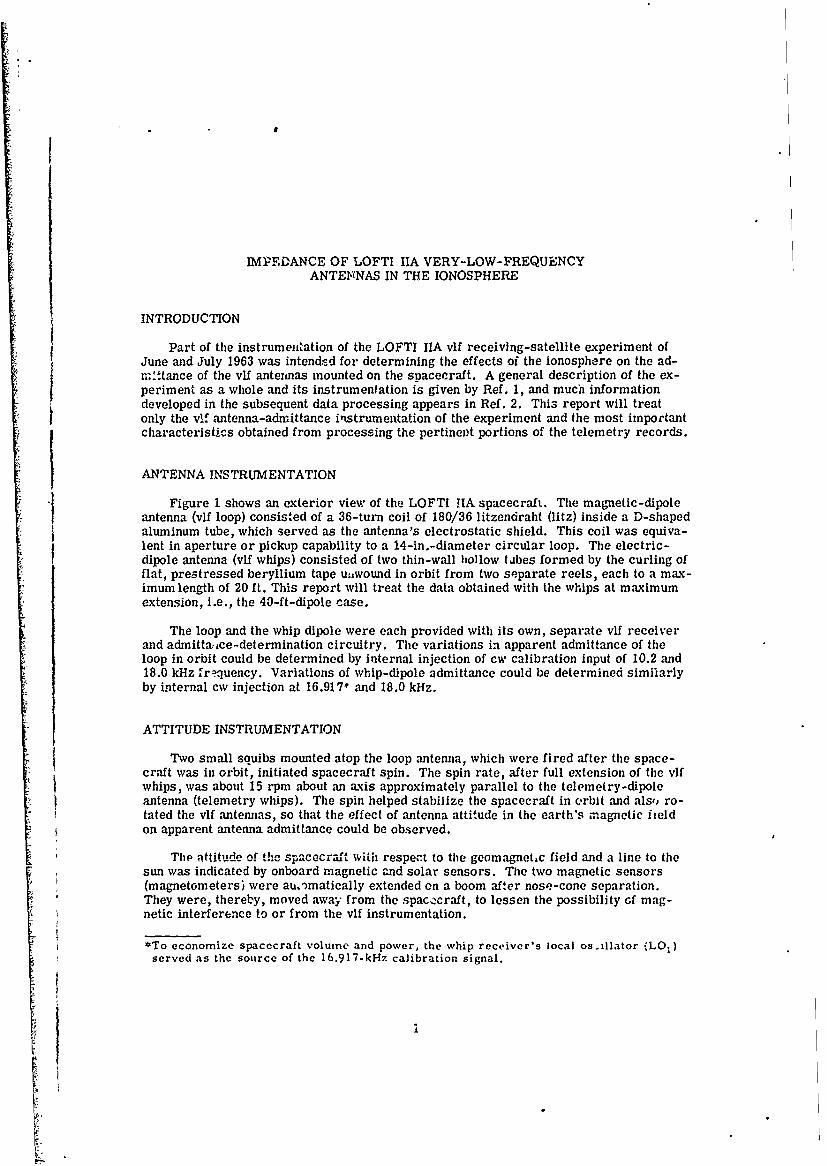
INTRODUCTIONPart of the instrumentation of the LOFTI IIA vlf receiving-satellite experiment of
June and July 1963 was intendsd for determining the effects of the ionosphere on the ad-
mrttance of the vlf antenas mounted on the spacecraft. A general description of the ex-periment as a whole and its instrumentation is given by Ref. 1, and much informationdeveloped in the subsequent data processing appears in Ref. 2. This report will treatonly the vif antenna-admittance itstrumentation of the experiment and the most importantcharacteristics obtained from processing the pertinevt portions of the telemetry records.
ANTENNA INSTRUMENTATION
Figure 1 shows an exterior view of the LOFTI HA spacecraft. The magnetic-dipoleantenna (vlf loop) consisted of a 36-turn coil of 180/36 litzendraht (litz) inside a D-shapedaluminum tube, which served as the antenna's electrostatic shield. This coil was equiva-lent in aperture or pickup capability to a 14-in.-diameter circular loop. The electric-dipole antenna (vlf whips) consisted of two thin-wall hollow tabes formed by the curling offlat, prestressed beryllium tape u.,wound in orbit from two separate reels, each to a max-imum length of 20 ft. This report will treat the data obtained with the whips at maximumextension, i.e., the 40-ft-dipole case.
The loop and the whip dipole were each provided with its own, separate vlf receiverand admittaice-determination circuitry. The variations in apparent admittance of theloop in orbit could be determined by internal injection of cw calibration input of 10.2 and18.0 kHz frn'quency. Variations of whip-dipole admittance could be determined similarlyby internal cw injection at 16.917* and 18.0 kHz.
ATTITUDE INSTRUMENTATION
Two small squibs mounted atop the loop antenna, which were fired after the space-craft was in orbit, initiated spacecraft spin. The spin rate, after full extension of the vifwhips, was about 15 rpm about an axis approximately parallel to the telemetry-dipoleantenna (telemetry whips). The spin helped stabifize the spacecraft in crbit and also ro-tated the vlf antennas, so that the effect of antenna attitude in the earth's magnetic fieldon apparent antenna admittance could be observed.
The attitude of the spacecraft with respect to the geomagnet.c field and a line to thesun was indicated by onboard magnetic and solar sensors. The two magnetic sensors(magnetometers) were au, )matically extended on a boom after nose-cone separation.They were, thereby, moved away from the spacecraft, to lessen the possibility of mag-netic interference to or from the vlf instrumentation.
*To economize spacecraft volume and power, the whip receiver's local os-,llator (LO)served as the source of the 16.917-kHz calibration signal.
Io

2 C. E. YOUNG
SI
NTEN Ni
Figure 2 lists the initial orbital elements of LOFTI IIA and depicts the changing ori-entation of the vif antennas as the spacecraft moved along its crbital path while rotating
around its spin axis, The lifetime of the spacecraft was about 32 days.
ANTENNA ORIENTATION
Figure 3 depicts the contours of the geomagnetic field in ,cross-section and showsthe variations of the spacecraft's magnetic-sensor indications as they might appear dur-
ing one orbital period. When the spin axis (essentially the axis of the telemetry antenna,whips 2 and 4) was paralle'l to the local geomagnetic field, the output of the longitudinalsensor ML would be maximum and that of the transverse sensor MT practically zero.
When the spin axis was essentially perpendicular to the geomagntic field, the MT varia-
tion would be maxiu and tiat oi the IVL ciose to zero. -Therefore, whenever the ML indication in the telemetry data was very small or aboutzron its sn assmedthat the axis of the vf whip dipole was then spinning from prac-tically parallel to perpendicular to the geomagnetic field. Conversely, when ML was max-imum and MT close to zero, it could be assumed that the axis of the vtl whip dipole wasessentially perpendicular to the field irrespective of spin.cls t eo

NRL REPORT 6712 3
N
4
EOUATOR~
4\ 4..-MAGNETOMETERS
WHIPS 1 8 3 - VLF DIPOLE S
WHIPS 2 8 4 - TELEMETRY DIPOLE
ANTENNA
Fig. 2 - Variation of LOFTI IIA antenna orientation along the orbital path. Theinitial orbital elements of LOFTI IIA were an inclination of 70 degrees, an apogeeof 925 km, a perigee of 170 kin, and a period of 96 min.
ADMITTANCE OF THE MAGNETIC-DIPOLE ANTENNA
The loop inductance (943ju H) was part of a two-pole four-element network (Fig. 4)simultaneously resonant at 10.2 and 18.0 kHz. In-orbit loop admittance at these two fre-quencies was determined by observation of the two receiver outputs during periodic inter-vals of 10.2 or 18.0 kHz cw calibration input into the antenna circuit.
EFFECT OF ENVIRONMENT ON LOOP-CIRCUITCHARACTERISTICS
A loop winding and a conductive (electrostatic) shield can be considered, in effect,as the secondary and primary, respectively, of a tightly coupled transformer. The sec-ondary is usually tuned to resonance at a desired frequency by a capacitor of appropriatevalue. The shield (primary) cannot short-circuit the secondary despite the close mag-netic coupling between them, because of an insulated gap. If the loop were immersed ina conductive medium, such as the ionosphere, this gap would be shunted by the ionizedplasma. Since the effective admittance of such a medium can be much l--rger than t. t offree space, both the resonant frequency and the Q of the tuned secondary could be ex-pected to change to a degree dependent on the characteristics of the plasma in theparticular region.
The effect of shield-gap shunting was experimentally determined in the laboratorybefore the LOFTI IIA spacecraft was launched. Capacitors and resistors of a wide rangeof values were connected in turn across the gap in the shield. As shown by Fig. 5, a shuntsusceptance of 0.5 mho (2-ohm capacitive reactance) or a conductance of 0.2 mho (5-ohmresistance) decreased the amplitude of loop-circuit response (i.e., the voltage appearil.at the loop-coupling-circuit output terminals with calibration input) by 10('.

4 C.E. YOUNG
- ~~~ -t77'-~-
4-Jb~2. _j.~/- /~~
A v~-:
A. 4i- ,'.i
'ML(+~' 4': ~ ~L(~ L4' '
-O E K *.N' -- '
Fig 3x"aito:f'h antmte uptwt tesaerf
sured on thegrondthrohot the lif toneim r of uwt the spacecraft
EQUIVALENT IMPEDANCV, OF THE ELECTRIC-DIPOLEANTENFA
j Figure 6 shows the free-space-series impedance components of an idealized 40-ftelectric dipole at 18.0 kHz, calculated using formulas by Schelkunoff (3). The capacitivereactance X, (approximately 300,000 ohms) is greater than the other conipontmts of the

w 100
-
€[ I- --I . . . . I
-_ .A
I 0 I .0 W t. O S L L A TO N $ -
0 1
Uia--
LOOP SHIELD
I IN-SU D GAP . .-- 36 TURNS OF -AT 180 STRAND/, ,e
< LITZ WIRE
I *
0.11 10 12 14 -6 Is 20 22 24 264/FRLOUENCY ELO
Fig. 4 - Frequency response of the loop system to constant -intensi~yradi-o field (terrestrial measurement)
7_ I I
2:SHUNT R ONL
0 40
CON OUCTA N ,W O P Az / ( N O S H U N TS ) I r ~--5OG. MO$ (LY-J i0 o i S Z )' I I i i i ,, , , ,2 0 - I I , , , , _I I1 11 1 "iII j I
001 01 I0 20ADMITTANCE OF R OR C. MHOS SHUNTED ACROSS LOOP .ELD GAP
Fig. 5 - Effect of a shunt across the loop-shield gap

6 C. E. YOUNG
to--- 20 ,, -1 1- to FtT -4-.
2LV4Cr. jI z(I '1 22W
C L .,dA L-1 "
, ) A 4
Fig. 6 - Computed free-space impedancecomponents of a 40-ft dipole
impedance by six orderi. a: more. It therefore appears that around 18.0 kHz, and in freespace, such an antenna would appear to be essentially a low-loss condenser of about 27 pF.
However, the actual antenna, consisting of the two diametrically opposed 20-ft whipsextending from the spacecraft, would not be electrically as simple as the idealized 40-ftdipole of Fig. 6. The approximately 2-ft-diameter body of the spacer raft separated thewhips physically, interposing a curved common-ground plane of considerable area be-tween their nearer ends. In effect, the spacecraft carried two 20-ft-long opposed mono-poles that served as a dipole which would probably have somewhat less than 27-pF c-pac-itance in free space (4).
DIPOLE-ANTENNA COUPLING
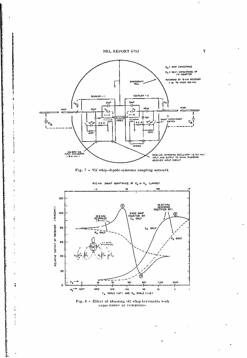
Each vlf whip was provided with a coupling network located inside the hull of thespacecraft (Fig. 7). in designing these networks, the likely minimum value of the mono-pole, or half-dipole, capacity, CA, in orbit was assumed to be 75 pF, and the likely max-imum was assumed to be 3000 pF. The coupling networks were identical and designed toresonate at 18.0 kHz, when CA was 75 pF, and at 16.917 kHz, when CA was ?%C^V pF.
While the spacecraft was in orbit, the whip-dipole-antenna-admittance determinationswere made periodically at 16.917 and 18.0 kHz. The response of the whip-dipole networkto 16.917-kHz cw excitation was indicated by the rectified radio frequency (rf) output, i.e.,the direct current change of a detector. The response to the 18.0-kHz excitation was in-dicated by the 25-Hz i-f output of the receiver.
CALIBRATION OF THE DIPOLE-ANTENNACOUPLING CIRCUITS
Figure 8 shows the voltage output of the whip-dipole network with simultaneous shunt-ing of the whip input terminals of the coupling networks by either identical external ca-pacitors CA or resistors R A. The whips themselves were not connected in circuit. Thedeterminations were made in the laboratory prior to spacecraft launch. CA ranged invalue from 0 to 10,000 pF, and RA ranged from 10 megohms to 1000 ohms.
!
NRL REPORT 6712 7
CAZ WHIP CAPACITANCE
CS SLF- CAPACITANCE OFI H INDUCTOR
PASSBANO OF lb kHz RECEIVER
SPACC~tFT__---- ZdC TO OVER 100 k34z
CCVPLER - I COUPLER - 2
I 33pF 339
F
T4T WHIPWHIP 4OPF CS CS 4OpF
-- I-3p 3
18 O~ z SHUNT TT O CALE H UN CAPACITANCE CATTCA If Op
10 OO
SPARES
INPUT CTNNECTORI is0 kHz RECEIVER KETROOTNE OSCIL.LATOR f I6 91? &HZ I
NPJT.AND OU!PJ! TO 189AC WIHIPANDRECEIVER INPUT CIRCUIT
Fig. 7 -Vif whip-di pole -antenna coupling network
18 0 kHz SHUNT ADMITTANCE OF CA or RA (AMOS)
10 t0 too 11'
120
M6.917 kHz0A RESPONSE
-(CIFE R-F)100 -EACH WHIP IETFE F
180 kHz SHUNTED BY
H ',* RESPONSE CA' ONLY
so0 _ CA ONLY
034~R --- =-- \4,ONL
%\ /60r U RA ONLY
I- N,, ,,, /
,40 C. I
- I Ii IRA 30 0 300 300 10 3 j
CA SCALE (pF) AND RA SCALE (k)
Fig. 8 - Effect of shut ing vlf whip terminals v.ithcapacitance or resistance

8 C. E. YOUNG
The solid and dashed lines represent the effect of capacitance and resistance shunt-ing, respectively, on antenna-network response (output voltage). It can be seen that boththe total change and the rate of change of output (measuremenreqluin) were largerwith capacitive shunting. The values at the inflection points ((,(2),(,) )are of particularinterest; these occur only with capacitive shunting. Resistive shunting (over the four-order range of the laboratory calibration) caused only a gradual decrease of response,with no sharply defined inflections. Occurrence of readings at point &,(9), or ( )in thein-orbit data would therefore, tend to indicate that the dipole admittance was then es-sentially capacitive.
SIGNAL INTERFERENCE DURING ANTENNAADMITTANCE MT ASUREMENTS
Search of the LCFTI data records revealed that the 18.0-kHz admittance data for thevlf whip dipole in the nighttime ionosphere were almost always obscured by relativelyvery large 18.0-kHz vif signals and noise from terrestrial sources. However, the 16.917-kHz data were not as seriously affected, probably because of larger injection voltage andlower sensitivity at that frequency.
DAYTIME ELECTRIC-DIPOLE ADMITTANCE
Whip-dipole calibration data at 18.0 kHz obtained during daylight pases were not socompletc-ly obscured by external signals. The additional attenuation of tht ionized "D"layer in the sunlit part of the atmosphere was apparently sufficient to sub ;tantially de-crease terrestrial vlf signal-and-noise intensity at the spacecraft. The riinimum 18.0-kHz response (17C, region @ )could be seen occasionally in the data, indicating thatdipole admittance was predominantly capacitive. If the plasma that surrounded the vlfwhips had had appreciable resistive shunting effect, the response observed would likelyhave been in the 80 to 40% range. At no time was the 18.0-kHz response in the region (-)range when the spacecraft was in daylight. The 16.917-kHz calibration response occa-sionally approached region® values (where the whip-dipole network would resonate withCA = 3000 pF) but was usually below this value except when the spacecraft approached theaurora regions at the higher latitudes.
NIGHTTIME ELECTRIC-DIPOLE ADMITTANCE
Figure 9 shows typical data from the records of a nighttime pass of the spacecraftover Panama at 217 to 236 km altitude. The five time frames shown are within a 3-minperiod at about 1 a.m. local mean ,.-e. Magnetic-sensor output is shown in the upperhalf of each frame. The changing value of apparent antenna capacitance, indicated by the16.917-kHz response of the whip-dipole network, is marked in the lower half of each frame.
In frame 01] of the sequence, the 16.917-kHz-output trace indicates a steady low valueof admittanze (response about 15%). Radio station NBA's 18.0-kHz signals and some vlfnoise can also be seen. The antenna admittance appears to be essentially constant, eventhough the magnetometer-output traces indicate continual spin of the spacecraft. The lowand invariant response, regardless of dipole orientation, may be interpreted as evidenceof a relatively low level of electron density in that part of the ionosphere.
The dipole capacitance appears to be approximately 38 pF (CA = 75 pF), which is about40% greater than the calculated capacitance of the 40-ft dipole in free space. The observed

NRL REPORT 6712
ifi
~~0
I' IK'
0 C
7 •
-~.

10 C.E. YOUNG
response is near the minimum obtained in the 16.917-kHz laboratory calibration (Fig. 8).*Similar low readings,indicating apparent capacitance tobe not much greater than free-space value, occur frequently in the night data of the experiment whenever the spacecraftaltitude was in the vicinity of 200 km.
In frame M of Fig. 9 (approximately 1 min later than frame 01 ), the response hasincreased to about 18'1 but still shows no apparent indication of dipole admittance vari-ation due to changing orientation in the geomagnetic field. This reading represents acapacitance value somewhat greater than 100 pF.
In frame [] , about 1.5 min after the start of the sequence, the response has furtherincreased and is beginning to vary at twice the spin rate. The appearance of this variation,the larger capacitance indicated by the higher response level, and the drop in ML lead tothe conclusion that the spacecraft has moved to a region of appreciably higher electrondensity and that its oricatation relative to the geomagnetic field has changed. The mini-mum capacitance in the frame 2 interval is apparently near 155 pF, and the maximum isabout 240 pF.
EFFECT OF ORIENTATION IN THE GEOMAGNETIC FIELD
All the data examined (day or night passes) show little effect of spacecraft spin onwhip-dipole admittance when the apparent dipole capacitance approaches the free-spacevalue. In frames r and C5 of Fig. 9, where the apparent capacitance approaches 10 timesthis value, the effeL. of change of antenna orientation relative to the geomagnetic field canbe seen very clearly.
From study of the bibliography, it appears that the theoretical predictions of dipoleadmittance in a magneto-ionic medium do not completely agree. Most of the sources con-clude that vlf dipole admittance should be maximum when the dipole axis is pfrpendicularto the geomagnetic field and minimum when parallel to the field, with a variation overseveral orders of magnitude, if direct contact to the medium is achieved, i.e., no plasmasheath. However, the experiment did not verify this prediction.
In frames [], I , and [], the apparent capacitance of the antenna is not quite maxi-mum when the MT magnetometer reading reverses polarity (zero crossing) and is notquite minimum when the magnetometer reading is maximum. The time displacementbetween the magnetometer-output maximum and apparent capacitance minimum, statedin terms of relative phase, is about 25 degrees in these three frames. This effect may beascribed to a number of possible causes, for instance, in some part to a plasma sheathsuch as forms around moving objects in the ionosphere (5). This sheath may be modifiedcyclicly to some degree as the potentials induced in the antennas and hull change withspacecraft spin and translation through the geomagnetic field.
The ratio of maximum-to-minimum capacitance appeared to be dependent uponcieLtron-density and geomagnetic-field intensity but did not exceed a ratio of two-to-onein either day or night data. The variation in amplitude of the alternate capacitance max-ima, shown in frames g] and j], was only evident in the nighttime data.
*Because of telemetry distortion and instabilities, the data resolution of the experimentwas about ± Z%, which would translate into a possible capacitance range of 57 to 93 pFfor a 15o response reading.
ii
NRL REPORT 6712
CHANGE OF ADMITTANCE WITH ALTITUDE
During the applroximately 3-min sequence of Fig. 9, the spacecraft traversed a dis-tance of about 750 naut mi, and its altitude increased from 217 to 236 kin. As alreadymentioned, the large increase in apparent capacitance of the whip dipole indicates thatthe spacecraft moved, in this short time, from an environment of low electron densityinto one of relatively high electron density.
Local electron concentration was not specifically determined in the LOFTI experi-ments. Typical electron-density profiles of the nighttime ionosphere show that electronconcentration increases rapidly with increase in altitude in the 215 to 240 km region. Forinstance,Ref. 6 indicates that an increase from about 103 electrons/cm3 near 200 km toa maximum of about 2(105) electrons/cm3 near 300 km might be expected. (Such a changeis shown by the night electron density profile in a later figure.)
WAVE IMPEDANCE AND E/H RATIO IN SPACE
In a free-space environment, the field intensity of the magnetic component of a radiowave (as indicated in this case by loop signal output) is rclated to the correspondingelectric-field intensity by the wave impedance of free space (Z0 = E/H = 120W ohms); i.e.,E = ZOH =12077 H. where E is expressed in volts per meter (V/m) and H in amperes permeter (Am). If both the loop and the whip-dipole circuits are tuned to the same signalfrequency and are immersed in a medium which approximates free space, the loop-circuit-signal output voltage should equal the whip-dipole-circuit-signal output voltage,if the two antenna systems have about the same effective output impedance and the sameeffective height or aperture. If this is not the case, the two output voltages may be nor-malized or suitably equated for comparison purposes.
COMPARISON OF LOOP AND WHIP-DIPOLE-ANTENNA-SYSTEM SIGNAL OUTPUT
Although, as previously mentioned, strong terrestrial signals and noise interferedwith nighttime 18.0-kHz whip-dipole-admittance determination, these signals were usefulfor intercomparison of loop and whip-dipole performance as signal collectors in theionosphere.
Figure 10 compares the apparent field intensity of the 18.0-kHz signals as indicatedsimultaneously by loop and whip-dipole receiver output during the time frames shownin Fig. 9. The sensitivity of the loop system overall had previously been determined inthe laboratory in terms of the microvolts per meter field intensity at the loop whichwould produce a given signal output. Because of measurement difficulty, the sensitivityof the whip-dipole system overall was computed. The apparent field intensity at the loopis stated in Fig. 10 in terms of the electric component of a free-space field, to allowdirect comparison with the whip-dipole data.
In frame [] , the apparent magnetic and electric components in microvolts/ meterdiffer by only about 0.5 db. The spacecraft was moving at that time through a region inwhich the increase of vlf whip-antenna admittance over free-space value was relatively
minor. From frame Mi to frame (a) , the loop signal increased 4 db, while the whip-dipole signal decreased 12 db. Laboratory calibrations of whip-dipole-receiver sensi-tivity to change in antenna capacitance CA, using a constant voltage signal applied inseries with CA, has indicated a maximum reduction of only 1 db in coupling-networksignal out ut with capacitance change from 75 to 103 pF, as occurred between frames[] and W of Fig. 9. Hence, the 15-db difference between loop and dipole signals in
frame j of Fig. 10 can be taken as representing a drop in electric-field intensity.
Lo

12 C.E. YOUNG
NBA LC4OP SIGNAL. -33 5 dt ABOAI ,v '~4 $~
TIME -S CONDS
NBA GROUND SIGNAL - E - . . W R
* NBA DIPOL.E SIGNAL -34dto ABOVE iptv/m -. 0, A ~ I ~ d J' 1-4 2 b . .. .
START 4 I MINUTE - TIME
3 44 1
-46 50 -9 5 %-415d0
- I~b- - - d ' A -,d - -
15db -3db 8... 85db -
"-+ 1 MINUTES ' + 2 MINUTES - - + 7 MINUTES - TIME
Fig. 10 - Field intensity in 3-min period covered by Fig. 9, as indicated by the loop andwhip-dipole receiver output (the loop system calibrated on earth in microvolts per meter)
As previously mentioned, loop-circuit tuning appeared to be substantially unaffectedthroughout the LOFTI experiment by changes in local electron concentration, therefore,the 4-db increase in loop output must represent about that much increase in intensity of
the magnetic component of the radio field. On this basis, it may be concluded that theratio of E/H, and consequently, the wave impedance of the medium in which the two an-tennas were moving, had decreased substantially in the time period between frames rnand [] , with still greater decrease in the following time frames ( , , and .
The salient information derived from the data of Figs. 9 and 10 is summarized inFig. 11. A nighttime electron density profile for the altitude range 212 to 240 km, basedon information in Ref. 6, is superimposed on the antenna-capacitance graph. The varia-tions in relative whip-dipole and loup signal output shown by Fig. 11 are typical. Similarvariations were observed throughout the data examined.
TYPICAL DAYTIME DATAFigure 12 shows a sequence of whip-dipole calibratione made simultaneously at 18.0
and 16.917 kHz. The spacecraft was at about a 500-km altitude, in daylight. The "D"a,,er of the -onos.phere, wl.hch lenud then be about 450 kin below the spaec raft, proh.ihby
served as the extra shield which allowed observation of low-level response in the cali-bration interval without excessive terrestrial vlf signal and noise interference.
The top trace in each of the three time frames shows the 18.0-kHz response (i-f).The actual 18.0-kHz dipole-admittance-determination interval (about 1.5 sec) immedi-ately follows the voltage-calibration-reference interval marked 100'-7. The 18.0-kHzresponse observed in time frame M (17'- of the reference (100',) response) could occuronly with essentially nonresistive (capacity) shunting of the whip dipole. The simultaneous16.917-kHz response is shown immediately below the 18.0-kH.. data. The apparent capac-itance values at the two frequencies, as derived from the Fig. 8 calibration, agree fairlywell, considering that there was serious noise interference during the 18.0-kHz in-orbitcalibration interval.

NRL REPORT 6712 13
50
z/Sl , LE A . ,30dB
.0> L ...
-so"
CID 20 -
210 1
SPb-rnTALIUE kn
06
CA MAXCIMUM 5 0
600 -..
L400 - - ZIAL.. MNIU
;i I ~200 III
212 216 220 224 228 232 236
SPACECR'IFT ALTITUDE (kin)
Fig. 11 - Apparent 18-kHz field intensity and the whip-dipolecapacitance during period covered by Fig. 9 (3 min of night-time pass 473P).
COMPARISON OF DAY AND NIGHT ADMITTANCE OFTHE WHIP DIPOLE
Figure 13 presents a comparison of 16.917-kHz day and night data at essentially thesame altitude (-375- kin) and for the condition of the dipole spinning from parallel to per-pendicular to the geomagnetic field (ML 0). This is the orientation relative to the fieldfor which dipole-,,dmittance change should theoretically be maximum. The maximum• ariation observed under this condition in the entire experiment was found to be less
tl..1 2 to 1. In the upper half of the figure (day), calibration response is near the Fig. 8r-egion @ value. The apparent antenna capacitance ranges from about 600 to about930 pF.
In the calibration period marked I sec in Fig. 13, the inboard end of each of the twowhips was shunted to the spacecraft hull by a 10,000-pF capacitor. If the admittance ofThe~ ~ ~ ~ ~ ~ ~~~~p rangatalobeediFi.1istpcapaTisoresult adt smallthe antenna without this shunt was in fact capacitive, the effective capacitance in the an-tenna circuit during the 4-sec shunt interval would be 10,600 to 10,930 pF, and the16.,1"7-kI-Iz response during this time should be about 90'" relative to the referencevalue. The reading actually observed in Fig. 13 is typical. Ths result and the smallsuperimposed cyclic variation on it, which is synchronous with the following unshuntedinterval, affords further confirmation of the original assumption that the antenna is, ineffect, a condenser with negligibly low loss.
VARIATION OF VLF DIPOLE ADMITTANCE WITHTHE SPIN AXIS PERPENDICULAR TO THEGEOMAGNETIC FIELD (ML = 0)
During both the day and the night period of the data of Fig. 13, the spin axis of thespacecraft was approximately perpendicular to the geomagnetic field. This orientationis indicated by the very small output of the ML magnetic sensor in the two time frames
L

7.14 C. E. YOUNG
IREF. I CAL.
10 y. P40- 1Wq- 18.0 kHz
ALT. -538 km (.-700pF)LONG. -77.00 START -e.j36%
-LAT. 5.50'9p 50F
16.9;7 kHz
R-REFERENCE-b
10TIMZ
I REF. I CAL.~
.W 100%18.0 kHz
ALT. '-524 kmd -~ J ~ 17 % ('300pF)(NULL)LONG. -75.7 +15MNTS-LAT. 1O.7*
16.917 kHz
45% 60%
I REF. ICAL.I
oil _0, 18.0 kHz
I ALT. -472km 0 0 pF~ NOw1 r IS. 1Y~ .rLONG. -71.8 -30 3.70pF MIOISY)
i-0- REFERENCE --b-j
TIME - SECONDS
Fig. 12 -Comparison of simultaneous 18.0 and 16.917 kHz whip-dipole ca'ibrations(18-kHz trace: IF output of receiver and 16.917-kHz trace: rectified output)

NRL REPORT 6712 15
IS ts
a to
110'C Cc-
-1 14
* 4. 'I %;41I
.3' " - A
. i
4~sntC-

16 C. E. YOUNG
and the much larger output of the MT sensor.* Twice during each rotation of the space-craft, the orientation of the vlf whip-dipole axis would be changing from approximatelyparallel to approximately perpendicular to the fileld.
The theoretical sources previously mentioned would indicate that, if the whip-dipoleaxis had been exactly parallel to the geomagnetic field at the time of closest coincidence,the antenna admittance would be minimum, a quarter cycle later, with the antenna axisperpendicular to the field, the admittance would be maximum.
As in Fig. 9, the admittance minima do not quite coincide in time with the magnetom-eter maxima, thL displacement being larger in the night data (36 degrees) than in theday data (16 degree6.). Similar displacements were found in all the data obtained in theexperiment, the larger value always occurring at night. The displacement observationscould provide much further infoimation on antenna attitude and orientation in the geo-magnetic field; however, this aspect of the experiment was not studied in detail becauseof time and manpower limitations.
VARIATION OF VLF DIPOLE ADMITTANCE WITH THE SPINAXIS PARALLEL TO THE GEOMAGNETIC FIELD (MT = 0)
Figure 14 shows day and night admittance data (at 423 and 230 km altitude, respec-tively) at times when the spacecraft's spin axis was about parallel to the geomagneticfield. The axis of the vlf dipole was then essentially continuously perpendicular to thegeomalmetic flux throughout the spin cycle. Its apparent capacitance should then be max-imum !or the particular electron concentration in the environment and should show prac-tically no variation due to spacecraft spin.
It can be seen that the apparent capacitance is rather small in both cases. The ca-pacitance values differ by a factor of somewhat more than 2. During the daytime pass,the spacecraft was over Santiago, Chile, in the winter season when electron density would
be least and at an altitude somewhat above the likely region of highest electron density.During the nighttime pass, it was over Hawaii during the summer season but at an alti-tude at which electron density could be expected to be very low. The apparent capaci-tance CA here approached the free-space value.
VARIATION OF APPARENT CAPACITANCEWITH ALTITUDE
Figure 15 summarizes a large amount of data showing the apparent capacitance of
the vlf whip dipole, when the spacecraft was in daylight, plotted against altitude. Theshaded part of the graph defines the area in which the averaged values for several hun-dred passes observed in various parts of the world lie. The least-value (minimum-minimum or min. min.) boundary approaches free-space value at the higher altitudes(600 kin) but is greater elsewhere. The highest-value (maximum-maximum or max. max.)boundary has a profile similar to that of the typical daytime electron-density curve (6),which is shown as an overlay.
*With the spacecraft spinning exactly on the telemetry dipole axis and with that axis ex-actly perpendicular to the geomagnetic flux lines, the ML iensor theoretically shouldproduce zero output and the MT sensor a maximum sinusoidal output. That this idealalignment was not quite achieved in the time frames of Fig. 13 is evident from theslight trace of sinusoidal output from the ML sensor, an effect observed in all cases.A displacement of the spin axis by about 6 degrees from the telemetry antcnna axis isindicated by the sensor readings.

i
NRL REPORT 6712 17
o.70 +-u
OUTPUT11 OC
SENSORS
PASS (3/S
LOMCL TIME = /oam16.917/rIz LOMV. -59./oC, LIBATION 1AT. -36.0"
I I I I l I . , I I I I I I I ! [
r/IE - 'ECWODS
"r} _ e -- - - -- .- -
PASS 38/1/AZT. 230 kmLOCAL T/,qE--Jecrri
LOw&. - 150.50L4T. 18.3 °
__ _ _ _ _ __ _ _ _ _ __ _ _ _ _ ./d7, AI,,,: _( 8-F )_____ -.
RA-&' qE'C--
Fig. 14 - Comparison of 16.917-kHz calibration data, day and night,with the spin axisnearly parallel to the geomagnetic field. (Note: The ripple in the daytime data is dueto the tape recorder.)
It is evident tnat electron density and apparent capacitance are correlated. Thelarge spread in capacitance value between max. max. and min. min. at any particularaltitude on the graph is indicative of the wide variation in ionization encountered by thespacecraft as it moved along its orbital path.
Figure 16 is a similar graph for several hundred night passes. Here also the max.! max. boundary appears to be quite closely related to the typical elect ron-density profile.
'ONCLUSIONS
From the data presented above, it can be concluded that
1. The admittance of a magnetic-dipole (loop) antenna at vlf-band frequenciesis not substantially affected by change of antenna location from the terrestrial surfaceto an ionospheric environment.

18 G. E. YOUNG
ELECTRONS PER CUBIC CENTIMETER
103
104 lobt
GO -
SW* - MIN. MIN .. .. ... CAPA.CITANCE -M.. AX. MAX.
'400 - - - __
itLoZO0-., 0
O 35 too 200 300 400 500 600
AVEfAM.'O VALUE OF DIPOLE CAPACITA ICE (;F I
Fig. 15 -Summary of daytime vif -whip-.dipolecapacitance data
ELECTRONS PER CUBIC CENTIMETER103 104 109go
Soo -
4 400__ 400r/A
20W1 1 T
200
0 35 100 200 300 400 500 60
AVERAF.O VALUE 0 Or *OJ.E ( APACITAMCE ,pFj
Fig. 16 -Summary of nighttime v'lf w.hip-dipolectpacitance data

NRL REPORT 6712 19
2. The admittance of an electrically small electric (whip-dipole) antenna oper-ating in the vicinity of 18.0 kHz in the ionosphere is predominantly capacitive.
3. The apparent capacitance of the LOFTI IIA electric-dipole antenna increaseswith increase of electron density (concentration) in the environment, to as much as 10 or20 times its free-space capacitance.
4. The orientation of an electric dipole relative to the earth's magnetic fieldaffects its apparent capacitance substantially when the electron density exceeds someminimum value. The maxima and minima of apparent capacitance are generally dis-placed from exact perpendicular and parallel dipole orientations, respective)y, in thegeomagnetic field, perhaps as a result of plasma-sheath interaction. The variation withchange in orientation is not more than two-to-one.
RECOMMENDATION
The results reported here in brief are indicative of antenna characteristics in theionosphere and should not be considered comprehensive. The antenna calibration instru-mentation in the spacecraft was necessarily rudimentary, a factor which has made dataanalysis difficult. In view of the intended use of the derived information for design of avlf transmitting experiment, the effects of geographical latitude and various other param-eters have not been isolated. It is therefore recommended that spacecraft n future vlfsatellite experiments be provided with instrumentation for direct, accurate, and (in sofar as possible) continuous in-orbit determination of all components of vlf antenna im-pedance (reactance, ohmic resistance, radiation resistance, etc.).
ACKNOWLEDGMENTS
The writer conveys special thanks to Messrs. E.E. Koher and A.E. Showalter fortheir direct aid and diligent contribution in this study. Particular appreciation is ex-pressed to Mr. J.P. Leiphart for his guidance, encouragement, and many helpful sug-gestions and to Messrs. E. Toth and R.W. Zeek for their invaluable report reviews andsuggestions.

20 C.E. YOUNG
REFERENCES
I. Zeek, R.W., "Penetration of the Ionosphere by VLF Radio Waves:Reception of 10.2and 18.0 kc/s Signals by the LOFTI IIA Satellite," NRL Report 6252 (ConfidentialReport, Unclassified Title), June 1965
2. Bearce, L.S., Cushing, R.E., Kohler, E.E., Leiphart, J.P., ioung, C.E., and Zeek, R.W.,"Atlas of LOFTI IIA Satellite Orbit Maps and Quick-Look Data," NRL Report 6455,Oct. 1966.
3. Schelkunoff, S.A., "Electromagnetic Fields," New York:Blaisdell, pp. 195-200, 1963
4. Williams, R.H., and Wang, T.N.C., "Linear Antenna Symmetrically Driven withRespect to a Spherical Satellite," Report dated July 1965, on work done under ContractNonr-2798(01)
5. Zachary, W.W., 'The Distribution of Particles Around Vehicles Moving Through theIonosphere," Scientific Report NAS 585-3, Dec. 15, 1961, prepared for NASA GoddardSpace Flight Center, Greenbelt, Maryland, by Electromagnetic Research Corporation,5001 College Avenue, College Park, Maryland
6. Johnson, F.So, ed., "Satellite Environment Handbook," 2nd ed., Stanford:StanfordUniversity Press, 1965
BIBLIOGRAPHY
The following is a chronological list of the more important sources of pertinentinformation other than the references previously listed:
Kogetnik, H., "On Electromagnetic Radiation in Magneto-Ionic Media," Journal Res.NBS 64D:515-523 (1960)
Katzin, J.C., and Katzin, M., "The Impedance of a Cylindrical Dipole in a Homv, geneousAnisotropic Ionosphere," Electromagnetic Research Corporation Report NAS 585-2,Sept. 26, 1961
Kononov, B.P., Rukhadze, A.A., and Solodukhov, G.V., "Electric Field of a Radiator in aPlasma in an External Magnetic Field," Soviet Phys.-Techn. Phyb. 6:405-510 (1961)
Mittra, R., and Deschamps, G.A., 'Field Solution for a Dipole in an Anisotropic Medium,"in 'Electromagnetic Theory and Antennas." Proceedings of a Svmnosium held atCopenhagen, Denmark, June 1962, E.C. Jordan ed., New York:Pergamon, pp. 495-512,1963
'L iser, T.R., 'The Admittance of an Electric Dipole in a Magneto-Ionic Environment,"n"anetary Space Sci. 9:639-657 (1962)
Bramley, E.N., "The Impedance of a Short Cylindrical Dipole in the Ionosphere,"
Planetary Space Sci. 9:445-454 (1962)
i

NRL REPORT 6712 21
Whale, H.A., "The Impedance of an Electrically Short Antenna in the Ionosphere," in"Proceedings of the International Conference on the Ionosphere," held at ImperialCollege, London, July 1962; Institute of Physics and the Physical Society, London,
pp. 472-477, 1963; Goddard Space Flight Center Report X-615-62-88, July 1962; alsoNASA TN D-1546, Jan. 1963
Mlodnosky, R.F., and Garriott, O.K., "The VLF Admittance of a Dipole in the LowerIonosphere," Proceedings, International Conference on "The Ionosphere," Institute ofPhysics and Physical Society, London, England, pp. 484-491, 1963
Storey, L.R.O., "The Design of an Electric Dipole Antenna for VLF Reception within theIonosphere," CENTRE NATIONAL D'ETUDES des Tdldcommunications TechnicalReport 308TC, 1964
Brandstatter, J., and Penico, A.J., "The Calculation of the Impedance of a CylindricalAntenna in an Anisotropic Plasma," Stanford Research Institute, Menlo Park,California, 1964, Final report by these authors has title: A Study of the Impedanceof a Cylindrical Dipole in an Anisotropic Plasma, Nov. 1964
Ament, W.S., Katzin, J.C., Katzin, M., and Koo, B.Y.-C., "Impedance of a CylindricalDipole having a Sinusoidal Current Distribution in a Homogeneous AnisotropicIonosphere," Radio Sci. 68D:379-405 (1964)
Weil, H., and Walsh, D., "Radiation Resistance of an Electric Dipole in a MagnetoionicMedium," IEEE Trans. on Antennas and Propagation AP-12:297-304 (1964)
Blair, W.E., "The Driving-Point Impedance of an Electrically Short Cylindrical Antennain the Ionosphere," Electrical Engineering Department, University of New Mexico,Albuquerque, New Mexico, Report EE 109, June 1964
Bolmain, D.G., "The Impedance of a Short Dipole Antenna in a Magnetoplasma,"
Department of Electrical Engineering, Engineering Experiment Station, Universityof Illinois, Urbana, Illinois, issued under NASA Grant Ns G511, July 1, 1964
Staras. H., "The Impedance of an Electric Dipole in a Magneto-Ionic Medium," IEEE"Trans. on Antennas and Propagation AP-12:695-702 (1964)
Faust, W.R., aElectrodynamics in a Magneto-Ionic Environment,' NRL Report 6163,Nov. 1964
Cook, K.R., Johnson, G.L., and Edgar, B.C., "Current Distrilutions for a CylindricalDipole in an Homogeneous Anisotropic Ionosphere," School of Electrical Engineering,Oklahoma State University Progress Report 2, Feb. 1, 1964-Jan. 1, 1965
Faust, W.R., "Effective Lengths of Antennas in Magneto-lonic Media," NRL Report 6190,Feb. 1965
Ament, W.S., Katzin, M., McLaughlin, J.R., and Zachary, W.W., "Satellite AntennaRadiation Pioperti~s at VLF in the Ionosphere," Electromagnetic ResearchCorporation Final Report ONR-4250-1, April 30, 1965

St4" utl|m L. |aS I.t( Jiion
DOCUMENT CONTROL DATA. R & D(f -, , , fl -,J f ,,.. , I ndex.. ,Inn)ttg l nut be entered when the overal r.po* 1. .. Mtiedl
I C' t A ;. AC I -rpoltaeaiuthI, i,,, e. REPORT SECURITY CLASSIFICATION
Naval Research LaboratoryL UnclassifiedWashington, D. C. 20390 2b GROUP
IMPEDANCE OF LOFTI IIA VEPY-LOW-FREQUENCY ANTENNASIN THE IONOSPHERE
4 OLSCRIPTI.VE NOTESf7'peolreport and inclusivedates)
A finai report on one phase of the problem; work is continuing.AU THORISj (Postul name, middle initial, last name)
C.E. Young
6 REPORT DATE [.. tOTAL NO OF PAGES Tb. NO OF REFS
June 18, 1968 27 64B CONTRACT OR GRANT NO 8C. OR GINATOR'S REPORT NUMIERIS
NRL Problem ROI-34b PROJECT NO NRL Report 6712
RF 006-02--41-4353R 0-h OTHER REPORT NO(S) (Any other numbete thet may be assigeed
this report)
d.
1O OISTRIBUTION STATEMENT
This document has been approved for public release and sale; its distribution
is unlimited.
II SUPPLEMENTARY NOTES I2 SPONSORING MILITARY ACTIVITY
Department of the Navy (Office of NavalResearch), Washington, D.C. 20360
1) ABSTRACT
The spacecraft of the LOFTI IHA transionospheric very-low-frequency (vlif) re-ceiving experiment was fitted with relatively simple automatic instrumentation forperiodic indication of vlf antenna admittance in the 10 to 18 kHz range. Analysis of
part of the resulting data has shown the following:
1. The admittance of the vlf magnetic dipole (a D-shaped, shielded loop approxi-mately equivalent in capture area to a 14-in.-diameter circular coil) was essentiallyunaffected by the change in environment of the spacecraft from the earth's surface tothe ionosphere. Variations of local electron density in the ionosphere and change ofantenna orientation relative to the geomagnetic field had no discernible effect.
2. The admittance of the vlf electric dipole (two 20-ft-long opposed whips, re-mained capacitive, but the apparent capacitance varied markedly as the spacecraftmoved along its orbital path. As much as 10 to 20 times free-space value was indi-cated at altitudes shown by published typical data as likely regions of greatest elec-tron density. At high electron-density levels, a two-to-one cyclic variation of capa-citance was evident with change of dipole orientation relative to the geomagnetic fieldas the spacecraft rotated on its spin axis. At altitudes of likely low electron density,variation with spin decreased and the capacitance approached that expected in freespace.
DD mov.1473 23S/N 0O0I.807.-5801 Security Classificaion

Security Classification
14 LINK A 1 LINK B INK CKErY WONOS
ROLE WT ROLE WY ROLE WY
Impedance/admittanceAntennasIonosphereVery-low-frequency antennasSpacecraftElectric dipoleMagnetic dipole
DD FORM..1473 (BACK
(PAGE 2) Security Clasfi(ati-rn


![arXiv:1305.7375v2 [physics.comp-ph] 5 Jun 2013 · k0v t 2 cos k0 yv 2 cos k0 z v z t 2 1 3 sin k0 y v 2 sin k0 z v 2 =k sin k0 yv t cos k0 zv z t 2 cos k 0 xv x t 2 1 3 sin k 0 z](https://img.pdfslide.us/doc/110x75/5e6d6755adc6cb7d4075a992/arxiv13057375v2-5-jun-2013-k0v-t-2-cos-k0-yv-2-cos-k0-z-v-z-t-2-1-3-sin-k0.jpg)