Embed Size (px)
Citation preview

K-Box MB 3.0 Turbo V6 400 Installation Manual
Rev 07102014

This instruction manual provides a step by step process for installing the KLEEMANN K-Box 3.0T V6 400. It is recommended that you read the instruction manual completely before starting the installation of the K-Box to gain an overview of the entire process. If questions arise during the installation, you are welcome to contact us directly. We are ready to provide answers and assistance. It is essential for all involved that the installation is done correctly, the car performs flawlessly and the customer is satisfied.
Kleemann A/S Rugmarken 27B DK-3520 Farum Denmark !phone +45 70 109 109 [email protected]
Kleemann USA Inc. 3455 Fillmore Ridge Heights Colorado Springs , CO 80907 USA !phone +1 719 473 6441 [email protected] !!
Installation Manual for Mercedes-Benz 3.0T V6 400
2
Estimated installation time: About 20 minutes
Use the harness with the yellow and green cable in pin position 1 (connector has a white mark) for this Master sensor. Use the harness with brown and white cable for the Slave sensor.
Sensor 1 = Master
Sensor 2 = SlaveCheck to make sure that after you have disconnected and reconnected the cables of the supplied harness to the sensors, that the cable is safely routed. Avoid proximity to any heat source, chaffing point, pitch point, etc. Secure the cable with zip ties. !Connect the control unit to the 25-pin connector on the wiring harness. !Check all cables connections again for proper fitment, and safe routing. !Mount the SCP module in a suitable location away from sources of heat, vibration and water. Do not mount the SCP module near the battery as sulfuric acid fumes may damage the module. Mounting the SCP module in an unstable location will void the warranty. !Refine the engine cover and any other items you may have disconnected or moved during the installation.
3
Pre-installation
Make sure that the ignition switch is OFF, and the key is out of the key slot. Before you disconnect the two sensors, you should open the bonnet, close all doors of the vehicle and lock the vehicle. Please wait about 4-5 minutes until the timer function of the Engine Control Unit is turned off .With most vehicles you will hear a loud CLICK from the engine compartment. !(Applies to vehicles from model year 2003 up).
Remove the engine cover. Disconnect the connectors to the two sensors shown. Plug the provided wiring harness between the sensor and the original plug (press firmly until you hear a CLICK).
Installation
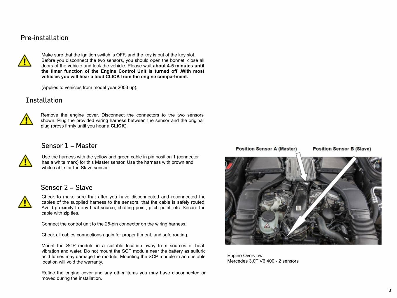
Engine Overview Mercedes 3.0T V6 400 - 2 sensors
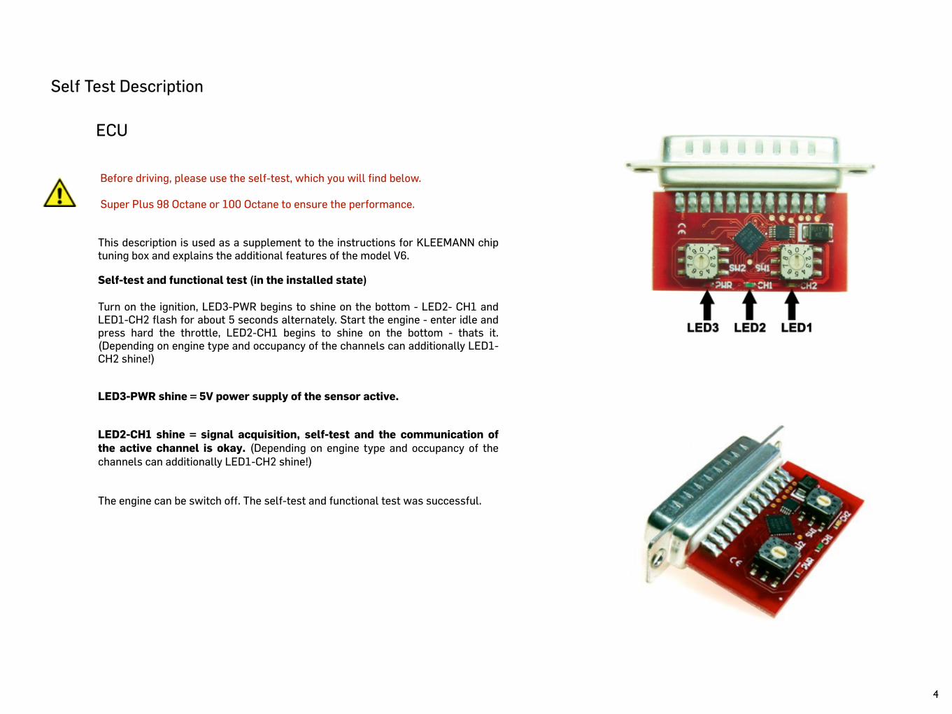
Self Test Description
This description is used as a supplement to the instructions for KLEEMANN chip tuning box and explains the additional features of the model V6. !Self-test and functional test (in the installed state) !Turn on the ignition, LED3-PWR begins to shine on the bottom - LED2- CH1 and LED1-CH2 flash for about 5 seconds alternately. Start the engine - enter idle and press hard the throttle, LED2-CH1 begins to shine on the bottom - thats it. (Depending on engine type and occupancy of the channels can additionally LED1-CH2 shine!) !!LED3-PWR shine = 5V power supply of the sensor active. !!LED2-CH1 shine = signal acquisition, self-test and the communication of the active channel is okay. (Depending on engine type and occupancy of the channels can additionally LED1-CH2 shine!) !!The engine can be switch off. The self-test and functional test was successful.
ECU
Before driving, please use the self-test, which you will find below. !Super Plus 98 Octane or 100 Octane to ensure the performance.
4