Embed Size (px)
Citation preview
DESIGN AND DEVELOPMENT A SMALL STIRLING ENGINE
NURUL HUDA BINTI BASO
A report submitted in fulfillment of the requirements
for the award of Bachelor of Mechanical Engineering.
Faculty of Mechanical Engineering
UNIVERSITI MALAYSIA PAHANG
June 2012
vii
ABSTRACT
A stirling engine is a heat engine operating by cyclic compression and expansion
of air or other gas, the working fluid, at different temperature levels such as net
conversion of heat energy to mechanical work. The Stirling engine was noted for its high
efficiency compared to steam engines, quiet operation, and the ease with which it can
use almost any heat source. The purpose of the project, are to design and fabricate the
stirling engine. In this project, all the components were fabricating using milling
machine, cutter, lathe machine, and CNC machine. Besides that, all the components will
be assembled and the performance of stirling engine will be analyzed. Schmidt Analysis
of Ideal Isothermal equation were use to find the performance of stirling engine in watt.
The fin at cold cylinder will be analyzed using fins heat transfer equation.
viii
ABSTRAK
Enjin stirling adalah kitaran operasi enjin oleh haba mampatan dan
pengembangan oleh udara atau gas pada tahap suhu tenaga bersih kepada kerja mekanik.
Enjin Stirling terkenal dengan kecekapan yang tinggi berbanding dengan enjin wap,
operasi yang senyap dan mudah yang boleh menggunakan hampir mana-mana sumber
haba. Tujuan projek ini, adalah untuk mereka bentuk dan memasang siap enjin stirling.
Dalam projek ini, semua komponen telah direkabentuk menggunakan mesin milling,
mesin larik dan mesin CNC. Selain itu, semua komponen akan dipasang dan prestasi
enjin stirling akan dianalisis. Analisis Schmidt persamaan Isothermal telah digunakan
untuk mencari prestasi stirling enjin dalam watt. Sirip pada silinder sejuk akan dianalisis
dengan menggunakan sirip persamaan pemindahan haba.
ix
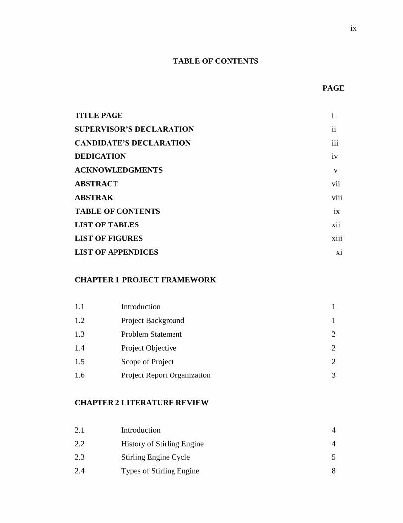
TABLE OF CONTENTS
PAGE
TITLE PAGE i
SUPERVISOR’S DECLARATION ii
CANDIDATE’S DECLARATION iii
DEDICATION iv
ACKNOWLEDGMENTS v
ABSTRACT vii
ABSTRAK viii
TABLE OF CONTENTS ix
LIST OF TABLES xii
LIST OF FIGURES xiii
LIST OF APPENDICES xi
CHAPTER 1 PROJECT FRAMEWORK
1.1 Introduction 1
1.2 Project Background 1
1.3 Problem Statement 2
1.4 Project Objective 2
1.5 Scope of Project 2
1.6 Project Report Organization 3
CHAPTER 2 LITERATURE REVIEW
2.1 Introduction 4
2.2 History of Stirling Engine 4
2.3 Stirling Engine Cycle 5
2.4 Types of Stirling Engine 8
x
2.4.1 The Alpha Type 8
2.4.2 The Beta Type 11
2.4.3 The Gamma Type 13
2.5 An Overview of Flywheel 14
2.6 Flywheel Design Consideration 15
2.7 Flywheel Design Analysis 16
2.8 Finite Element Analysis Modeling 16
2.9 Design Requirements for Stirling Engine 19
CHAPTER 3 METHODOLOGY
3.1 Introduction 20
3.2 Flow in the Project 21
3.2.1 Flow Chart of PSM 1 and PSM 2 22
3.2.2 Gathering the Literature Review 22
3.2.3 Design 23
3.2.4 Decision 23
3.2.5 3D Modeling 24
3.2.6 Material Selection 24
3.2.7 Fabrication 25
3.3 Significant in the Methodology 25
3.3.1 Design 25
3.3.2 Cylinder Component Design 26
3.3.3 Material Selection 27
3.3.4 Fabrication Part 30
3.3.5 Assembly 44
CHAPTER 4 RESULTS AND DISSCUSSION
4.1 Introduction 45
4.2 Fin Heat Transfer 46
xi
4.3 Schmidt Analysis of Ideal Isothermal Model 50
4.4 Discussion 54
CHAPTER 5 CONCLUSION AND RECOMMENDATIONS 56
5.1 Conclusion 56
5.2 Recommendations 56
REFERENCES 58
APPENDICES
A Gantt chart for PSM 1 and PSM 2 60
B Small Stirling Engine Orthographic Drawing 61

xii
LIST OF TABLES
Table No. Title Page
2.1 Comparison of FEA Results for All Cases 18
3.1 Bill of Material 28
3.2 Steps to Fabricate Flywheel 31
3.3 Steps to Fabricate Flywheel Support 32
3.4 Steps to Fabricate Stirling Base 33
3.5 Steps to Fabricate Connector-Cylinder Cold 34
3.6 Steps to Fabricate Connector-Cylinder Hot 35
3.7 Steps to Fabricate Bracket 36
3.8 Steps to Fabricate Cold Cylinder Piston 37
3.9 Steps to Fabricate Hot Cylinder Piston 38
3.10 Steps to Fabricate Cranks 40
3.11 Steps to Fabricate Hot & Cold Base 41
3.12 Steps to Fabricate Pin Hold 42
3.13 Standard Part 43
4.1 Cool Water Bath Criteria 47
4.2 Cylinder Dimension 48
4.3 Material Aluminum Cylinder 48
4.4 Calculation Summary 50
4.5 Summary Result 50
4.6 Value of Design 52
4.7 Value of Parameter 54
4.8 Comparison to Theory 55
xiii
LIST OF FIGURE
Figure No. Title Page
2.1 Ideal Stirling Cycle P-v and T-s Diagrams 6
2.2 Real Stirling Cycle P-v Diagram Approximation 6
2.3 The Alpha Type 8
2.4 The Alpha Type Expansion 8
2.5 The Alpha Type Transfer 9
2.6 The Alpha Type Contraction 9
2.7 The 2nd
Alpha Type Transfer 10
2.8 The Beta Type 11
2.9 The Beta Type Expansion 11
2.10 The Beta Type Transfer 12
2.11 The Beta Type Contraction 12
2.12 The 2nd
Beta Type Transfer 13
2.13 The Gamma Type 14
2.14 2D View of Solid Flywheel Model 16
2.15 Geometry of Flywheel 17
2.16 Equivalent Stress Distributions for Case 1-Case 6 18
3.1 Flow Chart for PSM 1 and PSM 2 22
3.2 Flywheel 31
3.3 Flywheel Support 32
3.4 Stirling Base 33
3.5 Connector – Cylinder Cold 34
3.6 Connector – Cylinder Hot 35
3.7 Bracket 36
3.8 Cold Cylinder Piston 38
3.9 Hot Cylinder Piston 39
xiv
LIST OF FIGURE
Figure No. Title Page
3.10 Cranks 40
3.11 Hot & Cold Base 41
3.12 Pin Hold 42
3.13 Piston 43
3.14 Bearing 44
3.15 Piston Rod 44
3.16 Bolt & Nut 44
4.1 Complete Assemble of Stirling Engine 46
4.2 Diagram of Cold Cylinder 47
4.3 Graf Heat Transfer Efficiency 49
1
CHAPTER 1
PROJECT FRAMEWORK
1.1 Introduction
Stirling engines are a category of engine, just like diesel engines. They are a closed-
cycle engine, which means that air or other gas such as helium is used over and over again
inside the engine. Stirling engines can be “regenerative.” This means that some of the heat
used to expand the air in one cycle can be used again to expand the air in the next cycle.
Stirling engines do this by moving the air across another material called a regenerator.
When the hot air in a Stirling engine flows over the cool regenerator, some of the heat from
the air flows into the regenerator, heating it up. This pre-cools the air before it moves to the
cold side of the engine, where it will reject more of its heat and complete the cycle.
This project starts with the basic information of stirling engine. Software
SolidWorks2011 is extensively used in order to design the 3D and orthographic drawings.
Then, all part was fabricated and assembles.
1.2 Project Background
This project begins with an overview all types of stirling engine. To design 3D and
orthographic drawings of stirling engine software SolidWorks 2011 is being used. From
that, all components of stirling engine had been shown and fabricate. To assemble all
components of stirling engine all part will fabricate and output of stirling engine will
perform.
2
1.3 Problem Statement
In the recent ‘green-energy’ movement the stirling cycle has received renewed
interest in the area of power generation, and it is the intention to help raise awareness and
promote renewable energies by demonstrating the potential of the stirling engine. Stirling
engine are known for having a high thermodynamic efficiency. Ideally, a stirling cycle
engine can be designed to approximate the theoretical carnot cycle engine.
1.4 Project Objective
The main objectives of this project are:
1. To design the stirling engine.
2. To fabricate the stirling engine.
3. To determine the performance of stirling engine.
1.5 Scope of Project
This project will focus on:
1. Gamma type stirling engine.
2. Reviewing the history, other research and study relevance to the title.
3. Design the small stirling engine.
4. Select suitable material for each components and parts.
3
5. Fabricate the small stirling engine using suitable process, concept and
suitable machine.
1.6 Project Report Organization
This project is organized into five chapters where:
1. Chapter 1 includes the project framework.
2. Chapter 2 reviews on the historical,
3. Chapter 3 presents on the methodology of the project. This chapter reviews
on the machines that were used such as Miling Machine, Cutter, Lathe
Machine, and CNC machine. Besides that, SolidWorks2011 was discussed.
4. Chapter 4 focuses on result and discussion. In this chapter the performance
and heat transfer of the stirling engine will been reviewed. All the obtaining
result or output is discussed too.
5. Chapter 5 will summarize all the obtaining results. Recommendation for
further work is also given.
4
CHAPTER 2
LITERATURE REVIEW
2.1 Introduction
This chapter provides a history of stirling engine and process flow in all its types.
Besides, an overview of flywheel design principles is also presented.
2.2 History of Stirling Engine
The Stirling engine was invented by Robert Stirling, a Scottish minister, in 1816.
The early Stirling engine had a history of good service and long life (up to 20 years). It was
used as a relatively low-power water-pumping engine from the middle of the nineteenth
century to about 1920, when the internal combustion engine and the electric motor replaced
it. The hot-air engine was known for its ease of operation and its ability to use any burnable
material as fuel. It’s safe, quiet, moderately efficient operation and its durability and low
maintenance requirements. It was very large for its small power output with a high
purchase cost. Nevertheless, its low operating cost usually justified choosing it over the
steam engine the only alternative at the time which burned much more fuel for the same
power and demanded constant attention to avoid dangerous explosions or other failures.
This situation changed in 1980, when the U.S. Agency for International
Development (USAID) funded the development of a simple Stirling engine specifically
intended for manufacture and use in developing countries. The engine was designed, built,
tested, and delivered to Bangladesh, and copies of it were built and put into operation there.
5
This demonstrated the Possibility of the engine's manufacture in simple machine shops of
the type found in many regions of Africa, Asia, and Latin America.
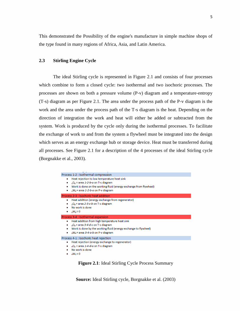
2.3 Stirling Engine Cycle
The ideal Stirling cycle is represented in Figure 2.1 and consists of four processes
which combine to form a closed cycle: two isothermal and two isochoric processes. The
processes are shown on both a pressure volume (P‐v) diagram and a temperature‐entropy
(T‐s) diagram as per Figure 2.1. The area under the process path of the P‐v diagram is the
work and the area under the process path of the T‐s diagram is the heat. Depending on the
direction of integration the work and heat will either be added or subtracted from the
system. Work is produced by the cycle only during the isothermal processes. To facilitate
the exchange of work to and from the system a flywheel must be integrated into the design
which serves as an energy exchange hub or storage device. Heat must be transferred during
all processes. See Figure 2.1 for a description of the 4 processes of the ideal Stirling cycle
(Borgnakke et al., 2003).
Figure 2.1: Ideal Stirling Cycle Process Summary
Source: Ideal Stirling cycle, Borgnakke et al. (2003)
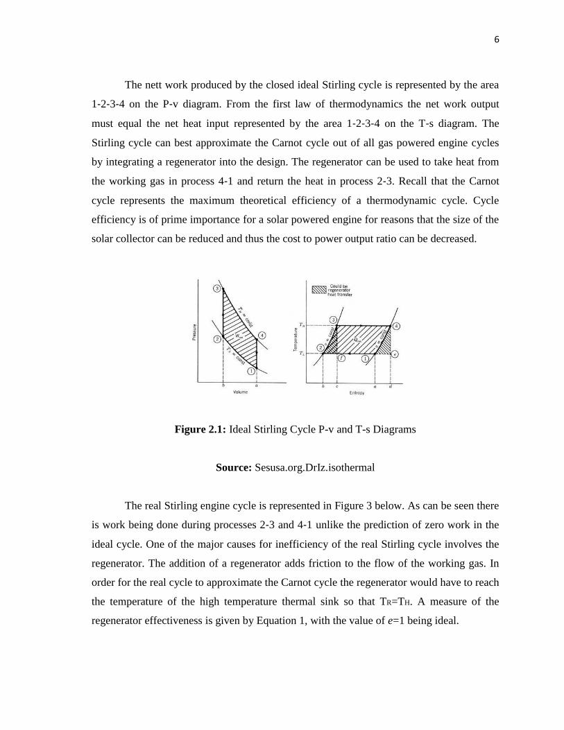
6
The nett work produced by the closed ideal Stirling cycle is represented by the area
1‐2‐3‐4 on the P‐v diagram. From the first law of thermodynamics the net work output
must equal the net heat input represented by the area 1‐2‐3‐4 on the T‐s diagram. The
Stirling cycle can best approximate the Carnot cycle out of all gas powered engine cycles
by integrating a regenerator into the design. The regenerator can be used to take heat from
the working gas in process 4‐1 and return the heat in process 2‐3. Recall that the Carnot
cycle represents the maximum theoretical efficiency of a thermodynamic cycle. Cycle
efficiency is of prime importance for a solar powered engine for reasons that the size of the
solar collector can be reduced and thus the cost to power output ratio can be decreased.
Figure 2.1: Ideal Stirling Cycle P-v and T-s Diagrams
Source: Sesusa.org.DrIz.isothermal
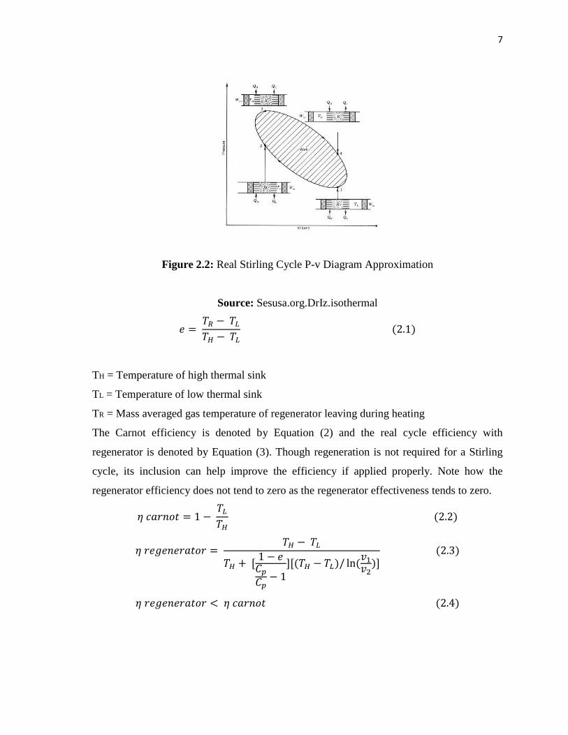
The real Stirling engine cycle is represented in Figure 3 below. As can be seen there
is work being done during processes 2‐3 and 4‐1 unlike the prediction of zero work in the
ideal cycle. One of the major causes for inefficiency of the real Stirling cycle involves the
regenerator. The addition of a regenerator adds friction to the flow of the working gas. In
order for the real cycle to approximate the Carnot cycle the regenerator would have to reach
the temperature of the high temperature thermal sink so that TR=TH. A measure of the
regenerator effectiveness is given by Equation 1, with the value of e=1 being ideal.
7
Figure 2.2: Real Stirling Cycle P-v Diagram Approximation
Source: Sesusa.org.DrIz.isothermal
TH = Temperature of high thermal sink
TL = Temperature of low thermal sink
TR = Mass averaged gas temperature of regenerator leaving during heating
The Carnot efficiency is denoted by Equation (2) and the real cycle efficiency with
regenerator is denoted by Equation (3). Though regeneration is not required for a Stirling
cycle, its inclusion can help improve the efficiency if applied properly. Note how the
regenerator efficiency does not tend to zero as the regenerator effectiveness tends to zero.
8
2.4 Types of Stirling Engine
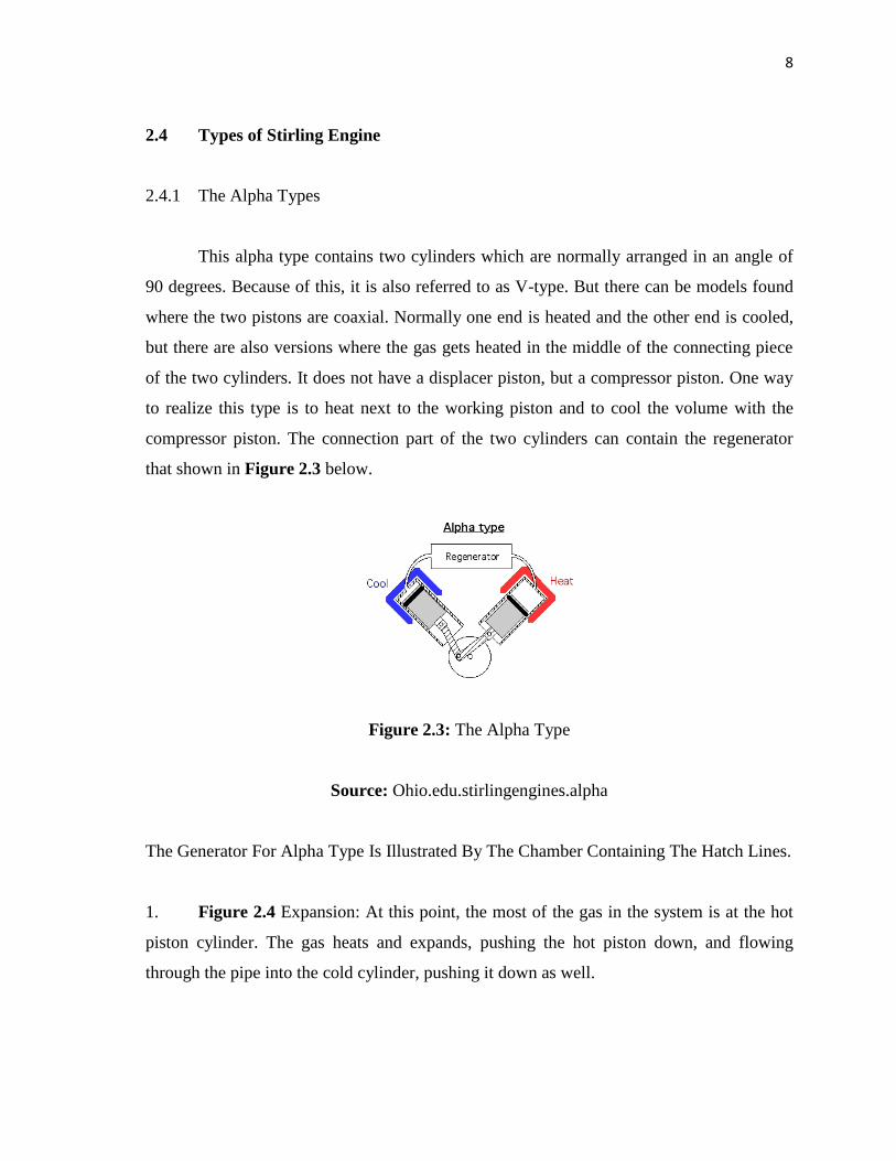
2.4.1 The Alpha Types
This alpha type contains two cylinders which are normally arranged in an angle of
90 degrees. Because of this, it is also referred to as V-type. But there can be models found
where the two pistons are coaxial. Normally one end is heated and the other end is cooled,
but there are also versions where the gas gets heated in the middle of the connecting piece
of the two cylinders. It does not have a displacer piston, but a compressor piston. One way
to realize this type is to heat next to the working piston and to cool the volume with the
compressor piston. The connection part of the two cylinders can contain the regenerator
that shown in Figure 2.3 below.
Figure 2.3: The Alpha Type
Source: Ohio.edu.stirlingengines.alpha
The Generator For Alpha Type Is Illustrated By The Chamber Containing The Hatch Lines.
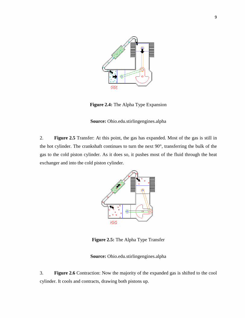
1. Figure 2.4 Expansion: At this point, the most of the gas in the system is at the hot
piston cylinder. The gas heats and expands, pushing the hot piston down, and flowing
through the pipe into the cold cylinder, pushing it down as well.
9
Figure 2.4: The Alpha Type Expansion
Source: Ohio.edu.stirlingengines.alpha
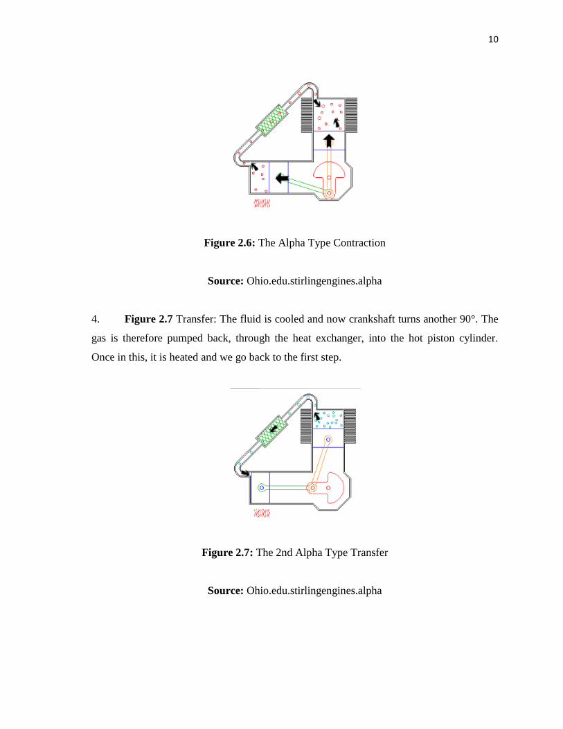
2. Figure 2.5 Transfer: At this point, the gas has expanded. Most of the gas is still in
the hot cylinder. The crankshaft continues to turn the next 90°, transferring the bulk of the
gas to the cold piston cylinder. As it does so, it pushes most of the fluid through the heat
exchanger and into the cold piston cylinder.
Figure 2.5: The Alpha Type Transfer
Source: Ohio.edu.stirlingengines.alpha
3. Figure 2.6 Contraction: Now the majority of the expanded gas is shifted to the cool
cylinder. It cools and contracts, drawing both pistons up.
10
Figure 2.6: The Alpha Type Contraction
Source: Ohio.edu.stirlingengines.alpha
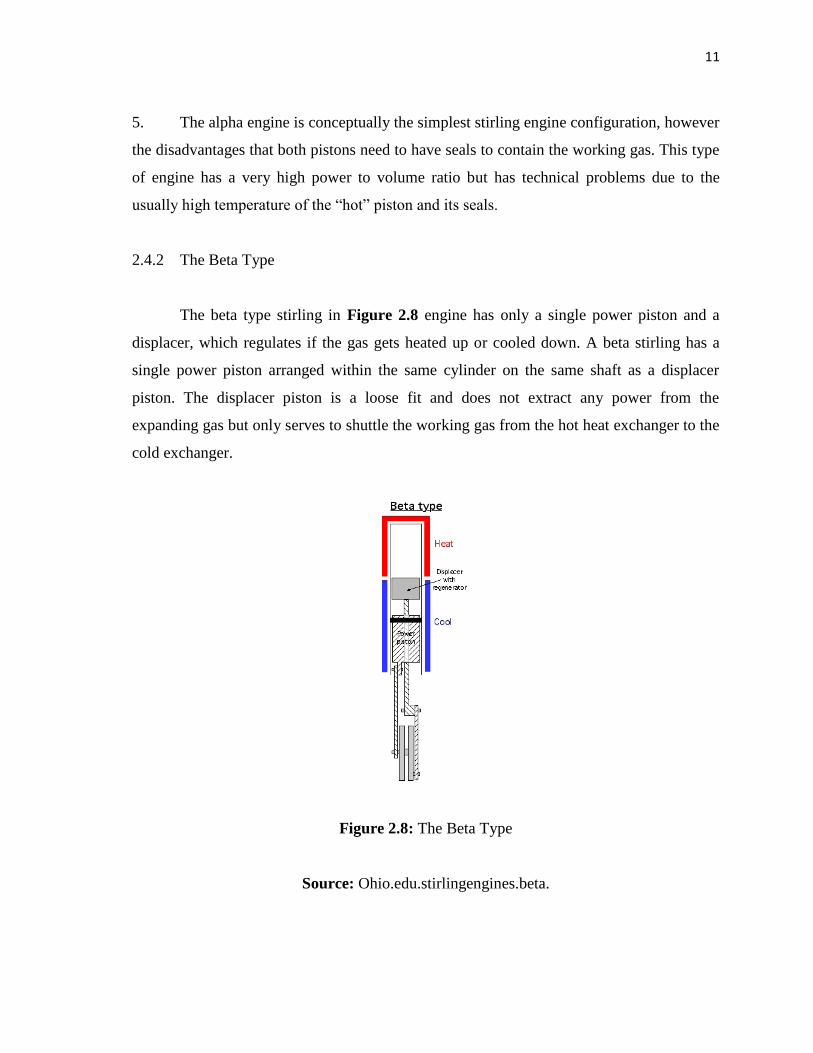
4. Figure 2.7 Transfer: The fluid is cooled and now crankshaft turns another 90°. The
gas is therefore pumped back, through the heat exchanger, into the hot piston cylinder.
Once in this, it is heated and we go back to the first step.
Figure 2.7: The 2nd Alpha Type Transfer
Source: Ohio.edu.stirlingengines.alpha
11
5. The alpha engine is conceptually the simplest stirling engine configuration, however
the disadvantages that both pistons need to have seals to contain the working gas. This type
of engine has a very high power to volume ratio but has technical problems due to the
usually high temperature of the “hot” piston and its seals.
2.4.2 The Beta Type
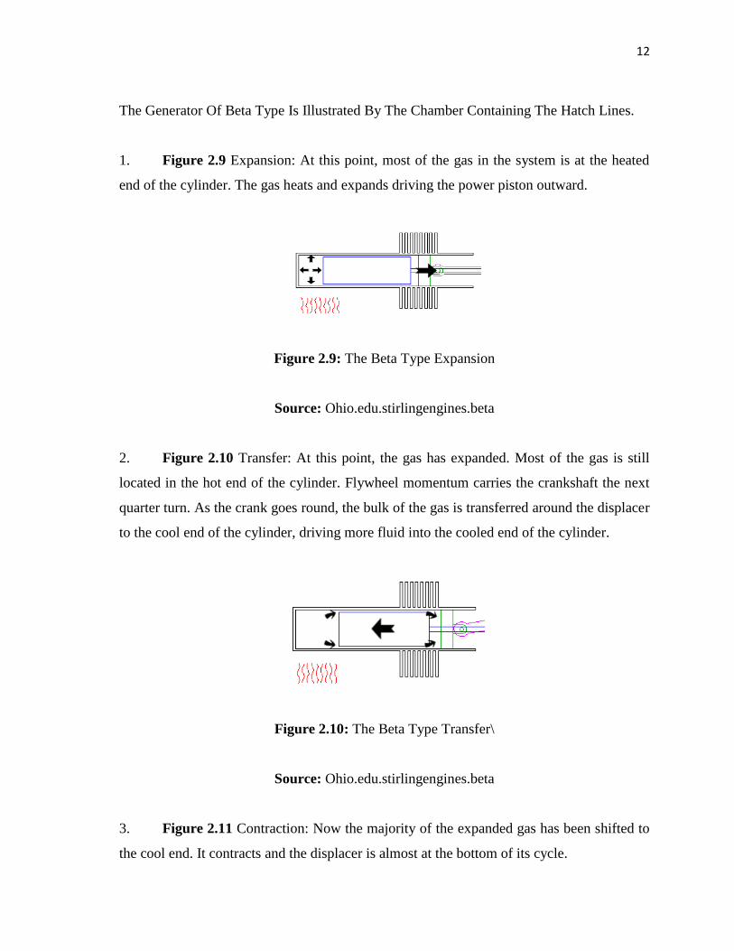
The beta type stirling in Figure 2.8 engine has only a single power piston and a
displacer, which regulates if the gas gets heated up or cooled down. A beta stirling has a
single power piston arranged within the same cylinder on the same shaft as a displacer
piston. The displacer piston is a loose fit and does not extract any power from the
expanding gas but only serves to shuttle the working gas from the hot heat exchanger to the
cold exchanger.
Figure 2.8: The Beta Type
Source: Ohio.edu.stirlingengines.beta.
12
The Generator Of Beta Type Is Illustrated By The Chamber Containing The Hatch Lines.
1. Figure 2.9 Expansion: At this point, most of the gas in the system is at the heated
end of the cylinder. The gas heats and expands driving the power piston outward.
Figure 2.9: The Beta Type Expansion
Source: Ohio.edu.stirlingengines.beta
2. Figure 2.10 Transfer: At this point, the gas has expanded. Most of the gas is still
located in the hot end of the cylinder. Flywheel momentum carries the crankshaft the next
quarter turn. As the crank goes round, the bulk of the gas is transferred around the displacer
to the cool end of the cylinder, driving more fluid into the cooled end of the cylinder.
Figure 2.10: The Beta Type Transfer\
Source: Ohio.edu.stirlingengines.beta
3. Figure 2.11 Contraction: Now the majority of the expanded gas has been shifted to
the cool end. It contracts and the displacer is almost at the bottom of its cycle.
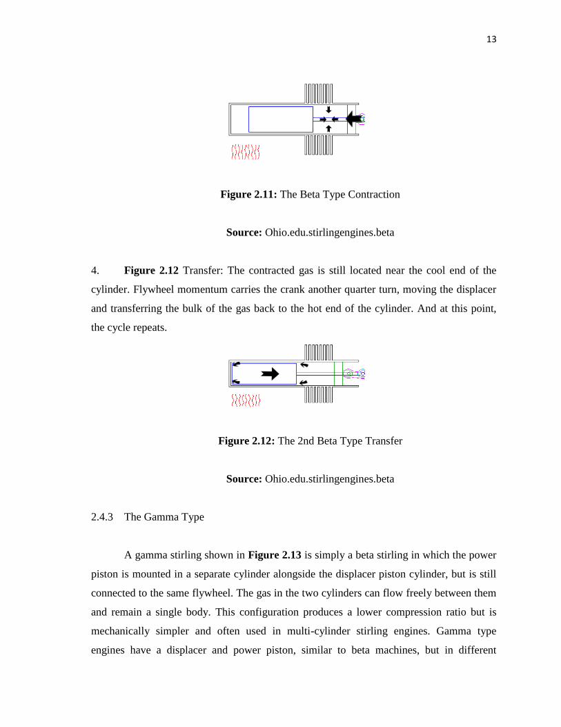
13
Figure 2.11: The Beta Type Contraction
Source: Ohio.edu.stirlingengines.beta
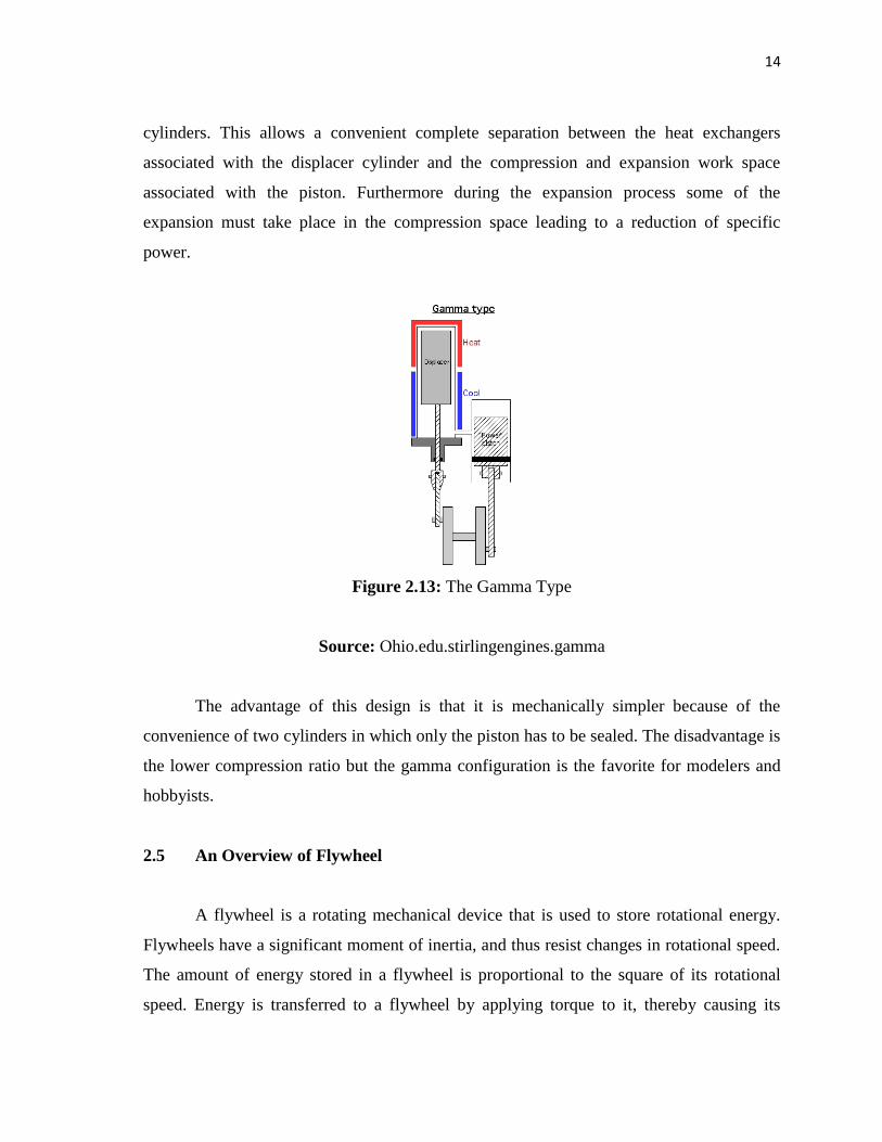
4. Figure 2.12 Transfer: The contracted gas is still located near the cool end of the
cylinder. Flywheel momentum carries the crank another quarter turn, moving the displacer
and transferring the bulk of the gas back to the hot end of the cylinder. And at this point,
the cycle repeats.
Figure 2.12: The 2nd Beta Type Transfer
Source: Ohio.edu.stirlingengines.beta
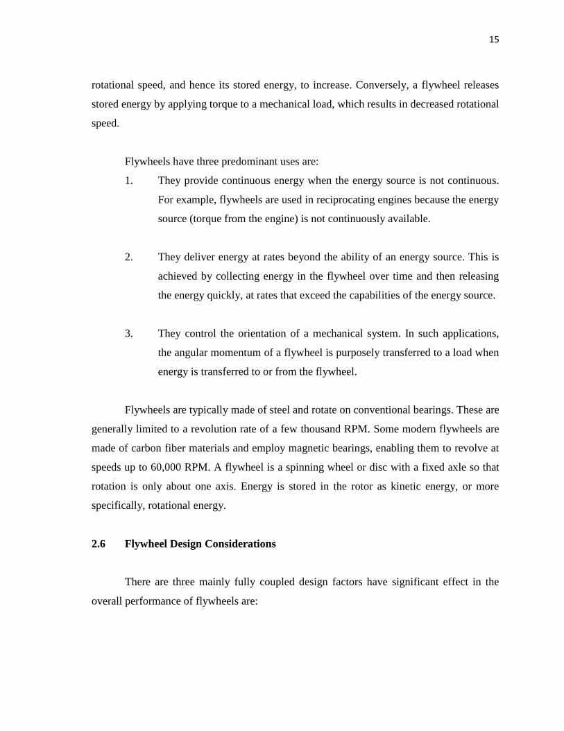
2.4.3 The Gamma Type
A gamma stirling shown in Figure 2.13 is simply a beta stirling in which the power
piston is mounted in a separate cylinder alongside the displacer piston cylinder, but is still
connected to the same flywheel. The gas in the two cylinders can flow freely between them
and remain a single body. This configuration produces a lower compression ratio but is
mechanically simpler and often used in multi-cylinder stirling engines. Gamma type
engines have a displacer and power piston, similar to beta machines, but in different
14
cylinders. This allows a convenient complete separation between the heat exchangers
associated with the displacer cylinder and the compression and expansion work space
associated with the piston. Furthermore during the expansion process some of the
expansion must take place in the compression space leading to a reduction of specific
power.
Figure 2.13: The Gamma Type
Source: Ohio.edu.stirlingengines.gamma
The advantage of this design is that it is mechanically simpler because of the
convenience of two cylinders in which only the piston has to be sealed. The disadvantage is
the lower compression ratio but the gamma configuration is the favorite for modelers and
hobbyists.
2.5 An Overview of Flywheel
A flywheel is a rotating mechanical device that is used to store rotational energy.
Flywheels have a significant moment of inertia, and thus resist changes in rotational speed.
The amount of energy stored in a flywheel is proportional to the square of its rotational
speed. Energy is transferred to a flywheel by applying torque to it, thereby causing its
15
rotational speed, and hence its stored energy, to increase. Conversely, a flywheel releases
stored energy by applying torque to a mechanical load, which results in decreased rotational
speed.
Flywheels have three predominant uses are:
1. They provide continuous energy when the energy source is not continuous.
For example, flywheels are used in reciprocating engines because the energy
source (torque from the engine) is not continuously available.
2. They deliver energy at rates beyond the ability of an energy source. This is
achieved by collecting energy in the flywheel over time and then releasing
the energy quickly, at rates that exceed the capabilities of the energy source.
3. They control the orientation of a mechanical system. In such applications,
the angular momentum of a flywheel is purposely transferred to a load when
energy is transferred to or from the flywheel.
Flywheels are typically made of steel and rotate on conventional bearings. These are
generally limited to a revolution rate of a few thousand RPM. Some modern flywheels are
made of carbon fiber materials and employ magnetic bearings, enabling them to revolve at
speeds up to 60,000 RPM. A flywheel is a spinning wheel or disc with a fixed axle so that
rotation is only about one axis. Energy is stored in the rotor as kinetic energy, or more
specifically, rotational energy.
2.6 Flywheel Design Considerations
There are three mainly fully coupled design factors have significant effect in the
overall performance of flywheels are: