Embed Size (px)
Citation preview

FLYWHEEL
K C Karthik2nd sem, M.Tech (A.E)
FlywheelA rotating mechanical device that is used to store rotational
energy.
A flywheel is used in machines , serves as a reservoir which stores energy during the period where the supply of energy is more than the requirement.
Conversely, a flywheel releases stored energy by applying torque to a mechanical load, thereby decreasing the flywheel's rotational speed.
FlywheelIn other words it can be defined as “it stores energy during
power stroke and delivers during idle strokes”.
A little considerations will show that when the flywheel absorbs energy, its speed increases and when it releases, the speed decreases. Hence a flywheel does not maintain a constant speed, it simply reduces the fluctuation of speed.
The flywheel’s position is between the engine and clutch patch to the starter.
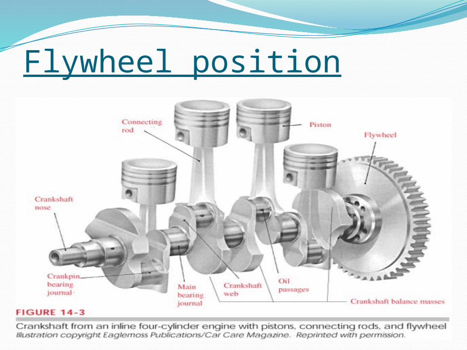
Flywheel position
A Flywheel is used to maintain constant angular velocity of the crankshaft in a reciprocating engine. In this case, the flywheel—which is mounted on the crankshaft—stores energy when torque is exerted on it by a firing piston and it releases energy to its mechanical loads when no piston is exerting torque on it.
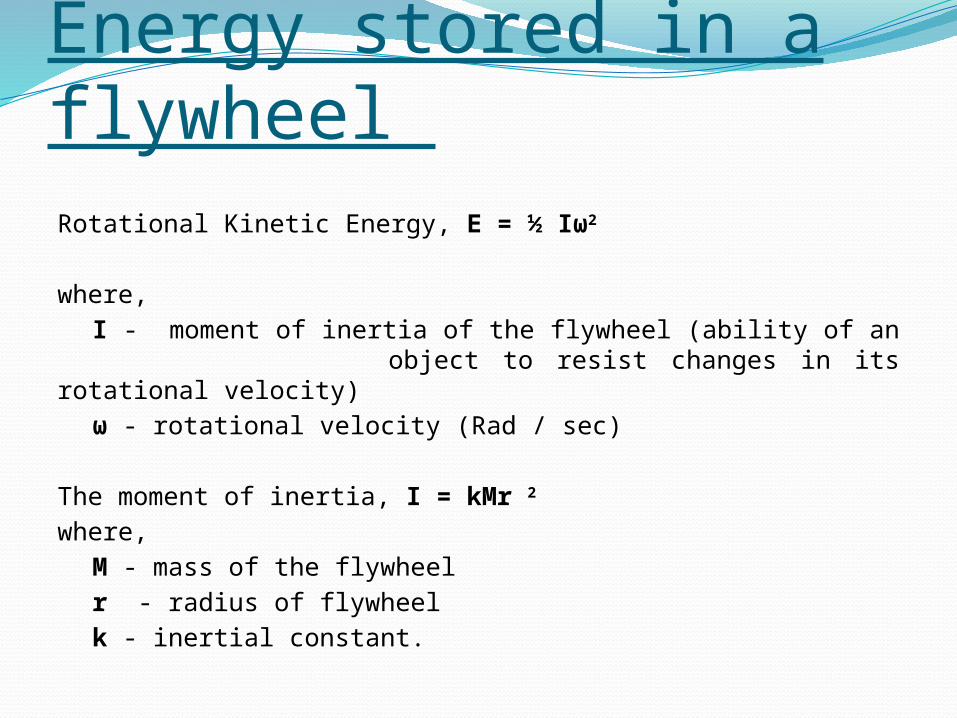
Energy stored in a flywheel Rotational Kinetic Energy, E = ½ Iω2
where,
I - moment of inertia of the flywheel (ability of an object to resist changes in its rotational velocity)
ω - rotational velocity (Rad / sec)
The moment of inertia, I = kMr 2
where,
M - mass of the flywheel
r - radius of flywheel
k - inertial constant.
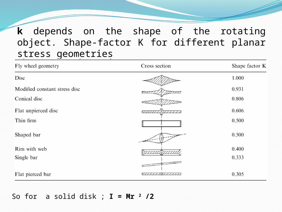
k depends on the shape of the rotating object. Shape-factor K for different planar stress geometries
So for a solid disk ; I = Mr 2 /2
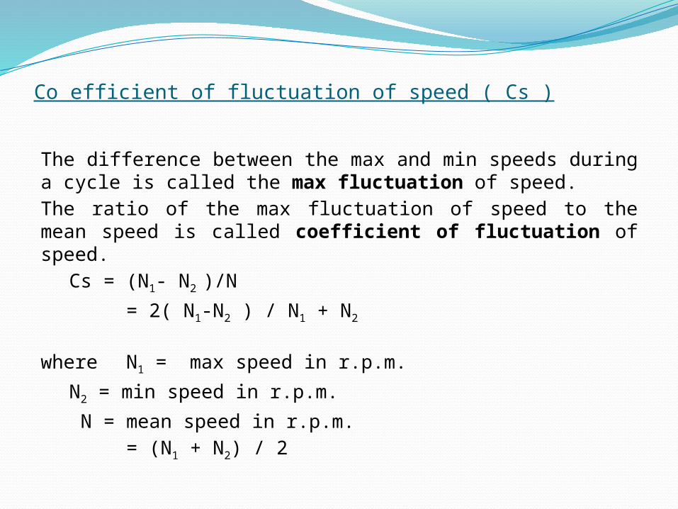
Co efficient of fluctuation of speed ( Cs )
The difference between the max and min speeds during a cycle is called the max fluctuation of speed.
The ratio of the max fluctuation of speed to the mean speed is called coefficient of fluctuation of speed.
Cs = (N1- N2 )/N
= 2( N1-N2 ) / N1 + N2
where N1 = max speed in r.p.m.
N2 = min speed in r.p.m.
N = mean speed in r.p.m.
= (N1 + N2) / 2
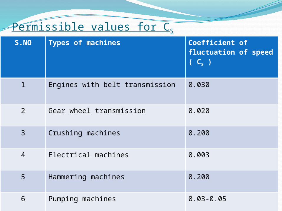
Permissible values for CS
S.NO Types of machines Coefficient of fluctuation of speed ( CS )
1 Engines with belt transmission 0.030
2 Gear wheel transmission 0.020
3 Crushing machines 0.200
4 Electrical machines 0.003
5 Hammering machines 0.200
6 Pumping machines 0.03-0.05
7 Machine tools 0.030
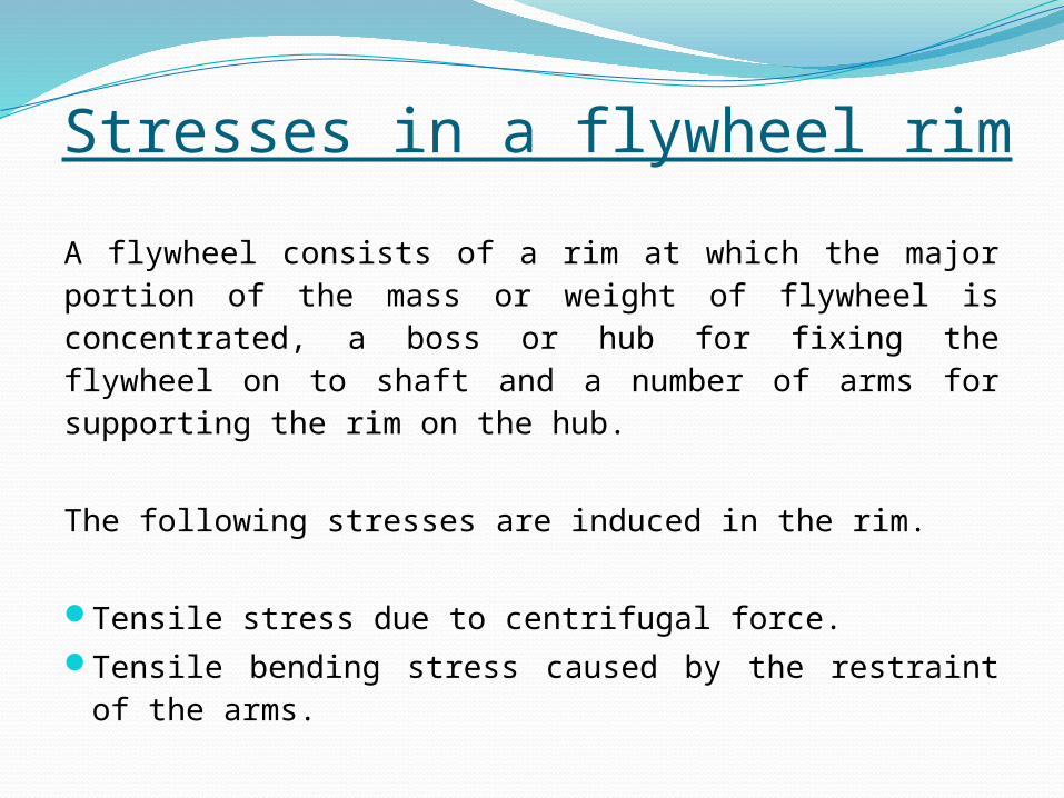
Stresses in a flywheel rim
A flywheel consists of a rim at which the major portion of the mass or weight of flywheel is concentrated, a boss or hub for fixing the flywheel on to shaft and a number of arms for supporting the rim on the hub.
The following stresses are induced in the rim.
Tensile stress due to centrifugal force.Tensile bending stress caused by the restraint of the arms.
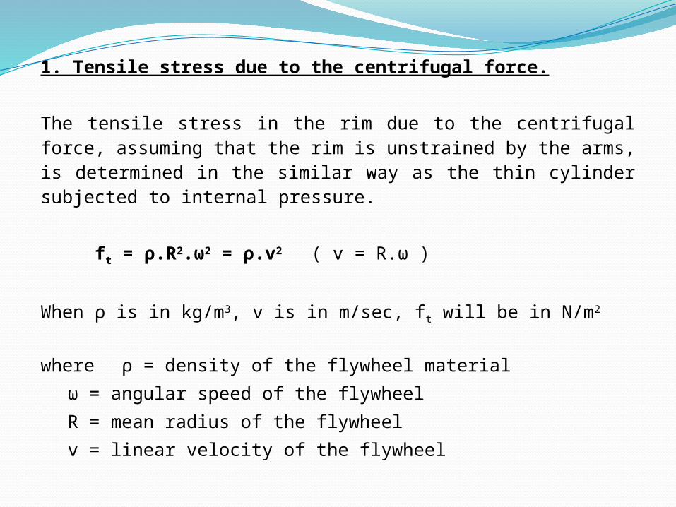
1. Tensile stress due to the centrifugal force.
The tensile stress in the rim due to the centrifugal force, assuming that the rim is unstrained by the arms, is determined in the similar way as the thin cylinder subjected to internal pressure.
ft = ρ.R2.ω2 = ρ.v2 ( v = R.ω )
When ρ is in kg/m3, v is in m/sec, ft will be in N/m2
where ρ = density of the flywheel material
ω = angular speed of the flywheel
R = mean radius of the flywheel
v = linear velocity of the flywheel
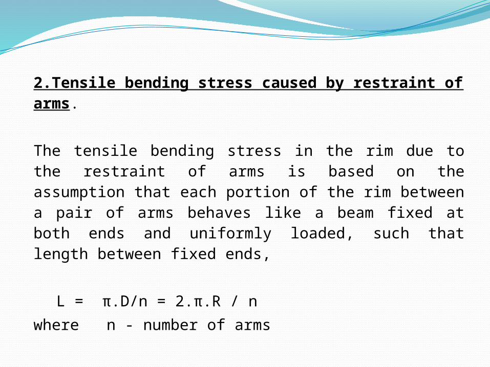
2.Tensile bending stress caused by restraint of arms.
The tensile bending stress in the rim due to the restraint of arms is based on the assumption that each portion of the rim between a pair of arms behaves like a beam fixed at both ends and uniformly loaded, such that length between fixed ends,
L = π.D/n = 2.π.R / n
where n - number of arms

The max bending moment, M = w.l2 /12 = b.t.ρ.ω2.R/12(2.π.R/n)
Section modulus, Z = 1/6 (b.t2)
So bending stress fb = M/Z = b.t.ρ.ω2.R/12 (2.π.R/n) * 6 / (b.t2)
Total stress in the rim f = ft + fb
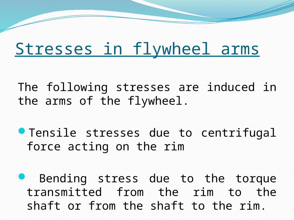
Stresses in flywheel arms
The following stresses are induced in the arms of the flywheel.
Tensile stresses due to centrifugal force acting on the rim
Bending stress due to the torque transmitted from the rim to the shaft or from the shaft to the rim.
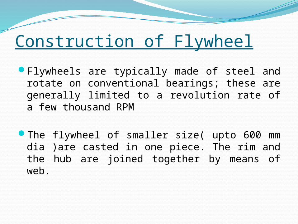
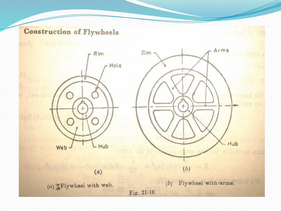
Construction of Flywheel
Flywheels are typically made of steel and rotate on conventional bearings; these are generally limited to a revolution rate of a few thousand RPM
The flywheel of smaller size( upto 600 mm dia )are casted in one piece. The rim and the hub are joined together by means of web.
Construction
If flywheel is of larger size (upto 2-5 meters diameter ), then it is made of arms.
The number of arms depends upon the size of the flywheel and its speed of rotation. But the flywheels above 2-5 meters are usually casted in two pieces. Such a flywheel is known as “ split flywheel “.
A split flywheel has the advantage of relieving the shrinkage stresses in the arms due to unequal rates of cooling of casting.
ApplicationsProviding continuous energy when the energy source is
discontinuous. For example, flywheels are used in reciprocating engines because the energy source, torque from the engine, is intermittent.
Delivering energy at rates beyond the ability of a continuous energy source. This is achieved by collecting energy in the flywheel over time and then releasing the energy quickly, at rates that exceed the abilities of the energy source.
Dynamic balancing of rotating elements.
Energy storage in small scale electricity generator sets

Other Applications
Advance and Modern Flywheel
Flywheels have also been proposed as a power booster for electric vehicles. Speeds of 100,000 rpm have been used to achieve very high power densities.
Modern high energy flywheels use composite rotors made with carbon-fibre materials. The rotors have a very high strength-to-density ratio, and rotate at speeds up to 100,000 rpm. in a vacuum chamber to minimize aerodynamic losses.

Benefits in Aerospace
Flywheels are preferred over conventional batteries in many aerospace applications because of the following benefits:
5 to 10+ times greater specific energyLower mass / kW outputLong life. Unaffected by number of charge / discharge
cycles85-95% round trip efficiencyFewer regulators / controls neededGreater peak load capabilityReduced maintenance / life cycle costs

DisadvantagesThere are safety concerns associated with flywheels due
to their high speed rotor and the possibility of it breaking loose & releasing all of it's energy in an uncontrolled manner.
Its Bulkier, adds more weight to the vehicle.
Conclusion
Recent advances in the mechanical properties of composites has regained the interest in using the inertia of a spinning wheel to store energy.
Carbon-composite flywheel batteries have recently been manufactured and are proving to be viable in real-world tests on mainstream cars. Additionally, their disposal is more eco-friendly.