Embed Size (px)
Citation preview
CONTACT
Main Office
Northern and Yorke NRM Board
PO Box 175
41-49 Eyre Road
Crystal Brook SA 5523
Ph: (08) 8636 2361
Fx: (08) 8636 2371
www.nynrm.sa.gov.au
June 2011
NRM Plan
Government of South Australia
Northern and Yorke NaturalResources Management Board
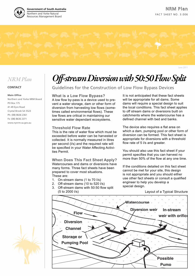
Off-stream Diversion with 50:50 Flow Split
What is a Low Flow Bypass?A low flow by-pass is a device used to pre-vent a water storage, dam or other form of diversion from harvesting low flows (some-times called environmental flows). These low flows are critical in maintaining our sensitive water dependant ecosystems.
Threshold Flow RateThis is the rate of water flow which must be exceeded before water can be harvested or collected. It is normally measured in litres per second (l/s) and the required rate will be specified in your Water Affecting Activi-ties Permit.
When Does This Fact Sheet Apply?Watercourses and dams or diversions have many forms. Three fact sheets have been prepared to cover most situations. These are:1. On-stream dams (1 to 70 l/s)2. Off-stream dams (10 to 520 l/s)3. Off-stream dams with 50:50 flow split
(5 to 2000 l/s)
It is not anticipated that these fact sheets will be appropriate for all dams. Some dams will require a special design to suit the local conditions. This fact sheet applies to off stream dams or diversions built on catchments where the watercourse has a defined channel with bed and banks.
The device also requires a flat area on which a dam, pumping pool or other form of diversion can be formed. This fact sheet is appropriate for diversions with a threshold flow rate of 5 l/s and greater.
You should also use this fact sheet if your permit specifies that you can harvest no more than 50% of the flow at any one time.
If the conditions detailed on this fact sheet cannot be met for your site, this design is not appropriate and you should either use other fact sheets or consult a qualified engineer to help you develop a special design.
FACT SHEET NO. 3 .006
Guidelines for the Construction of Low Flow Bypass Devices
In-stream Flow
Diversion
Diversion weir
Watercourse
Storage or
Possible Pump
Channel
Pumping Pool
weir with orifice
Layout of a Typical Structure
Government of South Australia
Northern and Yorke NaturalResources Management Board
Government of South Australia
Northern and Yorke NaturalResources Management Board
Government of South Australia
Northern and Yorke NaturalResources Management Board
Government of South Australia
Northern and Yorke NaturalResources Management Board
How Does The Device Work?Water is diverted from the watercourse using weirs. Two weirs are used to control flow; an in-stream weir and a diversion weir. The size, shape and difference in crest level of the weirs and notches govern the threshold at which water is diverted and also the proportion of water diverted. During low flows water passes over a notch in the in-stream weir but not over the diversion weir.
As flow rates increase the water level behind the in-stream weir increases. At flows above the threshold flow rate the water level rises above the crest level of the diversion weir and water is diverted.
Design and ConstructionThe weirs can be constructed from reinforced concrete or durable hardwood timber. Timber structures may be built by skilled handy-people whilst concrete structures must be built by an experienced builder or civil works contractor.
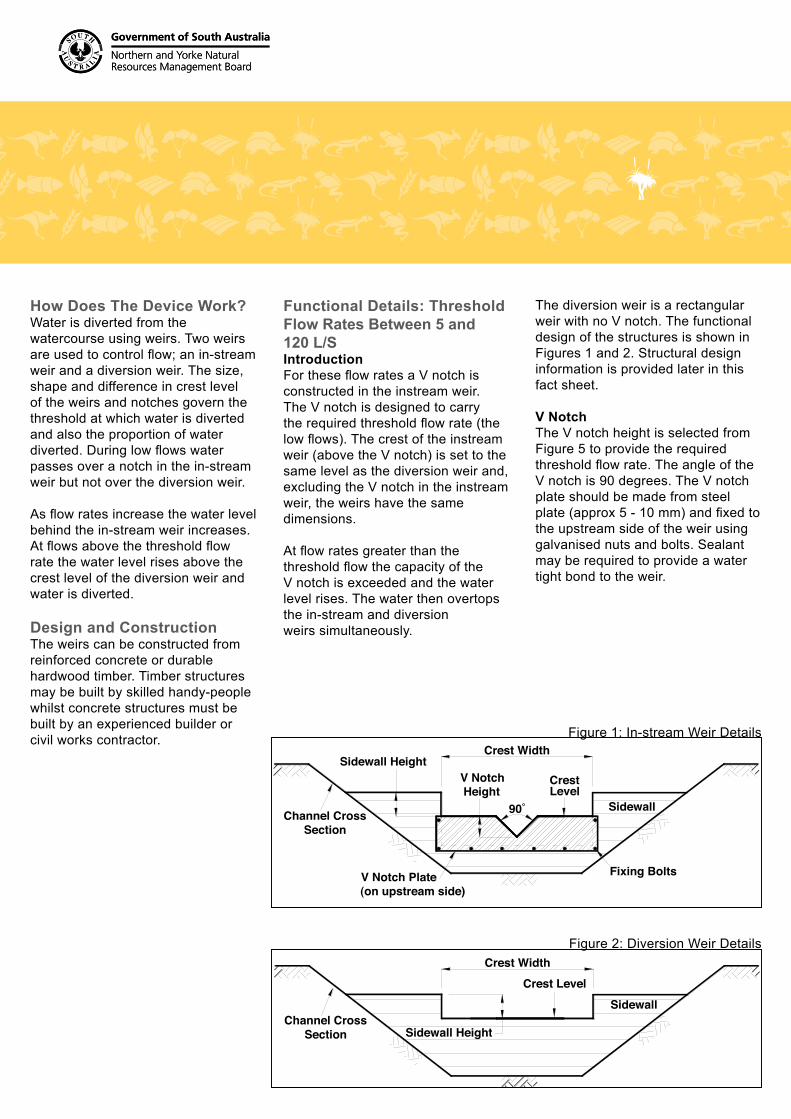
Functional Details: Threshold Flow Rates Between 5 and 120 L/SIntroductionFor these flow rates a V notch is constructed in the instream weir. The V notch is designed to carry the required threshold flow rate (the low flows). The crest of the instream weir (above the V notch) is set to the same level as the diversion weir and, excluding the V notch in the instream weir, the weirs have the same dimensions.
At flow rates greater than the threshold flow the capacity of the V notch is exceeded and the water level rises. The water then overtops the in-stream and diversion weirs simultaneously.
The diversion weir is a rectangular weir with no V notch. The functional design of the structures is shown in Figures 1 and 2. Structural design information is provided later in this fact sheet.
V NotchThe V notch height is selected from Figure 5 to provide the required threshold flow rate. The angle of theV notch is 90 degrees. The V notch plate should be made from steel plate (approx 5 - 10 mm) and fixed to the upstream side of the weir using galvanised nuts and bolts. Sealant may be required to provide a water tight bond to the weir.
90˚
CrestLevel
Crest Width
V Notch Plate(on upstream side)
Fixing Bolts
Channel CrossSection
Sidewall HeightV NotchHeight
Sidewall
Sidewall
Crest Width
Crest Level
Sidewall HeightChannel Cross
Section
Figure 1: In-stream Weir Details
Figure 2: Diversion Weir Details
Government of South Australia
Northern and Yorke NaturalResources Management Board
Government of South Australia
Northern and Yorke NaturalResources Management Board
Government of South Australia
Northern and Yorke NaturalResources Management Board
Government of South Australia
Northern and Yorke NaturalResources Management Board
Functional Details: Threshold Flow Rates Above 120 L/SIntroductionFor these higher flow rates the V notch in the in-stream weir is replaced with a rectangular notch. The rectangular notch is designed to carry the required threshold flow rate (the low flows). At flow rates greater than the threshold flow the capacity of the notch is exceeded and the water level rises. The water then overtops the in-stream and diversion weirs simultaneously.
The diversion weir is a rectangular weir with no notch. The crest of the in-stream weir (above the notch) is set to the same level as the diversion weir and, excluding the notch in the in stream weir, the weirs have the same dimensions.
The functional design of the structures is shown in Figures 3 and 4. Structural design information is provided later in this fact sheet.
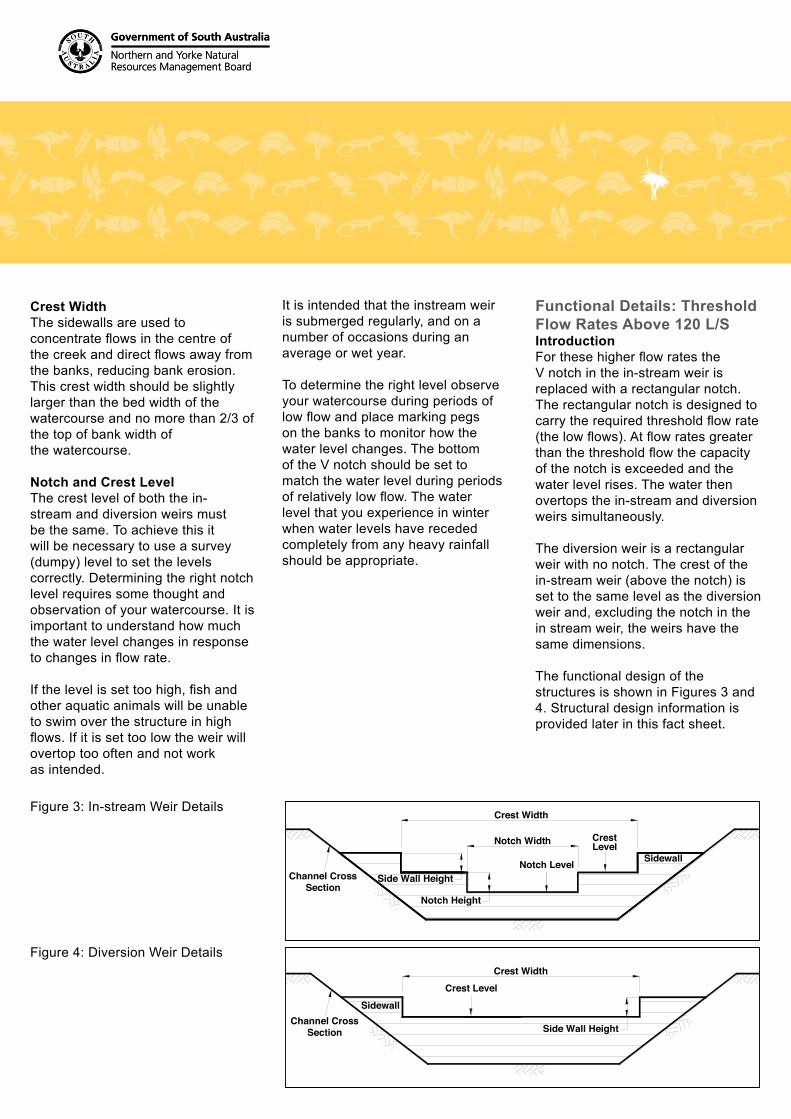
Crest WidthThe sidewalls are used to concentrate flows in the centre of the creek and direct flows away from the banks, reducing bank erosion. This crest width should be slightly larger than the bed width of the watercourse and no more than 2/3 of the top of bank width of the watercourse.
Notch and Crest LevelThe crest level of both the in-stream and diversion weirs must be the same. To achieve this it will be necessary to use a survey (dumpy) level to set the levels correctly. Determining the right notch level requires some thought and observation of your watercourse. It is important to understand how much the water level changes in response to changes in flow rate.
If the level is set too high, fish and other aquatic animals will be unable to swim over the structure in high flows. If it is set too low the weir will overtop too often and not work as intended.
It is intended that the instream weir is submerged regularly, and on a number of occasions during an average or wet year.
To determine the right level observe your watercourse during periods of low flow and place marking pegs on the banks to monitor how the water level changes. The bottom of the V notch should be set to match the water level during periods of relatively low flow. The water level that you experience in winter when water levels have receded completely from any heavy rainfall should be appropriate.
Figure 3: In-stream Weir Details
Figure 4: Diversion Weir Details
Crest Width
Side Wall Height
CrestLevel
Notch Level
Notch Height
Notch Width
Sidewall
Channel CrossSection
Crest LevelCrest Width
SidewallChannel Cross
Section Side Wall Height
Government of South Australia
Northern and Yorke NaturalResources Management Board
Government of South Australia
Northern and Yorke NaturalResources Management Board
Government of South Australia
Northern and Yorke NaturalResources Management Board
Government of South Australia
Northern and Yorke NaturalResources Management Board
Notch Width and HeightThe rectangular notch width and height is selected from Figures 6 and 7 to provide the required threshold flow rate.
Different combinations of notch width and height can be selected to achieve the same flow rate.
The width should generally be about the same as the bed width of the watercourse. Ideally the notch width should be selected to provide a notch height of between 20 and 30cm to meet the threshold flow rate. As opposed to the V notch weir where the notch is constructed using steel plate, the rectangular notch is an integral part of the weir structure and is formed in the timber or concrete of the weir.
Crest WidthThe sidewalls are used to concentrate flows in the centre of the creek and direct flows away from the banks, reducing bank erosion. This crest width should be slightly larger than the bed width of the watercourse and no more than 2/3 of the top of bank width of the watercourse.
Side Wall HeightThe side wall height should be between 10 and 30 cm. For timber structures it can be the width of one timber sleeper.
Notch and Crest LevelThe crest level of both the in-stream and diversion weirs must be the same. To achieve this it will be necessary to use a survey (dumpy) level to set the levels correctly.Determining the notch level requires some thought and observation of your watercourse. It is important to understand how much the water level changes in response to changes in flow rate.
If the level is set too high fish and other aquatic animals will be unable to swim over the structure. If it is set too low the weir will overtop too often and not work as intended. It is intended that the in-stream weir is submerged regularly in wet times, and on a number of occasions during an average or wet year.
To determine the right level observe your watercourse during periods of low flow and place marking pegs on the banks to monitor how the water level changes. The bottom of the rectangular notch should be set to match the water level during periods of relatively low flow. The water level that you experience in winter when water levels have receded completely from any heavy rainfall should be appropriate.
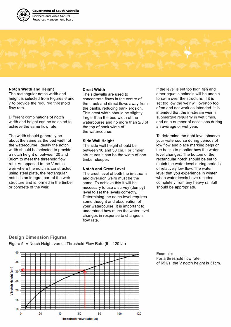
Example:For a threshold flow rateof 65 l/s, the V notch height is 31cm.
Design Dimension FiguresFigure 5: V Notch Height versus Threshold Flow Rate (5 – 120 l/s)
Government of South Australia
Northern and Yorke NaturalResources Management Board
Government of South Australia
Northern and Yorke NaturalResources Management Board
Government of South Australia
Northern and Yorke NaturalResources Management Board
Government of South Australia
Northern and Yorke NaturalResources Management Board
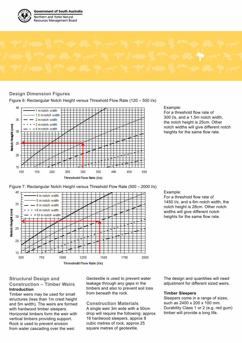
Example:For a threshold flow rate of300 l/s, and a 1.5m notch width, the notch height is 25cm. Other notch widths will give different notch heights for the same flow rate.
Example:For a threshold flow rate of1450 l/s, and a 6m notch width, the notch height is 28cm. Other notch widths will give different notch heights for the same flow rate.
Design Dimension FiguresFigure 6: Rectangular Notch Height versus Threshold Flow Rate (120 – 500 l/s)
Figure 7: Rectangular Notch Height versus Threshold Flow Rate (500 – 2000 l/s)
Structural Design and Construction – Timber WeirsIntroductionTimber weirs may be used for small structures (less than 1m crest height and 5m width). The weirs are formed with hardwood timber sleepers. Horizontal timbers form the weir with vertical timbers providing support. Rock is used to prevent erosion from water cascading over the weir.
Geotextile is used to prevent water leakage through any gaps in the timbers and also to prevent soil loss from beneath the rock.
Construction MaterialsA single weir 3m wide with a 50cm drop will require the following: approx 16 hardwood sleepers, approx 8 cubic metres of rock, approx 25 square metres of geotextile.
The design and quantities will need adjustment for different sized weirs.
Timber Sleepers Sleepers come in a range of sizes, such as 2400 x 200 x 100 mm. Durability Class 1 or 2 (e.g. red gum) timber will provide a long life.
Government of South Australia
Northern and Yorke NaturalResources Management Board
Government of South Australia
Northern and Yorke NaturalResources Management Board
Government of South Australia
Northern and Yorke NaturalResources Management Board
Government of South Australia
Northern and Yorke NaturalResources Management Board
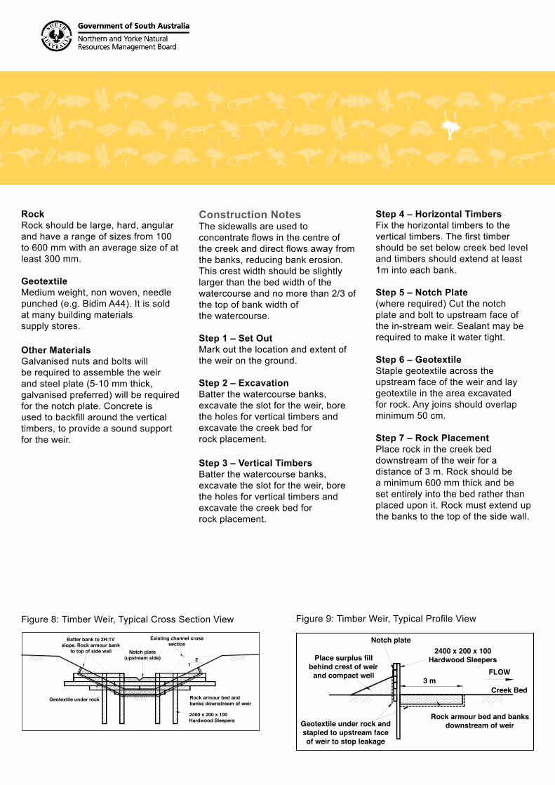
Batter bank to 2H:1V slope. Rock armour bank
to top of side wall
Geotextile under rock
2400 x 200 x 100Hardwood Sleepers
Rock armour bed and banks downstream of weir
Existing channel cross section
Notch plate(upstream side) 2
1
Figure 8: Timber Weir, Typical Cross Section View
RockRock should be large, hard, angular and have a range of sizes from 100 to 600 mm with an average size of at least 300 mm.
GeotextileMedium weight, non woven, needle punched (e.g. Bidim A44). It is sold at many building materials supply stores.
Other MaterialsGalvanised nuts and bolts will be required to assemble the weir and steel plate (5-10 mm thick, galvanised preferred) will be required for the notch plate. Concrete is used to backfill around the vertical timbers, to provide a sound support for the weir.
Construction NotesThe sidewalls are used to concentrate flows in the centre of the creek and direct flows away from the banks, reducing bank erosion. This crest width should be slightly larger than the bed width of the watercourse and no more than 2/3 of the top of bank width of the watercourse.
Step 1 – Set Out Mark out the location and extent of the weir on the ground.
Step 2 – ExcavationBatter the watercourse banks, excavate the slot for the weir, bore the holes for vertical timbers and excavate the creek bed for rock placement.
Step 3 – Vertical Timbers Batter the watercourse banks, excavate the slot for the weir, bore the holes for vertical timbers and excavate the creek bed for rock placement.
Step 4 – Horizontal TimbersFix the horizontal timbers to the vertical timbers. The first timber should be set below creek bed level and timbers should extend at least 1m into each bank.
Step 5 – Notch Plate(where required) Cut the notch plate and bolt to upstream face of the in-stream weir. Sealant may be required to make it water tight.
Step 6 – Geotextile Staple geotextile across the upstream face of the weir and lay geotextile in the area excavated for rock. Any joins should overlap minimum 50 cm.
Step 7 – Rock PlacementPlace rock in the creek bed downstream of the weir for a distance of 3 m. Rock should be a minimum 600 mm thick and be set entirely into the bed rather than placed upon it. Rock must extend up the banks to the top of the side wall.
2400 x 200 x 100
Hardwood Sleepers
Geotextile under rock and stapled to upstream face of weir to stop leakage
Rock armour bed and banks downstream of weir
3 mFLOW
Place surplus fill behind crest of weir
and compact well
Notch plate
Creek Bed
Figure 9: Timber Weir, Typical Profile View
Government of South Australia
Northern and Yorke NaturalResources Management Board
Government of South Australia
Northern and Yorke NaturalResources Management Board
Government of South Australia
Northern and Yorke NaturalResources Management Board
Government of South Australia
Northern and Yorke NaturalResources Management Board
Structural Design and Construction – Concrete WeirsIntroductionConcrete weirs may be used for structures up to 1m crest height, 30cm side wall height (above crest) and 10m crest width. The concept may be used for larger weirs however the structural details will need reassessment by a qualified engineer.
For reasons of safety (ie potential formwork collapse) and functional requirements (ie prevention of formwork deformation) construction must be undertaken by an experienced builder or civil works contractor.
Construction MaterialsConcrete Concrete must be N32 (32 MPa) with a maximum aggregate size of 20 mm and slump of 80mm.
Steel ReinforcementTwo types of steel reinforcement are required:• SL.82 reinforcing mesh must
be centrally placed in all heel, toe, crest, sidewall, cut-off and abutment walls and slabs.
• N12 deformed bars are required in the form of ‘L-bars’ to connect all junctions in the structure (ie at all wall/slab, wall/abutment and slab/cut-off wall junctions). These ‘L-bars’ shall have 400mm legs and be placed at 400mm centres along the junctions.
Construction NotesStep 1 – Set OutMark out the location and extent of the weir on the ground. Use a survey (dumpy) level to ensure that the levels of the in-stream and diversion weirs are the same, as discussed earlier.
Step 2 – ExcavationBatter the watercourse banks and excavate the bed and banks for the weir slab (heel and toe) and abutments. Excavate a trench for the cut-off wall, down to solid impermeable material. The cut-off wall and trench should be a minimum 50 cm deep. Where solid, impermeable material is at considerable depth, alternatives such as steel sheet piling may be used for the cut-off wall. Consult a qualified engineer.
Step 3 – FormworkFor safety as well as functional resons formwork should be designed and installed by an experienced builder or civil works contractor. Formwork must be rigid, watertight and constructed to AS3610, S.A.A. Formwork Code.
Step 4 – ReinforcementCut and install steel reinforcement mesh, and ‘L-bars’ in accordance with the drawings. All reinforcement must be firmly held in its required position and adequately supported by ‘chairs’ at approximately 750mm centres. Reinforcement is to be placed centrally within the walls, slabs and abutments. Splices in reinforcing mesh, if required, shall be equivalent to the cross-wire spacing plus 25mm.
Step 5 - Concrete Placement: Pour concrete to the design levels and compact using a mechanical vibrator to remove all entrained air and completely fill the formwork.
Step 6 - Concrete CuringCuring must be undertaken in accordance with AS3600, S.A.A. Concrete Structures Code. All exposed surfaces of the concrete must be kept moist be application of either a curing compound or by covering with polyethylene sheeting for at least 7 days.
Step 7 - Notch Plate(where required) Cut the notch plate, drill holes in the concrete weir and fix the plate to the upstream face of the in-stream weir. Sealant may be required to make the join water tight.
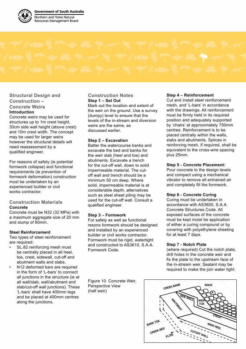
Figure 10. Concrete Weir, Perspective View (half weir)
CREEK BANK
CUTOFF WALLCREEK BED
CREST
SIDE WALL
WEIR HEELBANK TOE
WEIRTOE
ABUTMENT
FLOW
ROCK
June 2011
Government of South Australia
Northern and Yorke NaturalResources Management Board
Structural Design and Construction – Concrete Weirs
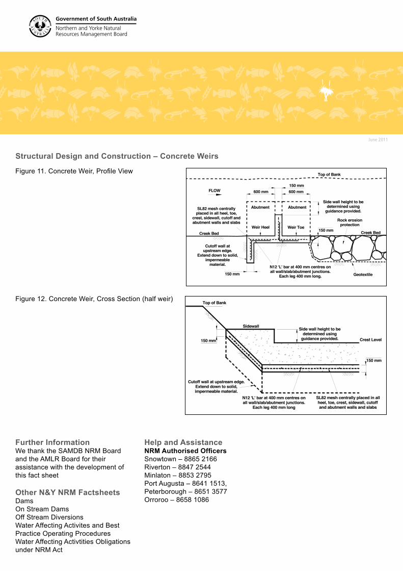
Figure 11. Concrete Weir, Profile View
Figure 12. Concrete Weir, Cross Section (half weir)
600 mm600 mm
150 mm
150 mm
150 mm
Cutoff wall at upstream edge.
Extend down to solid, impermeable
material.
SL82 mesh centrally placed in all heel, toe,
crest, sidewall, cutoff and abutment walls and slabs
Side wall height to be determined using
guidance provided.
Top of Bank
Weir ToeWeir Heel
Abutment Abutment
N12 'L' bar at 400 mm centres on all wall/slab/abutment junctions.
Each leg 400 mm long.
FLOW
Rock erosionprotection
Geotextile
Creek Bed Creek Bed
150 mm
150 mm
Cutoff wall at upstream edge. Extend down to solid, impermeable material.
Side wall height to be determined using
guidance provided.
Sidewall
Crest Level
Top of Bank
SL82 mesh centrally placed in all heel, toe, crest, sidewall, cutoff and abutment walls and slabs
N12 'L' bar at 400 mm centres on all wall/slab/abutment junctions.
Each leg 400 mm long
Further InformationWe thank the SAMDB NRM Board and the AMLR Board for their assistance with the development of this fact sheet
Other N&Y NRM FactsheetsDamsOn Stream Dams Off Stream DiversionsWater Affecting Activites and Best Practice Operating Procedures Water Affecting Activtities Obligations under NRM Act
Help and AssistanceNRM Authorised OfficersSnowtown – 8865 2166Riverton – 8847 2544Minlaton – 8853 2795Port Augusta – 8641 1513, Peterborough – 8651 3577Orroroo – 8658 1086