Embed Size (px)
Citation preview

Keywords: Life Assessment, Pressure Vessel, Piping, Petro-chemical Plant Service (FFS), In Service Inspection (ISI). ABSTRACT Fitness-for-service (FFS) assessments are quantitative engineering evaluations. It is required to be preformed periodically in accordance with the published codes and standards to demonstrate the structural integrity of in-service components. This script summarizes results of non-destructive In-Service-Inspection (ISI) of pressurized components conducted for condition assessment of Dakhani Gas Processing Plant of Oil and Gas Development Corporation Ltd. (OGDCL) for the first time since its commissioning in December,1989. The non-destructive evaluation of the plant was required because of concerns for occurrence of Sulphide-stress-cracking. Hydrogen embrittlement, hydrogen-including-cracking, weight-loss-corrosion, Sulphur-stress-corrosion due to detrimental service conditions at Dakhani having low PH, High H2S, high chlorides and pressure of CO2.
Results have shown that microstructural changes associated with first and second stage of hydrogen attack have occurred in almost all pipe joints and pressure vessels. Hardness of some vessels has even exceeded the NACE limit of 220 HB. Effect of second stage of hydrogen attack are dominant in pipe joints, resulting in loss of hardness and strength because of decarburization. The results based on ultrasonic attenuation monitoring also indicate degradation of components. Random rounded indications have also been observed in some pipe joints during X-Ray radiographic testing that could serve as sites for failure initiation. The corrosion-under-insulation is observed for joints of piping spreading over a significant length. Localized corrosion and pitting is also observed in some locations of pressure vessels and piping. Ultrasonic thickness gauging has shown a significant variation in thickness for dish-end, shell of some pressure vessels, joints of piping. In absence of periodic ISI data for the plant and keeping in view the results of non-destructive evaluation summarized above, the end-of-life(EOL) assessment of pressure vessels and piping is not possible and operation of the plant should be continued with a degree of caution. Any estimate of safe life assessment of the plant made at this stage would require revision on the basis of observed level of degradation through essential
LIFE
Prof. M. ShaDepartment of Mechanical Engineering
University of Engg & Tech Taxila, Pakistan [email protected]
Tel: 0092519047675, Fax:0092519047420
1
PES AND PRESSURE VESSELS OFMICAL PLANT
Prof. Sajjad Akbar Intl Islamic University, Islamabad, Pakistan
ICONE20-POWER2012-5
ASSESSMENT OF PI APETRO-CHE
hid Khalil
Proceedings of the 2012 20th International Conference on Nuclear Engineering collocated with the
ASME 2012 Power Conference ICONE20-POWER2012
July 30 - August 3, 2012, Anaheim, California, USA
4289
periodic in-service monitoring. In order to cope with the situation, it is recommended that monitoring of further degradation of microstructure and hardness along with flaw growth should be carried out after a period of 8x100 hours. Necessary remedial measures for rectification of flaws are requested. Non-destructive strain gauges are recommended to estimate data for safe life assessment of pressure vessels. Thermographic scanning of on-line in-service insulated pipelines is proposed for monitoring corrosion-under-insulation during plant operation. 1. INTRODUCTION TO LIFE ASSESSMENT Technology of fracture mechanics and non-destructive metallographic testing based on replication technique has been applied for assessment of safe operation of a petro-chemical plant. Fatigue crack growth rate assessment under various conditions, environmental and stress-corrosion problems, dynamic fracturing and determinations of the effects of elevated and cryogenic testing temperatures have been estimated by applying various codes and standards. Past experience in design, fabrication testing and failure analysis of many structures has indicated that crack like flaws may be present in as fabricated structures as well as in these structures after they have been exposed to service-stresses and service environments. Fracture mechanics technology in conjunction with non-destructive testing techniques provides the design procedures required to minimize catastrophic service failure originating from such flaws and cracks. Gas processing plant of public sector organizations ensure integrity of pipes and pressure vessels being used for extraction of crude oil from earth as well as in gas processing. Heavy investment will be involved for replacements. It is necessary that by utilizing the technology of fracture mechanics, life span of the pipe and pressure vessels being used will be assessed practically. 1.1 Inter Disciplinary Nature of Life Assessment All structures contain defects. The assessment of significance of defects and of component degradation is related to both safety and economics. In some cases, issue is principally that of economics, it may continue the operation which is necessary. Overall, the matter of “living with defeats” is part of ageing evaluation and reliability oriented plant
[email protected] Tel: 0092519019478
Copyright © 2012 by ASME

management. Assessment of defects and that of component degradation depends on technical impact from several subject areas such as materials, mechanics, and thermal and fluid mechanics engineering, such as biology, human factor and statistics, must be included in some cases. Life assessment is often a task performed by a team made of members of various disciplines. Team composition may also change during the problem. All evidences and theories for life assessment are evaluated by technically qualified individuals and therefore analysis moves from the various specialties to the “big picture” is utmost important in the operational setup. 1.2 Objectives of Research Primary aim and objective of this investigation is practical evaluation of life span of pipes and pressure vessels which are being used for extraction of crude oil and gas from earth. Hence, it is important to design general procedure for applications in such setup. Verification of plant integrity in a stress corrosion-cracking environment was also a requirement. The said objectives of this research will be obtained by studying the mechanical and micro-structural properties of used pipelines and vessels, weld procedures and weld inspections, carrying out chemical composition analysis by non-destructive testing. This technique will also be applied for the evaluation of structural integrity of existing piping network. 1.3 Research Methodology Following methodology will be utilized to complete tasks:- 1. In-situ inspection of components in the petro-chemical
industry 2. Various tests including destructive / non-destructive will
be carried out for life assessment. These tasks include: - a. Tensile strength by non-destructive means. b. Metallographic examination by non-destructive
means. c. Dimensional analysis by non-destructive means. d. Fracture toughness testing by non-destructive
techniques. e. Non-destructive flaw monitoring based on ultra-
sonic techniques. Life assessment based on assessment code BS-PD-6493 will be evaluated. 2. Literature Review The main source of latest information, literature and continuing education is Internet which was used for the collection of updated information about life assessment of pipes and pressure vessels of petro-chemical plant. Internet facility was also used to get information about latest research going on in various universities, professional societies and organizations around the world on life assessment of pipes and pressure vessels. 2.1 J.F Knott Past experience in design, fabrication testing and failure analysis of many structures has indicated that crack like flaws may be presented in as fabricated structures as well as in these structures after they have been exposed to service stresses and services environments. J.F Knott "Fundamental aspects of fracture mechanic" provides the
design procedures required to minimize catastrophic services failures originating from such flaws and cracks. 2.2 Metallurgical Transaction Volume 14-A No. 4 Trace elements and interfaces play pivotal roles in nucleation, growth and inter linkage of grain boundary cavities, ultimately leading to inter-granular failure during creep. These interfaces, along with the cavity surfaces themselves, are also sites for trace elements segregation. The proceedings address individual aspects of deformation and cavitations with emphasis on the role of segregation impurities, the effects of trace-element on grain boundary cavitations: in specific alloy system were referred and are published in this issue of Metallurgical Transactions. 2.3 Dr. RB Tait The intent of codes is to regulate safety standards applied to plant operation under hazardous circumstances. For supporting a code conformance approach, adequate understanding of the principle involved, especially the performance of the NDT methods and the bearing of NDT performance on structural integrity and hence risk of operation, is development of NDT techniques, inspection validation, in having published technical literature, the development of codes and standards in addition to demonstrable, appropriate personnel qualifications of experience. 2.4 “Volume 10 of 8th Edition of Failure Analysis and Prevention American Society for Metals Publications, 1975 This deals not only with the analysis of failure but also with effective measures for failure prevention by improving product performance and reliability. As a technical term, "failure" means cessation of function or usefulness. A greater under standing of its scope and contents may be derived from the following summary of the four principal sections or subdivision of this volume. 1. Engineering aspects, of failure and failure analysis. 2. Failure from various mechanics and related
environmental factors. 3. Analysis and prevention for services failure products of
principal material working process. 4. Analysis and prevention of services .failure
manufactured components and assemblies. 2.5 William A Nash 1983 Each chapter begins with a summery of the pertinent definitions, principals and theorems followed by graded sets of solved and supplementary problems Strength of materials have become more sophisticated and frequently tend to include topics in plastic analysis and design, treatments of shear centers, curved beams and use of singularity functions to describe beam behavior. Strain energy methods of analysis and the elements of theory of elasticity have been solved. 2.6 British Standard Institution (BSI) “Guidance on Methods for Assessing The Acceptability of Flaws in Fusion Welded Structures These published documents give guidance on methods for assessing the acceptability of flaws in all type of fusion welded structures and components although specifically, aimed at Welded fabrications in ferritic and austenitic steels
2 Copyright © 2012 by ASME

and aluminum alloys, the procedures developed can be used for analyzing flaws in welds in other materials and in non welded applications. 3. Non-Destructive Testing (Ndt) 3.1 Leak Testing (Lt) Since many structures are designed to be pressurized or pressure tight, defect is often a leak. There are several methods (Table 1) for locating leaks ranging from simple liquid seepage onto a dry surface, perhaps mixed with a dye, to highly precise measurement of the escape of helium or radioactive gas. The level of sensitivity depends upon the methods used and is chosen in relation to the severity of the application. Some of the advantages of leak testing are: 1. It is very sensitive to holes or separations not detected
by other methods. 2. It can be rapid. 3. It can be inexpensive. Some of the limitations of this method are: 1. Costs vary with methods. 2. Open systems can not be tested. 3. Type or cause of defect may not be identified. 4. It can require special materials and equipment. Table 1: Comparison of variouTable 1: Comparison of variouTable 1: Comparison of variouTable 1: Comparison of various NDT methodss NDT methodss NDT methodss NDT methods
Technique Access requirements
Remarks
Optical methods
Can be used to view of interior of complex equipment. One point of access may be enough.
Very versatile; little skill required; repays consideration at design stage.
Radiography Must be able to reach both sides
Despite high cost large area can be inspected at one time. Considerable skill required in interpretation.
Ultrasonic One or both sides( or both ends) must be accessible.
Requires point-by-point search hence extensive work needed on large structures; skilled personnel required.
Magnetic particle
Requires a clean and reasonably smooth surface.
Only useful on magnetic materials such as steel; Little skill required; Only detects surface breaking or near surface cracks.
Penetrate flaw
Requires flaw to be accessible to the penetrate ( i.e. clean and at the surface)
For all materials; Some skill required: Only detects surface-breaking defects; Rather messy.
Eddy Current
Surface must (usually) be reasonably smooth and clean
For electrically conductive materials only; for surface breaking flaws; variations in thickness of coating, or comparison of materials; for other than simple comparison considerable skill is usually required.
3.2 Comparison of Different NDT Methods Frequently it may be necessary to use one method of NDT to confirm the findings of another. Therefore, various methods must be considered complementary and not competitive, or as optional alternatives. Each method has its particular merits and limitations and these must be taken into account when
any testing program is planned.
4. Scope Of Work, Codes And Standards, Mode Of Evaluation And Testing Equipments For Life Assessment
4.1 Introduction Gas processing plant of public sector organization wants to ensure integrity of pipes and pressure vessels. It is being used for extraction of crude oil from earth as well as in gas processing. Heavy investment will be involved for their replacements. It is necessary that by utilizing the technology of fracture mechanics, life span of the pipes and pressure vessels being used will be assessed practically. 4.2 Scope of Work Fitness for service assessment are quantitative engineering evaluation which are required to be performed periodically in accordance with the published codes and standards to demonstrate the structural integrity of in-service components. Following code and standards have applied during non destructive evaluation (NDE) of vessels and piping: - 1. American Petroleum Institute (API) recommended
Practice 579, First Edition, January 2000. 2. National Association of Corrosion Engineers (NACE)
Standard MR-01-75 (1986 Editorial Revision). 3. American Society of Mechanical Engineers (AS ME)
Boiler and Pressure Vessel Code, Section XI, 1995 4. British Standard Institution (BSI) Standard 7910: 1999 5. British Standard Institution (BSI) published Document
PD 6493: 1991 Note: The Nuclear Engineering Plant and Petrochemical Plant have different industrial codes and standards but the life assessment of proposed pressure vessel testing techniques are similar / same. 4.3 Mode of Evaluation In order to conduct non-destructive evaluation (NDE) as per scope of work by applying codes/standards, the following work plan was adopted: - 1. Conduct non-destructive hardness testing of weld
region, heat-affected-zone (HAZ) and parent material and check nickel-content in some locations.
2. Apply liquid penetrate or magnetic particle testing for location and sizing of surface flaws
3. Conduct ultrasonic defect monitoring for location and sizing of subsurface flaws. Use X-ray radiographic testing for recording or confirmation of defects where required
4. Monitor degradation of material by determination of attenuation co-efficient based on ultrasonic attenuation technique.
5. Conduct a survey for determination of WLC by ultrasonic thickness gauging.
6. Conduct non-destructive metallographic testing based on replication technique to determine microstructural degradation.
7. Conduct condition assessment based on fracture mechanics by applying codes and standards.
4.4 Testing Equipments The following equipment of non-destructive evaluation were used for condition assessment. 1. Non-destructive hardness testing equipment (Equotip,
3 Copyright © 2012 by ASME
Switzerland) 2. Non-destructive metallographic replication equipment
(Struer, Denmark) 3. Ultrasonic flaw detector(Krautkramer, Germany) 4. Ultrasonic thickness gauge(Krautkramer, Germany) 5. Magnetic particle testing equipment (Magnaflux, U.K) 6. X-ray radiographic testing system(Philips, Germany) 7. Optic-Fiber borescope( Machinda, Japan) 8. Koslow kit.
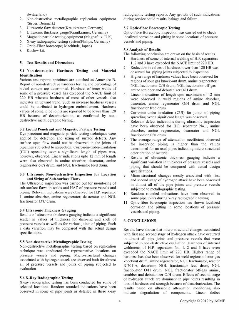
5. Test Results and Discussions 5.1 Non-destructive Hardness Testing and Material Identification Various test reports specimen are attached as Annexure B. Report of non-destructive hardness testing and percentage of nickel content are determined. Hardness of inner welds of some of a pressure vessel has exceeded the NACE limit of 220 HB whereas hardness of most of other vessels also indicates an upward trend. Such an increase hardness vessels could be attributed to hydrogen embrittlement. Hardness values of some, pipe joints are reported to be lower than 120 HB because of decarburization, as confirmed by non-destructive metallographic testing. 5.2 Liquid Penetrant and Magnetic Particle Testing Dye-penetrant and magnetic particle testing techniques were applied for detection and sizing of surface defects. Any surface open flaw could not be observed in the joints of pipelines subjected to inspection. Corrosion-under-insulation (CUI) spreading over a significant length of pipes was, however, observed. Linear indications upto 12 mm of length were also observed in amine absorber, deaerator, amine regenerator O/H drum, and NGL fractionator feed drum. 5.3 Ultrasonic Non-destructive Inspection for Location
and Sizing of Sub-surface Flaws The Ultrasonic inspection was carried out for monitoring of sub-surface flaws in welds and HAZ of pressure vessels and piping. Relevant indications were observed for H.P. separator 1, amine absorber, amine regenerator, de aerator and NGL fractionator O/H drum. 5.4 Ultrasonic Thickness Gauging Results of ultrasonic thickness gauging indicate a significant scatter in values of thickness for dish-end and shell of pressure vessels as well as for various joints of piping. Such a data variation may be compared with the actual design specifications. 5.5 Non-destructive Metallographic Testing Non-destructive metallographic testing based on replication technique was conducted for representative locations on pressure vessels and piping. Micro-structural changes associated with hydrogen attack are observed both for almost all of pressure vessels and joints of piping subjected to evaluation. 5.6 X-Ray Radiographic Testing X-ray radiographic testing has been conducted for some of selected locations. Random rounded indications have been observed in some of pipe joints as detailed in these x-ray
radiographic testing reports. Any growth of such indications during service could results leakage and failure. 5.7 Optic-fibre Borescopic Testing Optic-Fibre Borescopic inspection was carried out to check localized corrosion and pitting in some locations of pressure vessels and piping. 5.8 Analysis of Results The following conclusion are drawn on the basis of results 1 Hardness of some of internal welding of H.P. separators
1, 2 and 3 have exceeded the NACE limit of 220 HB. 2 Reduction in values of hardness lower than 120 HB was
observed for piping joints subjected to inspection. 3 Higher range of hardness values have been observed for
regions of sour gas knock-out drum, amine regenerator, NGL fractionator O/H drum, NGL fractionator off-gas amine scrubber and debutanizer O/H drum.
4 Linear indications of length upto maximum of 12 mm were observed in weld regions of amine absorber, deaerator, amine regenerator O/H drum and NGL fractionator feed drum.
5 Corrosion-under-insulation (CUI) for joints of piping spreading over a significant length was observed.
6 Relevant defect indications during ultrasonic inspection have been observed for H.P. separator No.1, amine absorber, amine regenerator, dearerator and NGL fractionator O/H drum.
7 The average range of attenuation coefficient observed for in-service piping is higher than the values determined for un-used pipes indicating micro-structural deterioration of material
8 Results of ultrasonic thickness gauging indicate a significant variation in thickness of pressure vessels and piping that should be compared with actual design specifications.
9 Micro-structural changes mostly associated with first and second stage of hydrogen attack have been observed in almost all of the pipe joints and pressure vessels subjected to metallographic testing.
10 Random rounded indications have been observed in some pipe joints during x-ray radiographic testing
11 Optic-fibre baroscopic inspection has shown localized corrosion and pitting in some locations of pressure vessels and piping.
6. CONCLUSIONS Results have shown that micro-structural changes associated with first and second stage of hydrogen attack have occurred in almost all pipe joints and pressure vessels that were subjected to non-destructive evaluation. Hardness of internal weldments of H.P. separators No. I, 2 and 3 have even exceeded the NACE limit of 220 HB. Higher range of hardness has also been observed for weld regions of sour gas knockout drum, amine regenerator, NGL fractionator, reactor R-701-A, deaerator, NGL fractionator feed drum, NGL fractionator O/H drum, NGL fractionator off-gas amine, scrubber and debutanizer O/H drum. Effects of second stage of hydrogen attack are dominant in pipe joints resulting in loss of hardness and strength because of decarburization. The results based on ultrasonic attenuation monitoring also indicate degradation of components. Linear defect
4 Copyright © 2012 by ASME

indications have been observed, in weld regions of amine absorber, deaerator, amine regenerator O/H drum and NGL fractionator feed drum. Fitness-for-service (FFS) assessments are quantitative engineering evaluations which are required to be performed periodically in accordance with the published codes and standards to demonstrate the structural integrity of in-service components. This script summarized the results of non-destructive in-service inspection (ISI) of pressurized components conducted for condition assessment of the Dakhani Gas Processing Plant of Oil and Gas Development Corporation Ltd. (OGDCL) for the first time since its commissioning in December, 1989. Random rounded indications have also been observed in some pipe joints during x-ray radiographic testing that could serve as sites for failure initiation. The corrosion-under insulation is observed for joints of piping spreading over a significant length. Localized corrosion and pitting is also observed in some locations of pressure vessels and piping. Ultrasonic thickness gauging has shown a significant variation in thickness for dish-end and shell of some pressure vessels as well as for various joints of piping. 6.1 Recommendations In absence of periodic ISI data for the plant and keeping in view the results of nondestructive evaluation summarized above, the end-of-life (EOL) assessment of pressure vessels and piping is not possible and operation of the Plant should be continued with a degree of caution. Any estimate of safe life assessment of the Plant made at this stage would require revision on the basis of observed level of degradation of microstructure and hardness along with flaw growth should be carried out after a period of 8xl03 hours. Necessary remedial measures for rectification of flaws are required for amine absorber, deareator, amine regenerator O/H drum and NGL fractionator feed drum. Nondestructive strain gauging is recommended to estimate data for safe life assessment of pressure vessels. Thermographic scanning of on-line, in-service insulated pipelines is proposed for monitoring corrosion-under-insulation during plant operation.
REFERENCES Metallurgical Transaction Volume 14-A No.4, April 1983 Dr.RB Tait "Mechanical Properties and Elementary Fracture Mechanics" Mechanical Engg. Dept. Cape Town University, South Africa, Oct. 1977 LA.E.A. Technology Publication. J.F Knott "Fundamentals of Fracture Mechanics" Mc Graw Hill Inc, 1984 Kare Hallen "Introduction of Fracture Mechanics" Mc Graw Hill Inc, 1976 "Volume10 of 8th Edition of Failure Analysis and Prevention" American Socity for Metals Publications, 1975 William A Nash "Theory and Problems of Strength of
Materials 21 Edition Schaum's Out Line Series" Mc Graw Hill Inc. Singapore, March 1983 British Standard Institution (BSI) Published Document PD-6493: 1991 "Guidance on Methods for assessing the acceptability of Flaws in Fusion Welded Structures” Taylor Lyman “Quantitative Metallography” Volume 8, 8th Edition American Society for Metals Pubications, 1973. American Petroleum Institute (API) Recommended Practice 579, First Edition, Janurary 2000 National Association of Corrosion Engineers (NACE) Standard MR—01-75 (1986 Editorial Revision) American Society of Mechanical Engineers (ASME) Boiler and Pressure Vessel Code, Section XI,1995 British Standard Institution (BSI) Standard 7910:1991 British Standard Institution (BSI) Published document PD 6493: 1991
5 Copyright © 2012 by ASME

ANNEXURE B
Fig 1 Ultrasonic Inspection Report
Fig 2. Borescopic Inspection Report
6 Copyright © 2012 by ASME

Fig.3 Hardness Report Test
Fig 4 Dye Penetrant Inspection Report
7 Copyright © 2012 by ASME

Fig. 5 Magnetic particle Inspection Report
8 Copyright © 2012 by ASME

Fig 6. Radiographic Inspection Report
9 Copyright © 2012 by ASME