Embed Size (px)
Citation preview
Sewer Design Manual Page 1 of 11 September 2009
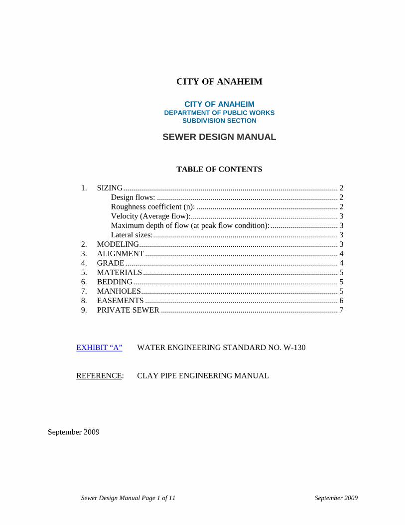
CITY OF ANAHEIM
CITY OF ANAHEIM DEPARTMENT OF PUBLIC WORKS
SUBDIVISION SECTION
SEWER DESIGN MANUAL
TABLE OF CONTENTS 1. SIZING ............................................................................................................ 2
Design flows: ........................................................................................... 2 Roughness coefficient (n): ....................................................................... 2 Velocity (Average flow): .......................................................................... 3 Maximum depth of flow (at peak flow condition): .................................. 3 Lateral sizes: ............................................................................................. 3
2. MODELING .................................................................................................... 3 3. ALIGNMENT ................................................................................................. 4 4. GRADE ........................................................................................................... 4 5. MATERIALS .................................................................................................. 5 6. BEDDING ....................................................................................................... 5 7. MANHOLES ................................................................................................... 5 8. EASEMENTS ................................................................................................. 6 9. PRIVATE SEWER ......................................................................................... 7
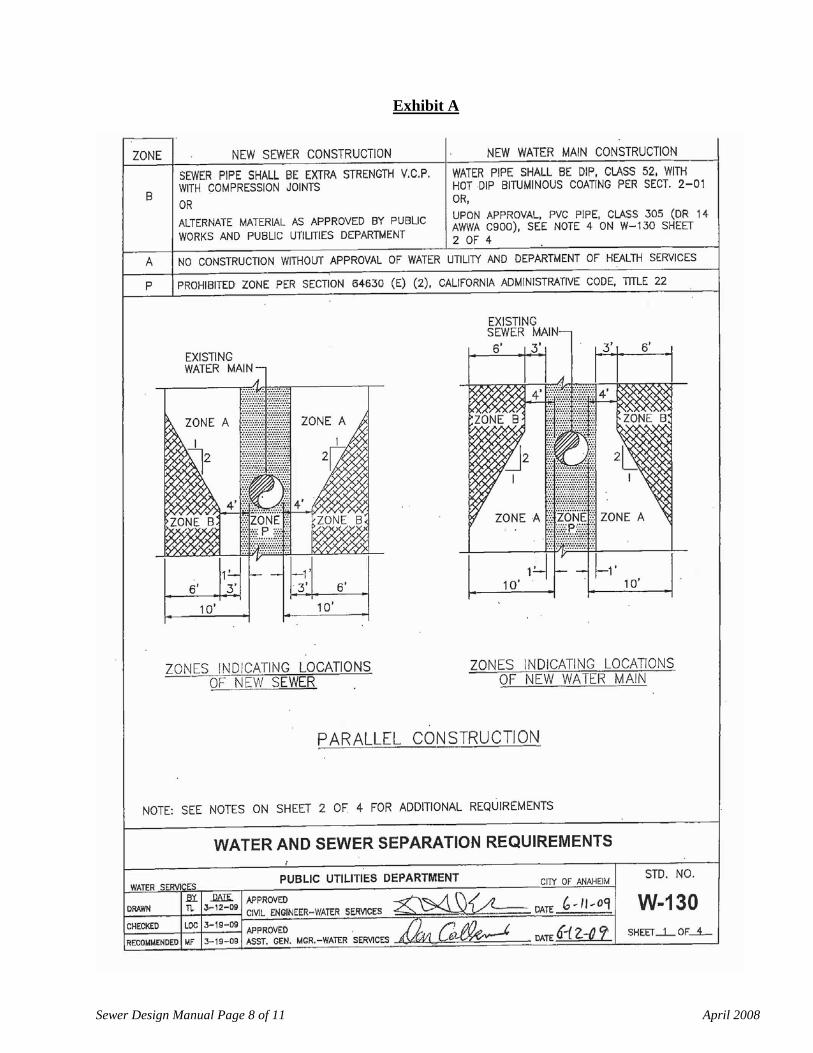
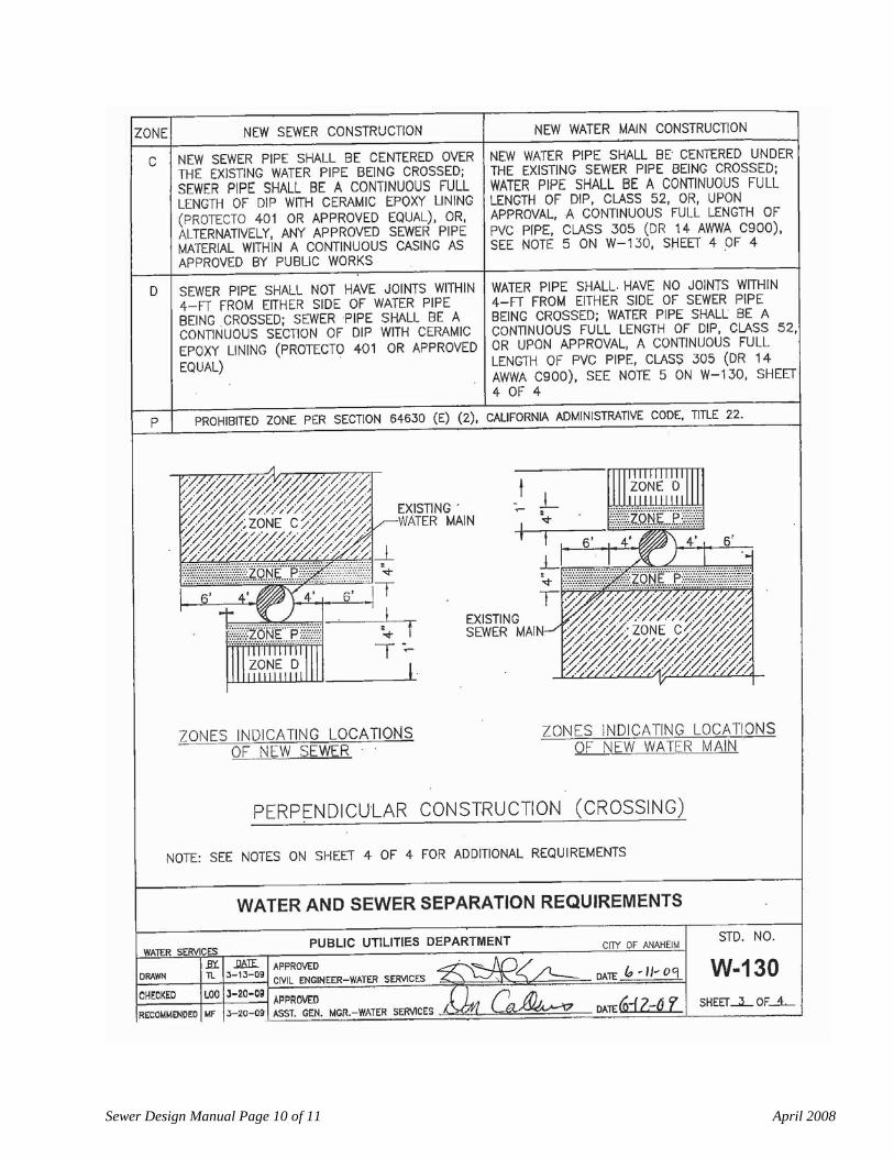
EXHIBIT “A” WATER ENGINEERING STANDARD NO. W-130
REFERENCE
: CLAY PIPE ENGINEERING MANUAL
September 2009

Sewer Design Manual Page 2 of 11 April 2008
SEWER DESIGN MANUAL
Sanitary sewers are designed primarily to carry to a satisfactory point of treatment and ultimate disposal the spent water supply of a community, industrial wastes and unavoidable amounts of ground water infiltration. All waters not containing impurities which are actually or potentially objectionable should be excluded as far as possible from the sanitary sewer system. The flow rates of sewage for which sewer capacity should be provided must be determined from careful considerations of the present and probable future quantities of domestic sewage and commercial and industrial wastes. The objective of the Sewer Design Manual is to provide a concise guide for the analysis and design of sewer facilities in the City of Anaheim. This guide is intended to be used by design engineers for development projects. Plan preparation and submittal requirements are provided in a separate document “Improvement Procedures” available online at: 1.
SIZING
Since the quantity of domestic sewage is a function of the population and of water consumption, lateral and sub main sewers should be designed for the saturation density of population expected in the areas served. The sewer system should be designed for tributary areas, land use and population estimated based on the Anaheim General Plan and Master Plan of Sanitary Sewers.
All sewers shall be designed based on the peak flow rate and the following criteria.
A minimum pipe size of 8" shall be used for all public sewers and private sewers within street.
Design flows:
The average daily flow of sewage and ground water is the average 24-hour discharge during a period of a year. The peak flow determines the hydraulic capacity of sewers.
Residential: Average flow: 105 gpcd (gallons per capita per day) Per capita factor: 3.3 people per household Peak factor: 3.25
Non-Residential:
Commercial: 2,262 gpd/acre Industrial: 3,167 gpd/acre Institutional: 2,715 gpd/acre Peak factor: 1.7
Lot coverage varies from 40 to 70% depending upon location.
Roughness coefficient (n):
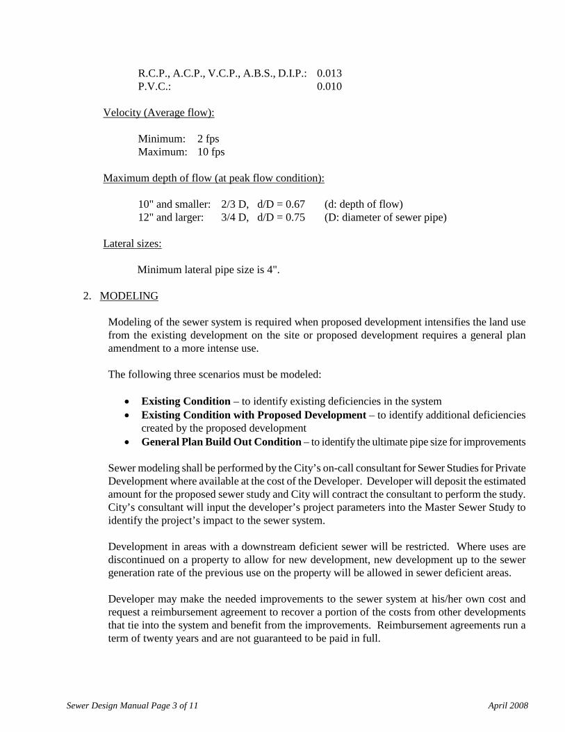
Sewer Design Manual Page 3 of 11 April 2008
R.C.P., A.C.P., V.C.P., A.B.S., D.I.P.: 0.013 P.V.C.: 0.010
Velocity (Average flow):
Minimum: 2 fps Maximum: 10 fps
Maximum depth of flow (at peak flow condition):
10" and smaller: 2/3 D, d/D = 0.67 (d: depth of flow) 12" and larger: 3/4 D, d/D = 0.75 (D: diameter of sewer pipe)
Lateral sizes:
Minimum lateral pipe size is 4".
2.
MODELING
Modeling of the sewer system is required when proposed development intensifies the land use from the existing development on the site or proposed development requires a general plan amendment to a more intense use. The following three scenarios must be modeled:
• Existing Condition – to identify existing deficiencies in the system • Existing Condition with Proposed Development – to identify additional deficiencies
created by the proposed development • General Plan Build Out Condition – to identify the ultimate pipe size for improvements
Sewer modeling shall be performed by the City’s on-call consultant for Sewer Studies for Private Development where available at the cost of the Developer. Developer will deposit the estimated amount for the proposed sewer study and City will contract the consultant to perform the study. City’s consultant will input the developer’s project parameters into the Master Sewer Study to identify the project’s impact to the sewer system. Development in areas with a downstream deficient sewer will be restricted. Where uses are discontinued on a property to allow for new development, new development up to the sewer generation rate of the previous use on the property will be allowed in sewer deficient areas. Developer may make the needed improvements to the sewer system at his/her own cost and request a reimbursement agreement to recover a portion of the costs from other developments that tie into the system and benefit from the improvements. Reimbursement agreements run a term of twenty years and are not guaranteed to be paid in full.
Sewer Design Manual Page 4 of 11 April 2008
3.
ALIGNMENT
Sewer shall be located in the street, not in the parkway. Sewer trench shall not extend under edge of gutter.
A minimum radius of 150' shall be used for any horizontal bend. Maximum deflection at any joint shall not exceed two (2) degrees. Connection:
4” to main line (8" or larger): saddle 6” to main line (8" or larger): snap-in wye 8” to main line (8" or larger): manhole
When jacking is required, details to be shown on plans. 18" minimum diameter C.I.P. with 3/8" wall thickness required for 8" V.C.P. Jacking may be required by the City Engineer when crossing arterial highways.
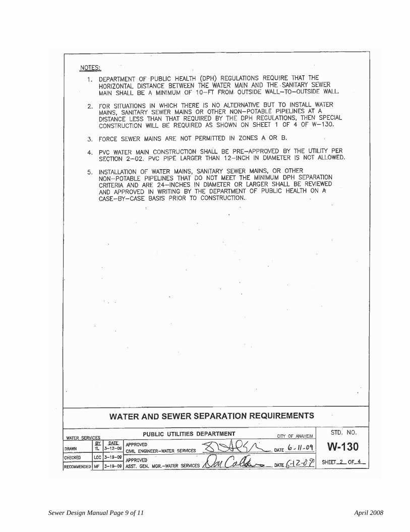
Minimum horizontal spacing between sewer line and water line is 11'.
Provide lateral for each lot per Standard Detail No's. 222-1 and 223-1.
4.
GRADE
Sewer shall be normally 7' to 8' deep (to soffit of pipe). Mainline minimum depth at manhole shall be 5.67 ft (5'- 8").
Minimum slope:
d= 8” d= 10” d= 12” d= 15”
s = 0.0036 s = 0.0030 s = 0.0024 s = 0.0020
Indicate slope in terms of s = 0.002, not s = 0.2%.
Avoid vertical curves. Straight grade from manhole to manhole. Use of vertical curve must be approved by the Development Services Manager.
Elevation drop thru manhole:
Straight thru: no change in pipe size, Match soffit: right angle turns and change in pipe size, 0.10' drop: turns and no change in pipe size, 0.20' drop: right angle turns and no change in pipe size.
Avoid drop manholes. Use of drop manholes to be approved by the Development Services Manager. Encasement is required when clearance between pipes is less than 18" and where required per
Sewer Design Manual Page 5 of 11 April 2008
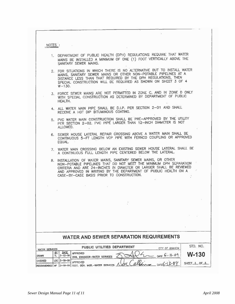
Water Engineering Standard No. W-130 (See Exhibit “A”)
Encase sewer line per Standard Detail No. 225-1 when:
• Top of bell of sewer is less than 3' from bottom of water line, • Storm drain is within 1.5' (18") above sewer line, or • Sewer line is above water line.
Slope anchors and backfill stabilizers are required where pipe slope exceeds 30%. Slope anchors shall be placed per Standard Detail No. 221-1.
5.
MATERIALS
Main line sewer pipe shall be V.C.P.
Sewer pipe under median to be D.I.P. epoxylined, polylined D.I.P. or V.C.P. encased.
A.B.S. and P.V.C. solid wall pipe and A.B.S. composite pipe may be used as an alternate to V.C.P. as approved by the City Engineer. Use shall be limited to local interior streets and private streets tributary to residential flows only. Sizes shall not exceed 10" in diameter. Pipe characteristics and installation shall be per the Standard Specifications for Public Works Construction and a Bedding Detail shall be provided.
V.C.P. joints shall be mechanical compression or Band seal type.
6.
BEDDING
V.C.P. and D.I.P. – Per Standard Specifications for Public Works Construction (“Greenbook”) for cover between 3' and 15', for cover less than 3' and greater than 15' special bedding is required. Calculations and supporting soils reports to be provided by the Design Engineer. Use a soil weight of 130 lbs/cf (unless soils reports state otherwise) and a safety factor of 1.5. Details of bedding shall be shown on plan.
A.B.S. and P.V.C. - Details of bedding shall be shown on plan. Supporting calculations are required.
7.
MANHOLES
Manholes to be constructed at intersecting mains, B.C., E.C., angle points and change in pipe size or grade. Only one manhole at B.C. or E.C. is acceptable for a short length curve (Maximum 100’) with a central angle less than 45 degrees.
Maximum manhole spacing is 300'. Manhole shall be constructed at the end of construction with 4' stub out for future connection. Stub shall be plugged with brick and mortar.
Sewer Design Manual Page 6 of 11 April 2008
In unpaved areas where there is a danger of the manhole becoming lost, set the top of cover elevation so as not to be less than 1' above existing ground.
8.
EASEMENTS
When sewer cannot be located within the street, it shall be located in an approved easement. Easements parallel to lot line shall be on one lot only. Sewer easement shall be a minimum 15 ft. in width. For deep pipe the easement shall be 2 x depth - O.D. to a maximum 25 ft. Access for maintenance of a public sewer shall be 12' wide and must be paved with 0.25' of A.C. over 0.35' of B.M. Location of access to be approved by the Streets and Sanitation Division. Easement for public sewers shall be dedicated to the City on a recorded map or by a separate deed with the approved easement sketch and the legal description (including closure calculations).
Sewer Design Manual Page 7 of 11 April 2008
9.
PRIVATE SEWER
Private on-site sewers designed to meet the California Plumbing Code will be reviewed, permitted and inspected by the Building Division. These plans will not be reviewed by the Public Works Department, but must meet all requirements of the California Plumbing Code and the Building Division. Contact the City of Anaheim Building Division at (714) 765-5153 for plumbing plan check requirements. Engineered Sewers (i.e. those within a private street or on-site systems that do not meet Plumbing Code) may be drawn in plan view only, however they must show rates of grade, direction of flow, size of pipe, invert and finish surface elevations at cleanouts, manholes and grade breaks, location and elevation of all adjacent or crossing underground facilities, sufficient horizontal controls to permit the system to be located in the field, and any other information which may be required to adequately check, construct and inspect the system.
A. The size of all sewers shall be designed based on the following desirable engineering
considerations, peak rate of flow with a minimum velocity of 2 fps, a minimum depth of flow of 1 inch and a maximum ratio of depth of flow to the diameter of pipe of 0.75. In addition, the minimum sizes shall be used:
a. Mains:
• Residential development: 6" min. • Commercial development: 6" min. • Industrial development: 4" min.
c. Laterals:
• 4" min. when serving 1 thru 6 living units in a single building, • 6" min. when serving more than 6 living units in a single building or more than one
(1) building.
B. Cleanouts may be provided in lieu of manholes at a maximum spacing of 100 feet. They shall also be provided at vertical grade break of more than one-half percent (1/2%) or for horizontal deflection angle of more than forty five (45) degrees. All cleanouts shall be brought to finished grade.
Standard manholes may be required when deemed necessary by the City Engineer.
C. Add note to each sheet:
APPROVED ONLY FOR INSPECTION OF WORKMANSHIP AND MATERIALS ON PRIVATE PROPERTY
Sewer Design Manual Page 8 of 11 April 2008
Exhibit A
Sewer Design Manual Page 9 of 11 April 2008
Sewer Design Manual Page 10 of 11 April 2008
Sewer Design Manual Page 11 of 11 April 2008