Embed Size (px)
Citation preview
State of North Carolina | Department of Transportation | Contract Standards and Development Unit
1020 Birch Ridge Drive | 1591 Mail Service Center | Raleigh, NC 27699-1591
919 707 6900
July 29, 2016
Addendum No. 1
Contract No.: C203862
TIP No.: U-2827B / C-5620A
County: Forsyth
Project Description: US 421 / I-40 Business Pavement Reconstruction, Bridge Replacements
and Interchange Modifications from west of Fourth Street to east of
Church Street; and Multi-Use Path from Fourth Street to Liberty Street
RE: Addendum No. 1 to Final RFP
August 30, 2016 Letting
To Whom It May Concern:
Reference is made to the Final Request for Proposals dated July 20, 2016 recently furnished to
you on the above project. We have since incorporated changes, and have attached a copy of
Addendum No. 1 for your information. Please note that all revisions have been highlighted in
gray and are as follows:
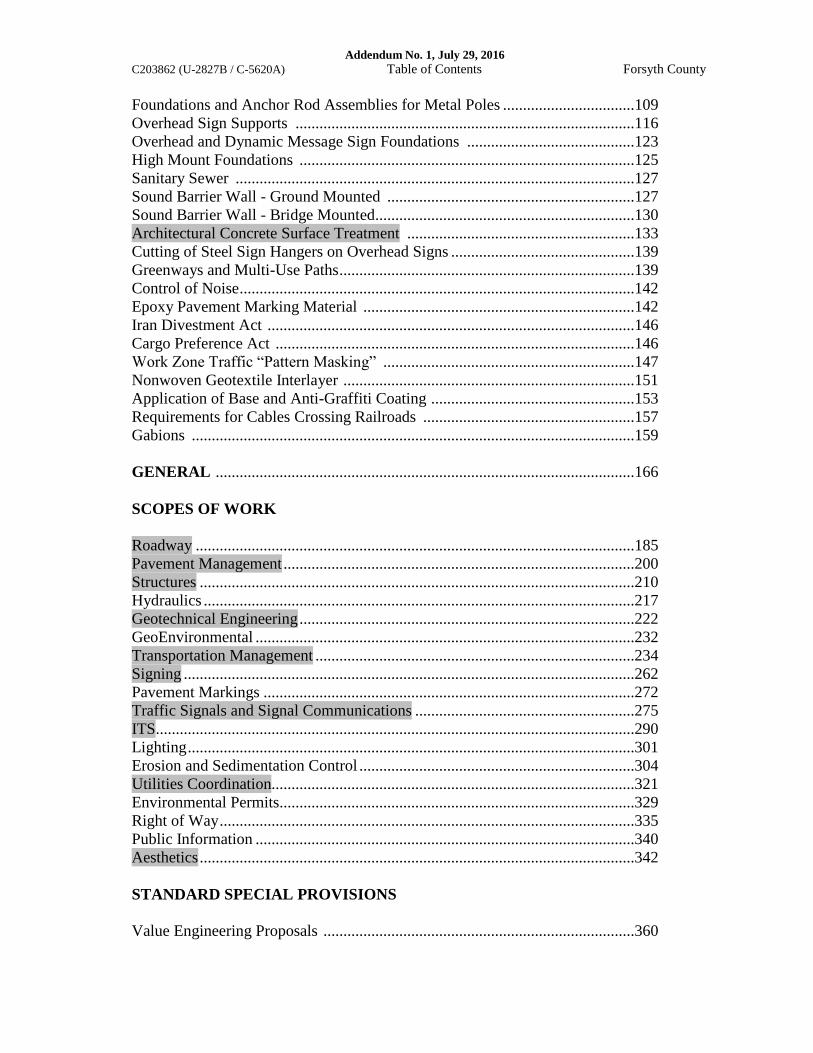
The second page of the Table of Contents has been revised. Please void the second page in your
proposal and staple the revised second page thereto.
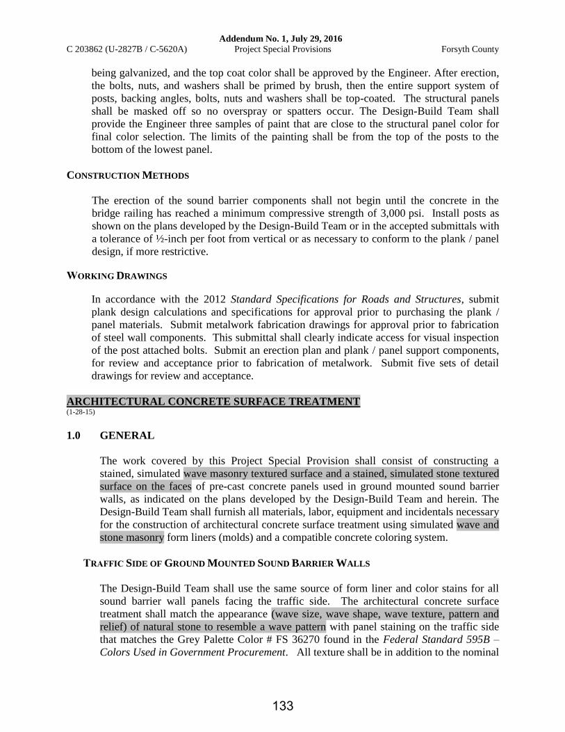
Page Nos. 133 and 134 of the Architectural Concrete Surface Treatment Project Special
Provision have been revised. Please void Page Nos. 133 and 134 in your proposal and staple the
revised Page Nos. 133 and 134 thereto.
Page Nos. 185, 186, 191, 194 and 196 of the Roadway Scope of Work have been revised. Please
void Page Nos. 185, 186, 191, 194 and 196 in your proposal and staple the revised Page
Nos. 185, 186, 191, 194 and 196 thereto.
Page No. 204 of the Pavement Management Scope of Work has been revised. Please void Page
No. 204 in your proposal and staple the revised Page No. 204 thereto.
Page Nos. 212, 214 and 215 of the Structures Scope of Work have been revised. Please void
Page Nos. 212, 214 and 215 in your proposal and staple the revised Page Nos. 212, 214 and 215
thereto.
Page Nos. 226 and 227 of the Geotechnical Engineering Scope of Work have been revised.
Please void Page Nos. 226 and 227 in your proposal and staple the revised Page Nos. 226 and
227 thereto.
Addendum No. 1, July 29, 2016
C203862 (U-2827B / C-5620A) Table of Contents Forsyth County
Foundations and Anchor Rod Assemblies for Metal Poles .................................109
Overhead Sign Supports .....................................................................................116
Overhead and Dynamic Message Sign Foundations ..........................................123
High Mount Foundations ....................................................................................125
Sanitary Sewer ....................................................................................................127
Sound Barrier Wall - Ground Mounted ..............................................................127
Sound Barrier Wall - Bridge Mounted.................................................................130
Architectural Concrete Surface Treatment .........................................................133
Cutting of Steel Sign Hangers on Overhead Signs ..............................................139
Greenways and Multi-Use Paths ..........................................................................139
Control of Noise ...................................................................................................142
Epoxy Pavement Marking Material ....................................................................142
Iran Divestment Act ............................................................................................146
Cargo Preference Act ..........................................................................................146
Work Zone Traffic “Pattern Masking” ...............................................................147
Nonwoven Geotextile Interlayer .........................................................................151
Application of Base and Anti-Graffiti Coating ...................................................153
Requirements for Cables Crossing Railroads .....................................................157
Gabions ...............................................................................................................159
GENERAL .........................................................................................................166
SCOPES OF WORK
Roadway ..............................................................................................................185
Pavement Management ........................................................................................200
Structures .............................................................................................................210
Hydraulics ............................................................................................................217
Geotechnical Engineering ....................................................................................222
GeoEnvironmental ...............................................................................................232
Transportation Management ................................................................................234
Signing .................................................................................................................262
Pavement Markings .............................................................................................272
Traffic Signals and Signal Communications .......................................................275
ITS........................................................................................................................290
Lighting ................................................................................................................301
Erosion and Sedimentation Control .....................................................................304
Utilities Coordination...........................................................................................321
Environmental Permits.........................................................................................329
Right of Way ........................................................................................................335
Public Information ...............................................................................................340
Aesthetics .............................................................................................................342
STANDARD SPECIAL PROVISIONS
Value Engineering Proposals ..............................................................................360
Addendum No. 1, July 29, 2016
C 203862 (U-2827B / C-5620A) Project Special Provisions Forsyth County
being galvanized, and the top coat color shall be approved by the Engineer. After erection,
the bolts, nuts, and washers shall be primed by brush, then the entire support system of
posts, backing angles, bolts, nuts and washers shall be top-coated. The structural panels
shall be masked off so no overspray or spatters occur. The Design-Build Team shall
provide the Engineer three samples of paint that are close to the structural panel color for
final color selection. The limits of the painting shall be from the top of the posts to the
bottom of the lowest panel.
CONSTRUCTION METHODS
The erection of the sound barrier components shall not begin until the concrete in the
bridge railing has reached a minimum compressive strength of 3,000 psi. Install posts as
shown on the plans developed by the Design-Build Team or in the accepted submittals with
a tolerance of ½-inch per foot from vertical or as necessary to conform to the plank / panel
design, if more restrictive.
WORKING DRAWINGS
In accordance with the 2012 Standard Specifications for Roads and Structures, submit
plank design calculations and specifications for approval prior to purchasing the plank /
panel materials. Submit metalwork fabrication drawings for approval prior to fabrication
of steel wall components. This submittal shall clearly indicate access for visual inspection
of the post attached bolts. Submit an erection plan and plank / panel support components,
for review and acceptance prior to fabrication of metalwork. Submit five sets of detail
drawings for review and acceptance.
ARCHITECTURAL CONCRETE SURFACE TREATMENT (1-28-15)
1.0 GENERAL
The work covered by this Project Special Provision shall consist of constructing a
stained, simulated wave masonry textured surface and a stained, simulated stone textured
surface on the faces of pre-cast concrete panels used in ground mounted sound barrier
walls, as indicated on the plans developed by the Design-Build Team and herein. The
Design-Build Team shall furnish all materials, labor, equipment and incidentals necessary
for the construction of architectural concrete surface treatment using simulated wave and
stone masonry form liners (molds) and a compatible concrete coloring system.
TRAFFIC SIDE OF GROUND MOUNTED SOUND BARRIER WALLS
The Design-Build Team shall use the same source of form liner and color stains for all
sound barrier wall panels facing the traffic side. The architectural concrete surface
treatment shall match the appearance (wave size, wave shape, wave texture, pattern and
relief) of natural stone to resemble a wave pattern with panel staining on the traffic side
that matches the Grey Palette Color # FS 36270 found in the Federal Standard 595B –
Colors Used in Government Procurement. All texture shall be in addition to the nominal
133

Addendum No. 1, July 29, 2016
C 203862 (U-2827B / C-5620A) Project Special Provisions Forsyth County
thickness of the wall panels of four inches ± ¼ inch. Maximum relief of the textured
surface shall be 1¼ inch or less. The top 1’-0” of the top panel within each wall segment
shall have a smooth, non-textured and non-stained finish to resemble faux coping.
Concrete columns shall remain unstained in their natural concrete color. There shall be
an appreciable contrast between the colors of the unstained concrete columns and the
stained panels. For information purposes only, sources of form liners in the wave pattern
include, but are not limited to:
Custom Rock Formliner
2020 West 7th Street
St. Paul, MN 55116
http://www.customrock.com/
Pattern: Simulated Wave (3/4” Relief) # 8004
Dayton Superior Corporation
1125 Byers Road
Miamisburg, OH 45342
http://www.daytonsuperior.com/
Pattern: 3/4" Aqua Wave # F70655
US Formliner Powered By Reckli
370 Commerce Boulevard
Athens, GA 30606
http://usformliner-reckli.com/
Pattern: 2/244 Jamaica # C 2244
The Design-Build Team has the option of supplying an alternative pattern of simulated
wave form liner, as long as the pattern selected is approved, in writing, as an equal or
approved alternative by the Engineer.
RESIDENTIAL SIDE OF GROUND MOUNTED SOUND BARRIER WALLS
The Design-Build Team shall use the same source of form liner and color stains for all
sound barrier wall panels facing the residential side. The architectural concrete surface
treatment shall match the appearance (stone size, stone shape, stone texture, pattern and
relief) of natural stone to resemble an ashlar stone pattern with panel staining on the
residential side that matches the Grey Palette Color # FS 36270 found in the Federal
Standard 595B – Colors Used in Government Procurement. All texture shall be in
addition to the nominal thickness of the wall panels of four inches ± ¼ inch. Maximum
relief of the textured surface shall be 1¼ inch or less. The top 1’-0” of the top panel
within each wall segment shall have a smooth, non-textured and non-stained finish to
resemble faux coping. Concrete columns shall remain unstained in their natural concrete
color. There shall be an appreciable contrast between the colors of the unstained concrete
columns and the stained panels. For information purposes only, sources of form liners in
the ashlar stone pattern include, but are not limited to:
134

Addendum No. 1, July 29, 2016
C203862 (U-2827B / C-5620A) Roadway Scope of Work Forsyth County
ROADWAY SCOPE OF WORK (7-29-16)
It should be noted that TIP Project, U-2827B, as referenced throughout this Request for
Proposals (RFP), represents TIP Projects U-2827B and C-5620A. All references to
TIP Projects U-2827B and C-5620A in material provided by the Department shall apply to
this project.
It should be noted that Fourth Street as referenced throughout this RFP, represents Fourth
Street and West Fourth Street.
Throughout this RFP, references to the U-2827B Preliminary Plans shall denote 1) the
U-2827B Preliminary Roadway Design (U-2827BA, U-2827B, Brookstown Avenue Lane
Shift dated July 19, 2016, Academy Street Improvements, and N. Martin Luther King Jr.
Dr. Improvements), and 2) the Multi-Use Path (MUP) (C-5620A) Preliminary Plans (Roll 1
of 1) dated May 6, 2016.
Project Details
The Design-Build Team shall design and construct a four-lane divided freeway with a
minimum 11-foot median throughout the pavement reconstruction limits from the eastern
terminus of the concrete median barrier located west of Fourth Street to the western approach
slab of the US 421 / I-40 Business bridge over Salem Avenue. Unless noted otherwise
elsewhere in this RFP, the Design-Build Team shall design and construct the -L- Line
(mainline) providing the same or better access, widening, improvements and traffic measures
of effectiveness, in the Department’s sole discretion, included in the U-2827B Preliminary
Plans provided by the Department. The limits of -L- Line construction shall be of sufficient
length to tie to existing based upon the current NCDOT guidelines and standards. The
mainline (-L- Line) shall be designed and constructed to meet a 50-mph design speed for a
rolling urban freeway. The Design-Build Team shall provide all other design criteria in the
Technical Proposal.
Along the -L- Line, including but not limited to within the sound barrier wall construction
limits located outside the pavement reconstruction limits, the Design-Build Team shall
design and construct minimum 12-foot outside shoulders (ten-foot useable shoulder width
plus two feet), ten-foot of which shall be full depth paved shoulders, including all
acceleration, deceleration and auxiliary lanes, and ramps / loops to the back of the gore (12-
foot width). Within the pavement reconstruction limits along the -L- Line, the Design-Build
Team shall design and construct a minimum 11-foot full depth paved median with Type “T”
double-faced concrete median barrier.
The Design-Build Team shall coordinate with 1) Project U-2925, anticipated completion
January 2017, and 2) the NCDOT Contract No. C203854 - Milling, Resurfacing and
Shoulder Reconstruction of US 421 / I-40 Business west of Crafton Street, anticipated
completion May 2017, design and construction to ensure accurate hydrology, capacity, and
horizontal and vertical ties that adhere to the design criteria. Excluding the design revisions
required herein, the Design-Build Team shall not make any design or construction revisions
185

Addendum No. 1, July 29, 2016
C203862 (U-2827B / C-5620A) Roadway Scope of Work Forsyth County
that impact the design or construction of project U-2925 or C203854 without prior written
approval from the Design-Build Unit. The aforementioned prior written approval shall occur
1) through the ATC Process Prior to Award or 2) through coordination and / or submittals to
the Design-Build Unit after Award. (Reference the Cooperation Between Contractors Project
Special Provision found elsewhere in this RFP)
Unless noted otherwise elsewhere in this RFP, the Design-Build Team shall design and
construct -Y- Lines, ramps and loops providing the same or better sidewalks, access,
widening, improvements and traffic measures of effectiveness, in the Department’s sole
discretion, included in the U-2827B Preliminary Plans and Appendix D of the U-2827B
Finding of No Significant Impact (FONSI) provided by the Department. On the west side of
Peters Creek Parkway, from the north side of the culvert under Peters Creek Parkway
(approximately Sta. 34+50 -Y1-, RT) to Fourth Street, the Design-Build Team will be
allowed to provide a five-foot sidewalk in lieu of the eight-foot sidewalk indicated in the
FONSI - Appendix D. In the event of conflicting design parameters in the requirements noted
above, excluding the aforementioned sidewalk width, the proposed design shall adhere to the
most conservative values. The limits of -Y- Line construction shall be 1) of sufficient length
to tie to existing based upon the current NCDOT guidelines and standards, 2) to the
construction limits shown on the U-2827B Preliminary Plans provided by the Department, or
3) to the construction limits shown on the U-2827B Combined Public Hearing Map provided
by the Department, whichever is greater.
Excluding modifications included in the U-2827B Preliminary Plans provided by the
Department, the Design-Build Team shall coordinate with, and obtain written approval from,
the Engineer and the City of Winston-Salem for all horizontal alignment revisions to City
Streets. The Department will not honor any requests for additional contract time or
compensation for any efforts required to obtain the aforementioned approval, including but
not limited to public involvement, additional design effort, additional construction effort, and
/ or additional environmental agency coordination and approval.
The Design-Build Team shall design and construct minimum 12-foot lanes on Brookstown
Avenue.
The Design-Build Team shall design and construct all -Y- Lines such that the through
movement is not required to change lanes throughout the project limits.
The minimum width of all grass covered islands / medians shall be eight feet, measured face
to face from the surrounding mountable concrete curb and gutter or from edge of pavement
to edge of pavement, as appropriate. All grass covered islands shall be constructed with
topsoil and appropriate cross slope and median drain with pipe to prevent groundwater and
surface water infiltration into the subgrade and / or pavement structure. Prior to construction
of the grass covered islands and / or the median drain with pipe, the Design-Build Team shall
submit to the Design-Build Unit, for review and acceptance, the proposed number of drains,
drain locations within the typical section, topsoil specifications and construction details.
Within all proposed grass covered island limits, the Design-Build Team shall completely
remove and dispose of the existing pavement structure.
186

Addendum No. 1, July 29, 2016
C203862 (U-2827B / C-5620A) Roadway Scope of Work Forsyth County
In addition to the aforementioned temporary offsite intersection improvements, the Design-
Build Team shall design and construct the Peters Creek Parkway Loop A and Loop D as a
temporary two-lane entrance loop and a temporary two-lane exit loop, respectively.
All the aforementioned temporary improvements shall be completed prior to the full closure
of US 421 / I-40 Business.
The Design-Build Team shall provide milled rumble strips along the mainline outside and
median paved shoulders, including ramp and loop terminals, and acceleration, deceleration
and auxiliary lanes, in accordance with the January 2012 NCDOT Roadway Standard
Drawings.
For all bridges over roadways, greenways and / or multi-use paths, including but not limited
to the multi-use path under the Broad Street bridge and the Cherry Street bridge noted
elsewhere in this RFP, the Design-Build Team shall submit vertical and horizontal clearance
design calculations at all critical points. The Design-Build Team shall submit post
construction survey points for the aforementioned critical points that verify construction
adhered to the vertical and horizontal clearances accepted by NCDOT. The Design-Build
Team shall be responsible for all costs associated with correcting vertical and horizontal
clearances resulting from any construction variation from the design accepted by NCDOT.
Excluding 1) haul roads, 2) US 421 / I-40 Business, 3) the offsite temporary intersection
improvements, and 4) areas where the grade allows existing curb and gutter and / or
expressway gutter to be retrained on -Y- Lines that the Pavement Management Scope of
Work allows a mill and fill operation, the Design-Build Team shall design and construct
resurfacing grades for all roadways impacted by construction. All resurfacing grades shall
adhere to the design criteria and standards, provide all required pavement wedging
(Reference the Pavement Management Scope of Work found elsewhere in this RFP) and
adhere to the minimum requirements noted below:
The Design-Build Team shall resurface all lanes and shoulders of an undivided facility
throughout the limits of proposed widening and construction.
The Design-Build Team shall resurface each one-way roadway of a divided facility
throughout the limits of the one-way roadway widening and construction, allowing
varying resurfacing limits for the opposing directions of travel.
Unless noted otherwise elsewhere in this RFP, for both divided and undivided facilities,
the Design-Build Team shall resurface all lanes and shoulders within the outermost
construction limits of all proposed widening and all construction activities, including any
gaps along the facility where construction activities are not required. The Design-Build
Team will not be required to resurface roadways between the limits of -Y- Line
construction, as defined above, and any offsite improvements solely to adhere to the
requirement to resurface gaps along a facility where construction activities are not
required. Outside the Roadway Construction Signing Limits, the Design-Build Team will
not be required to resurface roadways between the
191
Addendum No. 1, July 29, 2016
C203862 (U-2827B / C-5620A) Roadway Scope of Work Forsyth County
The Design-Build Team shall design and construct the relocation of the Strollway as shown
on the U-2827B Preliminary Plans and Appendix D of the U-2827B FONSI. The Strollway
typical section shall consist of a minimum ten-foot paved facility with two-foot turf
shoulders. The Design-Build Team shall design and construct the Strollway in accordance
with the 2012 AASHTO Guide for the Development of Bicycle Facilities, except those
sections of the Strollway that are steeper than five percent shall be designed and constructed
in accordance with the FHWA Designing Sidewalks and Trails for Access. (Reference the
Pavement Management Scope of Work found elsewhere in this RFP)
Excluding the rest areas and pocket parks, the Design-Build Team shall design and construct
1) Phase 1A of the proposed MUP and 2) the section of the MUP directly beneath the Broad
Street and Cherry Street bridges over US 421 / I-40 Business, including but not limited to all
required retaining walls and appropriate positive protection, as shown in the U-2827B
Preliminary Plans. The Design-Build Team shall grade to drain the areas adjacent to the
MUP constructed beneath the aforementioned bridges. The Design-Build Team shall design
and construct the MUP in accordance with the 2012 AASHTO Guide for the Development of
Bicycle Facilities, except those sections of the MUP that are steeper than five percent shall be
designed and constructed in accordance with the FHWA Designing Sidewalks and Trails for
Access. The MUP Phase 1A typical section shall consist of a minimum ten-foot paved
facility with two-foot turf shoulders. To accommodate construction of the future MUP
phases, the Design-Build Team shall design and construct the retaining walls shown on the
July 18, 2016 Required Additional MUP Walls detail provided by the Department, unless the
Design-Build Team can demonstrate, in the Department’s sole discretion, that the
aforementioned walls will not be required for the future MUP phases. (Reference the
Structures, Geotechnical, Aesthetics and Pavement Management Scopes of Work found
elsewhere in this RFP)
In accordance with the requirements found elsewhere in this RFP, the Design-Build Team
shall design and construct all permanent structures, including but not limited to all bridges,
abutment walls and retaining wall, such that they will not require modifications to construct
the future MUP phases, including but not limited to the future MUP bridge over the Cherry
Street Ramp D. To ensure that all permanent structures will accommodate the future MUP
construction, the Design-Build Team shall provide functional horizontal and vertical
alignments for all MUP phases shown in the U-2827B Preliminary Plans, and indicate how
the MUP future phases can be constructed without modifying the proposed permanent
structures in the Technical Proposal. Post Award, for the Department’s review and
acceptance, the Design-Build Team shall provide preliminary designs of the aforementioned
MUP future phases that verify that the permanent structures will not require modifications.
(Reference the Geotechnical and Structures Scopes of Work found elsewhere in this RFP)
The Design-Build Team shall design and construct a pedestrian connection from the northern
terminus of the Green Street Pedestrian Bridge to the to the Green Street / Ball Park Way
intersection. The width of the pedestrian connection shall be as noted in Appendix D of the
U-2827B FONSI.
194
Addendum No. 1, July 29, 2016
C203862 (U-2827B / C-5620A) Roadway Scope of Work Forsyth County
Only clean waste material may be wasted within the NCDOT right of way or property.
Excluding crushed concrete, debris shall not be buried within the NCDOT right of way or
property.
Normal grading operations shall occur, including but not limited to, removal of the
existing embankments supporting all removed roadway sections.
Unless noted otherwise elsewhere in this RFP, all guardrail / guiderail placement shall be in
accordance with the January 2012 NCDOT Roadway Standard Drawings and / or approved
details in lieu of standards. Along all 3:1 fill slopes, constructed at fill heights that are equal
to or greater than 12 feet, the Design-Build Team shall install guardrail. Along all fill slopes
steeper than 3:1, constructed at fill heights that are equal to or greater than six feet, the
Design-Build Team shall install guardrail. The Design-Build Team shall install a wood rub
rail on all guardrail installed in front of sidewalk. (Reference the Detail of Wood Rub Rail
provided by the Department) The guardrail / guiderail design shall be submitted for review
with the Preliminary Plans submittal.
The total outside shoulder width for all facilities with defined usable shoulders shall equal the
usable shoulder plus two feet.
The Design-Build Team shall be responsible for the evaluation of the algebraic difference in
rates of cross slope (roll-over) between existing shoulders and roadways and the associated
suitability for carrying traffic during construction, if necessary. In the event that the roll-over
is found to be unacceptable for the proposed temporary traffic patterns, the Design-Build
Team shall be responsible for providing cross slopes that meet design standards and
eliminate roll-over concerns.
The Design-Build Team shall submit Structure Recommendations and Design Criteria for
NCDOT review and acceptance prior to the Preliminary Roadway Plans submittal. The
Design-Build Team shall develop Structure Recommendations that adhere to the format
noted in the March 25, 2003 and September 1, 2004 memos from Mr. Jay Bennett, PE,
former State Roadway Design Engineer.
Unless noted otherwise elsewhere in this RFP, the design speed for all roadways shall be the
greater of the minimum design speed for the facility type, as specified in the 2011 AASHTO
A Policy on Geometric Design of Highways and Streets, or the anticipated / actual posted
speed plus five mph. If a speed limit is not physically posted on an existing facility outside
the Winston-Salem City limits, General Statues mandate the speed limit as 55 mph, resulting
in a 60 mph design speed. If a speed limit is not physically posted on an existing facility
within the Winston-Salem City limits, the design speed shall be 40 mph or the design speed
indicated in the July 20, 2016 Roadway Design and Posted Speed Table provided by the
Department.
The Design-Build Team shall design and construct single face concrete barrier in front of the
traffic face of all sound barrier walls, retaining walls and all elements acting as a retaining
wall that are located within the vehicle recovery area. The aforementioned concrete barrier
196
Addendum No. 1, July 29, 2016
C203862 (U-2827B / C-5620A) Pavement Management Scope of Work Forsyth County
construction limits, the Design-Build Team shall 1) resurface the existing pavement with a
minimum 3.0” S9.5B in those sections that require a resurfacing grade and / or 2) mill 3.0” of
pavement and overlay with 3.0” S9.5B in those sections that do not require a resurfacing grade.
(Reference the Roadway Scope of Work found elsewhere in this RFP)
Throughout the retained pavement sections of Peters Creek Parkway, Academy Street, Eighth
Street, and Martin Luther King, Jr. Drive within the construction limits, the Design-Build Team
shall 1) resurface the existing pavement with a minimum 1.5” S9.5B in those sections that
require a resurfacing grade and / or 2) mill 1.5” of pavement and overlay with 1.5” S9.5B in
those sections that do not require a resurfacing grade. (Reference the Roadway Scope of Work
found elsewhere in this RFP)
For all other -Y- Lines, the Design-Build Team shall resurface the existing pavement with a
minimum depth that equals the full thickness of surface course as provided in the table above.
(Reference the Roadway Scope of Work found elsewhere in this RFP)
Throughout the limits of the temporary offsite intersection improvements, including but not
limited to the limits of pavement marking obliterations / revisions, the Design-Build Team shall
mill 1.5” of pavement and overlay with 1.5” S9.5B.
In accordance with the City of Winston Salem Standard Drawing for Asphalt Pavement Repair
(For Non-State Maintained Roads), as revised by NCDOT (7-15-16), the Design-Build Team
shall make pavement repairs utilizing 5.5” B25.0B and 3.0” S9.5B throughout the limits of all
water and sewer installations / relocations beneath roadway pavement. For each roadway, the
Design-Build Team shall monitor all pavement repair areas for settlement; and repair areas, as
required by the Engineer, for a one-year period that begins after completion of the last utility
installation / relocation within that roadway. At the end of the aforementioned one-year
monitoring period for each roadway, the Design Build Team shall mill 1.5” of the entire roadway
typical section between the outermost limits of the pavement repairs and overlay with
1.5” S9.5B.
On all ramps and loops, the adjacent through lane pavement design shall extend to the back of
the gore (12-foot width).
Longitudinal joints of all surface course layers shall not be located in the final traffic pattern
wheel path. If applicable, the Design-Build Team shall indicate in the Technical Proposal where
all underlying longitudinal joints will be located and demonstrate how the underlying
longitudinal joint location will minimize reflective cracking.
Unless noted otherwise elsewhere in this RFP, the minimum widened width shall be six feet. The
minimum widened width may be reduced to four feet only if the Design-Build Team
demonstrates that their equipment properly compacts narrow widening and obtains prior
Department approval. Tapers that tie proposed pavement to existing pavement are excluded from
the narrow widening requirements noted above.
In areas where the existing -Y- Line or ramp paved shoulders are proposed to be incorporated
into a permanent travel lane, the Design-Build Team shall be responsible for evaluating the
existing paved shoulder regarding its suitability for carrying the projected traffic volumes. In the
event that the existing paved shoulder is found to be inadequate, the Design-Build Team shall be
204
Addendum No. 1, July 29, 2016
C203862 (U-2827B / C-5620A) Structures Scope of Work Forsyth County
The following will not be allowed on the project:
Empirical method for deck design
Monotube or cantilever DMS support structures
Attachment of sign structures to bridges
Precast bridge barrier rails
Excluding the Strollway Pedestrian Bridge and the Green Street Pedestrian Bridge,
Fracture critical, deck slab or deck girder bridges
Interior pile bents
Bridge piers adjacent to a roadway shoulder
Segmental block wall with geogrid, or similar product
Bridge piers within the US 421 / I-40 Business median for the Green Street Pedestrian
Bridge.
Excluding the bridge on Fourth Street over US 421 / I-40 Business, cored slab or box
beam bridges
Unless allowed otherwise elsewhere in this RFP, bridge attachments (e.g. ITS conduit,
water lines) in the overhang of grade separations
Excluding conduit for proposed and / or future lighting accommodations, casting of
conduit in the bridge deck or barrier rail (Reference the Lighting Scope of Work found
elsewhere in this RFP)
The Design-Build Teams will be allowed to attach NCDOT fiber optic communication cable to
the bridges noted in the July 5, 2016 US 421 Structures over Features document provided by the
Department. The location and hardware needed to attach the required conduit to the existing
bridges noted in the aforementioned document shall be reviewed and approved by the Engineer
in writing prior to installation. (Reference the ITS Scope of work found elsewhere in this RFP)
For the proposed bridge on US 421 / I-40 Business over Brookstown Avenue, the Design-Build
Team shall design and construct the attachment in accordance with Structure Standard Drawings
ECS1 and the attachment shall be located within an outside girder bay.
Regardless of wall height, sound barrier walls shall be designed in accordance with the latest
edition of the AASHTO LRFD Bridge Design Specifications with a minimum base wind
pressure of 40 psf.
All ground-mounted sound barrier walls shall be detailed in accordance with Structure Standard
Drawings SBW1 and SBW2, and concrete piles shall be used. (Reference the Sound Barrier
212
Addendum No. 1, July 29, 2016
C203862 (U-2827B / C-5620A) Structures Scope of Work Forsyth County
Aesthetic Design
In accordance with the Aesthetics Scope of Work found elsewhere in this RFP, all bridges
(roadway and pedestrian) and retaining walls shall have aesthetic treatments.
The concrete arch facades may be braced to the deck or exterior girders. The concrete arch
facades shall be non-load bearing.
At the Broad Street and Cherry Street bridges over US 421 / I-40 Business the aesthetic columns
located between US 421 / I-40 Business and the proposed MUP shall be non-load bearing and
shall be positively anchored at the base. (Reference the Aesthetics Scope of Work found
elsewhere in this RFP)
Pedestrian Bridges
The Design-Build Team shall design and construct pedestrian bridges in accordance with the
AASHTO LRFD Guide Specifications for the Design of Pedestrian Bridges. The Design-Build
Team shall provide a conceptual design and rendering for both pedestrian bridges in the
Technical Proposal.
Unless noted otherwise elsewhere in this RFP, on all pedestrian bridges, the Design-Build Team
shall design and construct protective vinyl coated fencing with anodized posts and supports that
adhere to the 2012 NCDOT Standard Specifications for Roads and Structures.
To accommodate the decorative lighting designed and constructed by the Design-Build Team,
the Design-Build Team shall design and construct two 1.5” conduits in all pedestrian bridge
decks. (Reference the Lighting Scope of Work found elsewhere in this RFP) The Design-Build Team shall design and construct the Green Street Pedestrian Bridge in
accordance with the requirements noted below:
The bridge shall be a double tied arch structure with a minimum 12-foot clear width.
The double tied arch structure shall maintain the proportions of the bridge, as shown in
the Business 40 Aesthetics Guidelines provided by the Department.
The arches shall be tubular with a circular cross section.
All structural steel shall be painted in accordance with the 2012 NCDOT Standard
Specifications for Roads and Structures and the Aesthetics Scope of Work found
elsewhere in this RFP.
All post-tensioning ducts shall be encased in concrete.
The Design-Build Team shall design and construct the Strollway Pedestrian Bridge in
accordance with the requirements noted below:
214

Addendum No. 1, July 29, 2016
C203862 (U-2827B / C-5620A) Structures Scope of Work Forsyth County
The bridge shall be a land bridge with a minimum 24-foot out-to-out dimension at the
base of the superstructure.
The bridge shall provide a minimum 12-foot wide pedestrian walkway with planter
troughs on each side of the walkway. The aforementioned walkway shall be skewed to
the center line of the bridge, and the walkway elevation may be lower than the top of the
adjacent planter troughs. (Reference the Business 40 Aesthetics Guidelines provided by
the Department)
The exterior walls of the planter troughs shall be angled at a slope equal to four-foot of
vertical rise for every one-foot of horizontal distance instead of the angle shown in the
Business 40 Aesthetics Guidelines provided by the Department.
The median bent shall be a continuous concrete rectangular wall with a smooth surface.
The bridge shall be designed and constructed to accommodate four-foot thick lightweight
growing material, with a minimum soil density of 100 pcf and a 20% increase for
plantings, in each of the aforementioned planter troughs.
An irrigation and drainage system shall be designed and constructed in each of the
aforementioned planter troughs. Water from the planter troughs shall be drained to both
sides of the bridge and continue away from the structure and the bridge approach fill.
The drainage system shall be designed and constructed such that it can be easily
maintained and cleaned out. For irrigation system requirements, reference the Utilities
and Aesthetics Scopes of Work found elsewhere in this RFP.
The Design-Build Team shall design and construct retaining walls in front of the end
bents. On the west side of the bridge the retaining wall shall turn-back parallel to the
Strollway. The Design-Build Team shall design and construct gabion elements adjacent
to, and in front of, the aforementioned turned-back section of retaining wall that provide a
variable slope transition from the retaining wall to the Strollway 2:1 fill slope. (Reference
the Geotechnical and Aesthetics Scopes of Work found elsewhere in this RFP)
Structure Removal
The Design Build Team shall remove and dispose of the following existing structures:
Bridge No. 269 on Fourth Street over US 421 / I-40 Business
Bridge No. 278 on NC 150 (Peters Creek Parkway) over US 421 / I-40 Business
Bridge No. 286 on Green Street over US 421 / I-40 Business
Bridge No. 178 on Broad Street over US 421 / I-40 Business
Bridge No. 288 on US 421 / I-40 Business over Brookstown Avenue
Bridge No. 291 on Spruce Street over US 421 / I-40 Business
Bridge No. 293 on Marshall Street over US 421 / I-40 Business
Bridge No. 305 on Cherry Street over US 421 / I-40 Business
Bridge No. 312 on US 421 / I-40 Business over Liberty Street
Bridge No. 313 on Main Street over US 421 / I-40 Business
Bridge No. 336 on Church Street over US 421 / I-40 Business
In accordance with the Asbestos Assessment for Bridge Demolition and Renovation Activities
Project Special Provision located on the Structures Management Unit’s website, the Design-
215
Addendum No. 1, July 29, 2016
C 203862 (U-2827B / C-5620A) Geotechnical Engineering Scope of Work Forsyth County
C. Permanent Retaining Wall Structures
Retaining walls or abutment walls will not be allowed at any location where more
than five feet of scour is calculated at the base of the wall.
Excluding Segmental Retaining Walls, mechanically stabilized earth (MSE)
retaining walls will be allowed. For design and construction of allowable MSE
retaining walls, refer to the NCDOT Policy for Mechanically Stabilized Earth
Retaining Walls which can be found at the NCDOT Geotechnical Engineering
Unit’s website at:
https://connect.ncdot.gov/resources/Geological/Pages/Products.aspx
For the design and construction of gabion walls, reference the Gabions Project
Special Provision found elsewhere in this RFP.
With the exception of gravity walls, design and construct permanent retaining
walls in accordance with the applicable NCDOT Geotechnical Engineering Unit
Project Special Provisions, which can be provided upon request by the
Design-Build Team. Geotechnical Provisions and Notes can be found at the
NCDOT Geotechnical Engineering Unit’s website at:
https://connect.ncdot.gov/resources/Geological/Pages/Geotech_Provisions_
Notes.aspx
The Design-Build Team shall design and construct all retaining walls such that
they do not require modifications to accommodate construction of the future MUP
phases, including but not limited to the future MUP bridge over the Cherry Street
Ramp D.
With the exception of gravity walls, submit a wall layout and design for each
retaining wall. At a minimum, the wall layout submittal shall include the
following:
Wall envelope with top of wall, bottom of wall, existing ground, finished
grade elevations, and MUP elevations, if applicable, at incremental
stations
Wall alignment with stations and offsets
Typical sections showing top and bottom of wall, drainage, embedment,
slopes, barriers, fences, etc.
Calculations for bearing capacity, global stability and settlement
Details of conflicts with utilities and drainage structures
Roadway plan sheets showing the wall (half size)
Roadway cross sections showing the wall (half size)
Traffic Control Plans showing the wall (half size)
Gravity walls shall be designed and constructed in accordance with the NCDOT
Structure Standard Drawings and the January 2012 NCDOT Standard
226
Addendum No. 1, July 29, 2016
C 203862 (U-2827B / C-5620A) Geotechnical Engineering Scope of Work Forsyth County
Specifications for Roads and Structures. Gravity walls shall be identified in the
roadway foundation design recommendation report developed by the Design-Build
Team. Cast-in-place cantilever walls shall be designed and constructed in accordance
with the January 2012 NCDOT Standard Specifications for Roads and Structures.
Conceptual wall layouts and wall designs shall be submitted to NCDOT for review
and acceptance.
Locate retaining walls at toes of slopes unless restricted by right of way limits. The
Design-Build Team shall submit global stability calculations for slopes at retaining
walls and obtain acceptance from the NCDOT prior to construction. Any slopes
behind walls shall be 2:1 (H:V) or flatter.
Drainage over the top of retaining walls shall not be allowed. Sags in the top of walls
will be permissible. Direct runoff above and below walls away from walls, if
possible, or collect runoff at the walls and transmit it away. Appropriate drainage, in
the Department’s sole discretion, shall be provided at all retaining walls, including
but not limited to areas of sags in the top of walls. (Reference the Hydraulics Scope
of Work found elsewhere in this RFP) Curb and gutter or cast-in-place single faced
barrier with paving up to the wall shall be required when runoff can not be directed
away from the back or front of the wall. A paved concrete ditch with a minimum
depth of twelve inches shall be required at the top of walls when slopes steeper than
6:1 (H:V) intersect the back of walls.
Precast or cast-in-place coping shall be required for all walls with the exception of
when a barrier is integrated into the top of the wall. Extend coping to the height
required by the Aesthetics Scope of Work found elsewhere in this RFP above where
the finished or existing grade intersects the back of the wall. (Reference the
Aesthetics Scope of Work found elsewhere in this RFP for the precast or cast-in-
place coping dimensions)
For all proposed walls and existing walls to be retained, a fence shall be installed
on top of the wall, coping, barrier, or immediately behind the wall, if there is no
slope behind the wall.
Deep foundations shall be used for end bents when abutment retaining walls are
employed. When using abutment retaining walls, design and construct the end bent
and the wall independent of each other. When using abutment retaining walls, the end
bent foundation shall be designed and constructed with one of the following deep
foundations: (1) a single row of plumb piles with brace piles battered toward the wall,
(2) a single row of plumb piles with MSE reinforcement connected to the back of the
cap, (3) integral abutment with a single row of plumb piles and no reinforcement
connected to the back of the cap in accordance with FHWA GEC 11 pages 6-8
through 6-10, or (4) drilled piers. Regardless of foundation type, the abutment wall
shall be designed to satisfactorily resist the additional pressure resulting from lateral
foundation displacement. Wing walls independent of abutment retaining walls shall
be required unless accepted otherwise by the NCDOT. All foundations for end bents
with abutment retaining walls shall extend a minimum of 10 feet below the retaining
wall foundation or leveling pad. For drilled-in piles behind such retaining walls, the
penetration can be reduced to 5 feet below the bottom of the wall provided the
Design-Build
227
Addendum No. 1, July 29, 2016
C203862 (U-2827B / C-5620A) Transportation Management Scope of Work Forsyth County
Determine the need for temporary barrier in accordance with the FHWA Rule on
Temporary Traffic Control Devices (23 CFR 630 Subpart K). Reference the NCDOT
Work Zone Traffic Control website noted below for examples and Guidelines on the
Use of Positive Protection in Work Zones.
https://connect.ncdot.gov/projects/WZTC/Pages/Design-Resources.aspx
The Design-Build Team shall adhere to the AASHTO Roadside Design Guide in
determining the length of need, flare rate, and clear zone. The Design-Build Team
shall adhere to the possible deflection of the proposed temporary barrier system in
accordance with NCHRP-350 deflections from crash testing. Providing less than the
minimum deflection distance shall require the use of anchored temporary barrier
systems in accordance with the January 2012 NCDOT Standard Specifications for
Roads and Structures.
The Design-Build Team shall not place temporary barrier systems utilized for traffic
control on unpaved surfaces.
The design speed for temporary alignments of Interstate, US, and NC routes shall not be
lower than the current posted speed limit. The minimum allowable design speed for
temporary alignments on secondary roads shall be the higher of 10 mph below the posted
speed limit or 35 mph.
The January 2012 NCDOT Roadway Standard Drawing No. 1101.11 shall be used to
calculate the length of temporary merges for lane closures and temporary traffic shifts. For
temporary traffic patterns that will remain in place for a period longer than three days,
including but not limited to traffic shifts, merges, and temporary alignments, breaks in the
superelevation and / or breaks in a normal crown section will not be allowed within the
shifting taper. Excluding the aforementioned temporary traffic patterns, breaks in the
superelevation and / or breaks in a normal crown section shall only occur on a lane line or
lane midpoint, and shall not exceed 0.04.
Temporary traffic shifts requiring vertical grades shall be considered a temporary alignment.
All temporary alignments shall adhere to the NCDOT Roadway Design Manual,
2011 AASHTO, A Policy on Geometric Design of Highways and Streets and the most current
Highway Capacity Manual.
Maintain access to all residences, schools, bus stops, mass transit facilities (park and ride
lots), emergency services and businesses at all times. Prior to incorporation, obtain written
approval from the Engineer on method to maintain access.
At all times, maintain sidewalk access, provide temporary sidewalk (constructed of concrete,
asphalt or other suitable material, as approved by the Engineer), and / or provide a sidewalk
detour at all locations where the open pedestrian travelway has been closed and / or removed
by the Design-Build Team’s design or construction operations. Prior to incorporation, all
sidewalk detours shall receive Department written approval.
Through traffic traveling in the same direction shall not be split. (i.e. separation by any type
of barrier, bridge piers, existing or proposed median, etc.).
236

Addendum No. 1, July 29, 2016
C203862 (U-2827B / C-5620A) Transportation Management Scope of Work Forsyth County
Liquidated Damages for Intermediate Contract Time #5 for the above road
closure time restrictions for US 421 / I-40 Business including all ramps and loops
and NC 150 (Peters Creek Parkway) are $5,000.00 per 15-minute period or any
portion thereof.
** NOTE ** Relocated ICT information on two-year full closure of US 421 / I-40
Business to Intermediate Contract Time Number 1 and Liquidated Damages Project
Special Provision found elsewhere in this RFP.
3. Intermediate Contract Time #6 for Lane Narrowing, Lane Closure Restrictions
during the Two-Year Full Closure of US 421 / I-40 Business (ICT #1).
US 421 / I-40 Business, from the western sound barrier wall construction limits to the
NC 150 (Peters Creek Parkway) Loop A gore located at approximately Station 24+00
-L-, may be reduced to one lane of traffic eastbound and one lane of traffic westbound
during ICT #1 to complete the mainline pavement removal / replacement operations,
and any other required construction activities, within the aforementioned limits. The
Design Build Team may 1) utilize an approved offsite detour for wide loads and
oversized permitted vehicles on US 421 / I-40 Business during ICT #6; and 2) reduce
the temporary NC 150 (Peters Creek Parkway) Loop A and Loop D to a one-lane
entrance loop and one-lane exit loop, respectively. The Design-Build Team shall
adhere to the following time restrictions listed below.
Road Name Day Time Restrictions
US 421 / I-40 Business Monday through Sunday 90 consecutive days
The date of availability shall be the date the Design-Build Team elects to begin work
after closing US 421 / I-40 Business. The Design-Build Team shall provide the
Engineer a minimum of 30 days written notice prior to the date of availability. The
date of completion shall be the number of calendar days proposed by the Design-
Build Team in the Technical Proposal, and such number of calendar days proposed
shall not be greater than 90 days.
Proposed offsite detours for wide loads and oversized permitted vehicles shall be
approved by the Engineer, in writing, prior to incorporation in the Transportation
Management Plans.
Liquidated Damages for Intermediate Contract Time #6 for the above lane
narrowing, lane closure restrictions of US 421 / I-40 Business, from the western
sound barrier wall construction limits to the NC 150 (Peters Creek Parkway)
Loop A gore located at approximately Station 24+00 -L- during the two-year full
closure of US 421 / I-40 Business (ICT #1) are $1,500.00 per calendar day or any
portion thereof.
4. Intermediate Contract Times #7 and #8 for Lane Narrowing, Lane Closure
Restrictions for median bent construction prior to the Two-Year Full Closure of
US 421 / I-40 Business (ICT #1).
244
Addendum No. 1, July 29, 2016
C203862 (U-2827B / C-5620A) Signing Scope of Work Forsyth County
Within the entire US 421 / I-40 Business Corridor, including but not limited to all
-Y- Lines and the I-40 interchanges in Forsyth and Guilford Counties, the Design-Build
Team shall:
Remove and dispose of all advance guide signs (ground-mounted and overhead)
and Type F-assemblies (route marker assemblies) with the I-40 Business
designation.
Remove and dispose of all exit gore signs, exit panels and mile markers.
Design, fabricate and install all guide signs (ground mounted and overhead) and
Type F-assemblies for the aforementioned re-designation.
In accordance with the mile numbers provided by the Department, design,
fabricate and install all exit gore signs, exit panels and mile markers for the
aforementioned re-designations.
Remove and dispose of all Type D signs with the I-40 Business designation. The
Design-Build Team will not be required to include the aforementioned
re-designation on new Type D signs.
For the I-40 interchange in Forsyth County, the Design-Build Team will not be
required to include the DOWNTOWN notation on the overhead signs with the
aforementioned re-designation.
For the I-40 interchange in Guilford County, the Design-Build Team will not be
required to include the Winston-Salem DOWNTOWN notation on the overhead
signs with the aforementioned re-designation.
The aforementioned new roadway name and mileage designation shall be
included on the overhead sign structures at the interchanges noted below. Unless
allowed otherwise elsewhere in this Scope of Work, design, fabricate and install
new overhead sign structures for these new roadway and mileage designations. At
all new overhead sign structures required for the aforementioned re-designations,
the Design-Build Team shall upgrade / widen shoulders to accommodate the
required positive protection. (Reference the Guardrail or other Positive
Protection for Overhead Sign Supports section of this Scope of Work and the
Roadway Scope of Work found elsewhere in this RFP)
I-40 / US 421 in Forsyth County
US 421 / Silas Creek Parkway
US 421 / US 52
I-40 / US 421 in Guilford County
The City of Winston-Salem and / or the Department will be responsible for the removal
and disposal of span wire signing with the I-40 Business designation.
Sign Designs
The Design-Build Team shall include all sign designs in the Signing Plans. Unless noted
otherwise elsewhere in this Scope of Work, all sign designs shall be prepared using the latest
version of GuideSign software.
The Design-Build Team shall design, fabricate and install all signs required for the Signing
Project Limits defined elsewhere in this Scope of Work, including Type A, B overhead signs,
Type A, B, and D ground mounted signs, and exit gore signs. The Design-Build Team shall size
264

Addendum No. 1, July 29, 2016
C203862 (U-2827B / C-5620A) Traffic Signals and Signal Communications Scope of Work Forsyth County
Manual on Uniform Traffic Control Devices (MUTCD)
North Carolina Supplement to the Manual on Uniform Traffic Control Devices
(NCMUTCD)
Guidelines for the Preparation of ITS & Signal Plans by Private Engineering Firms
Links to additional ITS & Signals Unit design standards and aides are available on website noted
below:
http://www.ncdot.gov/doh/preconstruct/traffic/ITSS/
II. TRAFFIC SIGNALS
The Design-Build Team shall provide one (1) new traffic signal, upgrade / rebuild five (5)
existing traffic signals, modify a minimum of ten (10) existing traffic signals, and remove
three (3) existing traffic signals. All of these signals shall be interconnected into the City of
Winston-Salem Signal System. (Reference Section III for the system interconnection
requirements.) Unless existing as a pre-timed signal or the Department provides written approval
otherwise, the vehicle detection for the final traffic patterns shall be inductive loop detection.
The Design-Build Team may provide video detection only for temporary traffic patterns during
construction. The required traffic signal work for each intersection is detailed below:
277

Addendum No. 1, July 29, 2016
C203862 (U-2827B / C-5620A) Traffic Signals and Signal Communications Scope of Work Forsyth County
Signal Modifications (10 minimum) for
Detours, Resurfacing and / or Pavement Marking Modifications Signal
Inventory
Number
Intersection
Description Work Requirements
City
Signal C-
194
09-0089
09-0081
09-0082
09-0137
City
Signal
09-0138
City
Signal
City
Signal
09-1311
Broad Street / First
Street
SR 1770 (Marshall
Street) / SR 4008
(High Street)
SR 1770 (Marshall
Street) / First Street
SR 1725 (Cherry
Street) / First Street
SR 4315 (Liberty
Street) / Cemetery
Street
SR 4315 (Liberty
Street) / First Street
SR 1824 (Main
Street) / Cemetery
Street
SR 1824 (Main
Street) / First Street
Church Street / First
Street
SR 2516 (MLK Jr.
Drive) / SR 1824
(Main Street) /
SR 4315 (Liberty
Street)
Offsite Intersections
with Temporary
Improvements, as
necessary
The Design-Build Team shall modify these existing traffic
signals to match all temporary construction phasing and the
proposed final traffic pattern. This may require new
inductive loops, signal phasing changes, signal head
changes, phase retiming, installation of an auxiliary output
file, and / or system interconnection equipment.
These signals already have 2070 controllers. The Design-
Build Team may reuse the existing controllers and cabinets
(if feasible); however all traffic signals must remain in full
operation during all temporary construction phases.
The Design-Build Team shall upgrade the signal heads at all
protected / permissive left turns to Flashing Yellow Arrow
signal heads. The Design-Build Team shall coordinate all
Flashing Yellow Arrow signal recommendations with the
Division 9 Traffic Engineer and the Regional Traffic
Engineer prior to final design and installation.
Vehicle detection, if existing, shall be maintained for all
movements throughout the life of the project.
The Design-Build Team shall provide pedestrian signal
heads at each approach with existing or proposed sidewalk.
If a temporary traffic pattern closes an intersection
approach(s) that significantly reduces traffic through these
intersections, the associated traffic signal(s) may operate in
flash mode under the following criteria:
The flash mode decreases traffic delays.
The flash mode does not compromise pedestrian
safety through the intersection.
Prior to modifying a traffic signal to flash mode, the
Design-Build Team shall obtain prior written Department
approval. Prior to opening the closed intersection
approach(s) to traffic, the Design-Build Team shall return
the traffic signal to steady mode.
These signals shall be interconnected into the Winston-
Salem Signal System. See Section III for signal
communication requirements.
280

Addendum No. 1, July 29, 2016
C203862 (U-2827B / C-5620A) ITS Scope of Work Forsyth County
the Design-Build Team shall repair or replace the damaged DMS and / or associated
equipment.
The Design-Build Team shall determine the exact location of the new overhead span
structure / pedestal mount structure and obtain the Engineer’s approval of the location prior
to installing the overhead span structure / pedestal mount structure.
The Design-Build Team shall install the existing DMS and all associated equipment and
cabling on the new DMS overhead structure as described below. Once the DMS is installed
and the Department has approved all required repairs / replacements, the Design-Build Team
shall perform a DMS Operational Field Test in accordance with the requirements noted
above.
CONDUIT
Furnish and install two (2) – 2 inch conduits (for communication) and all necessary hardware,
including tracer wire and delineator markers by 1) plowing, trenching or directional drilling in
accordance with Section 1715 and 1733 of the 2012 NCDOT Standard Specifications for Roads
and Structures for installing the fiber optic communications cable, and / or 2) in accordance with
the Structures Scope of Work found elsewhere in this RFP. Conduit shall not be placed in the
median or under the roadway, except for lateral traverse crossings.
Intercept the existing conduit installed at US 421 / I-40 Business and Martin Luther King Jr.
Boulevard (MLK Jr. Drive) and install new conduit from this location WB within the NCDOT
right-of-way to the proposed DMS located EB / WB at US 421 / I-40 Business between Exits 1
and 2.
Furnish and install one (1) – 2 inch conduit (for electricity) and all necessary hardware by
trenching or directional drilling in accordance with Section 1715 of the 2012 NCDOT Standard
Specifications for Roads and Structures for installing the power service to the ITS devices.
(Reference the Electrical Service Section below)
Upon completion of the conduit installation furnish the Engineer with Plan of Record
documentation showing the horizontal and vertical locations of the installed conduits.
JUNCTION BOXES
Furnish and install junction boxes (pull boxes) with all necessary hardware in accordance with
Section 1098-5 of the 2012 NCDOT Standard Specifications for Roads and Structures. Provide
oversized junction boxes with minimum inside dimensions of 36”(l) x 24”(w) x 24”(d) for
installing fiber optic communications cable. Install junction boxes at maximum intervals of
fifteen hundred (1500) feet or at locations where underground splicing is necessary.
Furnish and install junction boxes (pull boxes) with all necessary hardware in accordance with
Section 1098-5 of the 2012 NCDOT Standard Specifications for Roads and Structures. Provide
standard junction boxes with minimum inside dimensions of 16”(l) x 10”(w) x 10”(d) for
electrical service.
294

Addendum No. 1, July 29, 2016
C203862 (U-2827B / C-5620A) Utilities Coordination Scope of Work Forsyth County
Water and Sewer
If the Design-Build Team’s design and / or construction requires the relocation and / or
encasement of existing water and / or sewer facilities, designs shall be coordinated with the
NCDOT Utilities Unit. All costs associated with the design and construction for relocation and /
or encasement of these existing water and / or sewer facilities shall be the responsibility of the
Design-Build Team and shall be included in the lump sum bid for the project The Design-Build
Team shall develop designs; prepare all plans for needed agreements and permits; submit permits
directly to the agencies and obtain approval from the agencies. The Design-Build Team shall be
responsible for all permit fees.
Designs shall be coordinated with the NCDOT Utilities Unit and the utility owners or their
representatives. The Design-Build Team shall submit five (5) sets of 11 x 17 utility construction
drawings to the State Utilities Manager, via the Design-Build Unit, for further handling. Each set
shall include a title sheet, plan sheets, profiles and special provisions, if required. Once accepted
by the State Utility Manager, the plans, with the appropriate agreement, will be sent to the utility
owner for review and concurrence.
In accordance with the January 21, 2016 Evaluation of Aerial Water Mains Crossing Business 40
– Revised Modeling Results developed by Hazen, the Design-Build Team shall design and
construct 1) the relocations of the aerial water main crossings at Church Street, Cherry Street,
Marshall Street, Spruce Street, Broad Street and Green Street; and 2) the relocation of the
existing underground water main crossing US 421 / I-40 Business parallel to Liberty Street.
The Design-Build Team shall design and construct an irrigation system on the Strollway
Pedestrian Bridge that connects to the Winston-Salem / Forsyth County water system at Liberty
Street. The Design-Build Team shall purchase a meter directly from the Winston-Salem Revenue
Division for the irrigation system. The Design-Build Team shall coordinate with Jack Fitzgerald,
Sr., Civil Engineer / Plans Review Coordinator, at (336)747-7309, to submit the application for
the water meter to the Winston-Salem Parks and Recreation Department for review, approval,
and signature. (Reference the Aesthetics Scope of Work found elsewhere in this RFP)
The Design-Build Team shall design and construct the relocations of the existing sanitary sewer
mains located in the southeast and northeast quadrants of the US 421 / I-40 Business / NC 150
(Peters Creek Parkway) interchange. The aforementioned sanitary sewer main relocations shall
be upsized to an 18" sanitary sewer main, shall not be relocated to the US 421 / I-40 Business /
NC 150 (Peters Creek Parkway) interchange southwest quadrant, and shall tie to the existing
sanitary sewer system at Points A, B and C, as shown on the July 18, 2016 Peters Creek Parkway
Sanitary Sewer Routing Option provided by the Department.
Within the construction limits that modify the existing ground elevation, excluding modifications
that consist solely of pavement resurfacing, the Design-Build Team shall replace all existing
vitrified clay pipes (VCP) sanitary sewer mains with ductile iron pipe (DIP), including but not
limited to the design and construction of the relocations / replacements noted below:
322

Addendum No. 1, July 29, 2016
C203862 (U-2827B / C-5620A) Utilities Coordination Scope of Work Forsyth County
between the Design-Build Team and the utility owner. The Design-Build Team shall develop
designs; prepare all plans for needed agreements and permits; submit permits directly to the
agencies and obtain approval from the agencies. The Design-Build Team shall be responsible for
all permit fees.
Cable TV
The cost in relocating CATV due to highway construction shall be the responsibility of the
CATV Company; however, 1) if the CATV Company can validate a recorded easement for
facilities outside the maintained NCDOT right of way, the Department will bear the relocation
expense; and 2) if the adjustment is needed on existing utility poles to accommodate a proposed
NCDOT Traffic Management System Fiber Optic Communication Cable Project, the Design-
Build Team shall be responsible for the relocation cost.
The NCDOT will not permit CATV to place poles within the highway right of way but will allow
down guys for their facilities within the highway right of way. Under most circumstances, the
CATV Company will continue a joint-use attachment with the local Power and Telephone
Company. If the CATV proposed relocation places buried facilities within the highway right of
way then plans and encroachment agreements shall be required by the NCDOT.
Communication Cables / Electrical Services for Lighting, Traffic Signals and ITS Devices
Prior to establishing the location for new meter poles, the Design-Build Team shall coordinate
with the local Power Distribution Company concerning accessibility of E/C service and safety in
maintenance of the meter.
Prior to installation, the Design-Build Team shall provide plans for review and approval for all
service taps that require a parallel installation within the C/A.
Parallel service installation within a C/A shall be buried and located as close to the right of way
line as practical. Only due to unusual circumstances will parallel aerial service installations
within C/A be allowed. Temporary relocation of utility poles will be allowed within the US 421 /
I-40 Business / NC 150 (Peters Creek Parkway) interchange. The Design-Build Team shall
justify the allowance of parallel aerial service installation and obtain NCDOT approval prior to
installation
The Design-Build Team shall be responsible for all coordination activities, including deposit
fees, required for the utility company to provide service taps. Prior to the Design-Build Team
developing the associated design and / or instructing the utility company to proceed with
providing the service taps, the Design-Build Team shall obtain written approval of the service tap
locations from the Resident Engineer.
325

Addendum No. 1, July 29, 2016
C203862 (U-2827B / C-5620A) Aesthetics Scope of Work Forsyth County
AESTHETICS SCOPE OF WORK (7-29-16)
General
The project shall include aesthetic treatments to roadways, bridges, and other elements
consistent with the Business 40 Aesthetics Guidelines provided by the Department. The
Business 40 Aesthetic Guidelines are based on stakeholder input from public involvement
efforts and provide a visual representation of the desired aesthetic theme throughout the
US 421 / I-40 Business Corridor. Thus, in case of discrepancy or conflict in the
aforementioned Business 40 Aesthetics Guidelines and the RFP, the RFP shall govern.
The Design-Build Team shall utilize details that aesthetically match the Business 40
Aesthetics Guidelines. In accordance with the RFP requirements, the Design-Build Team
shall utilize the aforementioned Business 40 Aesthetic Guidelines to develop the designs,
plans and details necessary for aesthetic treatments of the roadways, bridges, and other
elements as outlined herein.
The Business 40 Aesthetic Guidelines are guidelines; however they shall serve as the basis
for achieving the aesthetic theme desired throughout the US 421 / I-40 Business Corridor.
The Design-Build Team is cautioned that the Business 40 Aesthetics Guidelines are not
engineered drawings and may be modified to suit the design. The Design-Build Team is
encouraged to consider aspect ratios in the modification of any dimension shown in the
Business 40 Aesthetics Guidelines; but warned that design modifications shall not lessen the
visual effect on the travelling public. The Design-Build Team shall ensure that all aspects of
the aesthetic features including but not limited to structural details and dimensions, adhere to
the appropriate engineering standards and the RFP requirements.
The Design-Build Team shall provide conceptual designs and renderings for the required
aesthetic features in the Technical Proposal.
Green Street Pedestrian Bridge
All structural steel shall be painted to match Sherwin Williams Current SW4058 or an
equivalent color approved by the Engineer.
Pedestrian fencing shall be ten-foot high at the mid-span of the bridge and taper on a
parabolic curve to an eight-foot height at the ends. The pedestrian fencing shall be Black
Vinyl Coated Chain Link fencing with anodized black rails and posts.
The concrete bridge deck shall be a non-slip surface, broom finish perpendicular to the travel
direction.
Reference the Lighting Section below for lighting requirements.
342

Addendum No. 1, July 29, 2016
C203862 (U-2827B / C-5620A) Aesthetics Scope of Work Forsyth County
Strollway Pedestrian Bridge
The concrete bridge deck shall be a non-slip surface, broom finish perpendicular to the travel
direction.
Pedestrian fencing shall be twelve-foot high at the mid-span of the bridge and taper on a
parabolic curve to an eight-foot height at the ends. The pedestrian fencing shall be Black
Vinyl Coated Chain Link fencing with anodized black rails and posts.
Reference the Lighting Section below for lighting requirements.
Landscaping
The Design-Build Team shall develop a landscaping plan for review and acceptance by the
Department. The landscaping plan shall include, but is not limited to, planting plan, plant
palette, insulation, irrigation system, drainage, specifications, material requirements and / or
construction processes needed to accomplish the landscape work. Upon approval, the
Design-Build Team shall install the landscaping in accordance with the approved plan.
Plant Palette Example
The plant palette shall include plants native to North Carolina. An example of a plant palette
is as follows:
Small Trees / Large Shrubs (5’ Max. Dia.)
Calycanthus floridus- Carolina allspice
Sambucus Canadensis- Elderberry
Physocarpus opulifolius 'Diablo'- Eastern Ninebark
Hydrangea quercifolia- Oakleaf Hydrangea
Viburnum rafinesquianum- Downy Viburnum
Approximately 15 plants at 5 gal or larger
Medium Shrubs / Perennials / Ornamental Grasses (3’ Max. Dia.)
Clethra acuminate - Mountain Pepperbush
Eupatorium purpureum - Sweet Joe Pye Weed
Ilex glabra - Inkberry
Itea virginica -Virginia Sweetspire
Muhlenbergia capillaris - Pink Muhly Grass
Panicum virgatum - Switchgrass
Yucca filamentosa - Spoonleaf Yucca
Approximately 61 plants at 3 gal
Perennials / Ornamental Grasses (18” O.C.)
Amsonia tabernaemontana - Bluestar
Asclepias tuberosa - Butterfly Weed
Baptisia tinctoria - Wild Indigo
343
Addendum No. 1, July 29, 2016
C203862 (U-2827B / C-5620A) Aesthetics Scope of Work Forsyth County
Echinacea purpurea - Purple Coneflower
Helianthus atrorubens - Purpledisk Sunflower
Heuchera americana - American Alumroot/Coral Bells
Monarda didyma - Bee Balm
Solidago speciose - Showy Goldenrod
Sorghastrum nutans - Indian Grass
Approximately 253 plants at 1 gal
Perennials / Ornamental Grasses (12” O.C.)
Carex pennsylvanica - Pennsylvania sedge
Coreopsis auriculata - Lobed Coreopsis
Coreopsis verticillata - Threadleaf Coreopsis
Lobelia cardinalis - Cardinal Flower
Phlox paniculata - Garden Phlox
Rudbeckia hirta - Black Eyed Susan
Schizachyrium scoparium - Little Bluestem
Approximately 385 plants between 1 quart and 1 gal size
All plant material shall conform to the most recent issue of American Standards For Nursery
Stock (ASNS) and installation shall conform to the 2012 NCDOT Standard Specifications for
Roads and Structures.
The plant palatte must be approved in writing by the Engineer and City of Winston-Salem
prior to proceeding with the landscaping plan.
Insulation Specifications
Polystyrene Insulation: The insulation shall be a closed cell extruded polystyrene panels
and shall, at a minimum, conform to ASTM C 578-92 2.0 pound properties and meet the
following details:
One inch thickness with a continuous skin surface
R Value at one-inch thick at 75 degrees Fahrenheit: 4.35
Minimum Comprehensive Deformation (PSI): 29
Shear Modulus (PSI): 36
Absorption Volume Maximum %: 2.0
Degradation due to Moisture: None
Degradation due to Fungal or Bacterial Growth: None
The Design-Build Team shall submit the name of the manufacturer, product name,
description and data to the Engineer for approval. A sample, two-feet square, shall be
submitted to the Engineer for approval.
Adhesive: This adhesive will be used to adhere the polystyrene directly to the inside walls
of the planter boxes. The adhesive shall be a water-based asphalt emulsion, trowel grade,
344

Addendum No. 1, July 29, 2016
C203862 (U-2827B / C-5620A) Aesthetics Scope of Work Forsyth County
and recommended by the manufacturer for use with extruded polystyrene insulation or
another adhesive approved by the Engineer. The Design-Build Team shall submit the name
of the manufacturer, product name, description and data to the Engineer for approval.
Geotextile: The geotextile shall meet MARV requirements for a Type 4 (soil stabilization)
Geotextile as described in Table 1056-1 (Geotextile Requirements) (p.10-56) of the 2012
Standard Specifications for Roads and Structures. The Design-Build Team shall submit the
name of the manufacturer, product name, description and data to the Engineer for approval.
A sample two-feet square shall be submitted to the Engineer for approval.
Installation Of Above Components: The polystyrene insulation shall be installed without
gaps and directly to the inside of the planter wall. The polystyrene insulation shall be
installed from the bottom of the planter to within six inches (soil depth) from the top of the
planter. The polystyrene insulation shall be adhered to the inside of the planter using dabs of
adhesive. A continuous coating of adhesive is not needed. The geotextile shall be installed
over the #58 stone, perforated pipe, and the vertical polystyrene insulation, but before the
engineered soil is installed. The geotextile shall line and wrap over the top of the polystyrene
insulation and fold down between the polystyrene insulation and the planter wall for a
minimum of 4 inches. The geotextile shall be lapped or joined where necessary with a
continuous bead of adhesive approved by the manufacturer for this purpose or as approved
by the Engineer.
Irrigation System
The Design-Build Team shall provide the Engineer with a professionally designed irrigation
system plan and installation details. Upon Department acceptance of the irrigation system
plan and installation details, the Design-Build Team shall install the irrigation system.
Basic installation details for this project include: the system shall be constructed using new
pipe, elbows, connectors, controller components, etc. No used, or secondary-market
components will be permitted. At a minimum the irrigation system design shall include the
location of a backflow preventer / device, shutoff(s) and a drain(s) for winterization, and
schedule 40 primed and glued PVC piping appropriately sized to deliver adequate water
pressure and flow to pop-up, fully adjustable irrigation heads. Note: the application of PVC
approved cleaner / primer and the subsequent application of glue (PVC approved) shall be
two-separate applications. The system shall be an electric system with an onsite control box -
zoned to deliver uniform, head-to-head coverage of entire planter box surface. No stream-
rotors shall be included in the design.
Prior to the start of any work, the Contractor shall verify available static water pressure (PSI)
and gallons per minute (GPM) at point of connection to water service. Any replacement,
relocation or additional materials required as a failure to check (PSI) and (GPM) shall be
done at the Contractor’s expense.
The irrigation contractor shall, in the presence of City of Winston-Salem employees
responsible for maintenance of the system, meet the following obligations:
345

Addendum No. 1, July 29, 2016
C203862 (U-2827B / C-5620A) Aesthetics Scope of Work Forsyth County
Explain the complete operation of the system,
Be available to answer any questions of system operators during the first year of
operation,
Winterize the system, during November of the first year of operation,
Reenergize the irrigation system in April the following year and check the system for
full operation.
Control wire must meet the following installation specifications:
Wire shall be insulated single strand copper designed for twenty (20) to fifty (50)
volts and UL approved as Type U.F. (Underground Feeder),
Copper conductor must meet or exceed ASTM B-3 requirements,
Red and white colors shall be available for common and lead-in wires,
Yellow color shall be provided for spare wires,
All pipe shall be trenched to a minimum of 12 inches and backfilled with the
engineered soil or irrigation may be installed prior to the last 12 inches of engineered
soil is installed. The irrigation pipe shall be installed so as to not interfere with plant
placement. Control wire and PVC pipe shall be installed in the same trench.
Other irrigation specifications:
Electrical tape shall be black plastic, three-quarters (3/4) inch wide and a minimum of
0.007 inches thick and the all-weather type,
All flexible nipples or pipe joints shall be "Toro Funny Pipe"; "Rainbird Swing Pipe";
"Triple Swing Joint Assembly" or approved equal,
All electrical wire splices must be made watertight with sealing 3M Direct Burial
Splice Kit or approved equal,
Thrust blocking shall be on three (3) inch and larger mainline piping only.
Planter – Soil Mix Specifications
Description: The work covered by this section shall consist of furnishing and installing the
soil mix in the planters as shown on the plans developed by the Design-Build Team and as
directed by the Engineer. The Design-Build Team shall provide a soil mix which provides
the physical properties specified herein and is composed of the specified components. The
Design-Build Team shall be responsible for all testing to verify these specifications are
achieved. ASTM Standard Specifications For Woven Wire Test Sieve Cloth And Test
Sieves (ASTM E11 – 15) noted in link below shall be used to make the following
determinations:
http://www.advantechmfg.com/pdf/ASTM%20E11-15%20Standards%20Table.pdf
Material: It shall be the Design-Build Team's responsibility to determine the initial input
percentages of the following components so that the final composition of the soil mix is as
follows:
346

Addendum No. 1, July 29, 2016
C203862 (U-2827B / C-5620A) Aesthetics Scope of Work Forsyth County
Very Fine: 0.002 to 0.004 (0.05 – 0.10mm) 2 – 7
Silt and Clay: 0.002 and less (0.05mm and less) 20 – 40
A two pound sample of each component, along with the source of the component,
shall be concurrently submitted to the Engineer and to a Certified Soil Testing
Laboratory for analysis / testing. A particle analysis shall be performed on each
component including the turkey compost. An inspection of the source for each
component may also be performed.
Each component must be approved by the Engineer prior to proceeding with
preparing a soil mix sample.
Mixing: The soil mix components shall be thoroughly mixed by a mechanical device
designed specifically for producing uniform soil mixes. The process for mixing shall be
submitted in writing to the Engineer prior to mixing. An onsite inspection of the mixing
procedure may be required prior to approval of the mixing process. No sample shall be
prepared prior to receiving approval of the mixing process.
After approval of the soil mix components and approval of the mixing process have been
obtained, a sample of the combined mixture shall be prepared for testing. Approximately
two cubic feet shall be concurrently submitted to the Engineer and to a Certified Soil Testing
Laboratory for organic and physical analysis. The remaining soil mix will not be prepared
until results of the testing are received and approved by the Engineer.
Physical analysis testing shall be run on samples that have been compacted at 45 foot pounds
when at 15.75 inches (40 cm) moisture tension. The water permeability will be run for five
(5) hours with a one-inch (25 mm) hydraulic head at 68 degrees Fahrenheit (20 degrees
Celsius). The following properties will be analyzed and the results shall fall within the
ranges provided.
Water permeability (inches per hour) 15 to 35
Pore Space (%)
Aeration 20 to 25
Capillary 15 to 25
Bulk Density
0.0073 to 0.0084 pounds per inch (1.3 to 1.5grams per cubic centimeter)
Percent Moisture Retention
(at 15.75 inches (40 cm) moisture tension) 12 to 17
Should variations outside of the given ranges specified above occur, the Design-Build Team
shall be responsible for making the necessary adjustments to the initial input percentages of
the components in order to bring the soil mix within the specified ranges at no additional cost
to the Department.
During the mixing operation, the Design-Build Team shall be responsible for maintaining a
soil mix which meets the specifications. Random samples will be submitted as requested by
348

Addendum No. 1, July 29, 2016
C203862 (U-2827B / C-5620A) Aesthetics Scope of Work Forsyth County
the Engineer in order to test for mix uniformity and to verify that it remains within the
specified ranges for the physical properties.
All the individual components as well as the soil mix shall be reasonably free of weed seed
or toxic substances or any other material which would be harmful to plant growth, and shall
be maintained free from such during stockpiling, transport, and installation. If the soil mix
is to be stockpiled, the location chosen for stockpiling must be reasonably free of weed seed,
vegetation, toxic substances, or any other material which would be harmful to plant growth.
The stockpiling location must be approved by the Engineer prior to stockpiling.
Testing: It shall be the Design-Build Team's responsibility to use a Certified Soil Testing
Laboratory with the following professional accreditations to conduct the testing / analysis
outlined in the RFP.
American Society for Testing and Materials - A.S.T.M.
Council on Soil Testing and Plant Analysis
Compost Analysis Proficiency Program (US Composting Council)
Soil Science Society of America - S.S.S.A.
Mid-Atlantic Soil and Plant Testing Workgroup
United States Golf Association’s Putting Green Materials Testing Committee
(P.U.G.)
North American Proficiency Testing Program (NAPT)
The Design-Build Team shall identify the Laboratory (name, address, telephone and contact
person) to perform testing of the soils.
The Laboratory shall have a specific working knowledge of engineered soils and North
Carolina native soils. To verify this requirement, the Design-Build Team shall submit a list of
North Carolina specific soil related projects dated within the last twelve (12) months for
which the laboratory has provided analysis. The Design-Build Team shall provide NCDOT
with a list of input material sources. The Design-Build Team shall submit a copy of the
Laboratory’s most recent NAPT quarterly report.
Laboratory accuracy should be within +10 percent of the “true” soil test value. Laboratory
precision should be + 20 percent. The laboratory shall provide proof that all of their
instruments are checked and calibrated using NAPT standards. Every batch of analyses shall
include standard samples with known nutrient levels. If the results from these standards do
not match the known values, ALL results shall be discarded and the entire testing / analysis
process shall be reviewed until the source(s) of error(s) is found and corrected.
The Design-Build Team shall submit results of the laboratory analysis of the individual
components and subsequent mix(s) to: NCDOT-Roadside Environmental Unit (attn.: Derek
Smith), 1557 Mail Service Center, Raleigh, NC 27699-1557 for review and approval prior to
installation.
349

Addendum No. 1, July 29, 2016
C203862 (U-2827B / C-5620A) Aesthetics Scope of Work Forsyth County
Roadway Bridges
Unless noted otherwise elsewhere in this RFP, the Design-Build Team shall design and
construct concrete arch facades for all roadway bridges over US 421 / I-40 Business and the
MUP. (Reference the Structures Scope of Work found elsewhere in this RFP) The concrete
arch facades shall have a smooth finish and shall provide sufficient clearance for future
bridge maintenance and inspections, including but not limited to inspection of exterior
girders. If the Design-Build Team provides a cored slab or box beam bridge on Fourth Street
over US 421 / I-40 Business, concrete arch facades will not be required.
For bridges utilizing steel girders, the exterior girders shall be painted black.
For bridges utilizing concrete girders other than cored slabs or box beams, the exterior girder
shall be stained black.
All proposed bridge barrier rails on roadways over US 421 / I-40 Business shall have
Sherwin Williams Current SW4058 or an equivalent color approved by the Engineer
anodized metal rails.
The Design-Build Team’s design shall provide for the future construction of concrete plinths
at all corners of the roadway bridges noted below. The future plinths shall not be attached to
the proposed bridge structure and shall not hinder future bridge maintenance or inspections.
Lighting requirements for the future plinths are as shown on the Preliminary Lighting Plans
provided by the Department. The location and dimensions of the future plinths are as
follows:
Bridge
Offset Distance
from end of
Bridge Rail /
Parapet to Face
of Future Plinth
Offset
Distance from
back of
Guardrail to
Face of
Future Plinth
Dimension of Future
Plinths
(W x L x H)
Peters Creek Parkway 8 feet 3 feet 5 feet x 5 feet x 16 feet
Fourth Street, Broad
Street, Marshall Street,
Cherry Street, Liberty
Street, Main Street and
Church Street
5 feet 3 feet 3 feet x 3 feet x 5 feet
The Design-Build Team shall design and construct mid-span concrete plinths on the Church
Street Bridge. The mid-span concrete plinths shall be centered over the proposed median
bent cap. The dimensions of the mid-span concrete plinths shall be three (3) foot wide, three
(3) foot long and be equal to the height of the bridge rail. The mid-span concrete plinths face
shall be flush with the sidewalk side of the bridge rail parapet.
351

Addendum No. 1, July 29, 2016
C203862 (U-2827B / C-5620A) Aesthetics Scope of Work Forsyth County
The Design-Build Team shall design and construct square columns for the proposed median
bents.
Retaining Walls and Vertical Abutment Walls, excluding Gabion Walls
Unless otherwise noted elsewhere in this RFP, the traffic face of all retaining walls and vertical
abutment walls, including retaining walls in front of roadway bridge end bents, shall be designed
and constructed as noted below:
The Design-Build Team shall design and construct walls with a minimum eight-foot panel
width.
The Design-Build Team shall design and construct all walls visible from US 421 / I-40
Business that are 10.5’ tall or higher in accordance with the requirements noted below:
From the bottom of the single-faced concrete barrier in front of the wall to a
minimum six-foot height / maximum seven-foot height, the wall shall be standard
smooth finish concrete. The Design-Build Team shall step the top of the
aforementioned smooth finish concrete at one-foot vertical per horizontal panel(s).
The top of all walls shall have concrete coping of a uniform height. The coping height
shall be 18 inches, unless the overall wall height will not accommodate an additional
row of bricks in one or more panels. In which case the coping height shall be
uniformly increased.
From the top of the aforementioned smooth finish concrete portion of the wall to the
bottom of the aforementioned concrete coping, all visible sections of the wall shall be
brick embedded concrete panels that provide a traditional brick wall appearance with
running bond and header courses. The brick shall match the appearance of the brick
used on TIP Project U-2925 and be approved by the Engineer prior to installation. If
the Design-Build Team designs and constructs a wall behind the aforementioned
brick embedded concrete panels, the Design-Build Team shall provide panel anchor
details for the Department’s review and approval.
Throughout all sections of the brick embedded concrete panels, the Design-Build
Team shall design and construct continuous two-foot wide, smoothly finished,
concrete vertical dividers in accordance with the requirements noted below:
o The Design-Build Team will not be required to space the concrete vertical
dividers uniformly.
o Excluding the sections of brick embedded concrete panels directly beneath a
bridge, all concrete vertical dividers shall be spaced between 24.0’ and 64.0’
apart.
o The Design-Build Team shall design and construct a concrete vertical divider at
all bridge edges.
o The Design-Build Team shall design and construct a concrete vertical divider at
the end of all brick sections.
The Design-Build Team will not be required to include the aforementioned concrete
vertical dividers in the Technical Proposal aesthetic renderings.
The Design-Build Team shall design and construct all walls visible from US 421 / I-40
Business that are less than 10.5’ tall with standard smooth finish concrete.
The Design-Build Team shall design and construct all MSE walls that are not visible from
US 421 / I-40 Business with panels that are rectangular, smoothly finished concrete, and
oriented in a horizontal running bond or stacked pattern.
352

Addendum No. 1, July 29, 2016
C203862 (U-2827B / C-5620A) Aesthetics Scope of Work Forsyth County
Between adjacent retaining walls of different appearance (e.g. between a wall of embedded
bricks and a wall textured and stained to provide the appearance of the locally quarried
stone), the Design-Build Team shall design and construct a continuous two-foot wide,
smoothly finished, concrete vertical divider.
Unless noted otherwise elsewhere in this RFP, the top of all retaining walls shall be stepped
at two-foot vertical per horizontal panel(s).
The top of retaining walls located between a ramp and the -L- Line shall be sloped to match
the ramp profile.
The Design-Build Team shall texture and stain the retaining walls for the end bents of the
Strollway Bridge to provide the appearance of the locally quarried stone used in the gabion
elements.
The top of retaining walls in front of sloped bridge end bents shall be sloped to match the end
bent slope.
The top of retaining walls located between sections of the MUP shall be sloped to match the
higher MUP profile.
The Design-Build Team shall consistently step the top of wingwalls at either two or three-
foot vertical per horizontal panel.
Aesthetic Columns
The Design-Build Team shall design and construct aesthetic columns between US 421 / I-40
Business and the proposed MUP beneath the Broad Street and Cherry Street bridges over US 421
/ I-40 Business. (Reference the Structures Scope of Work found elsewhere in this RFP) These
columns are to provide a visual delineation between the MUP and US 421 / I-40 Business. The
columns shall be located on top of the retaining wall US 421 / I-40 Business and the MUP or
directly behind the wall. The columns shall extend from the top of the retaining wall coping and
/ or the finished grade of the MUP to the bottom of, but not be attached to, the concrete arch
façade. Columns shall be square with the minimum width and depth dimension to be determined
by the width of the retaining wall coping. The columns shall be constructed of concrete with a
smooth finish.
Sound Barrier Walls
Reference the Sound Barrier Wall – Ground Mounted Project Special Provision, the Sound
Barrier Wall – Bridge Mounted Project Special Provision, the Architectural Concrete Surface
Treatment Project Special Provision, and the Structures Scope of Work found elsewhere in this
RFP.
Control of Access Fence
All control of access fencing shall be four-foot high and shall consist of the following types of
decorative fencing:
Vinyl Coated Chain Link fencing with anodized rails and posts. Vinyl Coated Chain Link
fencing, rails and posts shall be black.
Ornamental Fence with metal pickets and three rails with a smooth top rail. Ornamental
Fence shall be black and one of the following types:
SPECRAIL AMERISTAR Ultra Aluminum Mfg., Inc.
Saybrook AEGIS Plus Majestic 3-Rail UAF 200 Flat Top
353

Addendum No. 1, July 29, 2016
C203862 (U-2827B / C-5620A) Aesthetics Scope of Work Forsyth County
The Design-Build Team has the option of supplying an alternative type of fixture, as long as
the fixture selected is approved, in writing, as an equal or approved alternative by the
Engineer and the City of Winston-Salem.
Green Street Pedestrian Bridge
The lighting system for the Green Street Pedestrian Bridge shall include, but not be limited to
spotlighting for the tied arches, fence post pedestrian lights, and deck paver lighting. All
lighting shall be LED.
The spotlighting shall highlight the cables, from the bottom, which will also
provide some illumination of the arches, depending on angle spread. Spotlighting
fixtures for the tied arches shall be color changing, with a DMX controller and be
one of the following types:
Traxon, Nano Liner Allegro AC XB RGB, Butler XT2
Controller
Philips, Color Kinetics, ColorGraze MX4 Powercore (RGB
Amber), iPlayer 3 Controller
Lumenpulse, Lumenfacade horizontal color changing,
Lumentouch 2.0 Controller
The Design-Build Team shall design and construct a climate controlled box or facility if
required by the manufacture for the aforementioned spotlight fixtures. The climate
controlled box or facility shall be located within the existing right of way southwest of
the proposed Green Street Pedestrian Bridge near the proposed Green Street turnaround.
For pedestrian safety and visibility, the Design-Build Team shall provide small cut-off
fixtures to be mounted on fence posts. These fixtures shall be small enough to be
unobtrusive yet provide ample lighting for users. All pedestrian lighting shall be full cut
off / Dark Sky Compliant. Fence post pedestrian light fixtures shall be black and
mounted to the top of the pedestrian fence post, chosen from one of the following types:
Architectural Area Lighting, Kick Small Scale
K41, Type3 Distribution
Bega, Single Light Building Element
#88 977
Hess America, Linea #LN450 NW ME
type 3 distribution
Landscape Forms, RAMA LED
R4, 4000K
355

Addendum No. 1, July 29, 2016
C203862 (U-2827B / C-5620A) Aesthetics Scope of Work Forsyth County
The Design-Build Team shall design and construct the pedestrian fence posts /
light poles to accommodate the aforementioned small cut-off fixtures and any
transformers, conduits, etc. required by the manufacturer.
The Design-Build Team shall be responsible for determining the appropriate
mounting design based on the selected fixture. Post mounted lights shall be
spaced as needed per photometrics to achieve an average 1.5 to 2 fc at the
walkway surface.
All post / pole mounted lights shall be mounted between eight feet and twelve feet
above the walkway surface. Fence posts or light poles shall extend above the top
of the fence line. Posts / poles for light fixtures shall be set in line with the
pedestrian fencing on the Green Street Pedestrian Bridge.
Fixture, pole, bracket arms, or other hardware shall be matte black to match the
fencing.
A minimum of ten deck paver light fixtures, evenly spaced across the structure,
shall be installed in the center of, and flush with, the bridge deck. All deck paver
lighting fixtures shall be outdoor wet rated, IP65 minimum. Deck paver lighting
fixtures for the deck shall be one of the following types:
Bega, Small Scale in-grade Luminaire
#77018
FC Lighting, Mini LED Recessed Drive-over
FCD23, 4K, FG
KIM Lighting, In Grade LED
LTV83FF
The Design-Build Team has the option of supplying an alternative type of fixture(s), as long
as the fixture(s) selected is approved, in writing, as an equal or approved alternative by the
Engineer and the City of Winston-Salem.
Strollway Pedestrian Bridge
The lighting system for the Strollway Pedestrian Bridge shall include, but not be limited to
linear LED façade lighting, fence post pedestrian lights, and deck paver lighting. All lighting
shall be LED.
The linear LED façade lighting shall highlight the mesh fence and / or the horizontal
bridge beam or other façade elements. Linear LED façade lighting fixtures shall be color
changing, with a DMX controller and be one of the following types:
356

Addendum No. 1, July 29, 2016
C203862 (U-2827B / C-5620A) Aesthetics Scope of Work Forsyth County
Philips, Vaya Tube RGB, iPlayer 3 Controller
Traxon, Media Tube HO RGBW, Diffused, Butler XT2
Controller
Lumenpulse, Lumencove XT Direct View Color Changing,
Lumentouch 2.0 Controller
Barron Specialty LED, RGB LED Flexible Border Tube
The Design-Build Team shall design and construct a climate controlled box or facility if
required by the manufacture for the aforementioned fixtures. The climate controlled box
or facility shall be located within the existing right of way northwest of the proposed
Strollway Pedestrian Bridge.
For pedestrian safety and visibility, the Design-Build Team shall provide small cut-off
fixtures to be mounted to posts. These fixtures should be small enough to be unobtrusive
yet provide ample lighting for users. All pedestrian lighting shall be full cut off / Dark
Sky Compliant. Post mounted pedestrian light fixtures shall be black and mounted to the
planter side of the interior parapet wall, chosen from one of the following types:
Architectural Area Lighting, Kick Small Scale
K41, Type3 Distribution
Bega, Single Light Building Element
#88 977
Hess America, Linea #LN450 NW ME
type 3 distribution
Landscape Forms, RAMA LED
R4, 4000K
The Design-Build Team shall design and construct the pedestrian light poles to
accommodate the aforementioned small cut-off fixtures and any transformers,
conduits, etc. required by the manufacturer.
The Design-Build Team shall be responsible for determining the appropriate
mounting design based on the selected fixture. Post mounted lights shall be
spaced as needed per photometrics to achieve an average 1.5 to 2 fc at the
walkway surface.
All pole mounted lights shall be mounted between eight feet and twelve feet
above the walkway surface. Light poles for light fixtures shall be set in line with
or just behind the interior parapet walls adjacent to the Strollway walking surface.
Fixture, pole, bracket arms, or other hardware shall be matte black to match the
fencing.
357

Addendum No. 1, July 29, 2016
C203862 (U-2827B / C-5620A) Aesthetics Scope of Work Forsyth County
Deck paver lighting shall be installed flush with the walking surface in a random
pattern, see concept sketch in the Business 40 Aesthetic Guidelines. All deck paver
lighting fixtures shall be outdoor wet rated, IP65 minimum. Deck paver lighting
fixtures for the deck shall be one of the following types:
Bega, Small Scale in-grade Luminaire
#77018
FC Lighting, Mini LED Recessed Drive-over
FCD23, 4K, FG
KIM Lighting, In Grade LED
LTV83FF
The Design-Build Team has the option of supplying an alternative type of fixture(s), as long
as the fixture(s) selected is approved, in writing, as an equal or approved alternative by the
Engineer and the City of Winston-Salem.
Preliminary Design
After the contract has been executed, the Design-Build Team shall clearly present, with
appropriate visual aids, the aesthetic design intent, including but not limited to the aesthetic
theme, the general plan, color scheme(s) and Preliminary General Drawings for each design
element within the project for review and approval. The NCDOT will require 30 days to
review this information to ensure that it is acceptable and complementary to the general theme
for the US 421 / I-40 Business Corridor.
Final Design
The Design-Build Team shall include the accepted aesthetics details with the appropriate
submittal of preliminary and final designs plans for each element (bridge, roadway, structure,
lighting, etc.)
For each element, the Design-Build Team shall develop and submit for review and acceptance
any specifications, material requirements and / or construction processes needed to accomplish
the aesthetic work with the final design submittal.
Materials, Construction, and Fabrication
To demonstrate the color consistency and the facsimile to real brick, the Design-Build Team
shall demonstrate the long-term durability of all proposed staining. At a minimum this
demonstration shall require the Design-Build Team to provide a minimum of three test panels,
produced in different batches, of each product.
Visible joints in the brick appearance or brick façade are of concern to the Department. The
Design-Build Team shall demonstrate how joints will be eliminated or otherwise masked from
358