Embed Size (px)
Citation preview

OIF-CWG-CPR-01.0
OIF Carrier WG Guideline Document: Control Plane Requirements for Multi- Domain Optical Transport Networks
CWG # OIF-CWG-CPR-01.0
July 22, 2010
Carrier WG guideline created and approved
by the Optical Internetworking Forum www.oiforum.com
OIF-CWG-CPR-01.0
www.oiforum.com 2
The OIF is an international non profit organization with over 90 member companies, including the world’s leading carriers and vendors. Being an industry group uniting representatives of the data and optical worlds, OIF’s purpose is to accelerate the deployment of interoperable, cost-effective and robust optical internetworks and their associated technologies. Optical internetworks are data networks composed of routers and data switches interconnected by optical networking elements. With the goal of promoting worldwide compatibility of optical internetworking products, the OIF actively supports and extends the work of national and international standards bodies. Working relationships or formal liaisons have been established with IEEE 802.1, IEEE 802.3ba, IETF, IP-MPLS Forum, IPv6 Forum, ITU-T SG13, ITU-T SG15, MEF, ATIS-OPTXS,ATIS-TMOC, TMF and the XFP MSA Group.
For additional information contact: The Optical Internetworking Forum, 48377 Fremont Blvd.,
Suite 117, Fremont, CA 94538 510-492-4040 [email protected]
www.oiforum.com

OIF-CWG-CPR-01.0
www.oiforum.com 3
Working Group: Carrier TITLE: OIF Carrier WG Guideline Document: Control Plane Requirements for Multi- Domain Optical Transport Networks SOURCE: TECHNICAL EDITORS
Monica Lazer Thierry Marcot AT&T Orange Labs – France Telecom Group 900 N Rt. 202 2, Avenue Pierre Marzin Bedminster, NJ 07921 - USA Lannion, 22307 - France Phone:+1 908 234 8462 Phone:+33 2 96 05 21 01 Email:[email protected] Email:[email protected]
WORKING GROUP CHAIR
Hans Martin Foisel Deutsche Telekom Goslarer Ufer 35 10589 Berlin - Germany Phone: +49.30.3497.4466 Email: [email protected]
ABSTRACT: This document is the product of the Carrier Working Group of the OIF and it is intended to guide the OIF work on control plane architectures and specification for multi-domain networks.
Notice: This document has been created by the Optical Internetworking Forum (OIF). This document is offered to the OIF Membership solely as a basis for agreement and is not a binding proposal on the companies listed as resources above. The OIF reserves the rights to at any time to add, amend, or withdraw statements contained herein. Nothing in this document is in any way binding on the OIF or any of its members. This document does not represent the position of any particular company participating in the Carrier WG.
The user's attention is called to the possibility that implementation of the OIF document contained herein may require the use of inventions covered by the patent rights held by third parties. By publication of this OIF document, the OIF makes no representation or warranty whatsoever, whether expressed or implied, that implementation of the specification will not infringe any third party rights, nor does the OIF make any representation or warranty whatsoever, whether expressed or implied, with respect to any claim that has been or may be asserted by any third party, the validity of any patent rights related to any such claim, or the extent to which a license to use any such rights may or may not be available or the terms hereof.
© 2010 Optical Internetworking Forum
This document and translations of it may be copied and furnished to others, and derivative works that comment on or otherwise explain it or assist in its implementation may be prepared, copied, published and distributed, in whole or in part, without restriction other than the following, (1) the above copyright notice and this paragraph must be included on all such copies and derivative works, and (2) this document itself may not be modified in any way, such as by removing the copyright notice or references to the OIF, except as needed for the purpose of developing OIF Implementation Agreements. By downloading, copying, or using this document in any manner, the user consents to the terms and conditions of this notice. Unless the terms and conditions of this notice are breached by the user, the limited permissions granted above are perpetual and will not be revoked by the OIF or its successors or assigns.
This document and the information contained herein is provided on an “AS IS” basis and THE OIF DISCLAIMS ALL WARRANTIES, EXPRESS OR IMPLIED, INCLUDING BUT NOT LIMITED TO ANY WARRANTY THAT THE USE OF THE INFORMATION HEREIN WILL NOT INFRINGE ANY RIGHTS OR ANY IMPLIED WARRANTIES OF MERCHANTABILITY, TITLE OR FITNESS FOR A PARTICULAR PURPOSE.
OIF-CWG-CPR-01.0
www.oiforum.com 4
List of Contributors
Contributor Company Jim Jones Alcatel-Lucent Monica Lazer, Martha Fratt AT&T Evelyne Roch Ciena Hans-Martin Foisel, Christoph Gerlach Deutsche Telekom Richard Graveman Department of Defense Takehiro Tsuritani KDDI R&D Labs John Mc Donough NEC Yoshiaki Sone, Satoru Okamoto NTT Network Innovation Laboratories Thierry Marcot Orange Labs - France Telecom Group Alessandro D'Alessandro Telecom Italia Vishnu Shukla, Martin Carroll Verizon
OIF-CWG-CPR-01.0
www.oiforum.com 5
Table of Contents 1 Introduction and Assumptions................................................................................................. 8
1.1 Background .................................................................................................................... 8 1.2 Scope.............................................................................................................................. 8 1.3 Assumptions................................................................................................................... 8 1.4 Objectives ...................................................................................................................... 9 1.5 Terms and Definitions.................................................................................................. 10
2 Reference Models.................................................................................................................. 12 2.1 Main network components of control plane enabled networks.................................... 12 2.2 Description of the multi-domain reference network model ......................................... 12
2.2.1 Multi-domain network ............................................................................................. 12 2.2.2 multiple routing and RE-routing domains ............................................................... 14
2.3 Application of control plane proxy servers.................................................................. 16 2.4 Multi-layer network models......................................................................................... 16 2.5 Identifiers in control plane enabled networks .............................................................. 17 2.6 Service Classification................................................................................................... 18
2.6.1 Dynamic Layer 1 Services....................................................................................... 20 2.6.2 Dynamic Ethernet Services...................................................................................... 20
2.7 Architectural requirements........................................................................................... 20 3 Control Plane Invocation Requirements................................................................................ 22
3.1 Management Plane Invocation and Control ................................................................. 22 3.2 User or User Proxy Invocation and Control (SC) ........................................................ 22 3.3 Data plane invocation and control................................................................................ 22
4 Identifier Requirements ......................................................................................................... 23 4.1 Identifier Space Separation .......................................................................................... 23 4.1.1 Name Space Separation ........................................................................................... 23 4.1.2 Address Space Separation........................................................................................ 24 4.1.3 Name – Address Separation..................................................................................... 24 4.2 Additional Identifier Requirements.............................................................................. 25
5 Call and Connection Management Requirements ................................................................. 26 5.1 Connection Characteristics .......................................................................................... 27 5.2 Nominal Path ............................................................................................................... 27 5.3 Set up ........................................................................................................................... 27 5.4 Release ......................................................................................................................... 29 5.5 Modification................................................................................................................. 30 5.6 Queries ......................................................................................................................... 31 5.7 Connection Routing and path computation.................................................................. 31 5.8 Administrative Connection Re-routing ........................................................................ 32
6 Service Resilience ................................................................................................................. 34 6.1 Service Resilience Options .......................................................................................... 34 6.1.1 Control Plane Resilience.......................................................................................... 34 6.1.2 Service Resilience for Control Plane Failures and Disruptions............................... 35 6.2 Service Resilience for Data Plane Failures and Disruptions........................................ 36 6.2.1 Failure Scenarios ..................................................................................................... 36 6.2.2 Control-plane Based recovery mechanisms............................................................. 38 6.2.3 Intra-Domain Recovery ........................................................................................... 39 6.2.4 Inter-Domain Recovery ........................................................................................... 40 6.2.5 Interworking to customer domains .......................................................................... 42

OIF-CWG-CPR-01.0
www.oiforum.com 6
6.3 Requirements for Control Plane Recovery Behavior................................................... 42 6.3.1 Mapping between Service level and Protection/ Restoration type .......................... 42 6.3.2 Control of Re-Routing Behavior ............................................................................. 43 6.3.3 Reversion ................................................................................................................. 44
7 Scalability and Performance.................................................................................................. 45 7.1 Scalability .................................................................................................................... 45 7.1.1 Network Scalability ................................................................................................. 45 7.1.2 Partitioning and/or Aggregation of Domains........................................................... 45 7.1.3 Inter-domain Routing Protocol Scalability .............................................................. 46 7.1.4 Signaling Protocol Scalability ................................................................................. 46 7.2 Performance & Stability............................................................................................... 47 7.2.1 Control Plane performance ...................................................................................... 47 7.2.2 Signalling Protocol Stability.................................................................................... 47 7.2.3 Routing Stability...................................................................................................... 47 7.2.4 Contention Resolution ............................................................................................. 48 7.2.5 Recovery Performance............................................................................................. 48
8 Security and Logging ............................................................................................................ 49 8.1 Protocol Security.......................................................................................................... 49 8.2 Security for Alarms, Notifications, and Log Messages ............................................... 51
9 Policy Support ....................................................................................................................... 52 10 Control Plane / Management Plane Interaction................................................................ 54
10.1 Interaction between Control Plane and Management Plane .................................... 54 10.2 Configuration and Queries....................................................................................... 54 10.3 Notifications and Alarms......................................................................................... 56 10.4 Usage Information ................................................................................................... 56
11 References ........................................................................................................................ 57

OIF-CWG-CPR-01.0
www.oiforum.com 7
Table of figures: Figure 1 Main components of ASON/GMPLS enabled networks.................................................................12 Figure 2 Multi-domain ASON/GMPLS reference network...........................................................................14 Figure 3 Example of multiple routing and re-routing domains .....................................................................15 Figure 4 Multi-domain ASON/GMPLS reference network including control plane proxy server roles .......16 Figure 5 Multi-layer extension of the ASON/GMPLS reference network ....................................................17 Figure 6 Examples of identifiers (names and addresses) in control plane enabled network domains ...........18 Figure 7 Example of permanent connection configuration using provisioning via management plane ........19 Figure 8 Example of switched connection (SC) initiated via client domain control plane signaling ............20 Figure 9 Example of soft permanent connection (SPC) initiated via management plane..............................20 Figure 10 Example of inter-domain and intra-domain failures .....................................................................37 Figure 11 Dual inter-connection example .....................................................................................................41 Figure 12 Mesh of control domain ................................................................................................................42
OIF-CWG-CPR-01.0
www.oiforum.com 8
1 Introduction and Assumptions
1.1 Background
This contribution provides input to control plane related OIF projects by giving a high level review of applications for Control Plane driven transport networks. It provides some background information, assumptions, application scenarios and specific requirements. Requirements are identified throughout the document by the use of a specific numbering labeled "R xxx" and associated text written in italic.
All the accompanying text and diagrams are intended to give additional information: e.g. the architecture reference model in section 2 is intended to form the basis for understanding the requirements.
This document is based on the ASON architecture as described in G.8080 and covers requirements for both UNI and E-NNI reference points.
This document covers requirements for Control Plane support of Soft Permanent Connections (SPC) and Switched Connections (SC) for OTN, SONET, SDH, and Ethernet bearer services.
In what follows, “multi-domain” is used to indicate that the control plane is partitioned; the control plane partitions are called “control domains”, or “domains” throughout this document.
A control domain (CD) is an abstraction entity that allows the details of the control implementation within the domain to be represented by a single architectural component [G.8080]. This allows independent control implementations within each domain as it hides the internal control details.
1.2 Scope
This document is the product of the Carrier Working Group of the OIF and is intended to guide the OIF work on control plane specification and architecture for multi-domain networks. It provides a framework and high-level requirements to guide OIF’s work on the User-Network Interface (UNI) and External Network to Network Interface (E-NNI). It is intended to cover requirements for inter-domain control plane interfaces. It is expected that control plane interfaces will be capable of meeting policies set by individual carriers. Intra-domain behavior is considered out of scope for this document. In order to provide timely guidance, no attempt has been made to provide comprehensive or detailed requirements at this time; instead, the focus was on topics of particular interest or concern to the carrier community. We assume that the user of this document is willing and able to derive the more specific requirements necessary to define a product that meets the intent of this document.
In this document the key words “MUST”, “SHALL”, “SHOULD”, RECOMMENDED”, “MAY”, and “OPTIONAL” and their negatives are to be interpreted as described in IETF RFC 2119.
1.3 Assumptions
This document is based on the following assumptions:
ITU-T G.8080 architecture
ITU-T G.805 transport architecture

OIF-CWG-CPR-01.0
www.oiforum.com 9
MEF & ITU-T defined Ethernet services
Multi-vendor, multi-domain heterogeneous environment (i.e., domains may use different signaling and routing protocols, or architectures)
Trust relationship may or may not exist across the inter-domain interfaces. The network is a prime asset for carriers. As such, a carrier will not relinquish control of its resources outside of its administrative boundaries.
Any single node shall not be required to participate in the control plane of more than one control domain (boundary on the wire).
Domains are agnostic to each other’s internal signaling or routing protocols.
Inter-domain signaling and routing protocols are agnostic of individual domains internal routing and signaling protocols.
Interworking may be required between inter-domain protocols and individual intra-domain protocols.
1.4 Objectives Interpretation of the objectives is given where thought appropriate.
Promote a standardized optical network control plane environment, with its associated interfaces and protocols. The Control Plane (CP) has a critical role in realizing self-running and self-governing intelligent networks across multiple technologies and heterogeneous platforms from multiple vendors. A standards-based CP provides an effective mechanism to interconnect diverse CP domains, including the proxy CP for legacy networks, to form a logically integrated CP framework.
Support for carrier-specific “branded” services, bundles of functionality, service quality, etc.
Rapid deployment of new technologies and capabilities with no network service disruption. In particular deployment of a new vendor X capability should not depend on vendor Y’s willingness to upgrade their control plane software. It is recognized that the part of the network served by vendor Y equipment may not get the benefits of the new capability in this case.
Protect the security and reliability of the optical layer, and particularly the control plane. The damage, which could be done if this is not accomplished, is beyond measure.
Provide the ability for the carrier to control usage of its network resources. The carrier will control what network resources are available to individual services or users. Therefore, in the event of capacity shortages this ability will allow the carrier to ensure that critical and priority services get capacity.
Ensure the scalability of Intelligent Optical Networks with respect to number of nodes, links, number of domains, size of domains, layers, etc.
OIF-CWG-CPR-01.0
www.oiforum.com 10
1.5 Terms and Definitions
The terminology in this document follows [G.8080] and [G.8081]. In this document the following terms were used:
Control Domain: A type of transport domain where the criterion for membership is the scope of a control plane component that is responsible for the transport resources within the transport domain.
Current Path: Path used at a given moment by the connection. Ideally the current path is the nominal path. However, after a failure in the network, the current path may be the restoration path.
Destination Node1: The node terminating the end-to-end call/connection.
Domain Egress Node: The node terminating the local domain call/connection segment and continuing with an UNI or E-NNI call segment to subsequent node.
Domain Ingress Node: The node responsible to setup the call segment across the local domain (i.e. the domain being considered) between domain ingress and domain egress or destination node, respectively, including local domain recovery. The domain ingress and egress nodes are domain border nodes where at least one UNI or E-NNI link is attached and are defined in relation to the transport network resources associated with the domain.
Nominal Path: Path computed for the connection according to its constraints and operator policy. It is assumed that the connection uses this path unless there are failures in the network along the path.
Protection: In protection, dedicated redundant resources are established before failure, and connectivity after failure is achieved by switching at the protection end-points (see section 11.1 of [15] for more details).
Recovery: Is a mechanism by which a connection or a connection segment which has failed is recovered. Recovery may be accomplished by protection or restoration mechanisms.
Repair Node: A node that initiates the re-routing of a connection segment. The Repair Node may be the Source Node, the Domain Ingress Node, or a Transit Node. Domain Egress Node as Repair Node is for further study.
Re-routing Domain: A type of routing control domain whose control components at the edge of the domain coordinate re-routing operations for all calls/connections that traverse the re-routing domain.
Re-routing: re-routing is a special case of Call Modification and it refers to modification of the path used for a specific connection of an established call. Re-routing is defined as being applicable to a re-routing domain. As such, the connection segment traversing a re-routing domain will be modified to use a different connection segment within the same re-routing domain. It should be noted, however that re-routing domains may be nested. Re-routing may be performed by:
Administrative Rerouting or Soft Rerouting is a rerouting operation in response to a management plane request, generally for administrative purposes. The original connection is not taken out of service until the rerouted connection is established.
1 The source and destination nodes are defined in relation to the call/connection.
OIF-CWG-CPR-01.0
www.oiforum.com 11
Restoration Rerouting or Hard Rerouting is in response to a network event causing the failure of an existing connection; the new route becomes the Current Path of the connection. It is a failure recovery function in a rerouting domain that attempts to create another connection to the destination at the edge of the rerouting domain. This is performed in response to the failure of an existing connection, and the rerouted connection replaces the connection that contained the failure.
Restoration: The call controller is responsible for triggering restoration. The restoration of a call is the replacement of a failed connection with another connection. This is done by re-routing the call using spare capacity to create the new connection.
Restoration Path: Connection Path used during a network failure event. This path may be pre-computed or it may be computed after a failure has occurred.
Reversion: The call controller is responsible for triggering reversion. Reversion refers to the process of moving traffic back to its original connection on the nominal path after a failure is cleared. Reversion implies that the resources allocated to a connection’s nominal path may not be allocated to other connections.
Routing Area: A routing area is defined by a set of subnetworks, the SNPP links that interconnect them, and the SNPPs representing the ends of the SNPP links exiting that routing area. A routing area may contain smaller routing areas interconnected by SNPP links. The limit of subdivision results in a routing area that contains a subnetwork.
Routing Control Domain: A type of control domain where the criterion for membership is a common routing capability. It may contain zero or more routing domains.
Source Node1: The node initiating the end-to-end call/connection.
Subnetwork: A topological component used to effect routing of a specific characteristic information. In G.8080, a subnetwork is bounded by subnetwork points.
Transit Node: A node that implements a portion of a call/connection segment. Any failure detected is reported towards the domain ingress and egress nodes.
Transport Domain: A transport domain is a set of transport resources that are grouped as a result of some criteria. This grouping is established by operator policies. An example is the G.805 administrative domain.

OIF-CWG-CPR-01.0
www.oiforum.com 12
2 Reference Models The reference network model considered in this document is based on the control plane architecture described in G.8080 and the network layering and partitioning principles in G.805.
However, additional specific requirements dedicated to multi-layer context have not been addressed in this document. They are for further study.
2.1 Main network components of control plane enabled networks
The focus of this document is on control plane functions and the relation of the control plane to other main components of ASON/GMPLS networks. Figure 1 depicts these components and their relation to each other. Of specific interest are the control plane functions and the relationship between the control plane components and the data plane and management plane entities (highlighted in red) with primary focus on:
Control plane management, a part of the management plane dedicated to the control, configuration and supervision of the control plane.
Control plane interaction with the data plane.
The Data Communication Network (DCN) component, as defined in G.7712 and referenced by G.8080 (Section 5), acting as a data plane for the control plane signaling messages (so called Signaling Communication Network, SCN).
It should be noted that this document does not cover requirements for DCN. However, it assumes that the DCN is available at both E-NNI and UNI reference points. A number of requirements for DCN can be found in G.7712. Additional requirements covering out of band DCN will be documented separately.
Figure 1 Main components of ASON/GMPLS enabled networks
2.2 Description of the multi-domain reference network model
2.2.1 MULTI-DOMAIN NETWORK
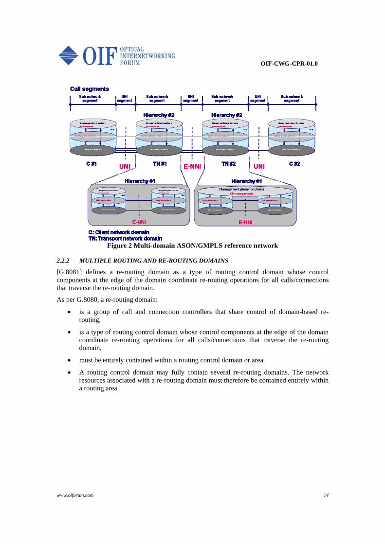
The reference network model covers multiple network domain scenarios (including multiple network layers, see section 2.4) at the client and network side (Figure 2) based on the following principles and assumptions.
Management plane
Data plane
CONTROL PLANE
DCN/SCN
CP MANAGEMENT
Management plane
Data plane
CONTROL PLANE
DCN/SCN
CP MANAGEMENT
OIF-CWG-CPR-01.0
www.oiforum.com 13
The reference network includes the following principles and basic assumptions:
Partitioning of the overall network in individual, independent network domains, separated by distinct demarcation points (G.805, section 5.3.2). o Network domains are interconnected by data and control plane interfaces supporting
this individuality per domain (User-Network and External Network-Network Interfaces; UNI and E-NNI). This implies that no node is shared among different domains (G.805, section 5.3.2.1).
o No specific management plane inter-domain relationship or association is assumed. o Support for call segmentation, allowing in each domain different flavors of
implementation and technologies. o One-to-one mapping of signaling and data channels is not implied for any inter-
domain interfaces (e.g., allow signaling channel association with multiple data channels).
Information exchanges between network domains across E-NNI shall be driven by local policy2.
Reachability information exchanges across inter-domain interfaces (UNI, E-NNI) shall be based on TNA reachability and subject to in-effect policies for the specific reference point.
Support for discovery mechanisms across E-NNI and UNI to ease operation of multiple domain networks and related calls and connections and subject to in-effect policies for the specific reference point.
Support for multiple hierarchies per network domain.
Allowing for independent allocation and physical distribution of functional components of the management, control and data plane (e.g., centralized versus distributed).
2 In-effect policy at a specific reference point is driven by local policy, subject to business/regulatory agreements and it will affect information exchanges and functionality available at this specific reference point.
OIF-CWG-CPR-01.0
www.oiforum.com 14
Figure 2 Multi-domain ASON/GMPLS reference network
2.2.2 MULTIPLE ROUTING AND RE-ROUTING DOMAINS
[G.8081] defines a re-routing domain as a type of routing control domain whose control components at the edge of the domain coordinate re-routing operations for all calls/connections that traverse the re-routing domain.
As per G.8080, a re-routing domain:
is a group of call and connection controllers that share control of domain-based re-routing,
is a type of routing control domain whose control components at the edge of the domain coordinate re-routing operations for all calls/connections that traverse the re-routing domain,
must be entirely contained within a routing control domain or area.
A routing control domain may fully contain several re-routing domains. The network resources associated with a re-routing domain must therefore be contained entirely within a routing area.
OIF-CWG-CPR-01.0
www.oiforum.com 15
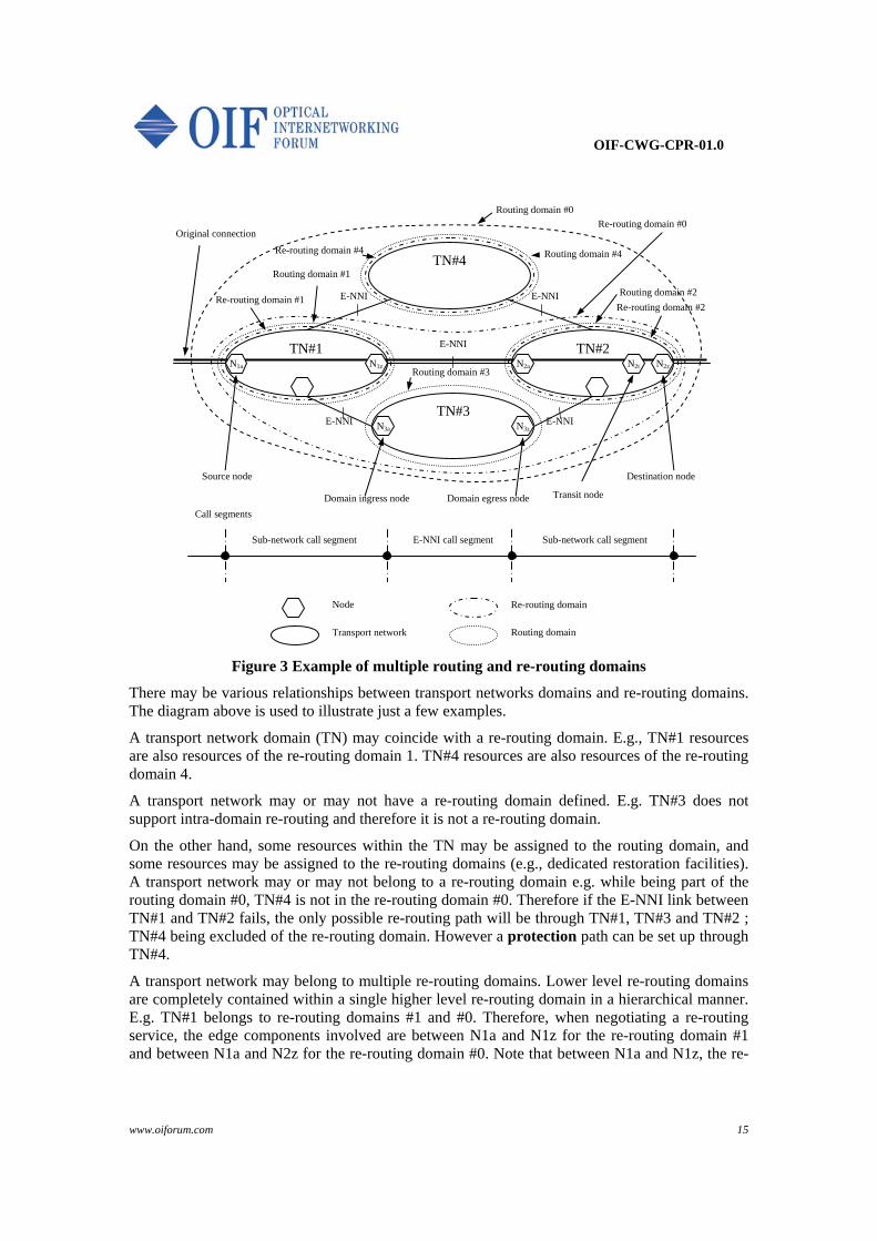
Figure 3 Example of multiple routing and re-routing domains
There may be various relationships between transport networks domains and re-routing domains. The diagram above is used to illustrate just a few examples.
A transport network domain (TN) may coincide with a re-routing domain. E.g., TN#1 resources are also resources of the re-routing domain 1. TN#4 resources are also resources of the re-routing domain 4.
A transport network may or may not have a re-routing domain defined. E.g. TN#3 does not support intra-domain re-routing and therefore it is not a re-routing domain.
On the other hand, some resources within the TN may be assigned to the routing domain, and some resources may be assigned to the re-routing domains (e.g., dedicated restoration facilities). A transport network may or may not belong to a re-routing domain e.g. while being part of the routing domain #0, TN#4 is not in the re-routing domain #0. Therefore if the E-NNI link between TN#1 and TN#2 fails, the only possible re-routing path will be through TN#1, TN#3 and TN#2 ; TN#4 being excluded of the re-routing domain. However a protection path can be set up through TN#4.
A transport network may belong to multiple re-routing domains. Lower level re-routing domains are completely contained within a single higher level re-routing domain in a hierarchical manner. E.g. TN#1 belongs to re-routing domains #1 and #0. Therefore, when negotiating a re-routing service, the edge components involved are between N1a and N1z for the re-routing domain #1 and between N1a and N2z for the re-routing domain #0. Note that between N1a and N1z, the re-
TN#2 TN#1
TN#3
TN#4
E-NNI
E-NNI E-NNI
E-NNI E-NNI N3zN3a
Routing domain #0
Routing domain #1
Re-routing domain #1
N1a N2z N1z N2a
Source node Destination node
Original connection
Call segments
Sub-network call segment Sub-network call segment E-NNI call segment
N2t
Transit node Domain ingress node Domain egress node
Node
Transport network Routing domain
Re-routing domain
Routing domain #3
Routing domain #4 Re-routing domain #4
Routing domain #2
Re-routing domain #0
Re-routing domain #2

OIF-CWG-CPR-01.0
www.oiforum.com 16
routing action is at the sub-network call segment, whereas between N1a and N2z, the re-routing action is from end-to-end.
2.3 Application of control plane proxy servers
On the roadmap towards an overall control plane enabled network scenario, ASON/GMPLS control plane proxy servers are of highest importance. The proxy servers are assigned for providing ASON/GMPLS control plane functions on behalf of client or network domains, at the established network reference points (Figure 4). The proxy servers support control plane information exchanges at either UNI or E-NNI interfaces. In addition, the proxy servers may also communicate with the management plane and/or data plane.
In this document no assumptions are made on the implementation of proxy servers. However, it is assumed that UNI and E-NNI information flows are supported, as appropriate. There may be different proxy server implementations. Proxy servers may be centralized, with one or multiple servers supporting a domain, or may be distributed with one or more proxy servers supporting individual data plane entities or network elements.
Figure 4 Multi-domain ASON/GMPLS reference network including control plane proxy server roles
2.4 Multi-layer network models
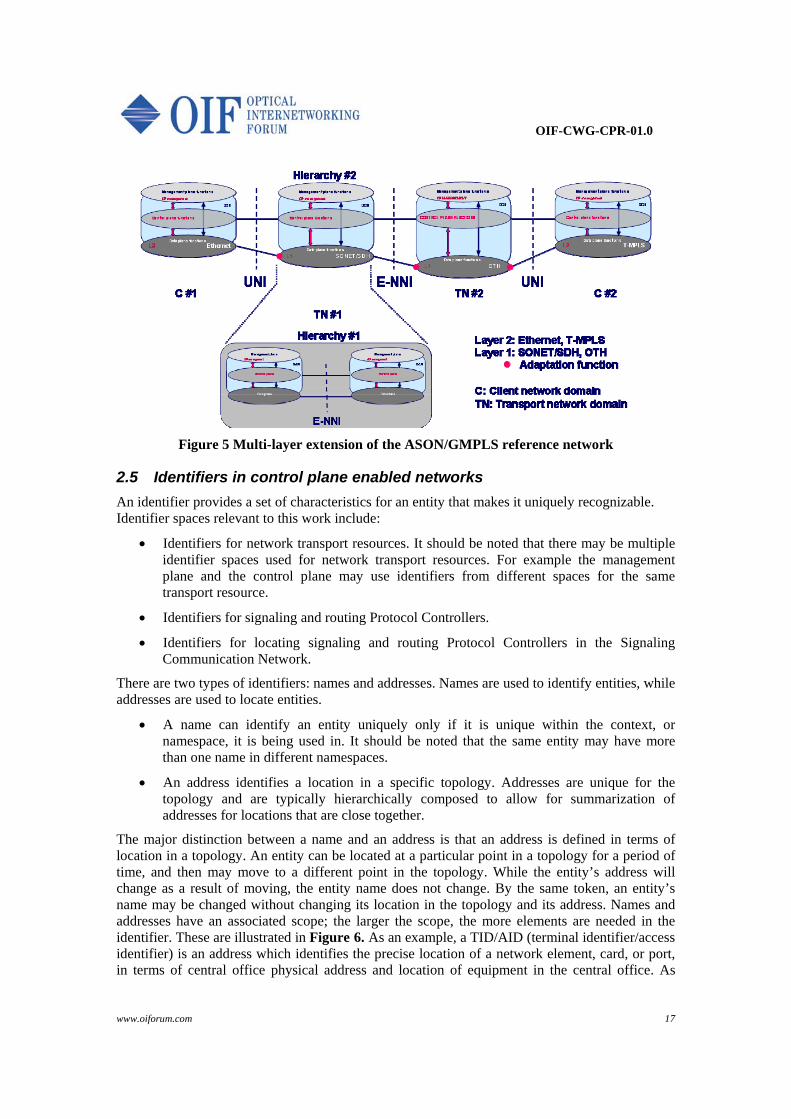
The reference network model may also be extended to a multi-layer and multi-domain network scenario, as depicted in Figure 5.
For this document, the adaptation functions between layers are assumed at the edge nodes of the lower order layers, enabling individual selection of technologies and platforms per domain. This means, e.g. that the E-NNI information exchanges at a given layer shall be agnostic to the underlying layer technology chosen in a particular domain.
OIF-CWG-CPR-01.0
www.oiforum.com 17
Figure 5 Multi-layer extension of the ASON/GMPLS reference network
2.5 Identifiers in control plane enabled networks
An identifier provides a set of characteristics for an entity that makes it uniquely recognizable. Identifier spaces relevant to this work include:
Identifiers for network transport resources. It should be noted that there may be multiple identifier spaces used for network transport resources. For example the management plane and the control plane may use identifiers from different spaces for the same transport resource.
Identifiers for signaling and routing Protocol Controllers.
Identifiers for locating signaling and routing Protocol Controllers in the Signaling Communication Network.
There are two types of identifiers: names and addresses. Names are used to identify entities, while addresses are used to locate entities.
A name can identify an entity uniquely only if it is unique within the context, or namespace, it is being used in. It should be noted that the same entity may have more than one name in different namespaces.
An address identifies a location in a specific topology. Addresses are unique for the topology and are typically hierarchically composed to allow for summarization of addresses for locations that are close together.
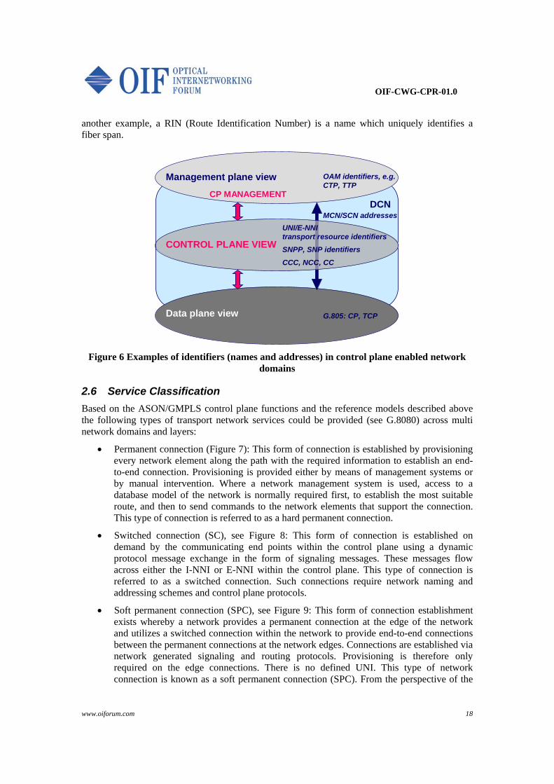
The major distinction between a name and an address is that an address is defined in terms of location in a topology. An entity can be located at a particular point in a topology for a period of time, and then may move to a different point in the topology. While the entity’s address will change as a result of moving, the entity name does not change. By the same token, an entity’s name may be changed without changing its location in the topology and its address. Names and addresses have an associated scope; the larger the scope, the more elements are needed in the identifier. These are illustrated in Figure 6. As an example, a TID/AID (terminal identifier/access identifier) is an address which identifies the precise location of a network element, card, or port, in terms of central office physical address and location of equipment in the central office. As
OIF-CWG-CPR-01.0
www.oiforum.com 18
another example, a RIN (Route Identification Number) is a name which uniquely identifies a fiber span.
Management plane view
Data plane view
CONTROL PLANE VIEW
DCNCP MANAGEMENT
MCN/SCN addresses
OAM identifiers, e.g.CTP, TTP
UNI/E-NNI transport resource identifiers
SNPP, SNP identifiers
CCC, NCC, CC
G.805: CP, TCP
Figure 6 Examples of identifiers (names and addresses) in control plane enabled network domains
2.6 Service Classification
Based on the ASON/GMPLS control plane functions and the reference models described above the following types of transport network services could be provided (see G.8080) across multi network domains and layers:
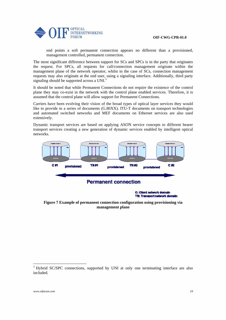
Permanent connection (Figure 7): This form of connection is established by provisioning every network element along the path with the required information to establish an end-to-end connection. Provisioning is provided either by means of management systems or by manual intervention. Where a network management system is used, access to a database model of the network is normally required first, to establish the most suitable route, and then to send commands to the network elements that support the connection. This type of connection is referred to as a hard permanent connection.
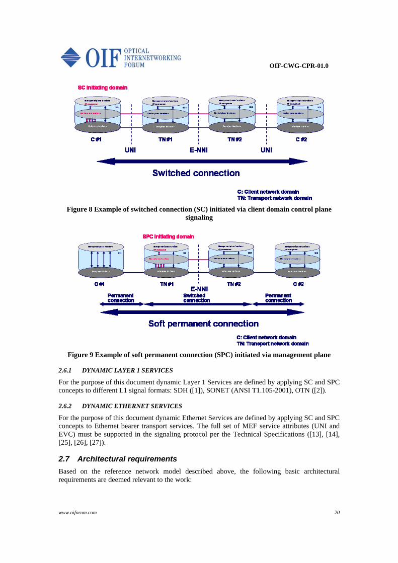
Switched connection (SC), see Figure 8: This form of connection is established on demand by the communicating end points within the control plane using a dynamic protocol message exchange in the form of signaling messages. These messages flow across either the I-NNI or E-NNI within the control plane. This type of connection is referred to as a switched connection. Such connections require network naming and addressing schemes and control plane protocols.
Soft permanent connection (SPC), see Figure 9: This form of connection establishment exists whereby a network provides a permanent connection at the edge of the network and utilizes a switched connection within the network to provide end-to-end connections between the permanent connections at the network edges. Connections are established via network generated signaling and routing protocols. Provisioning is therefore only required on the edge connections. There is no defined UNI. This type of network connection is known as a soft permanent connection (SPC). From the perspective of the
OIF-CWG-CPR-01.0
www.oiforum.com 19
end points a soft permanent connection appears no different than a provisioned, management controlled, permanent connection.
The most significant difference between support for SCs and SPCs is in the party that originates the request. For SPCs, all requests for call/connection management originate within the management plane of the network operator, whilst in the case of SCs, connection management requests may also originate at the end user, using a signaling interface. Additionally, third party signaling should be supported across a UNI.3
It should be noted that while Permanent Connections do not require the existence of the control plane they may co-exist in the network with the control plane enabled services. Therefore, it is assumed that the control plane will allow support for Permanent Connections.
Carriers have been evolving their vision of the broad types of optical layer services they would like to provide in a series of documents (G.80XX). ITU-T documents on transport technologies and automated switched networks and MEF documents on Ethernet services are also used extensively.
Dynamic transport services are based on applying ASON service concepts to different bearer transport services creating a new generation of dynamic services enabled by intelligent optical networks.
Figure 7 Example of permanent connection configuration using provisioning via management plane
3 Hybrid SC/SPC connections, supported by UNI at only one terminating interface are also included.
OIF-CWG-CPR-01.0
www.oiforum.com 20
Figure 8 Example of switched connection (SC) initiated via client domain control plane signaling
Figure 9 Example of soft permanent connection (SPC) initiated via management plane
2.6.1 DYNAMIC LAYER 1 SERVICES
For the purpose of this document dynamic Layer 1 Services are defined by applying SC and SPC concepts to different L1 signal formats: SDH ( [1]), SONET (ANSI T1.105-2001), OTN ( [2]).
2.6.2 DYNAMIC ETHERNET SERVICES
For the purpose of this document dynamic Ethernet Services are defined by applying SC and SPC concepts to Ethernet bearer transport services. The full set of MEF service attributes (UNI and EVC) must be supported in the signaling protocol per the Technical Specifications ( [13], [14], [25], [26], [27]).
2.7 Architectural requirements
Based on the reference network model described above, the following basic architectural requirements are deemed relevant to the work:

OIF-CWG-CPR-01.0
www.oiforum.com 21
R 1 The border nodes shall not be shared among transport domains, and the control plane shall support network domain partitioning as of G.805 (section 5.3.2).
R 2 Neither the signaling nor the routing protocols shall assume that any node in the transport network must belong to more than one domain at the same layer or at the same hierarchical level. (G.805, section 5.3.2.1).
R 3 The control plane shall support networks adhering to layering principles as of G.805 (section 5.3.3).
R 4 The control plane shall allow for independent allocation and distribution of functional components within the management, control and data plane (G.8080, section 5).
R.4.a The control plane should support one-to-N mapping of signaling to bearer channels at any inter-domain interfaces (e.g., allow signaling channel association with multiple data channels).
R 5 The control plane architecture, components and protocols shall not require and shall not assume congruence among the data, control and management plane components (G.8080, section 5).
R 6 The control plane shall support multiple hierarchies per domain (G.8080, section 6.2 and Appendix V).
R 7 The control plane shall support multi-domain call segmentation as per G.8080 (Section 6.7) and G.7713 (Ammendment1) (support for call segments and connection segments). Figure 2 Multi-domain ASON/GMPLS reference network depicts a pictorial of segmentation.
R 8 The control plane based UNI or E-NNI information exchanges (related to a given layer, e.g. Ethernet for UNI2.0 Ethernet) shall be agnostic to the layer technology chosen within the participating domain, (G.8080, section 8).
R 9 The control plane architecture, components and protocols shall not require that management plane functional components interface to each other across UNI or E-NNI (G.8080, annex A).
R 10 The following functional components are deemed important and should be supported by the control plane, subject to in effect policies.
R.10.a Automatic inter-domain discovery as per G.8080, section 6.3; G.7714. R.10.b Call and connection management per G.7713, section 10.
R 11 Signaling controllers, routing controllers and the data plane nodes shall not be assumed to be congruent.
R 12 Signaling communications network (SCN) and the data plane network shall not be assumed to be congruent.
R.12.a The SCN shall not be assumed to have the same physical connectivity as the data plane.
R.12.b The data plane and control plane traffic shall not be assumed to be congruently routed.
R.12.c The data plane and control plane components shall not be assumed to be congruent.
R 13 The control plane must support SCN topology change and underlying SCN transport technology modification (e.g., such as Ethernet, DCC OH, GCC OH, OSC) without affecting established connections.

OIF-CWG-CPR-01.0
www.oiforum.com 22
3 Control Plane Invocation Requirements Each of the services discussed has some specific requirements regarding service/activity invocation.
3.1 MANAGEMENT PLANE INVOCATION AND CONTROL
R 14 Connection management activities shall be invocable from the management plane. R.14.a Including set-up, release, query, re-routing or modification of SPC. R.14.b Including release, query, re-routing, or modification of SC.
R 15 The multi-domain control plane shall support requests from the management plane for either end-to-end, loose or explicit routing.
3.2 USER OR USER PROXY INVOCATION AND CONTROL (SC)
Guiding principle – it is the intent of this group to ensure that all service functionality supported over the UNI shall also be supported by the network.
R 16 All connection management activities, including set-up, release, query, or modification shall be invocable from a user edge device, or its signaling representative (such as a signaling proxy).
R 17 UNI-C requests at the client layer shall not include specifications for server layer implementation of functionality.
R 18 The transport network control plane shall support the mapping of the client layer requests to the appropriate server layer.
R 19 The control plane receiving a connection request from a user edge device, or its signaling representative (such as a signaling proxy) shall have the ability to forward all the relevant information to the management plane or to another control domain.
R 20 The control plane shall collect and forward to the management plane sufficient information about each connection to allow billing based on end points, service characteristics (e.g., bandwidth, format type, service class), customer identity, facilities traversed end-to-end, connect and disconnect times/dates.
Additional information on service invocation model and configuration can be found in section 7 of [28].
3.3 DATA PLANE INVOCATION AND CONTROL
R 21 Connection recovery activities shall be invocable from the data plane. R.21.a Including switching for protection purpose. R.21.b Including re-routing for restoration purpose.
OIF-CWG-CPR-01.0
www.oiforum.com 23
4 Identifier Requirements
4.1 IDENTIFIER SPACE SEPARATION
4.1.1 NAME SPACE SEPARATION
It is important that control plane implementations and their associated protocols do not place restrictions on the naming spaces used outside of the control plane, such as management plane naming spaces. It is further important that the control plane does not impose restrictions on the names used by other networks, except for the inter-connected resources.
R 22 It shall be possible to independently identify logically distinct entities; e.g., R.22.a Control plane name spaces shall be independent of transport resources name
spaces; R.22.b Control plane view name spaces shall be independent from management plane
view name spaces of the transport resources. R 23 Client transport resource name spaces shall be independent of carrier transport
resource name spaces, except for transport resource access points (e.g., inter-connecting resources) that are governed by in-effect policies.
R 24 Different carrier transport resource names may be independent from one another except for transport resource access points (e.g., inter-connecting resources) that are governed by in-effect policies.
R 25 The inter-domain protocols (i.e., UNI, E-NNI) shall not mandate revealing control plane view names for transport resources externally, outside of a carrier network boundaries, except for transport resource access points (e.g., inter-connecting resources)that are governed by in-effect policies.
R.25.a Clients shall not inherently have visibility to carrier transport resource names and other information (such as detailed node information, network topology, etc), except for transport resource access points (e.g., inter-connecting resources) that are governed by in-effect policies.
R.25.b Other transport carriers shall not be able to obtain knowledge of carrier transport resource names (such as detailed node information, network topology, etc), from information exchanged across an E-NNI except for transport resource access points (e.g., inter-connecting resources) that are governed by in-effect policies.
R 26 The inter-domain protocols (i.e., UNI, E-NNI) shall not mandate revealing management plane names or management plane views of the transport network resources.
R 27 The inter-domain protocols (i.e., UNI, E-NNI) shall not mandate revealing management plane views of control plane components externally, outside of carrier network boundaries.
R 28 Carrier signaling access points (or proxies) may be assigned names that are available to customers to identify endpoints in call/connection requests.
R 29 Carrier signaling access points (or proxies) may be assigned names that are available to other carriers to identify inter-carrier segments in call/connection requests.
OIF-CWG-CPR-01.0
www.oiforum.com 24
4.1.2 ADDRESS SPACE SEPARATION
R 30 Control plane components address space is independent of transport resources address space
R.30.a SCN address space shall be independent of Data Plane Resource address space (e.g., support of proxies)
R 31 The control plane architecture, component, and protocols shall assume that client transport resource address space is independent of carrier transport resource address space.
R 32 The control plane architecture, component, and protocols shall assume that different carrier transport resource address spaces are independent from one another.
R 33 The inter-domain protocols (i.e., UNI, E-NNI) shall not mandate revealing transport network addresses externally, outside of a carrier network boundaries except for transport resource access points (e.g., inter-connecting resources) that are governed by in-effect policies.
R.33.a Clients shall not inherently have visibility to carrier transport resource addresses and other information (such as detailed node information, network topology, etc), except for transport resource access points (e.g., inter-connecting resources) that are governed by in-effect policies.
R.33.b Other transport carriers shall not be able to obtain knowledge of carrier transport resource addresses (such as detailed node information, network topology, etc), from information exchanged across an E-NNI except for transport resource access points (e.g., inter-connecting resources) that are governed by in-effect policies.
R 34 The inter-domain protocols (i.e., UNI, E-NNI) shall not mandate revealing management plane addresses.
R 35 The inter-domain protocols (i.e., UNI E-NNI) shall not mandate revealing control plane addresses (SCN addresses) externally, outside of carrier network boundaries, except for transport resource access points (e.g., inter-connecting resources) that are governed by in-effect policies.
R 36 Carrier signaling access points (or proxies) may be assigned addresses that are available to customers to identify endpoints in call/connection requests.
R 37 Carrier signaling access points (or proxies) may be assigned addresses that are available to other carriers to identify inter-carrier segments in call/connection requests.
4.1.3 NAME – ADDRESS SEPARATION
R 38 Name spaces used to identify the network resources shall be independent of address spaces used to locate the network resources (e.g., data plane, control plane, management plane resources).
R 39 It shall be possible to translate between transport resource access point names and carrier transport resource addresses.
R.39.a Directory Services shall be supported. R.39.b Address Translation between user edge device naming, network addressing, and
physical entity naming shall be supported.

OIF-CWG-CPR-01.0
www.oiforum.com 25
4.2 ADDITIONAL IDENTIFIER REQUIREMENTS
R 40 The control plane may support independent address spaces at different layers consistent with operator policy.
R 41 Addressing hierarchies shall be supported. R 42 Address aggregation and summarization shall be supported.4 R 43 The size of the address space shall be sufficient to avoid address exhaustion. It is
desirable to have support for 128 bits or higher address length hierarchies. R 44 TNA reachability deals with connectivity and shall not be changed when the user
device is not available (reachability updates are triggered by registration and deregistration, not by client device reboots) (Name registration persists for as long as the user retains the same TNA – until de-registration).
4 This actually is an E-NNI requirement
OIF-CWG-CPR-01.0
www.oiforum.com 26
5 Call and Connection Management Requirements This section addresses call management and connection management requirements. The following actions must be supported by the control plane:
Set-up
Release
Call Modification
Attribute modification
Query of attributes
Connection re-routing (e.g., for restoration or for network optimization)
This section addresses individual connection management actions and their related requirements.
R 45 Control plane signaling mechanisms and flows shall comply with G.8080 and G.7713 (ITU).
R 46 Inter-domain protocols shall support call and connection segmentation consistent with the reference architecture and G.8080.
R 47 The UNI signaling protocol shall be agnostic to the intra-domain signaling protocol within any of the domains within the network or to the inter-domain signaling protocols.
R 48 UNI signaling protocols shall be agnostic of the E-NNI signaling protocols. R 49 UNI signaling shall allow for different UNI signaling protocols at the edges of the
calls. R.49.a shall allow for clients using different protocols at the UNI. R.49.b shall allow for single ended signaling (only one end has UNI, the other end is
controlled by the management plane). R 50 UNI signaling shall allow for lack of signaling protocols within the network domain
(support of UNI-N proxy). R 51 The E-NNI signaling protocol shall be agnostic to the intra-domain signaling protocol
within any of the domains within the network. R 52 E-NNI signaling shall be agnostic of the UNI signaling. R 53 E-NNI signaling shall allow for lack of UNI signaling protocols at the edges of the
connections (i.e., shall not be dependent on client devices at both edges of the connections support of the UNI signaling – support of UNI-C proxy and of management plane invocation).
R 54 E-NNI signaling shall support both strict and loose routing set-up requests. R 55 Control plane signaling shall support all call management actions:
R.55.a Call Set-up. R.55.b Call Release. R.55.c Call Modification (add connection(s), remove connection(s), change (allowable)
attributes, etc.) (see Section 5.5 Modification). R.55.d Call Queries.
R 56 Control plane signaling shall support all connection management actions: R.56.a Per individual connections. R.56.b Per groups of connections.
OIF-CWG-CPR-01.0
www.oiforum.com 27
R 57 The control plane shall support per call global call identifier for all call management actions within a carrier’s network.
R 58 The control plane shall support per connection global connection identifier for all connection management actions within a carrier’s network.
R 59 The control plane shall support both positive and negative responses for all requests, including the cause, when applicable.
R 60 Inter-domain signaling shall support all the connection attributes representative of the connection characteristics of the individual connections in scope.
5.1 CONNECTION CHARACTERISTICS
It is the intention of this section to address support of connection characteristics consistently with the inter domain UNI & E-NNI interfaces required functionality.
R 61 Granularity: The control plane shall support signaling and routing functions for all dynamically controlled layers.
R 62 Adaptation: The control plane shall support signaling and routing for all adaptation functions supported by the data plane (e.g., Ethernet over SONET/SDH, Ethernet over OTN, etc).
R 63 Interworking: The control plane shall allow data plane interworking between domains using different adaptation functions and underlying server layers in support of the same client layers.
R 64 Connection topology: The control plane shall support signaling and routing functions for point-to-point calls and their associated connections.
R 65 Connection topology: The control plane should support signaling and routing functions for point-to-multipoint calls and their associated connections (unicast and/or multicast) as supported by the data plane.
5.2 NOMINAL PATH
R 66 It shall be possible to assign a Nominal Path to a connection. R 67 It shall be possible to designate the Current Path as a Nominal Path. R 68 It shall be possible to request that the network provide a Nominal Path (at connection
set-up). R 69 It shall be possible to request that a specific, explicit path is used as a Nominal Path
for a connection. R 70 It shall be possible to request to change the Nominal Path to a new Nominal Path. R 71 The Nominal Path resources shall be maintained, consistent with operator policy.
5.3 SET UP
This section should include set-up of calls with any number of connections. Also, it should include support for constraint based routing (e.g., request for diverse connections).
The result of connection set-up is a connection with specified attributes (by a user, policy manager, or other OSS) established between two or more end-points. The following requirements apply to connection set-up.
R 72 The Control Plane shall support request for call set-up across multiple domains.
OIF-CWG-CPR-01.0
www.oiforum.com 28
R 73 Upon call set-up initiation the control plane shall assign a call identifier associated with the call, to be used for information retrieval or other activities associated with the call (e.g., call release, call modification, connection addition or deletion, etc.).
R 74 The Control Plane shall support requests for call set-up, subject to policies in effect. R 75 The call set-up request shall be allowed to include requests for one or more associated
connections. R.75.a Bi-directional connections. R.75.b Uni-directional connections. R.75.c Asymmetric bi-directional connections.
R 76 The call set-up request should be allowed to include requests for one or more associated connections:
R.76.a Uni-directional broadcast tree. R.76.b Uni-directional multicast tree.
R 77 For each connection request, the control plane shall generate a network unique connection identifier associated with each connection, to be used for information retrieval or other activities related to that connection.
R 78 Connection set-up shall be treated as a potentially billable event and the control plane shall pass all the relevant information to the management plane.
R 79 The Management Plane should be able to retrieve information details from the Control Plane about network resources associated to a particular Call-ID/Connection-ID.
R 80 The Management Plane should be able to retrieve from the Control Plane the Call-ID/Connection-ID associated to any allocated network resources.
R 81 The Control Plane shall have the ability to identify the network resources in use, per G.8080 binding states (busy, potential, allocated, shutting down, released).
R 82 Call Admission Control shall be provided as part of the control plane functionality. It is the role of the Call Admission Control function to determine if the call may proceed between source and destination, across multiple domains, within the established policies, before the call is established.
R 83 The Control Plane shall have the ability to determine the service level associated to network resources in use per G.8080 binding states, as appropriate.
R 84 Connection Admission Control shall be provided as part of the control plane functionality. It is the role of the Connection Admission Control function to determine if there are sufficient resources in the network/domain to be allocated to the requested connection, within the established policies.
R 85 If there is sufficient resource available, the Connection Admission Control may permit the connection request to proceed.
R 86 If there is not sufficient resource available, the Connection Admission Control shall send an appropriate notification upstream towards the originator of the connection request that the request has been denied.
R 87 The Control Plane shall support contention resolution mechanisms. More detailed requirements can be found in Section 7.2.4.
R 88 The Control Plane shall support multiple service level options, which may be different across multiple domains. Individual service level routing constraints shall be governed by carrier policies.
R 89 The Control Plane shall be able to assign appropriate resources to connections. R 90 The Control Plane shall recognize congestion within the data plane and the Signaling
Communication Network (SCN). R 91 The Control Plane should limit call and connection setup attempts during congestion.

OIF-CWG-CPR-01.0
www.oiforum.com 29
R 92 The Control Plane shall report to the management plane, the Success/Failure of a call or a connection request.
R 93 Upon a call set-up / connection request success: R.93.a The control plane shall report success to the management plane. R.93.b A positive acknowledgment shall be returned to the requesting entity.
R 94 Upon a call or connection set-up request failure: R.94.a The control plane shall report to the management plane a cause code(s)
identifying the reason for the failure. The cause code shall have sufficient information to allow corrective action if needed, (e.g. resource limits).
R.94.b A negative acknowledgment with appropriate error codes shall be returned to the requesting entity.
R.94.c All resources associated with the failed attempt shall be released. R 95 The Control Plane shall keep track of call / connection set-up request failures and the
reason for the failures. The Control Plane shall provide this information to the management plane.
R 96 It is the Control Plane responsibility to identify and track partial connections in the network as a result of unsuccessful call or connection set-up attempts. There shall not be any partial connections left in the network as a result of unsuccessful set-up attempts. If some resources cannot be released, the Control Plane shall notify the Management Plane.
5.4 RELEASE
R 97 The control plane shall support requests for call release (tear down). Call release shall be construed as releasing all connections associated with a call and releasing all the resources used by those connections.
R 98 The control plane shall allow the management plane to initiate call release procedures on any call, regardless of how the call was established.
R 99 For switched calls (switched connection services), the control plane shall allow either end to initiate call release procedures.
R 100 If all the connections associated with a call have been released, the control plane shall allow that the call be released or that the call be maintained without supporting connections, in accordance with in-effect policy.
R 101 The Control Plane shall support requests for connection release: R.101.a As an explicit connection release request. R.101.b As part of call modification or call release request.
R 102 The Control Plane shall be able to release a connection without affecting the Call State.
R 103 Inter-domain signaling shall support graceful deletion of calls including of failed calls, if needed.
R 104 Inter-domain signaling shall support graceful deletion of connections including of failed connections, if needed.
R 105 The control plane shall allow the management plane to initiate connection release procedures on any connection, regardless of how the connection was established.
R 106 The control plane shall allow any end point or any intermediate node to initiate the connection release procedure.
R 107 Upon connection release completion all resources associated with the connection shall be released.
OIF-CWG-CPR-01.0
www.oiforum.com 30
R 108 The Control Plane shall identify any partial connections left in the network as a result of unsuccessful release attempts.
R 109 Partially deleted connections shall not remain within the network. If the control plane is not able to remove partial connections from the network, it shall notify the management plane of its failure to do so, identifying all resources associated with the partial connections.
R 110 Acknowledgments shall be used for connection deletion requests. R 111 Connection deletion shall not result in either restoration or protection being initiated. R 112 In case of any release failure, the Control Plane shall notify the Management Plane.
5.5 MODIFICATION
This section addresses call and connection modification: Call modification refers to modification of specific call attributes of an established call.
Currently call modification refers to the operation of adding or removing connections to an existing call.
Connection modification refers to modification of specific connection attributes of an established connection.
It is important that any attribute modification does not cause service or network disruption or degradation. This limits modification to exclude attributes such as encoding type, transparency, logical port identifier, or end-points. Modifiable attributes include bandwidth (i.e. by adding or removing connections to the call), service class, and restoration priority.
R 113 The following call modification procedures shall be supported: R.113.a Add connection. R.113.b Remove connection.
R 114 Call modification procedures shall be supported within Call Admission Control in-effect policies.
R 115 The control plane shall support requests for connections set-up as part of call modification procedure (addition of connections to an existing call).
R 116 Connection addition shall follow connection set-up procedures. R 117 The control plane shall support requests for connections removal as part of call
modification procedure (removal of connections from an existing call). R 118 Connection removal shall follow connection release procedures. R 119 Only non-destructive connection attribute modification should be provided by the
Control Plane, subject to in-effect policies. R 120 Modification of any connection attribute shall be supported as a network configurable
action, subject to established policies and SLAs. R 121 Attribute modification shall not cause failure of the call or connection. R 122 The control plane shall report to the management plane, the Success/Failures of a
connection modification request. R 123 Upon a connection modification failure:
R.123.a The control plane shall report to the management plane a cause code identifying the reason for the failure.
R.123.b A negative acknowledgment shall be returned. R.123.c Allocated resources for the connection modification procedure shall be released. R.123.d The call and its associated connections, established prior to the failed
modification procedure, shall maintain their initial attributes. R 124 Upon a connection modification success a positive acknowledgment shall be returned.
OIF-CWG-CPR-01.0
www.oiforum.com 31
R 125 Attribute modification shall not result in protection or restoration being initiated within an optical transport network.
R 126 Attribute modification shall be treated as a service offered by an optical transport network. Service discovery protocol shall support the capability to discover a network’s support for attribute modification, subject to in effect policies at the specific reference point.
R 127 Attribute modification shall be treated as a potentially billable event and the control plane shall pass all the relevant information to the management plane.
5.6 QUERIES
This section contains requirements related to specific connection related queries.
R 128 The control plane shall at a minimum maintain the current state for each of the following items:
R.128.a Calls under its control. R.128.b Connections under its control.
R 129 The control plane shall support management plane and neighboring device (client or intermediate node) request for call / connection attributes or status query.
R 130 The control plane shall support action results code responses to any query requests over the control interfaces.
5.7 CONNECTION ROUTING AND PATH COMPUTATION
R 131 The inter-domain routing protocol shall comply with G.8080 and G.7715. R 132 The inter-domain routing protocol shall be agnostic to the intra-domain routing
protocol within any of the domains within the network. R 133 The control plane shall allow any of the following routing paradigms within individual
domains: R.133.a Hierarchical routing. R.133.b Domain-by-domain routing. R.133.c Source routing.
R 134 The control plane shall allow use of traffic engineering paradigms within individual domains, such as:
R.134.a Cost. R.134.b Load sharing.
R 135 The control plane shall allow the exchange of the following types of information by inter-domain routing protocols, subject to policy constraints:
R.135.a Inter-domain topology. R.135.b Per-domain topology abstraction. R.135.c Per domain reachability information. R.135.d Path computation information.
R 136 The control plane may not require that network related information be shared with other networks unless allowed by local in-effect policy.
R 137 The control plane shall allow TNA reachability information exchange and aggregation based on in-effect policies at the specific reference point.
R 138 The control plane shall allow TNA<->address translation within individual domains. R 139 Routing algorithms used for transport networks shall include support of multiple points
of interconnection between two domains.

OIF-CWG-CPR-01.0
www.oiforum.com 32
R 140 The control plane shall allow path computation within a domain and/or across multiple domains by various constraints, such as:
R.140.a Include / exclude resources R.140.b Diversity5 . This means that the control plane must provide a mechanism to
compute fully diverse paths. R.140.c Service class.
5.8 ADMINISTRATIVE CONNECTION RE-ROUTING
Administrative re-routing is initiated by the management plane. Connection re-routing is a special case of Call Modification and it refers to modification of the route used for a specific connection of an established call. Currently connection re-routing is only considered as a management plane initiated operation.
Instances which may prompt a carrier to require re-routing include Planned Maintenance Activities (PMAs), network re-optimizations, etc.
R 141 It should be possible to request re-routing of connections from the management plane even without the presence of a failure in the network.
R 142 Administrative re-routing shall support re-routing of the Current Path. R 143 Administrative re-routing shall support routing constraints (e.g., include/exclude
resources, diverse paths, etc) in accordance with the in-effect policies for the administrative domains
R 144 Administrative re-routing shall not change other connection attributes, (e.g. existing class of service, restorability or restoration priority).
R 145 For administrative re-routing the original connection is not taken out of service until the rerouted connection is established (hitless re-routing).
R 146 For any administrative re-routing, the rerouted connections shall continue to use the same border end-points (domain ingress and egress SNPPs) in the administrative domain.
Notes: 1. Administrative re-routing may be used to replace the nominal path with a different nominal
path, (e.g. to support activities such as network or connection optimization). In this case the Nominal Path of the connection may be changed to the re-routed path.
2. Administrative re-routing may also be used for a temporary re-route in support of PMAs. In this case only the current path will be changed and the connection will revert to its original Nominal Path upon completion of the PMA.
3. Links affected by PMAs may need to be taken out of the CP inventory.
R 147 Connection re-routing procedures shall be supported within Call Admission Control in-effect policies.
R 148 Connection re-routing shall be hitless. R 149 Connection re-routing shall support both revertive and non-revertive behavior
(Specific requirements on reversion are in section 6.3.3). R 150 Connection re-routing shall be supported as a network configurable action, subject to
established policies and SLAs. R 151 Successful connection re-routing shall not cause failure of the call.
5 Link, node and SRG diversity should be considered
OIF-CWG-CPR-01.0
www.oiforum.com 33
R 152 The control plane shall report to the management plane, the Success/Failures of a connection re-routing request.
R 153 Upon a connection re-routing failure: R.153.a The control plane shall report to the management plane a cause code identifying
the reason for the failure. R.153.b A negative acknowledgment shall be returned. R.153.c Allocated resources for the connection modification procedure shall be released. R.153.d The Call and its associated Connections, established prior to the failed
modification procedure, shall maintain their initial attributes. R 154 Upon a connection re-routing success:
R.154.a A positive acknowledgment shall be returned. R.154.b The new connection route shall be recorded appropriately.
R 155 Connection re-routing shall not result in protection or restoration being initiated within an optical transport network.
OIF-CWG-CPR-01.0
www.oiforum.com 34
6 Service Resilience This section addresses control plane and service resilience.
Service Resilience refers to the ability of the network to continue supporting services without disruptions after control plane or data plane failures. It should be noted that only certain aspects of service support are required during control plane failures.
6.1 SERVICE RESILIENCE OPTIONS
We use “service level” to describe, service resilience options such as availability, recovery time (such as 50 ms, 200 ms, sub-second, etc.), or priority related characteristics of connections (such as holding priority, set-up priority, or restoration priority). The intent is to allow each carrier to define the actual service levels within their individual service offerings. Therefore, mapping of individual service levels to a specific set of connections attributes and/or routing constraints will be determined by individual carriers.
R 156 The control plane shall support multiple service resilience level options. R 157 The control plane shall allow requests for different service resilience level options on a
per call basis. R 158 The control plane shall identify, assign, and track network resources supporting
multiple service level resilience options. R 159 The Control Plane shall be able to map service level requests to the appropriate
network resources and attributes in each control domain to ensure the requested end to end service level.
R 160 If the Control Plane is not able to provide the requested service level it may propose an alternative service level.
6.1.1 CONTROL PLANE RESILIENCE
Control Plane Resilience refers to the ability of the control plane to continue operations under failure conditions and to recover from control plane failures. It should be noted that the control plane may not be able to recover or continue operations for all failure conditions. However, the control plane should be designed to handle most common occurrences of failures.
Common occurrences of failures may include (this is not an exhaustive list):
Signaling/control channel failure.
Control plane component failure.
R 161 The control plane shall provide reliable transfer of signaling messages and flow control mechanisms for restricting the transmission of signaling messages where appropriate.
R 162 Control plane must be able to recover from any control plane components failures. R 163 The control plane shall be capable of operating in network environments where the
data plane has underlying recovery capability. R 164 The control plane shall not be degraded by data plane or management plane failures. R 165 The control plane should support options to enable it to be self-healing. R 166 Control plane failure detection mechanisms shall distinguish between control channel
and control plane components failures.
OIF-CWG-CPR-01.0
www.oiforum.com 35
R 167 Fault localization techniques for the isolation of failed control plane components (including signaling channels and software modules) shall be supported.
R 168 Recovery from control plane failures shall result in complete recovery of actual network state.
R.168.a Data plane, R.168.b Control plane, R.168.c Established calls and connections, R.168.d Up-to-date call and connection states [For connections whose states changed
during this failure (such as due to user request to teardown connection), the states of these connections must be synchronized.].
6.1.2 SERVICE RESILIENCE FOR CONTROL PLANE FAILURES AND DISRUPTIONS
R 169 The control plane shall ensure that no control plane component (software modules or control plane communications) represents a single point of failure.
R 170 Existing (established) calls and connections must not be affected by any failures (either hardware or software module, including even complete control plane failures) or by planned maintenance activities (e.g., such as control plane upgrades) within the control plane.
R 171 Existing (established) calls and connections shall not be affected (i.e., no service affecting interruptions) by signaling communications network (SCN) failures.
R 172 In the event a control plane failure occurs, recovery mechanisms shall be provided such that:
R.172.a Connections should not be left partially established as a result of a control plane failure.
R.172.b Connections affected by a control channel failure during the establishment process must be removed from the network, re-routed, or continued once the failure has been resolved.
R.172.c If partial connections are detected upon control plane recovery, then those partial connections shall be removed once the control plane is recovered.
R.172.d The control plane shall accurately track the resource allocation ensuring that there shall not be unusable network resources under its control.
R 173 The control plane shall provide the management plane with the information necessary for the determination of asset utilization, and shall support periodic and on demand clean-up of network resources.
R 174 The control plane shall ensure that signaling messages are routed around failure(s). R 175 Control plane failures shall not cause management plane or date plane degradation or
failures. R 176 If control plane communication is completely lost to a border node, or an
internetworking border node’s control plane fails: R.176.a Established connections shall not be affected. R.176.b The connected NE over an E-NNI shall realize it has lost its control
communication link to its counterpart and shall advertise within its control domain, that the E-NNI interface has failed.
R.176.c Connection management activities interrupted by the failure are handled per requirements in section 5.
R.176.d Appropriate alarms are issued and recovery of the control plane is handled per requirements in section 6.1.1.

OIF-CWG-CPR-01.0
www.oiforum.com 36
6.2 SERVICE RESILIENCE FOR DATA PLANE FAILURES AND DISRUPTIONS
This section discusses the role of the control plane in the data plane recovery process.
Both protection and restoration mechanisms are employed to support service resilience.
Protection aims at extremely fast reaction times and may rely on the use of overhead control fields for achieving end-point coordination. Protection mechanisms can be further classified by the level of redundancy and sharing.
Restoration mechanisms rely on signalling protocols to coordinate switching actions during recovery, and may involve simple re-provisioning, i.e. signalling only at the time of recovery; or pre-signalling, i.e., signalling prior to recovery. Restoration uses signaling after failure to allocate resources along the recovery path. The following restoration mechanisms are assumed within this document:
Shared-Mesh Restoration: Multiple protecting connections are allowed to share common link and node resources. The recovery resources for the protecting connections are PRE-RESERVED during the provisioning phase, thus an explicit signaling action is required to activate (i.e. commit resource allocation at the data plane) a specific protecting connection instantiated during the (pre)-provisioning phase. This requires restoration signalling along the protecting connection.
Connection Re-routing: Normal traffic is switched to an alternate connection that is fully established only after failure occurrence. The new (alternate) route is selected at the connection head-end and may reuse intermediate nodes included in the original route; it may also include additional intermediate nodes. The alternate route may be either:
o COMPUTED ON DEMAND (that is, when the failure occurs; this is referred to as FULL connection rerouting) or,
o PRE-COMPUTED and stored for use when the failure is reported.
Depending on the failure type, failure location, and operator preference, intra-domain or inter-domain (multi-domain or end-to-end) recovery may be appropriate. For each type of recovery, there are several steps that are required:
Failure detection.
Failure notification.
Recovery notification.
Recovery mechanisms.
6.2.1 FAILURE SCENARIOS
Figure 10 illustrates the different failure scenarios considered in this document:
Intra-domain failure.
Inter-domain link failure.
Border node failure.

OIF-CWG-CPR-01.0
www.oiforum.com 37
Figure 10 Example of inter-domain and intra-domain failures
Intra-Domain Failures
Intra-domain failures are any failures within a domain. Intra-domain recovery occurs in a domain and recovers a sub-network call/connection segment. There are recovery techniques such as intra-domain protection/restoration that can recover from the failure locally without the intervention of any external entities (E.g. node outside the domain, OSS). Intra-domain recovery mechanisms and details based solely on I-NNI signaling are not in scope for this document. It is assumed that intra-domain recovery does not change the nominal path of the multi-domain connection (the border end points of the domain where intra-domain recovery occurred are not changed).
Inter-domain failures
This section differentiates between two types of inter-domain failures: inter-domain link failures and border node failures. Each type is discussed below.
Inter-domain link failures
An inter-domain link failure will render its associated UNI or E-NNI link unavailable for data transfer. There are multiple options for recovery from an inter-domain link failure:
Locally at the UNI or E-NNI call/connection segment.
Inter-domain recovery across multiple domains including the associated UNI or E-NNI call/connection segments.
Border node failures
Border nodes are ingress and egress nodes for domains traversed by the call/connection(s) under consideration. Border node failure is assumed to be the failure of the entire node at the data plane (and possibly at the control plane). It affects all the UNI or E-NNI links attached to the node and makes them unavailable for data transfer. The recovery from border node failures involves bypassing the failed border node and the previously used attached UNI or E-NNI link(s) in the new path of the call/connection(s). Therefore, border node failures recovery happens at least at both the UNI or/and E-NNI and at the sub-network call/connection segments.
A B C
A B CIntra-domain failure Inter-domain link failure Border node failure
OIF-CWG-CPR-01.0
www.oiforum.com 38
6.2.2 CONTROL-PLANE BASED RECOVERY MECHANISMS
This section contains generic requirements for:
Intra-domain recovery aspects as they pertain to multi-domain resilience.
Inter-domain (multi-domain or end-to-end) recovery across multiple domains.
Call/connection segment recovery as it pertains to multi-domain resilience.
R 177 The control plane must provide the capability to support recovery of data plane node failures, e.g., route around a single data plane node failure.
R 178 The recovery mechanisms shall support recovery from single failures, as appropriate: R.178.a Intra-domain failures may be handled by intra-domain recovery within the
affected domain or by inter-domain (multi-domain or end-to-end) recovery. Intra-domain recovery should take precedence over other mechanisms for intra-domain failures.
R.178.b Inter-domain link failures may be handled by link protection or inter-domain recovery (multi-domain or end-to-end).
R.178.c Border node failure may be handled by inter-domain recovery (multi-domain or end-to-end).
R.178.d End-to-end recovery or re-provisioning may be used when other means of recovery fail.
R 179 The Control Plane shall allow autonomous intra-domain recovery with inter-domain coordination as appropriate.
R 180 The Control Plane shall allow inter-domain link failure recovery with inter-domain coordination, as appropriate.
R 181 The Control Plane shall allow border node failure recovery with inter-domain coordination, as appropriate.
R 182 The recovery mechanisms should support recovery from multiple failures. R 183 Control plane based recovery mechanisms shall provide functional solutions
independent of the underlying data plane technology (e.g., independent of the carried client signal format).
R 184 Control plane based recovery mechanisms shall address failures affecting multiple connections simultaneously. Bulk recovery mechanisms should be supported by the control plane.
R 185 All Control Plane based recovery mechanisms (including hard rerouting) shall support both revertive and non-revertive behaviors (see section 6.3.3).
R 186 An ongoing recovery process shall not be impeded by new connection set-up requests. R 187 Control plane based recovery mechanisms should include support for multiple levels of
recovery priorities. R 188 Connections, which are not recovered, shall be released or marked as failed according
to operator policy. R.188.a A mechanism shall exist to send notifications both upstream and downstream
that the connection cannot be recovered. R.188.b For connections marked as failed, the control plane shall maintain connection
state information until the failure is repaired. R 189 There shall not be any partial connections left in the network as a result of
unsuccessful recovery attempts. Mechanisms shall be supported to release network resources assigned to unsuccessful recovery attempts.
R 190 Normal connection operations shall not result in recovery mechanisms being initiated by the control plane.

OIF-CWG-CPR-01.0
www.oiforum.com 39
R 191 Multi-layer recovery mechanisms shall be coordinated so that: R.191.a The responsibility of each survivable layer may be delineated. R.191.b Assuming a failure may be first detected by the layer closer to the failure,
methods shall be provided to determine which recovery mechanism is to act first according to the type of failure and /or service affected. Escalation strategies (e.g., correlation) should be used to avoid having multiple layers respond to a single failure.
R 192 Both success and failure of recovery attempts shall be reported to the management plane.
6.2.3 INTRA-DOMAIN RECOVERY
Intra-domain control plane protocols are out of scope for this document. However, functional requirements and the relationship to the inter-domain protocols are considered in scope.
Intra-domain recovery may be used to recover from failures that do not affect domain border nodes or inter-domain links along the route of the connection.
Specific mechanisms for failure notification and sub-network segment recovery within the domain are outside the scope of this document. However, failure notification should be considered for multi-domain signaling when intra-domain recovery failed. If intra-domain recovery fails, inter-domain recovery needs to be activated.
R 193 Intra-domain recovery shall be autonomous without dependency of adjacent domains recovery implementations
R 194 The control plane shall support notifications of intra-domain recovery processes, as follows:
R.194.a Neighboring domains, over the E-NNI. R.194.b Source / destination client entities over the UNI. R.194.c Management plane.
R 195 For any intra-domain recovery mechanism, the recovery connections shall continue to use the same border end-points (domain ingress and egress SNPPs) in the routing domain.
R 196 If intra-domain recovery mechanism is used, the upstream domain may be notified that a recovery action is pending and no other recovery action should be engaged.
R 197 Restoration from intra-domain link failures should be supported. R 198 If intra-domain restoration is supported, any failures within a re-routing domain
should result in a re-routing (restoration) action within that domain such that any down stream domains may only observe a momentary incoming signal failure (or previous section fail).
R 199 If intra-domain restoration is not possible (e.g. not supported or there are not enough resources to restore the intra-domain connection between the same domain ingress and egress nodes) then:
R.199.a The upstream domain shall be notified in order to propagate the information to the call controller of the upstream repair or source node.
R.199.b The downstream domain should be notified, in order to propagate the information to the call controller of the destination node.
R.199.c An inter-domain recovery mechanism (e.g. multi-domain or end to end recovery) should be activated.
OIF-CWG-CPR-01.0
www.oiforum.com 40
6.2.4 INTER-DOMAIN RECOVERY
Inter-domain recovery is required in response to inter-domain link failures or border node link failures.
Inter-domain recovery should consider at least the following two options:
UNI or E-NNI link segment recovery for inter-domain links failure
Multi-domain or end-to-end recovery
Link segment recovery is a mechanism highly relevant for recovery of failures affecting inter-domain links. While many situations may be supported by data plane protection schemes, control plane enabled options bring additional flexibility, such as support for M:N segment protection, or dynamic segment recovery. Applications for segment recovery include recovery of connections crossing trans-oceanic links.
There are several flavors of inter-domain recovery, from support for 1+1 or 1:N path protection, through pre-planned or dynamic mesh restoration. These flavors are supported in GMPLS related RFCs [ [18], [19], [20]], and need to be considered for inclusion for inter-domain recovery. It should be noted that a carrier may choose to implement one or more multi-domain recovery mechanisms in its network to support a varied set of services.
The following functional requirements address inter-domain recovery aspects.
R 200 When a failure affects an inter-domain link or border node, information regarding the changed inter-domain topology shall be propagated.
R 201 The control plane shall support notifications of the inter-domain recovery processes, as follows:
R.201.a Neighboring domains, over the E-NNI. R.201.b Source / destination client entities over the UNI. R.201.c Management plane (for each affected domain).
R 202 The control plane should allow different types of protection on the links interconnecting two control domains (e.g., 1+1, 1:1, 1:N, and M:N protection schemes).
R 203 For inter-domain link failure, the control plane shall allow data plane protection mechanisms (e.g., 1+1, 1:1, 1:N, and M:N protection schemes) precedence over control plane based inter-domain recovery.
R 204 For control plane based inter-domain recovery, at a minimum, the following mechanisms should be considered:
R.204.a 1+1 path protection 1+1 Path protection is a mechanism by which a secondary, diverse path is established prior to the failure, allowing for switch-over between the working and the protect path, as necessary, according to the quality of the signal received. The protection path must be fully diverse from the working path.
R.204.b Preplanned restoration While specifics of pre-planned restoration are entirely implementation dependent, generally speaking we consider pre-planned restoration as the case where routes are pre-calculated to aid in the restoration process. Pre-planned restoration may be based on shared mesh restoration or on pre-computed connection re-routing mechanisms. These routes are activated as needed after a failure has been detected.
R.204.c Dynamic restoration.
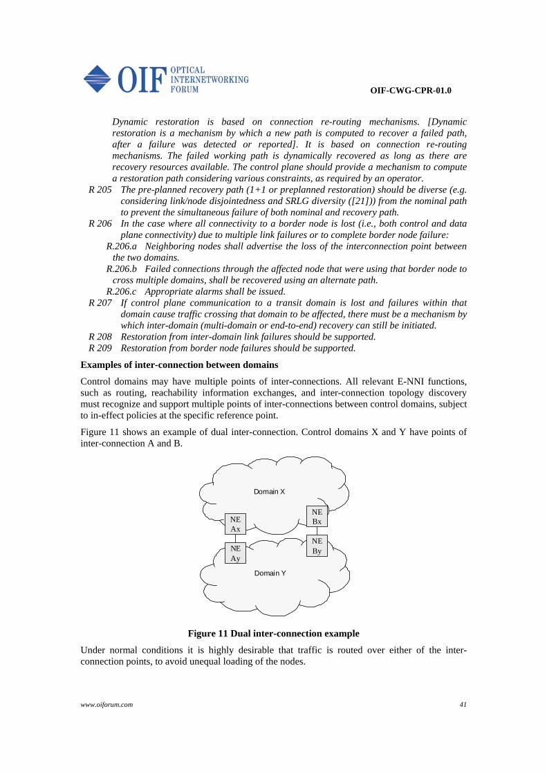
OIF-CWG-CPR-01.0
www.oiforum.com 41
Dynamic restoration is based on connection re-routing mechanisms. [Dynamic restoration is a mechanism by which a new path is computed to recover a failed path, after a failure was detected or reported]. It is based on connection re-routing mechanisms. The failed working path is dynamically recovered as long as there are recovery resources available. The control plane should provide a mechanism to compute a restoration path considering various constraints, as required by an operator.
R 205 The pre-planned recovery path (1+1 or preplanned restoration) should be diverse (e.g. considering link/node disjointedness and SRLG diversity ( [21])) from the nominal path to prevent the simultaneous failure of both nominal and recovery path.
R 206 In the case where all connectivity to a border node is lost (i.e., both control and data plane connectivity) due to multiple link failures or to complete border node failure:
R.206.a Neighboring nodes shall advertise the loss of the interconnection point between the two domains.
R.206.b Failed connections through the affected node that were using that border node to cross multiple domains, shall be recovered using an alternate path.
R.206.c Appropriate alarms shall be issued. R 207 If control plane communication to a transit domain is lost and failures within that
domain cause traffic crossing that domain to be affected, there must be a mechanism by which inter-domain (multi-domain or end-to-end) recovery can still be initiated.
R 208 Restoration from inter-domain link failures should be supported. R 209 Restoration from border node failures should be supported.
Examples of inter-connection between domains
Control domains may have multiple points of inter-connections. All relevant E-NNI functions, such as routing, reachability information exchanges, and inter-connection topology discovery must recognize and support multiple points of inter-connections between control domains, subject to in-effect policies at the specific reference point.
Figure 11 shows an example of dual inter-connection. Control domains X and Y have points of inter-connection A and B.
Domain Y
Domain X
NEAy
NEAx
NEBy
NEBx
Figure 11 Dual inter-connection example
Under normal conditions it is highly desirable that traffic is routed over either of the inter-connection points, to avoid unequal loading of the nodes.
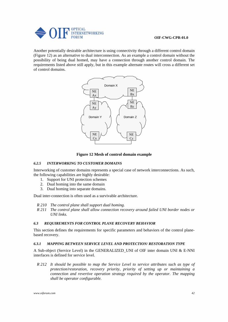
OIF-CWG-CPR-01.0
www.oiforum.com 42
Another potentially desirable architecture is using connectivity through a different control domain (Figure 12) as an alternative to dual interconnection. As an example a control domain without the possibility of being dual homed, may have a connection through another control domain. The requirements listed above still apply, but in this example alternate routes will cross a different set of control domains.
Domain X
Domain ZDomain Y
NECx
NECz
NEAy
NEAx
NEBz
NEBx
Figure 12 Mesh of control domain example
6.2.5 INTERWORKING TO CUSTOMER DOMAINS
Interworking of customer domains represents a special case of network interconnections. As such, the following capabilities are highly desirable:
1. Support for UNI protection schemes 2. Dual homing into the same domain 3. Dual homing into separate domains.
Dual inter-connection is often used as a survivable architecture.
R 210 The control plane shall support dual homing. R 211 The control plane shall allow connection recovery around failed UNI border nodes or
UNI links.
6.3 REQUIREMENTS FOR CONTROL PLANE RECOVERY BEHAVIOR
This section defines the requirements for specific parameters and behaviors of the control plane-based recovery.
6.3.1 MAPPING BETWEEN SERVICE LEVEL AND PROTECTION/ RESTORATION TYPE
A Sub-object (Service Level) in the GENERALIZED_UNI of OIF inter domain UNI & E-NNI interfaces is defined for service level.
R 212 It should be possible to map the Service Level to service attributes such as type of protection/restoration, recovery priority, priority of setting up or maintaining a connection and revertive operation strategy required by the operator. The mapping shall be operator configurable.
OIF-CWG-CPR-01.0
www.oiforum.com 43
An operator can configure the mapping between Service Level and service attributes based on defined Service Level Specifications (SLS) for the client. The mapping function is performed either in a Local Policy Decision Point (LPDP) or a centralized Policy Decision Point (PDP), e.g. using COmmon Policy Service (COPS).
R 213 Policy enforcement and decision points shall be able to provide the mapping between Service Level and operator-specific service attributes (type of protection/restoration, priority, reversion, etc.) at the source node and at domain ingress nodes.
R 214 The above mapping should be configurable via the management plane by network operator.
R 215 As part of policy configuration, an operator shall be able to: R.215.a Specify the revertive operation per domain R.215.b Specify the revertive operation per call R.215.c Specify the revertive operation per connection
6.3.2 CONTROL OF RE-ROUTING BEHAVIOR
During recovery from transport plane failures, the network may be in a transient state where information about failed resources has not yet propagated throughout the network. Failures may also affect multiple connections, resulting in contention for available resources. Control plane traffic may also peak during these situations due to routing messages for topology change and signaling messages for connection recovery. It is important that steps be taken to expedite the recovery process and minimize the adverse effects that can result from this condition.
Crankback behavior
Crankback is a scheme where the node unable to progress the connection setup (due to lack of resources availability, blocked resource, failed link to be used…) returns information to the upstream repair node or source node to allow new connection setup attempts to be made avoiding the blocked resources. The following functional requirements address crankback behavior:
R 216 Inter-domain policy shall determine what crankback information will be collected from a domain, to be used in the event of a failure.
R 217 Control of crankback behavior should be an attribute that is configurable by the management plane.
Failure Reporting
R 218 The control plane shall provide mechanisms that support information exchange with sufficient details on the failures so that it can be used to avoid routing through failed resources.
R 219 The notification mechanism shall be capable of being targeted according to policy (e.g., across domains to source nodes or intra-domain to domain ingress nodes).
R 220 The notification mechanism may be used to expedite the propagation of error notifications, but in a network that offers crankback routing at multiple nodes, there would need to be coordination to avoid multiple nodes attempting to repair the connection at the same time.
Limiting Re-Routing Attempts
Each repair node should apply a locally configurable limit to the number of attempts it makes to re-route a connection. This helps to prevent excessive network usage in the event of significant
OIF-CWG-CPR-01.0
www.oiforum.com 44
faults, and allows back-off to other repair nodes which may have a better chance of routing around the problem.
R 221 It shall be possible to limit the number of re-routing attempts or the time allocated for re-routing attempts according to local policy.
Re-use of resources
As a matter of practicality, it is highly desirable to use network resources efficiently and to minimize long reroutes when possible. Therefore, it is considered important to be able to reuse resources allocated to a connection whenever possible.
R 222 It should be possible to re-use segments of its own nominal path for the restoration of a failed connection.
R 223 It should be possible to re-use segments of its own current path for the restoration of a failed connection.
This feature might be highly desirable especially for the:
Domains which are not impacted by the transmission failure
Ingress and egress nodes in a transit domain which do not change for the new path
6.3.3 REVERSION
In this document Reversion refers to moving a connection back to its nominal path. Reversion may be a control plane or management plane driven operation. In order to support revertive operation, resources allocated to a connection’s nominal path may not be allocated to other connections. It is important to have mechanisms available that allow reversion to be performed with minimal service impact.
R 224 Reversion should be selectable on per call or per connection basis. R 225 The reversion process shall re-route the connection to its Nominal Path. R 226 Even after multiple re-routes, the connection shall revert to its Nominal Path. R 227 For supporting revertive restoration operation the resources from the Nominal Path
shall be reserved during the restoration/re-routing process (note that resources from the Current Path do not have to be reserved).
R 228 Reversion parameters shall be configurable consistent with operator policy (E.g. manual/automatic, WTR time, quality threshold).
R 229 Reversion shall be invoked by the control plane or the management plane. It shall support automatic, manual or forced options.
OIF-CWG-CPR-01.0
www.oiforum.com 45
7 Scalability and Performance In order to allow the switched transport services to expand into a global service, and in order to support different client signals by the switched transport network, the control plane signaling and routing mechanisms must be scalable and should provide fast execution of the requested connection services. At the same time, protection and restoration schemes should be fast enough to ensure that service disruptions are within acceptable levels.
Hierarchical representation of domains is one of the practical methods to achieve routing scalability. The control plane for transport networks is required to support multi-level hierarchy.
7.1 SCALABILITY
7.1.1 NETWORK SCALABILITY
Scalability refers to the ability of the control plane to support ever-increasing requests and support for different clients with an existing switched infrastructure. Performance refers to the ability of the control plane to maintain the same/similar time for completing connection requests.
It is expected that the control plane will support large scale networks with regards to number of nodes, size of nodes, number of control domains, number of established calls/connections and number of simultaneous service requests, including recovery actions (e.g., it is widely accepted that restoration puts most stress on the control plane). While some applications may be small, the control plane must be able to scale to support large networks. An example of order of magnitude is given below:
1 000 nodes in the core network
100 000 nodes in metro and access networks.
1 000 000 connections in the network.
R 230 The control plane must support data plane growth in the future. R 231 The control plane architecture, components, and protocols shall ensure that the
network can scale while maintaining the performance objectives specified, at a minimum relative to:
R.231.a Number of control plane open interfaces (UNI and E-NNI reference points) R.231.b Number of calls and connections R.231.c Number of nodes R.231.d Number of interfaces per node R.231.e Number of links R.231.f Number of control domains R.231.g Number of simultaneous requests per UNI-N instance or controller.
R 232 SCN must be scalable while maintaining its performance objectives.
7.1.2 PARTITIONING AND/OR AGGREGATION OF DOMAINS
As the switched network grows, different network domains may be created, leading to both aggregation and segmentation of existing domains based on business-related activities. This segmentation and aggregation of domains (which may include areas or AS) may be performed manually with many implications for updating routing tables. In order to support a switched
OIF-CWG-CPR-01.0
www.oiforum.com 46
network that automatically reconfigures its domain information to better align with the scalability and performance objectives, a capability to perform the segmentation and aggregation function may be automated.
Transport domain partitioning and/or aggregation must be support in accordance with G.805.
R 233 The control plane should be able to support partitioning and/or aggregation of operating control domains into a set of sub-domains. The partitioning and/or aggregation of control domains shall not affect established connections.
R 234 The control plane should allow network domain partitioning and/or aggregation operations.
7.1.3 INTER-DOMAIN ROUTING PROTOCOL SCALABILITY
R 235 The routing protocol shall be scalable, while maintaining its performance objectives with increasing network size, to support transport network growth at a minimum in the areas of:
R.235.a Link capacity, number of links and granularity R.235.b Number of nodes R.235.c Number of links R.235.d Number of hierarchical levels R.235.e Number of domains.
R 236 The routing protocol shall enable the addition of NEs, links, customers, or domains without requiring an overhaul.
R 237 The routing protocol design shall keep the network size effect as small as possible. R 238 The routing protocol(s) shall be able to minimize global information and keep
information locally significant as much as possible. R 239 Network domain topology summarization and abstraction shall be supported to ensure
network scalability.
7.1.4 SIGNALING PROTOCOL SCALABILITY
R 240 The signaling protocol shall be scalable, while maintaining its performance objectives with increasing network size, to support transport network growth at a minimum in the areas of:
R.240.a Link capacity, number of links and granularity R.240.b Number of nodes R.240.c Number of domains.
R 241 The signaling protocol shall enable the addition of NEs, links, customers, or domains without requiring an overhaul.
R 242 The control plane must accept and process a large number of simultaneous UNI (e.g., for SCs) and/or management plane (e.g., for SPCs) requests per controller.
R 243 The control plane must accept and process requests even if a single signaling message cannot contain all of the necessary information and it needs to be split into multiple messages.

OIF-CWG-CPR-01.0
www.oiforum.com 47
7.2 PERFORMANCE & STABILITY
7.2.1 CONTROL PLANE PERFORMANCE
R 244 The control plane (e.g., SCN, protocol controllers, call, connection and routing controllers) must handle large volumes of simultaneous information exchange requests among call, connection, and routing controllers without service disruption and with minimal performance degradation.
R 245 The control plane (e.g., SCN, protocol controllers, call, connection and routing controllers) shall support increased message streams due to failure/overload conditions (e.g., including both routing updates and restoration signaling).
R 246 Control communications shall ensure that critical messages do not get locked out and control messages do not overwhelm the control plane operations
R 247 The control plane shall ensure that there are no unaccountable network resources. R 248 The control plane shall enable periodic or on demand clean-up of network resources,
as requested and administered by the management plane.
7.2.2 SIGNALLING PROTOCOL STABILITY
R 249 The control plane shall provide mechanisms to ensure that a malfunctioning UNI client does not impact the control plane performance (e.g., untimely request generation, corrupted information).
R 250 The control plane shall provide mechanisms that can limit the rate at which UNI requests from the same client device or on behalf of the same client device are accepted by the network.
7.2.3 ROUTING STABILITY
An excessive rate of advertised topology, resource and reachability updates and long routing convergence times may cause network performance degradation. This is particularly relevant when hop-by-hop routing is employed.
R 251 The control plane shall provide mechanisms to speed-up convergence and to reduce the number of route flaps after link-state updates (in order to minimize the duration of unstable operational conditions).
R 252 The control plane should use appropriate refresh time scales to minimize the amount of information flow.
R 253 Major state changes should be advertised as they occur.
After transitory control plane failures, it might be desirable to pick-up a pre-established adjacency rather than creating a new one, forcing former adjacencies to be removed from the link-state database.
R 254 The control plane shall have current network state knowledge. Resynchronization of the network state shall be supported after any failures of the control plane.
In order to ensure reliable and loop-free flooding the following requirements need to be observed.
R 255 The control plane shall support flooding optimizations on a per-neighbor basis in order to avoid overheads when multiple links exist between neighboring nodes.
R 256 The control plane shall support mechanisms to ensure loop-free flooding.
OIF-CWG-CPR-01.0
www.oiforum.com 48
R 257 Routing protocols shall be reliable and resilient to many types of failure. Inter-domain link-state update messages should reach every single node within the flooding scope limits.
R 258 Expired link-state information shall be removed from every node independently.
Finally, another aspect limiting quick convergence is the database overflow.
R 259 Link state database overflow should be avoided.
7.2.4 CONTENTION RESOLUTION
Contention is a problem that arises when two independent requests for the same resource arrive at the same time. Unresolved contention in the control plane may cause call blocking (see G.7713 for details).
In this section we focus on general requirements for contention resolution in transport networks.
R 260 Contention avoidance support is preferable over contention resolution. However, when contention occurs in establishing connections over E-NNI, there shall be at least one attempt and at most N attempts at contention resolution before returning a negative acknowledgment where N is a configurable parameter with default value of 3.
R 261 Signaling shall not progress through the network with unresolved contention for any network resources.
R 262 The control plane shall not allow cross-connections with unresolved contention for any network resources.
R 263 Acknowledgements of any requests shall not be sent until all necessary steps to ensure request fulfillment have been successful.
R 264 Contention resolution attempts shall not result in infinite loops. R 265 Contention resolution mechanisms should minimize control signaling and latency
overheads.
7.2.5 RECOVERY PERFORMANCE
R 266 When control plane handles 1+1 protection, the sub 50ms protection time shall be supported6
R 267 When control plane handles 1:N protection, the sub 50ms protection time should be supported6
R 268 Restoration mechanisms should be able to recover connectivity from a data plane failure within less than ten seconds. Thus, the connection is not considered unavailable as defined in G.826, G.828 and G.8201.
6 Note that complementary mechanisms like OAM, failure detection at data plane... might be needed to achieve such target.
OIF-CWG-CPR-01.0
www.oiforum.com 49
8 Security and Logging
8.1 PROTOCOL SECURITY
Security mechanisms are required to protect the signaling, routing, and discovery protocols used in the optical control plane, because these protocols govern the use of significant network resources. Carriers may need to protect topology, reachability, addressing, and usage details about their own networks as well as information about their customers.
Security mechanisms guard against attacks that may compromise control plane availability, seek unauthorized use of resources, or attempt to gain unauthorized information about configuration and usage. Just as any other functionality, security consumes resources, and it must be designed from a point of view that keeps its costs and benefits properly aligned. Communication protocols usually require two main security mechanisms: integrity and confidentiality. Integrity mechanisms ensure data origin authentication and message integrity of UNI or E-NNI messages so that unauthorized operations can be detected and discarded. For example, the UNI message integrity service can prevent a malicious UNI-C agent from causing denial of service at a service provider by sending an excessive number of forged connection creation requests. Integrity mechanisms detect and reject attempts to forge messages and to reorder, duplicate, truncate, or otherwise tamper with the proper sequence of messages. These mechanisms can also provide replay protection and non-repudiation. Replay protection is used to detect any reinsertion of previously sent messages into the communications channel, which can be used to gain unauthorized access. Replay protection is normally achieved by adding sequence numbers to the messages or by relying on another protocol (e.g., TCP) to guarantee the proper sequencing of the message stream above the integrity service. Non-repudiation provides evidence that prohibits a sender from denying sending a message, thus holding the sender accountable. This may be desirable for accounting and billing purposes. Message integrity and confidentiality are normally achieved using symmetric cryptographic algorithms. These algorithms require pairwise shared secret keys and do not provide non-repudiation. To facilitate the use integrity and confidentiality services, public-key or asymmetric cryptographic algorithms are typically used, initially, to provide two-way peer entity authentication and key agreement. Asymmetric algorithms can also provide digital signatures, which can be used to implement a non-repudiation service. The use of asymmetric algorithms may be supported by a public-key infrastructure (PKI) or some other, community-defined, key assignment scheme. Asymmetric algorithms are typically more computationally intensive than symmetric algorithms. It is expected that from the point of view of the UNI 2.0 and E-NNI requirements, the most important security feature could be message integrity. Confidentiality of messages is also likely to be desirable, especially in cases where message attributes include information private to the communicating parties (either the customer or network operator). Examples of such attributes include details about the users, such as account numbers, contract identification numbers, etc. The distributed nature of the control plane increases the need for security. The network elements comprising the control plane are connected via devices such as layer 2 switches and IP routers. Because these network elements can belong to different network operators and may be outside the control of a single carrier, control communication between them is subject to increased security threats, such as IP address spoofing, eavesdropping, denial of service attacks, and unauthorized

OIF-CWG-CPR-01.0
www.oiforum.com 50
intrusion attempts. To counter these threats, appropriate security services need to be deployed to protect the control channel protocols. Security protocols cannot guarantee availability, but they can support robustness and availability by identifying and rejecting inappropriate traffic aimed at consuming excessive resources or corrupting the network configuration. To this extent, it is important that the security protocols themselves cannot be used as part of such an attack.
Therefore, security should be:
Optional to implement and to use. Some users may decide that they can implement adequate protection by other means (e.g., perimeter access controls and firewalls), so that protocol security is unnecessary. Vendors who choose to serve these users may offer a product without these security services.
Interoperable. The purpose of having a standard set of security services in UNI and E-NNI is to ensure that protocol security interoperates between vendors’ products within and between carriers’ networks. Thus, the security services defined should have as few methods, formats, optional features, and algorithms as possible. The same methods should work with different Layer 2 protocols and with IPv4 or IPv6.
Synergistic with other functionality. Security for control protocols (including signaling, routing, and discovery) is less costly and less error prone to implement and deploy if the same solution is used for all control plane protocols, interfaces to management systems, and other user services like VPNs.
High assurance. Solutions should be preferred if they are already well standardized, extensively analyzed, and widely used.
Readily available in reference implementations. This encourages the development of correct, complete, and interoperable implementations.
High quality. The algorithms and protocols should be chosen based on the level of security required. They should have no known defects or serious weaknesses, and the security should be designed to work correctly within a broad model of both active and passive attacks.
Efficient. Standard state-of-the-art microprocessors should be able to perform many instances of the authentication and key negotiation protocol and tens of megabits of traffic protection per second of processing time. Dedicated hardware modules should be able to increase these numbers by two orders of magnitude.
In summary, to satisfy the above requirements, security for UNI and E-NNI control protocols must support confidentiality, data origin authentication, data integrity, and replay detection on a per-message basis. Two-way authentication of the parties must be integrated with an automated key management system.
R 269 All Control Plane protocols shall include optional and interoperable security mechanisms (a) to authenticate entities exchanging information across an interface; (b) to guarantee the integrity of the information exchanged across an interface and to detect replay attacks; (c) to protect the confidentiality of information that communicating entities may be required to keep secret from other parties.
OIF-CWG-CPR-01.0
www.oiforum.com 51
R 270 These security mechanisms shall protect against passive eavesdropping and active attacks against the optical network as well as unintentionally malfunctioning control entities (for example, due to software or configuration errors).
R 271 These security mechanisms shall be designed to prevent or limit the effect of denial of service attacks.
R 272 These security mechanisms shall be designed so they can be extended to incorporate or accommodate the particular or proprietary needs of individual users and be kept up to date with advances in security technology.
R 273 Tools and methods shall be included with these security mechanisms to specify and configure them based on policy, operate them with minimal manual intervention, and audit their correct operation.
R 274 To reduce implementation cost, improve manageability, enhance interoperability, reduce the risk of errors, and provide compatibility with other protocols, these security mechanisms should be based on a minimal, well-understood, and widely used set of cryptographic primitives at the network or transport layer and a comprehensive key management system that can be used with all Control Plane protocols (e.g., signaling, routing, and discovery).
R 275 The security system shall provide a mechanism to specify and enforce a security policy that states where and when security services must be applied.
8.2 SECURITY FOR ALARMS, NOTIFICATIONS, AND LOG MESSAGES
One of the main purposes of logging and auditing is to determine, with some degree of certainty, what events have occurred in the case of an intrusion, malfunction, or unauthorized modification of a system. Log messages can also help diagnose and verify the end-to-end operation of control plane protocols. Thus, log records need to be secured against forgery, tampering, or destruction.
Users need to provide sufficient resources for the transmission and storage of log records. Therefore, logging should be optional and configurable.
Log records often contain sensitive information about the network configuration, usage patterns, or customers. In such cases, operating system and network protections, such as access controls and firewalls, should be used to restrict access to log data, but encryption is the only effective way to protect this information from eavesdropping during transmission.
R 276 Administrators shall have the ability to configure the generation, disposition, and security of log messages.
R 277 The control plane and management plane shall provide the capability, optionally, to authenticate the origin of alarms, notifications, and log messages.
R 278 The control plane and management plane shall provide the capability, optionally, to protect alarms, notifications, and log messages from forgery, tampering, or replay.
R 279 The control plane and management plane shall provide the capability, optionally, to protect the confidentiality of alarms, notifications, and log messages.
R 280 The logging mechanism shall conform to open standards and shall use standard protocols for authentication, integrity, and confidentiality.
R 281 Message source, severity level, and a time stamp shall be included in log messages. R 282 The management plane shall provide a tamper-resistant method that may optionally be
used for storing control plane alarms, notifications, and log messages, suitable for reconstructing an audit trail.
OIF-CWG-CPR-01.0
www.oiforum.com 52
9 Policy Support It is considered that inter-domain interfaces will be driven by individual carriers’ policies, and protocols, behaviors, and capabilities will be adjusted accordingly. Information exchanges between network domains across E-NNI and across UNI will be driven by local policy, subject to business/regulatory agreements in effect at the specific reference point.
R 283 Policies shall be configurable per interface, per customer, and per service type and/or service level and/or on time base.
R 284 The control plane shall allow creation, modification or removal of policies (governing control plane behavior) by the management plane.
Requirements throughout the document point to dependency on individual carriers’ policies. The following summarize these requirements. It should be noted though, that individual carriers may require additional policies to be supported:
Control plane view names for transport resources are not shared, outside of a carrier network boundaries, except for transport resource access points (e.g., inter-connecting resources) that are governed by in-effect policies.
o Clients visibility to carrier transport resource names o Other transport carriers visibility to carrier transport resource names
Transport network addresses are not shared outside of a carrier network boundaries except for transport resource access points (e.g., inter-connecting resources) that are governed by in-effect policies.
o Clients visibility to carrier transport resource addresses o Other transport carriers visibility to carrier transport resource addresses
Transport resource access points (e.g., inter-connecting resources) names and addresses shared with outside network entities (e.g., Client networks or network providers) are governed by in-effect policies.
Reachability information exchanges across inter-domain interfaces (UNI, E-NNI).
Support for discovery mechanisms across E-NNI and UNI to ease operation of multiple domain networks and related calls and connections.
Control plane addresses (SCN addresses) are not shared outside of carrier network boundaries, except for transport resource access points (e.g., inter-connecting resources) that are governed by in-effect policies.
The Control Plane support for requests for call set-up is subject to intra-domain and inter-domain policies in effect.
Call Admission Control shall determine if the call may proceed between source and destination, across multiple domains, within the established policies, before the call is established.
Connection Admission Control shall determine if there are sufficient resources in the network/domain to be allocated to the requested connection, within the established policies.
Individual service level routing constraints shall be governed by carrier policies.
OIF-CWG-CPR-01.0
www.oiforum.com 53
If all the connections associated with a call have been released, the control plane shall allow that the call be released or that the call be maintained without supporting connections, in accordance with in-effect policy.
Call Modification procedures shall be supported according to in-effect policies.
Modification of any connection attribute shall be supported as a network configurable action, subject to established in-effect policies.
All routing information exchange is subject to in-effect policy, including, but not limited to : o Inter-domain topology o Per-domain topology abstraction o Per domain reachability information o Path computation information
The control plane may not require that network related information be shared with other networks unless allowed by local in-effect policy.
Security mechanisms shall be implemented in accordance to individual network provider policies.
Tools and methods shall be included within security mechanisms to allow network providers to specify and configure them based on individual policy.

OIF-CWG-CPR-01.0
www.oiforum.com 54
10 Control Plane / Management Plane Interaction Control plane capabilities must support and enhance management plane capabilities: flow-through provisioning and support processes, ability to support multiple grades of service; rapid recovery, ability to provide the necessary information to the management plane for root cause analysis across domain boundaries, and for determination of capacity growth requirements. This section is not intended to be a detailed requirements document, however it is intended to provide guidance on OAMP-related control plane functionality. The focus of this section is to give guidelines for the relationship between the control plane, the data plane and the management plane and to describe the information flow and control functions that are related to the control plane.
The requirements in this section are OAM&P centered, but they reflect on control plane functionality. This section also addresses the need for the control plane to advertise its health and the health of its sub-components to the management plane.
All of the requirements in this section apply to the information exchange between the control plane and management plane management plane in support of control plane operation.
10.1 INTERACTION BETWEEN CONTROL PLANE AND MANAGEMENT PLANE
Interaction between control plane and management plane is intended to be consistent with the requirements of ITU-T recommendation G.7710 and G.7718. G.7718/Y.1709 discusses the framework for managing ASON networks. It addresses the management aspects of the ASON control plane and the interactions between the management plane and the ASON control plane. This Recommendation follows the TMN principles specified in Recommendation M.3010 and the ASON architecture principles specified in Recommendation G.8080.
R 285 The control plane shall interact with the management plane as defined in G.7710 and G.7718.
10.2 CONFIGURATION AND QUERIES
R 286 Control plane failures shall not affect the normal operation of a configured and operational management plane.
R 287 Management plane failures shall not affect the normal operation of a configured and operational control plane.
R 288 The management plane communications infrastructure shall not be severely impacted by the control plane communications.
R 289 The control plane shall allow the management plane to enable/disable control plane components.
R 290 The control plane shall allow the management plane to enable/disable control plane channels.
R 291 The control plane shall allow the management plane to assign, retrieve, de-assign, configure identifiers for all identifier spaces in the control plane and control plane view of the transport network resources, (e.g., RA identifiers, SNPP identifiers, UNI/E-NNI transport resource identifiers).
R 292 The control plane shall allow the management plane to assign, retrieve, de-assign, or configure the binding for the TNA (UNI transport resource) identifiers per individual carrier's specifications.
OIF-CWG-CPR-01.0
www.oiforum.com 55
R 293 The control plane interfaces shall be configurable as UNI, E-NNI or I-NNI by the management plane, and their behavior shall be consistent with the configuration (i.e., external versus internal interfaces).
R 294 The control plane shall allow creation, modification or removal of policies (governing control plane behavior) by the management plane.
R 295 The control plane shall allow the management plane to allocate or de-allocate resources to and from the control plane.
R.295.a If resources are supporting an established connection and the resources are requested to be de-allocated from the control plane, the control plane shall first re-route the connection in such a way that is does not use any of these resources, before the resources are de-allocated.
R 296 The management plane shall be able to prohibit the control plane from using certain transport resources not currently being used.
R 297 The control plane shall allow the management plane to take or to relinquish control over existing calls. All the connections associated with the transferred call shall be transferred under the control of the management plane.
R 298 The control plane shall accept transfer of control for established connections from the management plane, while ensuring that this process shall not cause a disruption of the established connections.
R 299 The control plane shall allow the management plane to take control over existing connections while ensuring that this process shall not cause a disruption of the established connection.
R 300 The management plane shall be able to query on demand the status of a connection irrespective of how it was set up.
R 301 The control plane shall not assume authority over management plane provisioning functions.
R 302 The control plane shall allow the management plane to set and modify the connection characteristics.
R 303 The control plane shall not assume authority over management plane performance management functions.
R 304 The management plane shall be able to query the operational state of all control plane components.
R 305 The control plane shall support queries from the management plane on topology and utilization information for its subtending domain.
R 306 The control plane shall support queries from the management plane on any topological information.
R 307 The control plane shall enable periodic or on demand clean-up of network resources, as requested and administered by the management plane, to avoid build-up of partial connections in the network.
R.307.a For specific resources. R.307.b For a domain.
R 308 The control plane shall allow the management plane to tear down connections established by the control plane both gracefully and forcibly on demand.
R 309 The control plane shall allow management plane queries on explicit route information for a connection or a group of connections, based on connection IDs.
R 310 The control plane shall support queries from the management plane on any call and connection information including route information and call or connection attributes as per carrier's policy.

OIF-CWG-CPR-01.0
www.oiforum.com 56
10.3 NOTIFICATIONS AND ALARMS
R 311 The control plane shall autonomously notify the management plane of the connection request Success/Failure.
R.311.a Upon a connection request failure, the control plane shall autonomously report to the management plane. At a minimum the report shall include the source, destination and a cause code identifying the reason for the failure.
R 312 When contention on a resource exceeds a threshold, it shall be reported autonomously to the management plane. The threshold value shall be reconfigurable.
R 313 The control plane shall provide notifications of current period and historical counts for call attempt, call set-up failures, successes, and contention occurrences.
R 314 The management plane shall be able to query the connection attempt, connection set-up failures, successes, and contention occurrences.
R 315 The control plane shall support monitoring in the following areas: R.315.a Congestion on the SCN. R.315.b Control plane components overloading. R.315.c Excessive delay in the control plane component communications. R.315.d Abnormal/excessive routing table updates. R.315.e Control plane component restarts. R.315.f Excessive delay in control plane interaction with transport resources.
R 316 The Control Plane shall support Autonomous Alarm Reporting for each of the control plane components.
R 317 Detailed alarm information shall be included in the alarm notification for each of the control plane components including: resource in alarm, the time the alarm occurred, the probable cause, and the perceived severity of the alarm.
R 318 The Control Plane shall support the ability to retrieve all or a subset of the Currently Active Alarms for each of the control plane components.
R 319 The Control Plane shall not lose alarms for any of the control plane components. Alarms lost due to transmission errors between the Control Plane and the management plane shall be able to be recovered through management plane queries to the alarm notification log.
R 320 The Control Plane should supply the management plane with the ability to administer the alarm severity of the resources in alignment with TMN requirements modeled in ITU Rec. M.3100 and M.3120.
R 321 The Control Plane shall support alarm correlation for control plane components and report the root cause alarm, lower order alarms shall be logged.
10.4 USAGE INFORMATION
R 322 The control plane shall have the capability to provide usage information to the management plane.
R 323 The control plane shall record aggregated usage information for network resources. R 324 If usage exceeds a threshold, the control plane shall notify the management plane. The
usage threshold shall be configurable. R 325 The control plane shall record network usage per individual client device and per
connection. R 326 Usage information shall be able to be queried by the management plane.
OIF-CWG-CPR-01.0
www.oiforum.com 57
11 References ITU-T Recommendations:
[1] G.707 (10/2000): Network node interface for the synchronous digital hierarchy (SDH)
[2] G.709 (03/2003): Interfaces for the Optical Transport Network (OTN)
[3] G.805 (03/2000): Generic functional architecture of transport networks
[4] G.7710 (11/2001): Common equipment management function requirements
[5] G.7712 (03/2003): Architecture and specification of data communication network
[6] G.7713 (12/2001): Distributed call and connection management (DCM)
[7] G.7713 Amendment 1 (06/2004)
[8] G.7714 (11/2001): Generalized automatic discovery techniques
[9] G.7715 (06/2002): Architecture and requirements for routing in the automatically switched optical networks
[10] G.7716: Control plane initial establishment, reconfiguration and recovery
[11] G.7718 (02/2005): Framework for ASON management
[12] G.8010 (02/2004): Architecture of Ethernet layer networks
[13] G.8011 (08/2004): Ethernet over Transport – Ethernet services framework
[14] G.8012 (08/2004): Ethernet UNI and Ethernet NNI
[15] G.8080 (06/2006): Architecture for the automatically switched optical network (ASON), 06/2006 and subsequent Amendment
[16] G.8081 (03/2008): Terms and definitions for Automatically Switched Optical Networks (ASON)
IETF RFC:
[17] RFC2119: Key words for use in RFCs to Indicate Requirement Levels
[18] RFC4428: Analysis of GMPLS-based recovery mechanisms
[19] RFC4872: RSVP-TE Extensions in Support of End-to-End Generalized Multi-Protocol Label Switching (GMPLS) Recovery.
[20] RFC4873: GMPLS Segment Recovery.
[21] RFC5298: Analysis of Inter-Domain Label Switched Path (LSP) Recovery
[22] RFC4657: Path Computation Element (PCE) Communication Protocol Generic Requirements
[23] RFC5376: Inter-AS Requirements for the Path Computation Element Communication Protocol (PCECP)
OIF-CWG-CPR-01.0
www.oiforum.com 58
IETF Drafts
[24] draft-ietf-pce-inter-layer-req-10.txt: PCC-PCE Communication and PCE Discovery Requirements for Inter-Layer Traffic Engineering
MEF documents:
[25] MEF 6.1: Metro Ethernet Services Definitions Phase 2 (July 2008)
[26] MEF 10.2: MEF 10.2 Ethernet Services Attributes Phase 2 (Oct 2009)
[27] MEF 11: User Network Interface (UNI) Requirements and Framework OIF documents:
[28] IA: OIF-UNI-02.0-Common, February 25, 2008
[29] IA: Security Extension for UNI and NNI, OIF-SEP-01.0, May 8, 2003
[30] IA: Addendum to the Security Extension for UNI and NNI, OIF-SEP-02.1, March 31, 2006
[31] IA: Security for Management Interfaces to Network Elements, OIF-SMI-01.0, September 4, 2003
[32] IA: Addendum to the Security for Management Interfaces to Network Elements, OIF-SMI-02.1, March 31, 2006
[33] IA: OIF Control Plane Logging and Auditing with Syslog, OIF-SLG-01.0, November 7, 2007