Embed Size (px)
Citation preview

Judgment of Natural Perspective Projectionsin Head-Mounted Display Environments
Frank Steinicke∗, Gerd Bruder†, Klaus Hinrichs‡
Visualization and Computer Graphics Research GroupDepartment of Computer Science
University of Munster
Markus Lappe2§
Psychology Department IIUniversity of Munster
Scott Kuhl¶
Perception and Computer Graphics Research GroupDepartment of Computer Sciences
University of Utah
Pete Willemsen‖
Department of Computer ScienceUniversity of Minnesota Duluth
Abstract
The display units integrated in todays head-mounted displays(HMDs) provide only a limited field of view (FOV) to the virtualworld. In order to present an undistorted view to the virtual environ-ment (VE), the perspective projection used to render the VE has tobe adjusted to the limitations caused by the HMD characteristics.In particular, the geometric field of view (GFOV), which definesthe virtual aperture angle used for rendering of the 3D scene, isset up according to the display’s field of view. A discrepancy be-tween these two fields of view distorts the geometry of the VE insuch a way that objects and distances appear to be “warped”. Al-though discrepancies between the geometric and the HMD’s fieldof view affect a person’s perception of space, the resulting mini-and magnification of the displayed scene can be useful in some ap-plications and may improve specific aspects of immersive virtualenvironments, for example, distance judgment, presence, and vi-sual search task performance.
In this paper we analyze if a user is consciously aware of perspec-tive distortions of the VE displayed in the HMD. We introduce apsychophysical calibration method to determine the HMD’s actualfield of view, which may vary from the nominal values specifiedby the manufacturer. Furthermore, we conducted an experiment toidentify perspective projections for HMDs, which are perceived asnatural by subjects-even if these perspectives deviate from the per-spectives that are inherently defined by the display’s field of view.We found that subjects evaluate a field of view as natural when it islarger than the actual field of view of the HMD; in some case up to50%.
CR Categories: H.5.1 [Information Interfaces and Presentation]:Multimedia Information Systems—Artificial, augmented, and vir-tual realities; I.3.7 [Computer Graphics]: Three-DimensionalGraphics and Realism—Virtual reality
Keywords: Virtual reality, head-mounted displays, field of view
1 Introduction
Immersive virtual environments (VEs) are often characterized byhead-mounted displays (HMD) and a tracking system for measur-ing a user’s position and orientation. Such head- or helmet-mounteddisplays are head-worn devices, which consist of either one or two
∗e-mail: [email protected]†e-mail: g [email protected]‡e-mail: [email protected]§e-mail: [email protected]¶e-mail: [email protected]‖e-mail: [email protected]
small displays with lenses and semi-transparent mirrors that are em-bedded in eye-glasses, a helmet, or a visor. These miniaturized dis-play units consist of CRTs, LCDs, Liquid Crystal on Silicon, orOLEDs [Burdea and Coiffet 2003]. Some vendors employ multipleof such micro-displays to increase the total resolution and field ofview. Applications can differ in whether HMDs display computer-generated images, images from the real world captured by camerasattached to the HMD, or a combination of both as used in aug-mented reality or mixed reality environments. Sophisticated HMDsare equipped with a tracking system that determines the wearer’shead position/orientation, so that a tracked motion of the HMDleads to a corresponding change of the virtual view. This allows to“look around” in a virtual reality (VR) environment similar to thereal world, i. e., turning the head leads to a rotation of the virtualcamera without the need for additional input devices. In the scopeof this paper we focus on immersive VEs, and consider HMDs thatdisplay computer-generated images with respect to a user’s headmotions.
The most often named requirements for a HMD are a high resolu-tion and a large field of view (FOV). This FOV refers to the hor-izontal and vertical angles subtended by the display. In compar-ison to the effective visual field of humans, which approximates200 degrees horizontally and 150 degrees vertically [Warren andWertheim 1990], many commercially available HMDs have rela-tively narrow fields of view, ranging roughly from 20 to 80 degreesdiagonally. In order for a virtual world to be displayed on a HMD,the computer graphics system must determine which part of the VEis to be viewed by the user. In contrast to the display’s FOV, thegeometric field of view (GFOV) defines the horizontal and verticalboundaries of the virtual viewing volume along with the aspect ra-tio. With such a setup user movements tracked in the laboratory aremapped to position, orientation and/or projection changes of a vir-tual camera. Usually, tracked head pose changes are applied to thevirtual camera by means of a one-to-one mapping, and define thecamera’s position and orientation in the VE; the projection of thevirtual camera defines the view frustum. In most VR applications aperspective projection is chosen such that depth cues are consistentwith a user’s real-world view. Near and far clipping planes definethe bounds of the visible scene. The horizontal and vertical geomet-ric fields of view define the angles subtended by the viewport fromthe center of projection in virtual space or, equivalently, the anglesubtended by the camera’s view frustum. The image projected ontothe viewport is displayed on the physical screen of the HMD.
If the GFOV matches the field of view of the HMD, the viewportis mapped from virtual space onto the physical display in such away that users perceive a “correct” perspective (assuming that weneglect other distortions of the display device such as pincushiondistortion). On the other hand, if the GFOV varies from the dis-play’s FOV, it results either in mini- or magnification of the graph-

ics [Kuhl et al. 2008] (cf. Appendix). As illustrated in Figure 1(a),if the GFOV is smaller than the FOV of the HMD, the viewport im-age will appear magnified on the physical display because of the re-quirement for the image to fill a larger subtended angle in real spaceversus virtual space. Conversely, if the GFOV is larger than theFOV of the HMD, a larger portion of the VE needs to be displayedin the image, which will appear minified (see Figure 1(c)). De-pending on the distortion of the geometry of the VE the visual op-tical flow rate decreases or increases proportionately [Draper et al.2001]. The optical flow rate is an essential visual motion patternthat in principle allows humans to extract self-motion information.Hence, manipulation of the GFOV provides a controllable opticaldistortion resulting in different visual-vestibular patterns in immer-sive VEs.
In this paper we analyze how much perspective distortion caused bya deviation between the GFOV and display’s FOV is unnoticeableto HMD users. In particular, we determine how the geometric fieldof view needs to be specified in a HMD environment such that usershave the impression that virtual and real perspectives match. Thepaper is structured as follows. Section 2 summarizes work relatedto our approach. Section 3 introduces a psychophysical calibra-tion method to identify the display’s actual FOV. In the experimentdescribed in Section 4 we used a virtual one-to-one copy of ourreal laboratory surroundings, and subjects had to adjust the per-spective projection until they felt confident that the perspective ofthe displayed scene matched the perspective in the real laboratory.Section 5 discusses the results of the experiments as well as impli-cations about how to set up the virtual perspective in HMD environ-ments. Section 6 concludes the paper and gives an overview aboutfuture work.
2 Related Work
Since most commercially available HMDs have relatively narrowfields of view in comparison to the effective visual field of humans,HMD users can see only a portion of the virtual world if the GFOVmatches the display’s FOV. In the real world, a narrow field of vi-sion has been shown to degrade human performance in navigationand manipulation tasks [Jansen et al. 2008; Hassan et al. 2007],spatial awareness, and visual search tasks [Arthur 1996]. There hasbeen much evidence that a restricted FOV in the virtual world maylead to perceptual, visual, and motor decrements in various kinds ofperformance tasks [Alfano and Michel 1996; Hagen et al. 1978].
As mentioned in Section 1, if the GFOV matches the display’s FOV,the viewport is mapped directly from virtual space onto the phys-ical display, and therefore users perceive a “correct” perspective.However, a deviation between the GFOV and the FOV of the HMDoccurs, for example, when the display’s actual field of view variesfrom the nominal values specified by the HMD manufacturers. Adeviation can also be induced intentionally. Sometimes VR appli-cation developers use a larger GFOV in order to provide a widerview to the virtual world. Such deviations result in mini- or magni-fication of the graphics (cf. Appendix). Choosing the largest fieldof view possible may not always be optimal, since the required sizeof the GFOV for a HMD mainly depends on the application underconsideration. If the GFOV is larger than the display’s FOV, the dis-play resolution decreases because the same pixels are mapped to alarger display area. Furthermore, a large FOV may be unnecessaryfor tasks, which are localized within a small spatial region of in-terest [Hassan et al. 2007], and it may aggravate simulator sicknesseffects, particularly those caused by vection and visual-vestibularmismatch [Stanney and Kennedy 1997; Seay et al. 2002].
However, an increased GFOV affords the inclusion of more infor-mation in the 3D view, and for a broad class of applications a larger
field of view is essential, since it has the potential to improve im-mersion and to increase the user’s sense of presence [Seay et al.2002; Allison et al. 1999]. Several works have introduced thesedeviations in order to address limitations of small display spacesin two-dimensional desktop environments, for example using Fish-Eye views [Furnas 1986].
Even if GFOV and display’s FOV match, viewing the real worldvaries significantly from viewing a virtual world through a HMD.Many studies that compared distance perception of static targets inimmersive VEs and in the real world found evidence that distancesare perceived as compressed in VEs relative to the real world [Wit-mer and Kline 1998; Willemsen and Gooch 2002; Messing andDurgin 2005; Gooch and Willemsen 2002]. It has been shownthat as long as HMD users look around in a real or virtual envi-ronment, a restricted field of view (like a 60 degree diagonal FOV)did not change their behavior on blind walking distance estimationtasks [Creem-Regehr et al. 2005; Knapp and Loomis 2004; Loomisand Knapp 2003]. However, previous studies have suggested thatphysical factors related to the ergonomics of head-mounted dis-plays may account for some of the apparent compression [Willem-sen et al. 2009; Kuhl et al. 2006; Kuhl et al. 2008; Thompson et al.2004; Knapp and Loomis 2004].
However, an explanation for the larger portion of the observed com-pression effects remains unknown. Given that underestimation hasbeen found in a number of studies using HMDs and that HMD dis-plays typically have a reduced FOV, the restricted field of view hasbeen suspected as a factor influencing distance perception [Witmerand Kline 1998; Psotka et al. 1998].
Although researchers have investigated the effects of the GFOVon performance and level of presence experienced [Hendrix andBarfield 2000], few studies have explicitly considered the relation-ship between GFOV and the display’s FOV. In the experiments de-scribed by Kuhl et al. [Kuhl et al. 2008] subjects saw the virtualworld with a FOV that was larger (20%) than the one provided bythe HMD resulting in minification of the graphics. In this case, thetypical spatial compression effects in direct blind walking tasks inVEs was reduced, i. e., subjects walked significantly farther to pre-viously seen targets when the graphics were minified. The workprimarily focused on measuring the effects of mini- and magnifi-cation on distance judgments instead of measuring if subjects wereconsciously aware of the distortion. Since subjects had to walkwithout vision, they did not perceive any visual flow information.As explained above, mini- or magnification strongly affects the vi-sual optical flow rate, which is an essential visual motion patternthat allows humans to extract self-motion information. Therefore,we are interested in analyzing how much deviation between GFOVand the display’s FOV is unnoticeable for users and which GFOVis perceived as most natural.
3 Psychophysical Calibration of GFOV
As mentioned in Section 2, a HMD’s actual FOV may vary from thenominal values specified by the manufacturer. In this section we de-scribe a psychophysical calibration method for HMDs that allowsto determine a display’s actual FOV. Usually, the nominal FOV forHMDs is specified as visual angle across the diagonal of the screen.Since most graphics systems require the horizontal and vertical (in-stead of the diagonal) fields of view of the display, almost all HMDusers convert the nominal diagonal FOV into geometric horizon-tal and vertical fields of view, often assuming a square-pixel aspectratio. However, according to Kuhl et al. [Kuhl et al. 2008], the hor-izontal and vertical geometric fields of view determined in such away can fail to match the FOV of the HMD for three reasons:

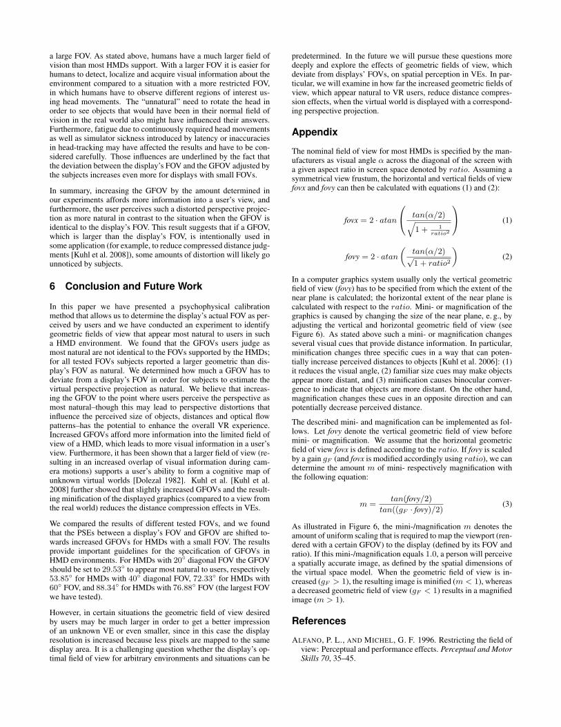
(a) gF = 0.8 (b) gF = 1.0 (c) gF = 1.2
Figure 1: llustration of different perspective projections in a virtual 3D model of our laboratory: (a) with a GFOV, which is larger than,(b) identical to and (c) smaller than the display’s actual FOV. The top row shows the virtual laboratory and the camera frustums from atop-down view, the bottom row shows the corresponding renderings of the laboratory with GFOVs which have been manipulated with gainsof (a) gF = 0.8, (b) gF = 1.0 and (c) gF = 1.2.
1. The nominal diagonal FOV may differ from the display’s ac-tual diagonal FOV.
2. The actual aspect ratio of the display may not match the ratioof horizontal to vertical pixel counts.
3. Pincushion distortion may lead to different FOV values.
In order to account for the three sources of error, different calibra-tion methods have been proposed to identify the actual FOV of aHMD [McGarrity and Tuceryan 1999]. Ellis and Nemire [Ellis andNemire 1993; Nemire and Ellis 1993] displayed vertical poles inthe HMD. When wearing the HMD, subjects had to point at theperceived location of the poles in the real world. This allows tocalculate how the GFOV has to be specified so that the virtual an-gles and pointed angles match. Another method [Rinalducci et al.1996] uses a camera flash to provide subjects with an afterimageof a known visual angle. When wearing the HMD, subjects usedthis afterimage to measure the FOV of the display. It may also bepossible to calibrate non-see-through HMDs by adapting methodsused for see-through display calibration [Gilson et al. 2008]. An-other simple calibration approach requires VR users to adjust theGFOV by comparing a real object with a virtual object by con-stantly raising and lowering of the HMD [Kuhl et al. 2008]. In thefollowing we describe a psychophysical calibration method to iden-tify the actual FOV of a HMD in a more precise way in comparisonto previously described methods.
Psychophysics is an area of perceptual psychology that employsspecific behavioral methods to study the relation between stimulusintensity and perception reported by a human observer. The amountof change in a stimulus required to produce a noticeable sensationis defined as the just noticeable difference (JND). In the calibrationprocess discussed here, subjects had to report their judgments ofdifferent GFOVs based on a two-alternative forced-choice task (2-AFCT). In order to manipulate the GFOV we apply field of viewgains gF [x] ∈ R+ and gF [y] ∈ R+ to the virtual camera frustum byreplacing the horizontal angle fovx and the vertical angle fovy of thegeometric field of view with gF [x] ·fovx and gF [y] ·fovy respectively.
Figure 2: Picture taken during the psychophysical calibration pro-cess. A participant at a fixed position compares the size of the hor-izontal stripe in the real world with the virtual stripe displayed onthe HMD (see inset).
In the psychophysical calibration process described in this section,we used the method of constant stimuli, i. e., the presented stimuliwere not related from one trial to the next, but presented randomlyand uniformly distributed. After the visual stimuli had been pre-sented, a participant chose between one of two possible responses,i. e., “Do you think the virtual world is minified or magnified?”; re-sponses like “I can’t tell.” were not allowed. In this method, whenthe participant cannot detect the signal, he must guess, and on aver-age he will be correct in 50% of the trials. Participants were trainedas to what “minified” and “magnified” means in this context.
The gain at which a subject responds “minified” in half of the tri-als is taken as the point of subjective equality (PSE), at which the

subject perceives both stimuli as identical. As the gain decreasesor increases from this value the ability of the subject to detect adifference between both stimuli increases, resulting in a psychome-tric curve for the discrimination performance. Thresholds are thosepoints of intensity at which subjects can just detect a discrepancybetween physical and virtual stimuli. Usually the points at whichthe curve reaches the middle between the chance level and 100%correct estimations are taken as thresholds. We define the detec-tion threshold (DT) for gains smaller than the PSE to be the valueof the gain at which the subject has 75% probability of choosingthe “magnified” response correctly, and the detection threshold forgains greater than the PSE to be the value of the gain at which thesubject chooses the “magnified” response in only 25% of the tri-als. The correct response “minified” was then chosen in 75% of thetrials.
3.1 Material and Methods
Two members of the computer science department with much HMDexperience participated in the calibration process. Both had nor-mal or corrected to normal vision. The total time per participanttook 1 hour. We performed the calibration process in a 10m× 7mdarkened laboratory room. We used two HMDs for the stimuluspresentation: (1) ProView SR80 (1280 × 1024 @ 60Hz, 80◦ di-agonal FOV), and (2) eMagin Z800 (800 × 600 @ 60Hz, 40◦ di-agonal FOV). On top of each HMD an infrared LED was fixed.We tracked the position of the LED within the room with an ac-tive optical tracking system (Precise Position Tracking of WorldViz), which provides sub-millimeter precision and sub-centimeteraccuracy. The update rate was 60Hz providing real-time positionaldata of the active markers. For three degrees of freedom orientationtracking we used an InertiaCube 2 (InterSense) with an update rateof 180Hz. The InertiaCube was also fixed on top of the HMD. AnIntel computer (dual-core processors, 4GB RAM, nVidia GeForce8800) displayed the VE and was used for system control and log-ging purposes. The virtual scene was rendered using OpenGL andour own software with which the system maintained a frame rateof 60 frames per second. In order to focus participants on the tasksno communication between experimenter and participant was per-formed during the experiment. The participants received instruc-tions on slides presented on the HMD. A Nintendo WII remote con-troller served as an input device via which the participant judged hiscomparison between virtual and real perspective.
The visual stimuli consisted of a virtual 3D model of the real lab-oratory (see Figure 1). We modeled this virtual replica as a set oftexture-mapped polygons. The texture maps were obtained from amosaic of digital photographs of the walls, ceiling and floor of thelaboratory. All floor and wall fixtures were represented true to orig-inal as detailed, textured 3D objects, e. g., door knobs, furniture andcomputer equipment.
During the calibration procedure, the participants faced a wall of thelaboratory with their heads mounted in a fixed position at a distanceof 3m from the wall (see Figure 2). In the virtual world we dis-played consecutively a horizontal respectively vertical 1m×0.05mstripe on the wall, in the real world we taped corresponding stripesonto the wall. The participants compared the real-world stripes withthe stripes displayed in the HMD by repeatedly raising and lower-ing the HMD on their head. Then the participants had to judgewhether the virtual stripe was displayed minified or magnified com-pared to the real-world stripe based on a 2-AFCT. We tested boththe ProView and the eMagin HMD with a horizontal and a verti-cal stripe consecutively. We manipulated the GFOV with differentgains gF [x] and gF [y] ranging between 0.90 and 1.10 in steps of0.01 applied to the horizontal and vertical angles of the HMDs,which we computed from the diagonal FOV specified by the man-
Figure 3: Pooled results of the discrimination between the HMD’sand the geometric FOV. The horizontal axis shows the gains appliedto the geometric FOV, the vertical axis shows the probability thatsubjects estimate the virtual world to be minified compared to thereal world.
ufacturers (cf. Appendix). We presented the gains each 10 times inrandomized order. Figure 2 shows a participant in the physical lab-oratory, who compares the horizontal virtual stripe in the 3D modelwith the stripe in the real world.
3.2 Results
Figure 3 shows the mean probability for a particpant’s estimationthat the virtual horizontal/vertical stripe was displayed minifiedagainst the tested gains for the ProView SR80 HMD. The solidlines show the fitted psychometric functions of the form f(x) =
11+ea·x+b with real numbers a and b. The green line corresponds tothe participants’ pooled results for the ProView SR80 for the ver-tical FOV, the blue line corresponds to the participants’ results forthe horizontal FOV. The error bars show the standard errors. Theresults show that participants are quite good in discriminating be-tween real and virtual as well as vertically and horizontally mini-fied/magnified virtual stripes. The PSEs in the experiment approx-imate gF [x] = 0.9548 and gF [y] = 0.9562 for the ProView HMD.This means that the aspect ratio of the display as perceived by theparticipants approximates the ratio of horizontal to vertical pixelcounts, i. e., a ratio of 1.243 instead of 1280/1024=1.25. Further-more, the results show that the actual field of view perceived bythe participants is slightly smaller than the FOV specified by themanufactures, i. e., 76.88◦ instead of 80◦ for the ProView SR80.
Lower and upper detection thresholds for the ProView are given forgains at gF [x] = 0.9491 and gF [x] = 0.9606, and gF [y] = 0.9457and gF [y] = 0.9666. This means that participants cannot noticewhen the GFOV varies between 76.35◦ and 77.41◦ for the 80◦
diagonal ProView. The results for the eMagin were similar. ThePSEs approximate gF [x] = 0.9708 and gF [y] = 0.9602, result-ing in a FOV of 38.72◦ instead of the specified 40◦, and a ratioof 1.264 instead of 800/600≈1.333. Lower and upper detectionthresholds for the eMagin are given for gains at gF [x] = 0.9639and gF [x] = 0.9776, and gF [y] = 0.9518 and gF [y] = 0.9687.
The small JND intervals around the PSEs for both displays showthat the participants were quite accurate in detecting a manipulatedfield of view, so that this calibration method appears reliable to de-

Figure 4: Photo from the experiment showing a subject with theProView SR80 HMD adjusting the GFOV with the PowerMate.
termine a display’s actual FOV. Hence, we assume the native FOVof the ProView SR80 HMD to be 76.88◦ with a native aspect ratioof 1.243. We use these values to define the perspective projectionin the experiment described in Section 4.
In most graphics systems only the vertical field of view is specifiedin order to set up the perspective projection; the horizontal angle iscalculated with respect to the aspect ratio. Hence, in the followingwe will focus on fovy, and for simplicity we will denote the gainapplied to the vertical field of view of the display by gF ∈ R+, ifnot stated differently. Hence, in order to manipulate the perspectiveprojection, we render the scene with a GFOV defined by the dis-play’s actual vertical FOV multiplied with the gain gF . If gF = 1the FOV of the HMD and the GFOV used for rendering are identi-cal (cf. Figure 1(b)), if gF < 1 the used GFOV is smaller than thedisplay’s FOV and the virtual world is magnified (cf. Figure 1(a)),if gF > 1 the GFOV is increased and the virtual world is minified(cf. Figure 1(c)).
4 Experiment
In this section we describe the experiment that we conducted toidentify the geometric field of view, which subjects reveal as mostnatural, i. e., the GFOV from which they estimate that it matchesthe real-world perspective. We performed the experiment in almostthe same setup as described in Section 3. For this experiment weused the ProView SR80 HMD with the results from the calibrationprocess, i. e., we assumed an actual diagonal FOV of 76.88 degreesand actual aspect ratio of 1.243. In order to determine the most nat-ural perspective projection, subjects could change the GFOV of thevirtual scene by changing the gain gF that we applied to the actualvertical geometric field of view, while preserving the aspect ratio asdescribed in Section 3.2. Hence, for gF = 1.0 the horizontal andvertical GFOV correspond to the display’s actual fields of view thatwe have identified using the psychophysical calibration method (cf.Section 3).
Participants
9 male and 2 female (age 23-46, ∅ : 28.8) subjects participated inthe experiment. Subjects were students or members of the computerscience, mathematics, psychology, geoinformatics, and physics de-
partments. All had normal or corrected to normal vision; three woreglasses or contact lenses. Five of the subjects had experience withwalking in VR environments using a HMD setup. Four had muchgame experience, four some, and three none. Two of the authorsparticipated in the study, all other subjects were naıve to the ex-perimental conditions. The total time per subject including pre-questionnaire, instructions, training, experiment, breaks, and de-briefing took 1 hour. Subjects were allowed to take breaks at anytime.
4.1 Material and Methods
We used a within-subject design in this experiment. At the be-ginning of the experiment, each subject was positioned in the cen-ter of the laboratory. Each subject was instructed to visualize andmemorize the size of the laboratory as well as the sizes of objectswithin the laboratory, e. g., chairs, doors and cupboards. There-fore, subjects were allowed to move around the laboratory for ashort period of time. After two minutes, a subject had to put onthe HMD which immediately displayed a virtual view of the one-to-one virtual replica of the real laboratory with respect to the sub-ject’s tracked position and orientation in the real laboratory. In thesubsequent trials a subject’s task was to adjust the geometric fieldof view until the subject evaluated the GFOV as most natural, i. e.,that it matched the real perspective. In order to do so, subjects couldadjust the gain gF , which we used as a factor for the display’s verti-cal FOV to compute the vertical geometric FOV, from which in turnwe computed the horizontal geometric FOV using the display’s as-pect ratio (cf. Section 3.2). To change the gain gF , subjects useda PowerMate manufactured by Griffin Technology (see Figure 4).Clockwise rotations of the wheel increased the gain gF by 0.01per 3 degrees, counterclockwise rotations decreased the gain by thesame amount in the other direction. Subjects were allowed to walkaround in the virtual replica and compare different cues until theywere confident that the adjusted GFOV matched the real-world per-spective. Then they had to push the button on the PowerMate toindicate the end of the trial. After that we displayed a bright whiteimage on the HMD, which faded to black in 3 seconds before thenew trial started. We used this transition effect to prevent subjectsfrom comparing the visual stimuli of two subsequent trials, for ex-ample, by comparing borders or edges of the virtual laboratory.
We simulated fields of view of different HMDs by scaling the view-port during the rendering process, i. e., a part of the display wasblackened and the remaining area in the center of the display wasused for rendering. Using this software-based approach we simu-lated FOVs of 20, 40, 60 and 76.88 degrees (the ProView’s actualFOV as derived from the calibration process). Each of these FOVswas tested 10 times in randomized order, of which five trials startedwith a gain gF = 1.5 and five trials with a gain gF = 0.5.
4.2 Results
In Figure 5(a) we plotted the FOVs against the subjects’ adjustmentfor the most natural geometric fields of view. Figure 5(b) showsthe relative deviation of the GFOVs from the displays’ actual fieldsof view. The black circles represent the PSEs, i. e., the GFOVsthat subjects perceived as natural. The error bars show the standarderrors pooled over all subjects. We could not find a difference be-tween starting a trial with an initial gain gF = 1.5 or gF = 0.5,so we pooled the results for these two conditions. The results showthat the subjects’ average judgment of a “natural” geometric FOVdeviates significantly from the actual display’s FOV, especially forsmall FOVs. The PSEs in the experiment are given at a diagonal ge-ometric field of view of 29.53◦ for a HMD with a diagonal FOV of20◦, 53.85◦ (40◦), 72.33◦ (60◦), and 88.34◦ (76.88◦). The results

(a) (b)
Figure 5: Pooled results of the experiment showing the different simulated displays’ fields of view on the horizontal axis plotted against (a)the absolute GFOVs and (b) the relative deviation of the GFOVs from the actual display’s FOV on the vertical axis.
show that the geometric fields of view which appear most naturalto the subjects are larger than the actual displays’ fields of view. InFigure 5(b) it is pointed out that subjects adjusted the GFOV ap-proximately 47.66% larger than the display’s field of view in thecase that the HMD’s FOV equals 20◦. In the other cases the geo-metric fields of view were adjusted 34.63% (40◦), 20.55% (60◦),and 12.68% (78.4◦) larger than the display’s FOV.
From the subjects’ answers we computed lower and upper thresh-olds at the points of intensity around the PSEs where subjects an-swered with 75% probability that the presented perspective projec-tions were natural. These thresholds define a range of gains whichappear natural to users in 75% of the time. Hence, gains within thisrange can be applied in HMD environments without subjects notic-ing a discrepancy between the display’s FOV and the GFOV usedfor rendering the VE. For a HMD with 20◦ diagonal field of viewthe lower and upper thresholds for GFOVs are 23.40◦ and 34.20◦.For the other simulated fields of view the lower and upper thresh-olds are 45.40◦ and 59.40◦ (40◦), 60.00◦ and 80.40◦ (60◦), and77.60◦ and 98.40◦ (78.4◦). The intervals around the PSEs for thedifferent FOVs show that the subjects’ judgment of a “natural” FOVshifts towards greater GFOVs for HMDs with a small FOV. The re-sults further show that the subjects’ judgment of a natural GFOVapproximates the actual FOV for HMDs with a larger FOV. In sum-mary, the results motivate that the GFOV should be increased forHMDs with a small geometric field of view in order to appear morenatural to users. Even when the geometric field of view is furtherincreased within the gain interval of the detection thresholds thecorresponding perspective projection appears still natural.
We measured the subjects’ self-reported sense of presence in thedisplayed virtual world using the Slater-Usoh-Steed (SUS) pres-ence questionnaire [Usoh et al. 1999]. Subjects rated their senseof presence on average with a SUS score of 4.52. Subjects furtherjudged the difficulty of the task with 0.75 on average on a 5-pointLikert-scale (0 corresponds to very easy, 4 corresponds to very dif-ficult). On a comparable Likert-scale subjects reported their fearof colliding with physical objects during immersion on average as0.5, which shows that subjects felt quite safe, probably because the
virtual scene showed a co-located and detailed virtual replica ofthe subjects’ physical surroundings. Draper et al. [Draper et al.2001] have reported increased simulator sickness when manipu-lating GFOVs. Hence we also considered effects of the differentgains on simulator sickness. Simulator sickness is an important,but common issue of VR systems, in particular in HMD experi-ments over a long period of time. We measured simulator sicknessby means of Kennedy’s Simulator Sickness Questionnaire (SSQ).The pre-experiment SSQ score averages to 4.86 and the Post-SSQscore to 13.09. We could not find a significant increase on simulatorsickness caused by the experimental task and manipulated GFOVsin comparison to HMD experiments that we have previously per-formed in our laboratory. The pre-recorded panorama images usedby Draper et al. [Draper et al. 2001] as visual stimulus instead of avisually faithful virtual scene may have led to the increase observedin their experiments.
5 Discussion
The psychophysical calibration method described in Section 3shows that subjects are quite accurate at discriminating the FOVof a HMD from the GFOV used for rendering of the virtual scenewhen they can compare the virtual view directly with the corre-sponding view to the real world. However, the experiment de-scribed in Section 4 shows that subjects do not necessarily esti-mate a GFOV that is identical to the display’s FOV as most natu-ral. Subjects tended to judge a significantly larger geometric fieldof view as natural in case the display’s FOV was rather small; insome cases up to 50%. One reason for this bias might be that usersin HMD environments in general tend to underestimate distancesto scene objects visible on the HMD. Since a GFOV that is largerthan the display’s FOV leads to minification of scene objects (cf.Appendix), users might estimate objects to be farther away. There-fore, an increased GFOV may appear more natural in contrast to aGFOV that is identical to the display’s actual FOV. When subjectshave to judge natural perspectives, another reason for the deviationbetween the display’s and a geometric field of view might originatein various consciously or subconsciously perceived advantages of
a large FOV. As stated above, humans have a much larger field ofvision than most HMDs support. With a larger FOV it is easier forhumans to detect, localize and acquire visual information about theenvironment compared to a situation with a more restricted FOV,in which humans have to observe different regions of interest us-ing head movements. The “unnatural” need to rotate the head inorder to see objects that would have been in their normal field ofvision in the real world also might have influenced their answers.Furthermore, fatigue due to continuously required head movementsas well as simulator sickness introduced by latency or inaccuraciesin head-tracking may have affected the results and have to be con-sidered carefully. Those influences are underlined by the fact thatthe deviation between the display’s FOV and the GFOV adjusted bythe subjects increases even more for displays with small FOVs.
In summary, increasing the GFOV by the amount determined inour experiments affords more information into a user’s view, andfurthermore, the user perceives such a distorted perspective projec-tion as more natural in contrast to the situation when the GFOV isidentical to the display’s FOV. This result suggests that if a GFOV,which is larger than the display’s FOV, is intentionally used insome application (for example, to reduce compressed distance judg-ments [Kuhl et al. 2008]), some amounts of distortion will likely gounnoticed by subjects.
6 Conclusion and Future Work
In this paper we have presented a psychophysical calibrationmethod that allows us to determine the display’s actual FOV as per-ceived by users and we have conducted an experiment to identifygeometric fields of view that appear most natural to users in sucha HMD environment. We found that the GFOVs users judge asmost natural are not identical to the FOVs supported by the HMDs;for all tested FOVs subjects reported a larger geometric than dis-play’s FOV as natural. We determined how much a GFOV has todeviate from a display’s FOV in order for subjects to estimate thevirtual perspective projection as natural. We believe that increas-ing the GFOV to the point where users perceive the perspective asmost natural–though this may lead to perspective distortions thatinfluence the perceived size of objects, distances and optical flowpatterns–has the potential to enhance the overall VR experience.Increased GFOVs afford more information into the limited field ofview of a HMD, which leads to more visual information in a user’sview. Furthermore, it has been shown that a larger field of view (re-sulting in an increased overlap of visual information during cam-era motions) supports a user’s ability to form a cognitive map ofunknown virtual worlds [Dolezal 1982]. Kuhl et al. [Kuhl et al.2008] further showed that slightly increased GFOVs and the result-ing minification of the displayed graphics (compared to a view fromthe real world) reduces the distance compression effects in VEs.
We compared the results of different tested FOVs, and we foundthat the PSEs between a display’s FOV and GFOV are shifted to-wards increased GFOVs for HMDs with a small FOV. The resultsprovide important guidelines for the specification of GFOVs inHMD environments. For HMDs with 20◦ diagonal FOV the GFOVshould be set to 29.53◦ to appear most natural to users, respectively53.85◦ for HMDs with 40◦ diagonal FOV, 72.33◦ for HMDs with60◦ FOV, and 88.34◦ for HMDs with 76.88◦ FOV (the largest FOVwe have tested).
However, in certain situations the geometric field of view desiredby users may be much larger in order to get a better impressionof an unknown VE or even smaller, since in this case the displayresolution is increased because less pixels are mapped to the samedisplay area. It is a challenging question whether the display’s op-timal field of view for arbitrary environments and situations can be
predetermined. In the future we will pursue these questions moredeeply and explore the effects of geometric fields of view, whichdeviate from displays’ FOVs, on spatial perception in VEs. In par-ticular, we will examine in how far the increased geometric fields ofview, which appear natural to VR users, reduce distance compres-sion effects, when the virtual world is displayed with a correspond-ing perspective projection.
Appendix
The nominal field of view for most HMDs is specified by the man-ufacturers as visual angle α across the diagonal of the screen witha given aspect ratio in screen space denoted by ratio. Assuming asymmetrical view frustum, the horizontal and vertical fields of viewfovx and fovy can then be calculated with equations (1) and (2):
fovx = 2 · atan
0@ tan(α/2)q1 + 1
ratio2
1A (1)
fovy = 2 · atan
„tan(α/2)√1 + ratio2
«(2)
In a computer graphics system usually only the vertical geometricfield of view (fovy) has to be specified from which the extent of thenear plane is calculated; the horizontal extent of the near plane iscalculated with respect to the ratio. Mini- or magnification of thegraphics is caused by changing the size of the near plane, e. g., byadjusting the vertical and horizontal geometric field of view (seeFigure 6). As stated above such a mini- or magnification changesseveral visual cues that provide distance information. In particular,minification changes three specific cues in a way that can poten-tially increase perceived distances to objects [Kuhl et al. 2006]: (1)it reduces the visual angle, (2) familiar size cues may make objectsappear more distant, and (3) minification causes binocular conver-gence to indicate that objects are more distant. On the other hand,magnification changes these cues in an opposite direction and canpotentially decrease perceived distance.
The described mini- and magnification can be implemented as fol-lows. Let fovy denote the vertical geometric field of view beforemini- or magnification. We assume that the horizontal geometricfield of view fovx is defined according to the ratio. If fovy is scaledby a gain gF (and fovx is modified accordingly using ratio), we candetermine the amount m of mini- respectively magnification withthe following equation:
m =tan(fovy/2)
tan((gF · fovy)/2)(3)
As illustrated in Figure 6, the mini-/magnification m denotes theamount of uniform scaling that is required to map the viewport (ren-dered with a certain GFOV) to the display (defined by its FOV andratio). If this mini-/magnification equals 1.0, a person will perceivea spatially accurate image, as defined by the spatial dimensions ofthe virtual space model. When the geometric field of view is in-creased (gF > 1), the resulting image is minified (m < 1), whereasa decreased geometric field of view (gF < 1) results in a magnifiedimage (m > 1).
References
ALFANO, P. L., AND MICHEL, G. F. 1996. Restricting the field ofview: Perceptual and performance effects. Perceptual and MotorSkills 70, 35–45.

GFOV
GFOVdisplaydisplay
Figure 6: Illustration of the relationship between the display’s FOVand the viewport, and the GFOV used for perspective rendering.
ALLISON, R. S., HOWARD, I. P., AND ZACHERX, J. E. 1999.Effect of field size, head motion and rotational velocity on rollvection and illusory self-tilt in a tumbling room. Perception 28,299–306.
ARTHUR, K. 1996. Effects of field of view on task performancewith head-mounted displays. In Conference on Human Factorsin Computing Systems, 29 – 30.
BURDEA, G., AND COIFFET, P. 2003. Virtual Reality Technology.Wiley-IEEE Press.
CREEM-REGEHR, S. H., WILLEMSEN, P., GOOCH, A. A., ANDTHOMPSON, W. B. 2005. The influcences of restricted viewingconditions on egocentric perception: Implications for real andvirtual environments. Perception, 34, 2.
DOLEZAL, H. 1982. Living in a world transformed: Percep-tual and performatory adaptation to visual distortion. AcademicPress.
DRAPER, M. H., VIIRRE, E. S., FURNESS, T. A., AND GAWRON,V. J. 2001. Effects of image scale and system time delayon simulator sickness within head-coupled virtual environments.Human Factors: The Journal of the Human Factors and Er-gonomics Society 43, 1, 129–146.
ELLIS, S., AND NEMIRE, K. 1993. A subjective technique forcalibration of lines of sight in closed virtual environment viewingsystems. Proceedings of Society for Information Display.
FURNAS, W. G. 1986. Generalized fisheye views: Visualiz-ing complex information spaces. In Proceedings of CHI, ACMPress, 16–23.
GILSON, S., FITZGIBBON, A., AND GLENNERSTER, A. 2008.Spatial calibration of an optical see-through head mounted dis-play. Journal of Neuroscience Methods 173, 140–146.
GOOCH, A. A., AND WILLEMSEN, P. 2002. Evaluating spaceperception in NPR immersive environments. In Proceedingsof Symposium on Non-Photorealistic Animation and Rendering,105–110.
HAGEN, M. A., JONES, R. K., AND REED, E. 1978. On a ne-glected variable in theories of pictorial perception: Truncation ofthe visual field. Perception & Psychophysics 23, 326–330.
HASSAN, S., HICKS, J., HAO, L., AND TURANO, K. 2007. Whatis the minimum field of view required for efficient navigation?Vision Research 47, 16, 2115–2123.
HENDRIX, C., AND BARFIELD, W. 2000. Perceptual biases inspatial judgements as a function of eyepoint elevation angle andgeometric field of view. In Proceedings of the European Sympo-sium on Space Environment Control Systems, vol. 3, 87–109.
JANSEN, S. E. M., TOET, A., AND DELLEMAN, N. J. 2008. Ef-fects of horizontal field-of-view restriction on manoeuvring per-formance through complex structured environments. Proceed-ings of the 5th symposium on Applied Perception in graphics andVisualization, 189–189.
KNAPP, J., AND LOOMIS, J. 2004. Limited field of view of head-mounted displays is not the cause of distance underestimation invirtual environments. In Presence: Teleoperators Virtual Envi-ronments, 13, Ed., vol. 5, 572–577.
KUHL, S., THOMPSON, W., AND CREEM-REGEHR, S. 2006.Minification influences spatial judgments in virtual environ-ments. In Proceedings Symposium on Applied Perception inGraphics and Visualization, 15–19.
KUHL, S., THOMPSON, W., AND CREEM-REGEHR, S. 2008.HMD calibration and its effects on distance judgments. In Pro-ceedings of the 5th symposium on Applied Perception in Graph-ics and Visualization.
LOOMIS, J. M., AND KNAPP, J. M. 2003. Visual perception ofegocentric distance in real and virtual environments. In Virtualand adaptive environments, H. L. J. Mahwah, N. J and M. W.Haas, Eds., vol. Virtual and adaptive environments. Mahwah,21–46.
MCGARRITY, E., AND TUCERYAN, M. 1999. A method for cal-ibrating see-through head-mounted displays for AR. IEEE Pro-ceedings of International Workshop on Augmented Reality, 75–84.
MESSING, R., AND DURGIN, F. H. 2005. Distance perception andthe visual horizon in head-mounted displays. ACM Transactionon Applied Perception 2, 3, 234–250.
NEMIRE, K., AND ELLIS, S. 1993. Calibration and evaluationof virtual environment displays. In IEEE 1993 Symposium onResearch Frontiers in Volume, 33–40.
PSOTKA, J., LEWIS, S. A., AND KING, D. 1998. Effects of fieldof view on judgments of self-location: Distortions in distanceestimations even when the image geometry exactly fits the fieldof view. Presence: Teleoperators and Virtual Environments 7, 4,352–369.
RINALDUCCI, E., MAPES, D., CINQ-MARS, S., AND HIGGINS,K. 1996. Determining the field of view in HMDs: A psy-chophysical method. Presence: Teleoperators and Virtual En-vironments 5, 3, 353–356.
SEAY, A. F., KRUM, D. M., HODGES, L., AND RIBARSKY, W.2002. Simulator sickness and presence in a high field-of-viewvirtual environment. In Conference on Human Factors in Com-puting Systems, 784 – 785.
STANNEY, K. M., AND KENNEDY, R. S. 1997. The psychometricsof cybersickness. Communications of the ACM 40, 8, 66–68.
THOMPSON, W. B., WILLEMSEN, P., GOOCH, A. A., CREEM-REGEHR, S. H., LOOMIS, J. M., AND BEALL, A. C. 2004.Does the quality of the computer graphics matter when judgingdistances in visually immersive environments? Presence: Tele-operators and Virtual Environments 13, 5, 560–571.
USOH, M., CATENA, E., ARMAN, S., AND SLATER, M. 1999.Using presence questionaires in reality. Presence: Teleoperatorin Virtual Environments 9, 5, 497–503.
WARREN, R., AND WERTHEIM, A. H. 1990. Perception & Con-trol of Self-Motion. Lawrence Erlbaum Associates.

WILLEMSEN, P., AND GOOCH, A. A. 2002. Perceived egocentricdistances in real, image-based, and traditional virtual environ-ments. In Proceedings of the IEEE Virtual Reality, 275–276.
WILLEMSEN, P., COLTON, M. B., CREEM-REGEHR, S., ANDTHOMPSON, W. B. 2009. The effects of head-mounted displaymechanical properties and field-of-view on distance judgmentsin virtual environments. ACM Transactions on Applied Percep-tion 2, 6.
WITMER, B. G., AND KLINE, P. B. 1998. Judging perceived andtraversed distance in virtual environments. Presence: Teleoper-ators and Virtual Environments 7, 2, 144–167.


![A New Perspective [on] Shape-from-Shading Abstracthezy/papers/c31.pdf · 3. The Difference Between Perspective and Orthographic Projections — Motivation We begin by introducing](https://img.pdfslide.us/doc/110x75/5ebd3974b042834eeb3ac7e9/a-new-perspective-on-shape-from-shading-hezypapersc31pdf-3-the-difference.jpg)