Embed Size (px)
Citation preview

1
139587_02 GF 200 DV IPI 5/9/14
Installation and Operation Instructions
Jøtul GF 200 DV IPI
Direct Vent Gas Stove
– Do not store or use gasoline or other flammable vapors and liquids in the vicinity of this or any other appliance.
– WHAT TO DO IF YOU SMELL GAS •Donottrytolightanyappliance. •Donottouchanyelectricalswitch;donot
use any phone in your building. •Immediatelycallyourgassupplierfroma
neighbor’sphone.Followthegassupplier’sinstructions.
•Ifyoucannotreachyourgassupplier,callthe fire department.
– Installation and service must be performed byaqualifiedinstaller,serviceagencyorthegas supplier.
– IntheCommonwealthofMassachusetts,a carbon monoxide (CO) detector shall be installed in the same room as the appliance.
WARNING: If the information in these instructionsisnotfollowedexactly,afireor explosion may result causing property damage,personalinjuryorlossoflife.
INSTALLER:Leavethismanualwiththeappliance.CONSUMER: Retain this manual for future reference.
– QUE FAIRE SI VOUS SENTEZ UNE ODEUR DE GAZ: •Nepastenterd’allumerl’appareil. •Netouchezàaucuminterrupteur.
Ne pas vous servir des téléphones se trouvant dans le bâtiment où vous trouvez.
•Appelezimmédiatementvotrefournisseurdegazdepuisunvoisin.Suivezlesinstructionsdufournisseur.
•Sivounepouvezrejoindrelefournisseurdegaz,appelezleservicedesincendies.
– L’installatione l’entretien doivent être assurés par un installateur ou un service d’entretien qualifié ou par le fournisseur degaz.
– Ne pas entreposer ni utiliser d’essence ni d’autres vapeurs ou liquides inflammables dans le voisinage de cet appareil ou de tout autre appareil.
AVERTISSEMENT:Assurez-vousdebiensuivreles instructions données dans cette notice pour réduire auninimum le risque d’incendie ou d’explosion ou pour éviter toutdommagematériel,touteblessureoulamort.
ATTENTION : CES INSTRUCTIONS DOIVENT DEMUERER AVEC LE PROPRIÉTERE D’UNE
MAISON.
Thisappliancemaybeinstalledinanaftermarket,permanentlylocated,manufacturedhomeormobilehome,wherenotprohibitedbylocalcodes.Thisapplianceisonlyforusewiththetypesofgasindicated on the rating plate. A conversion kit is suppliedwiththeappliance.
The Lillehammer

2
139587_02 GF 200 DV IPI 5/9/14
�We recommend that our gas products be installed and serviced by professionals who are certified in the U.S. by the National Fireplace Institute® (NFI) as NFI Gas Specialists.
Natural Gas / 69.11% Propane / 68.97%
Jøtul GF 200 DV IPI
THIS OWNER’S MANUAL PROVIDES INFORMATION TO ENSURESAFEINSTALLATIONANDEFFICIENT,DEPENDABLEOPERATION OF YOUR FIREPLACE INSERT. PLEASE READ THESE INSTRUCTIONS IN THEIR ENTIRETY AND MAKE THEM AVAILABLETOANYONEUSINGORSERVICINGTHISGASINSERT.DO NOT ATTEMPT TO ALTER OR MODIFY THE CONSTRUCTION OF THIS APPLIANCE OR ITS COMPONENTS. ANY MODIFICATIONORALTERATIONWILLVOIDTHEWARRANTY,CERTIFICATION AND LISTING OF THIS APPLIANCE.THISHEATERMUSTBEINSTALLEDANDMAINTAINEDBYAQUALIFIED SERVICE AGENCY.
���������������������������������
�����������������������������������
�������������������������������
�
���������������������� ������� ��������� �������������������
������������������������������� ������������ �������
�������������������������� ����������������� ����
�
Suggested Tools for Installation and Service• Externalregulator(forPropaneonly)• Pipingwhichcomplieswithlocalcode• Manualshut-offvalve- T-HandlerequiredinMassachusetts• Sedimenttrap-ifrequiredbycode• Teejoint• Pipewrench• Pipesealant• 10mmopenendwrench• 1/2”,7/16”openendwrench• Phillipsheadscrewdriver
• Flatheadscrewdriver• 1/4”nutdriver• Gloves• Safetyglasses• TorxT-20screwdriver •Tinsnips
Installation Requirements for the CommonwealthofMassachusettsTHIS PRODUCT MUST BE INSTALLED BY A LICENSED MASTER OR JOURNEYMAN PLUMBER OR GAS-FITTER WHEN INSTALLED IN THE COMMONWEALTH OF MASSACHUSETTS.
1. Ifthereisnotonealreadypresent,on each floor level where there are bedroom(s),acarbonmonoxidedetectorand alarm shall be placed in the living area outside the bedroom(s). The carbon monoxidedetectorshallcomplywithNFPA720(2005Edition).
2.Acarbonmonoxidedetectorshall: a) Be located in the room that houses the applianceorequipment;
b)Beeitherhard-wiredorbatterypoweredorboth;and
c)ShallcomplywithNFPA720(2005Edition).
3.AProduct-approvedventterminalmustbeused,andifapplicable,aProduct-approved air intake must be used. Installation shall be in strict compliance withthemanufacturer’sinstructions.Acopy of the installation instructions must remainwiththeapplianceorequipmentat the completion of the installation.

3
139587_02 GF 200 DV IPI 5/9/14
Jøtul GF 200 DV IPI Lillehammer
Manufactured and Distributed by: Jøtul North America
55 Hutcherson Dr. Gorham,Maine04038
Certified Test StandardsThis appliance complies with National Safety stan-dards and is tested and listed by Intertek Testing Ser-vicesofMiddleton,WisconsintoANSIZ21.88-2009, CSA2.33-2009,CAN/CGA2.17-M91,andCSAP.4-01.2
Yourstovehasauniqueserialnumberstampedontheratingplatewhichishungontheback.Pleaserecordthe serial number in the space below. You may also wish to attach your purchase receipt to this page for future reference.MODELNAME:JøtulGF200 DVIPILillehammer
SERIALNUMBER:_______________________________ DATEOFPURCHASE:____________________________
AUTHORIZEDDEALER:__________________________ ADDRESS___________________________________ PHONE:____________________________________
INSTALLER:__________________________________ FUELTYPE:____________________________________
FUELCONVERSION:NO_______YES______ INTALLATIONDATE:_____________________________
INSTALLATIONTECHNICIAN:______________________
Table of ContentsService Tools .............................................2Specifications ............................................4Unpacking the Stove ..............................4General Information ................................5Safety Information ..................................5InstallationRequirements .....................6Location ................................................6HearthProtection ...............................6 Clearances .............................................6Mantel&Trim ......................................7Alcove ....................................................7VentingRequirements ........................8VentRestriction ....................................8TerminationMatrix .............................9Baffle&DeflectorUse......................10 VerticalTermination ........................... 11HorizontalTermination .................... 14VentTerminalClearances ................15Fuel Conversion ....................................... 16Gas Connection ....................................... 18GasPressure ............................................ 19HighAltitudeAdjustment ................... 19OptionalBrickPanelInstallation ...... 20Optional Wall Thermostat ................... 20LogSetInstallation ................................ 21 System Check .........................................22 FlamePictureAdjustment ...................23Operation .................................................24 Maintenance .......................................... 26GlassReplacement ............................ 26Optional Blower .....................................27Appendix ................................................. 29WiringDiagram ................................. 29MobileHomeRequirements .......... 29IllustratedPartsLists ...................30-33AccessoryListing ............................... 33Warranty Statement ..............................34LightingInstructions .............................35
Direct Vent Gas Heater

4
139587_02 GF 200 DV IPI 5/9/14
�������������
��������������
���������������
���������
��������
��������������
��������������
�������������
�������������
�������������
����������
�������������
�������������
�������� �������� �������� ���������� ���
GF 200 DV IPI SpecificationsInput RatesNatural Gas 20,000BTU/hr.maximuminput
11,000BTU/hr.minimuminput
Propane 18,000BTU/hr.maximuminput
9,000BTU/hr.minimuminput
Inlet Pressure: MIN MAX NaturalGas: 5.0WC(1.25kPa)7.0WC(1.74kPa)Propane: 12.0WC(3.0kPa)14.0WC(3.48kPa)
Manifold Pressure: MIN MAX NaturalGas: 1.1WC(.27kPa) 3.80WC(.95kPa)Propane: 2.9WC(.72kPa)11.0WC(2.74kPa)
•SITProflame1IntermitentPilotIgnition-120V/60Hz •SteadyStateEfficiency:72.92%NG/73.09%LP
• AFUEEfficiency: 68.6%NG/68.2%LP• CSAP4.1-02FireplaceEfficiency: NG-69.11%LP-68.97%• FactoryAirShutterSettings:NG-1/16”LP-1/8”• ContinuousPilotIgnitionMode(CPI)isavailable• PowerRequirement:120VAC AC/DCPowerAdaptor,HighTemperature/7V Back-upBatteryPack:4,AA-1.5V• AmbientTemperatureRange:32-122°F(0-50°C) HardwareBagContents
• FuelConversionKit-LP.................................. 157669• RockWool,1oz................................................... 157259• WallShield ........................................................225426* AirDeflector .....................................................225092• AC/DCPowerAdaptor ....................................225492• BatteryBox .......................................................224262• 1.5vAABatteries,4
Unpacking your stove CAUTION: Enamelled parts may be damaged if handled
withoutcare.Useassistantstopositionthestove.Placeremovedpartsonatowelorotherprotectivematerial.
1. FAMILIARIZEYOURSELFWITHTHEVENTING,CLEARANCEANDOTHERINSTALLATIONREQUIREMENTSINTHISMANUALBEFOREBEGINNINGTHEINSTALLATION.
2. RemovetheTopPlateofthestovebysimplyliftingitstraight off of the stove body.
3. Toopenthefirebox,disengagethetwoGlassFrameLatcheslocatedontopofthefirebox.Pulleachhandleforward to clear the latch from the notch in the frame and lift the frame straight up out of the stove.
4. ConnectthebatteryboxwireleadstotheblackandredDFCharnessconnectorsunderthebackofthestove. Tuck the connected wire harness up into the slotontheDFCbracketasshowninFig47,page24.Installthebackupbatteriesintothebatteryboxandattachtheboxtothehookandlooptapeonthebottom of the gas valve. See fig. 48aonpage25.
5. ConnecttheAC/DCPowerAdaptortotheterminalontheleftoftheDFCmodulemountingbracketasshowninFig.48a.Connectthepoweradaptorto110VAChouse current.
6. INSTALLACCESSORIESBEFORELOCATINGTHESTOVEINITSFINALPOSITION.Followtheinstructionsinthismanual or those included with the accessory items.
HeightDimensionswithOptionalLongLegs:-add21/4in.(57mm)
5/8VenttoRearTermination
4/6VenttoVertical
Termination

5
139587_02 GF 200 DV IPI 5/9/14
General InformationTHISHEATERMUSTBEINSTALLEDANDMAINTAINED
BYAQUALIFIEDSERVICEAGENCY.
The installation and repair of this appliance must be donebyaqualifiedserviceperson.Failuretoproperlyinstall and maintain this heater could result in an unsafeorhazardousinstallation,whichmayresultinafire,explosion,propertydamage,personalinjuryorloss of life.
This appliance should be inspected before use and atleastannually.Morefrequentcleaningmayberequiredduetoexcessivelintfromcarpeting,beddingmaterial,etc.Itisimperativethatcontrolcompartments,burners,andcirculatingairpassageways of the appliance be kept clean. See Maintenance,page27,fordetails.
THISAPPLIANCEMUSTNOTBECONNECTEDTOACHIMNEYORFLUESERVINGANYOTHERAPPLIANCE.
The installation must conform to local codes. Your localJøtuldealercanassistyouindeterminingwhatisrequiredinyourareaforasafeandlegalinstallation.Someareasrequireapermittoinstallagasburningappliance.Alwaysconsultyourlocalbuildinginspector,orauthorityhavingjurisdiction,todetermine what regulations apply in your area.
CODECOMPLIANCE:Yourlocalofficialshavefinalauthority in determining if a proposed installation isacceptable.Anyrequirementthatisrequestedbythelocalauthorityhavingjurisdiction,thatisnotspecificallyaddressedinthismanual,defaultstolocalcode.Intheabsenceoflocalcodes,theinstallationrequirementsmustcomplywiththecurrenteditionofNationalcodes.IntheU.S.,theserequirementsareestablishedintheNationalFuelCode,ANSIZ223.1.(NFPA54)currentedition.InCanada,thecodeshavebeenestablishedinCAN/CGAB149FuelInstallationCode,currentedition..
Installer l’appareil selon les codes ou reglements locaux,ou,enl’absencedetelsreglements,selonlesCodesd’installationCAN/CGA-B149.
DONOTOPERATETHISSTOVEIFANYPARTHASBEENUNDERWATER.Callaqualifiedservicetechniciantoinspect the heater and to replace any part of the con-trol system and any gas control which may have been under water.
Ne pas se servir de cet appareil s’il a ete’ plonge dans l’eau,completementouenpartie.Appeleruntech-nicienqualifiepourinspecterl’appareiletremplacertoute partie du syste’me de controle et toute com-mandequionteteplongesdansl’eau.
Safety InformationDue to the high operating temperatures this appliance
shouldbelocatedoutoftrafficandawayfromfurniture,draperies,etc.Maintainproperclearancetocombustible mantels and fireplace trim.
Childrenandadultsshouldbealertedtothehazardsofhighsurfacetemperaturesandshouldstayawaytoavoid burns or clothing ignition.
Enfants et adultes doivent être avertis des dangers des températuresdesurfaceélevéesetdevraientresteràl’écart pour éviter les brûlures ou l’inflammation des vêtements.
Youngchildrenshouldbesupervisedwhiletheyareinthesameroomastheappliance.Toddlers,youngchildren and others are susceptible to accidental contactburns.Aphysicalbarrier,suchasachildguard,isrecommendedtobeusedifthereareat-riskindividuals in the house. To restrict access to a fireplace orstove,installanadjustablesafetygatetokeeptoddlers,youngchildrenandotherat-riskindividualsoutoftheroomandawayfromhotsurfaces.
Lesjeunesenfantsdoiventêtresurveilléspendantqu’ils sont dans la même pièce que l’appareil. Les tout-petits,lesjeunesenfantsetd’autrespeuventêtresensibles aux brûlures par contact accidentel. Une bar-rièrephysique,commeungardedel’enfant,estrecom-mandépourêtreutilisésiilyadespersonnesàrisquedanslamaison.Pourrestreindrel’accèsàunecheminéeouunpoêle,installerunebarrièredesécuritéréglablepourgarderlestout-petits,lesjeunesenfantsetautrespersonnesàrisqueàsesortirdelasalleetàl’écartdessurfaces chaudes.
Any safety screen or guard removed for servicing an appliance must be replaced prior to operating the appliance.
Tout écran ou grille de protection pour l’entretien d’un appareil doit être remplacé avant de faire fonctionner l’appareil.
Clothing or other flammable materials should not be placed on or near the fireplace.
Surveillerlesenfants.Garderlesvêtements,lesmeubles,l’essenceouautresliquidesàvapeurinflammables lin de l’appareil.
Neverallowanyonetousethefireplaceiftheyareunfamiliarwithitsoperation.
NEVER store or use gasoline or any other flammable vapors or liquids in the vicinity of this appliance.
Neverburnanysolidmaterials(wood,cardboard,paper,coal,etc.)inthisappliance.Usewithnaturalgasorpropane fuel ONLY.
Do not slam or strike the glass panel.ThisapplianceisNOTforusewithaftermarketglassdoors.

6
139587_02 GF 200 DV IPI 5/9/14
LocationInselectingalocationforthestove,considerthe followingpoints: 1)Heatdistribution 2)Ventterminationrequirements 3) Gas supply line routing 4)Trafficareas,furniture,draperies,etc.
TheGF200DVIPImaybelocatedonornearconven-tionalconstructionmaterials,however,properclearanceto combustibles must be maintained in order to provide adequateaircirculationaroundtheappliance.Also,itisimportanttoprovideadequateaccessaroundthestovefor servicing and proper operation.
The clearance and hearth specifications listed in this manualaretheminimumrequirementsforcombustiblematerial.Acombustiblematerialisanythingthatcanburn(i.e.sheetrock,wallpaper,wood,fabricsetc.).Thesesurfaces are not limited to those that are visible and also includematerialsthatmaybelocatedbehindnon-com-bustibles.
If you are not sure of the combustible nature of a material,consultyourlocalfireofficials.Remember,“FireResistant”materialsareconsideredcombustible:theyaredifficulttoignite,butwillburn.Also,“fire-rated”sheetrock is considered combustible.
Floor ProtectionThisapplianceCANNOTbeinstalleddirectlyoncarpeting,vinyl,linoleumorwoodlaminateflooring,suchasPergo®.
If this appliance will be installed on any combustible materialOTHERTHANWOOD,afloorpadmustbein-stalledthatiseithermetal,wood,ceramictile,stone,oralistedhearthpad.Thisfloorprotectionmustextendthefull width and depth of the appliance. It is not necessary toremovecarpeting,vinylorlinoleumfromunderneaththe floor protection. See fig. 1.
Safety Information cont'd.Cet appareil ne sert pas avec des portes en verre de
marché des accessoires. Wear gloves and safety glasses while installing or
performing maintenance procedures on this appliance.
Figure 1. Suggested hearth dimensions shown are slightly larger than the minimum requirement.
24” (609mm)
18” (457mm)
Stove and Vent Clearance RequirementsTheWallShieldprovidedinthehardwarepackagemaybe used to obscure the Vent Adaptor. The shield has no impact on clearances to combustible material.
Minimum Clearances from the Stove to Combustibles: Measuredfromthestovetopplate.Seefigs.2-6.Rear: 0”(0mm)Ceiling: 181/2”(470mm)Corner: 2”(50mm)Sides: 3”(76mm)
MinimumClearancesbetweenVentPipeand Combustible Materials:HorizontalRun: Offthetopofthepipe 2”(50mm) Offthesidesandbottom 1”(25mm)Vertical Run: Allsides 1”(25mm)
Alcove InstallationMaximumAlcoveDepth: 24”(610mm)MinimumAlcoveWidth: 283/4”(730mm)MinimumAlcoveCeilingHeight fromfloor: 421/2”(1080mm)
Installation Requirements

7
139587_02 GF 200 DV IPI 5/9/14
Figure 6. Mantel Clearances - stove set back into fireplace, 6 1/2” max.
Figure 5. Mantel Clearances - stove flush with fireplace face.
A 521/2in.(1333mm)
B 51in.(1295mm)
C 491/2in.(1257mm)
D 48in.(1219mm)
�����
��������
����
����������������
����������������
����� ��� �����������
���
� � �
� �
�
�
�����
��������
����
����������������
����������������
����� ��� �����������
���
� � �
� �
�
�
����������
A 511/2in.(1308mm)
B 50in.(1270mm)
C 481/2in.(1232mm)
D 47in.(1194mm)
Figure 4. Minimum Alcove Clearances.
Figure 2. Parallel Installation Clearances.
E 451/2in.(1156mm)
F 173/4in.(451mm)
G 25in.(635mm) LongLegs:271/4in.(692mm)
E 461/2in.(1181mm)
F 41/4in.(108mm)
G 25in.(635mm) LongLegs:271/4in.(692mm)
�������������������
���������
���������
������
�������
Figure 3. Corner Installation with one elbow requires 5/8 vent.
�����������������
�������
����������������������
���������
���������
����������������
23

8
139587_02 GF 200 DV IPI 5/9/14
�������
Vent RestrictionTheGF200DVIPIisequippedwithanExhaustRestrictorPlatewhichenablesyoutoregulatetheflowofexhaustgas. The plate prevents overly strong draft that can cause poor combustion and weak flame picture. Followtheguidelinesbelow,andonthefollowingpages,todetermine the correct restrictor plate setting for your particular installation configuration.
Exhaust RestrictorTheExhaustRestrictorisanadjustableshutterlocatedwithinthefireboxexhaustoutlet.Itisadjustedbymovingapivotpinfromthefactory-set,fullyOPEN(norestriction)tofullyCLOSED,(fullrestriction).TheMinusandPlussignsonthedialrelatetodegreesofrestriction,fromlesstomore.SeeFig.8.Thefiveletteredpositionscorrelatetotheterminationzones(A,B,C,D,E)diagramedinfigure9.Use the diagram to determine the degree of restriction and shutter setting you should use.
AdjustingExhaustRestrictorPlate:1. UsetheVentTerminationMatrixtodeterminewhich
setting position to use.2. LifttheTopPlatefromthestove.3. Locatetherestrictoradjustmentdialonthetopofthe
exhaustoutlet.Usea1/4”nutdrivertoloosenthelocknut and pivot the dial to the position appropriate to yourterminationzone.Seefigs.8and9.
4. TightenthelocknutandreplacetheTopPlate.
Venting RequirementsTheJøtulGF200DVIPIgasstovemaybeinstalledwithaverticalorhorizontalterminationandmustconformtotheconfigurationrequirementsdescribedbelow.
Thisapplianceisapprovedforusewithventsystemsfromthefollowingmanufacturers: • SimpsonDura-VentDirectVentProandGSSeries • AmericanMetalProducts(Amerivent) • SecurityChimneysInternational,Ltd.(SecureVent) • SelkirkMetalbestos(DirectTemp) • Metal-Fab,Inc.(DirectVent) • IndustrialChimneyCorp.(ExcelDirect) • BernardDalsinMfg.(ProForm)
Usepartsofonemanufactureronly-DONOTMIXVENTCOMPONENTSFROMDIFFERENTMANUFACTURERSINTHESAMESYSTEM.
Installation of any components not manufactured orapprovedbyJøtulorfailuretomeetallclearancerequirementswillvoidallwarrantiesandcouldresultinpropertydamage,bodilyinjury,orseriousfire.
The approved vent configurations described inthismanualarederivedfromextensivetestingunder controlled laboratory conditions. Gas appliance performance can be negatively affected by variables presentintheinstallationenvironment,i.e:atmosphericpressure,strongprevailingwinds,adjacentstructuresandtrees,snowaccumulation,etc.Theseconditionsshouldbetaken into consideration by the installer and stove owner when planning the vent system design.
IMPORTANT• JOINTSEALINGREQUIREMENT:
APPLYA1/8”BEADOFHIGH-TEMPERATURESEALANTORMIL-PAC®TOTHEMALESECTIONOFTHEINNERVENTPIPE.THECEMENTSHOULDFORMASEALBETWEENTHEINNERANDOUTERPIPES.
• NEVERMODIFYANYVENT-INGCOMPONENT,ORUSEANYDAMAGEDVENTINGPRODUCT.
• THEGASAPPLIANCEANDVENTSYSTEMMUSTBEVENTEDDIRECTLYTOTHEOUTSIDEOFTHEBUILDINGANDNEVERATTACHEDTOACHIMNEYSERVINGASOLIDFUELORGASBURNINGAPPLIANCE.EACHDIRECTVENTGASAPPLIANCEMUSTHAVEITSOWNSEPARATEVENTSYSTEM.COMMONVENTSYSTEMSAREPROHIBITED.
• IFVENTINGSYSTEMISDISASSEMBLEDFORANYREA-SON,REINSTALLPERTHEINSTRUCTIONSPROVIDEDFORTHEINITIALINSTALLATION.
Figure 7.
ApprovedHorizontal and Vertical Vent Terminations• Uptofour45°ortwo90°elbowsarepermittedin
additiontothestarterelbow.• NOTE: Long vent runs (over 12 ft.) in uninsulated air
space may require operation in CPI mode for best performance.
• ALL VENTING MUST TERMINATE (END) WITHIN ONE OF THE DESIGNATED AREAS.
• SETSTOVEEXHAUSTRESTRICTORTOTHEPOSITIONTHAT CORRESPONDS TO THE VENT TERMINATION AREA IN THE MATRIX. When termination is exactly onadivisionline,usethelessrestrictiveposition.Forexample,ifterminationisat11ft./3ft.,restrictionshould be set at Position D.Thecircledletterdesignationsintheventmatrixin
figure10correspondtotheExhaustRestrictordialsettingsonthestove.First,determinewhichventterminationzoneisappropriateforyourinstallation,thenadjusttherestrictortothecorrespondingpositionasshowninfigure9.

9
139587_02 GF 200 DV IPI 5/9/14
Figure 8. Use 1/4” socket driver to loosen the Exhaust Restrictor dial and adjust as appropriate for your termination zone.
Figure 9. Vent Termination Zone Matrix - NG / LP
��������������
���������� ���
������� ���
��
���
����
��
����
�
� ������� ����
�
�
�������������
�
�
��
�
�
�
�
�
�
�������������
��
���
����
��
���
������
�����
���
����
�� �
����
�
��
��

10
139587_02 GF 200 DV IPI 5/9/14
Figure 10. Remove M6 nut from the Primary Baffle support stud.
ExhaustBaffle/AirDeflectorUseAirflowthroughouttheburnerandfireboxiscriticalto efficient combustion as well as promotion of a vibrantflamepicture.TheGF200IPIissuppliedwitha2-piecebaffleassemblyandtwoairdeflectorplatesthat are intended to provide optimal performance with either natural gas or propane in a variety of venting configurations.Usethechartbelowtosetupthefireboxappropriately for your particular installation. See also figs. 10-12.
Figure 11. Remove the Primary Baffle from Secondary Baffle.
Secondary Baffle
PrimaryBaffle
SecondaryBaffleUse-Fig.11Fuel Termination Vent Installed RemovedNG Horizontal 4/6 XNG Vertical 4/6 XLP Horizontal 4/6 XLP Vertical 4/6 XNG Horizontal 5/8 XLP Horizontal 5/8 X
SkirtCoverPlateUse-Fig.12Fuel Termination Vent InstalledNG Horizontal 5/8 XNG Vertical 4/6 XLP Horizontal 5/8 XLP Vertical 4/6 X
RemoveandInstallAirDeflector
Figure 12. Vertically Terminated 4/6 Vent:Remove Burner Skirt Cover Plate and install the Air Deflector to the underside of the Burner Skirt.
SklrtCoverPlate
Burner Skirt
AirDeflector
Skirt&DeflectorAssembly
PrimaryBaffle

11
139587_02 GF 200 DV IPI 5/9/14
Vertical Vent TerminationTheJøtulGF200DVIPIcanbeverticallyventedthrougha ceiling or to a roof termination with the following guidelines:
Verticallyterminatedventrunsrequire4/6ventpipe.UseVerticalVentAdaptorKit157674.Seefigs.13and14.
RemovetheBurnerSkirtCoverPlateandinstalltheAirDeflectorplatetotheundersideoftheBurnerSkirtasshowninfig.12.
The termination should fall within the shaded areas of thegridsdepictedintheVentMatrix,fig.9,page9.
Total runmustnotexceed20ft.(6.09m).
Vent Terminus Clearance: In no case shall any dischargeopeningonthecapbelessthan18in. (457mm)horizontallyfromtheroofsurface.Seefig.15.
Steeproofs,nearbytrees,andpredominantlywindyconditionscancontributetopoordraftand/orpromote draft reversal. Increasing the height of the vent may alleviate these conditions.
Use Wall Straps to support an offset pipe run at intervalsofthreefeettoavoidexcessivestressontheoffsets.
Elbows:Four45°,ortwo90°elbowsmaybeused.Donotincludethe45°elbowattachedtothestove.Wheneverpossibleuse45°elbowsinsteadof90°elbowsastheyarelessrestrictivetoexhaustgasandintake air flow.
Afirestopisrequiredateveryfloor.Theflooropeningshouldbeframedto10"X10"insidedimension.
Anyventingthatisexposedinlivingspaceabovethefirstfloormustbeenclosed.Alwaysmaintaintherequired1"clearancefromallsidesoftheverticalventsystem. Insulation in attic space must be retained by an insulation barrier.
�������������������
���
�������
���
������������
�������
����������������������
�������
�������
Figure 13. Remove rear shroud to access the Adaptor Collar.
Figure 15. Vertical vent termination height above roof.
Figure 14. Remove the 5/8 Adaptor Collar components and replace with the 4/6 collar parts.
Use magnetic retrieval tool to keep
screws for reuse.
12
139587_02 GF 200 DV IPI 5/9/14
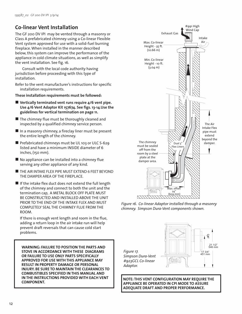
Co-linearVentInstallationTheGF200DVIPImaybeventedthroughamasonryorClassAprefabricatedchimneyusingaCo-linearFlexibleVentsystemapprovedforusewithasolid-fuelburningfireplace. When installed in the manner described below,thissystemcanimprovetheperformanceoftheapplianceincoldclimatesituations,aswellassimplifytheventinstallation.Seefig.16.
Consult with the local code authority having jurisdictionbeforeproceedingwiththistypeofinstallation.Refertotheventmanufacturer’sinstructionsforspecific
installationrequirements.Theseinstallationrequirementsmustbefollowed:
Verticallyterminatedventrunsrequire4/6ventpipe.Use4/6VentAdaptorKit157674.Seefigs.13-14. Use the guidelines for vertical termination on page 11.
The chimney flue must be thoroughly cleaned and inspectedbyaqualifiedchimneyserviceperson.
Inamasonrychimney,afireclaylinermustbepresentthe entire length of the chimney.
PrefabricatedchimneysmustbeUL103orULCS-629listedandhaveaminimumINSIDEdiameterof6inches,(150mm).
No appliance can be installed into a chimney flue serving any other appliance of any kind.
THE AIR INTAKE FLEX PIPE MUST EXTEND 6 FEET BEYOND THE DAMPER AREA OF THE FIREPLACE.
Iftheintakeflexductdoesnotextendthefulllengthof the chimney and connect to both the unit and the terminationcap,AMETALBLOCKOFFPLATEMUSTBECONSTRUCTEDANDINSTALLEDABOVETHEUNITPRIORTOTHEENDOFTHEINTAKEFLEXANDMUSTCOMPLETELYSEALTHECHIMNEYFLUEFROMTHEROOM.
Ifthereisenoughventlengthandroomintheflue,adding a return loop in the air intake run will help prevent draft reversals that can cause cold start problems.
Figure 16. Co-linear Adaptor installed through a masonry chimney. Simpson Dura-Vent components shown.
Figure 17. Simpson Dura-Vent #923GCL Co-linear Adaptor.
Max.offset 24”
(609mm)
TheAirIntakeFlexpipe must extend
beyond the damper.The chimney
must be sealed off from the
room by a steel plate at the
damper area.
#991HighWind Cap
ExhaustGasIntake AirMax.Co-linear
Height-35ft.(10.66m)
Min.Co-linearHeight-10ft.
(3.04m)
Dual3” FlexLiners
NOTE: THIS VENT CONFIGURATION MAY REQUIRE THE APPLIANCEBEOPERATEDINCPIMODETOASSUREADEQUATE DRAFT AND PROPER PERFORMANCE.
WARNING: FAILURE TO POSITION THE PARTS AND STOVE IN ACCORDANCE WITH THESE DIAGRAMS OR FAILURE TO USE ONLY PARTS SPECIFICALLY APPROVED FOR USE WITH THIS APPLIANCE MAY RESULT IN PROPERTY DAMAGE OR PERSONAL INJURY.BESURETOMAINTAINTHECLEARANCESTOCOMBUSTIBLESSPECIFIEDINTHISMANUALANDIN THE INSTRUCTIONS PROVIDED WITH EACH VENT COMPONENT.
��
�������������
�������������

13
139587_02 GF 200 DV IPI 5/9/14
Figure 18. Vent System through a masonry chimney using the Simpson Dura-Vent Chimney Conversion Kits. Drawing is for illustrative purposes only - DO NOT VENT TWO APPLIANCES INTO A SINGLE CHIMNEY.
VerticalTerminationCap
CapAdaptor
Support/WallThimble Cover
ExhaustGas
IntakeAir
Use Standard Simpson Dura-Vent
ProSeriesPipefrom stove to
thimble
4”FlexPipenot included
in kit
TheGF200DVIPIisapprovedforusewithcomponentsofSimpsonDuraVentChimneyKit46DVA-KMCand46DVA-KCTinamasonrychimneyoraKits46DVA-KCA,46DVA-KCB,and46DVA-KCCforprefabricatedsolidfuellisted chimneys.Theseinstallationrequirementsmustbefollowed:
Verticallyterminatedventrunsrequire4/6ventpipe.Use4/6VentAdaptorKit157674.Seefigs.13-14.
Usetheguidelinesforverticalterminationshownonpage 11.
Inmasonrychimney,afireclaylinerorlistedsteelliner,must be present the entire length of the chimney.
Chimneyheightshouldnotexceed20ft.(6.09m).
Thelinermusthaveaninsidedimensionof6”roundorgreater.
PrefabricatedchimneysmustbeUL103orULCS-629listedandhaveaminimumINSIDEdiameterof6inch-es,(150mm).PrefabricatedchimneysmustbelistedforthespecificSimpsonDura-VentChimneyConversionKitsnotedabove.
Masonry or Prefabricated Chimney Conversion
IMPORTANT NOTICEINTHEU.S.,THEUSEOFANEXISTINGCHIMNEYASAN AIR INTAKE IS NOT COVERED UNDER THE ANSI Z21.88-1999-CSA2.33-M99TESTMETHODSANDRESULTINGITS/WHIPRODUCTCERTIFICATION.THECODE AUTHORITY HAVING JURISDICTION MUST BECONSULTEDPRIORTOPROCEEDINGWITHTHISINSTALLATION METHOD.THIS INSTALLATION IS NOT APPROVED IN CANADA.

14
139587_02 GF 200 DV IPI 5/9/14
���������
HorizontalTerminationExhaust Restriction: Undernormalcircumstances,no
exhaustrestrictionisrecommended.Settherestrictionshutter to PositionA-fullyopen,fig.8,pg.9.
Anyhorizontalterminationmustfallwithintheshadedportionoftheventwindowmatrixshowninfig.9.
Useof4"x65/8"venthorizontallyterminated,requiresthattheSecondaryExhaustBaffleberemoved.Seefigs.21-22.
Horizontalterminationrequirements:1)Ifnoverticalrun,theminimumhorizontalrunis6in. 2)Ifnoverticalrun,themaximumhorizontalrunis48in. 3)Maximumverticalrunis20ft. 4)Withanyverticalrun,themaximumhorizontalrunis15ft. 5)Nomorethanfour45°ortwo90°Elbows
Thehorizontalterminationcapmustmaintaina3"clearancetoanyoverheadcombustibleprojections 21/2"orless.Itmustalsomaintain12"clearancefromprojectionsexceeding21/2".Seefig.24.
WallCut-outOpening:Aminimum10"X10"(250mmx250mm)squareholeisrequiredforproperpipeclearances through a combustible wall.
DO NOT FILL AIR SPACE WITH ANY TYPE OF INSULATION.
Anyhorizontalrunofventmustbelevelorhavea1/4in.riseforeveryfootofruntowardtheterminationcap. NEVERALLOWTHEVENTINGTORUNDOWNWARDFROMSTOVETOTERMINATION;DOWNWARDVENTRUNSTRAPHEATANDCAUSEHIGHTEMPERATURESTODEVELOPWITHINTHEVENTTHATCOULDSTARTAFIRE.
InstallaVinylSidingStandoff(SimpsonDura-Vent#950)betweentheventterminationandanexteriorwall covered by vinyl siding material to prevent potential heat damage to the siding.
Directventterminalsmaynotberecessedintoawallor siding.
Figure 19. Minimum vent for horizontal termination.
Figure 21. Use 1/2” (10 mm) socket to remove nut from Primary Baffle stud.
Figure 22. Use 1/4” (6 mm) socket driver to remove Primary Baffle from Secondary Baffle.
Secondary Baffle
PrimaryBaffle
PrimaryBaffle
Figure 20. 5/8 Vent - Maximum horizontal vent - no vertical run. 1/4 inch (6mm) rise per foot is required.
��������

15
139587_02 GF 200 DV IPI 5/9/14
Figure 23. Vent Terminal Clearances - ANSI Z21.88-2009, CSA 2.33-2009, and National Fuel Gas Code.
HorizontalTerminationClearance
Figure 24. Termination Clearance to overhangs.
�������
���������
�����������
A=Clearanceabovegrade,veranda,porch,deck,orbalcony:12inches(30cm)minimum.
B=Clearancetowindowordoorthatmaybeopened:**Min.9inches,U.S./*12inches(30cm)CAN. We recommend 12in. minimum to prevent condensation on the window.
C=Clearancetopermanentlyclosedwindow: **Min.9inches,U.S./*12inches(30cm)CAN We recommend 12 in. minimum to prevent condensation on the window.
D=Verticalclearancetoventilatedsoffitlocatedabovetheterminalwithinahorizontaldistanceof2feet(60cm)fromthecenterlineoftheterminal:18inches (46cm)minimum.
E=Clearancetounventilatedsoffit:12inches(30cm)minimum.
F=Clearancetooutsidecorner:**Min.9inches,U.S./*12inches(30cm)CAN.Westronglyrecommend12inches,particularly where windy conditions pevail.
G=Clearancetoinsidecorner:**Min.6inches,U.S./*12inches(30cm)CAN.Westronglyrecommend12inches,particularly where windy conditions pevail.
H=*Nottobeinstalledwithin15feet(4.5m)aboveame-ter/regulatorassemblywithin3feet(90cm)horizontallyfromthecenter-lineoftheregulator.
I=Clearancetoserviceregulatorventoutlet: 3feet(91cm)minimum.
J=Clearancetononmechanicalairsupplyinlettobuildingorthecombustionairinlettoanyotherappliance: 12inches(30cm)minimum.
K=Clearancetoamechanicalairsupplyinlet: **Min.3feet(91cm)aboveifwithin10feethorizontally,U.S./*6feet(1.83m)minimum/CAN
L=1 Clearance above paved sidewalk or a paved driveway locatedonpublicproperty:7feet(2.1m)min.
* InaccordancewithCSAB149InstallationCodes. **InaccordancewiththecurrentANSIZ223.1/NFFPA54,NationalFuel Gas Code. Note: Local Codes and Regulations may require different clearances.
1Aventshallnotterminatedirectlyaboveasidewalkordrivewaywhichislocatedbetweentwosinglefamilydwellingsandservesbothdwellings.2 Onlypermittedifveranda,porch,deck,orbalcony,isfullyopenonaminimumoftwosidesbeneaththefloor.*
M=Clearanceunderveranda,porch,deck,orbalcony: 12inches(30cm)minimum. 2
N=Clearancetopropanetankreliefvalveandfillerconnec-tion***: 5 feet (1.52 m) minimum to tanks not filled on site 10feet(3.05m)minimumtotanksfilledonsitefrombulktruck.
�
������������� ���������� ������������ �������������������� �

16
139587_02 GF 200 DV IPI 5/9/14
Tools required:• 1/2”openendedwrenchordeep-wellsocket,• TorxT20wrench• 1/4”socketdriverorspadescrewdriver• 7/16”open-endwrench.
Conversion Kit Contents:• 1,regulatortowerlabeledforeitherLPorNG• 2,regulatortowerscrews• 1,burnerorifice(1.20mm-LP/2.10mm-NG)• LabelA-tobecompletedandappliedto
the back of the stove• LabelB-applytothestove’sRatingPlate• Smallvalvelabel-applytovalvebody
Fuel ConversionTheGF200DVIPIgasstoveisshippedfromthefactoryequippedtoburnNATURALGASonly.IfPROPANEgasistobeusedasfuel,theappliancemustfirstbeconvertedforusingPropaneConversionKit157669includedwiththestove.UseNaturalGasConversionKit157670tochangeback for use with natural gas.
WARNING:THECONVERSIONKITISTOBEINSTALLEDBYAN AUTHORIZED JØTUL SERVICE TECHNICIAN IN ACCORDANCE WITH THE MANUFACTURER’S INSTRUCTION AND ALL CODES AND REQUIREMENTS OF THE AUTHORITY HAVING JURISDICTION. FAILURE TO FOLLOW THESE INSTRUCTIONS COULD RESULT IN SERIOUS INJURY OR PROPERTY DAMAGE. THE QUALIFIED AGENCY PERFORMING THIS WORK ASSUMES RESPONSIBILITYFORTHISCONVERSION.
IN CANADA:THECONVERSIONSHALLBECARRIEDOUTIN ACCORDANCE WITH THE REQUIREMENTS OF THE PROVINCIAL AUTHORITIES HAVING JURISDICTION AND IN ACCORDANCE WITH THE REQUIREMENTSOFTHECAN1-B149.1AND.2INSTALLATION CODE.
Figure 26. Loosen the wing nut and push the shutter stem fully to the rear to disengage the burner.
Figure 25. Tilt the burner skirt forward from the rear, then twist end first out through the door opening.
Figure 27. Use a 1/4” socket driver to remove two sheet metal screws to lift burner out of the firebox.

17
139587_02 GF 200 DV IPI 5/9/14
Fuel Conversion Procedure 1. Turn off gas supply to stove.2.RemovethestoveTopPlate.3. DisengagethetwoGlassFrameLatches and lift the
glass panel frame up and out of the stove. 4. Ifinstalled,removetheEmbersandLogSetusingcare
not to damage the fragile log parts.5.LiftouttheBurnerSkirt.Seefig.25.6.ReachunderthestoveandloosentheAirShutter
wingnut.Pulltheshutterstembacktoeaseburnerremoval.Seefig.26
7. LiftouttheBurnerPlatewith removal of two screws fromthefireboxfloor.Seefig.27.
8.CHANGETHEINTEGRATEDDUAL-FUELPILOTORIFICE: a) LoosentwosheetmetalscrewstopivotthePilot
Shieldoutofthewayasshowninfig.28. b) Usethe7/16”wrenchtojustloosenthepilothead
enoughtopushintheadjustmentslide.Seefig.29. LP : push tab to left (red LP indicator is exposed). NG: push tab to right
9.ChangetheBurnerInjector.Seefig.30.Usinga1/2”openendwrenchordeep-wellsocketremovetheburner orifice from its brass elbow housing and replace with the appropriate orifice supplied in the kit.
10.ReplacetheBurnerPlate.EngagetheburnertubewiththeAirShutterassembly.Besuretheburnerislevelandsecure it to the four support brackets with the screws previously removed.
11. Replace the Valve Regulator.UsingaTorxT-20screwdriver,removethescrewsfromthefrontoftheregulator. Removetheregulatorcomponentsandreplace with the one from the conversion kit. See fig. 31.
12. Install the identification labels to the stove so that they can be seen by any person who may be servicing the stove. LabelA:applytobackofstove LabelB:applytotheratingplateattachedtothebackofthe stove. SmallConversionLabel:applytovalve.
13.Reassemblethestove,applygastothesystemandcheck for leaks using a soapy water solution or digital gas detector.
NEVER USE AN OPEN FLAME TO CHECK FOR GAS LEAKS.
Figure 28. Use a 1/4” socket driver to loosen two screws and pivot the Pilot Shield out of the way.
��
Figure 30. Replace the Burner injector.
Figure 29. Integrated dual-fuel pilot orifice- LP position shown.
PilotShield
Figure 31. Regulator tower replacement.
Diaphragm
RegulatorTower
ValveBody

18
139587_02 GF 200 DV IPI 5/9/14
����
Gas Supply ConnectionNOTE:Ifappropriate,installtheoptionalforcedairblowerbeforeconnectingthegasline,topreventclearance interference between the two.
The gas supply line connection is made to the left sideofthevalve.Thegassupplylineshouldbe3/8”nptwitha1/2”diametersupply,ortheappropriatesizetoprovide sufficient gas pressure to the valve regardless of the input setting.
TheuseofFlexibleGasApplianceConnectorsisacceptableinmanyareasintheU.S.However,Canadianmethods vary depending on local code.
ALLINSTALLATIONSMUSTCOMPLYWITHLOCALCODEORINTHEABSENCEOFLOCALCODE,MUSTCOMPLYWITHTHEMOSTRECENTEDITIONOFTHENATIONALFUELGASCODEANSIZ223.1/NFPA54ORCAN-B149.
Allcodesrequireagasshut-offvalve(gascock)andunion,tobeinstalledinthesupplyline,andinthesameroom as the appliance. This allows for the disconnection of the stove for servicing and maintenance. See fig. 33.
AT-HANDLEGASCOCKISREQUIREDIN MASSACHUSETTSTOCOMPLYWITHCODE248CMR.
Securealljointstightlyusingappropriatetoolsandsealing compounds. For propane units be sure to use com-pounds that are propane resistant. Turn on gas supply and test for gas leaks using a soapy water solution. Never use an open flame to check for leaks.
Leak test:1. Mixa50-50solutionofwateranddish
soap.2. Lightappliance-seelightinginstructions
on the inside back cover of this manual or on the stove’s rating plate.
3. Brushorsprayalljointsandconnectionswith the soapy water solution.
4. Ifbubblesappearatanyconnectionorseamoragasodorisdetected,imme-diately turn gas control knob to the OFF position.
5. Tightenorreconnecttheleakingjointand retest for any gas leaks.
Figure 33. Supply valve connection fittings.
���������������������� �������
���������������
���������������������������
����������
��������
������������������
���������� ������
������� ���������
�������� �
FuelConversion,cont’d.15.Correctgaspressureisessentialforefficientandsafe
operation of this appliance. Use a manometer to check pressuresasspecifiedintheGasPressuresectionofthismanual(page19).
16.AdjusttheAirShutter. You will need to position the shuttertoprovideagas/airmixturethatwillachievethe best flame picture with your particular installation.
Pushingthestembackwillrestrictair,whilepushingit forward will open the shutter and increase air. With someexperimentation,youwillfindtheshutterposi-tion that works best for your installation. Start at the followingpositionsfortheappropriatefuel: Propane-1/8”(4mm) Naturalgas-1/16”(2mm)
ALWAYSREFERTOTHELIGHTINGINSTRUCTIONSONTHEINSIDEBACKCOVEROFTHISMANUALWHENLIGHTINGYOURSTOVE.
Figure 32. Pull the shutter forward to increase primary air. Push back to restrict air.

19
139587_02 GF 200 DV IPI 5/9/14
Gas PressureCorrect gas pressure is essential for efficient and safeoperationoftheGF200DVIPIgasstove.Itisimportant that the correct pressure is established atthetimeoftheinstallation.Propergaspressureprovides a consistent flow of gas to the appliance and is instrumental in checking for gas leaks.
Pressure Test: Attachamanometertotheappropriatetestpointonthevalve.Seefig.34.Thegauge connections are located on the front of the valve. Connectionsareidentifiedby:
A-forManifoldPressure (the amount of gas that is coming out of the valve to the burner.)
B-forInletorSupplyPressure (the amount of gas coming to the valve.)
ALWAYS TEST PRESSURES WITH VALVE CONTROL KNOBSETONHIGH.
INLETGASPRESSURES (inches water column)
MIN MAX NATURALGAS 5.0 7.0 PROPANE 12.0 14.9
The appliance and its appliance main gas valve must be disconnected from the gas supply piping system during any pressure testing on that system attestpressuresinexcessof1/2psig(3.5kPa).
The appliance must be isolated from the gas supply line by closing its individual manual gas shut-offvalve(gascock)duringanypressuretestingofthegassupplypipingsystemthatisequaltoorexceedspressuresof1/2psig(3.5kPa).
MANIFOLDPRESSURES(inches water column)
MIN MAX
NATURALGAS 1.1 3.8 PROPANE 2.9 11.0
HighAltitudeAdjustmentThe decreased atmospheric pressure of higher altitudesaffectsheatvalueofgaseousfuels.Mostgas suppliers derate the gas intended for use at elevationsabove2000feet.Checkwithyourgassupplierbeforeperformingderateadjustmenttotheburner.Ifthegassupplierdoesnotderatefuels,installHighAltitudeAdjustmentKit157675forPropaneandKit157676forNaturalgas.
U.S & Canada per ANSIZ21.88-2009•CSA2.33-2009,CAN/CGA2.17At610-1370meters(2000-4500ft.),theorificesizeis#46forNaturalGasand#56forPropane.Seedataplateforadditionalinformation.Athigheraltitudes,consult the local gas distributor or the authority havingjurisdictionforproperratingmethods.Iftheinstallermustconverttheunittoadjustforvaryingaltitudes,theinformationlabelmustbefilledoutand applied to the appliance at the time of the conversion.
INSTALLER:Fillouttheappropriateinformationand apply the high altitude conversion label provided totheratingplateontheappliance.Seefig.35.
Derating Procedure• FollowthestepsforBurnerInjectorreplacement
intheFuelConversionprocedureonpages17-18.Usetheinjectorsuppliedwiththeadjustmentkit.Detailedinstructionsarealsoincludedinthekit.
• Conductgasleakandgaspressuretestsasde-tailed the preceding section.
• Conductsystemcheckandflamepictureadjust-mentsasspecifiedonpages22-23.
Figure 35. High Altitude Conversion Label.
This appliance has been converted for use at an altitudeof___________.OrificeSize:__________ManifoldPress._______InputBtu/Hr._________FuelType___________Date:___/___/___Convertedby:_____________Cetappreeilaétéconvertiau_____Injecteur_____ Pressionàlatubulured’alimentation___________Déoitcalorifique___________
Cetappareilestequippépourgaznatureldesaltitudescompriesentre0et4500pieds(0-1372m)seulement.
Figure 34. Pressure test points.B
A
20
139587_02 GF 200 DV IPI 5/9/14
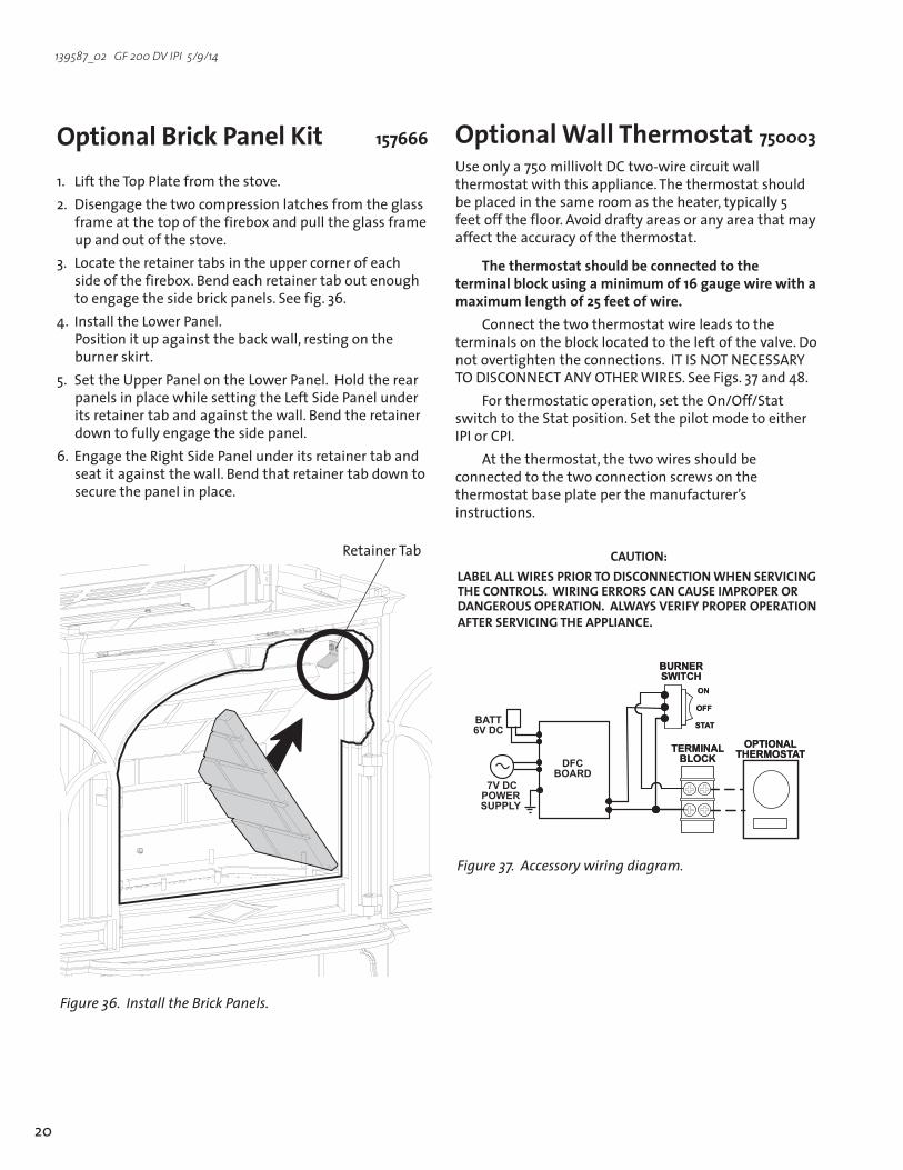
OptionalBrickPanelKit 157666
1. LifttheTopPlatefromthestove.2. Disengagethetwocompressionlatchesfromtheglass
frameatthetopofthefireboxandpulltheglassframeup and out of the stove.
3. Locatetheretainertabsintheuppercornerofeachsideofthefirebox.Bend each retainer tab out enough toengagethesidebrickpanels.Seefig.36.
4. InstalltheLowerPanel. Positionitupagainstthebackwall,restingontheburner skirt.
5. SettheUpperPanelontheLowerPanel. HoldtherearpanelsinplacewhilesettingtheLeftSidePanelunderits retainer tab and against the wall. Bend the retainer down to fully engage the side panel.
6.EngagetheRightSidePanelunderitsretainertabandseat it against the wall. Bend that retainer tab down to secure the panel in place.
RetainerTab
Figure 36. Install the Brick Panels.
Optional Wall Thermostat 750003Useonlya750millivoltDCtwo-wirecircuitwallthermostat with this appliance. The thermostat should beplacedinthesameroomastheheater,typically5feetoffthefloor.Avoiddraftyareasoranyareathatmayaffect the accuracy of the thermostat.
The thermostat should be connected to the terminalblockusingaminimumof16gaugewirewithamaximumlengthof25feetofwire.
Connect the two thermostat wire leads to the terminalsontheblocklocatedtotheleftofthevalve.Donot overtighten the connections. IT IS NOT NECESSARY TO DISCONNECT ANY OTHER WIRES.SeeFigs.37and48.
Forthermostaticoperation,settheOn/Off/Statswitch to the Stat position. Set the pilot mode to either IPIorCPI.
Atthethermostat,thetwowiresshouldbeconnected to the two connection screws on the thermostat base plate per the manufacturer’s instructions.
CAUTION:LABELALLWIRESPRIORTODISCONNECTIONWHENSERVICINGTHE CONTROLS. WIRING ERRORS CAN CAUSE IMPROPER OR DANGEROUS OPERATION. ALWAYS VERIFY PROPER OPERATION AFTER SERVICING THE APPLIANCE.
Figure 37. Accessory wiring diagram.
������������������
������������
��
���
����
��������
������������
���������������
������������������
������������
��
���
����
������������
��������

21
139587_02 GF 200 DV IPI 5/9/14
Log Set InstallationBrickKitNote:InstalltheoptionalBrickPanelKit157666beforeinstallingthelogset.Seepage20ortheinstructions provided with that kit.TheGF200DVIPIlogsetmustbeinstalledbeforeoperatingtheburner.Thelogsetincludesfourlogpieces,packagedinsidethefirebox.Aquantityofemberstonesisincludedwiththelogset.Placethelogsinsidethefireboxasillustratedinfigs.38-42. WEAR GLOVES AND HANDLE THE LOG PARTS CAREFULLY.
#157668LogSetIdentification #1 LeftRear 225447
#2 RightRear 225448 #3 BurnerLog 225450 #4 “Y”Log 225449 #5 EmberStones 225451
The ember stones realistically simulate glowing coals when the burner is operating. These should be spread sparsely over the burner plate and around the logs. Use a pencil to position the stones so as not to block the burner plate porting.
TOINSUREPROPERBURNERFUNCTION,DONOTOBSTRUCTTHEPILOTASSEMBLY,BURNERSKIRTOPENINGS,ORBURNERPLATEPORTINGWITHEMBERSTONES.KEEPEMBERSAWAYFROMTHEPILOTCARRY-OVERPORTS.
You do not need to use all of the ember stones.Withsomeexperimentation,youwillfindthearrangementandquantityofembersthatworksbest.Dependinguponthecharacteristicsofyourinstallation,itispossiblethat too many ember stones can promote sootingonthelogs.Adjustthequantityofember stones as appropriate to maintain the best overall flame picture and burner performance.
IMPORTANT
Figure 38. Engage the Left Logs with the two pins on the back shelf.
Figure 39. Engage the Right Logs on the other two pins on the back shelf.
Figure 40. Engage the Front Log with the two center pins.
1
2
3

22
139587_02 GF 200 DV IPI 5/9/14
4
Figure 43. Proper pilot flame appearance relative to burner carry-over porting.
Figure 41. Position the Middle Cross Log as shown.
Figure 42. Place Ember Stones loosely over the burner plate. DO NOT OBSTRUCT THE GAS PORTING. SEE FIG. 43. Use the supplied rock wool sparingly.
Keepemberstonesclearofcarry-overports
5
System Check1.PURGINGTHEGASLINE:Whenlightingtheappliance
forthefirsttime,itwilltakeafewmomentstoclearthegaslineofair.Oncethispurgeiscomplete,theappliance will operate as described in the lighting instructions.Fromacoldstart,itmaybehelpfultoletthepilotlightburninCPImodefor10-15minutestoestablishpositivedraft,beforeturningtheburneron. See the procedure on the inside back cover of this manual.Subsequentburnerstartswillnotrequirepurging the gas line unless the supply line is shut off.
2.PILOTFLAME:YoucanmonitorthepilotflamelocatedundertheRearLog.Seefig.43.Thepilotflameshouldbesteady-notliftingorfloating.Theflameshouldbeblueincoloraroundthepilothood,withtracesofyellow toward the outer edges.
Thepilotflameshouldengulfthetop1/8”oftheflamesensor.Thepilotflameshouldprojectfrontpilothoodporttowardtheburnerplatecarry-overports.Adjustthepilotflameusingtheadjustmentscrew to the left of the valve regulator.
3.MANUALBURNERADJUSTMENT:Thisstoveisequippedwithavariablegascontrolvalvethatallowsmanualadjustmentoftheflameheightandheatoutput.Toadjusttheflameintensity,rotatetheregulator knob. Flameheightwilladjustapproximately50%betweentheLOWandHIGHsettings.Seefig.46,page23.
NOSMOKEORSOOTSHOULDBEPRESENT.CHECKLOGPLACEMENTIFANYSOOTORSMOKEISPRESENT.IFSOOTORSMOKEPERSISTS,THEAIRSHUTTERMAYNEEDTOBEADJUSTED.
SeeFlameAppearance/AirShutterforairshuttersettingsandadjustments.Note:Themoreoffsetsthereareintheventsystem,thegreatertheneedforanairshutteradjustment.
WARNING: AIRSHUTTERADJUSTMENTSSHOULDONLYBEPERFORMEDBYAQUALIFIED,PROFESSIONALSERVICE TECHNICIAN.
Figure 44. Manual flame regulation.
RegulatorPilotAdjustment

23
139587_02 GF 200 DV IPI 5/9/14
FlameAppearance/AirShutterAdjustmentTheAirShuttermaybeadjustedtoprovidethebestflamepicture for your specific installation. The factory setting for Naturalgasis1/16”(1.5mm)open.ForPropane,theinitialrecommendedsettingis1/8”(3mm)open.
Too large an air opening -theappliancewillgenerateaflamethatisblueandtransparent,oran“anemic”flame.
Too small an air setting -theappliancewillgeneratevery long yellow flames resulting in soot. Sooting producesblackdepositsonthelogs,ontheinsidewallsoftheappliance,andpotentiallyontheexteriorterminationcap. Sooting is caused by incomplete combustion in the flames and lack of combustion air entering the air shutter opening.
Toadjusttheairshutter:1. Reachunderthestoveandloosenthewingnut.See
fig.45.Slidethewingnutstudforwardtoopentheairshutterandbacktoprovidelessair.Makeadjustmentsin1/16”(1.5mm)increments.
2. Allowthestovetoburnfor30minutesontheHIGHsetting,observingtheflamecontinuously.Iftheflameappearsweak,slow,orsooty,repeattheprocessdescribed above until the flame is as desired.
3. Tighten the wingnut to secure the shutter at the desired setting.
WARNING: AIR SHUTTER ADJUSTMENTS SHOULD ONLY BEPERFORMEDBYAQUALIFIEDPROFESSIONALSERVICETECHNICIAN.
����
Figure 45. Loosen the wing nut to adjust the air shutter. Min. Opening NG: 1/16” (1.5 mm) Factory Setting Min. Opening LP: 1/8” (3 mm)
Figure 46. Normal flame picture.

24
139587_02 GF 200 DV IPI 5/9/14
OperationImportant Notes
Check the build date on the shipping crate label.Ifithasbeenmorethan6monthssincethebuilddate,bepreparedtoreplacethe DFC batteries.
1. Forthefirstseveralhoursofoperation,itiscommonto detect some odor as the metal and manufacturing materials cure under heat. This condition is temporary and can be alleviated by allowing plenty of fresh air to circulate through the area.
2. Condensation may develop on the glass upon each lightingoftheappliance.This“fog”willdisappearasthe glass heats.
3. IMPORTANT:Itwillbenecessarytocleantheglassafterthefirstfewfires.Awhitepowderyresiduewillbeevidentwhichresultsfromtheburnermediacuring.Useanon-abrasivehouseholdglasscleanerandwarmwater.IFTHEGLASSISNOTCLEANED,THISRESIDUECANCAUSETHEGLASSTOBECOMEPERMANENTLYETCHED.DONOTUSEAMMONIA-BASEDCLEANERS.
4. Keepthecontrolcompartmentsandareaundertheappliancefreeofdust.Alwayskeeptheapplianceareaclearandfreefromcombustiblematerials,gasolineandotherflammableliquids.
5. Thisappliancecanbeoperatedwithacontinuouslyburningpilotflame.Exercisecautionwhenusinghousehold products containing combustible vapors.
6. CAUTION: DO NOT OPERATE THIS APPLIANCE WITH THEGLASSPANELREMOVED,CRACKEDORBROKEN.REPLACEMENTOFTHEGLASSSHOULDBEDONEBYA LICENSED OR QUALIFIED SERVICE PERSON. USE ONLYREPLACEMENTGLASSPROVIDEDBYYOURAUTHORIZEDJØTULDEALER.NEVERSUBSTITUTEANYOTHER TYPE OF GLASS. REMOVE GLASS ONLY FOR ROUTINE SERVICE. ALWAYS HANDLE GLASS CAREFULLY.
WARNING: READ AND UNDERSTAND ALL OPERATING INSTRUCTIONSBEFOREATTEMPTINGTOOPERATETHIS APPLIANCE. DO NOT ALLOW ANYONE TO OPERATE THIS APPLIANCE WHO HAS NOT READ AND UNDERSTOOD THESE INSTRUCTIONS.
WARNING: SEVEREINJURY.THISAPPLIANCECANBESETTOOPERATETHERMOSTATICALLY.BEAWARETHATTHEFIREPLACEMAYBEVERYHOTEVENWHENTHEBURNERISNOTAPPARENTLYOPERATING. KEEP CHILDREN AWAY FROM THE APPLIANCE.
WARNING:OBSERVECAUTIONNEARTHEGLASSPANEL.THEGLASSMAYSHATTERIFSTRUCKBYANOBJECT. ALWAYS HANDLE THE GLASS PANEL WITH CARE.
DFCBatteryReplacement1. Switch Burner to OFF and disconnect power to the stove.2.Accessthebatteryboxfromunderthegasvalve.See
fig.47and48a.DisengagethewireharnessfromtheretainerslotonthebackoftheDFCbracket.Disengagethebatteryboxfromthehook&looptape.
3.Slidethecoverplatebacktoopenthebox.Installfour,1.5vAAbatteriesandreattachtheboxtotheundersideofthevalve.Re-engagethewireswiththeretainerslot.
4. Reconnectpowertothestove.
Figure 47. Battery box to DFC wire harness connection. Tuck harness up into the slot on the back of the DFC module.
Wire Retainer
Slot
BatteryBoxHarness
DFC Harness
DFC Module Bracket

25
139587_02 GF 200 DV IPI 5/9/14
OperationFamiliarizeyourselfwiththecontrolsoftheGF200DVIPIandbesurethatanyoneelseusingtheapplianceisalso familiar with the controls and operation procedures. AlwaysfollowtheLightingInstructionsontheinsidebackcover of this manual and also located on the inside of the ControlsAccessDoor.
Thisapplianceisequippedwithanignitiondevicethat lights the pilot automatically. Do not try to light the pilot by hand.
LocatetheBurnerControlswitchesatthetopleftsideoftherearshroud.Seefig.48.1. Set the Burner switch to OFF. Open the main gas
supply line to the stove.2.ConnecttheAC/DCPowerAdaptortotheterminal
onthebackoftheDFCboardbracket.Seefig.48a.Connecttheadaptorplugto110VAChousecurrent.
3. Ifawallthermostatisused,setittothelowesttemperature.
4. SetthePilotMode: •CPI for continuous pilot operation• IPI for intermittent operation.
5. SettheBurnerSwitchtoON. The pilot will light.ON/OFF-useformanualcontroloftheburner.STAT -usewithanoptionalwallthermostat.
6. FlameintensitycanbeadjustedmanuallybyturningtheValveRegulatorknobshowninFig.48a.
Figure 48. Burner controls location, viewed from above stove.
���������������������������
����������������������������
��� ����������
����������
����������������
����������������
��������������������
���������������������
���������������������������������������� ���������
Figure 48a. Valve and Blower Controls.
���
���
��
����
���
������
���
��

26
139587_02 GF 200 DV IPI 5/9/14
Glass CareClean the glass only when necessary. Wipe the surface withaclean,dampened,softcloth.Followwithadry,softtowel. Take care not to scratch the glass surface.WARNING: DONOTUSEABRASIVECLEANERSONTHEGLASS. NEVER CLEAN THE GLASS WHEN IT IS HOT. DONOTUSEAMMONIA-BASEDCLEANINGSOLUTIONS.
Gasket InspectionIt is important that the glass gasket be inspected at least annually.Examinetheribbongasketforsignsofdete-rioration and make sure the gasket has a positive seal. Replacethegasketifnecessary.Refertothereplacementparts list on page 33.
FORREPLACEMENT,USEONLYJØTULCERAMICGLASSPN220576.DONOTUSEANYOTHERTYPEOFGLASSWITH THIS APPLIANCE.
Figure 50. Wrap the gasket around the glass panel.
MaintenanceYourJøtulGF200DVIPIcomponentsanditsventingsystem should be inspected before use and at least annuallybyaqualifiedservicetechnician.IMPORTANT: ALWAYS TURN OFF THE GAS SUPPLY AND DISCONNECTPOWERFROMTHEAPPLIANCEBEFOREANYSERVICE WORK IS PERFORMED.
Annual Cleaning Vent SystemTheentireventsystem,includingthechimney,shouldbe inspected and cleaned every year. If the intake and exhaustventingisdisassembledforanyreason,itshould be reassembled and sealed according to the manufacturer’s instructions provided at the initial installation.
BurnerSystemPeriodicallyinspectthefirebox,valvecompartment,convectionairwaysandoptionalblowertoBECERTAINTHATTHEFLOWOFCOMBUSTIONANDVENTILATIONAIRISUNOBSTRUCTED.
Thefireboxandvalvecompartmentshouldbevacuumed annually to remove any dust and debris. Use a soft brush attachment and handle the logs carefully astheyarefragile.Vacuummorefrequentlyiftherearepets in the home.
The pilot assembly should be inspected and cleaned annually by a qualified technician. Any component showingcorrosionshouldbereplaced.
Glass Panel or Gasket Removal1. LifttheTopPlateoffofthestove.2. ReleasethetwoGlassFrameLatches.Pulleachlatch
handle forward forward to disengage the latch from the notches in the glass frame.
3. Lifttheglassframeallthewayupandoutofthetopofthestove.Laythisassemblyonaflatsurface,protectingthe frame from scratches using a blanket or towel.
4.Theglasspanelisheldinplacebyfourtabsontheframe. Use a screwdriver or small pliers to pry these up enoughtoreleasetheglasspanel.Seefig.49.
5. Removetheoldgasketmaterial.
Glass Panel or Gasket Replacement1. Wrap the new gasketing material evenly around the
edgeoftheglass,peelingbacktheprotectivestriptoexposetheadhesiveasyougo.Seefig.50.Presstheadhesivesidedownontotheglasssurface.Donotstretch the gasket.
2.Placethegasketedglasswithintheframeandcarefullybend each of the retainer tabs back to secure the glass intheframe.Thereplacementglasskit155599includes4compressionclipsforuseincaseatabshouldbreak.
Figure 49. Bend the retainer tabs back enough to release the glass panel.

27
139587_02 GF 200 DV IPI 5/9/14
OptionalVariableSpeedBlower 155631
CONNECT THE GAS SUPPLY TO THE STOVEBEFOREINSTALLINGTHIS
BLOWER.USEA90°ELBOWOFFTHEGAS VALVE TO CREATE ADEQUATE
GAS LINE CLEARANCE.
THISBLOWERMUSTBEELECTRICALLYGROUNDED IN ACCORDANCE WITH LO-CALCODESOR,INTHEABSENCEOFLOCALCODES,WITHTHECURRENTANSI/NFPA70,NATIONALELECTRICALCODEORCSAC22.1-CANADIAN ELECTRICAL CODE.
THISUNITISSUPPLIEDWITHATHREE-PRONG (GROUNDING) PLUG FOR PRO-TECTION AGAINST SHOCK HAZARD AND SHOULDBEPLUGGEDDIRECTLYINTOAPROPERLYGROUNDEDTHREE-PRONGRECEPTACLE. DO NOT CUT OR REMOVE THE GROUNDING PRONG FROM THE PLUG.
ALWAYS DISCONNECT THE POWER SUPPLY WHEN PERFORMING ANY SERVICE ON THE FIREPLACE INSERT.
Contents 1. Blower 2. SnapstatWireHarness 3. ControlBox 4. SnapstatBracket 5. RheostatKnob 6. Snapstat 7. M6FlangeNuts,(2) 8. M6x12HexBolts,(2) 9.#8x1/2”Sheetmetalscrew,(4)
ToolsRequired •1/4”socketdriver •10mmsocketdriverorwrench
Figure 51. Blower Kit Components
BlowerInstallation1. Unpack and check the contents of the blower kit. There
isasteelbracketthatisnotusedwiththeGF200stove. Contact your dealer if any damage is evident or partsaremissing.Seefig.51.
2. AttachtheControlBoxtothelowerpairofholesontheSnapstatBracketwithtwo#8x1/2”sheetmetalscrewsasshowninfigs.51and52.
3. AttachtheControlBoxassembly to the studs located underneaththestoveinthemiddleofthefireboxfloorusingtwoM6hexnutsanda10mmsocketdriverorwrench.Seefig.52.
4.UsetwoM6hexnutstoattachtheBlowertothemounting holes at the rear of the stove bottom plate.
5. Connectthepowercordto110AChousecurrent.
1
2
6
8
75 3
4UseLowerHolesfor
GF200DVII
9
7

28
139587_02 GF 200 DV IPI 5/9/14
Figure 52. 155631 Blower Kit Components used for GF 200 DV IPI Lillehammer.
����������
��
������
�����������
�
��������
��
��
������
�������������������
��
��
��
��
��
BlowerOperationThevariable-speedblowerwillenhanceheatcirculationaroundthefireboxandoutintotheroom.Thebloweriscontrolled by a heat activated switch (snapstat) that will functiononlywhenthecontrolswitchisintheAUTOsetting.Afterthefirehasbeenburningforatime,thesnapstat will react to the heat and activate the blower. Fanspeedmaybemanuallyadjustedwiththerheostatknob.Iftheburnerturnsoff,theblowerwillbeshutoffautomatically as the stove cools down.
Ifautomaticblowercirculationisnotdesired,placetheblowercontrolswitchintheMANUALposition.Thatwilloverridethesnapstat,allowingtheblowertoruncontinuously.
CAUTION:LABELALLWIRESPRIORTODISCONNECTIONWHENSERVICING CONTROLS. WIRING ERRORS CAN CAUSE IM-PROPER AND DANGEROUS OPERATION.VERIFY OPERATION AFTER SERVICING.
ATTENTION:AUMOMENTDEL’ENTRENTIENDESCOMMANDES,ETIQUIETEZTOUSLEFILSAVANTLEDEBRANCHEMENT.ESERREURSDECEBLAGEPEUVENTENTRATUNFONC-TIONNEMENT INADEQUAT ET DANGEREUX.
Figure 53. GF 200 DV IPI Blower Wiring Diagram.

29
139587_02 GF 200 DV IPI 5/9/14
Figure 53. GF 200 DV IPI Blower Wiring Diagram.
BatteryPack Four,1.5vAA
CPI/IPI Switch SPDT
Burner Switch SPST
DCPowerSupply
Figure 54. GF 200 DV IPI Proflame 1 Components
Proflame 1 DFC Wiring Diagram
Appendix
Mobile Home InstallationTheGF200DVIPIcanbeinstalledforuseinamobilehomeintheU.S.andCanadaprovided:1. The stove is secured to the floor of the mobile home.
UseJøtulFloorBracketKit#750304.2. Provisionmustbemadetosecureanelectricalground
between the stove and the mobile home chassis.3. ThestoveisinstalledinaccordancewithTitle24CFR,
Part3280-ManufacturedHomeConstructionandSafetyStandard,intheU.S.InCanada,complywithCSAZ240.4,GasEquippedRecreationalVehiclesandMobileHousing.
4. Alwayscontactyourlocalofficialsaboutinstallationrestrictionsandrequirementsinyourarea.
THISAPPLIANCEMAYBEINSTALLEDASANOEMINSTALLATIONINAMANUFACTURED(MOBILE)HOMEANDMUSTBEINSTALLEDINACCORDANCEWITHTHE MANUFACTURER’S INSTRUCTIONS AND THE MANUFACTURED HOME CONSTRUCTION AND SAFETY STANDARD,TITLE24CFR,PART3280.THISAPPLIANCEISONLY FOR USE WITH THE TYPE OF GAS THAT IS INDICATED ON THE STOVE’S RATING PLATE. A GAS CONVERSION KIT IS PROVIDEDWITHTHEGF200DVIPIGASSTOVE.
THISAPPLIANCEMAYBEINSTALLEDINANAFTERMARKETPERMANENTLYLOCATED,MANUFACTURED(MOBILE)HOME,WHERENOTPROHIBITEDBYLOCALCODES.
CET APPAREIL PEUT ETRE INSTALLE DANS UN MAISON PREFABRIQUEE(MOBILE)DEJAINSTALLEEADEMEURESILES REGLEMENTS LOCAUX LE PERMETTENT. CET APPAREIL DOIT ETRE UTILISE UNIQUEMENT AVEC LES TYPES DE GAS INDIQUES SUR LA PLAQUE SIGNALETIQUE. NE PAS L’UTILISER AVEC D’AUTRES GAS SAUF SI UN KITDE CONVERSION CERTIFIE EST INSTALLE.

30
139587_02 GF 200 DV IPI 5/9/14
GF 200 DV IPI LillehammerIllustratedPartsBreakdown
CastIronParts MatteBlackBrownMajolica Paint Enamel1. TopCasting 10390692 103906472. SidePanel 10390792 103907473. FrontPanel* n/a n/a4. BottomPlate 10390092 103900475. Leg,6” 10195292 101952476. LeftDoor* n/a n/a7. RightDoor* n/a n/a *FrontAssembly 15592392 156384 includesFront,Doors,andHingePins
�
�
�
�
�
�
�
�
�
����
��
��
���
��
8. HingePin,(4) ............................................................................ 1259609. FenderWasher,M6(4) .......................................................... 12000410. Bolt,M6x20,(4) .........................................................................11711711. Bolt,M6x10HexHdFlange ...................................................996212. DoorCatch ...............................................................................220919
Figure 55. Exterior cast iron parts.
ReplacementLogSetParts/Seepgs.21-22.No. PartNo. Description
1 225447 LeftRearLog
2. 225448 RightRearLog
3. 225450 BurnerLog
4. 225449 “Y”Log
5. 225451 EmberStones
6. 157668 CompleteLogSet

31
139587_02 GF 200 DV IPI 5/9/14
No. PartNo. Description
1. 117917 Screw,#8x1/2”SLBlkOxide
2. 117921 Screw,PanHdPhM4x12mmBlkOxide
3. 117922 Nut,HexM4DIN934PLAIN
4. 117975 Nut,WingM6,Zinc
5. 117999 Screw,SLSMATypeB#8x3/8Zinc
6. 118029 Washer,Fender.250x1.50dia.
7. 118033 Bolt,M6x130HexHd
8. 118039 Spacer,.375ODx1.188
9. 118040 Spacer,ControlDoorHinge.375ODx3.172
10. 118214 Screw,#8x1/4”Taptite
11. 118257 Hook&LoopTape,1”Wide,Self-adhesive
12. 129154 TerminalBlock,2Pole77Series
13. 22093192 ControlDoorGF200DVIPI
14. 221185 Orifice,1.20mm
225441 Orifice,2.1mm
15. 222280 Gasket,Drop-inOrificeHolder
16. 222292 Elbow,90deg,Brass3/8NTPx3/8”dia.flare
Figure 56. GF 200 DV IPI Valve Assembly and DFC Components.
No. PartNo. Description
17. 222924 Proflame1IPIIgnitionBoard
18. 223231 OrificeHolder,Drop-inAssembly
19. 224262 BatteryBoxw/Cover
20. 224952 InstructionLabel,ControlDoor-GFIPISeries
21. 224972 Valve,NG,ProflameManual,50%TD,SIT
22. 225088 Bracket,DFC
23. 225089 TerminalBlockBracket
24. 225432 ValveBracket
25. 225433 WireRetainerBracket
26. 157683 WireHarness,Proflame1,Replacement
27.* 225422 AC/DCAdapter,HighTemp-7V
���
�������
���
���
������
���
���
* not illustrated
32
139587_02 GF 200 DV IPI 5/9/14
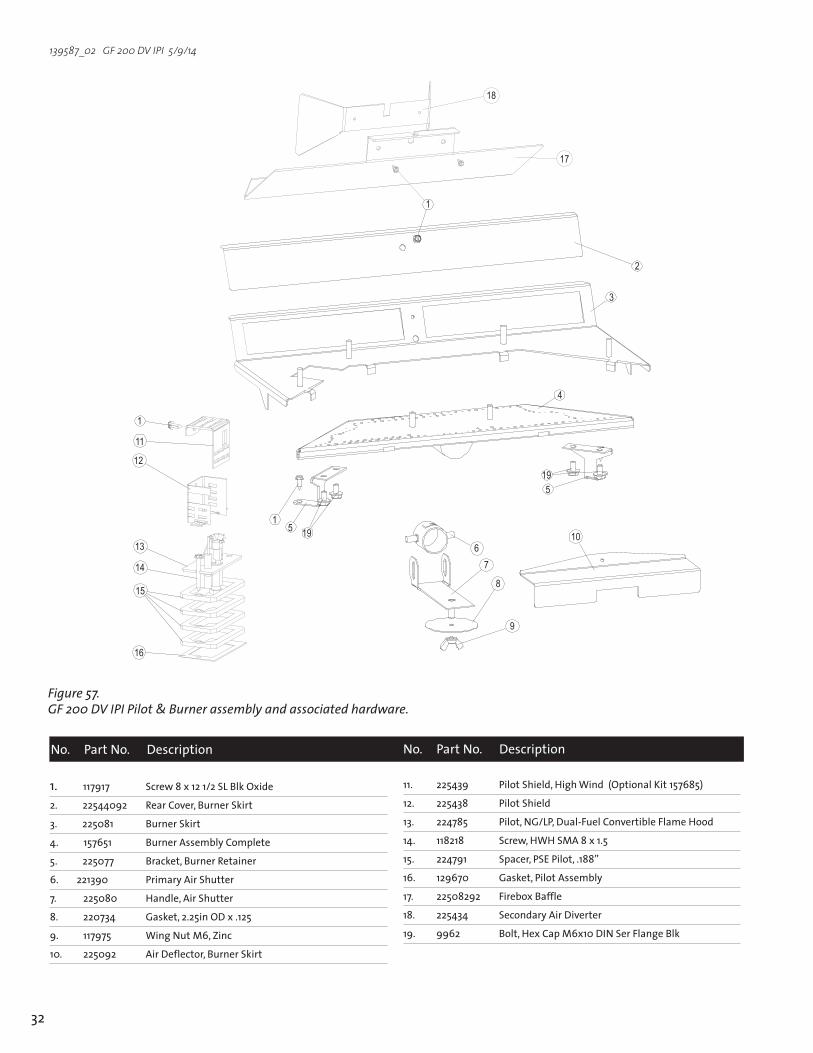
1. 117917 Screw8x121/2SLBlkOxide 2.22544092 RearCover,BurnerSkirt
3.225081 BurnerSkirt
4.157651 BurnerAssemblyComplete
5.225077 Bracket,BurnerRetainer
6.221390 PrimaryAirShutter
7. 225080 Handle,AirShutter
8. 220734 Gasket,2.25inODx.125
9. 117975 WingNutM6,Zinc
10. 225092 AirDeflector,BurnerSkirt
11. 225439 PilotShield,HighWind(OptionalKit157685)
12. 225438 PilotShield
13. 224785 Pilot,NG/LP,Dual-FuelConvertibleFlameHood
14. 118218 Screw,HWHSMA8x1.5
15. 224791 Spacer,PSEPilot,.188”
16. 129670 Gasket,PilotAssembly
17. 22508292 FireboxBaffle
18. 225434 SecondaryAirDiverter
19. 9962 Bolt,HexCapM6x10DINSerFlangeBlk
No. PartNo.Description No. PartNo.Description
Figure 57. GF 200 DV IPI Pilot & Burner assembly and associated hardware.
��
�
��
��
��
��
��
�� ��
�
��
�
�
�
���
�
�
�
�
��
��

33
139587_02 GF 200 DV IPI 5/9/14
Figure 59. GF 200 DV IPI Glass Assembly
GF 200DVIPIAccessoriesDescription PartNo.
RemoteControl 224910
WallThermostat 750003
BlowerKit 155631
Screen 155641
BrickPanelKit 157666
LongLegKit(81/4”)/MatteBlack 154929
LongLegKit(81/4”)/BrownMajolicaEnamel 351149
LegLeveler 156096
FuelConversionKit,Propane 157669
FuelConversionKit,NaturalGas 157670
HighAltitudeAdjustmentKit/LP 157675
HighAltitudeAdjustmentKit/NG 157676
VerticalVentAdaptorKit,5/8-to-4/6 157674
HighWindPilotShieldKit 157685
No. PartNo. Description
1. 22136592 GlassFrameII
2. 129124 Gasket,Tadpole-.25dia.x1.25”,6ft.
3. 220576 GlassPanel,Ceramic
4. 220042 ReplacementGlassClips
5. 155599 ReplacementGlassKit,GF200DVIPI
Figure 58. GF 200 DV IPI Rear Components
No. PartNo. Description
1. 22542492 SwitchCover
2. 129775 Gasket,
3. 225086 Bracket,RearShroud
4. 22508592 RearShroud
5. 129784 Adaptor,8in.dia.
6. 117917 Screw,#8x1/2in.Blk.Oxcide
7. 225437 Decal,SwitchID
8. 220703 Switch,Rocker,SPDT-CenterOff,Blk.
9. 120517 Switch,Rocker,SPST,Blk.
10. 22542692 WallShield
11. 129774 Gasket,5in.dia.
12. 129782 Adaptor,5in.
13. 129781 Adaptor,4in.(Custom)
14. 129783 Adaptor,65/8in.(Custom)
15. 157674 VerticalVentAdaptorKit,5/8-to-4/6
16. 157684 WireHarness,Controls-GF200DVIPI

34
139587_02 GF 200 DV IPI 5/9/14
EffectiveJanuary1,2013
ThiswarrantypolicyappliestogasproductsidentifiedbyJøtul,Scan,andAtratradenames,assetforthbelow.A.LIMITEDFIVEYEARWARRANTY-CastIron,SteelDoors,SurroundComponents,Firebox:JøtulNorthAmericaInc.(JØTUL)warrants,totheoriginalretailpurchaser,thatthosecomponentsoftheJøtul,Scan,orAtraGas Stove or Fireplace specified above will be free of defects in materialandworkmanshipforaperiodoffive(5)yearsfromthedateofpurchase.Thiswarrantyissubjecttotheterms,exclusionsandlimitationssetforthinthefollowingtext.B.LIMITEDTWOYEARWARRANTY-Burner,BurnerTreatments,Firebox Panels: JØTULwarrants,totheoriginalretailpurchaser,thatthosecomponentsoftheJøtul,Scan,orAtraGasStoveorFireplacespecified above will be free of defects in material and workmanship for a period of two (2) years from the date of purchase.Thiswarrantyissubjecttotheterms,exclusions,andlimitationssetforthinthefollowingtext.C.LIMITEDTWOYEARWARRANTY-EnamelFinish:JØTULwarrants,totheoriginalretailpurchaser,theenamelfinishoncastironcomponentsoftheJøtulStoveorFireplaceInsert specified above against peeling or fading for a period of two(2)yearsfromthedateofpurchase.Thiswarrantyissubjecttotheterms,exclusionsandlimitationssetforthbelow.D. LIMITED ONE YEAR WARRANTY-Gas&ElectricalComponents(controls,plumbing,valve,blower):JØTULwarrants,totheoriginalretailpurchaser,thatthosecomponentsoftheJøtul,Scan,orAtraGasStoveorFireplacespecified above will be free of defects in material and workmanship for a period of one (1) year from the date of purchase.Thiswarrantyissubjecttotheterms,exclusions,andlimitationssetforthinthefollowingtext.
JØTULwillrepairorreplace(includingparts&labor),atitsoption,anyoftheabovecomponentsdeterminedbyJØTULtobecoveredbythiswarranty.Youmust,atyourownexpense,arrangetodeliverorshipthecomponenttoanauthorizedJøtul,Scan,orAtradealerandarrangeforpickupordeliveryofthecomponentafterrepairshavebeenmade.If,uponinspection,JØTULdeterminesthatthecomponentiscoveredbythiswarranty,therepairorreplacementwillbemadeassetforthabove.Thiswarrantyisnottransferableandisextendedonlyto,andissolelyforthebenefitof,theoriginalretailpurchaseroftheJøtul,Scan,orAtraGasStoveorFireplace.ThisparagraphsetsforththesoleremedyavailableunderthiswarrantyintheeventofanydefectintheJøtul,Scan,orAtraGasStoveorFireplace.The warranty period for any replaced component will be the remaining unexpiredportionofthewarrantyperiodfortheoriginalcomponent.Pleaseretainyourdatedsalesreceiptinyourrecordsasproofofpurchase.EXCLUSIONS AND LIMITATIONSNOTICE:Thiswarrantyisvoidifinstallationorserviceisperformedbysomeoneotherthananauthorizedinstaller,serviceagencyorgassupplier,orifinstallationisnotinconformancewiththeinstallationand operating instructions contained in this owner’s manual or localand/ornationalfireandbuildingregulations.Alistingoflocalauthorizedinstallers,serviceagenciesandgassupplierscanbeobtainedfromtheNationalFireplaceInstituteathttp://www.nficertified.org/.
Thiswarrantydoesnotcoverthefollowing:1)Repairorreplacementofpartsthataresubjecttonormalwearandtearduringthewarrantyperiodortopartsthatmayrequirereplacementin connection with normal maintenance. These parts include gaskets and glass(excepttotheextentsuchpartssufferdamagefromthermalstress).2)Damageduetoincorrectinstallationsnotinconformancewiththeinstallationinstructionscontainedinthisowner’smanualorlocaland/ornational fire and building regulations.3)Damageduetoserviceperformedbyaninstaller,serviceagencyorgassupplier,unlessotherwiseagreedtoinwritingbyJØTUL.4)Labororothercostsassociatedwiththerepairofgascontrols,plumbing,burners,logset,orsheetmetalfireboxbeyondthewarrantyperiod.5)Damagecausedbyunauthorizedmodification,useorrepair.6)Damagetoenameledsurfacescausedbyimproperoperationormisuse,includingusethatisnotinconformancewiththeoperatinginstructions contained in this owner’s manual. Such damage can typically beidentifiedbybubbling,cracking,ordiscolorationoftheenamelfinish.7)Costsincurredbytraveltimeand/orlossofservice.8)DamageincurredwhiletheJøtul,Scan,orAtraGasStoveorFireplaceisin transit.INNOEVENTSHALLJØTUL,ITSPARENTCOMPANY,SHAREHOLDERS,AFFILIATES,OFFICERS,EMPLOYEES,AGENTSORREPRESENTATIVESBELIABLEORRESPONSIBLETOYOUFORANYSPECIAL,INDIRECT,INCIDENTAL,CONSEQUENTIAL,PUNITIVEOROTHERSIMILARDAMAGES,INCLUDING,BUTNOTLIMITEDTO,LOSTPROFITS,LOSTSALES,INJURYTOPERSONORPROPERTY,ORDAMAGESTOASTRUCTUREORITSCONTENTS,ARISINGUNDERANYTHEORYOFLAWWHATSOEVER.ALLIMPLIEDWARRANTIES,INCLUDINGTHEIMPLIEDWARRANTIESOFMERCHANTABILITYANDFITNESSFORAPARTICULARPURPOSE,OROTHERWISE,ARELIMITEDINDURATIONTOTHELENGTHOFTHISWRITTENWARRANTY.EXCEPTASEXPRESSLYSETFORTHHEREIN,JØTULMAKESNOORAL,WRITTENOROTHERWARRANTYWITHRESPECTTOJØTUL,SCANORATRAGASSTOVESORFIREPLACES.Somestatesdonotallowtheexclusionorlimitationofincidentalorconsequentialdamages,orlimitationsonthelengthofimpliedwarranties.Therefore,theaboveexclusionsorlimitationsmaynotapplytoyou.Thiswarrantygivesyouspecificlegalrights,andyoumayhaveotherrights,whichvaryfromstatetostate.JØTULreservestherighttodiscontinue,modifyorchangethematerialsusedtoproducetheJøtul,Scan,orAtraGasStoveorFireplace.JØTULshallhavethe right to replace any defective component with substitute components determinedbyJØTULtobeofsubstantiallyequalqualityandprice.ThedollarvalueofJØTUL’sliabilityforbreachofthiswarrantyshallbelimitedexclusivelytothecostoffurnishingareplacementcomponent.JØTULshallnotinanyeventbeliableforthecostoflaborexpendedbyothersinconnectionwithanydefectivecomponent.AnycostsorexpensesbeyondthoseexpresslyassumedbyJØTULunderthetermsofthiswarrantyshallbethesoleresponsibilityoftheowner(s)oftheJøtul,Scan,orAtraGasStoveorFireplace.Nodealer,distributor,orotherpersonisauthorizedtomodify,augment,orextendthislimitedwarrantyonbehalfofJØTUL.NOMODIFICATIONORCHANGETOTHISWARRANTYWILLBEEFFECTIVEUNLESSITISMADEINAWRITTENDOCUMENTMANUALLYSIGNEDBYANAUTHORIZEDOFFICEROFJØTUL.AnauthorizedinstallermayhavebeenprovidedwithcertaininformationrelatedparticularlytotheJøtul,Scan,orAtraGasStoveorFireplace;however,noauthorizedinstallerorotherpersonwhomayservicetheapplianceisanagentofJØTUL.NoinferenceshouldbemadethatJØTULhastested,certified,orotherwisepronouncedanypersonasqualifiedtoinstallorservicetheappliance.JØTULshallnotbeliableorotherwiseresponsible for any error or omission by a person installing or servicing a Jøtul,Scan,orAtraGasStoveorFireplace.IfyoubelieveyourJøtul,Scan,orAtraGasStoveorFireplaceisdefective,youshouldcontactyournearestauthorizedJøtul,Scan,orAtradealer,whowillprocessawarrantyclaim.INORDERTOQUALIFYFORWARRANTYCOVERAGE,JØTULMUSTRECEIVENOTICEOFAPOSSIBLEDEFECTWITHINSIXTY(60)DAYSOFTHEDATETHEDEFECTISFIRSTDISCOVERED,ORREASONABLYCOULDHAVEBEENDISCOVERED.
ThiswarrantyisgivenbyJøtulNorthAmerica,Inc., 55HutchersonDrive,Gorham,Maine04038USA
Jøtul Gas Product Limited Lifetime Warranty

35
139587_02 GF 200 DV IPI 5/9/14
WARNING: IF YOU DO NOT FOLLOW THESE INSTRUCTIONS EXACTLY, A FIRE OR EXPLOSION MAY RESULT
CAUSING PROPERTY DAMAGE, PERSONAL INJURY, OR LOSS OF LIFE.
A. This appliance is equipped with an ignition device which automatically lights the pilot. Do Not try to light the pilot by hand.
B. BEFORE LIGHTING, smell all around the appliance area for gas. Be sure to smell next to the floor because some gas is heavier than air and will settle to the floor.
WHAT TO DO IF YOU SMELL GAS:• Extinguish any open flame • Open windows. • Do not light this or any other appliance. • Do not touch any electrical switches. • Do not use any phone in your building. • Immediately call your gas supplier from a neighbor’s phone.• If your gas supplier cannot be reached, call the fire department.
C. Use only your hand to turn the gas control knob. Never use tools. If the knob will not turn by hand, do not try to force it or repair it. Call a qualified technician. Force or attempted repair may result in a fire or explosion.
D. Do not use this appliance if any part has been under water. Immediately call a qualified ser-vice technician to inspect the appliance and to replace any part of the control system and any gas control which has been under water.
LIGHTING INSTRUCTIONSFOR YOUR SAFETY, READ BEFORE LIGHTING.
1. Set the thermostat to the lowest setting.2. Turn off all electric power to the appliance if
service is to be performed.
3. Set the Burner switch to the “OFF” position.4. Close control access door.
TO TURN OFF GAS TO THE APPLIANCE
1. STOP! Read the safety information above.2. Set the thermostat, if equipped, to the lowest
setting.3. Set the Burner switch to the “OFF” position.4. This appliance is equipped with an ignition
device which automatically lights the pilot. Do not try to light the pilot by hand.
5. Wait five (5) minutes to clear out any gas. Then smell for gas, including near the floor.
If you smell gas, STOP! Follow “B” in the safety information above on this label. If you do not smell gas, go to the next step.
6. Set the Pilot Mode switch to CPI for continuous operation. The pilot will light. Set Pilot to IPI for intermitent operation. The pilot will light when there is a call for heat.
7. Set the Burner switch to the “ON” or “T-STAT” position.
8. Set the thermostat to the desired setting to light the burner. If the appliance will not oper-ate, follow the instructions ”To Turn Off Gas To Appliance”, and call your service technician or gas supplier.
OPERATING INSTRUCTIONS
Pilot Controls
PILOT ASSEMBLY
Burner Controls
���
���
��
����
���
������
���
��

36
139587_02 GF 200 DV IPI 5/9/14
Jøtul ASAP.O. Box 1411N-1602 FredrikstadNorway
Jøtul North America55 Hutcherson Dr. Gorham, Maine 04038-2634
This appliance must be installed in conformance with local and national building regulations. Before beginningtheinstallation,itisimportantthattheseinstructionsbecarefullyreadandunderstood.Jøtulmaintainsapolicyofcontinualproductdevelopment.Consequently,productsmaydifferinspecifi-cation,colorortypeofaccessoriesfromthoseillustratedordescribedinvariouspublications.
Jøtulvisesanscesseaameliorersesproduits.C’estpourquoi,ilsereserveledroitdemodifierlesspecifi-cations,couleursetequipementsansavisprelable.
May2014
139587_02