Embed Size (px)
Citation preview
1
138003_Rev_N / 1.2.13
Installation and Operation Instructions
Jøtul GF 100 DV II Nordic Q
TJøtul GF 200 DV II Lilleham
mer
Direct Vent G
as Stove
– Do not store or use gasoline or other flammable vapors and liquids in the vicinity of this or any other appliance.
– WHAT TO DO IF YOU SMELL GAS •Donottrytolightanyappliance. •Donottouchanyelectricalswitch;donot
use any phone in your building. •Immediatelycallyourgassupplierfroma
neighbor’sphone.Followthegassupplier’sinstructions.
•Ifyoucannotreachyourgassupplier,callthe fire department.
– Installation and service must be performed byaqualifiedinstaller,serviceagencyorthegas supplier.
– IntheCommonwealthofMassachusetts,a carbon monoxide (CO) detector shall be installed in the same room as the appliance.
WARNING: If the information in these instructionsisnotfollowedexactly,afireor explosion may result causing property damage,personalinjuryorlossoflife.
INSTALLER:Leavethismanualwiththeappliance.CONSUMER: Retain this manual for future reference.
– QUE FAIRE SI VOUS SENTEZ UNE ODEUR DE GAZ: •Nepastenterd’allumerl’appareil. •Netouchezàaucuminterrupteur.Nepas
vous servir des téléphones se trouvant dans lebâtimentoùvoustrouvez.
•Appelezimmédiatementvotrefournis-seurdegazdepuisunvoisin.Suivezlesinstructions du fournisseur.
•Sivounepouvezrejoindrelefournisseurdegaz,appelezleservicedesincendies.
– L’installatione l’entretien doivent être assurés par un installateur ou un service d’entretien qualifié ou par le fournisseur de gaz.
– Ne pas entreposer ni utiliser d’essence ni d’autres vapeurs ou liquides inflammables dans le voisinage de cet appareil ou de tout autre appareil.
AVERTISSEMENT:Assurez-vousdebiensuiv-reles instructions données dans cette notice pour réduire auninimum le risque d’incendie ou d’explosion ou pour éviter tout dommage matériel,touteblessureoulamort.
ATTENTION : CES INSTRUCTIONS DOIVENT DEMUERER AVEC LE PROPRIÉTERE D’UNE
MAISON.
Thisappliancemaybeinstalledinanaftermarket,permanentlylocated,manufacturedhomeormobilehome,wherenotprohibitedbylocalcodes.Thisapplianceisonlyforusewiththetypesofgasindicated on the rating plate. A conversion kit is suppliedwiththeappliance.
2
138003_Rev_N / 11.2.13
Installation Requirements fortheCommonwealthofMassachusettsTHIS PRODUCT MUST BE INSTALLED BY A LICENSED MASTER OR JOURNEYMAN PLUMBER OR GAS-FITTER WHEN INSTALLED IN THE COMMONWEALTH OF MASSACHUSETTS.
1. If there is not one already present, on each floor level where there are bedroom(s), a carbon monoxide detector and alarm shall be placed in the living area outside the bedroom(s). The carbon monoxide detector shall comply with NFPA 720 (2005 Edition).
2. A carbon monoxide detector shall: a) Be located in the room that houses the appliance or equipment;
b) Be either hard-wired or battery powered or both; and
c) Shall comply with NFPA 720 (2002 Edition).
3. A Product-approved vent terminal must be used, and if applicable, a Product-approved air intake must be used. Installation shall be in strict compliance with the manufacturer’s instructions. A copy of the installation instructions must remain with the appliance or equipment at the completion of the installation.
Suggested Tools for Installation and Service• Externalregulator(forPropaneonly)• Pipingwhichcomplieswithlocalcode• Manualshut-offvalve- T-HandlerequiredinMassachusetts• Sedimenttrap-ifrequiredbycode• Teejoint• Pipewrench• Pipesealant• 10mmopenendwrench• 1/2”,7/16”openendwrench• Phillipsheadscrewdriver• Flatheadscrewdriver• 1/4”nutdriver
• WorkGloves• Safetyglasses• TorxT-20screwdriver •Tinsnips
THIS OWNER’S MANUAL PROVIDES INFORMATION TO ENSURESAFEINSTALLATIONANDEFFICIENT,DEPENDABLEOPERATION OF YOUR FIREPLACE INSERT. PLEASE READ THESE INSTRUCTIONS IN THEIR ENTIRETY AND MAKE THEM AVAILABLETOANYONEUSINGORSERVICINGTHISGASINSERT.DO NOT ATTEMPT TO ALTER OR MODIFY THE CONSTRUCTION OF THIS APPLIANCE OR ITS COMPONENTS. ANY MODIFICATIONORALTERATIONWILLVOIDTHEWARRANTY,CERTIFICATION AND LISTING OF THIS APPLIANCE.THISHEATERMUSTBEINSTALLEDANDMAINTAINEDBYAQUALIFIED SERVICE AGENCY. �Werecommendthat
our gas products be installed and serviced by professionals who are certified in the U.S. by the National Fireplace Institute® (NFI) as NFI Gas Specialists.
���������������������������������
�����������������������������������
�������������������������������
�
���������������������� ������� ��������� �������������������
������������������������������� ������������ �������
�������������������������� ����������������� ����
�
3
138003_Rev_N / 1.2.13
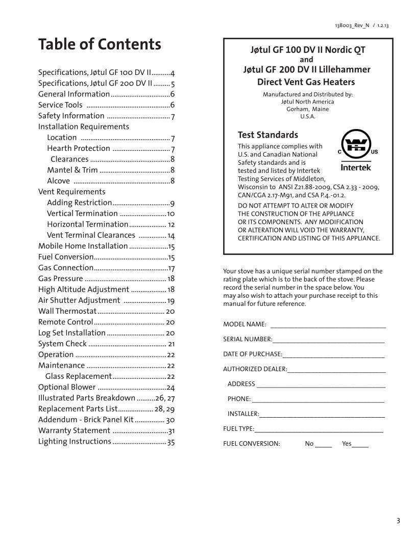
Table of Contents Specifications, Jøtul GF 100 DV II ..........4Specifications, Jøtul GF 200 DV II ......... 5General Information ................................6Service Tools .............................................6Safety Information .................................. 7 Installation Requirements Location ................................................ 7 Hearth Protection ............................... 7 Clearances ...........................................8Mantel&Trim ......................................8 Alcove ....................................................8Vent Requirements Adding Restriction ...............................9 Vertical Termination ......................... 10 Horizontal Termination .................... 12 Vent Terminal Clearances ............... 14MobileHomeInstallation .....................15Fuel Conversion ........................................15 Gas Connection ........................................17Gas Pressure ............................................ 18HighAltitudeAdjustment ................... 18AirShutterAdjustment ....................... 19WallThermostat .................................... 20Remote Control ...................................... 20Log Set Installation ............................... 20System Check .......................................... 21Operation .................................................22Maintenance ...........................................22 Glass Replacement .............................22Optional Blower .....................................24Illustrated Parts Breakdown ..........26,27Replacement Parts List ................... 28, 29Addendum - Brick Panel Kit ................ 30 WarrantyStatement ..............................31Lighting Instructions ............................. 35
Direct Vent Gas HeatersManufacturedandDistributedby:
Jøtul North America Gorham,Maine
U.S.A.
Test StandardsThis appliance complies with U.S. and Canadian National Safety standards and is tested and listed by Intertek TestingServicesofMiddleton,WisconsintoANSIZ21.88-2009,CSA2.33-2009, CAN/CGA2.17-M91,andCSAP.4.-01.2.DONOTATTEMPTTOALTERORMODIFYTHE CONSTRUCTION OF THE APPLIANCE ORITSCOMPONENTS.ANYMODIFICATIONORALTERATIONWILLVOIDTHEWARRANTY,CERTIFICATION AND LISTING OF THIS APPLIANCE.
Jøtul GF 200 DV II Lillehammer andDV II Nordic QT Jøtul GF 100
Yourstovehasauniqueserialnumberstampedontherating plate which is to the back of the stove. Please recordtheserialnumberinthespacebelow.Youmay also wish to attach your purchase receipt to this manual for future reference.
MODELNAME:__________________________________
SERIALNUMBER:_________________________________ DATE OF PURCHASE:______________________________
AUTHORIZEDDEALER:_____________________________ ADDRESS ______________________________________ PHONE: _______________________________________
INSTALLER:_____________________________________ FUELTYPE:______________________________________
FUELCONVERSION:No_____Yes_____
4
138003_Rev_N / 11.2.13
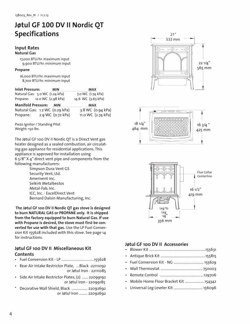
Jøtul GF 100 DV II Nordic QT Specifications
Input RatesNatural Gas 17,000 BTU/hr. maximum input
9,900 BTU/hr. minimum input
Propane 16,000BTU/hr.maximuminput
8,700 BTU/hr. minimum input
Inlet Pressure: MIN MAX NaturalGas:5.0WC(1.24kPa) 7.0WC(1.74kPa)Propane:12.0WC(2.98kPa)14.6WC(3.63kPa)
Manifold Pressure: MIN MAX NaturalGas:1.2WC(0.29kPa) 3.8WC(0.94kPa)Propane:2.9WC(0.72kPa)11.0WC(2.74kPa) Piezo Ignitor / Standing Pilot Weight:150lbs.
Jøtul GF 100 DV II Miscellaneous Kit Contents• FuelConversionKit-LP...................................155628• RearAirIntakeRestrictorPlate, ...Black -22111092
or Jøtul Iron - 22111085 • SideAirIntakeRestrictorPlates,(2) ....... 22099192
or Jøtul Iron - 22099185* DecorativeWallShield,Black ................. 22092692
or Jøtul Iron ......... 22092692
Jøtul GF 100 DV II Accessories• BlowerKit ............................................................155631• AntiqueBrickKit ................................................155815• FuelConversionKit-NG ................................ 155629• WallThermostat ............................................. 750003• RemoteControl ...............................................129706• MobileHomeFloorBracketKit .....................154342• Universal Leg Leveler Kit ............................... 156096
The Jøtul GF 100 DV II Nordic QT is a Direct Vent gas heater designed as a sealed combustion, air circulat-ing gas appliance for residential applications. This appliance is approved for installation using 65/8”X4”directventpipeandcomponentsfromthefollowing manufacturers: Simpson Dura-Vent GS Security Vent, Ltd. Amerivent Inc. SelkirkMetalbestos Metal-Fab,Inc. ICC, Inc. - ExcelDirect Vent BernardDalsinManufacturing,Inc. The Jøtul GF 100 DV II Nordic QT gas stove is designed to burn NATURAL GAS or PROPANE only. It is shipped from the factory equipped to burn Natural Gas. If use withPropaneisdesired,thestovemustfirstbecon-vertedforusewiththatgas. Use the LP Fuel Conver-sionKit155628includedwiththisstove.Seepage14for instructions.
181/4”464mm
163/4”425mm
161/2” 419mm
Flue Collar Centerline
14” 356mm
21”533 mm
221/4”565mm
Leg To Leg
5
138003_Rev_N / 1.2.13
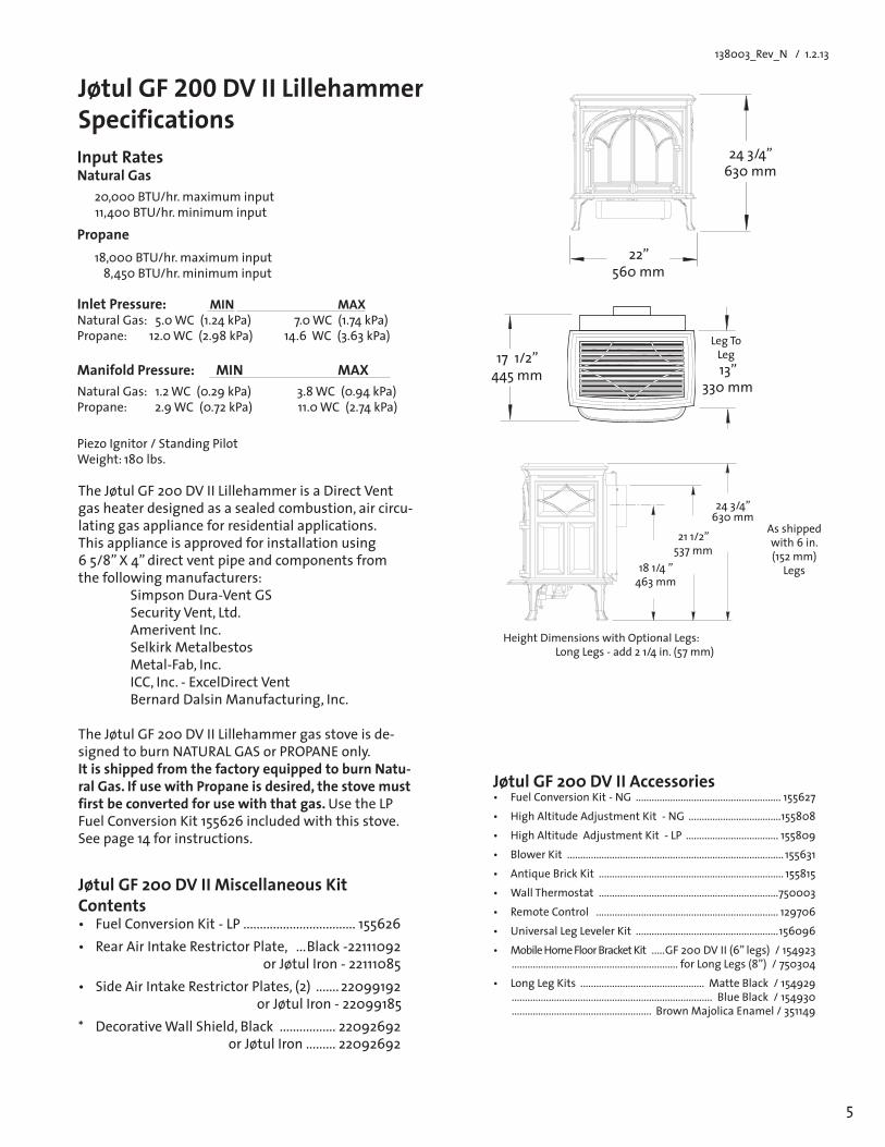
Jøtul GF 200 DV II Lillehammer Specifications
Jøtul GF 200 DV II Accessories• FuelConversionKit-NG ....................................................... 155627• HighAltitudeAdjustmentKit-NG ...................................155808• HighAltitudeAdjustmentKit-LP ................................... 155809• BlowerKit .................................................................................. 155631• AntiqueBrickKit ...................................................................... 155815• WallThermostat ....................................................................750003• RemoteControl ..................................................................... 129706• UniversalLegLevelerKit ......................................................156096• MobileHomeFloorBracketKit .....GF200DVII(6”legs)/154923
............................................................... forLongLegs(8”)/750304• LongLegKits ............................................... MatteBlack/154929
............................................................................ BlueBlack/154930 ..................................................... BrownMajolicaEnamel/351149
Input RatesNatural Gas 20,000 BTU/hr. maximum input
11,400BTU/hr.minimuminput
Propane 18,000 BTU/hr. maximum input
8,450BTU/hr.minimuminput
Inlet Pressure: MIN MAX NaturalGas:5.0WC(1.24kPa) 7.0WC(1.74kPa)Propane:12.0WC(2.98kPa)14.6WC(3.63kPa)
Manifold Pressure: MIN MAX NaturalGas:1.2WC(0.29kPa) 3.8WC(0.94kPa)Propane:2.9WC(0.72kPa)11.0WC(2.74kPa)
Piezo Ignitor / Standing Pilot Weight:180lbs.
The Jøtul GF 200 DV II Lillehammer is a Direct Vent gas heater designed as a sealed combustion, air circu-lating gas appliance for residential applications. This appliance is approved for installation using 65/8”X4”directventpipeandcomponentsfrom the following manufacturers: Simpson Dura-Vent GS Security Vent, Ltd. Amerivent Inc. SelkirkMetalbestos Metal-Fab,Inc. ICC, Inc. - ExcelDirect Vent BernardDalsinManufacturing,Inc. The Jøtul GF 200 DV II Lillehammer gas stove is de-signed to burn NATURAL GAS or PROPANE only. It is shipped from the factory equipped to burn Natu-ralGas.IfusewithPropaneisdesired,thestovemustfirstbeconvertedforusewiththatgas.Use the LP FuelConversionKit155626includedwiththisstove.Seepage14forinstructions.
Jøtul GF 200 DV II Miscellaneous Kit Contents• FuelConversionKit-LP.................................. 155626• RearAirIntakeRestrictorPlate, ...Black -22111092
or Jøtul Iron - 22111085 • SideAirIntakeRestrictorPlates,(2) ....... 22099192
or Jøtul Iron - 22099185* DecorativeWallShield,Black ................. 22092692
or Jøtul Iron ......... 22092692
Height Dimensions with Optional Legs: LongLegs-add21/4in.(57mm)
13”330 mm
Leg To Leg171/2”
445mm
181/4”463mm
211/2”537 mm
As shipped with6in.(152 mm)
Legs
243/4”630mm
243/4”630mm
22”560mm
6
138003_Rev_N / 11.2.13
General InformationIMPORTANT: SAVE THESE INSTRUCTIONS.
1. The installation and repair of this appliance must be done by a qualified service person. Failure to prop-erly install and maintain this heater could result in an unsafe or hazardous installation, which may result in a fire, explosion, property damage, personal injuryorlossoflife.
2. This appliance should be inspected before use and atleastannually.Morefrequentcleaningmaybere-quired due to excessive lint from carpeting, bedding material, etc. It is imperative that control compart-ments, burners and circulating air passageways of the appliance be kept clean.
`S’assurer que le bruleur et le compartiment des com-mandes sont propres. Voir les instructions d’installation et d’utilisation qui accompagnent l’appareil.
3. This appliance may be installed in an aftermarket permanently located, manufactured (mobile) home, where not prohibited by local codes. This appliance is only for use with the type(s) of gas indicated on the rating plate. This appliance is not convertible for use with other gases, unless a certi-fied kit is used.
Cetappareil peut être installé dans un maison pré-fabriquée(mobile)déjàinstalléeàdemeuresilesrèglements locaux le permettent.
Cet appareil doit être utilisé uniquement avec les types de gas indiqués sur la plaque signalétique. Ne pas l’utiliser avec d’autres gas sauf si un kitde conversion certifié est installé.
4. Theinstallationmustconformtolocalcodes.Yourlocal Jøtul authorized dealer can assist you in deter-mining what is required in your area for a safe and legal installation. Some areas require a permit to install a gas burning appliance. Always consult your localbuildinginspectororauthorityhavingjurisdic-tion to determine what regulations apply in your area.
In the absence of local codes, the installation re-quirements must comply with the current National codes. In the U.S., these requirements are estab-lishedintheNationalFuelCode,ANSIZ223.1.(NFPA54).InCanada,thecodeshavebeenestablishedinCAN/CGAB149FuelInstallationCode.
Installer l’appareil selon les codes ou reglements locaux, ou, en l’absence de tels reglements, selon les Codesd’installationCAN/CGA-B149.
5. Do not operate this fireplace if any part of it has been under water. Immediately call a qualified service technician to inspect the heater and to replace any part of the control system and any gas control which has been under water.
Ne pas se servir de cet appareil s’il a ete’ plonge dans l’eau, completement ou en partie. Appeler un technicien qualifie pour inspecter l’appareil et rem-placer toute partie du syste’me de controle et toute commande qui ont ete plonges dans l’eau.
Safety InformationDue to the high operating temperatures this appliance
shouldbelocatedoutoftrafficandawayfromfurniture,draperies,etc.Maintainproperclearancetocombustible mantels and fireplace trim.
Childrenandadultsshouldbealertedtothehazardsofhighsurfacetemperaturesandshouldstayawaytoavoid burns or clothing ignition.
Enfants et adultes doivent être avertis des dangers des températuresdesurfaceélevéesetdevraientresteràl’écart pour éviter les brûlures ou l’inflammation des vêtements.
Youngchildrenshouldbesupervisedwhiletheyareinthesameroomastheappliance.Toddlers,youngchildren and others may be susceptible to accidental contactburns.Aphysicalbarrier,suchasachildguard,isrecommendedtobeusedifthereareat-riskindividuals in the house. To restrict access to a fireplace orstove,installanadjustablesafetygatetokeeptoddlers,youngchildrenandotherat-riskindividualsoutoftheroomandawayfromhotsurfaces.
Lesjeunesenfantsdoiventêtresurveilléspendantqu’ils sont dans la même pièce que l’appareil. Les tout-petits,lesjeunesenfantsetd’autrespeuventêtresensibles aux brûlures par contact accidentel. Une bar-rièrephysique,commeungardedel’enfant,estrecom-mandépourêtreutilisésiilyadespersonnesàrisquedanslamaison.Pourrestreindrel’accèsàunecheminéeouunpoêle,installerunebarrièredesécuritéréglablepourgarderlestout-petits,lesjeunesenfantsetautrespersonnesàrisqueàsesortirdelasalleetàl’écartdessurfaces chaudes.
Any safety screen or guard removed for servicing an appliance must be replaced prior to operating the appliance.
Tout écran ou grille de protection pour l’entretien d’un appareil doit être remplacé avant de faire fonctionner l’appareil.
Clothing or other flammable materials should not be placed on or near the fireplace.
Surveillerlesenfants.Garderlesvêtements,lesmeubles,l’essenceouautresliquidesàvapeurinflammables lin de l’appareil.
6. Donotoperatethefireplacewiththeglassfrontremoved, cracked or broken. Replacement of the glass should be done by a licensed or qualified service person. Only remove glass for routine service. Always handle glass carefully.
Pour utilisation avec les portes en verre cerifiers aved l’appareil seulemend ou. Ne pas utiliser avec des portes on verre.
7. Notify your insurance company before proceding with installation of this fireplace.
7
138003_Rev_N / 1.2.13
LocationIn selecting a location for the stove, consider the following points: 1) Heat distribution 2) Vent termination requirements 3) Gas supply line routing 4)Trafficareas,furniture,draperies,etc.
The stove may be located on or near conventional construction materials, however, proper clearance to combustibles must be maintained in order to provide adequate air circulation around the appliance. Also, it is important to provide adequate access around the stove for servicing and proper operation.
The clearance and hearth specifications listed in this manual are the minimum requirements for combustible material. A combustible material is anything that can burn (i.e. sheet rock, wall paper, wood, fabrics etc.). These surfaces are not limited to those that are visible and also include materials that may be located behind non-com-bustibles.
If you are not sure of the combustible nature of a material, consult your local fire officials. Remember, “Fire Resistant”materialsareconsideredcombustible:theyaredifficulttoignite,butwillburn.Also,“fire-rated”sheetrock is considered combustible.
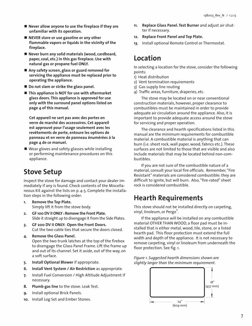
Hearth RequirementsThis stove should not be installed directly on carpeting, vinyl, linoleum, or Pergo®.
If the appliance will be installed on any combustible materialOTHERTHANWOOD,afloorpadmustbein-stalled that is either metal, wood, tile, stone, or a listed hearth pad. This floor protection must extend the full width and depth of the appliance. It is not necessary to remove carpeting, vinyl or linoleum from underneath the floor protection. See fig. 1.
Stove SetupInspect the stove for damage and contact your dealer im-mediatelyifanyisfound.CheckcontentsoftheMiscella-neousKitagainstthelistsonp.4-5.Completetheinstalla-tion steps in the following order: 1. Remove the Top Plate.
Simply lift it from the stove body.2. GF 100 DV II ONLY : Remove the Front Plate.
Slide it straight up to disengage it from the Side Plates.3. GF 200 DV II ONLY: Open the Front Doors.
Cut the two cable ties that secure the doors closed.4. Remove the Glass Panel.
Open the two trunk latches at the top of the firebox to disengage the Glass Panel Frame. Lift the frame up and out of its channel. Set it aside, out of the way, on a soft surface.
5. InstallOptionalBlower if appropriate.6. Install Vent System / Air Restriction as appropriate.7. InstallFuelConversion/HighAltitudeAdjustmentif
necessary.8. Plumb gas line to the stove. Leak Test.9. Install optional Brick Panels.10. Install Log Set and Ember Stones.
Figure 1. Suggested hearth dimensions shown are slightly larger than the minimum requirement.
24” (609mm)
18” (457mm)
Neverallowanyonetousethefireplaceiftheyareunfamiliarwithitsoperation.
NEVER store or use gasoline or any other flammable vapors or liquids in the vicinity of the fireplace.
Neverburnanysolidmaterials(wood,cardboard,paper,coal,etc.)inthisgasfireplace.Usewithnatural gas or propane fuel ONLY.
Anysafetyscreen,glassorguardremovedforservicing the appliance must be replaced prior to operating the appliance.
Do not slam or strike the glass panel.ThisapplianceisNOTforusewithaftermarket
glass doors. This appliance is approved for use onlywiththesurroundpaneloptionslistedonpage 4 of this manual. Cet appareil ne sert pas avec des portes en verre de marché des accessoires. Cet appareil est approuvé pour l’usage seulement avec les revêtementsdeporte,entourelesoptionsdepanneauetenverredepanneauénuméréesàlapage 4 de ce manuel.
Wearglovesandsafetyglasseswhileinstallingor performing maintenance procedures on this appliance.
11. ReplaceGlassPanel.TestBurnerandadjustairshut-ter if necessary.
12. Replace Front Panel and Top Plate.13. Install optional Remote Control or Thermostat.
8
138003_Rev_N / 11.2.13
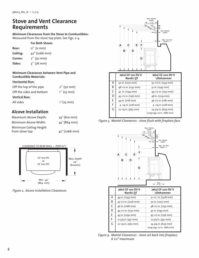
Stove and Vent Clearance RequirementsMinimum Clearances from the Stove to Combustibles: Measuredfromthestovetopplate.Seefigs.2-4. ForBothStovesRear: 0”(0mm)Ceiling: 42”(1066mm)Corner: 2”(50mm)Sides: 3”(76mm)
MinimumClearancesbetweenVentPipeand Combustible Materials:HorizontalRun:Offthetopofthepipe 2”(50mm)Offthesidesandbottom 1”(25mm)Vertical Run: Allsides 1”(25mm)
Figure 3. Mantel Clearances - stove flush with fireplace face.
Figure 4. Mantel Clearances - stove set back into fireplace, 6 1/2” maximum.
Figure 2. Alcove Installation Clearances.
CLEARANCETOREARWALL=ZERO(0”)
GF 100 DVor
GF 200 DV
Max.Depth24”
(610mm)
Alcove InstallationMaximumAlcoveDepth: 24”(610mm)MinimumAlcoveWidth: 34”(864mm)MinimumCeilingHeight fromstovetop: 42”(1066mm)
Min.34” (864mm)
LongLegs:27in.(686mm)
Jøtul GF 100 DV II Jøtul GF 200 DV II Nordic QT LillehammerA 49in.(1245mm) 511/2in.(1308mm)
B 471/2in.(1206mm) 50in.(1270mm)
C 46in.(1168mm) 481/2in.(1232mm)
D 441/2in.(1130mm) 47in.(1194mm)
E 43in.(1092mm) 451/2in.(1156mm)
F 173/4in.(451mm) 173/4in.(451mm)
G 221/4in.(565mm) 243/4in.(629mm)
LongLegs:27in.(686mm)
Jøtul GF 100 DV II Jøtul GF 200 DV II Nordic QT LillehammerA 50 in. (1270 mm) 52 1/2 in. (1333 mm)
B 481/2in.(1232mm) 51in.(1295mm)
C 47in.(1194mm) 491/2in.(1257mm)
D 451/2in.(1156mm) 48in.(1219mm)
E 44in.(1118mm) 461/2in.(1181mm)
F 41/4in.(108mm) 41/4in.(108mm)
G 221/4in.(565mm) 243/4in.(629mm)
�����
��������
����
����������������
����������������
����� ��� �����������
���
� � �
� �
�
�
�����
��������
����
����������������
����������������
����� ��� �����������
���
� � �
� �
�
�
����������
9
138003_Rev_N / 1.2.13
�������
Venting RequirementsBoth stoves may be installed with a vertical or horizon-tal termination and must conform to the configuration requirements described in this section. This appliance is approved for use with vent systems from the following manufacturers: •SimpsonDura-VentGS •AmericanMetalProducts(Amerivent) •SecurityChimneysInternational,Ltd.(SecureVent) •SelkirkMetalbestos(DirectTemp) •Metal-Fab,Inc.(DirectVent •IndustrialChimneyCorp.(ExcelDirectVent) •BernardDalsinMfg.(ProForm) Usepartsofonemanufactureronly-DONOTMIXVENTCOMPONENTSFROMDIFFERENTMANUFACTURERSINTHESAMESYSTEM.
Installation of any components not manufactured or approved by Jøtul or failure to meet all clearance require-ments will void all warranties and could result in property damage,bodilyinjury,orseriousfire.
The approved vent configurations described in this manual are derived from extensive testing under con-trolled laboratory conditions. Gas appliance performance can be negatively affected by variables present in the installation environment, i.e: atmospheric pressure, strong prevailingwinds,adjacentstructuresandtrees,snowaccumulation, etc. These conditions should be taken into consideration by the installer and stove owner when plan-ning the vent system design.
IMPORTANT• JOINT SEALING REQUIREMENT:APPLYA1/8”BEAD
OFHIGH-TEMPERATURESEALANT(SUCHASMIL-PAC®)TOTHEMALESECTIONOFTHEINNER VENT PIPE. THE CEMENTSHOULDFORMASEALBETWEENTHEINNERAND OUTER PIPES.
• NEVERMODIFYANYVENT-INGCOMPONENT,ORUSEANYDAMAGEDVENTINGPRODUCT.
• THEGASAPPLIANCEANDVENTSYSTEMMUSTBEVENTEDDIRECTLYTOTHEOUTSIDE OF THE BUILDING AND NEVER ATTACHED TO ACHIMNEYSERVINGASOLIDFUELORGASBURNINGAPPLIANCE.EACHDIRECTVENTGASAPPLIANCEMUSTHAVEITSOWNSEPARATEVENTSYSTEM.COMMONVENTSYSTEMSAREPROHIBITED.
• IFVENTINGSYSTEMISDISASSEMBLEDFORANYREA-SON, REINSTALL PER THE INSTRUCTIONS PROVIDED FOR THE INITIAL INSTALLATION.
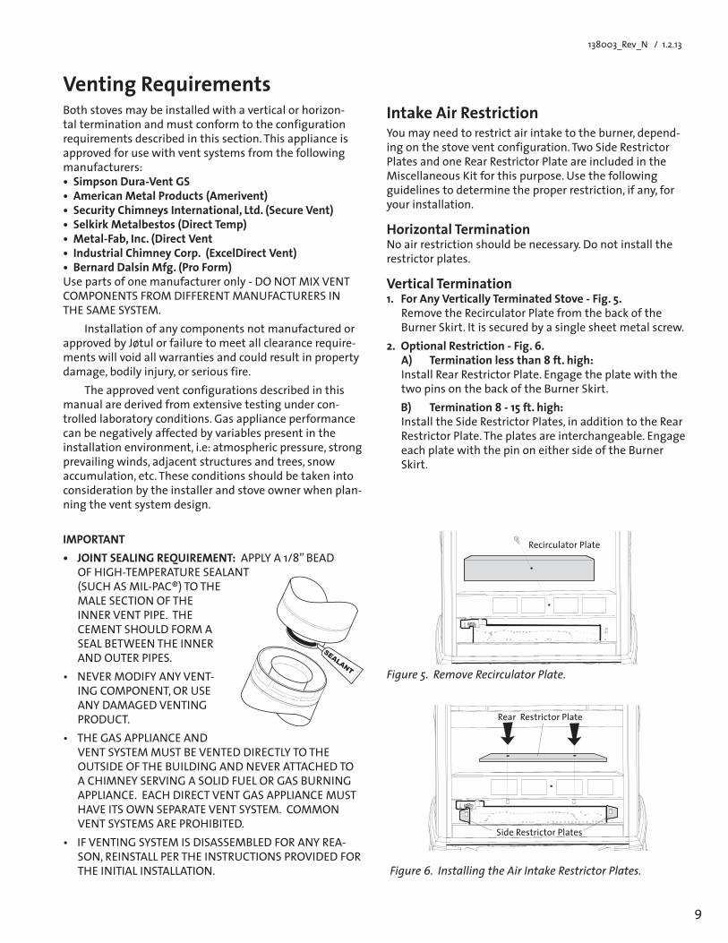
Intake Air RestrictionYoumayneedtorestrictairintaketotheburner,depend-ing on the stove vent configuration. Two Side Restrictor Plates and one Rear Restrictor Plate are included in the MiscellaneousKitforthispurpose.Usethefollowingguidelines to determine the proper restriction, if any, for your installation.
HorizontalTerminationNo air restriction should be necessary. Do not install the restrictor plates.
Vertical Termination1. For Any Vertically Terminated Stove - Fig. 5.
Remove the Recirculator Plate from the back of the Burner Skirt. It is secured by a single sheet metal screw.
2. Optional Restriction - Fig. 6. A) Termination less than 8 ft. high:Install Rear Restrictor Plate. Engage the plate with the two pins on the back of the Burner Skirt.
B) Termination8-15ft.high:Install the Side Restrictor Plates, in addition to the Rear Restrictor Plate. The plates are interchangeable. Engage each plate with the pin on either side of the Burner Skirt.
Figure 6. Installing the Air Intake Restrictor Plates.
Figure 5. Remove Recirculator Plate.
Recirculator Plate
Rear Restrictor Plate
Side Restrictor Plates
10
138003_Rev_N / 11.2.13
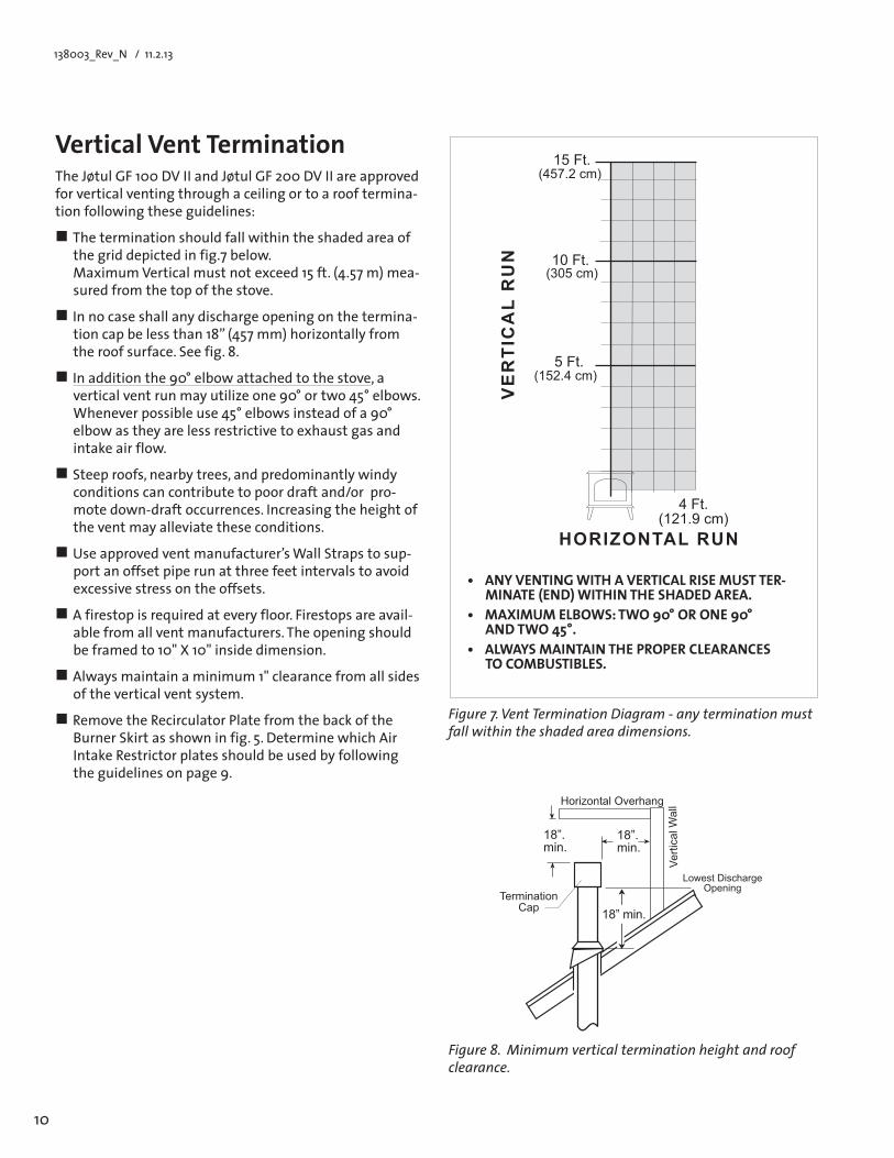
Vertical Vent TerminationThe Jøtul GF 100 DV II and Jøtul GF 200 DV II are approved for vertical venting through a ceiling or to a roof termina-tion following these guidelines:
The termination should fall within the shaded area of the grid depicted in fig.7 below. MaximumVerticalmustnotexceed15ft.(4.57m)mea-sured from the top of the stove.
In no case shall any discharge opening on the termina-tioncapbelessthan18”(457mm)horizontallyfromthe roof surface. See fig. 8.
In addition the 90° elbow attached to the stove, a verticalventrunmayutilizeone90°ortwo45°elbows.Wheneverpossibleuse45°elbowsinsteadofa90°elbow as they are less restrictive to exhaust gas and intake air flow.
Steep roofs, nearby trees, and predominantly windy conditions can contribute to poor draft and/or pro-mote down-draft occurrences. Increasing the height of the vent may alleviate these conditions.
Useapprovedventmanufacturer’sWallStrapstosup-port an offset pipe run at three feet intervals to avoid excessive stress on the offsets.
A firestop is required at every floor. Firestops are avail-able from all vent manufacturers. The opening should beframedto10"X10"insidedimension.
Always maintain a minimum 1" clearance from all sides of the vertical vent system.
Remove the Recirculator Plate from the back of the Burner Skirt as shown in fig. 5. Determine which Air Intake Restrictor plates should be used by following the guidelines on page 9.
• ANY VENTING WITH A VERTICAL RISE MUST TER-MINATE (END) WITHIN THE SHADED AREA.
• MAXIMUMELBOWS:TWO90°ORONE90° ANDTWO45°.
• ALWAYSMAINTAINTHEPROPERCLEARANCES TOCOMBUSTIBLES.
Figure 7. Vent Termination Diagram - any termination must fall within the shaded area dimensions.
�������������������
���
�������
���
������������
�������
����������������������
�������
�������
Figure 8. Minimum vertical termination height and roof clearance.
����������������
���������������
��������������
���������������
���
���
����
��
��������������
11
138003_Rev_N / 1.2.13
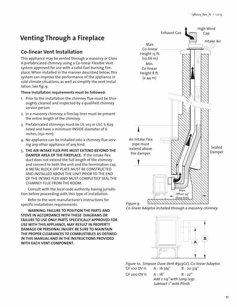
Co-linear Vent InstallationThis appliance may be vented through a masonry or Class A prefabricated chimney using a Co-linear Flexible Vent system approved for use with a solid-fuel burning fire-place.Wheninstalledinthemannerdescribedbelow,thissystem can improve the performance of the appliance in cold climate situations, as well as simplify the vent instal-lation. See fig. 9. Theseinstallationrequirementsmustbefollowed:1. Prior to the installation the chimney flue must be thor-
oughly cleaned and inspected by a qualified chimney service person.
2. In a masonry chimney, a fireclay liner must be present the entire length of the chimney.
3. PrefabricatedchimneysmustbeUL103orULCS-629listedandhaveaminimumINSIDEdiameterof6inches, (150 mm).
4. Noappliancecanbeinstalledintoachimneyflueserv-ing any other appliance of any kind.
5. THEAIRINTAKEFLEXPIPEMUSTEXTENDBEYONDTHEDAMPER AREA OF THE FIREPLACE. If the intake flex duct does not extend the full length of the chimney and connect to both the unit and the termination cap, AMETALBLOCKOFFPLATEMUSTBECONSTRUCTEDAND INSTALLED ABOVE THE UNIT PRIOR TO THE END OFTHEINTAKEFLEXANDMUSTCOMPLETELYSEALTHECHIMNEYFLUEFROMTHEROOM.Consultwiththelocalcodeauthorityhavingjurisdic-
tion before proceeding with this type of installation.Refer to the vent manufacturer’s instructions for
specific installation requirements.WARNING: FAILURE TO POSITION THE PARTS AND
STOVE IN ACCORDANCE WITH THESE DIAGRAMS OR FAILURE TO USE ONLY PARTS SPECIFICALLY APPROVED FOR USEWITHTHISAPPLIANCE,MAYRESULTINPROPERTYDAMAGEORPERSONALINJURY.BESURETOMAINTAINTHEPROPERCLEARANCESTOCOMBUSTIBLESASDEFINEDIN THIS MANUAL AND IN THE INSTRUCTIONS PROVIDED WITH EACH VENT COMPONENT.
Figure 9. Co-linear Adaptor installed through a masonry chimney.
Figure 10. Simpson Dura-Vent #923GCL Co-linear Adaptor. GF100DVII: A:163/4” B:203/4”GF200DVII: A:18” B:22” Add 2 1/4” with Long Legs. Subtract 1” with Plinth
Venting Through a Fireplace Intake Air
Exhaust GasHighWind
Cap
Max. Co-linear
Height 15 ft. (10.66m)Min.
Co-linear Height 8 ft. (2.44m)
Air Intake Flex pipe must
extend above the damper.
Sealed Damper
Max.Offset24”(609mm)
��
12
138003_Rev_N / 11.2.13
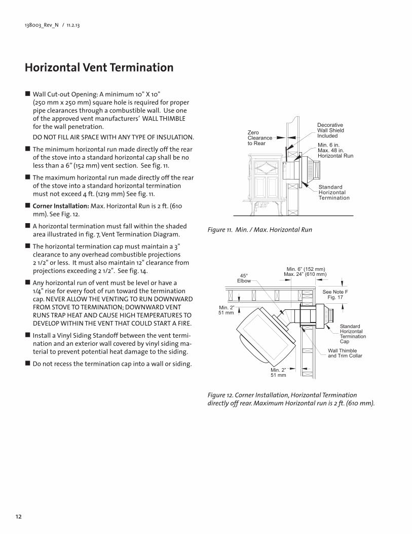
Figure 12. Corner Installation, Horizontal Termination directly off rear. Maximum Horizontal run is 2 ft. (610 mm).
HorizontalVentTermination
WallCut-outOpening:Aminimum10"X10"(250 mm x 250 mm) square hole is required for proper pipe clearances through a combustible wall. Use one oftheapprovedventmanufacturers’WALLTHIMBLEfor the wall penetration.
DONOTFILLAIRSPACEWITHANYTYPEOFINSULATION.
The minimum horizontal run made directly off the rear of the stove into a standard horizontal cap shall be no lessthana6”(152mm)ventsection.See fig. 11.
The maximum horizontal run made directly off the rear of the stove into a standard horizontal termination mustnotexceed4ft.(1219mm)Seefig.11.
Corner Installation:Max.HorizontalRunis2ft.(610mm). See Fig. 12.
A horizontal termination must fall within the shaded area illustrated in fig. 7, Vent Termination Diagram.
The horizontal termination cap must maintain a 3" clearancetoanyoverheadcombustibleprojections 2 1/2" or less. It must also maintain 12" clearance from projectionsexceeding21/2".Seefig.14.
Any horizontal run of vent must be level or have a 1/4"riseforeveryfootofruntowardtheterminationcap.NEVERALLOWTHEVENTINGTORUNDOWNWARDFROMSTOVETOTERMINATION;DOWNWARDVENTRUNSTRAPHEATANDCAUSEHIGHTEMPERATURESTODEVELOPWITHINTHEVENTTHATCOULDSTARTAFIRE.
Install a Vinyl Siding Standoff between the vent termi-nation and an exterior wall covered by vinyl siding ma-terial to prevent potential heat damage to the siding.
Do not recess the termination cap into a wall or siding.
Figure 11. Min. / Max. Horizontal Run
�����������������������������������
������������������
��������������������������
�����������������������������
������������
�������������
��������
��������� ��������������� ������
�����������������
���������������������������
������������ ������������������
13
138003_Rev_N / 1.2.13
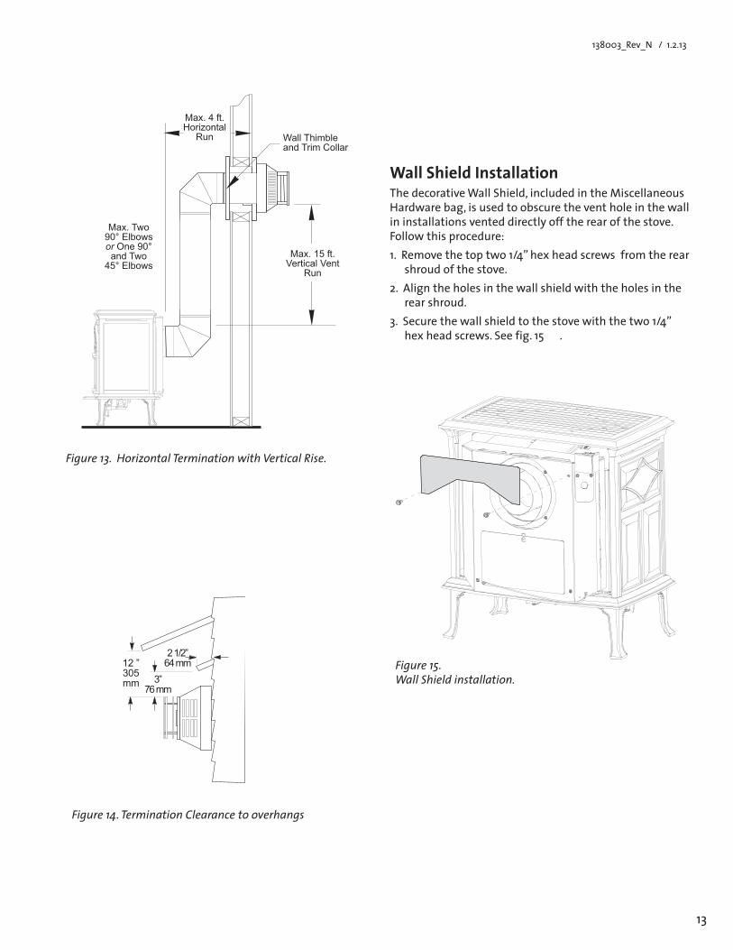
Wall Shield InstallationThedecorativeWallShield,includedintheMiscellaneousHardware bag, is used to obscure the vent hole in the wall in installations vented directly off the rear of the stove. Follow this procedure:1.Removethetoptwo1/4”hexheadscrewsfromtherear
shroud of the stove.2. Align the holes in the wall shield with the holes in the
rear shroud. 3.Securethewallshieldtothestovewiththetwo1/4”
hex head screws. See fig. 15 .
Figure 14. Termination Clearance to overhangs
Figure 15. Wall Shield installation.��
�����
���������
�����������
Figure 13. Horizontal Termination with Vertical Rise.
���������������������������
����� ������������
���
�����������������������������������
��������������������
����������������
14
138003_Rev_N / 11.2.13
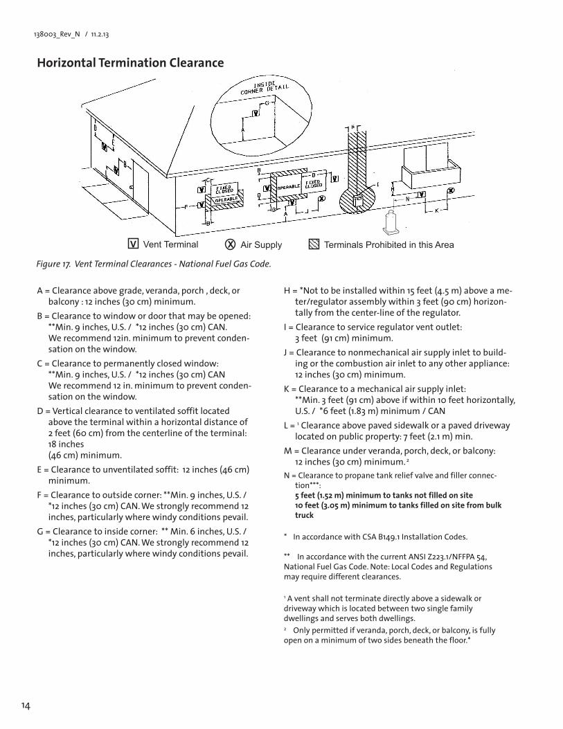
Figure 17. Vent Terminal Clearances - National Fuel Gas Code.
HorizontalTerminationClearance
A=Clearanceabovegrade,veranda,porch,deck,orbalcony : 12 inches (30 cm) minimum.
B=Clearancetowindowordoorthatmaybeopened:**Min.9inches,U.S./*12inches(30cm)CAN. Werecommend12in.minimumtopreventconden-sation on the window.
C=Clearancetopermanentlyclosedwindow: **Min.9inches,U.S./*12inches(30cm)CAN Werecommend12in.minimumtopreventconden-sation on the window.
D=Verticalclearancetoventilatedsoffitlocatedabove the terminal within a horizontal distance of 2feet(60cm)fromthecenterlineoftheterminal:18 inches (46cm)minimum.
E=Clearancetounventilatedsoffit:12inches(46cm)minimum.
F=Clearancetooutsidecorner:**Min.9inches,U.S./*12inches(30cm)CAN.Westronglyrecommend12inches, particularly where windy conditions pevail.
G=Clearancetoinsidecorner:**Min.6inches,U.S./*12inches(30cm)CAN.Westronglyrecommend12inches, particularly where windy conditions pevail.
* InaccordancewithCSAB149.1InstallationCodes. **InaccordancewiththecurrentANSIZ223.1/NFFPA54,National Fuel Gas Code. Note: Local Codes and Regulations may require different clearances.
1 A vent shall not terminate directly above a sidewalk or driveway which is located between two single family dwellings and serves both dwellings.2 Only permitted if veranda, porch, deck, or balcony, is fully open on a minimum of two sides beneath the floor.*
H=*Nottobeinstalledwithin15feet(4.5m)aboveame-ter/regulator assembly within 3 feet (90 cm) horizon-tally from the center-line of the regulator.
I=Clearancetoserviceregulatorventoutlet: 3 feet (91 cm) minimum.
J=Clearancetononmechanicalairsupplyinlettobuild-ing or the combustion air inlet to any other appliance: 12 inches (30 cm) minimum.
K=Clearancetoamechanicalairsupplyinlet: **Min.3feet(91cm)aboveifwithin10feethorizontally,U.S./*6feet(1.83m)minimum/CAN
L=1 Clearance above paved sidewalk or a paved driveway located on public property: 7 feet (2.1 m) min.
M=Clearanceunderveranda,porch,deck,orbalcony: 12 inches (30 cm) minimum. 2
N=Clearancetopropanetankreliefvalveandfillerconnec-tion***: 5 feet (1.52 m) minimum to tanks not filled on site 10 feet (3.05 m) minimum to tanks filled on site from bulk truck
�
������������� ���������� ������������ �������������������� �
15
138003_Rev_N / 1.2.13
Tools required:• 1/2”openendedwrenchordeep-wellsocket,TorxT20
orslottedscrewdriver,4mmallenwrench.
Conversion Kit Contents:• 1,regulatortowerlabeledforpropane• 3,regulatortowerscrews• 1, burner orifice (GF100:#48forNG,#56forLP)
(GF200:#46forNG,1.20mmforLP)• 1,pilotorifice(#51forNG,#30forLP)• LabelA-tobecompletedandappliedto
the back of the stove• LabelB-applytothestove’sRatingPlate• Smallvalvelabel-applytovalvebody Conversion instructions are also shipped in the stove
with the conversion kit.
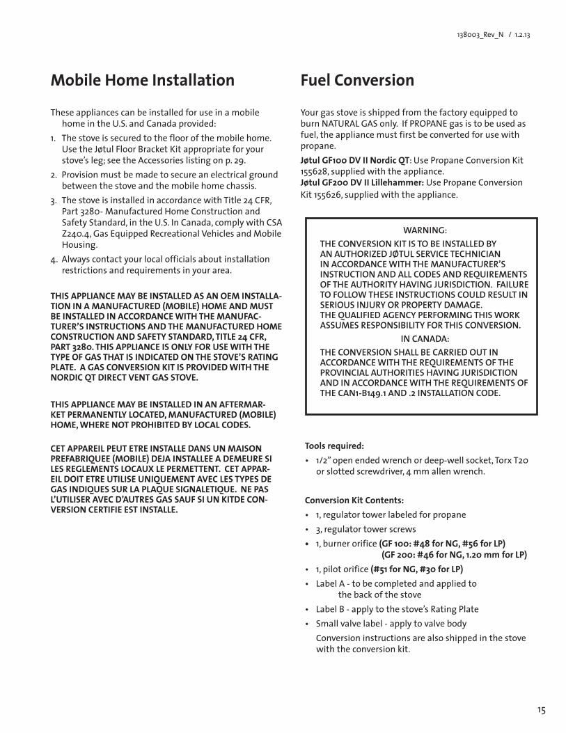
Mobile Home Installation
These appliances can be installed for use in a mobile home in the U.S. and Canada provided:
1. The stove is secured to the floor of the mobile home. Use the Jøtul Floor Bracket Kit appropriate for your stove’s leg; see the Accessories listing on p. 29.
2. Provision must be made to secure an electrical ground between the stove and the mobile home chassis.
3. ThestoveisinstalledinaccordancewithTitle24CFR,Part3280-ManufacturedHomeConstructionandSafety Standard, in the U.S. In Canada, comply with CSA Z240.4,GasEquippedRecreationalVehiclesandMobileHousing.
4. Alwayscontactyourlocalofficialsaboutinstallationrestrictions and requirements in your area.
THISAPPLIANCEMAYBEINSTALLEDASANOEMINSTALLA-TIONINAMANUFACTURED(MOBILE)HOMEANDMUSTBEINSTALLEDINACCORDANCEWITHTHEMANUFAC-TURER’S INSTRUCTIONS AND THE MANUFACTURED HOME CONSTRUCTIONANDSAFETYSTANDARD,TITLE24CFR,PART 3280. THIS APPLIANCE IS ONLY FOR USE WITH THE TYPE OF GAS THAT IS INDICATED ON THE STOVE’S RATING PLATE. A GAS CONVERSION KIT IS PROVIDED WITH THE NORDIC QT DIRECT VENT GAS STOVE.
THISAPPLIANCEMAYBEINSTALLEDINANAFTERMAR-KETPERMANENTLYLOCATED,MANUFACTURED(MOBILE)HOME,WHERENOTPROHIBITEDBYLOCALCODES.
CET APPAREIL PEUT ETRE INSTALLE DANS UN MAISON PREFABRIQUEE(MOBILE)DEJAINSTALLEEADEMEURESILES REGLEMENTS LOCAUX LE PERMETTENT. CET APPAR-EIL DOIT ETRE UTILISE UNIQUEMENT AVEC LES TYPES DE GAS INDIQUES SUR LA PLAQUE SIGNALETIQUE. NE PAS L’UTILISER AVEC D’AUTRES GAS SAUF SI UN KITDE CON-VERSION CERTIFIE EST INSTALLE.
Fuel Conversion
Yourgasstoveisshippedfromthefactoryequippedtoburn NATURAL GAS only. If PROPANE gas is to be used as fuel, the appliance must first be converted for use with propane.Jøtul GF100 DV II Nordic QT: Use Propane Conversion Kit 155628,suppliedwiththeappliance. Jøtul GF200 DV II Lillehammer: Use Propane Conversion Kit155626,suppliedwiththeappliance.
WARNING:THE CONVERSION KIT IS TO BE INSTALLED BY AN AUTHORIZED JØTUL SERVICE TECHNICIAN IN ACCORDANCE WITH THE MANUFACTURER’S INSTRUCTION AND ALL CODES AND REQUIREMENTS OF THE AUTHORITY HAVING JURISDICTION. FAILURE TO FOLLOW THESE INSTRUCTIONS COULD RESULT IN SERIOUS INJURY OR PROPERTY DAMAGE. THE QUALIFIED AGENCY PERFORMING THIS WORK ASSUMES RESPONSIBILITY FOR THIS CONVERSION.
IN CANADA:THE CONVERSION SHALL BE CARRIED OUT IN ACCORDANCE WITH THE REQUIREMENTS OF THE PROVINCIAL AUTHORITIES HAVING JURISDICTION AND IN ACCORDANCE WITH THE REQUIREMENTS OF THE CAN1-B149.1 AND .2 INSTALLATION CODE.
16
138003_Rev_N / 11.2.13
Gas Conversion Procedure 1. Turn off gas supply to stove.2. Remove the stove Top Plate (3).3. GF 100 DV II Only: Remove the front plate from the
stove. Pull the casting straight up and out away from the side panels. Pull the panel upward with one hand while the other pushes against the top of the firebox.
4. Releasethetrunklatchesatthetopofthefirebox.Care-fully lift the glass frame up and out.
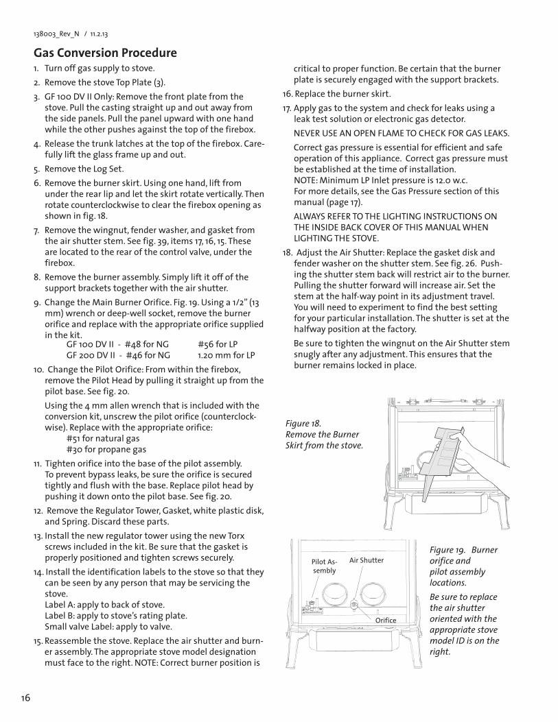
5. Remove the Log Set.6. Removetheburnerskirt.Usingonehand,liftfrom
under the rear lip and let the skirt rotate vertically. Then rotate counterclockwise to clear the firebox opening as shown in fig. 18.
7. Remove the wingnut, fender washer, and gasket from theairshutterstem.Seefig.39,items17,16,15.Theseare located to the rear of the control valve, under the firebox.
8. Remove the burner assembly. Simply lift it off of the support brackets together with the air shutter.
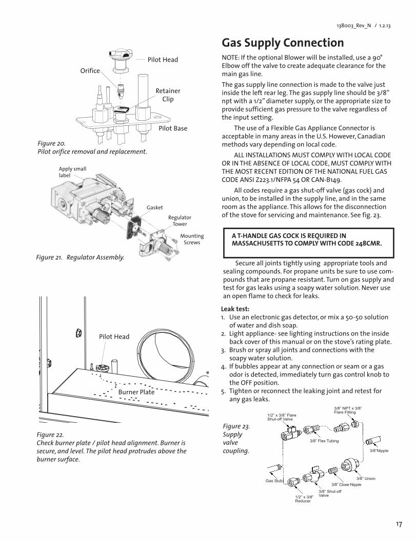
9.ChangetheMainBurnerOrifice.Fig.19.Usinga1/2”(13mm) wrench or deep-well socket, remove the burner orifice and replace with the appropriate orifice supplied in the kit. GF100DVII-#48forNG #56forLP GF200DVII-#46forNG 1.20mmforLP
10. Change the Pilot Orifice: From within the firebox, remove the Pilot Head by pulling it straight up from the pilot base. See fig. 20.
Usingthe4mmallenwrenchthatisincludedwiththeconversion kit, unscrew the pilot orifice (counterclock-wise). Replace with the appropriate orifice: #51 for natural gas #30 for propane gas
11. Tighten orifice into the base of the pilot assembly. To prevent bypass leaks, be sure the orifice is secured tightly and flush with the base. Replace pilot head by pushing it down onto the pilot base. See fig. 20.
12. Remove the Regulator Tower, Gasket, white plastic disk, and Spring. Discard these parts.
13. Install the new regulator tower using the new Torx screws included in the kit. Be sure that the gasket is properly positioned and tighten screws securely.
14.Installtheidentificationlabelstothestovesothattheycan be seen by any person that may be servicing the stove. Label A: apply to back of stove. Label B: apply to stove’s rating plate. Small valve Label: apply to valve.
15. Reassemble the stove. Replace the air shutter and burn-er assembly. The appropriate stove model designation must face to the right. NOTE: Correct burner position is
critical to proper function. Be certain that the burner plate is securely engaged with the support brackets.
16.Replacetheburnerskirt.17. Apply gas to the system and check for leaks using a
leak test solution or electronic gas detector. NEVERUSEANOPENFLAMETOCHECKFORGASLEAKS. Correct gas pressure is essential for efficient and safe
operation of this appliance. Correct gas pressure must be established at the time of installation. NOTE:MinimumLPInletpressureis12.0w.c. For more details, see the Gas Pressure section of this manual (page 17).
ALWAYSREFERTOTHELIGHTINGINSTRUCTIONSONTHEINSIDEBACKCOVEROFTHISMANUALWHENLIGHTING THE STOVE.
18.AdjusttheAirShutter:Replacethegasketdiskandfenderwasherontheshutterstem.Seefig.26.Push-ing the shutter stem back will restrict air to the burner. Pulling the shutter forward will increase air. Set the stematthehalf-waypointinitsadjustmenttravel.Youwillneedtoexperimenttofindthebestsettingfor your particular installation. The shutter is set at the halfway position at the factory.
Be sure to tighten the wingnut on the Air Shutter stem snuglyafteranyadjustment.Thisensuresthattheburner remains locked in place.
Figure 18. Remove the Burner Skirt from the stove.
Figure 19. Burner orifice and pilot assembly locations.Be sure to replace the air shutter oriented with the appropriate stove model ID is on the right.
Orifice
Air ShutterPilot As-sembly
17
138003_Rev_N / 1.2.13
Regulator Tower
Gasket
Apply small label
MountingScrews
Gas Supply ConnectionNOTE: If the optional Blower will be installed, use a 90° Elbow off the valve to create adequate clearance for the main gas line. Thegassupplylineconnectionismadetothevalvejustinsidetheleftrearleg.Thegassupplylineshouldbe3/8”nptwitha1/2”diametersupply,ortheappropriatesizetoprovide sufficient gas pressure to the valve regardless of the input setting.
The use of a Flexible Gas Appliance Connector is acceptable in many areas in the U.S. However, Canadian methods vary depending on local code.
ALLINSTALLATIONSMUSTCOMPLYWITHLOCALCODEORINTHEABSENCEOFLOCALCODE,MUSTCOMPLYWITHTHEMOSTRECENTEDITIONOFTHENATIONALFUELGASCODEANSIZ223.1/NFPA54ORCAN-B149.
All codes require a gas shut-off valve (gas cock) and union, to be installed in the supply line, and in the same room as the appliance. This allows for the disconnection of the stove for servicing and maintenance. See fig. 23.
Figure 23. Supply valve coupling.
Leak test:1. Use an electronic gas detector, or mix a 50-50 solution
of water and dish soap.2. Light appliance- see lighting instructions on the inside
back cover of this manual or on the stove’s rating plate.3. Brushorsprayalljointsandconnectionswiththe
soapy water solution.4. Ifbubblesappearatanyconnectionorseamoragas
odor is detected, immediately turn gas control knob to the OFF position.
5. Tightenorreconnecttheleakingjointandretestforany gas leaks.
���������������������� �������
���������������
���������������������������
����������
��������
������������������
���������� ������
������� ���������
�������� �
Orifice
Pilot Base
Pilot Head
Figure 20. Pilot orifice removal and replacement.
A T-HANDLE GAS COCK IS REQUIRED IN MASSACHUSETTS TO COMPLY WITH CODE 248CMR.
Securealljointstightlyusingappropriatetoolsandsealing compounds. For propane units be sure to use com-pounds that are propane resistant. Turn on gas supply and test for gas leaks using a soapy water solution. Never use an open flame to check for leaks.
Figure 22. Check burner plate / pilot head alignment. Burner is secure, and level. The pilot head protrudes above the burner surface.
Figure 21. Regulator Assembly.
Retainer Clip
Pilot Head
Burner Plate
18
138003_Rev_N / 11.2.13
Gas PressureCorrect gas pressure is essential for efficient and safe op-eration. It is important that the correct pressure is estab-lished at the time of the installation. Proper gas pressure provides a consistent flow of gas to the appliance and is instrumental in checking for gas leaks.
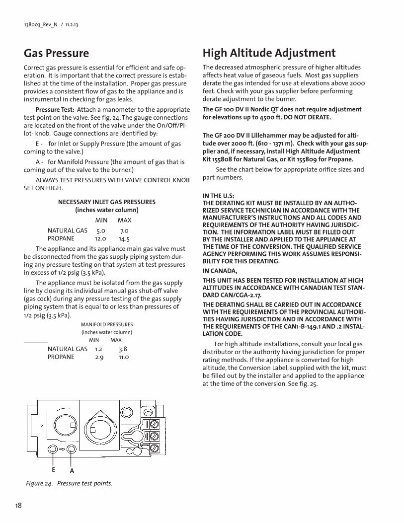
Pressure Test: Attach a manometer to the appropriate testpointonthevalve.Seefig.24.Thegaugeconnectionsare located on the front of the valve under the On/Off/Pi-lot- knob. Gauge connections are identified by:
E - for Inlet or Supply Pressure (the amount of gas coming to the valve.)
A-forManifoldPressure(theamountofgasthatiscoming out of the valve to the burner.)
ALWAYSTESTPRESSURESWITHVALVECONTROLKNOBSET ON HIGH.
HighAltitudeAdjustmentThe decreased atmospheric pressure of higher altitudes affectsheatvalueofgaseousfuels.Mostgassuppliersderate the gas intended for use at elevations above 2000 feet. Check with your gas supplier before performing derateadjustmenttotheburner.TheGF100DVIINordicQTdoesnotrequireadjustmentfor elevations up to 4500 ft. DO NOT DERATE. TheGF200DVIILillehammermaybeadjustedforalti-tudeover2000ft.(610-1371m).Checkwithyourgassup-plierand,ifnecessary,installHighAltitudeAdjustmentKit155808forNaturalGas,orKit155809forPropane.
See the chart below for appropriate orifice sizes and part numbers.
IN THE U.S: THEDERATINGKITMUSTBEINSTALLEDBYANAUTHO-RIZED SERVICE TECHNICIAN IN ACCORDANCE WITH THE MANUFACTURER’S INSTRUCTIONS AND ALL CODES AND REQUIREMENTS OF THE AUTHORITY HAVING JURISDIC-TION.THEINFORMATIONLABELMUSTBEFILLEDOUTBYTHEINSTALLERANDAPPLIEDTOTHEAPPLIANCEATTHE TIME OF THE CONVERSION. THE QUALIFIED SERVICE AGENCY PERFORMING THIS WORK ASSUMES RESPONSI-BILITYFORTHISDERATING.INCANADA,THISUNITHASBEENTESTEDFORINSTALLATIONATHIGHALTITUDES IN ACCORDANCE WITH CANADIAN TEST STAN-DARD CAN/CGA-2.17.THEDERATINGSHALLBECARRIEDOUTINACCORDANCEWITH THE REQUIREMENTS OF THE PROVINCIAL AUTHORI-TIES HAVING JURISDICTION AND IN ACCORDANCE WITH THEREQUIREMENTSOFTHECAN1-B-149.1AND.2INSTAL-LATION CODE.
For high altitude installations, consult your local gas distributorortheauthorityhavingjurisdictionforproperrating methods. If the appliance is converted for high altitude, the Conversion Label, supplied with the kit, must be filled out by the installer and applied to the appliance at the time of the conversion. See fig. 25.
NECESSARY INLET GAS PRESSURES (incheswatercolumn)
MINMAX NATURAL GAS 5.0 7.0 PROPANE 12.0 14.5
The appliance and its appliance main gas valve must be disconnected from the gas supply piping system dur-ing any pressure testing on that system at test pressures in excess of 1/2 psig (3.5 kPa).
The appliance must be isolated from the gas supply line by closing its individual manual gas shut-off valve (gas cock) during any pressure testing of the gas supply piping system that is equal to or less than pressures of 1/2 psig (3.5 kPa).
MANIFOLDPRESSURES(inches water column)
MINMAX
NATURAL GAS 1.2 3.8 PROPANE 2.9 11.0
E A
Figure 24. Pressure test points.
19
138003_Rev_N / 1.2.13
Flame Appearance - AirShutterAdjustmentWARNING: AIR SHUTTER ADJUSTMENTS SHOULD ONLY BEPERFORMEDBYAQUALIFIEDPROFESSIONALSERVICETECHNICIAN.Theairshuttersettingattheburnerorificecanbeadjust-ed to achieve the desired flame appearance. The shutter is set in the mid-range at the factory, however, you will want toadjustitifafuelconversionkithasbeeninstalledoriftheflamepatternisnotasdesired.Theadjustmentstemislocated under the firebox, directly behind the gas control valve. Generally, flame appearance is a matter of prefer-ence,howevermostpeopleenjoyawarmyellowishflame.
Too much air - the appliance will generate a flame that isblueandtransparent,oran“anemic”flame.
Not enough air - the burner will generate very long yellow flames resulting in soot. Sooting produces black deposits on the logs, on the inside walls of the appliance, and potentially on the exterior termination cap.
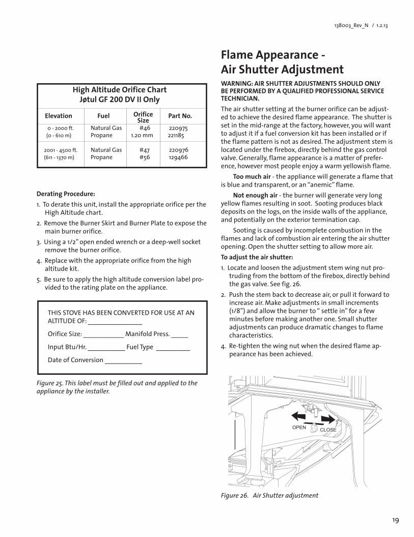
Sooting is caused by incomplete combustion in the flames and lack of combustion air entering the air shutter opening. Open the shutter setting to allow more air.Toadjusttheairshutter:1.Locateandloosentheadjustmentstemwingnutpro-
truding from the bottom of the firebox, directly behind thegasvalve.Seefig.26.
2. Push the stem back to decrease air, or pull it forward to increaseair.Makeadjustmentsinsmallincrements (1/8”)andallowtheburnerto“settlein”forafewminutes before making another one. Small shutter adjustmentscanproducedramaticchangestoflamecharacteristics.
4. Re-tightenthewingnutwhenthedesiredflameap-pearance has been achieved.
Figure 26. Air Shutter adjustment
Derating Procedure:1. To derate this unit, install the appropriate orifice per the
High Altitude chart.2. Remove the Burner Skirt and Burner Plate to expose the
main burner orifice.3.Usinga1/2”openendedwrenchoradeep-wellsocket
remove the burner orifice.4.Replacewiththeappropriateorificefromthehigh
altitude kit.5. Be sure to apply the high altitude conversion label pro-
vided to the rating plate on the appliance.
THIS STOVE HAS BEEN CONVERTED FOR USE AT AN ALTITUDE OF: ________________
OrificeSize:____________ManifoldPress._____
Input Btu/Hr. ___________ Fuel Type __________
Date of Conversion ___________
Figure 25. This label must be filled out and applied to the appliance by the installer.
High Altitude Orifice Chart Jøtul GF 200 DV II Only
Elevation Fuel Part No.
0 - 2000 ft. NaturalGas #46 220975(0-610m) Propane 1.20 mm 221185
2001-4500ft. NaturalGas #47 220976(611-1370m) Propane #56 129466
Orifice Size
���� �����
20
138003_Rev_N / 11.2.13
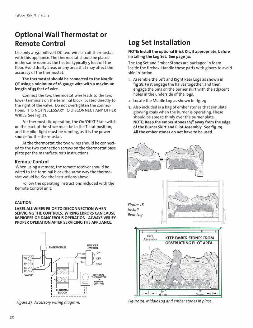
Optional Wall Thermostat or Remote ControlUse only a 750 millivolt DC two-wire circuit thermostat with this appliance. The thermostat should be placed in the same room as the heater, typically 5 feet off the floor. Avoid drafty areas or any area that may affect the accuracy of the thermostat.
The thermostat should be connected to the Nordic QTusingaminimumof16gaugewirewithamaximumlengthof35feetofwire.
Connect the two thermostat wire leads to the two lower terminals on the terminal block located directly to the right of the valve. Do not overtighten the connec-tions. IT IS NOT NECESSARY TO DISCONNECT ANY OTHER WIRES. See Fig. 27.
For thermostatic operation, the On/Off/T-Stat switch on the back of the stove must be in the T-stat position, and the pilot light must be running, as it is the power source for the thermostat.
At the thermostat, the two wires should be connect-ed to the two connection screws on the thermostat base plate per the manufacturer’s instructions.
Remote ControlWhenusingaremote,theremotereceivershouldbewired to the terminal block the same way the thermo-stat would be. See the instructions above.
Follow the operating instructions included with the Remote Control unit.
CAUTION:LABELALLWIRESPRIORTODISCONNECTIONWHENSERVICING THE CONTROLS. WIRING ERRORS CAN CAUSE IMPROPER OR DANGEROUS OPERATION. ALWAYS VERIFY PROPER OPERATION AFTER SERVICING THE APPLIANCE.
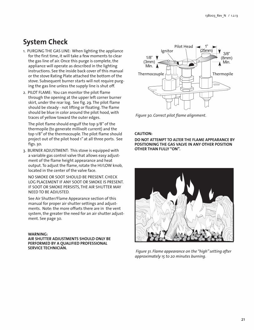
Log Set InstallationNOTE:InstalltheoptionalBrickKit,ifappropriate,beforeinstalling the Log Set. See page 30.The Log Set and Ember Stones are packaged in foam inside the firebox. Handle these parts with gloves to avoid skin irritation. 1. Assemble the Left and Right Rear Logs as shown in
fig 28. First engage the halves together, and then engagethepinsontheburnerskirtwiththeadjacentholes in the underside of the logs.
2. LocatetheMiddleLogasshowninfig.29.3. Also included is a bag of ember stones that simulate
glowing coals when the burner is operating. These should be spread thinly over the burner plate. NOTE:Keeptheemberstones1/4”awayfromtheedgeoftheBurnerSkirtandPilotAssembly.Seefig.29. All the ember stones do not have to be used.
Figure 27. Accessory wiring diagram.
Figure 28. Install Rear Log.
�������������
�����
����������
������������������
���������������
��
��
����
������� ����
��
���
����
Figure 29. Middle Log and ember stones in place.
��������
��������
������������� KEEPEMBERSTONESFROM
OBSTRUCTINGPILOTAREA.
21
138003_Rev_N / 1.2.13
System Check1.PURGINGTHEGASLINE:Whenlightingtheappliance
for the first time, it will take a few moments to clear the gas line of air. Once this purge is complete, the appliance will operate as described in the lighting instructions. See the inside back cover of this manual or the stove Rating Plate attached the bottom of the stove. Subsequent burner starts will not require purg-ing the gas line unless the supply line is shut off.
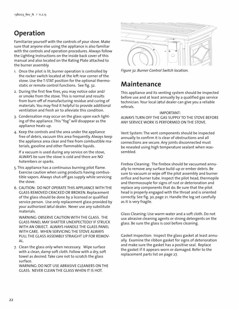
2.PILOTFLAME:Youcanmonitorthepilotflamethrough the opening at the upper left corner burner skirt, under the rear log. See fig. 29. The pilot flame should be steady - not lifting or floating. The flame should be blue in color around the pilot hood, with traces of yellow toward the outer edges.
Thepilotflameshouldengulfthetop3/8”ofthethermopile (to generate millivolt current) and the top1/8”ofthethermocouple.Thepilotflameshouldprojectoutofthepilothood1”atallthreeports.Seefigs. 30.
3.BURNERADJUSTMENT:Thisstoveisequippedwithavariablegascontrolvalvethatallowseasyadjust-ment of the flame height appearance and heat output.Toadjusttheflame,rotatetheHI/LOWknob,located in the center of the valve face.
NOSMOKEORSOOTSHOULDBEPRESENT.CHECKLOGPLACEMENTIFANYSOOTORSMOKEISPRESENT.IFSOOTORSMOKEPERSISTS,THEAIRSHUTTERMAYNEED TO BE ADJUSTED.
See Air Shutter/Flame Appearance section of this manualforproperairshuttersettingsandadjust-ments. Note: the more offsets there are in the vent system,thegreatertheneedforanairshutteradjust-ment. See page 30.
Figure 31. Flame appearance on the “high” setting after approximately 15 to 20 minutes burning.
WARNING: AIRSHUTTERADJUSTMENTSSHOULDONLYBEPERFORMEDBYAQUALIFIEDPROFESSIONALSERVICE TECHNICIAN.
CAUTION:DONOTATTEMPTTOALTERTHEFLAMEAPPEARANCEBYPOSITIONING THE GAS VALVE IN ANY OTHER POSITION OTHER THAN FULLY “ON”.
��������
�������������
�������������
Pilot Head
Thermocouple Thermopile
Ignitor
Figure 30. Correct pilot flame alignment.
22
138003_Rev_N / 11.2.13
MaintenanceThis appliance and its venting system should be inspected before use and at least annually by a qualified gas service technician.YourlocalJøtuldealercangiveyouareliablereferals.
IMPORTANT:ALWAYSTURNOFFTHEGASSUPPLYTOTHESTOVEBEFOREANYSERVICEWORKISPERFORMEDONTHESTOVE. Vent System: The vent components should be inspected annually to confirm it is clear of obstructions and all connectionsaresecure.Anyjointsdisconnectedmustbe resealed using high temperature sealant when reas-sembled.
Firebox Cleaning: The firebox should be vacuumed annu-ally to remove any surface build-up or ember debris. Be sure to vacuum or wipe off the pilot assembly and burner orifice and burner tube. Inspect the pilot head, thermopile and thermocouple for signs of rust or deterioration and replace any components that do. Be sure that the pilot head is properly engaged with the throat and is oriented correctly. See fig. 30, page 21. Handle the log set carefully as it is very fragile.
Glass Cleaning: Use warm water and a soft cloth. Do not use abrasive cleaning agents or strong detergents on the glass. Be sure the glass is cool before cleaning.
Gasket Inspection: Inspect the glass gasket at least annu-ally. Examine the ribbon gasket for signs of deterioration and make sure the gasket has a positive seal. Replace the gasket if it appears worn or damaged. Refer to the replacement parts list on page 27.
OperationFamiliarizeyourselfwiththecontrolsofyourstove.Makesure that anyone else using the appliance is also familiar with the controls and operation procedures. Always follow the Lighting Instructions on the inside back cover of this manual and also located on the Rating Plate attached to the burner assembly.1. Once the pilot is lit, burner operation is controlled by
the rocker switch located at the left rear corner of the stove. Use the T-STAT position for the optional thermo-static or remote control functions. See fig. 32.
2. During the first few fires, you may notice odor and/or smoke from the stove. This is normal and results from burn-off of manufacturing residue and curing of materials.Youmayfindithelpfultoprovideadditionalventilation and fresh air to alleviate this condition.
3. Condensation may occur on the glass upon each light-ingoftheappliance.This“fog”willdisappearastheappliance heats up.
4. Keepthecontrolsandtheareaundertheappliancefree of debris, vacuum this area frequently. Always keep the appliance area clear and free from combustible ma-terials, gasoline and other flammable liquids.
If a vacuum is used during any service on the stove, ALWAYSbesurethestoveiscoldandthereareNOhotembers or sparks.
5. This appliance has a continuous burning pilot flame. Exercise caution when using products having combus-tible vapors. Always shut-off gas supply while servicing the stove.
6. CAUTION:DONOTOPERATETHISAPPLIANCEWITHTHEGLASSREMOVEDCRACKEDORBROKEN. Replacement of the glass should be done by a licensed or qualified service person. Use only replacement glass provided by your authorized Jøtul dealer. Never use any substitute materials.
WARNING:OBSERVECAUTIONWITHTHEGLASS.THEGLASSPANELMAYSHATTERUNEXPECTEDLYIFSTRUCKWITHANOBJECT.ALWAYSHANDLETHEGLASSPANELWITHCARE.WHENSERVICINGTHESTOVEALWAYSPULLTHEGLASSASSEMBLYSTRAIGHTUPFORREMOV-AL.
7.Cleantheglassonlywhennecessary.Wipesurfacewith a clean, damp soft cloth. Follow with a dry, soft towel as desired. Take care not to scratch the glass surface. WARNING:DONOTUSEABRASIVECLEANERSONTHEGLASS.NEVERCLEANTHEGLASSWHENITISHOT.
Figure 32. Burner Control Switch location.
23
138003_Rev_N / 1.2.13
Always replace any damaged or broken parts with JØTULAUTHORIZEDPARTSONLY.Theseareavailablethrough your Jøtul dealer. Never use any substitute parts on your stove.
Withpropercareandmaintenanceyourappliancewillprovideyouwithmanyyearsofenjoyment.Ifyouex-perience any problems or inconsistency with your stove, contact your authorized Jøtul dealer for assistance.
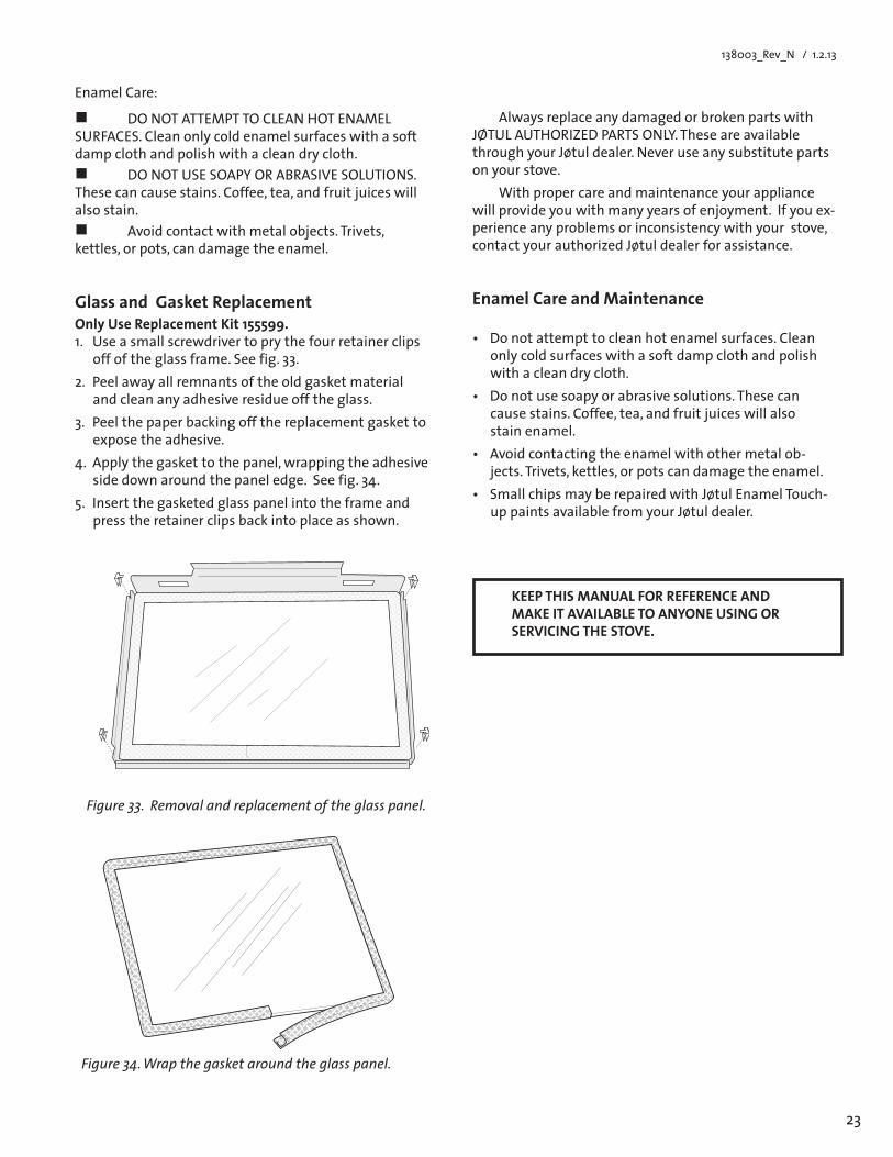
Figure 34. Wrap the gasket around the glass panel.
KEEP THIS MANUAL FOR REFERENCE AND MAKEITAVAILABLETOANYONEUSINGORSERVICING THE STOVE.
Figure 33. Removal and replacement of the glass panel.
Enamel Care:
DONOTATTEMPTTOCLEANHOTENAMELSURFACES. Clean only cold enamel surfaces with a soft damp cloth and polish with a clean dry cloth. DONOTUSESOAPYORABRASIVESOLUTIONS.Thesecancausestains.Coffee,tea,andfruitjuiceswillalso stain. Avoidcontactwithmetalobjects.Trivets,kettles, or pots, can damage the enamel.
Glass and Gasket Replacement Only Use Replacement Kit 155599. 1. Use a small screwdriver to pry the four retainer clips
off of the glass frame. See fig. 33.2. Peel away all remnants of the old gasket material
and clean any adhesive residue off the glass.3. Peel the paper backing off the replacement gasket to
expose the adhesive.4.Applythegaskettothepanel,wrappingtheadhesive
sidedownaroundthepaneledge.Seefig.34.5. Insert the gasketed glass panel into the frame and
press the retainer clips back into place as shown.
Enamel Care and Maintenance
• Donotattempttocleanhotenamelsurfaces.Cleanonly cold surfaces with a soft damp cloth and polish with a clean dry cloth.
• Donotusesoapyorabrasivesolutions.Thesecancausestains.Coffee,tea,andfruitjuiceswillalsostain enamel.
• Avoidcontactingtheenamelwithothermetalob-jects.Trivets,kettles,orpotscandamagetheenamel.
• SmallchipsmayberepairedwithJøtulEnamelTouch-up paints available from your Jøtul dealer.
24
138003_Rev_N / 11.2.13
������
����
���
������
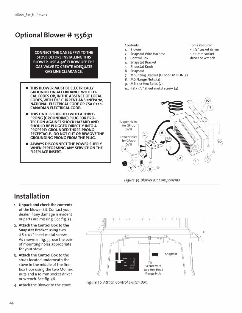
OptionalBlower#155631
Installation1. Unpack and check the contents
of the blower kit. Contact your dealer if any damage is evident or parts are missing. See fig. 35.
2. AttachtheControlBoxtotheSnapstatBracket using two #8x1/2”sheetmetalscrews.As shown in fig. 35, use the pair of mounting holes appropriate for your stove.
3. AttachtheControlBox to the studs located underneath the stove in the middle of the fire-boxfloorusingthetwoM6hexnuts and a 10 mm socket driver orwrench.Seefig.36.
4.AttachtheBlowertothestove.
CONNECT THE GAS SUPPLY TO THE STOVEBEFOREINSTALLINGTHIS
BLOWER.USEA90°ELBOWOFFTHEGAS VALVE TO CREATE ADEQUATE
GAS LINE CLEARANCE.
THISBLOWERMUSTBEELECTRICALLYGROUNDED IN ACCORDANCE WITH LO-CALCODESOR,INTHEABSENCEOFLOCALCODES,WITHTHECURRENTANSI/NFPA70,NATIONAL ELECTRICAL CODE OR CSA C22.1-CANADIAN ELECTRICAL CODE.
THIS UNIT IS SUPPLIED WITH A THREE-PRONG (GROUNDING) PLUG FOR PRO-TECTION AGAINST SHOCK HAZARD AND SHOULDBEPLUGGEDDIRECTLYINTOAPROPERLY GROUNDED THREE-PRONG RECEPTACLE. DO NOT CUT OR REMOVE THE GROUNDING PRONG FROM THE PLUG.
ALWAYS DISCONNECT THE POWER SUPPLY WHEN PERFORMING ANY SERVICE ON THE FIREPLACE INSERT.
Contents 1. Blower 2. SnapstatWireHarness 3. Control Box 4. SnapstatBracket 5. Rheostat Knob 6. Snapstat 7. MountingBracket(GF100DVIIONLY) 8. M6FlangeNuts,(2) 9.M6x12HexBolts,(2) 10.#8x1/2”Sheetmetalscrew,(4)
Tools Required •1/4”socketdriver •10mmsocketdriver or wrench
Figure 36. Attach Control Switch Box.
Secure with two Hex Head
Flange Nuts
Snapstat
Figure 35. Blower Kit Components
12
6
710
9
85 3
4
Upper Holes for GF100
DV II
Lower Holes for GF200
DV II10
10
25
138003_Rev_N / 1.2.13
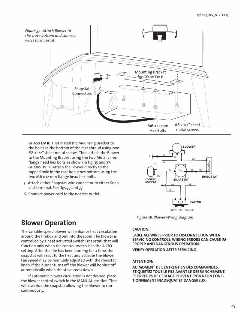
BlowerOperationThe variable-speed blower will enhance heat circulation around the firebox and out into the room. The blower is controlled by a heat activated switch (snapstat) that will function only when the control switch is in the AUTO setting. After the fire has been burning for a time, the snapstat will react to the heat and activate the blower. Fanspeedmaybemanuallyadjustedwiththerheostatknob. If the burner turns off, the blower will be shut off automatically when the stove cools down.
If automatic blower circulation is not desired, place theblowercontrolswitchintheMANUALposition.Thatwill override the snapstat allowing the blower to run continuously.
M6x12mmHex Bolts
Figure 38. Blower Wiring Diagram
CAUTION:LABELALLWIRESPRIORTODISCONNECTIONWHENSERVICING CONTROLS. WIRING ERRORS CAN CAUSE IM-PROPER AND DANGEROUS OPERATION.VERIFY OPERATION AFTER SERVICING.
ATTENTION:AUMOMENTDEL’ENTRENTIENDESCOMMANDES,ETIQUIETEZTOUSLEFILSAVANTLEDEBRANCHEMENT.ESERREURSDECEBLAGEPEUVENTENTRATUNFONC-TIONNEMENT INADEQUAT ET DANGEREUX.
GF 100 DV II: FirstinstalltheMountingBrackettothe holes in the bottom of the rear shroud using two #8x1/2”sheetmetalscrews.ThenattachtheBlowertotheMountingBracketusingthetwoM6x12mmflange head hex bolts as shown in fig. 35 and 37. GF 200 DV II: Attach the Blower directly to the tapped hole in the cast iron stove bottom using the twoM6x12mmflangeheadhexbolts.
5. Attach either Snapstat wire connector to either Snap-stat terminal. See figs.35 and 37.
6. Connectpowercordtothenearestoutlet.
Snapstat Connectors
MountingBracketfor GF100 DV II
#8x1/2”sheetmetal screws
Figure 37 . Attach Blower to the stove bottom and connect wires to Snapstat.
����������
��
������
�����������
�
��������
��
��
������
�������������������
��
��
��
��
��
AUTOOFFMANUAL
26
138003_Rev_N / 11.2.13
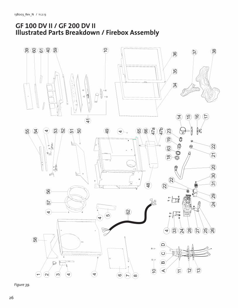
GF 100 DV II / GF 200 DV IIIllustratedPartsBreakdown/FireboxAssembly
Figure 39.
�
� � � �
�
�
�
�
�
�
� � �
�� �� �� ��
�� �� �� �� �� ����
����
����
����
��������
����
��
����
��
���
��
���������������
����
�� �� �� �� �� ��
����
�� �� ��
��
��
��
��
���
�
����
����
�������
������������
����
������
�����
����
������
��������� ���
��
����
���
27
138003_Rev_N / 1.2.13
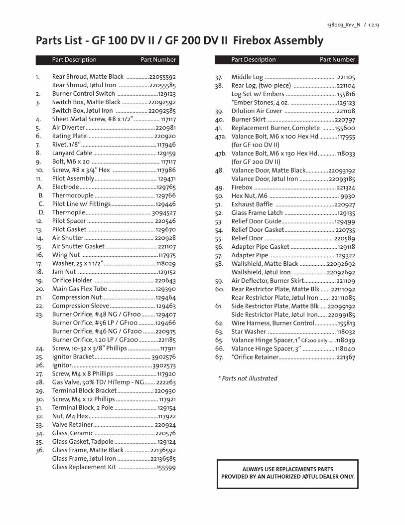
Part Description Part Number
1. RearShroud,MatteBlack ...............22055592 Rear Shroud, Jøtul Iron ....................220555852. Burner Control Switch ...........................1291233. SwitchBox,MatteBlack ................. 22092592 Switch Box, Jøtul Iron ..................... 220925854. SheetMetalScrew,#8x1/2” ................. 117117 5. Air Diverter ..............................................220981 6. RatingPlate ............................................ 2209207. Rivet,1/8” ..................................................1179468. Lanyard Cable .......................................... 1291599. Bolt,M6x20 ............................................. 11711710. Screw,#8x3/4”Hex .............................11798611. Pilot Assembly ......................................... 129471 A. Electrode ...................................................129765 B. Thermocouple ........................................ 129766 C. Pilot Line w/ Fittings .............................129446 D. Thermopile ........................................... 309452712. Pilot Spacer ............................................ 22054613. Pilot Gasket .............................................12967014. AirShutter .............................................. 22092815. Air Shutter Gasket .................................. 221107 16. WingNut ..................................................11797517. Washer,25x11/2” ...................................11802918. Jam Nut .....................................................129152 19. Orifice Holder ....................................... 22064320. MainGasFlexTube ...............................12939021. Compression Nut ...................................12946422. Compression Sleeve .............................. 12946323. BurnerOrifice,#48NG/GF100 ......... 129407 BurnerOrifice,#56LP/GF100 ...........129466 BurnerOrifice,#46NG/GF200 ........220975 Burner Orifice, 1.20 LP / GF200 .............221185 24. Screw,10-32x3/8”Phillips .....................117911 25. Ignitor Bracket ..................................... 390257626. Ignitor .....................................................3902573 27. Screw,M4x8Phillips ........................... 117920 28. Gas Valve, 50% TD/ HiTemp - NG ....... 222263 29. Terminal Block Bracket ........................ 22093030. Screw,M4x12Phillips ............................ 11792131. Terminal Block, 2 Pole ............................ 12915432. Nut,M4Hex ..............................................11792233. Valve Retainer ........................................ 22092434. Glass,Ceramic ........................................22057635. Glass Gasket, Tadpole ............................ 12912436. GlassFrame,MatteBlack ................ 22136592 Glass Frame, Jøtul Iron ......................22136585 Glass Replacement Kit .........................155599
Parts List - GF 100 DV II / GF 200 DV II Firebox Assembly
ALWAYS USE REPLACEMENTS PARTS PROVIDEDBYANAUTHORIZEDJØTULDEALERONLY.
37. MiddleLog .............................................. 22110538. Rear Log, (two-piece) ............................221104 Log Set w/ Embers ................................. 155816 *EmberStones,4oz. ...............................12912339. Dilution Air Cover ..................................22110840. BurnerSkirt ............................................22079741. ReplacementBurner,Complete ........15560047a. ValanceBolt,M6x100HexHd ............117955 (for GF 100 DV II)47b. ValanceBolt,M6x130HexHd ............ 118033 (for GF 200 DV II)48. ValanceDoor,MatteBlack ...............22093192 Valance Door, Jøtul Iron ...................2209318549. Firebox ......................................................22132450. HexNut,M6 .............................................. 993051. Exhaust Baffle .......................................22092752. Glass Frame Latch ...................................12913553. Relief Door Guide...................................12949954. ReliefDoorGasket ................................. 22073555. Relief Door ............................................. 22058956. AdapterPipeGasket ...............................12911857. Adapter Pipe ...........................................12932258. Wallshield,MatteBlack ..................22092692 Wallshield,JøtulIron ......................2209269259. Air Deflector, Burner Skirt .....................22110960. RearRestrictorPlate,MatteBlk ...... 22111092 Rear Restrictor Plate, Jøtul Iron ....... 2211108561. SideRestrictorPlate,MatteBlk ..... 22099192 Side Restrictor Plate, Jøtul Iron ...... 2209918562. WireHarness,BurnerControl ...............15581363. StarWasher ............................................. 11803265. ValanceHingeSpacer,1”GF200 only .......11803966. ValanceHingeSpacer,3” ..................... 11804067. *OrificeRetainer ......................................221367
Part Description Part Number
* Parts not illustrated
28
138003_Rev_N / 11.2.13
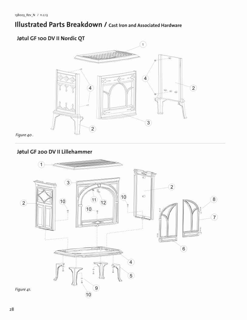
Jøtul GF 200 DV II Lillehammer
IllustratedPartsBreakdown/CastIronandAssociatedHardware
Jøtul GF 100 DV II Nordic QT
�
�
�
�
�
�
�
�
�
����
��
��
���
��
Figure 41.
Figure 40 .
�
�
�
�
�
�
29
138003_Rev_N / 1.2.13
Cast Iron Parts List
Jøtul GF 200 DV II Lillehammer
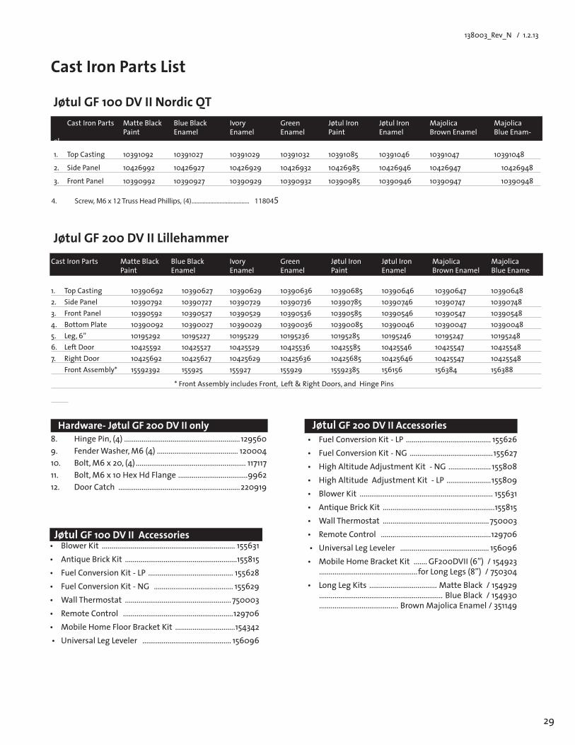
4. Screw, M6 x 12 Truss Head Phillips, (4) ..................................... 118045
CastIronPartsMatteBlack BlueBlack Ivory Green JøtulIron JøtulIron Majolica Majolica Paint Enamel Enamel Enamel Paint Enamel Brown Enamel Blue Enam-el
1. TopCasting 10391092 10391027 10391029 10391032 10391085 10391046 10391047 10391048
2. SidePanel 10426992 10426927 10426929 10426932 10426985 10426946 10426947 10426948
3. FrontPanel 10390992 10390927 10390929 10390932 10390985 10390946 10390947 10390948
Jøtul GF 100 DV II Nordic QT
CastIronParts MatteBlack BlueBlack Ivory Green JøtulIron JøtulIron Majolica Majolica Paint Enamel Enamel Enamel Paint Enamel Brown Enamel Blue Ename
1. TopCasting 10390692 10390627 10390629 10390636 10390685 10390646 10390647 103906482. SidePanel 10390792 10390727 10390729 10390736 10390785 10390746 10390747 103907483. FrontPanel 10390592 10390527 10390529 10390536 10390585 10390546 10390547 103905484. BottomPlate 10390092 10390027 10390029 10390036 10390085 10390046 10390047 103900485. Leg,6” 10195292 10195227 10195229 10195236 10195285 10195246 10195247 101952486. LeftDoor 10425592 10425527 10425529 10425536 10425585 10425546 10425547 104255487. RightDoor 10425692 10425627 10425629 10425636 10425685 10425646 10425547 10425548 FrontAssembly* 15592392 155925 155927 155929 15592385 156156 156384 156388
*FrontAssemblyincludesFront,Left&RightDoors,andHingePins
8. HingePin,(4) ............................................................1295609. FenderWasher,M6(4) .......................................... 12000410. Bolt,M6x20,(4) ......................................................... 11711711. Bolt,M6x10HexHdFlange ....................................996212. Door Catch ...............................................................220919
Hardware-JøtulGF200DVIIonly Jøtul GF 200 DV II Accessories• FuelConversionKit-LP ............................................ 155626• FuelConversionKit-NG ...........................................155627• HighAltitudeAdjustmentKit-NG ...................... 155808• HighAltitudeAdjustmentKit-LP .......................155809• BlowerKit ..................................................................... 155631• AntiqueBrickKit ..........................................................155815• WallThermostat .......................................................750003• RemoteControl .........................................................129706• UniversalLegLeveler .............................................. 156096• MobileHomeBracketKit .......GF200DVII(6”)/154923
...................................................forLongLegs(8”)/750304• LongLegKits ...................................MatteBlack/154929
................................................................ BlueBlack/154930 .........................................BrownMajolicaEnamel/351149
Jøtul GF 100 DV II Accessories• BlowerKit ..................................................................... 155631• AntiqueBrickKit ..........................................................155815• FuelConversionKit-LP ............................................ 155628• FuelConversionKit-NG ......................................... 155629• WallThermostat .......................................................750003• RemoteControl .........................................................129706• MobileHomeFloorBracketKit ...............................154342• UniversalLegLeveler .............................................. 156096
30
138003_Rev_N / 11.2.13
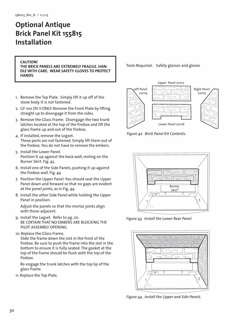
Optional Antique BrickPanelKit155815 Installation
1. Remove the Top Plate. Simply lift it up off of the stove body. It is not fastened.
2. GF100DVIIONLY:RemovetheFrontPlatebyliftingstraight up to disengage it from the sides.
3. Remove the Glass Frame. Disengage the two trunk latches located at the top of the firebox and lift the glass frame up and out of the firebox.
4. Ifinstalled,removetheLogset. These parts are not fastened. Simply lift them out of thefirebox.Youdonothavetoremovetheembers.
5. Install the Lower Panel. Position it up against the back wall, resting on the BurnerSkirt.Fig.43.
6. InstalloneoftheSidePanels,pushingitupagainstthefireboxwall.Fig.44
7. PositiontheUpperPanel.YoushouldseattheUpperPanel down and forward so that no gaps are evident atthepaneljoints,asinFig.44.
8. Install the other Side Panel while holding the Upper Panel in position.
Adjustthepanelssothatthemortarjointsalignwiththoseadjacent.
9. Install the Logset. Refer to pg. 20. BECERTAINTHATNOEMBERSAREBLOCKINGTHEPILOTASSEMBLYOPENING.
10. Replace the Glass Frame. Slide the frame down the slot in the front of the firebox. Be sure to push the frame into the slot in the bottom to ensure it is fully seated. The gasket at the top of the frame should be flush with the top of the firebox.
Re-engage the trunk latches with the top lip of the glass frame.
11. Replace the Top Plate.
Tools Required: Safety glasses and gloves
Figure 44 . Install the Upper and Side Panels.
LowerPanel221116
Right Panel 221115
Upper Panel 221117
Left Panel 221114
Figure 43. Install the Lower Rear Panel
Burner Skirt
CAUTION! THEBRICKPANELSAREEXTREMELYFRAGILE.HAN-DLE WITH CARE. WEAR SAFETY GLOVES TO PROTECT HANDS.
Figure 42. Brick Panel Kit Contents.
31
138003_Rev_N / 1.2.13
Effective January 1, 2013This warranty policy applies to gas products identified by Jøtul, Scan, and Atra trade names, as set forth below.A.LIMITEDFIVEYEARWARRANTY-CastIron,SteelDoors,Surround Components, Firebox:Jøtul North America Inc. (JØTUL) warrants, to the original retail purchaser, that those components of the Jøtul, Scan, or Atra Gas Stove or Fireplace specified above will be free of defects in material and workmanship for a period of five (5) years from thedateofpurchase.Thiswarrantyissubjecttotheterms,exclusions and limitations set forth in the following text.B.LIMITEDTWOYEARWARRANTY-Burner,BurnerTreatments,Firebox Panels: JØTUL warrants, to the original retail purchaser, that those components of the Jøtul, Scan, or Atra Gas Stove or Fireplace specified above will be free of defects in material and workmanship for a period of two (2) years from the date of purchase.Thiswarrantyissubjecttotheterms,exclusions,andlimitations set forth in the following text.C.LIMITEDTWOYEARWARRANTY-EnamelFinish:JØTUL warrants, to the original retail purchaser, the enamel finish on cast iron components of the Jøtul Stove or Fireplace Insert specified above against peeling or fading for a period of two(2)yearsfromthedateofpurchase.Thiswarrantyissubjectto the terms, exclusions and limitations set forth below.D.LIMITEDONEYEARWARRANTY-Gas&ElectricalComponents(controls, plumbing, valve, blower): JØTUL warrants, to the original retail purchaser, that those components of the Jøtul, Scan, or Atra Gas Stove or Fireplace specified above will be free of defects in material and workmanship for a period of one (1) year from the date of purchase.Thiswarrantyissubjecttotheterms,exclusions,andlimitations set forth in the following text.JØTULwillrepairorreplace(includingparts&labor),atitsoption,anyof the above components determined by JØTUL to be covered by this warranty.Youmust,atyourownexpense,arrangetodeliverorshipthecomponent to an authorized Jøtul, Scan, or Atra dealer and arrange for pickup or delivery of the component after repairs have been made. If, upon inspection, JØTUL determines that the component is covered by this warranty, the repair or replacement will be made as set forth above. This warranty is not transferable and is extended only to, and is solely for the benefit of, the original retail purchaser of the Jøtul, Scan, or Atra Gas Stove or Fireplace. This paragraph sets forth the sole remedy available under this warranty in the event of any defect in the Jøtul, Scan, or Atra Gas Stove or Fireplace.The warranty period for any replaced component will be the remaining unexpired portion of the warranty period for the original component.Please retain your dated sales receipt in your records as proof of purchase.
EXCLUSIONSANDLIMITATIONSNOTICE: This warranty is void if installation or service is performed by someone other than an authorized installer, service agency or gas supplier, or if installation is not in conformance with the installation and operating instructions contained in this owner’s manual or local and/or national fire and building regulations. A listing of local authorized installers, service agencies and gas suppliers can be obtained from the National Fireplace Institute at http://www.nficertified.org/. This warranty does not cover the following:1) Repairorreplacementofpartsthataresubjecttonormalwearand
tear during the warranty period or to parts that may require replace-ment in connection with normal maintenance. These parts include
gaskets and glass (except to the extent such parts suffer damage from thermal stress).
2) Damage due to incorrect installations not in conformance with the installa-tion instructions contained in this owner’s manual or local and/or national fire and building regulations.
3) Damage due to service performed by an installer, service agency or gas sup-plier, unless otherwise agreed to in writing by JØTUL.
4) Labororothercostsassociatedwiththerepairofgascontrols,plumbing,burners, log set, or sheet metal firebox beyond the warranty period.
5) Damage to enamel finish including chipping, mechanical or chemical abra-sion, crazing, staining, or rust caused by high humidity or salt air environ-ments.
6) Damagetoenameledsurfacescausedbyimproperoperationormisuse,including use that is not in conformance with the operating instructions contained in this owner’s manual. Such damage can typically be identified by bubbling, cracking, or discoloration of the enamel finish.
7) Damage caused by unauthorized modification, use or repair.8) Costs incurred by travel time and/or loss of service.9) Damage incurred while the Jøtul, Scan, or Atra Gas Stove or Fireplace is in
transit.INNOEVENTSHALLJØTUL,ITSPARENTCOMPANY,SHAREHOLDERS,AFFILIATES,OFFICERS,EMPLOYEES,AGENTSORREPRESENTATIVESBELIABLEORRESPONSIBLETOYOUFORANYSPECIAL,INDIRECT,INCIDENTAL,CONSEQUENTIAL,PUNITIVEOROTHERSIMILARDAMAGES,INCLUDING,BUTNOTLIMITEDTO,LOSTPROFITS,LOSTSALES,INJURYTOPERSONORPROPERTY,ORDAMAGESTOASTRUCTUREORITSCONTENTS,ARISINGUNDERANYTHEORYOFLAWWHATSOEVER.ALLIMPLIEDWARRANTIES,INCLUDINGTHEIMPLIEDWARRANTIESOFMERCHANTABILITYANDFITNESSFORAPARTICULARPURPOSE,OROTHERWISE,ARELIMITEDINDURATIONTOTHELENGTHOFTHISWRITTENWARRANTY.EXCEPTASEXPRESSLYSETFORTHHEREIN,JØTULMAKESNOORAL,WRITTENOROTHERWARRANTYWITHRESPECTTO JØTUL, SCAN OR ATRA GAS STOVES OR FIREPLACES.Some states do not allow the exclusion or limitation of incidental or consequential damages, or limitations on the length of implied warranties. Therefore, the above exclusions or limitations may not apply to you. This warranty gives you specific legal rights, and you may have other rights, which vary from state to state. JØTUL reserves the right to discontinue, modify or change the materials used to produce the Jøtul, Scan, or Atra Gas Stove or Fireplace. JØTUL shall have the right to replace any defective component with substitute components determined by JØTUL to be of substantially equal quality and price. The dollar value of JØTUL’s liability for breach of this warranty shall be limited exclusively to the cost of furnishing a replacement component. JØTUL shall not in any event be liable for the cost of labor expended by others in connection with any defective component. Any costs or expenses beyond those expressly assumed by JØTUL under the terms of this warranty shall be the sole responsibility of the owner(s) of the Jøtul, Scan, or Atra Gas Stove or Fireplace.No dealer, distributor, or other person is authorized to modify, augment, or extendthislimitedwarrantyonbehalfofJØTUL.NOMODIFICATIONORCHANGETOTHISWARRANTYWILLBEEFFECTIVEUNLESSITISMADEINAWRITTENDOCUMENTMANUALLYSIGNEDBYANAUTHORIZEDOFFICEROFJØTUL.An authorized installer may have been provided with certain information related particularly to the Jøtul, Scan, or Atra Gas Stove or Fireplace; however, no authorized installer or other person who may service the appliance is an agent of JØTUL. No inference should be made that JØTUL has tested, certified, or otherwise pronounced any person as qualified to install or service the appliance. JØTUL shall not be liable or otherwise responsible for any error or omission by a person installing or servicing a Jøtul, Scan, or Atra Gas Stove or Fireplace.If you believe your Jøtul, Scan, or Atra Gas Stove or Fireplace is defective, you should contact your nearest authorized Jøtul, Scan, or Atra dealer, who will processawarrantyclaim.INORDERTOQUALIFYFORWARRANTYCOVERAGE,JØTULMUSTRECEIVENOTICEOFAPOSSIBLEDEFECTWITHINSIXTY(60)DAYSOFTHEDATETHEDEFECTISFIRSTDISCOVERED,ORREASONABLYCOULDHAVEBEENDISCOVERED.
This warranty is given by Jøtul North America, Inc., 55HutchersonDrive,Gorham,Maine04038USA
Jøtul Gas Product Limited Lifetime Warranty

32
138003_Rev_N / 11.2.13
This page is intentionally blank.

33
138003_Rev_N / 1.2.13
This page is intentionally blank.

34
138003_Rev_N / 11.2.13
This page is intentionally blank.
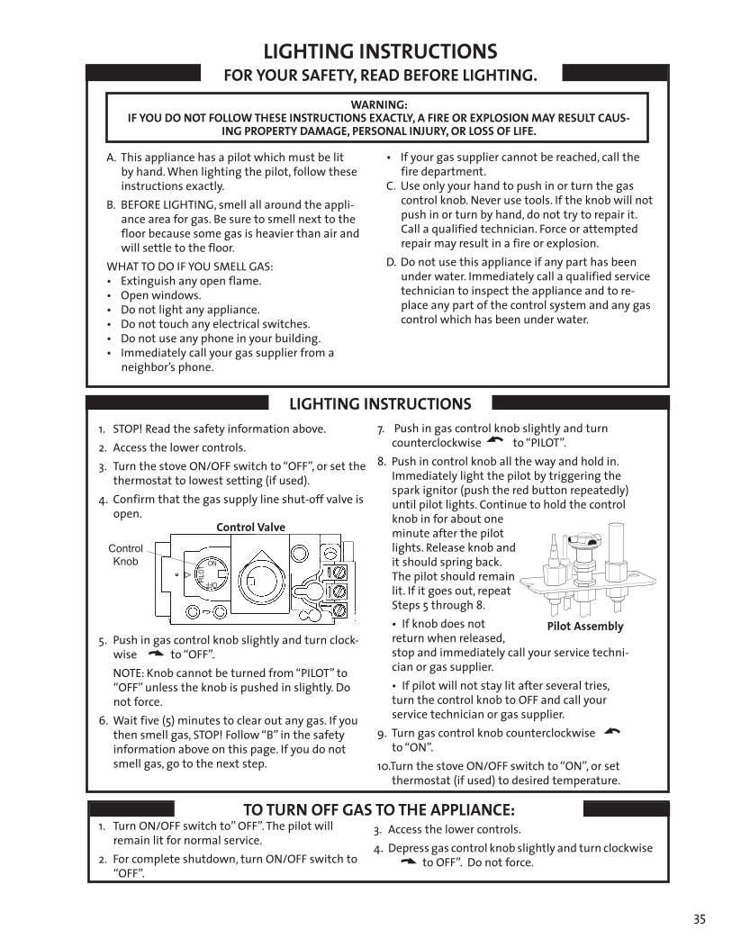
35
138003_Rev_N / 1.2.13
5. Push in gas control knob slightly and turn clock-wiseto“OFF”.
NOTE:Knobcannotbeturnedfrom“PILOT”to“OFF”unlesstheknobispushedinslightly.Donot force.
6. Waitfive(5)minutestoclearoutanygas.Ifyouthensmellgas,STOP!Follow“B”inthesafetyinformation above on this page. If you do not smell gas, go to the next step.
1. TurnON/OFFswitchto”OFF”.Thepilotwillremain lit for normal service.
2. For complete shutdown, turn ON/OFF switch to “OFF”.
FORYOURSAFETY,READBEFORELIGHTING.
LIGHTING INSTRUCTIONS
TO TURN OFF GAS TO THE APPLIANCE:
LIGHTING INSTRUCTIONS
WARNING:IFYOUDONOTFOLLOWTHESEINSTRUCTIONSEXACTLY,AFIREOREXPLOSIONMAYRESULTCAUS-
INGPROPERTYDAMAGE,PERSONALINJURY,ORLOSSOFLIFE.
A. This appliance has a pilot which must be lit byhand.Whenlightingthepilot,followtheseinstructions exactly.
B. BEFORE LIGHTING, smell all around the appli-ance area for gas. Be sure to smell next to the floor because some gas is heavier than air and will settle to the floor.
WHATTODOIFYOUSMELLGAS:• Extinguishanyopenflame.• Openwindows.• Donotlightanyappliance.• Donottouchanyelectricalswitches.• Donotuseanyphoneinyourbuilding.• Immediatelycallyourgassupplierfroma
neighbor’s phone.
• Ifyourgassuppliercannotbereached,callthefire department.
C. Use only your hand to push in or turn the gas control knob. Never use tools. If the knob will not push in or turn by hand, do not try to repair it. Call a qualified technician. Force or attempted repair may result in a fire or explosion.
D. Do not use this appliance if any part has been under water. Immediately call a qualified service technician to inspect the appliance and to re-place any part of the control system and any gas control which has been under water.
1. STOP! Read the safety information above.2. Access the lower controls.3.TurnthestoveON/OFFswitchto“OFF”,orsetthe
thermostat to lowest setting (if used). 4.Confirmthatthegassupplylineshut-offvalveis
open.
Pilot Assembly
7. Push in gas control knob slightly and turn counterclockwiseto“PILOT”.
8. Push in control knob all the way and hold in. Immediately light the pilot by triggering the spark ignitor (push the red button repeatedly) until pilot lights. Continue to hold the control knob in for about one minute after the pilot lights. Release knob and it should spring back. The pilot should remain lit. If it goes out, repeat Steps 5 through 8.
•Ifknobdoesnotreturn when released, stop and immediately call your service techni-cian or gas supplier.
•Ifpilotwillnotstaylitafterseveraltries,turn the control knob to OFF and call your service technician or gas supplier.
9. Turn gas control knob counterclockwise to“ON”.
10.TurnthestoveON/OFFswitchto“ON”,orsetthermostat (if used) to desired temperature.
Control Knob
OFF PILOT ON
3. Access the lower controls.4.Depressgascontrolknobslightlyandturnclockwise
toOFF”.Donotforce.
Control Valve
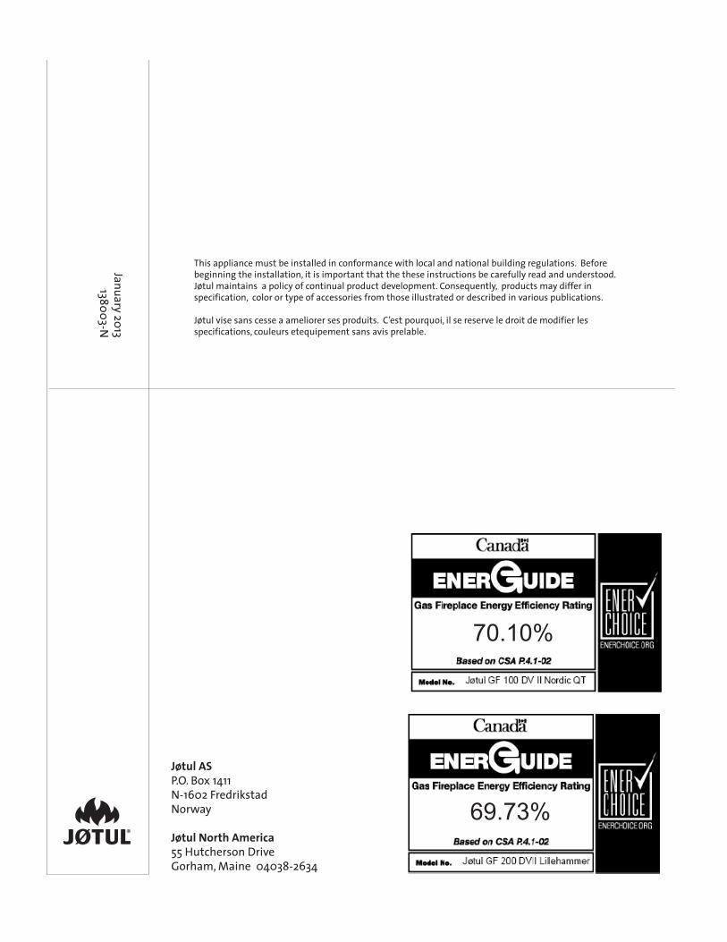
36
138003_Rev_N / 11.2.13
Jøtul ASP.O.Box1411N-1602FredrikstadNorway
Jøtul North America55 Hutcherson DriveGorham,Maine04038-2634
January 2013 138003-N
This appliance must be installed in conformance with local and national building regulations. Before beginning the installation, it is important that the these instructions be carefully read and understood. Jøtul maintains a policy of continual product development. Consequently, products may differ in specification, color or type of accessories from those illustrated or described in various publications.
Jøtul vise sans cesse a ameliorer ses produits. C’est pourquoi, il se reserve le droit de modifier les specifications, couleurs etequipement sans avis prelable.
70.10%
69.73%