Embed Size (px)
Citation preview

Assisted Discovery of On-Chip Debug Interfaces Joe Grand, Grand Idea Studio, Inc.
www.jtagulator.com
Introduction
• On-chip debug interfaces are a well-known attack vector
- Used as a stepping stone to further an attack- Extract program code or data- Modify memory contents- Affect device operation on-the-fly- Can provide chip-level control of a target device
• Identifying OCD interfaces can sometimes be difficult and/or time consuming
Goals
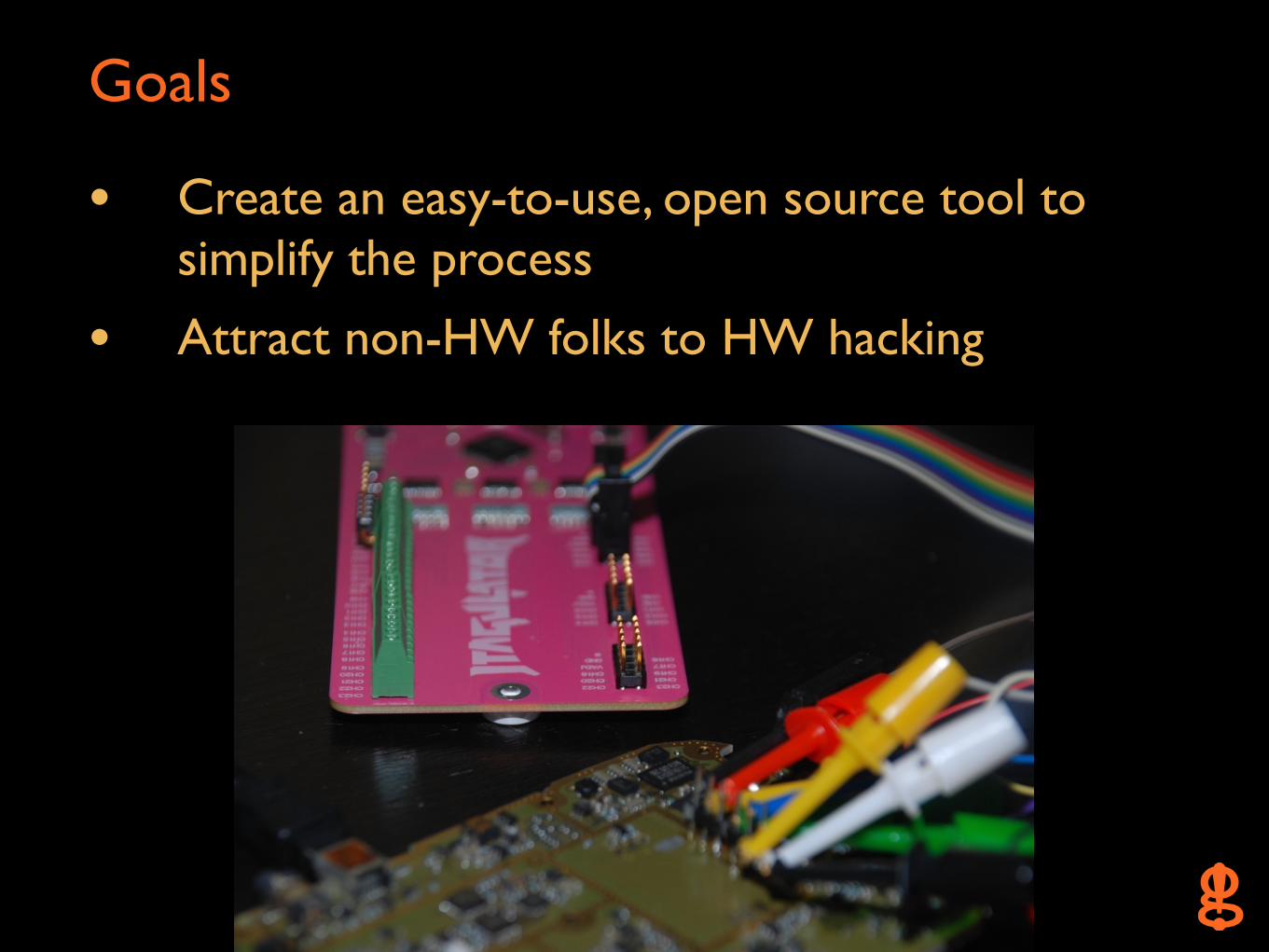
• Create an easy-to-use, open source tool to simplify the process
• Attract non-HW folks to HW hacking
• Hunz's JTAG Finder - http://elinux.org/JTAG_Finder
• JTAGenum & RS232enum - http://deadhacker.com/tools/
• DARPA Cyber Fast Track - www.cft.usma.edu
Inspiration

Other Art
• An Open JTAG Debugger (GoodFET), Travis Goodspeed, DEFCON 17
- http://defcon.org/html/links/dc-archives/dc-17-archive.html#Goodspeed2
• Blackbox JTAG Reverse Engineering, Felix Domke, 26C3
- http://events.ccc.de/congress/2009/Fahrplan/attachments/1435_JTAG.pdf

Other Art 2
• Forensic Imaging of Embedded Systems using JTAG, Marcel Breeuwsma (NFI), Digital Investigation Journal, March 2006
- http://www.sciencedirect.com/science/article/pii/S174228760600003X
Design Requirements
• Open source/hackable/expandable
• Simple command-based interface
• Input protection
• Adjustable target voltage
• Off-the-shelf components
• Hand solderable
Hardware
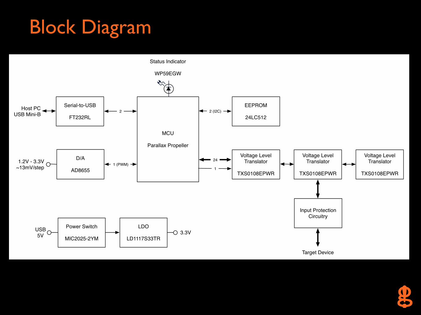
Block Diagram
MCU
Parallax Propeller
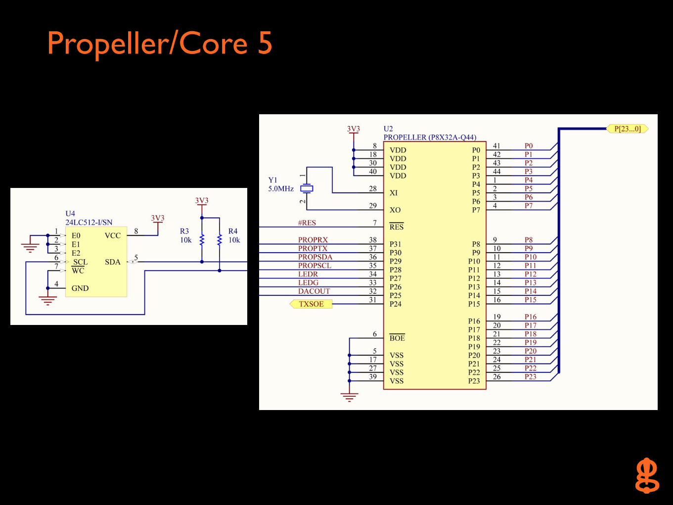
EEPROM
24LC5122 (I2C)
Power Switch
MIC2025-2YM
LDO
LD1117S33TRUSB5V 3.3V
D/A
AD86551.2V - 3.3V
~13mV/step
Serial-to-USB
FT232RL2
1 (PWM)
Host PCUSB Mini-B
Voltage Level Translator
TXS0108EPWR
Voltage Level Translator
TXS0108EPWR
Voltage Level Translator
TXS0108EPWR
Input Protection Circuitry
24
Target Device
1
Status Indicator
WP59EGW
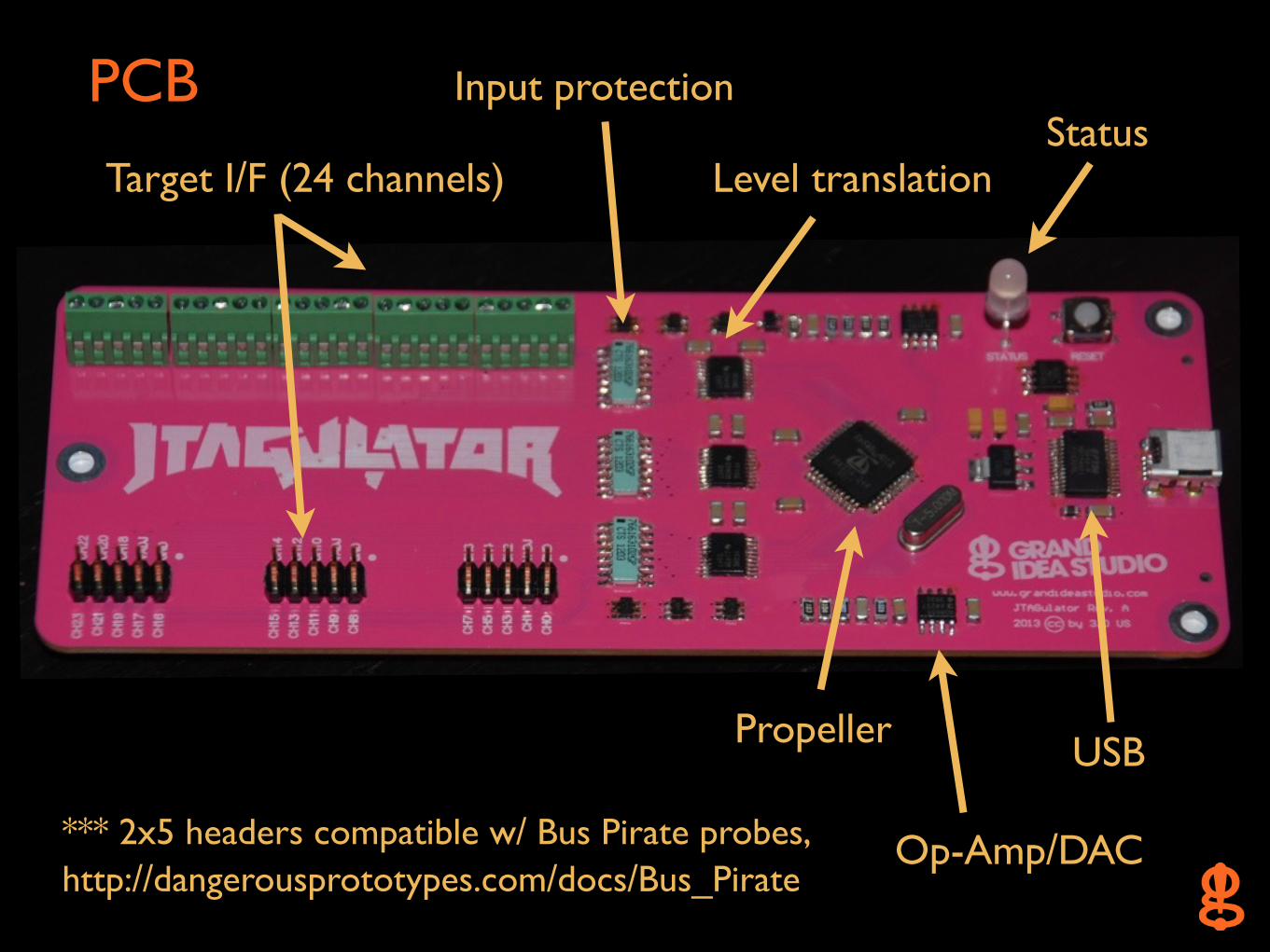
PCB
*** 2x5 headers compatible w/ Bus Pirate probes, http://dangerousprototypes.com/docs/Bus_Pirate
Target I/F (24 channels)
Propeller USB
Input protection
Level translationStatus
Op-Amp/DAC

*** INFORMATION: www.parallax.com/propeller/
*** DISCUSSION FORUMS: forums.parallax.com
*** OBJECT EXCHANGE: obex.parallax.com
• Completely custom, ground up, open source
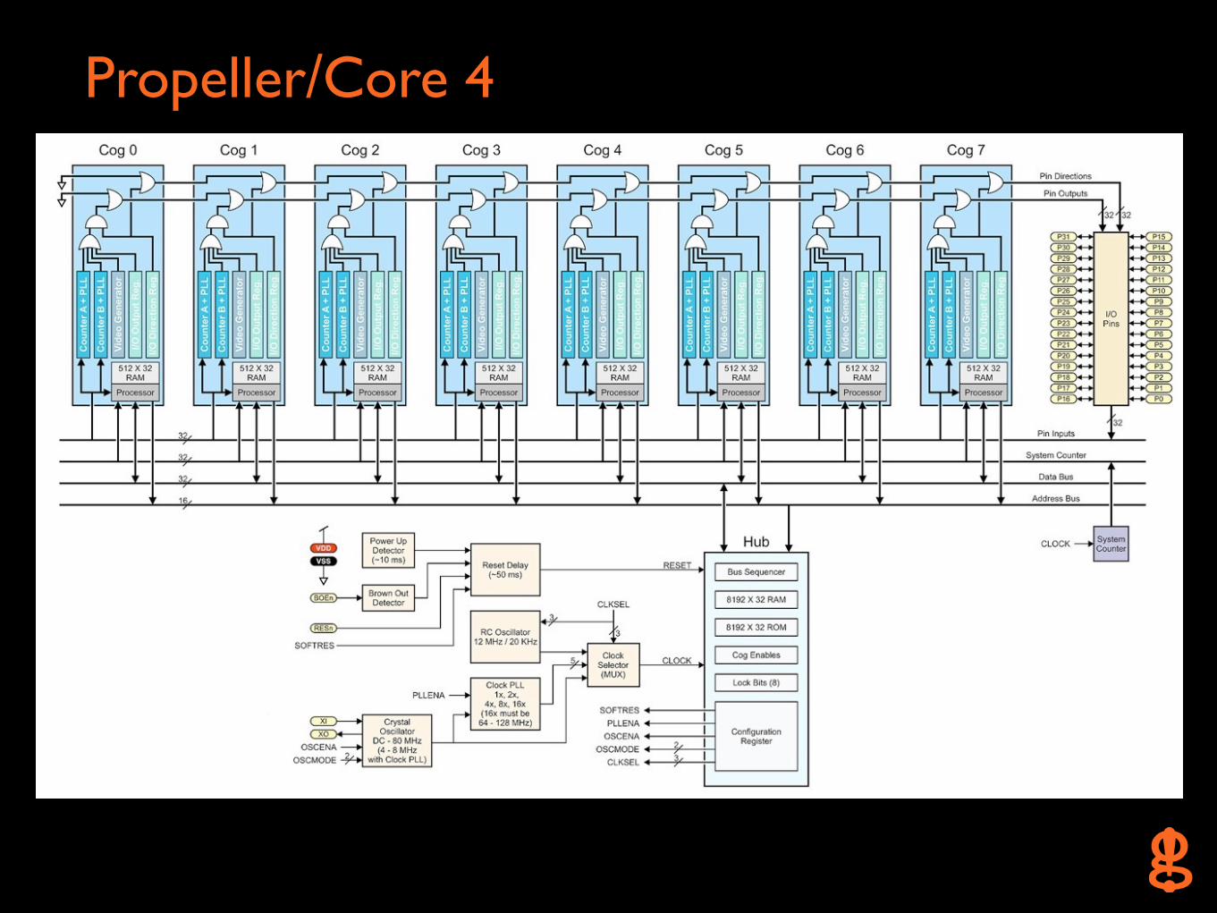
• 8 parallel 32-bit processors (cogs)
• Code in Spin, ASM, or C
Propeller/Core
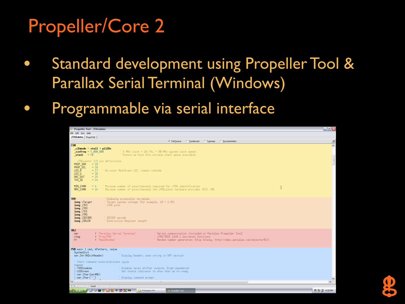
• Standard development using Propeller Tool & Parallax Serial Terminal (Windows)
• Programmable via serial interface
Propeller/Core 2
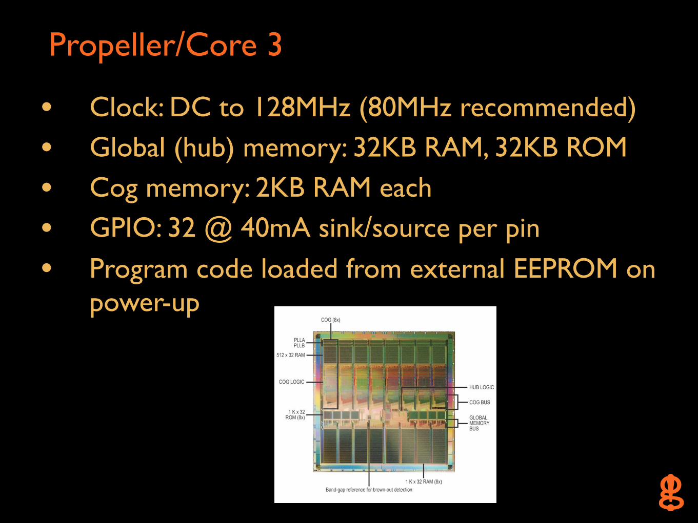
• Clock: DC to 128MHz (80MHz recommended)
• Global (hub) memory: 32KB RAM, 32KB ROM
• Cog memory: 2KB RAM each
• GPIO: 32 @ 40mA sink/source per pin
• Program code loaded from external EEPROM on power-up
Propeller/Core 3
Propeller/Core 4
Propeller/Core 5
USB Interface
• Allows for Propeller programming & UI
• Powers JTAGulator from bus (5V)
• FT232RL USB-to-Serial UART - Entire USB protocol handled on-chip- Host will recognize as a virtual serial device/COM port
(Windows, OS X, Linux)
• MIC2025 Power Distribution Switch - Internal current limiting, thermal shutdown- Let the FT232 enumerate first (@ < 100mA), then
enable system load
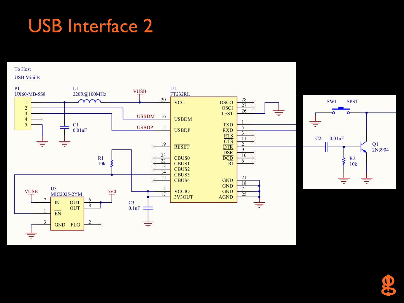
USB Interface 2

Adjustable Target Voltage (VADJ)• PWM from Propeller - Duty cycle corresponds to output voltage- Look-up table in 0.1V increments (1.2V-3.3V)
• AD8655 Low Noise, Precision CMOS Amplifier - Single supply, rail-to-rail- Voltage follower configuration- ~150mA output current @ Vo = 1.2V-3.3V
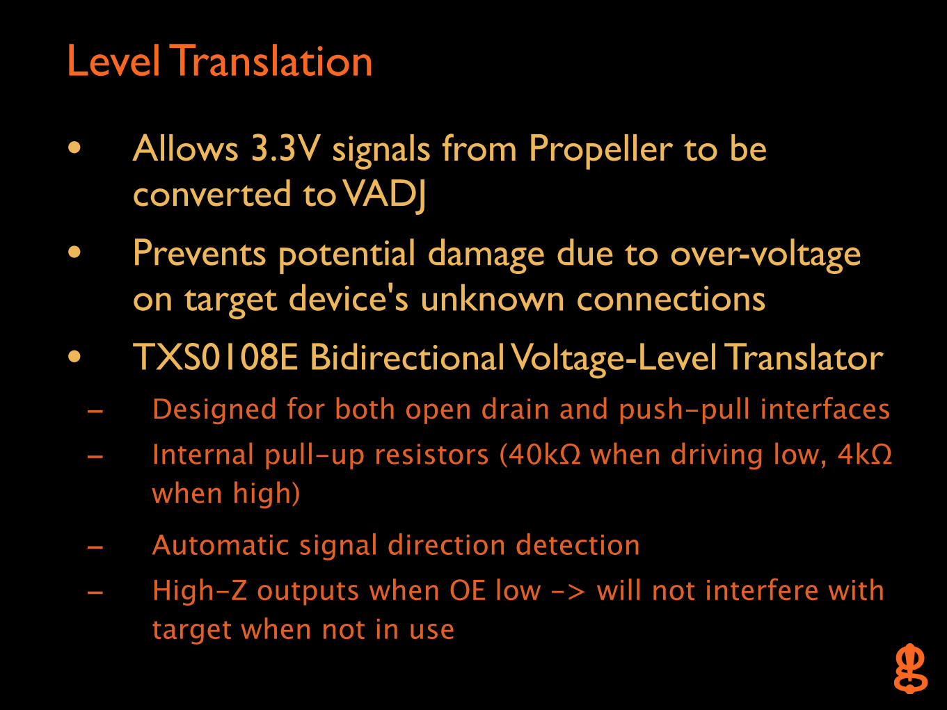
Level Translation
• Allows 3.3V signals from Propeller to be converted to VADJ
• Prevents potential damage due to over-voltage on target device's unknown connections
• TXS0108E Bidirectional Voltage-Level Translator - Designed for both open drain and push-pull interfaces- Internal pull-up resistors (40kΩ when driving low, 4kΩ
when high)
- Automatic signal direction detection- High-Z outputs when OE low -> will not interfere with
target when not in use
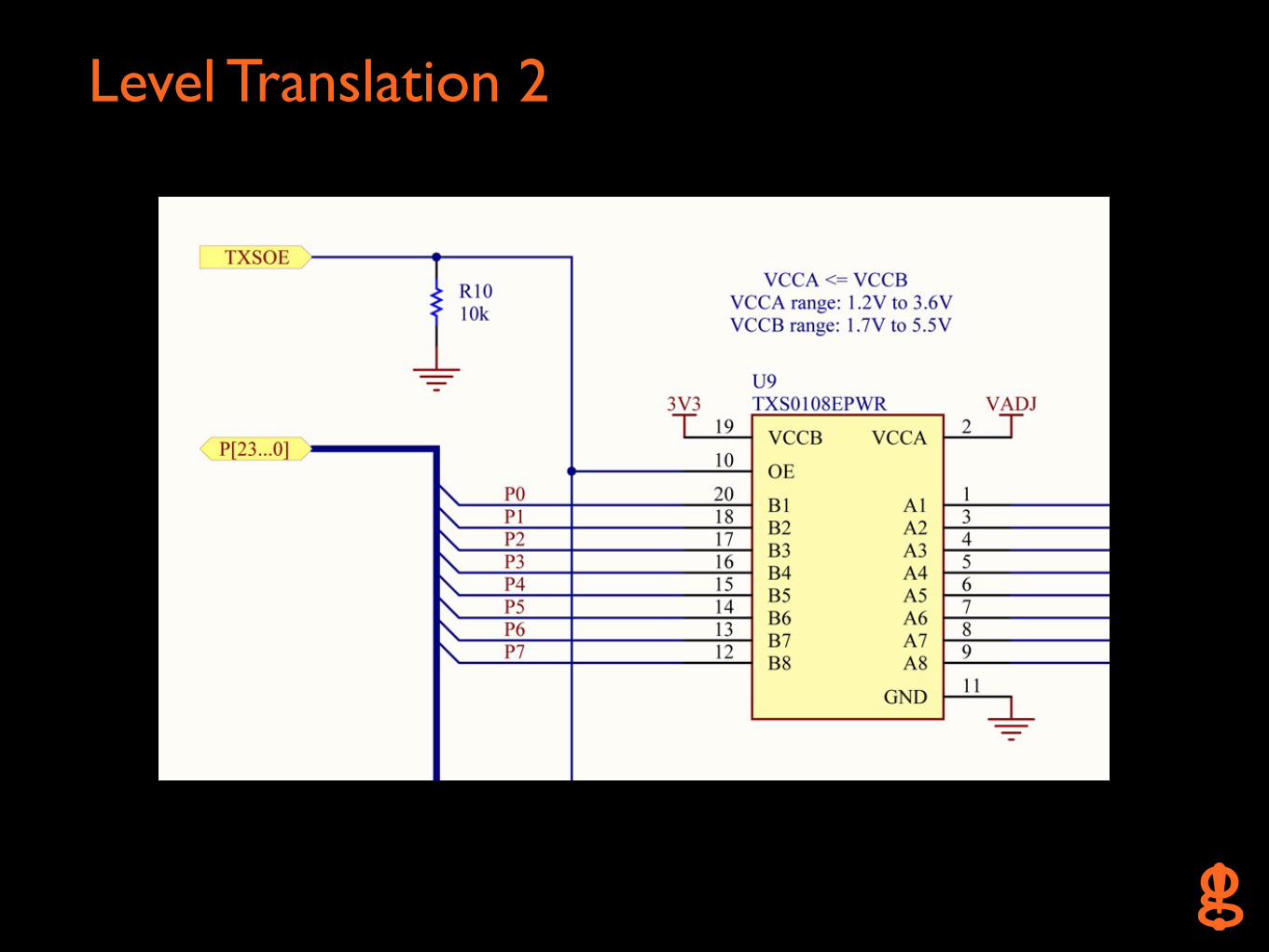
Level Translation 2
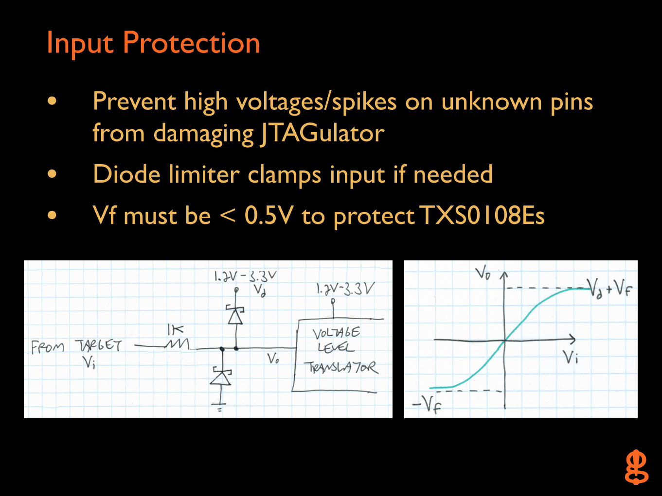
Input Protection
• Prevent high voltages/spikes on unknown pins from damaging JTAGulator
• Diode limiter clamps input if needed
• Vf must be < 0.5V to protect TXS0108Es
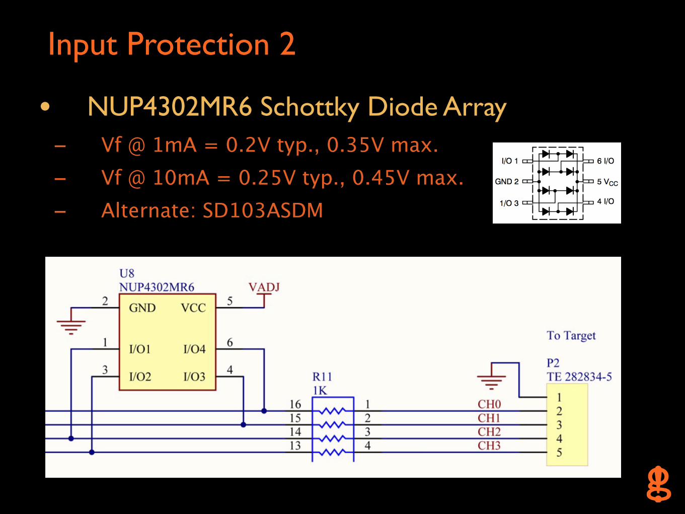
Input Protection 2
• NUP4302MR6 Schottky Diode Array - Vf @ 1mA = 0.2V typ., 0.35V max.- Vf @ 10mA = 0.25V typ., 0.45V max.- Alternate: SD103ASDM
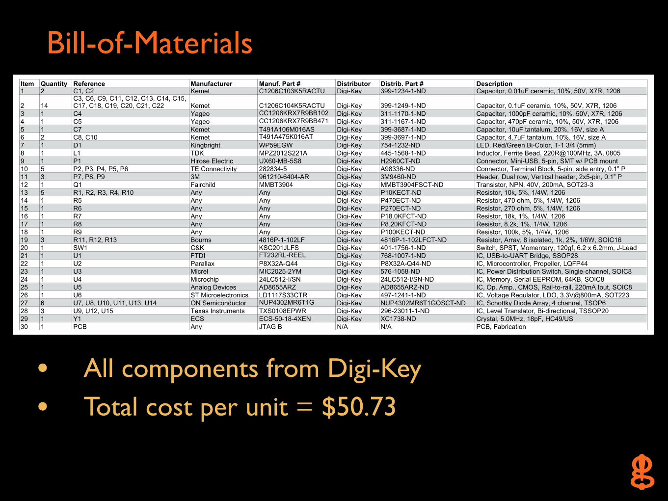
Bill-of-Materials
• All components from Digi-Key
• Total cost per unit = $50.73
JTAGulatorJTAGulatorBill-of-MaterialsBill-of-MaterialsBill-of-MaterialsHW B, Document 1.0, April 19, 2013HW B, Document 1.0, April 19, 2013HW B, Document 1.0, April 19, 2013
Item Quantity Reference Manufacturer Manuf. Part # Distributor Distrib. Part # Description1 2 C1, C2 Kemet C1206C103K5RACTU Digi-Key 399-1234-1-ND Capacitor, 0.01uF ceramic, 10%, 50V, X7R, 1206
2 14C3, C6, C9, C11, C12, C13, C14, C15, C17, C18, C19, C20, C21, C22 Kemet C1206C104K5RACTU Digi-Key 399-1249-1-ND Capacitor, 0.1uF ceramic, 10%, 50V, X7R, 1206
3 1 C4 Yageo CC1206KRX7R9BB102 Digi-Key 311-1170-1-ND Capacitor, 1000pF ceramic, 10%, 50V, X7R, 12064 1 C5 Yageo CC1206KRX7R9BB471 Digi-Key 311-1167-1-ND Capacitor, 470pF ceramic, 10%, 50V, X7R, 12065 1 C7 Kemet T491A106M016AS Digi-Key 399-3687-1-ND Capacitor, 10uF tantalum, 20%, 16V, size A6 2 C8, C10 Kemet T491A475K016AT Digi-Key 399-3697-1-ND Capacitor, 4.7uF tantalum, 10%, 16V, size A7 1 D1 Kingbright WP59EGW Digi-Key 754-1232-ND LED, Red/Green Bi-Color, T-1 3/4 (5mm)8 1 L1 TDK MPZ2012S221A Digi-Key 445-1568-1-ND Inductor, Ferrite Bead, 220R@100MHz, 3A, 08059 1 P1 Hirose Electric UX60-MB-5S8 Digi-Key H2960CT-ND Connector, Mini-USB, 5-pin, SMT w/ PCB mount10 5 P2, P3, P4, P5, P6 TE Connectivity 282834-5 Digi-Key A98336-ND Connector, Terminal Block, 5-pin, side entry, 0.1” P11 3 P7, P8, P9 3M 961210-6404-AR Digi-Key 3M9460-ND Header, Dual row, Vertical header, 2x5-pin, 0.1” P12 1 Q1 Fairchild MMBT3904 Digi-Key MMBT3904FSCT-ND Transistor, NPN, 40V, 200mA, SOT23-313 5 R1, R2, R3, R4, R10 Any Any Digi-Key P10KECT-ND Resistor, 10k, 5%, 1/4W, 120614 1 R5 Any Any Digi-Key P470ECT-ND Resistor, 470 ohm, 5%, 1/4W, 120615 1 R6 Any Any Digi-Key P270ECT-ND Resistor, 270 ohm, 5%, 1/4W, 120616 1 R7 Any Any Digi-Key P18.0KFCT-ND Resistor, 18k, 1%, 1/4W, 120617 1 R8 Any Any Digi-Key P8.20KFCT-ND Resistor, 8.2k, 1%, 1/4W, 120618 1 R9 Any Any Digi-Key P100KECT-ND Resistor, 100k, 5%, 1/4W, 120619 3 R11, R12, R13 Bourns 4816P-1-102LF Digi-Key 4816P-1-102LFCT-ND Resistor, Array, 8 isolated, 1k, 2%, 1/6W, SOIC1620 1 SW1 C&K KSC201JLFS Digi-Key 401-1756-1-ND Switch, SPST, Momentary, 120gf, 6.2 x 6.2mm, J-Lead21 1 U1 FTDI FT232RL-REEL Digi-Key 768-1007-1-ND IC, USB-to-UART Bridge, SSOP2822 1 U2 Parallax P8X32A-Q44 Digi-Key P8X32A-Q44-ND IC, Microcontroller, Propeller, LQFP4423 1 U3 Micrel MIC2025-2YM Digi-Key 576-1058-ND IC, Power Distribution Switch, Single-channel, SOIC824 1 U4 Microchip 24LC512-I/SN Digi-Key 24LC512-I/SN-ND IC, Memory, Serial EEPROM, 64KB, SOIC825 1 U5 Analog Devices AD8655ARZ Digi-Key AD8655ARZ-ND IC, Op. Amp., CMOS, Rail-to-rail, 220mA Iout, SOIC826 1 U6 ST Microelectronics LD1117S33CTR Digi-Key 497-1241-1-ND IC, Voltage Regulator, LDO, 3.3V@800mA, SOT22327 6 U7, U8, U10, U11, U13, U14 ON Semiconductor NUP4302MR6T1G Digi-Key NUP4302MR6T1GOSCT-ND IC, Schottky Diode Array, 4 channel, TSOP628 3 U9, U12, U15 Texas Instruments TXS0108EPWR Digi-Key 296-23011-1-ND IC, Level Translator, Bi-directional, TSSOP2029 1 Y1 ECS ECS-50-18-4XEN Digi-Key XC1738-ND Crystal, 5.0MHz, 18pF, HC49/US30 1 PCB Any JTAG B N/A N/A PCB, Fabrication
Firmware (as of v1.6)
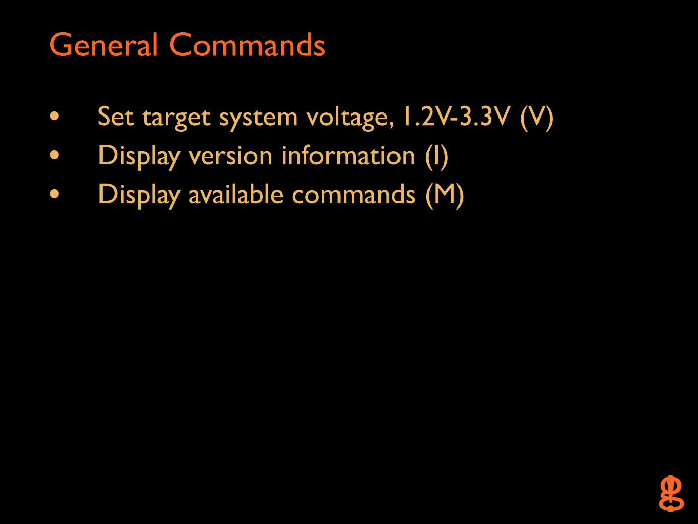
General Commands
• Set target system voltage, 1.2V-3.3V (V)
• Display version information (I)
• Display available commands (M)
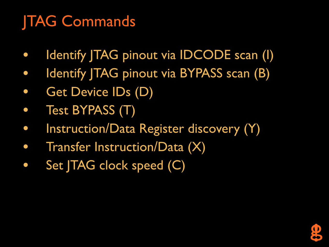
JTAG Commands
• Identify JTAG pinout via IDCODE scan (I)
• Identify JTAG pinout via BYPASS scan (B)
• Get Device IDs (D) • Test BYPASS (T)
• Instruction/Data Register discovery (Y)
• Transfer Instruction/Data (X)
• Set JTAG clock speed (C)
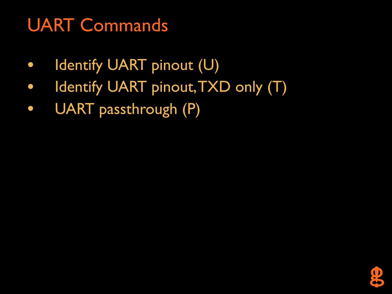
UART Commands
• Identify UART pinout (U)
• Identify UART pinout, TXD only (T)
• UART passthrough (P)
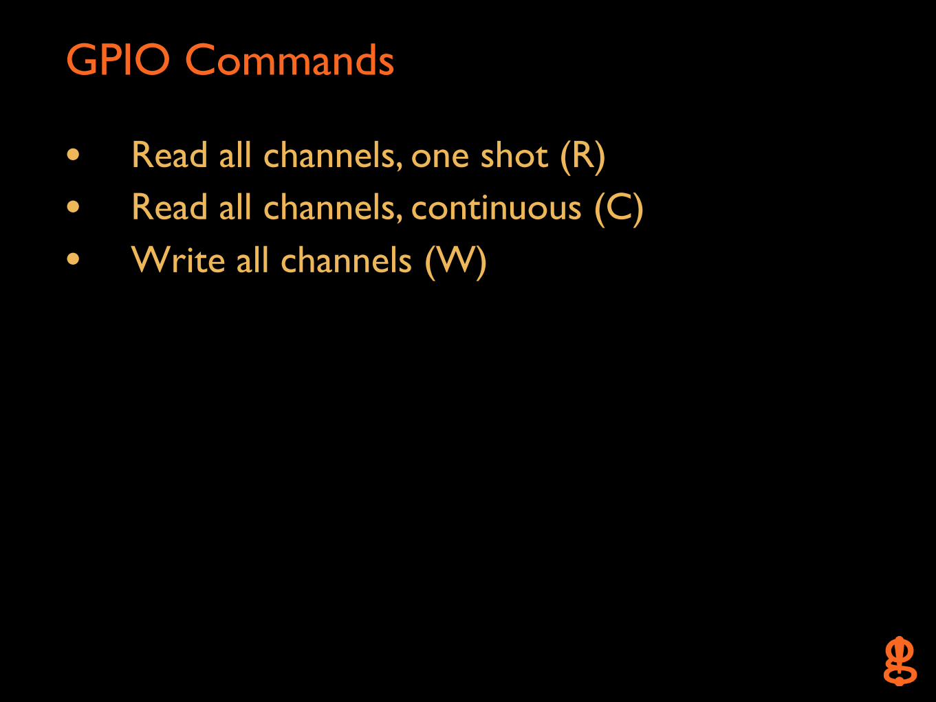
GPIO Commands
• Read all channels, one shot (R)
• Read all channels, continuous (C)
• Write all channels (W)
On-Chip Debug Interfaces
• JTAG
• UART
JTAG
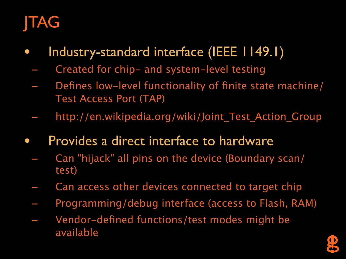
• Industry-standard interface (IEEE 1149.1) - Created for chip- and system-level testing- Defines low-level functionality of finite state machine/
Test Access Port (TAP)
- http://en.wikipedia.org/wiki/Joint_Test_Action_Group
• Provides a direct interface to hardware - Can "hijack" all pins on the device (Boundary scan/
test)- Can access other devices connected to target chip- Programming/debug interface (access to Flash, RAM)- Vendor-defined functions/test modes might be
available
JTAG 2
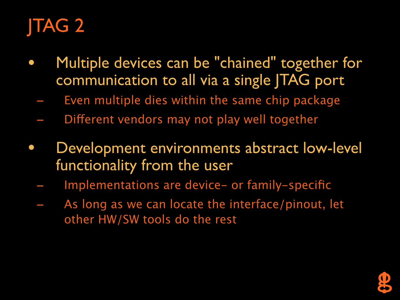
• Multiple devices can be "chained" together for communication to all via a single JTAG port
- Even multiple dies within the same chip package - Different vendors may not play well together
• Development environments abstract low-level functionality from the user
- Implementations are device- or family-specific- As long as we can locate the interface/pinout, let
other HW/SW tools do the rest

JTAG: Architecture
• Synchronous serial interface → TDI = Data In (to target device)← TDO = Data Out (from target device) → TMS = Test Mode Select → TCK = Test Clock → /TRST = Test Reset (optional for async reset)
• Test Access Port (TAP) w/ Shift Registers - Instruction (>= 2 bit wide)- Data
- Bypass (1 bit)- Boundary Scan (variable)- Device ID (32 bit) (optional)
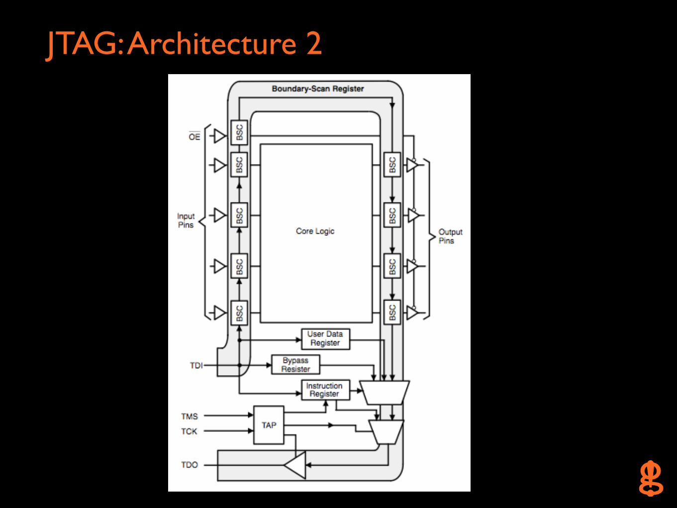
JTAG: Architecture 2
JTAG: Protection
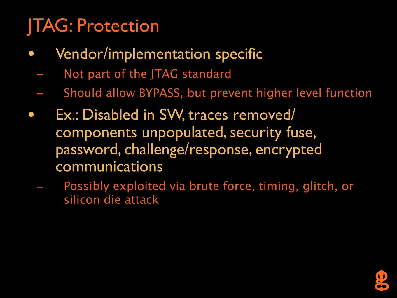
• Vendor/implementation specific - Not part of the JTAG standard- Should allow BYPASS, but prevent higher level function
• Ex.: Disabled in SW, traces removed/components unpopulated, security fuse, password, challenge/response, encrypted communications
- Possibly exploited via brute force, timing, glitch, or silicon die attack
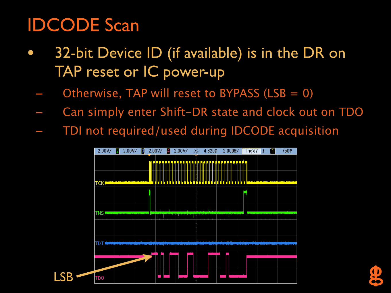
IDCODE Scan
• 32-bit Device ID (if available) is in the DR on TAP reset or IC power-up
- Otherwise, TAP will reset to BYPASS (LSB = 0)- Can simply enter Shift-DR state and clock out on TDO- TDI not required/used during IDCODE acquisition
LSB
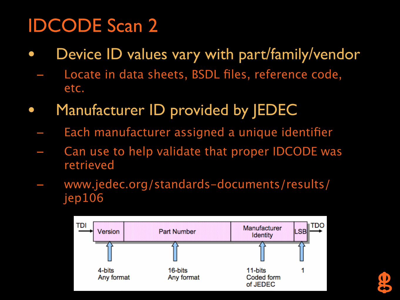
IDCODE Scan 2
• Device ID values vary with part/family/vendor - Locate in data sheets, BSDL files, reference code,
etc.
• Manufacturer ID provided by JEDEC - Each manufacturer assigned a unique identifier - Can use to help validate that proper IDCODE was
retrieved- www.jedec.org/standards-documents/results/
jep106
IDCODE Scan 3
• Ask user for number of channels to use
• For every possible pin permutation (except TDI) - Set unused channels to output high (in case of any
active low reset pins)
- Configure JTAG pins to use on the Propeller- Reset the TAP- Try to get the Device ID by reading the DR- If Device ID is 0xFFFFFFFF or if bit 0 != 1, ignore- Otherwise...
- Display potentially valid JTAG pinout- Try remaining permutations to locate /TRST by
setting each pin low and checking if Device ID can still be retrieved
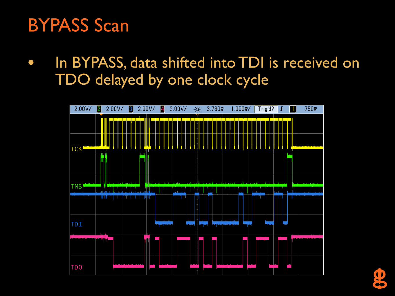
BYPASS Scan
• In BYPASS, data shifted into TDI is received on TDO delayed by one clock cycle
BYPASS Scan 2
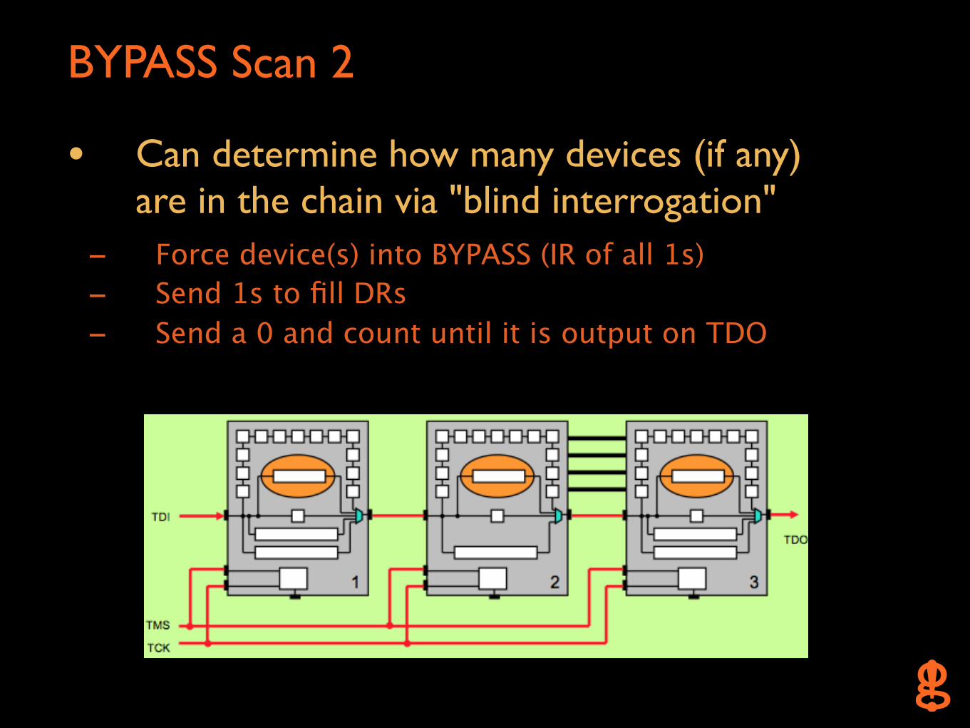
• Can determine how many devices (if any) are in the chain via "blind interrogation"
- Force device(s) into BYPASS (IR of all 1s)- Send 1s to fill DRs- Send a 0 and count until it is output on TDO
BYPASS Scan 3
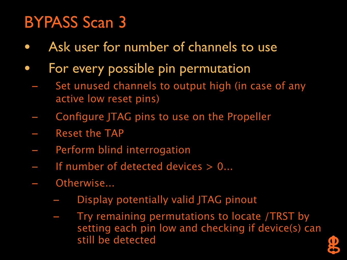
• Ask user for number of channels to use
• For every possible pin permutation - Set unused channels to output high (in case of any
active low reset pins)
- Configure JTAG pins to use on the Propeller- Reset the TAP- Perform blind interrogation- If number of detected devices > 0...- Otherwise...
- Display potentially valid JTAG pinout- Try remaining permutations to locate /TRST by
setting each pin low and checking if device(s) can still be detected
UART
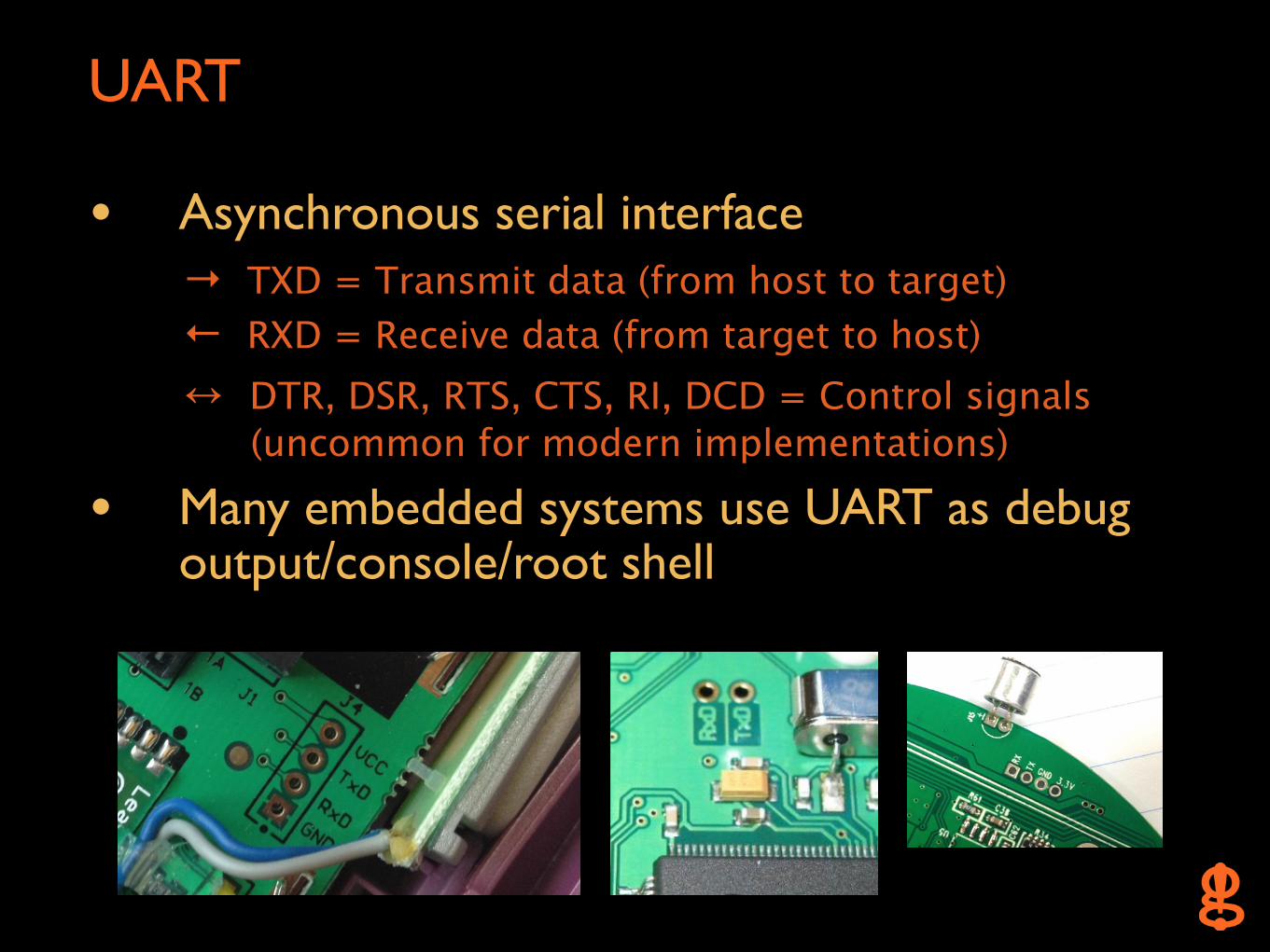
• Asynchronous serial interface → TXD = Transmit data (from host to target)← RXD = Receive data (from target to host)↔ DTR, DSR, RTS, CTS, RI, DCD = Control signals (uncommon for modern implementations)
• Many embedded systems use UART as debug output/console/root shell
UART 2
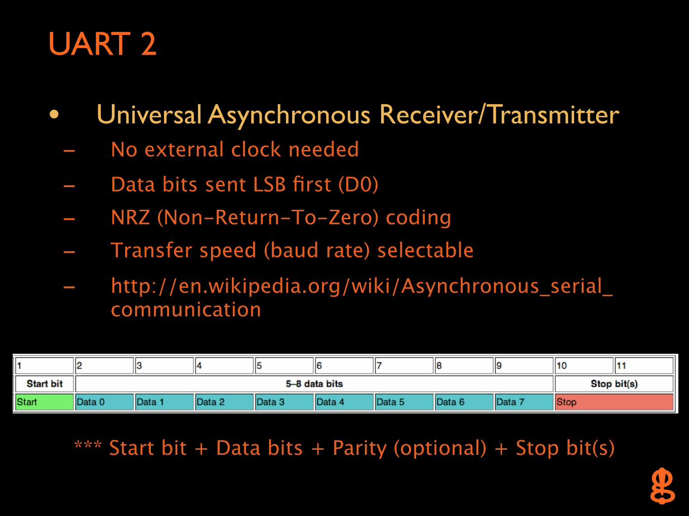
• Universal Asynchronous Receiver/Transmitter - No external clock needed
- Data bits sent LSB first (D0)- NRZ (Non-Return-To-Zero) coding- Transfer speed (baud rate) selectable
- http://en.wikipedia.org/wiki/Asynchronous_serial_ communication
*** Start bit + Data bits + Parity (optional) + Stop bit(s)
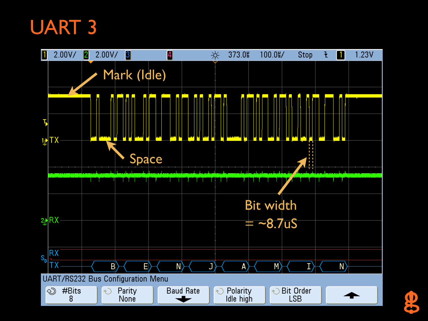
UART 3
Bit width = ~8.7uS
Mark (Idle)
Space
UART Scan
• 8 data bits, no parity, 1 stop bit (8N1)
• Baud rates stored in look-up table - 300, 600, 1200, 1800, 2400, 3600, 4800, 7200,
9600, 14400, 19200, 28800, 31250, 38400, 57600, 76800, 115200, 153600, 230400, 250000, 307200
UART Scan 2
• Ask user for desired output string (up to 16 bytes or 8 bytes in hex using \x prefix)
• Ask user for number of channels to use
• For every possible pin permutation - Configure UART pins to use on the Propeller
- Set baud rate
- Send user string- Wait to receive data (20ms maximum per byte)- If any bytes received, display potentially valid UART
pinout and data (up to 16 bytes)
Possible Limitations
• No OCD interface exists
• OCD interface is physically disconnected - Cut traces, missing jumpers/0 ohm resistors
• OCD interface isn't being properly enabled - System requires other pin settings- Password protected
• Strong pull resistors on target prevent JTAGulator from setting/receiving proper logic levels
• Could cause target to behave abnormally due to "fuzzing" unknown pins
*** Additional reverse engineering will be necessary
Future Work
• Support for OpenOCD - Would allow direct manipulation of target device
after JTAG pinout detection
• Other interfaces - TI Spy-Bi-Wire, ARM Serial Wire Debug,
Microchip ICSP, Atmel AVR ISP, Freescale BDM, LPC Bus, Flash memory
• Level-shifting module? - Target voltage > 5V for industrial/SCADA
equipment

Get It
• www.jtagulator.com
*** Schematics, source code, BOM, block diagram, Gerber plots, photos, videos, other documentation
• www.parallax.com
*** Assembled units, accessories
• http://oshpark.com/profiles/joegrand
*** Bare boards

A Poem

The End.