Embed Size (px)
Citation preview
0
Hkkjr ljdkj jsy ea=ky;
GOVERNMENT OF INDIA MINISTRY OF RAILWAYS
jsyksa ,oa oSYMksa ds ijkJO; ijh{k.k gsrq fu;ekoyh
MANUAL FOR ULTRASONIC TESTING OF RAILS AND WELDS
la’kksf/kr&2012 Revised&2012
vuqla/kku vfHkdYi ,oa ekud laxBu y[kuÅ&226011
Research Designs & Standards Organisation, Lucknow&226011
Updated with CS No.3 Aug-2016
i
GOVERNMENT OF INDIA MINISTRY OF RAILWAYS
MANUAL FOR ULTRASONIC TESTING OF RAILS AND WELDS
Revised 2012
RESEARCH DESIGNS AND STANDARDS ORGANISATION LUCKNOW – 226 011

ii
PREAMBLE
Ultrasonic testing of rails was introduced over Indian Railways during early 60s. From a humble beginning, this technique has graduated itself to an extent that today it is one of the most powerful tools of preventive maintenance of the permanent way. During the last 40 years of its existence, a large number of testing procedures, specifications, guidelines and criteria have been issued from time to time based on the experience gained. In the meantime, the scope of testing has been extended to Alumino Thermic (AT), Flash Butt (FB), Gas Pressure (GP) welded joint, SEJs and Points and Crossings.
The advent of fracture mechanics concept coupled with state of the art steel making technology has thrown open a new dimension in the periodicity of ultrasonic examination. The rate of crack propagation and fracture toughness characteristics of rails can be experimentally found which determine the critical crack size.
Based on the above knowledge and experience, it was considered necessary to assimilate the entire information on ultrasonic examination of rails and present in the form of a manual so as to guide the ultrasonic personnel in testing, interpretation and decision-making. Accordingly, the first edition of the USFD Manual was prepared and issued during 1998. Subsequently, a revision was issued in 2006 in view of the experience gained in the field of USFD testing and maintenance practices. In the recent part, USFD tesing machines having state of the art digital technology have been introduced on Indian Railways and since use of digital USFD testing machine has been made mandatory on Indian Railways, the USFD Manual also required to be updated so incorporate the sensitivity setting procedure for digital USFD tesing machines and other modifications. This revised edition is therefore prepared incorporating all the amendments and revisions. The provisions made are mandatory for all ultrasonic personnel and supersede all previous instructions in case they happen to be contradictory to the instructions contained in this manual. This revised version of the manual incorporates Correction Slip No. 1 to 9 to USFD Manual (2006).
It is also mentioned here that this manual has been exclusively prepared for manual ultrasonic examination of rails and welds and does not cover test procedures for self Propelled Ultrasonic Rail Testing (SPURT) Car.

iii
LIST OF CHAPTERS
S.No. Description Page No. 1. Rail defects and their codification 2. Ultrasonic testing of rails at manufacturer’s works 3. Ultrasonic rail testing equipment and accessories 4. Calibration, Sensitivity setting, Maintenance of machines and functions of
probes 5. Procedure to be followed by USFD operators for undertaking ultrasonic
testing of rails 6. Need based concept in periodic USFD testing of rails and welds 7. Limitations of ultrasonic flaw detection of rails 8. Procedure for ultrasonic testing of Alumino-thermic welded joints 9. Ultrasonic testing of flash butt and gas pressure welded joints 10. Ultrasonic testing of rails required for fabrication of points & crossings 11. Ultrasonic testing technique of worn out point and splice rail prior to
reconditioning by welding and switch expansion joint 12. Ultrasonic testing of rails by SPURT Car 13. Reporting and analysis of Rail/Weld failure
1
8
9
11
17
19
22
24
32
36
38
43
48
iv
LIST OF ANNEXURES
Annexure No. Description Page No.
Annexure I Sketch showing details of standard test piece for ultrasonic testing of symmetrical rail section
Annexure IA Sketch showing details of standard test piece for ultrasonic testing of asymmetrical rail section
Annexure II A Classification of Rail defects for Need Based concept of USFD
Annexure II B Classification of Weld defects for Need Based concept of USFD
Annexure III Proforma for reporting Rail/ Weld replacement or removal on detection by USFD
Annexure IV Details required for Rail/Weld failure analysis
Annexure V Check list of ultrasonic testing of Rails/Welds)
Annexure VI Master register for defects detected and Rail fractures
Annexure VII Master register for defects detected and Weld fractures
Annexure VIII Inspection of rail tester and work of PWI/ (USFD)
49
50
51
56
59
63
67
69
70
71
v
LIST OF FIGURES Fig no. Description Fig. 1 Arrangements of probes for testing of new rails in steel plants Fig. 2A Area covered by Normal (00 )probe Fig. 2B Area covered by 700 probe Fig. 2C Area covered by 700, 2MHz probe (Testing for AT weld flange) Fig. 2D Area covered by700 probes in various Gauge face corner detection equipment Fig. 3 Sensitivity setting block for 700 2 MHz (Centre,gauge face & Non gauge face) probes for testing of rail. Fig. 4 Standard rail with artificial flaws for checking of performance of rai testers. Fig. 5 Rail without flaw (00) probe Fig. 6 Longitudinal horizontal split in head region (type 112, 212, 00 probe) Fig. 7 Longitudinal Horizontal split in head web junction (type 1321-2321, 00 Probe)
Fig. 8 Vertical longitudinal split in head (type 113, 213, 00 probe) Fig. 9 Side probing of rail head , without flaw Fig.10 Vertical Longitudinal split in head (00 side probing) Fig.11 Vertical longitudinal split in web (type 133, 233, 00 probe) Fig.12 Side probing of rail web without defect Fig.13 Vertical longitudinal split in the web 00 side probing Fig.14 Segregation (00 probe ) Fig.15 Bolt hole without crack (00 probe ). Fig.16 Bolt hole with crack (type 135, 235, 00 probe ) Fig.17 Transverse defect (type 111, 211, 700 2MHz, forward probe). Fig.18 Transverse defect (type 111, 211, 700 2MHz, backward probe). Fig.19 Undetectable star cracks (00 probe) Fig.20(a) Standard AT welded rail piece with artificial flaws for sensitivity setting of
ultrasonic equipment to examine AT welds. Fig.20(b) Standard AT welded rail piece with artificial flaws for sensitivity setting of
ultrasonic equipment to examine 75mm wide gap AT welds. Fig.21(a) Sketch showing the location of flange of rail for ultrasonic testing with 700,
2MHz angle probe. Fig.21(b) Testing of bottom flange of A.T. welds using 700 and 450 Probes. Fig.22(a) Standard AT welding rail test piece(half moon crack) Fig.22(b) Sensitivity setting using 450 tendem probe. Fig.22(c) AT weld testing using 450 tendem probe. Fig.23 Probe positions for testing of half moon crack with 450 probe. Fig.24(a) Position of 450 angle probes and beam path for various flaw locations when
examining the head of G.P & F.B.welds. Fig.24(b) Position of 700 angle probe and beam path for various flaw locations when
examining the web and foot of G.P & F.B.welds Fig.25 Standard test rail piece for testing before manufacturing of points and crossings. Fig.26 (a) Testing procedure for points and splice rails for 1 in 12 crossing BG 52 Kg. Fig.26 (b) Standard test piece (SEJ stock rail). Fig.26 (c) Beam direction of angle probes for sensitivity setting Fig.27 Detail of probes used for testing of rails and welds. Fig.28 Sensitivity setting/Testing with 450 probe using Test Rig (for locations having scabs/wheel burns.)
Fig.29 Sensitivity setting block & ultrasonic scaning of tongue rail of SEJ. (Rail in Plan)
Fig.30 Typical signal pattern of bunch of moving signals for AT welds. Fig.31 to 56 Typical rail defects.
Page no.
73 74 75 76 77 78 79 80 81 82 83 84 85 86 87 88 89 90 91 92 93 94 95
96
97
98 99 100 100 101 102
103
104 105 106 107 108 109 110 111
112-125
1
CHAPTER 1
RAIL DEFECTS AND THEIR CODIFICATION
Rail is the most important and critical component of the permanent way. Most common
cause of rail failure is the fatigue fracture, which is due to imperfections present in the material or due to crack formation during service. Thus successful performance of rails is based on their resistance to crack initiation and crack propagation. It is therefore essential to identify and classify the defects in rails and in turn initiate corrective action. A brief on nature of defects, their causes and classification is presented below. 1.1 Causes of defects: The origin and development of such cracks is due to: 1.1.1 Material defects originating during the manufacturing process such as clusters of non-metallic inclusions, hydrogen flakes, rolling marks, guide marks etc. which may be present in spite of successful non-destructive tests carried out on the rails during quality assurance examination. 1.1.2 Residual stresses induced during manufacture (cooling, rolling, gas pressing and straightening). 1.1.3 Defects due to incorrect handling e.g. plastic deformation, scoring, denting, etc. 1.1.4 Defects associated with faulty welding i.e. gas pores, lack of fusion, inclusions, cracks etc. 1.1.5 Dynamic stresses caused by vertical and lateral loads particularly by vehicles with wheel flats or when the vehicle runs over poorly maintained rail joints etc. 1.1.6 Excessive thermal stresses due to variation in rail temperature beyond specified limits. 1.2 Defect location: In order to study the fractures in rail systematically, they may be divided into the following categories based on their location of occurrence in the rail length: (a) Defects emanating from the rail end or reaching the end of the rail. (b) Defects observed within fish-plated zone. (c) Defects not covered in (a) and (b). 1.2.1 Nature of defects in rails (a) Horizontal crack in head: These cracks run usually parallel to the rail table at a depth of
10-20 mm and may finally split the material layer. Crushing of the railhead may also be observed in the vicinity of the crack. Clusters of non-metallic inclusions and abnormal vertical service stresses are the factors responsible for this defect. USFD can easily detect such flaws.

2
(b) Vertical-longitudinal split in head: These cracks run parallel to the longitudinal axis ofthe rail and are caused by presence of non-metallic inclusions, poor maintenance of jointsand high dynamic stresses. It cannot be easily detected in early stages by USFD due totheir unfavourable orientation.
(c) Horizontal crack at head web junction: Such flaws may lead to rail head separation.Contributory causes are wheel flats, bad fish-plated joint, inclusions and high residualstresses. USFD is sensitive to such defects and can easily detect them.
(d) Horizontal crack at web-foot junction: Such cracks develop both towards head and foot.They are caused by high vertical and lateral dynamic loads, scoring and high residualstresses. USFD can easily detect these flaws.
(e) Vertical longitudinal splitting of the web: It is primarily due to heavy accumulation ofnon-metallic inclusions and wheel flats. USFD conducted from rail top can detect it onlyif the defect is severe and in an advanced stage. Vertical longitudinal defects of minornature are not amenable to USFD examination conducted from rail top. Probing fromrailhead sides can detect such defects for which hand probing may be essential.
(f) Bolt hole crack: Such cracks often run diagonally and may run towards head or the foot.They result from inadequately maintained joints and unchamfered fish boltholes andstress concentration. USFD can easily detect these cracks. Normal probes provideindication as diminished back wall echo.
(g) Transverse fracture without apparent origin: These fractures occur suddenly, especiallyduring winter and may emanate from microscopic flaws (embedded or on surface) andare generally very difficult to detect by USFD. These minute flaws manifest suddenlyunder severe service conditions or when the fracture toughness values are comparativelylow.
(h) Transverse fatigue crack in head: They resemble a kidney in shape in the railhead andUSFD is ideally suited for detecting them. They are generally inclined at the angle of18o-23o and originate at a depth of 15-20 mm below the running surface. Mainlyhydrogen accumulation and non-metallic inclusions cause this defect. These cracks areeasily detected by 70o probe.
When such defects are nearly vertical, they can be detected using additional gain of 10db. Defects lying below scabs/wheel burns can be detected by 45o side probing of rail head.
(i) Horizontal crack at top and bottom fillet radius: These cracks are caused byaccumulation of non-metallic inclusions and high residual stresses introduced at the timeof rail straightening. These are difficult to be detected by USFD.
(j) Vertical – longitudinal crack in foot: Such cracks develop from sharp chamfers on thebottom surface of the rail foot. Cracks occurring in this way are the points of origin oftransverse cracks in the foot.
3
(k) Transverse cracks in rail foot: Due to localised overheating during FB welding,structural changes in the bottom surface of the rail material takes place which result in aminor crack. These cracks under the tensile loading give rise to brittle fracture. Suchdefects are not detectable by USFD. Transverse cracks originated from AT welds in therail foot grow as half moon and are detectable by 45o probe.
1.2.2 Nature of defects in welds: Joining rails by improper welding may introduce a variety of defects on the joints as well as in the heat affected zone (HAZ) e.g. lack of fusion, cracks, porosity, slag inclusion, structural variation, etc. The quality of weld depends to a large extent on the careful execution of the welding operation. USFD testing done by manual rail tester suffers from following deficiencies:
(i) Full cross section of weld is not covered by normal USFD examination using manualtester thereby leaving areas in head and foot, which may have flaws.
(ii) Micro structural variations in the weldment cause attenuation of ultrasonic energy.
Therefore, a separate testing procedure for welds has been developed which is elaboratedin Chapters 8 and 9.
1.2.2.1 Defects in Flash Butt Welds
(a) Transverse cracks: The origin of these cracks is the imperfection in the weldment such aslack of fusion, inclusions, etc. Fracture usually occurs from these imperfections, whichmay be in railhead, web or foot. During the course of its propagation USFD testing isextremely effective.
(b) Horizontal cracks: These cracks develop in the web and propagate both in head and foot.The principal cause is large tensile residual stresses acting in the vertical direction.
1.2.2.2 Defects in Alumino-Thermic (AT) Welds
(a) Transverse crack in head and foot: It is caused by inclusions entrapped during welding,which leads to crack initiation on the foot and its growth in the web region causingfracture. Such cracks can be detected by USFD.
(b) Horizontal cracks in web: These cracks occur in AT welds in which the ends having boltholes have not been removed. The presence of holes result in unfavorable stressdistribution caused due to non-uniform cooling. USFD can easily detect such flaws.
1.3 Codification of rail and weld defects: Information regarding the type and nature of railfailures and their service conditions is primarily obtained through personnel responsible formaintenance of permanent way and it is of utmost importance that they are familiar with thevarious types and nature of rail defects and their possible causes to enable them to report the railfailures accurately. With this objective in view, it is necessary to devise a suitable coding systemfor reporting rail failures.
1.3.1 UIC has adopted an Alphanumeric system of codification of rail failures. In view of its international status and the facility afforded for computerized statistical data analysis, this system has been adopted by Indian Railways for reporting rail failures.

4
The code for reporting rail failures consists of two parts viz first – Alphabetic, consisting of three code letters and second numeric, consisting of three or four digits. 1.3.1.1 First part of the code – Alphabetic
(a) First code letter indicates the type of rail:
O indicates Plain rail X indicates Point & crossing rail
(b) Second code letter which follows the first code letter, indicates the reasons for withdraw
of rail. Thus,
F indicates Fractured rail C indicates Cracked rail D indicates Defective rail other than F&C
(c) Third code letter which follows the second code letter, indicates probable cause of failure
or rail. Thus:
R indicates Cause inherent in rail (attributable to faults in the steel making stage and / or its rolling into rails). S indicates Fault of rolling stock C indicates Excessive corrosion J indicates Badly maintained joint M indicates Other maintenance conditions (Defects which develop due To ineffective maintenance or delayed renewal of rails). D indicates Derailment W indicates Associated with welding defects (through or adjacent Within 100 mm of a welded joint) O indicates Other causes
1.3.1.2 Second part of the code – Numeric : This part of the code consisting of three or four
digits indicates the location of the failure in the rail as well as its characteristics : (a) The first digit indicates the location of rail failure (head, web or foot) (b) The second digit indicates:
(i) The position in the rail section from which failure has started except where failure is associated with welding.
(ii) In case of welding, the second digit indicates the type of welding.
(c) The third digit is interpreted in relation to the first two digits of the code viz :
(i) If failure is due to internal defect (first digit 4 or second digit 1,3 or 5), it shows the direction of the crack or fracture.
(ii) If failure is due to surface defect (second digit 2 or 5), it indicates the nature of defect.
5
(iii) If failure is by damage (first digit 3), it indicates the cause of the damage (detailshave been given in succeeding pages)
(d) The fourth digit gives further details.
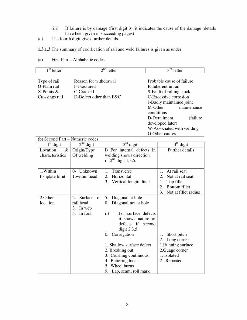
1.3.1.3 The summary of codification of rail and weld failures is given as under:
(a) First Part – Alphabetic codes
1st letter 2nd letter 3rd letter
Type of rail Reason for withdrawal Probable cause of failure O-Plain rail F-Fractured R-Inherent in railX-Points & C-Cracked S-Fault of rolling stockCrossings rail D-Defect other than F&C C-Excessive corrosion
J-Badly maintained jointM-Other maintenance conditionsD-Derailment (failure developed later)W-Associated with weldingO-Other causes
(b) Second Part – Numeric codes1st digit 2nd digit 3rd digit 4th digit
Location & characteristics
Origin/Type Of welding
i) For internal defects inwelding shows direction:if 2nd digit 1,3,5.
Further details
1.Withinfishplate limit
0- Unknown1.within head
1. Transverse2. Horizontal3. Vertical longitudinal
1. At rail seat2. Not at rail seat1. Top fillet2. Bottom fillet3. Not at fillet radius
2.Otherlocation
2. Surface ofrail head3. In web5. In foot
5. Diagonal at hole8. Diagonal not at hole
ii) For surface defectsit shows nature ofdefects if second digit 2,3,5.
0. Corrugation 1. Short pitch2. Long corner
1. Shallow surface defect 1.Running surface2. Breaking out 2.Guage corner3. Crushing continuous 1. Isolated4. Battering local 2 .Repeated5. Wheel burns9. Lap, seam, roll mark
6
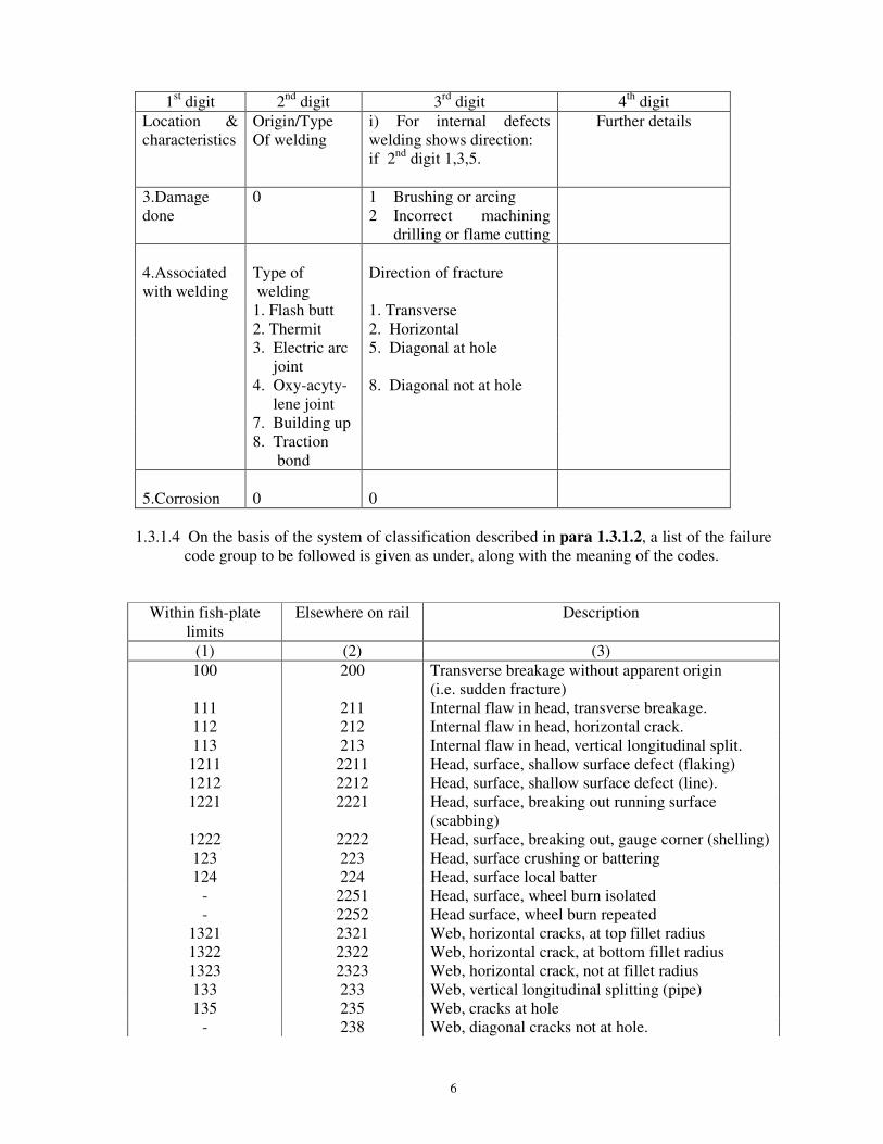
1st digit 2nd digit 3rd digit 4th digit Location & characteristics
Origin/Type Of welding
i) For internal defects welding shows direction: if 2nd digit 1,3,5.
Further details
3.Damage done
0 1 Brushing or arcing 2 Incorrect machining
drilling or flame cutting
4.Associated with welding
Type of welding
Direction of fracture
1. Flash butt 1. Transverse 2. Thermit 2. Horizontal 3. Electric arc
joint 5. Diagonal at hole
4. Oxy-acyty- lene joint
8. Diagonal not at hole
7. Building up 8. Traction
bond
5.Corrosion
0
0
1.3.1.4 On the basis of the system of classification described in para 1.3.1.2, a list of the failure
code group to be followed is given as under, along with the meaning of the codes.
Within fish-plate limits
Elsewhere on rail Description
(1) (2) (3) 100 200 Transverse breakage without apparent origin
(i.e. sudden fracture) 111 211 Internal flaw in head, transverse breakage. 112 212 Internal flaw in head, horizontal crack. 113 213 Internal flaw in head, vertical longitudinal split. 1211 2211 Head, surface, shallow surface defect (flaking) 1212 2212 Head, surface, shallow surface defect (line). 1221 2221 Head, surface, breaking out running surface
(scabbing) 1222 2222 Head, surface, breaking out, gauge corner (shelling) 123 223 Head, surface crushing or battering 124 224 Head, surface local batter
- 2251 Head, surface, wheel burn isolated - 2252 Head surface, wheel burn repeated
1321 2321 Web, horizontal cracks, at top fillet radius 1322 2322 Web, horizontal crack, at bottom fillet radius 1323 2323 Web, horizontal crack, not at fillet radius 133 233 Web, vertical longitudinal splitting (pipe) 135 235 Web, cracks at hole
- 238 Web, diagonal cracks not at hole.
7
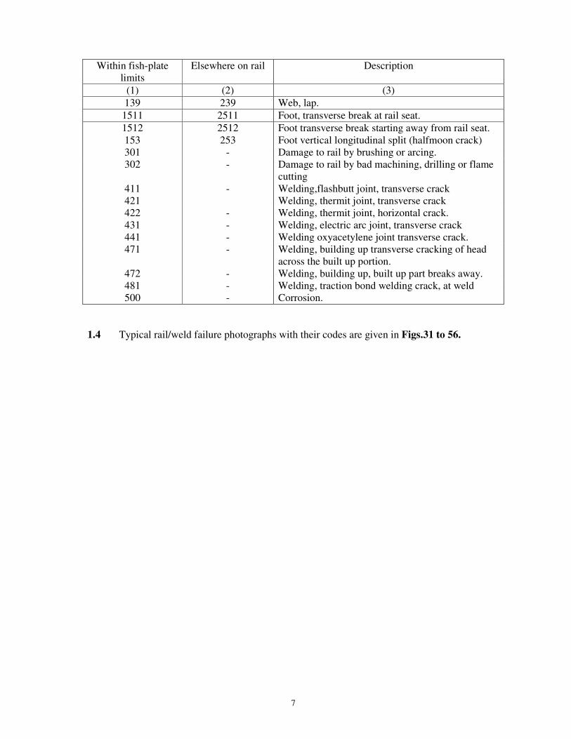
Within fish-plate limits
Elsewhere on rail Description
(1) (2) (3) 139 239 Web, lap. 1511 2511 Foot, transverse break at rail seat. 1512 2512 Foot transverse break starting away from rail seat. 153 253 Foot vertical longitudinal split (halfmoon crack) 301 - Damage to rail by brushing or arcing. 302
411 421
-
-
Damage to rail by bad machining, drilling or flame cutting Welding,flashbutt joint, transverse crack Welding, thermit joint, transverse crack
422 - Welding, thermit joint, horizontal crack. 431 - Welding, electric arc joint, transverse crack 441 - Welding oxyacetylene joint transverse crack. 471 - Welding, building up transverse cracking of head
across the built up portion. 472 - Welding, building up, built up part breaks away. 481 - Welding, traction bond welding crack, at weld 500 - Corrosion.
1.4 Typical rail/weld failure photographs with their codes are given in Figs.31 to 56.
8
CHAPTER 2
ULTRASONIC TESTING OF RAILS AT MANUFACTURERS’ WORKS
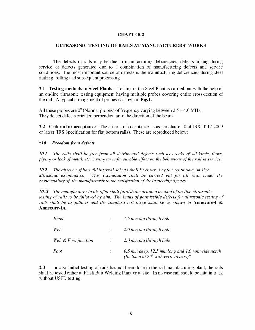
The defects in rails may be due to manufacturing deficiencies, defects arising during service or defects generated due to a combination of manufacturing defects and service conditions. The most important source of defects is the manufacturing deficiencies during steel making, rolling and subsequent processing. 2.1 Testing methods in Steel Plants : Testing in the Steel Plant is carried out with the help of an on-line ultrasonic testing equipment having multiple probes covering entire cross-section of the rail. A typical arrangement of probes is shown in Fig.1.
All these probes are 0o (Normal probes) of frequency varying between 2.5 – 4.0 MHz. They detect defects oriented perpendicular to the direction of the beam.
2.2 Criteria for acceptance : The criteria of acceptance is as per clause 10 of IRS :T-12-2009 or latest (IRS Specification for flat bottom rails). These are reproduced below: “10 Freedom from defects 10.1 The rails shall be free from all detrimental defects such as cracks of all kinds, flaws,
piping or lack of metal, etc. having an unfavourable effect on the behaviour of the rail in service.
10.2 The absence of harmful internal defects shall be ensured by the continuous on-line
ultrasonic examination. This examination shall be carried out for all rails under the
responsibility of the manufacturer to the satisfaction of the inspecting agency.
10..3 The manufacturer in his offer shall furnish the detailed method of on-line ultrasonic
testing of rails to be followed by him. The limits of permissible defects for ultrasonic testing of
rails shall be as follows and the standard test piece shall be as shown in Annexure-I & Annexure-IA.
Head : 1.5 mm dia through hole
Web : 2.0 mm dia through hole
Web & Foot junction : 2.0 mm dia through hole
Foot : 0.5 mm deep, 12.5 mm long and 1.0 mm wide notch
(Inclined at 20o with vertical axis)”
2.3 In case initial testing of rails has not been done in the rail manufacturing plant, the rails shall be tested either at Flash Butt Welding Plant or at site. In no case rail should be laid in track without USFD testing.

9
CHAPTER 3
ULTRASONIC RAIL TESTING EQUIPMENT AND ACCESSORIES 3.0 Ultrasonic testing of rails is a specialized activity and the inspectors carrying out the
ultrasonic testing of rails shall be trained by RDSO, in the techniques of USFD testing. Each Zonal Railway shall create adequate no. of Ex-cadre post of inspectors to ensure that entire track length in their jurisdiction is ultrasonically tested at the laid down periodicity.
When ultrasonic testing of rails and welds is outsourced to a service providing agency, compliance to provisions of latest version of Indian Railway Standard Specification for Ultrasonic Testing of Rails (Provisional) with correction slips issued up to date shall be ensured.
3.1 On Indian Railways, flaw detection by ultrasonics is carried out with the help of two
different types of equipments viz. Single rail tester and double rail tester. The single rail tester has been utilised on Indian Railways for over 40 years and the double rail tester is of a relatively recent origin (developed Ten years back). In addition hand testers of some designs are also being used. Current list of RDSO approved sources for ultrasonic rail/weld testers with their respective models, is contained in latest version of ‘Masters list of approved venders’ circulated bi- annually by Quality Assurance (Mechanical) Directorate of RDSO. Procurement of USFD equipments should be done only from the RDSO approved sources.
3.1.1 Total Life of USFD machine is approximately 8 years. 3.1.2 Maintenance spares be procured along with the machine and should be as per para 4.4
pertaining to maintenance spares. 3.2 Single rail tester : Single rail tester is capable of testing only one of the rails at a time
and is provided with seven probes i.e. 0o , 70o Center Forward (C F), 70o Center Backward (C B), 70o Gauge Face Forward (GF), 70o Gauge Face Backward (GB), 70o Non-gauge face Forward (NGF) and 70o Non-gauge Face Backward (NGB). The normal probe (0o) is utilised for the purpose of detecting horizontal defects situated in head, web or foot. The 70o probe has been specifically provided for detecting defects in the rail head, the most typical of which is the transverse fissure or kidney fracture. The approximate coverage of the rail section with the help of the above arrangement is indicated in Fig.2A & 2D. However, this coverage area does not indicate that detect ability of same size of transverse defect whose nuclei lies within this area at different places will be displayed in same manner. It will depend upon the size, orientation and depth of the defect.
The signal received from the defects by any of the above probes is indicated on the screen. In order to find out the origin of detection i.e. which probe has picked up the defect, provision for displaying the individual probe operation along with audio alarm/LED display has been made in the equipment.
3.3 Double Rail tester:
3.3.1 The double rail tester is capable of testing both the rails at a time. For each rail, seven probes have been provided for the present i.e. 0o, 70o Center Forward (C F), 70o Center Backward (C B), 70o Gauge Face Forward (G F), 70o Gauge Face Backward (G B), 70o Non-gauge face Forward (NGF) and 70o Non-gauge Face Backward (NGB).

10
The signal received from the defects by any of the probes is indicated on the screen. In order to find out the origin of detection i.e. which probe has picked up the defect, provision for displaying the individual probe operation along with audio alarm/LED display has been made in the equipment.
3.3.2 The normal probe is provided for detection of horizontal defects and 70o probes have been
provided for transverse defects in the head. For detection of bolt hole defects, the equipment works on the principle of backwall drop, which in the event of a bolt hole crack shows reduction in echo-amplitude of the backwall. It is also supported by separate audio alarm with distinctly different tone and LED display.
3.3.3 The introduction of double rail tester has been specifically made for enhancing the
productivity of testing and as well as improving the quality and accuracy of flaw detection. Due to pre-calibrated arrangement, frequent setting of the equipment is not considered necessary.
3.3.4 Due to frequent misalignment of probes on the fishplated joints and limitations of
detection of bolt hole cracks having unfavourable orientation and size, it is desirable to deploy double rail testers on LWR/CWR sections. It is desirable to deploy only the ‘single rail tester’ ultrasonic testing machine for testing of sections other than LWR/CWR.
3.4 Specification of rail testers 3.4.1 The single and double rail testers shall be procured to RDSO specification. The
responsibility of inspection for these equipment rests with Director General, RDSO. 3.5 Types of probes: Following types of probes other than mentioned in para 3.2 and
3.3 are also in use. Details of probes and their uses are given at Fig. 27.
450 , 2MHz probe For testing Gas Pressure, Flashbutt Welded rail joints and half Moon Defect in AT Welds below web foot
junction and SEJ. Tandem Scanning ( 2 Nos. of 450 probes in a rig) for
detection of lack of fusion in AT welded rail joints. 70o, 2MHz probe20mm circular Flange & Head testing of AT welds (or 20mm x 20mm square crystal)
700,2MHz Side looking probe Half Moon defect in AT welds below web foot (SLP) junction. 3.6 Test rig for wheel burnt/scabbed rails: For detection of transverse flaws in rail head when rail top surface is having wheel burns/scabs, a test rig with two 450 probes sending beam inward shall be used as shown in Fig. 28. The distance between probe index marks in the rig shall be adjustable and kept as 134mm and 145mm for 52Kg and 60Kg rails respectively while testing. For other rail sections this distance can be computed by multiplying rail head width at 20mm from rail top by 2.
3.7 Tandem rig for AT weld testing : For detection of vertically oriented defects in AT welds like lack of fusion, a tandem test rig
with two 45o probes shall be used as shown in Fig. 22 (b) and (c).

11
CHAPTER-4
CALIBRATION, SENSITIVITY SETTING, MAINTENANCE OF MACHINES AND FUNCTIONS OF PROBES
4.1 Rail testing by ultrasonic method shall be carried out by RDSO approved single rail testing trolley or double rail testing trolley and rig for 45o probes. Details of frequency and number of each type of probes are as under:
Type Frequency No. of probes Single Rail Tester Double Rail Tester Rig
Normal/0o 4MHz One One for each rail - 70o (Center) 2MHz Two(F+B) Two(F+B) for each -
rail. 70o(Gauge Face) 2MHz Two(F+B) Two(F+B) for each -
rail 70o(Non-gauge Face) 2MHz Two(F+B) Two(F+B) for each -
rail 45o (Rig testing) 2MHz - - Two
Water is used as couplant while testing with Single Rail Testers/Double Rail Testers. This is supplied through a water container attached with the trolley. Soft grease to RDSO Specification No.WD-17-MISC.-92 or WD-24 Misc.-2004/ any thick oil of high viscosity grade (having viscosity grade of 150 cst or more) is to be used as couplant while undertaking hand probing of AT welds and deploying 45o probes with test rig for testing rail at scabbed/ wheel burnt locations. The list of approved vendors for soft grease to above mentioned specification is issued by Quality Assurance (Mechanical) Directorate of RDSO bi-annually. The same is available on website of RDSO www.rdso.indianrailways.gov.in.
4.1.1 The procedure laid down for ultrasonic testing of rails is broadly divided in the following steps:
a) Visual inspection of Equipments and accessoriesb) Calibration of equipmentc) Sensitivity setting of the equipment and probesd) Checking of the equipment characteristicse) Testing and interpretation
a) Visual inspection of Equipments and accessories - Daily check
Ultrasonic equipment is to be inspected daily before start of work as per para 5.1.1.
b) Calibration of Digital USFD: The range calibration in digital SRT/DRT withmultiplexure/ multichannel unit is to be undertaken as follows:
I Calibration for 300 / 200 mm longitudinal wave using 0˚ Double Crystal probe
i. Connect the 0˚ / 4 MHz Double Crystal probe to requisite channel given in multiplexureor in the unit itself.

12
ii. Select Mode T-R i.e. Double Crystal/ Multichannel mode in Rail Tester havingmultiplexure. For multichannel unit, select the calibration set which is required tocalibrate.
iii. Feed the required range i.e 300 mm for rail tester having multiplexure/ 200 mm formultichannel rail tester.
iv. Put 0˚ Double Crystal probe on IIW (V1) Block after applying couplant at 100 mmwidth side.
v. Set Delay and Probe Zero ( in unit having multiplexure ) as per operational manual.vi. Set first reflected peak at 3.3 div ( if range is selected 300 mm ) or at 5.0 ( if range is
selected 200 mm ) using delay key provided in multiplexure or DELAY parameterprovided in multichannel unit. Place Gate over it . Press measure 0 ( in unit havingmultiplexure ) and read the beam path, depth shall be 100 mm.
vii. Second reflected peak will appear at 6.7 & third peak at 10.0 ( if range is selected 300mm ) or second peak at 10.0 ( if range is selected 200 mm ) .
viii. If last peak is not at 10.0, velocity may be adjusted to set the last peak at 10.0 ( ifvelocity control available) or by delay key on multiplexure.
ix. The equipment is calibrated for 300 /200 mm Longitudinal wave for 0˚ Double Crystalprobe.
x. To verify the calibration put probe on top of rail head, the back peak position will be at5.2 for 52 Kg. rail & at 5.7 for 60 Kg. rail ( if range is selected 300 mm ) or at 7.8 for52 Kg. rail & at 8.6 for 60 Kg. rail ( if range is selected 200 mm ).
IIIIIIII 165 mm Direct Shear wave calibration for 70165 mm Direct Shear wave calibration for 70165 mm Direct Shear wave calibration for 70165 mm Direct Shear wave calibration for 70˚ / 2 MHz single Crystal Probe
i. Connect the 70˚ / 2 MHz Single Crystal probe to requisite channel given inmultiplexure or in the multichannel unit itself.
ii. Select Mode T-R i.e. Double Crystal mode for rail tester having multiplexure. Formultichannel equipment, select the calibration set and channel required tocalibrate.
iii. Feed range 300 mm for rail tester having multiplexure or 165 mm SW formultichannel unit.
iv. Set Delay and Probe Zero ( in unit having multiplexure ) as per operational manualv. Put 70˚/2 MHz Single Crystal probe on IIW (V1) Block after applying couplant and
direct the beam towards 100 mm curvature.vi. Move the probe slightly to and fro to get maximize signal.vii. Adjust the peak at 6.0 using delay key provided in multiplexure or DELAY
parameter provided in multichannel unit.viii. Place the gate over this peak, press measure 70 ( in unit having multiplexure ) and
read the beam path it shall be 100 mm.ix. To verify the calibration, Direct the probe towards 25 mm curvature and maximize
the peak.x. Put the gate on this peak, the beam path shall be 25 mm.xi. The equipment is calibrated for 165 mm shear wave.
c) Sensitivity setting of the equipment and probes– Check once every 3 days CS No.3
The sensitivity of the USFD equipment shall be set up once in every 3 days(CS No.3) with the help of standard rail pieces as mentioned below:
Sensitivity (gain) setting: For the sensitivity setting of ultrasonic equipment and the probes, the following sequence is to be maintained:
13
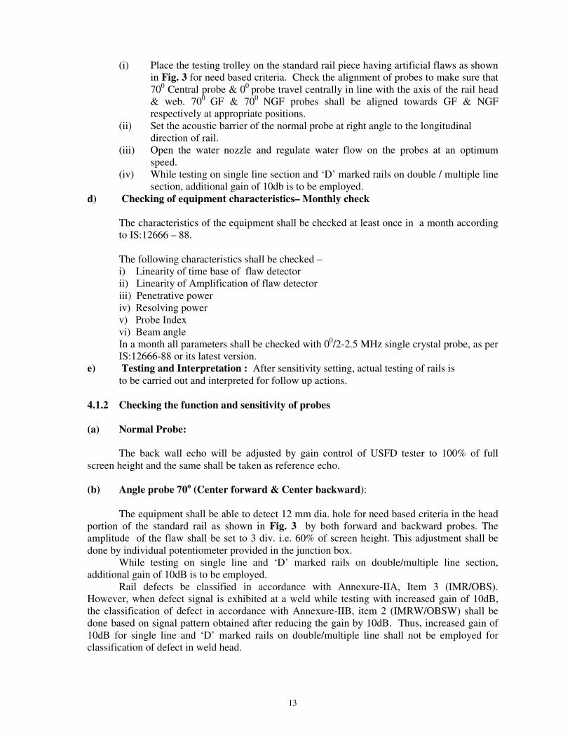
(i) Place the testing trolley on the standard rail piece having artificial flaws as shownin Fig. 3 for need based criteria. Check the alignment of probes to make sure that700 Central probe & 00 probe travel centrally in line with the axis of the rail head& web. 700 GF & 700 NGF probes shall be aligned towards GF & NGFrespectively at appropriate positions.
(ii) Set the acoustic barrier of the normal probe at right angle to the longitudinaldirection of rail.
(iii) Open the water nozzle and regulate water flow on the probes at an optimumspeed.
(iv) While testing on single line section and ‘D’ marked rails on double / multiple linesection, additional gain of 10db is to be employed.
d) Checking of equipment characteristics– Monthly check
The characteristics of the equipment shall be checked at least once in a month according to IS:12666 – 88.
The following characteristics shall be checked – i) Linearity of time base of flaw detectorii) Linearity of Amplification of flaw detectoriii) Penetrative poweriv) Resolving powerv) Probe Indexvi) Beam angleIn a month all parameters shall be checked with 00/2-2.5 MHz single crystal probe, as perIS:12666-88 or its latest version.
e) Testing and Interpretation : After sensitivity setting, actual testing of rails isto be carried out and interpreted for follow up actions.
4.1.2 Checking the function and sensitivity of probes
(a) Normal Probe:
The back wall echo will be adjusted by gain control of USFD tester to 100% of full screen height and the same shall be taken as reference echo.
(b) Angle probe 70o (Center forward & Center backward):
The equipment shall be able to detect 12 mm dia. hole for need based criteria in the head portion of the standard rail as shown in Fig. 3 by both forward and backward probes. The amplitude of the flaw shall be set to 3 div. i.e. 60% of screen height. This adjustment shall be done by individual potentiometer provided in the junction box.
While testing on single line and ‘D’ marked rails on double/multiple line section, additional gain of 10dB is to be employed.
Rail defects be classified in accordance with Annexure-IIA, Item 3 (IMR/OBS). However, when defect signal is exhibited at a weld while testing with increased gain of 10dB, the classification of defect in accordance with Annexure-IIB, item 2 (IMRW/OBSW) shall be done based on signal pattern obtained after reducing the gain by 10dB. Thus, increased gain of 10dB for single line and ‘D’ marked rails on double/multiple line shall not be employed for classification of defect in weld head.

14
(c) Gauge Face and Non-gauge Face Corner probe 70o (Forward and backward):
The trolley is moved on the standard test piece having 5mm Flat Bottom Hole (FBH)made by use of suitable machine (e.g. Electric Discharge Machine) ensuring truly flat surface on bottom of the hole as shown in Fig. 3. The beam of 70o forward gauge face and non-gauge face corner probe is directed to 5mm FBH in rail head. Signals from rail end surface and 5mm FBH will appear on the screen. Move the trolley forward and backward very slowly to get the maximum signal amplitude from the 5mm FBH and adjust the gain to get 60% of full height. Same procedure shall be adopted for 700 backward gauge face and non-gauge face corner probe also.
d) 45o probe (for locations having scabs/wheel burns):
Machine shall be calibrated for 165 mm range for shear wave in the same manner as perprocedure given at para no. 4.1.1 b) II on the rail of same sectional weight under test. Thetest rig shall be placed at 20 mm below rail table on the side of rail head. The transmitter andreceiver probe in the test rig shall be in opposite direction and shall be apart twice the railhead width. Peak obtained in receiver probe shall be adjusted to full scale height by gainsetting. Testing of rails shall be done by keeping index mark of probe 20mm below railtable. Testing frequency and classification of defects shall be as per provisions of Para6.6.1.1 and 6.3 respectively. Note: For 52Kg and 60Kg rails the peak of received signalshall appear at approximately 95mm (shear wave) and approximately 103mm (shear wave)respectively.
Note : Procedure to be followed for adjustment in sensitivity setting on account of variation in rail temperature:
Following procedure shall be used for adjustments in sensitivity setting of Ultrasonic Rail tester on account of variation in rail temperature before starting the testing of rails.
(a) Switch on the Ultrasonic rail tester and keep the equipment for two minutes for thermalacclimatization of the component of the equipment before starting the adjustment insensitivity setting operation.
(b) In the Morning at 8.00hrs.
(i) Normal Probe: Set the sensitivity of the equipment as per Para 4.1.2(a) and notethe gain required to setup the amplitude of the signal to 60% of full screen height.
(ii) Angle probe 70 degree (Forward and Backward): Set the sensitivity of theequipment as per Para 4.1.2(b) and note the gain required to set up the amplitude ofthe signal to 60% of full screen height.
(iii)Angle Probe 37 degree (Forward & Backward): Set the sensitivity of theequipment as per Para 4.1.2(c) and note the gain required to set up the amplitude ofthe signal to 60% of full screen height.
(iv) Note the rail temperature.

15
(c) After setting the sensitivity of the probes, the ultrasonic rail tester shall be retained on thestandard rail test piece in ON condition and the signal amplitude of individual probe
set as per above procedure shall be checked on hourly basis. If the drop in thesignal is observed then the drop shall be compensated by applying extra gain with use ofgain control (dB). The height of signal amplitude is maintained to 60% of full screenheight. Note the change in rail temperature from rail temperature at 8.00 Hrs. andcorresponding extra gain used.
(d) Actual Testing: During actual testing on the track, the gain set by the above procedureshall be maintained depending upon the time and rail temperature during testing. Anyvariation in the signal amplitude shall be compensated by giving measured extra gain(dB) as per step (c) above to carry out ultrasonic testing.
(e) Periodicity of setting the sensitivity: The above procedure for sensitivity calibrationagainst temperature variation shall be carried out at least once in a month. Theadjustments in sensitivity setting of ultrasonic equipment in respect of gain (dB) shall beemployed accordingly.
4.2 Machine Maintenance- Repairs and Half yearly Schedule
Maintenance: The manufacturer shall guarantee the satisfactory performance of the entire rail tester system for a period of one year from the date of commissioning of the equipment by the supplier.
For proper maintenance after expiry of the guarantee period, railway should make proper arrangements for half yearly repairs of electronic and mechanical parts either under AMC with the manufacturer of the equipment or may develop suitable departmental facilities.
Each Zonal railway should create centralised depots for carrying out mechanical repairs and checking the Characteristics of the equipment etc., at least, once in a month.
4.3 Sectional AEN should spent at least few hours (min. two hours) each month during his routine trolley inspection with USFD team and cross check the working including accuracy/ sitting/calibration of USFD machines. In addition, the SE and SSE (in-charge) should also associate themselves occasionally.
4.3.1 The officer having technical control over the SE/JE (USFD) shall exercise regular checks as per Annexure-VIII of USFD Manual once in between two successive half yearly maintenance schedule carried out in the maintenance depots.
4.4 Spares: The recommended spares for normal maintenance of the equipment are given below:
Sl. No. Item Number 1. 00 , 4MHz Double crystal probe 8 Nos.
2 00 2MHz Double crystal probe 4 Nos.
3 700 (F&B) Probe 2 MHz Single crystal 8Nos. 4 450 2 MHz Single crystal probe 2 Nos. 5 700 2MHz Single Crystal Probe 6 Nos. 6 700 2 MHz single crystal probe SLP 2 Nos.
16
7 Connecting Cable (Flaw Detector. with junction box) 6 Nos. 8 BNC connector 6 Nos. 9 00 2/ 2.5 MHz Single Crystal Probe 2 No.
10 Battery charger 1 no. 11 IIW Block (as per IS: 4904) 2 per depot 12 60x50x50 mm steel block ( as per steel grade 45C8 to
IS:1875-1992) 1 No.
13 Fuse 12 Nos. 14 Step gauge 1 No.
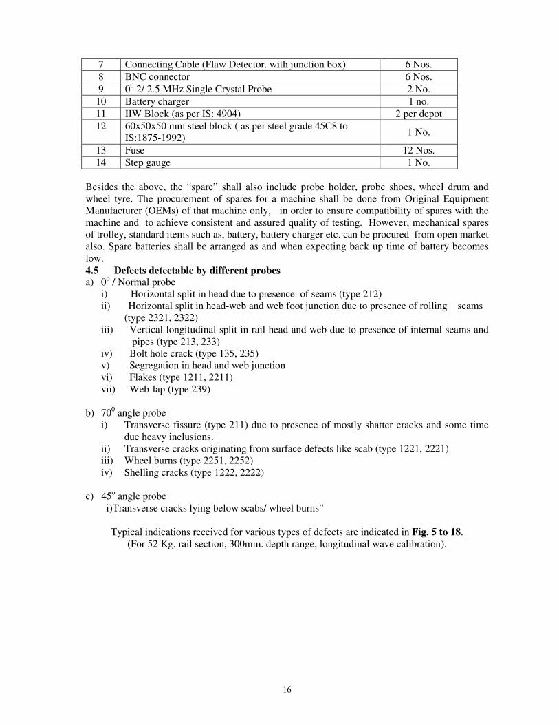
Besides the above, the “spare” shall also include probe holder, probe shoes, wheel drum and wheel tyre. The procurement of spares for a machine shall be done from Original Equipment Manufacturer (OEMs) of that machine only, in order to ensure compatibility of spares with the machine and to achieve consistent and assured quality of testing. However, mechanical spares of trolley, standard items such as, battery, battery charger etc. can be procured from open market also. Spare batteries shall be arranged as and when expecting back up time of battery becomes low. 4.5 Defects detectable by different probes a) 0o / Normal probe
i) Horizontal split in head due to presence of seams (type 212)ii) Horizontal split in head-web and web foot junction due to presence of rolling seams
(type 2321, 2322)iii) Vertical longitudinal split in rail head and web due to presence of internal seams and
pipes (type 213, 233)iv) Bolt hole crack (type 135, 235)v) Segregation in head and web junctionvi) Flakes (type 1211, 2211)vii) Web-lap (type 239)
b) 700 angle probei) Transverse fissure (type 211) due to presence of mostly shatter cracks and some time
due heavy inclusions.ii) Transverse cracks originating from surface defects like scab (type 1221, 2221)iii) Wheel burns (type 2251, 2252)iv) Shelling cracks (type 1222, 2222)
c) 45o angle probei)Transverse cracks lying below scabs/ wheel burns”
Typical indications received for various types of defects are indicated in Fig. 5 to 18. (For 52 Kg. rail section, 300mm. depth range, longitudinal wave calibration).
17
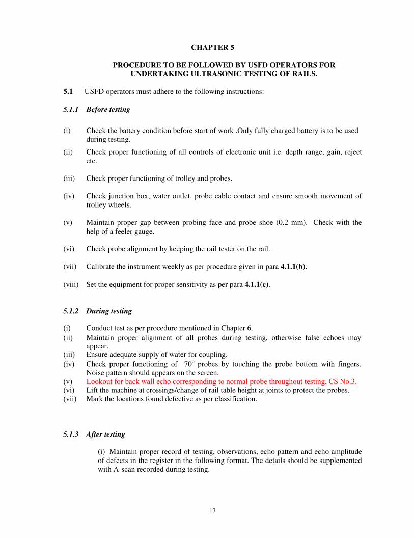
CHAPTER 5
PROCEDURE TO BE FOLLOWED BY USFD OPERATORS FOR UNDERTAKING ULTRASONIC TESTING OF RAILS.
5.1 USFD operators must adhere to the following instructions:
5.1.1 Before testing
(i) Check the battery condition before start of work .Only fully charged battery is to be usedduring testing.
(ii) Check proper functioning of all controls of electronic unit i.e. depth range, gain, rejectetc.
(iii) Check proper functioning of trolley and probes.
(iv) Check junction box, water outlet, probe cable contact and ensure smooth movement oftrolley wheels.
(v) Maintain proper gap between probing face and probe shoe (0.2 mm). Check with thehelp of a feeler gauge.
(vi) Check probe alignment by keeping the rail tester on the rail.
(vii) Calibrate the instrument weekly as per procedure given in para 4.1.1(b).
(viii) Set the equipment for proper sensitivity as per para 4.1.1(c).
5.1.2 During testing
(i) Conduct test as per procedure mentioned in Chapter 6.
(ii) Maintain proper alignment of all probes during testing, otherwise false echoes mayappear.
(iii) Ensure adequate supply of water for coupling.
(iv) Check proper functioning of 70o probes by touching the probe bottom with fingers.Noise pattern should appears on the screen.
(v) Lookout for back wall echo corresponding to normal probe throughout testing. CS No.3.(vi) Lift the machine at crossings/change of rail table height at joints to protect the probes.(vii) Mark the locations found defective as per classification.
5.1.3 After testing
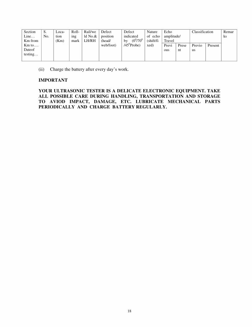
(i) Maintain proper record of testing, observations, echo pattern and echo amplitudeof defects in the register in the following format. The details should be supplementedwith A-scan recorded during testing.
18
(ii) Charge the battery after every day’s work.
IMPORTANT
YOUR ULTRASONIC TESTER IS A DELICATE ELECTRONIC EQUIPMENT. TAKE ALL POSSIBLE CARE DURING HANDLING, TRANSPORTATION AND STORAGE TO AVIOD IMPACT, DAMAGE, ETC. LUBRICATE MECHANICAL PARTS PERIODICALLY AND CHARGE BATTERY REGULARLY.
Section Line… Km from Km to…. Dateof testing…
S. No.
Loca-tion (Km)
Roll-ing mark
Rail/weld No.& LH/RH
Defect position (head/ web/foot)
Defect indicated by (00/700
/450Probe)
Nature of echo (shift/fixed)
Echo amplitude/ Travel
Classification Remarks
Previous
Present
Previous
Present

19
CHAPTER 6
NEED BASED CONCEPT IN PERIODIC USFD TESTING OF RAILS AND WELDS
6.1 Introduction: Safety against failures of rails in track depends upon the inspection frequency and the permissible defect size, other factors like rail metallurgy and loading conditions remaining same. To extract maximum service life out of the rails while ensuring safety, the inspection frequency has to be increased so that the rails are allowed to remain in track for longest possible period. At the same time, frequent watch over increasing incidence of defects is necessary. However, very high frequency of inspection as a general measure is not always practicable as cost of inspection becomes prohibitive.
The optimum cost of maintaining rails in track can, therefore be achieved if the inspection frequency is made dependent on the incidence of the defects. In such a concept of need based inspection, on sections where the number of defects detected is low, the inspection frequency is also kept low whereas on sections where the number of detected defects is high the inspection frequency also gets increased. The advantages of such a concept are obvious because the inspection resources are not unnecessarily frittered away on sections where the condition of rail is sound and its performance in track does not warrant frequent inspection.
Introduction of Need Based Concept of USFD has necessitated changes in the areas of classification of defects, frequency of inspection, detection equipment, organization, etc. In the following paragraphs these aspects are discussed.
6.2 Basis of change in criteria for defect classification: The inspection frequency and condemning defect sizes are related parameters. If the inspection frequency is high, the condemning defect size can be suitably increased. Increase in condemning defect size also enhances the reliability of inspection, as chances of non-detection for smaller size defects are high. In the existing criteria which was evolved more than 25 years back, the condemning defects size, especially for OBS defects was kept very small. Now with 25 years of experience behind us in the area of USFD testing of rails and also the findings of studies in crack propagation mechanism conducted at RDSO, a more rational condemning defects size has now been specified. As a result, in the revised criteria to be used for need based USFD inspection, only IMR and OBS categories exist. The effect of this revision is to rationalise and suitably raise the condemning defect size in view of the higher frequency specified for inspection.
6.3 Classification of rail defects: Defects detected during through USFD testing of rail shall be classified as per Annexure-II A. However visible defects on rails/ welds shall not be clarified by USFD personal and the same shall be recorded & brought to notice of sectional PWI
for further remedial action. ''6.3. l: Defect at any location which is detected by two or more probes and are considered to be classified as OBS/OBSW based on peak pattern of individual probe, should be classified as IMR/IMRW and action shall be taken accordingly as per Para 6.4.6.3.2: In case two or more OBS/OBSW defects are located within a distance of 4.0 metre from each other, such OBS/OBSW defects shall be classified as IMR/IMRW and action shall be taken accordingly as per Para 6.4." Cs No.3 Aug-2016.

20
6.4 Action to be taken after Detection of defects: Following action shall be taken in respect of defective rails & welds:
S. No.
Classifi-cation
Painting on both faces of web
Action to be taken Interim action
1. IMR IMRW
Three cross with red paint
The flawed portion should be replaced by a sound tested rail piece of not less than 5.5m length (in case of fish plated track) & 4m (in case of welded track) within 3 days of detection.
SE/JE(P.Way)/USFD shall impose speed restriction of 30 Kmph or stricter immediately and to be continued till flawed rail/weld is replaced. He should communicate to sectional SE/JE(P.Way) about the flaw location who shall ensure that clamped joggled fish plate is provided within 24 hrs.
2. OBS OBSW
One cross with red paint
Rail/weld to be provided with clamped joggled fish plate within 3 days. SE/JE(P. Way)/USFD to specifically record the observations of the location in his register in subsequent rounds of testing.
SE/JE(P. Way)/USFD to advise sectional SE/JE(P. Way) within 24 hrs about the flaw location. Keyman to watch during daily patrolling till it is joggled fish plated.
6.5 AT/FB/GP weld defect classification
6.5.1 Defects detected by 00/ 4 MHz double crystal probe & 700/ 2 MHz single crystal probe during through rail testing for defects detected in AT/FB/GP welds shall be classified as per Annexure-II B.
6.6 Frequency of testing of rails and welds: In view of the revised criteria of defect mentioned in Para 6.2 the testing frequency of 8 GMT has been prescribed.
6.6.1 After the initial testing of rails in rail manufacturing plant, the first retesting need not normally be done until the rails have undergone 15% of the service life in GMT as given below (para 302 (i) (d) of IRPWM):
For rails rolled in April 1999 and later, the test free period shall be 25% instead of 15%.
Gauge Rail Section Assessed GMT service life for T.12 72 UTS rails
Assessed GMT service life for T-12 90 UTS rails
B.G. 60Kg 550 800 52Kg 350 525 90 R 250 375
M.G. 75 R 150 - 60 R 125 -

21
Whenever, rails are not tested in rail manufacturing plant, the test free period shall not be applicable and the rail testing shall be done at the periodicity given below right from the day of its laying in field.
However, the rails having sectional weight and grade equal to or higher than 52Kg/90UTS shall be ultrasonically tested covering gauge face and non-gauge face corner of rail head on passage of every 40GMT traffic during test free period.
6.6.1.1 Frequency of testing for all Main line BG (rail head center and gauge face/non-gauge face corner) and MG routes is given as under: For other sections Chief Engineer of the Railway may adopt a frequency at his discretion.” CS-1
Route Routes having GMT Testing frequency Once in
All MG routes < 2.5 5 years
2.5 – 5.0 3 years
> 5 2 years
All BG routes (rail head center and gauge face
corner testing)
< 5 2 years
> 5 < 8 12 months
> 8 < 12 9 months
> 12 < 16 6 months
> 16 < 24 4 months
> 24 < 40 3 months
> 40 < 60 2 months
>60< 80 1½ months
>80 1 month
Digital double Rail Tester is to be used for testing of ‘D’ marked rails at reduced interval to be decided by Chief Track Engineer of Zonal Railway.
6.7 Equipment: RDSO approved rail testing equipment shall be employed for conducting ultrasonic examination. Both single as well as double rail testing equipments are suitable for this purpose.
6.8 Check list of Ultrasonic Testing of Rail/Welds:
A check list for the officials inspecting the quality of work being done by the Inspectors carrying out Ultrasonic Testing of Rails/Welds is placed at Annexure – V.

22
CHAPTER – 7
LIMITATIONS OF ULTRASONIC FLAW DETECTION OF RAILS
7.0 Every scientific method/technique/equipment functions on certain principles and its applicability depends upon fulfillment of preconditions necessary to be satisfied. It accordingly implies that USFD examination is based on certain guiding principles and its flaw detection success depends upon thorough understanding of the governing factors.
Thus, the limitations being mentioned are not per-se the deficiency of the USFD technique rather in the existing arrangement under field conditions the equipment utilised incorporates facility only for specified defects. This aspect may be kept in view and the technique is to be pursued accordingly.
Limitations in respect of rail examination considering the various arrangements presently available have been elaborated below. It may also be mentioned here that limitations with regard to AT welding i.e. defects in web foot junction half moon cracks, vertical defects in web portion etc. are no longer limitations of the USFD equipments since in the newly developed equipment special probes have been provided for detection of these defects.
7.1 (i) To detect the defect efficiently, ultrasonic beam is to be directed towards the flaw perpendicularly, otherwise, the reflected beam may not be received by the receiver crystal, resulting in absence/reduction in amplitude of flaw signal in the CRT. Cracks normally have facets and hence even under misorientation provide reflecting surfaces leading to flaw indication.
(ii) For detection of defects in rails, probes having incidence angle 0o, 70 o (F), 70 o (B) havebeen provided in the USFD trolley. The angles have been choosen in a manner so as todetect defects which are generally observed during service and have been the cause of railfractures.The section of rail which is scanned by each type of probe has been indicated in Fig.2A, 2B, 2C and 2D.
For detection of defects originating from Gauge Face and Non-gauge Face Corner, adedicated test set-up has been developed. This set-up includes three 70 o probes coveringapprox. the full width of the rail head and a set of two 45 o probes. The area scanned bythis arrangement is shown in Fig.2D. A defect located at 5mm from the corner isdetectable using this equipment
All commonly observed defects in rails are detectable by the above arrangement. In the event of gross mis-orientation of defect at times it may not be amenable for detection, however such situations are rare.
(iii) Severe pipe in the rail may give indication of flaw echo by 0 o probe, But in case ofhairline or fine central shrinkage (pipe), negligible drop occurring in bottom signal mayremain unnoticed by the USFD operator. (Ref Fig. 8 & 11 )
(iv) For detection of bolt hole cracks, 37 o probes are ideal. This is because the cracksemanating from bolt holes are generally oblique and propagate in the zig-zag manner.However, the present SRT/DRT machines have not been provided with 37 o probes due tolimitation of number of channels and detection of bolt hole cracks is accomplished bynormal probe. These cracks are detectable by 0 o probe since they obstruct the path ofsound waves and lead to drop/loss of back wall echo.
23
If the cracks are so located that they are unable to be scanned by 0o probes due to smaller size or orientation, such cracks may not be detected in initial stages of their development.”
(v) If sensitivity of the machine is poor or battery gets discharged the operator may miss theflaw signal. Hence, it is essential to ensure full charging of the battery.
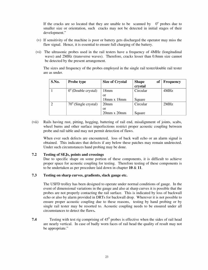
(vi) The ultrasonic probes used in the rail testers have a frequency of 4MHz (longitudinalwave) and 2MHz (transverse waves). Therefore, cracks lesser than 0.8mm size cannotbe detected by the present arrangement.
The sizes and frequency of the probes employed in the single rail tester/double rail testerare as under.
S.No. Probe type Size of Crystal Shape of crystal
Frequency
1 0o (Double crystal) 18mm or 18mm x 18mm
Circular
Square
4MHz
2 70o (Single crystal) 20mm or 20mm x 20mm
Circular
Square
2MHz
(vii) Rails having rust, pitting, hogging, battering of rail end, misalignment of joints, scabs,wheel burns and other surface imperfections restrict proper acoustic coupling betweenprobe and rail table and may not permit detection of flaws.
When ever such defects are encountered, loss of back wall echo or an alarm signal isobtained. This indicates that defects if any below these patches may remain undetected.Under such circumstances hand probing may be done.
7.2 Testing of SEJs, points and crossingsDue to specific shape on some portion of these components, it is difficult to achieveproper space for acoustic coupling for testing. Therefore testing of these components isto be undertaken as per procedure laid down in chapter 10 & 11.
7.3 Testing on sharp curves, gradients, slack gauge etc.
The USFD trolley has been designed to operate under normal conditions of gauge. In the event of dimensional variations in the gauge and also at sharp curves it is possible that the probes are not properly contacting the rail surface. This is indicated by loss of backwall echo or also by alarm provided in DRTs for backwall drop. Wherever it is not possible to ensure proper acoustic coupling due to these reasons, testing by hand probing or by single rail tester may be resorted to. Acoustic coupling needs to be ensured under all circumstances to detect the flaws.
7.4 Testing with test rig comprising of 450 probes is effective when the sides of rail head are nearly vertical. In case of badly worn faces of rail head the quality of result may not be appropriate.”

24
CHAPTER 8
PROCEDURE FOR ULTRASONIC TESTING OF ALUMINO- THERMIC WELDED RAIL JOINTS
8.1 Scope: Following types of testing for Alumino Thermic (AT) welds have been prescribed. These are:
a) Testing of weld head/web, which gets covered during through periodic rail testing by SRT/DRT as per Para 6.6. The frequency of testing in this case is as per Para 6.6.1.1. As per this testing defects detected in weld heads are classified as ‘IMRW’ and ‘OBSW’ vide Annexure II B. The action to be taken for such defective welds is as per Para 6.4.
b) Periodic testing of complete weld by hand probing of weld head/web and bottom flange, using 00 2MHz, 700 2 MHz, 45o 2 MHz probe (AT weld foot scanning for half moon shaped defect) and 700 2 MHz SL probes. The frequency of testing in this case is as per Para 8.15.1. As per this testing defects detected in welds are classified as ‘DFWO/ DFWR’. The action to be taken for such defective welds is as per Para 8.14.
c) Besides this, welds are also tested after their execution using 00 2MHz, 700 2MHz, 45o 2 MHz probe (AT weld foot scanning for clustered defect/ micro porosities in web foot region) and 45o 2 MHz (Tandem probe scanning for lack of fusion). This test is termed as Initial Acceptance Test. As per this testing, defects detected in welds are classified as ‘DFWO/ DFWR’. The action to be taken for such defective welds is as per Para 8.10.”
This Chapter covers the requirement of complete ultrasonic testing of Alumino- thermic welded rail joints by hand probing immediately after execution of the weld described at c) above and for periodic examination of complete weld described at b) above only.
8.2 Apparatus required: 8.2.1 Equipment: Any RDSO approved model of ultrasonic equipment for
Alumino-thermic welded rail joints as per RDSO specification No. M&C/NDT/129/2005 or its latest version along with rig for tandem testing.
8.2.2 Probes: The following probes having Lead zincronate- titanate crystal shall be
used for Ultrasonic testing of Alumino-thermic joints.
a) Normal ( 0° ) 2 MHz, 18 mm. φ Double crystal.
b) 45°/ 2 MHz, 20mm.dia. or 20mm.x20 mm.( square ) crystal size, Single crystal –1 no.
c) 70°/2 MHz, 20mm.dia. or 20mm.x20 mm. ( square )crystal size, Single crystal - 1 no.
d) A pair of two 70°/2 MHz probes inclined at 20o side looking with respect to usual beam path. Side looking angle of both probes shall be in opposite direction to each other
.8.2.3 Cables: Co-axial cable for each probe shall be used .The length shall not be more than 2.0 metre.
8.2.4 Couplant: soft grease/oil shall be used as couplant as per specification given in para 4.1.

25
8.3 General Condition: After execution of AT weld, welded zone shall be dressed properly to facilitate placement of probes and to avoid incidence of spurious signal on the screen. The top of rail head surface shall be dressed to obtain reasonably flat and smoo th surface. The flange of the weld up to a distance of 200 mm. on either side of the weld collar shall be thoroughly cleaned with a wire brush to ensure freedom from dust, dirt, surface unevenness etc.
8.3.1 Visual Examination: All the welded joints shall be cleaned and examined carefully to detect any visible defects like cracks, blow holes. Any joint which shows any visible defect shall be declared defective.
8.4 Sensitivity setting procedure: 8.4.1 Standard test rail: The sensitivity of the ultrasonic equipment shall be set with
the help of a standard AT welded rail piece of 600 mm (300 mm rail each side of joint ) length having a simulated flaw at standard locations as shown in Fig.20 (a). The standared AT welded rail piece shall be preferably of same AT welding technique & welding agency which are to be tested in field to avoid confusion of signals from weld profile.
8.5 0°°°°/2 MHz, Double crystal Normal Probe: This scanning is used to detect Porosity, Blow hole, Slag inclusion in head and up-to mid web of the AT welded joint.
8.5.1 Calibration: Following procedure shall be adopted for calibration of 00 2 MHz double crystal probe
i. Select range 300 mm with range control key.ii. Select Mode T-R i.e. Double Crystal mode.
iii. Set Delay 0.iv. Set Probe Zero 0.v. Feed longitudinal wave velocity (5920 m/s) / Press measure 0 key.
vi. Feed angle 00.vii. Connect 0˚ Double Crystal probe and put it on IIW (V1) Block after applying couplant
at 100 mm width side.viii. Set first reflected peak at 3.3 div. using probe zero. Place Gate over it and read the
beam path, depth shall be 100 mm.ix. Second reflected peak will appear at 6.7 & third peak at 10.0.x. If last peak is not at 10.0, velocity may be adjusted to set the last peak at 10.0 ( if
velocity control available).xi. The equipment is calibrated for 300 /200 mm Longitudinal wave for 0˚ Double Crystal
probe.xii. To verify the calibration, put probe on top of rail head, the back peak position will be at
5.2 for 52 Kg. rail & at 5.7 for 60 Kg. rail.
8.5.2 Sensitivity setting: Place 0°normal probe on test rail. The reflection from 3 mm.dia. hole in head of standard AT welded rail test piece shall be set to 60% offull screen height by suitable manipulation of gain control.
8.5. 3 Test Procedure: The probe shall be placed on the head of the AT welded joint ensuring proper acoustic coupling. The probe shall be moved on the weld centre to scan the weld area.

26
8.5.4 Defect classification:
a) For any flaw signal obtained by normal probe from the head region,i) Flaw signal 40% and above and up to 60% to be declared as DFWO.ii) Flaw signal above 60% to be classified as DFWR.b) For any flaw signal obtained by normal probe from web or foot location,i) Flaw signal of height more than 20% from the web or foot and up to 40% to beclassified as DFWO.ii)Flaw signal of height more than 40% from the web or foot or more to beclassified as DFWR.
8.6 70°°°°/ 2 MHz (Head scanning):This scanning is used to detect lack of fusion, porosity, blow hole, slaginclusion, cracks in head of AT welded joint.
8.6.1 Calibration: Following procedure shall be adopted for calibration of 700 2 MHz single crystal probe:
i. Select range 165 mm with range control key.ii. Select Mode T+R i.e. Single Crystal mode.iii. Set Delay 0.iv. Set Probe Zero 0.v. Feed Shear wave velocity (3230 m/s) / Press measure 70 key.
vi. Feed angle 700.vii. Connect 70˚/2MHz Single Crystal probe and put it on IIW (V1) Block after applying
couplant and direct the beam towards 100 mm curvature.viii. Move the probe slightly to and fro to get maximize signal.ix. Using probe zero set this peak at 6.0 or by using gate read beam path 100 mm.x. To verify the calibration, Direct the probe towards 25 mm curvature and maximize the
peak.xi. Put the gate on this peak, the beam path shall be 25 mm.xii. The equipment is calibrated for 165 mm shear wave.
8.6.2 Sensitivity setting: Connect the 70°°°°/ 2 MHz by means of co- axial cables and select (T+R) mode. Place the probe on the railhead directing the beam towards 3-mm. dia.-drilled hole in the head of the standard AT welded test piece. Move theprobe in longitudinal direction on the rail so that reflection from the hole isobtained. Now set the height of the reflected signal to 60% of full screen heightby suitable manipulation of the gain control . This gain shall be used for testing.
8.6.3 Test procedure: Place the probe on the rail head on one side of the AT welded reinforcement and move toward the weld in zig-zag manner. This exercise shall be repeated 2-3 times. The same shall be carried out from both sides of the weld.
8.6.4 Defect classification: i) A welded joint showing moving signal of 40% or more
and up to 60% of FSH shall be classified as DFWO. ii) A welded joint showing moving signal of more than 60% of full screen height to be classified as DFWR.A bunch of moving signals more than 10% CS No.3 and more than 10% shall also be considered as defective weld & to be declared as DFWR. (Fig. no.30).
8.7 450 / 2MHz probe:
8.7.1 450 / 2MHz probe (AT weld foot scanning):
This scan is used to inspect the clustered defects/ micro porosities and half moon shaped defect at the bottom of weld foot. (Fig. 22 (a))
27
8.7.1.1 Range calibration: Following procedure shall be adopted for calibration of 450 2 MHz single crystal probe
i. Feed range 275 mm with range control key.ii. Select Mode T+R i.e. Single Crystal modeiii. Set Delay 0iv. Set Probe Zero 0v. Feed Shear wave velocity ( 3230 m/s)vi. Feed angle 45˚vii. Connect 45˚/2 MHz Single Crystal probe and put it on IIW (V1) Block after applying
couplant and direct the beam towards 100 mm curvature.viii. Move the probe slightly to and fro to get maximize signal.ix. Using probe zero set this peak at 3.6 or by using gate read beam path 100mm.x. To verify the calibration, Direct the probe towards 25 mm curvature and maximize
the peak.xi. Put the gate on this peak, the beam path shall be 25 mm.xii. The equipment is calibrated for 275 mm shear wave.
8.7.1.2 Sensitivity setting: Place 450 /2MHz probe on the rail head surface at a distance equal to height of rail from the centre of the AT weld.{Fig. 22 (a)}. Select T+R single crystal mode. Move the probe 20mm either side of this position (probe index marking) to pick up half-moon crack in the central region of weld reinforcement as shown in Fig 23. This exercise shall be carried out two- three times from each side of the weld and signal from simulated flaw should appear at a distance of approximately 400mm for 52 kg rail. This distance will vary with respect to rail section height. The signal so obtained shall be adjusted to 60% of full screen height by manipulating the gain control.
8.7.1.3 Test Procedure: The probe (450/2MHz probe /single crystal) shall be placed on the rail head at a distance equal to height of the rail from the centre of AT weld (Probe index marking) under test with same sensitivity as per para 8.7.1.2. This testing technique will scan the bottom of the weld in the central zone. The probe shall be moved 20 mm on either side of the probe index marking. The scanning shall also be repeated from other side of weld with beam directing towards the foot region of the weld.
8.7.1.4 Defect classification: Any flaw signal obtained by this probe of 20% height or more
8.7.2
shall be classified as defective AT welded joint (DFWR).
450/ 2MHz single crystal probe (Tandem probe scanning):
The tandem probe rig scan on the rail table by 450 probe is used to detect any vertically oriented defect such as lack of fusion, located at head-web junction, complete web & up to web-foot junction area. CS No.3.
8.7.2.1 Range calibration: The equipment shall be set for a depth range of 275 mm as per Para 8.7.1.1. The equipment shall be set in T/R (Double Crystal mode) by selector switch.
8.7.2.2. Sensitivity setting:Place the tandem rig on the railhead and attach 450 probes such that the beam direction is as shown in Fig. 22 (b). Adjust the height of reflected beam received by receiver probe ( Rx ) to 100% of full screen height. Increase the gain further by 10 dB. This gain shall be used for normal testing of AT weld by this set up.
28
8.7.2.3 Test procedure: Place the tandem rig on the rail head under test as shown in Fig. 22 (c). The datum line of the rig shall be in line with centre line of weld. Test the weld with sensitivity setting as mentioned in para 8.7.2.2. This exercise shall also be repeated from other side of the weld.
8.7.2.4 Defect classification: Any flaw signal of 40% of full screen height or more shall be classified as
DFWR. 8.8 70o/2MHz Side Looking (SL) probe:
This procedure shall be used for the detection of half moon shaped transverse defect with a pair of 700 side looking probes using transmitter-receiver method.
8.8.1 Range calibration: The equipment shall be set for a depth range of 165 mm shear wave.
8.8.2 Sensitivity setting: Set Range - 165 mm, Velocity- 3230 m/sec, Mode- Double crystal and Angle – 70o. Connect cables of side looking probes to transmitter & receiver socket in such a way that direction of side looking crystal face is inward i.e. towards simulated half moon shaped defect. Place the 700 side looking ( Txand Rx) probes on the upper zone of the flange at a distance of 85 mm on eitherside of flange {Fig. 22 (a)}. Move the probes slowly in slight zigzag mannertowards the weld upto a distance of 20 mm from weld collar. Set the signalobtained from simulated half moon defect to 60% of full screen height with thehelp of gain control switch. This gain setting will be utilized during testing of theweld.
8.8.3 Test procedure: Place the transmitter and receiver 70o side looking probes at positions as mentioned in Para 8.8.2. Move the probes slowly in zigzag manner towards the weld. The position of transmitter and reciever probes from a defect signal may vary depending upon the location of half moon defect. This exercise shall also be done from other side of the weld.
8.8.4 Defect Classification: The defect signal of 20% full screen height or more is to be classified as DFWR.
8.9 Flange testing by 70°°°°/2 MHz, 20 mm x 20 mm single crystal probe: This scanning is done for detecting lack of fusion, porosity, blow hole, slag inclusion in flange of AT weld.
8.9.1 Range calibration: The equipment shall be set for a depth range of 165 mm shear wave.
8.9.2 Sensitivity setting:
70°/2MHz, single crystal probe shall be connected to the socket available in the ultrasonic equipment. The selector switch shall be set to single crystal mode. Move the probe towards the 3mm. dia hole drilled in the middle of flange of the AT weld Fig. 20(a) and manipulate gain control to obtain a maximum signal height 60% full screen height on the screen.
8.9.3 Test Procedure:
70° probe shall be placed on the flange at a suitable distance (180mm.) corresponding to position ‘L’in Fig. 21(a) such that ultrasonic waves are directed towards the weld. The probe shall thereafter be moved slowly in a zig-zag manner towards the weld. Similar testing shall be carried out from ‘C’ and ‘U’ region as shown in Fig. 21(a).

29
8.9.4 Defect classification: i) A welded joint showing flaw echo of 40% vertical height or more and upto 60%is to be declared as DFWO.ii) A welded joint showing flaw echo of more than 60% vertical height is to bedeclared as DFWR.
8.10 Initial USFD testing of AT welds and subsequent testing within the guaranteeperiod of contract
8.10.1
8.11
8.11.1
8.12
8.12.1
8.12.2
8.12.3
A thermit welding done in situ shall be joggled fish plated with two clamps
and supported on wooden blocks of 300-400 mm length untill tested as good by USFD. Cs No.3 Aug-16.
The defective joints (DFWO or DFWR) based on the criteria mentioned in preceding paras and para 8.12.3 shall not be allowed to remain in service for initial USFD testing of AT welds and subsequent testing within the guarantee period of contract and these joints shall be cropped, re-welded and tested again. The re-welded joints shall be scanned ultrasonically again with the same set of acceptance criteria to ensure freedom from any harmful defects.
Periodic testing of welds in service
The periodic testing of welds using 00 2MHz, 700 2MHz, 450 2MHz and 700 2MHz SL probes shall be done as per para 8.15.1.
Procedure for initial and periodic Ultrasonic Examination of 75mm gap AT welded Joints Standard Test Sample – The sensitivity of ultrasonic equipment shall be set with respect to AT weld standard test sample of 1.5 m length having a simulated flaw at standard location as shown at Fig.20 (b). Sensitivity setting: The signal from the simulated flaw of 3mm dia. hole in
the head shall be set to 60% of full screen height with 00, 2 MHz and 700, 2 MHz probes for detection of discontinuities in the rail head. For Flange testing a signal from a saw cut of 30mm in the weld metal in the flange 15mm away from the edge of the weld collar as per Fig. 20(b) shall be set to 60% of full
screen height using 700 2 MHz probe. Defect Classification:
a) Head - With 00 & 700 probes, rejection criteria will be same as for 25mm gap ATweld joint. ( Para 8.5.4 and Para 8.6.4)
b) Flange- With 700 2MHz/ probe, Any moving signal of height more than 20% ofthe full screen height shall be treated as defective weld (DFWR)
8.13
Defects detected by 00 2MHz , 700 2 MHz, 450 2 MHz and 70o/2MHz SLprobes with RDSO approved customized AT weld tester/existing machine shallbe classified in accordance with provisions contained in Para 8.15.1.
8.14 Action to be taken after detection of defects in AT welds : Action to be taken
for defects in AT welds shall be same as at para 6.4 and in addition following shall also be applicable for welds classified as defective (DFWO/DFWR) in Initial acceptance test & periodic testing of AT welds using hand probing : CS No.3 Aug-2012.

30
Classification Painting on both faces of weld
(In Head)
Action to be taken
Defective weld ‘DFWO/DFWR ’ with
00 / 2MHz, 700 / 2MHz,
450/ 2 MHz or
700 2MHz SL probe,
450/ 2 MHz Tandem Rig
In case of DFWO, one circle with red paint.
In case of DFWR, two cross with red paint.
(i) In case of DFWO weld,
a) SSE/JE (P.Way)/USFD shall impose speed restriction of 30 kmph or stricterimmediately and communicate to sectional SSE/JE about the flaw location, whoshall ensure the following :
b) Protection of defective weld by joggled fish plates using minimum two tightclamps immediately with a speed restriction of 30 kmph. Speed restriction can berelaxed to normal after protection of DFWO weld by joggled fish plates with 2 farend tight bolts (one on each side) with champhering of holes, within 3 days. The jointis to be kept under observation.(ii) In case of DFWR following action will be taken:
a) SSE/JE (P.Way) USFD shall impose speed restriction of 30kmph or stricterimmediately and communicate to sectional SSE/JE about the flaw location whoshall ensure the following:-
b) Protection of DFWR weld by joggled fish plates using minimum two tightclamps immediately. SR of 30 Kmph can be relaxed to normal after providingjoggled fish plates with two far end tight bolts one on each side with champheringof holes. The DFWR weld shall be replaced within three months of detection.Adequate traffic block should be granted for removal of DFWR welds.In caseof non removal within three months, a speed restriction of 75 kmph for loadedgoods train and 100 kmph for passenger train should be imposed.
8.15 Frequency of testing of welded joints by 00 &700 probes shall be as per para 6.6.1.1.
8.15.1 Testing of AT welded joints shall comprise of testing by probes with sensitivity setting and calibration as per references indicated against them in the table below:
S.No Probes Calibration as per
Sensitivity Setting as per
Scanned area Acceptance Criteria
1. 002 MHz Para 8.5.1 Para 8.5.2, Fig 20(a)
Head, web As per Para 8.5.4
2. 700 2MHz Para 8.6.1, 8.9.1
Para 8.6.2, 8.9.2, Fig 20(a)
Head, weld foot As per Para 8.6.4 & 8.9.4
3. 700 2MHz SL
Para 8.8.1 Para 8.8.2, Fig 22 (a)
Weld foot
(Half Moon Defect)As per Para 8.8.4
4. 45o 2 MHz Para 8.7.1 Para 8.7.1.2 , Fig 22 (a) & 23
Weld foot
(Half MoonDefect/clustered
defectµ porosity)
As per Para 8.7.1.4
5. 45o 2 MHz single crystal probe
As per Para 8.7.2.1
As per Para 8.7.2.2 Lack of fusion located at head-web junction,complete web&up to web-foot junction area.
As per Para 8.7.2.4
iii) In case of defective weld (DFWO/DFWR) on major bridges & bridge approaches(100m either side) and in Tunnels & on tunnel approaches (100m either side),fallowingaction will be taken:a) SE/JE(P.Way)/USFD shall impose speed restriction of 30 kpmh or stricter immediatelyand to be continued till defective weld is replaced. He shall communicate to sectional SE/JE(P.Way) about the flaw location who shall ensure the fallowing.i) Protection of defective weld using clamped joggled fish plate within 24 hrs.ii) The defective weld shall be replaced within 3 days of detection. CS-3Aug-2016.
CS No.3 Aug-2016
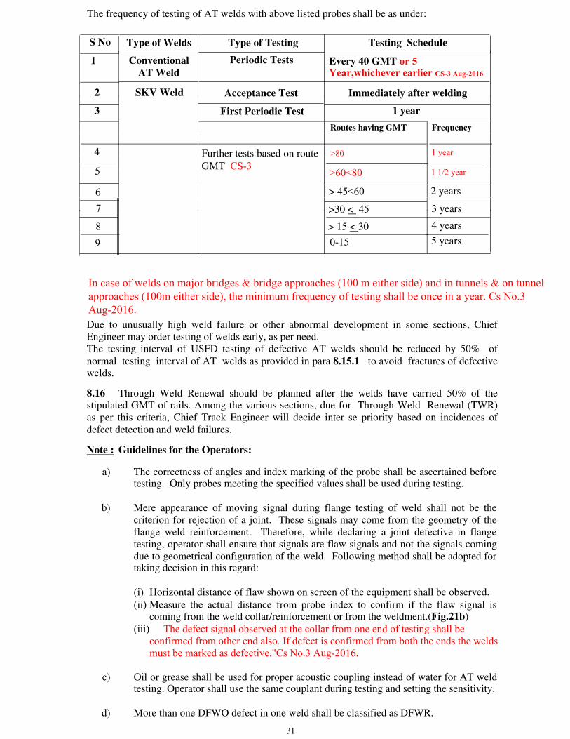
3 1
The frequency of testing of AT welds with above listed probes shall be as under:
S No Type of Welds Type of Testing Testing Schedule
1 Conventional AT Weld
Periodic Tests Every 40 GMT or 5 Year,whichever earlier CS-3 Aug-2016
2 SKV Weld Acceptance Test Immediately after welding
3 First Periodic Test 1 year
Routes having GMT Frequency
4 Further tests based on route
GMT CS-3
> 45<60 2 years
5
>30 < 45 3 years
6
> 15 < 30 4 years
7
0-15 5 years
Due to unusually high weld failure or other abnormal development in some sections, Chief Engineer may order testing of welds early, as per need. The testing interval of USFD testing of defective AT welds should be reduced by 50% of normal testing interval of AT welds as provided in para 8.15.1 to avoid fractures of defective welds.
8.16 Through Weld Renewal should be planned after the welds have carried 50% of the stipulated GMT of rails. Among the various sections, due for Through Weld Renewal (TWR) as per this criteria, Chief Track Engineer will decide inter se priority based on incidences of defect detection and weld failures.
Note : Guidelines for the Operators:
a) The correctness of angles and index marking of the probe shall be ascertained before testing. Only probes meeting the specified values shall be used during testing.
b) Mere appearance of moving signal during flange testing of weld shall not be the criterion for rejection of a joint. These signals may come from the geometry of the flange weld reinforcement. Therefore, while declaring a joint defective in flange testing, operator shall ensure that signals are flaw signals and not the signals coming due to geometrical configuration of the weld. Following method shall be adopted for taking decision in this regard:
(i) Horizontal distance of flaw shown on screen of the equipment shall be observed.
(ii) Measure the actual distance from probe index to confirm if the flaw signal is coming from the weld collar/reinforcement or from the weldment.(Fig.21b)
(iii) The defect signal observed at the collar from one end of testing shall be confirmed from other end also. If defect is confirmed from both the ends the welds must be marked as defective."Cs No.3 Aug-2016.
c) Oil or grease shall be used for proper acoustic coupling instead of water for AT weld testing. Operator shall use the same couplant during testing and setting the sensitivity.
d) More than one DFWO defect in one weld shall be classified as DFWR.
>60<80 1 1/2 year
>80 1 year
89
In case of welds on major bridges & bridge approaches (100 m either side) and in tunnels & on tunnel approaches (100m either side), the minimum frequency of testing shall be once in a year. Cs No.3 Aug-2016.
32
CHAPTER 9
ULTRASONIC TESTING OF FLASH BUTT AND GAS PRESSURE WELDED JOINTS
9.1 Scope: This procedure covers the ultrasonic testing technique of flash butt and gas pressure welded rail joints by using pulse-echo, A-scan examination method of detecting weld discontinuities.
9.1.1 This practice utilises only shear wave probe having 450 & 700 refracted angle in steel, 450
probes to test head and 700 probe to test web and foot of the welded joints.
9.1.2 Significance: It is essential that evaluation be performed properly by trained and qualified personnel.
9.2 Code of procedure
9.2.1 Equipment and accessories
(i) Any RDSO approved model of ultrasonic equipment for Alumino-thermic welded rail joints as per RDSO specification No. M&C/NDT/129/2005 or its latest version.
(ii) Two single crystal 450 2 MHz probes, one single crystal 700 2 MHz probe.
(iii) 00 4 MHz double crystal probe (00 2 MHz single crystal probes, shall be used to checkequipment characteristics.)
(iv) Battery with specific voltage suitable for the USFD to be used.
(v) Battery charger
(vi) Voltmeter
(vii) Standard rail piece of 2.5 m length having standard simulated defects at standardlocations (Fig. 4).
(viii) Calibration block 60 X 50 X 50 mm of steel grade 45C8 to IS : 1875 – 1992.
(ix) Steel measuring tape.
(x) IIW-VI or V2 block
9.3 Pre-requisite
(i) Coupling condition/surface preparation: The protruding upset metal around weldedjoint shall be removed by any suitable mechanical means in such a way that theremaining protruded metal does not produce sharp corner and the finished surface of theprotruded metal if any left should merge smoothly into the surfaces of the adjacent basemetal. The scanning surfaces must be free from weld spatter, scale, dirt, rust and extremeroughness on each side of the weld for a distance equal to 200 mm.
33
Couplant: The couplant should wet the surfaces for the probes and the scanning surfaces and eliminate any air space between the two. Depending upon availability and feasibility of the testing, oil or grease can be used as couplant.
(ii) Calibrate the depth range of ultrasonic flaw detector with the help of 60 X 50 X 50 mmsteel block of steel to grade 45C8 to IS : 1875 – 92 .
9.4 Calibration and sensitivity setting
(i) Calibrate the digital ultrasonic weld tester for 165 mm shear wave as per procedure givenat para no. 8.6.1 and after calibration switch over to T/R double crystal mode.
(ii) Connect the 45o probes, one to transmitter connector and the other to receiver connector.Place the 45o probes on standard rail piece as shown in Fig. 24 (a). Move the probesforward and backward alternately and set the gain to achieve 60% height of full screenfrom a 5 mm dia drill hole drilled in head.
(iii) Remove the 45o probes and connect 70o probe (Turn the probe selector T+R i.e. singlecrystal mode). Place the probe at approximately 100mm from the 5 mm dia hole on theweb as shown in Fig. 24(b). Move the probe to and fro from 5 mm dia hole and set thegain to achieve 60% height of full screen and this gain level shall be reference gain fortesting of web and flange of the joints.
(iv) The equipment is now calibrated for depth range of 16.5 mm per main scale division (formachine having 10 main divisions on horizontal scale) to shear wave and gain of theUFD is set separately for conducting the test using 45o and 70o probes.
9.5 Examination of flash butt/gas pressure welded rail joints in depot (Initial testing):
Examination of flash butt welded joints is performed separately for the rail head, web andflange. In case of scanning of weld at rail head, two single crystal 45o angle probes of 2.0MHz shall be used, one of which shall act as transmitter and the other as receiver. A 70o
single crystal angle probe of 2 MHz frequency shall be employed for examining thewelds at web and flange. All the above probes have index marks on their housing todenote the point at which the central beam emerges.
9.5.1 Testing of weld at rail head: After calibration has been done, the two 45o angle probes shall be connected to the unit by means of two probes cables one acting as transmitter and other as receiver. The probe selector switch shall be operated in T/R mode in which one works as Transmitter and the other as receiver.
Oil or grease as per specification given at para no 4.1 shall be applied as couplant along the right and left hand side faces of the rail head, up to 100 mm from the joint on both sides of the weld.

34
9.5.1.1 Two 45o angle probes shall be placed and moved along the two side faces of the rail head in the longitudinal direction of the rail. Slight twisting movements, with the beam directed towards the weld, shall be imparted mutually to the probes as shown in the Fig. 24 (a). In order to examine the entire width of rail head as well as the height, maximum mutual displacement at start shall be equal to width of top of rail head. If, for example, the left hand probe is at maximum width displacement away from the weld the right hand probe shall be directly over the weld and vice-versa. The probe shall then be advanced from the weld as shown in the Fig. 24 (a). The movement shall be continued until the probes are in reversed positions with respect to the beginning of the test. This operation shall be repeated 3-4 times and at the end of each traverse slight horizontal twisting movements shall be given to the probes. Probing may be continued from the other side of the joint also to take care of defects unfavorably oriented to the search beam applied from the other side.
9.5.1.2 Detection of defects: The common flash butt welding defects are lack of fusion and oxide inclusions. They are generally transversally oriented. If the rail head is free from defects, no flaw signal will appear on the screen. If there are flaws, the beam will be reflected at the discontinuities and picked up by the receiver probe. For a particular rail section, the flaw signal shall always appear at a fixed graduation on the horizontal scale. The location of the flaw can be determined by the position of the probes. Invariably the flaw will be on that side of the rail head, which is nearer to the weld. If both the probes are at equal distance from the weld, the flaw will be in the center of the rail head as shown in Fig. 24 (a). An indication of the flaw size can be made from the amplitude of the flaw signal and the extent of the transverse of the probes.
Any welded joint when tested with gain setting specified showing flaw signal shall be considered defective.
9.6 Testing of weld at rail web and flange
9.6.1 Setting of sensitivity: To examine the web and flange locations of flash butt welded rail joints the gain level of flaw detector’s setting shall be changed and set as per para 9.4(iii) and probe selector switch shall be turned to single crystal operation i.e. in T + R mode.
9.6.2 Couplant: Oil or grease as per specification given at para no 4.1 shall be applied as couplant along the right and left hand side surfaces of the rail web and foot up to 100 mm and 180mm. respectively away from the joint on both sides of the weld.
9.6.3 Testing procedure: The probe shall be positioned 100 mm away from the weld in web region and transversed in a zigzag manner towards the weld. The probing should be done on the web so as to cover the entire width as shown in Fig 24 (b). Testing of the flange should be done as per the procedure described in Para 8.9.3 (Fig. 21 (a)).
9.6.4 Detection of defects: To detect flaws in the web, the probe must be twisted slightly in the direction of the web. No flaw signal will appear on the screen if the rail flange and web are sound. If there are discontinuities in the weld, moving flaw signals will appear on the screen. When the flaw signal is at its maximum height, the distance of the probe from the weld joint shall be measured, to determine the location of the flaw. Any welded joint when tested with normal gain setting showing any moving signal shall be considered as defective.
35
9.7 Periodic Testing
9.7.1 Frequency of testing with 00 & 700 probe: Same as for rails and shall be carried out along with rail testing.
9.7.2 Frequency of testing with 700 hand probing for web and flange: Normally there is no need for hand testing after first testing of welds. Additional hand probing be carried out as per para 9.8.
9.8 For Flash Butt Welds: 450 and 700, 2 MHz hand probing for web and flange:
In case of flash butt welds normally there is no need for hand testing (with 450 and 700 probes), however, Chief Engineer may order hand probing with these probes in case failure rates are high in his opinion.
36
CHAPTER 10
ULTRASONIC TESTING OF RAILS REQUIRED FOR FABRICATION OF POINTS AND CROSSINGS
10.1 New rails without bolt holes and suitable for laying in track are used for the fabrication of points and crossings. These rails, therefore, do not have any chance of fish bolt hole cracking or any progressive type of defects. The defects like pipe, seam, lap, inclusions, segregation can only be expected in these rails. Therefore, in the procedure for ultrasonic testing of these rails only normal probe (0o) is required. Probing shall be carried out from top of the rail head, side of the rail head and side of the web. The use of angle probe has not been included as transverse progressive crack of fish bolt hole cracks are not expected. This testing will be undertaken besides visual examination of rails for freedom from any surface defects.
10.2 Scope: This chapter stipulates the ultrasonic testing technique of new rails required for fabrication of points and crossings by hand probing using ultrasonic flaw defector and lays down the acceptance standard.
10.3 Accessories
10.3 .1 Probes: One single crystal normal probe 20/25 mm dia, 2/2.5 MHz frequency for checking the efficiency of the ultrasonic flaw detector. One double crystal normal probe of 4 MHz frequency, 18mm dia (overall), stainless steel casing and with perspex insert having a path length equal to 50 mm of steel required for testing of rails.
Both the probes shall meet the requirement of the tests stipulated in equipment specification.
10.3.2 Battery: The battery shall be a rechargeable, plug-in type (preferably Ni-Cd type) 6V/12V suitable for working about eight hours continuous operation per charge.
10.3.3 Battery charger: The battery charger shall be suitable for charging the battery provided with the flaw detector.
10.3.4 Co-axial cable: Two meter co-axial cable fitted with BNC connector for connection with single crystal probe.
10.3.5 Calibration block: 60x50x50mm block of steel to grade 45C8 of IS:1875 – 1992.
10.3.6 Standard test rail: The rail piece shall be 250/300 mm in length preferably of the same section used for the manufacture of crossings, having 1.5 mm dia and 2.0 mm dia flat bottom holes drilled along the central axis of the head, web and foot locations as indicated in Fig. 25.
10.3.7 Checking the sensitivity of the probe: The double crystal normal probe shall be able to detect 1.5 mm, 2.0 mm and 2.0 mm dia flat bottom holes in the rail head, web and foot respectively of the standard test rail. The amplitude of the peaks shall be set at 60% height.
10.4 Testing procedure
10.4.1 Surface preparation: The probing faces of the rail shall be cleaned with hard wire brush to make it free from dirt, etc. for achieving acoustic coupling.
3 7
10.4.2 Checking the equipment: Check the correct functioning of the flaw detector or probe and adjust the sensitivity of the unit with standard test rail as in para 10.3.7
10.4.3 Calibration: Calibrate the unit for 300mm range for testing the rail while probing from top of the rail and for 100mm range while testing from the side head and web.
10.4.4 Testing: After calibration of the unit the rails shall be tested manually using double crystal normal probe 4.0 MHz frequency with water/oil as couplant. The rails shall be tested by probing from the rail head top, rail head side and web. Typical oscillogram pattern for various probe positions are given for guidance as indicated below:
(i) Probing from the rail table: Oscillogram pattern for sound rail will be as given at Fig.5.
The pattern obtained on the defective rails will be as in Fig.14 for segregation, Fig.11for vertical longitudinal split in web.
(ii) Side probing from rail head: Oscillogram pattern for sound rail shall be as given atFig.9.
The pattern obtained on defective rails will be as given in Fig.10 for vertical split in head.
(iii) Side probing from web: Oscillogram pattern for sound rail shall be as given in Fig.12.
The pattern obtained on defective rails will be as given in Fig.13 for vertical split inweb.
10.5 Acceptance standards: Any flaw peak appearing on the cathode ray tube of amplitude higher than 60% of the full screen height shall indicate a defective rail and such rails shall not be used for fabrication of points and crossings.
10.6 Guidelines for USFD testing of tongue rail of point & crossing in service.10.6.1 For purpose of USFD testing of tongue rails of points and crossings, the tongue rail can be demarcated in three zones as under:
a. Zone-I : This part of tongue rail of point & crossings where full width of rail head is available, shall be covered in normal rail testing using double rail tester. In some of the switches in which guide roller of double rail tester binder the movement of trolley up to full width of rail head part, lower dia of guide roller shall be used.
b. Zone-2 : This part of tongue rail shall be tested manually using 70° /2 MHz , Single crystal probe having crystal size 20 dia. or 20x20 mm square crystal.
c. This part of the tongue rail shall be examined visually. 10.6.3 Classification of defects : The defect classification shall be made as per provisions given in item l(A), 2(A) , 3 (A) and 4(A) of Annexure-II-A of 'Manual for Ultrasonic testing of rails & welds, (Revised-2012)' However, in zone-2 provisions given in item 2(A) and 3 (A) of Annexure-II-A of 'Manual for U1trasonic testing of rails & welds, (Revised-2012)' shall be applicable. 10.6.4 Action to be taken after detection of defects: SE/JE (P.Way)/USFD shall impose speed restriction of 30 Kmph or stricter immediately and to be continued till flawed tongue rail is replaced which should be done within 3 days of detection. Cs No.3 Aug-2016.
38
CHAPTER 11
ULTRASONIC TESTING TECHNIQUE OF WORN OUT POINT AND SPLICE RAILS PRIOR TO RECONDITIONING BY WELDING AND SWITCH EXPANSION JOINT
11.1. The worn out points and crossings are taken to the Reconditioning Depot for reclamation of the same by suitably depositing hard facing electrode over the worn out areas to enhance the service life and also for effecting savings thereby. As per extant practice, the worn out areas of the wing rails and point and splice are ground for removing loose metals and oxides over the surface before undertaking welding. Freedom from any fatigue crack over the surface to be built-up is also ensured by MPI/DPI before reclamation. As the nose portion of the crossing consisting of the point and splice is subjected to heavy impact and dynamic stresses during service, it is felt necessary to check them ultrasonically to ensure their freedom from any internal flaw prior to reconditioning, so that the defective points and splices can be rejected for ensuring safety in the train operation.
11.2 Scope: This testing procedure stipulates the ultrasonic testing techniques of worn out point and splice rails which need reclamation. Zone I of the crossing shall be tested utilising probes fitted in USFD trolley and zone II and III shall be tested by hand probing with 0o and 70o probes wherever necessary for detection of internal flaws {Fig. 26 (a)}. The testing is required to be carried out in dismantled condition in the welding depot. It also suggests to subject some vulnerable locations to MPI/DPI to ensure freedom from surface/sub-surface defects.
11.3 Personnel qualification: It is essential that evaluation be performed by properly trained and qualified testing personnel.
11.4 Equipment and accessories
11.4.1 Equipment: Pulse-echo type ultrasonic flaw detector approved by RDSO.
11.4.2 Accessories
(i) Probes: The rail test trolley shall have following probes made of PZT, barium titanate orsimilar type of piezo electric crystals:
(ii) (a) Double crystal 4 MHz, 18mm(crystal dia) 0o probe-1 No. fitted in trolley.(b) Single crystal 2 MHz, 20mm(crystal dia)70o probe- 2 No. fitted in trolley.(c) Single crystal 2 MHz, 20mm(crystal dia) 70o probe -1 No. for hand probing.
(iii) Battery with specific voltage suitable for the USFD to be used.(iv) Battery charger(v) Voltmeter.(vi) Standard rail piece of 2.5m length having standard simulated defects at standard locations
(Fig.4)(vii) Calibration block 60 x 50 x 50 mm of steel grade 45C8 to IS: 1875 – 1992.(viii) Steel measuring tape.(ix) IIW-VI or V2 Block(x) Co-axial cable-2.5m length fitted with BNC connector for connection with single crystal
probe.
39
11.4.3 Pre-requisites (i) Battery power: Before undertaking testing, check the power of the battery to ensure that it
is fully charged.(ii) Check the correct functioning of the ultrasonic flaw detector on IIW block as per IS:
12666- 1988.(iii) The couplant should wet the surfaces of the probes and the scanning surfaces properly.
Depending upon the availability and feasibility of the testing – water, oil or grease can beused as couplant.
(iv) Calibrate the depth range of USFD with help of calibration block for 300mm depth range(longitudinal wave) with the help of 0o double crystal 4 MHz probe. The equipment isthus calibrated for depth range of 60/30mm per main scale division for longitudinal wavefor equipment having 5/10 main scale div. on horizontal scale.
11.5 Checking the sensitivity
11.5.1 0o and 70o probes fitted with the rail tester trolley shall be able to detect 5mm dia flat bottom hole at the foot/5mm dia through hole at web-foot junction and 5mm dia through hole at head respectively of the standard 2.5m long test rail. (See Fig.4) and set gain of the USFD so that the flaw signal amplitude is adjusted to 60% of the vertical screen height.
11.5.2 During hand probing by 70o single crystal 2 MHz probe it should be connected with the equipment by a coaxial cable. Turn the probe selector switch to single crystal operation and set the gain of the USFD with 5mm dia drilled hole in the head of the standard rail by side probing. The flaw signal amplitude shall be similarly adjusted to 60% of the vertical screen height.
11.6 Testing procedure {Ref.Fig. 26 (a)}: The points and splices of different turnouts shall be divided into three zones, viz.
Zone –I : To be tested by the rail tester trolley according to accessibility utilising 0o (Towards and 70o probes. the heel of the crossing)
Zone-II: To be tested by 0o and 70o probes provided in the rail tester trolley by (Middle hand probing from the rail head top surface. of the crossing)
Zone–III: To be tested by the 70o 2 MHz single crystal probe by hand probing at (Toward the head portion from both the sides of the head. The web and flange the nose location of zone III shall be tested by the same probe. of the crossing)
Besides the above, the bolt hole locations at the web shall be thoroughly examined visually and magnetic particle/dye penetrate inspection shall be conducted to ensure freedom from cracks since ultrasonic testing of the bolt hole crack on the web is not feasible.

40
11.7 Acceptance standard
Zone I, II &III: Any point or splice when tested with gain setting as specified in para11.5.2, showing any moving signal shall be considered as defective.
11.8 PROCEDURE FOR ULTRASONIC TESTING OF SWITCH EXPANSION JOINT
11.8.1 A number of SEJs have been found to fail in service due to fatigue cracks generated from the bottom of the rail and also from rail head endangering safety. It was therefore considered essential to develop a procedure for detection and classification of defects in SEJs. Details of the procedure are described below.
11.8.2 Scope:This procedure stipulates the ultrasonic testing technique of new SEJs as well as those in service and lays down the acceptable standard with regard to defects noticed. In view of the design of the SEJs, testing is to be accomplished by hand probing.
11.8.3. Accessories:
11.8.3.1 Probes: The following probes shall be used for ultrasonic examination of SEJs
(i) 0oNormal probe, 18mm dia./2MHz, Double crystal for time scalecalibration.
(ii) 45o/2MHz, 20x20mm PZT crystal, Single crystal for locating flaws inmiddle of web-flange area.
(iii) 70o/2MHz, 20x20mm PZT crystal, Single crystal for locating flaws innose of the SEJ.
(iv) A 60mmx50mm x 50mm rectangular block of steel to grade 45C8 of IS-1875-1992.
11.8.3.2 Couplant: Water/soft grease/thick oil shall be used as couplant.
11.8.3.3 Cables: Co-axial cable for each probe shall be used. The length shall not exceed 2 meters.
11.8.3.4 Standard test piece: A 1000mm long rail piece having nose of SEJ stock shall be used for preparation of standard test piece. One simulated flaw of 3mm x 5mm shall be made in the bottom of flange as shown in Fig. 26(b) at location A. This simulated flaw shall be used for sensitivity setting of 45o angle probe. Another 5mm. Dia. through hole shall be made in the rail head at location B, 25mm. below the top of the rail surface and away from nose portion (as shown in Fig. 26(b) for sensitivity setting of 70o angle probe.
11.8.4 Range calibration: The time scale shall be calibrated for 500mm longitudinal wave for setting depth range for 45o angle probe and 300mm longitudinal wave for 70oangle probe with the help of 0o (normal) probe. Rectangular block of 60 mm x50 mm x 50 mm steel to 45C8,IS-1875-1992 shall be used.
41
11.8.5 Sensitivity setting
11.8.5.1 The depth range shall be set for 500mm longitudinal wave using normal probe. There after 45o /2MHz single crystal probe shall be placed on the rail head at a distance of 160mm (for 52 Kg.)/ 175mm (For 60 Kg.) approximately from the junction of flange as shown in Fig. 26(c). The probe shall be placed so as to direct the beam towards the simulated flaw as shown in Fig. 26(c). The probe shall be moved towards the saw cut in zig-zag manner so as to get maximum reflection from saw cut. The height of this reflected signal shall be adjusted to 40% of full screen height with the use of gain control knob. This gain setting shall be utilized during examination of SEJ using 45o angle probe while maintaining the movement towards the nose of SEJ.
11.8.5.1.1 Any flaw peak of amplitude higher than 20% of full screen height shall be classified as IMR. The SEJ should be adequately protected till it is replaced.
11.8.5.2 70o angle single crystal probe: The depth range shall be set to 300mm longitudinal wave with the help of normal probe. Thereafter 70o/2MHz single crystal probe shall be placed on the rail head at a distance of approximately 70mm from 5mm dia hole so as to direct the beam towards the hole. The reflection from 5mm dia. hole shall be adjusted to 60% of full screen height with use of gain control. This gain setting shall be utilized during testing of SEJ while testing with 70o angle probe with probe movement towards SEJ.
11.8.5.2.1 Any flaw peak of amplitude higher than 20% of full screen height shall be classified as IMR. The SEJ should be adequately protected till it is replaced.
11.8.6 Testing frequency : Same as that for normal track as stipulated in the need based concept.
Note: The probe positions indicated are for 52kg rail section. For other rail sections, the distance may be suitably modified.
11.9 Procedure for ultrasonic Testing of tongue rail of SEJ
11.9.1 Scope :
An ultrasonic test procedure has been prepared for detecting defects in tongue rail at location where sharp change in one of the flange portion has been designed. Study reveals that even a small fatigue of 4 -5 mm width in this location caused failure of tongue rail. USFD procedure has been designed to detect defects smaller than above mentioned width. Physical verification at site of track reveals that ultrasonic testing of vulnerable location of tongue rail of SEJ is not feasible under in situ condition because this portion remains inside the bracket over it. For conducting ultrasonic testing bracket has to be removed for getting access to scanning area.
42
11.9.2 Apparatus required:
a. Equipment: Any RDSO approved model of ultrasonic equipment for Alumino-thermic welded rail joints as per RDSO specification No. M&C/NDT/129/2005 orits latest version.
b. Probes: 70˚/ 2 MHz, 20 mm dia. or 20 x 20 mm square crystal size Single Crystalprobe.
c. Couplant: Soft grease or thick oil shall be used as couplant.
11.9.3. General Condition: Prior to conducting testing, the bracket over the sharpcurvature in the flange portion of tongue rail of SEJ shall be removed. Cleaning offlange with kerosene shall be done to remove dirt oil or grease over it. Flange shallbe smooth and free from pittings otherwise paper grinding shall be carried out forsmoothening the surface.
11.9.4 Sensitivity setting procedure:
11.9.4.1 Standard test piece: The sensitivity of the ultrasonic equipment shall be set with the help of Standard Tongue rail of SEJ test piece containing a 5 mm saw cut at sharp curved location of flange as shown in Fig. 29.
11.9.4.2 Range Calibration: The equipment shall be set for a depth range of 165 mm S-Wave. Connect the 70˚/ 2 MHz probe with ultrasonic equipment and select T + R (Single Crystal) mode by selector switch.
11.9.4.3 Sensitivity Setting: Place the 70˚/ 2 MHz probe at a distance of approx. 110 mm. far from saw cut on the upper zone of flange of tongue rail with beam directing towards the saw cut. Move the probe in slight zigzag manner towards cut direction. The reflection from 5 mm cut shall be maximized and shall be set to 60% full screen height by suitable adjustment of gain control.
11.9.4.4 Test Procedure: The 70˚probe shall be placed on the upper zone of flange at a distance of approx.110 mm far from sharp curve portion with beam directing towards curve portion. Move the probe in slight zigzag manner up to curve portion. This scanning shall be carried out 2-3 times.
11.9.5 Defect Classification: Any flaw signal obtained by 70˚probe of 20% vertical height of screen or more shall be treated as defective tongue rail of SEJ.
11.9.6 For testing the head of tongue rail of SEJ, procedure laid down at para 11.8.5.2 & 11.8.5.2.1 shall be followed by hand probing.
11.9.7 Testing frequency: Frequency of USFD testing of tongue rail of SEJ shall be once in a year.
--------------
43
CHAPTER 12
ULTRASONIC TESTING OF RAILS BY SPURT CAR 12.1 Introduction 12.1.1 Continuous testing of rails by manual flaw detectors is strenuous and demands
continuous concentration on CRT screen, also the speed achievable is only 2/6 track km in a day. An equipment which can shortlist likely defective spots quickly can improve the effectiveness of the testing.
12.1.2 Self Propelled Ultrasonic Rail Testing (SPURT) Car has been procured for this purpose
and is in operation since May’88 over Indian Railways. This car tests both the rails while traveling up to 30 km/h. Most of the testing operations have been automated in this car.
12.2 Description of SPURT Car 12.2.1 SPURT Car has water supply system with a capacity of 4000 litres guiding system for
probe beam positioning and air system for lifting and lowering of probe. Probes used are of the following types:
Probes Defect type
0o (Normal) Horizontal flaws
70o Central Vertical transverse flaw (forward and backward) 70o side wise Vertical transverse flaw 35o (forward and backward) Star cracks
550 Vertical longitudinal flaws.
12.2.2 As SPURT car tests at higher speed, observation for flaws can not be done manually. Identification of defect is done electronically according to laid down logics. Also it has computer for tabulating, printing and storage of data. 12.2.3 Comparative characteristics of manual USFD tester and SPURT car are tabulated below:
SPURT car USFD manual machine
Real time recording of defects. No automatic recording of defect.
Analysed by computer hence less strenuous. Testing requires sustained and intense Concentration.Testing is objective. Testing depends on the interpretation by operator.
44
SPURT car USFD manual machine
Testing of 80-120 track km per day. Testing of 2 to 6 track km per day.
Only ultrasonic information is available Ultrasonic information is supplemented by and severity classification is dependent visual information also. So severity on visual information. So classification classification is done. is not possible.
Repetition of test at a spot is difficult due Repetition of test at a spot can be conveniently to speed and path constraint done
To take advantage of both machines, the method used by Railways having SPURT car is to use both as complementary to each other. SPURT car short lists the likely defective spots and manual equipment is used to check only these locations. During this check the severity classification is done.
12.3 Locations not tested by SPURT Car
12.3.1 Fishplated joint causes damage to SPURT car probes and also efficacy of testing reduces depending upon condition of joints, therefore only LWR/CWR lengths are normally tested by SPURT car. Also probes are lifted on points and crossings, SEJ’s and buffer rails and these remain untested. At locations fitted with ground rail lubricators, probes are also lifted and hence testing is not done at such locations.
12.3.2 Testing of rail with surface defects like wheel burn and scab is also to be done manually.
12.3.3 The real time out put as well as final defect report contains the information about stretches not tested by SPURT car.
12.4 Role of Railways
12.4.1 From the time of drawing a programme by RDSO for testing of rails by SPURT car until the testing work gets completed, action in Railways is required at three levels.
(i) Headquarter(ii) Devision and(iii) USFD and sectional SE/JE(P. Way)
12.4.2 Headquarter
12.4.2.1 Programme of testing will be drawn by RDSO in consultation with CTE of a Railway. For this, information about LWR stretches, frequency of testing, rail sections will be made available by USFD cell of the Railway to RDSO for drawing the programme of testing.
45
12.4.2.2 On receipt of the programme from RDSO, Engg. headquarter is to get the confirmation of path and deputation of crew by operating branch. It is to be ensured that proper messages are transmitted by operating branch to all concerned. Reference is also to be made to Rly. Board’s letter No. 90/Track III/TK/72 dated 9.7.90 in this regards. Relevant extracts are reproduced below:
The monitoring special shall be accompanied by following officers from the railway and division:
All routes Any officer from the track modernization cell preferably dealing with rail testing and SE/JE(P.Way)/USFD of the section.
Division Sectional DEN/AEN
One nominated Sr.DEN/DEN at the divisional headquarter shall ensure that there is proper liaison in the control office to ensure suitable path for the monitoring special. Any other special requirement as indicated by RDSO should also be taken care of. The confirmation of the programme is also to be conveyed back to RDSO.
12.4.2.3 Headquarter is also to ensure through divisions for any other assistance requested by RDSO for successful and effective testing by SPURT car. Clear instructions are to be issued to division that sectional AENs/DENs should accompany SPURT car and movement should be watched by Sr.DENs with proper intercommunication.
12.4.2.4 For follow up testing within reasonable time of 10-15 days after the SPURT car run, additional USFD machines are to be sent to the section. The distribution of machines and operators is to be programmed at this stage by USFD cell of headquarter. Also push trolley are to be provided to USFD operators so that average progress of about 8 km follow up testing is achieved.
12.4.3 Division
12.4.3.1 Though the programme of running is confirmed initially by COM, yet the real day-to-day control is at divisional level and divisions role is most critical in effective utilization of SPURT car.
12.4.3.2 On receipt of testing programme from headquarter, Sr.DEN will study the same along with COM confirmation and actual train paths available. Slight modifications in timing, keeping the constraints that (i) the testing can start earliest 8 o’clock (ii) spread of working should not be much and (iii) testing to be done in day light, is possible. Keeping all these in view, testing path is to be planned in consultation with operating branch and the path schedule is to be drawn and get confirmed by operating branch. RDSO official in charge of SPURT car is to be informed about the change, in advance.
12.4.3.3 At the time of testing, sectional AENs, SE/JE(P. Way) and SE/JE(P. Way)/USFD are to accompany the test special. During the run, AEN will liase with control, Sr.DEN and Sr.DOM regarding path. It should be ensured that movement is through main line only to avoid any length untested.
12.4.3.4 At the end of the run SPURT car is to stabled in proper siding. It may also require fuelling and watering arrangements as required for SPURT car, for fuelling, watering, shunting and placement, are all to be arranged by AEN.
46
12.4.3.5 AEN is also to ensure that SE/JE(P. Way) USFD knows clearly about the follow up testing to be done. In case knowledge is lacking, RDSO official will coach the SE/JE(P. Way) about the procedure to be followed by him for follow up testing.
12.4.4 SE/JE(P. Way) /USFD 12.4.4.1 During testing
(a) SE/JE(P.Way) will accompany testing run of SPURT car. He will supply the information regarding the section of rails, GMT and left and right rail convention followed in the section.
(b) SE/JE(P.Way) will carry results of last USFD testing with him for prima facie checking of results reported by SPURT car.
(c) After the testing run SE/JE(P. Way) /USFD will collect the testing output for real time, final defect computer out put and statement of the untested stretches for follow up work.
12.4.4.2 Follow up testing
(a) SE/JE(P. Way) /USFD are required to carry out follow up testing on the locations, indicated in final defect report, which gives the location of the defect in kilometer , defect type, and its size. Also the location is paint marked and thus gets identified. The paint marks will be more than the defects contained in final defect report, the excess being caused by definite noise edited later by SPURT car operator. For the sequencing, real time report can be used as in this report number of defects will equal number of paint marks. Ground features like bridges, L-xing, etc. are also reported in output for use as reference in locating a defect.
(b) After locating a spot, the SE/JE(P.Way) will carry out testing for a length of 2 m i.e. 1
m on either side of the spot and classify the defect, if any, according to the criteria laid down.There is a possibility that the spurt car may have been calibrated on conventional threshold values of defect size in rail while the Need Based concept of USFD testing of rails based on a different defect size in rail has already been introduced in the section being tested. In such a situation the follow up testing should be done with the Need Based concept of USFD testing only.
(c) Occasionally spots reported defective by SPURT car in its final defect report may be
found with no defect during follow up testing. Over reporting can occur for following reason.
(i) Electronic or mechanical disturbance caused due to sudden dynamics or intrusion of
foreign objects.
(ii) Physical features like fishplated joints or extra holes being interpreted as flaw.
12.5 Routes tested by SPURT car 12.5.1 SPURT car conducts tests twice a year on the routes given below:

47
(i) New Delhi - Howrah (ii) New Delhi - Mumbai Central (iii) Mathura Jn - Chennai
12.5.2 LWR/CWR track only on the above routes are tested by SPURT car. Fishplated/SWR
track is not tested by SPURT car and will require testing by Railways. 12.6 The stretches left untested by SPURT car should be tested by manual USFD testing
using Need based criteria.

48
CHAPTER 13
REPORTING AND ANALYSIS OF RAIL/WELD FAILURES 13.1 After each fracture FAILURE REPORT shall be prepared as per proforma given in
Annexure –III and Annexure- IV by SE/JE(P. Way) and Divisions respectively. 13.1.1 All the fractured rail/weld pieces of 150mm length on each side of fractured face,
except those attributable to known extraneous causes such as fractures resulting from accidents, series of fractures resulting from passage of flat wheels, etc., shall be sent to Chemist and Metallurgist for detailed investigation in the following cases:
a) Rail failure within 5 years of primary renewal/Spate of premature rail
failures. b) Weld failure within one year of execution. c) Repetitive rail fractures of same rolling mark.
13.1.2 The Chemist & Metallurgist should submit consolidated investigation report to
Headquarters and Director/M&C/RDSO for making out a management information report based on investigation carried out on the above rail failures. The annual briefs made out by RDSO on the analysis of rail fracture must cover these details. Director (M&C) may call for specific samples from Chemist & Metallurgist for confirmation of their findings.
13.1.3 In the following instances, the samples of rail/weld shall be forwarded to
Director/M&C/RDSO.
(a) Rail/ weld samples involved in accident/derailment (b) Rail samples of imported origin failed in service within guarantee
period. 13.2 All the failure reports and defects detected are required to be compiled in the form of
Annexure VI & VII at divisional level. Each weld failure shall be analysed by sectional Sr. DEN/DEN, to ascertain whether the failure is sudden, due to impact or inherent defects such as lack of fusion, micro porosities, formation of fin etc. The data including causes, nature and frequency of defects shall be analysed and managerial decisions required for preventive/ corrective action shall be taken promptly.
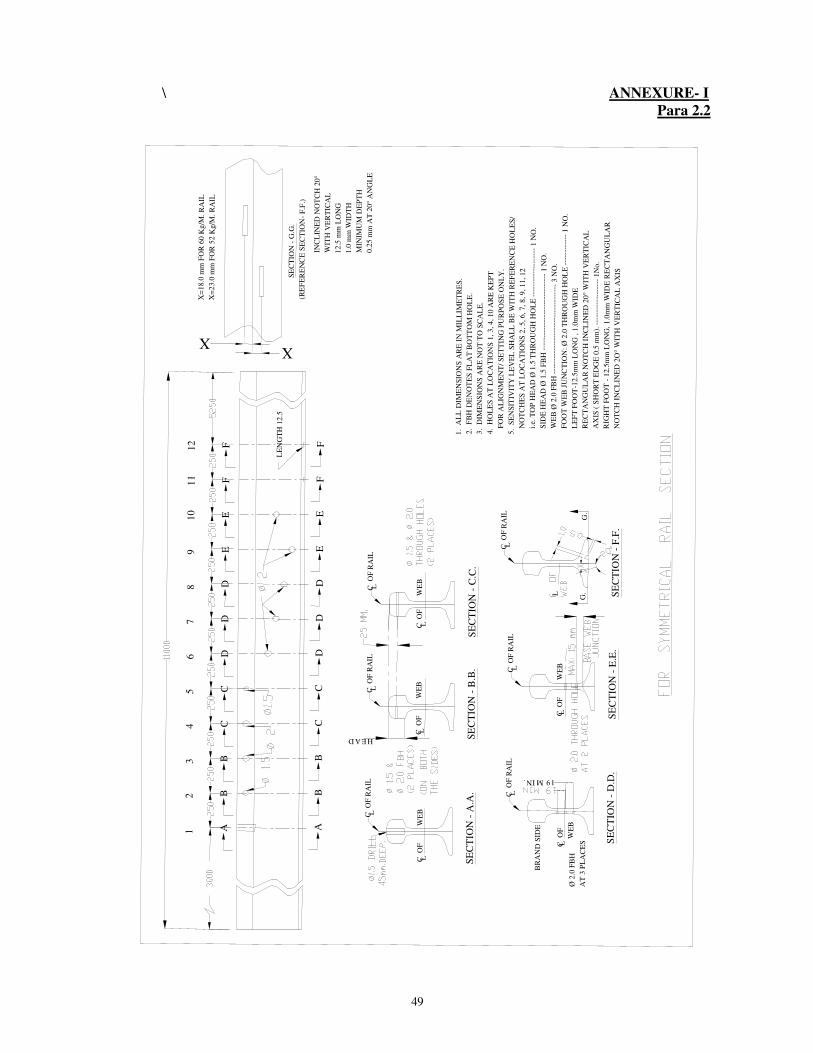
49
\ ANNEXURE- I Para 2.2
1. A
LL
DIM
EN
SIO
NS
AR
E I
N M
I LL
IME
TR
ES
.
2. F
BH
DE
NO
TE
S F
LA
T B
OT
TO
M H
OL
E.
3. D
IME
NS
I ON
S A
RE
NO
T T
O S
CA
LE
.
4. H
OL
ES
AT
LO
CA
TI O
NS
1,
3, 4, 10 A
RE
KE
PT
FO
R A
LIG
NM
EN
T/
SE
TT
ING
PU
RP
OS
E O
NL
Y.
5. S
EN
SIT
IVIT
Y L
EV
EL
SH
AL
L B
E W
ITH
RE
FE
RE
NC
E H
OL
ES
/
NO
TC
HE
S A
T L
OC
AT
ION
S 2
, 5, 6, 7, 8
, 9
, 11, 12
i.e
. T
OP
HE
AD
Ø 1
.5 T
HR
OU
GH
HO
LE
---
----
----
----
----
1 N
O.
SID
E H
EA
D Ø
1.5
FB
H -
----
----
----
--- -
----
----
--- -
- 1 N
O.
WE
B Ø
2.0
FB
H -
----
----
- ---
----
----
- ---
----
----
- - 3
NO
.
FO
OT
WE
B J
UN
CT
ION
: Ø
2.0
TH
RO
UG
H H
OL
E -
----
----
---
1 N
O.
LE
FT
FO
OT
-12.5
mm
LO
NG
, 1
.0m
m W
IDE
RE
CT
AN
GU
LA
R N
OT
CH
IN
CL
INE
D 2
0°
WIT
H V
ER
TIC
AL
AX
IS (
SH
OR
T E
DG
E 0
.5 m
m).
---
----
----
----
---
1N
o.
RIG
HT
FO
OT
- 1
2.5
mm
LO
NG
, 1.0
mm
WID
E R
EC
TA
NG
UL
AR
NO
TC
H I
NC
LIN
ED
2O
° W
I TH
VE
RT
ICA
L A
XIS
12
34
56
78
910
11
12
AAB B
B B
C C
C C
D D
D D
D D
E E
E E
F F
F F
LE
NG
TH
12.5
X=
18.0
mm
FO
R 6
0 K
g/M
. R
AIL
X=
23.0
mm
FO
R 5
2 K
g/M
. R
AIL
XX
INC
LIN
ED
NO
TC
H 2
0°
WIT
H V
ER
TIC
AL
12.5
mm
LO
NG
1.0
mm
WID
TH
MIN
IMU
M D
EP
TH
0.2
5 m
m A
T 2
0°
AN
GL
E
S
EC
TIO
N -
G.G
.
(RE
FE
RE
NC
E S
EC
TIO
N-
F.F
.)
C
O
F R
AIL
L
C O
F
W
EB
L SE
CT
ION
- A
.A.
SE
CT
ION
- B
.B.
SE
CT
ION
- C
.C.
C O
F
W
EB
L C
O
F
W
EB
L
C
O
F R
AIL
L C
O
F R
AIL
L
HEAD
SE
CT
ION
- D
.D.
C O
F
W
EB
L
SE
CT
ION
- E
.E.
C O
F
W
EB
L
C
O
F R
AIL
L C
O
F R
AIL
L
SE
CT
ION
- F
.F.
L
C
O
F R
AIL
L
BR
AN
D S
IDE
19 MIN.
Ø 2
.0 F
BH
AT
3 P
LA
CE
SG
.G
.

50
ANNEXURE- IA Para 2.2
1.
AL
L D
IME
NS
ION
S A
RE
IN
MIL
LIM
ET
RE
S.
2. F
BH
DE
NO
TE
S F
LA
T B
OT
TO
M H
OL
E.
3. D
IME
NS
ION
S A
RE
NO
T T
O S
CA
LE
.
4.
HO
LE
S A
T L
OC
AT
ION
S A
, A
1, B
1,
B3,
B4
, B
5 ,B
6, B
7, C
1, D
3 &
E1 A
RE
KE
PT
FO
R A
LIG
NM
EN
T/
SE
TT
ING
PU
RP
OS
E O
NL
Y.
5. S
EN
SIT
IVIT
Y L
EV
EL
SH
AL
L B
E W
ITH
RE
FE
RE
NC
E H
OL
ES
/
N
OT
CH
ES
AT
LO
CA
TI O
NS
B, B
2, C
, D
, D
1,
D2,
E, F
, F
1
i
.e.
TO
P H
EA
D Ø
1.5
TH
RO
UG
H H
OL
E -
----
- ---
-- 1
NO
.
S
IDE
HE
AD
Ø 1
.5 F
BH
---
----
- ---
----
- ---
----
- ---
----
1 N
O.E
AC
H S
IDE
WE
B Ø
2. 0
FB
H -
----
--- -
----
----
----
----
----
----
----
---
3 N
O.
F
OO
T W
EB
JU
NC
TI O
N:
Ø 2
.0 T
HR
OU
GH
HO
LE
---
----
----
- 1 N
O.
6. L
EF
T F
OO
T-Ø
2.0
TH
RO
UG
H H
OL
E (
LE
NG
TH
MIN
20M
M)
A
T T
HE
CE
NT
RE
OF
SI D
E O
F F
OO
T (
AT
ON
E S
IDE
)---
- ---
1 N
O.
RIG
HT
F
OO
T-Ø
2.0
TH
RO
UG
H H
OL
E (
LE
NG
TH
MIN
20M
M)
AT
TH
E C
EN
TR
E O
F S
IDE
OF
FO
OT
(
AT
OP
P N
OT
IN
SA
ME
LIN
E A
LO
NG
TH
E L
EN
GT
HS
IDE
) S
IDE
)---
--1 N
O.
7. I
T I
S E
SS
EN
TI A
L T
HA
T T
HE
BO
TT
OM
OF
AL
L B
LIN
D H
OL
ES
AR
E
D
RI L
LE
D F
LA
T F
OR
FB
HO
LE
S.
8. S
PE
CIF
IED
HO
LE
TO
LE
RA
NC
E
1
.5 M
M H
OL
E :
1.5
TO
1.5
5 M
M
2.0
MM
HO
LE
: 2
.0 T
O 2
.06
MM
5.0
MM
HO
LE
: 5.0
TO
5.0
8 M
M
(
AL
L O
TH
ER
TO
LE
RE
NC
ES
OF
TH
E A
BO
VE
HO
LE
S S
HA
LL
BE
IN
AC
CO
RD
AN
CE
WIT
H A
ST
M E
428
).
9. N
OT
TO
SC
AL
E
AB
L
F
C
O
F R
AIL

51
Annexure II A (Para 6.3)
CLASSIFICATION OF RAIL/WELD DEFECTS FOR NEED BASED CONCEPT OF USFD
Note : “Any sweeping signal on horizontal baseline that does not extend beyond 2.5 divisions from the left edge of the screen or vice versa shall be recorded as Gauge Corner Cracking (GCC) and not as OBS”.
For Rail Defects S. No
Probe used Nature of defect Oscillogram pattern Classification
1. Normal probe 4MHz (sensitivity set with respect to 100% back wall signal height from rail bottom)
A) Within fishplated area -(i) Any horizontal defect in
head web or foot oflength equal to distancebetween rail end andfirst bolt hole andconnected with the railhead.
(ii) Any horizontal defectconnecting both bolt holes
(iii) Any defect originatingfrom bolt holes and progressing at an angle towards head-web junction or web-foot junction.
No back echo before or after appearance of bolt hole echo with Flaw echo with or without multiples OR Drop in back echo before or after appearance of bolt hole echo with flaw echo with or without multiple
No back echo between bolt hole echo. Flaw echo with or without multiples. No back echo before or after appearance of bolt hole echo with or without flaw echo
IMR
IMR
IMR
B) Outside fish plated area -a) Any horizontal defectprogressing at an angle invertical plane in the rail at thefollowing locations in the track:
i) In tunnel&on tunnelapproaches (100m eitherside)CS-2ii) On major bridges & bridgeapproaches(100m)iii) In the vicinity of holes
near the weld (50 mm for oldAT weld and 75mm for newAT weld from the centre ofweld on either side of weld)
b)Any horizontal defectprogressing at an angle invertical plane in the rail at tracklocations other than (a) above.
No back echo with flaw echo (shifting/without shifting) for any horizontal length OR No back echo and no flaw echo
No back echo with flaw echo (shifting/without shifting) for
horizontal length > 20mm
No back echo with or without shifting flaw echo for horizontal length< 20 mm
IMR
IMR
OBS
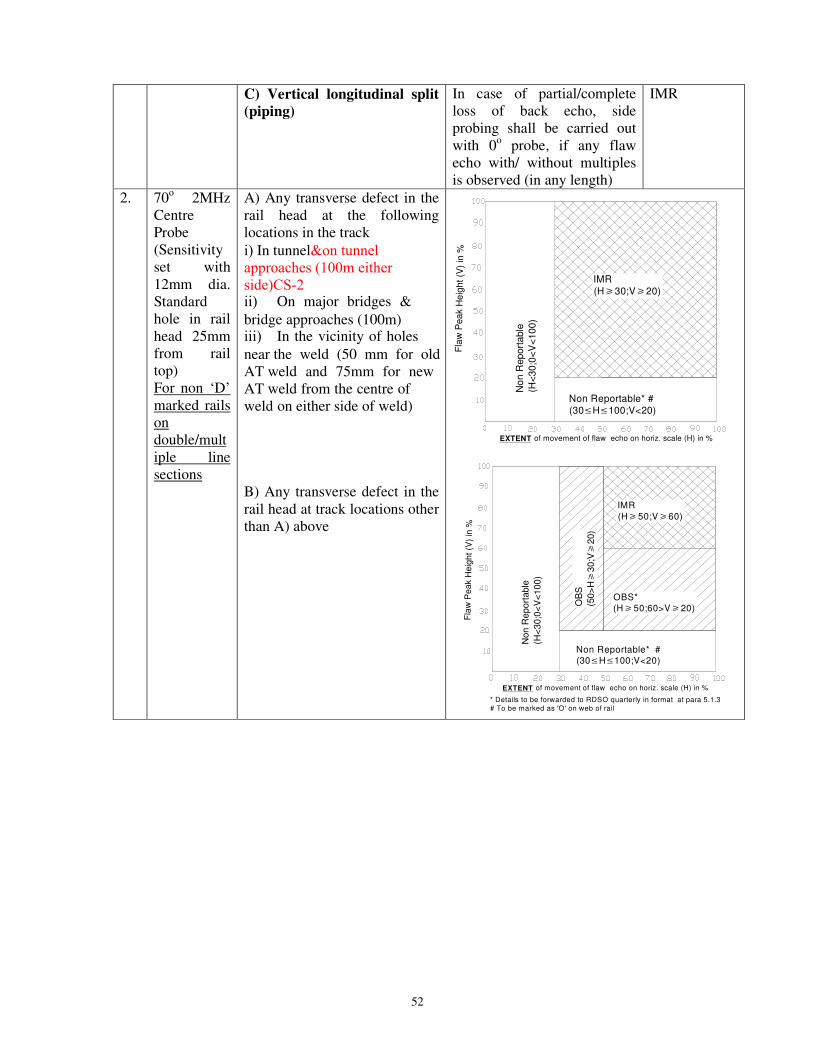
52
C) Vertical longitudinal split(piping)
In case of partial/complete loss of back echo, side probing shall be carried out with 0o probe, if any flaw echo with/ without multiples is observed (in any length)
IMR
2. 70o 2MHz Centre Probe (Sensitivity set with 12mm dia. Standard hole in rail head 25mm from rail top) For non ‘D’ marked rails on double/multiple line sections
A) Any transverse defect in therail head at the followinglocations in the track
i) In tunnel&on tunnel approaches (100m either side)CS-2ii) On major bridges &
bridge approaches (100m)iii) In the vicinity of holes
near the weld (50 mm for old AT weld and 75mm for new AT weld from the centre of weld on either side of weld)
B) Any transverse defect in therail head at track locations otherthan A) above
Fl a
w P
eak H
eig
ht (V
) in
%
No
n R
eport
able
(H<
30;0
<V
<100
)
Non Reportable* #(30≤H≤100;V<20)
IMR
(H�30;V�20)
EXTENT of movement of flaw echo on horiz. scale (H) in %
No
n R
ep
ort
ab
le
(H<
30
;0<
V<
10
0)
Fla
w P
ea
k H
eig
ht
(V)
in %
* Details to be forwarded to RDSO quarterly in format at para 5.1.3# To be marked as 'O' on web of rail
EXTENT
OBS*(H�50;60>V�20)
OB
S
(50
>H�
30
;V�
20
)
IMR
(H�50;V�60)
of movement of flaw echo on horiz. scale (H) in %
Non Reportable* #(30≤H≤100;V<20)

53
3. 70o 2MHz (Centre) Probe (sensitivity set with 12mm dia. Standard hole at rail head 25mm from rail top and with additional gain of 10dB thereon). For all single line sections and ‘D’ marked rails on double /multiple line sections
A) Any transverse defect in therail head at the followinglocations in the track
i) In tunnel&on tunnel approaches (100m either side)CS-2ii) On major bridges &
bridge approaches (100m)iii) In the vicinity of holes
near the weld (50 mm for old AT weld and 75mm for new AT weld from the centre of weld on either side of weld)
B) Any transverse defect in therail head at track locations otherthan A) above
Fla
w P
eak H
eig
ht ( V
) in
%
IMR(0≤H≤100; 20≤V≤100)
Non Reportable(0≤H≤100; V<20)
of movement of flaw echo on horiz. scale(H) in %EXTENT
Fla
w P
ea
k H
eig
ht (V
) in
% OBS(0≤H<50; 20≤V≤100)
IMR(50≤H≤100; 20≤V≤100)
Non Reportable(0≤H≤100; V<20)
of movement of flaw echo on horiz. scale(H) in %EXTENT

54
4. 700 probes Gauge Face & Non-gauge Face side (Sensitivity set on 5mm FBH)
A) Any transverse defect in therail head on gauge face side/Non-gauge Face at thefollowing locations in the track
i) In tunnel&on tunnelapproaches (100m either side)CS-2ii) On major bridges &
bridge approaches (100m)iii) In the vicinity of holes
near the weld (50 mm for oldAT weld and 75mm for newAT weld from the centre ofweld on either side of weld)
B) Any transverse defect in therail head on gauge face/ Non-gauge Face side at tracklocations other than A) above
Fl a
w P
eak H
eig
ht (V
) in
%
Non Reportable(H<15; V<20)
Non Reportable* #
(H�15;V<20)
Non
Rep
ort
able
(H<
15
;V�
20
)
IMR
(H�15;V�20)
EXTENT of movement of flaw echo on horiz. scale (H) in %
Fla
w P
eak H
eig
ht
(V)
in %
No
n R
ep
ort
ab
le
(H<
15;V�
20
)
Non Reportable* #(H�15;V<20)
OB
S
(15≤
H<
30;V�
20)
OBS*(H�30;20≤V<60)
IMR(H�30;V�60)
Non Reportable(H<15V<20)
EXTENT of movement of flaw echo on horiz. scale (H) in %
* Details to be forwarded to RDSO quarterly in format at para 5.1.3# To be marked as 'O' on web of rail
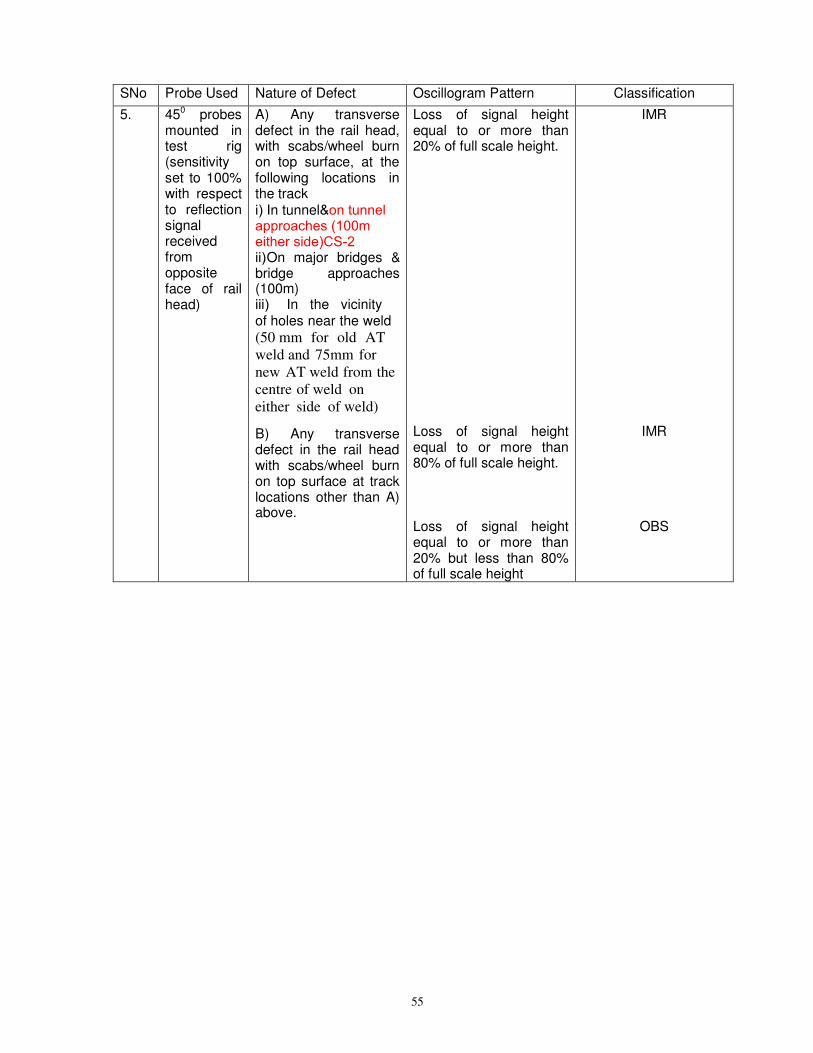
55
SNo Probe Used Nature of Defect Oscillogram Pattern Classification
5. 450 probes mounted in test rig (sensitivity set to 100% with respect to reflection signal received from opposite face of rail head)
A) Any transversedefect in the rail head,with scabs/wheel burnon top surface, at thefollowing locations inthe tracki) In tunnel&on tunnel approaches (100m either side)CS-2ii)On major bridges & bridge approaches (100m)iii) In the vicinity of holes near the weld (50 mm for old AT weld and 75mm for new AT weld from the centre of weld on either side of weld)
B) Any transverse defect in the rail head with scabs/wheel burn on top surface at track locations other than A) above.
Loss of signal height equal to or more than 20% of full scale height.
Loss of signal height equal to or more than 80% of full scale height.
Loss of signal height equal to or more than 20% but less than 80% of full scale height
IMR
IMR
OBS
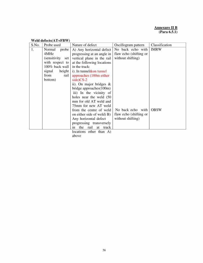
56
Annexure II B (Para 6.5.1)
Weld defects(AT+FBW) S.No. Probe used Nature of defect Oscillogram pattern Classification 1. Normal probe
4MHz (sensitivity set with respect to 100% back wall signal height from rail bottom)
A) Any horizontal defectprogressing at an angle invertical plane in the railat the following locationsin the track:
i). In tunnel&on tunnelapproaches (100m either side)CS-2ii). On major bridges &bridge approaches(100m)
iii) In the vicinity ofholes near the weld (50mm for old AT weld and75mm for new AT weldfrom the centre of weldon either side of weld) B)Any horizontal defectprogressing transverselyin the rail at tracklocations other than A)above
No back echo with flaw echo (shifting or without shifting)
No back echo with flaw echo (shifting or without shifting)
IMRW
OBSW

57
2. 70o 2MHz Centre probe (Sensitivity set with 12mm dia. Standard hole at rail head 25mm from rail top)
A) Any transverse defectin the rail head at thefollowing locations in thetrack
i) In tunnel&on tunnel approaches (100m either side)CS-2ii) On major bridges
& bridge approaches (100m)iii) In the vicinity of holes near the weld (50 mm for old AT weld and 75mm for new AT weld from the centre of weld on either side of weld)
B) Any transverse defect in the rail
at track locations other than A) above
No
n R
ep
ort
ab
le
(H<
30
;0<
V<
100
)
Fla
w P
ea
k H
eig
ht (V
) i n
%
Non Reportable* #(30≤H≤100;V<20)
IMRW(H�30;V�20)
EXTENT of movement of flaw echo on horiz. scale (H) in %
Fla
w P
eak H
eig
ht (V
) in
%
Non R
ep
ort
able
(H<
30;0
<V
<100)
Non Reportable* #(30≤H≤100;V<20)
OB
SW
(50>
H�
30;V�
20)
OBSW*(H�50;60>V�20)
IMRW(H�50;V�60)
of movement of flaw echo on horiz. scale (H) in %EXTENT
* Details to be forwarded to RDSO quarterly in format at para 5.1.3
# To be marked as 'O' on web of rail

58
3. 700 probes Gauge Face &
Non-gauge Face side Probe (Sensitivity set on 5mm FBH)
A) Any transverse defectin the rail head on gaugeface/ Non-gauge Faceside at the followinglocations in the track
i) In tunnel&on tunnel approaches (100m either side)CS-2ii) On major bridges
& bridge approaches (100m)iii) In the vicinity of holes near the weld (50 mm for old AT weld and 75mm for new AT weld from the centre of weld on either side of weld)
B) Any transverse defect in the rail head on gauge face/ Non-gauge Face side at track locations other than A) above
Fl a
w P
ea
k H
eig
ht (V
) in
%
Non Reportable(H<15;V<20)
Non Reportable* #(H�15;V<20)
No
n R
ep
ort
ab
le
(H<
15
;V�
20
)
IMRW(H�15;V�20)
of movement of flaw echo on horiz. scale(H) in %EXTENT
Fla
w P
eak H
eig
ht (V
) in
%
No
n R
epo
rtab
le
(H<
15;V�
20)
Non Reportable* #(H�15;V<20)
OB
SW
(15≤
H<
30;V�
20)
OBSW*
(H�30;20≤V<60)
IMRW(H�30;V�60)
Non Reportable
(H<15V<20)
of movement of flaw echo on horiz. scale(H) in %EXTENT
* Details to be forwarded to RDSO quarterly in format at para 5.1.3 # To be marked as 'O' on web of rail
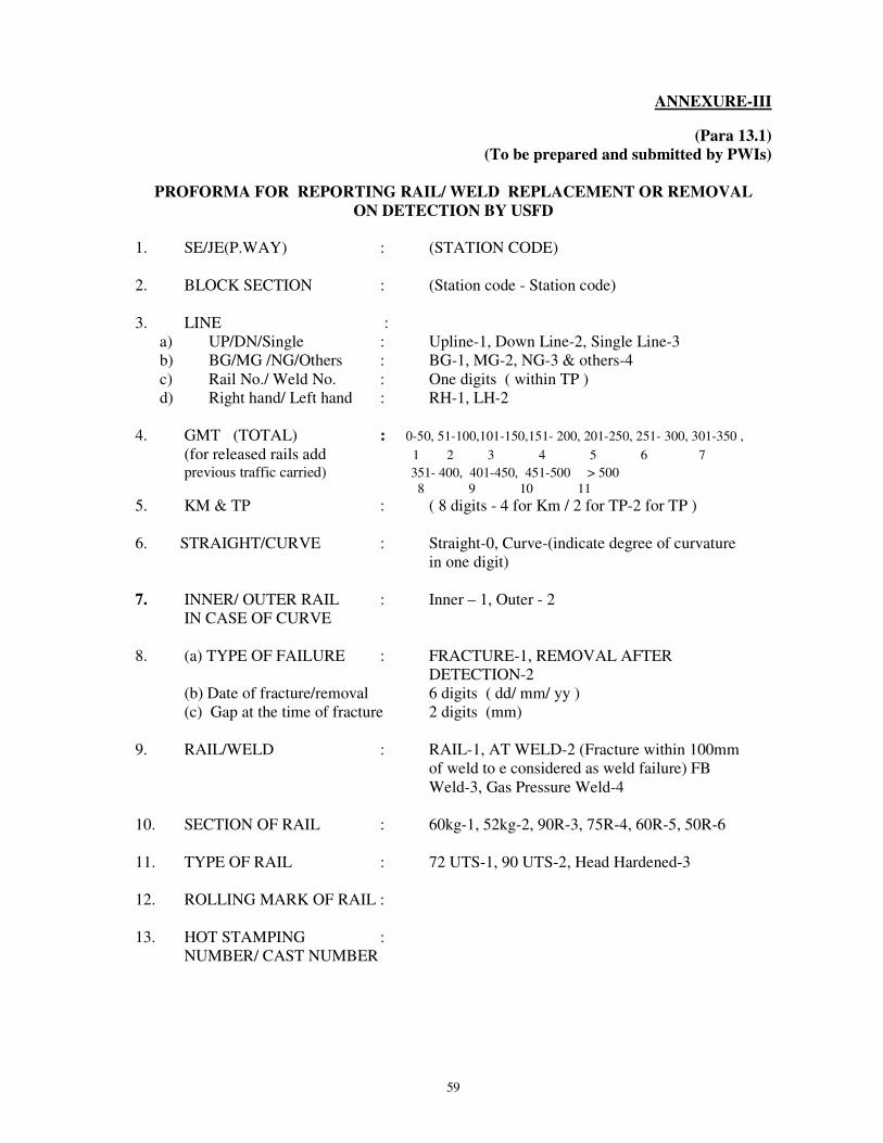
59
ANNEXURE-III
(Para 13.1) (To be prepared and submitted by PWIs)
PROFORMA FOR REPORTING RAIL/ WELD REPLACEMENT OR REMOVAL ON DETECTION BY USFD
1. SE/JE(P.WAY) : (STATION CODE)
2. BLOCK SECTION : (Station code - Station code)
3. LINE : a) UP/DN/Single : Upline-1, Down Line-2, Single Line-3 b) BG/MG /NG/Others : BG-1, MG-2, NG-3 & others-4 c) Rail No./ Weld No. : One digits ( within TP ) d) Right hand/ Left hand : RH-1, LH-2
4. GMT (TOTAL) : 0-50, 51-100,101-150,151- 200, 201-250, 251- 300, 301-350 ,
(for released rails add 1 2 3 4 5 6 7
previous traffic carried) 351- 400, 401-450, 451-500 > 500 8 9 10 11
5. KM & TP : ( 8 digits - 4 for Km / 2 for TP-2 for TP )
6. STRAIGHT/CURVE : Straight-0, Curve-(indicate degree of curvature in one digit)
7. INNER/ OUTER RAIL : Inner – 1, Outer - 2 IN CASE OF CURVE
8. (a) TYPE OF FAILURE : FRACTURE-1, REMOVAL AFTER DETECTION-2
(b) Date of fracture/removal 6 digits ( dd/ mm/ yy ) (c) Gap at the time of fracture 2 digits (mm)
9. RAIL/WELD : RAIL-1, AT WELD-2 (Fracture within 100mm of weld to e considered as weld failure) FB Weld-3, Gas Pressure Weld-4
10. SECTION OF RAIL : 60kg-1, 52kg-2, 90R-3, 75R-4, 60R-5, 50R-6
11. TYPE OF RAIL : 72 UTS-1, 90 UTS-2, Head Hardened-3
12. ROLLING MARK OF RAIL :
13. HOT STAMPING : NUMBER/ CAST NUMBER
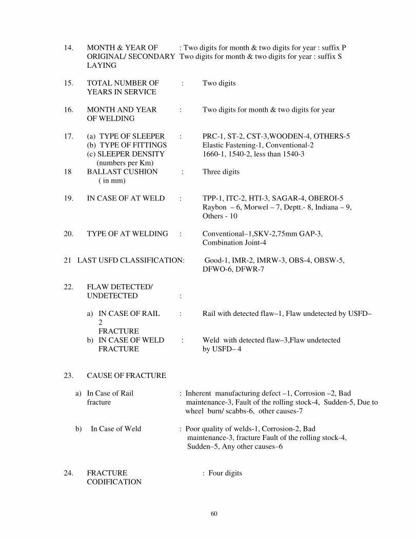
60
14. MONTH & YEAR OF : Two digits for month & two digits for year : suffix P ORIGINAL/ SECONDARY Two digits for month & two digits for year : suffix S LAYING
15. TOTAL NUMBER OF : Two digits YEARS IN SERVICE
16. MONTH AND YEAR : Two digits for month & two digits for year OF WELDING
17. (a) TYPE OF SLEEPER : PRC-1, ST-2, CST-3,WOODEN-4, OTHERS-5 (b) TYPE OF FITTINGS Elastic Fastening-1, Conventional-2 (c) SLEEPER DENSITY 1660-1, 1540-2, less than 1540-3
(numbers per Km)18 BALLAST CUSHION : Three digits
( in mm)
19. IN CASE OF AT WELD : TPP-1, ITC-2, HTI-3, SAGAR-4, OBEROI-5 Raybon – 6, Morwel – 7, Deptt.- 8, Indiana – 9, Others - 10
20. TYPE OF AT WELDING : Conventional–1,SKV-2,75mm GAP-3, Combination Joint-4
21 LAST USFD CLASSIFICATION: Good-1, IMR-2, IMRW-3, OBS-4, OBSW-5, DFWO-6, DFWR-7
22. FLAW DETECTED/UNDETECTED :
a) IN CASE OF RAIL : Rail with detected flaw–1, Flaw undetected by USFD– 2FRACTURE
b) IN CASE OF WELD : Weld with detected flaw–3,Flaw undetected FRACTURE by USFD– 4
23. CAUSE OF FRACTURE
a) In Case of Rail : Inherent manufacturing defect –1, Corrosion –2, Bad fracture maintenance-3, Fault of the rolling stock-4, Sudden-5, Due to
wheel burn/ scabbs-6, other causes-7
b) In Case of Weld : Poor quality of welds-1, Corrosion-2, Bad maintenance-3, fracture Fault of the rolling stock-4, Sudden–5, Any other causes–6
24. FRACTURE : Four digits CODIFICATION

61
25. ORIGIN OF DEFECT AS : Head-1, Web-2, Foot-3, No origin-4
DETECTED BY USFD 26. AVOIDABLE/ : Avoidable-1, Unavoidable -2
UNAVOIDABLE 27. TYPE OF USFD FOR : Need based – 1, Conventional-2
RAIL AND WELD 28. MONTH & YEAR OF
LAST USFD (a) FOR RAIL (including weld) : Two digits each for month and year
(00 +700 Probe) (b) Flange testing of weld : Two digits each for month and year
(700 2 MHz Probe) 29. FOR WELDS IF NOT TESTED, : YES-1, NO-2 WHETHER FISH PLATED BY JOGGLED FISH PLATE WITH TWO TIGHT CLAMPS 30. IN CASE OF WELD FRACTURE : YES-1, NO-2 WHETHER BOLT HOLES
AVAILABLE 31. IN CASE OF CWR/LWR a) Date of last distressing : Two digits each for date, month & year b) distressing temperature : Two digits 32. IN CASE OF SWR/FP a) Date of last gap survey : Two digits each for date, month & year b) Date of rectification : Two digits each for date, month & year 33. IN CASE OF CRACK ORIGINATING FROM BOLT HOLE a) Date of oiling/greasing : Two digits each for date, month & year b) Were the bolts tight : Yes-Y, No-N c) Were the bolt holes chamfered : Yes-Y, No-N
d) In case of elongation, size of : (Two digits in mm) bolt hole e) Sleeper spacing : Normal-1, Joint sleeper spacing-2
34. IN CASE OF FAILURE OF AT : Yes-Y, No-N WELDS WITHIN 2 YEARS

62
35. IN CASE OF FAILURE OF FBW a) Name of welding plant : Station code b) Panel No. : (Three digits) c) Joint No. : (Two digits) 36.LOCATION OF FRACTURE : Fish plated Zone(Bolt hole area)- 1, Mid rail-2 (For rail fracture) SEJ-l ,Glued Joint-4, Point &Crossing-5

63
ANNEXURE-IV (Para 13.1)
DETAILS REQUIRED FOR RAIL/WELD FAILURE ANALYSIS
(Only for guidance for generating data at Division’s level )
1. RAILWAY ZONE : (CR-01, ER-02, NR-03, NER-04, NFR-05, SR-06, SCR- 07, SER-08, WR- 09,ECR-10,ECoR-11,NCR-12, NWR-13,SECR-14, SWR-15, WCR-16)
2. DIVISION : As per code 3. SE/JE(P. WAY) : (Station code) 4. SECTION (NAME OF LINE OR BRANCH) : (Station code) 5. BLOCK SECTION : (Station code-Station code) 6. DATE OF FRACTURE/REMOVAL : Two digits each for date, month and year 7. TIME OF DETECTION : 4 Digits( 2 for hours/2 for minutes) 8. ROUTE CLASSIFICATION : (A, B, C, D, DS, ES, E, Q, R1,R2,R3, S) 9. LENGTH OF BLOCK SECTION (in KM) : (Two digits) 10. MAX. PERMISSIBLE SPEED : (Three digits) 11. MAX. PERMISSIBLE AXLE LOAD : 20.32T-1, 22.1T-2, 22.86T-3, above 22.86T-4, MG-5 12 GMT(ANNUAL) : 0-5, 5-10, 10-15, 15-20, 20-25, 25-30, 30-35, 35-40, > 40
1 2 3 4 5 6 7 8 9 13. CWR/LWR/SWR/FISH PLATED : CWR-1, LWR-2,SWR-3,FISH PLATED-4 14. LINE :
(a) Up/down/single : Upline-1, Down line-2, single line-3 (b) BG/MG/NG/Others : BG-1, MG-2, NG-3, Others-4
15. RAIL NUMBER/ WELD NUMBER IN TP : (two digits) 16. RAIL – RIGHT HAND OR LEFT HAND : RH-1, LH-2 17 GMT(TOTAL) : 0-50, 51-100,101-150,151- 200, 201-250, 251- 300, 301-350 , 351- 400, 401-450,
(for released rails 1 2 3 4 5 6 7 8 9 add previous 451-500, > 500
traffic carried) 10 11
18. KM & TP : (8 digits-4 for Km/2 for TP-2 for TP)
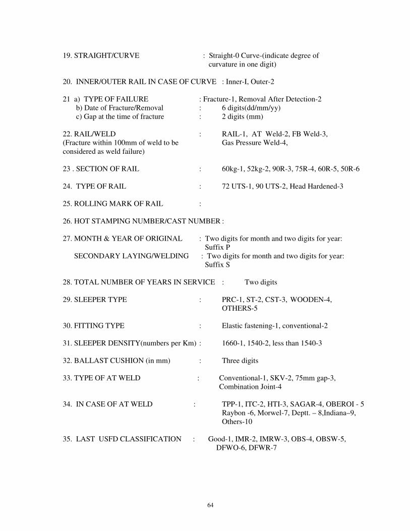
64
19. STRAIGHT/CURVE : Straight-0 Curve-(indicate degree of curvature in one digit) 20. INNER/OUTER RAIL IN CASE OF CURVE : Inner-I, Outer-2 21 a) TYPE OF FAILURE : Fracture-1, Removal After Detection-2 b) Date of Fracture/Removal : 6 digits(dd/mm/yy) c) Gap at the time of fracture : 2 digits (mm) 22. RAIL/WELD : RAIL-1, AT Weld-2, FB Weld-3, (Fracture within 100mm of weld to be Gas Pressure Weld-4, considered as weld failure) 23 . SECTION OF RAIL : 60kg-1, 52kg-2, 90R-3, 75R-4, 60R-5, 50R-6 24. TYPE OF RAIL : 72 UTS-1, 90 UTS-2, Head Hardened-3 25. ROLLING MARK OF RAIL : 26. HOT STAMPING NUMBER/CAST NUMBER : 27. MONTH & YEAR OF ORIGINAL : Two digits for month and two digits for year: Suffix P
SECONDARY LAYING/WELDING : Two digits for month and two digits for year: Suffix S
28. TOTAL NUMBER OF YEARS IN SERVICE : Two digits 29. SLEEPER TYPE : PRC-1, ST-2, CST-3, WOODEN-4, OTHERS-5 30. FITTING TYPE : Elastic fastening-1, conventional-2 31. SLEEPER DENSITY(numbers per Km) : 1660-1, 1540-2, less than 1540-3 32. BALLAST CUSHION (in mm) : Three digits 33. TYPE OF AT WELD : Conventional-1, SKV-2, 75mm gap-3,
Combination Joint-4 34. IN CASE OF AT WELD : TPP-1, ITC-2, HTI-3, SAGAR-4, OBEROI - 5 Raybon -6, Morwel-7, Deptt. – 8,Indiana–9, Others-10 35. LAST USFD CLASSIFICATION : Good-1, IMR-2, IMRW-3, OBS-4, OBSW-5,
DFWO-6, DFWR-7

65
36. FLAW DETECTED/UNDETECTED a) IN CASE OF RAIL FRACTURE :Rail with detected flaw – 1, Flaw undetected by USFD – 2 b) IN CASE OF WELD FRACTURE : Weld with detected flaw – 3, Flaw undetected by USFD– 4 37. CAUSE OF FRACTURE
a) IN CASE OF RAIL FRACTURE : Inherent manufacturing defect –1, Corrosion –2, Bad maintenance-3, Fault of the rolling stock-4, Sudden-5, Due to wheel burn/ scabs -6, other cause-7
b) IN CASE OF WELD FRACTURE : Poor quality of welds-1, Corrosion-2, Bad maintenance-3, Fault of the rolling stock-4, Sudden-5, any other cause-6
38. FRACTURE CODIFICATION : Four digits 39.Origin of defect as detected by USFD : Head-1, Web-2, Foot-3, No origin-4 40. AVOIDABLE/UNAVOIDABLE : Avoidable-1, Unavoidable -2 41. TYPE OF USFD FOR RAIL AND WELD: Need based – 1, Conventional-2 42. MONTH & YEAR FOR LAST USFD : (a) FOR RAIL (including weld) (00 +700 Probe) :Two digits each for month and year (b) Flange testing of weld (700 Probe) :Two digits each for month and year 43. FOR WELDS IF NOT TESTED, WHETHER : YES-1, NO-2 FISH PLATED BY JOGGLED FISH PLATE WITH TWO TIGHT CLAMPS 44. IN CASE OF WELD FRACTURE : YES-1, NO-2 WHETHER BOLT HOLES AVAILABLE 45 IN CASE OF CWR/LWR
a) Date of last destressing : Two digits each for date, month and year b) Destressing temperature : Two digits
46. IN CASE OF SWR/FP a) Date of last gap survey : Two digits each for date, month and year b) Date of rectification : Two digits each for date, month and year 47. WHETHER FAILURE OF AT WELDS : YES-Y, NO-N WITHIN 2 YEARS
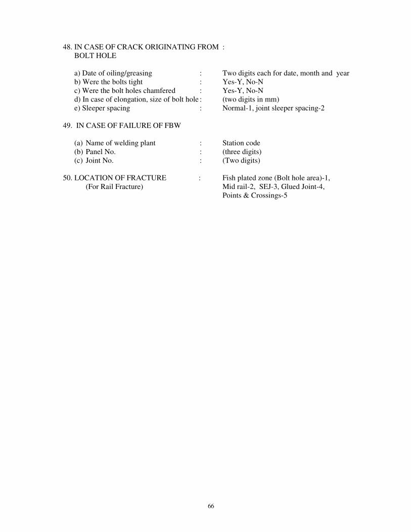
66
48. IN CASE OF CRACK ORIGINATING FROM : BOLT HOLE a) Date of oiling/greasing : Two digits each for date, month and year b) Were the bolts tight : Yes-Y, No-N c) Were the bolt holes chamfered : Yes-Y, No-N d) In case of elongation, size of bolt hole : (two digits in mm) e) Sleeper spacing : Normal-1, joint sleeper spacing-2 49. IN CASE OF FAILURE OF FBW
(a) Name of welding plant : Station code (b) Panel No. : (three digits) (c) Joint No. : (Two digits)
50. LOCATION OF FRACTURE : Fish plated zone (Bolt hole area)-1, (For Rail Fracture) Mid rail-2, SEJ-3, Glued Joint-4, Points & Crossings-5

67
ANNEXURE –V (Para 6.8)
CHECK LIST OF ULTRASONIC TESTING OF RAIL/WELDS
DIVISION------------------------SECTION----------------------------- LINE: UP/DN/SINGLE ROUTE----------------Km. FROM-----------------TO-----------------DATE---------------------
1. Name of the operators then trained by RDSO Last refresher course done i) ------------------------------------- --------------------------------- --------------------------------ii) -------------------------------------- --------------------------------- -------------------------------
2. Method of Testing : Conventional/Need Based 3. Rail section &Brand Mark : ……………………………………………………. 4. Annual GMT : ……………………………………………………. 5. Whether within service life : ……………………………………………………. 6. Frequency : ……………………………………………………. 7. Date of last Testing : ……………………………………………………. 8. Reason for overdue if overdue : ……………………………………………………. 9. Type of USFD M/C : ……………………………………………………. 10.Model,Manufacturing Year & M/C no. : ……………………………………………………. 11.Visual condition of electronic unit :Very Good/Good/Satisfactory/Not satisfactory 12.Visual condition of trolley :Very Good/Good/Satisfactory/Not satisfactory 13.Date of calibration of M/C : (to be filled up from M/C register) 14.Date of sensitivity setting of M/C : (to be filled up from M/C register) 15.Date of checking of characteristics : (to be filled up from M/C register) 16.Fuction of Controls : ……………………………………………………. 17.Alignment of probes & lifting system : …………………………………………………….
(with respect to the center line)18.Watering arrangement of probes : ……………………………………………………. 19. Date of change of last probes : …………………………………………………….
with probe details
20.Condition of probes:Types of probe Right hand side Left hand side 70o 2
MHz (Flange testing)
45o 2 MHz
70o 2 MHz
(8mm x 8mm)
Description 0o 70oF 70oB 0o 70oF 70oB (Flange testing)
(Flange testing)
Working/Not working Condition of shoes
21. i) Watering condition of Battery : ……………………………………………………. ii) Year of procurement of battery : …………………………………………………….
22.Condition of Audio Alarm : Sounding/ Not Sounding 23.Checking spares with the M/C : Available/ Not available
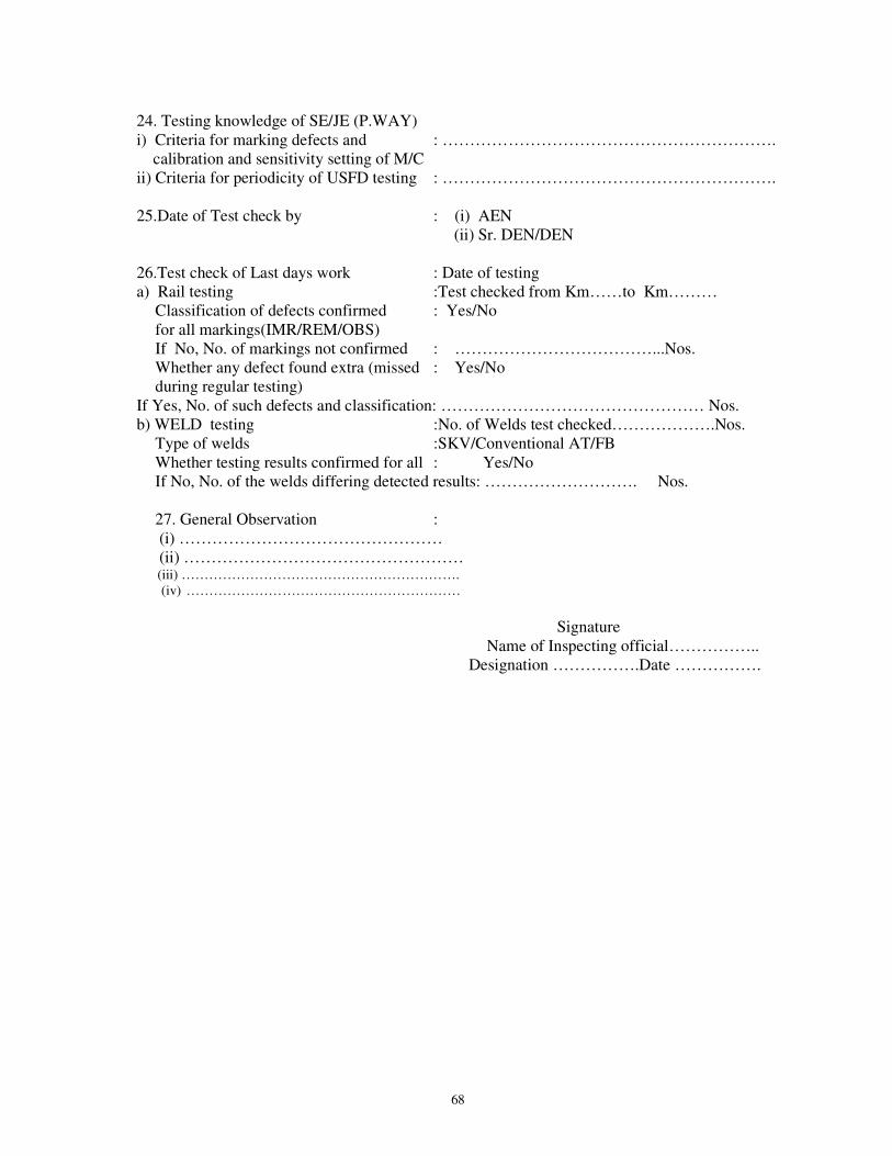
68
24. Testing knowledge of SE/JE (P.WAY) i) Criteria for marking defects and : ……………………………………………………. calibration and sensitivity setting of M/C ii) Criteria for periodicity of USFD testing : ……………………………………………………. 25.Date of Test check by : (i) AEN (ii) Sr. DEN/DEN 26.Test check of Last days work : Date of testing a) Rail testing :Test checked from Km……to Km………
Classification of defects confirmed : Yes/No for all markings(IMR/REM/OBS) If No, No. of markings not confirmed : ………………………………...Nos. Whether any defect found extra (missed : Yes/No during regular testing)
If Yes, No. of such defects and classification: ………………………………………… Nos. b) WELD testing :No. of Welds test checked……………….Nos.
Type of welds :SKV/Conventional AT/FB Whether testing results confirmed for all : Yes/No If No, No. of the welds differing detected results: ………………………. Nos. 27. General Observation : (i) ………………………………………… (ii) ……………………………………………
(iii) ……………………………………………………. (iv) ……………………………………………………
Signature
Name of Inspecting official…………….. Designation …………….Date …………….
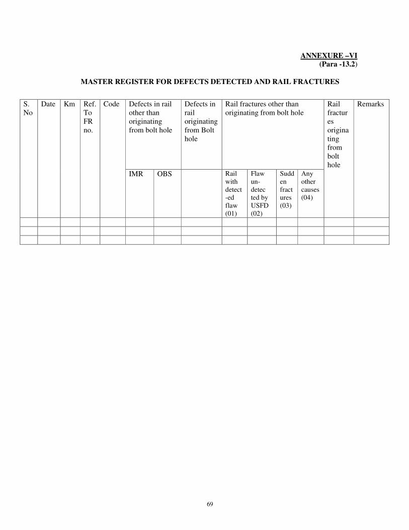
69
ANNEXURE –VI
(Para -13.2)
MASTER REGISTER FOR DEFECTS DETECTED AND RAIL FRACTURES
S. No
Date Km Ref. To FR no.
Code Defects in rail other than originating from bolt hole
Defects in rail originating from Bolt hole
Rail fractures other than originating from bolt hole
Rail fractures originating from bolt hole
Remarks
IMR OBS Rail with detect-ed flaw (01)
Flaw un-detec ted by USFD (02)
Sudden fractures (03)
Any other causes (04)
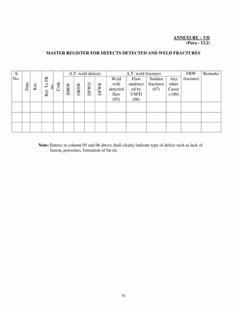
70
ANNEXURE – VII (Para - 13.2)
MASTER REGISTER FOR DEFECTS DETECTED AND WELD FRACTURES
S.No.
Dat
e
Km
.
Ref
. T
o F
R
no
.
Co
de
A.T. weld defects A.T. weld fractures FBW fractures
Remarks
IMR
W
OB
SW
DF
WO
DF
WR
Weld with
detected flaw (05)
Flaw undetect
ed by USFD (06)
Sudden fractures
(07)
Any other Causes (08)
Note: Entries in column 05 and 06 above shall clearly indicate type of defect such as lack of fusion, porosities, formation of fin etc

71
ANNEXURE-VIII (Para 4.3.1)
INSPECTION OF RAIL TESTER AND WORK OF PWI (USFD)
Name of SE/JE (P.WAY)/USFD, Grade & HQ.
Trained by RDSO during.
Last course attended at RDSO…
MACHINE INSPECTED BY SHRI …………………… DATE OF INSPECTION……………………………….
1. MACHINE
i) Make and Sr. No. of the machinea) SRT(ECIL/VIBRONICS/EEC/Paras/Others) … b) DRT(EEC/PARAS/Others)ii) Month & Year of procurement of machineiii) Function of controls.
(On/Off, Gain, H. Shift, Depth,Energy & Reject etc.)
iv) Brightness of the machine.(Base line and flaw peaks)
v) Working of the junction box.(All terminals)
vi) Condition of the probe cables(Connected cables and BNC’s).
vii) Condition of probes-00,70oF & B and 7002 MHz,4502MHz, 7002 MHz SLP(with respect to wear & sensitivity)
viii) Alignment of probes & lifting system.(With respect of centre line.)
ix) Condition of shoes of probes (Un-even wear).Provision of 0.2mm gap.
x) Watering arrangements.(Proper and adequate supplyto different probes).
xi) Checking spares with machine(Wheels-2, Normal probe – 1

72
700 F & B-1, 7002 MHz-1, 45o2MHz - 2 &700 2 MHz SLP – 1, probe shoe, probe holder, battery)
xii) Working condition of Batteries. (Voltageand Specific Gravity) & charging system
xiii) Year of procurement of Battery.
xiv) Condition of Trolley Wheels.
xv) Tools with machine.
xvi) General up-keep of machineand trolley
2. CALIBRATION & SENSITIVITY SETTING OF MACHINE:
i) Availability of IIW Block, multimeter, Standard rail piecewith artificial flaws and Steel block.
ii) Checking of operating characteristics byIIW Block last done.
iii) Sensitivity setting of machinelast done and gain level employed.
iv) Checking of calibration and sensitivitysetting of machine.
3.QUALITY OF TESTING: Sec.-------To------LINE(Single/UP/DN.) Kms/From--------To----------------------
i) Check of last days/week/month work(Comparison with last round testing)by SE/JE (P WAY.)/ (USFD)
ii) Checking of IMR/DFWR of Rails/Welds
4. TESTING KNOWLEDGE OF SE/JE (P WAY):
i) Criteria for marking defects and calibrationand sensitivity setting of machine.
ii) Criteria for periodicity of USFD testing.(As per criteria laid down by Railway Board.)
iii) Policy and latest instructions of USFD.
Signature of Inspecting Officer

73
FIG. 1: ARRANGEMENT OF PROBES FOR TESTING OF NEW RAILS IN STEEL PLANTS

74
FIG. 2A: AREA COVERED BY NORMAL ( 0°) PROBE(FOR A.T. WELD,AREA BELOW NEUTRAL AXIS REMAINS UNTESTED)
NEUTRAL AXIS
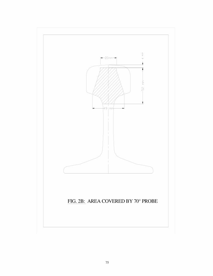
75
FIG. 2B: AREA COVERED BY 70° PROBE
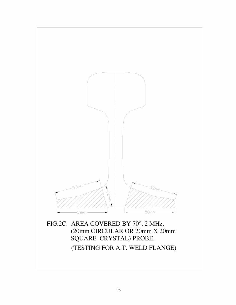
76
FIG.2C: AREA COVERED BY 70°, 2 MHz, (20mm CIRCULAR OR 20mm X 20mm SQUARE CRYSTAL) PROBE.
(TESTING FOR A.T. WELD FLANGE)

77
AREA COVERED BY 70° PROBES IN EQUIPMENT WITH GAUGE FACE CORNER, CENTRE AND
FIELD CORNER PROBES
FIG. 2D: AREA COVERED BY 70° PROBES IN VARIOUS GAUGE FACE CORNER DEFECT DETECTION EQUIPMENT

78
FIG
. 3
-
SE
NS
ITIV
ITY
SE
TT
ING
BL
OC
K F
OR
70
° 2M
Hz (
CE
NT
RE
, G
AU
GE
FA
CE
AN
D N
ON
-GA
UG
E F
AC
E )
PR
OB
ES
1.2
5m
L
ON
G A
LU
MIN
IUM
/ W
OO
DE
N H
OU
SIN
G F
OR
TE
ST
PIE
CE
H
AV
ING
TO
P T
AB
LE
W
IDT
H E
QU
AL
TO
RA
IL H
EA
D W
IDT
H
300
25
40
20°
5Ø
FB
H
15A
LL
DIM
EN
SIO
NS
AR
E IN
mm
.
DR
AW
ING
IS
NO
T T
O S
CA
LE
RAIL HEAD WIDTH
12Ø
TH
RO
UG
H H
OLE
20
25
SL
ICE
FR
OM
RA
IL H
EA
D
APPROX. 100
90°
1.
Th
e s
lice
fro
m r
ail
he
ad
fo
r se
nsitiv
ity s
ett
ing
sh
all
be
fro
m r
ail
of
sa
me
se
ctio
na
l w
eig
ht
wh
ich
is t
o b
e t
este
d (
i.e. fo
r te
sting
on
60K
g/5
2K
g, 9
0R
rails
etc
. th
e
se
nsitiv
ity te
stin
g p
iece
sh
all
be
fro
m 6
0K
g,
52
Kg
, 9
0R
ra
ils r
esp
ective
ly).
2.
In c
ase
of
ma
ch
ine
s h
avin
g p
rovis
ion
of
va
ria
ble
sh
ift
of
ga
ug
e f
ace p
robe
s follo
win
g s
hall
be
ensu
red:
a)
Ma
xim
um
sh
ift
of
pro
be
sh
all
be
lim
ite
d t
o t
he
exta
nt
up
to
wh
ich
th
ere
is n
o lo
ss o
f a
cou
stic
cou
plin
g d
epe
nd
ing
on
rail
top p
rofil
e.
b)
Th
e s
en
sitiv
ity s
ett
ing
sh
all
be
do
ne
at
the
sh
ift
leve
l w
ith
wh
ich a
ctu
al te
stin
g is to b
e c
arr
ied o
ut.
c)
Th
e s
hift
of
pro
be
sh
all
no
t b
e a
lte
red
du
rin
g t
estin
g w
ith
ou
t fr
esh s
ett
ing
at altere
d s
hift .
Old Fig 3

I °'"
'-· ,.
SUCE FROM RAIL HE.AO
I '� --·-
� ll � 0t · I OL.: L. ·, - - - -- r
L � --
�R�0FBH
I I I
K- ;y�- �-..... �o·
-
,;--
11.
i l i , I t I I 111I I I,'
300
·- -
-
4 I120THROUGH HOLE
-----
I ·t
'T
::c
��-,:, I i 1�
--1 �
I
I. fa'--�:J
I .Sm LONG ALUMINIUM/ \AIOODEN HOUSING FOR TEST PIECE HAVING TOP T/>.BLE
WIDTH EQUAL TO RAIL HEAD WIDTH
1 The suce from rail head for sensitivity settmg shall be from ra il of same sectional weight which ,s to be tested (1.e for� on 60Kg/52� SOR raus etc the sensrtwrty testing piece shan be from 60Kg, 52Kg. 90R rails respedrvely}
2. In case or machines nav,ng provision or vanable shift or gauge taoe probes following shall be ensured: a) Maximum shit\ of probe shall be limited lo the extant up to which there Is no loss of acoustic coupling depandlng on rad� l)fO/ile !>) The sensitivity setting shall be done at the shift level with which actual testing 1s to be earned out c) The shifl or probe shall not be altered dunng testing without fresh sel!Jng at altered shot\
f 0 0 ... � era. Q. <(
FtG. 3 - SENSITIVITY SETTING BLOCK FOR 70 ° 2MHz (CENTRE,
GAUGE FACE AND NON-GAUGE FACE ) PROBES
ALL DIMENSIONS ARE IN mm DRAWING IS NOT TO SCALE
> =
:::,:, 1),4 C ""' ('!)• ->
New fig.3 Cs No.3 Aug-2016.
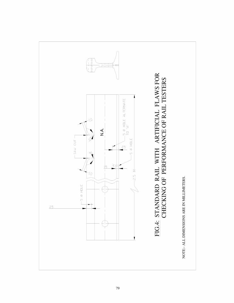
79
FIG
.4:
ST
AN
DA
RD
R
AIL
W
ITH
A
RT
IFIC
IAL
F
LA
WS
FO
R
CH
EC
KIN
G O
F
PE
RF
OR
MA
NC
E O
F R
AIL
TE
ST
ER
S
NO
TE
:- A
LL
DIM
EN
SIO
NS
AR
E I
N M
ILL
IME
TE
RS
.
N.A
.

80
FIG
.5:
RA
IL W
ITH
OU
T F
LA
W (
0°
PR
OB
E)
a -
SU
RF
AC
E E
CH
O.
b -
BA
CK
EC
HO
.
a
20
110
98
76
54
3
b

81
b4
b3
a a -
SU
RF
AC
E E
CH
O.
b -
FL
AW
EC
HO
.
b1
,b2
. .
. M
UL
TIP
LE
FL
AW
EC
HO
ES
910
10
23
45
67
8
b2
b1
b
FIG
.6:
LO
NG
ITU
DIN
AL
HO
RIZ
ON
TA
L S
PL
IT I
N H
EA
D R
EG
ION
(T
YP
E 1
12
&212
, 0°
PR
OB
E)
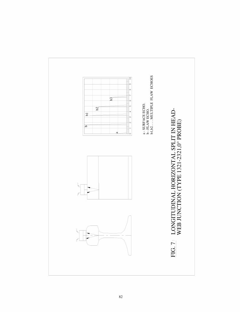
82
LO
NG
ITU
DIN
AL
HO
RIZ
ON
TA
L S
PL
IT I
N H
EA
D-
WE
B J
UN
CT
ION
(T
YP
E 1
321-2
321
,0°
PR
OB
E)
FIG
. 7
a -
SU
RF
AC
E E
CH
O.
b -
FL
AW
EC
HO
.b
1,b
2.
. .
. M
UL
TIP
LE
F
LA
W E
CH
OE
S
b2
a
10
23
45
b1
b
b3
910
67
8

83
FIG
.8:
VE
RT
ICA
L L
ON
GIT
UD
INA
L S
PL
IT I
N H
EA
D (
TY
PE
113
& 2
13
, 0
° P
RO
BE
)
a -
SU
RF
AC
E E
CH
O.
b -
FL
AW
EC
HO
.c
- S
UP
PR
ES
SE
D B
AC
K E
CH
O
61
02
34
59
10
78
c
ba
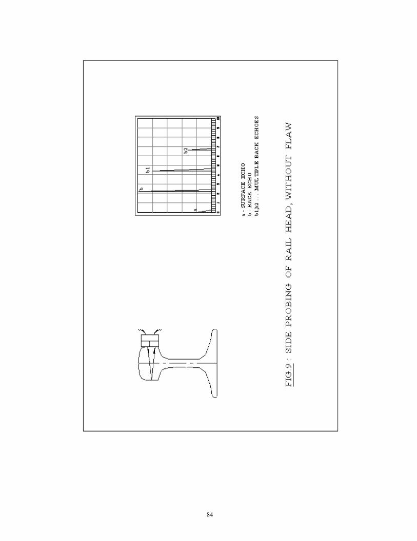
84
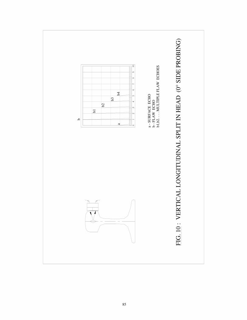
85
FIG
. 10
:
VE
RT
ICA
L L
ON
GIT
UD
INA
L S
PL
IT I
N H
EA
D (0
° S
IDE
PR
OB
ING
)
a -
SU
RF
AC
E E
CH
Ob
- F
LA
W E
CH
Ob
1,b
2.
. . .
MU
LT
IPL
E F
LA
W E
CH
OE
S
31
02
910
45
67
8
b2
b1
a
b
b3
b4
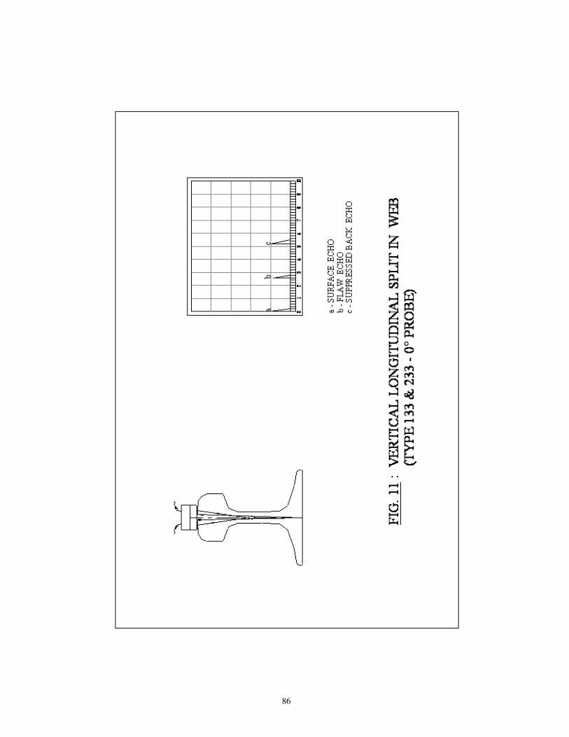
86
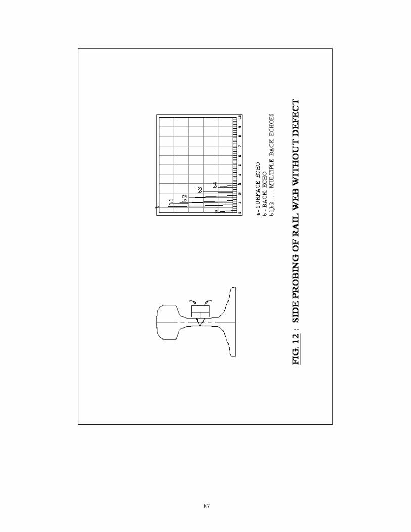
87
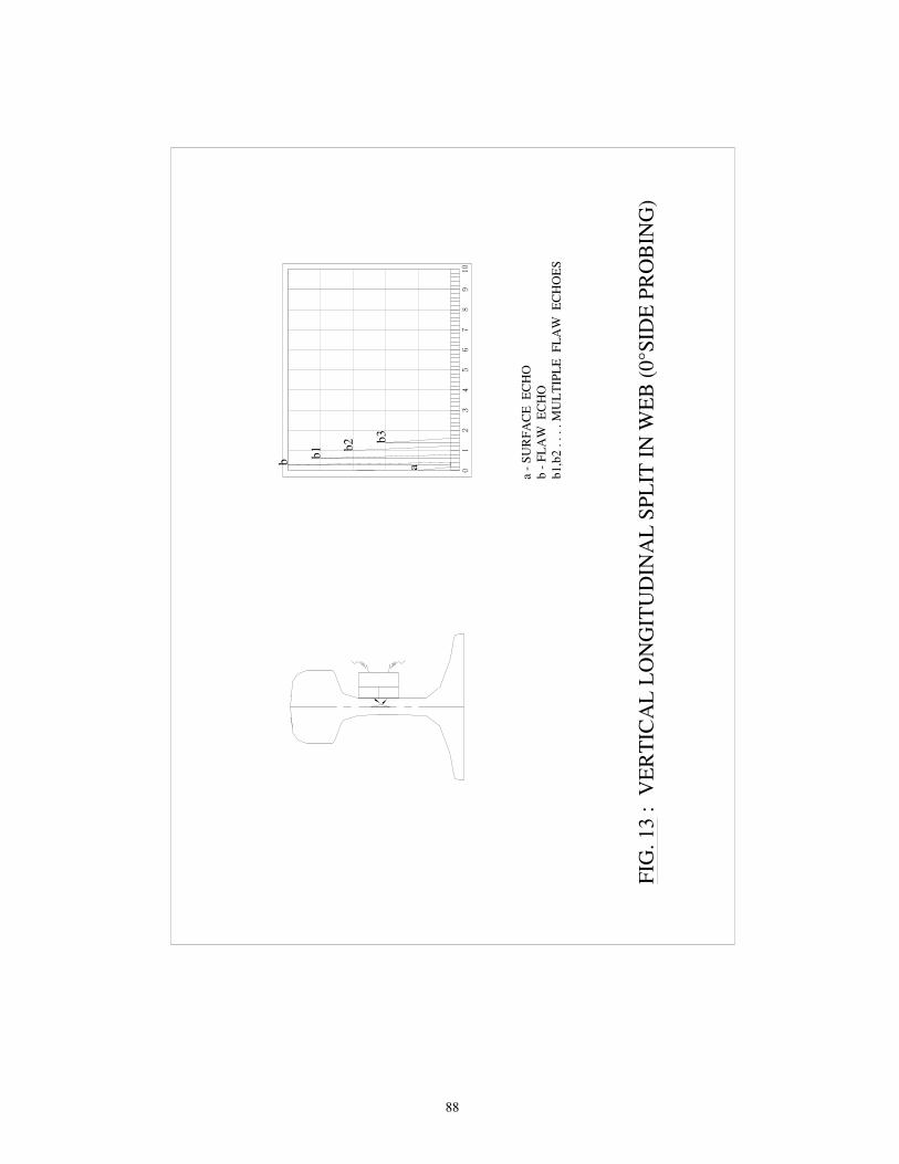
88
FIG
. 13
:
VE
RT
ICA
L L
ON
GIT
UD
INA
L S
PL
IT I
N W
EB
(0°S
IDE
PR
OB
ING
)
a -
SU
RF
AC
E E
CH
O
b -
FL
AW
E
CH
Ob
1,b
2 .
. .
. M
UL
TIP
LE
F
LA
W
EC
HO
ES
10
23
45
67
b3
b2
b1
b
910
8
a

89
FIG
. 14
:
SE
GR
EG
AT
ION
(0°
PR
OB
E)
a -
SU
RF
AC
E E
CH
Ob
- F
LA
W
EC
HO
(G
RA
SS
Y P
EA
K P
AT
TE
RN
)
54
32
01
10
98
76
a
b

90
BO
LT
H
OL
E
WIT
HO
UT
C
RA
CK
(0
° P
RO
BE
)F
IG.
15
:
MO
VE
ME
NT
OF
PR
OB
E
a -
SU
RF
AC
E E
CH
Ob
- B
OL
T H
OL
E E
CH
O
10
23
45
10
23
45
10
23
45
10
23
45
a
910
910
910
910
67
67
67
67
8888
b
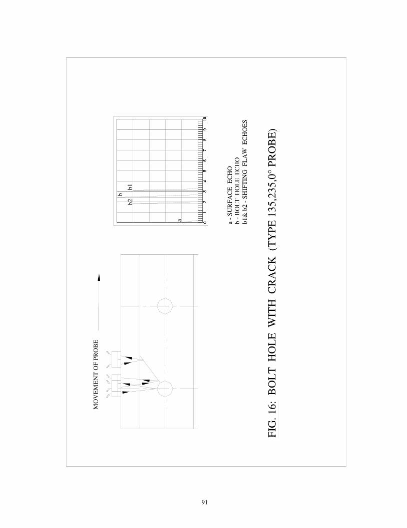
91
BO
LT
H
OL
E
WIT
H
CR
AC
K
(TY
PE
13
5,2
35
,0°
PR
OB
E)
FIG
. 16
:
MO
VE
ME
NT
OF
PR
OB
E
a a -
SU
RF
AC
E
EC
HO
b -
BO
LT
H
OL
E E
CH
Ob
1&
b2 -
SH
IFT
ING
F
LA
W E
CH
OE
S
88887
65
43
20
17
65
43
20
17
65
43
20
17
65
43
20
110
910
910
910
9
b1
b
b2

92
b -
F
LA
W E
CH
O A
T M
AX
IMU
M A
MP
LIT
UD
Eb
1 -
FL
AW
E
CH
O S
TA
RT
S A
PP
EA
RIN
G F
RO
M H
ER
Eb
2 -
FL
AW
E
CH
O V
AN
ISH
ES
HE
RE
.
FIG
.17
: T
RA
NS
VE
RS
E D
EF
EC
T (
TY
PE
111,
21
1 7
0°,
2 M
Hz,
FO
RW
AR
D P
RO
BE
)
45
61
02
3
b2
78
910
b1
MO
VE
ME
NT
OF
PR
OB
E
BF
b
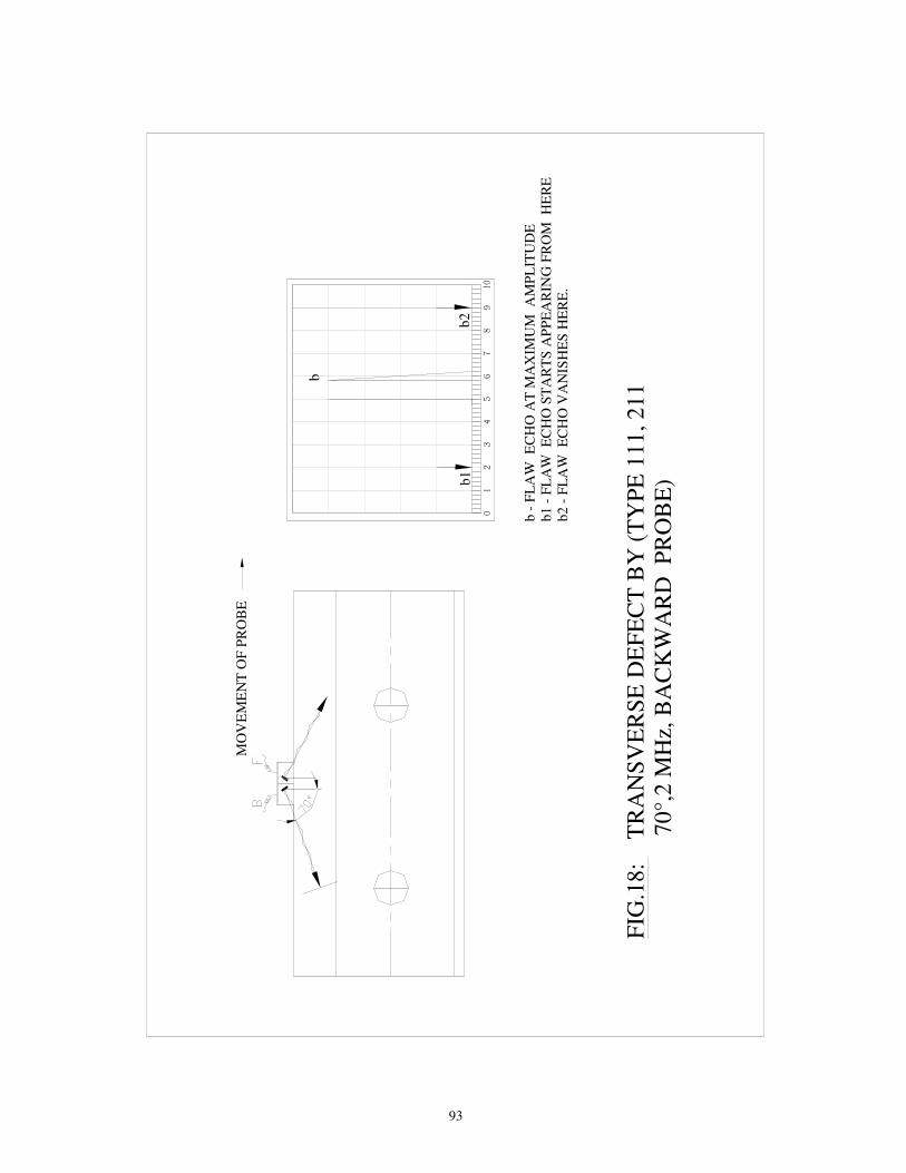
93
b -
FL
AW
E
CH
O A
T M
AX
IMU
M A
MP
LIT
UD
Eb
1 -
FL
AW
E
CH
O S
TA
RT
S A
PP
EA
RIN
G F
RO
M
HE
RE
b2 -
FL
AW
E
CH
O V
AN
ISH
ES
HE
RE
.
FIG
.18
: T
RA
NS
VE
RS
E D
EF
EC
T B
Y (
TY
PE
111
, 21
1 7
0°,
2 M
Hz,
BA
CK
WA
RD
P
RO
BE
)b1
20
1
b2
310
98
76
54
MO
VE
ME
NT
OF
PR
OB
E
b
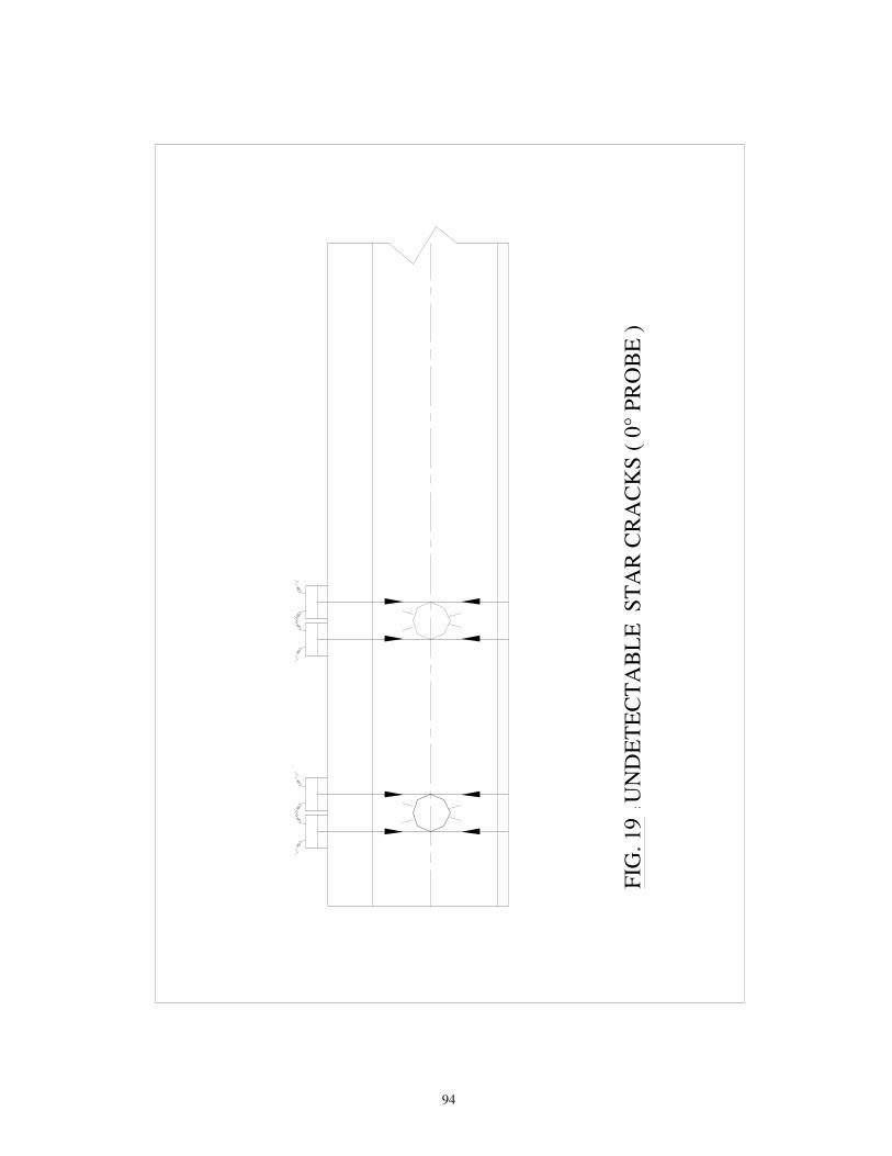
94
FIG
. 1
9 :
UN
DE
TE
CT
AB
LE
S
TA
R C
RA
CK
S (
0°
PR
OB
E )

95
3 m
m H
OL
E A
T T
HE
MID
DL
E
OF
TH
E F
LA
NG
E T
HR
OU
GH
T
HE
WE
LD
.
ST
AN
DA
RD
A.T
. W
EL
DE
D R
AIL
PIE
CE
WIT
H A
RT
IFIC
IAL
F
LA
WS
FO
R S
EN
SIT
IVIT
Y S
ET
TIN
G O
F U
LT
RA
SO
NIC
E
QU
IPM
EN
T T
O E
XA
MIN
E A
.T. W
EL
DS
FIG
. 20(a
) :
NO
TE
:- A
LL
DIM
EN
SIO
NS
AR
E I
N M
ILL
IME
TE
RS
.
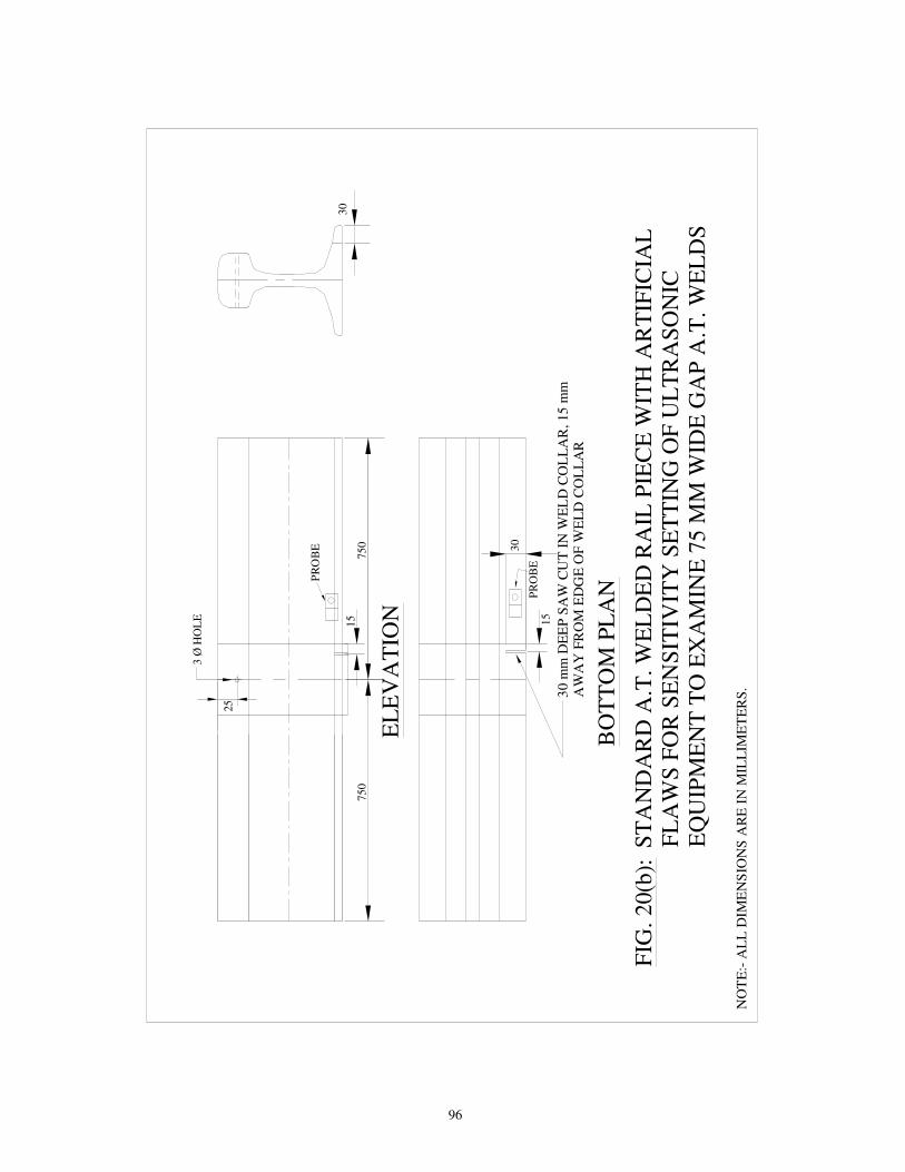
96
30
mm
DE
EP
SA
W C
UT
IN
WE
LD
CO
LL
AR
, 1
5 m
m
AW
AY
FR
OM
ED
GE
OF
WE
LD
CO
LL
AR
FIG
. 2
0(b
):
NO
TE
:- A
LL
DIM
EN
SIO
NS
AR
E I
N M
ILL
IME
TE
RS
.
BO
TT
OM
PL
AN
ST
AN
DA
RD
A.T
. W
EL
DE
D R
AIL
PIE
CE
WIT
H A
RT
IFIC
IAL
F
LA
WS
FO
R S
EN
SIT
IVIT
Y S
ET
TIN
G O
F U
LT
RA
SO
NIC
E
QU
IPM
EN
T T
O E
XA
MIN
E 7
5 M
M W
IDE
GA
P A
.T.
WE
LD
S
EL
EV
AT
ION
30
25
75
07
50
30
15
15
3 Ø
HO
LE
PR
OB
E
PR
OB
E
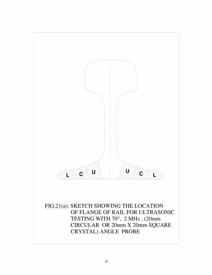
97
FIG.21(a): SKETCH SHOWING THE LOCATION OF FLANGE OF RAIL FOR ULTRASONIC TESTING WITH 70°, 2 MHz , (20mm CIRCULAR OR 20mm X 20mm SQUARE CRYSTAL) ANGLE PROBE
L C U CU
L

98
FIG. 21(b): TESTING OF BOTTOM FLANGE OF A.T.
WELDS USING 70° AND 45° PROBES
S
H70°
45°
H
A.T.WELD
70°
S
S
A.T.WELD
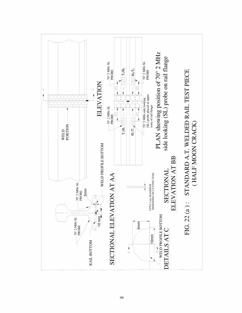
99
WE
LD
P
OR
TIO
N
10
mm
FIG
. 2
2 (
a )
:
ST
AN
DA
RD
A.T
. W
EL
DE
D R
AIL
TE
ST
PIE
CE
(
HA
LF
MO
ON
CR
AC
K)
5m
m
10
mm
UP
TO
2 m
m M
AX
IMU
M D
EP
EN
DIN
G O
N C
UT
TIN
G T
OO
L
DE
TA
ILS
AT
C
5m
m
RA
IL B
OT
TO
M
WE
LD
PR
OF
ILE
BO
TT
OM
WE
LD
PR
OF
ILE
BO
TT
OM
SE
CT
ION
AL
EL
EV
AT
ION
AT
AA
SE
CT
ION
AL
EL
EV
AT
ION
AT
BB
PL
AN
sh
ow
ing
po
siti
on
of
70
° 2 M
Hz
sid
e lo
ok
ing
(S
L)
pro
be
on
rai
l fl
ang
e
70
° 2
MH
z S
L
PR
OB
E
70
° 2
MH
z S
L
PR
OB
E
70
° 2
MH
z si
de
loo
kin
g
(SL
) p
rob
e p
lace
d a
t u
pp
er
zon
e o
f ra
il f
lan
ge
70
° 2
MH
z S
L
PR
OB
E
70
° 2
MH
z S
L
PR
OB
E
70
° 2
MH
z S
L
PR
OB
E
EL
EV
AT
ION
T1/R
1T
2/R
2
R1/T
1R
2/T
2

100
Fig.22(b): Sensitivity setting using 450 tandem probe
Fig. 22(c) : AT weld testing using 450 tandem probe
TX D RX
Flaw
Tx
Old fig 22 C

Annexure-1 B
<llnt re lire d v.eld (DATUM LINE)
I HEIGHT OF RAIL--j Tx /�l
R.(
- -- I
r-,/_J
_ , _L__===,-=-1--- �g. }
·- - - -:1 �
.,, - - - --
-- :l I -:-·-.,,-
I I. '.
FLAW-
Fig. 22 (c): AT Weld Testing using 45° tandem probe
Fig. 22(c)
6
New fig 22C CsNo.3 Aug-2016.
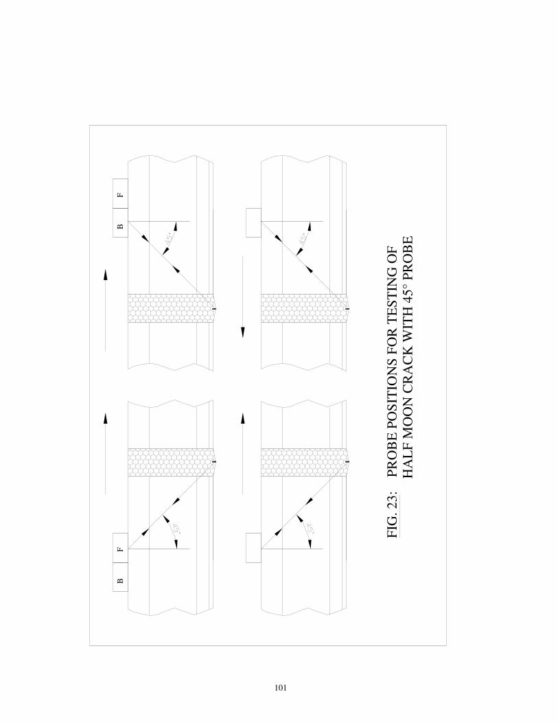
101
FIG
. 2
3:
P
RO
BE
PO
SIT
ION
S F
OR
TE
ST
ING
OF
H
AL
F M
OO
N C
RA
CK
WIT
H 4
5°
PR
OB
E
BF
FB

102
FIG.24 (a): POSITION OF 45° ANGLE PROBES AND BEAM PATH FOR VARIOUS FLAW LOCATIONS WHEN EXAMINING THE HEAD OF G.P. & F.B. WELDS
DETERMINING FLAW LOCATION HORIZONTAL
R T
FLAW ON LEFT HAND SIDE
FLAW IN MIDDLE
FLAW ON RIGHT HAND SIDE
RT
DETERMINING FLAW LOCATION VERTICAL
(FOR CRACKS IN RAIL HEAD TOP PORTION)
(FOR CRACKS IN MIDDLE ZONE OF RAIL HEAD)
(FOR CRACKS TOWARDS BOTTOM OF RAIL HEAD)
NOTE:- ALL DIMENSIONS ARE IN MILLIMETERS. TEST RANGE 165mmSW
FBW/GPW
R T
CALIBRATION AND SENSITIVITY SETTING (USING 45° PROBE) ON STANDARD RAIL PIECE
N.A.
250 250500
250
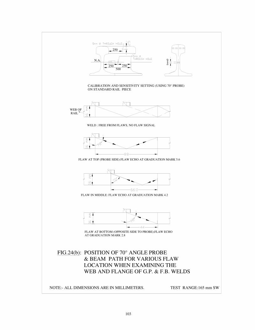
103
NOTE:- ALL DIMENSIONS ARE IN MILLIMETERS. TEST RANGE:165 mm SW
FLAW AT BOTTOM (OPPOSITE SIDE TO PROBE);FLAW ECHO AT GRADUATION MARK 2.8
FLAW IN MIDDLE: FLAW ECHO AT GRADUATION MARK 4.2
FLAW AT TOP (PROBE SIDE):FLAW ECHO AT GRADUATION MARK 5.6
WELD : FREE FROM FLAWS, NO FLAW SIGNAL
FIG.24(b): POSITION OF 70° ANGLE PROBE & BEAM PATH FOR VARIOUS FLAW LOCATION WHEN EXAMINING THE WEB AND FLANGE OF G.P. & F.B. WELDS
WEB OF RAIL
5m
mØ
CALIBRATION AND SENSITIVITY SETTING (USING 70° PROBE) ON STANDARD RAIL PIECE
N.A.
250 250500
250
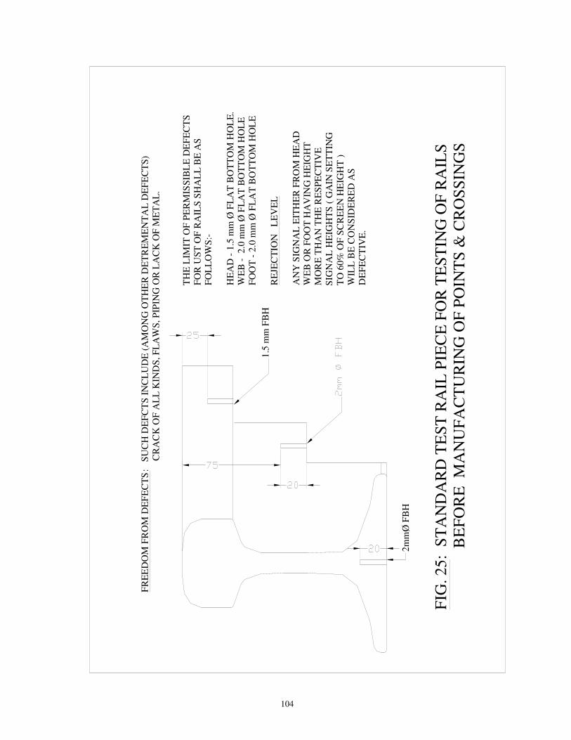
104
TH
E L
IMIT
OF
PE
RM
ISS
IBL
E D
EF
EC
TS
FO
R U
ST
OF
RA
ILS
SH
AL
L B
E A
SF
OL
LO
WS
:-
HE
AD
- 1
.5 m
m Ø
FL
AT
BO
TT
OM
HO
LE
.W
EB
-
2.0
mm
Ø F
LA
T B
OT
TO
M H
OL
EF
OO
T -
2.0
mm
Ø F
LA
T B
OT
TO
M H
OL
E
RE
JEC
TIO
N L
EV
EL
AN
Y S
IGN
AL
EIT
HE
R F
RO
M H
EA
D
WE
B O
R F
OO
T H
AV
ING
HE
IGH
TM
OR
E T
HA
N T
HE
RE
SP
EC
TIV
E
SIG
NA
L H
EIG
HT
S (
GA
IN S
ET
TIN
G
TO
60
% O
F S
CR
EE
N H
EIG
HT
)W
ILL
BE
CO
NS
IDE
RE
D A
S
DE
FE
CT
IVE
.
1.5
mm
FB
H
2m
mØ
FB
H
FR
EE
DO
M F
RO
M D
EF
EC
TS
:
SU
CH
DE
FC
TS
IN
CL
UD
E (
AM
ON
G O
TH
ER
DE
TR
EM
EN
TA
L D
EF
EC
TS
)
CR
AC
K O
F A
LL
KIN
DS
, F
LA
WS
, P
IPIN
G O
R L
AC
K O
F M
ET
AL
.
FIG
. 2
5:
ST
AN
DA
RD
TE
ST
RA
IL P
IEC
E F
OR
TE
ST
ING
OF
RA
ILS
BE
FO
RE
M
AN
UF
AC
TU
RIN
G O
F P
OIN
TS
& C
RO
SS
ING
S
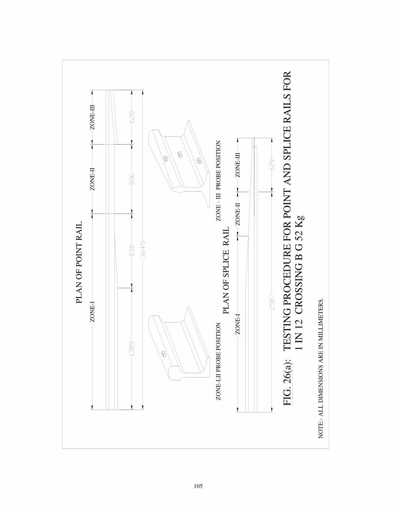
105
PL
AN
OF
PO
INT
RA
IL
PL
AN
OF
SP
LIC
E R
AIL
FIG
. 2
6(a
):
TE
ST
ING
PR
OC
ED
UR
E F
OR
PO
INT
AN
D S
PL
ICE
RA
ILS
FO
R
1 I
N 1
2
CR
OS
SIN
G B
G 5
2 K
g
ZO
NE
-IZ
ON
E-I
IZ
ON
E-I
II
ZO
NE
-III
ZO
NE
-II
ZO
NE
-I
NO
TE
:- A
LL
DIM
EN
SIO
NS
AR
E I
N M
ILL
IME
TE
RS
.
ZO
NE
-I,I
I P
RO
BE
PO
SIT
ION
ZO
NE
- I
II
PR
OB
E P
OS
ITIO
N

106
FIG
. 26(b
) :
ST
AN
DA
RD
TE
ST
PIE
CE
(S
EJ
ST
OC
K R
AIL
)
NO
TE
:- A
LL
DIM
EN
SIO
NS
AR
E IN
M
ILL
IME
TE
RS
.
PL
AN
EL
EV
AT
ION
5 Ø
TH
RO
UG
H H
OL
E A
T
DE
PT
H O
F 2
5 m
m I
N R
AIL
HE
AD
LO
CA
TIO
N 'A
'
LO
CA
TIO
N 'B
'
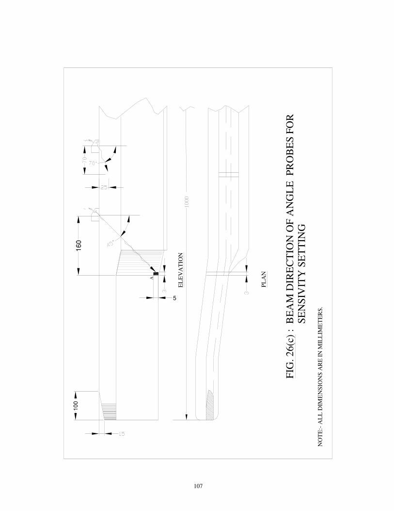
107
10
0
EL
EV
AT
ION
PL
AN
A
5
16
0
FIG
. 2
6(c
) :
BE
AM
DIR
EC
TIO
N O
F A
NG
LE
P
RO
BE
S F
OR
S
EN
SIV
ITY
SE
TT
ING
NO
TE
:- A
LL
DIM
EN
SIO
NS
AR
E I
N M
ILL
IME
TE
RS
.

108
1
0°4MHzDOUBLECRYSTAL
1. LONGITUDINAL HORIZONTAL DEFECTS IN HEAD WEB AND FOOT2.STAR CRACK IN WEB ( BOLT HOLE)
1. HALF MOON DEFECTS IN A.T.WELDED JOINTS IN FLANGE LOCATION BELOW WEB-FOOT JUNCTION
FIG. 27 : DETAIL OF PROBES USED FOR TESTING OF RAIL AND WELDS
1. TRANSVERSE DEFECTS IN RAIL HEAD
1. TRANSVERSE DEFECTS IN HEAD PORTIONS OF F.B. AND G.P.WELDED JOINT2. HALF MOON DEFECTS IN A.T.WELDS BELOW WEB-FOOT JUNCTION
1. DEFECTS OF A.T.WELDED JOINTS IN FLANGE LOCATION
570°2 MHzSIDE LOOKING PROBE (SLP)
T+R
70°FORWARD(F) ANDBACK WARD(B) 2MHzSINGLE CRYSTAL
470° 2 MHz, (20mm CIRCULAR OR 20mm X 20mm SQUARE CRYSTAL) SINGLE CRYSTAL
3
45°2MHzSINGLECRYSTAL
T+R
B
T+R
F
2
T+R T+R
APPLICATIONSl.No.
PROBE ANGLE
T R
BEAM PATH
20°

109
RT
d
2 x
d
20mm
PLA
N
ELE
VA
TIO
N
FIG
. 28
: S
en
sit
ivit
y s
ett
ing
/Te
sti
ng
wit
h 4
5°
pro
be
us
ing
Te
st
Rig
(f
or
loc
ati
on
s h
avin
g
sca
bs
/wh
ee
l b
urn
s)
PR
OB
ES
TE
ST
RIG
TE
ST
RIG
PR
OB
ES
SC
AB
/ W
HE
EL
BU
RN
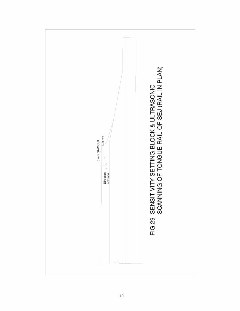
110
FIG
.29
SE
NS
ITIV
ITY
SE
TT
ING
BL
OC
K &
ULT
RA
SO
NIC
SC
AN
NIN
G O
F T
ON
GU
E R
AIL
OF
SE
J (
RA
IL IN
PLA
N)
5 m
m S
AW
CU
T
Dir
ectio
n
of P
robe
5 m
m

111
FIG.30: Typical signal pattern of bunch of moving signals for AT welds
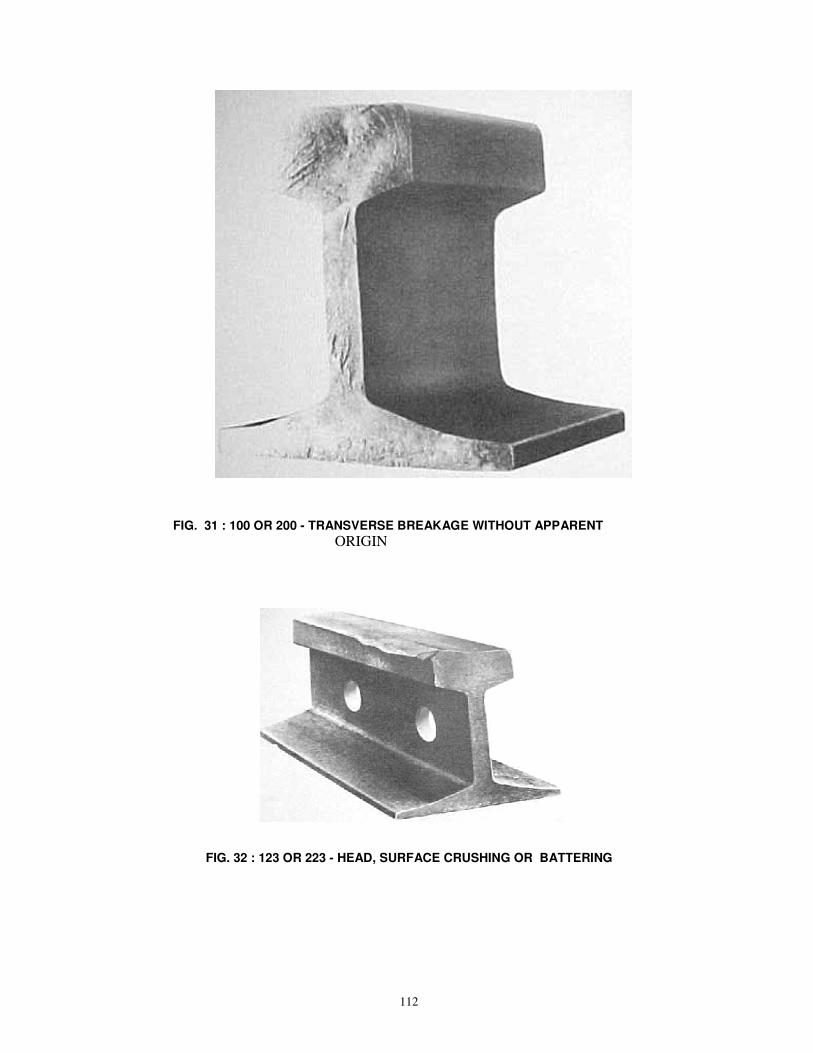
112
FIG. 31 : 100 OR 200 - TRANSVERSE BREAKAGE WITHOUT APPARENT
ORIGIN
FIG. 32 : 123 OR 223 - HEAD, SURFACE CRUSHING OR BATTERING

113
FIG. 33 : 111 OR 211 - INTERNAL FLAW IN HEAD , TRANSVERSE BREAKAGE
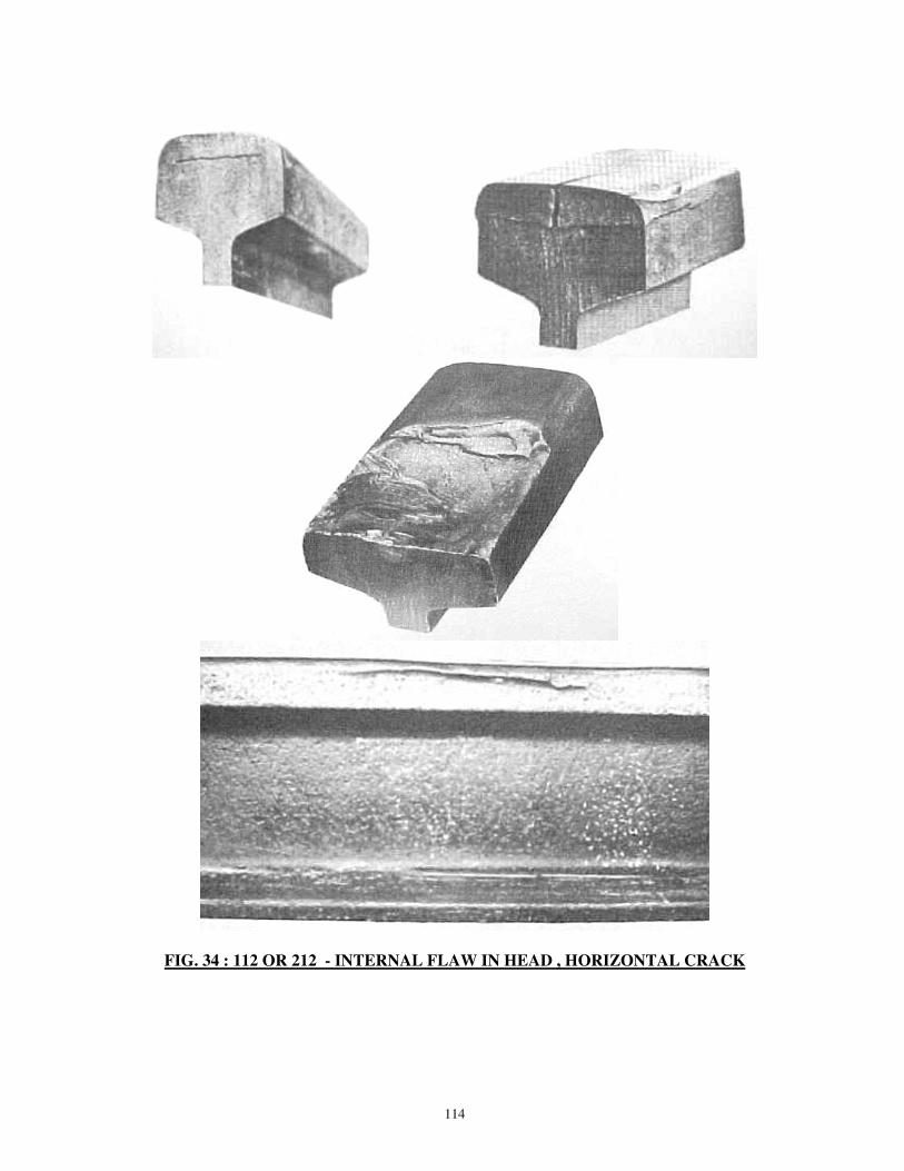
114
FIG. 34 : 112 OR 212 - INTERNAL FLAW IN HEAD , HORIZONTAL CRACK

115
113
213
FIG. 35 : 113 OR 213 - INTERNAL FLAW IN HEAD , VERTICAL
LONGITUDINAL SPLIT
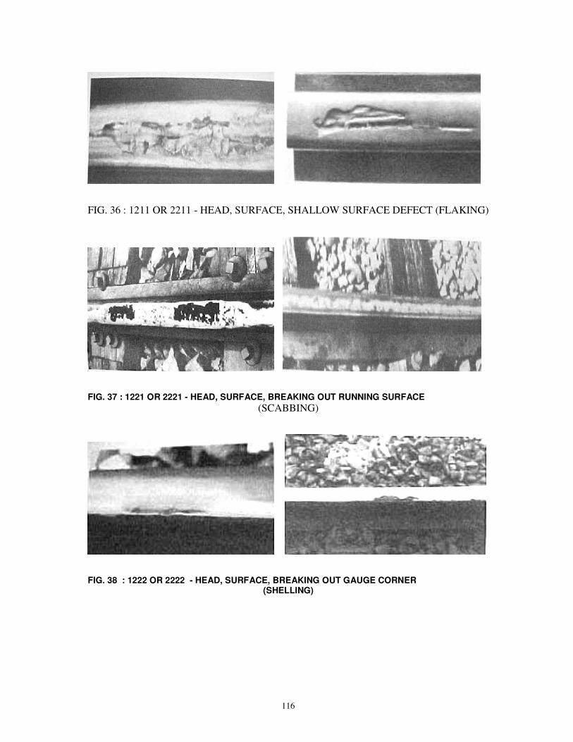
116
FIG. 36 : 1211 OR 2211 - HEAD, SURFACE, SHALLOW SURFACE DEFECT (FLAKING)
FIG. 37 : 1221 OR 2221 - HEAD, SURFACE, BREAKING OUT RUNNING SURFACE
(SCABBING)
FIG. 38 : 1222 OR 2222 - HEAD, SURFACE, BREAKING OUT GAUGE CORNER (SHELLING)
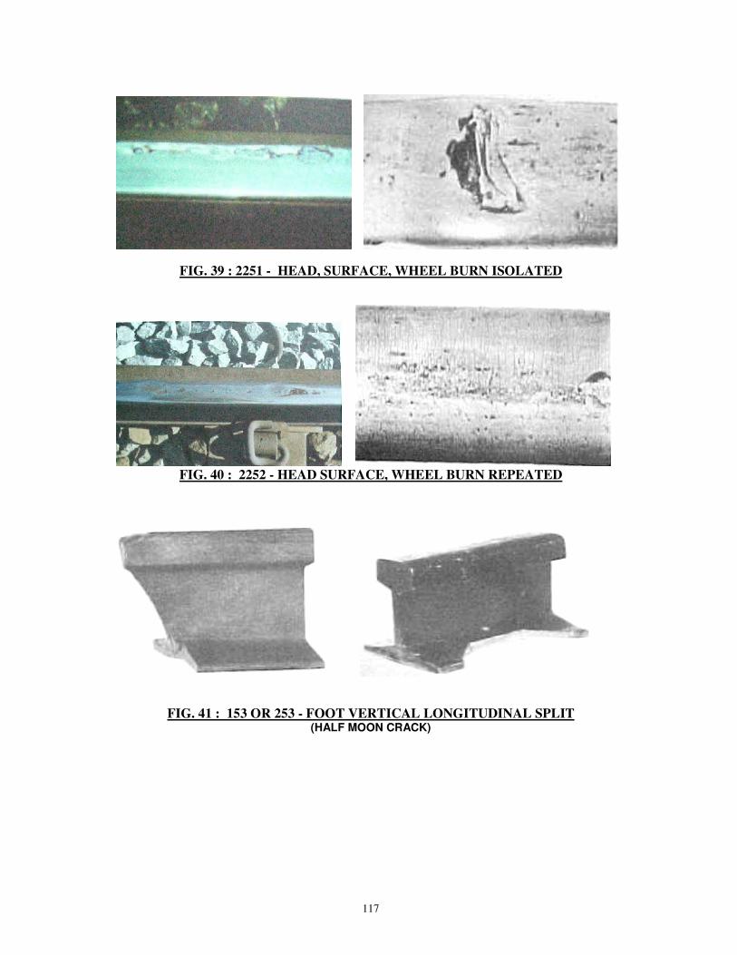
117
FIG. 39 : 2251 - HEAD, SURFACE, WHEEL BURN ISOLATED
FIG. 40 : 2252 - HEAD SURFACE, WHEEL BURN REPEATED
FIG. 41 : 153 OR 253 - FOOT VERTICAL LONGITUDINAL SPLIT
(HALF MOON CRACK)

118
FIG. 42 : 1321 OR 2321 - WEB , HORIZONTAL CRACK, AT TOP FILLET RADIUS

119
1322 1322
1322
2322 2322
FIG. 43 : 1322 OR 2322 - WEB, HORIZONTAL CRACK AT BOTTOM
FILLET RADIUS

120
FIG. 44 : 133 OR 233 - WEB, VERTIVAL LONGITUDINAL SPLITTING (PIPING)
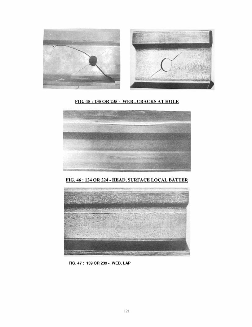
121
FIG. 45 : 135 OR 235 - WEB , CRACKS AT HOLE
FIG. 46 : 124 OR 224 - HEAD, SURFACE LOCAL BATTER
FIG. 47 : 139 OR 239 - WEB, LAP

122
FIG. 48 : 301 - DAMAGE TO RAIL BY BRUSHING OR ARCING
FIG. 49 : 302 -DAMAGE TO RAIL BY BAD MACHINING , DRILLING OR FLAME CUTTING
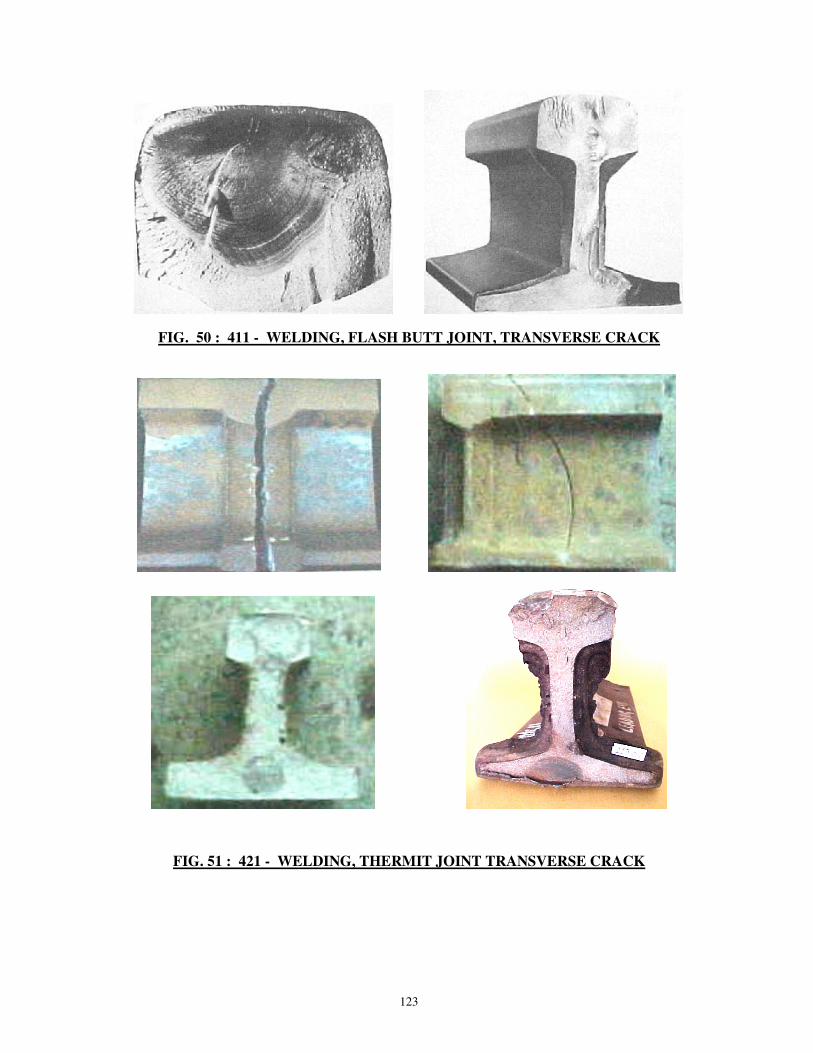
123
FIG. 50 : 411 - WELDING, FLASH BUTT JOINT, TRANSVERSE CRACK
FIG. 51 : 421 - WELDING, THERMIT JOINT TRANSVERSE CRACK

124
FIG. 52 : 422 - WELDING, THERMIT JOINT HORIZONTAL CRACK
FIG. 53 : 431 - WELDING, ELECTRIC ARC JOINT TRANSVERSE CRACK
FIG. 54 : 471 - WELDING, BUILDING UP TRANSVERSE CRACKING OF HEAD ACROSS THE BUILT UP PORTION
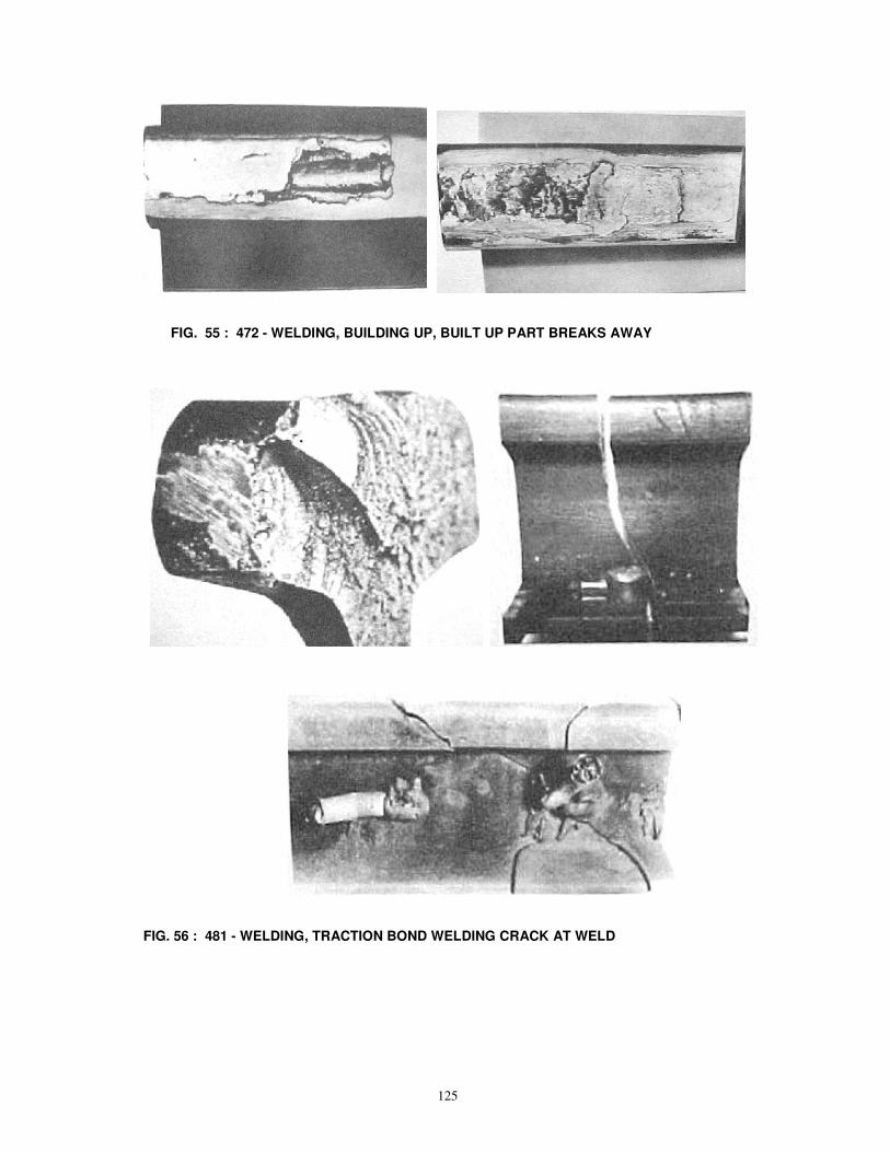
125
FIG. 55 : 472 - WELDING, BUILDING UP, BUILT UP PART BREAKS AWAY
FIG. 56 : 481 - WELDING, TRACTION BOND WELDING CRACK AT WELD
![e/;izns'k O;kolkf;d ijh{kk e.My] Hkksikyimages.jagran.com/jagranjosh/mp-prt-advertisement-2012.pdfe/;izns'k O;kolkf;d ijh{kk e.My] Hkksiky ... gSA](https://img.pdfslide.us/doc/110x75/5e77083c213dc913a96eb985/eiznsk-okolkfd-ijhkk-emy-eiznsk-okolkfd-ijhkk-emy-hkksiky-gsa.jpg)


![Presentation1 › PDF › WareHouse.pdf · 10- ¼v½ os;jgkml gsrq & lQy fufonkdrkZ ds vuqeksnu gsrq lfefr }kjk v/;{k] vkS|ksfxd dsUnz fodkl fuxe Hkksiky ds le{k vuq’kalk izLrqr](https://img.pdfslide.us/doc/110x75/5f0f52917e708231d443968b/a-pdf-a-warehousepdf-10-v-osjgkml-gsrq-lqy-fufonkdrkz-ds-vuqeksnu.jpg)


![mÙkjk[k.M yksd lsok vk;ksx] - Uttarakhand Public Service · PDF file · 2016-08-222 mi;qDr vH;fFkZ;ksa ds p;u gsrq lfEefyr jkT; voj v/khuLFk lsok ijh{kk&2016 ds vUrxZr fjDr dqy 184](https://img.pdfslide.us/doc/110x75/5aaff0bf7f8b9a25088e1b20/mkjkkm-yksd-lsok-vkksx-uttarakhand-public-service-miqdr-vhffkzksa-ds.jpg)
![Ihykgbl evgZyaZibkdZ - Moscow Center for Continuous ... · Ihykgbl_evgZyaZibkdZ >hihegbl_evgZy h[jZah\Zl_evgZy ijh]jZffZ ©Eh]bdZ \ fZl_fZlbd_ª y\ey_lky ijh]jZffhc _ kl_kl\_gghgZmqghc](https://img.pdfslide.us/doc/110x75/5ee22900ad6a402d666cc2c3/ihykgbl-evgzyazibkdz-moscow-center-for-continuous-ihykgblevgzyazibkdz-hihegblevgzy.jpg)


![1 H[eZklv ijbf g gby · KI 133.13330.2012 1 3.18 ljm[hklhcdb ijh\h^gh]h \_sZgby : Mkljhckl\h ^ey ih^\_rb\Zgby gZ baheylhjZo k ihfhsvx \\yahqghc ijh\hehdb jZaebqguo lbih\ ijh\h^h\](https://img.pdfslide.us/doc/110x75/5ed920e66714ca7f4769334a/1-hezklv-ijbf-g-ki-133133302012-1-318-ljmhklhcdb-ijhhghh-szgby-mkljhcklh.jpg)
![lewg ‘x’ ,oa - KopyKitab€¦ · lewg ‘x’ ,oa ‘? ... œ`ksu # 0522–4109080 ... v˙;fFkZ;kÍ d`k p;u Ldz`hfuax ijh{kk] f¥f[r ijh{kk] O;kogkfjd` ijh{kk ,oa](https://img.pdfslide.us/doc/110x75/5ae654387f8b9a3d3b8d0f63/lewg-x-oa-kopykitab-lewg-x-oa-oeksu-05224109080.jpg)

![ijh dlZo Mfguc]hjh^](https://img.pdfslide.us/doc/110x75/6178408b2d304375647d2cf7/ijh-dlzo-mfguchjh.jpg)
![Ijh]jZffZ ijZdlbdb](https://img.pdfslide.us/doc/110x75/6196e6399e4f683d7e750a00/ijhjzffz-ijzdlbdb.jpg)