Embed Size (px)
Citation preview
- 1 -
JRC/CRT GPS Module
Hardware Specification
This document specifies the electrical, mechanical, and behavioral characteristics of JRC/CRT GPS engine module.
Module:G597 Version: V1.0 Date: 2009-03-26
Drawn Checked Released

- 2 -
Revision History Revision Release date Issuer Change description G597 V1.0 2009-3-20 Creative
- 3 -
Contents 1 Description ...........................................................................................................- 1 -
2 Mechanical specifications.......................................................................................- 2 -
3 Electrical Specifications .........................................................................................- 3 -
4 Typical characteristics ............................................................................................- 4 -
5 Pin Definition........................................................................................................- 5 -
6 Reference PCB layout ............................................................................................- 7 -
7 Reference Design ..................................................................................................- 8 -
8 NMEA output Sentence ........................................................................................- 10 -
9 Supplier's Responsibility ......................................................................................- 13 -
10 Notice for handling ............................................................................................- 13 -
11 ESD handling precautions ...................................................................................- 15 -
- -
- 1 -
1 Description
This document specifies the electrical, mechanical and behavioral characteristics
of JRC/CRT GPS Module — G597.
The G597 is a GPS receiver module which providing the best solution with the
highest sensitivity and tracking performance in the world and also with the highest
position and speed accuracy in urban conditions.
The G597 GPS module uses the GPS solution with chipsets designed by JRC.
Inc,.
The G597 GPS module can supports up to 210 PRN channels, with 66 search
channels and 22 simutaneous tracking channels. It supports signal procession of L1
band signals such as GPS C/A and SBAS(including WAAS,EGNOS MSAS).With the
flexible software API and library ,customer can realize both autonomous navigation
solution and assisted GPS navigation solution to obtain fast TTFF and accurate
navigation performance even in harsh urban canyon or weak indoor signal
environment.
The G597 GPS module is the best choice for you to design for GPS related
products.
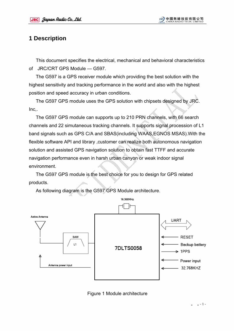
As following diagram is the G597 GPS Module architecture.
Figure 1 Module architecture
- -
- 2 -
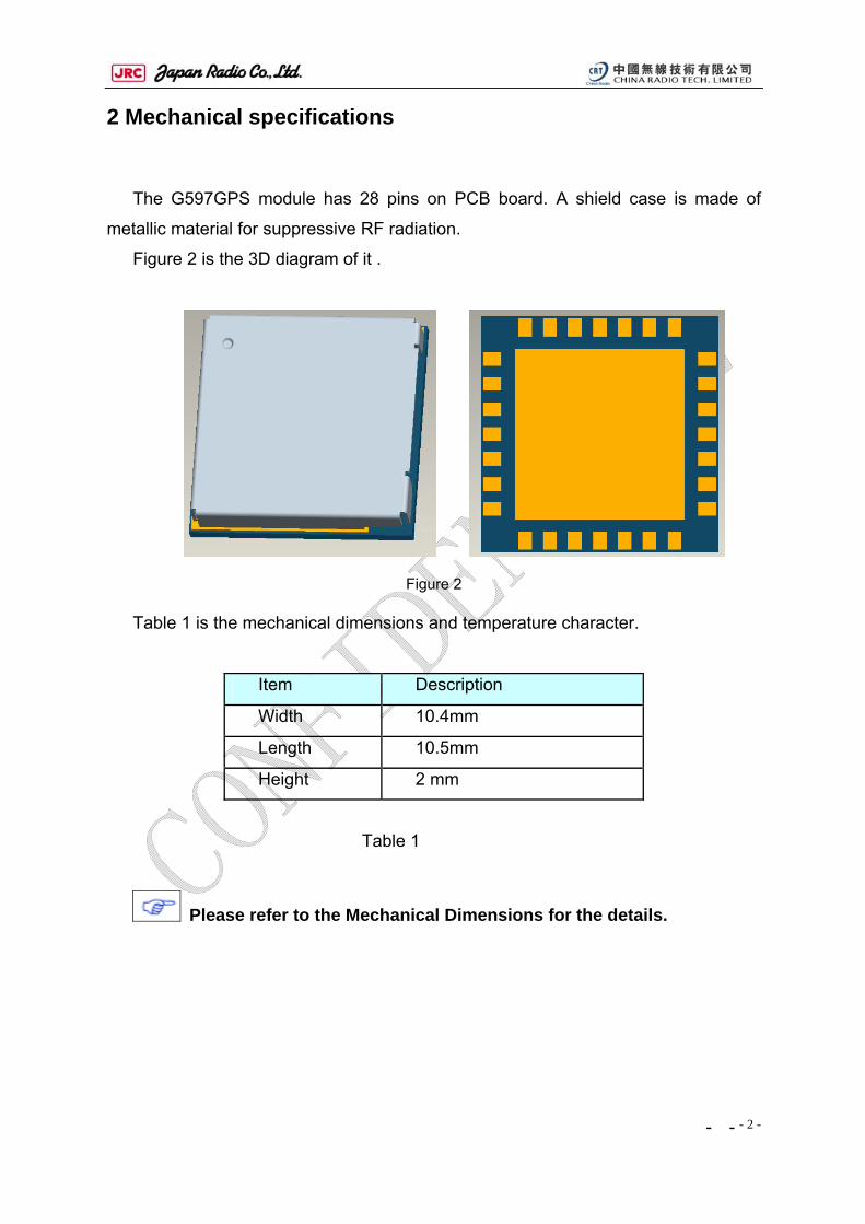
2 Mechanical specifications
The G597GPS module has 28 pins on PCB board. A shield case is made of
metallic material for suppressive RF radiation.
Figure 2 is the 3D diagram of it .
Figure 2
Table 1 is the mechanical dimensions and temperature character.
Item Description
Width 10.4mm
Length 10.5mm
Height 2 mm
Table 1
Please refer to the Mechanical Dimensions for the details.
- -
- 3 -
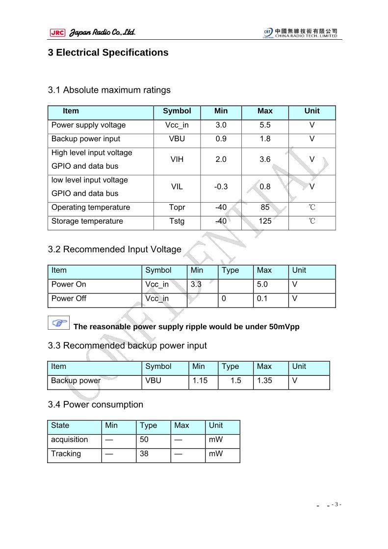
3 Electrical Specifications
3.1 Absolute maximum ratings
Item Symbol Min Max Unit
Power supply voltage Vcc_in 3.0 5.5 V
Backup power input VBU 0.9 1.8 V
High level input voltage
GPIO and data bus VIH 2.0 3.6 V
low level input voltage
GPIO and data bus VIL -0.3 0.8 V
Operating temperature Topr -40 85
Storage temperature Tstg -40 125
3.2 Recommended Input Voltage Item Symbol Min Type Max Unit
Power On Vcc_in 3.3 5.0 V
Power Off Vcc_in 0 0.1 V
The reasonable power supply ripple would be under 50mVpp 3.3 Recommended backup power input Item Symbol Min Type Max Unit
Backup power VBU 1.15 1.5 1.35 V
3.4 Power consumption State Min Type Max Unit
acquisition — 50 — mW
Tracking — 38 — mW
- -
- 4 -
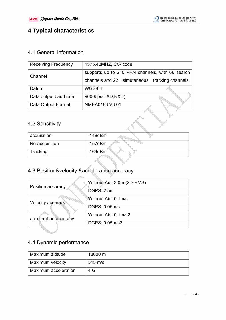
4 Typical characteristics
4.1 General information Receiving Frequency 1575.42MHZ, C/A code
Channel supports up to 210 PRN channels, with 66 search
channels and 22 simutaneous tracking channels
Datum WGS-84
Data output baud rate 9600bps(TXD,RXD)
Data Output Format NMEA0183 V3.01
4.2 Sensitivity acquisition -148dBm
Re-acquisition -157dBm
Tracking -164dBm
4.3 Position&velocity &acceleration accuracy
Without Aid: 3.0m (2D-RMS) Position accuracy
DGPS: 2.5m
Without Aid: 0.1m/s Velocity accuracy
DGPS: 0.05m/s
Without Aid: 0.1m/s2 acceleration accuracy
DGPS: 0.05m/s2
4.4 Dynamic performance Maximum altitude 18000 m
Maximum velocity 515 m/s
Maximum acceleration 4 G
- -
- 5 -
4.5 Time To First Fix Hot start <1.5 s
Warm start <34 s
Cold start <35 s (autonomous)
Re-acquisition time <1 s
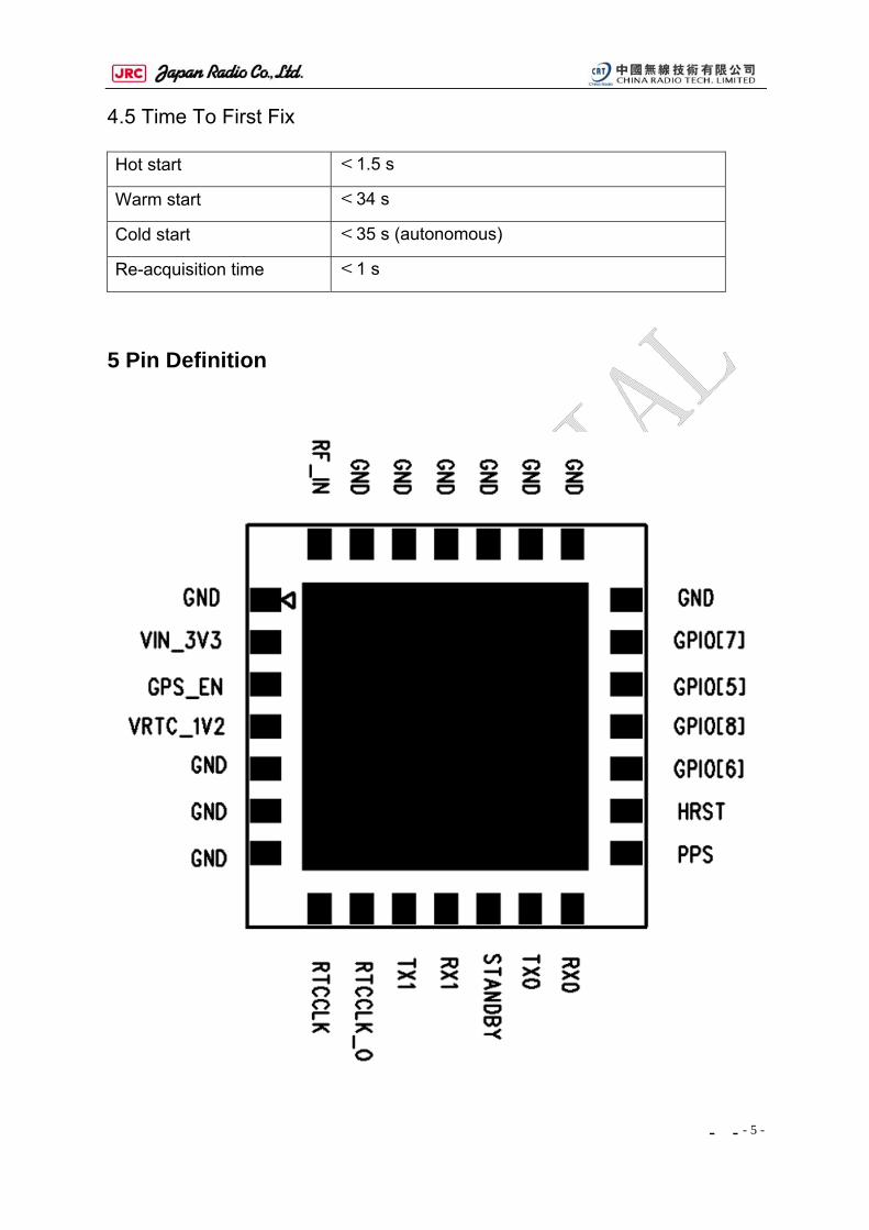
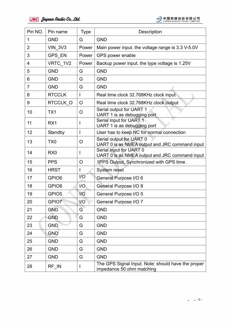
5 Pin Definition
- -
- 6 -
Pin NO. Pin name Type Description
1 GND G GND
2 VIN_3V3 Power Main power input. the voltage range is 3.3 V-5.0V
3 GPS_EN Power GPS power enable
4 VRTC_1V2 Power Backup power input. the type voltage is 1.25V
5 GND G GND
6 GND G GND
7 GND G GND
8 RTCCLK I Real time clock 32.768KHz clock input
9 RTCCLK_O O Real time clock 32.768KHz clock output
10 TX1 O Serial output for UART 1 UART 1 is as debugging port
11 RX1 I Serial input for UART 1 UART 1 is as debugging port
12 Standby I User has to keep NC for normal connection
13 TX0 O Serial output for UART 0 UART 0 is as NMEA output and JRC command input
14 RX0 I Serial input for UART 0 UART 0 is as NMEA output and JRC command input
15 PPS O 1PPS Output, Synchronized with GPS time .
16 HRST I System reset
17 GPIO6 I/O General Purpose I/O 6
18 GPIO8 I/O General Purpose I/O 8
19 GPIO5 I/O General Purpose I/O 5
20 GPIO7 I/O General Purpose I/O 7
21 GND G GND
22 GND G GND
23 GND G GND
24 GND G GND
25 GND G GND
26 GND G GND
27 GND G GND
28 RF_IN I The GPS Signal Input. Note: should have the proper impedance 50 ohm matching
- -
- 7 -
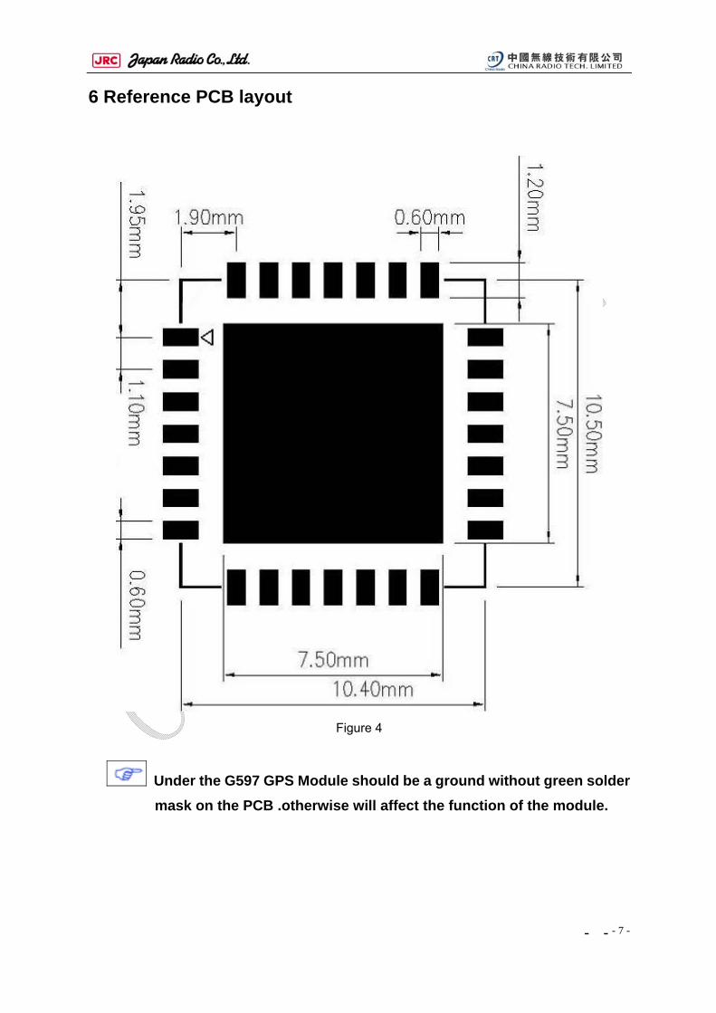
6 Reference PCB layout
Figure 4
Under the G597 GPS Module should be a ground without green solder mask on the PCB .otherwise will affect the function of the module.
- -
- 8 -
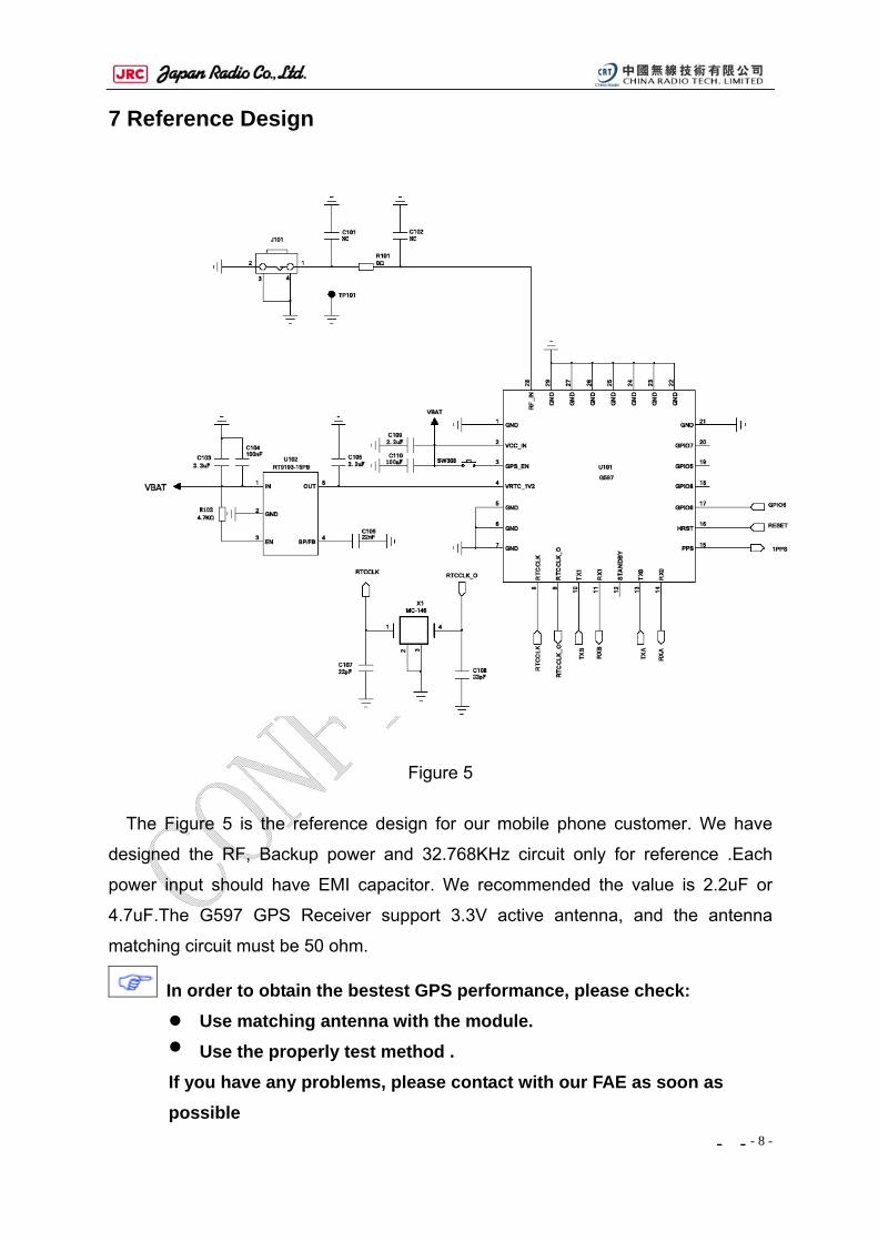
7 Reference Design
Figure 5
The Figure 5 is the reference design for our mobile phone customer. We have
designed the RF, Backup power and 32.768KHz circuit only for reference .Each
power input should have EMI capacitor. We recommended the value is 2.2uF or
4.7uF.The G597 GPS Receiver support 3.3V active antenna, and the antenna
matching circuit must be 50 ohm.
In order to obtain the bestest GPS performance, please check: Use matching antenna with the module. Use the properly test method .
If you have any problems, please contact with our FAE as soon as possible
- -
- 9 -
为了确保 GPS 模块的性能,请使用与模块匹配的天线,请确认测试方式是否合
理,如果还有其他的问题,请及时跟我们的 FAE 联系。
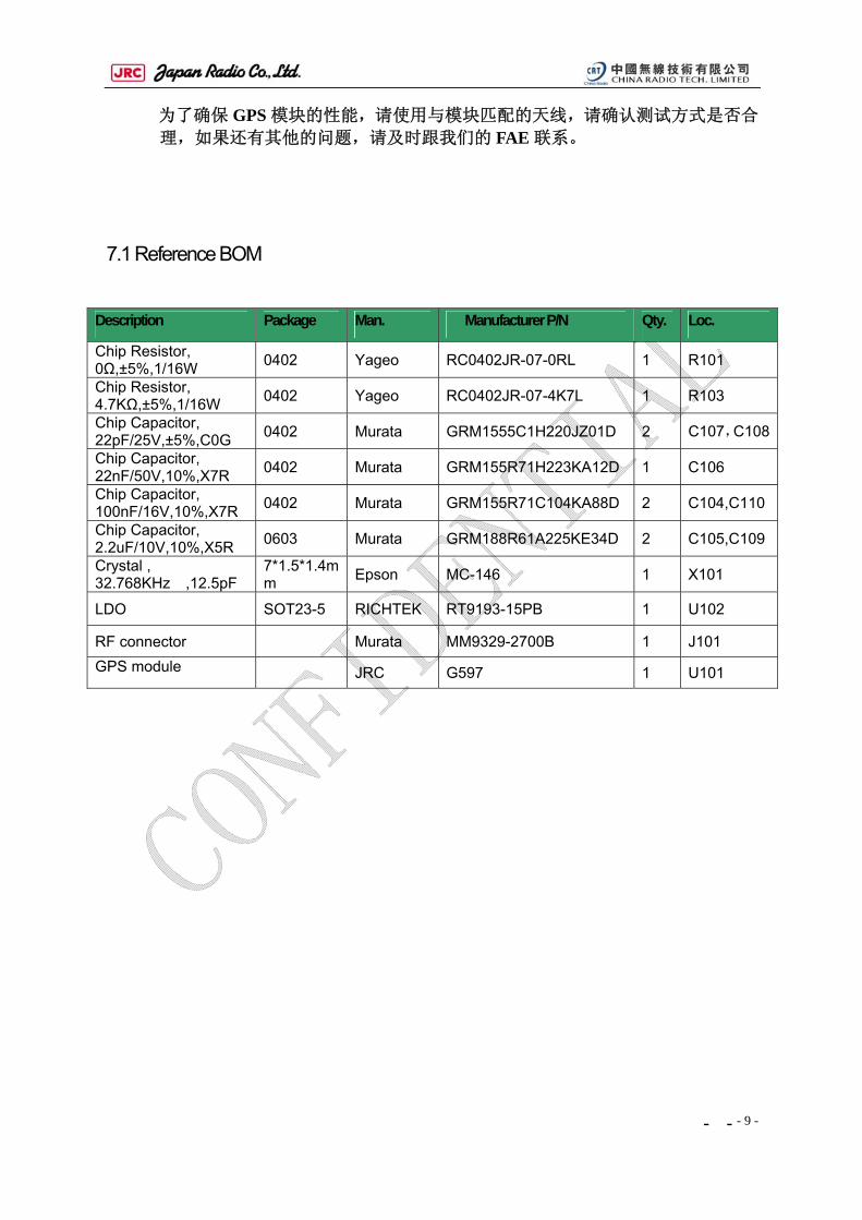
7.1 Reference BOM
Description Package Man. Manufacturer P/N Qty. Loc.
Chip Resistor, 0Ω,±5%,1/16W 0402 Yageo RC0402JR-07-0RL 1 R101
Chip Resistor, 4.7KΩ,±5%,1/16W 0402 Yageo RC0402JR-07-4K7L 1 R103
Chip Capacitor, 22pF/25V,±5%,C0G 0402 Murata GRM1555C1H220JZ01D 2 C107,C108
Chip Capacitor, 22nF/50V,10%,X7R 0402 Murata GRM155R71H223KA12D 1 C106
Chip Capacitor, 100nF/16V,10%,X7R 0402 Murata GRM155R71C104KA88D 2 C104,C110
Chip Capacitor, 2.2uF/10V,10%,X5R 0603 Murata GRM188R61A225KE34D 2 C105,C109
Crystal , 32.768KHz ,12.5pF
7*1.5*1.4mm Epson MC-146 1 X101
LDO SOT23-5 RICHTEK RT9193-15PB 1 U102
RF connector Murata MM9329-2700B 1 J101 GPS module JRC G597 1 U101
- -
- 10 -
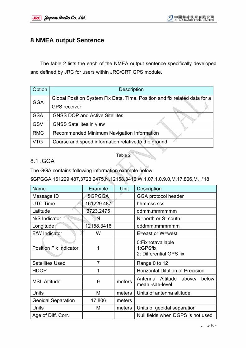
8 NMEA output Sentence
The table 2 lists the each of the NMEA output sentence specifically developed
and defined by JRC for users within JRC/CRT GPS module.
Option Description
GGA Global Position System Fix Data. Time. Position and fix related data for a
GPS receiver
GSA GNSS DOP and Active Sitellites
GSV GNSS Satellites in view
RMC Recommended Minimum Navigation Information
VTG Course and speed information relative to the ground
Table 2
8.1 .GGA The GGA contains following information example below:
$GPGGA,161229.487,3723.2475,N,12158.3416,W,1,07,1.0,9.0,M,17.806,M, ,*18
Name Example Unit Description Message ID $GPGGA GGA protocol header UTC Time 161229.487 hhmmss.sss Latitude 3723.2475 ddmm.mmmmmm N/S Indicator N N=north or S=south Longitude 12158.3416 dddmm.mmmmmm E/W Indicator W E=east or W=west
Position Fix Indicator 1 0:Fixnotavailable 1:GPSfix 2: Differential GPS fix
Satellites Used 7 Range 0 to 12 HDOP 1 Horizontal Dilution of Precision
MSL Altitude 9 meters Antenna Altitude above/ below mean -sae-level
Units M meters Units of antenna altitude Geoidal Separation 17.806 meters Units M meters Units of geoidal separation Age of Diff. Corr. Null fields when DGPS is not used
- -
- 11 -
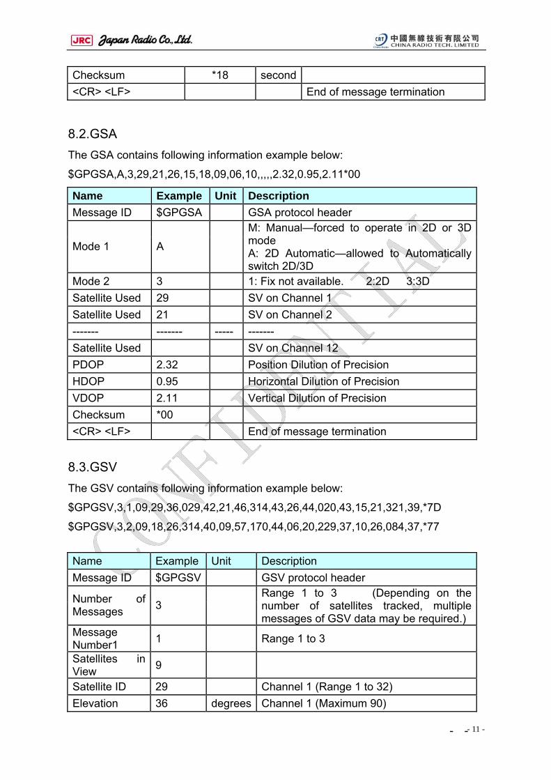
Checksum *18 second <CR> <LF> End of message termination
8.2.GSA The GSA contains following information example below:
$GPGSA,A,3,29,21,26,15,18,09,06,10,,,,,2.32,0.95,2.11*00
Name Example Unit Description Message ID $GPGSA GSA protocol header
Mode 1 A
M: Manual—forced to operate in 2D or 3D mode A: 2D Automatic—allowed to Automatically switch 2D/3D
Mode 2 3 1: Fix not available. 2:2D 3:3D Satellite Used 29 SV on Channel 1 Satellite Used 21 SV on Channel 2 ------- ------- ----- ------- Satellite Used SV on Channel 12 PDOP 2.32 Position Dilution of Precision HDOP 0.95 Horizontal Dilution of Precision VDOP 2.11 Vertical Dilution of Precision Checksum *00 <CR> <LF> End of message termination
8.3.GSV The GSV contains following information example below:
$GPGSV,3,1,09,29,36,029,42,21,46,314,43,26,44,020,43,15,21,321,39,*7D
$GPGSV,3,2,09,18,26,314,40,09,57,170,44,06,20,229,37,10,26,084,37,*77
Name Example Unit Description Message ID $GPGSV GSV protocol header
Number of Messages 3
Range 1 to 3 (Depending on the number of satellites tracked, multiple messages of GSV data may be required.)
Message Number1 1 Range 1 to 3
Satellites in View 9
Satellite ID 29 Channel 1 (Range 1 to 32) Elevation 36 degrees Channel 1 (Maximum 90)
- -
- 12 -
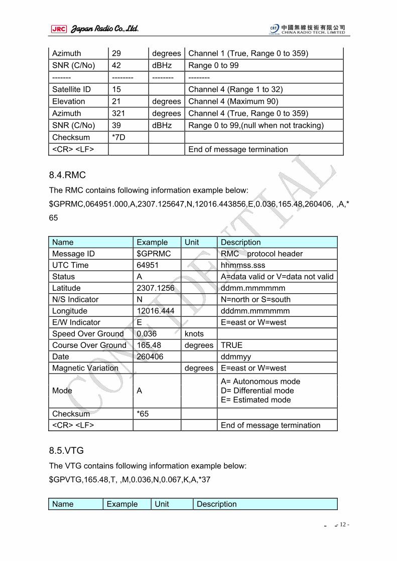
Azimuth 29 degrees Channel 1 (True, Range 0 to 359) SNR (C/No) 42 dBHz Range 0 to 99 ------- -------- -------- -------- Satellite ID 15 Channel 4 (Range 1 to 32) Elevation 21 degrees Channel 4 (Maximum 90) Azimuth 321 degrees Channel 4 (True, Range 0 to 359) SNR (C/No) 39 dBHz Range 0 to 99,(null when not tracking) Checksum *7D <CR> <LF> End of message termination
8.4.RMC The RMC contains following information example below:
$GPRMC,064951.000,A,2307.125647,N,12016.443856,E,0.036,165.48,260406, ,A,*
65
Name Example Unit Description Message ID $GPRMC RMC protocol header UTC Time 64951 hhmmss.sss Status A A=data valid or V=data not validLatitude 2307.1256 ddmm.mmmmmm N/S Indicator N N=north or S=south Longitude 12016.444 dddmm.mmmmmm E/W Indicator E E=east or W=west Speed Over Ground 0.036 knots Course Over Ground 165.48 degrees TRUE Date 260406 ddmmyy Magnetic Variation degrees E=east or W=west
Mode A A= Autonomous mode D= Differential mode E= Estimated mode
Checksum *65 <CR> <LF> End of message termination
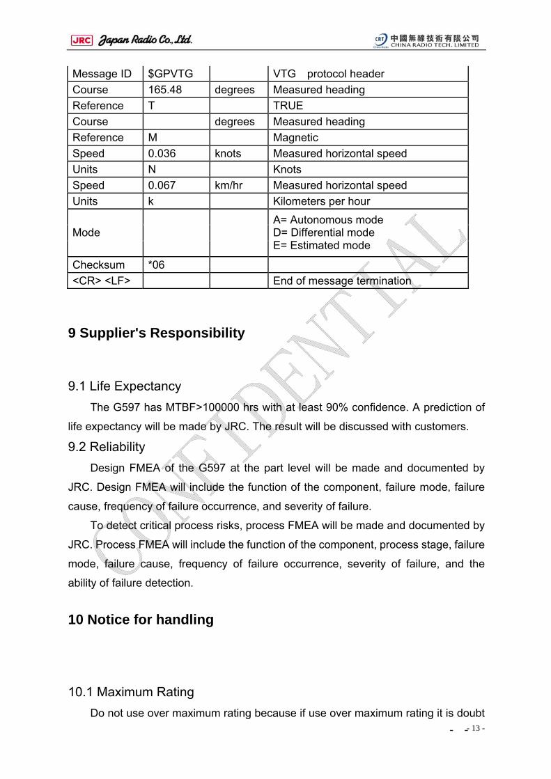
8.5.VTG The VTG contains following information example below:
$GPVTG,165.48,T, ,M,0.036,N,0.067,K,A,*37
Name Example Unit Description
- -
- 13 -
Message ID $GPVTG VTG protocol header Course 165.48 degrees Measured heading Reference T TRUE Course degrees Measured heading Reference M Magnetic Speed 0.036 knots Measured horizontal speed Units N Knots Speed 0.067 km/hr Measured horizontal speed Units k Kilometers per hour
Mode A= Autonomous mode D= Differential mode E= Estimated mode
Checksum *06 <CR> <LF> End of message termination
9 Supplier's Responsibility
9.1 Life Expectancy The G597 has MTBF>100000 hrs with at least 90% confidence. A prediction of
life expectancy will be made by JRC. The result will be discussed with customers.
9.2 Reliability Design FMEA of the G597 at the part level will be made and documented by
JRC. Design FMEA will include the function of the component, failure mode, failure
cause, frequency of failure occurrence, and severity of failure.
To detect critical process risks, process FMEA will be made and documented by
JRC. Process FMEA will include the function of the component, process stage, failure
mode, failure cause, frequency of failure occurrence, severity of failure, and the
ability of failure detection.
10 Notice for handling
10.1 Maximum Rating Do not use over maximum rating because if use over maximum rating it is doubt
- -
- 14 -
become the fault.
Maximum voltage
It is regulated maximum voltage which compensate input voltage between input
terminal and GND.
Once over the maximum voltage is inputted, it is become the reason of faulty.
Input Voltage
It is regulated maximum voltage to input terminal. Once over the maximum
voltage is inputted, it is become the reason of faulty.
Operating Temperature
It is the temperature rang which can have a guarantee for operating corestly.
Once over the temperature rang it is become the reason of faulty or it is doubt that
can not have the satisfy of the function of GPS.
Storage Temperature
It is the temperature range which unit is strong in case storage temperature is
over this temperature rang, it is become the reason of faulty or it can not have a
satisfy of the function.
10.2 Caution for Installation In case handle with this unit, be careful against a static electricity. It is not that
unit will be damaged by a static electricity. Specially, handle with I/O connector, be
careful against a static electricity. Do not touch the I/O connector dirty with hand.
Please mount within two weeks after opening the prevention-of-moisture packing.
After the prevention-of-moisture packing is opened, it need be kept in dry
atmosphere.
10.3 Notice for Storage Do not storage the place where corrosion gas will be generated or exist many
dusts. Do not storage the place where temperature rang will be change widely
because the dewdrop will be formed therefore.
10.4 Transportation Do not throw, do not drop, otherwise unit itself will be damaged.
- -
- 15 -
Protect from water, when transport in the rain/snow, protect from them.
10.5 Overcurrent Protection The G597 dose not have a fuse for overcurrent protect.
Please put a fuse for overcurrent protect in your system because the prevention
of danger.
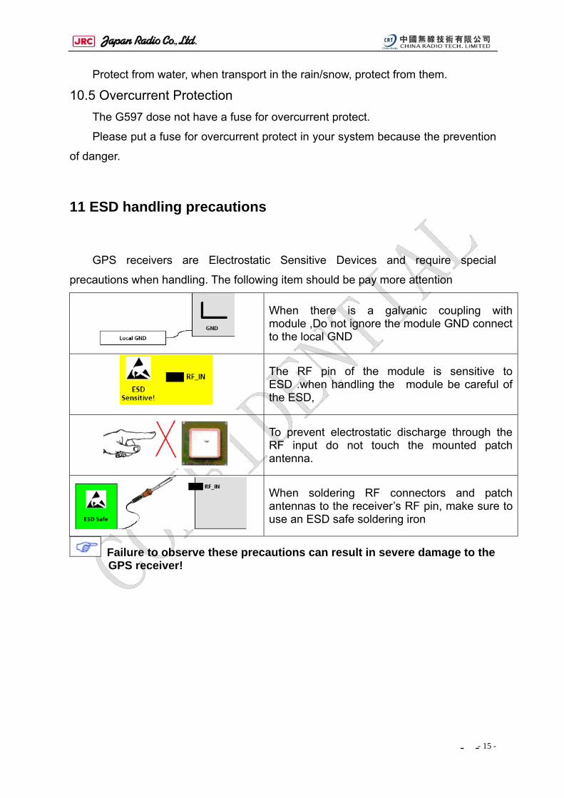
11 ESD handling precautions
GPS receivers are Electrostatic Sensitive Devices and require special
precautions when handling. The following item should be pay more attention
When there is a galvanic coupling with module ,Do not ignore the module GND connect to the local GND
The RF pin of the module is sensitive to ESD .when handling the module be careful of the ESD,
To prevent electrostatic discharge through the RF input do not touch the mounted patch antenna.
When soldering RF connectors and patch antennas to the receiver’s RF pin, make sure to use an ESD safe soldering iron
Failure to observe these precautions can result in severe damage to the GPS receiver!
- -
- 16 -
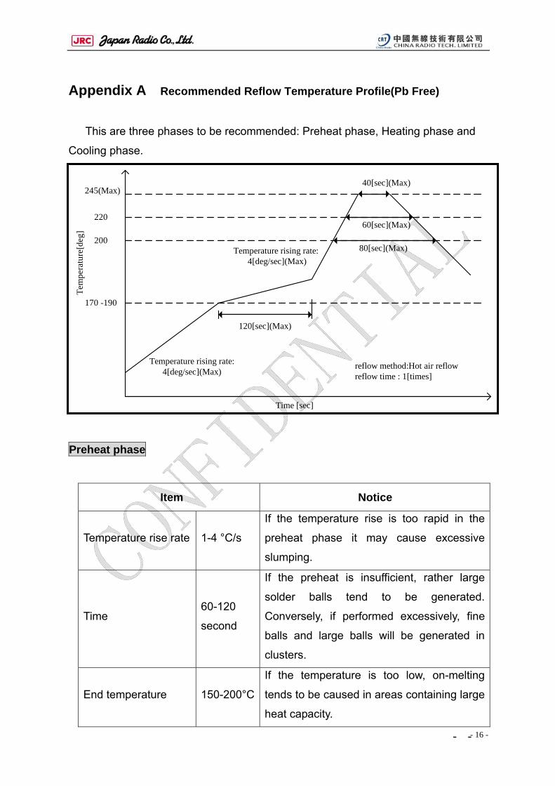
Appendix A Recommended Reflow Temperature Profile(Pb Free)
This are three phases to be recommended: Preheat phase, Heating phase and
Cooling phase.
Preheat phase
Item Notice
Temperature rise rate 1-4 °C/s
If the temperature rise is too rapid in the
preheat phase it may cause excessive
slumping.
Time 60-120
second
If the preheat is insufficient, rather large
solder balls tend to be generated.
Conversely, if performed excessively, fine
balls and large balls will be generated in
clusters.
End temperature 150-200°C
If the temperature is too low, on-melting
tends to be caused in areas containing large
heat capacity.
Temperature rising rate:4[deg/sec](Max)
120[sec](Max)
80[sec](Max)
60[sec](Max)
245(Max)
220
200
170 -190
Tem
pera
ture
[deg
]
reflow method:Hot air reflowreflow time : 1[times]
40[sec](Max)
Time [sec]
Temperature rising rate: 4[deg/sec](Max)
- -
- 17 -
Heating phase Two points need to be noticed:
Limit time above 220°C liquidus temperature: 20 - 40s
Peak reflow temperature: 230 - 245°C
Cooling phase
Temperature fall rate 6°C / s (max)
To avoid falling off during SMT, We request that the G597 module
should be place on the topside of the motherboard . (为避免二次过炉
对模块造成损坏,我们要求客户在SMT时,后贴包含模块的面。)
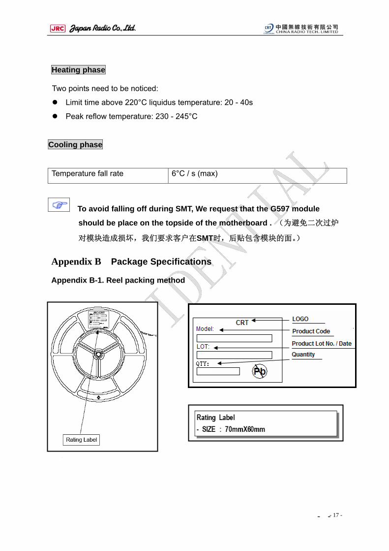
Appendix B Package Specifications
Appendix B-1. Reel packing method
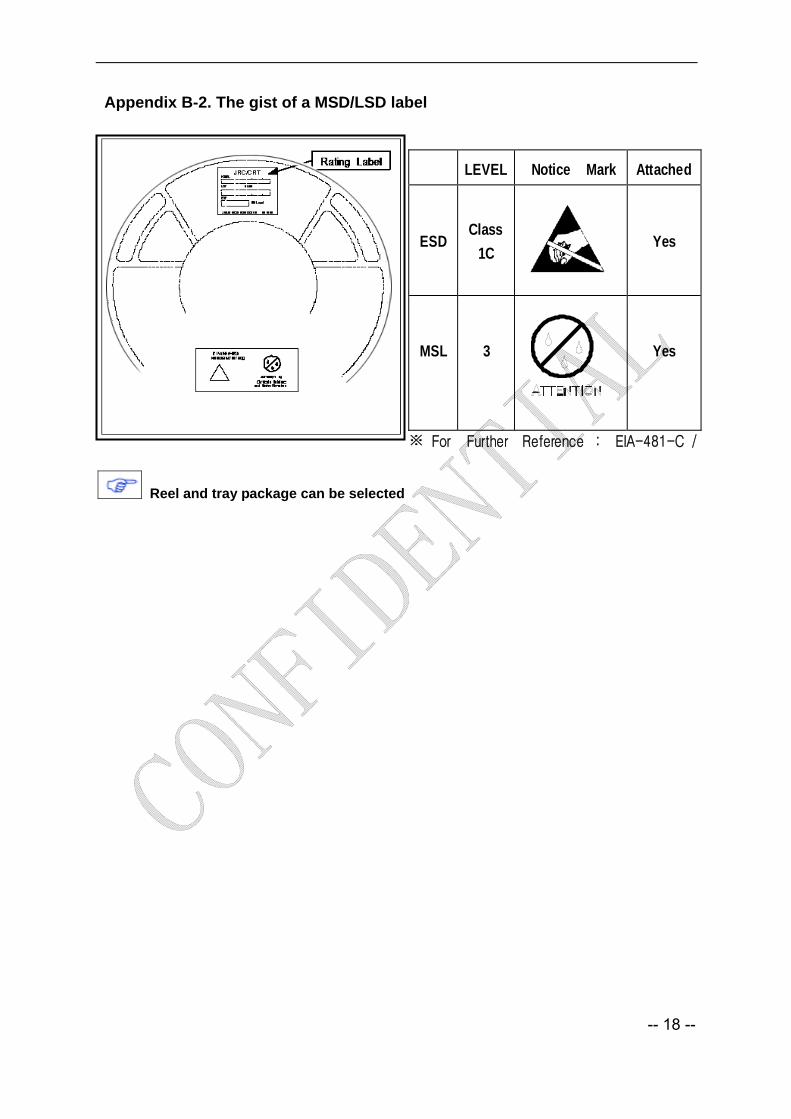
LEVEL
Notice Mark
Attached
ESD
Class1C
Yes
MSL
3
Yes
※ For Further Reference : EIA-481-C /
Appendix B-2. The gist of a MSD/LSD label
Reel and tray package can be selected
-- 18 --