Embed Size (px)
Citation preview
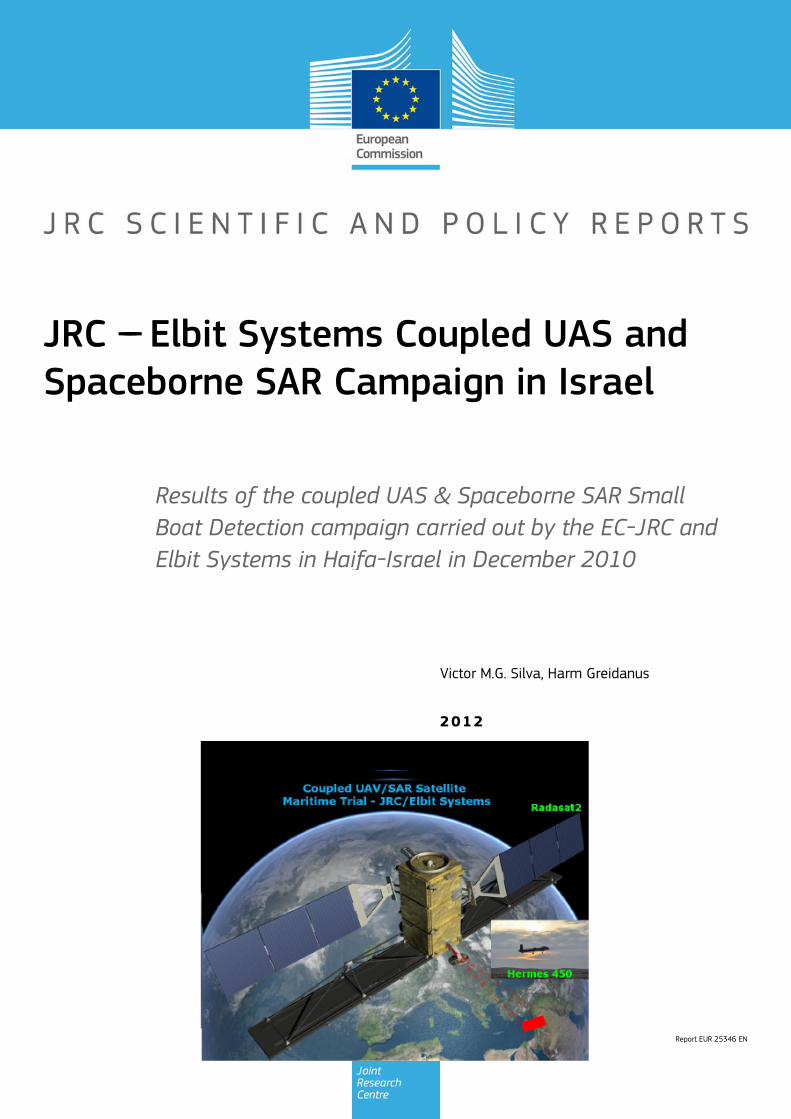
Report EUR 25346 EN
2012
Victor MG Silva Harm Greidanus
Results of the coupled UAS amp Spaceborne SAR Small Boat Detection campaign carried out by the EC-JRC and Elbit Systems in Haifa-Israel in December 2010
JRC --- Elbit Systems Coupled UAS and Spaceborne SAR Campaign in Israel
European Commission Joint Research Centre
Institute for the Protection and Security of the Citizen
Contact information Forename Surname
Address Joint Research Centre Via Enrico Fermi 2749 TP670 21027 Ispra (VA) Italy
E-mail harmgreidanusjrceceuropaeu
Tel +39 0332 78 9739
Fax +39 0332 78 9156
httpipscjrceceuropaeu
httpwwwjrceceuropaeu
Legal Notice Neither the European Commission nor any person acting on behalf of the Commission
is responsible for the use which might be made of this publication
Europe Direct is a service to help you find answers to your questions about the European Union
Freephone number () 00 800 6 7 8 9 10 11
() Certain mobile telephone operators do not allow access to 00 800 numbers or these calls may be billed
A great deal of additional information on the European Union is available on the Internet
It can be accessed through the Europa server httpeuropaeu
JRC71122
EUR 25346 EN
ISBN 978-92-79-25020-0
ISSN 1831-9424
doi10278828527
Luxembourg Publications Office of the European Union 2012
copy European Union 2012
Reproduction is authorised provided the source is acknowledged
Printed in Italy
__________________________________________________________________________________
TABLE OF CONTENTS
TABLE OF CONTENTS i TABLE OF FIGURES iii TABLE OF TABLES v EXECUTIVE SUMMARY 1
1 ndash Introduction 2 11 ndash Scope 2 12 ndash Main Objectives 2 13 ndash Context 3
2 ndash Research Method 4 21 ndash Coupled UASSpaceborne SAR Small Boat Detection 4 22 ndash UAS CONUSE and CONOPS Controlled Experiment 4
3 ndash Experiment Set Up 5 31 ndash Experiment Site Selection 5
311 ndash Open Sea Waters Site near Haifa Israel 5 32 ndash SAR Satellite Imagery Planning 6 33 ndash Partners Involved and their Roles 10
331 - European Commission (EC) ndash Joint Research Centre (JRC) 10 332 ndash Elbit Systems 10
4 ndash Experiment Execution 11 41 ndash Modus Operandi 11 42 ndash Ground Truth Data Collection 11 43 ndash Means Involved in the Experiment 11
431 ndash Boat Deployed During the Experiment 11 432 ndash Hermes 450 ndash System Overview 12 433 ndash The Air Vehicle 12 434 ndash Ground Control Station (GCS) 13 435 ndash The EO Payload 14
5 ndash Preliminary Data Analysis 16 51 ndash SAR Satellite Imagery Processing 16 52 ndash Ground Truth Data 16
521 ndash GPS coordinates of the boat deployed 16 521 ndash HERMES 450 Ground Truth Data 17
53 ndash Weather Conditions and Sea State 17 54 ndash Verification of the Results 19
541 ndash Overview of the UAV Trajectory and the SAR Imagery Footprint 19 542 ndash Targets Detected in the Radarsat-2 Spotlight Image 21
55 ndash Quantitative Analysis of the Spaceborne SAR Image 27 551 ndash Radarsat-2-Spotlight 08Dec2010 (154740 UTC) Haifa Israel 27
56 ndash Summary of the Preliminary Analysis of the Spaceborne SAR Image 30 6 ndash Preliminary Conclusions 31
61 ndash Hands-on experience with UAS technologies and its applications to maritime surveillance 34 62 ndash Potential of UAS for Maritime Surveillance 35
621 ndash Advantages of UAS for maritime Surveillance 36 622 ndash Possible Drawbacks of using UAS for maritime Surveillance 37
63 ndash Main Limiting Factors Preventing the Use of UAS 37 64 ndash UAS Key Enabling Technologies 38
JRC ndash Elbit Systems Coupled UAS Spaceborne SAR Campaign Dec 2010 Page i
__________________________________________________________________________________
JRC ndash Elbit Systems Coupled UAS Spaceborne SAR Campaign Dec 2010 Page ii
65 ndash Mission Readiness 41 651 ndash Mission Readiness Summary 41
66 ndash Small Boat Detection in SAR Satellite Imagery 42 67 ndash Limitations of current State-of-the-Art SAR Satellite technology 42
7 ndash Plans for Future Work 43 Acknowledgements 43 REFERENCES 44
__________________________________________________________________________________
TABLE OF FIGURES
Figure 1 ndash Illustration of the site of the experiment in Haifa Israel The large rectangle in red is the
footprint of the TerraSAR-X Stripmap ordered to DLR The small rectangle in red is the footprint of the Radarsat-2 Spotlight spaceborne SAR image ordered to MDA Only the Radarsat-2 image was actually acquired DLR was not able to acquire the TerraSAR-X image due to technical problems 5
Figure 2 ndash The rectangle in red illustrates de footprint of the TerraSAR-X Stripmap image ordered to DLR Fortunately due to technical problems DLR was not able to acquire this spaceborne SAR image The approximate start date of acquisition was 2010-12-08T15380373 6
Figure 3 ndash The rectangle in pink illustrates de footprint of the Radarsat-2 Spotlight SAR image ordered to MDA Fortunately due to technical problems DLR was not able to acquire this spaceborne SAR image The approximate start date of acquisition was 2010-12-08T15474000 UTC 7
Figure 4 ndash Radarsart2 image modes The Ultrafine and the Spotlight modes have been identified as the most suitable modes for this particular experiment 8
Figure 5 ndash Radarsart2 image modes The Ultrafine and the Spotlight modes have been identified as the most suitable modes for this particular experiment 9
Figure 6 ndash The 12-meter boat deployed during the experiment at the Port of Haifa Israel 12 Figure 7 ndash Elements of the Hermes UAV System 13 Figure 8 ndash The UAS Hermes 450 Ground Control Station (GCS) 14 Figure 9 ndash CoMPASS Stabilized Turret Assembly (STA) 15 Figure 10 ndash Weather data (Temperature Barometric Pressure Wind Speed and Wind Direction) for
Haifa Israel on 8 Dec 2010 18 Figure 11 ndash Google Earth UAV trajectory during the experiment and footprinst of the SAR imagery
ordered for the experiment 19 Figure 12 ndash Zoom in of the previous figure showing a more detailed view of the UAV trajectory and
of the port of Haifa in Israel 20 Figure 13 ndash Zoom in of the previous figure showing a even more detailed view of the UAV trajectory
and of the port of Haifa in Israel 20 Figure 14 ndash Google Earth positions of the elbitrsquos boat and the UAV (Hermes450) at the approximate
time of the SAR Satellite overpass by 174740 UTC 21 Figure 15 ndash On the background the SAR image with the two UAV positions before and after the
satellite overpass (Pin1 and Pin2) and the Elbitacutes Boat position (Pin3) The small window over the SAR image shows a zoom in of the SAR image where the SAR signature of the Elbitacutes Boat can clearly be seen The top right are of the SAR image also shows SAR signatures of several large ships in the area at the time of the SAR satellite overpass 22
Figure 16 ndash Zoom-in of figure 15 with the UAV images of some targets On the top left the UAV IR image of the Elbitrsquos Boat On the centre left the UAV IR image of a large ship On the centre right the UAV IR image of a large ship On the bottom right the UAV IR image of a large ship 23
Figure 17 ndash Photo taken in Haifa Israel a couple of hours before the SAR satellites overpass This phot shows the large ships moored in the area Most of these large ships were detected in the Radarsat-2 image As expected their positions and orientations were slightly different at the time of the satellite overpass 24
JRC ndash Elbit Systems Coupled UAS Spaceborne SAR Campaign Dec 2010 Page iii
__________________________________________________________________________________
JRC ndash Elbit Systems Coupled UAS Spaceborne SAR Campaign Dec 2010 Page iv
Figure 18 ndash Photo taken in Haifa Israel a couple of hours before the SAR satellites overpass This phot shows the large ships moored in the area Most of these large ships were detected in the Radarsat-2 image As expected their positions and orientations were slightly different at the time of the satellite overpass 25
Figure 19 ndash UAV IR image of a small pier in the port of Haifa Israel where 7 small boats can be seen with enough detail to allow classification This image was acquired from an altitude of about 5500 meters in the dark 26
Figure 20 ndash Radarsat-2 Spotlgiht image (08Dec2010) ndash Sigma Naught (Intensity) band 27 Figure 21 ndash Radarsat-2 Spotlgiht image (08Dec2010) - On the left the Sigma Naught (σdeg) (intensity)
and on the right the Sigma Naught (σdeg) (dB) 28 Figure 22 ndash Radarsat-2 Spotlgiht image (08Dec2010) - On the left the Beta Naught (βdeg) and on the
right the Gamma Naught (γdeg) (dB) 28 Figure 23 ndash Radarsat-2 Spotlgiht image (08Dec2010) - On the top left the Sigma Naught (σdeg) after
colour manipulation to enhance the targets and on the top right the corresponding histogram On the bottom we can see the histogram of the image 29
Figure 24 ndash The area of the experiment is indicated by the GPS Trajectory of the UAV 35 Figure 25 ndash Unmanned Aerial Vehicle System Enabled by Autonomous Mission Management
Reliable Flight Systems Navigation Accurate Systems Terrain Avoidance Power and Propulsion 38
Figure 26 ndash System Element Designs Needed to Transition from Current to Next-Generation Autonomous UAV Systems 40
Figure 27 ndash Technology Maturation Summaries in Terms of Mission-Derived Capabilities 41
__________________________________________________________________________________
TABLE OF TABLES Table 1ndash TerraSAR-X Stripmap and Radarsat2- Spotlight High Resolution 08-Dec-2010 7 Table 2 ndash Summary of Hermes 450 main characteristics 13 Table 3 ndash Ground Truth data collected at the time of the satellite pass (154740 UTC=174740 LT) on
8 December 2010 16 Table 4 ndash Hermes 450 Ground Truth Data 17 Table 5 ndash Wind speed wind direction and Temperature 17 Table 8 ndash Statistics of the Radarsat-2 Spotlgiht image (08Dec2010) (154740 UTC) 30 Table 9 ndash List of SAR Satellite Images acquired during the experiment and detected boats 30 Table 10 ndash Minimum and maximum Sigma Naught (σdeg) of the targets detected in each SAR image 30 Table 11 ndash The Main Maritime Security and Safety Threats vs Gaps and the technologies that can be
used to mitigate them 33 Table 12 ndash Key Enabling Technologies (from SG75 study on autonomous systems) 39
JRC ndash Elbit Systems Coupled UAS Spaceborne SAR Campaign Dec 2010 Page v
__________________________________________________________________________________
JRC ndash Elbit Systems Coupled UAS Spaceborne SAR Campaign Dec 2010 Page 1
EXECUTIVE SUMMARY The European maritime area is one of Europersquos most important assets with regard to resources security and ultimately prosperity of the Member States A significant part of Europersquos economy relies directly or indirectly on it It is not just the shipping or fisheries industries and their related activities It is also shipbuilding and ports marine equipment and offshore energy maritime and coastal tourism aquaculture submarine telecommunications blue biotech and the protection of the marine environment The European maritime area faces several risks and threats posed by unlawful activities such as drugs trafficking smuggling illegal immigration organised crime and terrorism Piracy in international waters also constitutes a threat to Europe since it can disrupt the maritime transport chain These risks and threats can endanger human lives marine resources and the environment as well as significantly disrupt the transport chain and global and local security It is anticipated that these risks and threats will endure in the mid and long run In order to keep Europe as a world leader in the global maritime economy an effective integratedinteroperable sustainable maritime surveillance system and situational awareness are needed A significant number of unlawful maritime activities such as illegal immigration drugs trafficking smuggling piracy and terrorism involve mainly small boats because small boats are faster and more difficult to detect using conventional means Hence it is very important to assess emerging technologies to improve maritime surveillance in particular the capability of detecting small boats Since 2008 the EC-JRC has carried out a number of SAR Small Boat detection experiments to assess the feasibility of using Spaceborne SAR for Small Boat detection This report presents the results and conclusions of the coupled UAS and spaceborne SAR small boat detection campaign on open sea waters carried out by the EC-JRC in Haifa Israel in collaboration with Elbit Systems on 8 Dec 2010 The results of this coupled UASSpaceborne SAR small boat detection experiment show the potential of UAS for maritime surveillance and that small boat detection in spaceborne SAR is possible under suitable conditions of sea state wind speed and incidence angle In fact the experiment highlights how a UAS can fill in the maritime surveillance gap between ship-borne and land-based surveillance assets and spaceborne SAR For instance spaceborne SAR allows small boat detection under suitable sea and wind conditions However it neither allows classification nor identification of small boats A UAS besides detection also allows classification and identification Hence since most unlawful activities in the maritime domain such as illegal immigration drugs trafficking smuggling terrorism and piracy involve small boats the potential of UAS for maritime surveillance is very high However Before UAS can be routinely used for maritime surveillance in non-segregated airspace a significant number of key issues related to critical UAS systems have to be addressed namely command and control issues telecommunications (eg change over from Line of Sight (LOS) to Beyond Line of Sight (BLOS) Satcom) hand over of Air Traffic Control (ATC) between military and civil collision avoidance systems cross-border issues flight plan modifications contingency procedures legal framework and regulations etc Other interesting lines of research are UAS formation flying issues patterns for optimal surveillance onboard data fusion full autonomy and endurance and altitude issues
__________________________________________________________________________________
JRC ndash Elbit Systems Coupled UAS Spaceborne SAR Campaign Dec 2010 Page 2
1 ndash Introduction
11 ndash Scope
This report presents the key findings of the coupled UAS and Spaceborne SAR Small Boat Detection Campaign led by the EC-JRC and conducted jointly with Elbit Systems in Haifa Israel in December 2010
This study addresses the potential of Unmanned Aerial Systems (UAS) for maritime surveillance
and the feasibility of using UAS as a complementary technology on an operational basis To answer this statement of work a multinational cross-disciplinary consortium with research and
operational expertise in maritime surveillance and Unmanned Aerial Systems (UAS) was assembled with organisations involved in
1- research in maritime surveillance using Spaceborne SAR imagery and in the processing and analysis of SAR imagery as well as coordination and management of maritime surveillance campaigns (European Commission-JRC)
2- experience with Unmanned Aerial Systems (UAS) campaigns (Elbit Systems)
12 ndash Main Objectives
The work was performed with the following main objectives
To acquire hands-on experience with UAS technologies in particular with its possible applications to maritime surveillance
To assess the potential of UAS for maritime surveillance including small boat detection illegal
immigration and drugs trafficking mitigation
To study the feasibility of using UAS as a complementary maritime surveillance technology on an operational basis together with currently used technologies
To identify the main limiting factors preventing the use of UAS in non segregated airspace and
enabling factors that could help to facilitate the operational use of UAS for maritime surveillance
__________________________________________________________________________________
JRC ndash Elbit Systems Coupled UAS Spaceborne SAR Campaign Dec 2010 Page 3
13 ndash Context
Problem Statement ndash The European maritime area is one of Europersquos most important assets with regard to resources security and ultimately prosperity of the Member States A significant part of Europersquos economy relies directly or indirectly on it It is not just the shipping or fisheries industries and their related activities It is also shipbuilding and ports marine equipment and offshore energy maritime and coastal tourism aquaculture submarine telecommunications blue biotech and the protection of the marine environment The European maritime area faces several risks and threats posed by unlawful activities such as drugs trafficking smuggling illegal immigration organised crime and terrorism Piracy in international waters also constitutes a threat to Europe since it can disrupt the maritime transport chain These risks and threats can endanger human lives marine resources and the environment as well as significantly disrupt the transport chain and global and local security It is anticipated that these risks and threats will endure in the mid and long run In order to keep Europe as a world leader in the global maritime economy an effective integratedinteroperable sustainable maritime surveillance system and situational awareness are needed
A significant number of unlawful maritime activities such as illegal immigration drugs trafficking smuggling piracy and terrorism involve mainly small boats because small boats are faster and more difficult to detect using conventional means Hence it is very important to find out the feasibility of using Unmanned Aerial Systems (UAS) on an operational basis as a complementary maritime surveillance technology to currently used maritime surveillance assets such as spaceborne SAR coastal radars ship-borne radars etc
_________________________________________________________________________________
2 ndash Research Method
In order to find out the potential and feasibility of using Unmanned Aerial Systems (UAS) for maritime surveillance including small boat detection a controlled experiment on open sea and along the coast was designed set up and executed The controlled experiment is briefly described next The controlled experiment consisted of a UAS (Hermes 450W from Elbit Systems) flight over the maritime area near the Port of Haifa in Israel at the approximate time of two SAR Satellite overpasses (Radarsat-2 and TerraSAR-X) The Hermes 450 took-off from Haifa in Israel and flew to the area of the experiment The experiment was comprised two phases namely
1) the Coupled UASSpaceborne SAR Small Boat detection and 2) the CONUSE and CONOPS phase
These two phases are described next
21 ndash Coupled UASSpaceborne SAR Small Boat Detection One of the main objectives of this controlled experiment was to find out the potential of using UAS for maritime surveillance in particular to find out if a UAS could fill in the gap between ship borneland based maritime surveillance and spaceborne maritime surveillance in particular the capability of detecting small targets To that end one small boat was deployed on open sea waters a couple of nautical miles southwest of the Port of Haifa The UAS capabilities were then tested The tests comprised flying over the above mentioned area and the detection tracking and classification of the small boat deployed
22 ndash UAS CONUSE and CONOPS Controlled Experiment Another objective of this controlled experiment was to find out the potential of using UAS for maritime surveillance the rationale behind it being testing the capabilities of UAS to detect classify and identify targets on land (eg small boats piers etc) To that end the UAS acquired images of targets of opportunity to test the UAS capabilities The tests comprised flying over the above mentioned area and the detection tracking and classification of targets of opportunity as well as an attempt to detect other moving and stationary targets
__________________________________________________________________________________
JRC ndash Elbit Systems Coupled UAS Spaceborne SAR Campaign Dec 2010 Page 5
3 ndash Experiment Set Up This section describes the experiment set up namely the experiment site selection the SAR Satellite Imagery planning and the partners involved and their roles
31 ndash Experiment Site Selection Bearing in mind that most unlawful maritime activities involving small boats such as illegal immigration drugs trafficking smuggling and terrorist activities can be better mitigated if the small boats are detected at an earlier stage while on open sea the selection of open sea site scenarios for the experiment was an obvious option The open sea trials were carried out a few nautical miles off the coast of Haifa This site was selected because it is under the jurisdiction of the Israeli Air Force which made the authorisation to fly easier to obtain and reduced the risk of accidents involving people since the area is closed to the public For the same reason the tests along the coast also took place in the same area
311 ndash Open Sea Waters Site near Haifa Israel The open seacoastal waters site selected in Haifa near the port of Haifa a few nautical miles off the coast is illustrated in fig1 in Green The UAS flight plan and the Italian Airforce military airbase are also illustrated in fig1
Figure 1 ndash Illustration of the site of the experiment in Haifa Israel The large rectangle in red is the footprint of the TerraSAR-X Stripmap ordered to DLR The small rectangle in red is the footprint of the Radarsat-2 Spotlight spaceborne SAR image ordered to MDA Only the Radarsat-2 image was actually acquired DLR was not able to acquire the TerraSAR-X image due to technical problems
__________________________________________________________________________________
JRC ndash Elbit Systems Coupled UAS Spaceborne SAR Campaign Dec 2010 Page 6
32 ndash SAR Satellite Imagery Planning The Synthetic Aperture Radar (SAR) satellite imagery available at the time the planning was done comprised a Radarsat2 (Spotlight) and a TerraSAR-X (Stripmap) Figure 2 illustrates the TerraSAR-X Stripmap SAR image footprint in red The image was ordered to DLR the German Aerospace Centre but unfortunately it was not possible to acquire it due to technical problems Figure 3 illustrates the footprint of the Radarsart-2 Spotlight SAR image in red
Figure 2 ndash The rectangle in red illustrates de footprint of the TerraSAR-X Stripmap image ordered to DLR Fortunately due to technical problems DLR was not able to acquire this spaceborne SAR image The approximate start date of acquisition was 2010-12-08T15380373
__________________________________________________________________________________
JRC ndash Elbit Systems Coupled UAS Spaceborne SAR Campaign Dec 2010 Page 7
Figure 3 ndash The rectangle in pink illustrates de footprint of the Radarsat-2 Spotlight SAR image ordered to MDA Fortunately due to technical problems DLR was not able to acquire this spaceborne SAR image The approximate start date of acquisition was 2010-12-08T15474000 UTC Table-1 illustrates the SAR satellite images and image modes used in the different days of the experiment
Table 1ndash TerraSAR-X Stripmap and Radarsat2- Spotlight High Resolution 08-Dec-2010 Satellite Evening Satellite Pass 1 TerraSAR-X Stripmap 2010-12-08T15380373 UTC 2 Radarsat-2 Spotlight 2010-12-08T15474000 UTC
__________________________________________________________________________________
JRC ndash Elbit Systems Coupled UAS Spaceborne SAR Campaign Dec 2010 Page 8
The Radarsat2 and TerraSAR-X image modes used in the present experiment will be briefly reviewed in the next paragraphs Radarsat2 - Spotlight Mode ndash The Spotlight Beams are intended for applications which require the best spatial resolution available from the RADARSAT-2 SAR system In this mode the radar operates with the highest sampling rate and so the ground swath coverage is limited to keep data rate within the recorder limits Unlike the other modes Spotlight images are also of fixed size in the along track direction The ser of Spotlight Beams cover any area within the incidence angle range from 20 to 49 degrees Each beam within the set images a swath width of at least 18 km Spotlight images can only be generated in a single polarization which can be either a linear co-polarization (HH or VV) or a linear cross-polarization (HV or VH)
Figure 4 ndash Radarsart2 image modes The Ultrafine and the Spotlight modes have been identified as the most suitable modes for this particular experiment Radarsat2 - Single Beam Mode ndash Single beam mode is a stripmap SAR mode In Single Beam operation the beam elevation and profile are maintained constant throughout the data collection period The following Single Beam modes are available Standard Wide Fine Multi-Look Fine Ultra-Fine Extended High (High Incidence) Extended Low (Low Incidence) Standard Quad Polarization and Fine Quad Polarization We selected Ultra-Fine because it is the best compromise between swath coverage and resolution
__________________________________________________________________________________
JRC ndash Elbit Systems Coupled UAS Spaceborne SAR Campaign Dec 2010 Page 9
Radarsat2 - Ultra-Fine ndash The Ultra-Fine Resolution Beams are intended for applications which require very high spatial resolution In this mode the radar operates with the highest sampling rate and so the ground swath coverage is limited to keep data rate within the incidence angle from 20 to 49 degrees Each beam within the set images a swath width of at least 20 km Ultra-Fine Resolution images can only be generated in a single cross-polarization which can be either a linear co-polarization (HH or VV) or a linear cross-polarization (HV or VH) The standard TerraSAR-X operational mode is the single receive antenna mode from which the following imaging modes can be retrieved High Resolution Spotlight and Spotlight StripMap and ScanSAR The single receive antenna mode uses a chirp bandwidth of up to 300 MHz
Figure 5 ndash Radarsart2 image modes The Ultrafine and the Spotlight modes have been identified as the most suitable modes for this particular experiment The SpotLight (SL) imaging modes use phased array beam steering in azimuth direction to increase the illumination time ie the size of the synthetic aperture This leads to a restriction in the image scene size Thus the scene size is technically restricted to a defined size 10 km x 10 km for the SpotLight mode and 10 km x 5 km (width x length) in the HighResolution SpotLight (HS) mode This sophisticated imaging mode makes it possible to acquire data with up to 1 m resolution in the HighResolution SpotLight mode (acquired with a bandwidth of 300 MHz) and 2 m in the standard SpotLight mode StripMap (SM) is the basic SAR imaging mode as known eg from ERS-1 and other radar satellites The ground swath is illuminated with continuous sequence of pulses while the antenna beam is fixed in elevation and azimuth This results in an image strip with a continuous image quality (in flight direction) StripMap dual polarisation data have a slightly lower spatial resolution and smaller swath than the single polarisation data In StripMap mode a spatial resolution of up to 3 m can be achieved The standard scene size is 30 km x 50 m (width x length) in order to obtain manageable image files however acquisition length is extendable up to 1650 km
__________________________________________________________________________________
JRC ndash Elbit Systems Coupled UAS Spaceborne SAR Campaign Dec 2010 Page 10
33 ndash Partners Involved and their Roles The partners involved in this experiment comprised the European Commission (EC) ndash Joint Research Centre (JRC) and Elbit Systems from Haifa Israel The role of each partner is briefly described next 331 - European Commission (EC) ndash Joint Research Centre (JRC) ndash The main role of the EC-JRC was the planning set up execution and the analysis of the data together with Elbit Systems This comprised
a) the definition of the objectives b) the research methods used c) the ground truth data collection d) the analysis of the data and the conclusions of the experiment
332 ndash Elbit Systems ndash The main role of Elbit Systems comprised
a) the deployment and operation of the boat used as target b) the deployment and operation of the UAS Hermes 450 c) the contacts with the Israeli authorities namely the Israeli Air Force and Civil Aviation
Authority d) the collection of ground truth data e) The analysis of the data and conclusions of the experiment
__________________________________________________________________________________
JRC ndash Elbit Systems Coupled UAS Spaceborne SAR Campaign Dec 2010 Page 11
4 ndash Experiment Execution
41 ndash Modus Operandi The modus operandi of the trial was as follows 1- JRC supplied Elbit Systems with the footprint (frame) of the spaceborne SAR images to be acquired (TerraSAR-X-Stripmap and Radarsat-2 Spotlight) as well as the time of the SAR satellite passes 2- The boat was deployed about 2 nautical miles Southwest of the Port of Haifa The boat was about 12-meter long The boat had a crew of 3 people plus one JRC staff 3- The boat left from the port of Haifa and travelled a couple of nautical miles to reach the test site Once the test site was reached the boat was stationary at the time of the satellite SAR overpass After the satellite overpasses the boat was steered at different speeds to test the tracking capabilities of the UAV
42 ndash Ground Truth Data Collection The ground truth data collected comprised a) the sea state b) Data from the UAS sensors b) the weather conditions and wind speed e) Photos and movies of the boats involved in the experiment
43 ndash Means Involved in the Experiment The means involved in the experiment comprised two satellite SAR images namely a TerraSAR-X-Stripmap and a Radarsat-2 Spotlight and one 12-meter long boat 431 ndash Boat Deployed During the Experiment Figures 6 illustrate the boat deployed as target during the experiment
__________________________________________________________________________________
JRC ndash Elbit Systems Coupled UAS Spaceborne SAR Campaign Dec 2010 Page 12
Figure 6 ndash The 12-meter boat deployed during the experiment at the Port of Haifa Israel 432 ndash Hermes 450 ndash System Overview The Hermesreg UAV system is a mature and operationally proven system with accumulated experience with the Israel Defense Forces operations and with other users worldwide It features a fully redundant architecture leading to a high level of safety and reliability a high level of autonomy modern high performance state-of-the-art payloads and a small logistic footprint Figure 7 shows the main elements of the Hermes UAV System 433 ndash The Air Vehicle Hermesreg 450W is a modern UAV design featuring highly efficient aerodynamics composite structure and a high level of system redundancy and autonomy Its compact size and high maximumempty weight ratio enable very high mission effectiveness delivering potent payloads high endurance and a modest logistic footprint The Hermesreg 450 is in production and has accumulated over 150000 flight hours with the Israeli Air Force and other users around the globe The Hermesreg 450W uses the higher power delivered by the AR802W engine to achieve higher gross weight with the same platform greatly increasing payload and fuel carrying capability a shorter takeoff run and expanded flight envelope
__________________________________________________________________________________
JRC ndash Elbit Systems Coupled UAS Spaceborne SAR Campaign Dec 2010 Page 13
The AR802W engine is a derivative of the AR802 rotary engine with widened rotor and housing The result is a 30 gain in power to nearly 70HP Coupled to an Electronic Fuel Injection system the engine is highly efficient and has improved maintenance figures Following is a summary of the physical characteristics of the Hermes 450W air vehicle is given in Table 2
Table 2 ndash Summary of Hermes 450 main characteristics Physical Characteristics
bull Length 61 m bull Wingspan 105 m bull Fuselage diameter 0508 mm bull Max takeoff weight 550 kg bull Max internal fuel weight (including oil) 115 kg bull Max payload weight 150 kg
Figure 7 ndash Elements of the Hermes UAV System
434 ndash Ground Control Station (GCS) The GCS is a transportable system designed to perform and support all Hermesreg UAV family ground Based activities operational activities These activities include mission planning pre-flight check takeoff and landing UAV flight control mission control payloads and systems control as well as post-mission debriefing An embedded or appended training capability is optional Remote communication of video and telemetry to a C4I center via SATCOM or WAN infrastructure is optional The GCS provides a user friendly comfortable effective and protected environment for carrying out UAV missions
__________________________________________________________________________________
JRC ndash Elbit Systems Coupled UAS Spaceborne SAR Campaign Dec 2010 Page 14
The GCS is housed in a shelter with operator consoles of advanced human engineering design that provide an ergonomic operational environment The shelter is based on the NATO ACE III shelter with a side door As Israelrsquos leading C4I provider Elbit Systems has incorporated Hermesreg GCS advanced C4I capabilities including comprehensive mission planning tactical database management and tactical coordination with supported forces and command elements The Hermesreg GCS is uniquely capable of performing two UAV missions concurrently with two UAVs each of which is controlled via a separate Ground Datalink Terminal (GDT) The Hermesreg GCS requires minimal operating personnel ie mission commander and mission operator
Figure 8 ndash The UAS Hermes 450 Ground Control Station (GCS)
435 ndash The EO Payload The CoMPASS Compact Multi Purpose Advanced Stabilized System is a day and night surveillance system that includes a 3rd generation 3-5 μm zoom FLIR camera a color zoom TV CCD camera and automatic tracking capabilities The CoMPASS enables the following
bull Day and night stabilized LOS observation with capabilities of target detection recognition and identification in various weather conditions
bull Automatic and manual tracking of targets bull Slaving CoMPASS Line of Sight (LOS) to external systems bull LOS information bull Target Laser designationampRanging or only Target Laser Ranging bull Laser Target Marker
__________________________________________________________________________________
JRC ndash Elbit Systems Coupled UAS Spaceborne SAR Campaign Dec 2010 Page 15
CoMPASS the EOIR system for UAV applications is the most advanced payload version of the CoMPASS family featuring reduced weight high degree of modularity and flexibility space-saving packaging and advanced operational and video processing features The CoMPASS based STA Stabilized Turret Assembly is a single LRU housing
bull 3rd generation 3-5 μm FLIR zoom Camera bull Color Zoom TV CCD Camera bull Laser Target Designator bull Laser Target Marker bull Electronic Boards
Figure 9 ndash CoMPASS Stabilized Turret Assembly (STA)
__________________________________________________________________________________
JRC ndash Elbit Systems Coupled UAS Spaceborne SAR Campaign Dec 2010 Page 16
5 ndash Preliminary Data Analysis
51 ndash SAR Satellite Imagery Processing The high resolution spaceborne SAR image was analysed visually because the resolution is good enough to allow visual analysis and the site is too close to the coast which makes automatic processing more difficult and prone to error due to artefacts caused by land targets The Hermes 450 images were also analysed visually
52 ndash Ground Truth Data This section briefly describes the Ground Truth data namely the GPS positions of the boat deployed as target during the experiment a photo of the boat as well as other relevant ground truth data collected
521 ndash GPS coordinates of the boat deployed Table 5 gives the GPS coordinates of the boat deployed during the experiment at the time of the Radarsat-2 satellite overpass Table 3 ndash Ground Truth data collected at the time of the satellite pass (154740 UTC=174740 LT) on 8 December 2010
Date 8 Dec2010 Time 154740 UTC=174740 LT Pass Ascending
SatelliteMode Radarsat-2 Spotlight Polarisation HH
Boats Type Size Latitude Longitude
Elbits 12-meter
Boat
32˚ 51830 N 32deg514980N 32863833deg N
34˚ 57961 E 34deg575766E 34966017deg E
__________________________________________________________________________________
JRC ndash Elbit Systems Coupled UAS Spaceborne SAR Campaign Dec 2010 Page 17
521 ndash HERMES 450 Ground Truth Data Table 4 shows the 12-meter Elbitacutes Boat as detected by the IR sensor of the Hermes 450 Table 4 ndash Hermes 450 Ground Truth Data Date 8 Dec2010 Time 154740 UTC=174740 LT
Platform Hermes 450
UAV Type Size Latitude Longitude
UAV Hermes
450
174730h 3284489947 N
174800h
3285089687 N
174730h 3498564048 E
174800h
3499338667 E
Elbits 12-meter
Boat UAV
Image
32˚ 51830 N 32deg514980N 32863833deg N
34˚ 57961 E 34deg575766E 34966017deg E
53 ndash Weather Conditions and Sea State The weather conditions in Haifa are summarized in Table 5 bellow
Table 5 ndash Wind speed wind direction and Temperature Time (IST) Temp Dew
Point Humidity Pressure Visibility Wind Dir
Wind Speed
Gust Speed Precip Events Conditions
550 PM 210 degC 130 degC 60 1017 hPa - North 111 kmh
31 ms - NA Clear
__________________________________________________________________________________
JRC ndash Elbit Systems Coupled UAS Spaceborne SAR Campaign Dec 2010 Page 18
Figure 10 gives the weather data (Temperature Barometric Pressure Wind Speed and Wind Direction) for Haifa Israel on 8 Dec 2010
Figure 10 ndash Weather data (Temperature Barometric Pressure Wind Speed and Wind Direction) for Haifa Israel on 8 Dec 2010
__________________________________________________________________________________
JRC ndash Elbit Systems Coupled UAS Spaceborne SAR Campaign Dec 2010 Page 19
54 ndash Verification of the Results This section briefly describes the verification of the targets detected in the spaceborne SAR image and in the Hermes 450 UAV using the ground truth data collected during the experiment
541 ndash Overview of the UAV Trajectory and the SAR Imagery Footprint Figure 11 gives an overview of the UAV trajectory the footprint of the SAR imagery and the area of the experiment near the port of Haifa The UAV trajectory is depicted in blue The large red rectangle is the footprint of the TerraSAR-X Stripmap The smaller red rectangle is the footprint of the Radarsat-2 Spotlight image
Figure 11 ndash Google Earth UAV trajectory during the experiment and footprinst of the SAR imagery ordered for the experiment Figure 12 is a zoom in of the previous image which allows a more detailed view of the UAV trajectory and of the port of Haifa Figure 13 is a zoom in of figure 12 It shows in more detail the UAV trajectory during the entire experiment and the port of Haifa in Israel
__________________________________________________________________________________
Figure 12 ndash Zoom in of the previous figure showing a more detailed view of the UAV trajectory and of the port of Haifa in Israel
Figure 13 ndash Zoom in of the previous figure showing a even more detailed view of the UAV trajectory and of the port of Haifa in Israel
JRC ndash Elbit Systems Coupled UAS Spaceborne SAR Campaign Dec 2010 Page 20
__________________________________________________________________________________
JRC ndash Elbit Systems Coupled UAS Spaceborne SAR Campaign Dec 2010 Page 21
542 ndash Targets Detected in the Radarsat-2 Spotlight Image Figure 14 illustrates the position of the Elbitrsquos boat used as target in the experiment at the approximate time of the SAR Satellite pass by 1547 UTC (1747 LT) The small photo of the boat shows the approximate position of the boat The two small planes show the positions of the UAV immediately before and after the SAR Satellite pass
Figure 14 ndash Google Earth positions of the elbitrsquos boat and the UAV (Hermes450) at the approximate time of the SAR Satellite overpass by 174740 UTC Figure 15 shows the corresponding SAR image (Radarsat-2 Spotlight) acquired during the experiment Pins 1 and 2 represent the positions of the UAV before and after the SAR satellite overpass Pin 3 illustrates the position of the Elbitacutes boat deployed at the time of the satellite overpass At this scale the SAR signature of the boat is not distinguishable from the sea clutter background However zooming in the SAR image the SAR signature can clearly be seen as illustrated in figure 12 The SAR image in figure 12 also shows several SAR signatures of large ships in the area at the time of the satellite overpass
__________________________________________________________________________________
JRC ndash Elbit Systems Coupled UAS Spaceborne SAR Campaign Dec 2010 Page 22
Elbit`s Boat
Figure 15 ndash On the background the SAR image with the two UAV positions before and after the satellite overpass (Pin1 and Pin2) and the Elbitacutes Boat position (Pin3) The small window over the SAR image shows a zoom in of the SAR image where the SAR signature of the Elbitacutes Boat can clearly be seen The top right are of the SAR image also shows SAR signatures of several large ships in the area at the time of the SAR satellite overpass Figure 16 shows the corresponding SAR image (Radarsat-2 Spotlight) acquired during the experiment and the UAV IR images of some of the targets Pins 1 and 2 represent the positions of the UAV before and after the SAR satellite overpass Pin 3 illustrates the position of the Elbitacutes boat deployed at the time of the satellite overpass At this scale the SAR signature of the boat is not distinguishable from the sea clutter background However zooming in the SAR image the SAR signature can clearly be seen as illustrated in figure 13 On the top left the UAV IR image of the Elbitrsquos Boat The SAR image in figure 13 also shows several SAR signatures of large ships in the area at the time of the satellite overpass On the centre left the UAV IR image of a large ship On the centre right the UAV IR image of a large ship On the bottom right the UAV IR image of a large ship All the UAV images were acquired at night in complete darkness from altitudes in the order of 5500 meters Nonetheless the quality and detail of the UAV images allows classification of the targets and in some cases the identification As it can be seen the potential of UAV for maritime surveillance is very promising During the experiment the UAV detected all the boats and ships in the area and tracked some of the boatsships to test the tracking capability The capability of detection and tracking targets is a critical capability for maritime surveillance
__________________________________________________________________________________
JRC ndash Elbit Systems Coupled UAS Spaceborne SAR Campaign Dec 2010 Page 23
Elbitacutes Boat
Elbit`s Boat
Figure 16 ndash Zoom-in of figure 15 with the UAV images of some targets On the top left the UAV IR image of the Elbitrsquos Boat On the centre left the UAV IR image of a large ship On the centre right the UAV IR image of a large ship On the bottom right the UAV IR image of a large ship Figure 17 shows a comparison of the SAR and UAV images with an optical photo taken in Haifa Israel a couple of hours before the SAR satellites overpass Most of the large ships were detected in the SAR image and some of these ships can be identified in the optical photo Some of the ships in the photo left the area before the SAR satellites overpass
__________________________________________________________________________________
JRC ndash Elbit Systems Coupled UAS Spaceborne SAR Campaign Dec 2010 Page 24
Figure 17 ndash Photo taken in Haifa Israel a couple of hours before the SAR satellites overpass This phot shows the large ships moored in the area Most of these large ships were detected in the Radarsat-2 image As expected their positions and orientations were slightly different at the time of the satellite overpass
Elbitacutes Boat
Elbit`s Boat
__________________________________________________________________________________
JRC ndash Elbit Systems Coupled UAS Spaceborne SAR Campaign Dec 2010 Page 25
Figure 18 ndash Photo taken in Haifa Israel a couple of hours before the SAR satellites overpass This phot shows the large ships moored in the area Most of these large ships were detected in the Radarsat-2 image As expected their positions and orientations were slightly different at the time of the satellite overpass Figure 18 illustrates the SAR image and the corresponding google earth image of a small pier in the port of Haifa In the SAR image due to several artefacts it is not possible to detect the 7 small boats moored to the small pier The UAR IR image of the same area clearly shows the 7 small boats with impressive detail taking into account that the image was acquired from an altitude of about 5500 meters A zoom in of the same UAV IR image is shown in figure 19 As it can be seen although the image was acquired from an altitude of about 5500 meters the 7 small boats can be clearly seen with enough detail to allow classification of the type of boat A UAV flight at lower altitude would probably giver a lot more detail and eventually allow the identification of the small boats
__________________________________________________________________________________
JRC ndash Elbit Systems Coupled UAS Spaceborne SAR Campaign Dec 2010 Page 26
Figure 19 ndash UAV IR image of a small pier in the port of Haifa Israel where 7 small boats can be seen with enough detail to allow classification This image was acquired from an altitude of about 5500 meters in the dark
__________________________________________________________________________________
55 ndash Quantitative Analysis of the Spaceborne SAR Image In order to allow a quantitative analysis of the data the spaceborne SAR image was calibrated using ESArsquos NEST software package version 4B The input was the SAR image acquired and the output was the Radiometric Calibration (Sigma Naught (σdeg)) expressed in terms of intensity and in decibel (dB) the Radar Brightness (βdeg) and the Radiometric Normalisation (gamma naught (γdeg))
551 ndash Radarsat-2-Spotlight 08Dec2010 (154740 UTC) Haifa Israel Figure 20 illustrates the Intensity band of a subset of the Radarsat-2Spotlgiht image (08Dec2010)
Figure 20 ndash Radarsat-2 Spotlgiht image (08Dec2010) ndash Sigma Naught (Intensity) band
JRC ndash Elbit Systems Coupled UAS Spaceborne SAR Campaign Dec 2010 Page 27
__________________________________________________________________________________
Figure 21 illustrates the Sigma Naught Coefficient of the Radarsat-2 Spotlgiht image (08Dec2010) expressed in terms of intensity and decibel (dB)
Figure 21 ndash Radarsat-2 Spotlgiht image (08Dec2010) - On the left the Sigma Naught (σdeg) (intensity) and on the right the Sigma Naught (σdeg) (dB)
ormalisation amma Naught (γdeg)) of the Radarsat-2 Spotlgiht image (08Dec2010) expressed in dB
-2 Spotlgiht image (08Dec2010) - On the left the Beta Naught (βdeg) and on the right the Gamma Naught (γdeg) (dB)
Figure 22 illustrates the Radar Brightness (Beta Naught (βdeg)) and the radiometric n(G
Figure 22 ndash Radarsat
JRC ndash Elbit Systems Coupled UAS Spaceborne SAR Campaign Dec 2010 Page 28
__________________________________________________________________________________ Figure 23 shows the Sigma Naught (σdeg) in dB after some colour manipulation and the histogram of the Sigma Naught (σdeg) image
Figure 23 ndash Radarsat-2 Spotlgiht image (08Dec2010) - On the top left the Sigma Naught (σdeg) after colour manipulation to enhance the targets and on the top right the corresponding histogram On the bottom we can see the histogram of the image
Table 6 gives the statistics of the Sigma Naught (σdeg) Radarsat-2 Spotlgiht image (08Dec2010) The Sigma Naught (σdeg) range from -72897 dB up to 23465 dB The Mean value is -16855 dB the Median is -16594 dB and the standard deviation is 7077 dB
JRC ndash Elbit Systems Coupled UAS Spaceborne SAR Campaign Dec 2010 Page 29
__________________________________________________________________________________
JRC ndash Elbit Systems Coupled UAS Spaceborne SAR Campaign Dec 2010 Page 30
Table 6 ndash Statistics of the Radarsat-2 Spotlgiht image (08Dec2010) (154740 UTC)
Statistics Values Unit Only ROI-Mask pixels considered Number of pixels total Number of considered pixels Ratio of considered pixels
No 322394283 322394283
1000
Minimum Maximum
-728974609375 234655818939209
intensity_db intensity_db
Mean Median Std-Dev Coefficient of Variation
-16855686580177853 -1659462338617847 707796800831575
07888765273432338
intensity_db intensity_db intensity_db intensity_db
Checking the radar backscattering coefficient of some targets (small boat and some large ships) detected in the Radarsat-2 Spotlight image we get values ranging from -0379 dB up to 23455 dB The analysis of the Sigma Naught values (σdeg) of the targets and the area around the targets shows a significant contrast
56 ndash Summary of the Preliminary Analysis of the Spaceborne SAR Image This experiment involved two spaceborne SAR images namely a TerraSAR-X Stripmap and one Radarsat-2 Spotlight The TerraSAR-X image was not delivered by DLR due to technical problems The Elbitrsquos boat deployed during the experiment was detected in the Radarsat-2 Spotlight image Several other targets including a set of large ships were also detected Table 7 summarises the characteristics of the SAR image acquired and the targets detected
Table 7 ndash List of SAR Satellite Images acquired during the experiment and detected boats ISRAEL (HAIFA)
Date Time Place Satellite Mode Ground Truth Data Detected Boats
08Dec2010 (PM) Haifa - Israel Radarsat-2 Spotlight GPSPhotosMovies 1 small boat deployed + 9 large ships
Table 8 gives the minimum and maximum Sigma Naught (σdeg) of the targets detected in each SAR image
Table 8 ndash Minimum and maximum Sigma Naught (σdeg) of the targets detected in each SAR image
Date Time UTC (LT)Pass Satellite Image Mode Polarisation Sigma Naught (σdeg) Min Max
29Oct2010528UTC(728AM LT) DES Radarsat-2 Spotlight HH --0379 dB 23455 dB The SAR signatures of the boats deployed were very weak Some possible reasons to explain such weak signatures are the sea state the wind speed the incidence angle and the type and materials Another possible reason is the processing at DLR
__________________________________________________________________________________
JRC ndash Elbit Systems Coupled UAS Spaceborne SAR Campaign Dec 2010 Page 31
6 ndash Preliminary Conclusions The analysis of the results of this coupled UASSpaceborne SAR experiment shows a promising potential for the use of UAS for maritime surveillance UAS can be integrated into the airborne building block of maritime surveillance systems to complement the existing assets increase system performance and improve the overall maritime domain awareness The main perceived maritime security and safety threats comprise piracy terrorist and military threats weapons proliferationsmuggling drugs trafficking illegal immigration unlawful use of containers attacks to critical infrastructures and illegal fishing The main maritime security and safety gaps include a lack of technologies with the capability of detecting small targets (eg small boats) a lack of wide area and persistent maritime surveillance a lack of coordination and information sharing limited interoperability a lack of containers security a lack of persistent surveillance of critical infrastructures and early warning systems Unmanned Aircraft Systems (UAS) are an emerging technology with strong potential to mitigate the above mentioned threats by filing in the main maritime security and safety gaps listed earlier For instance the wide range of potential applications of UAS to maritime surveillance includes but is not limited to
bull detection classification and identification of small boats bull persistent maritime surveillance bull use as communications relays bull persistent surveillance of critical infrastructures bull early warning systems bull COMINT and ELINT collection etc
Table 11 illustrates the mapping of maritime securitysafety threats vs gaps and summarises the main potential applications of UAS to maritime surveillance The above mentioned potential applications of UAS to the Maritime Domain will be addressed in turn in more detail next bull Detection classification and identification of small boats ndash The capability of detecting classifying and identifying small targets (eg small boats) is among the key technologies required to improve maritime domain awareness This capability is critical to mitigate piracy illegal immigration drugs trafficking weapons smuggling illegal fishing terrorism and critical infrastructure Unmanned Aircraft Systems (UAS) provide this capability more efficiently and at a lower cost than any other existing technology bull Persistent maritime surveillance ndash With the continuous improvements of UAS technologies such as platforms sensors collision avoidance systems command and control systems telecommunications etc UAS are increasing their autonomy endurance and flexibility These characteristics are very important for persistent maritime surveillance UAS can be launched from land ships aircraft and technologies to launch UAS from submarines are currently under development UAS have distinct advantages over other existing technologies for persistent maritime surveillance in terms of autonomyendurance (the Global Surveyor has an autonomy of 1 week) cost (eg as the autonomy of UAS increases the number of staff required to operate UAS decreases) risk (eg if the UAS crashes the crew is not at risk) flexibility (eg they can be launched from a ship reducing the time to reach potential threats) etc
__________________________________________________________________________________
JRC ndash Elbit Systems Coupled UAS Spaceborne SAR Campaign Dec 2010 Page 32
bull Communications relays ndash UAS are being used as communication relays mainly in military context but have the potential to play a similar role in Civil context in several situations such as to replace satellite communications or as a redundant system over any location on Earth The main advantages of using UAS as communication relays is that airborne communication relays mitigate kinetic and noise jamming threats to satellite communications uplinks by providing an alternative set of links either directly to surface-based terminals or to satellites beyond the range of threats They are less susceptible to noise jamming threats than satellites because an adversary has to detect geolocate and track the airborne asset and operate within line of sight of the receive antenna main beam bull Persistent surveillance of critical infrastructures ndash The security of critical infrastructures such as nuclear power plants refineries ports etc requires persistent surveillance UAS can play an important role in providing persistent surveillance over critical infrastructures and over a wide area around the critical infrastructure Some advantages of UAS over other existing technologies such as ground-based assets (eg video cameras alarm systems manned aircraft etc) comprise the security of the UAS (eg hardly can be damaged or switched off as any ground-based asset) the area covered by a UAS (eg it is larger than the area covered by any ground-based asset) the cost (eg UAS is cheaper than manned aircraft with similar capability) etc bull Early warning systems ndash UAS have the potential to be used as part of an integrated system of systems for early warning A UAS can provide information about a given area at a fraction of the cost of alternative means Formation flying of UAS can cover a wide maritime area It is reasonable to assume that in a foreseeable future with the advent of UAS with increased autonomy the operations cost of UAS will likely decrease making them increasingly more attractive bull COMINT and ELINT collection ndash SIGNal INTelligence (SIGNINT) can be divided into two categories namely COMINT and ELINT COMINT stands for Communication Intelligence and ELINT for Electronic Intelligence Collection of COMINT is passive Exploitation of COMINT requires a human operator which implies COMINT UAS are suitable for COMINT and ELINT collection in different scenarios The relatively reduced amount of data collected and analysed during this experiment and the lessons learned do not allow drawing final conclusions about the feasibility of using Unmanned Aerial Systems (UAS) for maritime surveillance However this experiment allowed hands-on experience with UAS technologies and significantly improved the awareness for its applications to maritime surveillance and related issues involved including its potential the feasibility as well as the limiting and enabling factors These different aspects will now be analysed in turn in the next sections Table 11 illustrates the mapping of the main maritime security threats and gaps as well as the main priorities in terms of the different technologies involved in maritime surveillance For each maritime threat the technologies required to fill in each gap is indicated and its priority is expressed in a range of numbers (1 to 3 1 = Maximum Priority 2 = Medium Priority 3 = Low Priority) and colours (Red = Maximum Priority Orange = Medium Priority Green = Low Priority) The main technologies involved in maritime surveillance are listed on the bottom of figure 4 and are reproduced here for convenience of the reader 1- Reporting Systems 2- Sensors 3- Platforms 4- Communications 5- Data Fusion amp Sharing 6- Intelligence and 7- Databases For example the mitigation of the main threat Piracy requires filling in several maritime security gaps (eg lack of persistent surveillance lack of wide-are maritime surveillance lack of small boat detection lack of Early Warning Systems and lack of Information Sharing with maximum priority (1- Red) and among the required technologies listed are UAS LTAAV GEO-HR etc Concerning the remaining two gaps (Limited Interoperability and Containers Security) they are less relevant to mitigate Piracy hence the priority for Limited Interoperability is 2-Orange and for Containers Security is 3- Green
__________________________________________________________________________________ Table 9 ndash The Main Maritime Security and Safety Threats vs Gaps and the technologies that can be used to mitigate them
Maritime Security Main Threats GapsGapsrarr
darrThreats
Lack o f Risk As sessmentCapab ility
La ck of Persiste nt
Surveilla nce
La ck of Wid e-Area su rve illanc e
La ck of Small Boat De tecti on
Lack o f Earl y Warn ing Sys tems
L ack of In forma tion
Sh arin g
L imi ted In terop era bility
Lac k of Co ntai ners
Se cur ity
bull PiracyUAS LTAVG EO-
HR + UAS LT AVGEO-
HR + SAR GEO-HR
+ UAS USV LTAV
+ UAS LTAV
+ Coord in ationamp Sharing +
Inter opera bilityOptimisation +
1 2 3 5 6 7 1 2 3 5 6 7 1 2 3 5 6 1 2 3 123456 4567 1234567 1234567
bull Terro rismUAS LTAVG EO-
HR + UAS L TAV GEO-HR +
SAR AISGEO-HR +
UAS USV LTAV+
Intelligence+
Inte lligen ce+
Inter opera bilityOptimisation +
Intelligence+
1 2 3 5 6 7 1 2 3 5 6 1 2 3 5 6 1 2 3 123456 4567 1234567 1234567
bull Wea pon s ofM ass Dest ru ctio n Smugg ling
UAS LTAVG EO-HR +
UAS LT AVGEO-HR +
SAR AIS+
UAS USV LTAV+
Intelligence+
Inte lligen ce+
Intelligence+
Intelligence+
1 2 3 5 6 7 1 2 3 5 6 1 2 3 5 6 1 2 3 123456 4567 1234567 1234567
bull Drug sTraffic king
UAS LTAVG EO-HR +
UAS LT AVGEO-HR +
SAR AIS+
UAS USV LTAV+
Intelligence+
Inte lligen ce+
Intelligence+
Intelligence+
1 2 3 5 6 7 1 2 3 5 6 1 2 3 5 6 1 2 3 123456 4567 1234567 1234567
bull Illega lImmigratio n
UAS LTAVG EO-HR +
UAS LT AVGEO-HR +
SAR AIS+
UAS USV LTAV+
Intelligence+
Inte lligen ce+
Intelligence+
Intelligence+
1 2 3 5 6 7 1 2 3 5 6 1 2 3 5 6 1 2 3 123456 4567 1234567 1234567
bull Critic alI nfrastruc tureSecu rit y
UAS LTAVG EO-HR +
UAS LT AVGEO-HR +
SAR AIS+
UAS USV LTAV+ + Inte lligen ce
+ Intelligence
+ Intelligence
+
1 2 3 5 6 7 1 2 3 6 1 2 3 5 6 1 2 3 123456 4567 1234567 1234567
bull Illega lFish ing
UAS LTAVG EO-HR +
AI S+SAR UASLTAV +
SAR AIS GEO-HR+
UAS USV LTAV+
Intelligence+
Inte lligen ce+
Intelligence+
1 2 3 5 6 7 1 2 3 5 7 1 2 3 5 6 1 2 3 123456 4567 1234567
bull Un lawf ul Use of Co nta iners
(Secur ity)
UAS LTAVG EO-HR +
GPS Tr acking+
Intelligence+
Inte lligen ce+
GPS Int rusion Det ection Se al
1 2 3 5 6 7 4 6 7 1 2 3 5 6 1 2 3 123456 4567 1234567 1234567
(-) Priority (+) Not Rel evant
SURVEILLANCETECHNOLOGIES
1- Reporti ng Systems
2 -Sensors 3 -P latforms 4 - Communications 5- Data Fusionamp Sharing
6 -I ntelli gence 7 -Databases
JRC ndash Elbit Systems Coupled UAS Spaceborne SAR Campaign Dec 2010 Page 33
__________________________________________________________________________________
JRC ndash Elbit Systems Coupled UAS Spaceborne SAR Campaign Dec 2010 Page 34
61 ndash Hands-on experience with UAS technologies and its applications to maritime surveillance This coupled UASSpaceborne SAR campaign was a unique opportunity to acquire further handsndashon experience with UAS technologies and learn about the main issues related to its applications to maritime surveillance From the planning phase up to the execution of the UAS flight and landing there are several factors that need to be carefully analysed and taken into account A summary of the main issues identified in this experiment is given next 1- Selection of the Experiment Area Authorisation to Fly ndash For the time being UAS can only be flown in restricted areas usually under control of national authorities often the military This is due to the risks that a UAS can pose to human life and property In the present case an area under the authority of the Israeli Civil Aviation Authority was selected The authorisation to fly was not easy to obtain because the selected area is under the authority of the Civil Aviation Authority Figure 24 indicates the area of the experiment in Haifa Israel 2- UAS Communications Issues ndash The Hermes 450 was flown in Line-of-Sight (LOS) since it was close to the coast For BLOS (Beyond Line-of-Sight) operation satellite communications are required 3- Synthetic Aperture Radar (SAR) ndash The specific model Hermes 450W used in the experiment had no SAR sensor installed However a SAR sensor can be installed A SAR sensor is important for maritime surveillance since it allows 247 operations regardless of the weather conditions 4- Automatic Identification System (AIS) Receiver ndash The Hermes 450 used in this experiment was not equipped with an AIS receiver For maritime surveillance operations an AIS receiver is a very important tool since it allows the automatic identification of most ships allowing the UAS to concentrate on non-identified ships
__________________________________________________________________________________
Figure 24 ndash The area of the experiment is indicated by the GPS Trajectory of the UAV
62 ndash Potential of UAS for Maritime Surveillance UAS technologies are relatively recent and involve a wide range of fields spanning from aeronautics and sensors technologies to satellite communications and other engineering disciplines Innovations in each of the fields involved are emerging by the day UAS still have a long way to go before they become mature and their use fully operational For the time being UAS are mainly used for military applications However a large number of non-military UAS applications have been identified by stakeholders and there are several studies and demonstration flights foreseen for the near future Maritime surveillance is one of the most challenging and promising fields of application of UAS The challenges are due to the very demanding conditions under which the UAS must operate over sea and the requirements for safe operation
JRC ndash Elbit Systems Coupled UAS Spaceborne SAR Campaign Dec 2010 Page 35
__________________________________________________________________________________
JRC ndash Elbit Systems Coupled UAS Spaceborne SAR Campaign Dec 2010 Page 36
The present UAS experiment has unveiled some of the potential of UAS for maritime surveillance The UAS tests performed during this experiment include
1 ndash Detection of a Small rubber Boat and a Fishing Ship 2 ndash Tracking of a Small Boat and a Fishing Ship 3 ndash Classification of a Small Boat and a Fishing Ship 4 ndash Identification of a Small Boat and a Fishing Ship 5 ndash Detection and Tracking of People on the Beach
Despite the operational requirement that prevented the UAS from flying bellow 3km the experiment has confirmed the capability of UAS for small boat detection tracking and classification as well as the capability for people detection and tracking Concerning the identification of the targets the characteristics of the images acquired during this mission suggest that flying at lower altitudes the UAS images would allow the identification of the targets The UAS images can be seen from Figure 15 to 20
621 ndash Advantages of UAS for maritime Surveillance Some of the advantages of using UAS for maritime surveillance have been described in the literature and are summarized bellow
1- One potential benefit of UAS is that they could fill in a gap in current maritime surveillance by improving coverage
2- The range of UAS is a significant asset when compared to border agents on patrol or stationary surveillance equipment
3- Eletro-Optical InfraRed (EOIR) sensors (cameras) can identify small size objects from very high altitudes (high resolution)
4- UAS can provide precise and near-real-time imagery to a ground control operator who would then disseminate that information so that informed decisions regarding the deployment of border patrol agents can be made quickly
5- Long endurance UAS used along the border can fly for more than 30 hours up to several days without having to refuel compared with manned helicopterrsquos average flight time of just over 2 hours
6- The ability of UAS to loiter for prolonged periods of time has important operational advantages over manned aircraft
7- The longer flight times of UAS means that sustained coverage over a previously exposed area may improve maritime security
8- The range of UAVs is a significant asset when compared to border agents on patrol or stationary surveillance equipment Nevertheless the extended range and endurance of UAVs may lessen the burdens on human resources at the borders
9- UAS accidents do not risk the lives of pilots as do the helicopters and aircraft currently used by Coast Guards for border patrolling
__________________________________________________________________________________
JRC ndash Elbit Systems Coupled UAS Spaceborne SAR Campaign Dec 2010 Page 37
622 ndash Possible Drawbacks of using UAS for maritime Surveillance UAS also have disadvantages some of them are briefly described next
1- There have been concerns regarding the high accident rate of UAS which can be multiple times higher than that of manned aircraft Because UAS technology is still evolving there is less redundancy built into the operating system of UAS than of manned aircraft and until redundant systems are perfected mishap rates are expected to remain high
2- If control systems fail in a manned aircraft a well-trained pilot is better positioned to find the source of the problem because of hisher physical proximity If a UAS encountered a similar system failure or if a UAS landing was attempted during difficult weather conditions the ground control pilot would be at a disadvantage because he or she is removed from the event Unlike a manned pilot the remote pilot would not be able to assess important sensory information such as wind speed
3- Inclement weather conditions can also impinge on a UAS surveillance capability especially UAS equipped with only an EO camera and Forward Looking Infrared Radar (FLIR) because cloudy conditions and high humidity climates can distort the imagery produced by EO and FLIR equipment The effects of extreme climatic or atmospheric conditions on sensors reportedly can be mitigated with the outfit of one synthetic aperture radar (SAR) system and a moving target indicator (MTI) radar However adding SAR and MTI to a UAS platform would increase the costs associated with using UAS
4- Depending on the type of UAS the costs of operating a UAS can be higher than the costs of operating a manned aircraft This is because some types of UAS require a significant amount of logistical support and specialized operator and maintenance training Operating one UAS may require a crew of up to 20 support personnel The high comparative costs of operating some sophisticated types of UAS may be offset somewhat by their comparatively lower unit costs
63 ndash Main Limiting Factors Preventing the Use of UAS Several pre-requisites must be satisfied to render the UAS a viable cost-effective and regulated alternative to existing resources Major civil and commercial market barriers include
Single European Sky Sense and Avoid technologies Command and Control Technologies Reliability Communications (Bandwidth LOS BLOS)
Lack of airspace regulation that covers all types of UAV systems (encompassing lsquosense and avoidrsquo airspace integration and airworthiness issues)
Affordability - price and customization issues (eg commercial off-the-shelf open modular architecture) Lack of efforts to establish joint customer requirements (although this is gradually changing) Liability for civil operation Capacity for payload flexibility Lack of sufficient secure non-military frequencies for civil operation Perceived reliability (eg vehicle attrition rate vs manned aircraft) Operator training issues Recognitioncustomer perception of the UAV market Technology developments for multi-mission capability
__________________________________________________________________________________
64 ndash UAS Key Enabling Technologies Figure 25 illustrates the components of a typical UAV System showing some of the capabilities needed and the enabling technologies required for performing a given mission Any UAV mission involves many capabilities and technologies Due to the depicted system complexity the main key players such as the US Department of Defense (DoD) and other agencies have started to use the term Unmanned Aerial System (UAS) in place of UAV
Figure 25 ndash Unmanned Aerial Vehicle System Enabled by Autonomous Mission Management Reliable Flight Systems Navigation Accurate Systems Terrain Avoidance Power and Propulsion Some UAS key enabling technologies are listed below
Autonomous Mission Management Collision Avoidance Intelligent System Health Monitoring
Reliable Flight Systems Sophisticated Contingency Management Intelligent Data Handling and Processing Over-the-Horizon Communication Network-Centric Communication Open Architecture Power and Propulsion Navigation Accurate System Technology Enhanced Structures
JRC ndash Elbit Systems Coupled UAS Spaceborne SAR Campaign Dec 2010 Page 38
__________________________________________________________________________________
JRC ndash Elbit Systems Coupled UAS Spaceborne SAR Campaign Dec 2010 Page 39
Table 12 gives a more detailed description of other critical technologies for emerging autonomous UAV systems both civil and military Most of the technologies mentioned in Table 12 apply both to civil and military UAV systems Table 10 ndash Key Enabling Technologies (from SG75 study on autonomous systems)
Critical Technologies Decision Making Software
bull Fuzzy-based decision making bull Knowledge-based system bull Case-based reasoning bull Self-learning techniques bull Decision tree evaluation bull ReasoningInferring bull Probabilisticstochastic reasoning
Prediction Algorithms bull Predictive pathintent algorithms bull Short reaction algorithm bull Effectiveness evaluation
Status Assessment Software bull Internal status analysis bull Self-orientation
Situation Analysis Software bull Situation analysis bull Environmental analysis bull External status analysis
Modelling Software bull Air vehicle modelling algorithms bull Sensor modelling algorithms bull Scenario generation bull Threat system modeling bull Attack simulation bull Mission success optimisation model bull Simulation
Sensor Processing Software bull Sensor fusion bull Area of interest identification bull Automatic target recognition
Adaptive and Self-learning Systems bull Failure self-compensation
Attack Planning Software bull Attack plans and tactical alternatives bull Plan change impact identification
Weapon Engagement Procedure Software bull Weapon engagement algorithms
Mission Plan Update Software bull Route planning system bull Payload plan management system bull Mission Success Optimisation model
Path Optimisation Software bull Optimal trajectory planning bull Path Optimisation System
Targeting Software bull Target tracking bull Target prioritisation
Platform Technologies bull Obstacle detection and avoidance (airborne) bull Obstacle detection and avoidance (ground) bull Improved autopilot bull Speech recognition
Figure 26 summarises system element designs needed to transition from current to next-generation autonomous UAV systems for civilian and military UAS
__________________________________________________________________________________
Figure 26 ndash System Element Designs Needed to Transition from Current to Next-Generation Autonomous UAV Systems These new paradigms are a combination of system attributes and technological capabilities For instance the data fusion secure anti-jam and coordinated multi-vehicle control require technological development as well as specific system development to bring full maturity to unmanned systems Finally very small Micro UAVs (MAVs) and relatively large sophisticated UCAV systems are examples of the range of UAVs that are applying the new platforms payloads onboard processing communications etc to create next generation automated UAVs It is with these new platforms payloads etc that both UCAVs and MAV will be able to address similar operational challenges including
Mixed operation with other assets bull Deconfliction collision avoidance C4I integration
Operation over populated areas bull Safety issues Need to reduce reliance on communications bull UCAV ndash countermeasures bull MAV ndash limited size and power bull Limited line of sight environment Need a fully integrated system bull MAV propulsionpower generation still critical bull Operator machine interface critical bull All weather operations bull Survivability
JRC ndash Elbit Systems Coupled UAS Spaceborne SAR Campaign Dec 2010 Page 40
__________________________________________________________________________________
JRC ndash Elbit Systems Coupled UAS Spaceborne SAR Campaign Dec 2010 Page 41
65 ndash Mission Readiness
651 ndash Mission Readiness Summary This section summarises civil UAV mission readiness The purpose of Mission Readiness is to assess the readiness status of the different technologies involved in UAS In the present case this civil UAV mission readiness based on technology maturation forecasts that meet or exceed the desired or required capabilities identified by the user community Figure 27 summarises the mission readiness time forecasts for the different technologies The technologies annotated with an asterisk () are shown within the figure with maturation forecasts based on development targets expressed in the US Department of Defencesrsquo UAV Roadmap document The purpose of the chart is to be able to identify when the capability to fly a particular mission can be expected as a function of time The left-most end is the least probable and the right end the most probable timeframe
Figure 27 ndash Technology Maturation Summaries in Terms of Mission-Derived Capabilities
__________________________________________________________________________________
JRC ndash Elbit Systems Coupled UAS Spaceborne SAR Campaign Dec 2010 Page 42
66 ndash Small Boat Detection in SAR Satellite Imagery The use of spaceborne SAR imagery for small boat detection requires additional small boat detection experiments under different conditions using different methods It is not possible to draw final conclusions based on a limited number of small boat detection experiments which are not representative of the multiple possible scenarios
67 ndash Limitations of current State-of-the-Art SAR Satellite technology The main limitations of current State-of-the-Art spaceborne SAR imagery for maritime surveillance in particular aimed at small boat detection are 1 - SAR satellites repeat cycles do not allow the coverage of the same area at the required time intervals Constellations of SAR satellites could be a solution 2 - The conflict between resolution and image swath High resolution is required to detect small boats However the high resolution images have small swaths Maritime surveillance with high resolution images would require a large number of images to cover wide maritime areas which is very expensive and for the time being technically not feasible Intelligence data can play an important role by indicating an approximate position of suspicious non cooperative targets therefore reducing the surveillance area which can then be imaged using high resolution images 3- Spaceborne high resolution SAR imagery acquisition times are long enough to allow significant motion of the target during the acquisition time degrading the quality of the image Further research efforts are needed to develop new sensors and platforms As far as sensors are concerned shorter integration times are needed to prevent the blurring effect caused by the motion of the targets Regarding the platforms more platforms are needed to allow lower repeat cycles and improved coverage
__________________________________________________________________________________
JRC ndash Elbit Systems Coupled UAS Spaceborne SAR Campaign Dec 2010 Page 43
7 ndash Plans for Future Work The controlled experiments carried out by the EC-JRC together with Elbit Systems in Haifa-Israel comprised the deployment of a UAS (Hermes-450) and one small 12-meter boat A Radarsat-2 Spotlight image was acquired and several images collected by the Hermes-450 The experiment unveiled the potential of UAS for maritime surveillance in particular for detection tracking classification and possible identification of small targets The UAS was able to detect track and classify small targets such as small boats For low UAS altitude flights identification may be possible in some cases The small 12-meter boat was detected in the spaceborne SAR image The small boat detection trials carried out by the JRC were very successful since most small boats deployed during the experiments were detected in different sea states wind speeds and geographical locations The several small boat detection campaigns conducted by the EC-JRC seem to suggest that the probability of detection of small boats in spaceborne SAR images strongly depends on factors such as the sea state the wind speed the type of boat (shape and materials) the weather conditions among other factors The results of the experiments conducted thus far are not enough to draw final conclusions about the feasibility of using spaceborne SAR imagery for small boat detection However the experiments have an overall positive outcome because they indicate that under suitable sea state and wind speed conditions it is possible to detect small boats using spaceborne SAR The estimation of the probability of detection of small boats in spaceborne SAR images requires a large number of experiments under different circumstances (eg sea state wind speed characteristics of the targets image type and mode etc) Future plans include additional UAS experiments to asses its potential for maritime surveillance
Acknowledgements ndash The authors would like to express their gratitude to Elbit Systems for their cooperation logistical support and assets deployed without which the present coupled UASSAR Satellite Small Boat Detection Campaign would have not been possible
__________________________________________________________________________________
JRC ndash Elbit Systems Coupled UAS Spaceborne SAR Campaign Dec 2010 Page 44
REFERENCES [1] Elbit Systems ldquoUAV Elbit Systems Proposal for Unmanned Aerial Vehicle (UAV) flight to
collect Ground Truth data during a Maritime Surveillance Campaign and demonstrate UAV capabilities for Maritime Surveillancerdquo 2010
[2] ndash Cheryl Yuhas Suborbital Science Program Manager NASA Science Mission Directorate ldquoEarth Observations and the Role of UAVs A Capabilities Assessment Version 11rdquo Civil UAV Assessment Team httpwwwnasagovcentersdrydenresearchcivuavindexhtml August 2006
[3] ndash Document NIAG (SG75) NATO Industrial Advisory Group Study Group 75 Pre-Feasibility Study on UAV Autonomous Operations 2004
[4] ndash United States Department of Defence (DoD) Directive 50001 ldquoThe Defense Acquisition Systemrdquo and DoD Instruction 50002 ldquoOperation of the Defense Acquisition Systemrdquo
[5] ndash Mr James Ramage Mr Massimo Avalle Dr Erik Berglund Dr Luigi Crovella Mr Robert Frampton Dr Uwe Krogmann Mr Christian Ravat Mr Mike Robinson Dr Axel Schulte Dr Scott Wood ldquoRTO-TR-SCI-118 - Automation Technologies and Application Considerations for Highly Integrated Mission Systemsrdquo RTO-TR-SCI-118 AC323(SCI-118)TP204 January 2009
[6] Victor MG Silva Gilles Jurquet Gabriel Marchalot Maria TG Calzado Txema Soroa Juan Sancho Adam Koubek Harm Greidanus and Claudio Savarino ldquoWide Maritime Area Airborne Surveillance (WIMA2S) WP5 Final Reportrdquo WIMAAS WP5 FP7 Project 2008-2011 - ISBN-978-92-79-22801-8 (print) 978-92-79-22802-5 (PDF) ISSN-1018-5593 (print) 1831-9424 (online) EC-JRC Scientific Report JRC 70093 2012
[7] Victor MG Silva and Harm Greidanus ldquoSpaceborne SAR Small Boat Detection Campaign in Portugal and Spainrdquo EUR 25281 EN ISBN 978-92-79-22553-6 ISSN 1831-9424 (online) EC-JRC Scientific Report JRC68160 2012
[8] Goncalves Da Silva V Van Wimersma Greidanus H Hejmanowska B Loudjani P ldquoUAS Applications With Societal Benefits ndash JRCrsquos UAS-Related Activitiesrdquo 2011-2012 UAS Yearbook - UAS Unmanned Aircraft Systems - The Global Perspective 9 (9) 2011 p 127-129 JRC66600
[9] Goncalves Da Silva V Van Wimersma Greidanus H ldquoSmall boat detection using TerraSAR-X and Radarsat2 satellite imageryrdquo 4th TerraSAR-X Science Team Meeting 14 February 2011 DLR Oberpfaffenhofen (Germany) German Aerospace Center (DLR) (Organiser) 2011 JRC63663
[10] V Silva Harm Greidanus ldquoJRC - SAR Satellite Small Boat Detection Campaign - Portoroz ndash Sloveniardquo - ISBN-13 978-92-79-21476-9 ISSN (online) 1831-9424 EC-JRC Scientific Report JRC66835 2011
[11] V Silva Harm Greidanus ldquoJRC - SAR satellite small boat detection campaign - Algarve Portugalrdquo - ISBN-13 978-92-79-21265-9 ISSN (online) 1831-9424 ISSN (print) 1018-5593 EC-JRC Scientific Report JRC66631 2011
[12] ndash Goncalves Da Silva V Van Wimersma Greidanus H ldquoJRC-Frontex Spaceborne SAR Small Boat Detection Campaign ndash Italy amp Spainrdquo - ISBN-13 978-92-79-22213-9 ISSN (online) 1831-9424 EC-JRC Scientific Report JRC67517 2011
[13] - PW Vachon SJ Thomas J Cranton HR Edel and MD Henschel Validation of ship detection by the RADARSAT synthetic aperture radar and the Ocean Monitoring Workstation Canadian Journal of Remote Sensing 26(3)200ndash212 2000
[14] - Crisp D (2004) The state-of-the-art in ship detection in Synthetic Aperture Radar imagery DSTO Information Sciences Laboratory Australia
[15] - Joint Research Centre (JRC) of the European Community mdash IMPAST and DECLIMS web site httpintelligencejrcceceuintmarinefishindexhtm
[16] - McCandless SW Jackson CR (2004) Principles of Synthetic Aperture Radar Synthetic Aperture Radar Marine Users Manual NOAA Washington pp 1-23
[17] - Greidanus H (2008) Satellite Imaging for Maritime Surveillance of the European Seas Remote Sensing of the European Seas 343-358
European Commission
EUR 25346 EN --- Joint Research Centre --- Institute for the Protection and Security of the Citizen
Title JRC --- Elbit Systems Coupled UAS and Spaceborne SAR Campaign in Israel
Authors Victor MG Silva Harm Greidanus
Luxembourg Publications Office of the European Union
2012 --- v+44 pp --- 210 x 297 cm
EUR --- Scientific and Technical Research series --- ISSN 181-9424 (online) ISSN 1018-5593 (print)
ISBN 978-92-79-25020-0
doi10278828527
Abstract The European maritime area is one of Europersquos most important assets with regard to resources security and ultimately
prosperity of the Member States A significant part of Europersquos economy relies directly or indirectly on it It is not just the
shipping or fisheries industries and their related activities It is also shipbuilding and ports marine equipment and offshore
energy maritime and coastal tourism aquaculture submarine telecommunications blue biotech and the protection of the
marine environment The European maritime area faces several risks and threats posed by unlawful activities such as drugs
trafficking smuggling illegal immigration organised crime and terrorism Piracy in international waters also constitutes a threat
to Europe since it can disrupt the maritime transport chain These risks and threats can endanger human lives marine resources
and the environment as well as significantly disrupt the transport chain and global and local security It is anticipated that these
risks and threats will endure in the mid and long run In order to keep Europe as a world leader in the global maritime economy
an effective integratedinteroperable sustainable maritime surveillance system and situational awareness are needed
A significant number of unlawful maritime activities such as illegal immigration drugs trafficking smuggling piracy and
terrorism involve mainly small boats because small boats are faster and more difficult to detect using conventional means
Hence it is very important to find out the feasibility of using Unmanned Aerial Systems (UAS) for small boat detection tracking
classification and identification as well as to study the potential of UAS for maritime surveillance Since 2010 the EC-JRC has
carried out a number of UAS maritime surveillance campaigns to study the potential of UAS for maritime surveillance in
particular for small boat detection This report presents the results and conclusions of the JRC --- Elbit Systems Coupled UAS and
Spaceborne SAR campaign carried out in Dec 2010 in Haifa Israel
As the Commissionrsquos in-house science service the Joint Research Centrersquos mission is to provide EU policies with independent evidence-based scientific and technical support throughout the whole policy cycle Working in close cooperation with policy Directorates-General the JRC addresses key societal challenges while stimulating innovation through developing new standards methods and tools and sharing and transferring its know-how to the Member States and international community Key policy areas include environment and climate change energy and transport agriculture and food security health and consumer protection information society and digital agenda safety and security including nuclear all supported through a cross-cutting and multi-disciplinary approach
LB-NA-25346-EN
-N
__________________________________________________________________________________
TABLE OF CONTENTS
TABLE OF CONTENTS i TABLE OF FIGURES iii TABLE OF TABLES v EXECUTIVE SUMMARY 1
1 ndash Introduction 2 11 ndash Scope 2 12 ndash Main Objectives 2 13 ndash Context 3
2 ndash Research Method 4 21 ndash Coupled UASSpaceborne SAR Small Boat Detection 4 22 ndash UAS CONUSE and CONOPS Controlled Experiment 4
3 ndash Experiment Set Up 5 31 ndash Experiment Site Selection 5
311 ndash Open Sea Waters Site near Haifa Israel 5 32 ndash SAR Satellite Imagery Planning 6 33 ndash Partners Involved and their Roles 10
331 - European Commission (EC) ndash Joint Research Centre (JRC) 10 332 ndash Elbit Systems 10
4 ndash Experiment Execution 11 41 ndash Modus Operandi 11 42 ndash Ground Truth Data Collection 11 43 ndash Means Involved in the Experiment 11
431 ndash Boat Deployed During the Experiment 11 432 ndash Hermes 450 ndash System Overview 12 433 ndash The Air Vehicle 12 434 ndash Ground Control Station (GCS) 13 435 ndash The EO Payload 14
5 ndash Preliminary Data Analysis 16 51 ndash SAR Satellite Imagery Processing 16 52 ndash Ground Truth Data 16
521 ndash GPS coordinates of the boat deployed 16 521 ndash HERMES 450 Ground Truth Data 17
53 ndash Weather Conditions and Sea State 17 54 ndash Verification of the Results 19
541 ndash Overview of the UAV Trajectory and the SAR Imagery Footprint 19 542 ndash Targets Detected in the Radarsat-2 Spotlight Image 21
55 ndash Quantitative Analysis of the Spaceborne SAR Image 27 551 ndash Radarsat-2-Spotlight 08Dec2010 (154740 UTC) Haifa Israel 27
56 ndash Summary of the Preliminary Analysis of the Spaceborne SAR Image 30 6 ndash Preliminary Conclusions 31
61 ndash Hands-on experience with UAS technologies and its applications to maritime surveillance 34 62 ndash Potential of UAS for Maritime Surveillance 35
621 ndash Advantages of UAS for maritime Surveillance 36 622 ndash Possible Drawbacks of using UAS for maritime Surveillance 37
63 ndash Main Limiting Factors Preventing the Use of UAS 37 64 ndash UAS Key Enabling Technologies 38
JRC ndash Elbit Systems Coupled UAS Spaceborne SAR Campaign Dec 2010 Page i
__________________________________________________________________________________
JRC ndash Elbit Systems Coupled UAS Spaceborne SAR Campaign Dec 2010 Page ii
65 ndash Mission Readiness 41 651 ndash Mission Readiness Summary 41
66 ndash Small Boat Detection in SAR Satellite Imagery 42 67 ndash Limitations of current State-of-the-Art SAR Satellite technology 42
7 ndash Plans for Future Work 43 Acknowledgements 43 REFERENCES 44
__________________________________________________________________________________
TABLE OF FIGURES
Figure 1 ndash Illustration of the site of the experiment in Haifa Israel The large rectangle in red is the
footprint of the TerraSAR-X Stripmap ordered to DLR The small rectangle in red is the footprint of the Radarsat-2 Spotlight spaceborne SAR image ordered to MDA Only the Radarsat-2 image was actually acquired DLR was not able to acquire the TerraSAR-X image due to technical problems 5
Figure 2 ndash The rectangle in red illustrates de footprint of the TerraSAR-X Stripmap image ordered to DLR Fortunately due to technical problems DLR was not able to acquire this spaceborne SAR image The approximate start date of acquisition was 2010-12-08T15380373 6
Figure 3 ndash The rectangle in pink illustrates de footprint of the Radarsat-2 Spotlight SAR image ordered to MDA Fortunately due to technical problems DLR was not able to acquire this spaceborne SAR image The approximate start date of acquisition was 2010-12-08T15474000 UTC 7
Figure 4 ndash Radarsart2 image modes The Ultrafine and the Spotlight modes have been identified as the most suitable modes for this particular experiment 8
Figure 5 ndash Radarsart2 image modes The Ultrafine and the Spotlight modes have been identified as the most suitable modes for this particular experiment 9
Figure 6 ndash The 12-meter boat deployed during the experiment at the Port of Haifa Israel 12 Figure 7 ndash Elements of the Hermes UAV System 13 Figure 8 ndash The UAS Hermes 450 Ground Control Station (GCS) 14 Figure 9 ndash CoMPASS Stabilized Turret Assembly (STA) 15 Figure 10 ndash Weather data (Temperature Barometric Pressure Wind Speed and Wind Direction) for
Haifa Israel on 8 Dec 2010 18 Figure 11 ndash Google Earth UAV trajectory during the experiment and footprinst of the SAR imagery
ordered for the experiment 19 Figure 12 ndash Zoom in of the previous figure showing a more detailed view of the UAV trajectory and
of the port of Haifa in Israel 20 Figure 13 ndash Zoom in of the previous figure showing a even more detailed view of the UAV trajectory
and of the port of Haifa in Israel 20 Figure 14 ndash Google Earth positions of the elbitrsquos boat and the UAV (Hermes450) at the approximate
time of the SAR Satellite overpass by 174740 UTC 21 Figure 15 ndash On the background the SAR image with the two UAV positions before and after the
satellite overpass (Pin1 and Pin2) and the Elbitacutes Boat position (Pin3) The small window over the SAR image shows a zoom in of the SAR image where the SAR signature of the Elbitacutes Boat can clearly be seen The top right are of the SAR image also shows SAR signatures of several large ships in the area at the time of the SAR satellite overpass 22
Figure 16 ndash Zoom-in of figure 15 with the UAV images of some targets On the top left the UAV IR image of the Elbitrsquos Boat On the centre left the UAV IR image of a large ship On the centre right the UAV IR image of a large ship On the bottom right the UAV IR image of a large ship 23
Figure 17 ndash Photo taken in Haifa Israel a couple of hours before the SAR satellites overpass This phot shows the large ships moored in the area Most of these large ships were detected in the Radarsat-2 image As expected their positions and orientations were slightly different at the time of the satellite overpass 24
JRC ndash Elbit Systems Coupled UAS Spaceborne SAR Campaign Dec 2010 Page iii
__________________________________________________________________________________
JRC ndash Elbit Systems Coupled UAS Spaceborne SAR Campaign Dec 2010 Page iv
Figure 18 ndash Photo taken in Haifa Israel a couple of hours before the SAR satellites overpass This phot shows the large ships moored in the area Most of these large ships were detected in the Radarsat-2 image As expected their positions and orientations were slightly different at the time of the satellite overpass 25
Figure 19 ndash UAV IR image of a small pier in the port of Haifa Israel where 7 small boats can be seen with enough detail to allow classification This image was acquired from an altitude of about 5500 meters in the dark 26
Figure 20 ndash Radarsat-2 Spotlgiht image (08Dec2010) ndash Sigma Naught (Intensity) band 27 Figure 21 ndash Radarsat-2 Spotlgiht image (08Dec2010) - On the left the Sigma Naught (σdeg) (intensity)
and on the right the Sigma Naught (σdeg) (dB) 28 Figure 22 ndash Radarsat-2 Spotlgiht image (08Dec2010) - On the left the Beta Naught (βdeg) and on the
right the Gamma Naught (γdeg) (dB) 28 Figure 23 ndash Radarsat-2 Spotlgiht image (08Dec2010) - On the top left the Sigma Naught (σdeg) after
colour manipulation to enhance the targets and on the top right the corresponding histogram On the bottom we can see the histogram of the image 29
Figure 24 ndash The area of the experiment is indicated by the GPS Trajectory of the UAV 35 Figure 25 ndash Unmanned Aerial Vehicle System Enabled by Autonomous Mission Management
Reliable Flight Systems Navigation Accurate Systems Terrain Avoidance Power and Propulsion 38
Figure 26 ndash System Element Designs Needed to Transition from Current to Next-Generation Autonomous UAV Systems 40
Figure 27 ndash Technology Maturation Summaries in Terms of Mission-Derived Capabilities 41
__________________________________________________________________________________
TABLE OF TABLES Table 1ndash TerraSAR-X Stripmap and Radarsat2- Spotlight High Resolution 08-Dec-2010 7 Table 2 ndash Summary of Hermes 450 main characteristics 13 Table 3 ndash Ground Truth data collected at the time of the satellite pass (154740 UTC=174740 LT) on
8 December 2010 16 Table 4 ndash Hermes 450 Ground Truth Data 17 Table 5 ndash Wind speed wind direction and Temperature 17 Table 8 ndash Statistics of the Radarsat-2 Spotlgiht image (08Dec2010) (154740 UTC) 30 Table 9 ndash List of SAR Satellite Images acquired during the experiment and detected boats 30 Table 10 ndash Minimum and maximum Sigma Naught (σdeg) of the targets detected in each SAR image 30 Table 11 ndash The Main Maritime Security and Safety Threats vs Gaps and the technologies that can be
used to mitigate them 33 Table 12 ndash Key Enabling Technologies (from SG75 study on autonomous systems) 39
JRC ndash Elbit Systems Coupled UAS Spaceborne SAR Campaign Dec 2010 Page v
__________________________________________________________________________________
JRC ndash Elbit Systems Coupled UAS Spaceborne SAR Campaign Dec 2010 Page 1
EXECUTIVE SUMMARY The European maritime area is one of Europersquos most important assets with regard to resources security and ultimately prosperity of the Member States A significant part of Europersquos economy relies directly or indirectly on it It is not just the shipping or fisheries industries and their related activities It is also shipbuilding and ports marine equipment and offshore energy maritime and coastal tourism aquaculture submarine telecommunications blue biotech and the protection of the marine environment The European maritime area faces several risks and threats posed by unlawful activities such as drugs trafficking smuggling illegal immigration organised crime and terrorism Piracy in international waters also constitutes a threat to Europe since it can disrupt the maritime transport chain These risks and threats can endanger human lives marine resources and the environment as well as significantly disrupt the transport chain and global and local security It is anticipated that these risks and threats will endure in the mid and long run In order to keep Europe as a world leader in the global maritime economy an effective integratedinteroperable sustainable maritime surveillance system and situational awareness are needed A significant number of unlawful maritime activities such as illegal immigration drugs trafficking smuggling piracy and terrorism involve mainly small boats because small boats are faster and more difficult to detect using conventional means Hence it is very important to assess emerging technologies to improve maritime surveillance in particular the capability of detecting small boats Since 2008 the EC-JRC has carried out a number of SAR Small Boat detection experiments to assess the feasibility of using Spaceborne SAR for Small Boat detection This report presents the results and conclusions of the coupled UAS and spaceborne SAR small boat detection campaign on open sea waters carried out by the EC-JRC in Haifa Israel in collaboration with Elbit Systems on 8 Dec 2010 The results of this coupled UASSpaceborne SAR small boat detection experiment show the potential of UAS for maritime surveillance and that small boat detection in spaceborne SAR is possible under suitable conditions of sea state wind speed and incidence angle In fact the experiment highlights how a UAS can fill in the maritime surveillance gap between ship-borne and land-based surveillance assets and spaceborne SAR For instance spaceborne SAR allows small boat detection under suitable sea and wind conditions However it neither allows classification nor identification of small boats A UAS besides detection also allows classification and identification Hence since most unlawful activities in the maritime domain such as illegal immigration drugs trafficking smuggling terrorism and piracy involve small boats the potential of UAS for maritime surveillance is very high However Before UAS can be routinely used for maritime surveillance in non-segregated airspace a significant number of key issues related to critical UAS systems have to be addressed namely command and control issues telecommunications (eg change over from Line of Sight (LOS) to Beyond Line of Sight (BLOS) Satcom) hand over of Air Traffic Control (ATC) between military and civil collision avoidance systems cross-border issues flight plan modifications contingency procedures legal framework and regulations etc Other interesting lines of research are UAS formation flying issues patterns for optimal surveillance onboard data fusion full autonomy and endurance and altitude issues
__________________________________________________________________________________
JRC ndash Elbit Systems Coupled UAS Spaceborne SAR Campaign Dec 2010 Page 2
1 ndash Introduction
11 ndash Scope
This report presents the key findings of the coupled UAS and Spaceborne SAR Small Boat Detection Campaign led by the EC-JRC and conducted jointly with Elbit Systems in Haifa Israel in December 2010
This study addresses the potential of Unmanned Aerial Systems (UAS) for maritime surveillance
and the feasibility of using UAS as a complementary technology on an operational basis To answer this statement of work a multinational cross-disciplinary consortium with research and
operational expertise in maritime surveillance and Unmanned Aerial Systems (UAS) was assembled with organisations involved in
1- research in maritime surveillance using Spaceborne SAR imagery and in the processing and analysis of SAR imagery as well as coordination and management of maritime surveillance campaigns (European Commission-JRC)
2- experience with Unmanned Aerial Systems (UAS) campaigns (Elbit Systems)
12 ndash Main Objectives
The work was performed with the following main objectives
To acquire hands-on experience with UAS technologies in particular with its possible applications to maritime surveillance
To assess the potential of UAS for maritime surveillance including small boat detection illegal
immigration and drugs trafficking mitigation
To study the feasibility of using UAS as a complementary maritime surveillance technology on an operational basis together with currently used technologies
To identify the main limiting factors preventing the use of UAS in non segregated airspace and
enabling factors that could help to facilitate the operational use of UAS for maritime surveillance
__________________________________________________________________________________
JRC ndash Elbit Systems Coupled UAS Spaceborne SAR Campaign Dec 2010 Page 3
13 ndash Context
Problem Statement ndash The European maritime area is one of Europersquos most important assets with regard to resources security and ultimately prosperity of the Member States A significant part of Europersquos economy relies directly or indirectly on it It is not just the shipping or fisheries industries and their related activities It is also shipbuilding and ports marine equipment and offshore energy maritime and coastal tourism aquaculture submarine telecommunications blue biotech and the protection of the marine environment The European maritime area faces several risks and threats posed by unlawful activities such as drugs trafficking smuggling illegal immigration organised crime and terrorism Piracy in international waters also constitutes a threat to Europe since it can disrupt the maritime transport chain These risks and threats can endanger human lives marine resources and the environment as well as significantly disrupt the transport chain and global and local security It is anticipated that these risks and threats will endure in the mid and long run In order to keep Europe as a world leader in the global maritime economy an effective integratedinteroperable sustainable maritime surveillance system and situational awareness are needed
A significant number of unlawful maritime activities such as illegal immigration drugs trafficking smuggling piracy and terrorism involve mainly small boats because small boats are faster and more difficult to detect using conventional means Hence it is very important to find out the feasibility of using Unmanned Aerial Systems (UAS) on an operational basis as a complementary maritime surveillance technology to currently used maritime surveillance assets such as spaceborne SAR coastal radars ship-borne radars etc
_________________________________________________________________________________
2 ndash Research Method
In order to find out the potential and feasibility of using Unmanned Aerial Systems (UAS) for maritime surveillance including small boat detection a controlled experiment on open sea and along the coast was designed set up and executed The controlled experiment is briefly described next The controlled experiment consisted of a UAS (Hermes 450W from Elbit Systems) flight over the maritime area near the Port of Haifa in Israel at the approximate time of two SAR Satellite overpasses (Radarsat-2 and TerraSAR-X) The Hermes 450 took-off from Haifa in Israel and flew to the area of the experiment The experiment was comprised two phases namely
1) the Coupled UASSpaceborne SAR Small Boat detection and 2) the CONUSE and CONOPS phase
These two phases are described next
21 ndash Coupled UASSpaceborne SAR Small Boat Detection One of the main objectives of this controlled experiment was to find out the potential of using UAS for maritime surveillance in particular to find out if a UAS could fill in the gap between ship borneland based maritime surveillance and spaceborne maritime surveillance in particular the capability of detecting small targets To that end one small boat was deployed on open sea waters a couple of nautical miles southwest of the Port of Haifa The UAS capabilities were then tested The tests comprised flying over the above mentioned area and the detection tracking and classification of the small boat deployed
22 ndash UAS CONUSE and CONOPS Controlled Experiment Another objective of this controlled experiment was to find out the potential of using UAS for maritime surveillance the rationale behind it being testing the capabilities of UAS to detect classify and identify targets on land (eg small boats piers etc) To that end the UAS acquired images of targets of opportunity to test the UAS capabilities The tests comprised flying over the above mentioned area and the detection tracking and classification of targets of opportunity as well as an attempt to detect other moving and stationary targets
__________________________________________________________________________________
JRC ndash Elbit Systems Coupled UAS Spaceborne SAR Campaign Dec 2010 Page 5
3 ndash Experiment Set Up This section describes the experiment set up namely the experiment site selection the SAR Satellite Imagery planning and the partners involved and their roles
31 ndash Experiment Site Selection Bearing in mind that most unlawful maritime activities involving small boats such as illegal immigration drugs trafficking smuggling and terrorist activities can be better mitigated if the small boats are detected at an earlier stage while on open sea the selection of open sea site scenarios for the experiment was an obvious option The open sea trials were carried out a few nautical miles off the coast of Haifa This site was selected because it is under the jurisdiction of the Israeli Air Force which made the authorisation to fly easier to obtain and reduced the risk of accidents involving people since the area is closed to the public For the same reason the tests along the coast also took place in the same area
311 ndash Open Sea Waters Site near Haifa Israel The open seacoastal waters site selected in Haifa near the port of Haifa a few nautical miles off the coast is illustrated in fig1 in Green The UAS flight plan and the Italian Airforce military airbase are also illustrated in fig1
Figure 1 ndash Illustration of the site of the experiment in Haifa Israel The large rectangle in red is the footprint of the TerraSAR-X Stripmap ordered to DLR The small rectangle in red is the footprint of the Radarsat-2 Spotlight spaceborne SAR image ordered to MDA Only the Radarsat-2 image was actually acquired DLR was not able to acquire the TerraSAR-X image due to technical problems
__________________________________________________________________________________
JRC ndash Elbit Systems Coupled UAS Spaceborne SAR Campaign Dec 2010 Page 6
32 ndash SAR Satellite Imagery Planning The Synthetic Aperture Radar (SAR) satellite imagery available at the time the planning was done comprised a Radarsat2 (Spotlight) and a TerraSAR-X (Stripmap) Figure 2 illustrates the TerraSAR-X Stripmap SAR image footprint in red The image was ordered to DLR the German Aerospace Centre but unfortunately it was not possible to acquire it due to technical problems Figure 3 illustrates the footprint of the Radarsart-2 Spotlight SAR image in red
Figure 2 ndash The rectangle in red illustrates de footprint of the TerraSAR-X Stripmap image ordered to DLR Fortunately due to technical problems DLR was not able to acquire this spaceborne SAR image The approximate start date of acquisition was 2010-12-08T15380373
__________________________________________________________________________________
JRC ndash Elbit Systems Coupled UAS Spaceborne SAR Campaign Dec 2010 Page 7
Figure 3 ndash The rectangle in pink illustrates de footprint of the Radarsat-2 Spotlight SAR image ordered to MDA Fortunately due to technical problems DLR was not able to acquire this spaceborne SAR image The approximate start date of acquisition was 2010-12-08T15474000 UTC Table-1 illustrates the SAR satellite images and image modes used in the different days of the experiment
Table 1ndash TerraSAR-X Stripmap and Radarsat2- Spotlight High Resolution 08-Dec-2010 Satellite Evening Satellite Pass 1 TerraSAR-X Stripmap 2010-12-08T15380373 UTC 2 Radarsat-2 Spotlight 2010-12-08T15474000 UTC
__________________________________________________________________________________
JRC ndash Elbit Systems Coupled UAS Spaceborne SAR Campaign Dec 2010 Page 8
The Radarsat2 and TerraSAR-X image modes used in the present experiment will be briefly reviewed in the next paragraphs Radarsat2 - Spotlight Mode ndash The Spotlight Beams are intended for applications which require the best spatial resolution available from the RADARSAT-2 SAR system In this mode the radar operates with the highest sampling rate and so the ground swath coverage is limited to keep data rate within the recorder limits Unlike the other modes Spotlight images are also of fixed size in the along track direction The ser of Spotlight Beams cover any area within the incidence angle range from 20 to 49 degrees Each beam within the set images a swath width of at least 18 km Spotlight images can only be generated in a single polarization which can be either a linear co-polarization (HH or VV) or a linear cross-polarization (HV or VH)
Figure 4 ndash Radarsart2 image modes The Ultrafine and the Spotlight modes have been identified as the most suitable modes for this particular experiment Radarsat2 - Single Beam Mode ndash Single beam mode is a stripmap SAR mode In Single Beam operation the beam elevation and profile are maintained constant throughout the data collection period The following Single Beam modes are available Standard Wide Fine Multi-Look Fine Ultra-Fine Extended High (High Incidence) Extended Low (Low Incidence) Standard Quad Polarization and Fine Quad Polarization We selected Ultra-Fine because it is the best compromise between swath coverage and resolution
__________________________________________________________________________________
JRC ndash Elbit Systems Coupled UAS Spaceborne SAR Campaign Dec 2010 Page 9
Radarsat2 - Ultra-Fine ndash The Ultra-Fine Resolution Beams are intended for applications which require very high spatial resolution In this mode the radar operates with the highest sampling rate and so the ground swath coverage is limited to keep data rate within the incidence angle from 20 to 49 degrees Each beam within the set images a swath width of at least 20 km Ultra-Fine Resolution images can only be generated in a single cross-polarization which can be either a linear co-polarization (HH or VV) or a linear cross-polarization (HV or VH) The standard TerraSAR-X operational mode is the single receive antenna mode from which the following imaging modes can be retrieved High Resolution Spotlight and Spotlight StripMap and ScanSAR The single receive antenna mode uses a chirp bandwidth of up to 300 MHz
Figure 5 ndash Radarsart2 image modes The Ultrafine and the Spotlight modes have been identified as the most suitable modes for this particular experiment The SpotLight (SL) imaging modes use phased array beam steering in azimuth direction to increase the illumination time ie the size of the synthetic aperture This leads to a restriction in the image scene size Thus the scene size is technically restricted to a defined size 10 km x 10 km for the SpotLight mode and 10 km x 5 km (width x length) in the HighResolution SpotLight (HS) mode This sophisticated imaging mode makes it possible to acquire data with up to 1 m resolution in the HighResolution SpotLight mode (acquired with a bandwidth of 300 MHz) and 2 m in the standard SpotLight mode StripMap (SM) is the basic SAR imaging mode as known eg from ERS-1 and other radar satellites The ground swath is illuminated with continuous sequence of pulses while the antenna beam is fixed in elevation and azimuth This results in an image strip with a continuous image quality (in flight direction) StripMap dual polarisation data have a slightly lower spatial resolution and smaller swath than the single polarisation data In StripMap mode a spatial resolution of up to 3 m can be achieved The standard scene size is 30 km x 50 m (width x length) in order to obtain manageable image files however acquisition length is extendable up to 1650 km
__________________________________________________________________________________
JRC ndash Elbit Systems Coupled UAS Spaceborne SAR Campaign Dec 2010 Page 10
33 ndash Partners Involved and their Roles The partners involved in this experiment comprised the European Commission (EC) ndash Joint Research Centre (JRC) and Elbit Systems from Haifa Israel The role of each partner is briefly described next 331 - European Commission (EC) ndash Joint Research Centre (JRC) ndash The main role of the EC-JRC was the planning set up execution and the analysis of the data together with Elbit Systems This comprised
a) the definition of the objectives b) the research methods used c) the ground truth data collection d) the analysis of the data and the conclusions of the experiment
332 ndash Elbit Systems ndash The main role of Elbit Systems comprised
a) the deployment and operation of the boat used as target b) the deployment and operation of the UAS Hermes 450 c) the contacts with the Israeli authorities namely the Israeli Air Force and Civil Aviation
Authority d) the collection of ground truth data e) The analysis of the data and conclusions of the experiment
__________________________________________________________________________________
JRC ndash Elbit Systems Coupled UAS Spaceborne SAR Campaign Dec 2010 Page 11
4 ndash Experiment Execution
41 ndash Modus Operandi The modus operandi of the trial was as follows 1- JRC supplied Elbit Systems with the footprint (frame) of the spaceborne SAR images to be acquired (TerraSAR-X-Stripmap and Radarsat-2 Spotlight) as well as the time of the SAR satellite passes 2- The boat was deployed about 2 nautical miles Southwest of the Port of Haifa The boat was about 12-meter long The boat had a crew of 3 people plus one JRC staff 3- The boat left from the port of Haifa and travelled a couple of nautical miles to reach the test site Once the test site was reached the boat was stationary at the time of the satellite SAR overpass After the satellite overpasses the boat was steered at different speeds to test the tracking capabilities of the UAV
42 ndash Ground Truth Data Collection The ground truth data collected comprised a) the sea state b) Data from the UAS sensors b) the weather conditions and wind speed e) Photos and movies of the boats involved in the experiment
43 ndash Means Involved in the Experiment The means involved in the experiment comprised two satellite SAR images namely a TerraSAR-X-Stripmap and a Radarsat-2 Spotlight and one 12-meter long boat 431 ndash Boat Deployed During the Experiment Figures 6 illustrate the boat deployed as target during the experiment
__________________________________________________________________________________
JRC ndash Elbit Systems Coupled UAS Spaceborne SAR Campaign Dec 2010 Page 12
Figure 6 ndash The 12-meter boat deployed during the experiment at the Port of Haifa Israel 432 ndash Hermes 450 ndash System Overview The Hermesreg UAV system is a mature and operationally proven system with accumulated experience with the Israel Defense Forces operations and with other users worldwide It features a fully redundant architecture leading to a high level of safety and reliability a high level of autonomy modern high performance state-of-the-art payloads and a small logistic footprint Figure 7 shows the main elements of the Hermes UAV System 433 ndash The Air Vehicle Hermesreg 450W is a modern UAV design featuring highly efficient aerodynamics composite structure and a high level of system redundancy and autonomy Its compact size and high maximumempty weight ratio enable very high mission effectiveness delivering potent payloads high endurance and a modest logistic footprint The Hermesreg 450 is in production and has accumulated over 150000 flight hours with the Israeli Air Force and other users around the globe The Hermesreg 450W uses the higher power delivered by the AR802W engine to achieve higher gross weight with the same platform greatly increasing payload and fuel carrying capability a shorter takeoff run and expanded flight envelope
__________________________________________________________________________________
JRC ndash Elbit Systems Coupled UAS Spaceborne SAR Campaign Dec 2010 Page 13
The AR802W engine is a derivative of the AR802 rotary engine with widened rotor and housing The result is a 30 gain in power to nearly 70HP Coupled to an Electronic Fuel Injection system the engine is highly efficient and has improved maintenance figures Following is a summary of the physical characteristics of the Hermes 450W air vehicle is given in Table 2
Table 2 ndash Summary of Hermes 450 main characteristics Physical Characteristics
bull Length 61 m bull Wingspan 105 m bull Fuselage diameter 0508 mm bull Max takeoff weight 550 kg bull Max internal fuel weight (including oil) 115 kg bull Max payload weight 150 kg
Figure 7 ndash Elements of the Hermes UAV System
434 ndash Ground Control Station (GCS) The GCS is a transportable system designed to perform and support all Hermesreg UAV family ground Based activities operational activities These activities include mission planning pre-flight check takeoff and landing UAV flight control mission control payloads and systems control as well as post-mission debriefing An embedded or appended training capability is optional Remote communication of video and telemetry to a C4I center via SATCOM or WAN infrastructure is optional The GCS provides a user friendly comfortable effective and protected environment for carrying out UAV missions
__________________________________________________________________________________
JRC ndash Elbit Systems Coupled UAS Spaceborne SAR Campaign Dec 2010 Page 14
The GCS is housed in a shelter with operator consoles of advanced human engineering design that provide an ergonomic operational environment The shelter is based on the NATO ACE III shelter with a side door As Israelrsquos leading C4I provider Elbit Systems has incorporated Hermesreg GCS advanced C4I capabilities including comprehensive mission planning tactical database management and tactical coordination with supported forces and command elements The Hermesreg GCS is uniquely capable of performing two UAV missions concurrently with two UAVs each of which is controlled via a separate Ground Datalink Terminal (GDT) The Hermesreg GCS requires minimal operating personnel ie mission commander and mission operator
Figure 8 ndash The UAS Hermes 450 Ground Control Station (GCS)
435 ndash The EO Payload The CoMPASS Compact Multi Purpose Advanced Stabilized System is a day and night surveillance system that includes a 3rd generation 3-5 μm zoom FLIR camera a color zoom TV CCD camera and automatic tracking capabilities The CoMPASS enables the following
bull Day and night stabilized LOS observation with capabilities of target detection recognition and identification in various weather conditions
bull Automatic and manual tracking of targets bull Slaving CoMPASS Line of Sight (LOS) to external systems bull LOS information bull Target Laser designationampRanging or only Target Laser Ranging bull Laser Target Marker
__________________________________________________________________________________
JRC ndash Elbit Systems Coupled UAS Spaceborne SAR Campaign Dec 2010 Page 15
CoMPASS the EOIR system for UAV applications is the most advanced payload version of the CoMPASS family featuring reduced weight high degree of modularity and flexibility space-saving packaging and advanced operational and video processing features The CoMPASS based STA Stabilized Turret Assembly is a single LRU housing
bull 3rd generation 3-5 μm FLIR zoom Camera bull Color Zoom TV CCD Camera bull Laser Target Designator bull Laser Target Marker bull Electronic Boards
Figure 9 ndash CoMPASS Stabilized Turret Assembly (STA)
__________________________________________________________________________________
JRC ndash Elbit Systems Coupled UAS Spaceborne SAR Campaign Dec 2010 Page 16
5 ndash Preliminary Data Analysis
51 ndash SAR Satellite Imagery Processing The high resolution spaceborne SAR image was analysed visually because the resolution is good enough to allow visual analysis and the site is too close to the coast which makes automatic processing more difficult and prone to error due to artefacts caused by land targets The Hermes 450 images were also analysed visually
52 ndash Ground Truth Data This section briefly describes the Ground Truth data namely the GPS positions of the boat deployed as target during the experiment a photo of the boat as well as other relevant ground truth data collected
521 ndash GPS coordinates of the boat deployed Table 5 gives the GPS coordinates of the boat deployed during the experiment at the time of the Radarsat-2 satellite overpass Table 3 ndash Ground Truth data collected at the time of the satellite pass (154740 UTC=174740 LT) on 8 December 2010
Date 8 Dec2010 Time 154740 UTC=174740 LT Pass Ascending
SatelliteMode Radarsat-2 Spotlight Polarisation HH
Boats Type Size Latitude Longitude
Elbits 12-meter
Boat
32˚ 51830 N 32deg514980N 32863833deg N
34˚ 57961 E 34deg575766E 34966017deg E
__________________________________________________________________________________
JRC ndash Elbit Systems Coupled UAS Spaceborne SAR Campaign Dec 2010 Page 17
521 ndash HERMES 450 Ground Truth Data Table 4 shows the 12-meter Elbitacutes Boat as detected by the IR sensor of the Hermes 450 Table 4 ndash Hermes 450 Ground Truth Data Date 8 Dec2010 Time 154740 UTC=174740 LT
Platform Hermes 450
UAV Type Size Latitude Longitude
UAV Hermes
450
174730h 3284489947 N
174800h
3285089687 N
174730h 3498564048 E
174800h
3499338667 E
Elbits 12-meter
Boat UAV
Image
32˚ 51830 N 32deg514980N 32863833deg N
34˚ 57961 E 34deg575766E 34966017deg E
53 ndash Weather Conditions and Sea State The weather conditions in Haifa are summarized in Table 5 bellow
Table 5 ndash Wind speed wind direction and Temperature Time (IST) Temp Dew
Point Humidity Pressure Visibility Wind Dir
Wind Speed
Gust Speed Precip Events Conditions
550 PM 210 degC 130 degC 60 1017 hPa - North 111 kmh
31 ms - NA Clear
__________________________________________________________________________________
JRC ndash Elbit Systems Coupled UAS Spaceborne SAR Campaign Dec 2010 Page 18
Figure 10 gives the weather data (Temperature Barometric Pressure Wind Speed and Wind Direction) for Haifa Israel on 8 Dec 2010
Figure 10 ndash Weather data (Temperature Barometric Pressure Wind Speed and Wind Direction) for Haifa Israel on 8 Dec 2010
__________________________________________________________________________________
JRC ndash Elbit Systems Coupled UAS Spaceborne SAR Campaign Dec 2010 Page 19
54 ndash Verification of the Results This section briefly describes the verification of the targets detected in the spaceborne SAR image and in the Hermes 450 UAV using the ground truth data collected during the experiment
541 ndash Overview of the UAV Trajectory and the SAR Imagery Footprint Figure 11 gives an overview of the UAV trajectory the footprint of the SAR imagery and the area of the experiment near the port of Haifa The UAV trajectory is depicted in blue The large red rectangle is the footprint of the TerraSAR-X Stripmap The smaller red rectangle is the footprint of the Radarsat-2 Spotlight image
Figure 11 ndash Google Earth UAV trajectory during the experiment and footprinst of the SAR imagery ordered for the experiment Figure 12 is a zoom in of the previous image which allows a more detailed view of the UAV trajectory and of the port of Haifa Figure 13 is a zoom in of figure 12 It shows in more detail the UAV trajectory during the entire experiment and the port of Haifa in Israel
__________________________________________________________________________________
Figure 12 ndash Zoom in of the previous figure showing a more detailed view of the UAV trajectory and of the port of Haifa in Israel
Figure 13 ndash Zoom in of the previous figure showing a even more detailed view of the UAV trajectory and of the port of Haifa in Israel
JRC ndash Elbit Systems Coupled UAS Spaceborne SAR Campaign Dec 2010 Page 20
__________________________________________________________________________________
JRC ndash Elbit Systems Coupled UAS Spaceborne SAR Campaign Dec 2010 Page 21
542 ndash Targets Detected in the Radarsat-2 Spotlight Image Figure 14 illustrates the position of the Elbitrsquos boat used as target in the experiment at the approximate time of the SAR Satellite pass by 1547 UTC (1747 LT) The small photo of the boat shows the approximate position of the boat The two small planes show the positions of the UAV immediately before and after the SAR Satellite pass
Figure 14 ndash Google Earth positions of the elbitrsquos boat and the UAV (Hermes450) at the approximate time of the SAR Satellite overpass by 174740 UTC Figure 15 shows the corresponding SAR image (Radarsat-2 Spotlight) acquired during the experiment Pins 1 and 2 represent the positions of the UAV before and after the SAR satellite overpass Pin 3 illustrates the position of the Elbitacutes boat deployed at the time of the satellite overpass At this scale the SAR signature of the boat is not distinguishable from the sea clutter background However zooming in the SAR image the SAR signature can clearly be seen as illustrated in figure 12 The SAR image in figure 12 also shows several SAR signatures of large ships in the area at the time of the satellite overpass
__________________________________________________________________________________
JRC ndash Elbit Systems Coupled UAS Spaceborne SAR Campaign Dec 2010 Page 22
Elbit`s Boat
Figure 15 ndash On the background the SAR image with the two UAV positions before and after the satellite overpass (Pin1 and Pin2) and the Elbitacutes Boat position (Pin3) The small window over the SAR image shows a zoom in of the SAR image where the SAR signature of the Elbitacutes Boat can clearly be seen The top right are of the SAR image also shows SAR signatures of several large ships in the area at the time of the SAR satellite overpass Figure 16 shows the corresponding SAR image (Radarsat-2 Spotlight) acquired during the experiment and the UAV IR images of some of the targets Pins 1 and 2 represent the positions of the UAV before and after the SAR satellite overpass Pin 3 illustrates the position of the Elbitacutes boat deployed at the time of the satellite overpass At this scale the SAR signature of the boat is not distinguishable from the sea clutter background However zooming in the SAR image the SAR signature can clearly be seen as illustrated in figure 13 On the top left the UAV IR image of the Elbitrsquos Boat The SAR image in figure 13 also shows several SAR signatures of large ships in the area at the time of the satellite overpass On the centre left the UAV IR image of a large ship On the centre right the UAV IR image of a large ship On the bottom right the UAV IR image of a large ship All the UAV images were acquired at night in complete darkness from altitudes in the order of 5500 meters Nonetheless the quality and detail of the UAV images allows classification of the targets and in some cases the identification As it can be seen the potential of UAV for maritime surveillance is very promising During the experiment the UAV detected all the boats and ships in the area and tracked some of the boatsships to test the tracking capability The capability of detection and tracking targets is a critical capability for maritime surveillance
__________________________________________________________________________________
JRC ndash Elbit Systems Coupled UAS Spaceborne SAR Campaign Dec 2010 Page 23
Elbitacutes Boat
Elbit`s Boat
Figure 16 ndash Zoom-in of figure 15 with the UAV images of some targets On the top left the UAV IR image of the Elbitrsquos Boat On the centre left the UAV IR image of a large ship On the centre right the UAV IR image of a large ship On the bottom right the UAV IR image of a large ship Figure 17 shows a comparison of the SAR and UAV images with an optical photo taken in Haifa Israel a couple of hours before the SAR satellites overpass Most of the large ships were detected in the SAR image and some of these ships can be identified in the optical photo Some of the ships in the photo left the area before the SAR satellites overpass
__________________________________________________________________________________
JRC ndash Elbit Systems Coupled UAS Spaceborne SAR Campaign Dec 2010 Page 24
Figure 17 ndash Photo taken in Haifa Israel a couple of hours before the SAR satellites overpass This phot shows the large ships moored in the area Most of these large ships were detected in the Radarsat-2 image As expected their positions and orientations were slightly different at the time of the satellite overpass
Elbitacutes Boat
Elbit`s Boat
__________________________________________________________________________________
JRC ndash Elbit Systems Coupled UAS Spaceborne SAR Campaign Dec 2010 Page 25
Figure 18 ndash Photo taken in Haifa Israel a couple of hours before the SAR satellites overpass This phot shows the large ships moored in the area Most of these large ships were detected in the Radarsat-2 image As expected their positions and orientations were slightly different at the time of the satellite overpass Figure 18 illustrates the SAR image and the corresponding google earth image of a small pier in the port of Haifa In the SAR image due to several artefacts it is not possible to detect the 7 small boats moored to the small pier The UAR IR image of the same area clearly shows the 7 small boats with impressive detail taking into account that the image was acquired from an altitude of about 5500 meters A zoom in of the same UAV IR image is shown in figure 19 As it can be seen although the image was acquired from an altitude of about 5500 meters the 7 small boats can be clearly seen with enough detail to allow classification of the type of boat A UAV flight at lower altitude would probably giver a lot more detail and eventually allow the identification of the small boats
__________________________________________________________________________________
JRC ndash Elbit Systems Coupled UAS Spaceborne SAR Campaign Dec 2010 Page 26
Figure 19 ndash UAV IR image of a small pier in the port of Haifa Israel where 7 small boats can be seen with enough detail to allow classification This image was acquired from an altitude of about 5500 meters in the dark
__________________________________________________________________________________
55 ndash Quantitative Analysis of the Spaceborne SAR Image In order to allow a quantitative analysis of the data the spaceborne SAR image was calibrated using ESArsquos NEST software package version 4B The input was the SAR image acquired and the output was the Radiometric Calibration (Sigma Naught (σdeg)) expressed in terms of intensity and in decibel (dB) the Radar Brightness (βdeg) and the Radiometric Normalisation (gamma naught (γdeg))
551 ndash Radarsat-2-Spotlight 08Dec2010 (154740 UTC) Haifa Israel Figure 20 illustrates the Intensity band of a subset of the Radarsat-2Spotlgiht image (08Dec2010)
Figure 20 ndash Radarsat-2 Spotlgiht image (08Dec2010) ndash Sigma Naught (Intensity) band
JRC ndash Elbit Systems Coupled UAS Spaceborne SAR Campaign Dec 2010 Page 27
__________________________________________________________________________________
Figure 21 illustrates the Sigma Naught Coefficient of the Radarsat-2 Spotlgiht image (08Dec2010) expressed in terms of intensity and decibel (dB)
Figure 21 ndash Radarsat-2 Spotlgiht image (08Dec2010) - On the left the Sigma Naught (σdeg) (intensity) and on the right the Sigma Naught (σdeg) (dB)
ormalisation amma Naught (γdeg)) of the Radarsat-2 Spotlgiht image (08Dec2010) expressed in dB
-2 Spotlgiht image (08Dec2010) - On the left the Beta Naught (βdeg) and on the right the Gamma Naught (γdeg) (dB)
Figure 22 illustrates the Radar Brightness (Beta Naught (βdeg)) and the radiometric n(G
Figure 22 ndash Radarsat
JRC ndash Elbit Systems Coupled UAS Spaceborne SAR Campaign Dec 2010 Page 28
__________________________________________________________________________________ Figure 23 shows the Sigma Naught (σdeg) in dB after some colour manipulation and the histogram of the Sigma Naught (σdeg) image
Figure 23 ndash Radarsat-2 Spotlgiht image (08Dec2010) - On the top left the Sigma Naught (σdeg) after colour manipulation to enhance the targets and on the top right the corresponding histogram On the bottom we can see the histogram of the image
Table 6 gives the statistics of the Sigma Naught (σdeg) Radarsat-2 Spotlgiht image (08Dec2010) The Sigma Naught (σdeg) range from -72897 dB up to 23465 dB The Mean value is -16855 dB the Median is -16594 dB and the standard deviation is 7077 dB
JRC ndash Elbit Systems Coupled UAS Spaceborne SAR Campaign Dec 2010 Page 29
__________________________________________________________________________________
JRC ndash Elbit Systems Coupled UAS Spaceborne SAR Campaign Dec 2010 Page 30
Table 6 ndash Statistics of the Radarsat-2 Spotlgiht image (08Dec2010) (154740 UTC)
Statistics Values Unit Only ROI-Mask pixels considered Number of pixels total Number of considered pixels Ratio of considered pixels
No 322394283 322394283
1000
Minimum Maximum
-728974609375 234655818939209
intensity_db intensity_db
Mean Median Std-Dev Coefficient of Variation
-16855686580177853 -1659462338617847 707796800831575
07888765273432338
intensity_db intensity_db intensity_db intensity_db
Checking the radar backscattering coefficient of some targets (small boat and some large ships) detected in the Radarsat-2 Spotlight image we get values ranging from -0379 dB up to 23455 dB The analysis of the Sigma Naught values (σdeg) of the targets and the area around the targets shows a significant contrast
56 ndash Summary of the Preliminary Analysis of the Spaceborne SAR Image This experiment involved two spaceborne SAR images namely a TerraSAR-X Stripmap and one Radarsat-2 Spotlight The TerraSAR-X image was not delivered by DLR due to technical problems The Elbitrsquos boat deployed during the experiment was detected in the Radarsat-2 Spotlight image Several other targets including a set of large ships were also detected Table 7 summarises the characteristics of the SAR image acquired and the targets detected
Table 7 ndash List of SAR Satellite Images acquired during the experiment and detected boats ISRAEL (HAIFA)
Date Time Place Satellite Mode Ground Truth Data Detected Boats
08Dec2010 (PM) Haifa - Israel Radarsat-2 Spotlight GPSPhotosMovies 1 small boat deployed + 9 large ships
Table 8 gives the minimum and maximum Sigma Naught (σdeg) of the targets detected in each SAR image
Table 8 ndash Minimum and maximum Sigma Naught (σdeg) of the targets detected in each SAR image
Date Time UTC (LT)Pass Satellite Image Mode Polarisation Sigma Naught (σdeg) Min Max
29Oct2010528UTC(728AM LT) DES Radarsat-2 Spotlight HH --0379 dB 23455 dB The SAR signatures of the boats deployed were very weak Some possible reasons to explain such weak signatures are the sea state the wind speed the incidence angle and the type and materials Another possible reason is the processing at DLR
__________________________________________________________________________________
JRC ndash Elbit Systems Coupled UAS Spaceborne SAR Campaign Dec 2010 Page 31
6 ndash Preliminary Conclusions The analysis of the results of this coupled UASSpaceborne SAR experiment shows a promising potential for the use of UAS for maritime surveillance UAS can be integrated into the airborne building block of maritime surveillance systems to complement the existing assets increase system performance and improve the overall maritime domain awareness The main perceived maritime security and safety threats comprise piracy terrorist and military threats weapons proliferationsmuggling drugs trafficking illegal immigration unlawful use of containers attacks to critical infrastructures and illegal fishing The main maritime security and safety gaps include a lack of technologies with the capability of detecting small targets (eg small boats) a lack of wide area and persistent maritime surveillance a lack of coordination and information sharing limited interoperability a lack of containers security a lack of persistent surveillance of critical infrastructures and early warning systems Unmanned Aircraft Systems (UAS) are an emerging technology with strong potential to mitigate the above mentioned threats by filing in the main maritime security and safety gaps listed earlier For instance the wide range of potential applications of UAS to maritime surveillance includes but is not limited to
bull detection classification and identification of small boats bull persistent maritime surveillance bull use as communications relays bull persistent surveillance of critical infrastructures bull early warning systems bull COMINT and ELINT collection etc
Table 11 illustrates the mapping of maritime securitysafety threats vs gaps and summarises the main potential applications of UAS to maritime surveillance The above mentioned potential applications of UAS to the Maritime Domain will be addressed in turn in more detail next bull Detection classification and identification of small boats ndash The capability of detecting classifying and identifying small targets (eg small boats) is among the key technologies required to improve maritime domain awareness This capability is critical to mitigate piracy illegal immigration drugs trafficking weapons smuggling illegal fishing terrorism and critical infrastructure Unmanned Aircraft Systems (UAS) provide this capability more efficiently and at a lower cost than any other existing technology bull Persistent maritime surveillance ndash With the continuous improvements of UAS technologies such as platforms sensors collision avoidance systems command and control systems telecommunications etc UAS are increasing their autonomy endurance and flexibility These characteristics are very important for persistent maritime surveillance UAS can be launched from land ships aircraft and technologies to launch UAS from submarines are currently under development UAS have distinct advantages over other existing technologies for persistent maritime surveillance in terms of autonomyendurance (the Global Surveyor has an autonomy of 1 week) cost (eg as the autonomy of UAS increases the number of staff required to operate UAS decreases) risk (eg if the UAS crashes the crew is not at risk) flexibility (eg they can be launched from a ship reducing the time to reach potential threats) etc
__________________________________________________________________________________
JRC ndash Elbit Systems Coupled UAS Spaceborne SAR Campaign Dec 2010 Page 32
bull Communications relays ndash UAS are being used as communication relays mainly in military context but have the potential to play a similar role in Civil context in several situations such as to replace satellite communications or as a redundant system over any location on Earth The main advantages of using UAS as communication relays is that airborne communication relays mitigate kinetic and noise jamming threats to satellite communications uplinks by providing an alternative set of links either directly to surface-based terminals or to satellites beyond the range of threats They are less susceptible to noise jamming threats than satellites because an adversary has to detect geolocate and track the airborne asset and operate within line of sight of the receive antenna main beam bull Persistent surveillance of critical infrastructures ndash The security of critical infrastructures such as nuclear power plants refineries ports etc requires persistent surveillance UAS can play an important role in providing persistent surveillance over critical infrastructures and over a wide area around the critical infrastructure Some advantages of UAS over other existing technologies such as ground-based assets (eg video cameras alarm systems manned aircraft etc) comprise the security of the UAS (eg hardly can be damaged or switched off as any ground-based asset) the area covered by a UAS (eg it is larger than the area covered by any ground-based asset) the cost (eg UAS is cheaper than manned aircraft with similar capability) etc bull Early warning systems ndash UAS have the potential to be used as part of an integrated system of systems for early warning A UAS can provide information about a given area at a fraction of the cost of alternative means Formation flying of UAS can cover a wide maritime area It is reasonable to assume that in a foreseeable future with the advent of UAS with increased autonomy the operations cost of UAS will likely decrease making them increasingly more attractive bull COMINT and ELINT collection ndash SIGNal INTelligence (SIGNINT) can be divided into two categories namely COMINT and ELINT COMINT stands for Communication Intelligence and ELINT for Electronic Intelligence Collection of COMINT is passive Exploitation of COMINT requires a human operator which implies COMINT UAS are suitable for COMINT and ELINT collection in different scenarios The relatively reduced amount of data collected and analysed during this experiment and the lessons learned do not allow drawing final conclusions about the feasibility of using Unmanned Aerial Systems (UAS) for maritime surveillance However this experiment allowed hands-on experience with UAS technologies and significantly improved the awareness for its applications to maritime surveillance and related issues involved including its potential the feasibility as well as the limiting and enabling factors These different aspects will now be analysed in turn in the next sections Table 11 illustrates the mapping of the main maritime security threats and gaps as well as the main priorities in terms of the different technologies involved in maritime surveillance For each maritime threat the technologies required to fill in each gap is indicated and its priority is expressed in a range of numbers (1 to 3 1 = Maximum Priority 2 = Medium Priority 3 = Low Priority) and colours (Red = Maximum Priority Orange = Medium Priority Green = Low Priority) The main technologies involved in maritime surveillance are listed on the bottom of figure 4 and are reproduced here for convenience of the reader 1- Reporting Systems 2- Sensors 3- Platforms 4- Communications 5- Data Fusion amp Sharing 6- Intelligence and 7- Databases For example the mitigation of the main threat Piracy requires filling in several maritime security gaps (eg lack of persistent surveillance lack of wide-are maritime surveillance lack of small boat detection lack of Early Warning Systems and lack of Information Sharing with maximum priority (1- Red) and among the required technologies listed are UAS LTAAV GEO-HR etc Concerning the remaining two gaps (Limited Interoperability and Containers Security) they are less relevant to mitigate Piracy hence the priority for Limited Interoperability is 2-Orange and for Containers Security is 3- Green
__________________________________________________________________________________ Table 9 ndash The Main Maritime Security and Safety Threats vs Gaps and the technologies that can be used to mitigate them
Maritime Security Main Threats GapsGapsrarr
darrThreats
Lack o f Risk As sessmentCapab ility
La ck of Persiste nt
Surveilla nce
La ck of Wid e-Area su rve illanc e
La ck of Small Boat De tecti on
Lack o f Earl y Warn ing Sys tems
L ack of In forma tion
Sh arin g
L imi ted In terop era bility
Lac k of Co ntai ners
Se cur ity
bull PiracyUAS LTAVG EO-
HR + UAS LT AVGEO-
HR + SAR GEO-HR
+ UAS USV LTAV
+ UAS LTAV
+ Coord in ationamp Sharing +
Inter opera bilityOptimisation +
1 2 3 5 6 7 1 2 3 5 6 7 1 2 3 5 6 1 2 3 123456 4567 1234567 1234567
bull Terro rismUAS LTAVG EO-
HR + UAS L TAV GEO-HR +
SAR AISGEO-HR +
UAS USV LTAV+
Intelligence+
Inte lligen ce+
Inter opera bilityOptimisation +
Intelligence+
1 2 3 5 6 7 1 2 3 5 6 1 2 3 5 6 1 2 3 123456 4567 1234567 1234567
bull Wea pon s ofM ass Dest ru ctio n Smugg ling
UAS LTAVG EO-HR +
UAS LT AVGEO-HR +
SAR AIS+
UAS USV LTAV+
Intelligence+
Inte lligen ce+
Intelligence+
Intelligence+
1 2 3 5 6 7 1 2 3 5 6 1 2 3 5 6 1 2 3 123456 4567 1234567 1234567
bull Drug sTraffic king
UAS LTAVG EO-HR +
UAS LT AVGEO-HR +
SAR AIS+
UAS USV LTAV+
Intelligence+
Inte lligen ce+
Intelligence+
Intelligence+
1 2 3 5 6 7 1 2 3 5 6 1 2 3 5 6 1 2 3 123456 4567 1234567 1234567
bull Illega lImmigratio n
UAS LTAVG EO-HR +
UAS LT AVGEO-HR +
SAR AIS+
UAS USV LTAV+
Intelligence+
Inte lligen ce+
Intelligence+
Intelligence+
1 2 3 5 6 7 1 2 3 5 6 1 2 3 5 6 1 2 3 123456 4567 1234567 1234567
bull Critic alI nfrastruc tureSecu rit y
UAS LTAVG EO-HR +
UAS LT AVGEO-HR +
SAR AIS+
UAS USV LTAV+ + Inte lligen ce
+ Intelligence
+ Intelligence
+
1 2 3 5 6 7 1 2 3 6 1 2 3 5 6 1 2 3 123456 4567 1234567 1234567
bull Illega lFish ing
UAS LTAVG EO-HR +
AI S+SAR UASLTAV +
SAR AIS GEO-HR+
UAS USV LTAV+
Intelligence+
Inte lligen ce+
Intelligence+
1 2 3 5 6 7 1 2 3 5 7 1 2 3 5 6 1 2 3 123456 4567 1234567
bull Un lawf ul Use of Co nta iners
(Secur ity)
UAS LTAVG EO-HR +
GPS Tr acking+
Intelligence+
Inte lligen ce+
GPS Int rusion Det ection Se al
1 2 3 5 6 7 4 6 7 1 2 3 5 6 1 2 3 123456 4567 1234567 1234567
(-) Priority (+) Not Rel evant
SURVEILLANCETECHNOLOGIES
1- Reporti ng Systems
2 -Sensors 3 -P latforms 4 - Communications 5- Data Fusionamp Sharing
6 -I ntelli gence 7 -Databases
JRC ndash Elbit Systems Coupled UAS Spaceborne SAR Campaign Dec 2010 Page 33
__________________________________________________________________________________
JRC ndash Elbit Systems Coupled UAS Spaceborne SAR Campaign Dec 2010 Page 34
61 ndash Hands-on experience with UAS technologies and its applications to maritime surveillance This coupled UASSpaceborne SAR campaign was a unique opportunity to acquire further handsndashon experience with UAS technologies and learn about the main issues related to its applications to maritime surveillance From the planning phase up to the execution of the UAS flight and landing there are several factors that need to be carefully analysed and taken into account A summary of the main issues identified in this experiment is given next 1- Selection of the Experiment Area Authorisation to Fly ndash For the time being UAS can only be flown in restricted areas usually under control of national authorities often the military This is due to the risks that a UAS can pose to human life and property In the present case an area under the authority of the Israeli Civil Aviation Authority was selected The authorisation to fly was not easy to obtain because the selected area is under the authority of the Civil Aviation Authority Figure 24 indicates the area of the experiment in Haifa Israel 2- UAS Communications Issues ndash The Hermes 450 was flown in Line-of-Sight (LOS) since it was close to the coast For BLOS (Beyond Line-of-Sight) operation satellite communications are required 3- Synthetic Aperture Radar (SAR) ndash The specific model Hermes 450W used in the experiment had no SAR sensor installed However a SAR sensor can be installed A SAR sensor is important for maritime surveillance since it allows 247 operations regardless of the weather conditions 4- Automatic Identification System (AIS) Receiver ndash The Hermes 450 used in this experiment was not equipped with an AIS receiver For maritime surveillance operations an AIS receiver is a very important tool since it allows the automatic identification of most ships allowing the UAS to concentrate on non-identified ships
__________________________________________________________________________________
Figure 24 ndash The area of the experiment is indicated by the GPS Trajectory of the UAV
62 ndash Potential of UAS for Maritime Surveillance UAS technologies are relatively recent and involve a wide range of fields spanning from aeronautics and sensors technologies to satellite communications and other engineering disciplines Innovations in each of the fields involved are emerging by the day UAS still have a long way to go before they become mature and their use fully operational For the time being UAS are mainly used for military applications However a large number of non-military UAS applications have been identified by stakeholders and there are several studies and demonstration flights foreseen for the near future Maritime surveillance is one of the most challenging and promising fields of application of UAS The challenges are due to the very demanding conditions under which the UAS must operate over sea and the requirements for safe operation
JRC ndash Elbit Systems Coupled UAS Spaceborne SAR Campaign Dec 2010 Page 35
__________________________________________________________________________________
JRC ndash Elbit Systems Coupled UAS Spaceborne SAR Campaign Dec 2010 Page 36
The present UAS experiment has unveiled some of the potential of UAS for maritime surveillance The UAS tests performed during this experiment include
1 ndash Detection of a Small rubber Boat and a Fishing Ship 2 ndash Tracking of a Small Boat and a Fishing Ship 3 ndash Classification of a Small Boat and a Fishing Ship 4 ndash Identification of a Small Boat and a Fishing Ship 5 ndash Detection and Tracking of People on the Beach
Despite the operational requirement that prevented the UAS from flying bellow 3km the experiment has confirmed the capability of UAS for small boat detection tracking and classification as well as the capability for people detection and tracking Concerning the identification of the targets the characteristics of the images acquired during this mission suggest that flying at lower altitudes the UAS images would allow the identification of the targets The UAS images can be seen from Figure 15 to 20
621 ndash Advantages of UAS for maritime Surveillance Some of the advantages of using UAS for maritime surveillance have been described in the literature and are summarized bellow
1- One potential benefit of UAS is that they could fill in a gap in current maritime surveillance by improving coverage
2- The range of UAS is a significant asset when compared to border agents on patrol or stationary surveillance equipment
3- Eletro-Optical InfraRed (EOIR) sensors (cameras) can identify small size objects from very high altitudes (high resolution)
4- UAS can provide precise and near-real-time imagery to a ground control operator who would then disseminate that information so that informed decisions regarding the deployment of border patrol agents can be made quickly
5- Long endurance UAS used along the border can fly for more than 30 hours up to several days without having to refuel compared with manned helicopterrsquos average flight time of just over 2 hours
6- The ability of UAS to loiter for prolonged periods of time has important operational advantages over manned aircraft
7- The longer flight times of UAS means that sustained coverage over a previously exposed area may improve maritime security
8- The range of UAVs is a significant asset when compared to border agents on patrol or stationary surveillance equipment Nevertheless the extended range and endurance of UAVs may lessen the burdens on human resources at the borders
9- UAS accidents do not risk the lives of pilots as do the helicopters and aircraft currently used by Coast Guards for border patrolling
__________________________________________________________________________________
JRC ndash Elbit Systems Coupled UAS Spaceborne SAR Campaign Dec 2010 Page 37
622 ndash Possible Drawbacks of using UAS for maritime Surveillance UAS also have disadvantages some of them are briefly described next
1- There have been concerns regarding the high accident rate of UAS which can be multiple times higher than that of manned aircraft Because UAS technology is still evolving there is less redundancy built into the operating system of UAS than of manned aircraft and until redundant systems are perfected mishap rates are expected to remain high
2- If control systems fail in a manned aircraft a well-trained pilot is better positioned to find the source of the problem because of hisher physical proximity If a UAS encountered a similar system failure or if a UAS landing was attempted during difficult weather conditions the ground control pilot would be at a disadvantage because he or she is removed from the event Unlike a manned pilot the remote pilot would not be able to assess important sensory information such as wind speed
3- Inclement weather conditions can also impinge on a UAS surveillance capability especially UAS equipped with only an EO camera and Forward Looking Infrared Radar (FLIR) because cloudy conditions and high humidity climates can distort the imagery produced by EO and FLIR equipment The effects of extreme climatic or atmospheric conditions on sensors reportedly can be mitigated with the outfit of one synthetic aperture radar (SAR) system and a moving target indicator (MTI) radar However adding SAR and MTI to a UAS platform would increase the costs associated with using UAS
4- Depending on the type of UAS the costs of operating a UAS can be higher than the costs of operating a manned aircraft This is because some types of UAS require a significant amount of logistical support and specialized operator and maintenance training Operating one UAS may require a crew of up to 20 support personnel The high comparative costs of operating some sophisticated types of UAS may be offset somewhat by their comparatively lower unit costs
63 ndash Main Limiting Factors Preventing the Use of UAS Several pre-requisites must be satisfied to render the UAS a viable cost-effective and regulated alternative to existing resources Major civil and commercial market barriers include
Single European Sky Sense and Avoid technologies Command and Control Technologies Reliability Communications (Bandwidth LOS BLOS)
Lack of airspace regulation that covers all types of UAV systems (encompassing lsquosense and avoidrsquo airspace integration and airworthiness issues)
Affordability - price and customization issues (eg commercial off-the-shelf open modular architecture) Lack of efforts to establish joint customer requirements (although this is gradually changing) Liability for civil operation Capacity for payload flexibility Lack of sufficient secure non-military frequencies for civil operation Perceived reliability (eg vehicle attrition rate vs manned aircraft) Operator training issues Recognitioncustomer perception of the UAV market Technology developments for multi-mission capability
__________________________________________________________________________________
64 ndash UAS Key Enabling Technologies Figure 25 illustrates the components of a typical UAV System showing some of the capabilities needed and the enabling technologies required for performing a given mission Any UAV mission involves many capabilities and technologies Due to the depicted system complexity the main key players such as the US Department of Defense (DoD) and other agencies have started to use the term Unmanned Aerial System (UAS) in place of UAV
Figure 25 ndash Unmanned Aerial Vehicle System Enabled by Autonomous Mission Management Reliable Flight Systems Navigation Accurate Systems Terrain Avoidance Power and Propulsion Some UAS key enabling technologies are listed below
Autonomous Mission Management Collision Avoidance Intelligent System Health Monitoring
Reliable Flight Systems Sophisticated Contingency Management Intelligent Data Handling and Processing Over-the-Horizon Communication Network-Centric Communication Open Architecture Power and Propulsion Navigation Accurate System Technology Enhanced Structures
JRC ndash Elbit Systems Coupled UAS Spaceborne SAR Campaign Dec 2010 Page 38
__________________________________________________________________________________
JRC ndash Elbit Systems Coupled UAS Spaceborne SAR Campaign Dec 2010 Page 39
Table 12 gives a more detailed description of other critical technologies for emerging autonomous UAV systems both civil and military Most of the technologies mentioned in Table 12 apply both to civil and military UAV systems Table 10 ndash Key Enabling Technologies (from SG75 study on autonomous systems)
Critical Technologies Decision Making Software
bull Fuzzy-based decision making bull Knowledge-based system bull Case-based reasoning bull Self-learning techniques bull Decision tree evaluation bull ReasoningInferring bull Probabilisticstochastic reasoning
Prediction Algorithms bull Predictive pathintent algorithms bull Short reaction algorithm bull Effectiveness evaluation
Status Assessment Software bull Internal status analysis bull Self-orientation
Situation Analysis Software bull Situation analysis bull Environmental analysis bull External status analysis
Modelling Software bull Air vehicle modelling algorithms bull Sensor modelling algorithms bull Scenario generation bull Threat system modeling bull Attack simulation bull Mission success optimisation model bull Simulation
Sensor Processing Software bull Sensor fusion bull Area of interest identification bull Automatic target recognition
Adaptive and Self-learning Systems bull Failure self-compensation
Attack Planning Software bull Attack plans and tactical alternatives bull Plan change impact identification
Weapon Engagement Procedure Software bull Weapon engagement algorithms
Mission Plan Update Software bull Route planning system bull Payload plan management system bull Mission Success Optimisation model
Path Optimisation Software bull Optimal trajectory planning bull Path Optimisation System
Targeting Software bull Target tracking bull Target prioritisation
Platform Technologies bull Obstacle detection and avoidance (airborne) bull Obstacle detection and avoidance (ground) bull Improved autopilot bull Speech recognition
Figure 26 summarises system element designs needed to transition from current to next-generation autonomous UAV systems for civilian and military UAS
__________________________________________________________________________________
Figure 26 ndash System Element Designs Needed to Transition from Current to Next-Generation Autonomous UAV Systems These new paradigms are a combination of system attributes and technological capabilities For instance the data fusion secure anti-jam and coordinated multi-vehicle control require technological development as well as specific system development to bring full maturity to unmanned systems Finally very small Micro UAVs (MAVs) and relatively large sophisticated UCAV systems are examples of the range of UAVs that are applying the new platforms payloads onboard processing communications etc to create next generation automated UAVs It is with these new platforms payloads etc that both UCAVs and MAV will be able to address similar operational challenges including
Mixed operation with other assets bull Deconfliction collision avoidance C4I integration
Operation over populated areas bull Safety issues Need to reduce reliance on communications bull UCAV ndash countermeasures bull MAV ndash limited size and power bull Limited line of sight environment Need a fully integrated system bull MAV propulsionpower generation still critical bull Operator machine interface critical bull All weather operations bull Survivability
JRC ndash Elbit Systems Coupled UAS Spaceborne SAR Campaign Dec 2010 Page 40
__________________________________________________________________________________
JRC ndash Elbit Systems Coupled UAS Spaceborne SAR Campaign Dec 2010 Page 41
65 ndash Mission Readiness
651 ndash Mission Readiness Summary This section summarises civil UAV mission readiness The purpose of Mission Readiness is to assess the readiness status of the different technologies involved in UAS In the present case this civil UAV mission readiness based on technology maturation forecasts that meet or exceed the desired or required capabilities identified by the user community Figure 27 summarises the mission readiness time forecasts for the different technologies The technologies annotated with an asterisk () are shown within the figure with maturation forecasts based on development targets expressed in the US Department of Defencesrsquo UAV Roadmap document The purpose of the chart is to be able to identify when the capability to fly a particular mission can be expected as a function of time The left-most end is the least probable and the right end the most probable timeframe
Figure 27 ndash Technology Maturation Summaries in Terms of Mission-Derived Capabilities
__________________________________________________________________________________
JRC ndash Elbit Systems Coupled UAS Spaceborne SAR Campaign Dec 2010 Page 42
66 ndash Small Boat Detection in SAR Satellite Imagery The use of spaceborne SAR imagery for small boat detection requires additional small boat detection experiments under different conditions using different methods It is not possible to draw final conclusions based on a limited number of small boat detection experiments which are not representative of the multiple possible scenarios
67 ndash Limitations of current State-of-the-Art SAR Satellite technology The main limitations of current State-of-the-Art spaceborne SAR imagery for maritime surveillance in particular aimed at small boat detection are 1 - SAR satellites repeat cycles do not allow the coverage of the same area at the required time intervals Constellations of SAR satellites could be a solution 2 - The conflict between resolution and image swath High resolution is required to detect small boats However the high resolution images have small swaths Maritime surveillance with high resolution images would require a large number of images to cover wide maritime areas which is very expensive and for the time being technically not feasible Intelligence data can play an important role by indicating an approximate position of suspicious non cooperative targets therefore reducing the surveillance area which can then be imaged using high resolution images 3- Spaceborne high resolution SAR imagery acquisition times are long enough to allow significant motion of the target during the acquisition time degrading the quality of the image Further research efforts are needed to develop new sensors and platforms As far as sensors are concerned shorter integration times are needed to prevent the blurring effect caused by the motion of the targets Regarding the platforms more platforms are needed to allow lower repeat cycles and improved coverage
__________________________________________________________________________________
JRC ndash Elbit Systems Coupled UAS Spaceborne SAR Campaign Dec 2010 Page 43
7 ndash Plans for Future Work The controlled experiments carried out by the EC-JRC together with Elbit Systems in Haifa-Israel comprised the deployment of a UAS (Hermes-450) and one small 12-meter boat A Radarsat-2 Spotlight image was acquired and several images collected by the Hermes-450 The experiment unveiled the potential of UAS for maritime surveillance in particular for detection tracking classification and possible identification of small targets The UAS was able to detect track and classify small targets such as small boats For low UAS altitude flights identification may be possible in some cases The small 12-meter boat was detected in the spaceborne SAR image The small boat detection trials carried out by the JRC were very successful since most small boats deployed during the experiments were detected in different sea states wind speeds and geographical locations The several small boat detection campaigns conducted by the EC-JRC seem to suggest that the probability of detection of small boats in spaceborne SAR images strongly depends on factors such as the sea state the wind speed the type of boat (shape and materials) the weather conditions among other factors The results of the experiments conducted thus far are not enough to draw final conclusions about the feasibility of using spaceborne SAR imagery for small boat detection However the experiments have an overall positive outcome because they indicate that under suitable sea state and wind speed conditions it is possible to detect small boats using spaceborne SAR The estimation of the probability of detection of small boats in spaceborne SAR images requires a large number of experiments under different circumstances (eg sea state wind speed characteristics of the targets image type and mode etc) Future plans include additional UAS experiments to asses its potential for maritime surveillance
Acknowledgements ndash The authors would like to express their gratitude to Elbit Systems for their cooperation logistical support and assets deployed without which the present coupled UASSAR Satellite Small Boat Detection Campaign would have not been possible
__________________________________________________________________________________
JRC ndash Elbit Systems Coupled UAS Spaceborne SAR Campaign Dec 2010 Page 44
REFERENCES [1] Elbit Systems ldquoUAV Elbit Systems Proposal for Unmanned Aerial Vehicle (UAV) flight to
collect Ground Truth data during a Maritime Surveillance Campaign and demonstrate UAV capabilities for Maritime Surveillancerdquo 2010
[2] ndash Cheryl Yuhas Suborbital Science Program Manager NASA Science Mission Directorate ldquoEarth Observations and the Role of UAVs A Capabilities Assessment Version 11rdquo Civil UAV Assessment Team httpwwwnasagovcentersdrydenresearchcivuavindexhtml August 2006
[3] ndash Document NIAG (SG75) NATO Industrial Advisory Group Study Group 75 Pre-Feasibility Study on UAV Autonomous Operations 2004
[4] ndash United States Department of Defence (DoD) Directive 50001 ldquoThe Defense Acquisition Systemrdquo and DoD Instruction 50002 ldquoOperation of the Defense Acquisition Systemrdquo
[5] ndash Mr James Ramage Mr Massimo Avalle Dr Erik Berglund Dr Luigi Crovella Mr Robert Frampton Dr Uwe Krogmann Mr Christian Ravat Mr Mike Robinson Dr Axel Schulte Dr Scott Wood ldquoRTO-TR-SCI-118 - Automation Technologies and Application Considerations for Highly Integrated Mission Systemsrdquo RTO-TR-SCI-118 AC323(SCI-118)TP204 January 2009
[6] Victor MG Silva Gilles Jurquet Gabriel Marchalot Maria TG Calzado Txema Soroa Juan Sancho Adam Koubek Harm Greidanus and Claudio Savarino ldquoWide Maritime Area Airborne Surveillance (WIMA2S) WP5 Final Reportrdquo WIMAAS WP5 FP7 Project 2008-2011 - ISBN-978-92-79-22801-8 (print) 978-92-79-22802-5 (PDF) ISSN-1018-5593 (print) 1831-9424 (online) EC-JRC Scientific Report JRC 70093 2012
[7] Victor MG Silva and Harm Greidanus ldquoSpaceborne SAR Small Boat Detection Campaign in Portugal and Spainrdquo EUR 25281 EN ISBN 978-92-79-22553-6 ISSN 1831-9424 (online) EC-JRC Scientific Report JRC68160 2012
[8] Goncalves Da Silva V Van Wimersma Greidanus H Hejmanowska B Loudjani P ldquoUAS Applications With Societal Benefits ndash JRCrsquos UAS-Related Activitiesrdquo 2011-2012 UAS Yearbook - UAS Unmanned Aircraft Systems - The Global Perspective 9 (9) 2011 p 127-129 JRC66600
[9] Goncalves Da Silva V Van Wimersma Greidanus H ldquoSmall boat detection using TerraSAR-X and Radarsat2 satellite imageryrdquo 4th TerraSAR-X Science Team Meeting 14 February 2011 DLR Oberpfaffenhofen (Germany) German Aerospace Center (DLR) (Organiser) 2011 JRC63663
[10] V Silva Harm Greidanus ldquoJRC - SAR Satellite Small Boat Detection Campaign - Portoroz ndash Sloveniardquo - ISBN-13 978-92-79-21476-9 ISSN (online) 1831-9424 EC-JRC Scientific Report JRC66835 2011
[11] V Silva Harm Greidanus ldquoJRC - SAR satellite small boat detection campaign - Algarve Portugalrdquo - ISBN-13 978-92-79-21265-9 ISSN (online) 1831-9424 ISSN (print) 1018-5593 EC-JRC Scientific Report JRC66631 2011
[12] ndash Goncalves Da Silva V Van Wimersma Greidanus H ldquoJRC-Frontex Spaceborne SAR Small Boat Detection Campaign ndash Italy amp Spainrdquo - ISBN-13 978-92-79-22213-9 ISSN (online) 1831-9424 EC-JRC Scientific Report JRC67517 2011
[13] - PW Vachon SJ Thomas J Cranton HR Edel and MD Henschel Validation of ship detection by the RADARSAT synthetic aperture radar and the Ocean Monitoring Workstation Canadian Journal of Remote Sensing 26(3)200ndash212 2000
[14] - Crisp D (2004) The state-of-the-art in ship detection in Synthetic Aperture Radar imagery DSTO Information Sciences Laboratory Australia
[15] - Joint Research Centre (JRC) of the European Community mdash IMPAST and DECLIMS web site httpintelligencejrcceceuintmarinefishindexhtm
[16] - McCandless SW Jackson CR (2004) Principles of Synthetic Aperture Radar Synthetic Aperture Radar Marine Users Manual NOAA Washington pp 1-23
[17] - Greidanus H (2008) Satellite Imaging for Maritime Surveillance of the European Seas Remote Sensing of the European Seas 343-358
European Commission
EUR 25346 EN --- Joint Research Centre --- Institute for the Protection and Security of the Citizen
Title JRC --- Elbit Systems Coupled UAS and Spaceborne SAR Campaign in Israel
Authors Victor MG Silva Harm Greidanus
Luxembourg Publications Office of the European Union
2012 --- v+44 pp --- 210 x 297 cm
EUR --- Scientific and Technical Research series --- ISSN 181-9424 (online) ISSN 1018-5593 (print)
ISBN 978-92-79-25020-0
doi10278828527
Abstract The European maritime area is one of Europersquos most important assets with regard to resources security and ultimately
prosperity of the Member States A significant part of Europersquos economy relies directly or indirectly on it It is not just the
shipping or fisheries industries and their related activities It is also shipbuilding and ports marine equipment and offshore
energy maritime and coastal tourism aquaculture submarine telecommunications blue biotech and the protection of the
marine environment The European maritime area faces several risks and threats posed by unlawful activities such as drugs
trafficking smuggling illegal immigration organised crime and terrorism Piracy in international waters also constitutes a threat
to Europe since it can disrupt the maritime transport chain These risks and threats can endanger human lives marine resources
and the environment as well as significantly disrupt the transport chain and global and local security It is anticipated that these
risks and threats will endure in the mid and long run In order to keep Europe as a world leader in the global maritime economy
an effective integratedinteroperable sustainable maritime surveillance system and situational awareness are needed
A significant number of unlawful maritime activities such as illegal immigration drugs trafficking smuggling piracy and
terrorism involve mainly small boats because small boats are faster and more difficult to detect using conventional means
Hence it is very important to find out the feasibility of using Unmanned Aerial Systems (UAS) for small boat detection tracking
classification and identification as well as to study the potential of UAS for maritime surveillance Since 2010 the EC-JRC has
carried out a number of UAS maritime surveillance campaigns to study the potential of UAS for maritime surveillance in
particular for small boat detection This report presents the results and conclusions of the JRC --- Elbit Systems Coupled UAS and
Spaceborne SAR campaign carried out in Dec 2010 in Haifa Israel
As the Commissionrsquos in-house science service the Joint Research Centrersquos mission is to provide EU policies with independent evidence-based scientific and technical support throughout the whole policy cycle Working in close cooperation with policy Directorates-General the JRC addresses key societal challenges while stimulating innovation through developing new standards methods and tools and sharing and transferring its know-how to the Member States and international community Key policy areas include environment and climate change energy and transport agriculture and food security health and consumer protection information society and digital agenda safety and security including nuclear all supported through a cross-cutting and multi-disciplinary approach
LB-NA-25346-EN
-N

__________________________________________________________________________________
JRC ndash Elbit Systems Coupled UAS Spaceborne SAR Campaign Dec 2010 Page ii
65 ndash Mission Readiness 41 651 ndash Mission Readiness Summary 41
66 ndash Small Boat Detection in SAR Satellite Imagery 42 67 ndash Limitations of current State-of-the-Art SAR Satellite technology 42
7 ndash Plans for Future Work 43 Acknowledgements 43 REFERENCES 44
__________________________________________________________________________________
TABLE OF FIGURES
Figure 1 ndash Illustration of the site of the experiment in Haifa Israel The large rectangle in red is the
footprint of the TerraSAR-X Stripmap ordered to DLR The small rectangle in red is the footprint of the Radarsat-2 Spotlight spaceborne SAR image ordered to MDA Only the Radarsat-2 image was actually acquired DLR was not able to acquire the TerraSAR-X image due to technical problems 5
Figure 2 ndash The rectangle in red illustrates de footprint of the TerraSAR-X Stripmap image ordered to DLR Fortunately due to technical problems DLR was not able to acquire this spaceborne SAR image The approximate start date of acquisition was 2010-12-08T15380373 6
Figure 3 ndash The rectangle in pink illustrates de footprint of the Radarsat-2 Spotlight SAR image ordered to MDA Fortunately due to technical problems DLR was not able to acquire this spaceborne SAR image The approximate start date of acquisition was 2010-12-08T15474000 UTC 7
Figure 4 ndash Radarsart2 image modes The Ultrafine and the Spotlight modes have been identified as the most suitable modes for this particular experiment 8
Figure 5 ndash Radarsart2 image modes The Ultrafine and the Spotlight modes have been identified as the most suitable modes for this particular experiment 9
Figure 6 ndash The 12-meter boat deployed during the experiment at the Port of Haifa Israel 12 Figure 7 ndash Elements of the Hermes UAV System 13 Figure 8 ndash The UAS Hermes 450 Ground Control Station (GCS) 14 Figure 9 ndash CoMPASS Stabilized Turret Assembly (STA) 15 Figure 10 ndash Weather data (Temperature Barometric Pressure Wind Speed and Wind Direction) for
Haifa Israel on 8 Dec 2010 18 Figure 11 ndash Google Earth UAV trajectory during the experiment and footprinst of the SAR imagery
ordered for the experiment 19 Figure 12 ndash Zoom in of the previous figure showing a more detailed view of the UAV trajectory and
of the port of Haifa in Israel 20 Figure 13 ndash Zoom in of the previous figure showing a even more detailed view of the UAV trajectory
and of the port of Haifa in Israel 20 Figure 14 ndash Google Earth positions of the elbitrsquos boat and the UAV (Hermes450) at the approximate
time of the SAR Satellite overpass by 174740 UTC 21 Figure 15 ndash On the background the SAR image with the two UAV positions before and after the
satellite overpass (Pin1 and Pin2) and the Elbitacutes Boat position (Pin3) The small window over the SAR image shows a zoom in of the SAR image where the SAR signature of the Elbitacutes Boat can clearly be seen The top right are of the SAR image also shows SAR signatures of several large ships in the area at the time of the SAR satellite overpass 22
Figure 16 ndash Zoom-in of figure 15 with the UAV images of some targets On the top left the UAV IR image of the Elbitrsquos Boat On the centre left the UAV IR image of a large ship On the centre right the UAV IR image of a large ship On the bottom right the UAV IR image of a large ship 23
Figure 17 ndash Photo taken in Haifa Israel a couple of hours before the SAR satellites overpass This phot shows the large ships moored in the area Most of these large ships were detected in the Radarsat-2 image As expected their positions and orientations were slightly different at the time of the satellite overpass 24
JRC ndash Elbit Systems Coupled UAS Spaceborne SAR Campaign Dec 2010 Page iii
__________________________________________________________________________________
JRC ndash Elbit Systems Coupled UAS Spaceborne SAR Campaign Dec 2010 Page iv
Figure 18 ndash Photo taken in Haifa Israel a couple of hours before the SAR satellites overpass This phot shows the large ships moored in the area Most of these large ships were detected in the Radarsat-2 image As expected their positions and orientations were slightly different at the time of the satellite overpass 25
Figure 19 ndash UAV IR image of a small pier in the port of Haifa Israel where 7 small boats can be seen with enough detail to allow classification This image was acquired from an altitude of about 5500 meters in the dark 26
Figure 20 ndash Radarsat-2 Spotlgiht image (08Dec2010) ndash Sigma Naught (Intensity) band 27 Figure 21 ndash Radarsat-2 Spotlgiht image (08Dec2010) - On the left the Sigma Naught (σdeg) (intensity)
and on the right the Sigma Naught (σdeg) (dB) 28 Figure 22 ndash Radarsat-2 Spotlgiht image (08Dec2010) - On the left the Beta Naught (βdeg) and on the
right the Gamma Naught (γdeg) (dB) 28 Figure 23 ndash Radarsat-2 Spotlgiht image (08Dec2010) - On the top left the Sigma Naught (σdeg) after
colour manipulation to enhance the targets and on the top right the corresponding histogram On the bottom we can see the histogram of the image 29
Figure 24 ndash The area of the experiment is indicated by the GPS Trajectory of the UAV 35 Figure 25 ndash Unmanned Aerial Vehicle System Enabled by Autonomous Mission Management
Reliable Flight Systems Navigation Accurate Systems Terrain Avoidance Power and Propulsion 38
Figure 26 ndash System Element Designs Needed to Transition from Current to Next-Generation Autonomous UAV Systems 40
Figure 27 ndash Technology Maturation Summaries in Terms of Mission-Derived Capabilities 41
__________________________________________________________________________________
TABLE OF TABLES Table 1ndash TerraSAR-X Stripmap and Radarsat2- Spotlight High Resolution 08-Dec-2010 7 Table 2 ndash Summary of Hermes 450 main characteristics 13 Table 3 ndash Ground Truth data collected at the time of the satellite pass (154740 UTC=174740 LT) on
8 December 2010 16 Table 4 ndash Hermes 450 Ground Truth Data 17 Table 5 ndash Wind speed wind direction and Temperature 17 Table 8 ndash Statistics of the Radarsat-2 Spotlgiht image (08Dec2010) (154740 UTC) 30 Table 9 ndash List of SAR Satellite Images acquired during the experiment and detected boats 30 Table 10 ndash Minimum and maximum Sigma Naught (σdeg) of the targets detected in each SAR image 30 Table 11 ndash The Main Maritime Security and Safety Threats vs Gaps and the technologies that can be
used to mitigate them 33 Table 12 ndash Key Enabling Technologies (from SG75 study on autonomous systems) 39
JRC ndash Elbit Systems Coupled UAS Spaceborne SAR Campaign Dec 2010 Page v
__________________________________________________________________________________
JRC ndash Elbit Systems Coupled UAS Spaceborne SAR Campaign Dec 2010 Page 1
EXECUTIVE SUMMARY The European maritime area is one of Europersquos most important assets with regard to resources security and ultimately prosperity of the Member States A significant part of Europersquos economy relies directly or indirectly on it It is not just the shipping or fisheries industries and their related activities It is also shipbuilding and ports marine equipment and offshore energy maritime and coastal tourism aquaculture submarine telecommunications blue biotech and the protection of the marine environment The European maritime area faces several risks and threats posed by unlawful activities such as drugs trafficking smuggling illegal immigration organised crime and terrorism Piracy in international waters also constitutes a threat to Europe since it can disrupt the maritime transport chain These risks and threats can endanger human lives marine resources and the environment as well as significantly disrupt the transport chain and global and local security It is anticipated that these risks and threats will endure in the mid and long run In order to keep Europe as a world leader in the global maritime economy an effective integratedinteroperable sustainable maritime surveillance system and situational awareness are needed A significant number of unlawful maritime activities such as illegal immigration drugs trafficking smuggling piracy and terrorism involve mainly small boats because small boats are faster and more difficult to detect using conventional means Hence it is very important to assess emerging technologies to improve maritime surveillance in particular the capability of detecting small boats Since 2008 the EC-JRC has carried out a number of SAR Small Boat detection experiments to assess the feasibility of using Spaceborne SAR for Small Boat detection This report presents the results and conclusions of the coupled UAS and spaceborne SAR small boat detection campaign on open sea waters carried out by the EC-JRC in Haifa Israel in collaboration with Elbit Systems on 8 Dec 2010 The results of this coupled UASSpaceborne SAR small boat detection experiment show the potential of UAS for maritime surveillance and that small boat detection in spaceborne SAR is possible under suitable conditions of sea state wind speed and incidence angle In fact the experiment highlights how a UAS can fill in the maritime surveillance gap between ship-borne and land-based surveillance assets and spaceborne SAR For instance spaceborne SAR allows small boat detection under suitable sea and wind conditions However it neither allows classification nor identification of small boats A UAS besides detection also allows classification and identification Hence since most unlawful activities in the maritime domain such as illegal immigration drugs trafficking smuggling terrorism and piracy involve small boats the potential of UAS for maritime surveillance is very high However Before UAS can be routinely used for maritime surveillance in non-segregated airspace a significant number of key issues related to critical UAS systems have to be addressed namely command and control issues telecommunications (eg change over from Line of Sight (LOS) to Beyond Line of Sight (BLOS) Satcom) hand over of Air Traffic Control (ATC) between military and civil collision avoidance systems cross-border issues flight plan modifications contingency procedures legal framework and regulations etc Other interesting lines of research are UAS formation flying issues patterns for optimal surveillance onboard data fusion full autonomy and endurance and altitude issues
__________________________________________________________________________________
JRC ndash Elbit Systems Coupled UAS Spaceborne SAR Campaign Dec 2010 Page 2
1 ndash Introduction
11 ndash Scope
This report presents the key findings of the coupled UAS and Spaceborne SAR Small Boat Detection Campaign led by the EC-JRC and conducted jointly with Elbit Systems in Haifa Israel in December 2010
This study addresses the potential of Unmanned Aerial Systems (UAS) for maritime surveillance
and the feasibility of using UAS as a complementary technology on an operational basis To answer this statement of work a multinational cross-disciplinary consortium with research and
operational expertise in maritime surveillance and Unmanned Aerial Systems (UAS) was assembled with organisations involved in
1- research in maritime surveillance using Spaceborne SAR imagery and in the processing and analysis of SAR imagery as well as coordination and management of maritime surveillance campaigns (European Commission-JRC)
2- experience with Unmanned Aerial Systems (UAS) campaigns (Elbit Systems)
12 ndash Main Objectives
The work was performed with the following main objectives
To acquire hands-on experience with UAS technologies in particular with its possible applications to maritime surveillance
To assess the potential of UAS for maritime surveillance including small boat detection illegal
immigration and drugs trafficking mitigation
To study the feasibility of using UAS as a complementary maritime surveillance technology on an operational basis together with currently used technologies
To identify the main limiting factors preventing the use of UAS in non segregated airspace and
enabling factors that could help to facilitate the operational use of UAS for maritime surveillance
__________________________________________________________________________________
JRC ndash Elbit Systems Coupled UAS Spaceborne SAR Campaign Dec 2010 Page 3
13 ndash Context
Problem Statement ndash The European maritime area is one of Europersquos most important assets with regard to resources security and ultimately prosperity of the Member States A significant part of Europersquos economy relies directly or indirectly on it It is not just the shipping or fisheries industries and their related activities It is also shipbuilding and ports marine equipment and offshore energy maritime and coastal tourism aquaculture submarine telecommunications blue biotech and the protection of the marine environment The European maritime area faces several risks and threats posed by unlawful activities such as drugs trafficking smuggling illegal immigration organised crime and terrorism Piracy in international waters also constitutes a threat to Europe since it can disrupt the maritime transport chain These risks and threats can endanger human lives marine resources and the environment as well as significantly disrupt the transport chain and global and local security It is anticipated that these risks and threats will endure in the mid and long run In order to keep Europe as a world leader in the global maritime economy an effective integratedinteroperable sustainable maritime surveillance system and situational awareness are needed
A significant number of unlawful maritime activities such as illegal immigration drugs trafficking smuggling piracy and terrorism involve mainly small boats because small boats are faster and more difficult to detect using conventional means Hence it is very important to find out the feasibility of using Unmanned Aerial Systems (UAS) on an operational basis as a complementary maritime surveillance technology to currently used maritime surveillance assets such as spaceborne SAR coastal radars ship-borne radars etc
_________________________________________________________________________________
2 ndash Research Method
In order to find out the potential and feasibility of using Unmanned Aerial Systems (UAS) for maritime surveillance including small boat detection a controlled experiment on open sea and along the coast was designed set up and executed The controlled experiment is briefly described next The controlled experiment consisted of a UAS (Hermes 450W from Elbit Systems) flight over the maritime area near the Port of Haifa in Israel at the approximate time of two SAR Satellite overpasses (Radarsat-2 and TerraSAR-X) The Hermes 450 took-off from Haifa in Israel and flew to the area of the experiment The experiment was comprised two phases namely
1) the Coupled UASSpaceborne SAR Small Boat detection and 2) the CONUSE and CONOPS phase
These two phases are described next
21 ndash Coupled UASSpaceborne SAR Small Boat Detection One of the main objectives of this controlled experiment was to find out the potential of using UAS for maritime surveillance in particular to find out if a UAS could fill in the gap between ship borneland based maritime surveillance and spaceborne maritime surveillance in particular the capability of detecting small targets To that end one small boat was deployed on open sea waters a couple of nautical miles southwest of the Port of Haifa The UAS capabilities were then tested The tests comprised flying over the above mentioned area and the detection tracking and classification of the small boat deployed
22 ndash UAS CONUSE and CONOPS Controlled Experiment Another objective of this controlled experiment was to find out the potential of using UAS for maritime surveillance the rationale behind it being testing the capabilities of UAS to detect classify and identify targets on land (eg small boats piers etc) To that end the UAS acquired images of targets of opportunity to test the UAS capabilities The tests comprised flying over the above mentioned area and the detection tracking and classification of targets of opportunity as well as an attempt to detect other moving and stationary targets
__________________________________________________________________________________
JRC ndash Elbit Systems Coupled UAS Spaceborne SAR Campaign Dec 2010 Page 5
3 ndash Experiment Set Up This section describes the experiment set up namely the experiment site selection the SAR Satellite Imagery planning and the partners involved and their roles
31 ndash Experiment Site Selection Bearing in mind that most unlawful maritime activities involving small boats such as illegal immigration drugs trafficking smuggling and terrorist activities can be better mitigated if the small boats are detected at an earlier stage while on open sea the selection of open sea site scenarios for the experiment was an obvious option The open sea trials were carried out a few nautical miles off the coast of Haifa This site was selected because it is under the jurisdiction of the Israeli Air Force which made the authorisation to fly easier to obtain and reduced the risk of accidents involving people since the area is closed to the public For the same reason the tests along the coast also took place in the same area
311 ndash Open Sea Waters Site near Haifa Israel The open seacoastal waters site selected in Haifa near the port of Haifa a few nautical miles off the coast is illustrated in fig1 in Green The UAS flight plan and the Italian Airforce military airbase are also illustrated in fig1
Figure 1 ndash Illustration of the site of the experiment in Haifa Israel The large rectangle in red is the footprint of the TerraSAR-X Stripmap ordered to DLR The small rectangle in red is the footprint of the Radarsat-2 Spotlight spaceborne SAR image ordered to MDA Only the Radarsat-2 image was actually acquired DLR was not able to acquire the TerraSAR-X image due to technical problems
__________________________________________________________________________________
JRC ndash Elbit Systems Coupled UAS Spaceborne SAR Campaign Dec 2010 Page 6
32 ndash SAR Satellite Imagery Planning The Synthetic Aperture Radar (SAR) satellite imagery available at the time the planning was done comprised a Radarsat2 (Spotlight) and a TerraSAR-X (Stripmap) Figure 2 illustrates the TerraSAR-X Stripmap SAR image footprint in red The image was ordered to DLR the German Aerospace Centre but unfortunately it was not possible to acquire it due to technical problems Figure 3 illustrates the footprint of the Radarsart-2 Spotlight SAR image in red
Figure 2 ndash The rectangle in red illustrates de footprint of the TerraSAR-X Stripmap image ordered to DLR Fortunately due to technical problems DLR was not able to acquire this spaceborne SAR image The approximate start date of acquisition was 2010-12-08T15380373
__________________________________________________________________________________
JRC ndash Elbit Systems Coupled UAS Spaceborne SAR Campaign Dec 2010 Page 7
Figure 3 ndash The rectangle in pink illustrates de footprint of the Radarsat-2 Spotlight SAR image ordered to MDA Fortunately due to technical problems DLR was not able to acquire this spaceborne SAR image The approximate start date of acquisition was 2010-12-08T15474000 UTC Table-1 illustrates the SAR satellite images and image modes used in the different days of the experiment
Table 1ndash TerraSAR-X Stripmap and Radarsat2- Spotlight High Resolution 08-Dec-2010 Satellite Evening Satellite Pass 1 TerraSAR-X Stripmap 2010-12-08T15380373 UTC 2 Radarsat-2 Spotlight 2010-12-08T15474000 UTC
__________________________________________________________________________________
JRC ndash Elbit Systems Coupled UAS Spaceborne SAR Campaign Dec 2010 Page 8
The Radarsat2 and TerraSAR-X image modes used in the present experiment will be briefly reviewed in the next paragraphs Radarsat2 - Spotlight Mode ndash The Spotlight Beams are intended for applications which require the best spatial resolution available from the RADARSAT-2 SAR system In this mode the radar operates with the highest sampling rate and so the ground swath coverage is limited to keep data rate within the recorder limits Unlike the other modes Spotlight images are also of fixed size in the along track direction The ser of Spotlight Beams cover any area within the incidence angle range from 20 to 49 degrees Each beam within the set images a swath width of at least 18 km Spotlight images can only be generated in a single polarization which can be either a linear co-polarization (HH or VV) or a linear cross-polarization (HV or VH)
Figure 4 ndash Radarsart2 image modes The Ultrafine and the Spotlight modes have been identified as the most suitable modes for this particular experiment Radarsat2 - Single Beam Mode ndash Single beam mode is a stripmap SAR mode In Single Beam operation the beam elevation and profile are maintained constant throughout the data collection period The following Single Beam modes are available Standard Wide Fine Multi-Look Fine Ultra-Fine Extended High (High Incidence) Extended Low (Low Incidence) Standard Quad Polarization and Fine Quad Polarization We selected Ultra-Fine because it is the best compromise between swath coverage and resolution
__________________________________________________________________________________
JRC ndash Elbit Systems Coupled UAS Spaceborne SAR Campaign Dec 2010 Page 9
Radarsat2 - Ultra-Fine ndash The Ultra-Fine Resolution Beams are intended for applications which require very high spatial resolution In this mode the radar operates with the highest sampling rate and so the ground swath coverage is limited to keep data rate within the incidence angle from 20 to 49 degrees Each beam within the set images a swath width of at least 20 km Ultra-Fine Resolution images can only be generated in a single cross-polarization which can be either a linear co-polarization (HH or VV) or a linear cross-polarization (HV or VH) The standard TerraSAR-X operational mode is the single receive antenna mode from which the following imaging modes can be retrieved High Resolution Spotlight and Spotlight StripMap and ScanSAR The single receive antenna mode uses a chirp bandwidth of up to 300 MHz
Figure 5 ndash Radarsart2 image modes The Ultrafine and the Spotlight modes have been identified as the most suitable modes for this particular experiment The SpotLight (SL) imaging modes use phased array beam steering in azimuth direction to increase the illumination time ie the size of the synthetic aperture This leads to a restriction in the image scene size Thus the scene size is technically restricted to a defined size 10 km x 10 km for the SpotLight mode and 10 km x 5 km (width x length) in the HighResolution SpotLight (HS) mode This sophisticated imaging mode makes it possible to acquire data with up to 1 m resolution in the HighResolution SpotLight mode (acquired with a bandwidth of 300 MHz) and 2 m in the standard SpotLight mode StripMap (SM) is the basic SAR imaging mode as known eg from ERS-1 and other radar satellites The ground swath is illuminated with continuous sequence of pulses while the antenna beam is fixed in elevation and azimuth This results in an image strip with a continuous image quality (in flight direction) StripMap dual polarisation data have a slightly lower spatial resolution and smaller swath than the single polarisation data In StripMap mode a spatial resolution of up to 3 m can be achieved The standard scene size is 30 km x 50 m (width x length) in order to obtain manageable image files however acquisition length is extendable up to 1650 km
__________________________________________________________________________________
JRC ndash Elbit Systems Coupled UAS Spaceborne SAR Campaign Dec 2010 Page 10
33 ndash Partners Involved and their Roles The partners involved in this experiment comprised the European Commission (EC) ndash Joint Research Centre (JRC) and Elbit Systems from Haifa Israel The role of each partner is briefly described next 331 - European Commission (EC) ndash Joint Research Centre (JRC) ndash The main role of the EC-JRC was the planning set up execution and the analysis of the data together with Elbit Systems This comprised
a) the definition of the objectives b) the research methods used c) the ground truth data collection d) the analysis of the data and the conclusions of the experiment
332 ndash Elbit Systems ndash The main role of Elbit Systems comprised
a) the deployment and operation of the boat used as target b) the deployment and operation of the UAS Hermes 450 c) the contacts with the Israeli authorities namely the Israeli Air Force and Civil Aviation
Authority d) the collection of ground truth data e) The analysis of the data and conclusions of the experiment
__________________________________________________________________________________
JRC ndash Elbit Systems Coupled UAS Spaceborne SAR Campaign Dec 2010 Page 11
4 ndash Experiment Execution
41 ndash Modus Operandi The modus operandi of the trial was as follows 1- JRC supplied Elbit Systems with the footprint (frame) of the spaceborne SAR images to be acquired (TerraSAR-X-Stripmap and Radarsat-2 Spotlight) as well as the time of the SAR satellite passes 2- The boat was deployed about 2 nautical miles Southwest of the Port of Haifa The boat was about 12-meter long The boat had a crew of 3 people plus one JRC staff 3- The boat left from the port of Haifa and travelled a couple of nautical miles to reach the test site Once the test site was reached the boat was stationary at the time of the satellite SAR overpass After the satellite overpasses the boat was steered at different speeds to test the tracking capabilities of the UAV
42 ndash Ground Truth Data Collection The ground truth data collected comprised a) the sea state b) Data from the UAS sensors b) the weather conditions and wind speed e) Photos and movies of the boats involved in the experiment
43 ndash Means Involved in the Experiment The means involved in the experiment comprised two satellite SAR images namely a TerraSAR-X-Stripmap and a Radarsat-2 Spotlight and one 12-meter long boat 431 ndash Boat Deployed During the Experiment Figures 6 illustrate the boat deployed as target during the experiment
__________________________________________________________________________________
JRC ndash Elbit Systems Coupled UAS Spaceborne SAR Campaign Dec 2010 Page 12
Figure 6 ndash The 12-meter boat deployed during the experiment at the Port of Haifa Israel 432 ndash Hermes 450 ndash System Overview The Hermesreg UAV system is a mature and operationally proven system with accumulated experience with the Israel Defense Forces operations and with other users worldwide It features a fully redundant architecture leading to a high level of safety and reliability a high level of autonomy modern high performance state-of-the-art payloads and a small logistic footprint Figure 7 shows the main elements of the Hermes UAV System 433 ndash The Air Vehicle Hermesreg 450W is a modern UAV design featuring highly efficient aerodynamics composite structure and a high level of system redundancy and autonomy Its compact size and high maximumempty weight ratio enable very high mission effectiveness delivering potent payloads high endurance and a modest logistic footprint The Hermesreg 450 is in production and has accumulated over 150000 flight hours with the Israeli Air Force and other users around the globe The Hermesreg 450W uses the higher power delivered by the AR802W engine to achieve higher gross weight with the same platform greatly increasing payload and fuel carrying capability a shorter takeoff run and expanded flight envelope
__________________________________________________________________________________
JRC ndash Elbit Systems Coupled UAS Spaceborne SAR Campaign Dec 2010 Page 13
The AR802W engine is a derivative of the AR802 rotary engine with widened rotor and housing The result is a 30 gain in power to nearly 70HP Coupled to an Electronic Fuel Injection system the engine is highly efficient and has improved maintenance figures Following is a summary of the physical characteristics of the Hermes 450W air vehicle is given in Table 2
Table 2 ndash Summary of Hermes 450 main characteristics Physical Characteristics
bull Length 61 m bull Wingspan 105 m bull Fuselage diameter 0508 mm bull Max takeoff weight 550 kg bull Max internal fuel weight (including oil) 115 kg bull Max payload weight 150 kg
Figure 7 ndash Elements of the Hermes UAV System
434 ndash Ground Control Station (GCS) The GCS is a transportable system designed to perform and support all Hermesreg UAV family ground Based activities operational activities These activities include mission planning pre-flight check takeoff and landing UAV flight control mission control payloads and systems control as well as post-mission debriefing An embedded or appended training capability is optional Remote communication of video and telemetry to a C4I center via SATCOM or WAN infrastructure is optional The GCS provides a user friendly comfortable effective and protected environment for carrying out UAV missions
__________________________________________________________________________________
JRC ndash Elbit Systems Coupled UAS Spaceborne SAR Campaign Dec 2010 Page 14
The GCS is housed in a shelter with operator consoles of advanced human engineering design that provide an ergonomic operational environment The shelter is based on the NATO ACE III shelter with a side door As Israelrsquos leading C4I provider Elbit Systems has incorporated Hermesreg GCS advanced C4I capabilities including comprehensive mission planning tactical database management and tactical coordination with supported forces and command elements The Hermesreg GCS is uniquely capable of performing two UAV missions concurrently with two UAVs each of which is controlled via a separate Ground Datalink Terminal (GDT) The Hermesreg GCS requires minimal operating personnel ie mission commander and mission operator
Figure 8 ndash The UAS Hermes 450 Ground Control Station (GCS)
435 ndash The EO Payload The CoMPASS Compact Multi Purpose Advanced Stabilized System is a day and night surveillance system that includes a 3rd generation 3-5 μm zoom FLIR camera a color zoom TV CCD camera and automatic tracking capabilities The CoMPASS enables the following
bull Day and night stabilized LOS observation with capabilities of target detection recognition and identification in various weather conditions
bull Automatic and manual tracking of targets bull Slaving CoMPASS Line of Sight (LOS) to external systems bull LOS information bull Target Laser designationampRanging or only Target Laser Ranging bull Laser Target Marker
__________________________________________________________________________________
JRC ndash Elbit Systems Coupled UAS Spaceborne SAR Campaign Dec 2010 Page 15
CoMPASS the EOIR system for UAV applications is the most advanced payload version of the CoMPASS family featuring reduced weight high degree of modularity and flexibility space-saving packaging and advanced operational and video processing features The CoMPASS based STA Stabilized Turret Assembly is a single LRU housing
bull 3rd generation 3-5 μm FLIR zoom Camera bull Color Zoom TV CCD Camera bull Laser Target Designator bull Laser Target Marker bull Electronic Boards
Figure 9 ndash CoMPASS Stabilized Turret Assembly (STA)
__________________________________________________________________________________
JRC ndash Elbit Systems Coupled UAS Spaceborne SAR Campaign Dec 2010 Page 16
5 ndash Preliminary Data Analysis
51 ndash SAR Satellite Imagery Processing The high resolution spaceborne SAR image was analysed visually because the resolution is good enough to allow visual analysis and the site is too close to the coast which makes automatic processing more difficult and prone to error due to artefacts caused by land targets The Hermes 450 images were also analysed visually
52 ndash Ground Truth Data This section briefly describes the Ground Truth data namely the GPS positions of the boat deployed as target during the experiment a photo of the boat as well as other relevant ground truth data collected
521 ndash GPS coordinates of the boat deployed Table 5 gives the GPS coordinates of the boat deployed during the experiment at the time of the Radarsat-2 satellite overpass Table 3 ndash Ground Truth data collected at the time of the satellite pass (154740 UTC=174740 LT) on 8 December 2010
Date 8 Dec2010 Time 154740 UTC=174740 LT Pass Ascending
SatelliteMode Radarsat-2 Spotlight Polarisation HH
Boats Type Size Latitude Longitude
Elbits 12-meter
Boat
32˚ 51830 N 32deg514980N 32863833deg N
34˚ 57961 E 34deg575766E 34966017deg E
__________________________________________________________________________________
JRC ndash Elbit Systems Coupled UAS Spaceborne SAR Campaign Dec 2010 Page 17
521 ndash HERMES 450 Ground Truth Data Table 4 shows the 12-meter Elbitacutes Boat as detected by the IR sensor of the Hermes 450 Table 4 ndash Hermes 450 Ground Truth Data Date 8 Dec2010 Time 154740 UTC=174740 LT
Platform Hermes 450
UAV Type Size Latitude Longitude
UAV Hermes
450
174730h 3284489947 N
174800h
3285089687 N
174730h 3498564048 E
174800h
3499338667 E
Elbits 12-meter
Boat UAV
Image
32˚ 51830 N 32deg514980N 32863833deg N
34˚ 57961 E 34deg575766E 34966017deg E
53 ndash Weather Conditions and Sea State The weather conditions in Haifa are summarized in Table 5 bellow
Table 5 ndash Wind speed wind direction and Temperature Time (IST) Temp Dew
Point Humidity Pressure Visibility Wind Dir
Wind Speed
Gust Speed Precip Events Conditions
550 PM 210 degC 130 degC 60 1017 hPa - North 111 kmh
31 ms - NA Clear
__________________________________________________________________________________
JRC ndash Elbit Systems Coupled UAS Spaceborne SAR Campaign Dec 2010 Page 18
Figure 10 gives the weather data (Temperature Barometric Pressure Wind Speed and Wind Direction) for Haifa Israel on 8 Dec 2010
Figure 10 ndash Weather data (Temperature Barometric Pressure Wind Speed and Wind Direction) for Haifa Israel on 8 Dec 2010
__________________________________________________________________________________
JRC ndash Elbit Systems Coupled UAS Spaceborne SAR Campaign Dec 2010 Page 19
54 ndash Verification of the Results This section briefly describes the verification of the targets detected in the spaceborne SAR image and in the Hermes 450 UAV using the ground truth data collected during the experiment
541 ndash Overview of the UAV Trajectory and the SAR Imagery Footprint Figure 11 gives an overview of the UAV trajectory the footprint of the SAR imagery and the area of the experiment near the port of Haifa The UAV trajectory is depicted in blue The large red rectangle is the footprint of the TerraSAR-X Stripmap The smaller red rectangle is the footprint of the Radarsat-2 Spotlight image
Figure 11 ndash Google Earth UAV trajectory during the experiment and footprinst of the SAR imagery ordered for the experiment Figure 12 is a zoom in of the previous image which allows a more detailed view of the UAV trajectory and of the port of Haifa Figure 13 is a zoom in of figure 12 It shows in more detail the UAV trajectory during the entire experiment and the port of Haifa in Israel
__________________________________________________________________________________
Figure 12 ndash Zoom in of the previous figure showing a more detailed view of the UAV trajectory and of the port of Haifa in Israel
Figure 13 ndash Zoom in of the previous figure showing a even more detailed view of the UAV trajectory and of the port of Haifa in Israel
JRC ndash Elbit Systems Coupled UAS Spaceborne SAR Campaign Dec 2010 Page 20
__________________________________________________________________________________
JRC ndash Elbit Systems Coupled UAS Spaceborne SAR Campaign Dec 2010 Page 21
542 ndash Targets Detected in the Radarsat-2 Spotlight Image Figure 14 illustrates the position of the Elbitrsquos boat used as target in the experiment at the approximate time of the SAR Satellite pass by 1547 UTC (1747 LT) The small photo of the boat shows the approximate position of the boat The two small planes show the positions of the UAV immediately before and after the SAR Satellite pass
Figure 14 ndash Google Earth positions of the elbitrsquos boat and the UAV (Hermes450) at the approximate time of the SAR Satellite overpass by 174740 UTC Figure 15 shows the corresponding SAR image (Radarsat-2 Spotlight) acquired during the experiment Pins 1 and 2 represent the positions of the UAV before and after the SAR satellite overpass Pin 3 illustrates the position of the Elbitacutes boat deployed at the time of the satellite overpass At this scale the SAR signature of the boat is not distinguishable from the sea clutter background However zooming in the SAR image the SAR signature can clearly be seen as illustrated in figure 12 The SAR image in figure 12 also shows several SAR signatures of large ships in the area at the time of the satellite overpass
__________________________________________________________________________________
JRC ndash Elbit Systems Coupled UAS Spaceborne SAR Campaign Dec 2010 Page 22
Elbit`s Boat
Figure 15 ndash On the background the SAR image with the two UAV positions before and after the satellite overpass (Pin1 and Pin2) and the Elbitacutes Boat position (Pin3) The small window over the SAR image shows a zoom in of the SAR image where the SAR signature of the Elbitacutes Boat can clearly be seen The top right are of the SAR image also shows SAR signatures of several large ships in the area at the time of the SAR satellite overpass Figure 16 shows the corresponding SAR image (Radarsat-2 Spotlight) acquired during the experiment and the UAV IR images of some of the targets Pins 1 and 2 represent the positions of the UAV before and after the SAR satellite overpass Pin 3 illustrates the position of the Elbitacutes boat deployed at the time of the satellite overpass At this scale the SAR signature of the boat is not distinguishable from the sea clutter background However zooming in the SAR image the SAR signature can clearly be seen as illustrated in figure 13 On the top left the UAV IR image of the Elbitrsquos Boat The SAR image in figure 13 also shows several SAR signatures of large ships in the area at the time of the satellite overpass On the centre left the UAV IR image of a large ship On the centre right the UAV IR image of a large ship On the bottom right the UAV IR image of a large ship All the UAV images were acquired at night in complete darkness from altitudes in the order of 5500 meters Nonetheless the quality and detail of the UAV images allows classification of the targets and in some cases the identification As it can be seen the potential of UAV for maritime surveillance is very promising During the experiment the UAV detected all the boats and ships in the area and tracked some of the boatsships to test the tracking capability The capability of detection and tracking targets is a critical capability for maritime surveillance
__________________________________________________________________________________
JRC ndash Elbit Systems Coupled UAS Spaceborne SAR Campaign Dec 2010 Page 23
Elbitacutes Boat
Elbit`s Boat
Figure 16 ndash Zoom-in of figure 15 with the UAV images of some targets On the top left the UAV IR image of the Elbitrsquos Boat On the centre left the UAV IR image of a large ship On the centre right the UAV IR image of a large ship On the bottom right the UAV IR image of a large ship Figure 17 shows a comparison of the SAR and UAV images with an optical photo taken in Haifa Israel a couple of hours before the SAR satellites overpass Most of the large ships were detected in the SAR image and some of these ships can be identified in the optical photo Some of the ships in the photo left the area before the SAR satellites overpass
__________________________________________________________________________________
JRC ndash Elbit Systems Coupled UAS Spaceborne SAR Campaign Dec 2010 Page 24
Figure 17 ndash Photo taken in Haifa Israel a couple of hours before the SAR satellites overpass This phot shows the large ships moored in the area Most of these large ships were detected in the Radarsat-2 image As expected their positions and orientations were slightly different at the time of the satellite overpass
Elbitacutes Boat
Elbit`s Boat
__________________________________________________________________________________
JRC ndash Elbit Systems Coupled UAS Spaceborne SAR Campaign Dec 2010 Page 25
Figure 18 ndash Photo taken in Haifa Israel a couple of hours before the SAR satellites overpass This phot shows the large ships moored in the area Most of these large ships were detected in the Radarsat-2 image As expected their positions and orientations were slightly different at the time of the satellite overpass Figure 18 illustrates the SAR image and the corresponding google earth image of a small pier in the port of Haifa In the SAR image due to several artefacts it is not possible to detect the 7 small boats moored to the small pier The UAR IR image of the same area clearly shows the 7 small boats with impressive detail taking into account that the image was acquired from an altitude of about 5500 meters A zoom in of the same UAV IR image is shown in figure 19 As it can be seen although the image was acquired from an altitude of about 5500 meters the 7 small boats can be clearly seen with enough detail to allow classification of the type of boat A UAV flight at lower altitude would probably giver a lot more detail and eventually allow the identification of the small boats
__________________________________________________________________________________
JRC ndash Elbit Systems Coupled UAS Spaceborne SAR Campaign Dec 2010 Page 26
Figure 19 ndash UAV IR image of a small pier in the port of Haifa Israel where 7 small boats can be seen with enough detail to allow classification This image was acquired from an altitude of about 5500 meters in the dark
__________________________________________________________________________________
55 ndash Quantitative Analysis of the Spaceborne SAR Image In order to allow a quantitative analysis of the data the spaceborne SAR image was calibrated using ESArsquos NEST software package version 4B The input was the SAR image acquired and the output was the Radiometric Calibration (Sigma Naught (σdeg)) expressed in terms of intensity and in decibel (dB) the Radar Brightness (βdeg) and the Radiometric Normalisation (gamma naught (γdeg))
551 ndash Radarsat-2-Spotlight 08Dec2010 (154740 UTC) Haifa Israel Figure 20 illustrates the Intensity band of a subset of the Radarsat-2Spotlgiht image (08Dec2010)
Figure 20 ndash Radarsat-2 Spotlgiht image (08Dec2010) ndash Sigma Naught (Intensity) band
JRC ndash Elbit Systems Coupled UAS Spaceborne SAR Campaign Dec 2010 Page 27
__________________________________________________________________________________
Figure 21 illustrates the Sigma Naught Coefficient of the Radarsat-2 Spotlgiht image (08Dec2010) expressed in terms of intensity and decibel (dB)
Figure 21 ndash Radarsat-2 Spotlgiht image (08Dec2010) - On the left the Sigma Naught (σdeg) (intensity) and on the right the Sigma Naught (σdeg) (dB)
ormalisation amma Naught (γdeg)) of the Radarsat-2 Spotlgiht image (08Dec2010) expressed in dB
-2 Spotlgiht image (08Dec2010) - On the left the Beta Naught (βdeg) and on the right the Gamma Naught (γdeg) (dB)
Figure 22 illustrates the Radar Brightness (Beta Naught (βdeg)) and the radiometric n(G
Figure 22 ndash Radarsat
JRC ndash Elbit Systems Coupled UAS Spaceborne SAR Campaign Dec 2010 Page 28
__________________________________________________________________________________ Figure 23 shows the Sigma Naught (σdeg) in dB after some colour manipulation and the histogram of the Sigma Naught (σdeg) image
Figure 23 ndash Radarsat-2 Spotlgiht image (08Dec2010) - On the top left the Sigma Naught (σdeg) after colour manipulation to enhance the targets and on the top right the corresponding histogram On the bottom we can see the histogram of the image
Table 6 gives the statistics of the Sigma Naught (σdeg) Radarsat-2 Spotlgiht image (08Dec2010) The Sigma Naught (σdeg) range from -72897 dB up to 23465 dB The Mean value is -16855 dB the Median is -16594 dB and the standard deviation is 7077 dB
JRC ndash Elbit Systems Coupled UAS Spaceborne SAR Campaign Dec 2010 Page 29
__________________________________________________________________________________
JRC ndash Elbit Systems Coupled UAS Spaceborne SAR Campaign Dec 2010 Page 30
Table 6 ndash Statistics of the Radarsat-2 Spotlgiht image (08Dec2010) (154740 UTC)
Statistics Values Unit Only ROI-Mask pixels considered Number of pixels total Number of considered pixels Ratio of considered pixels
No 322394283 322394283
1000
Minimum Maximum
-728974609375 234655818939209
intensity_db intensity_db
Mean Median Std-Dev Coefficient of Variation
-16855686580177853 -1659462338617847 707796800831575
07888765273432338
intensity_db intensity_db intensity_db intensity_db
Checking the radar backscattering coefficient of some targets (small boat and some large ships) detected in the Radarsat-2 Spotlight image we get values ranging from -0379 dB up to 23455 dB The analysis of the Sigma Naught values (σdeg) of the targets and the area around the targets shows a significant contrast
56 ndash Summary of the Preliminary Analysis of the Spaceborne SAR Image This experiment involved two spaceborne SAR images namely a TerraSAR-X Stripmap and one Radarsat-2 Spotlight The TerraSAR-X image was not delivered by DLR due to technical problems The Elbitrsquos boat deployed during the experiment was detected in the Radarsat-2 Spotlight image Several other targets including a set of large ships were also detected Table 7 summarises the characteristics of the SAR image acquired and the targets detected
Table 7 ndash List of SAR Satellite Images acquired during the experiment and detected boats ISRAEL (HAIFA)
Date Time Place Satellite Mode Ground Truth Data Detected Boats
08Dec2010 (PM) Haifa - Israel Radarsat-2 Spotlight GPSPhotosMovies 1 small boat deployed + 9 large ships
Table 8 gives the minimum and maximum Sigma Naught (σdeg) of the targets detected in each SAR image
Table 8 ndash Minimum and maximum Sigma Naught (σdeg) of the targets detected in each SAR image
Date Time UTC (LT)Pass Satellite Image Mode Polarisation Sigma Naught (σdeg) Min Max
29Oct2010528UTC(728AM LT) DES Radarsat-2 Spotlight HH --0379 dB 23455 dB The SAR signatures of the boats deployed were very weak Some possible reasons to explain such weak signatures are the sea state the wind speed the incidence angle and the type and materials Another possible reason is the processing at DLR
__________________________________________________________________________________
JRC ndash Elbit Systems Coupled UAS Spaceborne SAR Campaign Dec 2010 Page 31
6 ndash Preliminary Conclusions The analysis of the results of this coupled UASSpaceborne SAR experiment shows a promising potential for the use of UAS for maritime surveillance UAS can be integrated into the airborne building block of maritime surveillance systems to complement the existing assets increase system performance and improve the overall maritime domain awareness The main perceived maritime security and safety threats comprise piracy terrorist and military threats weapons proliferationsmuggling drugs trafficking illegal immigration unlawful use of containers attacks to critical infrastructures and illegal fishing The main maritime security and safety gaps include a lack of technologies with the capability of detecting small targets (eg small boats) a lack of wide area and persistent maritime surveillance a lack of coordination and information sharing limited interoperability a lack of containers security a lack of persistent surveillance of critical infrastructures and early warning systems Unmanned Aircraft Systems (UAS) are an emerging technology with strong potential to mitigate the above mentioned threats by filing in the main maritime security and safety gaps listed earlier For instance the wide range of potential applications of UAS to maritime surveillance includes but is not limited to
bull detection classification and identification of small boats bull persistent maritime surveillance bull use as communications relays bull persistent surveillance of critical infrastructures bull early warning systems bull COMINT and ELINT collection etc
Table 11 illustrates the mapping of maritime securitysafety threats vs gaps and summarises the main potential applications of UAS to maritime surveillance The above mentioned potential applications of UAS to the Maritime Domain will be addressed in turn in more detail next bull Detection classification and identification of small boats ndash The capability of detecting classifying and identifying small targets (eg small boats) is among the key technologies required to improve maritime domain awareness This capability is critical to mitigate piracy illegal immigration drugs trafficking weapons smuggling illegal fishing terrorism and critical infrastructure Unmanned Aircraft Systems (UAS) provide this capability more efficiently and at a lower cost than any other existing technology bull Persistent maritime surveillance ndash With the continuous improvements of UAS technologies such as platforms sensors collision avoidance systems command and control systems telecommunications etc UAS are increasing their autonomy endurance and flexibility These characteristics are very important for persistent maritime surveillance UAS can be launched from land ships aircraft and technologies to launch UAS from submarines are currently under development UAS have distinct advantages over other existing technologies for persistent maritime surveillance in terms of autonomyendurance (the Global Surveyor has an autonomy of 1 week) cost (eg as the autonomy of UAS increases the number of staff required to operate UAS decreases) risk (eg if the UAS crashes the crew is not at risk) flexibility (eg they can be launched from a ship reducing the time to reach potential threats) etc
__________________________________________________________________________________
JRC ndash Elbit Systems Coupled UAS Spaceborne SAR Campaign Dec 2010 Page 32
bull Communications relays ndash UAS are being used as communication relays mainly in military context but have the potential to play a similar role in Civil context in several situations such as to replace satellite communications or as a redundant system over any location on Earth The main advantages of using UAS as communication relays is that airborne communication relays mitigate kinetic and noise jamming threats to satellite communications uplinks by providing an alternative set of links either directly to surface-based terminals or to satellites beyond the range of threats They are less susceptible to noise jamming threats than satellites because an adversary has to detect geolocate and track the airborne asset and operate within line of sight of the receive antenna main beam bull Persistent surveillance of critical infrastructures ndash The security of critical infrastructures such as nuclear power plants refineries ports etc requires persistent surveillance UAS can play an important role in providing persistent surveillance over critical infrastructures and over a wide area around the critical infrastructure Some advantages of UAS over other existing technologies such as ground-based assets (eg video cameras alarm systems manned aircraft etc) comprise the security of the UAS (eg hardly can be damaged or switched off as any ground-based asset) the area covered by a UAS (eg it is larger than the area covered by any ground-based asset) the cost (eg UAS is cheaper than manned aircraft with similar capability) etc bull Early warning systems ndash UAS have the potential to be used as part of an integrated system of systems for early warning A UAS can provide information about a given area at a fraction of the cost of alternative means Formation flying of UAS can cover a wide maritime area It is reasonable to assume that in a foreseeable future with the advent of UAS with increased autonomy the operations cost of UAS will likely decrease making them increasingly more attractive bull COMINT and ELINT collection ndash SIGNal INTelligence (SIGNINT) can be divided into two categories namely COMINT and ELINT COMINT stands for Communication Intelligence and ELINT for Electronic Intelligence Collection of COMINT is passive Exploitation of COMINT requires a human operator which implies COMINT UAS are suitable for COMINT and ELINT collection in different scenarios The relatively reduced amount of data collected and analysed during this experiment and the lessons learned do not allow drawing final conclusions about the feasibility of using Unmanned Aerial Systems (UAS) for maritime surveillance However this experiment allowed hands-on experience with UAS technologies and significantly improved the awareness for its applications to maritime surveillance and related issues involved including its potential the feasibility as well as the limiting and enabling factors These different aspects will now be analysed in turn in the next sections Table 11 illustrates the mapping of the main maritime security threats and gaps as well as the main priorities in terms of the different technologies involved in maritime surveillance For each maritime threat the technologies required to fill in each gap is indicated and its priority is expressed in a range of numbers (1 to 3 1 = Maximum Priority 2 = Medium Priority 3 = Low Priority) and colours (Red = Maximum Priority Orange = Medium Priority Green = Low Priority) The main technologies involved in maritime surveillance are listed on the bottom of figure 4 and are reproduced here for convenience of the reader 1- Reporting Systems 2- Sensors 3- Platforms 4- Communications 5- Data Fusion amp Sharing 6- Intelligence and 7- Databases For example the mitigation of the main threat Piracy requires filling in several maritime security gaps (eg lack of persistent surveillance lack of wide-are maritime surveillance lack of small boat detection lack of Early Warning Systems and lack of Information Sharing with maximum priority (1- Red) and among the required technologies listed are UAS LTAAV GEO-HR etc Concerning the remaining two gaps (Limited Interoperability and Containers Security) they are less relevant to mitigate Piracy hence the priority for Limited Interoperability is 2-Orange and for Containers Security is 3- Green
__________________________________________________________________________________ Table 9 ndash The Main Maritime Security and Safety Threats vs Gaps and the technologies that can be used to mitigate them
Maritime Security Main Threats GapsGapsrarr
darrThreats
Lack o f Risk As sessmentCapab ility
La ck of Persiste nt
Surveilla nce
La ck of Wid e-Area su rve illanc e
La ck of Small Boat De tecti on
Lack o f Earl y Warn ing Sys tems
L ack of In forma tion
Sh arin g
L imi ted In terop era bility
Lac k of Co ntai ners
Se cur ity
bull PiracyUAS LTAVG EO-
HR + UAS LT AVGEO-
HR + SAR GEO-HR
+ UAS USV LTAV
+ UAS LTAV
+ Coord in ationamp Sharing +
Inter opera bilityOptimisation +
1 2 3 5 6 7 1 2 3 5 6 7 1 2 3 5 6 1 2 3 123456 4567 1234567 1234567
bull Terro rismUAS LTAVG EO-
HR + UAS L TAV GEO-HR +
SAR AISGEO-HR +
UAS USV LTAV+
Intelligence+
Inte lligen ce+
Inter opera bilityOptimisation +
Intelligence+
1 2 3 5 6 7 1 2 3 5 6 1 2 3 5 6 1 2 3 123456 4567 1234567 1234567
bull Wea pon s ofM ass Dest ru ctio n Smugg ling
UAS LTAVG EO-HR +
UAS LT AVGEO-HR +
SAR AIS+
UAS USV LTAV+
Intelligence+
Inte lligen ce+
Intelligence+
Intelligence+
1 2 3 5 6 7 1 2 3 5 6 1 2 3 5 6 1 2 3 123456 4567 1234567 1234567
bull Drug sTraffic king
UAS LTAVG EO-HR +
UAS LT AVGEO-HR +
SAR AIS+
UAS USV LTAV+
Intelligence+
Inte lligen ce+
Intelligence+
Intelligence+
1 2 3 5 6 7 1 2 3 5 6 1 2 3 5 6 1 2 3 123456 4567 1234567 1234567
bull Illega lImmigratio n
UAS LTAVG EO-HR +
UAS LT AVGEO-HR +
SAR AIS+
UAS USV LTAV+
Intelligence+
Inte lligen ce+
Intelligence+
Intelligence+
1 2 3 5 6 7 1 2 3 5 6 1 2 3 5 6 1 2 3 123456 4567 1234567 1234567
bull Critic alI nfrastruc tureSecu rit y
UAS LTAVG EO-HR +
UAS LT AVGEO-HR +
SAR AIS+
UAS USV LTAV+ + Inte lligen ce
+ Intelligence
+ Intelligence
+
1 2 3 5 6 7 1 2 3 6 1 2 3 5 6 1 2 3 123456 4567 1234567 1234567
bull Illega lFish ing
UAS LTAVG EO-HR +
AI S+SAR UASLTAV +
SAR AIS GEO-HR+
UAS USV LTAV+
Intelligence+
Inte lligen ce+
Intelligence+
1 2 3 5 6 7 1 2 3 5 7 1 2 3 5 6 1 2 3 123456 4567 1234567
bull Un lawf ul Use of Co nta iners
(Secur ity)
UAS LTAVG EO-HR +
GPS Tr acking+
Intelligence+
Inte lligen ce+
GPS Int rusion Det ection Se al
1 2 3 5 6 7 4 6 7 1 2 3 5 6 1 2 3 123456 4567 1234567 1234567
(-) Priority (+) Not Rel evant
SURVEILLANCETECHNOLOGIES
1- Reporti ng Systems
2 -Sensors 3 -P latforms 4 - Communications 5- Data Fusionamp Sharing
6 -I ntelli gence 7 -Databases
JRC ndash Elbit Systems Coupled UAS Spaceborne SAR Campaign Dec 2010 Page 33
__________________________________________________________________________________
JRC ndash Elbit Systems Coupled UAS Spaceborne SAR Campaign Dec 2010 Page 34
61 ndash Hands-on experience with UAS technologies and its applications to maritime surveillance This coupled UASSpaceborne SAR campaign was a unique opportunity to acquire further handsndashon experience with UAS technologies and learn about the main issues related to its applications to maritime surveillance From the planning phase up to the execution of the UAS flight and landing there are several factors that need to be carefully analysed and taken into account A summary of the main issues identified in this experiment is given next 1- Selection of the Experiment Area Authorisation to Fly ndash For the time being UAS can only be flown in restricted areas usually under control of national authorities often the military This is due to the risks that a UAS can pose to human life and property In the present case an area under the authority of the Israeli Civil Aviation Authority was selected The authorisation to fly was not easy to obtain because the selected area is under the authority of the Civil Aviation Authority Figure 24 indicates the area of the experiment in Haifa Israel 2- UAS Communications Issues ndash The Hermes 450 was flown in Line-of-Sight (LOS) since it was close to the coast For BLOS (Beyond Line-of-Sight) operation satellite communications are required 3- Synthetic Aperture Radar (SAR) ndash The specific model Hermes 450W used in the experiment had no SAR sensor installed However a SAR sensor can be installed A SAR sensor is important for maritime surveillance since it allows 247 operations regardless of the weather conditions 4- Automatic Identification System (AIS) Receiver ndash The Hermes 450 used in this experiment was not equipped with an AIS receiver For maritime surveillance operations an AIS receiver is a very important tool since it allows the automatic identification of most ships allowing the UAS to concentrate on non-identified ships
__________________________________________________________________________________
Figure 24 ndash The area of the experiment is indicated by the GPS Trajectory of the UAV
62 ndash Potential of UAS for Maritime Surveillance UAS technologies are relatively recent and involve a wide range of fields spanning from aeronautics and sensors technologies to satellite communications and other engineering disciplines Innovations in each of the fields involved are emerging by the day UAS still have a long way to go before they become mature and their use fully operational For the time being UAS are mainly used for military applications However a large number of non-military UAS applications have been identified by stakeholders and there are several studies and demonstration flights foreseen for the near future Maritime surveillance is one of the most challenging and promising fields of application of UAS The challenges are due to the very demanding conditions under which the UAS must operate over sea and the requirements for safe operation
JRC ndash Elbit Systems Coupled UAS Spaceborne SAR Campaign Dec 2010 Page 35
__________________________________________________________________________________
JRC ndash Elbit Systems Coupled UAS Spaceborne SAR Campaign Dec 2010 Page 36
The present UAS experiment has unveiled some of the potential of UAS for maritime surveillance The UAS tests performed during this experiment include
1 ndash Detection of a Small rubber Boat and a Fishing Ship 2 ndash Tracking of a Small Boat and a Fishing Ship 3 ndash Classification of a Small Boat and a Fishing Ship 4 ndash Identification of a Small Boat and a Fishing Ship 5 ndash Detection and Tracking of People on the Beach
Despite the operational requirement that prevented the UAS from flying bellow 3km the experiment has confirmed the capability of UAS for small boat detection tracking and classification as well as the capability for people detection and tracking Concerning the identification of the targets the characteristics of the images acquired during this mission suggest that flying at lower altitudes the UAS images would allow the identification of the targets The UAS images can be seen from Figure 15 to 20
621 ndash Advantages of UAS for maritime Surveillance Some of the advantages of using UAS for maritime surveillance have been described in the literature and are summarized bellow
1- One potential benefit of UAS is that they could fill in a gap in current maritime surveillance by improving coverage
2- The range of UAS is a significant asset when compared to border agents on patrol or stationary surveillance equipment
3- Eletro-Optical InfraRed (EOIR) sensors (cameras) can identify small size objects from very high altitudes (high resolution)
4- UAS can provide precise and near-real-time imagery to a ground control operator who would then disseminate that information so that informed decisions regarding the deployment of border patrol agents can be made quickly
5- Long endurance UAS used along the border can fly for more than 30 hours up to several days without having to refuel compared with manned helicopterrsquos average flight time of just over 2 hours
6- The ability of UAS to loiter for prolonged periods of time has important operational advantages over manned aircraft
7- The longer flight times of UAS means that sustained coverage over a previously exposed area may improve maritime security
8- The range of UAVs is a significant asset when compared to border agents on patrol or stationary surveillance equipment Nevertheless the extended range and endurance of UAVs may lessen the burdens on human resources at the borders
9- UAS accidents do not risk the lives of pilots as do the helicopters and aircraft currently used by Coast Guards for border patrolling
__________________________________________________________________________________
JRC ndash Elbit Systems Coupled UAS Spaceborne SAR Campaign Dec 2010 Page 37
622 ndash Possible Drawbacks of using UAS for maritime Surveillance UAS also have disadvantages some of them are briefly described next
1- There have been concerns regarding the high accident rate of UAS which can be multiple times higher than that of manned aircraft Because UAS technology is still evolving there is less redundancy built into the operating system of UAS than of manned aircraft and until redundant systems are perfected mishap rates are expected to remain high
2- If control systems fail in a manned aircraft a well-trained pilot is better positioned to find the source of the problem because of hisher physical proximity If a UAS encountered a similar system failure or if a UAS landing was attempted during difficult weather conditions the ground control pilot would be at a disadvantage because he or she is removed from the event Unlike a manned pilot the remote pilot would not be able to assess important sensory information such as wind speed
3- Inclement weather conditions can also impinge on a UAS surveillance capability especially UAS equipped with only an EO camera and Forward Looking Infrared Radar (FLIR) because cloudy conditions and high humidity climates can distort the imagery produced by EO and FLIR equipment The effects of extreme climatic or atmospheric conditions on sensors reportedly can be mitigated with the outfit of one synthetic aperture radar (SAR) system and a moving target indicator (MTI) radar However adding SAR and MTI to a UAS platform would increase the costs associated with using UAS
4- Depending on the type of UAS the costs of operating a UAS can be higher than the costs of operating a manned aircraft This is because some types of UAS require a significant amount of logistical support and specialized operator and maintenance training Operating one UAS may require a crew of up to 20 support personnel The high comparative costs of operating some sophisticated types of UAS may be offset somewhat by their comparatively lower unit costs
63 ndash Main Limiting Factors Preventing the Use of UAS Several pre-requisites must be satisfied to render the UAS a viable cost-effective and regulated alternative to existing resources Major civil and commercial market barriers include
Single European Sky Sense and Avoid technologies Command and Control Technologies Reliability Communications (Bandwidth LOS BLOS)
Lack of airspace regulation that covers all types of UAV systems (encompassing lsquosense and avoidrsquo airspace integration and airworthiness issues)
Affordability - price and customization issues (eg commercial off-the-shelf open modular architecture) Lack of efforts to establish joint customer requirements (although this is gradually changing) Liability for civil operation Capacity for payload flexibility Lack of sufficient secure non-military frequencies for civil operation Perceived reliability (eg vehicle attrition rate vs manned aircraft) Operator training issues Recognitioncustomer perception of the UAV market Technology developments for multi-mission capability
__________________________________________________________________________________
64 ndash UAS Key Enabling Technologies Figure 25 illustrates the components of a typical UAV System showing some of the capabilities needed and the enabling technologies required for performing a given mission Any UAV mission involves many capabilities and technologies Due to the depicted system complexity the main key players such as the US Department of Defense (DoD) and other agencies have started to use the term Unmanned Aerial System (UAS) in place of UAV
Figure 25 ndash Unmanned Aerial Vehicle System Enabled by Autonomous Mission Management Reliable Flight Systems Navigation Accurate Systems Terrain Avoidance Power and Propulsion Some UAS key enabling technologies are listed below
Autonomous Mission Management Collision Avoidance Intelligent System Health Monitoring
Reliable Flight Systems Sophisticated Contingency Management Intelligent Data Handling and Processing Over-the-Horizon Communication Network-Centric Communication Open Architecture Power and Propulsion Navigation Accurate System Technology Enhanced Structures
JRC ndash Elbit Systems Coupled UAS Spaceborne SAR Campaign Dec 2010 Page 38
__________________________________________________________________________________
JRC ndash Elbit Systems Coupled UAS Spaceborne SAR Campaign Dec 2010 Page 39
Table 12 gives a more detailed description of other critical technologies for emerging autonomous UAV systems both civil and military Most of the technologies mentioned in Table 12 apply both to civil and military UAV systems Table 10 ndash Key Enabling Technologies (from SG75 study on autonomous systems)
Critical Technologies Decision Making Software
bull Fuzzy-based decision making bull Knowledge-based system bull Case-based reasoning bull Self-learning techniques bull Decision tree evaluation bull ReasoningInferring bull Probabilisticstochastic reasoning
Prediction Algorithms bull Predictive pathintent algorithms bull Short reaction algorithm bull Effectiveness evaluation
Status Assessment Software bull Internal status analysis bull Self-orientation
Situation Analysis Software bull Situation analysis bull Environmental analysis bull External status analysis
Modelling Software bull Air vehicle modelling algorithms bull Sensor modelling algorithms bull Scenario generation bull Threat system modeling bull Attack simulation bull Mission success optimisation model bull Simulation
Sensor Processing Software bull Sensor fusion bull Area of interest identification bull Automatic target recognition
Adaptive and Self-learning Systems bull Failure self-compensation
Attack Planning Software bull Attack plans and tactical alternatives bull Plan change impact identification
Weapon Engagement Procedure Software bull Weapon engagement algorithms
Mission Plan Update Software bull Route planning system bull Payload plan management system bull Mission Success Optimisation model
Path Optimisation Software bull Optimal trajectory planning bull Path Optimisation System
Targeting Software bull Target tracking bull Target prioritisation
Platform Technologies bull Obstacle detection and avoidance (airborne) bull Obstacle detection and avoidance (ground) bull Improved autopilot bull Speech recognition
Figure 26 summarises system element designs needed to transition from current to next-generation autonomous UAV systems for civilian and military UAS
__________________________________________________________________________________
Figure 26 ndash System Element Designs Needed to Transition from Current to Next-Generation Autonomous UAV Systems These new paradigms are a combination of system attributes and technological capabilities For instance the data fusion secure anti-jam and coordinated multi-vehicle control require technological development as well as specific system development to bring full maturity to unmanned systems Finally very small Micro UAVs (MAVs) and relatively large sophisticated UCAV systems are examples of the range of UAVs that are applying the new platforms payloads onboard processing communications etc to create next generation automated UAVs It is with these new platforms payloads etc that both UCAVs and MAV will be able to address similar operational challenges including
Mixed operation with other assets bull Deconfliction collision avoidance C4I integration
Operation over populated areas bull Safety issues Need to reduce reliance on communications bull UCAV ndash countermeasures bull MAV ndash limited size and power bull Limited line of sight environment Need a fully integrated system bull MAV propulsionpower generation still critical bull Operator machine interface critical bull All weather operations bull Survivability
JRC ndash Elbit Systems Coupled UAS Spaceborne SAR Campaign Dec 2010 Page 40
__________________________________________________________________________________
JRC ndash Elbit Systems Coupled UAS Spaceborne SAR Campaign Dec 2010 Page 41
65 ndash Mission Readiness
651 ndash Mission Readiness Summary This section summarises civil UAV mission readiness The purpose of Mission Readiness is to assess the readiness status of the different technologies involved in UAS In the present case this civil UAV mission readiness based on technology maturation forecasts that meet or exceed the desired or required capabilities identified by the user community Figure 27 summarises the mission readiness time forecasts for the different technologies The technologies annotated with an asterisk () are shown within the figure with maturation forecasts based on development targets expressed in the US Department of Defencesrsquo UAV Roadmap document The purpose of the chart is to be able to identify when the capability to fly a particular mission can be expected as a function of time The left-most end is the least probable and the right end the most probable timeframe
Figure 27 ndash Technology Maturation Summaries in Terms of Mission-Derived Capabilities
__________________________________________________________________________________
JRC ndash Elbit Systems Coupled UAS Spaceborne SAR Campaign Dec 2010 Page 42
66 ndash Small Boat Detection in SAR Satellite Imagery The use of spaceborne SAR imagery for small boat detection requires additional small boat detection experiments under different conditions using different methods It is not possible to draw final conclusions based on a limited number of small boat detection experiments which are not representative of the multiple possible scenarios
67 ndash Limitations of current State-of-the-Art SAR Satellite technology The main limitations of current State-of-the-Art spaceborne SAR imagery for maritime surveillance in particular aimed at small boat detection are 1 - SAR satellites repeat cycles do not allow the coverage of the same area at the required time intervals Constellations of SAR satellites could be a solution 2 - The conflict between resolution and image swath High resolution is required to detect small boats However the high resolution images have small swaths Maritime surveillance with high resolution images would require a large number of images to cover wide maritime areas which is very expensive and for the time being technically not feasible Intelligence data can play an important role by indicating an approximate position of suspicious non cooperative targets therefore reducing the surveillance area which can then be imaged using high resolution images 3- Spaceborne high resolution SAR imagery acquisition times are long enough to allow significant motion of the target during the acquisition time degrading the quality of the image Further research efforts are needed to develop new sensors and platforms As far as sensors are concerned shorter integration times are needed to prevent the blurring effect caused by the motion of the targets Regarding the platforms more platforms are needed to allow lower repeat cycles and improved coverage
__________________________________________________________________________________
JRC ndash Elbit Systems Coupled UAS Spaceborne SAR Campaign Dec 2010 Page 43
7 ndash Plans for Future Work The controlled experiments carried out by the EC-JRC together with Elbit Systems in Haifa-Israel comprised the deployment of a UAS (Hermes-450) and one small 12-meter boat A Radarsat-2 Spotlight image was acquired and several images collected by the Hermes-450 The experiment unveiled the potential of UAS for maritime surveillance in particular for detection tracking classification and possible identification of small targets The UAS was able to detect track and classify small targets such as small boats For low UAS altitude flights identification may be possible in some cases The small 12-meter boat was detected in the spaceborne SAR image The small boat detection trials carried out by the JRC were very successful since most small boats deployed during the experiments were detected in different sea states wind speeds and geographical locations The several small boat detection campaigns conducted by the EC-JRC seem to suggest that the probability of detection of small boats in spaceborne SAR images strongly depends on factors such as the sea state the wind speed the type of boat (shape and materials) the weather conditions among other factors The results of the experiments conducted thus far are not enough to draw final conclusions about the feasibility of using spaceborne SAR imagery for small boat detection However the experiments have an overall positive outcome because they indicate that under suitable sea state and wind speed conditions it is possible to detect small boats using spaceborne SAR The estimation of the probability of detection of small boats in spaceborne SAR images requires a large number of experiments under different circumstances (eg sea state wind speed characteristics of the targets image type and mode etc) Future plans include additional UAS experiments to asses its potential for maritime surveillance
Acknowledgements ndash The authors would like to express their gratitude to Elbit Systems for their cooperation logistical support and assets deployed without which the present coupled UASSAR Satellite Small Boat Detection Campaign would have not been possible
__________________________________________________________________________________
JRC ndash Elbit Systems Coupled UAS Spaceborne SAR Campaign Dec 2010 Page 44
REFERENCES [1] Elbit Systems ldquoUAV Elbit Systems Proposal for Unmanned Aerial Vehicle (UAV) flight to
collect Ground Truth data during a Maritime Surveillance Campaign and demonstrate UAV capabilities for Maritime Surveillancerdquo 2010
[2] ndash Cheryl Yuhas Suborbital Science Program Manager NASA Science Mission Directorate ldquoEarth Observations and the Role of UAVs A Capabilities Assessment Version 11rdquo Civil UAV Assessment Team httpwwwnasagovcentersdrydenresearchcivuavindexhtml August 2006
[3] ndash Document NIAG (SG75) NATO Industrial Advisory Group Study Group 75 Pre-Feasibility Study on UAV Autonomous Operations 2004
[4] ndash United States Department of Defence (DoD) Directive 50001 ldquoThe Defense Acquisition Systemrdquo and DoD Instruction 50002 ldquoOperation of the Defense Acquisition Systemrdquo
[5] ndash Mr James Ramage Mr Massimo Avalle Dr Erik Berglund Dr Luigi Crovella Mr Robert Frampton Dr Uwe Krogmann Mr Christian Ravat Mr Mike Robinson Dr Axel Schulte Dr Scott Wood ldquoRTO-TR-SCI-118 - Automation Technologies and Application Considerations for Highly Integrated Mission Systemsrdquo RTO-TR-SCI-118 AC323(SCI-118)TP204 January 2009
[6] Victor MG Silva Gilles Jurquet Gabriel Marchalot Maria TG Calzado Txema Soroa Juan Sancho Adam Koubek Harm Greidanus and Claudio Savarino ldquoWide Maritime Area Airborne Surveillance (WIMA2S) WP5 Final Reportrdquo WIMAAS WP5 FP7 Project 2008-2011 - ISBN-978-92-79-22801-8 (print) 978-92-79-22802-5 (PDF) ISSN-1018-5593 (print) 1831-9424 (online) EC-JRC Scientific Report JRC 70093 2012
[7] Victor MG Silva and Harm Greidanus ldquoSpaceborne SAR Small Boat Detection Campaign in Portugal and Spainrdquo EUR 25281 EN ISBN 978-92-79-22553-6 ISSN 1831-9424 (online) EC-JRC Scientific Report JRC68160 2012
[8] Goncalves Da Silva V Van Wimersma Greidanus H Hejmanowska B Loudjani P ldquoUAS Applications With Societal Benefits ndash JRCrsquos UAS-Related Activitiesrdquo 2011-2012 UAS Yearbook - UAS Unmanned Aircraft Systems - The Global Perspective 9 (9) 2011 p 127-129 JRC66600
[9] Goncalves Da Silva V Van Wimersma Greidanus H ldquoSmall boat detection using TerraSAR-X and Radarsat2 satellite imageryrdquo 4th TerraSAR-X Science Team Meeting 14 February 2011 DLR Oberpfaffenhofen (Germany) German Aerospace Center (DLR) (Organiser) 2011 JRC63663
[10] V Silva Harm Greidanus ldquoJRC - SAR Satellite Small Boat Detection Campaign - Portoroz ndash Sloveniardquo - ISBN-13 978-92-79-21476-9 ISSN (online) 1831-9424 EC-JRC Scientific Report JRC66835 2011
[11] V Silva Harm Greidanus ldquoJRC - SAR satellite small boat detection campaign - Algarve Portugalrdquo - ISBN-13 978-92-79-21265-9 ISSN (online) 1831-9424 ISSN (print) 1018-5593 EC-JRC Scientific Report JRC66631 2011
[12] ndash Goncalves Da Silva V Van Wimersma Greidanus H ldquoJRC-Frontex Spaceborne SAR Small Boat Detection Campaign ndash Italy amp Spainrdquo - ISBN-13 978-92-79-22213-9 ISSN (online) 1831-9424 EC-JRC Scientific Report JRC67517 2011
[13] - PW Vachon SJ Thomas J Cranton HR Edel and MD Henschel Validation of ship detection by the RADARSAT synthetic aperture radar and the Ocean Monitoring Workstation Canadian Journal of Remote Sensing 26(3)200ndash212 2000
[14] - Crisp D (2004) The state-of-the-art in ship detection in Synthetic Aperture Radar imagery DSTO Information Sciences Laboratory Australia
[15] - Joint Research Centre (JRC) of the European Community mdash IMPAST and DECLIMS web site httpintelligencejrcceceuintmarinefishindexhtm
[16] - McCandless SW Jackson CR (2004) Principles of Synthetic Aperture Radar Synthetic Aperture Radar Marine Users Manual NOAA Washington pp 1-23
[17] - Greidanus H (2008) Satellite Imaging for Maritime Surveillance of the European Seas Remote Sensing of the European Seas 343-358
European Commission
EUR 25346 EN --- Joint Research Centre --- Institute for the Protection and Security of the Citizen
Title JRC --- Elbit Systems Coupled UAS and Spaceborne SAR Campaign in Israel
Authors Victor MG Silva Harm Greidanus
Luxembourg Publications Office of the European Union
2012 --- v+44 pp --- 210 x 297 cm
EUR --- Scientific and Technical Research series --- ISSN 181-9424 (online) ISSN 1018-5593 (print)
ISBN 978-92-79-25020-0
doi10278828527
Abstract The European maritime area is one of Europersquos most important assets with regard to resources security and ultimately
prosperity of the Member States A significant part of Europersquos economy relies directly or indirectly on it It is not just the
shipping or fisheries industries and their related activities It is also shipbuilding and ports marine equipment and offshore
energy maritime and coastal tourism aquaculture submarine telecommunications blue biotech and the protection of the
marine environment The European maritime area faces several risks and threats posed by unlawful activities such as drugs
trafficking smuggling illegal immigration organised crime and terrorism Piracy in international waters also constitutes a threat
to Europe since it can disrupt the maritime transport chain These risks and threats can endanger human lives marine resources
and the environment as well as significantly disrupt the transport chain and global and local security It is anticipated that these
risks and threats will endure in the mid and long run In order to keep Europe as a world leader in the global maritime economy
an effective integratedinteroperable sustainable maritime surveillance system and situational awareness are needed
A significant number of unlawful maritime activities such as illegal immigration drugs trafficking smuggling piracy and
terrorism involve mainly small boats because small boats are faster and more difficult to detect using conventional means
Hence it is very important to find out the feasibility of using Unmanned Aerial Systems (UAS) for small boat detection tracking
classification and identification as well as to study the potential of UAS for maritime surveillance Since 2010 the EC-JRC has
carried out a number of UAS maritime surveillance campaigns to study the potential of UAS for maritime surveillance in
particular for small boat detection This report presents the results and conclusions of the JRC --- Elbit Systems Coupled UAS and
Spaceborne SAR campaign carried out in Dec 2010 in Haifa Israel
As the Commissionrsquos in-house science service the Joint Research Centrersquos mission is to provide EU policies with independent evidence-based scientific and technical support throughout the whole policy cycle Working in close cooperation with policy Directorates-General the JRC addresses key societal challenges while stimulating innovation through developing new standards methods and tools and sharing and transferring its know-how to the Member States and international community Key policy areas include environment and climate change energy and transport agriculture and food security health and consumer protection information society and digital agenda safety and security including nuclear all supported through a cross-cutting and multi-disciplinary approach
LB-NA-25346-EN
-N
__________________________________________________________________________________
TABLE OF TABLES Table 1ndash TerraSAR-X Stripmap and Radarsat2- Spotlight High Resolution 08-Dec-2010 7 Table 2 ndash Summary of Hermes 450 main characteristics 13 Table 3 ndash Ground Truth data collected at the time of the satellite pass (154740 UTC=174740 LT) on
8 December 2010 16 Table 4 ndash Hermes 450 Ground Truth Data 17 Table 5 ndash Wind speed wind direction and Temperature 17 Table 8 ndash Statistics of the Radarsat-2 Spotlgiht image (08Dec2010) (154740 UTC) 30 Table 9 ndash List of SAR Satellite Images acquired during the experiment and detected boats 30 Table 10 ndash Minimum and maximum Sigma Naught (σdeg) of the targets detected in each SAR image 30 Table 11 ndash The Main Maritime Security and Safety Threats vs Gaps and the technologies that can be
used to mitigate them 33 Table 12 ndash Key Enabling Technologies (from SG75 study on autonomous systems) 39
JRC ndash Elbit Systems Coupled UAS Spaceborne SAR Campaign Dec 2010 Page v
__________________________________________________________________________________
JRC ndash Elbit Systems Coupled UAS Spaceborne SAR Campaign Dec 2010 Page 1
EXECUTIVE SUMMARY The European maritime area is one of Europersquos most important assets with regard to resources security and ultimately prosperity of the Member States A significant part of Europersquos economy relies directly or indirectly on it It is not just the shipping or fisheries industries and their related activities It is also shipbuilding and ports marine equipment and offshore energy maritime and coastal tourism aquaculture submarine telecommunications blue biotech and the protection of the marine environment The European maritime area faces several risks and threats posed by unlawful activities such as drugs trafficking smuggling illegal immigration organised crime and terrorism Piracy in international waters also constitutes a threat to Europe since it can disrupt the maritime transport chain These risks and threats can endanger human lives marine resources and the environment as well as significantly disrupt the transport chain and global and local security It is anticipated that these risks and threats will endure in the mid and long run In order to keep Europe as a world leader in the global maritime economy an effective integratedinteroperable sustainable maritime surveillance system and situational awareness are needed A significant number of unlawful maritime activities such as illegal immigration drugs trafficking smuggling piracy and terrorism involve mainly small boats because small boats are faster and more difficult to detect using conventional means Hence it is very important to assess emerging technologies to improve maritime surveillance in particular the capability of detecting small boats Since 2008 the EC-JRC has carried out a number of SAR Small Boat detection experiments to assess the feasibility of using Spaceborne SAR for Small Boat detection This report presents the results and conclusions of the coupled UAS and spaceborne SAR small boat detection campaign on open sea waters carried out by the EC-JRC in Haifa Israel in collaboration with Elbit Systems on 8 Dec 2010 The results of this coupled UASSpaceborne SAR small boat detection experiment show the potential of UAS for maritime surveillance and that small boat detection in spaceborne SAR is possible under suitable conditions of sea state wind speed and incidence angle In fact the experiment highlights how a UAS can fill in the maritime surveillance gap between ship-borne and land-based surveillance assets and spaceborne SAR For instance spaceborne SAR allows small boat detection under suitable sea and wind conditions However it neither allows classification nor identification of small boats A UAS besides detection also allows classification and identification Hence since most unlawful activities in the maritime domain such as illegal immigration drugs trafficking smuggling terrorism and piracy involve small boats the potential of UAS for maritime surveillance is very high However Before UAS can be routinely used for maritime surveillance in non-segregated airspace a significant number of key issues related to critical UAS systems have to be addressed namely command and control issues telecommunications (eg change over from Line of Sight (LOS) to Beyond Line of Sight (BLOS) Satcom) hand over of Air Traffic Control (ATC) between military and civil collision avoidance systems cross-border issues flight plan modifications contingency procedures legal framework and regulations etc Other interesting lines of research are UAS formation flying issues patterns for optimal surveillance onboard data fusion full autonomy and endurance and altitude issues
__________________________________________________________________________________
JRC ndash Elbit Systems Coupled UAS Spaceborne SAR Campaign Dec 2010 Page 2
1 ndash Introduction
11 ndash Scope
This report presents the key findings of the coupled UAS and Spaceborne SAR Small Boat Detection Campaign led by the EC-JRC and conducted jointly with Elbit Systems in Haifa Israel in December 2010
This study addresses the potential of Unmanned Aerial Systems (UAS) for maritime surveillance
and the feasibility of using UAS as a complementary technology on an operational basis To answer this statement of work a multinational cross-disciplinary consortium with research and
operational expertise in maritime surveillance and Unmanned Aerial Systems (UAS) was assembled with organisations involved in
1- research in maritime surveillance using Spaceborne SAR imagery and in the processing and analysis of SAR imagery as well as coordination and management of maritime surveillance campaigns (European Commission-JRC)
2- experience with Unmanned Aerial Systems (UAS) campaigns (Elbit Systems)
12 ndash Main Objectives
The work was performed with the following main objectives
To acquire hands-on experience with UAS technologies in particular with its possible applications to maritime surveillance
To assess the potential of UAS for maritime surveillance including small boat detection illegal
immigration and drugs trafficking mitigation
To study the feasibility of using UAS as a complementary maritime surveillance technology on an operational basis together with currently used technologies
To identify the main limiting factors preventing the use of UAS in non segregated airspace and
enabling factors that could help to facilitate the operational use of UAS for maritime surveillance
__________________________________________________________________________________
JRC ndash Elbit Systems Coupled UAS Spaceborne SAR Campaign Dec 2010 Page 3
13 ndash Context
Problem Statement ndash The European maritime area is one of Europersquos most important assets with regard to resources security and ultimately prosperity of the Member States A significant part of Europersquos economy relies directly or indirectly on it It is not just the shipping or fisheries industries and their related activities It is also shipbuilding and ports marine equipment and offshore energy maritime and coastal tourism aquaculture submarine telecommunications blue biotech and the protection of the marine environment The European maritime area faces several risks and threats posed by unlawful activities such as drugs trafficking smuggling illegal immigration organised crime and terrorism Piracy in international waters also constitutes a threat to Europe since it can disrupt the maritime transport chain These risks and threats can endanger human lives marine resources and the environment as well as significantly disrupt the transport chain and global and local security It is anticipated that these risks and threats will endure in the mid and long run In order to keep Europe as a world leader in the global maritime economy an effective integratedinteroperable sustainable maritime surveillance system and situational awareness are needed
A significant number of unlawful maritime activities such as illegal immigration drugs trafficking smuggling piracy and terrorism involve mainly small boats because small boats are faster and more difficult to detect using conventional means Hence it is very important to find out the feasibility of using Unmanned Aerial Systems (UAS) on an operational basis as a complementary maritime surveillance technology to currently used maritime surveillance assets such as spaceborne SAR coastal radars ship-borne radars etc
_________________________________________________________________________________
2 ndash Research Method
In order to find out the potential and feasibility of using Unmanned Aerial Systems (UAS) for maritime surveillance including small boat detection a controlled experiment on open sea and along the coast was designed set up and executed The controlled experiment is briefly described next The controlled experiment consisted of a UAS (Hermes 450W from Elbit Systems) flight over the maritime area near the Port of Haifa in Israel at the approximate time of two SAR Satellite overpasses (Radarsat-2 and TerraSAR-X) The Hermes 450 took-off from Haifa in Israel and flew to the area of the experiment The experiment was comprised two phases namely
1) the Coupled UASSpaceborne SAR Small Boat detection and 2) the CONUSE and CONOPS phase
These two phases are described next
21 ndash Coupled UASSpaceborne SAR Small Boat Detection One of the main objectives of this controlled experiment was to find out the potential of using UAS for maritime surveillance in particular to find out if a UAS could fill in the gap between ship borneland based maritime surveillance and spaceborne maritime surveillance in particular the capability of detecting small targets To that end one small boat was deployed on open sea waters a couple of nautical miles southwest of the Port of Haifa The UAS capabilities were then tested The tests comprised flying over the above mentioned area and the detection tracking and classification of the small boat deployed
22 ndash UAS CONUSE and CONOPS Controlled Experiment Another objective of this controlled experiment was to find out the potential of using UAS for maritime surveillance the rationale behind it being testing the capabilities of UAS to detect classify and identify targets on land (eg small boats piers etc) To that end the UAS acquired images of targets of opportunity to test the UAS capabilities The tests comprised flying over the above mentioned area and the detection tracking and classification of targets of opportunity as well as an attempt to detect other moving and stationary targets
__________________________________________________________________________________
JRC ndash Elbit Systems Coupled UAS Spaceborne SAR Campaign Dec 2010 Page 5
3 ndash Experiment Set Up This section describes the experiment set up namely the experiment site selection the SAR Satellite Imagery planning and the partners involved and their roles
31 ndash Experiment Site Selection Bearing in mind that most unlawful maritime activities involving small boats such as illegal immigration drugs trafficking smuggling and terrorist activities can be better mitigated if the small boats are detected at an earlier stage while on open sea the selection of open sea site scenarios for the experiment was an obvious option The open sea trials were carried out a few nautical miles off the coast of Haifa This site was selected because it is under the jurisdiction of the Israeli Air Force which made the authorisation to fly easier to obtain and reduced the risk of accidents involving people since the area is closed to the public For the same reason the tests along the coast also took place in the same area
311 ndash Open Sea Waters Site near Haifa Israel The open seacoastal waters site selected in Haifa near the port of Haifa a few nautical miles off the coast is illustrated in fig1 in Green The UAS flight plan and the Italian Airforce military airbase are also illustrated in fig1
Figure 1 ndash Illustration of the site of the experiment in Haifa Israel The large rectangle in red is the footprint of the TerraSAR-X Stripmap ordered to DLR The small rectangle in red is the footprint of the Radarsat-2 Spotlight spaceborne SAR image ordered to MDA Only the Radarsat-2 image was actually acquired DLR was not able to acquire the TerraSAR-X image due to technical problems
__________________________________________________________________________________
JRC ndash Elbit Systems Coupled UAS Spaceborne SAR Campaign Dec 2010 Page 6
32 ndash SAR Satellite Imagery Planning The Synthetic Aperture Radar (SAR) satellite imagery available at the time the planning was done comprised a Radarsat2 (Spotlight) and a TerraSAR-X (Stripmap) Figure 2 illustrates the TerraSAR-X Stripmap SAR image footprint in red The image was ordered to DLR the German Aerospace Centre but unfortunately it was not possible to acquire it due to technical problems Figure 3 illustrates the footprint of the Radarsart-2 Spotlight SAR image in red
Figure 2 ndash The rectangle in red illustrates de footprint of the TerraSAR-X Stripmap image ordered to DLR Fortunately due to technical problems DLR was not able to acquire this spaceborne SAR image The approximate start date of acquisition was 2010-12-08T15380373
__________________________________________________________________________________
JRC ndash Elbit Systems Coupled UAS Spaceborne SAR Campaign Dec 2010 Page 7
Figure 3 ndash The rectangle in pink illustrates de footprint of the Radarsat-2 Spotlight SAR image ordered to MDA Fortunately due to technical problems DLR was not able to acquire this spaceborne SAR image The approximate start date of acquisition was 2010-12-08T15474000 UTC Table-1 illustrates the SAR satellite images and image modes used in the different days of the experiment
Table 1ndash TerraSAR-X Stripmap and Radarsat2- Spotlight High Resolution 08-Dec-2010 Satellite Evening Satellite Pass 1 TerraSAR-X Stripmap 2010-12-08T15380373 UTC 2 Radarsat-2 Spotlight 2010-12-08T15474000 UTC
__________________________________________________________________________________
JRC ndash Elbit Systems Coupled UAS Spaceborne SAR Campaign Dec 2010 Page 8
The Radarsat2 and TerraSAR-X image modes used in the present experiment will be briefly reviewed in the next paragraphs Radarsat2 - Spotlight Mode ndash The Spotlight Beams are intended for applications which require the best spatial resolution available from the RADARSAT-2 SAR system In this mode the radar operates with the highest sampling rate and so the ground swath coverage is limited to keep data rate within the recorder limits Unlike the other modes Spotlight images are also of fixed size in the along track direction The ser of Spotlight Beams cover any area within the incidence angle range from 20 to 49 degrees Each beam within the set images a swath width of at least 18 km Spotlight images can only be generated in a single polarization which can be either a linear co-polarization (HH or VV) or a linear cross-polarization (HV or VH)
Figure 4 ndash Radarsart2 image modes The Ultrafine and the Spotlight modes have been identified as the most suitable modes for this particular experiment Radarsat2 - Single Beam Mode ndash Single beam mode is a stripmap SAR mode In Single Beam operation the beam elevation and profile are maintained constant throughout the data collection period The following Single Beam modes are available Standard Wide Fine Multi-Look Fine Ultra-Fine Extended High (High Incidence) Extended Low (Low Incidence) Standard Quad Polarization and Fine Quad Polarization We selected Ultra-Fine because it is the best compromise between swath coverage and resolution
__________________________________________________________________________________
JRC ndash Elbit Systems Coupled UAS Spaceborne SAR Campaign Dec 2010 Page 9
Radarsat2 - Ultra-Fine ndash The Ultra-Fine Resolution Beams are intended for applications which require very high spatial resolution In this mode the radar operates with the highest sampling rate and so the ground swath coverage is limited to keep data rate within the incidence angle from 20 to 49 degrees Each beam within the set images a swath width of at least 20 km Ultra-Fine Resolution images can only be generated in a single cross-polarization which can be either a linear co-polarization (HH or VV) or a linear cross-polarization (HV or VH) The standard TerraSAR-X operational mode is the single receive antenna mode from which the following imaging modes can be retrieved High Resolution Spotlight and Spotlight StripMap and ScanSAR The single receive antenna mode uses a chirp bandwidth of up to 300 MHz
Figure 5 ndash Radarsart2 image modes The Ultrafine and the Spotlight modes have been identified as the most suitable modes for this particular experiment The SpotLight (SL) imaging modes use phased array beam steering in azimuth direction to increase the illumination time ie the size of the synthetic aperture This leads to a restriction in the image scene size Thus the scene size is technically restricted to a defined size 10 km x 10 km for the SpotLight mode and 10 km x 5 km (width x length) in the HighResolution SpotLight (HS) mode This sophisticated imaging mode makes it possible to acquire data with up to 1 m resolution in the HighResolution SpotLight mode (acquired with a bandwidth of 300 MHz) and 2 m in the standard SpotLight mode StripMap (SM) is the basic SAR imaging mode as known eg from ERS-1 and other radar satellites The ground swath is illuminated with continuous sequence of pulses while the antenna beam is fixed in elevation and azimuth This results in an image strip with a continuous image quality (in flight direction) StripMap dual polarisation data have a slightly lower spatial resolution and smaller swath than the single polarisation data In StripMap mode a spatial resolution of up to 3 m can be achieved The standard scene size is 30 km x 50 m (width x length) in order to obtain manageable image files however acquisition length is extendable up to 1650 km
__________________________________________________________________________________
JRC ndash Elbit Systems Coupled UAS Spaceborne SAR Campaign Dec 2010 Page 10
33 ndash Partners Involved and their Roles The partners involved in this experiment comprised the European Commission (EC) ndash Joint Research Centre (JRC) and Elbit Systems from Haifa Israel The role of each partner is briefly described next 331 - European Commission (EC) ndash Joint Research Centre (JRC) ndash The main role of the EC-JRC was the planning set up execution and the analysis of the data together with Elbit Systems This comprised
a) the definition of the objectives b) the research methods used c) the ground truth data collection d) the analysis of the data and the conclusions of the experiment
332 ndash Elbit Systems ndash The main role of Elbit Systems comprised
a) the deployment and operation of the boat used as target b) the deployment and operation of the UAS Hermes 450 c) the contacts with the Israeli authorities namely the Israeli Air Force and Civil Aviation
Authority d) the collection of ground truth data e) The analysis of the data and conclusions of the experiment
__________________________________________________________________________________
JRC ndash Elbit Systems Coupled UAS Spaceborne SAR Campaign Dec 2010 Page 11
4 ndash Experiment Execution
41 ndash Modus Operandi The modus operandi of the trial was as follows 1- JRC supplied Elbit Systems with the footprint (frame) of the spaceborne SAR images to be acquired (TerraSAR-X-Stripmap and Radarsat-2 Spotlight) as well as the time of the SAR satellite passes 2- The boat was deployed about 2 nautical miles Southwest of the Port of Haifa The boat was about 12-meter long The boat had a crew of 3 people plus one JRC staff 3- The boat left from the port of Haifa and travelled a couple of nautical miles to reach the test site Once the test site was reached the boat was stationary at the time of the satellite SAR overpass After the satellite overpasses the boat was steered at different speeds to test the tracking capabilities of the UAV
42 ndash Ground Truth Data Collection The ground truth data collected comprised a) the sea state b) Data from the UAS sensors b) the weather conditions and wind speed e) Photos and movies of the boats involved in the experiment
43 ndash Means Involved in the Experiment The means involved in the experiment comprised two satellite SAR images namely a TerraSAR-X-Stripmap and a Radarsat-2 Spotlight and one 12-meter long boat 431 ndash Boat Deployed During the Experiment Figures 6 illustrate the boat deployed as target during the experiment
__________________________________________________________________________________
JRC ndash Elbit Systems Coupled UAS Spaceborne SAR Campaign Dec 2010 Page 12
Figure 6 ndash The 12-meter boat deployed during the experiment at the Port of Haifa Israel 432 ndash Hermes 450 ndash System Overview The Hermesreg UAV system is a mature and operationally proven system with accumulated experience with the Israel Defense Forces operations and with other users worldwide It features a fully redundant architecture leading to a high level of safety and reliability a high level of autonomy modern high performance state-of-the-art payloads and a small logistic footprint Figure 7 shows the main elements of the Hermes UAV System 433 ndash The Air Vehicle Hermesreg 450W is a modern UAV design featuring highly efficient aerodynamics composite structure and a high level of system redundancy and autonomy Its compact size and high maximumempty weight ratio enable very high mission effectiveness delivering potent payloads high endurance and a modest logistic footprint The Hermesreg 450 is in production and has accumulated over 150000 flight hours with the Israeli Air Force and other users around the globe The Hermesreg 450W uses the higher power delivered by the AR802W engine to achieve higher gross weight with the same platform greatly increasing payload and fuel carrying capability a shorter takeoff run and expanded flight envelope
__________________________________________________________________________________
JRC ndash Elbit Systems Coupled UAS Spaceborne SAR Campaign Dec 2010 Page 13
The AR802W engine is a derivative of the AR802 rotary engine with widened rotor and housing The result is a 30 gain in power to nearly 70HP Coupled to an Electronic Fuel Injection system the engine is highly efficient and has improved maintenance figures Following is a summary of the physical characteristics of the Hermes 450W air vehicle is given in Table 2
Table 2 ndash Summary of Hermes 450 main characteristics Physical Characteristics
bull Length 61 m bull Wingspan 105 m bull Fuselage diameter 0508 mm bull Max takeoff weight 550 kg bull Max internal fuel weight (including oil) 115 kg bull Max payload weight 150 kg
Figure 7 ndash Elements of the Hermes UAV System
434 ndash Ground Control Station (GCS) The GCS is a transportable system designed to perform and support all Hermesreg UAV family ground Based activities operational activities These activities include mission planning pre-flight check takeoff and landing UAV flight control mission control payloads and systems control as well as post-mission debriefing An embedded or appended training capability is optional Remote communication of video and telemetry to a C4I center via SATCOM or WAN infrastructure is optional The GCS provides a user friendly comfortable effective and protected environment for carrying out UAV missions
__________________________________________________________________________________
JRC ndash Elbit Systems Coupled UAS Spaceborne SAR Campaign Dec 2010 Page 14
The GCS is housed in a shelter with operator consoles of advanced human engineering design that provide an ergonomic operational environment The shelter is based on the NATO ACE III shelter with a side door As Israelrsquos leading C4I provider Elbit Systems has incorporated Hermesreg GCS advanced C4I capabilities including comprehensive mission planning tactical database management and tactical coordination with supported forces and command elements The Hermesreg GCS is uniquely capable of performing two UAV missions concurrently with two UAVs each of which is controlled via a separate Ground Datalink Terminal (GDT) The Hermesreg GCS requires minimal operating personnel ie mission commander and mission operator
Figure 8 ndash The UAS Hermes 450 Ground Control Station (GCS)
435 ndash The EO Payload The CoMPASS Compact Multi Purpose Advanced Stabilized System is a day and night surveillance system that includes a 3rd generation 3-5 μm zoom FLIR camera a color zoom TV CCD camera and automatic tracking capabilities The CoMPASS enables the following
bull Day and night stabilized LOS observation with capabilities of target detection recognition and identification in various weather conditions
bull Automatic and manual tracking of targets bull Slaving CoMPASS Line of Sight (LOS) to external systems bull LOS information bull Target Laser designationampRanging or only Target Laser Ranging bull Laser Target Marker
__________________________________________________________________________________
JRC ndash Elbit Systems Coupled UAS Spaceborne SAR Campaign Dec 2010 Page 15
CoMPASS the EOIR system for UAV applications is the most advanced payload version of the CoMPASS family featuring reduced weight high degree of modularity and flexibility space-saving packaging and advanced operational and video processing features The CoMPASS based STA Stabilized Turret Assembly is a single LRU housing
bull 3rd generation 3-5 μm FLIR zoom Camera bull Color Zoom TV CCD Camera bull Laser Target Designator bull Laser Target Marker bull Electronic Boards
Figure 9 ndash CoMPASS Stabilized Turret Assembly (STA)
__________________________________________________________________________________
JRC ndash Elbit Systems Coupled UAS Spaceborne SAR Campaign Dec 2010 Page 16
5 ndash Preliminary Data Analysis
51 ndash SAR Satellite Imagery Processing The high resolution spaceborne SAR image was analysed visually because the resolution is good enough to allow visual analysis and the site is too close to the coast which makes automatic processing more difficult and prone to error due to artefacts caused by land targets The Hermes 450 images were also analysed visually
52 ndash Ground Truth Data This section briefly describes the Ground Truth data namely the GPS positions of the boat deployed as target during the experiment a photo of the boat as well as other relevant ground truth data collected
521 ndash GPS coordinates of the boat deployed Table 5 gives the GPS coordinates of the boat deployed during the experiment at the time of the Radarsat-2 satellite overpass Table 3 ndash Ground Truth data collected at the time of the satellite pass (154740 UTC=174740 LT) on 8 December 2010
Date 8 Dec2010 Time 154740 UTC=174740 LT Pass Ascending
SatelliteMode Radarsat-2 Spotlight Polarisation HH
Boats Type Size Latitude Longitude
Elbits 12-meter
Boat
32˚ 51830 N 32deg514980N 32863833deg N
34˚ 57961 E 34deg575766E 34966017deg E
__________________________________________________________________________________
JRC ndash Elbit Systems Coupled UAS Spaceborne SAR Campaign Dec 2010 Page 17
521 ndash HERMES 450 Ground Truth Data Table 4 shows the 12-meter Elbitacutes Boat as detected by the IR sensor of the Hermes 450 Table 4 ndash Hermes 450 Ground Truth Data Date 8 Dec2010 Time 154740 UTC=174740 LT
Platform Hermes 450
UAV Type Size Latitude Longitude
UAV Hermes
450
174730h 3284489947 N
174800h
3285089687 N
174730h 3498564048 E
174800h
3499338667 E
Elbits 12-meter
Boat UAV
Image
32˚ 51830 N 32deg514980N 32863833deg N
34˚ 57961 E 34deg575766E 34966017deg E
53 ndash Weather Conditions and Sea State The weather conditions in Haifa are summarized in Table 5 bellow
Table 5 ndash Wind speed wind direction and Temperature Time (IST) Temp Dew
Point Humidity Pressure Visibility Wind Dir
Wind Speed
Gust Speed Precip Events Conditions
550 PM 210 degC 130 degC 60 1017 hPa - North 111 kmh
31 ms - NA Clear
__________________________________________________________________________________
JRC ndash Elbit Systems Coupled UAS Spaceborne SAR Campaign Dec 2010 Page 18
Figure 10 gives the weather data (Temperature Barometric Pressure Wind Speed and Wind Direction) for Haifa Israel on 8 Dec 2010
Figure 10 ndash Weather data (Temperature Barometric Pressure Wind Speed and Wind Direction) for Haifa Israel on 8 Dec 2010
__________________________________________________________________________________
JRC ndash Elbit Systems Coupled UAS Spaceborne SAR Campaign Dec 2010 Page 19
54 ndash Verification of the Results This section briefly describes the verification of the targets detected in the spaceborne SAR image and in the Hermes 450 UAV using the ground truth data collected during the experiment
541 ndash Overview of the UAV Trajectory and the SAR Imagery Footprint Figure 11 gives an overview of the UAV trajectory the footprint of the SAR imagery and the area of the experiment near the port of Haifa The UAV trajectory is depicted in blue The large red rectangle is the footprint of the TerraSAR-X Stripmap The smaller red rectangle is the footprint of the Radarsat-2 Spotlight image
Figure 11 ndash Google Earth UAV trajectory during the experiment and footprinst of the SAR imagery ordered for the experiment Figure 12 is a zoom in of the previous image which allows a more detailed view of the UAV trajectory and of the port of Haifa Figure 13 is a zoom in of figure 12 It shows in more detail the UAV trajectory during the entire experiment and the port of Haifa in Israel
__________________________________________________________________________________
Figure 12 ndash Zoom in of the previous figure showing a more detailed view of the UAV trajectory and of the port of Haifa in Israel
Figure 13 ndash Zoom in of the previous figure showing a even more detailed view of the UAV trajectory and of the port of Haifa in Israel
JRC ndash Elbit Systems Coupled UAS Spaceborne SAR Campaign Dec 2010 Page 20
__________________________________________________________________________________
JRC ndash Elbit Systems Coupled UAS Spaceborne SAR Campaign Dec 2010 Page 21
542 ndash Targets Detected in the Radarsat-2 Spotlight Image Figure 14 illustrates the position of the Elbitrsquos boat used as target in the experiment at the approximate time of the SAR Satellite pass by 1547 UTC (1747 LT) The small photo of the boat shows the approximate position of the boat The two small planes show the positions of the UAV immediately before and after the SAR Satellite pass
Figure 14 ndash Google Earth positions of the elbitrsquos boat and the UAV (Hermes450) at the approximate time of the SAR Satellite overpass by 174740 UTC Figure 15 shows the corresponding SAR image (Radarsat-2 Spotlight) acquired during the experiment Pins 1 and 2 represent the positions of the UAV before and after the SAR satellite overpass Pin 3 illustrates the position of the Elbitacutes boat deployed at the time of the satellite overpass At this scale the SAR signature of the boat is not distinguishable from the sea clutter background However zooming in the SAR image the SAR signature can clearly be seen as illustrated in figure 12 The SAR image in figure 12 also shows several SAR signatures of large ships in the area at the time of the satellite overpass
__________________________________________________________________________________
JRC ndash Elbit Systems Coupled UAS Spaceborne SAR Campaign Dec 2010 Page 22
Elbit`s Boat
Figure 15 ndash On the background the SAR image with the two UAV positions before and after the satellite overpass (Pin1 and Pin2) and the Elbitacutes Boat position (Pin3) The small window over the SAR image shows a zoom in of the SAR image where the SAR signature of the Elbitacutes Boat can clearly be seen The top right are of the SAR image also shows SAR signatures of several large ships in the area at the time of the SAR satellite overpass Figure 16 shows the corresponding SAR image (Radarsat-2 Spotlight) acquired during the experiment and the UAV IR images of some of the targets Pins 1 and 2 represent the positions of the UAV before and after the SAR satellite overpass Pin 3 illustrates the position of the Elbitacutes boat deployed at the time of the satellite overpass At this scale the SAR signature of the boat is not distinguishable from the sea clutter background However zooming in the SAR image the SAR signature can clearly be seen as illustrated in figure 13 On the top left the UAV IR image of the Elbitrsquos Boat The SAR image in figure 13 also shows several SAR signatures of large ships in the area at the time of the satellite overpass On the centre left the UAV IR image of a large ship On the centre right the UAV IR image of a large ship On the bottom right the UAV IR image of a large ship All the UAV images were acquired at night in complete darkness from altitudes in the order of 5500 meters Nonetheless the quality and detail of the UAV images allows classification of the targets and in some cases the identification As it can be seen the potential of UAV for maritime surveillance is very promising During the experiment the UAV detected all the boats and ships in the area and tracked some of the boatsships to test the tracking capability The capability of detection and tracking targets is a critical capability for maritime surveillance
__________________________________________________________________________________
JRC ndash Elbit Systems Coupled UAS Spaceborne SAR Campaign Dec 2010 Page 23
Elbitacutes Boat
Elbit`s Boat
Figure 16 ndash Zoom-in of figure 15 with the UAV images of some targets On the top left the UAV IR image of the Elbitrsquos Boat On the centre left the UAV IR image of a large ship On the centre right the UAV IR image of a large ship On the bottom right the UAV IR image of a large ship Figure 17 shows a comparison of the SAR and UAV images with an optical photo taken in Haifa Israel a couple of hours before the SAR satellites overpass Most of the large ships were detected in the SAR image and some of these ships can be identified in the optical photo Some of the ships in the photo left the area before the SAR satellites overpass
__________________________________________________________________________________
JRC ndash Elbit Systems Coupled UAS Spaceborne SAR Campaign Dec 2010 Page 24
Figure 17 ndash Photo taken in Haifa Israel a couple of hours before the SAR satellites overpass This phot shows the large ships moored in the area Most of these large ships were detected in the Radarsat-2 image As expected their positions and orientations were slightly different at the time of the satellite overpass
Elbitacutes Boat
Elbit`s Boat
__________________________________________________________________________________
JRC ndash Elbit Systems Coupled UAS Spaceborne SAR Campaign Dec 2010 Page 25
Figure 18 ndash Photo taken in Haifa Israel a couple of hours before the SAR satellites overpass This phot shows the large ships moored in the area Most of these large ships were detected in the Radarsat-2 image As expected their positions and orientations were slightly different at the time of the satellite overpass Figure 18 illustrates the SAR image and the corresponding google earth image of a small pier in the port of Haifa In the SAR image due to several artefacts it is not possible to detect the 7 small boats moored to the small pier The UAR IR image of the same area clearly shows the 7 small boats with impressive detail taking into account that the image was acquired from an altitude of about 5500 meters A zoom in of the same UAV IR image is shown in figure 19 As it can be seen although the image was acquired from an altitude of about 5500 meters the 7 small boats can be clearly seen with enough detail to allow classification of the type of boat A UAV flight at lower altitude would probably giver a lot more detail and eventually allow the identification of the small boats
__________________________________________________________________________________
JRC ndash Elbit Systems Coupled UAS Spaceborne SAR Campaign Dec 2010 Page 26
Figure 19 ndash UAV IR image of a small pier in the port of Haifa Israel where 7 small boats can be seen with enough detail to allow classification This image was acquired from an altitude of about 5500 meters in the dark
__________________________________________________________________________________
55 ndash Quantitative Analysis of the Spaceborne SAR Image In order to allow a quantitative analysis of the data the spaceborne SAR image was calibrated using ESArsquos NEST software package version 4B The input was the SAR image acquired and the output was the Radiometric Calibration (Sigma Naught (σdeg)) expressed in terms of intensity and in decibel (dB) the Radar Brightness (βdeg) and the Radiometric Normalisation (gamma naught (γdeg))
551 ndash Radarsat-2-Spotlight 08Dec2010 (154740 UTC) Haifa Israel Figure 20 illustrates the Intensity band of a subset of the Radarsat-2Spotlgiht image (08Dec2010)
Figure 20 ndash Radarsat-2 Spotlgiht image (08Dec2010) ndash Sigma Naught (Intensity) band
JRC ndash Elbit Systems Coupled UAS Spaceborne SAR Campaign Dec 2010 Page 27
__________________________________________________________________________________
Figure 21 illustrates the Sigma Naught Coefficient of the Radarsat-2 Spotlgiht image (08Dec2010) expressed in terms of intensity and decibel (dB)
Figure 21 ndash Radarsat-2 Spotlgiht image (08Dec2010) - On the left the Sigma Naught (σdeg) (intensity) and on the right the Sigma Naught (σdeg) (dB)
ormalisation amma Naught (γdeg)) of the Radarsat-2 Spotlgiht image (08Dec2010) expressed in dB
-2 Spotlgiht image (08Dec2010) - On the left the Beta Naught (βdeg) and on the right the Gamma Naught (γdeg) (dB)
Figure 22 illustrates the Radar Brightness (Beta Naught (βdeg)) and the radiometric n(G
Figure 22 ndash Radarsat
JRC ndash Elbit Systems Coupled UAS Spaceborne SAR Campaign Dec 2010 Page 28
__________________________________________________________________________________ Figure 23 shows the Sigma Naught (σdeg) in dB after some colour manipulation and the histogram of the Sigma Naught (σdeg) image
Figure 23 ndash Radarsat-2 Spotlgiht image (08Dec2010) - On the top left the Sigma Naught (σdeg) after colour manipulation to enhance the targets and on the top right the corresponding histogram On the bottom we can see the histogram of the image
Table 6 gives the statistics of the Sigma Naught (σdeg) Radarsat-2 Spotlgiht image (08Dec2010) The Sigma Naught (σdeg) range from -72897 dB up to 23465 dB The Mean value is -16855 dB the Median is -16594 dB and the standard deviation is 7077 dB
JRC ndash Elbit Systems Coupled UAS Spaceborne SAR Campaign Dec 2010 Page 29
__________________________________________________________________________________
JRC ndash Elbit Systems Coupled UAS Spaceborne SAR Campaign Dec 2010 Page 30
Table 6 ndash Statistics of the Radarsat-2 Spotlgiht image (08Dec2010) (154740 UTC)
Statistics Values Unit Only ROI-Mask pixels considered Number of pixels total Number of considered pixels Ratio of considered pixels
No 322394283 322394283
1000
Minimum Maximum
-728974609375 234655818939209
intensity_db intensity_db
Mean Median Std-Dev Coefficient of Variation
-16855686580177853 -1659462338617847 707796800831575
07888765273432338
intensity_db intensity_db intensity_db intensity_db
Checking the radar backscattering coefficient of some targets (small boat and some large ships) detected in the Radarsat-2 Spotlight image we get values ranging from -0379 dB up to 23455 dB The analysis of the Sigma Naught values (σdeg) of the targets and the area around the targets shows a significant contrast
56 ndash Summary of the Preliminary Analysis of the Spaceborne SAR Image This experiment involved two spaceborne SAR images namely a TerraSAR-X Stripmap and one Radarsat-2 Spotlight The TerraSAR-X image was not delivered by DLR due to technical problems The Elbitrsquos boat deployed during the experiment was detected in the Radarsat-2 Spotlight image Several other targets including a set of large ships were also detected Table 7 summarises the characteristics of the SAR image acquired and the targets detected
Table 7 ndash List of SAR Satellite Images acquired during the experiment and detected boats ISRAEL (HAIFA)
Date Time Place Satellite Mode Ground Truth Data Detected Boats
08Dec2010 (PM) Haifa - Israel Radarsat-2 Spotlight GPSPhotosMovies 1 small boat deployed + 9 large ships
Table 8 gives the minimum and maximum Sigma Naught (σdeg) of the targets detected in each SAR image
Table 8 ndash Minimum and maximum Sigma Naught (σdeg) of the targets detected in each SAR image
Date Time UTC (LT)Pass Satellite Image Mode Polarisation Sigma Naught (σdeg) Min Max
29Oct2010528UTC(728AM LT) DES Radarsat-2 Spotlight HH --0379 dB 23455 dB The SAR signatures of the boats deployed were very weak Some possible reasons to explain such weak signatures are the sea state the wind speed the incidence angle and the type and materials Another possible reason is the processing at DLR
__________________________________________________________________________________
JRC ndash Elbit Systems Coupled UAS Spaceborne SAR Campaign Dec 2010 Page 31
6 ndash Preliminary Conclusions The analysis of the results of this coupled UASSpaceborne SAR experiment shows a promising potential for the use of UAS for maritime surveillance UAS can be integrated into the airborne building block of maritime surveillance systems to complement the existing assets increase system performance and improve the overall maritime domain awareness The main perceived maritime security and safety threats comprise piracy terrorist and military threats weapons proliferationsmuggling drugs trafficking illegal immigration unlawful use of containers attacks to critical infrastructures and illegal fishing The main maritime security and safety gaps include a lack of technologies with the capability of detecting small targets (eg small boats) a lack of wide area and persistent maritime surveillance a lack of coordination and information sharing limited interoperability a lack of containers security a lack of persistent surveillance of critical infrastructures and early warning systems Unmanned Aircraft Systems (UAS) are an emerging technology with strong potential to mitigate the above mentioned threats by filing in the main maritime security and safety gaps listed earlier For instance the wide range of potential applications of UAS to maritime surveillance includes but is not limited to
bull detection classification and identification of small boats bull persistent maritime surveillance bull use as communications relays bull persistent surveillance of critical infrastructures bull early warning systems bull COMINT and ELINT collection etc
Table 11 illustrates the mapping of maritime securitysafety threats vs gaps and summarises the main potential applications of UAS to maritime surveillance The above mentioned potential applications of UAS to the Maritime Domain will be addressed in turn in more detail next bull Detection classification and identification of small boats ndash The capability of detecting classifying and identifying small targets (eg small boats) is among the key technologies required to improve maritime domain awareness This capability is critical to mitigate piracy illegal immigration drugs trafficking weapons smuggling illegal fishing terrorism and critical infrastructure Unmanned Aircraft Systems (UAS) provide this capability more efficiently and at a lower cost than any other existing technology bull Persistent maritime surveillance ndash With the continuous improvements of UAS technologies such as platforms sensors collision avoidance systems command and control systems telecommunications etc UAS are increasing their autonomy endurance and flexibility These characteristics are very important for persistent maritime surveillance UAS can be launched from land ships aircraft and technologies to launch UAS from submarines are currently under development UAS have distinct advantages over other existing technologies for persistent maritime surveillance in terms of autonomyendurance (the Global Surveyor has an autonomy of 1 week) cost (eg as the autonomy of UAS increases the number of staff required to operate UAS decreases) risk (eg if the UAS crashes the crew is not at risk) flexibility (eg they can be launched from a ship reducing the time to reach potential threats) etc
__________________________________________________________________________________
JRC ndash Elbit Systems Coupled UAS Spaceborne SAR Campaign Dec 2010 Page 32
bull Communications relays ndash UAS are being used as communication relays mainly in military context but have the potential to play a similar role in Civil context in several situations such as to replace satellite communications or as a redundant system over any location on Earth The main advantages of using UAS as communication relays is that airborne communication relays mitigate kinetic and noise jamming threats to satellite communications uplinks by providing an alternative set of links either directly to surface-based terminals or to satellites beyond the range of threats They are less susceptible to noise jamming threats than satellites because an adversary has to detect geolocate and track the airborne asset and operate within line of sight of the receive antenna main beam bull Persistent surveillance of critical infrastructures ndash The security of critical infrastructures such as nuclear power plants refineries ports etc requires persistent surveillance UAS can play an important role in providing persistent surveillance over critical infrastructures and over a wide area around the critical infrastructure Some advantages of UAS over other existing technologies such as ground-based assets (eg video cameras alarm systems manned aircraft etc) comprise the security of the UAS (eg hardly can be damaged or switched off as any ground-based asset) the area covered by a UAS (eg it is larger than the area covered by any ground-based asset) the cost (eg UAS is cheaper than manned aircraft with similar capability) etc bull Early warning systems ndash UAS have the potential to be used as part of an integrated system of systems for early warning A UAS can provide information about a given area at a fraction of the cost of alternative means Formation flying of UAS can cover a wide maritime area It is reasonable to assume that in a foreseeable future with the advent of UAS with increased autonomy the operations cost of UAS will likely decrease making them increasingly more attractive bull COMINT and ELINT collection ndash SIGNal INTelligence (SIGNINT) can be divided into two categories namely COMINT and ELINT COMINT stands for Communication Intelligence and ELINT for Electronic Intelligence Collection of COMINT is passive Exploitation of COMINT requires a human operator which implies COMINT UAS are suitable for COMINT and ELINT collection in different scenarios The relatively reduced amount of data collected and analysed during this experiment and the lessons learned do not allow drawing final conclusions about the feasibility of using Unmanned Aerial Systems (UAS) for maritime surveillance However this experiment allowed hands-on experience with UAS technologies and significantly improved the awareness for its applications to maritime surveillance and related issues involved including its potential the feasibility as well as the limiting and enabling factors These different aspects will now be analysed in turn in the next sections Table 11 illustrates the mapping of the main maritime security threats and gaps as well as the main priorities in terms of the different technologies involved in maritime surveillance For each maritime threat the technologies required to fill in each gap is indicated and its priority is expressed in a range of numbers (1 to 3 1 = Maximum Priority 2 = Medium Priority 3 = Low Priority) and colours (Red = Maximum Priority Orange = Medium Priority Green = Low Priority) The main technologies involved in maritime surveillance are listed on the bottom of figure 4 and are reproduced here for convenience of the reader 1- Reporting Systems 2- Sensors 3- Platforms 4- Communications 5- Data Fusion amp Sharing 6- Intelligence and 7- Databases For example the mitigation of the main threat Piracy requires filling in several maritime security gaps (eg lack of persistent surveillance lack of wide-are maritime surveillance lack of small boat detection lack of Early Warning Systems and lack of Information Sharing with maximum priority (1- Red) and among the required technologies listed are UAS LTAAV GEO-HR etc Concerning the remaining two gaps (Limited Interoperability and Containers Security) they are less relevant to mitigate Piracy hence the priority for Limited Interoperability is 2-Orange and for Containers Security is 3- Green
__________________________________________________________________________________ Table 9 ndash The Main Maritime Security and Safety Threats vs Gaps and the technologies that can be used to mitigate them
Maritime Security Main Threats GapsGapsrarr
darrThreats
Lack o f Risk As sessmentCapab ility
La ck of Persiste nt
Surveilla nce
La ck of Wid e-Area su rve illanc e
La ck of Small Boat De tecti on
Lack o f Earl y Warn ing Sys tems
L ack of In forma tion
Sh arin g
L imi ted In terop era bility
Lac k of Co ntai ners
Se cur ity
bull PiracyUAS LTAVG EO-
HR + UAS LT AVGEO-
HR + SAR GEO-HR
+ UAS USV LTAV
+ UAS LTAV
+ Coord in ationamp Sharing +
Inter opera bilityOptimisation +
1 2 3 5 6 7 1 2 3 5 6 7 1 2 3 5 6 1 2 3 123456 4567 1234567 1234567
bull Terro rismUAS LTAVG EO-
HR + UAS L TAV GEO-HR +
SAR AISGEO-HR +
UAS USV LTAV+
Intelligence+
Inte lligen ce+
Inter opera bilityOptimisation +
Intelligence+
1 2 3 5 6 7 1 2 3 5 6 1 2 3 5 6 1 2 3 123456 4567 1234567 1234567
bull Wea pon s ofM ass Dest ru ctio n Smugg ling
UAS LTAVG EO-HR +
UAS LT AVGEO-HR +
SAR AIS+
UAS USV LTAV+
Intelligence+
Inte lligen ce+
Intelligence+
Intelligence+
1 2 3 5 6 7 1 2 3 5 6 1 2 3 5 6 1 2 3 123456 4567 1234567 1234567
bull Drug sTraffic king
UAS LTAVG EO-HR +
UAS LT AVGEO-HR +
SAR AIS+
UAS USV LTAV+
Intelligence+
Inte lligen ce+
Intelligence+
Intelligence+
1 2 3 5 6 7 1 2 3 5 6 1 2 3 5 6 1 2 3 123456 4567 1234567 1234567
bull Illega lImmigratio n
UAS LTAVG EO-HR +
UAS LT AVGEO-HR +
SAR AIS+
UAS USV LTAV+
Intelligence+
Inte lligen ce+
Intelligence+
Intelligence+
1 2 3 5 6 7 1 2 3 5 6 1 2 3 5 6 1 2 3 123456 4567 1234567 1234567
bull Critic alI nfrastruc tureSecu rit y
UAS LTAVG EO-HR +
UAS LT AVGEO-HR +
SAR AIS+
UAS USV LTAV+ + Inte lligen ce
+ Intelligence
+ Intelligence
+
1 2 3 5 6 7 1 2 3 6 1 2 3 5 6 1 2 3 123456 4567 1234567 1234567
bull Illega lFish ing
UAS LTAVG EO-HR +
AI S+SAR UASLTAV +
SAR AIS GEO-HR+
UAS USV LTAV+
Intelligence+
Inte lligen ce+
Intelligence+
1 2 3 5 6 7 1 2 3 5 7 1 2 3 5 6 1 2 3 123456 4567 1234567
bull Un lawf ul Use of Co nta iners
(Secur ity)
UAS LTAVG EO-HR +
GPS Tr acking+
Intelligence+
Inte lligen ce+
GPS Int rusion Det ection Se al
1 2 3 5 6 7 4 6 7 1 2 3 5 6 1 2 3 123456 4567 1234567 1234567
(-) Priority (+) Not Rel evant
SURVEILLANCETECHNOLOGIES
1- Reporti ng Systems
2 -Sensors 3 -P latforms 4 - Communications 5- Data Fusionamp Sharing
6 -I ntelli gence 7 -Databases
JRC ndash Elbit Systems Coupled UAS Spaceborne SAR Campaign Dec 2010 Page 33
__________________________________________________________________________________
JRC ndash Elbit Systems Coupled UAS Spaceborne SAR Campaign Dec 2010 Page 34
61 ndash Hands-on experience with UAS technologies and its applications to maritime surveillance This coupled UASSpaceborne SAR campaign was a unique opportunity to acquire further handsndashon experience with UAS technologies and learn about the main issues related to its applications to maritime surveillance From the planning phase up to the execution of the UAS flight and landing there are several factors that need to be carefully analysed and taken into account A summary of the main issues identified in this experiment is given next 1- Selection of the Experiment Area Authorisation to Fly ndash For the time being UAS can only be flown in restricted areas usually under control of national authorities often the military This is due to the risks that a UAS can pose to human life and property In the present case an area under the authority of the Israeli Civil Aviation Authority was selected The authorisation to fly was not easy to obtain because the selected area is under the authority of the Civil Aviation Authority Figure 24 indicates the area of the experiment in Haifa Israel 2- UAS Communications Issues ndash The Hermes 450 was flown in Line-of-Sight (LOS) since it was close to the coast For BLOS (Beyond Line-of-Sight) operation satellite communications are required 3- Synthetic Aperture Radar (SAR) ndash The specific model Hermes 450W used in the experiment had no SAR sensor installed However a SAR sensor can be installed A SAR sensor is important for maritime surveillance since it allows 247 operations regardless of the weather conditions 4- Automatic Identification System (AIS) Receiver ndash The Hermes 450 used in this experiment was not equipped with an AIS receiver For maritime surveillance operations an AIS receiver is a very important tool since it allows the automatic identification of most ships allowing the UAS to concentrate on non-identified ships
__________________________________________________________________________________
Figure 24 ndash The area of the experiment is indicated by the GPS Trajectory of the UAV
62 ndash Potential of UAS for Maritime Surveillance UAS technologies are relatively recent and involve a wide range of fields spanning from aeronautics and sensors technologies to satellite communications and other engineering disciplines Innovations in each of the fields involved are emerging by the day UAS still have a long way to go before they become mature and their use fully operational For the time being UAS are mainly used for military applications However a large number of non-military UAS applications have been identified by stakeholders and there are several studies and demonstration flights foreseen for the near future Maritime surveillance is one of the most challenging and promising fields of application of UAS The challenges are due to the very demanding conditions under which the UAS must operate over sea and the requirements for safe operation
JRC ndash Elbit Systems Coupled UAS Spaceborne SAR Campaign Dec 2010 Page 35
__________________________________________________________________________________
JRC ndash Elbit Systems Coupled UAS Spaceborne SAR Campaign Dec 2010 Page 36
The present UAS experiment has unveiled some of the potential of UAS for maritime surveillance The UAS tests performed during this experiment include
1 ndash Detection of a Small rubber Boat and a Fishing Ship 2 ndash Tracking of a Small Boat and a Fishing Ship 3 ndash Classification of a Small Boat and a Fishing Ship 4 ndash Identification of a Small Boat and a Fishing Ship 5 ndash Detection and Tracking of People on the Beach
Despite the operational requirement that prevented the UAS from flying bellow 3km the experiment has confirmed the capability of UAS for small boat detection tracking and classification as well as the capability for people detection and tracking Concerning the identification of the targets the characteristics of the images acquired during this mission suggest that flying at lower altitudes the UAS images would allow the identification of the targets The UAS images can be seen from Figure 15 to 20
621 ndash Advantages of UAS for maritime Surveillance Some of the advantages of using UAS for maritime surveillance have been described in the literature and are summarized bellow
1- One potential benefit of UAS is that they could fill in a gap in current maritime surveillance by improving coverage
2- The range of UAS is a significant asset when compared to border agents on patrol or stationary surveillance equipment
3- Eletro-Optical InfraRed (EOIR) sensors (cameras) can identify small size objects from very high altitudes (high resolution)
4- UAS can provide precise and near-real-time imagery to a ground control operator who would then disseminate that information so that informed decisions regarding the deployment of border patrol agents can be made quickly
5- Long endurance UAS used along the border can fly for more than 30 hours up to several days without having to refuel compared with manned helicopterrsquos average flight time of just over 2 hours
6- The ability of UAS to loiter for prolonged periods of time has important operational advantages over manned aircraft
7- The longer flight times of UAS means that sustained coverage over a previously exposed area may improve maritime security
8- The range of UAVs is a significant asset when compared to border agents on patrol or stationary surveillance equipment Nevertheless the extended range and endurance of UAVs may lessen the burdens on human resources at the borders
9- UAS accidents do not risk the lives of pilots as do the helicopters and aircraft currently used by Coast Guards for border patrolling
__________________________________________________________________________________
JRC ndash Elbit Systems Coupled UAS Spaceborne SAR Campaign Dec 2010 Page 37
622 ndash Possible Drawbacks of using UAS for maritime Surveillance UAS also have disadvantages some of them are briefly described next
1- There have been concerns regarding the high accident rate of UAS which can be multiple times higher than that of manned aircraft Because UAS technology is still evolving there is less redundancy built into the operating system of UAS than of manned aircraft and until redundant systems are perfected mishap rates are expected to remain high
2- If control systems fail in a manned aircraft a well-trained pilot is better positioned to find the source of the problem because of hisher physical proximity If a UAS encountered a similar system failure or if a UAS landing was attempted during difficult weather conditions the ground control pilot would be at a disadvantage because he or she is removed from the event Unlike a manned pilot the remote pilot would not be able to assess important sensory information such as wind speed
3- Inclement weather conditions can also impinge on a UAS surveillance capability especially UAS equipped with only an EO camera and Forward Looking Infrared Radar (FLIR) because cloudy conditions and high humidity climates can distort the imagery produced by EO and FLIR equipment The effects of extreme climatic or atmospheric conditions on sensors reportedly can be mitigated with the outfit of one synthetic aperture radar (SAR) system and a moving target indicator (MTI) radar However adding SAR and MTI to a UAS platform would increase the costs associated with using UAS
4- Depending on the type of UAS the costs of operating a UAS can be higher than the costs of operating a manned aircraft This is because some types of UAS require a significant amount of logistical support and specialized operator and maintenance training Operating one UAS may require a crew of up to 20 support personnel The high comparative costs of operating some sophisticated types of UAS may be offset somewhat by their comparatively lower unit costs
63 ndash Main Limiting Factors Preventing the Use of UAS Several pre-requisites must be satisfied to render the UAS a viable cost-effective and regulated alternative to existing resources Major civil and commercial market barriers include
Single European Sky Sense and Avoid technologies Command and Control Technologies Reliability Communications (Bandwidth LOS BLOS)
Lack of airspace regulation that covers all types of UAV systems (encompassing lsquosense and avoidrsquo airspace integration and airworthiness issues)
Affordability - price and customization issues (eg commercial off-the-shelf open modular architecture) Lack of efforts to establish joint customer requirements (although this is gradually changing) Liability for civil operation Capacity for payload flexibility Lack of sufficient secure non-military frequencies for civil operation Perceived reliability (eg vehicle attrition rate vs manned aircraft) Operator training issues Recognitioncustomer perception of the UAV market Technology developments for multi-mission capability
__________________________________________________________________________________
64 ndash UAS Key Enabling Technologies Figure 25 illustrates the components of a typical UAV System showing some of the capabilities needed and the enabling technologies required for performing a given mission Any UAV mission involves many capabilities and technologies Due to the depicted system complexity the main key players such as the US Department of Defense (DoD) and other agencies have started to use the term Unmanned Aerial System (UAS) in place of UAV
Figure 25 ndash Unmanned Aerial Vehicle System Enabled by Autonomous Mission Management Reliable Flight Systems Navigation Accurate Systems Terrain Avoidance Power and Propulsion Some UAS key enabling technologies are listed below
Autonomous Mission Management Collision Avoidance Intelligent System Health Monitoring
Reliable Flight Systems Sophisticated Contingency Management Intelligent Data Handling and Processing Over-the-Horizon Communication Network-Centric Communication Open Architecture Power and Propulsion Navigation Accurate System Technology Enhanced Structures
JRC ndash Elbit Systems Coupled UAS Spaceborne SAR Campaign Dec 2010 Page 38
__________________________________________________________________________________
JRC ndash Elbit Systems Coupled UAS Spaceborne SAR Campaign Dec 2010 Page 39
Table 12 gives a more detailed description of other critical technologies for emerging autonomous UAV systems both civil and military Most of the technologies mentioned in Table 12 apply both to civil and military UAV systems Table 10 ndash Key Enabling Technologies (from SG75 study on autonomous systems)
Critical Technologies Decision Making Software
bull Fuzzy-based decision making bull Knowledge-based system bull Case-based reasoning bull Self-learning techniques bull Decision tree evaluation bull ReasoningInferring bull Probabilisticstochastic reasoning
Prediction Algorithms bull Predictive pathintent algorithms bull Short reaction algorithm bull Effectiveness evaluation
Status Assessment Software bull Internal status analysis bull Self-orientation
Situation Analysis Software bull Situation analysis bull Environmental analysis bull External status analysis
Modelling Software bull Air vehicle modelling algorithms bull Sensor modelling algorithms bull Scenario generation bull Threat system modeling bull Attack simulation bull Mission success optimisation model bull Simulation
Sensor Processing Software bull Sensor fusion bull Area of interest identification bull Automatic target recognition
Adaptive and Self-learning Systems bull Failure self-compensation
Attack Planning Software bull Attack plans and tactical alternatives bull Plan change impact identification
Weapon Engagement Procedure Software bull Weapon engagement algorithms
Mission Plan Update Software bull Route planning system bull Payload plan management system bull Mission Success Optimisation model
Path Optimisation Software bull Optimal trajectory planning bull Path Optimisation System
Targeting Software bull Target tracking bull Target prioritisation
Platform Technologies bull Obstacle detection and avoidance (airborne) bull Obstacle detection and avoidance (ground) bull Improved autopilot bull Speech recognition
Figure 26 summarises system element designs needed to transition from current to next-generation autonomous UAV systems for civilian and military UAS
__________________________________________________________________________________
Figure 26 ndash System Element Designs Needed to Transition from Current to Next-Generation Autonomous UAV Systems These new paradigms are a combination of system attributes and technological capabilities For instance the data fusion secure anti-jam and coordinated multi-vehicle control require technological development as well as specific system development to bring full maturity to unmanned systems Finally very small Micro UAVs (MAVs) and relatively large sophisticated UCAV systems are examples of the range of UAVs that are applying the new platforms payloads onboard processing communications etc to create next generation automated UAVs It is with these new platforms payloads etc that both UCAVs and MAV will be able to address similar operational challenges including
Mixed operation with other assets bull Deconfliction collision avoidance C4I integration
Operation over populated areas bull Safety issues Need to reduce reliance on communications bull UCAV ndash countermeasures bull MAV ndash limited size and power bull Limited line of sight environment Need a fully integrated system bull MAV propulsionpower generation still critical bull Operator machine interface critical bull All weather operations bull Survivability
JRC ndash Elbit Systems Coupled UAS Spaceborne SAR Campaign Dec 2010 Page 40
__________________________________________________________________________________
JRC ndash Elbit Systems Coupled UAS Spaceborne SAR Campaign Dec 2010 Page 41
65 ndash Mission Readiness
651 ndash Mission Readiness Summary This section summarises civil UAV mission readiness The purpose of Mission Readiness is to assess the readiness status of the different technologies involved in UAS In the present case this civil UAV mission readiness based on technology maturation forecasts that meet or exceed the desired or required capabilities identified by the user community Figure 27 summarises the mission readiness time forecasts for the different technologies The technologies annotated with an asterisk () are shown within the figure with maturation forecasts based on development targets expressed in the US Department of Defencesrsquo UAV Roadmap document The purpose of the chart is to be able to identify when the capability to fly a particular mission can be expected as a function of time The left-most end is the least probable and the right end the most probable timeframe
Figure 27 ndash Technology Maturation Summaries in Terms of Mission-Derived Capabilities
__________________________________________________________________________________
JRC ndash Elbit Systems Coupled UAS Spaceborne SAR Campaign Dec 2010 Page 42
66 ndash Small Boat Detection in SAR Satellite Imagery The use of spaceborne SAR imagery for small boat detection requires additional small boat detection experiments under different conditions using different methods It is not possible to draw final conclusions based on a limited number of small boat detection experiments which are not representative of the multiple possible scenarios
67 ndash Limitations of current State-of-the-Art SAR Satellite technology The main limitations of current State-of-the-Art spaceborne SAR imagery for maritime surveillance in particular aimed at small boat detection are 1 - SAR satellites repeat cycles do not allow the coverage of the same area at the required time intervals Constellations of SAR satellites could be a solution 2 - The conflict between resolution and image swath High resolution is required to detect small boats However the high resolution images have small swaths Maritime surveillance with high resolution images would require a large number of images to cover wide maritime areas which is very expensive and for the time being technically not feasible Intelligence data can play an important role by indicating an approximate position of suspicious non cooperative targets therefore reducing the surveillance area which can then be imaged using high resolution images 3- Spaceborne high resolution SAR imagery acquisition times are long enough to allow significant motion of the target during the acquisition time degrading the quality of the image Further research efforts are needed to develop new sensors and platforms As far as sensors are concerned shorter integration times are needed to prevent the blurring effect caused by the motion of the targets Regarding the platforms more platforms are needed to allow lower repeat cycles and improved coverage
__________________________________________________________________________________
JRC ndash Elbit Systems Coupled UAS Spaceborne SAR Campaign Dec 2010 Page 43
7 ndash Plans for Future Work The controlled experiments carried out by the EC-JRC together with Elbit Systems in Haifa-Israel comprised the deployment of a UAS (Hermes-450) and one small 12-meter boat A Radarsat-2 Spotlight image was acquired and several images collected by the Hermes-450 The experiment unveiled the potential of UAS for maritime surveillance in particular for detection tracking classification and possible identification of small targets The UAS was able to detect track and classify small targets such as small boats For low UAS altitude flights identification may be possible in some cases The small 12-meter boat was detected in the spaceborne SAR image The small boat detection trials carried out by the JRC were very successful since most small boats deployed during the experiments were detected in different sea states wind speeds and geographical locations The several small boat detection campaigns conducted by the EC-JRC seem to suggest that the probability of detection of small boats in spaceborne SAR images strongly depends on factors such as the sea state the wind speed the type of boat (shape and materials) the weather conditions among other factors The results of the experiments conducted thus far are not enough to draw final conclusions about the feasibility of using spaceborne SAR imagery for small boat detection However the experiments have an overall positive outcome because they indicate that under suitable sea state and wind speed conditions it is possible to detect small boats using spaceborne SAR The estimation of the probability of detection of small boats in spaceborne SAR images requires a large number of experiments under different circumstances (eg sea state wind speed characteristics of the targets image type and mode etc) Future plans include additional UAS experiments to asses its potential for maritime surveillance
Acknowledgements ndash The authors would like to express their gratitude to Elbit Systems for their cooperation logistical support and assets deployed without which the present coupled UASSAR Satellite Small Boat Detection Campaign would have not been possible
__________________________________________________________________________________
JRC ndash Elbit Systems Coupled UAS Spaceborne SAR Campaign Dec 2010 Page 44
REFERENCES [1] Elbit Systems ldquoUAV Elbit Systems Proposal for Unmanned Aerial Vehicle (UAV) flight to
collect Ground Truth data during a Maritime Surveillance Campaign and demonstrate UAV capabilities for Maritime Surveillancerdquo 2010
[2] ndash Cheryl Yuhas Suborbital Science Program Manager NASA Science Mission Directorate ldquoEarth Observations and the Role of UAVs A Capabilities Assessment Version 11rdquo Civil UAV Assessment Team httpwwwnasagovcentersdrydenresearchcivuavindexhtml August 2006
[3] ndash Document NIAG (SG75) NATO Industrial Advisory Group Study Group 75 Pre-Feasibility Study on UAV Autonomous Operations 2004
[4] ndash United States Department of Defence (DoD) Directive 50001 ldquoThe Defense Acquisition Systemrdquo and DoD Instruction 50002 ldquoOperation of the Defense Acquisition Systemrdquo
[5] ndash Mr James Ramage Mr Massimo Avalle Dr Erik Berglund Dr Luigi Crovella Mr Robert Frampton Dr Uwe Krogmann Mr Christian Ravat Mr Mike Robinson Dr Axel Schulte Dr Scott Wood ldquoRTO-TR-SCI-118 - Automation Technologies and Application Considerations for Highly Integrated Mission Systemsrdquo RTO-TR-SCI-118 AC323(SCI-118)TP204 January 2009
[6] Victor MG Silva Gilles Jurquet Gabriel Marchalot Maria TG Calzado Txema Soroa Juan Sancho Adam Koubek Harm Greidanus and Claudio Savarino ldquoWide Maritime Area Airborne Surveillance (WIMA2S) WP5 Final Reportrdquo WIMAAS WP5 FP7 Project 2008-2011 - ISBN-978-92-79-22801-8 (print) 978-92-79-22802-5 (PDF) ISSN-1018-5593 (print) 1831-9424 (online) EC-JRC Scientific Report JRC 70093 2012
[7] Victor MG Silva and Harm Greidanus ldquoSpaceborne SAR Small Boat Detection Campaign in Portugal and Spainrdquo EUR 25281 EN ISBN 978-92-79-22553-6 ISSN 1831-9424 (online) EC-JRC Scientific Report JRC68160 2012
[8] Goncalves Da Silva V Van Wimersma Greidanus H Hejmanowska B Loudjani P ldquoUAS Applications With Societal Benefits ndash JRCrsquos UAS-Related Activitiesrdquo 2011-2012 UAS Yearbook - UAS Unmanned Aircraft Systems - The Global Perspective 9 (9) 2011 p 127-129 JRC66600
[9] Goncalves Da Silva V Van Wimersma Greidanus H ldquoSmall boat detection using TerraSAR-X and Radarsat2 satellite imageryrdquo 4th TerraSAR-X Science Team Meeting 14 February 2011 DLR Oberpfaffenhofen (Germany) German Aerospace Center (DLR) (Organiser) 2011 JRC63663
[10] V Silva Harm Greidanus ldquoJRC - SAR Satellite Small Boat Detection Campaign - Portoroz ndash Sloveniardquo - ISBN-13 978-92-79-21476-9 ISSN (online) 1831-9424 EC-JRC Scientific Report JRC66835 2011
[11] V Silva Harm Greidanus ldquoJRC - SAR satellite small boat detection campaign - Algarve Portugalrdquo - ISBN-13 978-92-79-21265-9 ISSN (online) 1831-9424 ISSN (print) 1018-5593 EC-JRC Scientific Report JRC66631 2011
[12] ndash Goncalves Da Silva V Van Wimersma Greidanus H ldquoJRC-Frontex Spaceborne SAR Small Boat Detection Campaign ndash Italy amp Spainrdquo - ISBN-13 978-92-79-22213-9 ISSN (online) 1831-9424 EC-JRC Scientific Report JRC67517 2011
[13] - PW Vachon SJ Thomas J Cranton HR Edel and MD Henschel Validation of ship detection by the RADARSAT synthetic aperture radar and the Ocean Monitoring Workstation Canadian Journal of Remote Sensing 26(3)200ndash212 2000
[14] - Crisp D (2004) The state-of-the-art in ship detection in Synthetic Aperture Radar imagery DSTO Information Sciences Laboratory Australia
[15] - Joint Research Centre (JRC) of the European Community mdash IMPAST and DECLIMS web site httpintelligencejrcceceuintmarinefishindexhtm
[16] - McCandless SW Jackson CR (2004) Principles of Synthetic Aperture Radar Synthetic Aperture Radar Marine Users Manual NOAA Washington pp 1-23
[17] - Greidanus H (2008) Satellite Imaging for Maritime Surveillance of the European Seas Remote Sensing of the European Seas 343-358
European Commission
EUR 25346 EN --- Joint Research Centre --- Institute for the Protection and Security of the Citizen
Title JRC --- Elbit Systems Coupled UAS and Spaceborne SAR Campaign in Israel
Authors Victor MG Silva Harm Greidanus
Luxembourg Publications Office of the European Union
2012 --- v+44 pp --- 210 x 297 cm
EUR --- Scientific and Technical Research series --- ISSN 181-9424 (online) ISSN 1018-5593 (print)
ISBN 978-92-79-25020-0
doi10278828527
Abstract The European maritime area is one of Europersquos most important assets with regard to resources security and ultimately
prosperity of the Member States A significant part of Europersquos economy relies directly or indirectly on it It is not just the
shipping or fisheries industries and their related activities It is also shipbuilding and ports marine equipment and offshore
energy maritime and coastal tourism aquaculture submarine telecommunications blue biotech and the protection of the
marine environment The European maritime area faces several risks and threats posed by unlawful activities such as drugs
trafficking smuggling illegal immigration organised crime and terrorism Piracy in international waters also constitutes a threat
to Europe since it can disrupt the maritime transport chain These risks and threats can endanger human lives marine resources
and the environment as well as significantly disrupt the transport chain and global and local security It is anticipated that these
risks and threats will endure in the mid and long run In order to keep Europe as a world leader in the global maritime economy
an effective integratedinteroperable sustainable maritime surveillance system and situational awareness are needed
A significant number of unlawful maritime activities such as illegal immigration drugs trafficking smuggling piracy and
terrorism involve mainly small boats because small boats are faster and more difficult to detect using conventional means
Hence it is very important to find out the feasibility of using Unmanned Aerial Systems (UAS) for small boat detection tracking
classification and identification as well as to study the potential of UAS for maritime surveillance Since 2010 the EC-JRC has
carried out a number of UAS maritime surveillance campaigns to study the potential of UAS for maritime surveillance in
particular for small boat detection This report presents the results and conclusions of the JRC --- Elbit Systems Coupled UAS and
Spaceborne SAR campaign carried out in Dec 2010 in Haifa Israel
As the Commissionrsquos in-house science service the Joint Research Centrersquos mission is to provide EU policies with independent evidence-based scientific and technical support throughout the whole policy cycle Working in close cooperation with policy Directorates-General the JRC addresses key societal challenges while stimulating innovation through developing new standards methods and tools and sharing and transferring its know-how to the Member States and international community Key policy areas include environment and climate change energy and transport agriculture and food security health and consumer protection information society and digital agenda safety and security including nuclear all supported through a cross-cutting and multi-disciplinary approach
LB-NA-25346-EN
-N
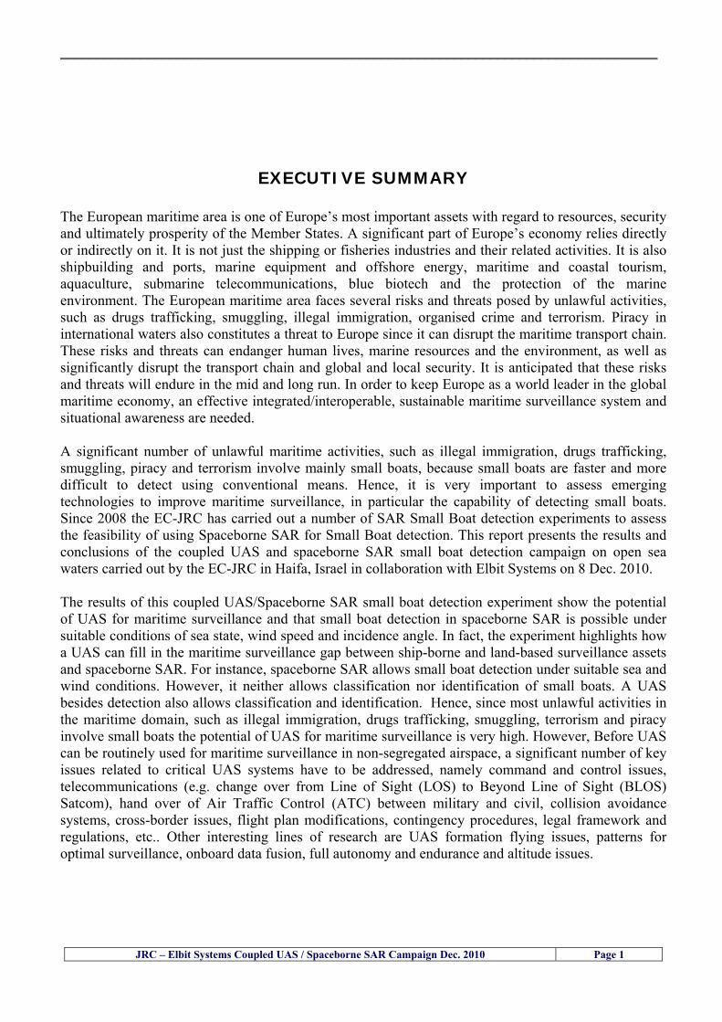
__________________________________________________________________________________
JRC ndash Elbit Systems Coupled UAS Spaceborne SAR Campaign Dec 2010 Page 1
EXECUTIVE SUMMARY The European maritime area is one of Europersquos most important assets with regard to resources security and ultimately prosperity of the Member States A significant part of Europersquos economy relies directly or indirectly on it It is not just the shipping or fisheries industries and their related activities It is also shipbuilding and ports marine equipment and offshore energy maritime and coastal tourism aquaculture submarine telecommunications blue biotech and the protection of the marine environment The European maritime area faces several risks and threats posed by unlawful activities such as drugs trafficking smuggling illegal immigration organised crime and terrorism Piracy in international waters also constitutes a threat to Europe since it can disrupt the maritime transport chain These risks and threats can endanger human lives marine resources and the environment as well as significantly disrupt the transport chain and global and local security It is anticipated that these risks and threats will endure in the mid and long run In order to keep Europe as a world leader in the global maritime economy an effective integratedinteroperable sustainable maritime surveillance system and situational awareness are needed A significant number of unlawful maritime activities such as illegal immigration drugs trafficking smuggling piracy and terrorism involve mainly small boats because small boats are faster and more difficult to detect using conventional means Hence it is very important to assess emerging technologies to improve maritime surveillance in particular the capability of detecting small boats Since 2008 the EC-JRC has carried out a number of SAR Small Boat detection experiments to assess the feasibility of using Spaceborne SAR for Small Boat detection This report presents the results and conclusions of the coupled UAS and spaceborne SAR small boat detection campaign on open sea waters carried out by the EC-JRC in Haifa Israel in collaboration with Elbit Systems on 8 Dec 2010 The results of this coupled UASSpaceborne SAR small boat detection experiment show the potential of UAS for maritime surveillance and that small boat detection in spaceborne SAR is possible under suitable conditions of sea state wind speed and incidence angle In fact the experiment highlights how a UAS can fill in the maritime surveillance gap between ship-borne and land-based surveillance assets and spaceborne SAR For instance spaceborne SAR allows small boat detection under suitable sea and wind conditions However it neither allows classification nor identification of small boats A UAS besides detection also allows classification and identification Hence since most unlawful activities in the maritime domain such as illegal immigration drugs trafficking smuggling terrorism and piracy involve small boats the potential of UAS for maritime surveillance is very high However Before UAS can be routinely used for maritime surveillance in non-segregated airspace a significant number of key issues related to critical UAS systems have to be addressed namely command and control issues telecommunications (eg change over from Line of Sight (LOS) to Beyond Line of Sight (BLOS) Satcom) hand over of Air Traffic Control (ATC) between military and civil collision avoidance systems cross-border issues flight plan modifications contingency procedures legal framework and regulations etc Other interesting lines of research are UAS formation flying issues patterns for optimal surveillance onboard data fusion full autonomy and endurance and altitude issues
__________________________________________________________________________________
JRC ndash Elbit Systems Coupled UAS Spaceborne SAR Campaign Dec 2010 Page 2
1 ndash Introduction
11 ndash Scope
This report presents the key findings of the coupled UAS and Spaceborne SAR Small Boat Detection Campaign led by the EC-JRC and conducted jointly with Elbit Systems in Haifa Israel in December 2010
This study addresses the potential of Unmanned Aerial Systems (UAS) for maritime surveillance
and the feasibility of using UAS as a complementary technology on an operational basis To answer this statement of work a multinational cross-disciplinary consortium with research and
operational expertise in maritime surveillance and Unmanned Aerial Systems (UAS) was assembled with organisations involved in
1- research in maritime surveillance using Spaceborne SAR imagery and in the processing and analysis of SAR imagery as well as coordination and management of maritime surveillance campaigns (European Commission-JRC)
2- experience with Unmanned Aerial Systems (UAS) campaigns (Elbit Systems)
12 ndash Main Objectives
The work was performed with the following main objectives
To acquire hands-on experience with UAS technologies in particular with its possible applications to maritime surveillance
To assess the potential of UAS for maritime surveillance including small boat detection illegal
immigration and drugs trafficking mitigation
To study the feasibility of using UAS as a complementary maritime surveillance technology on an operational basis together with currently used technologies
To identify the main limiting factors preventing the use of UAS in non segregated airspace and
enabling factors that could help to facilitate the operational use of UAS for maritime surveillance
__________________________________________________________________________________
JRC ndash Elbit Systems Coupled UAS Spaceborne SAR Campaign Dec 2010 Page 3
13 ndash Context
Problem Statement ndash The European maritime area is one of Europersquos most important assets with regard to resources security and ultimately prosperity of the Member States A significant part of Europersquos economy relies directly or indirectly on it It is not just the shipping or fisheries industries and their related activities It is also shipbuilding and ports marine equipment and offshore energy maritime and coastal tourism aquaculture submarine telecommunications blue biotech and the protection of the marine environment The European maritime area faces several risks and threats posed by unlawful activities such as drugs trafficking smuggling illegal immigration organised crime and terrorism Piracy in international waters also constitutes a threat to Europe since it can disrupt the maritime transport chain These risks and threats can endanger human lives marine resources and the environment as well as significantly disrupt the transport chain and global and local security It is anticipated that these risks and threats will endure in the mid and long run In order to keep Europe as a world leader in the global maritime economy an effective integratedinteroperable sustainable maritime surveillance system and situational awareness are needed
A significant number of unlawful maritime activities such as illegal immigration drugs trafficking smuggling piracy and terrorism involve mainly small boats because small boats are faster and more difficult to detect using conventional means Hence it is very important to find out the feasibility of using Unmanned Aerial Systems (UAS) on an operational basis as a complementary maritime surveillance technology to currently used maritime surveillance assets such as spaceborne SAR coastal radars ship-borne radars etc
_________________________________________________________________________________
2 ndash Research Method
In order to find out the potential and feasibility of using Unmanned Aerial Systems (UAS) for maritime surveillance including small boat detection a controlled experiment on open sea and along the coast was designed set up and executed The controlled experiment is briefly described next The controlled experiment consisted of a UAS (Hermes 450W from Elbit Systems) flight over the maritime area near the Port of Haifa in Israel at the approximate time of two SAR Satellite overpasses (Radarsat-2 and TerraSAR-X) The Hermes 450 took-off from Haifa in Israel and flew to the area of the experiment The experiment was comprised two phases namely
1) the Coupled UASSpaceborne SAR Small Boat detection and 2) the CONUSE and CONOPS phase
These two phases are described next
21 ndash Coupled UASSpaceborne SAR Small Boat Detection One of the main objectives of this controlled experiment was to find out the potential of using UAS for maritime surveillance in particular to find out if a UAS could fill in the gap between ship borneland based maritime surveillance and spaceborne maritime surveillance in particular the capability of detecting small targets To that end one small boat was deployed on open sea waters a couple of nautical miles southwest of the Port of Haifa The UAS capabilities were then tested The tests comprised flying over the above mentioned area and the detection tracking and classification of the small boat deployed
22 ndash UAS CONUSE and CONOPS Controlled Experiment Another objective of this controlled experiment was to find out the potential of using UAS for maritime surveillance the rationale behind it being testing the capabilities of UAS to detect classify and identify targets on land (eg small boats piers etc) To that end the UAS acquired images of targets of opportunity to test the UAS capabilities The tests comprised flying over the above mentioned area and the detection tracking and classification of targets of opportunity as well as an attempt to detect other moving and stationary targets
__________________________________________________________________________________
JRC ndash Elbit Systems Coupled UAS Spaceborne SAR Campaign Dec 2010 Page 5
3 ndash Experiment Set Up This section describes the experiment set up namely the experiment site selection the SAR Satellite Imagery planning and the partners involved and their roles
31 ndash Experiment Site Selection Bearing in mind that most unlawful maritime activities involving small boats such as illegal immigration drugs trafficking smuggling and terrorist activities can be better mitigated if the small boats are detected at an earlier stage while on open sea the selection of open sea site scenarios for the experiment was an obvious option The open sea trials were carried out a few nautical miles off the coast of Haifa This site was selected because it is under the jurisdiction of the Israeli Air Force which made the authorisation to fly easier to obtain and reduced the risk of accidents involving people since the area is closed to the public For the same reason the tests along the coast also took place in the same area
311 ndash Open Sea Waters Site near Haifa Israel The open seacoastal waters site selected in Haifa near the port of Haifa a few nautical miles off the coast is illustrated in fig1 in Green The UAS flight plan and the Italian Airforce military airbase are also illustrated in fig1
Figure 1 ndash Illustration of the site of the experiment in Haifa Israel The large rectangle in red is the footprint of the TerraSAR-X Stripmap ordered to DLR The small rectangle in red is the footprint of the Radarsat-2 Spotlight spaceborne SAR image ordered to MDA Only the Radarsat-2 image was actually acquired DLR was not able to acquire the TerraSAR-X image due to technical problems
__________________________________________________________________________________
JRC ndash Elbit Systems Coupled UAS Spaceborne SAR Campaign Dec 2010 Page 6
32 ndash SAR Satellite Imagery Planning The Synthetic Aperture Radar (SAR) satellite imagery available at the time the planning was done comprised a Radarsat2 (Spotlight) and a TerraSAR-X (Stripmap) Figure 2 illustrates the TerraSAR-X Stripmap SAR image footprint in red The image was ordered to DLR the German Aerospace Centre but unfortunately it was not possible to acquire it due to technical problems Figure 3 illustrates the footprint of the Radarsart-2 Spotlight SAR image in red
Figure 2 ndash The rectangle in red illustrates de footprint of the TerraSAR-X Stripmap image ordered to DLR Fortunately due to technical problems DLR was not able to acquire this spaceborne SAR image The approximate start date of acquisition was 2010-12-08T15380373
__________________________________________________________________________________
JRC ndash Elbit Systems Coupled UAS Spaceborne SAR Campaign Dec 2010 Page 7
Figure 3 ndash The rectangle in pink illustrates de footprint of the Radarsat-2 Spotlight SAR image ordered to MDA Fortunately due to technical problems DLR was not able to acquire this spaceborne SAR image The approximate start date of acquisition was 2010-12-08T15474000 UTC Table-1 illustrates the SAR satellite images and image modes used in the different days of the experiment
Table 1ndash TerraSAR-X Stripmap and Radarsat2- Spotlight High Resolution 08-Dec-2010 Satellite Evening Satellite Pass 1 TerraSAR-X Stripmap 2010-12-08T15380373 UTC 2 Radarsat-2 Spotlight 2010-12-08T15474000 UTC
__________________________________________________________________________________
JRC ndash Elbit Systems Coupled UAS Spaceborne SAR Campaign Dec 2010 Page 8
The Radarsat2 and TerraSAR-X image modes used in the present experiment will be briefly reviewed in the next paragraphs Radarsat2 - Spotlight Mode ndash The Spotlight Beams are intended for applications which require the best spatial resolution available from the RADARSAT-2 SAR system In this mode the radar operates with the highest sampling rate and so the ground swath coverage is limited to keep data rate within the recorder limits Unlike the other modes Spotlight images are also of fixed size in the along track direction The ser of Spotlight Beams cover any area within the incidence angle range from 20 to 49 degrees Each beam within the set images a swath width of at least 18 km Spotlight images can only be generated in a single polarization which can be either a linear co-polarization (HH or VV) or a linear cross-polarization (HV or VH)
Figure 4 ndash Radarsart2 image modes The Ultrafine and the Spotlight modes have been identified as the most suitable modes for this particular experiment Radarsat2 - Single Beam Mode ndash Single beam mode is a stripmap SAR mode In Single Beam operation the beam elevation and profile are maintained constant throughout the data collection period The following Single Beam modes are available Standard Wide Fine Multi-Look Fine Ultra-Fine Extended High (High Incidence) Extended Low (Low Incidence) Standard Quad Polarization and Fine Quad Polarization We selected Ultra-Fine because it is the best compromise between swath coverage and resolution
__________________________________________________________________________________
JRC ndash Elbit Systems Coupled UAS Spaceborne SAR Campaign Dec 2010 Page 9
Radarsat2 - Ultra-Fine ndash The Ultra-Fine Resolution Beams are intended for applications which require very high spatial resolution In this mode the radar operates with the highest sampling rate and so the ground swath coverage is limited to keep data rate within the incidence angle from 20 to 49 degrees Each beam within the set images a swath width of at least 20 km Ultra-Fine Resolution images can only be generated in a single cross-polarization which can be either a linear co-polarization (HH or VV) or a linear cross-polarization (HV or VH) The standard TerraSAR-X operational mode is the single receive antenna mode from which the following imaging modes can be retrieved High Resolution Spotlight and Spotlight StripMap and ScanSAR The single receive antenna mode uses a chirp bandwidth of up to 300 MHz
Figure 5 ndash Radarsart2 image modes The Ultrafine and the Spotlight modes have been identified as the most suitable modes for this particular experiment The SpotLight (SL) imaging modes use phased array beam steering in azimuth direction to increase the illumination time ie the size of the synthetic aperture This leads to a restriction in the image scene size Thus the scene size is technically restricted to a defined size 10 km x 10 km for the SpotLight mode and 10 km x 5 km (width x length) in the HighResolution SpotLight (HS) mode This sophisticated imaging mode makes it possible to acquire data with up to 1 m resolution in the HighResolution SpotLight mode (acquired with a bandwidth of 300 MHz) and 2 m in the standard SpotLight mode StripMap (SM) is the basic SAR imaging mode as known eg from ERS-1 and other radar satellites The ground swath is illuminated with continuous sequence of pulses while the antenna beam is fixed in elevation and azimuth This results in an image strip with a continuous image quality (in flight direction) StripMap dual polarisation data have a slightly lower spatial resolution and smaller swath than the single polarisation data In StripMap mode a spatial resolution of up to 3 m can be achieved The standard scene size is 30 km x 50 m (width x length) in order to obtain manageable image files however acquisition length is extendable up to 1650 km
__________________________________________________________________________________
JRC ndash Elbit Systems Coupled UAS Spaceborne SAR Campaign Dec 2010 Page 10
33 ndash Partners Involved and their Roles The partners involved in this experiment comprised the European Commission (EC) ndash Joint Research Centre (JRC) and Elbit Systems from Haifa Israel The role of each partner is briefly described next 331 - European Commission (EC) ndash Joint Research Centre (JRC) ndash The main role of the EC-JRC was the planning set up execution and the analysis of the data together with Elbit Systems This comprised
a) the definition of the objectives b) the research methods used c) the ground truth data collection d) the analysis of the data and the conclusions of the experiment
332 ndash Elbit Systems ndash The main role of Elbit Systems comprised
a) the deployment and operation of the boat used as target b) the deployment and operation of the UAS Hermes 450 c) the contacts with the Israeli authorities namely the Israeli Air Force and Civil Aviation
Authority d) the collection of ground truth data e) The analysis of the data and conclusions of the experiment
__________________________________________________________________________________
JRC ndash Elbit Systems Coupled UAS Spaceborne SAR Campaign Dec 2010 Page 11
4 ndash Experiment Execution
41 ndash Modus Operandi The modus operandi of the trial was as follows 1- JRC supplied Elbit Systems with the footprint (frame) of the spaceborne SAR images to be acquired (TerraSAR-X-Stripmap and Radarsat-2 Spotlight) as well as the time of the SAR satellite passes 2- The boat was deployed about 2 nautical miles Southwest of the Port of Haifa The boat was about 12-meter long The boat had a crew of 3 people plus one JRC staff 3- The boat left from the port of Haifa and travelled a couple of nautical miles to reach the test site Once the test site was reached the boat was stationary at the time of the satellite SAR overpass After the satellite overpasses the boat was steered at different speeds to test the tracking capabilities of the UAV
42 ndash Ground Truth Data Collection The ground truth data collected comprised a) the sea state b) Data from the UAS sensors b) the weather conditions and wind speed e) Photos and movies of the boats involved in the experiment
43 ndash Means Involved in the Experiment The means involved in the experiment comprised two satellite SAR images namely a TerraSAR-X-Stripmap and a Radarsat-2 Spotlight and one 12-meter long boat 431 ndash Boat Deployed During the Experiment Figures 6 illustrate the boat deployed as target during the experiment
__________________________________________________________________________________
JRC ndash Elbit Systems Coupled UAS Spaceborne SAR Campaign Dec 2010 Page 12
Figure 6 ndash The 12-meter boat deployed during the experiment at the Port of Haifa Israel 432 ndash Hermes 450 ndash System Overview The Hermesreg UAV system is a mature and operationally proven system with accumulated experience with the Israel Defense Forces operations and with other users worldwide It features a fully redundant architecture leading to a high level of safety and reliability a high level of autonomy modern high performance state-of-the-art payloads and a small logistic footprint Figure 7 shows the main elements of the Hermes UAV System 433 ndash The Air Vehicle Hermesreg 450W is a modern UAV design featuring highly efficient aerodynamics composite structure and a high level of system redundancy and autonomy Its compact size and high maximumempty weight ratio enable very high mission effectiveness delivering potent payloads high endurance and a modest logistic footprint The Hermesreg 450 is in production and has accumulated over 150000 flight hours with the Israeli Air Force and other users around the globe The Hermesreg 450W uses the higher power delivered by the AR802W engine to achieve higher gross weight with the same platform greatly increasing payload and fuel carrying capability a shorter takeoff run and expanded flight envelope
__________________________________________________________________________________
JRC ndash Elbit Systems Coupled UAS Spaceborne SAR Campaign Dec 2010 Page 13
The AR802W engine is a derivative of the AR802 rotary engine with widened rotor and housing The result is a 30 gain in power to nearly 70HP Coupled to an Electronic Fuel Injection system the engine is highly efficient and has improved maintenance figures Following is a summary of the physical characteristics of the Hermes 450W air vehicle is given in Table 2
Table 2 ndash Summary of Hermes 450 main characteristics Physical Characteristics
bull Length 61 m bull Wingspan 105 m bull Fuselage diameter 0508 mm bull Max takeoff weight 550 kg bull Max internal fuel weight (including oil) 115 kg bull Max payload weight 150 kg
Figure 7 ndash Elements of the Hermes UAV System
434 ndash Ground Control Station (GCS) The GCS is a transportable system designed to perform and support all Hermesreg UAV family ground Based activities operational activities These activities include mission planning pre-flight check takeoff and landing UAV flight control mission control payloads and systems control as well as post-mission debriefing An embedded or appended training capability is optional Remote communication of video and telemetry to a C4I center via SATCOM or WAN infrastructure is optional The GCS provides a user friendly comfortable effective and protected environment for carrying out UAV missions
__________________________________________________________________________________
JRC ndash Elbit Systems Coupled UAS Spaceborne SAR Campaign Dec 2010 Page 14
The GCS is housed in a shelter with operator consoles of advanced human engineering design that provide an ergonomic operational environment The shelter is based on the NATO ACE III shelter with a side door As Israelrsquos leading C4I provider Elbit Systems has incorporated Hermesreg GCS advanced C4I capabilities including comprehensive mission planning tactical database management and tactical coordination with supported forces and command elements The Hermesreg GCS is uniquely capable of performing two UAV missions concurrently with two UAVs each of which is controlled via a separate Ground Datalink Terminal (GDT) The Hermesreg GCS requires minimal operating personnel ie mission commander and mission operator
Figure 8 ndash The UAS Hermes 450 Ground Control Station (GCS)
435 ndash The EO Payload The CoMPASS Compact Multi Purpose Advanced Stabilized System is a day and night surveillance system that includes a 3rd generation 3-5 μm zoom FLIR camera a color zoom TV CCD camera and automatic tracking capabilities The CoMPASS enables the following
bull Day and night stabilized LOS observation with capabilities of target detection recognition and identification in various weather conditions
bull Automatic and manual tracking of targets bull Slaving CoMPASS Line of Sight (LOS) to external systems bull LOS information bull Target Laser designationampRanging or only Target Laser Ranging bull Laser Target Marker
__________________________________________________________________________________
JRC ndash Elbit Systems Coupled UAS Spaceborne SAR Campaign Dec 2010 Page 15
CoMPASS the EOIR system for UAV applications is the most advanced payload version of the CoMPASS family featuring reduced weight high degree of modularity and flexibility space-saving packaging and advanced operational and video processing features The CoMPASS based STA Stabilized Turret Assembly is a single LRU housing
bull 3rd generation 3-5 μm FLIR zoom Camera bull Color Zoom TV CCD Camera bull Laser Target Designator bull Laser Target Marker bull Electronic Boards
Figure 9 ndash CoMPASS Stabilized Turret Assembly (STA)
__________________________________________________________________________________
JRC ndash Elbit Systems Coupled UAS Spaceborne SAR Campaign Dec 2010 Page 16
5 ndash Preliminary Data Analysis
51 ndash SAR Satellite Imagery Processing The high resolution spaceborne SAR image was analysed visually because the resolution is good enough to allow visual analysis and the site is too close to the coast which makes automatic processing more difficult and prone to error due to artefacts caused by land targets The Hermes 450 images were also analysed visually
52 ndash Ground Truth Data This section briefly describes the Ground Truth data namely the GPS positions of the boat deployed as target during the experiment a photo of the boat as well as other relevant ground truth data collected
521 ndash GPS coordinates of the boat deployed Table 5 gives the GPS coordinates of the boat deployed during the experiment at the time of the Radarsat-2 satellite overpass Table 3 ndash Ground Truth data collected at the time of the satellite pass (154740 UTC=174740 LT) on 8 December 2010
Date 8 Dec2010 Time 154740 UTC=174740 LT Pass Ascending
SatelliteMode Radarsat-2 Spotlight Polarisation HH
Boats Type Size Latitude Longitude
Elbits 12-meter
Boat
32˚ 51830 N 32deg514980N 32863833deg N
34˚ 57961 E 34deg575766E 34966017deg E
__________________________________________________________________________________
JRC ndash Elbit Systems Coupled UAS Spaceborne SAR Campaign Dec 2010 Page 17
521 ndash HERMES 450 Ground Truth Data Table 4 shows the 12-meter Elbitacutes Boat as detected by the IR sensor of the Hermes 450 Table 4 ndash Hermes 450 Ground Truth Data Date 8 Dec2010 Time 154740 UTC=174740 LT
Platform Hermes 450
UAV Type Size Latitude Longitude
UAV Hermes
450
174730h 3284489947 N
174800h
3285089687 N
174730h 3498564048 E
174800h
3499338667 E
Elbits 12-meter
Boat UAV
Image
32˚ 51830 N 32deg514980N 32863833deg N
34˚ 57961 E 34deg575766E 34966017deg E
53 ndash Weather Conditions and Sea State The weather conditions in Haifa are summarized in Table 5 bellow
Table 5 ndash Wind speed wind direction and Temperature Time (IST) Temp Dew
Point Humidity Pressure Visibility Wind Dir
Wind Speed
Gust Speed Precip Events Conditions
550 PM 210 degC 130 degC 60 1017 hPa - North 111 kmh
31 ms - NA Clear
__________________________________________________________________________________
JRC ndash Elbit Systems Coupled UAS Spaceborne SAR Campaign Dec 2010 Page 18
Figure 10 gives the weather data (Temperature Barometric Pressure Wind Speed and Wind Direction) for Haifa Israel on 8 Dec 2010
Figure 10 ndash Weather data (Temperature Barometric Pressure Wind Speed and Wind Direction) for Haifa Israel on 8 Dec 2010
__________________________________________________________________________________
JRC ndash Elbit Systems Coupled UAS Spaceborne SAR Campaign Dec 2010 Page 19
54 ndash Verification of the Results This section briefly describes the verification of the targets detected in the spaceborne SAR image and in the Hermes 450 UAV using the ground truth data collected during the experiment
541 ndash Overview of the UAV Trajectory and the SAR Imagery Footprint Figure 11 gives an overview of the UAV trajectory the footprint of the SAR imagery and the area of the experiment near the port of Haifa The UAV trajectory is depicted in blue The large red rectangle is the footprint of the TerraSAR-X Stripmap The smaller red rectangle is the footprint of the Radarsat-2 Spotlight image
Figure 11 ndash Google Earth UAV trajectory during the experiment and footprinst of the SAR imagery ordered for the experiment Figure 12 is a zoom in of the previous image which allows a more detailed view of the UAV trajectory and of the port of Haifa Figure 13 is a zoom in of figure 12 It shows in more detail the UAV trajectory during the entire experiment and the port of Haifa in Israel
__________________________________________________________________________________
Figure 12 ndash Zoom in of the previous figure showing a more detailed view of the UAV trajectory and of the port of Haifa in Israel
Figure 13 ndash Zoom in of the previous figure showing a even more detailed view of the UAV trajectory and of the port of Haifa in Israel
JRC ndash Elbit Systems Coupled UAS Spaceborne SAR Campaign Dec 2010 Page 20
__________________________________________________________________________________
JRC ndash Elbit Systems Coupled UAS Spaceborne SAR Campaign Dec 2010 Page 21
542 ndash Targets Detected in the Radarsat-2 Spotlight Image Figure 14 illustrates the position of the Elbitrsquos boat used as target in the experiment at the approximate time of the SAR Satellite pass by 1547 UTC (1747 LT) The small photo of the boat shows the approximate position of the boat The two small planes show the positions of the UAV immediately before and after the SAR Satellite pass
Figure 14 ndash Google Earth positions of the elbitrsquos boat and the UAV (Hermes450) at the approximate time of the SAR Satellite overpass by 174740 UTC Figure 15 shows the corresponding SAR image (Radarsat-2 Spotlight) acquired during the experiment Pins 1 and 2 represent the positions of the UAV before and after the SAR satellite overpass Pin 3 illustrates the position of the Elbitacutes boat deployed at the time of the satellite overpass At this scale the SAR signature of the boat is not distinguishable from the sea clutter background However zooming in the SAR image the SAR signature can clearly be seen as illustrated in figure 12 The SAR image in figure 12 also shows several SAR signatures of large ships in the area at the time of the satellite overpass
__________________________________________________________________________________
JRC ndash Elbit Systems Coupled UAS Spaceborne SAR Campaign Dec 2010 Page 22
Elbit`s Boat
Figure 15 ndash On the background the SAR image with the two UAV positions before and after the satellite overpass (Pin1 and Pin2) and the Elbitacutes Boat position (Pin3) The small window over the SAR image shows a zoom in of the SAR image where the SAR signature of the Elbitacutes Boat can clearly be seen The top right are of the SAR image also shows SAR signatures of several large ships in the area at the time of the SAR satellite overpass Figure 16 shows the corresponding SAR image (Radarsat-2 Spotlight) acquired during the experiment and the UAV IR images of some of the targets Pins 1 and 2 represent the positions of the UAV before and after the SAR satellite overpass Pin 3 illustrates the position of the Elbitacutes boat deployed at the time of the satellite overpass At this scale the SAR signature of the boat is not distinguishable from the sea clutter background However zooming in the SAR image the SAR signature can clearly be seen as illustrated in figure 13 On the top left the UAV IR image of the Elbitrsquos Boat The SAR image in figure 13 also shows several SAR signatures of large ships in the area at the time of the satellite overpass On the centre left the UAV IR image of a large ship On the centre right the UAV IR image of a large ship On the bottom right the UAV IR image of a large ship All the UAV images were acquired at night in complete darkness from altitudes in the order of 5500 meters Nonetheless the quality and detail of the UAV images allows classification of the targets and in some cases the identification As it can be seen the potential of UAV for maritime surveillance is very promising During the experiment the UAV detected all the boats and ships in the area and tracked some of the boatsships to test the tracking capability The capability of detection and tracking targets is a critical capability for maritime surveillance
__________________________________________________________________________________
JRC ndash Elbit Systems Coupled UAS Spaceborne SAR Campaign Dec 2010 Page 23
Elbitacutes Boat
Elbit`s Boat
Figure 16 ndash Zoom-in of figure 15 with the UAV images of some targets On the top left the UAV IR image of the Elbitrsquos Boat On the centre left the UAV IR image of a large ship On the centre right the UAV IR image of a large ship On the bottom right the UAV IR image of a large ship Figure 17 shows a comparison of the SAR and UAV images with an optical photo taken in Haifa Israel a couple of hours before the SAR satellites overpass Most of the large ships were detected in the SAR image and some of these ships can be identified in the optical photo Some of the ships in the photo left the area before the SAR satellites overpass
__________________________________________________________________________________
JRC ndash Elbit Systems Coupled UAS Spaceborne SAR Campaign Dec 2010 Page 24
Figure 17 ndash Photo taken in Haifa Israel a couple of hours before the SAR satellites overpass This phot shows the large ships moored in the area Most of these large ships were detected in the Radarsat-2 image As expected their positions and orientations were slightly different at the time of the satellite overpass
Elbitacutes Boat
Elbit`s Boat
__________________________________________________________________________________
JRC ndash Elbit Systems Coupled UAS Spaceborne SAR Campaign Dec 2010 Page 25
Figure 18 ndash Photo taken in Haifa Israel a couple of hours before the SAR satellites overpass This phot shows the large ships moored in the area Most of these large ships were detected in the Radarsat-2 image As expected their positions and orientations were slightly different at the time of the satellite overpass Figure 18 illustrates the SAR image and the corresponding google earth image of a small pier in the port of Haifa In the SAR image due to several artefacts it is not possible to detect the 7 small boats moored to the small pier The UAR IR image of the same area clearly shows the 7 small boats with impressive detail taking into account that the image was acquired from an altitude of about 5500 meters A zoom in of the same UAV IR image is shown in figure 19 As it can be seen although the image was acquired from an altitude of about 5500 meters the 7 small boats can be clearly seen with enough detail to allow classification of the type of boat A UAV flight at lower altitude would probably giver a lot more detail and eventually allow the identification of the small boats
__________________________________________________________________________________
JRC ndash Elbit Systems Coupled UAS Spaceborne SAR Campaign Dec 2010 Page 26
Figure 19 ndash UAV IR image of a small pier in the port of Haifa Israel where 7 small boats can be seen with enough detail to allow classification This image was acquired from an altitude of about 5500 meters in the dark
__________________________________________________________________________________
55 ndash Quantitative Analysis of the Spaceborne SAR Image In order to allow a quantitative analysis of the data the spaceborne SAR image was calibrated using ESArsquos NEST software package version 4B The input was the SAR image acquired and the output was the Radiometric Calibration (Sigma Naught (σdeg)) expressed in terms of intensity and in decibel (dB) the Radar Brightness (βdeg) and the Radiometric Normalisation (gamma naught (γdeg))
551 ndash Radarsat-2-Spotlight 08Dec2010 (154740 UTC) Haifa Israel Figure 20 illustrates the Intensity band of a subset of the Radarsat-2Spotlgiht image (08Dec2010)
Figure 20 ndash Radarsat-2 Spotlgiht image (08Dec2010) ndash Sigma Naught (Intensity) band
JRC ndash Elbit Systems Coupled UAS Spaceborne SAR Campaign Dec 2010 Page 27
__________________________________________________________________________________
Figure 21 illustrates the Sigma Naught Coefficient of the Radarsat-2 Spotlgiht image (08Dec2010) expressed in terms of intensity and decibel (dB)
Figure 21 ndash Radarsat-2 Spotlgiht image (08Dec2010) - On the left the Sigma Naught (σdeg) (intensity) and on the right the Sigma Naught (σdeg) (dB)
ormalisation amma Naught (γdeg)) of the Radarsat-2 Spotlgiht image (08Dec2010) expressed in dB
-2 Spotlgiht image (08Dec2010) - On the left the Beta Naught (βdeg) and on the right the Gamma Naught (γdeg) (dB)
Figure 22 illustrates the Radar Brightness (Beta Naught (βdeg)) and the radiometric n(G
Figure 22 ndash Radarsat
JRC ndash Elbit Systems Coupled UAS Spaceborne SAR Campaign Dec 2010 Page 28
__________________________________________________________________________________ Figure 23 shows the Sigma Naught (σdeg) in dB after some colour manipulation and the histogram of the Sigma Naught (σdeg) image
Figure 23 ndash Radarsat-2 Spotlgiht image (08Dec2010) - On the top left the Sigma Naught (σdeg) after colour manipulation to enhance the targets and on the top right the corresponding histogram On the bottom we can see the histogram of the image
Table 6 gives the statistics of the Sigma Naught (σdeg) Radarsat-2 Spotlgiht image (08Dec2010) The Sigma Naught (σdeg) range from -72897 dB up to 23465 dB The Mean value is -16855 dB the Median is -16594 dB and the standard deviation is 7077 dB
JRC ndash Elbit Systems Coupled UAS Spaceborne SAR Campaign Dec 2010 Page 29
__________________________________________________________________________________
JRC ndash Elbit Systems Coupled UAS Spaceborne SAR Campaign Dec 2010 Page 30
Table 6 ndash Statistics of the Radarsat-2 Spotlgiht image (08Dec2010) (154740 UTC)
Statistics Values Unit Only ROI-Mask pixels considered Number of pixels total Number of considered pixels Ratio of considered pixels
No 322394283 322394283
1000
Minimum Maximum
-728974609375 234655818939209
intensity_db intensity_db
Mean Median Std-Dev Coefficient of Variation
-16855686580177853 -1659462338617847 707796800831575
07888765273432338
intensity_db intensity_db intensity_db intensity_db
Checking the radar backscattering coefficient of some targets (small boat and some large ships) detected in the Radarsat-2 Spotlight image we get values ranging from -0379 dB up to 23455 dB The analysis of the Sigma Naught values (σdeg) of the targets and the area around the targets shows a significant contrast
56 ndash Summary of the Preliminary Analysis of the Spaceborne SAR Image This experiment involved two spaceborne SAR images namely a TerraSAR-X Stripmap and one Radarsat-2 Spotlight The TerraSAR-X image was not delivered by DLR due to technical problems The Elbitrsquos boat deployed during the experiment was detected in the Radarsat-2 Spotlight image Several other targets including a set of large ships were also detected Table 7 summarises the characteristics of the SAR image acquired and the targets detected
Table 7 ndash List of SAR Satellite Images acquired during the experiment and detected boats ISRAEL (HAIFA)
Date Time Place Satellite Mode Ground Truth Data Detected Boats
08Dec2010 (PM) Haifa - Israel Radarsat-2 Spotlight GPSPhotosMovies 1 small boat deployed + 9 large ships
Table 8 gives the minimum and maximum Sigma Naught (σdeg) of the targets detected in each SAR image
Table 8 ndash Minimum and maximum Sigma Naught (σdeg) of the targets detected in each SAR image
Date Time UTC (LT)Pass Satellite Image Mode Polarisation Sigma Naught (σdeg) Min Max
29Oct2010528UTC(728AM LT) DES Radarsat-2 Spotlight HH --0379 dB 23455 dB The SAR signatures of the boats deployed were very weak Some possible reasons to explain such weak signatures are the sea state the wind speed the incidence angle and the type and materials Another possible reason is the processing at DLR
__________________________________________________________________________________
JRC ndash Elbit Systems Coupled UAS Spaceborne SAR Campaign Dec 2010 Page 31
6 ndash Preliminary Conclusions The analysis of the results of this coupled UASSpaceborne SAR experiment shows a promising potential for the use of UAS for maritime surveillance UAS can be integrated into the airborne building block of maritime surveillance systems to complement the existing assets increase system performance and improve the overall maritime domain awareness The main perceived maritime security and safety threats comprise piracy terrorist and military threats weapons proliferationsmuggling drugs trafficking illegal immigration unlawful use of containers attacks to critical infrastructures and illegal fishing The main maritime security and safety gaps include a lack of technologies with the capability of detecting small targets (eg small boats) a lack of wide area and persistent maritime surveillance a lack of coordination and information sharing limited interoperability a lack of containers security a lack of persistent surveillance of critical infrastructures and early warning systems Unmanned Aircraft Systems (UAS) are an emerging technology with strong potential to mitigate the above mentioned threats by filing in the main maritime security and safety gaps listed earlier For instance the wide range of potential applications of UAS to maritime surveillance includes but is not limited to
bull detection classification and identification of small boats bull persistent maritime surveillance bull use as communications relays bull persistent surveillance of critical infrastructures bull early warning systems bull COMINT and ELINT collection etc
Table 11 illustrates the mapping of maritime securitysafety threats vs gaps and summarises the main potential applications of UAS to maritime surveillance The above mentioned potential applications of UAS to the Maritime Domain will be addressed in turn in more detail next bull Detection classification and identification of small boats ndash The capability of detecting classifying and identifying small targets (eg small boats) is among the key technologies required to improve maritime domain awareness This capability is critical to mitigate piracy illegal immigration drugs trafficking weapons smuggling illegal fishing terrorism and critical infrastructure Unmanned Aircraft Systems (UAS) provide this capability more efficiently and at a lower cost than any other existing technology bull Persistent maritime surveillance ndash With the continuous improvements of UAS technologies such as platforms sensors collision avoidance systems command and control systems telecommunications etc UAS are increasing their autonomy endurance and flexibility These characteristics are very important for persistent maritime surveillance UAS can be launched from land ships aircraft and technologies to launch UAS from submarines are currently under development UAS have distinct advantages over other existing technologies for persistent maritime surveillance in terms of autonomyendurance (the Global Surveyor has an autonomy of 1 week) cost (eg as the autonomy of UAS increases the number of staff required to operate UAS decreases) risk (eg if the UAS crashes the crew is not at risk) flexibility (eg they can be launched from a ship reducing the time to reach potential threats) etc
__________________________________________________________________________________
JRC ndash Elbit Systems Coupled UAS Spaceborne SAR Campaign Dec 2010 Page 32
bull Communications relays ndash UAS are being used as communication relays mainly in military context but have the potential to play a similar role in Civil context in several situations such as to replace satellite communications or as a redundant system over any location on Earth The main advantages of using UAS as communication relays is that airborne communication relays mitigate kinetic and noise jamming threats to satellite communications uplinks by providing an alternative set of links either directly to surface-based terminals or to satellites beyond the range of threats They are less susceptible to noise jamming threats than satellites because an adversary has to detect geolocate and track the airborne asset and operate within line of sight of the receive antenna main beam bull Persistent surveillance of critical infrastructures ndash The security of critical infrastructures such as nuclear power plants refineries ports etc requires persistent surveillance UAS can play an important role in providing persistent surveillance over critical infrastructures and over a wide area around the critical infrastructure Some advantages of UAS over other existing technologies such as ground-based assets (eg video cameras alarm systems manned aircraft etc) comprise the security of the UAS (eg hardly can be damaged or switched off as any ground-based asset) the area covered by a UAS (eg it is larger than the area covered by any ground-based asset) the cost (eg UAS is cheaper than manned aircraft with similar capability) etc bull Early warning systems ndash UAS have the potential to be used as part of an integrated system of systems for early warning A UAS can provide information about a given area at a fraction of the cost of alternative means Formation flying of UAS can cover a wide maritime area It is reasonable to assume that in a foreseeable future with the advent of UAS with increased autonomy the operations cost of UAS will likely decrease making them increasingly more attractive bull COMINT and ELINT collection ndash SIGNal INTelligence (SIGNINT) can be divided into two categories namely COMINT and ELINT COMINT stands for Communication Intelligence and ELINT for Electronic Intelligence Collection of COMINT is passive Exploitation of COMINT requires a human operator which implies COMINT UAS are suitable for COMINT and ELINT collection in different scenarios The relatively reduced amount of data collected and analysed during this experiment and the lessons learned do not allow drawing final conclusions about the feasibility of using Unmanned Aerial Systems (UAS) for maritime surveillance However this experiment allowed hands-on experience with UAS technologies and significantly improved the awareness for its applications to maritime surveillance and related issues involved including its potential the feasibility as well as the limiting and enabling factors These different aspects will now be analysed in turn in the next sections Table 11 illustrates the mapping of the main maritime security threats and gaps as well as the main priorities in terms of the different technologies involved in maritime surveillance For each maritime threat the technologies required to fill in each gap is indicated and its priority is expressed in a range of numbers (1 to 3 1 = Maximum Priority 2 = Medium Priority 3 = Low Priority) and colours (Red = Maximum Priority Orange = Medium Priority Green = Low Priority) The main technologies involved in maritime surveillance are listed on the bottom of figure 4 and are reproduced here for convenience of the reader 1- Reporting Systems 2- Sensors 3- Platforms 4- Communications 5- Data Fusion amp Sharing 6- Intelligence and 7- Databases For example the mitigation of the main threat Piracy requires filling in several maritime security gaps (eg lack of persistent surveillance lack of wide-are maritime surveillance lack of small boat detection lack of Early Warning Systems and lack of Information Sharing with maximum priority (1- Red) and among the required technologies listed are UAS LTAAV GEO-HR etc Concerning the remaining two gaps (Limited Interoperability and Containers Security) they are less relevant to mitigate Piracy hence the priority for Limited Interoperability is 2-Orange and for Containers Security is 3- Green
__________________________________________________________________________________ Table 9 ndash The Main Maritime Security and Safety Threats vs Gaps and the technologies that can be used to mitigate them
Maritime Security Main Threats GapsGapsrarr
darrThreats
Lack o f Risk As sessmentCapab ility
La ck of Persiste nt
Surveilla nce
La ck of Wid e-Area su rve illanc e
La ck of Small Boat De tecti on
Lack o f Earl y Warn ing Sys tems
L ack of In forma tion
Sh arin g
L imi ted In terop era bility
Lac k of Co ntai ners
Se cur ity
bull PiracyUAS LTAVG EO-
HR + UAS LT AVGEO-
HR + SAR GEO-HR
+ UAS USV LTAV
+ UAS LTAV
+ Coord in ationamp Sharing +
Inter opera bilityOptimisation +
1 2 3 5 6 7 1 2 3 5 6 7 1 2 3 5 6 1 2 3 123456 4567 1234567 1234567
bull Terro rismUAS LTAVG EO-
HR + UAS L TAV GEO-HR +
SAR AISGEO-HR +
UAS USV LTAV+
Intelligence+
Inte lligen ce+
Inter opera bilityOptimisation +
Intelligence+
1 2 3 5 6 7 1 2 3 5 6 1 2 3 5 6 1 2 3 123456 4567 1234567 1234567
bull Wea pon s ofM ass Dest ru ctio n Smugg ling
UAS LTAVG EO-HR +
UAS LT AVGEO-HR +
SAR AIS+
UAS USV LTAV+
Intelligence+
Inte lligen ce+
Intelligence+
Intelligence+
1 2 3 5 6 7 1 2 3 5 6 1 2 3 5 6 1 2 3 123456 4567 1234567 1234567
bull Drug sTraffic king
UAS LTAVG EO-HR +
UAS LT AVGEO-HR +
SAR AIS+
UAS USV LTAV+
Intelligence+
Inte lligen ce+
Intelligence+
Intelligence+
1 2 3 5 6 7 1 2 3 5 6 1 2 3 5 6 1 2 3 123456 4567 1234567 1234567
bull Illega lImmigratio n
UAS LTAVG EO-HR +
UAS LT AVGEO-HR +
SAR AIS+
UAS USV LTAV+
Intelligence+
Inte lligen ce+
Intelligence+
Intelligence+
1 2 3 5 6 7 1 2 3 5 6 1 2 3 5 6 1 2 3 123456 4567 1234567 1234567
bull Critic alI nfrastruc tureSecu rit y
UAS LTAVG EO-HR +
UAS LT AVGEO-HR +
SAR AIS+
UAS USV LTAV+ + Inte lligen ce
+ Intelligence
+ Intelligence
+
1 2 3 5 6 7 1 2 3 6 1 2 3 5 6 1 2 3 123456 4567 1234567 1234567
bull Illega lFish ing
UAS LTAVG EO-HR +
AI S+SAR UASLTAV +
SAR AIS GEO-HR+
UAS USV LTAV+
Intelligence+
Inte lligen ce+
Intelligence+
1 2 3 5 6 7 1 2 3 5 7 1 2 3 5 6 1 2 3 123456 4567 1234567
bull Un lawf ul Use of Co nta iners
(Secur ity)
UAS LTAVG EO-HR +
GPS Tr acking+
Intelligence+
Inte lligen ce+
GPS Int rusion Det ection Se al
1 2 3 5 6 7 4 6 7 1 2 3 5 6 1 2 3 123456 4567 1234567 1234567
(-) Priority (+) Not Rel evant
SURVEILLANCETECHNOLOGIES
1- Reporti ng Systems
2 -Sensors 3 -P latforms 4 - Communications 5- Data Fusionamp Sharing
6 -I ntelli gence 7 -Databases
JRC ndash Elbit Systems Coupled UAS Spaceborne SAR Campaign Dec 2010 Page 33
__________________________________________________________________________________
JRC ndash Elbit Systems Coupled UAS Spaceborne SAR Campaign Dec 2010 Page 34
61 ndash Hands-on experience with UAS technologies and its applications to maritime surveillance This coupled UASSpaceborne SAR campaign was a unique opportunity to acquire further handsndashon experience with UAS technologies and learn about the main issues related to its applications to maritime surveillance From the planning phase up to the execution of the UAS flight and landing there are several factors that need to be carefully analysed and taken into account A summary of the main issues identified in this experiment is given next 1- Selection of the Experiment Area Authorisation to Fly ndash For the time being UAS can only be flown in restricted areas usually under control of national authorities often the military This is due to the risks that a UAS can pose to human life and property In the present case an area under the authority of the Israeli Civil Aviation Authority was selected The authorisation to fly was not easy to obtain because the selected area is under the authority of the Civil Aviation Authority Figure 24 indicates the area of the experiment in Haifa Israel 2- UAS Communications Issues ndash The Hermes 450 was flown in Line-of-Sight (LOS) since it was close to the coast For BLOS (Beyond Line-of-Sight) operation satellite communications are required 3- Synthetic Aperture Radar (SAR) ndash The specific model Hermes 450W used in the experiment had no SAR sensor installed However a SAR sensor can be installed A SAR sensor is important for maritime surveillance since it allows 247 operations regardless of the weather conditions 4- Automatic Identification System (AIS) Receiver ndash The Hermes 450 used in this experiment was not equipped with an AIS receiver For maritime surveillance operations an AIS receiver is a very important tool since it allows the automatic identification of most ships allowing the UAS to concentrate on non-identified ships
__________________________________________________________________________________
Figure 24 ndash The area of the experiment is indicated by the GPS Trajectory of the UAV
62 ndash Potential of UAS for Maritime Surveillance UAS technologies are relatively recent and involve a wide range of fields spanning from aeronautics and sensors technologies to satellite communications and other engineering disciplines Innovations in each of the fields involved are emerging by the day UAS still have a long way to go before they become mature and their use fully operational For the time being UAS are mainly used for military applications However a large number of non-military UAS applications have been identified by stakeholders and there are several studies and demonstration flights foreseen for the near future Maritime surveillance is one of the most challenging and promising fields of application of UAS The challenges are due to the very demanding conditions under which the UAS must operate over sea and the requirements for safe operation
JRC ndash Elbit Systems Coupled UAS Spaceborne SAR Campaign Dec 2010 Page 35
__________________________________________________________________________________
JRC ndash Elbit Systems Coupled UAS Spaceborne SAR Campaign Dec 2010 Page 36
The present UAS experiment has unveiled some of the potential of UAS for maritime surveillance The UAS tests performed during this experiment include
1 ndash Detection of a Small rubber Boat and a Fishing Ship 2 ndash Tracking of a Small Boat and a Fishing Ship 3 ndash Classification of a Small Boat and a Fishing Ship 4 ndash Identification of a Small Boat and a Fishing Ship 5 ndash Detection and Tracking of People on the Beach
Despite the operational requirement that prevented the UAS from flying bellow 3km the experiment has confirmed the capability of UAS for small boat detection tracking and classification as well as the capability for people detection and tracking Concerning the identification of the targets the characteristics of the images acquired during this mission suggest that flying at lower altitudes the UAS images would allow the identification of the targets The UAS images can be seen from Figure 15 to 20
621 ndash Advantages of UAS for maritime Surveillance Some of the advantages of using UAS for maritime surveillance have been described in the literature and are summarized bellow
1- One potential benefit of UAS is that they could fill in a gap in current maritime surveillance by improving coverage
2- The range of UAS is a significant asset when compared to border agents on patrol or stationary surveillance equipment
3- Eletro-Optical InfraRed (EOIR) sensors (cameras) can identify small size objects from very high altitudes (high resolution)
4- UAS can provide precise and near-real-time imagery to a ground control operator who would then disseminate that information so that informed decisions regarding the deployment of border patrol agents can be made quickly
5- Long endurance UAS used along the border can fly for more than 30 hours up to several days without having to refuel compared with manned helicopterrsquos average flight time of just over 2 hours
6- The ability of UAS to loiter for prolonged periods of time has important operational advantages over manned aircraft
7- The longer flight times of UAS means that sustained coverage over a previously exposed area may improve maritime security
8- The range of UAVs is a significant asset when compared to border agents on patrol or stationary surveillance equipment Nevertheless the extended range and endurance of UAVs may lessen the burdens on human resources at the borders
9- UAS accidents do not risk the lives of pilots as do the helicopters and aircraft currently used by Coast Guards for border patrolling
__________________________________________________________________________________
JRC ndash Elbit Systems Coupled UAS Spaceborne SAR Campaign Dec 2010 Page 37
622 ndash Possible Drawbacks of using UAS for maritime Surveillance UAS also have disadvantages some of them are briefly described next
1- There have been concerns regarding the high accident rate of UAS which can be multiple times higher than that of manned aircraft Because UAS technology is still evolving there is less redundancy built into the operating system of UAS than of manned aircraft and until redundant systems are perfected mishap rates are expected to remain high
2- If control systems fail in a manned aircraft a well-trained pilot is better positioned to find the source of the problem because of hisher physical proximity If a UAS encountered a similar system failure or if a UAS landing was attempted during difficult weather conditions the ground control pilot would be at a disadvantage because he or she is removed from the event Unlike a manned pilot the remote pilot would not be able to assess important sensory information such as wind speed
3- Inclement weather conditions can also impinge on a UAS surveillance capability especially UAS equipped with only an EO camera and Forward Looking Infrared Radar (FLIR) because cloudy conditions and high humidity climates can distort the imagery produced by EO and FLIR equipment The effects of extreme climatic or atmospheric conditions on sensors reportedly can be mitigated with the outfit of one synthetic aperture radar (SAR) system and a moving target indicator (MTI) radar However adding SAR and MTI to a UAS platform would increase the costs associated with using UAS
4- Depending on the type of UAS the costs of operating a UAS can be higher than the costs of operating a manned aircraft This is because some types of UAS require a significant amount of logistical support and specialized operator and maintenance training Operating one UAS may require a crew of up to 20 support personnel The high comparative costs of operating some sophisticated types of UAS may be offset somewhat by their comparatively lower unit costs
63 ndash Main Limiting Factors Preventing the Use of UAS Several pre-requisites must be satisfied to render the UAS a viable cost-effective and regulated alternative to existing resources Major civil and commercial market barriers include
Single European Sky Sense and Avoid technologies Command and Control Technologies Reliability Communications (Bandwidth LOS BLOS)
Lack of airspace regulation that covers all types of UAV systems (encompassing lsquosense and avoidrsquo airspace integration and airworthiness issues)
Affordability - price and customization issues (eg commercial off-the-shelf open modular architecture) Lack of efforts to establish joint customer requirements (although this is gradually changing) Liability for civil operation Capacity for payload flexibility Lack of sufficient secure non-military frequencies for civil operation Perceived reliability (eg vehicle attrition rate vs manned aircraft) Operator training issues Recognitioncustomer perception of the UAV market Technology developments for multi-mission capability
__________________________________________________________________________________
64 ndash UAS Key Enabling Technologies Figure 25 illustrates the components of a typical UAV System showing some of the capabilities needed and the enabling technologies required for performing a given mission Any UAV mission involves many capabilities and technologies Due to the depicted system complexity the main key players such as the US Department of Defense (DoD) and other agencies have started to use the term Unmanned Aerial System (UAS) in place of UAV
Figure 25 ndash Unmanned Aerial Vehicle System Enabled by Autonomous Mission Management Reliable Flight Systems Navigation Accurate Systems Terrain Avoidance Power and Propulsion Some UAS key enabling technologies are listed below
Autonomous Mission Management Collision Avoidance Intelligent System Health Monitoring
Reliable Flight Systems Sophisticated Contingency Management Intelligent Data Handling and Processing Over-the-Horizon Communication Network-Centric Communication Open Architecture Power and Propulsion Navigation Accurate System Technology Enhanced Structures
JRC ndash Elbit Systems Coupled UAS Spaceborne SAR Campaign Dec 2010 Page 38
__________________________________________________________________________________
JRC ndash Elbit Systems Coupled UAS Spaceborne SAR Campaign Dec 2010 Page 39
Table 12 gives a more detailed description of other critical technologies for emerging autonomous UAV systems both civil and military Most of the technologies mentioned in Table 12 apply both to civil and military UAV systems Table 10 ndash Key Enabling Technologies (from SG75 study on autonomous systems)
Critical Technologies Decision Making Software
bull Fuzzy-based decision making bull Knowledge-based system bull Case-based reasoning bull Self-learning techniques bull Decision tree evaluation bull ReasoningInferring bull Probabilisticstochastic reasoning
Prediction Algorithms bull Predictive pathintent algorithms bull Short reaction algorithm bull Effectiveness evaluation
Status Assessment Software bull Internal status analysis bull Self-orientation
Situation Analysis Software bull Situation analysis bull Environmental analysis bull External status analysis
Modelling Software bull Air vehicle modelling algorithms bull Sensor modelling algorithms bull Scenario generation bull Threat system modeling bull Attack simulation bull Mission success optimisation model bull Simulation
Sensor Processing Software bull Sensor fusion bull Area of interest identification bull Automatic target recognition
Adaptive and Self-learning Systems bull Failure self-compensation
Attack Planning Software bull Attack plans and tactical alternatives bull Plan change impact identification
Weapon Engagement Procedure Software bull Weapon engagement algorithms
Mission Plan Update Software bull Route planning system bull Payload plan management system bull Mission Success Optimisation model
Path Optimisation Software bull Optimal trajectory planning bull Path Optimisation System
Targeting Software bull Target tracking bull Target prioritisation
Platform Technologies bull Obstacle detection and avoidance (airborne) bull Obstacle detection and avoidance (ground) bull Improved autopilot bull Speech recognition
Figure 26 summarises system element designs needed to transition from current to next-generation autonomous UAV systems for civilian and military UAS
__________________________________________________________________________________
Figure 26 ndash System Element Designs Needed to Transition from Current to Next-Generation Autonomous UAV Systems These new paradigms are a combination of system attributes and technological capabilities For instance the data fusion secure anti-jam and coordinated multi-vehicle control require technological development as well as specific system development to bring full maturity to unmanned systems Finally very small Micro UAVs (MAVs) and relatively large sophisticated UCAV systems are examples of the range of UAVs that are applying the new platforms payloads onboard processing communications etc to create next generation automated UAVs It is with these new platforms payloads etc that both UCAVs and MAV will be able to address similar operational challenges including
Mixed operation with other assets bull Deconfliction collision avoidance C4I integration
Operation over populated areas bull Safety issues Need to reduce reliance on communications bull UCAV ndash countermeasures bull MAV ndash limited size and power bull Limited line of sight environment Need a fully integrated system bull MAV propulsionpower generation still critical bull Operator machine interface critical bull All weather operations bull Survivability
JRC ndash Elbit Systems Coupled UAS Spaceborne SAR Campaign Dec 2010 Page 40
__________________________________________________________________________________
JRC ndash Elbit Systems Coupled UAS Spaceborne SAR Campaign Dec 2010 Page 41
65 ndash Mission Readiness
651 ndash Mission Readiness Summary This section summarises civil UAV mission readiness The purpose of Mission Readiness is to assess the readiness status of the different technologies involved in UAS In the present case this civil UAV mission readiness based on technology maturation forecasts that meet or exceed the desired or required capabilities identified by the user community Figure 27 summarises the mission readiness time forecasts for the different technologies The technologies annotated with an asterisk () are shown within the figure with maturation forecasts based on development targets expressed in the US Department of Defencesrsquo UAV Roadmap document The purpose of the chart is to be able to identify when the capability to fly a particular mission can be expected as a function of time The left-most end is the least probable and the right end the most probable timeframe
Figure 27 ndash Technology Maturation Summaries in Terms of Mission-Derived Capabilities
__________________________________________________________________________________
JRC ndash Elbit Systems Coupled UAS Spaceborne SAR Campaign Dec 2010 Page 42
66 ndash Small Boat Detection in SAR Satellite Imagery The use of spaceborne SAR imagery for small boat detection requires additional small boat detection experiments under different conditions using different methods It is not possible to draw final conclusions based on a limited number of small boat detection experiments which are not representative of the multiple possible scenarios
67 ndash Limitations of current State-of-the-Art SAR Satellite technology The main limitations of current State-of-the-Art spaceborne SAR imagery for maritime surveillance in particular aimed at small boat detection are 1 - SAR satellites repeat cycles do not allow the coverage of the same area at the required time intervals Constellations of SAR satellites could be a solution 2 - The conflict between resolution and image swath High resolution is required to detect small boats However the high resolution images have small swaths Maritime surveillance with high resolution images would require a large number of images to cover wide maritime areas which is very expensive and for the time being technically not feasible Intelligence data can play an important role by indicating an approximate position of suspicious non cooperative targets therefore reducing the surveillance area which can then be imaged using high resolution images 3- Spaceborne high resolution SAR imagery acquisition times are long enough to allow significant motion of the target during the acquisition time degrading the quality of the image Further research efforts are needed to develop new sensors and platforms As far as sensors are concerned shorter integration times are needed to prevent the blurring effect caused by the motion of the targets Regarding the platforms more platforms are needed to allow lower repeat cycles and improved coverage
__________________________________________________________________________________
JRC ndash Elbit Systems Coupled UAS Spaceborne SAR Campaign Dec 2010 Page 43
7 ndash Plans for Future Work The controlled experiments carried out by the EC-JRC together with Elbit Systems in Haifa-Israel comprised the deployment of a UAS (Hermes-450) and one small 12-meter boat A Radarsat-2 Spotlight image was acquired and several images collected by the Hermes-450 The experiment unveiled the potential of UAS for maritime surveillance in particular for detection tracking classification and possible identification of small targets The UAS was able to detect track and classify small targets such as small boats For low UAS altitude flights identification may be possible in some cases The small 12-meter boat was detected in the spaceborne SAR image The small boat detection trials carried out by the JRC were very successful since most small boats deployed during the experiments were detected in different sea states wind speeds and geographical locations The several small boat detection campaigns conducted by the EC-JRC seem to suggest that the probability of detection of small boats in spaceborne SAR images strongly depends on factors such as the sea state the wind speed the type of boat (shape and materials) the weather conditions among other factors The results of the experiments conducted thus far are not enough to draw final conclusions about the feasibility of using spaceborne SAR imagery for small boat detection However the experiments have an overall positive outcome because they indicate that under suitable sea state and wind speed conditions it is possible to detect small boats using spaceborne SAR The estimation of the probability of detection of small boats in spaceborne SAR images requires a large number of experiments under different circumstances (eg sea state wind speed characteristics of the targets image type and mode etc) Future plans include additional UAS experiments to asses its potential for maritime surveillance
Acknowledgements ndash The authors would like to express their gratitude to Elbit Systems for their cooperation logistical support and assets deployed without which the present coupled UASSAR Satellite Small Boat Detection Campaign would have not been possible
__________________________________________________________________________________
JRC ndash Elbit Systems Coupled UAS Spaceborne SAR Campaign Dec 2010 Page 44
REFERENCES [1] Elbit Systems ldquoUAV Elbit Systems Proposal for Unmanned Aerial Vehicle (UAV) flight to
collect Ground Truth data during a Maritime Surveillance Campaign and demonstrate UAV capabilities for Maritime Surveillancerdquo 2010
[2] ndash Cheryl Yuhas Suborbital Science Program Manager NASA Science Mission Directorate ldquoEarth Observations and the Role of UAVs A Capabilities Assessment Version 11rdquo Civil UAV Assessment Team httpwwwnasagovcentersdrydenresearchcivuavindexhtml August 2006
[3] ndash Document NIAG (SG75) NATO Industrial Advisory Group Study Group 75 Pre-Feasibility Study on UAV Autonomous Operations 2004
[4] ndash United States Department of Defence (DoD) Directive 50001 ldquoThe Defense Acquisition Systemrdquo and DoD Instruction 50002 ldquoOperation of the Defense Acquisition Systemrdquo
[5] ndash Mr James Ramage Mr Massimo Avalle Dr Erik Berglund Dr Luigi Crovella Mr Robert Frampton Dr Uwe Krogmann Mr Christian Ravat Mr Mike Robinson Dr Axel Schulte Dr Scott Wood ldquoRTO-TR-SCI-118 - Automation Technologies and Application Considerations for Highly Integrated Mission Systemsrdquo RTO-TR-SCI-118 AC323(SCI-118)TP204 January 2009
[6] Victor MG Silva Gilles Jurquet Gabriel Marchalot Maria TG Calzado Txema Soroa Juan Sancho Adam Koubek Harm Greidanus and Claudio Savarino ldquoWide Maritime Area Airborne Surveillance (WIMA2S) WP5 Final Reportrdquo WIMAAS WP5 FP7 Project 2008-2011 - ISBN-978-92-79-22801-8 (print) 978-92-79-22802-5 (PDF) ISSN-1018-5593 (print) 1831-9424 (online) EC-JRC Scientific Report JRC 70093 2012
[7] Victor MG Silva and Harm Greidanus ldquoSpaceborne SAR Small Boat Detection Campaign in Portugal and Spainrdquo EUR 25281 EN ISBN 978-92-79-22553-6 ISSN 1831-9424 (online) EC-JRC Scientific Report JRC68160 2012
[8] Goncalves Da Silva V Van Wimersma Greidanus H Hejmanowska B Loudjani P ldquoUAS Applications With Societal Benefits ndash JRCrsquos UAS-Related Activitiesrdquo 2011-2012 UAS Yearbook - UAS Unmanned Aircraft Systems - The Global Perspective 9 (9) 2011 p 127-129 JRC66600
[9] Goncalves Da Silva V Van Wimersma Greidanus H ldquoSmall boat detection using TerraSAR-X and Radarsat2 satellite imageryrdquo 4th TerraSAR-X Science Team Meeting 14 February 2011 DLR Oberpfaffenhofen (Germany) German Aerospace Center (DLR) (Organiser) 2011 JRC63663
[10] V Silva Harm Greidanus ldquoJRC - SAR Satellite Small Boat Detection Campaign - Portoroz ndash Sloveniardquo - ISBN-13 978-92-79-21476-9 ISSN (online) 1831-9424 EC-JRC Scientific Report JRC66835 2011
[11] V Silva Harm Greidanus ldquoJRC - SAR satellite small boat detection campaign - Algarve Portugalrdquo - ISBN-13 978-92-79-21265-9 ISSN (online) 1831-9424 ISSN (print) 1018-5593 EC-JRC Scientific Report JRC66631 2011
[12] ndash Goncalves Da Silva V Van Wimersma Greidanus H ldquoJRC-Frontex Spaceborne SAR Small Boat Detection Campaign ndash Italy amp Spainrdquo - ISBN-13 978-92-79-22213-9 ISSN (online) 1831-9424 EC-JRC Scientific Report JRC67517 2011
[13] - PW Vachon SJ Thomas J Cranton HR Edel and MD Henschel Validation of ship detection by the RADARSAT synthetic aperture radar and the Ocean Monitoring Workstation Canadian Journal of Remote Sensing 26(3)200ndash212 2000
[14] - Crisp D (2004) The state-of-the-art in ship detection in Synthetic Aperture Radar imagery DSTO Information Sciences Laboratory Australia
[15] - Joint Research Centre (JRC) of the European Community mdash IMPAST and DECLIMS web site httpintelligencejrcceceuintmarinefishindexhtm
[16] - McCandless SW Jackson CR (2004) Principles of Synthetic Aperture Radar Synthetic Aperture Radar Marine Users Manual NOAA Washington pp 1-23
[17] - Greidanus H (2008) Satellite Imaging for Maritime Surveillance of the European Seas Remote Sensing of the European Seas 343-358
European Commission
EUR 25346 EN --- Joint Research Centre --- Institute for the Protection and Security of the Citizen
Title JRC --- Elbit Systems Coupled UAS and Spaceborne SAR Campaign in Israel
Authors Victor MG Silva Harm Greidanus
Luxembourg Publications Office of the European Union
2012 --- v+44 pp --- 210 x 297 cm
EUR --- Scientific and Technical Research series --- ISSN 181-9424 (online) ISSN 1018-5593 (print)
ISBN 978-92-79-25020-0
doi10278828527
Abstract The European maritime area is one of Europersquos most important assets with regard to resources security and ultimately
prosperity of the Member States A significant part of Europersquos economy relies directly or indirectly on it It is not just the
shipping or fisheries industries and their related activities It is also shipbuilding and ports marine equipment and offshore
energy maritime and coastal tourism aquaculture submarine telecommunications blue biotech and the protection of the
marine environment The European maritime area faces several risks and threats posed by unlawful activities such as drugs
trafficking smuggling illegal immigration organised crime and terrorism Piracy in international waters also constitutes a threat
to Europe since it can disrupt the maritime transport chain These risks and threats can endanger human lives marine resources
and the environment as well as significantly disrupt the transport chain and global and local security It is anticipated that these
risks and threats will endure in the mid and long run In order to keep Europe as a world leader in the global maritime economy
an effective integratedinteroperable sustainable maritime surveillance system and situational awareness are needed
A significant number of unlawful maritime activities such as illegal immigration drugs trafficking smuggling piracy and
terrorism involve mainly small boats because small boats are faster and more difficult to detect using conventional means
Hence it is very important to find out the feasibility of using Unmanned Aerial Systems (UAS) for small boat detection tracking
classification and identification as well as to study the potential of UAS for maritime surveillance Since 2010 the EC-JRC has
carried out a number of UAS maritime surveillance campaigns to study the potential of UAS for maritime surveillance in
particular for small boat detection This report presents the results and conclusions of the JRC --- Elbit Systems Coupled UAS and
Spaceborne SAR campaign carried out in Dec 2010 in Haifa Israel
As the Commissionrsquos in-house science service the Joint Research Centrersquos mission is to provide EU policies with independent evidence-based scientific and technical support throughout the whole policy cycle Working in close cooperation with policy Directorates-General the JRC addresses key societal challenges while stimulating innovation through developing new standards methods and tools and sharing and transferring its know-how to the Member States and international community Key policy areas include environment and climate change energy and transport agriculture and food security health and consumer protection information society and digital agenda safety and security including nuclear all supported through a cross-cutting and multi-disciplinary approach
LB-NA-25346-EN
-N
__________________________________________________________________________________
JRC ndash Elbit Systems Coupled UAS Spaceborne SAR Campaign Dec 2010 Page 3
13 ndash Context
Problem Statement ndash The European maritime area is one of Europersquos most important assets with regard to resources security and ultimately prosperity of the Member States A significant part of Europersquos economy relies directly or indirectly on it It is not just the shipping or fisheries industries and their related activities It is also shipbuilding and ports marine equipment and offshore energy maritime and coastal tourism aquaculture submarine telecommunications blue biotech and the protection of the marine environment The European maritime area faces several risks and threats posed by unlawful activities such as drugs trafficking smuggling illegal immigration organised crime and terrorism Piracy in international waters also constitutes a threat to Europe since it can disrupt the maritime transport chain These risks and threats can endanger human lives marine resources and the environment as well as significantly disrupt the transport chain and global and local security It is anticipated that these risks and threats will endure in the mid and long run In order to keep Europe as a world leader in the global maritime economy an effective integratedinteroperable sustainable maritime surveillance system and situational awareness are needed
A significant number of unlawful maritime activities such as illegal immigration drugs trafficking smuggling piracy and terrorism involve mainly small boats because small boats are faster and more difficult to detect using conventional means Hence it is very important to find out the feasibility of using Unmanned Aerial Systems (UAS) on an operational basis as a complementary maritime surveillance technology to currently used maritime surveillance assets such as spaceborne SAR coastal radars ship-borne radars etc
_________________________________________________________________________________
2 ndash Research Method
In order to find out the potential and feasibility of using Unmanned Aerial Systems (UAS) for maritime surveillance including small boat detection a controlled experiment on open sea and along the coast was designed set up and executed The controlled experiment is briefly described next The controlled experiment consisted of a UAS (Hermes 450W from Elbit Systems) flight over the maritime area near the Port of Haifa in Israel at the approximate time of two SAR Satellite overpasses (Radarsat-2 and TerraSAR-X) The Hermes 450 took-off from Haifa in Israel and flew to the area of the experiment The experiment was comprised two phases namely
1) the Coupled UASSpaceborne SAR Small Boat detection and 2) the CONUSE and CONOPS phase
These two phases are described next
21 ndash Coupled UASSpaceborne SAR Small Boat Detection One of the main objectives of this controlled experiment was to find out the potential of using UAS for maritime surveillance in particular to find out if a UAS could fill in the gap between ship borneland based maritime surveillance and spaceborne maritime surveillance in particular the capability of detecting small targets To that end one small boat was deployed on open sea waters a couple of nautical miles southwest of the Port of Haifa The UAS capabilities were then tested The tests comprised flying over the above mentioned area and the detection tracking and classification of the small boat deployed
22 ndash UAS CONUSE and CONOPS Controlled Experiment Another objective of this controlled experiment was to find out the potential of using UAS for maritime surveillance the rationale behind it being testing the capabilities of UAS to detect classify and identify targets on land (eg small boats piers etc) To that end the UAS acquired images of targets of opportunity to test the UAS capabilities The tests comprised flying over the above mentioned area and the detection tracking and classification of targets of opportunity as well as an attempt to detect other moving and stationary targets
__________________________________________________________________________________
JRC ndash Elbit Systems Coupled UAS Spaceborne SAR Campaign Dec 2010 Page 5
3 ndash Experiment Set Up This section describes the experiment set up namely the experiment site selection the SAR Satellite Imagery planning and the partners involved and their roles
31 ndash Experiment Site Selection Bearing in mind that most unlawful maritime activities involving small boats such as illegal immigration drugs trafficking smuggling and terrorist activities can be better mitigated if the small boats are detected at an earlier stage while on open sea the selection of open sea site scenarios for the experiment was an obvious option The open sea trials were carried out a few nautical miles off the coast of Haifa This site was selected because it is under the jurisdiction of the Israeli Air Force which made the authorisation to fly easier to obtain and reduced the risk of accidents involving people since the area is closed to the public For the same reason the tests along the coast also took place in the same area
311 ndash Open Sea Waters Site near Haifa Israel The open seacoastal waters site selected in Haifa near the port of Haifa a few nautical miles off the coast is illustrated in fig1 in Green The UAS flight plan and the Italian Airforce military airbase are also illustrated in fig1
Figure 1 ndash Illustration of the site of the experiment in Haifa Israel The large rectangle in red is the footprint of the TerraSAR-X Stripmap ordered to DLR The small rectangle in red is the footprint of the Radarsat-2 Spotlight spaceborne SAR image ordered to MDA Only the Radarsat-2 image was actually acquired DLR was not able to acquire the TerraSAR-X image due to technical problems
__________________________________________________________________________________
JRC ndash Elbit Systems Coupled UAS Spaceborne SAR Campaign Dec 2010 Page 6
32 ndash SAR Satellite Imagery Planning The Synthetic Aperture Radar (SAR) satellite imagery available at the time the planning was done comprised a Radarsat2 (Spotlight) and a TerraSAR-X (Stripmap) Figure 2 illustrates the TerraSAR-X Stripmap SAR image footprint in red The image was ordered to DLR the German Aerospace Centre but unfortunately it was not possible to acquire it due to technical problems Figure 3 illustrates the footprint of the Radarsart-2 Spotlight SAR image in red
Figure 2 ndash The rectangle in red illustrates de footprint of the TerraSAR-X Stripmap image ordered to DLR Fortunately due to technical problems DLR was not able to acquire this spaceborne SAR image The approximate start date of acquisition was 2010-12-08T15380373
__________________________________________________________________________________
JRC ndash Elbit Systems Coupled UAS Spaceborne SAR Campaign Dec 2010 Page 7
Figure 3 ndash The rectangle in pink illustrates de footprint of the Radarsat-2 Spotlight SAR image ordered to MDA Fortunately due to technical problems DLR was not able to acquire this spaceborne SAR image The approximate start date of acquisition was 2010-12-08T15474000 UTC Table-1 illustrates the SAR satellite images and image modes used in the different days of the experiment
Table 1ndash TerraSAR-X Stripmap and Radarsat2- Spotlight High Resolution 08-Dec-2010 Satellite Evening Satellite Pass 1 TerraSAR-X Stripmap 2010-12-08T15380373 UTC 2 Radarsat-2 Spotlight 2010-12-08T15474000 UTC
__________________________________________________________________________________
JRC ndash Elbit Systems Coupled UAS Spaceborne SAR Campaign Dec 2010 Page 8
The Radarsat2 and TerraSAR-X image modes used in the present experiment will be briefly reviewed in the next paragraphs Radarsat2 - Spotlight Mode ndash The Spotlight Beams are intended for applications which require the best spatial resolution available from the RADARSAT-2 SAR system In this mode the radar operates with the highest sampling rate and so the ground swath coverage is limited to keep data rate within the recorder limits Unlike the other modes Spotlight images are also of fixed size in the along track direction The ser of Spotlight Beams cover any area within the incidence angle range from 20 to 49 degrees Each beam within the set images a swath width of at least 18 km Spotlight images can only be generated in a single polarization which can be either a linear co-polarization (HH or VV) or a linear cross-polarization (HV or VH)
Figure 4 ndash Radarsart2 image modes The Ultrafine and the Spotlight modes have been identified as the most suitable modes for this particular experiment Radarsat2 - Single Beam Mode ndash Single beam mode is a stripmap SAR mode In Single Beam operation the beam elevation and profile are maintained constant throughout the data collection period The following Single Beam modes are available Standard Wide Fine Multi-Look Fine Ultra-Fine Extended High (High Incidence) Extended Low (Low Incidence) Standard Quad Polarization and Fine Quad Polarization We selected Ultra-Fine because it is the best compromise between swath coverage and resolution
__________________________________________________________________________________
JRC ndash Elbit Systems Coupled UAS Spaceborne SAR Campaign Dec 2010 Page 9
Radarsat2 - Ultra-Fine ndash The Ultra-Fine Resolution Beams are intended for applications which require very high spatial resolution In this mode the radar operates with the highest sampling rate and so the ground swath coverage is limited to keep data rate within the incidence angle from 20 to 49 degrees Each beam within the set images a swath width of at least 20 km Ultra-Fine Resolution images can only be generated in a single cross-polarization which can be either a linear co-polarization (HH or VV) or a linear cross-polarization (HV or VH) The standard TerraSAR-X operational mode is the single receive antenna mode from which the following imaging modes can be retrieved High Resolution Spotlight and Spotlight StripMap and ScanSAR The single receive antenna mode uses a chirp bandwidth of up to 300 MHz
Figure 5 ndash Radarsart2 image modes The Ultrafine and the Spotlight modes have been identified as the most suitable modes for this particular experiment The SpotLight (SL) imaging modes use phased array beam steering in azimuth direction to increase the illumination time ie the size of the synthetic aperture This leads to a restriction in the image scene size Thus the scene size is technically restricted to a defined size 10 km x 10 km for the SpotLight mode and 10 km x 5 km (width x length) in the HighResolution SpotLight (HS) mode This sophisticated imaging mode makes it possible to acquire data with up to 1 m resolution in the HighResolution SpotLight mode (acquired with a bandwidth of 300 MHz) and 2 m in the standard SpotLight mode StripMap (SM) is the basic SAR imaging mode as known eg from ERS-1 and other radar satellites The ground swath is illuminated with continuous sequence of pulses while the antenna beam is fixed in elevation and azimuth This results in an image strip with a continuous image quality (in flight direction) StripMap dual polarisation data have a slightly lower spatial resolution and smaller swath than the single polarisation data In StripMap mode a spatial resolution of up to 3 m can be achieved The standard scene size is 30 km x 50 m (width x length) in order to obtain manageable image files however acquisition length is extendable up to 1650 km
__________________________________________________________________________________
JRC ndash Elbit Systems Coupled UAS Spaceborne SAR Campaign Dec 2010 Page 10
33 ndash Partners Involved and their Roles The partners involved in this experiment comprised the European Commission (EC) ndash Joint Research Centre (JRC) and Elbit Systems from Haifa Israel The role of each partner is briefly described next 331 - European Commission (EC) ndash Joint Research Centre (JRC) ndash The main role of the EC-JRC was the planning set up execution and the analysis of the data together with Elbit Systems This comprised
a) the definition of the objectives b) the research methods used c) the ground truth data collection d) the analysis of the data and the conclusions of the experiment
332 ndash Elbit Systems ndash The main role of Elbit Systems comprised
a) the deployment and operation of the boat used as target b) the deployment and operation of the UAS Hermes 450 c) the contacts with the Israeli authorities namely the Israeli Air Force and Civil Aviation
Authority d) the collection of ground truth data e) The analysis of the data and conclusions of the experiment
__________________________________________________________________________________
JRC ndash Elbit Systems Coupled UAS Spaceborne SAR Campaign Dec 2010 Page 11
4 ndash Experiment Execution
41 ndash Modus Operandi The modus operandi of the trial was as follows 1- JRC supplied Elbit Systems with the footprint (frame) of the spaceborne SAR images to be acquired (TerraSAR-X-Stripmap and Radarsat-2 Spotlight) as well as the time of the SAR satellite passes 2- The boat was deployed about 2 nautical miles Southwest of the Port of Haifa The boat was about 12-meter long The boat had a crew of 3 people plus one JRC staff 3- The boat left from the port of Haifa and travelled a couple of nautical miles to reach the test site Once the test site was reached the boat was stationary at the time of the satellite SAR overpass After the satellite overpasses the boat was steered at different speeds to test the tracking capabilities of the UAV
42 ndash Ground Truth Data Collection The ground truth data collected comprised a) the sea state b) Data from the UAS sensors b) the weather conditions and wind speed e) Photos and movies of the boats involved in the experiment
43 ndash Means Involved in the Experiment The means involved in the experiment comprised two satellite SAR images namely a TerraSAR-X-Stripmap and a Radarsat-2 Spotlight and one 12-meter long boat 431 ndash Boat Deployed During the Experiment Figures 6 illustrate the boat deployed as target during the experiment
__________________________________________________________________________________
JRC ndash Elbit Systems Coupled UAS Spaceborne SAR Campaign Dec 2010 Page 12
Figure 6 ndash The 12-meter boat deployed during the experiment at the Port of Haifa Israel 432 ndash Hermes 450 ndash System Overview The Hermesreg UAV system is a mature and operationally proven system with accumulated experience with the Israel Defense Forces operations and with other users worldwide It features a fully redundant architecture leading to a high level of safety and reliability a high level of autonomy modern high performance state-of-the-art payloads and a small logistic footprint Figure 7 shows the main elements of the Hermes UAV System 433 ndash The Air Vehicle Hermesreg 450W is a modern UAV design featuring highly efficient aerodynamics composite structure and a high level of system redundancy and autonomy Its compact size and high maximumempty weight ratio enable very high mission effectiveness delivering potent payloads high endurance and a modest logistic footprint The Hermesreg 450 is in production and has accumulated over 150000 flight hours with the Israeli Air Force and other users around the globe The Hermesreg 450W uses the higher power delivered by the AR802W engine to achieve higher gross weight with the same platform greatly increasing payload and fuel carrying capability a shorter takeoff run and expanded flight envelope
__________________________________________________________________________________
JRC ndash Elbit Systems Coupled UAS Spaceborne SAR Campaign Dec 2010 Page 13
The AR802W engine is a derivative of the AR802 rotary engine with widened rotor and housing The result is a 30 gain in power to nearly 70HP Coupled to an Electronic Fuel Injection system the engine is highly efficient and has improved maintenance figures Following is a summary of the physical characteristics of the Hermes 450W air vehicle is given in Table 2
Table 2 ndash Summary of Hermes 450 main characteristics Physical Characteristics
bull Length 61 m bull Wingspan 105 m bull Fuselage diameter 0508 mm bull Max takeoff weight 550 kg bull Max internal fuel weight (including oil) 115 kg bull Max payload weight 150 kg
Figure 7 ndash Elements of the Hermes UAV System
434 ndash Ground Control Station (GCS) The GCS is a transportable system designed to perform and support all Hermesreg UAV family ground Based activities operational activities These activities include mission planning pre-flight check takeoff and landing UAV flight control mission control payloads and systems control as well as post-mission debriefing An embedded or appended training capability is optional Remote communication of video and telemetry to a C4I center via SATCOM or WAN infrastructure is optional The GCS provides a user friendly comfortable effective and protected environment for carrying out UAV missions
__________________________________________________________________________________
JRC ndash Elbit Systems Coupled UAS Spaceborne SAR Campaign Dec 2010 Page 14
The GCS is housed in a shelter with operator consoles of advanced human engineering design that provide an ergonomic operational environment The shelter is based on the NATO ACE III shelter with a side door As Israelrsquos leading C4I provider Elbit Systems has incorporated Hermesreg GCS advanced C4I capabilities including comprehensive mission planning tactical database management and tactical coordination with supported forces and command elements The Hermesreg GCS is uniquely capable of performing two UAV missions concurrently with two UAVs each of which is controlled via a separate Ground Datalink Terminal (GDT) The Hermesreg GCS requires minimal operating personnel ie mission commander and mission operator
Figure 8 ndash The UAS Hermes 450 Ground Control Station (GCS)
435 ndash The EO Payload The CoMPASS Compact Multi Purpose Advanced Stabilized System is a day and night surveillance system that includes a 3rd generation 3-5 μm zoom FLIR camera a color zoom TV CCD camera and automatic tracking capabilities The CoMPASS enables the following
bull Day and night stabilized LOS observation with capabilities of target detection recognition and identification in various weather conditions
bull Automatic and manual tracking of targets bull Slaving CoMPASS Line of Sight (LOS) to external systems bull LOS information bull Target Laser designationampRanging or only Target Laser Ranging bull Laser Target Marker
__________________________________________________________________________________
JRC ndash Elbit Systems Coupled UAS Spaceborne SAR Campaign Dec 2010 Page 15
CoMPASS the EOIR system for UAV applications is the most advanced payload version of the CoMPASS family featuring reduced weight high degree of modularity and flexibility space-saving packaging and advanced operational and video processing features The CoMPASS based STA Stabilized Turret Assembly is a single LRU housing
bull 3rd generation 3-5 μm FLIR zoom Camera bull Color Zoom TV CCD Camera bull Laser Target Designator bull Laser Target Marker bull Electronic Boards
Figure 9 ndash CoMPASS Stabilized Turret Assembly (STA)
__________________________________________________________________________________
JRC ndash Elbit Systems Coupled UAS Spaceborne SAR Campaign Dec 2010 Page 16
5 ndash Preliminary Data Analysis
51 ndash SAR Satellite Imagery Processing The high resolution spaceborne SAR image was analysed visually because the resolution is good enough to allow visual analysis and the site is too close to the coast which makes automatic processing more difficult and prone to error due to artefacts caused by land targets The Hermes 450 images were also analysed visually
52 ndash Ground Truth Data This section briefly describes the Ground Truth data namely the GPS positions of the boat deployed as target during the experiment a photo of the boat as well as other relevant ground truth data collected
521 ndash GPS coordinates of the boat deployed Table 5 gives the GPS coordinates of the boat deployed during the experiment at the time of the Radarsat-2 satellite overpass Table 3 ndash Ground Truth data collected at the time of the satellite pass (154740 UTC=174740 LT) on 8 December 2010
Date 8 Dec2010 Time 154740 UTC=174740 LT Pass Ascending
SatelliteMode Radarsat-2 Spotlight Polarisation HH
Boats Type Size Latitude Longitude
Elbits 12-meter
Boat
32˚ 51830 N 32deg514980N 32863833deg N
34˚ 57961 E 34deg575766E 34966017deg E
__________________________________________________________________________________
JRC ndash Elbit Systems Coupled UAS Spaceborne SAR Campaign Dec 2010 Page 17
521 ndash HERMES 450 Ground Truth Data Table 4 shows the 12-meter Elbitacutes Boat as detected by the IR sensor of the Hermes 450 Table 4 ndash Hermes 450 Ground Truth Data Date 8 Dec2010 Time 154740 UTC=174740 LT
Platform Hermes 450
UAV Type Size Latitude Longitude
UAV Hermes
450
174730h 3284489947 N
174800h
3285089687 N
174730h 3498564048 E
174800h
3499338667 E
Elbits 12-meter
Boat UAV
Image
32˚ 51830 N 32deg514980N 32863833deg N
34˚ 57961 E 34deg575766E 34966017deg E
53 ndash Weather Conditions and Sea State The weather conditions in Haifa are summarized in Table 5 bellow
Table 5 ndash Wind speed wind direction and Temperature Time (IST) Temp Dew
Point Humidity Pressure Visibility Wind Dir
Wind Speed
Gust Speed Precip Events Conditions
550 PM 210 degC 130 degC 60 1017 hPa - North 111 kmh
31 ms - NA Clear
__________________________________________________________________________________
JRC ndash Elbit Systems Coupled UAS Spaceborne SAR Campaign Dec 2010 Page 18
Figure 10 gives the weather data (Temperature Barometric Pressure Wind Speed and Wind Direction) for Haifa Israel on 8 Dec 2010
Figure 10 ndash Weather data (Temperature Barometric Pressure Wind Speed and Wind Direction) for Haifa Israel on 8 Dec 2010
__________________________________________________________________________________
JRC ndash Elbit Systems Coupled UAS Spaceborne SAR Campaign Dec 2010 Page 19
54 ndash Verification of the Results This section briefly describes the verification of the targets detected in the spaceborne SAR image and in the Hermes 450 UAV using the ground truth data collected during the experiment
541 ndash Overview of the UAV Trajectory and the SAR Imagery Footprint Figure 11 gives an overview of the UAV trajectory the footprint of the SAR imagery and the area of the experiment near the port of Haifa The UAV trajectory is depicted in blue The large red rectangle is the footprint of the TerraSAR-X Stripmap The smaller red rectangle is the footprint of the Radarsat-2 Spotlight image
Figure 11 ndash Google Earth UAV trajectory during the experiment and footprinst of the SAR imagery ordered for the experiment Figure 12 is a zoom in of the previous image which allows a more detailed view of the UAV trajectory and of the port of Haifa Figure 13 is a zoom in of figure 12 It shows in more detail the UAV trajectory during the entire experiment and the port of Haifa in Israel
__________________________________________________________________________________
Figure 12 ndash Zoom in of the previous figure showing a more detailed view of the UAV trajectory and of the port of Haifa in Israel
Figure 13 ndash Zoom in of the previous figure showing a even more detailed view of the UAV trajectory and of the port of Haifa in Israel
JRC ndash Elbit Systems Coupled UAS Spaceborne SAR Campaign Dec 2010 Page 20
__________________________________________________________________________________
JRC ndash Elbit Systems Coupled UAS Spaceborne SAR Campaign Dec 2010 Page 21
542 ndash Targets Detected in the Radarsat-2 Spotlight Image Figure 14 illustrates the position of the Elbitrsquos boat used as target in the experiment at the approximate time of the SAR Satellite pass by 1547 UTC (1747 LT) The small photo of the boat shows the approximate position of the boat The two small planes show the positions of the UAV immediately before and after the SAR Satellite pass
Figure 14 ndash Google Earth positions of the elbitrsquos boat and the UAV (Hermes450) at the approximate time of the SAR Satellite overpass by 174740 UTC Figure 15 shows the corresponding SAR image (Radarsat-2 Spotlight) acquired during the experiment Pins 1 and 2 represent the positions of the UAV before and after the SAR satellite overpass Pin 3 illustrates the position of the Elbitacutes boat deployed at the time of the satellite overpass At this scale the SAR signature of the boat is not distinguishable from the sea clutter background However zooming in the SAR image the SAR signature can clearly be seen as illustrated in figure 12 The SAR image in figure 12 also shows several SAR signatures of large ships in the area at the time of the satellite overpass
__________________________________________________________________________________
JRC ndash Elbit Systems Coupled UAS Spaceborne SAR Campaign Dec 2010 Page 22
Elbit`s Boat
Figure 15 ndash On the background the SAR image with the two UAV positions before and after the satellite overpass (Pin1 and Pin2) and the Elbitacutes Boat position (Pin3) The small window over the SAR image shows a zoom in of the SAR image where the SAR signature of the Elbitacutes Boat can clearly be seen The top right are of the SAR image also shows SAR signatures of several large ships in the area at the time of the SAR satellite overpass Figure 16 shows the corresponding SAR image (Radarsat-2 Spotlight) acquired during the experiment and the UAV IR images of some of the targets Pins 1 and 2 represent the positions of the UAV before and after the SAR satellite overpass Pin 3 illustrates the position of the Elbitacutes boat deployed at the time of the satellite overpass At this scale the SAR signature of the boat is not distinguishable from the sea clutter background However zooming in the SAR image the SAR signature can clearly be seen as illustrated in figure 13 On the top left the UAV IR image of the Elbitrsquos Boat The SAR image in figure 13 also shows several SAR signatures of large ships in the area at the time of the satellite overpass On the centre left the UAV IR image of a large ship On the centre right the UAV IR image of a large ship On the bottom right the UAV IR image of a large ship All the UAV images were acquired at night in complete darkness from altitudes in the order of 5500 meters Nonetheless the quality and detail of the UAV images allows classification of the targets and in some cases the identification As it can be seen the potential of UAV for maritime surveillance is very promising During the experiment the UAV detected all the boats and ships in the area and tracked some of the boatsships to test the tracking capability The capability of detection and tracking targets is a critical capability for maritime surveillance
__________________________________________________________________________________
JRC ndash Elbit Systems Coupled UAS Spaceborne SAR Campaign Dec 2010 Page 23
Elbitacutes Boat
Elbit`s Boat
Figure 16 ndash Zoom-in of figure 15 with the UAV images of some targets On the top left the UAV IR image of the Elbitrsquos Boat On the centre left the UAV IR image of a large ship On the centre right the UAV IR image of a large ship On the bottom right the UAV IR image of a large ship Figure 17 shows a comparison of the SAR and UAV images with an optical photo taken in Haifa Israel a couple of hours before the SAR satellites overpass Most of the large ships were detected in the SAR image and some of these ships can be identified in the optical photo Some of the ships in the photo left the area before the SAR satellites overpass
__________________________________________________________________________________
JRC ndash Elbit Systems Coupled UAS Spaceborne SAR Campaign Dec 2010 Page 24
Figure 17 ndash Photo taken in Haifa Israel a couple of hours before the SAR satellites overpass This phot shows the large ships moored in the area Most of these large ships were detected in the Radarsat-2 image As expected their positions and orientations were slightly different at the time of the satellite overpass
Elbitacutes Boat
Elbit`s Boat
__________________________________________________________________________________
JRC ndash Elbit Systems Coupled UAS Spaceborne SAR Campaign Dec 2010 Page 25
Figure 18 ndash Photo taken in Haifa Israel a couple of hours before the SAR satellites overpass This phot shows the large ships moored in the area Most of these large ships were detected in the Radarsat-2 image As expected their positions and orientations were slightly different at the time of the satellite overpass Figure 18 illustrates the SAR image and the corresponding google earth image of a small pier in the port of Haifa In the SAR image due to several artefacts it is not possible to detect the 7 small boats moored to the small pier The UAR IR image of the same area clearly shows the 7 small boats with impressive detail taking into account that the image was acquired from an altitude of about 5500 meters A zoom in of the same UAV IR image is shown in figure 19 As it can be seen although the image was acquired from an altitude of about 5500 meters the 7 small boats can be clearly seen with enough detail to allow classification of the type of boat A UAV flight at lower altitude would probably giver a lot more detail and eventually allow the identification of the small boats
__________________________________________________________________________________
JRC ndash Elbit Systems Coupled UAS Spaceborne SAR Campaign Dec 2010 Page 26
Figure 19 ndash UAV IR image of a small pier in the port of Haifa Israel where 7 small boats can be seen with enough detail to allow classification This image was acquired from an altitude of about 5500 meters in the dark
__________________________________________________________________________________
55 ndash Quantitative Analysis of the Spaceborne SAR Image In order to allow a quantitative analysis of the data the spaceborne SAR image was calibrated using ESArsquos NEST software package version 4B The input was the SAR image acquired and the output was the Radiometric Calibration (Sigma Naught (σdeg)) expressed in terms of intensity and in decibel (dB) the Radar Brightness (βdeg) and the Radiometric Normalisation (gamma naught (γdeg))
551 ndash Radarsat-2-Spotlight 08Dec2010 (154740 UTC) Haifa Israel Figure 20 illustrates the Intensity band of a subset of the Radarsat-2Spotlgiht image (08Dec2010)
Figure 20 ndash Radarsat-2 Spotlgiht image (08Dec2010) ndash Sigma Naught (Intensity) band
JRC ndash Elbit Systems Coupled UAS Spaceborne SAR Campaign Dec 2010 Page 27
__________________________________________________________________________________
Figure 21 illustrates the Sigma Naught Coefficient of the Radarsat-2 Spotlgiht image (08Dec2010) expressed in terms of intensity and decibel (dB)
Figure 21 ndash Radarsat-2 Spotlgiht image (08Dec2010) - On the left the Sigma Naught (σdeg) (intensity) and on the right the Sigma Naught (σdeg) (dB)
ormalisation amma Naught (γdeg)) of the Radarsat-2 Spotlgiht image (08Dec2010) expressed in dB
-2 Spotlgiht image (08Dec2010) - On the left the Beta Naught (βdeg) and on the right the Gamma Naught (γdeg) (dB)
Figure 22 illustrates the Radar Brightness (Beta Naught (βdeg)) and the radiometric n(G
Figure 22 ndash Radarsat
JRC ndash Elbit Systems Coupled UAS Spaceborne SAR Campaign Dec 2010 Page 28
__________________________________________________________________________________ Figure 23 shows the Sigma Naught (σdeg) in dB after some colour manipulation and the histogram of the Sigma Naught (σdeg) image
Figure 23 ndash Radarsat-2 Spotlgiht image (08Dec2010) - On the top left the Sigma Naught (σdeg) after colour manipulation to enhance the targets and on the top right the corresponding histogram On the bottom we can see the histogram of the image
Table 6 gives the statistics of the Sigma Naught (σdeg) Radarsat-2 Spotlgiht image (08Dec2010) The Sigma Naught (σdeg) range from -72897 dB up to 23465 dB The Mean value is -16855 dB the Median is -16594 dB and the standard deviation is 7077 dB
JRC ndash Elbit Systems Coupled UAS Spaceborne SAR Campaign Dec 2010 Page 29
__________________________________________________________________________________
JRC ndash Elbit Systems Coupled UAS Spaceborne SAR Campaign Dec 2010 Page 30
Table 6 ndash Statistics of the Radarsat-2 Spotlgiht image (08Dec2010) (154740 UTC)
Statistics Values Unit Only ROI-Mask pixels considered Number of pixels total Number of considered pixels Ratio of considered pixels
No 322394283 322394283
1000
Minimum Maximum
-728974609375 234655818939209
intensity_db intensity_db
Mean Median Std-Dev Coefficient of Variation
-16855686580177853 -1659462338617847 707796800831575
07888765273432338
intensity_db intensity_db intensity_db intensity_db
Checking the radar backscattering coefficient of some targets (small boat and some large ships) detected in the Radarsat-2 Spotlight image we get values ranging from -0379 dB up to 23455 dB The analysis of the Sigma Naught values (σdeg) of the targets and the area around the targets shows a significant contrast
56 ndash Summary of the Preliminary Analysis of the Spaceborne SAR Image This experiment involved two spaceborne SAR images namely a TerraSAR-X Stripmap and one Radarsat-2 Spotlight The TerraSAR-X image was not delivered by DLR due to technical problems The Elbitrsquos boat deployed during the experiment was detected in the Radarsat-2 Spotlight image Several other targets including a set of large ships were also detected Table 7 summarises the characteristics of the SAR image acquired and the targets detected
Table 7 ndash List of SAR Satellite Images acquired during the experiment and detected boats ISRAEL (HAIFA)
Date Time Place Satellite Mode Ground Truth Data Detected Boats
08Dec2010 (PM) Haifa - Israel Radarsat-2 Spotlight GPSPhotosMovies 1 small boat deployed + 9 large ships
Table 8 gives the minimum and maximum Sigma Naught (σdeg) of the targets detected in each SAR image
Table 8 ndash Minimum and maximum Sigma Naught (σdeg) of the targets detected in each SAR image
Date Time UTC (LT)Pass Satellite Image Mode Polarisation Sigma Naught (σdeg) Min Max
29Oct2010528UTC(728AM LT) DES Radarsat-2 Spotlight HH --0379 dB 23455 dB The SAR signatures of the boats deployed were very weak Some possible reasons to explain such weak signatures are the sea state the wind speed the incidence angle and the type and materials Another possible reason is the processing at DLR
__________________________________________________________________________________
JRC ndash Elbit Systems Coupled UAS Spaceborne SAR Campaign Dec 2010 Page 31
6 ndash Preliminary Conclusions The analysis of the results of this coupled UASSpaceborne SAR experiment shows a promising potential for the use of UAS for maritime surveillance UAS can be integrated into the airborne building block of maritime surveillance systems to complement the existing assets increase system performance and improve the overall maritime domain awareness The main perceived maritime security and safety threats comprise piracy terrorist and military threats weapons proliferationsmuggling drugs trafficking illegal immigration unlawful use of containers attacks to critical infrastructures and illegal fishing The main maritime security and safety gaps include a lack of technologies with the capability of detecting small targets (eg small boats) a lack of wide area and persistent maritime surveillance a lack of coordination and information sharing limited interoperability a lack of containers security a lack of persistent surveillance of critical infrastructures and early warning systems Unmanned Aircraft Systems (UAS) are an emerging technology with strong potential to mitigate the above mentioned threats by filing in the main maritime security and safety gaps listed earlier For instance the wide range of potential applications of UAS to maritime surveillance includes but is not limited to
bull detection classification and identification of small boats bull persistent maritime surveillance bull use as communications relays bull persistent surveillance of critical infrastructures bull early warning systems bull COMINT and ELINT collection etc
Table 11 illustrates the mapping of maritime securitysafety threats vs gaps and summarises the main potential applications of UAS to maritime surveillance The above mentioned potential applications of UAS to the Maritime Domain will be addressed in turn in more detail next bull Detection classification and identification of small boats ndash The capability of detecting classifying and identifying small targets (eg small boats) is among the key technologies required to improve maritime domain awareness This capability is critical to mitigate piracy illegal immigration drugs trafficking weapons smuggling illegal fishing terrorism and critical infrastructure Unmanned Aircraft Systems (UAS) provide this capability more efficiently and at a lower cost than any other existing technology bull Persistent maritime surveillance ndash With the continuous improvements of UAS technologies such as platforms sensors collision avoidance systems command and control systems telecommunications etc UAS are increasing their autonomy endurance and flexibility These characteristics are very important for persistent maritime surveillance UAS can be launched from land ships aircraft and technologies to launch UAS from submarines are currently under development UAS have distinct advantages over other existing technologies for persistent maritime surveillance in terms of autonomyendurance (the Global Surveyor has an autonomy of 1 week) cost (eg as the autonomy of UAS increases the number of staff required to operate UAS decreases) risk (eg if the UAS crashes the crew is not at risk) flexibility (eg they can be launched from a ship reducing the time to reach potential threats) etc
__________________________________________________________________________________
JRC ndash Elbit Systems Coupled UAS Spaceborne SAR Campaign Dec 2010 Page 32
bull Communications relays ndash UAS are being used as communication relays mainly in military context but have the potential to play a similar role in Civil context in several situations such as to replace satellite communications or as a redundant system over any location on Earth The main advantages of using UAS as communication relays is that airborne communication relays mitigate kinetic and noise jamming threats to satellite communications uplinks by providing an alternative set of links either directly to surface-based terminals or to satellites beyond the range of threats They are less susceptible to noise jamming threats than satellites because an adversary has to detect geolocate and track the airborne asset and operate within line of sight of the receive antenna main beam bull Persistent surveillance of critical infrastructures ndash The security of critical infrastructures such as nuclear power plants refineries ports etc requires persistent surveillance UAS can play an important role in providing persistent surveillance over critical infrastructures and over a wide area around the critical infrastructure Some advantages of UAS over other existing technologies such as ground-based assets (eg video cameras alarm systems manned aircraft etc) comprise the security of the UAS (eg hardly can be damaged or switched off as any ground-based asset) the area covered by a UAS (eg it is larger than the area covered by any ground-based asset) the cost (eg UAS is cheaper than manned aircraft with similar capability) etc bull Early warning systems ndash UAS have the potential to be used as part of an integrated system of systems for early warning A UAS can provide information about a given area at a fraction of the cost of alternative means Formation flying of UAS can cover a wide maritime area It is reasonable to assume that in a foreseeable future with the advent of UAS with increased autonomy the operations cost of UAS will likely decrease making them increasingly more attractive bull COMINT and ELINT collection ndash SIGNal INTelligence (SIGNINT) can be divided into two categories namely COMINT and ELINT COMINT stands for Communication Intelligence and ELINT for Electronic Intelligence Collection of COMINT is passive Exploitation of COMINT requires a human operator which implies COMINT UAS are suitable for COMINT and ELINT collection in different scenarios The relatively reduced amount of data collected and analysed during this experiment and the lessons learned do not allow drawing final conclusions about the feasibility of using Unmanned Aerial Systems (UAS) for maritime surveillance However this experiment allowed hands-on experience with UAS technologies and significantly improved the awareness for its applications to maritime surveillance and related issues involved including its potential the feasibility as well as the limiting and enabling factors These different aspects will now be analysed in turn in the next sections Table 11 illustrates the mapping of the main maritime security threats and gaps as well as the main priorities in terms of the different technologies involved in maritime surveillance For each maritime threat the technologies required to fill in each gap is indicated and its priority is expressed in a range of numbers (1 to 3 1 = Maximum Priority 2 = Medium Priority 3 = Low Priority) and colours (Red = Maximum Priority Orange = Medium Priority Green = Low Priority) The main technologies involved in maritime surveillance are listed on the bottom of figure 4 and are reproduced here for convenience of the reader 1- Reporting Systems 2- Sensors 3- Platforms 4- Communications 5- Data Fusion amp Sharing 6- Intelligence and 7- Databases For example the mitigation of the main threat Piracy requires filling in several maritime security gaps (eg lack of persistent surveillance lack of wide-are maritime surveillance lack of small boat detection lack of Early Warning Systems and lack of Information Sharing with maximum priority (1- Red) and among the required technologies listed are UAS LTAAV GEO-HR etc Concerning the remaining two gaps (Limited Interoperability and Containers Security) they are less relevant to mitigate Piracy hence the priority for Limited Interoperability is 2-Orange and for Containers Security is 3- Green
__________________________________________________________________________________ Table 9 ndash The Main Maritime Security and Safety Threats vs Gaps and the technologies that can be used to mitigate them
Maritime Security Main Threats GapsGapsrarr
darrThreats
Lack o f Risk As sessmentCapab ility
La ck of Persiste nt
Surveilla nce
La ck of Wid e-Area su rve illanc e
La ck of Small Boat De tecti on
Lack o f Earl y Warn ing Sys tems
L ack of In forma tion
Sh arin g
L imi ted In terop era bility
Lac k of Co ntai ners
Se cur ity
bull PiracyUAS LTAVG EO-
HR + UAS LT AVGEO-
HR + SAR GEO-HR
+ UAS USV LTAV
+ UAS LTAV
+ Coord in ationamp Sharing +
Inter opera bilityOptimisation +
1 2 3 5 6 7 1 2 3 5 6 7 1 2 3 5 6 1 2 3 123456 4567 1234567 1234567
bull Terro rismUAS LTAVG EO-
HR + UAS L TAV GEO-HR +
SAR AISGEO-HR +
UAS USV LTAV+
Intelligence+
Inte lligen ce+
Inter opera bilityOptimisation +
Intelligence+
1 2 3 5 6 7 1 2 3 5 6 1 2 3 5 6 1 2 3 123456 4567 1234567 1234567
bull Wea pon s ofM ass Dest ru ctio n Smugg ling
UAS LTAVG EO-HR +
UAS LT AVGEO-HR +
SAR AIS+
UAS USV LTAV+
Intelligence+
Inte lligen ce+
Intelligence+
Intelligence+
1 2 3 5 6 7 1 2 3 5 6 1 2 3 5 6 1 2 3 123456 4567 1234567 1234567
bull Drug sTraffic king
UAS LTAVG EO-HR +
UAS LT AVGEO-HR +
SAR AIS+
UAS USV LTAV+
Intelligence+
Inte lligen ce+
Intelligence+
Intelligence+
1 2 3 5 6 7 1 2 3 5 6 1 2 3 5 6 1 2 3 123456 4567 1234567 1234567
bull Illega lImmigratio n
UAS LTAVG EO-HR +
UAS LT AVGEO-HR +
SAR AIS+
UAS USV LTAV+
Intelligence+
Inte lligen ce+
Intelligence+
Intelligence+
1 2 3 5 6 7 1 2 3 5 6 1 2 3 5 6 1 2 3 123456 4567 1234567 1234567
bull Critic alI nfrastruc tureSecu rit y
UAS LTAVG EO-HR +
UAS LT AVGEO-HR +
SAR AIS+
UAS USV LTAV+ + Inte lligen ce
+ Intelligence
+ Intelligence
+
1 2 3 5 6 7 1 2 3 6 1 2 3 5 6 1 2 3 123456 4567 1234567 1234567
bull Illega lFish ing
UAS LTAVG EO-HR +
AI S+SAR UASLTAV +
SAR AIS GEO-HR+
UAS USV LTAV+
Intelligence+
Inte lligen ce+
Intelligence+
1 2 3 5 6 7 1 2 3 5 7 1 2 3 5 6 1 2 3 123456 4567 1234567
bull Un lawf ul Use of Co nta iners
(Secur ity)
UAS LTAVG EO-HR +
GPS Tr acking+
Intelligence+
Inte lligen ce+
GPS Int rusion Det ection Se al
1 2 3 5 6 7 4 6 7 1 2 3 5 6 1 2 3 123456 4567 1234567 1234567
(-) Priority (+) Not Rel evant
SURVEILLANCETECHNOLOGIES
1- Reporti ng Systems
2 -Sensors 3 -P latforms 4 - Communications 5- Data Fusionamp Sharing
6 -I ntelli gence 7 -Databases
JRC ndash Elbit Systems Coupled UAS Spaceborne SAR Campaign Dec 2010 Page 33
__________________________________________________________________________________
JRC ndash Elbit Systems Coupled UAS Spaceborne SAR Campaign Dec 2010 Page 34
61 ndash Hands-on experience with UAS technologies and its applications to maritime surveillance This coupled UASSpaceborne SAR campaign was a unique opportunity to acquire further handsndashon experience with UAS technologies and learn about the main issues related to its applications to maritime surveillance From the planning phase up to the execution of the UAS flight and landing there are several factors that need to be carefully analysed and taken into account A summary of the main issues identified in this experiment is given next 1- Selection of the Experiment Area Authorisation to Fly ndash For the time being UAS can only be flown in restricted areas usually under control of national authorities often the military This is due to the risks that a UAS can pose to human life and property In the present case an area under the authority of the Israeli Civil Aviation Authority was selected The authorisation to fly was not easy to obtain because the selected area is under the authority of the Civil Aviation Authority Figure 24 indicates the area of the experiment in Haifa Israel 2- UAS Communications Issues ndash The Hermes 450 was flown in Line-of-Sight (LOS) since it was close to the coast For BLOS (Beyond Line-of-Sight) operation satellite communications are required 3- Synthetic Aperture Radar (SAR) ndash The specific model Hermes 450W used in the experiment had no SAR sensor installed However a SAR sensor can be installed A SAR sensor is important for maritime surveillance since it allows 247 operations regardless of the weather conditions 4- Automatic Identification System (AIS) Receiver ndash The Hermes 450 used in this experiment was not equipped with an AIS receiver For maritime surveillance operations an AIS receiver is a very important tool since it allows the automatic identification of most ships allowing the UAS to concentrate on non-identified ships
__________________________________________________________________________________
Figure 24 ndash The area of the experiment is indicated by the GPS Trajectory of the UAV
62 ndash Potential of UAS for Maritime Surveillance UAS technologies are relatively recent and involve a wide range of fields spanning from aeronautics and sensors technologies to satellite communications and other engineering disciplines Innovations in each of the fields involved are emerging by the day UAS still have a long way to go before they become mature and their use fully operational For the time being UAS are mainly used for military applications However a large number of non-military UAS applications have been identified by stakeholders and there are several studies and demonstration flights foreseen for the near future Maritime surveillance is one of the most challenging and promising fields of application of UAS The challenges are due to the very demanding conditions under which the UAS must operate over sea and the requirements for safe operation
JRC ndash Elbit Systems Coupled UAS Spaceborne SAR Campaign Dec 2010 Page 35
__________________________________________________________________________________
JRC ndash Elbit Systems Coupled UAS Spaceborne SAR Campaign Dec 2010 Page 36
The present UAS experiment has unveiled some of the potential of UAS for maritime surveillance The UAS tests performed during this experiment include
1 ndash Detection of a Small rubber Boat and a Fishing Ship 2 ndash Tracking of a Small Boat and a Fishing Ship 3 ndash Classification of a Small Boat and a Fishing Ship 4 ndash Identification of a Small Boat and a Fishing Ship 5 ndash Detection and Tracking of People on the Beach
Despite the operational requirement that prevented the UAS from flying bellow 3km the experiment has confirmed the capability of UAS for small boat detection tracking and classification as well as the capability for people detection and tracking Concerning the identification of the targets the characteristics of the images acquired during this mission suggest that flying at lower altitudes the UAS images would allow the identification of the targets The UAS images can be seen from Figure 15 to 20
621 ndash Advantages of UAS for maritime Surveillance Some of the advantages of using UAS for maritime surveillance have been described in the literature and are summarized bellow
1- One potential benefit of UAS is that they could fill in a gap in current maritime surveillance by improving coverage
2- The range of UAS is a significant asset when compared to border agents on patrol or stationary surveillance equipment
3- Eletro-Optical InfraRed (EOIR) sensors (cameras) can identify small size objects from very high altitudes (high resolution)
4- UAS can provide precise and near-real-time imagery to a ground control operator who would then disseminate that information so that informed decisions regarding the deployment of border patrol agents can be made quickly
5- Long endurance UAS used along the border can fly for more than 30 hours up to several days without having to refuel compared with manned helicopterrsquos average flight time of just over 2 hours
6- The ability of UAS to loiter for prolonged periods of time has important operational advantages over manned aircraft
7- The longer flight times of UAS means that sustained coverage over a previously exposed area may improve maritime security
8- The range of UAVs is a significant asset when compared to border agents on patrol or stationary surveillance equipment Nevertheless the extended range and endurance of UAVs may lessen the burdens on human resources at the borders
9- UAS accidents do not risk the lives of pilots as do the helicopters and aircraft currently used by Coast Guards for border patrolling
__________________________________________________________________________________
JRC ndash Elbit Systems Coupled UAS Spaceborne SAR Campaign Dec 2010 Page 37
622 ndash Possible Drawbacks of using UAS for maritime Surveillance UAS also have disadvantages some of them are briefly described next
1- There have been concerns regarding the high accident rate of UAS which can be multiple times higher than that of manned aircraft Because UAS technology is still evolving there is less redundancy built into the operating system of UAS than of manned aircraft and until redundant systems are perfected mishap rates are expected to remain high
2- If control systems fail in a manned aircraft a well-trained pilot is better positioned to find the source of the problem because of hisher physical proximity If a UAS encountered a similar system failure or if a UAS landing was attempted during difficult weather conditions the ground control pilot would be at a disadvantage because he or she is removed from the event Unlike a manned pilot the remote pilot would not be able to assess important sensory information such as wind speed
3- Inclement weather conditions can also impinge on a UAS surveillance capability especially UAS equipped with only an EO camera and Forward Looking Infrared Radar (FLIR) because cloudy conditions and high humidity climates can distort the imagery produced by EO and FLIR equipment The effects of extreme climatic or atmospheric conditions on sensors reportedly can be mitigated with the outfit of one synthetic aperture radar (SAR) system and a moving target indicator (MTI) radar However adding SAR and MTI to a UAS platform would increase the costs associated with using UAS
4- Depending on the type of UAS the costs of operating a UAS can be higher than the costs of operating a manned aircraft This is because some types of UAS require a significant amount of logistical support and specialized operator and maintenance training Operating one UAS may require a crew of up to 20 support personnel The high comparative costs of operating some sophisticated types of UAS may be offset somewhat by their comparatively lower unit costs
63 ndash Main Limiting Factors Preventing the Use of UAS Several pre-requisites must be satisfied to render the UAS a viable cost-effective and regulated alternative to existing resources Major civil and commercial market barriers include
Single European Sky Sense and Avoid technologies Command and Control Technologies Reliability Communications (Bandwidth LOS BLOS)
Lack of airspace regulation that covers all types of UAV systems (encompassing lsquosense and avoidrsquo airspace integration and airworthiness issues)
Affordability - price and customization issues (eg commercial off-the-shelf open modular architecture) Lack of efforts to establish joint customer requirements (although this is gradually changing) Liability for civil operation Capacity for payload flexibility Lack of sufficient secure non-military frequencies for civil operation Perceived reliability (eg vehicle attrition rate vs manned aircraft) Operator training issues Recognitioncustomer perception of the UAV market Technology developments for multi-mission capability
__________________________________________________________________________________
64 ndash UAS Key Enabling Technologies Figure 25 illustrates the components of a typical UAV System showing some of the capabilities needed and the enabling technologies required for performing a given mission Any UAV mission involves many capabilities and technologies Due to the depicted system complexity the main key players such as the US Department of Defense (DoD) and other agencies have started to use the term Unmanned Aerial System (UAS) in place of UAV
Figure 25 ndash Unmanned Aerial Vehicle System Enabled by Autonomous Mission Management Reliable Flight Systems Navigation Accurate Systems Terrain Avoidance Power and Propulsion Some UAS key enabling technologies are listed below
Autonomous Mission Management Collision Avoidance Intelligent System Health Monitoring
Reliable Flight Systems Sophisticated Contingency Management Intelligent Data Handling and Processing Over-the-Horizon Communication Network-Centric Communication Open Architecture Power and Propulsion Navigation Accurate System Technology Enhanced Structures
JRC ndash Elbit Systems Coupled UAS Spaceborne SAR Campaign Dec 2010 Page 38
__________________________________________________________________________________
JRC ndash Elbit Systems Coupled UAS Spaceborne SAR Campaign Dec 2010 Page 39
Table 12 gives a more detailed description of other critical technologies for emerging autonomous UAV systems both civil and military Most of the technologies mentioned in Table 12 apply both to civil and military UAV systems Table 10 ndash Key Enabling Technologies (from SG75 study on autonomous systems)
Critical Technologies Decision Making Software
bull Fuzzy-based decision making bull Knowledge-based system bull Case-based reasoning bull Self-learning techniques bull Decision tree evaluation bull ReasoningInferring bull Probabilisticstochastic reasoning
Prediction Algorithms bull Predictive pathintent algorithms bull Short reaction algorithm bull Effectiveness evaluation
Status Assessment Software bull Internal status analysis bull Self-orientation
Situation Analysis Software bull Situation analysis bull Environmental analysis bull External status analysis
Modelling Software bull Air vehicle modelling algorithms bull Sensor modelling algorithms bull Scenario generation bull Threat system modeling bull Attack simulation bull Mission success optimisation model bull Simulation
Sensor Processing Software bull Sensor fusion bull Area of interest identification bull Automatic target recognition
Adaptive and Self-learning Systems bull Failure self-compensation
Attack Planning Software bull Attack plans and tactical alternatives bull Plan change impact identification
Weapon Engagement Procedure Software bull Weapon engagement algorithms
Mission Plan Update Software bull Route planning system bull Payload plan management system bull Mission Success Optimisation model
Path Optimisation Software bull Optimal trajectory planning bull Path Optimisation System
Targeting Software bull Target tracking bull Target prioritisation
Platform Technologies bull Obstacle detection and avoidance (airborne) bull Obstacle detection and avoidance (ground) bull Improved autopilot bull Speech recognition
Figure 26 summarises system element designs needed to transition from current to next-generation autonomous UAV systems for civilian and military UAS
__________________________________________________________________________________
Figure 26 ndash System Element Designs Needed to Transition from Current to Next-Generation Autonomous UAV Systems These new paradigms are a combination of system attributes and technological capabilities For instance the data fusion secure anti-jam and coordinated multi-vehicle control require technological development as well as specific system development to bring full maturity to unmanned systems Finally very small Micro UAVs (MAVs) and relatively large sophisticated UCAV systems are examples of the range of UAVs that are applying the new platforms payloads onboard processing communications etc to create next generation automated UAVs It is with these new platforms payloads etc that both UCAVs and MAV will be able to address similar operational challenges including
Mixed operation with other assets bull Deconfliction collision avoidance C4I integration
Operation over populated areas bull Safety issues Need to reduce reliance on communications bull UCAV ndash countermeasures bull MAV ndash limited size and power bull Limited line of sight environment Need a fully integrated system bull MAV propulsionpower generation still critical bull Operator machine interface critical bull All weather operations bull Survivability
JRC ndash Elbit Systems Coupled UAS Spaceborne SAR Campaign Dec 2010 Page 40
__________________________________________________________________________________
JRC ndash Elbit Systems Coupled UAS Spaceborne SAR Campaign Dec 2010 Page 41
65 ndash Mission Readiness
651 ndash Mission Readiness Summary This section summarises civil UAV mission readiness The purpose of Mission Readiness is to assess the readiness status of the different technologies involved in UAS In the present case this civil UAV mission readiness based on technology maturation forecasts that meet or exceed the desired or required capabilities identified by the user community Figure 27 summarises the mission readiness time forecasts for the different technologies The technologies annotated with an asterisk () are shown within the figure with maturation forecasts based on development targets expressed in the US Department of Defencesrsquo UAV Roadmap document The purpose of the chart is to be able to identify when the capability to fly a particular mission can be expected as a function of time The left-most end is the least probable and the right end the most probable timeframe
Figure 27 ndash Technology Maturation Summaries in Terms of Mission-Derived Capabilities
__________________________________________________________________________________
JRC ndash Elbit Systems Coupled UAS Spaceborne SAR Campaign Dec 2010 Page 42
66 ndash Small Boat Detection in SAR Satellite Imagery The use of spaceborne SAR imagery for small boat detection requires additional small boat detection experiments under different conditions using different methods It is not possible to draw final conclusions based on a limited number of small boat detection experiments which are not representative of the multiple possible scenarios
67 ndash Limitations of current State-of-the-Art SAR Satellite technology The main limitations of current State-of-the-Art spaceborne SAR imagery for maritime surveillance in particular aimed at small boat detection are 1 - SAR satellites repeat cycles do not allow the coverage of the same area at the required time intervals Constellations of SAR satellites could be a solution 2 - The conflict between resolution and image swath High resolution is required to detect small boats However the high resolution images have small swaths Maritime surveillance with high resolution images would require a large number of images to cover wide maritime areas which is very expensive and for the time being technically not feasible Intelligence data can play an important role by indicating an approximate position of suspicious non cooperative targets therefore reducing the surveillance area which can then be imaged using high resolution images 3- Spaceborne high resolution SAR imagery acquisition times are long enough to allow significant motion of the target during the acquisition time degrading the quality of the image Further research efforts are needed to develop new sensors and platforms As far as sensors are concerned shorter integration times are needed to prevent the blurring effect caused by the motion of the targets Regarding the platforms more platforms are needed to allow lower repeat cycles and improved coverage
__________________________________________________________________________________
JRC ndash Elbit Systems Coupled UAS Spaceborne SAR Campaign Dec 2010 Page 43
7 ndash Plans for Future Work The controlled experiments carried out by the EC-JRC together with Elbit Systems in Haifa-Israel comprised the deployment of a UAS (Hermes-450) and one small 12-meter boat A Radarsat-2 Spotlight image was acquired and several images collected by the Hermes-450 The experiment unveiled the potential of UAS for maritime surveillance in particular for detection tracking classification and possible identification of small targets The UAS was able to detect track and classify small targets such as small boats For low UAS altitude flights identification may be possible in some cases The small 12-meter boat was detected in the spaceborne SAR image The small boat detection trials carried out by the JRC were very successful since most small boats deployed during the experiments were detected in different sea states wind speeds and geographical locations The several small boat detection campaigns conducted by the EC-JRC seem to suggest that the probability of detection of small boats in spaceborne SAR images strongly depends on factors such as the sea state the wind speed the type of boat (shape and materials) the weather conditions among other factors The results of the experiments conducted thus far are not enough to draw final conclusions about the feasibility of using spaceborne SAR imagery for small boat detection However the experiments have an overall positive outcome because they indicate that under suitable sea state and wind speed conditions it is possible to detect small boats using spaceborne SAR The estimation of the probability of detection of small boats in spaceborne SAR images requires a large number of experiments under different circumstances (eg sea state wind speed characteristics of the targets image type and mode etc) Future plans include additional UAS experiments to asses its potential for maritime surveillance
Acknowledgements ndash The authors would like to express their gratitude to Elbit Systems for their cooperation logistical support and assets deployed without which the present coupled UASSAR Satellite Small Boat Detection Campaign would have not been possible
__________________________________________________________________________________
JRC ndash Elbit Systems Coupled UAS Spaceborne SAR Campaign Dec 2010 Page 44
REFERENCES [1] Elbit Systems ldquoUAV Elbit Systems Proposal for Unmanned Aerial Vehicle (UAV) flight to
collect Ground Truth data during a Maritime Surveillance Campaign and demonstrate UAV capabilities for Maritime Surveillancerdquo 2010
[2] ndash Cheryl Yuhas Suborbital Science Program Manager NASA Science Mission Directorate ldquoEarth Observations and the Role of UAVs A Capabilities Assessment Version 11rdquo Civil UAV Assessment Team httpwwwnasagovcentersdrydenresearchcivuavindexhtml August 2006
[3] ndash Document NIAG (SG75) NATO Industrial Advisory Group Study Group 75 Pre-Feasibility Study on UAV Autonomous Operations 2004
[4] ndash United States Department of Defence (DoD) Directive 50001 ldquoThe Defense Acquisition Systemrdquo and DoD Instruction 50002 ldquoOperation of the Defense Acquisition Systemrdquo
[5] ndash Mr James Ramage Mr Massimo Avalle Dr Erik Berglund Dr Luigi Crovella Mr Robert Frampton Dr Uwe Krogmann Mr Christian Ravat Mr Mike Robinson Dr Axel Schulte Dr Scott Wood ldquoRTO-TR-SCI-118 - Automation Technologies and Application Considerations for Highly Integrated Mission Systemsrdquo RTO-TR-SCI-118 AC323(SCI-118)TP204 January 2009
[6] Victor MG Silva Gilles Jurquet Gabriel Marchalot Maria TG Calzado Txema Soroa Juan Sancho Adam Koubek Harm Greidanus and Claudio Savarino ldquoWide Maritime Area Airborne Surveillance (WIMA2S) WP5 Final Reportrdquo WIMAAS WP5 FP7 Project 2008-2011 - ISBN-978-92-79-22801-8 (print) 978-92-79-22802-5 (PDF) ISSN-1018-5593 (print) 1831-9424 (online) EC-JRC Scientific Report JRC 70093 2012
[7] Victor MG Silva and Harm Greidanus ldquoSpaceborne SAR Small Boat Detection Campaign in Portugal and Spainrdquo EUR 25281 EN ISBN 978-92-79-22553-6 ISSN 1831-9424 (online) EC-JRC Scientific Report JRC68160 2012
[8] Goncalves Da Silva V Van Wimersma Greidanus H Hejmanowska B Loudjani P ldquoUAS Applications With Societal Benefits ndash JRCrsquos UAS-Related Activitiesrdquo 2011-2012 UAS Yearbook - UAS Unmanned Aircraft Systems - The Global Perspective 9 (9) 2011 p 127-129 JRC66600
[9] Goncalves Da Silva V Van Wimersma Greidanus H ldquoSmall boat detection using TerraSAR-X and Radarsat2 satellite imageryrdquo 4th TerraSAR-X Science Team Meeting 14 February 2011 DLR Oberpfaffenhofen (Germany) German Aerospace Center (DLR) (Organiser) 2011 JRC63663
[10] V Silva Harm Greidanus ldquoJRC - SAR Satellite Small Boat Detection Campaign - Portoroz ndash Sloveniardquo - ISBN-13 978-92-79-21476-9 ISSN (online) 1831-9424 EC-JRC Scientific Report JRC66835 2011
[11] V Silva Harm Greidanus ldquoJRC - SAR satellite small boat detection campaign - Algarve Portugalrdquo - ISBN-13 978-92-79-21265-9 ISSN (online) 1831-9424 ISSN (print) 1018-5593 EC-JRC Scientific Report JRC66631 2011
[12] ndash Goncalves Da Silva V Van Wimersma Greidanus H ldquoJRC-Frontex Spaceborne SAR Small Boat Detection Campaign ndash Italy amp Spainrdquo - ISBN-13 978-92-79-22213-9 ISSN (online) 1831-9424 EC-JRC Scientific Report JRC67517 2011
[13] - PW Vachon SJ Thomas J Cranton HR Edel and MD Henschel Validation of ship detection by the RADARSAT synthetic aperture radar and the Ocean Monitoring Workstation Canadian Journal of Remote Sensing 26(3)200ndash212 2000
[14] - Crisp D (2004) The state-of-the-art in ship detection in Synthetic Aperture Radar imagery DSTO Information Sciences Laboratory Australia
[15] - Joint Research Centre (JRC) of the European Community mdash IMPAST and DECLIMS web site httpintelligencejrcceceuintmarinefishindexhtm
[16] - McCandless SW Jackson CR (2004) Principles of Synthetic Aperture Radar Synthetic Aperture Radar Marine Users Manual NOAA Washington pp 1-23
[17] - Greidanus H (2008) Satellite Imaging for Maritime Surveillance of the European Seas Remote Sensing of the European Seas 343-358
European Commission
EUR 25346 EN --- Joint Research Centre --- Institute for the Protection and Security of the Citizen
Title JRC --- Elbit Systems Coupled UAS and Spaceborne SAR Campaign in Israel
Authors Victor MG Silva Harm Greidanus
Luxembourg Publications Office of the European Union
2012 --- v+44 pp --- 210 x 297 cm
EUR --- Scientific and Technical Research series --- ISSN 181-9424 (online) ISSN 1018-5593 (print)
ISBN 978-92-79-25020-0
doi10278828527
Abstract The European maritime area is one of Europersquos most important assets with regard to resources security and ultimately
prosperity of the Member States A significant part of Europersquos economy relies directly or indirectly on it It is not just the
shipping or fisheries industries and their related activities It is also shipbuilding and ports marine equipment and offshore
energy maritime and coastal tourism aquaculture submarine telecommunications blue biotech and the protection of the
marine environment The European maritime area faces several risks and threats posed by unlawful activities such as drugs
trafficking smuggling illegal immigration organised crime and terrorism Piracy in international waters also constitutes a threat
to Europe since it can disrupt the maritime transport chain These risks and threats can endanger human lives marine resources
and the environment as well as significantly disrupt the transport chain and global and local security It is anticipated that these
risks and threats will endure in the mid and long run In order to keep Europe as a world leader in the global maritime economy
an effective integratedinteroperable sustainable maritime surveillance system and situational awareness are needed
A significant number of unlawful maritime activities such as illegal immigration drugs trafficking smuggling piracy and
terrorism involve mainly small boats because small boats are faster and more difficult to detect using conventional means
Hence it is very important to find out the feasibility of using Unmanned Aerial Systems (UAS) for small boat detection tracking
classification and identification as well as to study the potential of UAS for maritime surveillance Since 2010 the EC-JRC has
carried out a number of UAS maritime surveillance campaigns to study the potential of UAS for maritime surveillance in
particular for small boat detection This report presents the results and conclusions of the JRC --- Elbit Systems Coupled UAS and
Spaceborne SAR campaign carried out in Dec 2010 in Haifa Israel
As the Commissionrsquos in-house science service the Joint Research Centrersquos mission is to provide EU policies with independent evidence-based scientific and technical support throughout the whole policy cycle Working in close cooperation with policy Directorates-General the JRC addresses key societal challenges while stimulating innovation through developing new standards methods and tools and sharing and transferring its know-how to the Member States and international community Key policy areas include environment and climate change energy and transport agriculture and food security health and consumer protection information society and digital agenda safety and security including nuclear all supported through a cross-cutting and multi-disciplinary approach
LB-NA-25346-EN
-N
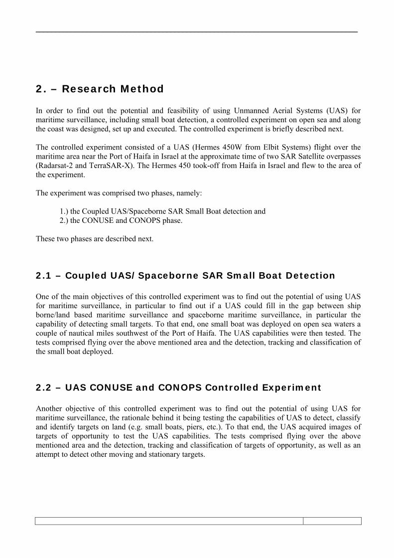
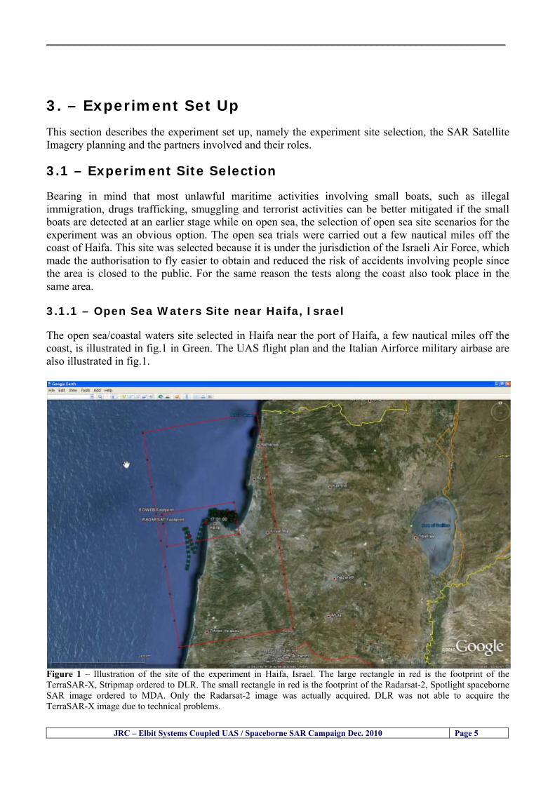
__________________________________________________________________________________
JRC ndash Elbit Systems Coupled UAS Spaceborne SAR Campaign Dec 2010 Page 5
3 ndash Experiment Set Up This section describes the experiment set up namely the experiment site selection the SAR Satellite Imagery planning and the partners involved and their roles
31 ndash Experiment Site Selection Bearing in mind that most unlawful maritime activities involving small boats such as illegal immigration drugs trafficking smuggling and terrorist activities can be better mitigated if the small boats are detected at an earlier stage while on open sea the selection of open sea site scenarios for the experiment was an obvious option The open sea trials were carried out a few nautical miles off the coast of Haifa This site was selected because it is under the jurisdiction of the Israeli Air Force which made the authorisation to fly easier to obtain and reduced the risk of accidents involving people since the area is closed to the public For the same reason the tests along the coast also took place in the same area
311 ndash Open Sea Waters Site near Haifa Israel The open seacoastal waters site selected in Haifa near the port of Haifa a few nautical miles off the coast is illustrated in fig1 in Green The UAS flight plan and the Italian Airforce military airbase are also illustrated in fig1
Figure 1 ndash Illustration of the site of the experiment in Haifa Israel The large rectangle in red is the footprint of the TerraSAR-X Stripmap ordered to DLR The small rectangle in red is the footprint of the Radarsat-2 Spotlight spaceborne SAR image ordered to MDA Only the Radarsat-2 image was actually acquired DLR was not able to acquire the TerraSAR-X image due to technical problems
__________________________________________________________________________________
JRC ndash Elbit Systems Coupled UAS Spaceborne SAR Campaign Dec 2010 Page 6
32 ndash SAR Satellite Imagery Planning The Synthetic Aperture Radar (SAR) satellite imagery available at the time the planning was done comprised a Radarsat2 (Spotlight) and a TerraSAR-X (Stripmap) Figure 2 illustrates the TerraSAR-X Stripmap SAR image footprint in red The image was ordered to DLR the German Aerospace Centre but unfortunately it was not possible to acquire it due to technical problems Figure 3 illustrates the footprint of the Radarsart-2 Spotlight SAR image in red
Figure 2 ndash The rectangle in red illustrates de footprint of the TerraSAR-X Stripmap image ordered to DLR Fortunately due to technical problems DLR was not able to acquire this spaceborne SAR image The approximate start date of acquisition was 2010-12-08T15380373
__________________________________________________________________________________
JRC ndash Elbit Systems Coupled UAS Spaceborne SAR Campaign Dec 2010 Page 7
Figure 3 ndash The rectangle in pink illustrates de footprint of the Radarsat-2 Spotlight SAR image ordered to MDA Fortunately due to technical problems DLR was not able to acquire this spaceborne SAR image The approximate start date of acquisition was 2010-12-08T15474000 UTC Table-1 illustrates the SAR satellite images and image modes used in the different days of the experiment
Table 1ndash TerraSAR-X Stripmap and Radarsat2- Spotlight High Resolution 08-Dec-2010 Satellite Evening Satellite Pass 1 TerraSAR-X Stripmap 2010-12-08T15380373 UTC 2 Radarsat-2 Spotlight 2010-12-08T15474000 UTC
__________________________________________________________________________________
JRC ndash Elbit Systems Coupled UAS Spaceborne SAR Campaign Dec 2010 Page 8
The Radarsat2 and TerraSAR-X image modes used in the present experiment will be briefly reviewed in the next paragraphs Radarsat2 - Spotlight Mode ndash The Spotlight Beams are intended for applications which require the best spatial resolution available from the RADARSAT-2 SAR system In this mode the radar operates with the highest sampling rate and so the ground swath coverage is limited to keep data rate within the recorder limits Unlike the other modes Spotlight images are also of fixed size in the along track direction The ser of Spotlight Beams cover any area within the incidence angle range from 20 to 49 degrees Each beam within the set images a swath width of at least 18 km Spotlight images can only be generated in a single polarization which can be either a linear co-polarization (HH or VV) or a linear cross-polarization (HV or VH)
Figure 4 ndash Radarsart2 image modes The Ultrafine and the Spotlight modes have been identified as the most suitable modes for this particular experiment Radarsat2 - Single Beam Mode ndash Single beam mode is a stripmap SAR mode In Single Beam operation the beam elevation and profile are maintained constant throughout the data collection period The following Single Beam modes are available Standard Wide Fine Multi-Look Fine Ultra-Fine Extended High (High Incidence) Extended Low (Low Incidence) Standard Quad Polarization and Fine Quad Polarization We selected Ultra-Fine because it is the best compromise between swath coverage and resolution
__________________________________________________________________________________
JRC ndash Elbit Systems Coupled UAS Spaceborne SAR Campaign Dec 2010 Page 9
Radarsat2 - Ultra-Fine ndash The Ultra-Fine Resolution Beams are intended for applications which require very high spatial resolution In this mode the radar operates with the highest sampling rate and so the ground swath coverage is limited to keep data rate within the incidence angle from 20 to 49 degrees Each beam within the set images a swath width of at least 20 km Ultra-Fine Resolution images can only be generated in a single cross-polarization which can be either a linear co-polarization (HH or VV) or a linear cross-polarization (HV or VH) The standard TerraSAR-X operational mode is the single receive antenna mode from which the following imaging modes can be retrieved High Resolution Spotlight and Spotlight StripMap and ScanSAR The single receive antenna mode uses a chirp bandwidth of up to 300 MHz
Figure 5 ndash Radarsart2 image modes The Ultrafine and the Spotlight modes have been identified as the most suitable modes for this particular experiment The SpotLight (SL) imaging modes use phased array beam steering in azimuth direction to increase the illumination time ie the size of the synthetic aperture This leads to a restriction in the image scene size Thus the scene size is technically restricted to a defined size 10 km x 10 km for the SpotLight mode and 10 km x 5 km (width x length) in the HighResolution SpotLight (HS) mode This sophisticated imaging mode makes it possible to acquire data with up to 1 m resolution in the HighResolution SpotLight mode (acquired with a bandwidth of 300 MHz) and 2 m in the standard SpotLight mode StripMap (SM) is the basic SAR imaging mode as known eg from ERS-1 and other radar satellites The ground swath is illuminated with continuous sequence of pulses while the antenna beam is fixed in elevation and azimuth This results in an image strip with a continuous image quality (in flight direction) StripMap dual polarisation data have a slightly lower spatial resolution and smaller swath than the single polarisation data In StripMap mode a spatial resolution of up to 3 m can be achieved The standard scene size is 30 km x 50 m (width x length) in order to obtain manageable image files however acquisition length is extendable up to 1650 km
__________________________________________________________________________________
JRC ndash Elbit Systems Coupled UAS Spaceborne SAR Campaign Dec 2010 Page 10
33 ndash Partners Involved and their Roles The partners involved in this experiment comprised the European Commission (EC) ndash Joint Research Centre (JRC) and Elbit Systems from Haifa Israel The role of each partner is briefly described next 331 - European Commission (EC) ndash Joint Research Centre (JRC) ndash The main role of the EC-JRC was the planning set up execution and the analysis of the data together with Elbit Systems This comprised
a) the definition of the objectives b) the research methods used c) the ground truth data collection d) the analysis of the data and the conclusions of the experiment
332 ndash Elbit Systems ndash The main role of Elbit Systems comprised
a) the deployment and operation of the boat used as target b) the deployment and operation of the UAS Hermes 450 c) the contacts with the Israeli authorities namely the Israeli Air Force and Civil Aviation
Authority d) the collection of ground truth data e) The analysis of the data and conclusions of the experiment
__________________________________________________________________________________
JRC ndash Elbit Systems Coupled UAS Spaceborne SAR Campaign Dec 2010 Page 11
4 ndash Experiment Execution
41 ndash Modus Operandi The modus operandi of the trial was as follows 1- JRC supplied Elbit Systems with the footprint (frame) of the spaceborne SAR images to be acquired (TerraSAR-X-Stripmap and Radarsat-2 Spotlight) as well as the time of the SAR satellite passes 2- The boat was deployed about 2 nautical miles Southwest of the Port of Haifa The boat was about 12-meter long The boat had a crew of 3 people plus one JRC staff 3- The boat left from the port of Haifa and travelled a couple of nautical miles to reach the test site Once the test site was reached the boat was stationary at the time of the satellite SAR overpass After the satellite overpasses the boat was steered at different speeds to test the tracking capabilities of the UAV
42 ndash Ground Truth Data Collection The ground truth data collected comprised a) the sea state b) Data from the UAS sensors b) the weather conditions and wind speed e) Photos and movies of the boats involved in the experiment
43 ndash Means Involved in the Experiment The means involved in the experiment comprised two satellite SAR images namely a TerraSAR-X-Stripmap and a Radarsat-2 Spotlight and one 12-meter long boat 431 ndash Boat Deployed During the Experiment Figures 6 illustrate the boat deployed as target during the experiment
__________________________________________________________________________________
JRC ndash Elbit Systems Coupled UAS Spaceborne SAR Campaign Dec 2010 Page 12
Figure 6 ndash The 12-meter boat deployed during the experiment at the Port of Haifa Israel 432 ndash Hermes 450 ndash System Overview The Hermesreg UAV system is a mature and operationally proven system with accumulated experience with the Israel Defense Forces operations and with other users worldwide It features a fully redundant architecture leading to a high level of safety and reliability a high level of autonomy modern high performance state-of-the-art payloads and a small logistic footprint Figure 7 shows the main elements of the Hermes UAV System 433 ndash The Air Vehicle Hermesreg 450W is a modern UAV design featuring highly efficient aerodynamics composite structure and a high level of system redundancy and autonomy Its compact size and high maximumempty weight ratio enable very high mission effectiveness delivering potent payloads high endurance and a modest logistic footprint The Hermesreg 450 is in production and has accumulated over 150000 flight hours with the Israeli Air Force and other users around the globe The Hermesreg 450W uses the higher power delivered by the AR802W engine to achieve higher gross weight with the same platform greatly increasing payload and fuel carrying capability a shorter takeoff run and expanded flight envelope
__________________________________________________________________________________
JRC ndash Elbit Systems Coupled UAS Spaceborne SAR Campaign Dec 2010 Page 13
The AR802W engine is a derivative of the AR802 rotary engine with widened rotor and housing The result is a 30 gain in power to nearly 70HP Coupled to an Electronic Fuel Injection system the engine is highly efficient and has improved maintenance figures Following is a summary of the physical characteristics of the Hermes 450W air vehicle is given in Table 2
Table 2 ndash Summary of Hermes 450 main characteristics Physical Characteristics
bull Length 61 m bull Wingspan 105 m bull Fuselage diameter 0508 mm bull Max takeoff weight 550 kg bull Max internal fuel weight (including oil) 115 kg bull Max payload weight 150 kg
Figure 7 ndash Elements of the Hermes UAV System
434 ndash Ground Control Station (GCS) The GCS is a transportable system designed to perform and support all Hermesreg UAV family ground Based activities operational activities These activities include mission planning pre-flight check takeoff and landing UAV flight control mission control payloads and systems control as well as post-mission debriefing An embedded or appended training capability is optional Remote communication of video and telemetry to a C4I center via SATCOM or WAN infrastructure is optional The GCS provides a user friendly comfortable effective and protected environment for carrying out UAV missions
__________________________________________________________________________________
JRC ndash Elbit Systems Coupled UAS Spaceborne SAR Campaign Dec 2010 Page 14
The GCS is housed in a shelter with operator consoles of advanced human engineering design that provide an ergonomic operational environment The shelter is based on the NATO ACE III shelter with a side door As Israelrsquos leading C4I provider Elbit Systems has incorporated Hermesreg GCS advanced C4I capabilities including comprehensive mission planning tactical database management and tactical coordination with supported forces and command elements The Hermesreg GCS is uniquely capable of performing two UAV missions concurrently with two UAVs each of which is controlled via a separate Ground Datalink Terminal (GDT) The Hermesreg GCS requires minimal operating personnel ie mission commander and mission operator
Figure 8 ndash The UAS Hermes 450 Ground Control Station (GCS)
435 ndash The EO Payload The CoMPASS Compact Multi Purpose Advanced Stabilized System is a day and night surveillance system that includes a 3rd generation 3-5 μm zoom FLIR camera a color zoom TV CCD camera and automatic tracking capabilities The CoMPASS enables the following
bull Day and night stabilized LOS observation with capabilities of target detection recognition and identification in various weather conditions
bull Automatic and manual tracking of targets bull Slaving CoMPASS Line of Sight (LOS) to external systems bull LOS information bull Target Laser designationampRanging or only Target Laser Ranging bull Laser Target Marker
__________________________________________________________________________________
JRC ndash Elbit Systems Coupled UAS Spaceborne SAR Campaign Dec 2010 Page 15
CoMPASS the EOIR system for UAV applications is the most advanced payload version of the CoMPASS family featuring reduced weight high degree of modularity and flexibility space-saving packaging and advanced operational and video processing features The CoMPASS based STA Stabilized Turret Assembly is a single LRU housing
bull 3rd generation 3-5 μm FLIR zoom Camera bull Color Zoom TV CCD Camera bull Laser Target Designator bull Laser Target Marker bull Electronic Boards
Figure 9 ndash CoMPASS Stabilized Turret Assembly (STA)
__________________________________________________________________________________
JRC ndash Elbit Systems Coupled UAS Spaceborne SAR Campaign Dec 2010 Page 16
5 ndash Preliminary Data Analysis
51 ndash SAR Satellite Imagery Processing The high resolution spaceborne SAR image was analysed visually because the resolution is good enough to allow visual analysis and the site is too close to the coast which makes automatic processing more difficult and prone to error due to artefacts caused by land targets The Hermes 450 images were also analysed visually
52 ndash Ground Truth Data This section briefly describes the Ground Truth data namely the GPS positions of the boat deployed as target during the experiment a photo of the boat as well as other relevant ground truth data collected
521 ndash GPS coordinates of the boat deployed Table 5 gives the GPS coordinates of the boat deployed during the experiment at the time of the Radarsat-2 satellite overpass Table 3 ndash Ground Truth data collected at the time of the satellite pass (154740 UTC=174740 LT) on 8 December 2010
Date 8 Dec2010 Time 154740 UTC=174740 LT Pass Ascending
SatelliteMode Radarsat-2 Spotlight Polarisation HH
Boats Type Size Latitude Longitude
Elbits 12-meter
Boat
32˚ 51830 N 32deg514980N 32863833deg N
34˚ 57961 E 34deg575766E 34966017deg E
__________________________________________________________________________________
JRC ndash Elbit Systems Coupled UAS Spaceborne SAR Campaign Dec 2010 Page 17
521 ndash HERMES 450 Ground Truth Data Table 4 shows the 12-meter Elbitacutes Boat as detected by the IR sensor of the Hermes 450 Table 4 ndash Hermes 450 Ground Truth Data Date 8 Dec2010 Time 154740 UTC=174740 LT
Platform Hermes 450
UAV Type Size Latitude Longitude
UAV Hermes
450
174730h 3284489947 N
174800h
3285089687 N
174730h 3498564048 E
174800h
3499338667 E
Elbits 12-meter
Boat UAV
Image
32˚ 51830 N 32deg514980N 32863833deg N
34˚ 57961 E 34deg575766E 34966017deg E
53 ndash Weather Conditions and Sea State The weather conditions in Haifa are summarized in Table 5 bellow
Table 5 ndash Wind speed wind direction and Temperature Time (IST) Temp Dew
Point Humidity Pressure Visibility Wind Dir
Wind Speed
Gust Speed Precip Events Conditions
550 PM 210 degC 130 degC 60 1017 hPa - North 111 kmh
31 ms - NA Clear
__________________________________________________________________________________
JRC ndash Elbit Systems Coupled UAS Spaceborne SAR Campaign Dec 2010 Page 18
Figure 10 gives the weather data (Temperature Barometric Pressure Wind Speed and Wind Direction) for Haifa Israel on 8 Dec 2010
Figure 10 ndash Weather data (Temperature Barometric Pressure Wind Speed and Wind Direction) for Haifa Israel on 8 Dec 2010
__________________________________________________________________________________
JRC ndash Elbit Systems Coupled UAS Spaceborne SAR Campaign Dec 2010 Page 19
54 ndash Verification of the Results This section briefly describes the verification of the targets detected in the spaceborne SAR image and in the Hermes 450 UAV using the ground truth data collected during the experiment
541 ndash Overview of the UAV Trajectory and the SAR Imagery Footprint Figure 11 gives an overview of the UAV trajectory the footprint of the SAR imagery and the area of the experiment near the port of Haifa The UAV trajectory is depicted in blue The large red rectangle is the footprint of the TerraSAR-X Stripmap The smaller red rectangle is the footprint of the Radarsat-2 Spotlight image
Figure 11 ndash Google Earth UAV trajectory during the experiment and footprinst of the SAR imagery ordered for the experiment Figure 12 is a zoom in of the previous image which allows a more detailed view of the UAV trajectory and of the port of Haifa Figure 13 is a zoom in of figure 12 It shows in more detail the UAV trajectory during the entire experiment and the port of Haifa in Israel
__________________________________________________________________________________
Figure 12 ndash Zoom in of the previous figure showing a more detailed view of the UAV trajectory and of the port of Haifa in Israel
Figure 13 ndash Zoom in of the previous figure showing a even more detailed view of the UAV trajectory and of the port of Haifa in Israel
JRC ndash Elbit Systems Coupled UAS Spaceborne SAR Campaign Dec 2010 Page 20
__________________________________________________________________________________
JRC ndash Elbit Systems Coupled UAS Spaceborne SAR Campaign Dec 2010 Page 21
542 ndash Targets Detected in the Radarsat-2 Spotlight Image Figure 14 illustrates the position of the Elbitrsquos boat used as target in the experiment at the approximate time of the SAR Satellite pass by 1547 UTC (1747 LT) The small photo of the boat shows the approximate position of the boat The two small planes show the positions of the UAV immediately before and after the SAR Satellite pass
Figure 14 ndash Google Earth positions of the elbitrsquos boat and the UAV (Hermes450) at the approximate time of the SAR Satellite overpass by 174740 UTC Figure 15 shows the corresponding SAR image (Radarsat-2 Spotlight) acquired during the experiment Pins 1 and 2 represent the positions of the UAV before and after the SAR satellite overpass Pin 3 illustrates the position of the Elbitacutes boat deployed at the time of the satellite overpass At this scale the SAR signature of the boat is not distinguishable from the sea clutter background However zooming in the SAR image the SAR signature can clearly be seen as illustrated in figure 12 The SAR image in figure 12 also shows several SAR signatures of large ships in the area at the time of the satellite overpass
__________________________________________________________________________________
JRC ndash Elbit Systems Coupled UAS Spaceborne SAR Campaign Dec 2010 Page 22
Elbit`s Boat
Figure 15 ndash On the background the SAR image with the two UAV positions before and after the satellite overpass (Pin1 and Pin2) and the Elbitacutes Boat position (Pin3) The small window over the SAR image shows a zoom in of the SAR image where the SAR signature of the Elbitacutes Boat can clearly be seen The top right are of the SAR image also shows SAR signatures of several large ships in the area at the time of the SAR satellite overpass Figure 16 shows the corresponding SAR image (Radarsat-2 Spotlight) acquired during the experiment and the UAV IR images of some of the targets Pins 1 and 2 represent the positions of the UAV before and after the SAR satellite overpass Pin 3 illustrates the position of the Elbitacutes boat deployed at the time of the satellite overpass At this scale the SAR signature of the boat is not distinguishable from the sea clutter background However zooming in the SAR image the SAR signature can clearly be seen as illustrated in figure 13 On the top left the UAV IR image of the Elbitrsquos Boat The SAR image in figure 13 also shows several SAR signatures of large ships in the area at the time of the satellite overpass On the centre left the UAV IR image of a large ship On the centre right the UAV IR image of a large ship On the bottom right the UAV IR image of a large ship All the UAV images were acquired at night in complete darkness from altitudes in the order of 5500 meters Nonetheless the quality and detail of the UAV images allows classification of the targets and in some cases the identification As it can be seen the potential of UAV for maritime surveillance is very promising During the experiment the UAV detected all the boats and ships in the area and tracked some of the boatsships to test the tracking capability The capability of detection and tracking targets is a critical capability for maritime surveillance
__________________________________________________________________________________
JRC ndash Elbit Systems Coupled UAS Spaceborne SAR Campaign Dec 2010 Page 23
Elbitacutes Boat
Elbit`s Boat
Figure 16 ndash Zoom-in of figure 15 with the UAV images of some targets On the top left the UAV IR image of the Elbitrsquos Boat On the centre left the UAV IR image of a large ship On the centre right the UAV IR image of a large ship On the bottom right the UAV IR image of a large ship Figure 17 shows a comparison of the SAR and UAV images with an optical photo taken in Haifa Israel a couple of hours before the SAR satellites overpass Most of the large ships were detected in the SAR image and some of these ships can be identified in the optical photo Some of the ships in the photo left the area before the SAR satellites overpass
__________________________________________________________________________________
JRC ndash Elbit Systems Coupled UAS Spaceborne SAR Campaign Dec 2010 Page 24
Figure 17 ndash Photo taken in Haifa Israel a couple of hours before the SAR satellites overpass This phot shows the large ships moored in the area Most of these large ships were detected in the Radarsat-2 image As expected their positions and orientations were slightly different at the time of the satellite overpass
Elbitacutes Boat
Elbit`s Boat
__________________________________________________________________________________
JRC ndash Elbit Systems Coupled UAS Spaceborne SAR Campaign Dec 2010 Page 25
Figure 18 ndash Photo taken in Haifa Israel a couple of hours before the SAR satellites overpass This phot shows the large ships moored in the area Most of these large ships were detected in the Radarsat-2 image As expected their positions and orientations were slightly different at the time of the satellite overpass Figure 18 illustrates the SAR image and the corresponding google earth image of a small pier in the port of Haifa In the SAR image due to several artefacts it is not possible to detect the 7 small boats moored to the small pier The UAR IR image of the same area clearly shows the 7 small boats with impressive detail taking into account that the image was acquired from an altitude of about 5500 meters A zoom in of the same UAV IR image is shown in figure 19 As it can be seen although the image was acquired from an altitude of about 5500 meters the 7 small boats can be clearly seen with enough detail to allow classification of the type of boat A UAV flight at lower altitude would probably giver a lot more detail and eventually allow the identification of the small boats
__________________________________________________________________________________
JRC ndash Elbit Systems Coupled UAS Spaceborne SAR Campaign Dec 2010 Page 26
Figure 19 ndash UAV IR image of a small pier in the port of Haifa Israel where 7 small boats can be seen with enough detail to allow classification This image was acquired from an altitude of about 5500 meters in the dark
__________________________________________________________________________________
55 ndash Quantitative Analysis of the Spaceborne SAR Image In order to allow a quantitative analysis of the data the spaceborne SAR image was calibrated using ESArsquos NEST software package version 4B The input was the SAR image acquired and the output was the Radiometric Calibration (Sigma Naught (σdeg)) expressed in terms of intensity and in decibel (dB) the Radar Brightness (βdeg) and the Radiometric Normalisation (gamma naught (γdeg))
551 ndash Radarsat-2-Spotlight 08Dec2010 (154740 UTC) Haifa Israel Figure 20 illustrates the Intensity band of a subset of the Radarsat-2Spotlgiht image (08Dec2010)
Figure 20 ndash Radarsat-2 Spotlgiht image (08Dec2010) ndash Sigma Naught (Intensity) band
JRC ndash Elbit Systems Coupled UAS Spaceborne SAR Campaign Dec 2010 Page 27
__________________________________________________________________________________
Figure 21 illustrates the Sigma Naught Coefficient of the Radarsat-2 Spotlgiht image (08Dec2010) expressed in terms of intensity and decibel (dB)
Figure 21 ndash Radarsat-2 Spotlgiht image (08Dec2010) - On the left the Sigma Naught (σdeg) (intensity) and on the right the Sigma Naught (σdeg) (dB)
ormalisation amma Naught (γdeg)) of the Radarsat-2 Spotlgiht image (08Dec2010) expressed in dB
-2 Spotlgiht image (08Dec2010) - On the left the Beta Naught (βdeg) and on the right the Gamma Naught (γdeg) (dB)
Figure 22 illustrates the Radar Brightness (Beta Naught (βdeg)) and the radiometric n(G
Figure 22 ndash Radarsat
JRC ndash Elbit Systems Coupled UAS Spaceborne SAR Campaign Dec 2010 Page 28
__________________________________________________________________________________ Figure 23 shows the Sigma Naught (σdeg) in dB after some colour manipulation and the histogram of the Sigma Naught (σdeg) image
Figure 23 ndash Radarsat-2 Spotlgiht image (08Dec2010) - On the top left the Sigma Naught (σdeg) after colour manipulation to enhance the targets and on the top right the corresponding histogram On the bottom we can see the histogram of the image
Table 6 gives the statistics of the Sigma Naught (σdeg) Radarsat-2 Spotlgiht image (08Dec2010) The Sigma Naught (σdeg) range from -72897 dB up to 23465 dB The Mean value is -16855 dB the Median is -16594 dB and the standard deviation is 7077 dB
JRC ndash Elbit Systems Coupled UAS Spaceborne SAR Campaign Dec 2010 Page 29
__________________________________________________________________________________
JRC ndash Elbit Systems Coupled UAS Spaceborne SAR Campaign Dec 2010 Page 30
Table 6 ndash Statistics of the Radarsat-2 Spotlgiht image (08Dec2010) (154740 UTC)
Statistics Values Unit Only ROI-Mask pixels considered Number of pixels total Number of considered pixels Ratio of considered pixels
No 322394283 322394283
1000
Minimum Maximum
-728974609375 234655818939209
intensity_db intensity_db
Mean Median Std-Dev Coefficient of Variation
-16855686580177853 -1659462338617847 707796800831575
07888765273432338
intensity_db intensity_db intensity_db intensity_db
Checking the radar backscattering coefficient of some targets (small boat and some large ships) detected in the Radarsat-2 Spotlight image we get values ranging from -0379 dB up to 23455 dB The analysis of the Sigma Naught values (σdeg) of the targets and the area around the targets shows a significant contrast
56 ndash Summary of the Preliminary Analysis of the Spaceborne SAR Image This experiment involved two spaceborne SAR images namely a TerraSAR-X Stripmap and one Radarsat-2 Spotlight The TerraSAR-X image was not delivered by DLR due to technical problems The Elbitrsquos boat deployed during the experiment was detected in the Radarsat-2 Spotlight image Several other targets including a set of large ships were also detected Table 7 summarises the characteristics of the SAR image acquired and the targets detected
Table 7 ndash List of SAR Satellite Images acquired during the experiment and detected boats ISRAEL (HAIFA)
Date Time Place Satellite Mode Ground Truth Data Detected Boats
08Dec2010 (PM) Haifa - Israel Radarsat-2 Spotlight GPSPhotosMovies 1 small boat deployed + 9 large ships
Table 8 gives the minimum and maximum Sigma Naught (σdeg) of the targets detected in each SAR image
Table 8 ndash Minimum and maximum Sigma Naught (σdeg) of the targets detected in each SAR image
Date Time UTC (LT)Pass Satellite Image Mode Polarisation Sigma Naught (σdeg) Min Max
29Oct2010528UTC(728AM LT) DES Radarsat-2 Spotlight HH --0379 dB 23455 dB The SAR signatures of the boats deployed were very weak Some possible reasons to explain such weak signatures are the sea state the wind speed the incidence angle and the type and materials Another possible reason is the processing at DLR
__________________________________________________________________________________
JRC ndash Elbit Systems Coupled UAS Spaceborne SAR Campaign Dec 2010 Page 31
6 ndash Preliminary Conclusions The analysis of the results of this coupled UASSpaceborne SAR experiment shows a promising potential for the use of UAS for maritime surveillance UAS can be integrated into the airborne building block of maritime surveillance systems to complement the existing assets increase system performance and improve the overall maritime domain awareness The main perceived maritime security and safety threats comprise piracy terrorist and military threats weapons proliferationsmuggling drugs trafficking illegal immigration unlawful use of containers attacks to critical infrastructures and illegal fishing The main maritime security and safety gaps include a lack of technologies with the capability of detecting small targets (eg small boats) a lack of wide area and persistent maritime surveillance a lack of coordination and information sharing limited interoperability a lack of containers security a lack of persistent surveillance of critical infrastructures and early warning systems Unmanned Aircraft Systems (UAS) are an emerging technology with strong potential to mitigate the above mentioned threats by filing in the main maritime security and safety gaps listed earlier For instance the wide range of potential applications of UAS to maritime surveillance includes but is not limited to
bull detection classification and identification of small boats bull persistent maritime surveillance bull use as communications relays bull persistent surveillance of critical infrastructures bull early warning systems bull COMINT and ELINT collection etc
Table 11 illustrates the mapping of maritime securitysafety threats vs gaps and summarises the main potential applications of UAS to maritime surveillance The above mentioned potential applications of UAS to the Maritime Domain will be addressed in turn in more detail next bull Detection classification and identification of small boats ndash The capability of detecting classifying and identifying small targets (eg small boats) is among the key technologies required to improve maritime domain awareness This capability is critical to mitigate piracy illegal immigration drugs trafficking weapons smuggling illegal fishing terrorism and critical infrastructure Unmanned Aircraft Systems (UAS) provide this capability more efficiently and at a lower cost than any other existing technology bull Persistent maritime surveillance ndash With the continuous improvements of UAS technologies such as platforms sensors collision avoidance systems command and control systems telecommunications etc UAS are increasing their autonomy endurance and flexibility These characteristics are very important for persistent maritime surveillance UAS can be launched from land ships aircraft and technologies to launch UAS from submarines are currently under development UAS have distinct advantages over other existing technologies for persistent maritime surveillance in terms of autonomyendurance (the Global Surveyor has an autonomy of 1 week) cost (eg as the autonomy of UAS increases the number of staff required to operate UAS decreases) risk (eg if the UAS crashes the crew is not at risk) flexibility (eg they can be launched from a ship reducing the time to reach potential threats) etc
__________________________________________________________________________________
JRC ndash Elbit Systems Coupled UAS Spaceborne SAR Campaign Dec 2010 Page 32
bull Communications relays ndash UAS are being used as communication relays mainly in military context but have the potential to play a similar role in Civil context in several situations such as to replace satellite communications or as a redundant system over any location on Earth The main advantages of using UAS as communication relays is that airborne communication relays mitigate kinetic and noise jamming threats to satellite communications uplinks by providing an alternative set of links either directly to surface-based terminals or to satellites beyond the range of threats They are less susceptible to noise jamming threats than satellites because an adversary has to detect geolocate and track the airborne asset and operate within line of sight of the receive antenna main beam bull Persistent surveillance of critical infrastructures ndash The security of critical infrastructures such as nuclear power plants refineries ports etc requires persistent surveillance UAS can play an important role in providing persistent surveillance over critical infrastructures and over a wide area around the critical infrastructure Some advantages of UAS over other existing technologies such as ground-based assets (eg video cameras alarm systems manned aircraft etc) comprise the security of the UAS (eg hardly can be damaged or switched off as any ground-based asset) the area covered by a UAS (eg it is larger than the area covered by any ground-based asset) the cost (eg UAS is cheaper than manned aircraft with similar capability) etc bull Early warning systems ndash UAS have the potential to be used as part of an integrated system of systems for early warning A UAS can provide information about a given area at a fraction of the cost of alternative means Formation flying of UAS can cover a wide maritime area It is reasonable to assume that in a foreseeable future with the advent of UAS with increased autonomy the operations cost of UAS will likely decrease making them increasingly more attractive bull COMINT and ELINT collection ndash SIGNal INTelligence (SIGNINT) can be divided into two categories namely COMINT and ELINT COMINT stands for Communication Intelligence and ELINT for Electronic Intelligence Collection of COMINT is passive Exploitation of COMINT requires a human operator which implies COMINT UAS are suitable for COMINT and ELINT collection in different scenarios The relatively reduced amount of data collected and analysed during this experiment and the lessons learned do not allow drawing final conclusions about the feasibility of using Unmanned Aerial Systems (UAS) for maritime surveillance However this experiment allowed hands-on experience with UAS technologies and significantly improved the awareness for its applications to maritime surveillance and related issues involved including its potential the feasibility as well as the limiting and enabling factors These different aspects will now be analysed in turn in the next sections Table 11 illustrates the mapping of the main maritime security threats and gaps as well as the main priorities in terms of the different technologies involved in maritime surveillance For each maritime threat the technologies required to fill in each gap is indicated and its priority is expressed in a range of numbers (1 to 3 1 = Maximum Priority 2 = Medium Priority 3 = Low Priority) and colours (Red = Maximum Priority Orange = Medium Priority Green = Low Priority) The main technologies involved in maritime surveillance are listed on the bottom of figure 4 and are reproduced here for convenience of the reader 1- Reporting Systems 2- Sensors 3- Platforms 4- Communications 5- Data Fusion amp Sharing 6- Intelligence and 7- Databases For example the mitigation of the main threat Piracy requires filling in several maritime security gaps (eg lack of persistent surveillance lack of wide-are maritime surveillance lack of small boat detection lack of Early Warning Systems and lack of Information Sharing with maximum priority (1- Red) and among the required technologies listed are UAS LTAAV GEO-HR etc Concerning the remaining two gaps (Limited Interoperability and Containers Security) they are less relevant to mitigate Piracy hence the priority for Limited Interoperability is 2-Orange and for Containers Security is 3- Green
__________________________________________________________________________________ Table 9 ndash The Main Maritime Security and Safety Threats vs Gaps and the technologies that can be used to mitigate them
Maritime Security Main Threats GapsGapsrarr
darrThreats
Lack o f Risk As sessmentCapab ility
La ck of Persiste nt
Surveilla nce
La ck of Wid e-Area su rve illanc e
La ck of Small Boat De tecti on
Lack o f Earl y Warn ing Sys tems
L ack of In forma tion
Sh arin g
L imi ted In terop era bility
Lac k of Co ntai ners
Se cur ity
bull PiracyUAS LTAVG EO-
HR + UAS LT AVGEO-
HR + SAR GEO-HR
+ UAS USV LTAV
+ UAS LTAV
+ Coord in ationamp Sharing +
Inter opera bilityOptimisation +
1 2 3 5 6 7 1 2 3 5 6 7 1 2 3 5 6 1 2 3 123456 4567 1234567 1234567
bull Terro rismUAS LTAVG EO-
HR + UAS L TAV GEO-HR +
SAR AISGEO-HR +
UAS USV LTAV+
Intelligence+
Inte lligen ce+
Inter opera bilityOptimisation +
Intelligence+
1 2 3 5 6 7 1 2 3 5 6 1 2 3 5 6 1 2 3 123456 4567 1234567 1234567
bull Wea pon s ofM ass Dest ru ctio n Smugg ling
UAS LTAVG EO-HR +
UAS LT AVGEO-HR +
SAR AIS+
UAS USV LTAV+
Intelligence+
Inte lligen ce+
Intelligence+
Intelligence+
1 2 3 5 6 7 1 2 3 5 6 1 2 3 5 6 1 2 3 123456 4567 1234567 1234567
bull Drug sTraffic king
UAS LTAVG EO-HR +
UAS LT AVGEO-HR +
SAR AIS+
UAS USV LTAV+
Intelligence+
Inte lligen ce+
Intelligence+
Intelligence+
1 2 3 5 6 7 1 2 3 5 6 1 2 3 5 6 1 2 3 123456 4567 1234567 1234567
bull Illega lImmigratio n
UAS LTAVG EO-HR +
UAS LT AVGEO-HR +
SAR AIS+
UAS USV LTAV+
Intelligence+
Inte lligen ce+
Intelligence+
Intelligence+
1 2 3 5 6 7 1 2 3 5 6 1 2 3 5 6 1 2 3 123456 4567 1234567 1234567
bull Critic alI nfrastruc tureSecu rit y
UAS LTAVG EO-HR +
UAS LT AVGEO-HR +
SAR AIS+
UAS USV LTAV+ + Inte lligen ce
+ Intelligence
+ Intelligence
+
1 2 3 5 6 7 1 2 3 6 1 2 3 5 6 1 2 3 123456 4567 1234567 1234567
bull Illega lFish ing
UAS LTAVG EO-HR +
AI S+SAR UASLTAV +
SAR AIS GEO-HR+
UAS USV LTAV+
Intelligence+
Inte lligen ce+
Intelligence+
1 2 3 5 6 7 1 2 3 5 7 1 2 3 5 6 1 2 3 123456 4567 1234567
bull Un lawf ul Use of Co nta iners
(Secur ity)
UAS LTAVG EO-HR +
GPS Tr acking+
Intelligence+
Inte lligen ce+
GPS Int rusion Det ection Se al
1 2 3 5 6 7 4 6 7 1 2 3 5 6 1 2 3 123456 4567 1234567 1234567
(-) Priority (+) Not Rel evant
SURVEILLANCETECHNOLOGIES
1- Reporti ng Systems
2 -Sensors 3 -P latforms 4 - Communications 5- Data Fusionamp Sharing
6 -I ntelli gence 7 -Databases
JRC ndash Elbit Systems Coupled UAS Spaceborne SAR Campaign Dec 2010 Page 33
__________________________________________________________________________________
JRC ndash Elbit Systems Coupled UAS Spaceborne SAR Campaign Dec 2010 Page 34
61 ndash Hands-on experience with UAS technologies and its applications to maritime surveillance This coupled UASSpaceborne SAR campaign was a unique opportunity to acquire further handsndashon experience with UAS technologies and learn about the main issues related to its applications to maritime surveillance From the planning phase up to the execution of the UAS flight and landing there are several factors that need to be carefully analysed and taken into account A summary of the main issues identified in this experiment is given next 1- Selection of the Experiment Area Authorisation to Fly ndash For the time being UAS can only be flown in restricted areas usually under control of national authorities often the military This is due to the risks that a UAS can pose to human life and property In the present case an area under the authority of the Israeli Civil Aviation Authority was selected The authorisation to fly was not easy to obtain because the selected area is under the authority of the Civil Aviation Authority Figure 24 indicates the area of the experiment in Haifa Israel 2- UAS Communications Issues ndash The Hermes 450 was flown in Line-of-Sight (LOS) since it was close to the coast For BLOS (Beyond Line-of-Sight) operation satellite communications are required 3- Synthetic Aperture Radar (SAR) ndash The specific model Hermes 450W used in the experiment had no SAR sensor installed However a SAR sensor can be installed A SAR sensor is important for maritime surveillance since it allows 247 operations regardless of the weather conditions 4- Automatic Identification System (AIS) Receiver ndash The Hermes 450 used in this experiment was not equipped with an AIS receiver For maritime surveillance operations an AIS receiver is a very important tool since it allows the automatic identification of most ships allowing the UAS to concentrate on non-identified ships
__________________________________________________________________________________
Figure 24 ndash The area of the experiment is indicated by the GPS Trajectory of the UAV
62 ndash Potential of UAS for Maritime Surveillance UAS technologies are relatively recent and involve a wide range of fields spanning from aeronautics and sensors technologies to satellite communications and other engineering disciplines Innovations in each of the fields involved are emerging by the day UAS still have a long way to go before they become mature and their use fully operational For the time being UAS are mainly used for military applications However a large number of non-military UAS applications have been identified by stakeholders and there are several studies and demonstration flights foreseen for the near future Maritime surveillance is one of the most challenging and promising fields of application of UAS The challenges are due to the very demanding conditions under which the UAS must operate over sea and the requirements for safe operation
JRC ndash Elbit Systems Coupled UAS Spaceborne SAR Campaign Dec 2010 Page 35
__________________________________________________________________________________
JRC ndash Elbit Systems Coupled UAS Spaceborne SAR Campaign Dec 2010 Page 36
The present UAS experiment has unveiled some of the potential of UAS for maritime surveillance The UAS tests performed during this experiment include
1 ndash Detection of a Small rubber Boat and a Fishing Ship 2 ndash Tracking of a Small Boat and a Fishing Ship 3 ndash Classification of a Small Boat and a Fishing Ship 4 ndash Identification of a Small Boat and a Fishing Ship 5 ndash Detection and Tracking of People on the Beach
Despite the operational requirement that prevented the UAS from flying bellow 3km the experiment has confirmed the capability of UAS for small boat detection tracking and classification as well as the capability for people detection and tracking Concerning the identification of the targets the characteristics of the images acquired during this mission suggest that flying at lower altitudes the UAS images would allow the identification of the targets The UAS images can be seen from Figure 15 to 20
621 ndash Advantages of UAS for maritime Surveillance Some of the advantages of using UAS for maritime surveillance have been described in the literature and are summarized bellow
1- One potential benefit of UAS is that they could fill in a gap in current maritime surveillance by improving coverage
2- The range of UAS is a significant asset when compared to border agents on patrol or stationary surveillance equipment
3- Eletro-Optical InfraRed (EOIR) sensors (cameras) can identify small size objects from very high altitudes (high resolution)
4- UAS can provide precise and near-real-time imagery to a ground control operator who would then disseminate that information so that informed decisions regarding the deployment of border patrol agents can be made quickly
5- Long endurance UAS used along the border can fly for more than 30 hours up to several days without having to refuel compared with manned helicopterrsquos average flight time of just over 2 hours
6- The ability of UAS to loiter for prolonged periods of time has important operational advantages over manned aircraft
7- The longer flight times of UAS means that sustained coverage over a previously exposed area may improve maritime security
8- The range of UAVs is a significant asset when compared to border agents on patrol or stationary surveillance equipment Nevertheless the extended range and endurance of UAVs may lessen the burdens on human resources at the borders
9- UAS accidents do not risk the lives of pilots as do the helicopters and aircraft currently used by Coast Guards for border patrolling
__________________________________________________________________________________
JRC ndash Elbit Systems Coupled UAS Spaceborne SAR Campaign Dec 2010 Page 37
622 ndash Possible Drawbacks of using UAS for maritime Surveillance UAS also have disadvantages some of them are briefly described next
1- There have been concerns regarding the high accident rate of UAS which can be multiple times higher than that of manned aircraft Because UAS technology is still evolving there is less redundancy built into the operating system of UAS than of manned aircraft and until redundant systems are perfected mishap rates are expected to remain high
2- If control systems fail in a manned aircraft a well-trained pilot is better positioned to find the source of the problem because of hisher physical proximity If a UAS encountered a similar system failure or if a UAS landing was attempted during difficult weather conditions the ground control pilot would be at a disadvantage because he or she is removed from the event Unlike a manned pilot the remote pilot would not be able to assess important sensory information such as wind speed
3- Inclement weather conditions can also impinge on a UAS surveillance capability especially UAS equipped with only an EO camera and Forward Looking Infrared Radar (FLIR) because cloudy conditions and high humidity climates can distort the imagery produced by EO and FLIR equipment The effects of extreme climatic or atmospheric conditions on sensors reportedly can be mitigated with the outfit of one synthetic aperture radar (SAR) system and a moving target indicator (MTI) radar However adding SAR and MTI to a UAS platform would increase the costs associated with using UAS
4- Depending on the type of UAS the costs of operating a UAS can be higher than the costs of operating a manned aircraft This is because some types of UAS require a significant amount of logistical support and specialized operator and maintenance training Operating one UAS may require a crew of up to 20 support personnel The high comparative costs of operating some sophisticated types of UAS may be offset somewhat by their comparatively lower unit costs
63 ndash Main Limiting Factors Preventing the Use of UAS Several pre-requisites must be satisfied to render the UAS a viable cost-effective and regulated alternative to existing resources Major civil and commercial market barriers include
Single European Sky Sense and Avoid technologies Command and Control Technologies Reliability Communications (Bandwidth LOS BLOS)
Lack of airspace regulation that covers all types of UAV systems (encompassing lsquosense and avoidrsquo airspace integration and airworthiness issues)
Affordability - price and customization issues (eg commercial off-the-shelf open modular architecture) Lack of efforts to establish joint customer requirements (although this is gradually changing) Liability for civil operation Capacity for payload flexibility Lack of sufficient secure non-military frequencies for civil operation Perceived reliability (eg vehicle attrition rate vs manned aircraft) Operator training issues Recognitioncustomer perception of the UAV market Technology developments for multi-mission capability
__________________________________________________________________________________
64 ndash UAS Key Enabling Technologies Figure 25 illustrates the components of a typical UAV System showing some of the capabilities needed and the enabling technologies required for performing a given mission Any UAV mission involves many capabilities and technologies Due to the depicted system complexity the main key players such as the US Department of Defense (DoD) and other agencies have started to use the term Unmanned Aerial System (UAS) in place of UAV
Figure 25 ndash Unmanned Aerial Vehicle System Enabled by Autonomous Mission Management Reliable Flight Systems Navigation Accurate Systems Terrain Avoidance Power and Propulsion Some UAS key enabling technologies are listed below
Autonomous Mission Management Collision Avoidance Intelligent System Health Monitoring
Reliable Flight Systems Sophisticated Contingency Management Intelligent Data Handling and Processing Over-the-Horizon Communication Network-Centric Communication Open Architecture Power and Propulsion Navigation Accurate System Technology Enhanced Structures
JRC ndash Elbit Systems Coupled UAS Spaceborne SAR Campaign Dec 2010 Page 38
__________________________________________________________________________________
JRC ndash Elbit Systems Coupled UAS Spaceborne SAR Campaign Dec 2010 Page 39
Table 12 gives a more detailed description of other critical technologies for emerging autonomous UAV systems both civil and military Most of the technologies mentioned in Table 12 apply both to civil and military UAV systems Table 10 ndash Key Enabling Technologies (from SG75 study on autonomous systems)
Critical Technologies Decision Making Software
bull Fuzzy-based decision making bull Knowledge-based system bull Case-based reasoning bull Self-learning techniques bull Decision tree evaluation bull ReasoningInferring bull Probabilisticstochastic reasoning
Prediction Algorithms bull Predictive pathintent algorithms bull Short reaction algorithm bull Effectiveness evaluation
Status Assessment Software bull Internal status analysis bull Self-orientation
Situation Analysis Software bull Situation analysis bull Environmental analysis bull External status analysis
Modelling Software bull Air vehicle modelling algorithms bull Sensor modelling algorithms bull Scenario generation bull Threat system modeling bull Attack simulation bull Mission success optimisation model bull Simulation
Sensor Processing Software bull Sensor fusion bull Area of interest identification bull Automatic target recognition
Adaptive and Self-learning Systems bull Failure self-compensation
Attack Planning Software bull Attack plans and tactical alternatives bull Plan change impact identification
Weapon Engagement Procedure Software bull Weapon engagement algorithms
Mission Plan Update Software bull Route planning system bull Payload plan management system bull Mission Success Optimisation model
Path Optimisation Software bull Optimal trajectory planning bull Path Optimisation System
Targeting Software bull Target tracking bull Target prioritisation
Platform Technologies bull Obstacle detection and avoidance (airborne) bull Obstacle detection and avoidance (ground) bull Improved autopilot bull Speech recognition
Figure 26 summarises system element designs needed to transition from current to next-generation autonomous UAV systems for civilian and military UAS
__________________________________________________________________________________
Figure 26 ndash System Element Designs Needed to Transition from Current to Next-Generation Autonomous UAV Systems These new paradigms are a combination of system attributes and technological capabilities For instance the data fusion secure anti-jam and coordinated multi-vehicle control require technological development as well as specific system development to bring full maturity to unmanned systems Finally very small Micro UAVs (MAVs) and relatively large sophisticated UCAV systems are examples of the range of UAVs that are applying the new platforms payloads onboard processing communications etc to create next generation automated UAVs It is with these new platforms payloads etc that both UCAVs and MAV will be able to address similar operational challenges including
Mixed operation with other assets bull Deconfliction collision avoidance C4I integration
Operation over populated areas bull Safety issues Need to reduce reliance on communications bull UCAV ndash countermeasures bull MAV ndash limited size and power bull Limited line of sight environment Need a fully integrated system bull MAV propulsionpower generation still critical bull Operator machine interface critical bull All weather operations bull Survivability
JRC ndash Elbit Systems Coupled UAS Spaceborne SAR Campaign Dec 2010 Page 40
__________________________________________________________________________________
JRC ndash Elbit Systems Coupled UAS Spaceborne SAR Campaign Dec 2010 Page 41
65 ndash Mission Readiness
651 ndash Mission Readiness Summary This section summarises civil UAV mission readiness The purpose of Mission Readiness is to assess the readiness status of the different technologies involved in UAS In the present case this civil UAV mission readiness based on technology maturation forecasts that meet or exceed the desired or required capabilities identified by the user community Figure 27 summarises the mission readiness time forecasts for the different technologies The technologies annotated with an asterisk () are shown within the figure with maturation forecasts based on development targets expressed in the US Department of Defencesrsquo UAV Roadmap document The purpose of the chart is to be able to identify when the capability to fly a particular mission can be expected as a function of time The left-most end is the least probable and the right end the most probable timeframe
Figure 27 ndash Technology Maturation Summaries in Terms of Mission-Derived Capabilities
__________________________________________________________________________________
JRC ndash Elbit Systems Coupled UAS Spaceborne SAR Campaign Dec 2010 Page 42
66 ndash Small Boat Detection in SAR Satellite Imagery The use of spaceborne SAR imagery for small boat detection requires additional small boat detection experiments under different conditions using different methods It is not possible to draw final conclusions based on a limited number of small boat detection experiments which are not representative of the multiple possible scenarios
67 ndash Limitations of current State-of-the-Art SAR Satellite technology The main limitations of current State-of-the-Art spaceborne SAR imagery for maritime surveillance in particular aimed at small boat detection are 1 - SAR satellites repeat cycles do not allow the coverage of the same area at the required time intervals Constellations of SAR satellites could be a solution 2 - The conflict between resolution and image swath High resolution is required to detect small boats However the high resolution images have small swaths Maritime surveillance with high resolution images would require a large number of images to cover wide maritime areas which is very expensive and for the time being technically not feasible Intelligence data can play an important role by indicating an approximate position of suspicious non cooperative targets therefore reducing the surveillance area which can then be imaged using high resolution images 3- Spaceborne high resolution SAR imagery acquisition times are long enough to allow significant motion of the target during the acquisition time degrading the quality of the image Further research efforts are needed to develop new sensors and platforms As far as sensors are concerned shorter integration times are needed to prevent the blurring effect caused by the motion of the targets Regarding the platforms more platforms are needed to allow lower repeat cycles and improved coverage
__________________________________________________________________________________
JRC ndash Elbit Systems Coupled UAS Spaceborne SAR Campaign Dec 2010 Page 43
7 ndash Plans for Future Work The controlled experiments carried out by the EC-JRC together with Elbit Systems in Haifa-Israel comprised the deployment of a UAS (Hermes-450) and one small 12-meter boat A Radarsat-2 Spotlight image was acquired and several images collected by the Hermes-450 The experiment unveiled the potential of UAS for maritime surveillance in particular for detection tracking classification and possible identification of small targets The UAS was able to detect track and classify small targets such as small boats For low UAS altitude flights identification may be possible in some cases The small 12-meter boat was detected in the spaceborne SAR image The small boat detection trials carried out by the JRC were very successful since most small boats deployed during the experiments were detected in different sea states wind speeds and geographical locations The several small boat detection campaigns conducted by the EC-JRC seem to suggest that the probability of detection of small boats in spaceborne SAR images strongly depends on factors such as the sea state the wind speed the type of boat (shape and materials) the weather conditions among other factors The results of the experiments conducted thus far are not enough to draw final conclusions about the feasibility of using spaceborne SAR imagery for small boat detection However the experiments have an overall positive outcome because they indicate that under suitable sea state and wind speed conditions it is possible to detect small boats using spaceborne SAR The estimation of the probability of detection of small boats in spaceborne SAR images requires a large number of experiments under different circumstances (eg sea state wind speed characteristics of the targets image type and mode etc) Future plans include additional UAS experiments to asses its potential for maritime surveillance
Acknowledgements ndash The authors would like to express their gratitude to Elbit Systems for their cooperation logistical support and assets deployed without which the present coupled UASSAR Satellite Small Boat Detection Campaign would have not been possible
__________________________________________________________________________________
JRC ndash Elbit Systems Coupled UAS Spaceborne SAR Campaign Dec 2010 Page 44
REFERENCES [1] Elbit Systems ldquoUAV Elbit Systems Proposal for Unmanned Aerial Vehicle (UAV) flight to
collect Ground Truth data during a Maritime Surveillance Campaign and demonstrate UAV capabilities for Maritime Surveillancerdquo 2010
[2] ndash Cheryl Yuhas Suborbital Science Program Manager NASA Science Mission Directorate ldquoEarth Observations and the Role of UAVs A Capabilities Assessment Version 11rdquo Civil UAV Assessment Team httpwwwnasagovcentersdrydenresearchcivuavindexhtml August 2006
[3] ndash Document NIAG (SG75) NATO Industrial Advisory Group Study Group 75 Pre-Feasibility Study on UAV Autonomous Operations 2004
[4] ndash United States Department of Defence (DoD) Directive 50001 ldquoThe Defense Acquisition Systemrdquo and DoD Instruction 50002 ldquoOperation of the Defense Acquisition Systemrdquo
[5] ndash Mr James Ramage Mr Massimo Avalle Dr Erik Berglund Dr Luigi Crovella Mr Robert Frampton Dr Uwe Krogmann Mr Christian Ravat Mr Mike Robinson Dr Axel Schulte Dr Scott Wood ldquoRTO-TR-SCI-118 - Automation Technologies and Application Considerations for Highly Integrated Mission Systemsrdquo RTO-TR-SCI-118 AC323(SCI-118)TP204 January 2009
[6] Victor MG Silva Gilles Jurquet Gabriel Marchalot Maria TG Calzado Txema Soroa Juan Sancho Adam Koubek Harm Greidanus and Claudio Savarino ldquoWide Maritime Area Airborne Surveillance (WIMA2S) WP5 Final Reportrdquo WIMAAS WP5 FP7 Project 2008-2011 - ISBN-978-92-79-22801-8 (print) 978-92-79-22802-5 (PDF) ISSN-1018-5593 (print) 1831-9424 (online) EC-JRC Scientific Report JRC 70093 2012
[7] Victor MG Silva and Harm Greidanus ldquoSpaceborne SAR Small Boat Detection Campaign in Portugal and Spainrdquo EUR 25281 EN ISBN 978-92-79-22553-6 ISSN 1831-9424 (online) EC-JRC Scientific Report JRC68160 2012
[8] Goncalves Da Silva V Van Wimersma Greidanus H Hejmanowska B Loudjani P ldquoUAS Applications With Societal Benefits ndash JRCrsquos UAS-Related Activitiesrdquo 2011-2012 UAS Yearbook - UAS Unmanned Aircraft Systems - The Global Perspective 9 (9) 2011 p 127-129 JRC66600
[9] Goncalves Da Silva V Van Wimersma Greidanus H ldquoSmall boat detection using TerraSAR-X and Radarsat2 satellite imageryrdquo 4th TerraSAR-X Science Team Meeting 14 February 2011 DLR Oberpfaffenhofen (Germany) German Aerospace Center (DLR) (Organiser) 2011 JRC63663
[10] V Silva Harm Greidanus ldquoJRC - SAR Satellite Small Boat Detection Campaign - Portoroz ndash Sloveniardquo - ISBN-13 978-92-79-21476-9 ISSN (online) 1831-9424 EC-JRC Scientific Report JRC66835 2011
[11] V Silva Harm Greidanus ldquoJRC - SAR satellite small boat detection campaign - Algarve Portugalrdquo - ISBN-13 978-92-79-21265-9 ISSN (online) 1831-9424 ISSN (print) 1018-5593 EC-JRC Scientific Report JRC66631 2011
[12] ndash Goncalves Da Silva V Van Wimersma Greidanus H ldquoJRC-Frontex Spaceborne SAR Small Boat Detection Campaign ndash Italy amp Spainrdquo - ISBN-13 978-92-79-22213-9 ISSN (online) 1831-9424 EC-JRC Scientific Report JRC67517 2011
[13] - PW Vachon SJ Thomas J Cranton HR Edel and MD Henschel Validation of ship detection by the RADARSAT synthetic aperture radar and the Ocean Monitoring Workstation Canadian Journal of Remote Sensing 26(3)200ndash212 2000
[14] - Crisp D (2004) The state-of-the-art in ship detection in Synthetic Aperture Radar imagery DSTO Information Sciences Laboratory Australia
[15] - Joint Research Centre (JRC) of the European Community mdash IMPAST and DECLIMS web site httpintelligencejrcceceuintmarinefishindexhtm
[16] - McCandless SW Jackson CR (2004) Principles of Synthetic Aperture Radar Synthetic Aperture Radar Marine Users Manual NOAA Washington pp 1-23
[17] - Greidanus H (2008) Satellite Imaging for Maritime Surveillance of the European Seas Remote Sensing of the European Seas 343-358
European Commission
EUR 25346 EN --- Joint Research Centre --- Institute for the Protection and Security of the Citizen
Title JRC --- Elbit Systems Coupled UAS and Spaceborne SAR Campaign in Israel
Authors Victor MG Silva Harm Greidanus
Luxembourg Publications Office of the European Union
2012 --- v+44 pp --- 210 x 297 cm
EUR --- Scientific and Technical Research series --- ISSN 181-9424 (online) ISSN 1018-5593 (print)
ISBN 978-92-79-25020-0
doi10278828527
Abstract The European maritime area is one of Europersquos most important assets with regard to resources security and ultimately
prosperity of the Member States A significant part of Europersquos economy relies directly or indirectly on it It is not just the
shipping or fisheries industries and their related activities It is also shipbuilding and ports marine equipment and offshore
energy maritime and coastal tourism aquaculture submarine telecommunications blue biotech and the protection of the
marine environment The European maritime area faces several risks and threats posed by unlawful activities such as drugs
trafficking smuggling illegal immigration organised crime and terrorism Piracy in international waters also constitutes a threat
to Europe since it can disrupt the maritime transport chain These risks and threats can endanger human lives marine resources
and the environment as well as significantly disrupt the transport chain and global and local security It is anticipated that these
risks and threats will endure in the mid and long run In order to keep Europe as a world leader in the global maritime economy
an effective integratedinteroperable sustainable maritime surveillance system and situational awareness are needed
A significant number of unlawful maritime activities such as illegal immigration drugs trafficking smuggling piracy and
terrorism involve mainly small boats because small boats are faster and more difficult to detect using conventional means
Hence it is very important to find out the feasibility of using Unmanned Aerial Systems (UAS) for small boat detection tracking
classification and identification as well as to study the potential of UAS for maritime surveillance Since 2010 the EC-JRC has
carried out a number of UAS maritime surveillance campaigns to study the potential of UAS for maritime surveillance in
particular for small boat detection This report presents the results and conclusions of the JRC --- Elbit Systems Coupled UAS and
Spaceborne SAR campaign carried out in Dec 2010 in Haifa Israel
As the Commissionrsquos in-house science service the Joint Research Centrersquos mission is to provide EU policies with independent evidence-based scientific and technical support throughout the whole policy cycle Working in close cooperation with policy Directorates-General the JRC addresses key societal challenges while stimulating innovation through developing new standards methods and tools and sharing and transferring its know-how to the Member States and international community Key policy areas include environment and climate change energy and transport agriculture and food security health and consumer protection information society and digital agenda safety and security including nuclear all supported through a cross-cutting and multi-disciplinary approach
LB-NA-25346-EN
-N
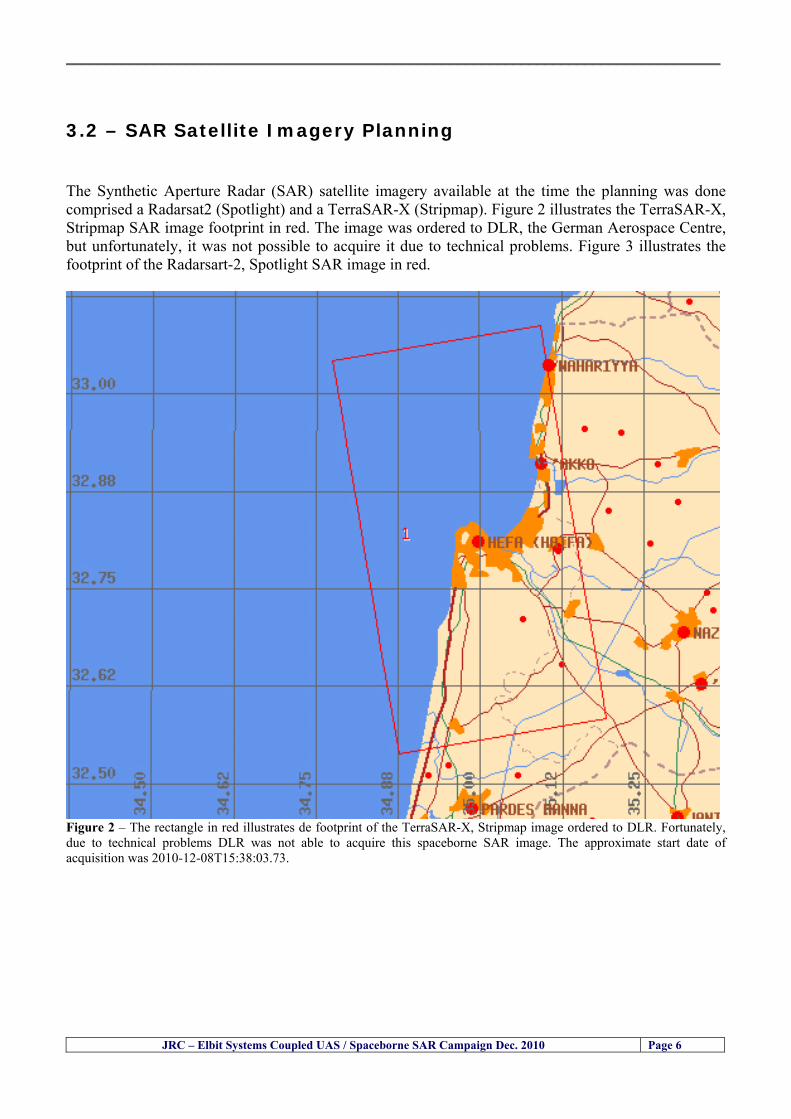
__________________________________________________________________________________
JRC ndash Elbit Systems Coupled UAS Spaceborne SAR Campaign Dec 2010 Page 6
32 ndash SAR Satellite Imagery Planning The Synthetic Aperture Radar (SAR) satellite imagery available at the time the planning was done comprised a Radarsat2 (Spotlight) and a TerraSAR-X (Stripmap) Figure 2 illustrates the TerraSAR-X Stripmap SAR image footprint in red The image was ordered to DLR the German Aerospace Centre but unfortunately it was not possible to acquire it due to technical problems Figure 3 illustrates the footprint of the Radarsart-2 Spotlight SAR image in red
Figure 2 ndash The rectangle in red illustrates de footprint of the TerraSAR-X Stripmap image ordered to DLR Fortunately due to technical problems DLR was not able to acquire this spaceborne SAR image The approximate start date of acquisition was 2010-12-08T15380373
__________________________________________________________________________________
JRC ndash Elbit Systems Coupled UAS Spaceborne SAR Campaign Dec 2010 Page 7
Figure 3 ndash The rectangle in pink illustrates de footprint of the Radarsat-2 Spotlight SAR image ordered to MDA Fortunately due to technical problems DLR was not able to acquire this spaceborne SAR image The approximate start date of acquisition was 2010-12-08T15474000 UTC Table-1 illustrates the SAR satellite images and image modes used in the different days of the experiment
Table 1ndash TerraSAR-X Stripmap and Radarsat2- Spotlight High Resolution 08-Dec-2010 Satellite Evening Satellite Pass 1 TerraSAR-X Stripmap 2010-12-08T15380373 UTC 2 Radarsat-2 Spotlight 2010-12-08T15474000 UTC
__________________________________________________________________________________
JRC ndash Elbit Systems Coupled UAS Spaceborne SAR Campaign Dec 2010 Page 8
The Radarsat2 and TerraSAR-X image modes used in the present experiment will be briefly reviewed in the next paragraphs Radarsat2 - Spotlight Mode ndash The Spotlight Beams are intended for applications which require the best spatial resolution available from the RADARSAT-2 SAR system In this mode the radar operates with the highest sampling rate and so the ground swath coverage is limited to keep data rate within the recorder limits Unlike the other modes Spotlight images are also of fixed size in the along track direction The ser of Spotlight Beams cover any area within the incidence angle range from 20 to 49 degrees Each beam within the set images a swath width of at least 18 km Spotlight images can only be generated in a single polarization which can be either a linear co-polarization (HH or VV) or a linear cross-polarization (HV or VH)
Figure 4 ndash Radarsart2 image modes The Ultrafine and the Spotlight modes have been identified as the most suitable modes for this particular experiment Radarsat2 - Single Beam Mode ndash Single beam mode is a stripmap SAR mode In Single Beam operation the beam elevation and profile are maintained constant throughout the data collection period The following Single Beam modes are available Standard Wide Fine Multi-Look Fine Ultra-Fine Extended High (High Incidence) Extended Low (Low Incidence) Standard Quad Polarization and Fine Quad Polarization We selected Ultra-Fine because it is the best compromise between swath coverage and resolution
__________________________________________________________________________________
JRC ndash Elbit Systems Coupled UAS Spaceborne SAR Campaign Dec 2010 Page 9
Radarsat2 - Ultra-Fine ndash The Ultra-Fine Resolution Beams are intended for applications which require very high spatial resolution In this mode the radar operates with the highest sampling rate and so the ground swath coverage is limited to keep data rate within the incidence angle from 20 to 49 degrees Each beam within the set images a swath width of at least 20 km Ultra-Fine Resolution images can only be generated in a single cross-polarization which can be either a linear co-polarization (HH or VV) or a linear cross-polarization (HV or VH) The standard TerraSAR-X operational mode is the single receive antenna mode from which the following imaging modes can be retrieved High Resolution Spotlight and Spotlight StripMap and ScanSAR The single receive antenna mode uses a chirp bandwidth of up to 300 MHz
Figure 5 ndash Radarsart2 image modes The Ultrafine and the Spotlight modes have been identified as the most suitable modes for this particular experiment The SpotLight (SL) imaging modes use phased array beam steering in azimuth direction to increase the illumination time ie the size of the synthetic aperture This leads to a restriction in the image scene size Thus the scene size is technically restricted to a defined size 10 km x 10 km for the SpotLight mode and 10 km x 5 km (width x length) in the HighResolution SpotLight (HS) mode This sophisticated imaging mode makes it possible to acquire data with up to 1 m resolution in the HighResolution SpotLight mode (acquired with a bandwidth of 300 MHz) and 2 m in the standard SpotLight mode StripMap (SM) is the basic SAR imaging mode as known eg from ERS-1 and other radar satellites The ground swath is illuminated with continuous sequence of pulses while the antenna beam is fixed in elevation and azimuth This results in an image strip with a continuous image quality (in flight direction) StripMap dual polarisation data have a slightly lower spatial resolution and smaller swath than the single polarisation data In StripMap mode a spatial resolution of up to 3 m can be achieved The standard scene size is 30 km x 50 m (width x length) in order to obtain manageable image files however acquisition length is extendable up to 1650 km
__________________________________________________________________________________
JRC ndash Elbit Systems Coupled UAS Spaceborne SAR Campaign Dec 2010 Page 10
33 ndash Partners Involved and their Roles The partners involved in this experiment comprised the European Commission (EC) ndash Joint Research Centre (JRC) and Elbit Systems from Haifa Israel The role of each partner is briefly described next 331 - European Commission (EC) ndash Joint Research Centre (JRC) ndash The main role of the EC-JRC was the planning set up execution and the analysis of the data together with Elbit Systems This comprised
a) the definition of the objectives b) the research methods used c) the ground truth data collection d) the analysis of the data and the conclusions of the experiment
332 ndash Elbit Systems ndash The main role of Elbit Systems comprised
a) the deployment and operation of the boat used as target b) the deployment and operation of the UAS Hermes 450 c) the contacts with the Israeli authorities namely the Israeli Air Force and Civil Aviation
Authority d) the collection of ground truth data e) The analysis of the data and conclusions of the experiment
__________________________________________________________________________________
JRC ndash Elbit Systems Coupled UAS Spaceborne SAR Campaign Dec 2010 Page 11
4 ndash Experiment Execution
41 ndash Modus Operandi The modus operandi of the trial was as follows 1- JRC supplied Elbit Systems with the footprint (frame) of the spaceborne SAR images to be acquired (TerraSAR-X-Stripmap and Radarsat-2 Spotlight) as well as the time of the SAR satellite passes 2- The boat was deployed about 2 nautical miles Southwest of the Port of Haifa The boat was about 12-meter long The boat had a crew of 3 people plus one JRC staff 3- The boat left from the port of Haifa and travelled a couple of nautical miles to reach the test site Once the test site was reached the boat was stationary at the time of the satellite SAR overpass After the satellite overpasses the boat was steered at different speeds to test the tracking capabilities of the UAV
42 ndash Ground Truth Data Collection The ground truth data collected comprised a) the sea state b) Data from the UAS sensors b) the weather conditions and wind speed e) Photos and movies of the boats involved in the experiment
43 ndash Means Involved in the Experiment The means involved in the experiment comprised two satellite SAR images namely a TerraSAR-X-Stripmap and a Radarsat-2 Spotlight and one 12-meter long boat 431 ndash Boat Deployed During the Experiment Figures 6 illustrate the boat deployed as target during the experiment
__________________________________________________________________________________
JRC ndash Elbit Systems Coupled UAS Spaceborne SAR Campaign Dec 2010 Page 12
Figure 6 ndash The 12-meter boat deployed during the experiment at the Port of Haifa Israel 432 ndash Hermes 450 ndash System Overview The Hermesreg UAV system is a mature and operationally proven system with accumulated experience with the Israel Defense Forces operations and with other users worldwide It features a fully redundant architecture leading to a high level of safety and reliability a high level of autonomy modern high performance state-of-the-art payloads and a small logistic footprint Figure 7 shows the main elements of the Hermes UAV System 433 ndash The Air Vehicle Hermesreg 450W is a modern UAV design featuring highly efficient aerodynamics composite structure and a high level of system redundancy and autonomy Its compact size and high maximumempty weight ratio enable very high mission effectiveness delivering potent payloads high endurance and a modest logistic footprint The Hermesreg 450 is in production and has accumulated over 150000 flight hours with the Israeli Air Force and other users around the globe The Hermesreg 450W uses the higher power delivered by the AR802W engine to achieve higher gross weight with the same platform greatly increasing payload and fuel carrying capability a shorter takeoff run and expanded flight envelope
__________________________________________________________________________________
JRC ndash Elbit Systems Coupled UAS Spaceborne SAR Campaign Dec 2010 Page 13
The AR802W engine is a derivative of the AR802 rotary engine with widened rotor and housing The result is a 30 gain in power to nearly 70HP Coupled to an Electronic Fuel Injection system the engine is highly efficient and has improved maintenance figures Following is a summary of the physical characteristics of the Hermes 450W air vehicle is given in Table 2
Table 2 ndash Summary of Hermes 450 main characteristics Physical Characteristics
bull Length 61 m bull Wingspan 105 m bull Fuselage diameter 0508 mm bull Max takeoff weight 550 kg bull Max internal fuel weight (including oil) 115 kg bull Max payload weight 150 kg
Figure 7 ndash Elements of the Hermes UAV System
434 ndash Ground Control Station (GCS) The GCS is a transportable system designed to perform and support all Hermesreg UAV family ground Based activities operational activities These activities include mission planning pre-flight check takeoff and landing UAV flight control mission control payloads and systems control as well as post-mission debriefing An embedded or appended training capability is optional Remote communication of video and telemetry to a C4I center via SATCOM or WAN infrastructure is optional The GCS provides a user friendly comfortable effective and protected environment for carrying out UAV missions
__________________________________________________________________________________
JRC ndash Elbit Systems Coupled UAS Spaceborne SAR Campaign Dec 2010 Page 14
The GCS is housed in a shelter with operator consoles of advanced human engineering design that provide an ergonomic operational environment The shelter is based on the NATO ACE III shelter with a side door As Israelrsquos leading C4I provider Elbit Systems has incorporated Hermesreg GCS advanced C4I capabilities including comprehensive mission planning tactical database management and tactical coordination with supported forces and command elements The Hermesreg GCS is uniquely capable of performing two UAV missions concurrently with two UAVs each of which is controlled via a separate Ground Datalink Terminal (GDT) The Hermesreg GCS requires minimal operating personnel ie mission commander and mission operator
Figure 8 ndash The UAS Hermes 450 Ground Control Station (GCS)
435 ndash The EO Payload The CoMPASS Compact Multi Purpose Advanced Stabilized System is a day and night surveillance system that includes a 3rd generation 3-5 μm zoom FLIR camera a color zoom TV CCD camera and automatic tracking capabilities The CoMPASS enables the following
bull Day and night stabilized LOS observation with capabilities of target detection recognition and identification in various weather conditions
bull Automatic and manual tracking of targets bull Slaving CoMPASS Line of Sight (LOS) to external systems bull LOS information bull Target Laser designationampRanging or only Target Laser Ranging bull Laser Target Marker
__________________________________________________________________________________
JRC ndash Elbit Systems Coupled UAS Spaceborne SAR Campaign Dec 2010 Page 15
CoMPASS the EOIR system for UAV applications is the most advanced payload version of the CoMPASS family featuring reduced weight high degree of modularity and flexibility space-saving packaging and advanced operational and video processing features The CoMPASS based STA Stabilized Turret Assembly is a single LRU housing
bull 3rd generation 3-5 μm FLIR zoom Camera bull Color Zoom TV CCD Camera bull Laser Target Designator bull Laser Target Marker bull Electronic Boards
Figure 9 ndash CoMPASS Stabilized Turret Assembly (STA)
__________________________________________________________________________________
JRC ndash Elbit Systems Coupled UAS Spaceborne SAR Campaign Dec 2010 Page 16
5 ndash Preliminary Data Analysis
51 ndash SAR Satellite Imagery Processing The high resolution spaceborne SAR image was analysed visually because the resolution is good enough to allow visual analysis and the site is too close to the coast which makes automatic processing more difficult and prone to error due to artefacts caused by land targets The Hermes 450 images were also analysed visually
52 ndash Ground Truth Data This section briefly describes the Ground Truth data namely the GPS positions of the boat deployed as target during the experiment a photo of the boat as well as other relevant ground truth data collected
521 ndash GPS coordinates of the boat deployed Table 5 gives the GPS coordinates of the boat deployed during the experiment at the time of the Radarsat-2 satellite overpass Table 3 ndash Ground Truth data collected at the time of the satellite pass (154740 UTC=174740 LT) on 8 December 2010
Date 8 Dec2010 Time 154740 UTC=174740 LT Pass Ascending
SatelliteMode Radarsat-2 Spotlight Polarisation HH
Boats Type Size Latitude Longitude
Elbits 12-meter
Boat
32˚ 51830 N 32deg514980N 32863833deg N
34˚ 57961 E 34deg575766E 34966017deg E
__________________________________________________________________________________
JRC ndash Elbit Systems Coupled UAS Spaceborne SAR Campaign Dec 2010 Page 17
521 ndash HERMES 450 Ground Truth Data Table 4 shows the 12-meter Elbitacutes Boat as detected by the IR sensor of the Hermes 450 Table 4 ndash Hermes 450 Ground Truth Data Date 8 Dec2010 Time 154740 UTC=174740 LT
Platform Hermes 450
UAV Type Size Latitude Longitude
UAV Hermes
450
174730h 3284489947 N
174800h
3285089687 N
174730h 3498564048 E
174800h
3499338667 E
Elbits 12-meter
Boat UAV
Image
32˚ 51830 N 32deg514980N 32863833deg N
34˚ 57961 E 34deg575766E 34966017deg E
53 ndash Weather Conditions and Sea State The weather conditions in Haifa are summarized in Table 5 bellow
Table 5 ndash Wind speed wind direction and Temperature Time (IST) Temp Dew
Point Humidity Pressure Visibility Wind Dir
Wind Speed
Gust Speed Precip Events Conditions
550 PM 210 degC 130 degC 60 1017 hPa - North 111 kmh
31 ms - NA Clear
__________________________________________________________________________________
JRC ndash Elbit Systems Coupled UAS Spaceborne SAR Campaign Dec 2010 Page 18
Figure 10 gives the weather data (Temperature Barometric Pressure Wind Speed and Wind Direction) for Haifa Israel on 8 Dec 2010
Figure 10 ndash Weather data (Temperature Barometric Pressure Wind Speed and Wind Direction) for Haifa Israel on 8 Dec 2010
__________________________________________________________________________________
JRC ndash Elbit Systems Coupled UAS Spaceborne SAR Campaign Dec 2010 Page 19
54 ndash Verification of the Results This section briefly describes the verification of the targets detected in the spaceborne SAR image and in the Hermes 450 UAV using the ground truth data collected during the experiment
541 ndash Overview of the UAV Trajectory and the SAR Imagery Footprint Figure 11 gives an overview of the UAV trajectory the footprint of the SAR imagery and the area of the experiment near the port of Haifa The UAV trajectory is depicted in blue The large red rectangle is the footprint of the TerraSAR-X Stripmap The smaller red rectangle is the footprint of the Radarsat-2 Spotlight image
Figure 11 ndash Google Earth UAV trajectory during the experiment and footprinst of the SAR imagery ordered for the experiment Figure 12 is a zoom in of the previous image which allows a more detailed view of the UAV trajectory and of the port of Haifa Figure 13 is a zoom in of figure 12 It shows in more detail the UAV trajectory during the entire experiment and the port of Haifa in Israel
__________________________________________________________________________________
Figure 12 ndash Zoom in of the previous figure showing a more detailed view of the UAV trajectory and of the port of Haifa in Israel
Figure 13 ndash Zoom in of the previous figure showing a even more detailed view of the UAV trajectory and of the port of Haifa in Israel
JRC ndash Elbit Systems Coupled UAS Spaceborne SAR Campaign Dec 2010 Page 20
__________________________________________________________________________________
JRC ndash Elbit Systems Coupled UAS Spaceborne SAR Campaign Dec 2010 Page 21
542 ndash Targets Detected in the Radarsat-2 Spotlight Image Figure 14 illustrates the position of the Elbitrsquos boat used as target in the experiment at the approximate time of the SAR Satellite pass by 1547 UTC (1747 LT) The small photo of the boat shows the approximate position of the boat The two small planes show the positions of the UAV immediately before and after the SAR Satellite pass
Figure 14 ndash Google Earth positions of the elbitrsquos boat and the UAV (Hermes450) at the approximate time of the SAR Satellite overpass by 174740 UTC Figure 15 shows the corresponding SAR image (Radarsat-2 Spotlight) acquired during the experiment Pins 1 and 2 represent the positions of the UAV before and after the SAR satellite overpass Pin 3 illustrates the position of the Elbitacutes boat deployed at the time of the satellite overpass At this scale the SAR signature of the boat is not distinguishable from the sea clutter background However zooming in the SAR image the SAR signature can clearly be seen as illustrated in figure 12 The SAR image in figure 12 also shows several SAR signatures of large ships in the area at the time of the satellite overpass
__________________________________________________________________________________
JRC ndash Elbit Systems Coupled UAS Spaceborne SAR Campaign Dec 2010 Page 22
Elbit`s Boat
Figure 15 ndash On the background the SAR image with the two UAV positions before and after the satellite overpass (Pin1 and Pin2) and the Elbitacutes Boat position (Pin3) The small window over the SAR image shows a zoom in of the SAR image where the SAR signature of the Elbitacutes Boat can clearly be seen The top right are of the SAR image also shows SAR signatures of several large ships in the area at the time of the SAR satellite overpass Figure 16 shows the corresponding SAR image (Radarsat-2 Spotlight) acquired during the experiment and the UAV IR images of some of the targets Pins 1 and 2 represent the positions of the UAV before and after the SAR satellite overpass Pin 3 illustrates the position of the Elbitacutes boat deployed at the time of the satellite overpass At this scale the SAR signature of the boat is not distinguishable from the sea clutter background However zooming in the SAR image the SAR signature can clearly be seen as illustrated in figure 13 On the top left the UAV IR image of the Elbitrsquos Boat The SAR image in figure 13 also shows several SAR signatures of large ships in the area at the time of the satellite overpass On the centre left the UAV IR image of a large ship On the centre right the UAV IR image of a large ship On the bottom right the UAV IR image of a large ship All the UAV images were acquired at night in complete darkness from altitudes in the order of 5500 meters Nonetheless the quality and detail of the UAV images allows classification of the targets and in some cases the identification As it can be seen the potential of UAV for maritime surveillance is very promising During the experiment the UAV detected all the boats and ships in the area and tracked some of the boatsships to test the tracking capability The capability of detection and tracking targets is a critical capability for maritime surveillance
__________________________________________________________________________________
JRC ndash Elbit Systems Coupled UAS Spaceborne SAR Campaign Dec 2010 Page 23
Elbitacutes Boat
Elbit`s Boat
Figure 16 ndash Zoom-in of figure 15 with the UAV images of some targets On the top left the UAV IR image of the Elbitrsquos Boat On the centre left the UAV IR image of a large ship On the centre right the UAV IR image of a large ship On the bottom right the UAV IR image of a large ship Figure 17 shows a comparison of the SAR and UAV images with an optical photo taken in Haifa Israel a couple of hours before the SAR satellites overpass Most of the large ships were detected in the SAR image and some of these ships can be identified in the optical photo Some of the ships in the photo left the area before the SAR satellites overpass
__________________________________________________________________________________
JRC ndash Elbit Systems Coupled UAS Spaceborne SAR Campaign Dec 2010 Page 24
Figure 17 ndash Photo taken in Haifa Israel a couple of hours before the SAR satellites overpass This phot shows the large ships moored in the area Most of these large ships were detected in the Radarsat-2 image As expected their positions and orientations were slightly different at the time of the satellite overpass
Elbitacutes Boat
Elbit`s Boat
__________________________________________________________________________________
JRC ndash Elbit Systems Coupled UAS Spaceborne SAR Campaign Dec 2010 Page 25
Figure 18 ndash Photo taken in Haifa Israel a couple of hours before the SAR satellites overpass This phot shows the large ships moored in the area Most of these large ships were detected in the Radarsat-2 image As expected their positions and orientations were slightly different at the time of the satellite overpass Figure 18 illustrates the SAR image and the corresponding google earth image of a small pier in the port of Haifa In the SAR image due to several artefacts it is not possible to detect the 7 small boats moored to the small pier The UAR IR image of the same area clearly shows the 7 small boats with impressive detail taking into account that the image was acquired from an altitude of about 5500 meters A zoom in of the same UAV IR image is shown in figure 19 As it can be seen although the image was acquired from an altitude of about 5500 meters the 7 small boats can be clearly seen with enough detail to allow classification of the type of boat A UAV flight at lower altitude would probably giver a lot more detail and eventually allow the identification of the small boats
__________________________________________________________________________________
JRC ndash Elbit Systems Coupled UAS Spaceborne SAR Campaign Dec 2010 Page 26
Figure 19 ndash UAV IR image of a small pier in the port of Haifa Israel where 7 small boats can be seen with enough detail to allow classification This image was acquired from an altitude of about 5500 meters in the dark
__________________________________________________________________________________
55 ndash Quantitative Analysis of the Spaceborne SAR Image In order to allow a quantitative analysis of the data the spaceborne SAR image was calibrated using ESArsquos NEST software package version 4B The input was the SAR image acquired and the output was the Radiometric Calibration (Sigma Naught (σdeg)) expressed in terms of intensity and in decibel (dB) the Radar Brightness (βdeg) and the Radiometric Normalisation (gamma naught (γdeg))
551 ndash Radarsat-2-Spotlight 08Dec2010 (154740 UTC) Haifa Israel Figure 20 illustrates the Intensity band of a subset of the Radarsat-2Spotlgiht image (08Dec2010)
Figure 20 ndash Radarsat-2 Spotlgiht image (08Dec2010) ndash Sigma Naught (Intensity) band
JRC ndash Elbit Systems Coupled UAS Spaceborne SAR Campaign Dec 2010 Page 27
__________________________________________________________________________________
Figure 21 illustrates the Sigma Naught Coefficient of the Radarsat-2 Spotlgiht image (08Dec2010) expressed in terms of intensity and decibel (dB)
Figure 21 ndash Radarsat-2 Spotlgiht image (08Dec2010) - On the left the Sigma Naught (σdeg) (intensity) and on the right the Sigma Naught (σdeg) (dB)
ormalisation amma Naught (γdeg)) of the Radarsat-2 Spotlgiht image (08Dec2010) expressed in dB
-2 Spotlgiht image (08Dec2010) - On the left the Beta Naught (βdeg) and on the right the Gamma Naught (γdeg) (dB)
Figure 22 illustrates the Radar Brightness (Beta Naught (βdeg)) and the radiometric n(G
Figure 22 ndash Radarsat
JRC ndash Elbit Systems Coupled UAS Spaceborne SAR Campaign Dec 2010 Page 28
__________________________________________________________________________________ Figure 23 shows the Sigma Naught (σdeg) in dB after some colour manipulation and the histogram of the Sigma Naught (σdeg) image
Figure 23 ndash Radarsat-2 Spotlgiht image (08Dec2010) - On the top left the Sigma Naught (σdeg) after colour manipulation to enhance the targets and on the top right the corresponding histogram On the bottom we can see the histogram of the image
Table 6 gives the statistics of the Sigma Naught (σdeg) Radarsat-2 Spotlgiht image (08Dec2010) The Sigma Naught (σdeg) range from -72897 dB up to 23465 dB The Mean value is -16855 dB the Median is -16594 dB and the standard deviation is 7077 dB
JRC ndash Elbit Systems Coupled UAS Spaceborne SAR Campaign Dec 2010 Page 29
__________________________________________________________________________________
JRC ndash Elbit Systems Coupled UAS Spaceborne SAR Campaign Dec 2010 Page 30
Table 6 ndash Statistics of the Radarsat-2 Spotlgiht image (08Dec2010) (154740 UTC)
Statistics Values Unit Only ROI-Mask pixels considered Number of pixels total Number of considered pixels Ratio of considered pixels
No 322394283 322394283
1000
Minimum Maximum
-728974609375 234655818939209
intensity_db intensity_db
Mean Median Std-Dev Coefficient of Variation
-16855686580177853 -1659462338617847 707796800831575
07888765273432338
intensity_db intensity_db intensity_db intensity_db
Checking the radar backscattering coefficient of some targets (small boat and some large ships) detected in the Radarsat-2 Spotlight image we get values ranging from -0379 dB up to 23455 dB The analysis of the Sigma Naught values (σdeg) of the targets and the area around the targets shows a significant contrast
56 ndash Summary of the Preliminary Analysis of the Spaceborne SAR Image This experiment involved two spaceborne SAR images namely a TerraSAR-X Stripmap and one Radarsat-2 Spotlight The TerraSAR-X image was not delivered by DLR due to technical problems The Elbitrsquos boat deployed during the experiment was detected in the Radarsat-2 Spotlight image Several other targets including a set of large ships were also detected Table 7 summarises the characteristics of the SAR image acquired and the targets detected
Table 7 ndash List of SAR Satellite Images acquired during the experiment and detected boats ISRAEL (HAIFA)
Date Time Place Satellite Mode Ground Truth Data Detected Boats
08Dec2010 (PM) Haifa - Israel Radarsat-2 Spotlight GPSPhotosMovies 1 small boat deployed + 9 large ships
Table 8 gives the minimum and maximum Sigma Naught (σdeg) of the targets detected in each SAR image
Table 8 ndash Minimum and maximum Sigma Naught (σdeg) of the targets detected in each SAR image
Date Time UTC (LT)Pass Satellite Image Mode Polarisation Sigma Naught (σdeg) Min Max
29Oct2010528UTC(728AM LT) DES Radarsat-2 Spotlight HH --0379 dB 23455 dB The SAR signatures of the boats deployed were very weak Some possible reasons to explain such weak signatures are the sea state the wind speed the incidence angle and the type and materials Another possible reason is the processing at DLR
__________________________________________________________________________________
JRC ndash Elbit Systems Coupled UAS Spaceborne SAR Campaign Dec 2010 Page 31
6 ndash Preliminary Conclusions The analysis of the results of this coupled UASSpaceborne SAR experiment shows a promising potential for the use of UAS for maritime surveillance UAS can be integrated into the airborne building block of maritime surveillance systems to complement the existing assets increase system performance and improve the overall maritime domain awareness The main perceived maritime security and safety threats comprise piracy terrorist and military threats weapons proliferationsmuggling drugs trafficking illegal immigration unlawful use of containers attacks to critical infrastructures and illegal fishing The main maritime security and safety gaps include a lack of technologies with the capability of detecting small targets (eg small boats) a lack of wide area and persistent maritime surveillance a lack of coordination and information sharing limited interoperability a lack of containers security a lack of persistent surveillance of critical infrastructures and early warning systems Unmanned Aircraft Systems (UAS) are an emerging technology with strong potential to mitigate the above mentioned threats by filing in the main maritime security and safety gaps listed earlier For instance the wide range of potential applications of UAS to maritime surveillance includes but is not limited to
bull detection classification and identification of small boats bull persistent maritime surveillance bull use as communications relays bull persistent surveillance of critical infrastructures bull early warning systems bull COMINT and ELINT collection etc
Table 11 illustrates the mapping of maritime securitysafety threats vs gaps and summarises the main potential applications of UAS to maritime surveillance The above mentioned potential applications of UAS to the Maritime Domain will be addressed in turn in more detail next bull Detection classification and identification of small boats ndash The capability of detecting classifying and identifying small targets (eg small boats) is among the key technologies required to improve maritime domain awareness This capability is critical to mitigate piracy illegal immigration drugs trafficking weapons smuggling illegal fishing terrorism and critical infrastructure Unmanned Aircraft Systems (UAS) provide this capability more efficiently and at a lower cost than any other existing technology bull Persistent maritime surveillance ndash With the continuous improvements of UAS technologies such as platforms sensors collision avoidance systems command and control systems telecommunications etc UAS are increasing their autonomy endurance and flexibility These characteristics are very important for persistent maritime surveillance UAS can be launched from land ships aircraft and technologies to launch UAS from submarines are currently under development UAS have distinct advantages over other existing technologies for persistent maritime surveillance in terms of autonomyendurance (the Global Surveyor has an autonomy of 1 week) cost (eg as the autonomy of UAS increases the number of staff required to operate UAS decreases) risk (eg if the UAS crashes the crew is not at risk) flexibility (eg they can be launched from a ship reducing the time to reach potential threats) etc
__________________________________________________________________________________
JRC ndash Elbit Systems Coupled UAS Spaceborne SAR Campaign Dec 2010 Page 32
bull Communications relays ndash UAS are being used as communication relays mainly in military context but have the potential to play a similar role in Civil context in several situations such as to replace satellite communications or as a redundant system over any location on Earth The main advantages of using UAS as communication relays is that airborne communication relays mitigate kinetic and noise jamming threats to satellite communications uplinks by providing an alternative set of links either directly to surface-based terminals or to satellites beyond the range of threats They are less susceptible to noise jamming threats than satellites because an adversary has to detect geolocate and track the airborne asset and operate within line of sight of the receive antenna main beam bull Persistent surveillance of critical infrastructures ndash The security of critical infrastructures such as nuclear power plants refineries ports etc requires persistent surveillance UAS can play an important role in providing persistent surveillance over critical infrastructures and over a wide area around the critical infrastructure Some advantages of UAS over other existing technologies such as ground-based assets (eg video cameras alarm systems manned aircraft etc) comprise the security of the UAS (eg hardly can be damaged or switched off as any ground-based asset) the area covered by a UAS (eg it is larger than the area covered by any ground-based asset) the cost (eg UAS is cheaper than manned aircraft with similar capability) etc bull Early warning systems ndash UAS have the potential to be used as part of an integrated system of systems for early warning A UAS can provide information about a given area at a fraction of the cost of alternative means Formation flying of UAS can cover a wide maritime area It is reasonable to assume that in a foreseeable future with the advent of UAS with increased autonomy the operations cost of UAS will likely decrease making them increasingly more attractive bull COMINT and ELINT collection ndash SIGNal INTelligence (SIGNINT) can be divided into two categories namely COMINT and ELINT COMINT stands for Communication Intelligence and ELINT for Electronic Intelligence Collection of COMINT is passive Exploitation of COMINT requires a human operator which implies COMINT UAS are suitable for COMINT and ELINT collection in different scenarios The relatively reduced amount of data collected and analysed during this experiment and the lessons learned do not allow drawing final conclusions about the feasibility of using Unmanned Aerial Systems (UAS) for maritime surveillance However this experiment allowed hands-on experience with UAS technologies and significantly improved the awareness for its applications to maritime surveillance and related issues involved including its potential the feasibility as well as the limiting and enabling factors These different aspects will now be analysed in turn in the next sections Table 11 illustrates the mapping of the main maritime security threats and gaps as well as the main priorities in terms of the different technologies involved in maritime surveillance For each maritime threat the technologies required to fill in each gap is indicated and its priority is expressed in a range of numbers (1 to 3 1 = Maximum Priority 2 = Medium Priority 3 = Low Priority) and colours (Red = Maximum Priority Orange = Medium Priority Green = Low Priority) The main technologies involved in maritime surveillance are listed on the bottom of figure 4 and are reproduced here for convenience of the reader 1- Reporting Systems 2- Sensors 3- Platforms 4- Communications 5- Data Fusion amp Sharing 6- Intelligence and 7- Databases For example the mitigation of the main threat Piracy requires filling in several maritime security gaps (eg lack of persistent surveillance lack of wide-are maritime surveillance lack of small boat detection lack of Early Warning Systems and lack of Information Sharing with maximum priority (1- Red) and among the required technologies listed are UAS LTAAV GEO-HR etc Concerning the remaining two gaps (Limited Interoperability and Containers Security) they are less relevant to mitigate Piracy hence the priority for Limited Interoperability is 2-Orange and for Containers Security is 3- Green
__________________________________________________________________________________ Table 9 ndash The Main Maritime Security and Safety Threats vs Gaps and the technologies that can be used to mitigate them
Maritime Security Main Threats GapsGapsrarr
darrThreats
Lack o f Risk As sessmentCapab ility
La ck of Persiste nt
Surveilla nce
La ck of Wid e-Area su rve illanc e
La ck of Small Boat De tecti on
Lack o f Earl y Warn ing Sys tems
L ack of In forma tion
Sh arin g
L imi ted In terop era bility
Lac k of Co ntai ners
Se cur ity
bull PiracyUAS LTAVG EO-
HR + UAS LT AVGEO-
HR + SAR GEO-HR
+ UAS USV LTAV
+ UAS LTAV
+ Coord in ationamp Sharing +
Inter opera bilityOptimisation +
1 2 3 5 6 7 1 2 3 5 6 7 1 2 3 5 6 1 2 3 123456 4567 1234567 1234567
bull Terro rismUAS LTAVG EO-
HR + UAS L TAV GEO-HR +
SAR AISGEO-HR +
UAS USV LTAV+
Intelligence+
Inte lligen ce+
Inter opera bilityOptimisation +
Intelligence+
1 2 3 5 6 7 1 2 3 5 6 1 2 3 5 6 1 2 3 123456 4567 1234567 1234567
bull Wea pon s ofM ass Dest ru ctio n Smugg ling
UAS LTAVG EO-HR +
UAS LT AVGEO-HR +
SAR AIS+
UAS USV LTAV+
Intelligence+
Inte lligen ce+
Intelligence+
Intelligence+
1 2 3 5 6 7 1 2 3 5 6 1 2 3 5 6 1 2 3 123456 4567 1234567 1234567
bull Drug sTraffic king
UAS LTAVG EO-HR +
UAS LT AVGEO-HR +
SAR AIS+
UAS USV LTAV+
Intelligence+
Inte lligen ce+
Intelligence+
Intelligence+
1 2 3 5 6 7 1 2 3 5 6 1 2 3 5 6 1 2 3 123456 4567 1234567 1234567
bull Illega lImmigratio n
UAS LTAVG EO-HR +
UAS LT AVGEO-HR +
SAR AIS+
UAS USV LTAV+
Intelligence+
Inte lligen ce+
Intelligence+
Intelligence+
1 2 3 5 6 7 1 2 3 5 6 1 2 3 5 6 1 2 3 123456 4567 1234567 1234567
bull Critic alI nfrastruc tureSecu rit y
UAS LTAVG EO-HR +
UAS LT AVGEO-HR +
SAR AIS+
UAS USV LTAV+ + Inte lligen ce
+ Intelligence
+ Intelligence
+
1 2 3 5 6 7 1 2 3 6 1 2 3 5 6 1 2 3 123456 4567 1234567 1234567
bull Illega lFish ing
UAS LTAVG EO-HR +
AI S+SAR UASLTAV +
SAR AIS GEO-HR+
UAS USV LTAV+
Intelligence+
Inte lligen ce+
Intelligence+
1 2 3 5 6 7 1 2 3 5 7 1 2 3 5 6 1 2 3 123456 4567 1234567
bull Un lawf ul Use of Co nta iners
(Secur ity)
UAS LTAVG EO-HR +
GPS Tr acking+
Intelligence+
Inte lligen ce+
GPS Int rusion Det ection Se al
1 2 3 5 6 7 4 6 7 1 2 3 5 6 1 2 3 123456 4567 1234567 1234567
(-) Priority (+) Not Rel evant
SURVEILLANCETECHNOLOGIES
1- Reporti ng Systems
2 -Sensors 3 -P latforms 4 - Communications 5- Data Fusionamp Sharing
6 -I ntelli gence 7 -Databases
JRC ndash Elbit Systems Coupled UAS Spaceborne SAR Campaign Dec 2010 Page 33
__________________________________________________________________________________
JRC ndash Elbit Systems Coupled UAS Spaceborne SAR Campaign Dec 2010 Page 34
61 ndash Hands-on experience with UAS technologies and its applications to maritime surveillance This coupled UASSpaceborne SAR campaign was a unique opportunity to acquire further handsndashon experience with UAS technologies and learn about the main issues related to its applications to maritime surveillance From the planning phase up to the execution of the UAS flight and landing there are several factors that need to be carefully analysed and taken into account A summary of the main issues identified in this experiment is given next 1- Selection of the Experiment Area Authorisation to Fly ndash For the time being UAS can only be flown in restricted areas usually under control of national authorities often the military This is due to the risks that a UAS can pose to human life and property In the present case an area under the authority of the Israeli Civil Aviation Authority was selected The authorisation to fly was not easy to obtain because the selected area is under the authority of the Civil Aviation Authority Figure 24 indicates the area of the experiment in Haifa Israel 2- UAS Communications Issues ndash The Hermes 450 was flown in Line-of-Sight (LOS) since it was close to the coast For BLOS (Beyond Line-of-Sight) operation satellite communications are required 3- Synthetic Aperture Radar (SAR) ndash The specific model Hermes 450W used in the experiment had no SAR sensor installed However a SAR sensor can be installed A SAR sensor is important for maritime surveillance since it allows 247 operations regardless of the weather conditions 4- Automatic Identification System (AIS) Receiver ndash The Hermes 450 used in this experiment was not equipped with an AIS receiver For maritime surveillance operations an AIS receiver is a very important tool since it allows the automatic identification of most ships allowing the UAS to concentrate on non-identified ships
__________________________________________________________________________________
Figure 24 ndash The area of the experiment is indicated by the GPS Trajectory of the UAV
62 ndash Potential of UAS for Maritime Surveillance UAS technologies are relatively recent and involve a wide range of fields spanning from aeronautics and sensors technologies to satellite communications and other engineering disciplines Innovations in each of the fields involved are emerging by the day UAS still have a long way to go before they become mature and their use fully operational For the time being UAS are mainly used for military applications However a large number of non-military UAS applications have been identified by stakeholders and there are several studies and demonstration flights foreseen for the near future Maritime surveillance is one of the most challenging and promising fields of application of UAS The challenges are due to the very demanding conditions under which the UAS must operate over sea and the requirements for safe operation
JRC ndash Elbit Systems Coupled UAS Spaceborne SAR Campaign Dec 2010 Page 35
__________________________________________________________________________________
JRC ndash Elbit Systems Coupled UAS Spaceborne SAR Campaign Dec 2010 Page 36
The present UAS experiment has unveiled some of the potential of UAS for maritime surveillance The UAS tests performed during this experiment include
1 ndash Detection of a Small rubber Boat and a Fishing Ship 2 ndash Tracking of a Small Boat and a Fishing Ship 3 ndash Classification of a Small Boat and a Fishing Ship 4 ndash Identification of a Small Boat and a Fishing Ship 5 ndash Detection and Tracking of People on the Beach
Despite the operational requirement that prevented the UAS from flying bellow 3km the experiment has confirmed the capability of UAS for small boat detection tracking and classification as well as the capability for people detection and tracking Concerning the identification of the targets the characteristics of the images acquired during this mission suggest that flying at lower altitudes the UAS images would allow the identification of the targets The UAS images can be seen from Figure 15 to 20
621 ndash Advantages of UAS for maritime Surveillance Some of the advantages of using UAS for maritime surveillance have been described in the literature and are summarized bellow
1- One potential benefit of UAS is that they could fill in a gap in current maritime surveillance by improving coverage
2- The range of UAS is a significant asset when compared to border agents on patrol or stationary surveillance equipment
3- Eletro-Optical InfraRed (EOIR) sensors (cameras) can identify small size objects from very high altitudes (high resolution)
4- UAS can provide precise and near-real-time imagery to a ground control operator who would then disseminate that information so that informed decisions regarding the deployment of border patrol agents can be made quickly
5- Long endurance UAS used along the border can fly for more than 30 hours up to several days without having to refuel compared with manned helicopterrsquos average flight time of just over 2 hours
6- The ability of UAS to loiter for prolonged periods of time has important operational advantages over manned aircraft
7- The longer flight times of UAS means that sustained coverage over a previously exposed area may improve maritime security
8- The range of UAVs is a significant asset when compared to border agents on patrol or stationary surveillance equipment Nevertheless the extended range and endurance of UAVs may lessen the burdens on human resources at the borders
9- UAS accidents do not risk the lives of pilots as do the helicopters and aircraft currently used by Coast Guards for border patrolling
__________________________________________________________________________________
JRC ndash Elbit Systems Coupled UAS Spaceborne SAR Campaign Dec 2010 Page 37
622 ndash Possible Drawbacks of using UAS for maritime Surveillance UAS also have disadvantages some of them are briefly described next
1- There have been concerns regarding the high accident rate of UAS which can be multiple times higher than that of manned aircraft Because UAS technology is still evolving there is less redundancy built into the operating system of UAS than of manned aircraft and until redundant systems are perfected mishap rates are expected to remain high
2- If control systems fail in a manned aircraft a well-trained pilot is better positioned to find the source of the problem because of hisher physical proximity If a UAS encountered a similar system failure or if a UAS landing was attempted during difficult weather conditions the ground control pilot would be at a disadvantage because he or she is removed from the event Unlike a manned pilot the remote pilot would not be able to assess important sensory information such as wind speed
3- Inclement weather conditions can also impinge on a UAS surveillance capability especially UAS equipped with only an EO camera and Forward Looking Infrared Radar (FLIR) because cloudy conditions and high humidity climates can distort the imagery produced by EO and FLIR equipment The effects of extreme climatic or atmospheric conditions on sensors reportedly can be mitigated with the outfit of one synthetic aperture radar (SAR) system and a moving target indicator (MTI) radar However adding SAR and MTI to a UAS platform would increase the costs associated with using UAS
4- Depending on the type of UAS the costs of operating a UAS can be higher than the costs of operating a manned aircraft This is because some types of UAS require a significant amount of logistical support and specialized operator and maintenance training Operating one UAS may require a crew of up to 20 support personnel The high comparative costs of operating some sophisticated types of UAS may be offset somewhat by their comparatively lower unit costs
63 ndash Main Limiting Factors Preventing the Use of UAS Several pre-requisites must be satisfied to render the UAS a viable cost-effective and regulated alternative to existing resources Major civil and commercial market barriers include
Single European Sky Sense and Avoid technologies Command and Control Technologies Reliability Communications (Bandwidth LOS BLOS)
Lack of airspace regulation that covers all types of UAV systems (encompassing lsquosense and avoidrsquo airspace integration and airworthiness issues)
Affordability - price and customization issues (eg commercial off-the-shelf open modular architecture) Lack of efforts to establish joint customer requirements (although this is gradually changing) Liability for civil operation Capacity for payload flexibility Lack of sufficient secure non-military frequencies for civil operation Perceived reliability (eg vehicle attrition rate vs manned aircraft) Operator training issues Recognitioncustomer perception of the UAV market Technology developments for multi-mission capability
__________________________________________________________________________________
64 ndash UAS Key Enabling Technologies Figure 25 illustrates the components of a typical UAV System showing some of the capabilities needed and the enabling technologies required for performing a given mission Any UAV mission involves many capabilities and technologies Due to the depicted system complexity the main key players such as the US Department of Defense (DoD) and other agencies have started to use the term Unmanned Aerial System (UAS) in place of UAV
Figure 25 ndash Unmanned Aerial Vehicle System Enabled by Autonomous Mission Management Reliable Flight Systems Navigation Accurate Systems Terrain Avoidance Power and Propulsion Some UAS key enabling technologies are listed below
Autonomous Mission Management Collision Avoidance Intelligent System Health Monitoring
Reliable Flight Systems Sophisticated Contingency Management Intelligent Data Handling and Processing Over-the-Horizon Communication Network-Centric Communication Open Architecture Power and Propulsion Navigation Accurate System Technology Enhanced Structures
JRC ndash Elbit Systems Coupled UAS Spaceborne SAR Campaign Dec 2010 Page 38
__________________________________________________________________________________
JRC ndash Elbit Systems Coupled UAS Spaceborne SAR Campaign Dec 2010 Page 39
Table 12 gives a more detailed description of other critical technologies for emerging autonomous UAV systems both civil and military Most of the technologies mentioned in Table 12 apply both to civil and military UAV systems Table 10 ndash Key Enabling Technologies (from SG75 study on autonomous systems)
Critical Technologies Decision Making Software
bull Fuzzy-based decision making bull Knowledge-based system bull Case-based reasoning bull Self-learning techniques bull Decision tree evaluation bull ReasoningInferring bull Probabilisticstochastic reasoning
Prediction Algorithms bull Predictive pathintent algorithms bull Short reaction algorithm bull Effectiveness evaluation
Status Assessment Software bull Internal status analysis bull Self-orientation
Situation Analysis Software bull Situation analysis bull Environmental analysis bull External status analysis
Modelling Software bull Air vehicle modelling algorithms bull Sensor modelling algorithms bull Scenario generation bull Threat system modeling bull Attack simulation bull Mission success optimisation model bull Simulation
Sensor Processing Software bull Sensor fusion bull Area of interest identification bull Automatic target recognition
Adaptive and Self-learning Systems bull Failure self-compensation
Attack Planning Software bull Attack plans and tactical alternatives bull Plan change impact identification
Weapon Engagement Procedure Software bull Weapon engagement algorithms
Mission Plan Update Software bull Route planning system bull Payload plan management system bull Mission Success Optimisation model
Path Optimisation Software bull Optimal trajectory planning bull Path Optimisation System
Targeting Software bull Target tracking bull Target prioritisation
Platform Technologies bull Obstacle detection and avoidance (airborne) bull Obstacle detection and avoidance (ground) bull Improved autopilot bull Speech recognition
Figure 26 summarises system element designs needed to transition from current to next-generation autonomous UAV systems for civilian and military UAS
__________________________________________________________________________________
Figure 26 ndash System Element Designs Needed to Transition from Current to Next-Generation Autonomous UAV Systems These new paradigms are a combination of system attributes and technological capabilities For instance the data fusion secure anti-jam and coordinated multi-vehicle control require technological development as well as specific system development to bring full maturity to unmanned systems Finally very small Micro UAVs (MAVs) and relatively large sophisticated UCAV systems are examples of the range of UAVs that are applying the new platforms payloads onboard processing communications etc to create next generation automated UAVs It is with these new platforms payloads etc that both UCAVs and MAV will be able to address similar operational challenges including
Mixed operation with other assets bull Deconfliction collision avoidance C4I integration
Operation over populated areas bull Safety issues Need to reduce reliance on communications bull UCAV ndash countermeasures bull MAV ndash limited size and power bull Limited line of sight environment Need a fully integrated system bull MAV propulsionpower generation still critical bull Operator machine interface critical bull All weather operations bull Survivability
JRC ndash Elbit Systems Coupled UAS Spaceborne SAR Campaign Dec 2010 Page 40
__________________________________________________________________________________
JRC ndash Elbit Systems Coupled UAS Spaceborne SAR Campaign Dec 2010 Page 41
65 ndash Mission Readiness
651 ndash Mission Readiness Summary This section summarises civil UAV mission readiness The purpose of Mission Readiness is to assess the readiness status of the different technologies involved in UAS In the present case this civil UAV mission readiness based on technology maturation forecasts that meet or exceed the desired or required capabilities identified by the user community Figure 27 summarises the mission readiness time forecasts for the different technologies The technologies annotated with an asterisk () are shown within the figure with maturation forecasts based on development targets expressed in the US Department of Defencesrsquo UAV Roadmap document The purpose of the chart is to be able to identify when the capability to fly a particular mission can be expected as a function of time The left-most end is the least probable and the right end the most probable timeframe
Figure 27 ndash Technology Maturation Summaries in Terms of Mission-Derived Capabilities
__________________________________________________________________________________
JRC ndash Elbit Systems Coupled UAS Spaceborne SAR Campaign Dec 2010 Page 42
66 ndash Small Boat Detection in SAR Satellite Imagery The use of spaceborne SAR imagery for small boat detection requires additional small boat detection experiments under different conditions using different methods It is not possible to draw final conclusions based on a limited number of small boat detection experiments which are not representative of the multiple possible scenarios
67 ndash Limitations of current State-of-the-Art SAR Satellite technology The main limitations of current State-of-the-Art spaceborne SAR imagery for maritime surveillance in particular aimed at small boat detection are 1 - SAR satellites repeat cycles do not allow the coverage of the same area at the required time intervals Constellations of SAR satellites could be a solution 2 - The conflict between resolution and image swath High resolution is required to detect small boats However the high resolution images have small swaths Maritime surveillance with high resolution images would require a large number of images to cover wide maritime areas which is very expensive and for the time being technically not feasible Intelligence data can play an important role by indicating an approximate position of suspicious non cooperative targets therefore reducing the surveillance area which can then be imaged using high resolution images 3- Spaceborne high resolution SAR imagery acquisition times are long enough to allow significant motion of the target during the acquisition time degrading the quality of the image Further research efforts are needed to develop new sensors and platforms As far as sensors are concerned shorter integration times are needed to prevent the blurring effect caused by the motion of the targets Regarding the platforms more platforms are needed to allow lower repeat cycles and improved coverage
__________________________________________________________________________________
JRC ndash Elbit Systems Coupled UAS Spaceborne SAR Campaign Dec 2010 Page 43
7 ndash Plans for Future Work The controlled experiments carried out by the EC-JRC together with Elbit Systems in Haifa-Israel comprised the deployment of a UAS (Hermes-450) and one small 12-meter boat A Radarsat-2 Spotlight image was acquired and several images collected by the Hermes-450 The experiment unveiled the potential of UAS for maritime surveillance in particular for detection tracking classification and possible identification of small targets The UAS was able to detect track and classify small targets such as small boats For low UAS altitude flights identification may be possible in some cases The small 12-meter boat was detected in the spaceborne SAR image The small boat detection trials carried out by the JRC were very successful since most small boats deployed during the experiments were detected in different sea states wind speeds and geographical locations The several small boat detection campaigns conducted by the EC-JRC seem to suggest that the probability of detection of small boats in spaceborne SAR images strongly depends on factors such as the sea state the wind speed the type of boat (shape and materials) the weather conditions among other factors The results of the experiments conducted thus far are not enough to draw final conclusions about the feasibility of using spaceborne SAR imagery for small boat detection However the experiments have an overall positive outcome because they indicate that under suitable sea state and wind speed conditions it is possible to detect small boats using spaceborne SAR The estimation of the probability of detection of small boats in spaceborne SAR images requires a large number of experiments under different circumstances (eg sea state wind speed characteristics of the targets image type and mode etc) Future plans include additional UAS experiments to asses its potential for maritime surveillance
Acknowledgements ndash The authors would like to express their gratitude to Elbit Systems for their cooperation logistical support and assets deployed without which the present coupled UASSAR Satellite Small Boat Detection Campaign would have not been possible
__________________________________________________________________________________
JRC ndash Elbit Systems Coupled UAS Spaceborne SAR Campaign Dec 2010 Page 44
REFERENCES [1] Elbit Systems ldquoUAV Elbit Systems Proposal for Unmanned Aerial Vehicle (UAV) flight to
collect Ground Truth data during a Maritime Surveillance Campaign and demonstrate UAV capabilities for Maritime Surveillancerdquo 2010
[2] ndash Cheryl Yuhas Suborbital Science Program Manager NASA Science Mission Directorate ldquoEarth Observations and the Role of UAVs A Capabilities Assessment Version 11rdquo Civil UAV Assessment Team httpwwwnasagovcentersdrydenresearchcivuavindexhtml August 2006
[3] ndash Document NIAG (SG75) NATO Industrial Advisory Group Study Group 75 Pre-Feasibility Study on UAV Autonomous Operations 2004
[4] ndash United States Department of Defence (DoD) Directive 50001 ldquoThe Defense Acquisition Systemrdquo and DoD Instruction 50002 ldquoOperation of the Defense Acquisition Systemrdquo
[5] ndash Mr James Ramage Mr Massimo Avalle Dr Erik Berglund Dr Luigi Crovella Mr Robert Frampton Dr Uwe Krogmann Mr Christian Ravat Mr Mike Robinson Dr Axel Schulte Dr Scott Wood ldquoRTO-TR-SCI-118 - Automation Technologies and Application Considerations for Highly Integrated Mission Systemsrdquo RTO-TR-SCI-118 AC323(SCI-118)TP204 January 2009
[6] Victor MG Silva Gilles Jurquet Gabriel Marchalot Maria TG Calzado Txema Soroa Juan Sancho Adam Koubek Harm Greidanus and Claudio Savarino ldquoWide Maritime Area Airborne Surveillance (WIMA2S) WP5 Final Reportrdquo WIMAAS WP5 FP7 Project 2008-2011 - ISBN-978-92-79-22801-8 (print) 978-92-79-22802-5 (PDF) ISSN-1018-5593 (print) 1831-9424 (online) EC-JRC Scientific Report JRC 70093 2012
[7] Victor MG Silva and Harm Greidanus ldquoSpaceborne SAR Small Boat Detection Campaign in Portugal and Spainrdquo EUR 25281 EN ISBN 978-92-79-22553-6 ISSN 1831-9424 (online) EC-JRC Scientific Report JRC68160 2012
[8] Goncalves Da Silva V Van Wimersma Greidanus H Hejmanowska B Loudjani P ldquoUAS Applications With Societal Benefits ndash JRCrsquos UAS-Related Activitiesrdquo 2011-2012 UAS Yearbook - UAS Unmanned Aircraft Systems - The Global Perspective 9 (9) 2011 p 127-129 JRC66600
[9] Goncalves Da Silva V Van Wimersma Greidanus H ldquoSmall boat detection using TerraSAR-X and Radarsat2 satellite imageryrdquo 4th TerraSAR-X Science Team Meeting 14 February 2011 DLR Oberpfaffenhofen (Germany) German Aerospace Center (DLR) (Organiser) 2011 JRC63663
[10] V Silva Harm Greidanus ldquoJRC - SAR Satellite Small Boat Detection Campaign - Portoroz ndash Sloveniardquo - ISBN-13 978-92-79-21476-9 ISSN (online) 1831-9424 EC-JRC Scientific Report JRC66835 2011
[11] V Silva Harm Greidanus ldquoJRC - SAR satellite small boat detection campaign - Algarve Portugalrdquo - ISBN-13 978-92-79-21265-9 ISSN (online) 1831-9424 ISSN (print) 1018-5593 EC-JRC Scientific Report JRC66631 2011
[12] ndash Goncalves Da Silva V Van Wimersma Greidanus H ldquoJRC-Frontex Spaceborne SAR Small Boat Detection Campaign ndash Italy amp Spainrdquo - ISBN-13 978-92-79-22213-9 ISSN (online) 1831-9424 EC-JRC Scientific Report JRC67517 2011
[13] - PW Vachon SJ Thomas J Cranton HR Edel and MD Henschel Validation of ship detection by the RADARSAT synthetic aperture radar and the Ocean Monitoring Workstation Canadian Journal of Remote Sensing 26(3)200ndash212 2000
[14] - Crisp D (2004) The state-of-the-art in ship detection in Synthetic Aperture Radar imagery DSTO Information Sciences Laboratory Australia
[15] - Joint Research Centre (JRC) of the European Community mdash IMPAST and DECLIMS web site httpintelligencejrcceceuintmarinefishindexhtm
[16] - McCandless SW Jackson CR (2004) Principles of Synthetic Aperture Radar Synthetic Aperture Radar Marine Users Manual NOAA Washington pp 1-23
[17] - Greidanus H (2008) Satellite Imaging for Maritime Surveillance of the European Seas Remote Sensing of the European Seas 343-358
European Commission
EUR 25346 EN --- Joint Research Centre --- Institute for the Protection and Security of the Citizen
Title JRC --- Elbit Systems Coupled UAS and Spaceborne SAR Campaign in Israel
Authors Victor MG Silva Harm Greidanus
Luxembourg Publications Office of the European Union
2012 --- v+44 pp --- 210 x 297 cm
EUR --- Scientific and Technical Research series --- ISSN 181-9424 (online) ISSN 1018-5593 (print)
ISBN 978-92-79-25020-0
doi10278828527
Abstract The European maritime area is one of Europersquos most important assets with regard to resources security and ultimately
prosperity of the Member States A significant part of Europersquos economy relies directly or indirectly on it It is not just the
shipping or fisheries industries and their related activities It is also shipbuilding and ports marine equipment and offshore
energy maritime and coastal tourism aquaculture submarine telecommunications blue biotech and the protection of the
marine environment The European maritime area faces several risks and threats posed by unlawful activities such as drugs
trafficking smuggling illegal immigration organised crime and terrorism Piracy in international waters also constitutes a threat
to Europe since it can disrupt the maritime transport chain These risks and threats can endanger human lives marine resources
and the environment as well as significantly disrupt the transport chain and global and local security It is anticipated that these
risks and threats will endure in the mid and long run In order to keep Europe as a world leader in the global maritime economy
an effective integratedinteroperable sustainable maritime surveillance system and situational awareness are needed
A significant number of unlawful maritime activities such as illegal immigration drugs trafficking smuggling piracy and
terrorism involve mainly small boats because small boats are faster and more difficult to detect using conventional means
Hence it is very important to find out the feasibility of using Unmanned Aerial Systems (UAS) for small boat detection tracking
classification and identification as well as to study the potential of UAS for maritime surveillance Since 2010 the EC-JRC has
carried out a number of UAS maritime surveillance campaigns to study the potential of UAS for maritime surveillance in
particular for small boat detection This report presents the results and conclusions of the JRC --- Elbit Systems Coupled UAS and
Spaceborne SAR campaign carried out in Dec 2010 in Haifa Israel
As the Commissionrsquos in-house science service the Joint Research Centrersquos mission is to provide EU policies with independent evidence-based scientific and technical support throughout the whole policy cycle Working in close cooperation with policy Directorates-General the JRC addresses key societal challenges while stimulating innovation through developing new standards methods and tools and sharing and transferring its know-how to the Member States and international community Key policy areas include environment and climate change energy and transport agriculture and food security health and consumer protection information society and digital agenda safety and security including nuclear all supported through a cross-cutting and multi-disciplinary approach
LB-NA-25346-EN
-N
__________________________________________________________________________________
JRC ndash Elbit Systems Coupled UAS Spaceborne SAR Campaign Dec 2010 Page 7
Figure 3 ndash The rectangle in pink illustrates de footprint of the Radarsat-2 Spotlight SAR image ordered to MDA Fortunately due to technical problems DLR was not able to acquire this spaceborne SAR image The approximate start date of acquisition was 2010-12-08T15474000 UTC Table-1 illustrates the SAR satellite images and image modes used in the different days of the experiment
Table 1ndash TerraSAR-X Stripmap and Radarsat2- Spotlight High Resolution 08-Dec-2010 Satellite Evening Satellite Pass 1 TerraSAR-X Stripmap 2010-12-08T15380373 UTC 2 Radarsat-2 Spotlight 2010-12-08T15474000 UTC
__________________________________________________________________________________
JRC ndash Elbit Systems Coupled UAS Spaceborne SAR Campaign Dec 2010 Page 8
The Radarsat2 and TerraSAR-X image modes used in the present experiment will be briefly reviewed in the next paragraphs Radarsat2 - Spotlight Mode ndash The Spotlight Beams are intended for applications which require the best spatial resolution available from the RADARSAT-2 SAR system In this mode the radar operates with the highest sampling rate and so the ground swath coverage is limited to keep data rate within the recorder limits Unlike the other modes Spotlight images are also of fixed size in the along track direction The ser of Spotlight Beams cover any area within the incidence angle range from 20 to 49 degrees Each beam within the set images a swath width of at least 18 km Spotlight images can only be generated in a single polarization which can be either a linear co-polarization (HH or VV) or a linear cross-polarization (HV or VH)
Figure 4 ndash Radarsart2 image modes The Ultrafine and the Spotlight modes have been identified as the most suitable modes for this particular experiment Radarsat2 - Single Beam Mode ndash Single beam mode is a stripmap SAR mode In Single Beam operation the beam elevation and profile are maintained constant throughout the data collection period The following Single Beam modes are available Standard Wide Fine Multi-Look Fine Ultra-Fine Extended High (High Incidence) Extended Low (Low Incidence) Standard Quad Polarization and Fine Quad Polarization We selected Ultra-Fine because it is the best compromise between swath coverage and resolution
__________________________________________________________________________________
JRC ndash Elbit Systems Coupled UAS Spaceborne SAR Campaign Dec 2010 Page 9
Radarsat2 - Ultra-Fine ndash The Ultra-Fine Resolution Beams are intended for applications which require very high spatial resolution In this mode the radar operates with the highest sampling rate and so the ground swath coverage is limited to keep data rate within the incidence angle from 20 to 49 degrees Each beam within the set images a swath width of at least 20 km Ultra-Fine Resolution images can only be generated in a single cross-polarization which can be either a linear co-polarization (HH or VV) or a linear cross-polarization (HV or VH) The standard TerraSAR-X operational mode is the single receive antenna mode from which the following imaging modes can be retrieved High Resolution Spotlight and Spotlight StripMap and ScanSAR The single receive antenna mode uses a chirp bandwidth of up to 300 MHz
Figure 5 ndash Radarsart2 image modes The Ultrafine and the Spotlight modes have been identified as the most suitable modes for this particular experiment The SpotLight (SL) imaging modes use phased array beam steering in azimuth direction to increase the illumination time ie the size of the synthetic aperture This leads to a restriction in the image scene size Thus the scene size is technically restricted to a defined size 10 km x 10 km for the SpotLight mode and 10 km x 5 km (width x length) in the HighResolution SpotLight (HS) mode This sophisticated imaging mode makes it possible to acquire data with up to 1 m resolution in the HighResolution SpotLight mode (acquired with a bandwidth of 300 MHz) and 2 m in the standard SpotLight mode StripMap (SM) is the basic SAR imaging mode as known eg from ERS-1 and other radar satellites The ground swath is illuminated with continuous sequence of pulses while the antenna beam is fixed in elevation and azimuth This results in an image strip with a continuous image quality (in flight direction) StripMap dual polarisation data have a slightly lower spatial resolution and smaller swath than the single polarisation data In StripMap mode a spatial resolution of up to 3 m can be achieved The standard scene size is 30 km x 50 m (width x length) in order to obtain manageable image files however acquisition length is extendable up to 1650 km
__________________________________________________________________________________
JRC ndash Elbit Systems Coupled UAS Spaceborne SAR Campaign Dec 2010 Page 10
33 ndash Partners Involved and their Roles The partners involved in this experiment comprised the European Commission (EC) ndash Joint Research Centre (JRC) and Elbit Systems from Haifa Israel The role of each partner is briefly described next 331 - European Commission (EC) ndash Joint Research Centre (JRC) ndash The main role of the EC-JRC was the planning set up execution and the analysis of the data together with Elbit Systems This comprised
a) the definition of the objectives b) the research methods used c) the ground truth data collection d) the analysis of the data and the conclusions of the experiment
332 ndash Elbit Systems ndash The main role of Elbit Systems comprised
a) the deployment and operation of the boat used as target b) the deployment and operation of the UAS Hermes 450 c) the contacts with the Israeli authorities namely the Israeli Air Force and Civil Aviation
Authority d) the collection of ground truth data e) The analysis of the data and conclusions of the experiment
__________________________________________________________________________________
JRC ndash Elbit Systems Coupled UAS Spaceborne SAR Campaign Dec 2010 Page 11
4 ndash Experiment Execution
41 ndash Modus Operandi The modus operandi of the trial was as follows 1- JRC supplied Elbit Systems with the footprint (frame) of the spaceborne SAR images to be acquired (TerraSAR-X-Stripmap and Radarsat-2 Spotlight) as well as the time of the SAR satellite passes 2- The boat was deployed about 2 nautical miles Southwest of the Port of Haifa The boat was about 12-meter long The boat had a crew of 3 people plus one JRC staff 3- The boat left from the port of Haifa and travelled a couple of nautical miles to reach the test site Once the test site was reached the boat was stationary at the time of the satellite SAR overpass After the satellite overpasses the boat was steered at different speeds to test the tracking capabilities of the UAV
42 ndash Ground Truth Data Collection The ground truth data collected comprised a) the sea state b) Data from the UAS sensors b) the weather conditions and wind speed e) Photos and movies of the boats involved in the experiment
43 ndash Means Involved in the Experiment The means involved in the experiment comprised two satellite SAR images namely a TerraSAR-X-Stripmap and a Radarsat-2 Spotlight and one 12-meter long boat 431 ndash Boat Deployed During the Experiment Figures 6 illustrate the boat deployed as target during the experiment
__________________________________________________________________________________
JRC ndash Elbit Systems Coupled UAS Spaceborne SAR Campaign Dec 2010 Page 12
Figure 6 ndash The 12-meter boat deployed during the experiment at the Port of Haifa Israel 432 ndash Hermes 450 ndash System Overview The Hermesreg UAV system is a mature and operationally proven system with accumulated experience with the Israel Defense Forces operations and with other users worldwide It features a fully redundant architecture leading to a high level of safety and reliability a high level of autonomy modern high performance state-of-the-art payloads and a small logistic footprint Figure 7 shows the main elements of the Hermes UAV System 433 ndash The Air Vehicle Hermesreg 450W is a modern UAV design featuring highly efficient aerodynamics composite structure and a high level of system redundancy and autonomy Its compact size and high maximumempty weight ratio enable very high mission effectiveness delivering potent payloads high endurance and a modest logistic footprint The Hermesreg 450 is in production and has accumulated over 150000 flight hours with the Israeli Air Force and other users around the globe The Hermesreg 450W uses the higher power delivered by the AR802W engine to achieve higher gross weight with the same platform greatly increasing payload and fuel carrying capability a shorter takeoff run and expanded flight envelope
__________________________________________________________________________________
JRC ndash Elbit Systems Coupled UAS Spaceborne SAR Campaign Dec 2010 Page 13
The AR802W engine is a derivative of the AR802 rotary engine with widened rotor and housing The result is a 30 gain in power to nearly 70HP Coupled to an Electronic Fuel Injection system the engine is highly efficient and has improved maintenance figures Following is a summary of the physical characteristics of the Hermes 450W air vehicle is given in Table 2
Table 2 ndash Summary of Hermes 450 main characteristics Physical Characteristics
bull Length 61 m bull Wingspan 105 m bull Fuselage diameter 0508 mm bull Max takeoff weight 550 kg bull Max internal fuel weight (including oil) 115 kg bull Max payload weight 150 kg
Figure 7 ndash Elements of the Hermes UAV System
434 ndash Ground Control Station (GCS) The GCS is a transportable system designed to perform and support all Hermesreg UAV family ground Based activities operational activities These activities include mission planning pre-flight check takeoff and landing UAV flight control mission control payloads and systems control as well as post-mission debriefing An embedded or appended training capability is optional Remote communication of video and telemetry to a C4I center via SATCOM or WAN infrastructure is optional The GCS provides a user friendly comfortable effective and protected environment for carrying out UAV missions
__________________________________________________________________________________
JRC ndash Elbit Systems Coupled UAS Spaceborne SAR Campaign Dec 2010 Page 14
The GCS is housed in a shelter with operator consoles of advanced human engineering design that provide an ergonomic operational environment The shelter is based on the NATO ACE III shelter with a side door As Israelrsquos leading C4I provider Elbit Systems has incorporated Hermesreg GCS advanced C4I capabilities including comprehensive mission planning tactical database management and tactical coordination with supported forces and command elements The Hermesreg GCS is uniquely capable of performing two UAV missions concurrently with two UAVs each of which is controlled via a separate Ground Datalink Terminal (GDT) The Hermesreg GCS requires minimal operating personnel ie mission commander and mission operator
Figure 8 ndash The UAS Hermes 450 Ground Control Station (GCS)
435 ndash The EO Payload The CoMPASS Compact Multi Purpose Advanced Stabilized System is a day and night surveillance system that includes a 3rd generation 3-5 μm zoom FLIR camera a color zoom TV CCD camera and automatic tracking capabilities The CoMPASS enables the following
bull Day and night stabilized LOS observation with capabilities of target detection recognition and identification in various weather conditions
bull Automatic and manual tracking of targets bull Slaving CoMPASS Line of Sight (LOS) to external systems bull LOS information bull Target Laser designationampRanging or only Target Laser Ranging bull Laser Target Marker
__________________________________________________________________________________
JRC ndash Elbit Systems Coupled UAS Spaceborne SAR Campaign Dec 2010 Page 15
CoMPASS the EOIR system for UAV applications is the most advanced payload version of the CoMPASS family featuring reduced weight high degree of modularity and flexibility space-saving packaging and advanced operational and video processing features The CoMPASS based STA Stabilized Turret Assembly is a single LRU housing
bull 3rd generation 3-5 μm FLIR zoom Camera bull Color Zoom TV CCD Camera bull Laser Target Designator bull Laser Target Marker bull Electronic Boards
Figure 9 ndash CoMPASS Stabilized Turret Assembly (STA)
__________________________________________________________________________________
JRC ndash Elbit Systems Coupled UAS Spaceborne SAR Campaign Dec 2010 Page 16
5 ndash Preliminary Data Analysis
51 ndash SAR Satellite Imagery Processing The high resolution spaceborne SAR image was analysed visually because the resolution is good enough to allow visual analysis and the site is too close to the coast which makes automatic processing more difficult and prone to error due to artefacts caused by land targets The Hermes 450 images were also analysed visually
52 ndash Ground Truth Data This section briefly describes the Ground Truth data namely the GPS positions of the boat deployed as target during the experiment a photo of the boat as well as other relevant ground truth data collected
521 ndash GPS coordinates of the boat deployed Table 5 gives the GPS coordinates of the boat deployed during the experiment at the time of the Radarsat-2 satellite overpass Table 3 ndash Ground Truth data collected at the time of the satellite pass (154740 UTC=174740 LT) on 8 December 2010
Date 8 Dec2010 Time 154740 UTC=174740 LT Pass Ascending
SatelliteMode Radarsat-2 Spotlight Polarisation HH
Boats Type Size Latitude Longitude
Elbits 12-meter
Boat
32˚ 51830 N 32deg514980N 32863833deg N
34˚ 57961 E 34deg575766E 34966017deg E
__________________________________________________________________________________
JRC ndash Elbit Systems Coupled UAS Spaceborne SAR Campaign Dec 2010 Page 17
521 ndash HERMES 450 Ground Truth Data Table 4 shows the 12-meter Elbitacutes Boat as detected by the IR sensor of the Hermes 450 Table 4 ndash Hermes 450 Ground Truth Data Date 8 Dec2010 Time 154740 UTC=174740 LT
Platform Hermes 450
UAV Type Size Latitude Longitude
UAV Hermes
450
174730h 3284489947 N
174800h
3285089687 N
174730h 3498564048 E
174800h
3499338667 E
Elbits 12-meter
Boat UAV
Image
32˚ 51830 N 32deg514980N 32863833deg N
34˚ 57961 E 34deg575766E 34966017deg E
53 ndash Weather Conditions and Sea State The weather conditions in Haifa are summarized in Table 5 bellow
Table 5 ndash Wind speed wind direction and Temperature Time (IST) Temp Dew
Point Humidity Pressure Visibility Wind Dir
Wind Speed
Gust Speed Precip Events Conditions
550 PM 210 degC 130 degC 60 1017 hPa - North 111 kmh
31 ms - NA Clear
__________________________________________________________________________________
JRC ndash Elbit Systems Coupled UAS Spaceborne SAR Campaign Dec 2010 Page 18
Figure 10 gives the weather data (Temperature Barometric Pressure Wind Speed and Wind Direction) for Haifa Israel on 8 Dec 2010
Figure 10 ndash Weather data (Temperature Barometric Pressure Wind Speed and Wind Direction) for Haifa Israel on 8 Dec 2010
__________________________________________________________________________________
JRC ndash Elbit Systems Coupled UAS Spaceborne SAR Campaign Dec 2010 Page 19
54 ndash Verification of the Results This section briefly describes the verification of the targets detected in the spaceborne SAR image and in the Hermes 450 UAV using the ground truth data collected during the experiment
541 ndash Overview of the UAV Trajectory and the SAR Imagery Footprint Figure 11 gives an overview of the UAV trajectory the footprint of the SAR imagery and the area of the experiment near the port of Haifa The UAV trajectory is depicted in blue The large red rectangle is the footprint of the TerraSAR-X Stripmap The smaller red rectangle is the footprint of the Radarsat-2 Spotlight image
Figure 11 ndash Google Earth UAV trajectory during the experiment and footprinst of the SAR imagery ordered for the experiment Figure 12 is a zoom in of the previous image which allows a more detailed view of the UAV trajectory and of the port of Haifa Figure 13 is a zoom in of figure 12 It shows in more detail the UAV trajectory during the entire experiment and the port of Haifa in Israel
__________________________________________________________________________________
Figure 12 ndash Zoom in of the previous figure showing a more detailed view of the UAV trajectory and of the port of Haifa in Israel
Figure 13 ndash Zoom in of the previous figure showing a even more detailed view of the UAV trajectory and of the port of Haifa in Israel
JRC ndash Elbit Systems Coupled UAS Spaceborne SAR Campaign Dec 2010 Page 20
__________________________________________________________________________________
JRC ndash Elbit Systems Coupled UAS Spaceborne SAR Campaign Dec 2010 Page 21
542 ndash Targets Detected in the Radarsat-2 Spotlight Image Figure 14 illustrates the position of the Elbitrsquos boat used as target in the experiment at the approximate time of the SAR Satellite pass by 1547 UTC (1747 LT) The small photo of the boat shows the approximate position of the boat The two small planes show the positions of the UAV immediately before and after the SAR Satellite pass
Figure 14 ndash Google Earth positions of the elbitrsquos boat and the UAV (Hermes450) at the approximate time of the SAR Satellite overpass by 174740 UTC Figure 15 shows the corresponding SAR image (Radarsat-2 Spotlight) acquired during the experiment Pins 1 and 2 represent the positions of the UAV before and after the SAR satellite overpass Pin 3 illustrates the position of the Elbitacutes boat deployed at the time of the satellite overpass At this scale the SAR signature of the boat is not distinguishable from the sea clutter background However zooming in the SAR image the SAR signature can clearly be seen as illustrated in figure 12 The SAR image in figure 12 also shows several SAR signatures of large ships in the area at the time of the satellite overpass
__________________________________________________________________________________
JRC ndash Elbit Systems Coupled UAS Spaceborne SAR Campaign Dec 2010 Page 22
Elbit`s Boat
Figure 15 ndash On the background the SAR image with the two UAV positions before and after the satellite overpass (Pin1 and Pin2) and the Elbitacutes Boat position (Pin3) The small window over the SAR image shows a zoom in of the SAR image where the SAR signature of the Elbitacutes Boat can clearly be seen The top right are of the SAR image also shows SAR signatures of several large ships in the area at the time of the SAR satellite overpass Figure 16 shows the corresponding SAR image (Radarsat-2 Spotlight) acquired during the experiment and the UAV IR images of some of the targets Pins 1 and 2 represent the positions of the UAV before and after the SAR satellite overpass Pin 3 illustrates the position of the Elbitacutes boat deployed at the time of the satellite overpass At this scale the SAR signature of the boat is not distinguishable from the sea clutter background However zooming in the SAR image the SAR signature can clearly be seen as illustrated in figure 13 On the top left the UAV IR image of the Elbitrsquos Boat The SAR image in figure 13 also shows several SAR signatures of large ships in the area at the time of the satellite overpass On the centre left the UAV IR image of a large ship On the centre right the UAV IR image of a large ship On the bottom right the UAV IR image of a large ship All the UAV images were acquired at night in complete darkness from altitudes in the order of 5500 meters Nonetheless the quality and detail of the UAV images allows classification of the targets and in some cases the identification As it can be seen the potential of UAV for maritime surveillance is very promising During the experiment the UAV detected all the boats and ships in the area and tracked some of the boatsships to test the tracking capability The capability of detection and tracking targets is a critical capability for maritime surveillance
__________________________________________________________________________________
JRC ndash Elbit Systems Coupled UAS Spaceborne SAR Campaign Dec 2010 Page 23
Elbitacutes Boat
Elbit`s Boat
Figure 16 ndash Zoom-in of figure 15 with the UAV images of some targets On the top left the UAV IR image of the Elbitrsquos Boat On the centre left the UAV IR image of a large ship On the centre right the UAV IR image of a large ship On the bottom right the UAV IR image of a large ship Figure 17 shows a comparison of the SAR and UAV images with an optical photo taken in Haifa Israel a couple of hours before the SAR satellites overpass Most of the large ships were detected in the SAR image and some of these ships can be identified in the optical photo Some of the ships in the photo left the area before the SAR satellites overpass
__________________________________________________________________________________
JRC ndash Elbit Systems Coupled UAS Spaceborne SAR Campaign Dec 2010 Page 24
Figure 17 ndash Photo taken in Haifa Israel a couple of hours before the SAR satellites overpass This phot shows the large ships moored in the area Most of these large ships were detected in the Radarsat-2 image As expected their positions and orientations were slightly different at the time of the satellite overpass
Elbitacutes Boat
Elbit`s Boat
__________________________________________________________________________________
JRC ndash Elbit Systems Coupled UAS Spaceborne SAR Campaign Dec 2010 Page 25
Figure 18 ndash Photo taken in Haifa Israel a couple of hours before the SAR satellites overpass This phot shows the large ships moored in the area Most of these large ships were detected in the Radarsat-2 image As expected their positions and orientations were slightly different at the time of the satellite overpass Figure 18 illustrates the SAR image and the corresponding google earth image of a small pier in the port of Haifa In the SAR image due to several artefacts it is not possible to detect the 7 small boats moored to the small pier The UAR IR image of the same area clearly shows the 7 small boats with impressive detail taking into account that the image was acquired from an altitude of about 5500 meters A zoom in of the same UAV IR image is shown in figure 19 As it can be seen although the image was acquired from an altitude of about 5500 meters the 7 small boats can be clearly seen with enough detail to allow classification of the type of boat A UAV flight at lower altitude would probably giver a lot more detail and eventually allow the identification of the small boats
__________________________________________________________________________________
JRC ndash Elbit Systems Coupled UAS Spaceborne SAR Campaign Dec 2010 Page 26
Figure 19 ndash UAV IR image of a small pier in the port of Haifa Israel where 7 small boats can be seen with enough detail to allow classification This image was acquired from an altitude of about 5500 meters in the dark
__________________________________________________________________________________
55 ndash Quantitative Analysis of the Spaceborne SAR Image In order to allow a quantitative analysis of the data the spaceborne SAR image was calibrated using ESArsquos NEST software package version 4B The input was the SAR image acquired and the output was the Radiometric Calibration (Sigma Naught (σdeg)) expressed in terms of intensity and in decibel (dB) the Radar Brightness (βdeg) and the Radiometric Normalisation (gamma naught (γdeg))
551 ndash Radarsat-2-Spotlight 08Dec2010 (154740 UTC) Haifa Israel Figure 20 illustrates the Intensity band of a subset of the Radarsat-2Spotlgiht image (08Dec2010)
Figure 20 ndash Radarsat-2 Spotlgiht image (08Dec2010) ndash Sigma Naught (Intensity) band
JRC ndash Elbit Systems Coupled UAS Spaceborne SAR Campaign Dec 2010 Page 27
__________________________________________________________________________________
Figure 21 illustrates the Sigma Naught Coefficient of the Radarsat-2 Spotlgiht image (08Dec2010) expressed in terms of intensity and decibel (dB)
Figure 21 ndash Radarsat-2 Spotlgiht image (08Dec2010) - On the left the Sigma Naught (σdeg) (intensity) and on the right the Sigma Naught (σdeg) (dB)
ormalisation amma Naught (γdeg)) of the Radarsat-2 Spotlgiht image (08Dec2010) expressed in dB
-2 Spotlgiht image (08Dec2010) - On the left the Beta Naught (βdeg) and on the right the Gamma Naught (γdeg) (dB)
Figure 22 illustrates the Radar Brightness (Beta Naught (βdeg)) and the radiometric n(G
Figure 22 ndash Radarsat
JRC ndash Elbit Systems Coupled UAS Spaceborne SAR Campaign Dec 2010 Page 28
__________________________________________________________________________________ Figure 23 shows the Sigma Naught (σdeg) in dB after some colour manipulation and the histogram of the Sigma Naught (σdeg) image
Figure 23 ndash Radarsat-2 Spotlgiht image (08Dec2010) - On the top left the Sigma Naught (σdeg) after colour manipulation to enhance the targets and on the top right the corresponding histogram On the bottom we can see the histogram of the image
Table 6 gives the statistics of the Sigma Naught (σdeg) Radarsat-2 Spotlgiht image (08Dec2010) The Sigma Naught (σdeg) range from -72897 dB up to 23465 dB The Mean value is -16855 dB the Median is -16594 dB and the standard deviation is 7077 dB
JRC ndash Elbit Systems Coupled UAS Spaceborne SAR Campaign Dec 2010 Page 29
__________________________________________________________________________________
JRC ndash Elbit Systems Coupled UAS Spaceborne SAR Campaign Dec 2010 Page 30
Table 6 ndash Statistics of the Radarsat-2 Spotlgiht image (08Dec2010) (154740 UTC)
Statistics Values Unit Only ROI-Mask pixels considered Number of pixels total Number of considered pixels Ratio of considered pixels
No 322394283 322394283
1000
Minimum Maximum
-728974609375 234655818939209
intensity_db intensity_db
Mean Median Std-Dev Coefficient of Variation
-16855686580177853 -1659462338617847 707796800831575
07888765273432338
intensity_db intensity_db intensity_db intensity_db
Checking the radar backscattering coefficient of some targets (small boat and some large ships) detected in the Radarsat-2 Spotlight image we get values ranging from -0379 dB up to 23455 dB The analysis of the Sigma Naught values (σdeg) of the targets and the area around the targets shows a significant contrast
56 ndash Summary of the Preliminary Analysis of the Spaceborne SAR Image This experiment involved two spaceborne SAR images namely a TerraSAR-X Stripmap and one Radarsat-2 Spotlight The TerraSAR-X image was not delivered by DLR due to technical problems The Elbitrsquos boat deployed during the experiment was detected in the Radarsat-2 Spotlight image Several other targets including a set of large ships were also detected Table 7 summarises the characteristics of the SAR image acquired and the targets detected
Table 7 ndash List of SAR Satellite Images acquired during the experiment and detected boats ISRAEL (HAIFA)
Date Time Place Satellite Mode Ground Truth Data Detected Boats
08Dec2010 (PM) Haifa - Israel Radarsat-2 Spotlight GPSPhotosMovies 1 small boat deployed + 9 large ships
Table 8 gives the minimum and maximum Sigma Naught (σdeg) of the targets detected in each SAR image
Table 8 ndash Minimum and maximum Sigma Naught (σdeg) of the targets detected in each SAR image
Date Time UTC (LT)Pass Satellite Image Mode Polarisation Sigma Naught (σdeg) Min Max
29Oct2010528UTC(728AM LT) DES Radarsat-2 Spotlight HH --0379 dB 23455 dB The SAR signatures of the boats deployed were very weak Some possible reasons to explain such weak signatures are the sea state the wind speed the incidence angle and the type and materials Another possible reason is the processing at DLR
__________________________________________________________________________________
JRC ndash Elbit Systems Coupled UAS Spaceborne SAR Campaign Dec 2010 Page 31
6 ndash Preliminary Conclusions The analysis of the results of this coupled UASSpaceborne SAR experiment shows a promising potential for the use of UAS for maritime surveillance UAS can be integrated into the airborne building block of maritime surveillance systems to complement the existing assets increase system performance and improve the overall maritime domain awareness The main perceived maritime security and safety threats comprise piracy terrorist and military threats weapons proliferationsmuggling drugs trafficking illegal immigration unlawful use of containers attacks to critical infrastructures and illegal fishing The main maritime security and safety gaps include a lack of technologies with the capability of detecting small targets (eg small boats) a lack of wide area and persistent maritime surveillance a lack of coordination and information sharing limited interoperability a lack of containers security a lack of persistent surveillance of critical infrastructures and early warning systems Unmanned Aircraft Systems (UAS) are an emerging technology with strong potential to mitigate the above mentioned threats by filing in the main maritime security and safety gaps listed earlier For instance the wide range of potential applications of UAS to maritime surveillance includes but is not limited to
bull detection classification and identification of small boats bull persistent maritime surveillance bull use as communications relays bull persistent surveillance of critical infrastructures bull early warning systems bull COMINT and ELINT collection etc
Table 11 illustrates the mapping of maritime securitysafety threats vs gaps and summarises the main potential applications of UAS to maritime surveillance The above mentioned potential applications of UAS to the Maritime Domain will be addressed in turn in more detail next bull Detection classification and identification of small boats ndash The capability of detecting classifying and identifying small targets (eg small boats) is among the key technologies required to improve maritime domain awareness This capability is critical to mitigate piracy illegal immigration drugs trafficking weapons smuggling illegal fishing terrorism and critical infrastructure Unmanned Aircraft Systems (UAS) provide this capability more efficiently and at a lower cost than any other existing technology bull Persistent maritime surveillance ndash With the continuous improvements of UAS technologies such as platforms sensors collision avoidance systems command and control systems telecommunications etc UAS are increasing their autonomy endurance and flexibility These characteristics are very important for persistent maritime surveillance UAS can be launched from land ships aircraft and technologies to launch UAS from submarines are currently under development UAS have distinct advantages over other existing technologies for persistent maritime surveillance in terms of autonomyendurance (the Global Surveyor has an autonomy of 1 week) cost (eg as the autonomy of UAS increases the number of staff required to operate UAS decreases) risk (eg if the UAS crashes the crew is not at risk) flexibility (eg they can be launched from a ship reducing the time to reach potential threats) etc
__________________________________________________________________________________
JRC ndash Elbit Systems Coupled UAS Spaceborne SAR Campaign Dec 2010 Page 32
bull Communications relays ndash UAS are being used as communication relays mainly in military context but have the potential to play a similar role in Civil context in several situations such as to replace satellite communications or as a redundant system over any location on Earth The main advantages of using UAS as communication relays is that airborne communication relays mitigate kinetic and noise jamming threats to satellite communications uplinks by providing an alternative set of links either directly to surface-based terminals or to satellites beyond the range of threats They are less susceptible to noise jamming threats than satellites because an adversary has to detect geolocate and track the airborne asset and operate within line of sight of the receive antenna main beam bull Persistent surveillance of critical infrastructures ndash The security of critical infrastructures such as nuclear power plants refineries ports etc requires persistent surveillance UAS can play an important role in providing persistent surveillance over critical infrastructures and over a wide area around the critical infrastructure Some advantages of UAS over other existing technologies such as ground-based assets (eg video cameras alarm systems manned aircraft etc) comprise the security of the UAS (eg hardly can be damaged or switched off as any ground-based asset) the area covered by a UAS (eg it is larger than the area covered by any ground-based asset) the cost (eg UAS is cheaper than manned aircraft with similar capability) etc bull Early warning systems ndash UAS have the potential to be used as part of an integrated system of systems for early warning A UAS can provide information about a given area at a fraction of the cost of alternative means Formation flying of UAS can cover a wide maritime area It is reasonable to assume that in a foreseeable future with the advent of UAS with increased autonomy the operations cost of UAS will likely decrease making them increasingly more attractive bull COMINT and ELINT collection ndash SIGNal INTelligence (SIGNINT) can be divided into two categories namely COMINT and ELINT COMINT stands for Communication Intelligence and ELINT for Electronic Intelligence Collection of COMINT is passive Exploitation of COMINT requires a human operator which implies COMINT UAS are suitable for COMINT and ELINT collection in different scenarios The relatively reduced amount of data collected and analysed during this experiment and the lessons learned do not allow drawing final conclusions about the feasibility of using Unmanned Aerial Systems (UAS) for maritime surveillance However this experiment allowed hands-on experience with UAS technologies and significantly improved the awareness for its applications to maritime surveillance and related issues involved including its potential the feasibility as well as the limiting and enabling factors These different aspects will now be analysed in turn in the next sections Table 11 illustrates the mapping of the main maritime security threats and gaps as well as the main priorities in terms of the different technologies involved in maritime surveillance For each maritime threat the technologies required to fill in each gap is indicated and its priority is expressed in a range of numbers (1 to 3 1 = Maximum Priority 2 = Medium Priority 3 = Low Priority) and colours (Red = Maximum Priority Orange = Medium Priority Green = Low Priority) The main technologies involved in maritime surveillance are listed on the bottom of figure 4 and are reproduced here for convenience of the reader 1- Reporting Systems 2- Sensors 3- Platforms 4- Communications 5- Data Fusion amp Sharing 6- Intelligence and 7- Databases For example the mitigation of the main threat Piracy requires filling in several maritime security gaps (eg lack of persistent surveillance lack of wide-are maritime surveillance lack of small boat detection lack of Early Warning Systems and lack of Information Sharing with maximum priority (1- Red) and among the required technologies listed are UAS LTAAV GEO-HR etc Concerning the remaining two gaps (Limited Interoperability and Containers Security) they are less relevant to mitigate Piracy hence the priority for Limited Interoperability is 2-Orange and for Containers Security is 3- Green
__________________________________________________________________________________ Table 9 ndash The Main Maritime Security and Safety Threats vs Gaps and the technologies that can be used to mitigate them
Maritime Security Main Threats GapsGapsrarr
darrThreats
Lack o f Risk As sessmentCapab ility
La ck of Persiste nt
Surveilla nce
La ck of Wid e-Area su rve illanc e
La ck of Small Boat De tecti on
Lack o f Earl y Warn ing Sys tems
L ack of In forma tion
Sh arin g
L imi ted In terop era bility
Lac k of Co ntai ners
Se cur ity
bull PiracyUAS LTAVG EO-
HR + UAS LT AVGEO-
HR + SAR GEO-HR
+ UAS USV LTAV
+ UAS LTAV
+ Coord in ationamp Sharing +
Inter opera bilityOptimisation +
1 2 3 5 6 7 1 2 3 5 6 7 1 2 3 5 6 1 2 3 123456 4567 1234567 1234567
bull Terro rismUAS LTAVG EO-
HR + UAS L TAV GEO-HR +
SAR AISGEO-HR +
UAS USV LTAV+
Intelligence+
Inte lligen ce+
Inter opera bilityOptimisation +
Intelligence+
1 2 3 5 6 7 1 2 3 5 6 1 2 3 5 6 1 2 3 123456 4567 1234567 1234567
bull Wea pon s ofM ass Dest ru ctio n Smugg ling
UAS LTAVG EO-HR +
UAS LT AVGEO-HR +
SAR AIS+
UAS USV LTAV+
Intelligence+
Inte lligen ce+
Intelligence+
Intelligence+
1 2 3 5 6 7 1 2 3 5 6 1 2 3 5 6 1 2 3 123456 4567 1234567 1234567
bull Drug sTraffic king
UAS LTAVG EO-HR +
UAS LT AVGEO-HR +
SAR AIS+
UAS USV LTAV+
Intelligence+
Inte lligen ce+
Intelligence+
Intelligence+
1 2 3 5 6 7 1 2 3 5 6 1 2 3 5 6 1 2 3 123456 4567 1234567 1234567
bull Illega lImmigratio n
UAS LTAVG EO-HR +
UAS LT AVGEO-HR +
SAR AIS+
UAS USV LTAV+
Intelligence+
Inte lligen ce+
Intelligence+
Intelligence+
1 2 3 5 6 7 1 2 3 5 6 1 2 3 5 6 1 2 3 123456 4567 1234567 1234567
bull Critic alI nfrastruc tureSecu rit y
UAS LTAVG EO-HR +
UAS LT AVGEO-HR +
SAR AIS+
UAS USV LTAV+ + Inte lligen ce
+ Intelligence
+ Intelligence
+
1 2 3 5 6 7 1 2 3 6 1 2 3 5 6 1 2 3 123456 4567 1234567 1234567
bull Illega lFish ing
UAS LTAVG EO-HR +
AI S+SAR UASLTAV +
SAR AIS GEO-HR+
UAS USV LTAV+
Intelligence+
Inte lligen ce+
Intelligence+
1 2 3 5 6 7 1 2 3 5 7 1 2 3 5 6 1 2 3 123456 4567 1234567
bull Un lawf ul Use of Co nta iners
(Secur ity)
UAS LTAVG EO-HR +
GPS Tr acking+
Intelligence+
Inte lligen ce+
GPS Int rusion Det ection Se al
1 2 3 5 6 7 4 6 7 1 2 3 5 6 1 2 3 123456 4567 1234567 1234567
(-) Priority (+) Not Rel evant
SURVEILLANCETECHNOLOGIES
1- Reporti ng Systems
2 -Sensors 3 -P latforms 4 - Communications 5- Data Fusionamp Sharing
6 -I ntelli gence 7 -Databases
JRC ndash Elbit Systems Coupled UAS Spaceborne SAR Campaign Dec 2010 Page 33
__________________________________________________________________________________
JRC ndash Elbit Systems Coupled UAS Spaceborne SAR Campaign Dec 2010 Page 34
61 ndash Hands-on experience with UAS technologies and its applications to maritime surveillance This coupled UASSpaceborne SAR campaign was a unique opportunity to acquire further handsndashon experience with UAS technologies and learn about the main issues related to its applications to maritime surveillance From the planning phase up to the execution of the UAS flight and landing there are several factors that need to be carefully analysed and taken into account A summary of the main issues identified in this experiment is given next 1- Selection of the Experiment Area Authorisation to Fly ndash For the time being UAS can only be flown in restricted areas usually under control of national authorities often the military This is due to the risks that a UAS can pose to human life and property In the present case an area under the authority of the Israeli Civil Aviation Authority was selected The authorisation to fly was not easy to obtain because the selected area is under the authority of the Civil Aviation Authority Figure 24 indicates the area of the experiment in Haifa Israel 2- UAS Communications Issues ndash The Hermes 450 was flown in Line-of-Sight (LOS) since it was close to the coast For BLOS (Beyond Line-of-Sight) operation satellite communications are required 3- Synthetic Aperture Radar (SAR) ndash The specific model Hermes 450W used in the experiment had no SAR sensor installed However a SAR sensor can be installed A SAR sensor is important for maritime surveillance since it allows 247 operations regardless of the weather conditions 4- Automatic Identification System (AIS) Receiver ndash The Hermes 450 used in this experiment was not equipped with an AIS receiver For maritime surveillance operations an AIS receiver is a very important tool since it allows the automatic identification of most ships allowing the UAS to concentrate on non-identified ships
__________________________________________________________________________________
Figure 24 ndash The area of the experiment is indicated by the GPS Trajectory of the UAV
62 ndash Potential of UAS for Maritime Surveillance UAS technologies are relatively recent and involve a wide range of fields spanning from aeronautics and sensors technologies to satellite communications and other engineering disciplines Innovations in each of the fields involved are emerging by the day UAS still have a long way to go before they become mature and their use fully operational For the time being UAS are mainly used for military applications However a large number of non-military UAS applications have been identified by stakeholders and there are several studies and demonstration flights foreseen for the near future Maritime surveillance is one of the most challenging and promising fields of application of UAS The challenges are due to the very demanding conditions under which the UAS must operate over sea and the requirements for safe operation
JRC ndash Elbit Systems Coupled UAS Spaceborne SAR Campaign Dec 2010 Page 35
__________________________________________________________________________________
JRC ndash Elbit Systems Coupled UAS Spaceborne SAR Campaign Dec 2010 Page 36
The present UAS experiment has unveiled some of the potential of UAS for maritime surveillance The UAS tests performed during this experiment include
1 ndash Detection of a Small rubber Boat and a Fishing Ship 2 ndash Tracking of a Small Boat and a Fishing Ship 3 ndash Classification of a Small Boat and a Fishing Ship 4 ndash Identification of a Small Boat and a Fishing Ship 5 ndash Detection and Tracking of People on the Beach
Despite the operational requirement that prevented the UAS from flying bellow 3km the experiment has confirmed the capability of UAS for small boat detection tracking and classification as well as the capability for people detection and tracking Concerning the identification of the targets the characteristics of the images acquired during this mission suggest that flying at lower altitudes the UAS images would allow the identification of the targets The UAS images can be seen from Figure 15 to 20
621 ndash Advantages of UAS for maritime Surveillance Some of the advantages of using UAS for maritime surveillance have been described in the literature and are summarized bellow
1- One potential benefit of UAS is that they could fill in a gap in current maritime surveillance by improving coverage
2- The range of UAS is a significant asset when compared to border agents on patrol or stationary surveillance equipment
3- Eletro-Optical InfraRed (EOIR) sensors (cameras) can identify small size objects from very high altitudes (high resolution)
4- UAS can provide precise and near-real-time imagery to a ground control operator who would then disseminate that information so that informed decisions regarding the deployment of border patrol agents can be made quickly
5- Long endurance UAS used along the border can fly for more than 30 hours up to several days without having to refuel compared with manned helicopterrsquos average flight time of just over 2 hours
6- The ability of UAS to loiter for prolonged periods of time has important operational advantages over manned aircraft
7- The longer flight times of UAS means that sustained coverage over a previously exposed area may improve maritime security
8- The range of UAVs is a significant asset when compared to border agents on patrol or stationary surveillance equipment Nevertheless the extended range and endurance of UAVs may lessen the burdens on human resources at the borders
9- UAS accidents do not risk the lives of pilots as do the helicopters and aircraft currently used by Coast Guards for border patrolling
__________________________________________________________________________________
JRC ndash Elbit Systems Coupled UAS Spaceborne SAR Campaign Dec 2010 Page 37
622 ndash Possible Drawbacks of using UAS for maritime Surveillance UAS also have disadvantages some of them are briefly described next
1- There have been concerns regarding the high accident rate of UAS which can be multiple times higher than that of manned aircraft Because UAS technology is still evolving there is less redundancy built into the operating system of UAS than of manned aircraft and until redundant systems are perfected mishap rates are expected to remain high
2- If control systems fail in a manned aircraft a well-trained pilot is better positioned to find the source of the problem because of hisher physical proximity If a UAS encountered a similar system failure or if a UAS landing was attempted during difficult weather conditions the ground control pilot would be at a disadvantage because he or she is removed from the event Unlike a manned pilot the remote pilot would not be able to assess important sensory information such as wind speed
3- Inclement weather conditions can also impinge on a UAS surveillance capability especially UAS equipped with only an EO camera and Forward Looking Infrared Radar (FLIR) because cloudy conditions and high humidity climates can distort the imagery produced by EO and FLIR equipment The effects of extreme climatic or atmospheric conditions on sensors reportedly can be mitigated with the outfit of one synthetic aperture radar (SAR) system and a moving target indicator (MTI) radar However adding SAR and MTI to a UAS platform would increase the costs associated with using UAS
4- Depending on the type of UAS the costs of operating a UAS can be higher than the costs of operating a manned aircraft This is because some types of UAS require a significant amount of logistical support and specialized operator and maintenance training Operating one UAS may require a crew of up to 20 support personnel The high comparative costs of operating some sophisticated types of UAS may be offset somewhat by their comparatively lower unit costs
63 ndash Main Limiting Factors Preventing the Use of UAS Several pre-requisites must be satisfied to render the UAS a viable cost-effective and regulated alternative to existing resources Major civil and commercial market barriers include
Single European Sky Sense and Avoid technologies Command and Control Technologies Reliability Communications (Bandwidth LOS BLOS)
Lack of airspace regulation that covers all types of UAV systems (encompassing lsquosense and avoidrsquo airspace integration and airworthiness issues)
Affordability - price and customization issues (eg commercial off-the-shelf open modular architecture) Lack of efforts to establish joint customer requirements (although this is gradually changing) Liability for civil operation Capacity for payload flexibility Lack of sufficient secure non-military frequencies for civil operation Perceived reliability (eg vehicle attrition rate vs manned aircraft) Operator training issues Recognitioncustomer perception of the UAV market Technology developments for multi-mission capability
__________________________________________________________________________________
64 ndash UAS Key Enabling Technologies Figure 25 illustrates the components of a typical UAV System showing some of the capabilities needed and the enabling technologies required for performing a given mission Any UAV mission involves many capabilities and technologies Due to the depicted system complexity the main key players such as the US Department of Defense (DoD) and other agencies have started to use the term Unmanned Aerial System (UAS) in place of UAV
Figure 25 ndash Unmanned Aerial Vehicle System Enabled by Autonomous Mission Management Reliable Flight Systems Navigation Accurate Systems Terrain Avoidance Power and Propulsion Some UAS key enabling technologies are listed below
Autonomous Mission Management Collision Avoidance Intelligent System Health Monitoring
Reliable Flight Systems Sophisticated Contingency Management Intelligent Data Handling and Processing Over-the-Horizon Communication Network-Centric Communication Open Architecture Power and Propulsion Navigation Accurate System Technology Enhanced Structures
JRC ndash Elbit Systems Coupled UAS Spaceborne SAR Campaign Dec 2010 Page 38
__________________________________________________________________________________
JRC ndash Elbit Systems Coupled UAS Spaceborne SAR Campaign Dec 2010 Page 39
Table 12 gives a more detailed description of other critical technologies for emerging autonomous UAV systems both civil and military Most of the technologies mentioned in Table 12 apply both to civil and military UAV systems Table 10 ndash Key Enabling Technologies (from SG75 study on autonomous systems)
Critical Technologies Decision Making Software
bull Fuzzy-based decision making bull Knowledge-based system bull Case-based reasoning bull Self-learning techniques bull Decision tree evaluation bull ReasoningInferring bull Probabilisticstochastic reasoning
Prediction Algorithms bull Predictive pathintent algorithms bull Short reaction algorithm bull Effectiveness evaluation
Status Assessment Software bull Internal status analysis bull Self-orientation
Situation Analysis Software bull Situation analysis bull Environmental analysis bull External status analysis
Modelling Software bull Air vehicle modelling algorithms bull Sensor modelling algorithms bull Scenario generation bull Threat system modeling bull Attack simulation bull Mission success optimisation model bull Simulation
Sensor Processing Software bull Sensor fusion bull Area of interest identification bull Automatic target recognition
Adaptive and Self-learning Systems bull Failure self-compensation
Attack Planning Software bull Attack plans and tactical alternatives bull Plan change impact identification
Weapon Engagement Procedure Software bull Weapon engagement algorithms
Mission Plan Update Software bull Route planning system bull Payload plan management system bull Mission Success Optimisation model
Path Optimisation Software bull Optimal trajectory planning bull Path Optimisation System
Targeting Software bull Target tracking bull Target prioritisation
Platform Technologies bull Obstacle detection and avoidance (airborne) bull Obstacle detection and avoidance (ground) bull Improved autopilot bull Speech recognition
Figure 26 summarises system element designs needed to transition from current to next-generation autonomous UAV systems for civilian and military UAS
__________________________________________________________________________________
Figure 26 ndash System Element Designs Needed to Transition from Current to Next-Generation Autonomous UAV Systems These new paradigms are a combination of system attributes and technological capabilities For instance the data fusion secure anti-jam and coordinated multi-vehicle control require technological development as well as specific system development to bring full maturity to unmanned systems Finally very small Micro UAVs (MAVs) and relatively large sophisticated UCAV systems are examples of the range of UAVs that are applying the new platforms payloads onboard processing communications etc to create next generation automated UAVs It is with these new platforms payloads etc that both UCAVs and MAV will be able to address similar operational challenges including
Mixed operation with other assets bull Deconfliction collision avoidance C4I integration
Operation over populated areas bull Safety issues Need to reduce reliance on communications bull UCAV ndash countermeasures bull MAV ndash limited size and power bull Limited line of sight environment Need a fully integrated system bull MAV propulsionpower generation still critical bull Operator machine interface critical bull All weather operations bull Survivability
JRC ndash Elbit Systems Coupled UAS Spaceborne SAR Campaign Dec 2010 Page 40
__________________________________________________________________________________
JRC ndash Elbit Systems Coupled UAS Spaceborne SAR Campaign Dec 2010 Page 41
65 ndash Mission Readiness
651 ndash Mission Readiness Summary This section summarises civil UAV mission readiness The purpose of Mission Readiness is to assess the readiness status of the different technologies involved in UAS In the present case this civil UAV mission readiness based on technology maturation forecasts that meet or exceed the desired or required capabilities identified by the user community Figure 27 summarises the mission readiness time forecasts for the different technologies The technologies annotated with an asterisk () are shown within the figure with maturation forecasts based on development targets expressed in the US Department of Defencesrsquo UAV Roadmap document The purpose of the chart is to be able to identify when the capability to fly a particular mission can be expected as a function of time The left-most end is the least probable and the right end the most probable timeframe
Figure 27 ndash Technology Maturation Summaries in Terms of Mission-Derived Capabilities
__________________________________________________________________________________
JRC ndash Elbit Systems Coupled UAS Spaceborne SAR Campaign Dec 2010 Page 42
66 ndash Small Boat Detection in SAR Satellite Imagery The use of spaceborne SAR imagery for small boat detection requires additional small boat detection experiments under different conditions using different methods It is not possible to draw final conclusions based on a limited number of small boat detection experiments which are not representative of the multiple possible scenarios
67 ndash Limitations of current State-of-the-Art SAR Satellite technology The main limitations of current State-of-the-Art spaceborne SAR imagery for maritime surveillance in particular aimed at small boat detection are 1 - SAR satellites repeat cycles do not allow the coverage of the same area at the required time intervals Constellations of SAR satellites could be a solution 2 - The conflict between resolution and image swath High resolution is required to detect small boats However the high resolution images have small swaths Maritime surveillance with high resolution images would require a large number of images to cover wide maritime areas which is very expensive and for the time being technically not feasible Intelligence data can play an important role by indicating an approximate position of suspicious non cooperative targets therefore reducing the surveillance area which can then be imaged using high resolution images 3- Spaceborne high resolution SAR imagery acquisition times are long enough to allow significant motion of the target during the acquisition time degrading the quality of the image Further research efforts are needed to develop new sensors and platforms As far as sensors are concerned shorter integration times are needed to prevent the blurring effect caused by the motion of the targets Regarding the platforms more platforms are needed to allow lower repeat cycles and improved coverage
__________________________________________________________________________________
JRC ndash Elbit Systems Coupled UAS Spaceborne SAR Campaign Dec 2010 Page 43
7 ndash Plans for Future Work The controlled experiments carried out by the EC-JRC together with Elbit Systems in Haifa-Israel comprised the deployment of a UAS (Hermes-450) and one small 12-meter boat A Radarsat-2 Spotlight image was acquired and several images collected by the Hermes-450 The experiment unveiled the potential of UAS for maritime surveillance in particular for detection tracking classification and possible identification of small targets The UAS was able to detect track and classify small targets such as small boats For low UAS altitude flights identification may be possible in some cases The small 12-meter boat was detected in the spaceborne SAR image The small boat detection trials carried out by the JRC were very successful since most small boats deployed during the experiments were detected in different sea states wind speeds and geographical locations The several small boat detection campaigns conducted by the EC-JRC seem to suggest that the probability of detection of small boats in spaceborne SAR images strongly depends on factors such as the sea state the wind speed the type of boat (shape and materials) the weather conditions among other factors The results of the experiments conducted thus far are not enough to draw final conclusions about the feasibility of using spaceborne SAR imagery for small boat detection However the experiments have an overall positive outcome because they indicate that under suitable sea state and wind speed conditions it is possible to detect small boats using spaceborne SAR The estimation of the probability of detection of small boats in spaceborne SAR images requires a large number of experiments under different circumstances (eg sea state wind speed characteristics of the targets image type and mode etc) Future plans include additional UAS experiments to asses its potential for maritime surveillance
Acknowledgements ndash The authors would like to express their gratitude to Elbit Systems for their cooperation logistical support and assets deployed without which the present coupled UASSAR Satellite Small Boat Detection Campaign would have not been possible
__________________________________________________________________________________
JRC ndash Elbit Systems Coupled UAS Spaceborne SAR Campaign Dec 2010 Page 44
REFERENCES [1] Elbit Systems ldquoUAV Elbit Systems Proposal for Unmanned Aerial Vehicle (UAV) flight to
collect Ground Truth data during a Maritime Surveillance Campaign and demonstrate UAV capabilities for Maritime Surveillancerdquo 2010
[2] ndash Cheryl Yuhas Suborbital Science Program Manager NASA Science Mission Directorate ldquoEarth Observations and the Role of UAVs A Capabilities Assessment Version 11rdquo Civil UAV Assessment Team httpwwwnasagovcentersdrydenresearchcivuavindexhtml August 2006
[3] ndash Document NIAG (SG75) NATO Industrial Advisory Group Study Group 75 Pre-Feasibility Study on UAV Autonomous Operations 2004
[4] ndash United States Department of Defence (DoD) Directive 50001 ldquoThe Defense Acquisition Systemrdquo and DoD Instruction 50002 ldquoOperation of the Defense Acquisition Systemrdquo
[5] ndash Mr James Ramage Mr Massimo Avalle Dr Erik Berglund Dr Luigi Crovella Mr Robert Frampton Dr Uwe Krogmann Mr Christian Ravat Mr Mike Robinson Dr Axel Schulte Dr Scott Wood ldquoRTO-TR-SCI-118 - Automation Technologies and Application Considerations for Highly Integrated Mission Systemsrdquo RTO-TR-SCI-118 AC323(SCI-118)TP204 January 2009
[6] Victor MG Silva Gilles Jurquet Gabriel Marchalot Maria TG Calzado Txema Soroa Juan Sancho Adam Koubek Harm Greidanus and Claudio Savarino ldquoWide Maritime Area Airborne Surveillance (WIMA2S) WP5 Final Reportrdquo WIMAAS WP5 FP7 Project 2008-2011 - ISBN-978-92-79-22801-8 (print) 978-92-79-22802-5 (PDF) ISSN-1018-5593 (print) 1831-9424 (online) EC-JRC Scientific Report JRC 70093 2012
[7] Victor MG Silva and Harm Greidanus ldquoSpaceborne SAR Small Boat Detection Campaign in Portugal and Spainrdquo EUR 25281 EN ISBN 978-92-79-22553-6 ISSN 1831-9424 (online) EC-JRC Scientific Report JRC68160 2012
[8] Goncalves Da Silva V Van Wimersma Greidanus H Hejmanowska B Loudjani P ldquoUAS Applications With Societal Benefits ndash JRCrsquos UAS-Related Activitiesrdquo 2011-2012 UAS Yearbook - UAS Unmanned Aircraft Systems - The Global Perspective 9 (9) 2011 p 127-129 JRC66600
[9] Goncalves Da Silva V Van Wimersma Greidanus H ldquoSmall boat detection using TerraSAR-X and Radarsat2 satellite imageryrdquo 4th TerraSAR-X Science Team Meeting 14 February 2011 DLR Oberpfaffenhofen (Germany) German Aerospace Center (DLR) (Organiser) 2011 JRC63663
[10] V Silva Harm Greidanus ldquoJRC - SAR Satellite Small Boat Detection Campaign - Portoroz ndash Sloveniardquo - ISBN-13 978-92-79-21476-9 ISSN (online) 1831-9424 EC-JRC Scientific Report JRC66835 2011
[11] V Silva Harm Greidanus ldquoJRC - SAR satellite small boat detection campaign - Algarve Portugalrdquo - ISBN-13 978-92-79-21265-9 ISSN (online) 1831-9424 ISSN (print) 1018-5593 EC-JRC Scientific Report JRC66631 2011
[12] ndash Goncalves Da Silva V Van Wimersma Greidanus H ldquoJRC-Frontex Spaceborne SAR Small Boat Detection Campaign ndash Italy amp Spainrdquo - ISBN-13 978-92-79-22213-9 ISSN (online) 1831-9424 EC-JRC Scientific Report JRC67517 2011
[13] - PW Vachon SJ Thomas J Cranton HR Edel and MD Henschel Validation of ship detection by the RADARSAT synthetic aperture radar and the Ocean Monitoring Workstation Canadian Journal of Remote Sensing 26(3)200ndash212 2000
[14] - Crisp D (2004) The state-of-the-art in ship detection in Synthetic Aperture Radar imagery DSTO Information Sciences Laboratory Australia
[15] - Joint Research Centre (JRC) of the European Community mdash IMPAST and DECLIMS web site httpintelligencejrcceceuintmarinefishindexhtm
[16] - McCandless SW Jackson CR (2004) Principles of Synthetic Aperture Radar Synthetic Aperture Radar Marine Users Manual NOAA Washington pp 1-23
[17] - Greidanus H (2008) Satellite Imaging for Maritime Surveillance of the European Seas Remote Sensing of the European Seas 343-358
European Commission
EUR 25346 EN --- Joint Research Centre --- Institute for the Protection and Security of the Citizen
Title JRC --- Elbit Systems Coupled UAS and Spaceborne SAR Campaign in Israel
Authors Victor MG Silva Harm Greidanus
Luxembourg Publications Office of the European Union
2012 --- v+44 pp --- 210 x 297 cm
EUR --- Scientific and Technical Research series --- ISSN 181-9424 (online) ISSN 1018-5593 (print)
ISBN 978-92-79-25020-0
doi10278828527
Abstract The European maritime area is one of Europersquos most important assets with regard to resources security and ultimately
prosperity of the Member States A significant part of Europersquos economy relies directly or indirectly on it It is not just the
shipping or fisheries industries and their related activities It is also shipbuilding and ports marine equipment and offshore
energy maritime and coastal tourism aquaculture submarine telecommunications blue biotech and the protection of the
marine environment The European maritime area faces several risks and threats posed by unlawful activities such as drugs
trafficking smuggling illegal immigration organised crime and terrorism Piracy in international waters also constitutes a threat
to Europe since it can disrupt the maritime transport chain These risks and threats can endanger human lives marine resources
and the environment as well as significantly disrupt the transport chain and global and local security It is anticipated that these
risks and threats will endure in the mid and long run In order to keep Europe as a world leader in the global maritime economy
an effective integratedinteroperable sustainable maritime surveillance system and situational awareness are needed
A significant number of unlawful maritime activities such as illegal immigration drugs trafficking smuggling piracy and
terrorism involve mainly small boats because small boats are faster and more difficult to detect using conventional means
Hence it is very important to find out the feasibility of using Unmanned Aerial Systems (UAS) for small boat detection tracking
classification and identification as well as to study the potential of UAS for maritime surveillance Since 2010 the EC-JRC has
carried out a number of UAS maritime surveillance campaigns to study the potential of UAS for maritime surveillance in
particular for small boat detection This report presents the results and conclusions of the JRC --- Elbit Systems Coupled UAS and
Spaceborne SAR campaign carried out in Dec 2010 in Haifa Israel
As the Commissionrsquos in-house science service the Joint Research Centrersquos mission is to provide EU policies with independent evidence-based scientific and technical support throughout the whole policy cycle Working in close cooperation with policy Directorates-General the JRC addresses key societal challenges while stimulating innovation through developing new standards methods and tools and sharing and transferring its know-how to the Member States and international community Key policy areas include environment and climate change energy and transport agriculture and food security health and consumer protection information society and digital agenda safety and security including nuclear all supported through a cross-cutting and multi-disciplinary approach
LB-NA-25346-EN
-N
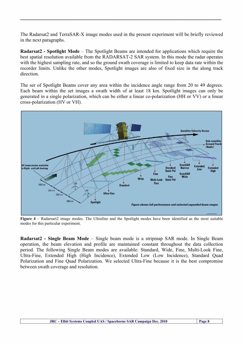
__________________________________________________________________________________
JRC ndash Elbit Systems Coupled UAS Spaceborne SAR Campaign Dec 2010 Page 8
The Radarsat2 and TerraSAR-X image modes used in the present experiment will be briefly reviewed in the next paragraphs Radarsat2 - Spotlight Mode ndash The Spotlight Beams are intended for applications which require the best spatial resolution available from the RADARSAT-2 SAR system In this mode the radar operates with the highest sampling rate and so the ground swath coverage is limited to keep data rate within the recorder limits Unlike the other modes Spotlight images are also of fixed size in the along track direction The ser of Spotlight Beams cover any area within the incidence angle range from 20 to 49 degrees Each beam within the set images a swath width of at least 18 km Spotlight images can only be generated in a single polarization which can be either a linear co-polarization (HH or VV) or a linear cross-polarization (HV or VH)
Figure 4 ndash Radarsart2 image modes The Ultrafine and the Spotlight modes have been identified as the most suitable modes for this particular experiment Radarsat2 - Single Beam Mode ndash Single beam mode is a stripmap SAR mode In Single Beam operation the beam elevation and profile are maintained constant throughout the data collection period The following Single Beam modes are available Standard Wide Fine Multi-Look Fine Ultra-Fine Extended High (High Incidence) Extended Low (Low Incidence) Standard Quad Polarization and Fine Quad Polarization We selected Ultra-Fine because it is the best compromise between swath coverage and resolution
__________________________________________________________________________________
JRC ndash Elbit Systems Coupled UAS Spaceborne SAR Campaign Dec 2010 Page 9
Radarsat2 - Ultra-Fine ndash The Ultra-Fine Resolution Beams are intended for applications which require very high spatial resolution In this mode the radar operates with the highest sampling rate and so the ground swath coverage is limited to keep data rate within the incidence angle from 20 to 49 degrees Each beam within the set images a swath width of at least 20 km Ultra-Fine Resolution images can only be generated in a single cross-polarization which can be either a linear co-polarization (HH or VV) or a linear cross-polarization (HV or VH) The standard TerraSAR-X operational mode is the single receive antenna mode from which the following imaging modes can be retrieved High Resolution Spotlight and Spotlight StripMap and ScanSAR The single receive antenna mode uses a chirp bandwidth of up to 300 MHz
Figure 5 ndash Radarsart2 image modes The Ultrafine and the Spotlight modes have been identified as the most suitable modes for this particular experiment The SpotLight (SL) imaging modes use phased array beam steering in azimuth direction to increase the illumination time ie the size of the synthetic aperture This leads to a restriction in the image scene size Thus the scene size is technically restricted to a defined size 10 km x 10 km for the SpotLight mode and 10 km x 5 km (width x length) in the HighResolution SpotLight (HS) mode This sophisticated imaging mode makes it possible to acquire data with up to 1 m resolution in the HighResolution SpotLight mode (acquired with a bandwidth of 300 MHz) and 2 m in the standard SpotLight mode StripMap (SM) is the basic SAR imaging mode as known eg from ERS-1 and other radar satellites The ground swath is illuminated with continuous sequence of pulses while the antenna beam is fixed in elevation and azimuth This results in an image strip with a continuous image quality (in flight direction) StripMap dual polarisation data have a slightly lower spatial resolution and smaller swath than the single polarisation data In StripMap mode a spatial resolution of up to 3 m can be achieved The standard scene size is 30 km x 50 m (width x length) in order to obtain manageable image files however acquisition length is extendable up to 1650 km
__________________________________________________________________________________
JRC ndash Elbit Systems Coupled UAS Spaceborne SAR Campaign Dec 2010 Page 10
33 ndash Partners Involved and their Roles The partners involved in this experiment comprised the European Commission (EC) ndash Joint Research Centre (JRC) and Elbit Systems from Haifa Israel The role of each partner is briefly described next 331 - European Commission (EC) ndash Joint Research Centre (JRC) ndash The main role of the EC-JRC was the planning set up execution and the analysis of the data together with Elbit Systems This comprised
a) the definition of the objectives b) the research methods used c) the ground truth data collection d) the analysis of the data and the conclusions of the experiment
332 ndash Elbit Systems ndash The main role of Elbit Systems comprised
a) the deployment and operation of the boat used as target b) the deployment and operation of the UAS Hermes 450 c) the contacts with the Israeli authorities namely the Israeli Air Force and Civil Aviation
Authority d) the collection of ground truth data e) The analysis of the data and conclusions of the experiment
__________________________________________________________________________________
JRC ndash Elbit Systems Coupled UAS Spaceborne SAR Campaign Dec 2010 Page 11
4 ndash Experiment Execution
41 ndash Modus Operandi The modus operandi of the trial was as follows 1- JRC supplied Elbit Systems with the footprint (frame) of the spaceborne SAR images to be acquired (TerraSAR-X-Stripmap and Radarsat-2 Spotlight) as well as the time of the SAR satellite passes 2- The boat was deployed about 2 nautical miles Southwest of the Port of Haifa The boat was about 12-meter long The boat had a crew of 3 people plus one JRC staff 3- The boat left from the port of Haifa and travelled a couple of nautical miles to reach the test site Once the test site was reached the boat was stationary at the time of the satellite SAR overpass After the satellite overpasses the boat was steered at different speeds to test the tracking capabilities of the UAV
42 ndash Ground Truth Data Collection The ground truth data collected comprised a) the sea state b) Data from the UAS sensors b) the weather conditions and wind speed e) Photos and movies of the boats involved in the experiment
43 ndash Means Involved in the Experiment The means involved in the experiment comprised two satellite SAR images namely a TerraSAR-X-Stripmap and a Radarsat-2 Spotlight and one 12-meter long boat 431 ndash Boat Deployed During the Experiment Figures 6 illustrate the boat deployed as target during the experiment
__________________________________________________________________________________
JRC ndash Elbit Systems Coupled UAS Spaceborne SAR Campaign Dec 2010 Page 12
Figure 6 ndash The 12-meter boat deployed during the experiment at the Port of Haifa Israel 432 ndash Hermes 450 ndash System Overview The Hermesreg UAV system is a mature and operationally proven system with accumulated experience with the Israel Defense Forces operations and with other users worldwide It features a fully redundant architecture leading to a high level of safety and reliability a high level of autonomy modern high performance state-of-the-art payloads and a small logistic footprint Figure 7 shows the main elements of the Hermes UAV System 433 ndash The Air Vehicle Hermesreg 450W is a modern UAV design featuring highly efficient aerodynamics composite structure and a high level of system redundancy and autonomy Its compact size and high maximumempty weight ratio enable very high mission effectiveness delivering potent payloads high endurance and a modest logistic footprint The Hermesreg 450 is in production and has accumulated over 150000 flight hours with the Israeli Air Force and other users around the globe The Hermesreg 450W uses the higher power delivered by the AR802W engine to achieve higher gross weight with the same platform greatly increasing payload and fuel carrying capability a shorter takeoff run and expanded flight envelope
__________________________________________________________________________________
JRC ndash Elbit Systems Coupled UAS Spaceborne SAR Campaign Dec 2010 Page 13
The AR802W engine is a derivative of the AR802 rotary engine with widened rotor and housing The result is a 30 gain in power to nearly 70HP Coupled to an Electronic Fuel Injection system the engine is highly efficient and has improved maintenance figures Following is a summary of the physical characteristics of the Hermes 450W air vehicle is given in Table 2
Table 2 ndash Summary of Hermes 450 main characteristics Physical Characteristics
bull Length 61 m bull Wingspan 105 m bull Fuselage diameter 0508 mm bull Max takeoff weight 550 kg bull Max internal fuel weight (including oil) 115 kg bull Max payload weight 150 kg
Figure 7 ndash Elements of the Hermes UAV System
434 ndash Ground Control Station (GCS) The GCS is a transportable system designed to perform and support all Hermesreg UAV family ground Based activities operational activities These activities include mission planning pre-flight check takeoff and landing UAV flight control mission control payloads and systems control as well as post-mission debriefing An embedded or appended training capability is optional Remote communication of video and telemetry to a C4I center via SATCOM or WAN infrastructure is optional The GCS provides a user friendly comfortable effective and protected environment for carrying out UAV missions
__________________________________________________________________________________
JRC ndash Elbit Systems Coupled UAS Spaceborne SAR Campaign Dec 2010 Page 14
The GCS is housed in a shelter with operator consoles of advanced human engineering design that provide an ergonomic operational environment The shelter is based on the NATO ACE III shelter with a side door As Israelrsquos leading C4I provider Elbit Systems has incorporated Hermesreg GCS advanced C4I capabilities including comprehensive mission planning tactical database management and tactical coordination with supported forces and command elements The Hermesreg GCS is uniquely capable of performing two UAV missions concurrently with two UAVs each of which is controlled via a separate Ground Datalink Terminal (GDT) The Hermesreg GCS requires minimal operating personnel ie mission commander and mission operator
Figure 8 ndash The UAS Hermes 450 Ground Control Station (GCS)
435 ndash The EO Payload The CoMPASS Compact Multi Purpose Advanced Stabilized System is a day and night surveillance system that includes a 3rd generation 3-5 μm zoom FLIR camera a color zoom TV CCD camera and automatic tracking capabilities The CoMPASS enables the following
bull Day and night stabilized LOS observation with capabilities of target detection recognition and identification in various weather conditions
bull Automatic and manual tracking of targets bull Slaving CoMPASS Line of Sight (LOS) to external systems bull LOS information bull Target Laser designationampRanging or only Target Laser Ranging bull Laser Target Marker
__________________________________________________________________________________
JRC ndash Elbit Systems Coupled UAS Spaceborne SAR Campaign Dec 2010 Page 15
CoMPASS the EOIR system for UAV applications is the most advanced payload version of the CoMPASS family featuring reduced weight high degree of modularity and flexibility space-saving packaging and advanced operational and video processing features The CoMPASS based STA Stabilized Turret Assembly is a single LRU housing
bull 3rd generation 3-5 μm FLIR zoom Camera bull Color Zoom TV CCD Camera bull Laser Target Designator bull Laser Target Marker bull Electronic Boards
Figure 9 ndash CoMPASS Stabilized Turret Assembly (STA)
__________________________________________________________________________________
JRC ndash Elbit Systems Coupled UAS Spaceborne SAR Campaign Dec 2010 Page 16
5 ndash Preliminary Data Analysis
51 ndash SAR Satellite Imagery Processing The high resolution spaceborne SAR image was analysed visually because the resolution is good enough to allow visual analysis and the site is too close to the coast which makes automatic processing more difficult and prone to error due to artefacts caused by land targets The Hermes 450 images were also analysed visually
52 ndash Ground Truth Data This section briefly describes the Ground Truth data namely the GPS positions of the boat deployed as target during the experiment a photo of the boat as well as other relevant ground truth data collected
521 ndash GPS coordinates of the boat deployed Table 5 gives the GPS coordinates of the boat deployed during the experiment at the time of the Radarsat-2 satellite overpass Table 3 ndash Ground Truth data collected at the time of the satellite pass (154740 UTC=174740 LT) on 8 December 2010
Date 8 Dec2010 Time 154740 UTC=174740 LT Pass Ascending
SatelliteMode Radarsat-2 Spotlight Polarisation HH
Boats Type Size Latitude Longitude
Elbits 12-meter
Boat
32˚ 51830 N 32deg514980N 32863833deg N
34˚ 57961 E 34deg575766E 34966017deg E
__________________________________________________________________________________
JRC ndash Elbit Systems Coupled UAS Spaceborne SAR Campaign Dec 2010 Page 17
521 ndash HERMES 450 Ground Truth Data Table 4 shows the 12-meter Elbitacutes Boat as detected by the IR sensor of the Hermes 450 Table 4 ndash Hermes 450 Ground Truth Data Date 8 Dec2010 Time 154740 UTC=174740 LT
Platform Hermes 450
UAV Type Size Latitude Longitude
UAV Hermes
450
174730h 3284489947 N
174800h
3285089687 N
174730h 3498564048 E
174800h
3499338667 E
Elbits 12-meter
Boat UAV
Image
32˚ 51830 N 32deg514980N 32863833deg N
34˚ 57961 E 34deg575766E 34966017deg E
53 ndash Weather Conditions and Sea State The weather conditions in Haifa are summarized in Table 5 bellow
Table 5 ndash Wind speed wind direction and Temperature Time (IST) Temp Dew
Point Humidity Pressure Visibility Wind Dir
Wind Speed
Gust Speed Precip Events Conditions
550 PM 210 degC 130 degC 60 1017 hPa - North 111 kmh
31 ms - NA Clear
__________________________________________________________________________________
JRC ndash Elbit Systems Coupled UAS Spaceborne SAR Campaign Dec 2010 Page 18
Figure 10 gives the weather data (Temperature Barometric Pressure Wind Speed and Wind Direction) for Haifa Israel on 8 Dec 2010
Figure 10 ndash Weather data (Temperature Barometric Pressure Wind Speed and Wind Direction) for Haifa Israel on 8 Dec 2010
__________________________________________________________________________________
JRC ndash Elbit Systems Coupled UAS Spaceborne SAR Campaign Dec 2010 Page 19
54 ndash Verification of the Results This section briefly describes the verification of the targets detected in the spaceborne SAR image and in the Hermes 450 UAV using the ground truth data collected during the experiment
541 ndash Overview of the UAV Trajectory and the SAR Imagery Footprint Figure 11 gives an overview of the UAV trajectory the footprint of the SAR imagery and the area of the experiment near the port of Haifa The UAV trajectory is depicted in blue The large red rectangle is the footprint of the TerraSAR-X Stripmap The smaller red rectangle is the footprint of the Radarsat-2 Spotlight image
Figure 11 ndash Google Earth UAV trajectory during the experiment and footprinst of the SAR imagery ordered for the experiment Figure 12 is a zoom in of the previous image which allows a more detailed view of the UAV trajectory and of the port of Haifa Figure 13 is a zoom in of figure 12 It shows in more detail the UAV trajectory during the entire experiment and the port of Haifa in Israel
__________________________________________________________________________________
Figure 12 ndash Zoom in of the previous figure showing a more detailed view of the UAV trajectory and of the port of Haifa in Israel
Figure 13 ndash Zoom in of the previous figure showing a even more detailed view of the UAV trajectory and of the port of Haifa in Israel
JRC ndash Elbit Systems Coupled UAS Spaceborne SAR Campaign Dec 2010 Page 20
__________________________________________________________________________________
JRC ndash Elbit Systems Coupled UAS Spaceborne SAR Campaign Dec 2010 Page 21
542 ndash Targets Detected in the Radarsat-2 Spotlight Image Figure 14 illustrates the position of the Elbitrsquos boat used as target in the experiment at the approximate time of the SAR Satellite pass by 1547 UTC (1747 LT) The small photo of the boat shows the approximate position of the boat The two small planes show the positions of the UAV immediately before and after the SAR Satellite pass
Figure 14 ndash Google Earth positions of the elbitrsquos boat and the UAV (Hermes450) at the approximate time of the SAR Satellite overpass by 174740 UTC Figure 15 shows the corresponding SAR image (Radarsat-2 Spotlight) acquired during the experiment Pins 1 and 2 represent the positions of the UAV before and after the SAR satellite overpass Pin 3 illustrates the position of the Elbitacutes boat deployed at the time of the satellite overpass At this scale the SAR signature of the boat is not distinguishable from the sea clutter background However zooming in the SAR image the SAR signature can clearly be seen as illustrated in figure 12 The SAR image in figure 12 also shows several SAR signatures of large ships in the area at the time of the satellite overpass
__________________________________________________________________________________
JRC ndash Elbit Systems Coupled UAS Spaceborne SAR Campaign Dec 2010 Page 22
Elbit`s Boat
Figure 15 ndash On the background the SAR image with the two UAV positions before and after the satellite overpass (Pin1 and Pin2) and the Elbitacutes Boat position (Pin3) The small window over the SAR image shows a zoom in of the SAR image where the SAR signature of the Elbitacutes Boat can clearly be seen The top right are of the SAR image also shows SAR signatures of several large ships in the area at the time of the SAR satellite overpass Figure 16 shows the corresponding SAR image (Radarsat-2 Spotlight) acquired during the experiment and the UAV IR images of some of the targets Pins 1 and 2 represent the positions of the UAV before and after the SAR satellite overpass Pin 3 illustrates the position of the Elbitacutes boat deployed at the time of the satellite overpass At this scale the SAR signature of the boat is not distinguishable from the sea clutter background However zooming in the SAR image the SAR signature can clearly be seen as illustrated in figure 13 On the top left the UAV IR image of the Elbitrsquos Boat The SAR image in figure 13 also shows several SAR signatures of large ships in the area at the time of the satellite overpass On the centre left the UAV IR image of a large ship On the centre right the UAV IR image of a large ship On the bottom right the UAV IR image of a large ship All the UAV images were acquired at night in complete darkness from altitudes in the order of 5500 meters Nonetheless the quality and detail of the UAV images allows classification of the targets and in some cases the identification As it can be seen the potential of UAV for maritime surveillance is very promising During the experiment the UAV detected all the boats and ships in the area and tracked some of the boatsships to test the tracking capability The capability of detection and tracking targets is a critical capability for maritime surveillance
__________________________________________________________________________________
JRC ndash Elbit Systems Coupled UAS Spaceborne SAR Campaign Dec 2010 Page 23
Elbitacutes Boat
Elbit`s Boat
Figure 16 ndash Zoom-in of figure 15 with the UAV images of some targets On the top left the UAV IR image of the Elbitrsquos Boat On the centre left the UAV IR image of a large ship On the centre right the UAV IR image of a large ship On the bottom right the UAV IR image of a large ship Figure 17 shows a comparison of the SAR and UAV images with an optical photo taken in Haifa Israel a couple of hours before the SAR satellites overpass Most of the large ships were detected in the SAR image and some of these ships can be identified in the optical photo Some of the ships in the photo left the area before the SAR satellites overpass
__________________________________________________________________________________
JRC ndash Elbit Systems Coupled UAS Spaceborne SAR Campaign Dec 2010 Page 24
Figure 17 ndash Photo taken in Haifa Israel a couple of hours before the SAR satellites overpass This phot shows the large ships moored in the area Most of these large ships were detected in the Radarsat-2 image As expected their positions and orientations were slightly different at the time of the satellite overpass
Elbitacutes Boat
Elbit`s Boat
__________________________________________________________________________________
JRC ndash Elbit Systems Coupled UAS Spaceborne SAR Campaign Dec 2010 Page 25
Figure 18 ndash Photo taken in Haifa Israel a couple of hours before the SAR satellites overpass This phot shows the large ships moored in the area Most of these large ships were detected in the Radarsat-2 image As expected their positions and orientations were slightly different at the time of the satellite overpass Figure 18 illustrates the SAR image and the corresponding google earth image of a small pier in the port of Haifa In the SAR image due to several artefacts it is not possible to detect the 7 small boats moored to the small pier The UAR IR image of the same area clearly shows the 7 small boats with impressive detail taking into account that the image was acquired from an altitude of about 5500 meters A zoom in of the same UAV IR image is shown in figure 19 As it can be seen although the image was acquired from an altitude of about 5500 meters the 7 small boats can be clearly seen with enough detail to allow classification of the type of boat A UAV flight at lower altitude would probably giver a lot more detail and eventually allow the identification of the small boats
__________________________________________________________________________________
JRC ndash Elbit Systems Coupled UAS Spaceborne SAR Campaign Dec 2010 Page 26
Figure 19 ndash UAV IR image of a small pier in the port of Haifa Israel where 7 small boats can be seen with enough detail to allow classification This image was acquired from an altitude of about 5500 meters in the dark
__________________________________________________________________________________
55 ndash Quantitative Analysis of the Spaceborne SAR Image In order to allow a quantitative analysis of the data the spaceborne SAR image was calibrated using ESArsquos NEST software package version 4B The input was the SAR image acquired and the output was the Radiometric Calibration (Sigma Naught (σdeg)) expressed in terms of intensity and in decibel (dB) the Radar Brightness (βdeg) and the Radiometric Normalisation (gamma naught (γdeg))
551 ndash Radarsat-2-Spotlight 08Dec2010 (154740 UTC) Haifa Israel Figure 20 illustrates the Intensity band of a subset of the Radarsat-2Spotlgiht image (08Dec2010)
Figure 20 ndash Radarsat-2 Spotlgiht image (08Dec2010) ndash Sigma Naught (Intensity) band
JRC ndash Elbit Systems Coupled UAS Spaceborne SAR Campaign Dec 2010 Page 27
__________________________________________________________________________________
Figure 21 illustrates the Sigma Naught Coefficient of the Radarsat-2 Spotlgiht image (08Dec2010) expressed in terms of intensity and decibel (dB)
Figure 21 ndash Radarsat-2 Spotlgiht image (08Dec2010) - On the left the Sigma Naught (σdeg) (intensity) and on the right the Sigma Naught (σdeg) (dB)
ormalisation amma Naught (γdeg)) of the Radarsat-2 Spotlgiht image (08Dec2010) expressed in dB
-2 Spotlgiht image (08Dec2010) - On the left the Beta Naught (βdeg) and on the right the Gamma Naught (γdeg) (dB)
Figure 22 illustrates the Radar Brightness (Beta Naught (βdeg)) and the radiometric n(G
Figure 22 ndash Radarsat
JRC ndash Elbit Systems Coupled UAS Spaceborne SAR Campaign Dec 2010 Page 28
__________________________________________________________________________________ Figure 23 shows the Sigma Naught (σdeg) in dB after some colour manipulation and the histogram of the Sigma Naught (σdeg) image
Figure 23 ndash Radarsat-2 Spotlgiht image (08Dec2010) - On the top left the Sigma Naught (σdeg) after colour manipulation to enhance the targets and on the top right the corresponding histogram On the bottom we can see the histogram of the image
Table 6 gives the statistics of the Sigma Naught (σdeg) Radarsat-2 Spotlgiht image (08Dec2010) The Sigma Naught (σdeg) range from -72897 dB up to 23465 dB The Mean value is -16855 dB the Median is -16594 dB and the standard deviation is 7077 dB
JRC ndash Elbit Systems Coupled UAS Spaceborne SAR Campaign Dec 2010 Page 29
__________________________________________________________________________________
JRC ndash Elbit Systems Coupled UAS Spaceborne SAR Campaign Dec 2010 Page 30
Table 6 ndash Statistics of the Radarsat-2 Spotlgiht image (08Dec2010) (154740 UTC)
Statistics Values Unit Only ROI-Mask pixels considered Number of pixels total Number of considered pixels Ratio of considered pixels
No 322394283 322394283
1000
Minimum Maximum
-728974609375 234655818939209
intensity_db intensity_db
Mean Median Std-Dev Coefficient of Variation
-16855686580177853 -1659462338617847 707796800831575
07888765273432338
intensity_db intensity_db intensity_db intensity_db
Checking the radar backscattering coefficient of some targets (small boat and some large ships) detected in the Radarsat-2 Spotlight image we get values ranging from -0379 dB up to 23455 dB The analysis of the Sigma Naught values (σdeg) of the targets and the area around the targets shows a significant contrast
56 ndash Summary of the Preliminary Analysis of the Spaceborne SAR Image This experiment involved two spaceborne SAR images namely a TerraSAR-X Stripmap and one Radarsat-2 Spotlight The TerraSAR-X image was not delivered by DLR due to technical problems The Elbitrsquos boat deployed during the experiment was detected in the Radarsat-2 Spotlight image Several other targets including a set of large ships were also detected Table 7 summarises the characteristics of the SAR image acquired and the targets detected
Table 7 ndash List of SAR Satellite Images acquired during the experiment and detected boats ISRAEL (HAIFA)
Date Time Place Satellite Mode Ground Truth Data Detected Boats
08Dec2010 (PM) Haifa - Israel Radarsat-2 Spotlight GPSPhotosMovies 1 small boat deployed + 9 large ships
Table 8 gives the minimum and maximum Sigma Naught (σdeg) of the targets detected in each SAR image
Table 8 ndash Minimum and maximum Sigma Naught (σdeg) of the targets detected in each SAR image
Date Time UTC (LT)Pass Satellite Image Mode Polarisation Sigma Naught (σdeg) Min Max
29Oct2010528UTC(728AM LT) DES Radarsat-2 Spotlight HH --0379 dB 23455 dB The SAR signatures of the boats deployed were very weak Some possible reasons to explain such weak signatures are the sea state the wind speed the incidence angle and the type and materials Another possible reason is the processing at DLR
__________________________________________________________________________________
JRC ndash Elbit Systems Coupled UAS Spaceborne SAR Campaign Dec 2010 Page 31
6 ndash Preliminary Conclusions The analysis of the results of this coupled UASSpaceborne SAR experiment shows a promising potential for the use of UAS for maritime surveillance UAS can be integrated into the airborne building block of maritime surveillance systems to complement the existing assets increase system performance and improve the overall maritime domain awareness The main perceived maritime security and safety threats comprise piracy terrorist and military threats weapons proliferationsmuggling drugs trafficking illegal immigration unlawful use of containers attacks to critical infrastructures and illegal fishing The main maritime security and safety gaps include a lack of technologies with the capability of detecting small targets (eg small boats) a lack of wide area and persistent maritime surveillance a lack of coordination and information sharing limited interoperability a lack of containers security a lack of persistent surveillance of critical infrastructures and early warning systems Unmanned Aircraft Systems (UAS) are an emerging technology with strong potential to mitigate the above mentioned threats by filing in the main maritime security and safety gaps listed earlier For instance the wide range of potential applications of UAS to maritime surveillance includes but is not limited to
bull detection classification and identification of small boats bull persistent maritime surveillance bull use as communications relays bull persistent surveillance of critical infrastructures bull early warning systems bull COMINT and ELINT collection etc
Table 11 illustrates the mapping of maritime securitysafety threats vs gaps and summarises the main potential applications of UAS to maritime surveillance The above mentioned potential applications of UAS to the Maritime Domain will be addressed in turn in more detail next bull Detection classification and identification of small boats ndash The capability of detecting classifying and identifying small targets (eg small boats) is among the key technologies required to improve maritime domain awareness This capability is critical to mitigate piracy illegal immigration drugs trafficking weapons smuggling illegal fishing terrorism and critical infrastructure Unmanned Aircraft Systems (UAS) provide this capability more efficiently and at a lower cost than any other existing technology bull Persistent maritime surveillance ndash With the continuous improvements of UAS technologies such as platforms sensors collision avoidance systems command and control systems telecommunications etc UAS are increasing their autonomy endurance and flexibility These characteristics are very important for persistent maritime surveillance UAS can be launched from land ships aircraft and technologies to launch UAS from submarines are currently under development UAS have distinct advantages over other existing technologies for persistent maritime surveillance in terms of autonomyendurance (the Global Surveyor has an autonomy of 1 week) cost (eg as the autonomy of UAS increases the number of staff required to operate UAS decreases) risk (eg if the UAS crashes the crew is not at risk) flexibility (eg they can be launched from a ship reducing the time to reach potential threats) etc
__________________________________________________________________________________
JRC ndash Elbit Systems Coupled UAS Spaceborne SAR Campaign Dec 2010 Page 32
bull Communications relays ndash UAS are being used as communication relays mainly in military context but have the potential to play a similar role in Civil context in several situations such as to replace satellite communications or as a redundant system over any location on Earth The main advantages of using UAS as communication relays is that airborne communication relays mitigate kinetic and noise jamming threats to satellite communications uplinks by providing an alternative set of links either directly to surface-based terminals or to satellites beyond the range of threats They are less susceptible to noise jamming threats than satellites because an adversary has to detect geolocate and track the airborne asset and operate within line of sight of the receive antenna main beam bull Persistent surveillance of critical infrastructures ndash The security of critical infrastructures such as nuclear power plants refineries ports etc requires persistent surveillance UAS can play an important role in providing persistent surveillance over critical infrastructures and over a wide area around the critical infrastructure Some advantages of UAS over other existing technologies such as ground-based assets (eg video cameras alarm systems manned aircraft etc) comprise the security of the UAS (eg hardly can be damaged or switched off as any ground-based asset) the area covered by a UAS (eg it is larger than the area covered by any ground-based asset) the cost (eg UAS is cheaper than manned aircraft with similar capability) etc bull Early warning systems ndash UAS have the potential to be used as part of an integrated system of systems for early warning A UAS can provide information about a given area at a fraction of the cost of alternative means Formation flying of UAS can cover a wide maritime area It is reasonable to assume that in a foreseeable future with the advent of UAS with increased autonomy the operations cost of UAS will likely decrease making them increasingly more attractive bull COMINT and ELINT collection ndash SIGNal INTelligence (SIGNINT) can be divided into two categories namely COMINT and ELINT COMINT stands for Communication Intelligence and ELINT for Electronic Intelligence Collection of COMINT is passive Exploitation of COMINT requires a human operator which implies COMINT UAS are suitable for COMINT and ELINT collection in different scenarios The relatively reduced amount of data collected and analysed during this experiment and the lessons learned do not allow drawing final conclusions about the feasibility of using Unmanned Aerial Systems (UAS) for maritime surveillance However this experiment allowed hands-on experience with UAS technologies and significantly improved the awareness for its applications to maritime surveillance and related issues involved including its potential the feasibility as well as the limiting and enabling factors These different aspects will now be analysed in turn in the next sections Table 11 illustrates the mapping of the main maritime security threats and gaps as well as the main priorities in terms of the different technologies involved in maritime surveillance For each maritime threat the technologies required to fill in each gap is indicated and its priority is expressed in a range of numbers (1 to 3 1 = Maximum Priority 2 = Medium Priority 3 = Low Priority) and colours (Red = Maximum Priority Orange = Medium Priority Green = Low Priority) The main technologies involved in maritime surveillance are listed on the bottom of figure 4 and are reproduced here for convenience of the reader 1- Reporting Systems 2- Sensors 3- Platforms 4- Communications 5- Data Fusion amp Sharing 6- Intelligence and 7- Databases For example the mitigation of the main threat Piracy requires filling in several maritime security gaps (eg lack of persistent surveillance lack of wide-are maritime surveillance lack of small boat detection lack of Early Warning Systems and lack of Information Sharing with maximum priority (1- Red) and among the required technologies listed are UAS LTAAV GEO-HR etc Concerning the remaining two gaps (Limited Interoperability and Containers Security) they are less relevant to mitigate Piracy hence the priority for Limited Interoperability is 2-Orange and for Containers Security is 3- Green
__________________________________________________________________________________ Table 9 ndash The Main Maritime Security and Safety Threats vs Gaps and the technologies that can be used to mitigate them
Maritime Security Main Threats GapsGapsrarr
darrThreats
Lack o f Risk As sessmentCapab ility
La ck of Persiste nt
Surveilla nce
La ck of Wid e-Area su rve illanc e
La ck of Small Boat De tecti on
Lack o f Earl y Warn ing Sys tems
L ack of In forma tion
Sh arin g
L imi ted In terop era bility
Lac k of Co ntai ners
Se cur ity
bull PiracyUAS LTAVG EO-
HR + UAS LT AVGEO-
HR + SAR GEO-HR
+ UAS USV LTAV
+ UAS LTAV
+ Coord in ationamp Sharing +
Inter opera bilityOptimisation +
1 2 3 5 6 7 1 2 3 5 6 7 1 2 3 5 6 1 2 3 123456 4567 1234567 1234567
bull Terro rismUAS LTAVG EO-
HR + UAS L TAV GEO-HR +
SAR AISGEO-HR +
UAS USV LTAV+
Intelligence+
Inte lligen ce+
Inter opera bilityOptimisation +
Intelligence+
1 2 3 5 6 7 1 2 3 5 6 1 2 3 5 6 1 2 3 123456 4567 1234567 1234567
bull Wea pon s ofM ass Dest ru ctio n Smugg ling
UAS LTAVG EO-HR +
UAS LT AVGEO-HR +
SAR AIS+
UAS USV LTAV+
Intelligence+
Inte lligen ce+
Intelligence+
Intelligence+
1 2 3 5 6 7 1 2 3 5 6 1 2 3 5 6 1 2 3 123456 4567 1234567 1234567
bull Drug sTraffic king
UAS LTAVG EO-HR +
UAS LT AVGEO-HR +
SAR AIS+
UAS USV LTAV+
Intelligence+
Inte lligen ce+
Intelligence+
Intelligence+
1 2 3 5 6 7 1 2 3 5 6 1 2 3 5 6 1 2 3 123456 4567 1234567 1234567
bull Illega lImmigratio n
UAS LTAVG EO-HR +
UAS LT AVGEO-HR +
SAR AIS+
UAS USV LTAV+
Intelligence+
Inte lligen ce+
Intelligence+
Intelligence+
1 2 3 5 6 7 1 2 3 5 6 1 2 3 5 6 1 2 3 123456 4567 1234567 1234567
bull Critic alI nfrastruc tureSecu rit y
UAS LTAVG EO-HR +
UAS LT AVGEO-HR +
SAR AIS+
UAS USV LTAV+ + Inte lligen ce
+ Intelligence
+ Intelligence
+
1 2 3 5 6 7 1 2 3 6 1 2 3 5 6 1 2 3 123456 4567 1234567 1234567
bull Illega lFish ing
UAS LTAVG EO-HR +
AI S+SAR UASLTAV +
SAR AIS GEO-HR+
UAS USV LTAV+
Intelligence+
Inte lligen ce+
Intelligence+
1 2 3 5 6 7 1 2 3 5 7 1 2 3 5 6 1 2 3 123456 4567 1234567
bull Un lawf ul Use of Co nta iners
(Secur ity)
UAS LTAVG EO-HR +
GPS Tr acking+
Intelligence+
Inte lligen ce+
GPS Int rusion Det ection Se al
1 2 3 5 6 7 4 6 7 1 2 3 5 6 1 2 3 123456 4567 1234567 1234567
(-) Priority (+) Not Rel evant
SURVEILLANCETECHNOLOGIES
1- Reporti ng Systems
2 -Sensors 3 -P latforms 4 - Communications 5- Data Fusionamp Sharing
6 -I ntelli gence 7 -Databases
JRC ndash Elbit Systems Coupled UAS Spaceborne SAR Campaign Dec 2010 Page 33
__________________________________________________________________________________
JRC ndash Elbit Systems Coupled UAS Spaceborne SAR Campaign Dec 2010 Page 34
61 ndash Hands-on experience with UAS technologies and its applications to maritime surveillance This coupled UASSpaceborne SAR campaign was a unique opportunity to acquire further handsndashon experience with UAS technologies and learn about the main issues related to its applications to maritime surveillance From the planning phase up to the execution of the UAS flight and landing there are several factors that need to be carefully analysed and taken into account A summary of the main issues identified in this experiment is given next 1- Selection of the Experiment Area Authorisation to Fly ndash For the time being UAS can only be flown in restricted areas usually under control of national authorities often the military This is due to the risks that a UAS can pose to human life and property In the present case an area under the authority of the Israeli Civil Aviation Authority was selected The authorisation to fly was not easy to obtain because the selected area is under the authority of the Civil Aviation Authority Figure 24 indicates the area of the experiment in Haifa Israel 2- UAS Communications Issues ndash The Hermes 450 was flown in Line-of-Sight (LOS) since it was close to the coast For BLOS (Beyond Line-of-Sight) operation satellite communications are required 3- Synthetic Aperture Radar (SAR) ndash The specific model Hermes 450W used in the experiment had no SAR sensor installed However a SAR sensor can be installed A SAR sensor is important for maritime surveillance since it allows 247 operations regardless of the weather conditions 4- Automatic Identification System (AIS) Receiver ndash The Hermes 450 used in this experiment was not equipped with an AIS receiver For maritime surveillance operations an AIS receiver is a very important tool since it allows the automatic identification of most ships allowing the UAS to concentrate on non-identified ships
__________________________________________________________________________________
Figure 24 ndash The area of the experiment is indicated by the GPS Trajectory of the UAV
62 ndash Potential of UAS for Maritime Surveillance UAS technologies are relatively recent and involve a wide range of fields spanning from aeronautics and sensors technologies to satellite communications and other engineering disciplines Innovations in each of the fields involved are emerging by the day UAS still have a long way to go before they become mature and their use fully operational For the time being UAS are mainly used for military applications However a large number of non-military UAS applications have been identified by stakeholders and there are several studies and demonstration flights foreseen for the near future Maritime surveillance is one of the most challenging and promising fields of application of UAS The challenges are due to the very demanding conditions under which the UAS must operate over sea and the requirements for safe operation
JRC ndash Elbit Systems Coupled UAS Spaceborne SAR Campaign Dec 2010 Page 35
__________________________________________________________________________________
JRC ndash Elbit Systems Coupled UAS Spaceborne SAR Campaign Dec 2010 Page 36
The present UAS experiment has unveiled some of the potential of UAS for maritime surveillance The UAS tests performed during this experiment include
1 ndash Detection of a Small rubber Boat and a Fishing Ship 2 ndash Tracking of a Small Boat and a Fishing Ship 3 ndash Classification of a Small Boat and a Fishing Ship 4 ndash Identification of a Small Boat and a Fishing Ship 5 ndash Detection and Tracking of People on the Beach
Despite the operational requirement that prevented the UAS from flying bellow 3km the experiment has confirmed the capability of UAS for small boat detection tracking and classification as well as the capability for people detection and tracking Concerning the identification of the targets the characteristics of the images acquired during this mission suggest that flying at lower altitudes the UAS images would allow the identification of the targets The UAS images can be seen from Figure 15 to 20
621 ndash Advantages of UAS for maritime Surveillance Some of the advantages of using UAS for maritime surveillance have been described in the literature and are summarized bellow
1- One potential benefit of UAS is that they could fill in a gap in current maritime surveillance by improving coverage
2- The range of UAS is a significant asset when compared to border agents on patrol or stationary surveillance equipment
3- Eletro-Optical InfraRed (EOIR) sensors (cameras) can identify small size objects from very high altitudes (high resolution)
4- UAS can provide precise and near-real-time imagery to a ground control operator who would then disseminate that information so that informed decisions regarding the deployment of border patrol agents can be made quickly
5- Long endurance UAS used along the border can fly for more than 30 hours up to several days without having to refuel compared with manned helicopterrsquos average flight time of just over 2 hours
6- The ability of UAS to loiter for prolonged periods of time has important operational advantages over manned aircraft
7- The longer flight times of UAS means that sustained coverage over a previously exposed area may improve maritime security
8- The range of UAVs is a significant asset when compared to border agents on patrol or stationary surveillance equipment Nevertheless the extended range and endurance of UAVs may lessen the burdens on human resources at the borders
9- UAS accidents do not risk the lives of pilots as do the helicopters and aircraft currently used by Coast Guards for border patrolling
__________________________________________________________________________________
JRC ndash Elbit Systems Coupled UAS Spaceborne SAR Campaign Dec 2010 Page 37
622 ndash Possible Drawbacks of using UAS for maritime Surveillance UAS also have disadvantages some of them are briefly described next
1- There have been concerns regarding the high accident rate of UAS which can be multiple times higher than that of manned aircraft Because UAS technology is still evolving there is less redundancy built into the operating system of UAS than of manned aircraft and until redundant systems are perfected mishap rates are expected to remain high
2- If control systems fail in a manned aircraft a well-trained pilot is better positioned to find the source of the problem because of hisher physical proximity If a UAS encountered a similar system failure or if a UAS landing was attempted during difficult weather conditions the ground control pilot would be at a disadvantage because he or she is removed from the event Unlike a manned pilot the remote pilot would not be able to assess important sensory information such as wind speed
3- Inclement weather conditions can also impinge on a UAS surveillance capability especially UAS equipped with only an EO camera and Forward Looking Infrared Radar (FLIR) because cloudy conditions and high humidity climates can distort the imagery produced by EO and FLIR equipment The effects of extreme climatic or atmospheric conditions on sensors reportedly can be mitigated with the outfit of one synthetic aperture radar (SAR) system and a moving target indicator (MTI) radar However adding SAR and MTI to a UAS platform would increase the costs associated with using UAS
4- Depending on the type of UAS the costs of operating a UAS can be higher than the costs of operating a manned aircraft This is because some types of UAS require a significant amount of logistical support and specialized operator and maintenance training Operating one UAS may require a crew of up to 20 support personnel The high comparative costs of operating some sophisticated types of UAS may be offset somewhat by their comparatively lower unit costs
63 ndash Main Limiting Factors Preventing the Use of UAS Several pre-requisites must be satisfied to render the UAS a viable cost-effective and regulated alternative to existing resources Major civil and commercial market barriers include
Single European Sky Sense and Avoid technologies Command and Control Technologies Reliability Communications (Bandwidth LOS BLOS)
Lack of airspace regulation that covers all types of UAV systems (encompassing lsquosense and avoidrsquo airspace integration and airworthiness issues)
Affordability - price and customization issues (eg commercial off-the-shelf open modular architecture) Lack of efforts to establish joint customer requirements (although this is gradually changing) Liability for civil operation Capacity for payload flexibility Lack of sufficient secure non-military frequencies for civil operation Perceived reliability (eg vehicle attrition rate vs manned aircraft) Operator training issues Recognitioncustomer perception of the UAV market Technology developments for multi-mission capability
__________________________________________________________________________________
64 ndash UAS Key Enabling Technologies Figure 25 illustrates the components of a typical UAV System showing some of the capabilities needed and the enabling technologies required for performing a given mission Any UAV mission involves many capabilities and technologies Due to the depicted system complexity the main key players such as the US Department of Defense (DoD) and other agencies have started to use the term Unmanned Aerial System (UAS) in place of UAV
Figure 25 ndash Unmanned Aerial Vehicle System Enabled by Autonomous Mission Management Reliable Flight Systems Navigation Accurate Systems Terrain Avoidance Power and Propulsion Some UAS key enabling technologies are listed below
Autonomous Mission Management Collision Avoidance Intelligent System Health Monitoring
Reliable Flight Systems Sophisticated Contingency Management Intelligent Data Handling and Processing Over-the-Horizon Communication Network-Centric Communication Open Architecture Power and Propulsion Navigation Accurate System Technology Enhanced Structures
JRC ndash Elbit Systems Coupled UAS Spaceborne SAR Campaign Dec 2010 Page 38
__________________________________________________________________________________
JRC ndash Elbit Systems Coupled UAS Spaceborne SAR Campaign Dec 2010 Page 39
Table 12 gives a more detailed description of other critical technologies for emerging autonomous UAV systems both civil and military Most of the technologies mentioned in Table 12 apply both to civil and military UAV systems Table 10 ndash Key Enabling Technologies (from SG75 study on autonomous systems)
Critical Technologies Decision Making Software
bull Fuzzy-based decision making bull Knowledge-based system bull Case-based reasoning bull Self-learning techniques bull Decision tree evaluation bull ReasoningInferring bull Probabilisticstochastic reasoning
Prediction Algorithms bull Predictive pathintent algorithms bull Short reaction algorithm bull Effectiveness evaluation
Status Assessment Software bull Internal status analysis bull Self-orientation
Situation Analysis Software bull Situation analysis bull Environmental analysis bull External status analysis
Modelling Software bull Air vehicle modelling algorithms bull Sensor modelling algorithms bull Scenario generation bull Threat system modeling bull Attack simulation bull Mission success optimisation model bull Simulation
Sensor Processing Software bull Sensor fusion bull Area of interest identification bull Automatic target recognition
Adaptive and Self-learning Systems bull Failure self-compensation
Attack Planning Software bull Attack plans and tactical alternatives bull Plan change impact identification
Weapon Engagement Procedure Software bull Weapon engagement algorithms
Mission Plan Update Software bull Route planning system bull Payload plan management system bull Mission Success Optimisation model
Path Optimisation Software bull Optimal trajectory planning bull Path Optimisation System
Targeting Software bull Target tracking bull Target prioritisation
Platform Technologies bull Obstacle detection and avoidance (airborne) bull Obstacle detection and avoidance (ground) bull Improved autopilot bull Speech recognition
Figure 26 summarises system element designs needed to transition from current to next-generation autonomous UAV systems for civilian and military UAS
__________________________________________________________________________________
Figure 26 ndash System Element Designs Needed to Transition from Current to Next-Generation Autonomous UAV Systems These new paradigms are a combination of system attributes and technological capabilities For instance the data fusion secure anti-jam and coordinated multi-vehicle control require technological development as well as specific system development to bring full maturity to unmanned systems Finally very small Micro UAVs (MAVs) and relatively large sophisticated UCAV systems are examples of the range of UAVs that are applying the new platforms payloads onboard processing communications etc to create next generation automated UAVs It is with these new platforms payloads etc that both UCAVs and MAV will be able to address similar operational challenges including
Mixed operation with other assets bull Deconfliction collision avoidance C4I integration
Operation over populated areas bull Safety issues Need to reduce reliance on communications bull UCAV ndash countermeasures bull MAV ndash limited size and power bull Limited line of sight environment Need a fully integrated system bull MAV propulsionpower generation still critical bull Operator machine interface critical bull All weather operations bull Survivability
JRC ndash Elbit Systems Coupled UAS Spaceborne SAR Campaign Dec 2010 Page 40
__________________________________________________________________________________
JRC ndash Elbit Systems Coupled UAS Spaceborne SAR Campaign Dec 2010 Page 41
65 ndash Mission Readiness
651 ndash Mission Readiness Summary This section summarises civil UAV mission readiness The purpose of Mission Readiness is to assess the readiness status of the different technologies involved in UAS In the present case this civil UAV mission readiness based on technology maturation forecasts that meet or exceed the desired or required capabilities identified by the user community Figure 27 summarises the mission readiness time forecasts for the different technologies The technologies annotated with an asterisk () are shown within the figure with maturation forecasts based on development targets expressed in the US Department of Defencesrsquo UAV Roadmap document The purpose of the chart is to be able to identify when the capability to fly a particular mission can be expected as a function of time The left-most end is the least probable and the right end the most probable timeframe
Figure 27 ndash Technology Maturation Summaries in Terms of Mission-Derived Capabilities
__________________________________________________________________________________
JRC ndash Elbit Systems Coupled UAS Spaceborne SAR Campaign Dec 2010 Page 42
66 ndash Small Boat Detection in SAR Satellite Imagery The use of spaceborne SAR imagery for small boat detection requires additional small boat detection experiments under different conditions using different methods It is not possible to draw final conclusions based on a limited number of small boat detection experiments which are not representative of the multiple possible scenarios
67 ndash Limitations of current State-of-the-Art SAR Satellite technology The main limitations of current State-of-the-Art spaceborne SAR imagery for maritime surveillance in particular aimed at small boat detection are 1 - SAR satellites repeat cycles do not allow the coverage of the same area at the required time intervals Constellations of SAR satellites could be a solution 2 - The conflict between resolution and image swath High resolution is required to detect small boats However the high resolution images have small swaths Maritime surveillance with high resolution images would require a large number of images to cover wide maritime areas which is very expensive and for the time being technically not feasible Intelligence data can play an important role by indicating an approximate position of suspicious non cooperative targets therefore reducing the surveillance area which can then be imaged using high resolution images 3- Spaceborne high resolution SAR imagery acquisition times are long enough to allow significant motion of the target during the acquisition time degrading the quality of the image Further research efforts are needed to develop new sensors and platforms As far as sensors are concerned shorter integration times are needed to prevent the blurring effect caused by the motion of the targets Regarding the platforms more platforms are needed to allow lower repeat cycles and improved coverage
__________________________________________________________________________________
JRC ndash Elbit Systems Coupled UAS Spaceborne SAR Campaign Dec 2010 Page 43
7 ndash Plans for Future Work The controlled experiments carried out by the EC-JRC together with Elbit Systems in Haifa-Israel comprised the deployment of a UAS (Hermes-450) and one small 12-meter boat A Radarsat-2 Spotlight image was acquired and several images collected by the Hermes-450 The experiment unveiled the potential of UAS for maritime surveillance in particular for detection tracking classification and possible identification of small targets The UAS was able to detect track and classify small targets such as small boats For low UAS altitude flights identification may be possible in some cases The small 12-meter boat was detected in the spaceborne SAR image The small boat detection trials carried out by the JRC were very successful since most small boats deployed during the experiments were detected in different sea states wind speeds and geographical locations The several small boat detection campaigns conducted by the EC-JRC seem to suggest that the probability of detection of small boats in spaceborne SAR images strongly depends on factors such as the sea state the wind speed the type of boat (shape and materials) the weather conditions among other factors The results of the experiments conducted thus far are not enough to draw final conclusions about the feasibility of using spaceborne SAR imagery for small boat detection However the experiments have an overall positive outcome because they indicate that under suitable sea state and wind speed conditions it is possible to detect small boats using spaceborne SAR The estimation of the probability of detection of small boats in spaceborne SAR images requires a large number of experiments under different circumstances (eg sea state wind speed characteristics of the targets image type and mode etc) Future plans include additional UAS experiments to asses its potential for maritime surveillance
Acknowledgements ndash The authors would like to express their gratitude to Elbit Systems for their cooperation logistical support and assets deployed without which the present coupled UASSAR Satellite Small Boat Detection Campaign would have not been possible
__________________________________________________________________________________
JRC ndash Elbit Systems Coupled UAS Spaceborne SAR Campaign Dec 2010 Page 44
REFERENCES [1] Elbit Systems ldquoUAV Elbit Systems Proposal for Unmanned Aerial Vehicle (UAV) flight to
collect Ground Truth data during a Maritime Surveillance Campaign and demonstrate UAV capabilities for Maritime Surveillancerdquo 2010
[2] ndash Cheryl Yuhas Suborbital Science Program Manager NASA Science Mission Directorate ldquoEarth Observations and the Role of UAVs A Capabilities Assessment Version 11rdquo Civil UAV Assessment Team httpwwwnasagovcentersdrydenresearchcivuavindexhtml August 2006
[3] ndash Document NIAG (SG75) NATO Industrial Advisory Group Study Group 75 Pre-Feasibility Study on UAV Autonomous Operations 2004
[4] ndash United States Department of Defence (DoD) Directive 50001 ldquoThe Defense Acquisition Systemrdquo and DoD Instruction 50002 ldquoOperation of the Defense Acquisition Systemrdquo
[5] ndash Mr James Ramage Mr Massimo Avalle Dr Erik Berglund Dr Luigi Crovella Mr Robert Frampton Dr Uwe Krogmann Mr Christian Ravat Mr Mike Robinson Dr Axel Schulte Dr Scott Wood ldquoRTO-TR-SCI-118 - Automation Technologies and Application Considerations for Highly Integrated Mission Systemsrdquo RTO-TR-SCI-118 AC323(SCI-118)TP204 January 2009
[6] Victor MG Silva Gilles Jurquet Gabriel Marchalot Maria TG Calzado Txema Soroa Juan Sancho Adam Koubek Harm Greidanus and Claudio Savarino ldquoWide Maritime Area Airborne Surveillance (WIMA2S) WP5 Final Reportrdquo WIMAAS WP5 FP7 Project 2008-2011 - ISBN-978-92-79-22801-8 (print) 978-92-79-22802-5 (PDF) ISSN-1018-5593 (print) 1831-9424 (online) EC-JRC Scientific Report JRC 70093 2012
[7] Victor MG Silva and Harm Greidanus ldquoSpaceborne SAR Small Boat Detection Campaign in Portugal and Spainrdquo EUR 25281 EN ISBN 978-92-79-22553-6 ISSN 1831-9424 (online) EC-JRC Scientific Report JRC68160 2012
[8] Goncalves Da Silva V Van Wimersma Greidanus H Hejmanowska B Loudjani P ldquoUAS Applications With Societal Benefits ndash JRCrsquos UAS-Related Activitiesrdquo 2011-2012 UAS Yearbook - UAS Unmanned Aircraft Systems - The Global Perspective 9 (9) 2011 p 127-129 JRC66600
[9] Goncalves Da Silva V Van Wimersma Greidanus H ldquoSmall boat detection using TerraSAR-X and Radarsat2 satellite imageryrdquo 4th TerraSAR-X Science Team Meeting 14 February 2011 DLR Oberpfaffenhofen (Germany) German Aerospace Center (DLR) (Organiser) 2011 JRC63663
[10] V Silva Harm Greidanus ldquoJRC - SAR Satellite Small Boat Detection Campaign - Portoroz ndash Sloveniardquo - ISBN-13 978-92-79-21476-9 ISSN (online) 1831-9424 EC-JRC Scientific Report JRC66835 2011
[11] V Silva Harm Greidanus ldquoJRC - SAR satellite small boat detection campaign - Algarve Portugalrdquo - ISBN-13 978-92-79-21265-9 ISSN (online) 1831-9424 ISSN (print) 1018-5593 EC-JRC Scientific Report JRC66631 2011
[12] ndash Goncalves Da Silva V Van Wimersma Greidanus H ldquoJRC-Frontex Spaceborne SAR Small Boat Detection Campaign ndash Italy amp Spainrdquo - ISBN-13 978-92-79-22213-9 ISSN (online) 1831-9424 EC-JRC Scientific Report JRC67517 2011
[13] - PW Vachon SJ Thomas J Cranton HR Edel and MD Henschel Validation of ship detection by the RADARSAT synthetic aperture radar and the Ocean Monitoring Workstation Canadian Journal of Remote Sensing 26(3)200ndash212 2000
[14] - Crisp D (2004) The state-of-the-art in ship detection in Synthetic Aperture Radar imagery DSTO Information Sciences Laboratory Australia
[15] - Joint Research Centre (JRC) of the European Community mdash IMPAST and DECLIMS web site httpintelligencejrcceceuintmarinefishindexhtm
[16] - McCandless SW Jackson CR (2004) Principles of Synthetic Aperture Radar Synthetic Aperture Radar Marine Users Manual NOAA Washington pp 1-23
[17] - Greidanus H (2008) Satellite Imaging for Maritime Surveillance of the European Seas Remote Sensing of the European Seas 343-358
European Commission
EUR 25346 EN --- Joint Research Centre --- Institute for the Protection and Security of the Citizen
Title JRC --- Elbit Systems Coupled UAS and Spaceborne SAR Campaign in Israel
Authors Victor MG Silva Harm Greidanus
Luxembourg Publications Office of the European Union
2012 --- v+44 pp --- 210 x 297 cm
EUR --- Scientific and Technical Research series --- ISSN 181-9424 (online) ISSN 1018-5593 (print)
ISBN 978-92-79-25020-0
doi10278828527
Abstract The European maritime area is one of Europersquos most important assets with regard to resources security and ultimately
prosperity of the Member States A significant part of Europersquos economy relies directly or indirectly on it It is not just the
shipping or fisheries industries and their related activities It is also shipbuilding and ports marine equipment and offshore
energy maritime and coastal tourism aquaculture submarine telecommunications blue biotech and the protection of the
marine environment The European maritime area faces several risks and threats posed by unlawful activities such as drugs
trafficking smuggling illegal immigration organised crime and terrorism Piracy in international waters also constitutes a threat
to Europe since it can disrupt the maritime transport chain These risks and threats can endanger human lives marine resources
and the environment as well as significantly disrupt the transport chain and global and local security It is anticipated that these
risks and threats will endure in the mid and long run In order to keep Europe as a world leader in the global maritime economy
an effective integratedinteroperable sustainable maritime surveillance system and situational awareness are needed
A significant number of unlawful maritime activities such as illegal immigration drugs trafficking smuggling piracy and
terrorism involve mainly small boats because small boats are faster and more difficult to detect using conventional means
Hence it is very important to find out the feasibility of using Unmanned Aerial Systems (UAS) for small boat detection tracking
classification and identification as well as to study the potential of UAS for maritime surveillance Since 2010 the EC-JRC has
carried out a number of UAS maritime surveillance campaigns to study the potential of UAS for maritime surveillance in
particular for small boat detection This report presents the results and conclusions of the JRC --- Elbit Systems Coupled UAS and
Spaceborne SAR campaign carried out in Dec 2010 in Haifa Israel
As the Commissionrsquos in-house science service the Joint Research Centrersquos mission is to provide EU policies with independent evidence-based scientific and technical support throughout the whole policy cycle Working in close cooperation with policy Directorates-General the JRC addresses key societal challenges while stimulating innovation through developing new standards methods and tools and sharing and transferring its know-how to the Member States and international community Key policy areas include environment and climate change energy and transport agriculture and food security health and consumer protection information society and digital agenda safety and security including nuclear all supported through a cross-cutting and multi-disciplinary approach
LB-NA-25346-EN
-N
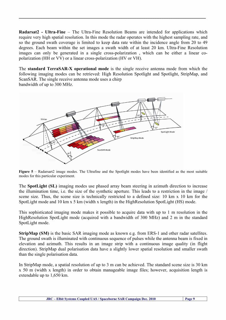
__________________________________________________________________________________
JRC ndash Elbit Systems Coupled UAS Spaceborne SAR Campaign Dec 2010 Page 9
Radarsat2 - Ultra-Fine ndash The Ultra-Fine Resolution Beams are intended for applications which require very high spatial resolution In this mode the radar operates with the highest sampling rate and so the ground swath coverage is limited to keep data rate within the incidence angle from 20 to 49 degrees Each beam within the set images a swath width of at least 20 km Ultra-Fine Resolution images can only be generated in a single cross-polarization which can be either a linear co-polarization (HH or VV) or a linear cross-polarization (HV or VH) The standard TerraSAR-X operational mode is the single receive antenna mode from which the following imaging modes can be retrieved High Resolution Spotlight and Spotlight StripMap and ScanSAR The single receive antenna mode uses a chirp bandwidth of up to 300 MHz
Figure 5 ndash Radarsart2 image modes The Ultrafine and the Spotlight modes have been identified as the most suitable modes for this particular experiment The SpotLight (SL) imaging modes use phased array beam steering in azimuth direction to increase the illumination time ie the size of the synthetic aperture This leads to a restriction in the image scene size Thus the scene size is technically restricted to a defined size 10 km x 10 km for the SpotLight mode and 10 km x 5 km (width x length) in the HighResolution SpotLight (HS) mode This sophisticated imaging mode makes it possible to acquire data with up to 1 m resolution in the HighResolution SpotLight mode (acquired with a bandwidth of 300 MHz) and 2 m in the standard SpotLight mode StripMap (SM) is the basic SAR imaging mode as known eg from ERS-1 and other radar satellites The ground swath is illuminated with continuous sequence of pulses while the antenna beam is fixed in elevation and azimuth This results in an image strip with a continuous image quality (in flight direction) StripMap dual polarisation data have a slightly lower spatial resolution and smaller swath than the single polarisation data In StripMap mode a spatial resolution of up to 3 m can be achieved The standard scene size is 30 km x 50 m (width x length) in order to obtain manageable image files however acquisition length is extendable up to 1650 km
__________________________________________________________________________________
JRC ndash Elbit Systems Coupled UAS Spaceborne SAR Campaign Dec 2010 Page 10
33 ndash Partners Involved and their Roles The partners involved in this experiment comprised the European Commission (EC) ndash Joint Research Centre (JRC) and Elbit Systems from Haifa Israel The role of each partner is briefly described next 331 - European Commission (EC) ndash Joint Research Centre (JRC) ndash The main role of the EC-JRC was the planning set up execution and the analysis of the data together with Elbit Systems This comprised
a) the definition of the objectives b) the research methods used c) the ground truth data collection d) the analysis of the data and the conclusions of the experiment
332 ndash Elbit Systems ndash The main role of Elbit Systems comprised
a) the deployment and operation of the boat used as target b) the deployment and operation of the UAS Hermes 450 c) the contacts with the Israeli authorities namely the Israeli Air Force and Civil Aviation
Authority d) the collection of ground truth data e) The analysis of the data and conclusions of the experiment
__________________________________________________________________________________
JRC ndash Elbit Systems Coupled UAS Spaceborne SAR Campaign Dec 2010 Page 11
4 ndash Experiment Execution
41 ndash Modus Operandi The modus operandi of the trial was as follows 1- JRC supplied Elbit Systems with the footprint (frame) of the spaceborne SAR images to be acquired (TerraSAR-X-Stripmap and Radarsat-2 Spotlight) as well as the time of the SAR satellite passes 2- The boat was deployed about 2 nautical miles Southwest of the Port of Haifa The boat was about 12-meter long The boat had a crew of 3 people plus one JRC staff 3- The boat left from the port of Haifa and travelled a couple of nautical miles to reach the test site Once the test site was reached the boat was stationary at the time of the satellite SAR overpass After the satellite overpasses the boat was steered at different speeds to test the tracking capabilities of the UAV
42 ndash Ground Truth Data Collection The ground truth data collected comprised a) the sea state b) Data from the UAS sensors b) the weather conditions and wind speed e) Photos and movies of the boats involved in the experiment
43 ndash Means Involved in the Experiment The means involved in the experiment comprised two satellite SAR images namely a TerraSAR-X-Stripmap and a Radarsat-2 Spotlight and one 12-meter long boat 431 ndash Boat Deployed During the Experiment Figures 6 illustrate the boat deployed as target during the experiment
__________________________________________________________________________________
JRC ndash Elbit Systems Coupled UAS Spaceborne SAR Campaign Dec 2010 Page 12
Figure 6 ndash The 12-meter boat deployed during the experiment at the Port of Haifa Israel 432 ndash Hermes 450 ndash System Overview The Hermesreg UAV system is a mature and operationally proven system with accumulated experience with the Israel Defense Forces operations and with other users worldwide It features a fully redundant architecture leading to a high level of safety and reliability a high level of autonomy modern high performance state-of-the-art payloads and a small logistic footprint Figure 7 shows the main elements of the Hermes UAV System 433 ndash The Air Vehicle Hermesreg 450W is a modern UAV design featuring highly efficient aerodynamics composite structure and a high level of system redundancy and autonomy Its compact size and high maximumempty weight ratio enable very high mission effectiveness delivering potent payloads high endurance and a modest logistic footprint The Hermesreg 450 is in production and has accumulated over 150000 flight hours with the Israeli Air Force and other users around the globe The Hermesreg 450W uses the higher power delivered by the AR802W engine to achieve higher gross weight with the same platform greatly increasing payload and fuel carrying capability a shorter takeoff run and expanded flight envelope
__________________________________________________________________________________
JRC ndash Elbit Systems Coupled UAS Spaceborne SAR Campaign Dec 2010 Page 13
The AR802W engine is a derivative of the AR802 rotary engine with widened rotor and housing The result is a 30 gain in power to nearly 70HP Coupled to an Electronic Fuel Injection system the engine is highly efficient and has improved maintenance figures Following is a summary of the physical characteristics of the Hermes 450W air vehicle is given in Table 2
Table 2 ndash Summary of Hermes 450 main characteristics Physical Characteristics
bull Length 61 m bull Wingspan 105 m bull Fuselage diameter 0508 mm bull Max takeoff weight 550 kg bull Max internal fuel weight (including oil) 115 kg bull Max payload weight 150 kg
Figure 7 ndash Elements of the Hermes UAV System
434 ndash Ground Control Station (GCS) The GCS is a transportable system designed to perform and support all Hermesreg UAV family ground Based activities operational activities These activities include mission planning pre-flight check takeoff and landing UAV flight control mission control payloads and systems control as well as post-mission debriefing An embedded or appended training capability is optional Remote communication of video and telemetry to a C4I center via SATCOM or WAN infrastructure is optional The GCS provides a user friendly comfortable effective and protected environment for carrying out UAV missions
__________________________________________________________________________________
JRC ndash Elbit Systems Coupled UAS Spaceborne SAR Campaign Dec 2010 Page 14
The GCS is housed in a shelter with operator consoles of advanced human engineering design that provide an ergonomic operational environment The shelter is based on the NATO ACE III shelter with a side door As Israelrsquos leading C4I provider Elbit Systems has incorporated Hermesreg GCS advanced C4I capabilities including comprehensive mission planning tactical database management and tactical coordination with supported forces and command elements The Hermesreg GCS is uniquely capable of performing two UAV missions concurrently with two UAVs each of which is controlled via a separate Ground Datalink Terminal (GDT) The Hermesreg GCS requires minimal operating personnel ie mission commander and mission operator
Figure 8 ndash The UAS Hermes 450 Ground Control Station (GCS)
435 ndash The EO Payload The CoMPASS Compact Multi Purpose Advanced Stabilized System is a day and night surveillance system that includes a 3rd generation 3-5 μm zoom FLIR camera a color zoom TV CCD camera and automatic tracking capabilities The CoMPASS enables the following
bull Day and night stabilized LOS observation with capabilities of target detection recognition and identification in various weather conditions
bull Automatic and manual tracking of targets bull Slaving CoMPASS Line of Sight (LOS) to external systems bull LOS information bull Target Laser designationampRanging or only Target Laser Ranging bull Laser Target Marker
__________________________________________________________________________________
JRC ndash Elbit Systems Coupled UAS Spaceborne SAR Campaign Dec 2010 Page 15
CoMPASS the EOIR system for UAV applications is the most advanced payload version of the CoMPASS family featuring reduced weight high degree of modularity and flexibility space-saving packaging and advanced operational and video processing features The CoMPASS based STA Stabilized Turret Assembly is a single LRU housing
bull 3rd generation 3-5 μm FLIR zoom Camera bull Color Zoom TV CCD Camera bull Laser Target Designator bull Laser Target Marker bull Electronic Boards
Figure 9 ndash CoMPASS Stabilized Turret Assembly (STA)
__________________________________________________________________________________
JRC ndash Elbit Systems Coupled UAS Spaceborne SAR Campaign Dec 2010 Page 16
5 ndash Preliminary Data Analysis
51 ndash SAR Satellite Imagery Processing The high resolution spaceborne SAR image was analysed visually because the resolution is good enough to allow visual analysis and the site is too close to the coast which makes automatic processing more difficult and prone to error due to artefacts caused by land targets The Hermes 450 images were also analysed visually
52 ndash Ground Truth Data This section briefly describes the Ground Truth data namely the GPS positions of the boat deployed as target during the experiment a photo of the boat as well as other relevant ground truth data collected
521 ndash GPS coordinates of the boat deployed Table 5 gives the GPS coordinates of the boat deployed during the experiment at the time of the Radarsat-2 satellite overpass Table 3 ndash Ground Truth data collected at the time of the satellite pass (154740 UTC=174740 LT) on 8 December 2010
Date 8 Dec2010 Time 154740 UTC=174740 LT Pass Ascending
SatelliteMode Radarsat-2 Spotlight Polarisation HH
Boats Type Size Latitude Longitude
Elbits 12-meter
Boat
32˚ 51830 N 32deg514980N 32863833deg N
34˚ 57961 E 34deg575766E 34966017deg E
__________________________________________________________________________________
JRC ndash Elbit Systems Coupled UAS Spaceborne SAR Campaign Dec 2010 Page 17
521 ndash HERMES 450 Ground Truth Data Table 4 shows the 12-meter Elbitacutes Boat as detected by the IR sensor of the Hermes 450 Table 4 ndash Hermes 450 Ground Truth Data Date 8 Dec2010 Time 154740 UTC=174740 LT
Platform Hermes 450
UAV Type Size Latitude Longitude
UAV Hermes
450
174730h 3284489947 N
174800h
3285089687 N
174730h 3498564048 E
174800h
3499338667 E
Elbits 12-meter
Boat UAV
Image
32˚ 51830 N 32deg514980N 32863833deg N
34˚ 57961 E 34deg575766E 34966017deg E
53 ndash Weather Conditions and Sea State The weather conditions in Haifa are summarized in Table 5 bellow
Table 5 ndash Wind speed wind direction and Temperature Time (IST) Temp Dew
Point Humidity Pressure Visibility Wind Dir
Wind Speed
Gust Speed Precip Events Conditions
550 PM 210 degC 130 degC 60 1017 hPa - North 111 kmh
31 ms - NA Clear
__________________________________________________________________________________
JRC ndash Elbit Systems Coupled UAS Spaceborne SAR Campaign Dec 2010 Page 18
Figure 10 gives the weather data (Temperature Barometric Pressure Wind Speed and Wind Direction) for Haifa Israel on 8 Dec 2010
Figure 10 ndash Weather data (Temperature Barometric Pressure Wind Speed and Wind Direction) for Haifa Israel on 8 Dec 2010
__________________________________________________________________________________
JRC ndash Elbit Systems Coupled UAS Spaceborne SAR Campaign Dec 2010 Page 19
54 ndash Verification of the Results This section briefly describes the verification of the targets detected in the spaceborne SAR image and in the Hermes 450 UAV using the ground truth data collected during the experiment
541 ndash Overview of the UAV Trajectory and the SAR Imagery Footprint Figure 11 gives an overview of the UAV trajectory the footprint of the SAR imagery and the area of the experiment near the port of Haifa The UAV trajectory is depicted in blue The large red rectangle is the footprint of the TerraSAR-X Stripmap The smaller red rectangle is the footprint of the Radarsat-2 Spotlight image
Figure 11 ndash Google Earth UAV trajectory during the experiment and footprinst of the SAR imagery ordered for the experiment Figure 12 is a zoom in of the previous image which allows a more detailed view of the UAV trajectory and of the port of Haifa Figure 13 is a zoom in of figure 12 It shows in more detail the UAV trajectory during the entire experiment and the port of Haifa in Israel
__________________________________________________________________________________
Figure 12 ndash Zoom in of the previous figure showing a more detailed view of the UAV trajectory and of the port of Haifa in Israel
Figure 13 ndash Zoom in of the previous figure showing a even more detailed view of the UAV trajectory and of the port of Haifa in Israel
JRC ndash Elbit Systems Coupled UAS Spaceborne SAR Campaign Dec 2010 Page 20
__________________________________________________________________________________
JRC ndash Elbit Systems Coupled UAS Spaceborne SAR Campaign Dec 2010 Page 21
542 ndash Targets Detected in the Radarsat-2 Spotlight Image Figure 14 illustrates the position of the Elbitrsquos boat used as target in the experiment at the approximate time of the SAR Satellite pass by 1547 UTC (1747 LT) The small photo of the boat shows the approximate position of the boat The two small planes show the positions of the UAV immediately before and after the SAR Satellite pass
Figure 14 ndash Google Earth positions of the elbitrsquos boat and the UAV (Hermes450) at the approximate time of the SAR Satellite overpass by 174740 UTC Figure 15 shows the corresponding SAR image (Radarsat-2 Spotlight) acquired during the experiment Pins 1 and 2 represent the positions of the UAV before and after the SAR satellite overpass Pin 3 illustrates the position of the Elbitacutes boat deployed at the time of the satellite overpass At this scale the SAR signature of the boat is not distinguishable from the sea clutter background However zooming in the SAR image the SAR signature can clearly be seen as illustrated in figure 12 The SAR image in figure 12 also shows several SAR signatures of large ships in the area at the time of the satellite overpass
__________________________________________________________________________________
JRC ndash Elbit Systems Coupled UAS Spaceborne SAR Campaign Dec 2010 Page 22
Elbit`s Boat
Figure 15 ndash On the background the SAR image with the two UAV positions before and after the satellite overpass (Pin1 and Pin2) and the Elbitacutes Boat position (Pin3) The small window over the SAR image shows a zoom in of the SAR image where the SAR signature of the Elbitacutes Boat can clearly be seen The top right are of the SAR image also shows SAR signatures of several large ships in the area at the time of the SAR satellite overpass Figure 16 shows the corresponding SAR image (Radarsat-2 Spotlight) acquired during the experiment and the UAV IR images of some of the targets Pins 1 and 2 represent the positions of the UAV before and after the SAR satellite overpass Pin 3 illustrates the position of the Elbitacutes boat deployed at the time of the satellite overpass At this scale the SAR signature of the boat is not distinguishable from the sea clutter background However zooming in the SAR image the SAR signature can clearly be seen as illustrated in figure 13 On the top left the UAV IR image of the Elbitrsquos Boat The SAR image in figure 13 also shows several SAR signatures of large ships in the area at the time of the satellite overpass On the centre left the UAV IR image of a large ship On the centre right the UAV IR image of a large ship On the bottom right the UAV IR image of a large ship All the UAV images were acquired at night in complete darkness from altitudes in the order of 5500 meters Nonetheless the quality and detail of the UAV images allows classification of the targets and in some cases the identification As it can be seen the potential of UAV for maritime surveillance is very promising During the experiment the UAV detected all the boats and ships in the area and tracked some of the boatsships to test the tracking capability The capability of detection and tracking targets is a critical capability for maritime surveillance
__________________________________________________________________________________
JRC ndash Elbit Systems Coupled UAS Spaceborne SAR Campaign Dec 2010 Page 23
Elbitacutes Boat
Elbit`s Boat
Figure 16 ndash Zoom-in of figure 15 with the UAV images of some targets On the top left the UAV IR image of the Elbitrsquos Boat On the centre left the UAV IR image of a large ship On the centre right the UAV IR image of a large ship On the bottom right the UAV IR image of a large ship Figure 17 shows a comparison of the SAR and UAV images with an optical photo taken in Haifa Israel a couple of hours before the SAR satellites overpass Most of the large ships were detected in the SAR image and some of these ships can be identified in the optical photo Some of the ships in the photo left the area before the SAR satellites overpass
__________________________________________________________________________________
JRC ndash Elbit Systems Coupled UAS Spaceborne SAR Campaign Dec 2010 Page 24
Figure 17 ndash Photo taken in Haifa Israel a couple of hours before the SAR satellites overpass This phot shows the large ships moored in the area Most of these large ships were detected in the Radarsat-2 image As expected their positions and orientations were slightly different at the time of the satellite overpass
Elbitacutes Boat
Elbit`s Boat
__________________________________________________________________________________
JRC ndash Elbit Systems Coupled UAS Spaceborne SAR Campaign Dec 2010 Page 25
Figure 18 ndash Photo taken in Haifa Israel a couple of hours before the SAR satellites overpass This phot shows the large ships moored in the area Most of these large ships were detected in the Radarsat-2 image As expected their positions and orientations were slightly different at the time of the satellite overpass Figure 18 illustrates the SAR image and the corresponding google earth image of a small pier in the port of Haifa In the SAR image due to several artefacts it is not possible to detect the 7 small boats moored to the small pier The UAR IR image of the same area clearly shows the 7 small boats with impressive detail taking into account that the image was acquired from an altitude of about 5500 meters A zoom in of the same UAV IR image is shown in figure 19 As it can be seen although the image was acquired from an altitude of about 5500 meters the 7 small boats can be clearly seen with enough detail to allow classification of the type of boat A UAV flight at lower altitude would probably giver a lot more detail and eventually allow the identification of the small boats
__________________________________________________________________________________
JRC ndash Elbit Systems Coupled UAS Spaceborne SAR Campaign Dec 2010 Page 26
Figure 19 ndash UAV IR image of a small pier in the port of Haifa Israel where 7 small boats can be seen with enough detail to allow classification This image was acquired from an altitude of about 5500 meters in the dark
__________________________________________________________________________________
55 ndash Quantitative Analysis of the Spaceborne SAR Image In order to allow a quantitative analysis of the data the spaceborne SAR image was calibrated using ESArsquos NEST software package version 4B The input was the SAR image acquired and the output was the Radiometric Calibration (Sigma Naught (σdeg)) expressed in terms of intensity and in decibel (dB) the Radar Brightness (βdeg) and the Radiometric Normalisation (gamma naught (γdeg))
551 ndash Radarsat-2-Spotlight 08Dec2010 (154740 UTC) Haifa Israel Figure 20 illustrates the Intensity band of a subset of the Radarsat-2Spotlgiht image (08Dec2010)
Figure 20 ndash Radarsat-2 Spotlgiht image (08Dec2010) ndash Sigma Naught (Intensity) band
JRC ndash Elbit Systems Coupled UAS Spaceborne SAR Campaign Dec 2010 Page 27
__________________________________________________________________________________
Figure 21 illustrates the Sigma Naught Coefficient of the Radarsat-2 Spotlgiht image (08Dec2010) expressed in terms of intensity and decibel (dB)
Figure 21 ndash Radarsat-2 Spotlgiht image (08Dec2010) - On the left the Sigma Naught (σdeg) (intensity) and on the right the Sigma Naught (σdeg) (dB)
ormalisation amma Naught (γdeg)) of the Radarsat-2 Spotlgiht image (08Dec2010) expressed in dB
-2 Spotlgiht image (08Dec2010) - On the left the Beta Naught (βdeg) and on the right the Gamma Naught (γdeg) (dB)
Figure 22 illustrates the Radar Brightness (Beta Naught (βdeg)) and the radiometric n(G
Figure 22 ndash Radarsat
JRC ndash Elbit Systems Coupled UAS Spaceborne SAR Campaign Dec 2010 Page 28
__________________________________________________________________________________ Figure 23 shows the Sigma Naught (σdeg) in dB after some colour manipulation and the histogram of the Sigma Naught (σdeg) image
Figure 23 ndash Radarsat-2 Spotlgiht image (08Dec2010) - On the top left the Sigma Naught (σdeg) after colour manipulation to enhance the targets and on the top right the corresponding histogram On the bottom we can see the histogram of the image
Table 6 gives the statistics of the Sigma Naught (σdeg) Radarsat-2 Spotlgiht image (08Dec2010) The Sigma Naught (σdeg) range from -72897 dB up to 23465 dB The Mean value is -16855 dB the Median is -16594 dB and the standard deviation is 7077 dB
JRC ndash Elbit Systems Coupled UAS Spaceborne SAR Campaign Dec 2010 Page 29
__________________________________________________________________________________
JRC ndash Elbit Systems Coupled UAS Spaceborne SAR Campaign Dec 2010 Page 30
Table 6 ndash Statistics of the Radarsat-2 Spotlgiht image (08Dec2010) (154740 UTC)
Statistics Values Unit Only ROI-Mask pixels considered Number of pixels total Number of considered pixels Ratio of considered pixels
No 322394283 322394283
1000
Minimum Maximum
-728974609375 234655818939209
intensity_db intensity_db
Mean Median Std-Dev Coefficient of Variation
-16855686580177853 -1659462338617847 707796800831575
07888765273432338
intensity_db intensity_db intensity_db intensity_db
Checking the radar backscattering coefficient of some targets (small boat and some large ships) detected in the Radarsat-2 Spotlight image we get values ranging from -0379 dB up to 23455 dB The analysis of the Sigma Naught values (σdeg) of the targets and the area around the targets shows a significant contrast
56 ndash Summary of the Preliminary Analysis of the Spaceborne SAR Image This experiment involved two spaceborne SAR images namely a TerraSAR-X Stripmap and one Radarsat-2 Spotlight The TerraSAR-X image was not delivered by DLR due to technical problems The Elbitrsquos boat deployed during the experiment was detected in the Radarsat-2 Spotlight image Several other targets including a set of large ships were also detected Table 7 summarises the characteristics of the SAR image acquired and the targets detected
Table 7 ndash List of SAR Satellite Images acquired during the experiment and detected boats ISRAEL (HAIFA)
Date Time Place Satellite Mode Ground Truth Data Detected Boats
08Dec2010 (PM) Haifa - Israel Radarsat-2 Spotlight GPSPhotosMovies 1 small boat deployed + 9 large ships
Table 8 gives the minimum and maximum Sigma Naught (σdeg) of the targets detected in each SAR image
Table 8 ndash Minimum and maximum Sigma Naught (σdeg) of the targets detected in each SAR image
Date Time UTC (LT)Pass Satellite Image Mode Polarisation Sigma Naught (σdeg) Min Max
29Oct2010528UTC(728AM LT) DES Radarsat-2 Spotlight HH --0379 dB 23455 dB The SAR signatures of the boats deployed were very weak Some possible reasons to explain such weak signatures are the sea state the wind speed the incidence angle and the type and materials Another possible reason is the processing at DLR
__________________________________________________________________________________
JRC ndash Elbit Systems Coupled UAS Spaceborne SAR Campaign Dec 2010 Page 31
6 ndash Preliminary Conclusions The analysis of the results of this coupled UASSpaceborne SAR experiment shows a promising potential for the use of UAS for maritime surveillance UAS can be integrated into the airborne building block of maritime surveillance systems to complement the existing assets increase system performance and improve the overall maritime domain awareness The main perceived maritime security and safety threats comprise piracy terrorist and military threats weapons proliferationsmuggling drugs trafficking illegal immigration unlawful use of containers attacks to critical infrastructures and illegal fishing The main maritime security and safety gaps include a lack of technologies with the capability of detecting small targets (eg small boats) a lack of wide area and persistent maritime surveillance a lack of coordination and information sharing limited interoperability a lack of containers security a lack of persistent surveillance of critical infrastructures and early warning systems Unmanned Aircraft Systems (UAS) are an emerging technology with strong potential to mitigate the above mentioned threats by filing in the main maritime security and safety gaps listed earlier For instance the wide range of potential applications of UAS to maritime surveillance includes but is not limited to
bull detection classification and identification of small boats bull persistent maritime surveillance bull use as communications relays bull persistent surveillance of critical infrastructures bull early warning systems bull COMINT and ELINT collection etc
Table 11 illustrates the mapping of maritime securitysafety threats vs gaps and summarises the main potential applications of UAS to maritime surveillance The above mentioned potential applications of UAS to the Maritime Domain will be addressed in turn in more detail next bull Detection classification and identification of small boats ndash The capability of detecting classifying and identifying small targets (eg small boats) is among the key technologies required to improve maritime domain awareness This capability is critical to mitigate piracy illegal immigration drugs trafficking weapons smuggling illegal fishing terrorism and critical infrastructure Unmanned Aircraft Systems (UAS) provide this capability more efficiently and at a lower cost than any other existing technology bull Persistent maritime surveillance ndash With the continuous improvements of UAS technologies such as platforms sensors collision avoidance systems command and control systems telecommunications etc UAS are increasing their autonomy endurance and flexibility These characteristics are very important for persistent maritime surveillance UAS can be launched from land ships aircraft and technologies to launch UAS from submarines are currently under development UAS have distinct advantages over other existing technologies for persistent maritime surveillance in terms of autonomyendurance (the Global Surveyor has an autonomy of 1 week) cost (eg as the autonomy of UAS increases the number of staff required to operate UAS decreases) risk (eg if the UAS crashes the crew is not at risk) flexibility (eg they can be launched from a ship reducing the time to reach potential threats) etc
__________________________________________________________________________________
JRC ndash Elbit Systems Coupled UAS Spaceborne SAR Campaign Dec 2010 Page 32
bull Communications relays ndash UAS are being used as communication relays mainly in military context but have the potential to play a similar role in Civil context in several situations such as to replace satellite communications or as a redundant system over any location on Earth The main advantages of using UAS as communication relays is that airborne communication relays mitigate kinetic and noise jamming threats to satellite communications uplinks by providing an alternative set of links either directly to surface-based terminals or to satellites beyond the range of threats They are less susceptible to noise jamming threats than satellites because an adversary has to detect geolocate and track the airborne asset and operate within line of sight of the receive antenna main beam bull Persistent surveillance of critical infrastructures ndash The security of critical infrastructures such as nuclear power plants refineries ports etc requires persistent surveillance UAS can play an important role in providing persistent surveillance over critical infrastructures and over a wide area around the critical infrastructure Some advantages of UAS over other existing technologies such as ground-based assets (eg video cameras alarm systems manned aircraft etc) comprise the security of the UAS (eg hardly can be damaged or switched off as any ground-based asset) the area covered by a UAS (eg it is larger than the area covered by any ground-based asset) the cost (eg UAS is cheaper than manned aircraft with similar capability) etc bull Early warning systems ndash UAS have the potential to be used as part of an integrated system of systems for early warning A UAS can provide information about a given area at a fraction of the cost of alternative means Formation flying of UAS can cover a wide maritime area It is reasonable to assume that in a foreseeable future with the advent of UAS with increased autonomy the operations cost of UAS will likely decrease making them increasingly more attractive bull COMINT and ELINT collection ndash SIGNal INTelligence (SIGNINT) can be divided into two categories namely COMINT and ELINT COMINT stands for Communication Intelligence and ELINT for Electronic Intelligence Collection of COMINT is passive Exploitation of COMINT requires a human operator which implies COMINT UAS are suitable for COMINT and ELINT collection in different scenarios The relatively reduced amount of data collected and analysed during this experiment and the lessons learned do not allow drawing final conclusions about the feasibility of using Unmanned Aerial Systems (UAS) for maritime surveillance However this experiment allowed hands-on experience with UAS technologies and significantly improved the awareness for its applications to maritime surveillance and related issues involved including its potential the feasibility as well as the limiting and enabling factors These different aspects will now be analysed in turn in the next sections Table 11 illustrates the mapping of the main maritime security threats and gaps as well as the main priorities in terms of the different technologies involved in maritime surveillance For each maritime threat the technologies required to fill in each gap is indicated and its priority is expressed in a range of numbers (1 to 3 1 = Maximum Priority 2 = Medium Priority 3 = Low Priority) and colours (Red = Maximum Priority Orange = Medium Priority Green = Low Priority) The main technologies involved in maritime surveillance are listed on the bottom of figure 4 and are reproduced here for convenience of the reader 1- Reporting Systems 2- Sensors 3- Platforms 4- Communications 5- Data Fusion amp Sharing 6- Intelligence and 7- Databases For example the mitigation of the main threat Piracy requires filling in several maritime security gaps (eg lack of persistent surveillance lack of wide-are maritime surveillance lack of small boat detection lack of Early Warning Systems and lack of Information Sharing with maximum priority (1- Red) and among the required technologies listed are UAS LTAAV GEO-HR etc Concerning the remaining two gaps (Limited Interoperability and Containers Security) they are less relevant to mitigate Piracy hence the priority for Limited Interoperability is 2-Orange and for Containers Security is 3- Green
__________________________________________________________________________________ Table 9 ndash The Main Maritime Security and Safety Threats vs Gaps and the technologies that can be used to mitigate them
Maritime Security Main Threats GapsGapsrarr
darrThreats
Lack o f Risk As sessmentCapab ility
La ck of Persiste nt
Surveilla nce
La ck of Wid e-Area su rve illanc e
La ck of Small Boat De tecti on
Lack o f Earl y Warn ing Sys tems
L ack of In forma tion
Sh arin g
L imi ted In terop era bility
Lac k of Co ntai ners
Se cur ity
bull PiracyUAS LTAVG EO-
HR + UAS LT AVGEO-
HR + SAR GEO-HR
+ UAS USV LTAV
+ UAS LTAV
+ Coord in ationamp Sharing +
Inter opera bilityOptimisation +
1 2 3 5 6 7 1 2 3 5 6 7 1 2 3 5 6 1 2 3 123456 4567 1234567 1234567
bull Terro rismUAS LTAVG EO-
HR + UAS L TAV GEO-HR +
SAR AISGEO-HR +
UAS USV LTAV+
Intelligence+
Inte lligen ce+
Inter opera bilityOptimisation +
Intelligence+
1 2 3 5 6 7 1 2 3 5 6 1 2 3 5 6 1 2 3 123456 4567 1234567 1234567
bull Wea pon s ofM ass Dest ru ctio n Smugg ling
UAS LTAVG EO-HR +
UAS LT AVGEO-HR +
SAR AIS+
UAS USV LTAV+
Intelligence+
Inte lligen ce+
Intelligence+
Intelligence+
1 2 3 5 6 7 1 2 3 5 6 1 2 3 5 6 1 2 3 123456 4567 1234567 1234567
bull Drug sTraffic king
UAS LTAVG EO-HR +
UAS LT AVGEO-HR +
SAR AIS+
UAS USV LTAV+
Intelligence+
Inte lligen ce+
Intelligence+
Intelligence+
1 2 3 5 6 7 1 2 3 5 6 1 2 3 5 6 1 2 3 123456 4567 1234567 1234567
bull Illega lImmigratio n
UAS LTAVG EO-HR +
UAS LT AVGEO-HR +
SAR AIS+
UAS USV LTAV+
Intelligence+
Inte lligen ce+
Intelligence+
Intelligence+
1 2 3 5 6 7 1 2 3 5 6 1 2 3 5 6 1 2 3 123456 4567 1234567 1234567
bull Critic alI nfrastruc tureSecu rit y
UAS LTAVG EO-HR +
UAS LT AVGEO-HR +
SAR AIS+
UAS USV LTAV+ + Inte lligen ce
+ Intelligence
+ Intelligence
+
1 2 3 5 6 7 1 2 3 6 1 2 3 5 6 1 2 3 123456 4567 1234567 1234567
bull Illega lFish ing
UAS LTAVG EO-HR +
AI S+SAR UASLTAV +
SAR AIS GEO-HR+
UAS USV LTAV+
Intelligence+
Inte lligen ce+
Intelligence+
1 2 3 5 6 7 1 2 3 5 7 1 2 3 5 6 1 2 3 123456 4567 1234567
bull Un lawf ul Use of Co nta iners
(Secur ity)
UAS LTAVG EO-HR +
GPS Tr acking+
Intelligence+
Inte lligen ce+
GPS Int rusion Det ection Se al
1 2 3 5 6 7 4 6 7 1 2 3 5 6 1 2 3 123456 4567 1234567 1234567
(-) Priority (+) Not Rel evant
SURVEILLANCETECHNOLOGIES
1- Reporti ng Systems
2 -Sensors 3 -P latforms 4 - Communications 5- Data Fusionamp Sharing
6 -I ntelli gence 7 -Databases
JRC ndash Elbit Systems Coupled UAS Spaceborne SAR Campaign Dec 2010 Page 33
__________________________________________________________________________________
JRC ndash Elbit Systems Coupled UAS Spaceborne SAR Campaign Dec 2010 Page 34
61 ndash Hands-on experience with UAS technologies and its applications to maritime surveillance This coupled UASSpaceborne SAR campaign was a unique opportunity to acquire further handsndashon experience with UAS technologies and learn about the main issues related to its applications to maritime surveillance From the planning phase up to the execution of the UAS flight and landing there are several factors that need to be carefully analysed and taken into account A summary of the main issues identified in this experiment is given next 1- Selection of the Experiment Area Authorisation to Fly ndash For the time being UAS can only be flown in restricted areas usually under control of national authorities often the military This is due to the risks that a UAS can pose to human life and property In the present case an area under the authority of the Israeli Civil Aviation Authority was selected The authorisation to fly was not easy to obtain because the selected area is under the authority of the Civil Aviation Authority Figure 24 indicates the area of the experiment in Haifa Israel 2- UAS Communications Issues ndash The Hermes 450 was flown in Line-of-Sight (LOS) since it was close to the coast For BLOS (Beyond Line-of-Sight) operation satellite communications are required 3- Synthetic Aperture Radar (SAR) ndash The specific model Hermes 450W used in the experiment had no SAR sensor installed However a SAR sensor can be installed A SAR sensor is important for maritime surveillance since it allows 247 operations regardless of the weather conditions 4- Automatic Identification System (AIS) Receiver ndash The Hermes 450 used in this experiment was not equipped with an AIS receiver For maritime surveillance operations an AIS receiver is a very important tool since it allows the automatic identification of most ships allowing the UAS to concentrate on non-identified ships
__________________________________________________________________________________
Figure 24 ndash The area of the experiment is indicated by the GPS Trajectory of the UAV
62 ndash Potential of UAS for Maritime Surveillance UAS technologies are relatively recent and involve a wide range of fields spanning from aeronautics and sensors technologies to satellite communications and other engineering disciplines Innovations in each of the fields involved are emerging by the day UAS still have a long way to go before they become mature and their use fully operational For the time being UAS are mainly used for military applications However a large number of non-military UAS applications have been identified by stakeholders and there are several studies and demonstration flights foreseen for the near future Maritime surveillance is one of the most challenging and promising fields of application of UAS The challenges are due to the very demanding conditions under which the UAS must operate over sea and the requirements for safe operation
JRC ndash Elbit Systems Coupled UAS Spaceborne SAR Campaign Dec 2010 Page 35
__________________________________________________________________________________
JRC ndash Elbit Systems Coupled UAS Spaceborne SAR Campaign Dec 2010 Page 36
The present UAS experiment has unveiled some of the potential of UAS for maritime surveillance The UAS tests performed during this experiment include
1 ndash Detection of a Small rubber Boat and a Fishing Ship 2 ndash Tracking of a Small Boat and a Fishing Ship 3 ndash Classification of a Small Boat and a Fishing Ship 4 ndash Identification of a Small Boat and a Fishing Ship 5 ndash Detection and Tracking of People on the Beach
Despite the operational requirement that prevented the UAS from flying bellow 3km the experiment has confirmed the capability of UAS for small boat detection tracking and classification as well as the capability for people detection and tracking Concerning the identification of the targets the characteristics of the images acquired during this mission suggest that flying at lower altitudes the UAS images would allow the identification of the targets The UAS images can be seen from Figure 15 to 20
621 ndash Advantages of UAS for maritime Surveillance Some of the advantages of using UAS for maritime surveillance have been described in the literature and are summarized bellow
1- One potential benefit of UAS is that they could fill in a gap in current maritime surveillance by improving coverage
2- The range of UAS is a significant asset when compared to border agents on patrol or stationary surveillance equipment
3- Eletro-Optical InfraRed (EOIR) sensors (cameras) can identify small size objects from very high altitudes (high resolution)
4- UAS can provide precise and near-real-time imagery to a ground control operator who would then disseminate that information so that informed decisions regarding the deployment of border patrol agents can be made quickly
5- Long endurance UAS used along the border can fly for more than 30 hours up to several days without having to refuel compared with manned helicopterrsquos average flight time of just over 2 hours
6- The ability of UAS to loiter for prolonged periods of time has important operational advantages over manned aircraft
7- The longer flight times of UAS means that sustained coverage over a previously exposed area may improve maritime security
8- The range of UAVs is a significant asset when compared to border agents on patrol or stationary surveillance equipment Nevertheless the extended range and endurance of UAVs may lessen the burdens on human resources at the borders
9- UAS accidents do not risk the lives of pilots as do the helicopters and aircraft currently used by Coast Guards for border patrolling
__________________________________________________________________________________
JRC ndash Elbit Systems Coupled UAS Spaceborne SAR Campaign Dec 2010 Page 37
622 ndash Possible Drawbacks of using UAS for maritime Surveillance UAS also have disadvantages some of them are briefly described next
1- There have been concerns regarding the high accident rate of UAS which can be multiple times higher than that of manned aircraft Because UAS technology is still evolving there is less redundancy built into the operating system of UAS than of manned aircraft and until redundant systems are perfected mishap rates are expected to remain high
2- If control systems fail in a manned aircraft a well-trained pilot is better positioned to find the source of the problem because of hisher physical proximity If a UAS encountered a similar system failure or if a UAS landing was attempted during difficult weather conditions the ground control pilot would be at a disadvantage because he or she is removed from the event Unlike a manned pilot the remote pilot would not be able to assess important sensory information such as wind speed
3- Inclement weather conditions can also impinge on a UAS surveillance capability especially UAS equipped with only an EO camera and Forward Looking Infrared Radar (FLIR) because cloudy conditions and high humidity climates can distort the imagery produced by EO and FLIR equipment The effects of extreme climatic or atmospheric conditions on sensors reportedly can be mitigated with the outfit of one synthetic aperture radar (SAR) system and a moving target indicator (MTI) radar However adding SAR and MTI to a UAS platform would increase the costs associated with using UAS
4- Depending on the type of UAS the costs of operating a UAS can be higher than the costs of operating a manned aircraft This is because some types of UAS require a significant amount of logistical support and specialized operator and maintenance training Operating one UAS may require a crew of up to 20 support personnel The high comparative costs of operating some sophisticated types of UAS may be offset somewhat by their comparatively lower unit costs
63 ndash Main Limiting Factors Preventing the Use of UAS Several pre-requisites must be satisfied to render the UAS a viable cost-effective and regulated alternative to existing resources Major civil and commercial market barriers include
Single European Sky Sense and Avoid technologies Command and Control Technologies Reliability Communications (Bandwidth LOS BLOS)
Lack of airspace regulation that covers all types of UAV systems (encompassing lsquosense and avoidrsquo airspace integration and airworthiness issues)
Affordability - price and customization issues (eg commercial off-the-shelf open modular architecture) Lack of efforts to establish joint customer requirements (although this is gradually changing) Liability for civil operation Capacity for payload flexibility Lack of sufficient secure non-military frequencies for civil operation Perceived reliability (eg vehicle attrition rate vs manned aircraft) Operator training issues Recognitioncustomer perception of the UAV market Technology developments for multi-mission capability
__________________________________________________________________________________
64 ndash UAS Key Enabling Technologies Figure 25 illustrates the components of a typical UAV System showing some of the capabilities needed and the enabling technologies required for performing a given mission Any UAV mission involves many capabilities and technologies Due to the depicted system complexity the main key players such as the US Department of Defense (DoD) and other agencies have started to use the term Unmanned Aerial System (UAS) in place of UAV
Figure 25 ndash Unmanned Aerial Vehicle System Enabled by Autonomous Mission Management Reliable Flight Systems Navigation Accurate Systems Terrain Avoidance Power and Propulsion Some UAS key enabling technologies are listed below
Autonomous Mission Management Collision Avoidance Intelligent System Health Monitoring
Reliable Flight Systems Sophisticated Contingency Management Intelligent Data Handling and Processing Over-the-Horizon Communication Network-Centric Communication Open Architecture Power and Propulsion Navigation Accurate System Technology Enhanced Structures
JRC ndash Elbit Systems Coupled UAS Spaceborne SAR Campaign Dec 2010 Page 38
__________________________________________________________________________________
JRC ndash Elbit Systems Coupled UAS Spaceborne SAR Campaign Dec 2010 Page 39
Table 12 gives a more detailed description of other critical technologies for emerging autonomous UAV systems both civil and military Most of the technologies mentioned in Table 12 apply both to civil and military UAV systems Table 10 ndash Key Enabling Technologies (from SG75 study on autonomous systems)
Critical Technologies Decision Making Software
bull Fuzzy-based decision making bull Knowledge-based system bull Case-based reasoning bull Self-learning techniques bull Decision tree evaluation bull ReasoningInferring bull Probabilisticstochastic reasoning
Prediction Algorithms bull Predictive pathintent algorithms bull Short reaction algorithm bull Effectiveness evaluation
Status Assessment Software bull Internal status analysis bull Self-orientation
Situation Analysis Software bull Situation analysis bull Environmental analysis bull External status analysis
Modelling Software bull Air vehicle modelling algorithms bull Sensor modelling algorithms bull Scenario generation bull Threat system modeling bull Attack simulation bull Mission success optimisation model bull Simulation
Sensor Processing Software bull Sensor fusion bull Area of interest identification bull Automatic target recognition
Adaptive and Self-learning Systems bull Failure self-compensation
Attack Planning Software bull Attack plans and tactical alternatives bull Plan change impact identification
Weapon Engagement Procedure Software bull Weapon engagement algorithms
Mission Plan Update Software bull Route planning system bull Payload plan management system bull Mission Success Optimisation model
Path Optimisation Software bull Optimal trajectory planning bull Path Optimisation System
Targeting Software bull Target tracking bull Target prioritisation
Platform Technologies bull Obstacle detection and avoidance (airborne) bull Obstacle detection and avoidance (ground) bull Improved autopilot bull Speech recognition
Figure 26 summarises system element designs needed to transition from current to next-generation autonomous UAV systems for civilian and military UAS
__________________________________________________________________________________
Figure 26 ndash System Element Designs Needed to Transition from Current to Next-Generation Autonomous UAV Systems These new paradigms are a combination of system attributes and technological capabilities For instance the data fusion secure anti-jam and coordinated multi-vehicle control require technological development as well as specific system development to bring full maturity to unmanned systems Finally very small Micro UAVs (MAVs) and relatively large sophisticated UCAV systems are examples of the range of UAVs that are applying the new platforms payloads onboard processing communications etc to create next generation automated UAVs It is with these new platforms payloads etc that both UCAVs and MAV will be able to address similar operational challenges including
Mixed operation with other assets bull Deconfliction collision avoidance C4I integration
Operation over populated areas bull Safety issues Need to reduce reliance on communications bull UCAV ndash countermeasures bull MAV ndash limited size and power bull Limited line of sight environment Need a fully integrated system bull MAV propulsionpower generation still critical bull Operator machine interface critical bull All weather operations bull Survivability
JRC ndash Elbit Systems Coupled UAS Spaceborne SAR Campaign Dec 2010 Page 40
__________________________________________________________________________________
JRC ndash Elbit Systems Coupled UAS Spaceborne SAR Campaign Dec 2010 Page 41
65 ndash Mission Readiness
651 ndash Mission Readiness Summary This section summarises civil UAV mission readiness The purpose of Mission Readiness is to assess the readiness status of the different technologies involved in UAS In the present case this civil UAV mission readiness based on technology maturation forecasts that meet or exceed the desired or required capabilities identified by the user community Figure 27 summarises the mission readiness time forecasts for the different technologies The technologies annotated with an asterisk () are shown within the figure with maturation forecasts based on development targets expressed in the US Department of Defencesrsquo UAV Roadmap document The purpose of the chart is to be able to identify when the capability to fly a particular mission can be expected as a function of time The left-most end is the least probable and the right end the most probable timeframe
Figure 27 ndash Technology Maturation Summaries in Terms of Mission-Derived Capabilities
__________________________________________________________________________________
JRC ndash Elbit Systems Coupled UAS Spaceborne SAR Campaign Dec 2010 Page 42
66 ndash Small Boat Detection in SAR Satellite Imagery The use of spaceborne SAR imagery for small boat detection requires additional small boat detection experiments under different conditions using different methods It is not possible to draw final conclusions based on a limited number of small boat detection experiments which are not representative of the multiple possible scenarios
67 ndash Limitations of current State-of-the-Art SAR Satellite technology The main limitations of current State-of-the-Art spaceborne SAR imagery for maritime surveillance in particular aimed at small boat detection are 1 - SAR satellites repeat cycles do not allow the coverage of the same area at the required time intervals Constellations of SAR satellites could be a solution 2 - The conflict between resolution and image swath High resolution is required to detect small boats However the high resolution images have small swaths Maritime surveillance with high resolution images would require a large number of images to cover wide maritime areas which is very expensive and for the time being technically not feasible Intelligence data can play an important role by indicating an approximate position of suspicious non cooperative targets therefore reducing the surveillance area which can then be imaged using high resolution images 3- Spaceborne high resolution SAR imagery acquisition times are long enough to allow significant motion of the target during the acquisition time degrading the quality of the image Further research efforts are needed to develop new sensors and platforms As far as sensors are concerned shorter integration times are needed to prevent the blurring effect caused by the motion of the targets Regarding the platforms more platforms are needed to allow lower repeat cycles and improved coverage
__________________________________________________________________________________
JRC ndash Elbit Systems Coupled UAS Spaceborne SAR Campaign Dec 2010 Page 43
7 ndash Plans for Future Work The controlled experiments carried out by the EC-JRC together with Elbit Systems in Haifa-Israel comprised the deployment of a UAS (Hermes-450) and one small 12-meter boat A Radarsat-2 Spotlight image was acquired and several images collected by the Hermes-450 The experiment unveiled the potential of UAS for maritime surveillance in particular for detection tracking classification and possible identification of small targets The UAS was able to detect track and classify small targets such as small boats For low UAS altitude flights identification may be possible in some cases The small 12-meter boat was detected in the spaceborne SAR image The small boat detection trials carried out by the JRC were very successful since most small boats deployed during the experiments were detected in different sea states wind speeds and geographical locations The several small boat detection campaigns conducted by the EC-JRC seem to suggest that the probability of detection of small boats in spaceborne SAR images strongly depends on factors such as the sea state the wind speed the type of boat (shape and materials) the weather conditions among other factors The results of the experiments conducted thus far are not enough to draw final conclusions about the feasibility of using spaceborne SAR imagery for small boat detection However the experiments have an overall positive outcome because they indicate that under suitable sea state and wind speed conditions it is possible to detect small boats using spaceborne SAR The estimation of the probability of detection of small boats in spaceborne SAR images requires a large number of experiments under different circumstances (eg sea state wind speed characteristics of the targets image type and mode etc) Future plans include additional UAS experiments to asses its potential for maritime surveillance
Acknowledgements ndash The authors would like to express their gratitude to Elbit Systems for their cooperation logistical support and assets deployed without which the present coupled UASSAR Satellite Small Boat Detection Campaign would have not been possible
__________________________________________________________________________________
JRC ndash Elbit Systems Coupled UAS Spaceborne SAR Campaign Dec 2010 Page 44
REFERENCES [1] Elbit Systems ldquoUAV Elbit Systems Proposal for Unmanned Aerial Vehicle (UAV) flight to
collect Ground Truth data during a Maritime Surveillance Campaign and demonstrate UAV capabilities for Maritime Surveillancerdquo 2010
[2] ndash Cheryl Yuhas Suborbital Science Program Manager NASA Science Mission Directorate ldquoEarth Observations and the Role of UAVs A Capabilities Assessment Version 11rdquo Civil UAV Assessment Team httpwwwnasagovcentersdrydenresearchcivuavindexhtml August 2006
[3] ndash Document NIAG (SG75) NATO Industrial Advisory Group Study Group 75 Pre-Feasibility Study on UAV Autonomous Operations 2004
[4] ndash United States Department of Defence (DoD) Directive 50001 ldquoThe Defense Acquisition Systemrdquo and DoD Instruction 50002 ldquoOperation of the Defense Acquisition Systemrdquo
[5] ndash Mr James Ramage Mr Massimo Avalle Dr Erik Berglund Dr Luigi Crovella Mr Robert Frampton Dr Uwe Krogmann Mr Christian Ravat Mr Mike Robinson Dr Axel Schulte Dr Scott Wood ldquoRTO-TR-SCI-118 - Automation Technologies and Application Considerations for Highly Integrated Mission Systemsrdquo RTO-TR-SCI-118 AC323(SCI-118)TP204 January 2009
[6] Victor MG Silva Gilles Jurquet Gabriel Marchalot Maria TG Calzado Txema Soroa Juan Sancho Adam Koubek Harm Greidanus and Claudio Savarino ldquoWide Maritime Area Airborne Surveillance (WIMA2S) WP5 Final Reportrdquo WIMAAS WP5 FP7 Project 2008-2011 - ISBN-978-92-79-22801-8 (print) 978-92-79-22802-5 (PDF) ISSN-1018-5593 (print) 1831-9424 (online) EC-JRC Scientific Report JRC 70093 2012
[7] Victor MG Silva and Harm Greidanus ldquoSpaceborne SAR Small Boat Detection Campaign in Portugal and Spainrdquo EUR 25281 EN ISBN 978-92-79-22553-6 ISSN 1831-9424 (online) EC-JRC Scientific Report JRC68160 2012
[8] Goncalves Da Silva V Van Wimersma Greidanus H Hejmanowska B Loudjani P ldquoUAS Applications With Societal Benefits ndash JRCrsquos UAS-Related Activitiesrdquo 2011-2012 UAS Yearbook - UAS Unmanned Aircraft Systems - The Global Perspective 9 (9) 2011 p 127-129 JRC66600
[9] Goncalves Da Silva V Van Wimersma Greidanus H ldquoSmall boat detection using TerraSAR-X and Radarsat2 satellite imageryrdquo 4th TerraSAR-X Science Team Meeting 14 February 2011 DLR Oberpfaffenhofen (Germany) German Aerospace Center (DLR) (Organiser) 2011 JRC63663
[10] V Silva Harm Greidanus ldquoJRC - SAR Satellite Small Boat Detection Campaign - Portoroz ndash Sloveniardquo - ISBN-13 978-92-79-21476-9 ISSN (online) 1831-9424 EC-JRC Scientific Report JRC66835 2011
[11] V Silva Harm Greidanus ldquoJRC - SAR satellite small boat detection campaign - Algarve Portugalrdquo - ISBN-13 978-92-79-21265-9 ISSN (online) 1831-9424 ISSN (print) 1018-5593 EC-JRC Scientific Report JRC66631 2011
[12] ndash Goncalves Da Silva V Van Wimersma Greidanus H ldquoJRC-Frontex Spaceborne SAR Small Boat Detection Campaign ndash Italy amp Spainrdquo - ISBN-13 978-92-79-22213-9 ISSN (online) 1831-9424 EC-JRC Scientific Report JRC67517 2011
[13] - PW Vachon SJ Thomas J Cranton HR Edel and MD Henschel Validation of ship detection by the RADARSAT synthetic aperture radar and the Ocean Monitoring Workstation Canadian Journal of Remote Sensing 26(3)200ndash212 2000
[14] - Crisp D (2004) The state-of-the-art in ship detection in Synthetic Aperture Radar imagery DSTO Information Sciences Laboratory Australia
[15] - Joint Research Centre (JRC) of the European Community mdash IMPAST and DECLIMS web site httpintelligencejrcceceuintmarinefishindexhtm
[16] - McCandless SW Jackson CR (2004) Principles of Synthetic Aperture Radar Synthetic Aperture Radar Marine Users Manual NOAA Washington pp 1-23
[17] - Greidanus H (2008) Satellite Imaging for Maritime Surveillance of the European Seas Remote Sensing of the European Seas 343-358
European Commission
EUR 25346 EN --- Joint Research Centre --- Institute for the Protection and Security of the Citizen
Title JRC --- Elbit Systems Coupled UAS and Spaceborne SAR Campaign in Israel
Authors Victor MG Silva Harm Greidanus
Luxembourg Publications Office of the European Union
2012 --- v+44 pp --- 210 x 297 cm
EUR --- Scientific and Technical Research series --- ISSN 181-9424 (online) ISSN 1018-5593 (print)
ISBN 978-92-79-25020-0
doi10278828527
Abstract The European maritime area is one of Europersquos most important assets with regard to resources security and ultimately
prosperity of the Member States A significant part of Europersquos economy relies directly or indirectly on it It is not just the
shipping or fisheries industries and their related activities It is also shipbuilding and ports marine equipment and offshore
energy maritime and coastal tourism aquaculture submarine telecommunications blue biotech and the protection of the
marine environment The European maritime area faces several risks and threats posed by unlawful activities such as drugs
trafficking smuggling illegal immigration organised crime and terrorism Piracy in international waters also constitutes a threat
to Europe since it can disrupt the maritime transport chain These risks and threats can endanger human lives marine resources
and the environment as well as significantly disrupt the transport chain and global and local security It is anticipated that these
risks and threats will endure in the mid and long run In order to keep Europe as a world leader in the global maritime economy
an effective integratedinteroperable sustainable maritime surveillance system and situational awareness are needed
A significant number of unlawful maritime activities such as illegal immigration drugs trafficking smuggling piracy and
terrorism involve mainly small boats because small boats are faster and more difficult to detect using conventional means
Hence it is very important to find out the feasibility of using Unmanned Aerial Systems (UAS) for small boat detection tracking
classification and identification as well as to study the potential of UAS for maritime surveillance Since 2010 the EC-JRC has
carried out a number of UAS maritime surveillance campaigns to study the potential of UAS for maritime surveillance in
particular for small boat detection This report presents the results and conclusions of the JRC --- Elbit Systems Coupled UAS and
Spaceborne SAR campaign carried out in Dec 2010 in Haifa Israel
As the Commissionrsquos in-house science service the Joint Research Centrersquos mission is to provide EU policies with independent evidence-based scientific and technical support throughout the whole policy cycle Working in close cooperation with policy Directorates-General the JRC addresses key societal challenges while stimulating innovation through developing new standards methods and tools and sharing and transferring its know-how to the Member States and international community Key policy areas include environment and climate change energy and transport agriculture and food security health and consumer protection information society and digital agenda safety and security including nuclear all supported through a cross-cutting and multi-disciplinary approach
LB-NA-25346-EN
-N
__________________________________________________________________________________
JRC ndash Elbit Systems Coupled UAS Spaceborne SAR Campaign Dec 2010 Page 11
4 ndash Experiment Execution
41 ndash Modus Operandi The modus operandi of the trial was as follows 1- JRC supplied Elbit Systems with the footprint (frame) of the spaceborne SAR images to be acquired (TerraSAR-X-Stripmap and Radarsat-2 Spotlight) as well as the time of the SAR satellite passes 2- The boat was deployed about 2 nautical miles Southwest of the Port of Haifa The boat was about 12-meter long The boat had a crew of 3 people plus one JRC staff 3- The boat left from the port of Haifa and travelled a couple of nautical miles to reach the test site Once the test site was reached the boat was stationary at the time of the satellite SAR overpass After the satellite overpasses the boat was steered at different speeds to test the tracking capabilities of the UAV
42 ndash Ground Truth Data Collection The ground truth data collected comprised a) the sea state b) Data from the UAS sensors b) the weather conditions and wind speed e) Photos and movies of the boats involved in the experiment
43 ndash Means Involved in the Experiment The means involved in the experiment comprised two satellite SAR images namely a TerraSAR-X-Stripmap and a Radarsat-2 Spotlight and one 12-meter long boat 431 ndash Boat Deployed During the Experiment Figures 6 illustrate the boat deployed as target during the experiment
__________________________________________________________________________________
JRC ndash Elbit Systems Coupled UAS Spaceborne SAR Campaign Dec 2010 Page 12
Figure 6 ndash The 12-meter boat deployed during the experiment at the Port of Haifa Israel 432 ndash Hermes 450 ndash System Overview The Hermesreg UAV system is a mature and operationally proven system with accumulated experience with the Israel Defense Forces operations and with other users worldwide It features a fully redundant architecture leading to a high level of safety and reliability a high level of autonomy modern high performance state-of-the-art payloads and a small logistic footprint Figure 7 shows the main elements of the Hermes UAV System 433 ndash The Air Vehicle Hermesreg 450W is a modern UAV design featuring highly efficient aerodynamics composite structure and a high level of system redundancy and autonomy Its compact size and high maximumempty weight ratio enable very high mission effectiveness delivering potent payloads high endurance and a modest logistic footprint The Hermesreg 450 is in production and has accumulated over 150000 flight hours with the Israeli Air Force and other users around the globe The Hermesreg 450W uses the higher power delivered by the AR802W engine to achieve higher gross weight with the same platform greatly increasing payload and fuel carrying capability a shorter takeoff run and expanded flight envelope
__________________________________________________________________________________
JRC ndash Elbit Systems Coupled UAS Spaceborne SAR Campaign Dec 2010 Page 13
The AR802W engine is a derivative of the AR802 rotary engine with widened rotor and housing The result is a 30 gain in power to nearly 70HP Coupled to an Electronic Fuel Injection system the engine is highly efficient and has improved maintenance figures Following is a summary of the physical characteristics of the Hermes 450W air vehicle is given in Table 2
Table 2 ndash Summary of Hermes 450 main characteristics Physical Characteristics
bull Length 61 m bull Wingspan 105 m bull Fuselage diameter 0508 mm bull Max takeoff weight 550 kg bull Max internal fuel weight (including oil) 115 kg bull Max payload weight 150 kg
Figure 7 ndash Elements of the Hermes UAV System
434 ndash Ground Control Station (GCS) The GCS is a transportable system designed to perform and support all Hermesreg UAV family ground Based activities operational activities These activities include mission planning pre-flight check takeoff and landing UAV flight control mission control payloads and systems control as well as post-mission debriefing An embedded or appended training capability is optional Remote communication of video and telemetry to a C4I center via SATCOM or WAN infrastructure is optional The GCS provides a user friendly comfortable effective and protected environment for carrying out UAV missions
__________________________________________________________________________________
JRC ndash Elbit Systems Coupled UAS Spaceborne SAR Campaign Dec 2010 Page 14
The GCS is housed in a shelter with operator consoles of advanced human engineering design that provide an ergonomic operational environment The shelter is based on the NATO ACE III shelter with a side door As Israelrsquos leading C4I provider Elbit Systems has incorporated Hermesreg GCS advanced C4I capabilities including comprehensive mission planning tactical database management and tactical coordination with supported forces and command elements The Hermesreg GCS is uniquely capable of performing two UAV missions concurrently with two UAVs each of which is controlled via a separate Ground Datalink Terminal (GDT) The Hermesreg GCS requires minimal operating personnel ie mission commander and mission operator
Figure 8 ndash The UAS Hermes 450 Ground Control Station (GCS)
435 ndash The EO Payload The CoMPASS Compact Multi Purpose Advanced Stabilized System is a day and night surveillance system that includes a 3rd generation 3-5 μm zoom FLIR camera a color zoom TV CCD camera and automatic tracking capabilities The CoMPASS enables the following
bull Day and night stabilized LOS observation with capabilities of target detection recognition and identification in various weather conditions
bull Automatic and manual tracking of targets bull Slaving CoMPASS Line of Sight (LOS) to external systems bull LOS information bull Target Laser designationampRanging or only Target Laser Ranging bull Laser Target Marker
__________________________________________________________________________________
JRC ndash Elbit Systems Coupled UAS Spaceborne SAR Campaign Dec 2010 Page 15
CoMPASS the EOIR system for UAV applications is the most advanced payload version of the CoMPASS family featuring reduced weight high degree of modularity and flexibility space-saving packaging and advanced operational and video processing features The CoMPASS based STA Stabilized Turret Assembly is a single LRU housing
bull 3rd generation 3-5 μm FLIR zoom Camera bull Color Zoom TV CCD Camera bull Laser Target Designator bull Laser Target Marker bull Electronic Boards
Figure 9 ndash CoMPASS Stabilized Turret Assembly (STA)
__________________________________________________________________________________
JRC ndash Elbit Systems Coupled UAS Spaceborne SAR Campaign Dec 2010 Page 16
5 ndash Preliminary Data Analysis
51 ndash SAR Satellite Imagery Processing The high resolution spaceborne SAR image was analysed visually because the resolution is good enough to allow visual analysis and the site is too close to the coast which makes automatic processing more difficult and prone to error due to artefacts caused by land targets The Hermes 450 images were also analysed visually
52 ndash Ground Truth Data This section briefly describes the Ground Truth data namely the GPS positions of the boat deployed as target during the experiment a photo of the boat as well as other relevant ground truth data collected
521 ndash GPS coordinates of the boat deployed Table 5 gives the GPS coordinates of the boat deployed during the experiment at the time of the Radarsat-2 satellite overpass Table 3 ndash Ground Truth data collected at the time of the satellite pass (154740 UTC=174740 LT) on 8 December 2010
Date 8 Dec2010 Time 154740 UTC=174740 LT Pass Ascending
SatelliteMode Radarsat-2 Spotlight Polarisation HH
Boats Type Size Latitude Longitude
Elbits 12-meter
Boat
32˚ 51830 N 32deg514980N 32863833deg N
34˚ 57961 E 34deg575766E 34966017deg E
__________________________________________________________________________________
JRC ndash Elbit Systems Coupled UAS Spaceborne SAR Campaign Dec 2010 Page 17
521 ndash HERMES 450 Ground Truth Data Table 4 shows the 12-meter Elbitacutes Boat as detected by the IR sensor of the Hermes 450 Table 4 ndash Hermes 450 Ground Truth Data Date 8 Dec2010 Time 154740 UTC=174740 LT
Platform Hermes 450
UAV Type Size Latitude Longitude
UAV Hermes
450
174730h 3284489947 N
174800h
3285089687 N
174730h 3498564048 E
174800h
3499338667 E
Elbits 12-meter
Boat UAV
Image
32˚ 51830 N 32deg514980N 32863833deg N
34˚ 57961 E 34deg575766E 34966017deg E
53 ndash Weather Conditions and Sea State The weather conditions in Haifa are summarized in Table 5 bellow
Table 5 ndash Wind speed wind direction and Temperature Time (IST) Temp Dew
Point Humidity Pressure Visibility Wind Dir
Wind Speed
Gust Speed Precip Events Conditions
550 PM 210 degC 130 degC 60 1017 hPa - North 111 kmh
31 ms - NA Clear
__________________________________________________________________________________
JRC ndash Elbit Systems Coupled UAS Spaceborne SAR Campaign Dec 2010 Page 18
Figure 10 gives the weather data (Temperature Barometric Pressure Wind Speed and Wind Direction) for Haifa Israel on 8 Dec 2010
Figure 10 ndash Weather data (Temperature Barometric Pressure Wind Speed and Wind Direction) for Haifa Israel on 8 Dec 2010
__________________________________________________________________________________
JRC ndash Elbit Systems Coupled UAS Spaceborne SAR Campaign Dec 2010 Page 19
54 ndash Verification of the Results This section briefly describes the verification of the targets detected in the spaceborne SAR image and in the Hermes 450 UAV using the ground truth data collected during the experiment
541 ndash Overview of the UAV Trajectory and the SAR Imagery Footprint Figure 11 gives an overview of the UAV trajectory the footprint of the SAR imagery and the area of the experiment near the port of Haifa The UAV trajectory is depicted in blue The large red rectangle is the footprint of the TerraSAR-X Stripmap The smaller red rectangle is the footprint of the Radarsat-2 Spotlight image
Figure 11 ndash Google Earth UAV trajectory during the experiment and footprinst of the SAR imagery ordered for the experiment Figure 12 is a zoom in of the previous image which allows a more detailed view of the UAV trajectory and of the port of Haifa Figure 13 is a zoom in of figure 12 It shows in more detail the UAV trajectory during the entire experiment and the port of Haifa in Israel
__________________________________________________________________________________
Figure 12 ndash Zoom in of the previous figure showing a more detailed view of the UAV trajectory and of the port of Haifa in Israel
Figure 13 ndash Zoom in of the previous figure showing a even more detailed view of the UAV trajectory and of the port of Haifa in Israel
JRC ndash Elbit Systems Coupled UAS Spaceborne SAR Campaign Dec 2010 Page 20
__________________________________________________________________________________
JRC ndash Elbit Systems Coupled UAS Spaceborne SAR Campaign Dec 2010 Page 21
542 ndash Targets Detected in the Radarsat-2 Spotlight Image Figure 14 illustrates the position of the Elbitrsquos boat used as target in the experiment at the approximate time of the SAR Satellite pass by 1547 UTC (1747 LT) The small photo of the boat shows the approximate position of the boat The two small planes show the positions of the UAV immediately before and after the SAR Satellite pass
Figure 14 ndash Google Earth positions of the elbitrsquos boat and the UAV (Hermes450) at the approximate time of the SAR Satellite overpass by 174740 UTC Figure 15 shows the corresponding SAR image (Radarsat-2 Spotlight) acquired during the experiment Pins 1 and 2 represent the positions of the UAV before and after the SAR satellite overpass Pin 3 illustrates the position of the Elbitacutes boat deployed at the time of the satellite overpass At this scale the SAR signature of the boat is not distinguishable from the sea clutter background However zooming in the SAR image the SAR signature can clearly be seen as illustrated in figure 12 The SAR image in figure 12 also shows several SAR signatures of large ships in the area at the time of the satellite overpass
__________________________________________________________________________________
JRC ndash Elbit Systems Coupled UAS Spaceborne SAR Campaign Dec 2010 Page 22
Elbit`s Boat
Figure 15 ndash On the background the SAR image with the two UAV positions before and after the satellite overpass (Pin1 and Pin2) and the Elbitacutes Boat position (Pin3) The small window over the SAR image shows a zoom in of the SAR image where the SAR signature of the Elbitacutes Boat can clearly be seen The top right are of the SAR image also shows SAR signatures of several large ships in the area at the time of the SAR satellite overpass Figure 16 shows the corresponding SAR image (Radarsat-2 Spotlight) acquired during the experiment and the UAV IR images of some of the targets Pins 1 and 2 represent the positions of the UAV before and after the SAR satellite overpass Pin 3 illustrates the position of the Elbitacutes boat deployed at the time of the satellite overpass At this scale the SAR signature of the boat is not distinguishable from the sea clutter background However zooming in the SAR image the SAR signature can clearly be seen as illustrated in figure 13 On the top left the UAV IR image of the Elbitrsquos Boat The SAR image in figure 13 also shows several SAR signatures of large ships in the area at the time of the satellite overpass On the centre left the UAV IR image of a large ship On the centre right the UAV IR image of a large ship On the bottom right the UAV IR image of a large ship All the UAV images were acquired at night in complete darkness from altitudes in the order of 5500 meters Nonetheless the quality and detail of the UAV images allows classification of the targets and in some cases the identification As it can be seen the potential of UAV for maritime surveillance is very promising During the experiment the UAV detected all the boats and ships in the area and tracked some of the boatsships to test the tracking capability The capability of detection and tracking targets is a critical capability for maritime surveillance
__________________________________________________________________________________
JRC ndash Elbit Systems Coupled UAS Spaceborne SAR Campaign Dec 2010 Page 23
Elbitacutes Boat
Elbit`s Boat
Figure 16 ndash Zoom-in of figure 15 with the UAV images of some targets On the top left the UAV IR image of the Elbitrsquos Boat On the centre left the UAV IR image of a large ship On the centre right the UAV IR image of a large ship On the bottom right the UAV IR image of a large ship Figure 17 shows a comparison of the SAR and UAV images with an optical photo taken in Haifa Israel a couple of hours before the SAR satellites overpass Most of the large ships were detected in the SAR image and some of these ships can be identified in the optical photo Some of the ships in the photo left the area before the SAR satellites overpass
__________________________________________________________________________________
JRC ndash Elbit Systems Coupled UAS Spaceborne SAR Campaign Dec 2010 Page 24
Figure 17 ndash Photo taken in Haifa Israel a couple of hours before the SAR satellites overpass This phot shows the large ships moored in the area Most of these large ships were detected in the Radarsat-2 image As expected their positions and orientations were slightly different at the time of the satellite overpass
Elbitacutes Boat
Elbit`s Boat
__________________________________________________________________________________
JRC ndash Elbit Systems Coupled UAS Spaceborne SAR Campaign Dec 2010 Page 25
Figure 18 ndash Photo taken in Haifa Israel a couple of hours before the SAR satellites overpass This phot shows the large ships moored in the area Most of these large ships were detected in the Radarsat-2 image As expected their positions and orientations were slightly different at the time of the satellite overpass Figure 18 illustrates the SAR image and the corresponding google earth image of a small pier in the port of Haifa In the SAR image due to several artefacts it is not possible to detect the 7 small boats moored to the small pier The UAR IR image of the same area clearly shows the 7 small boats with impressive detail taking into account that the image was acquired from an altitude of about 5500 meters A zoom in of the same UAV IR image is shown in figure 19 As it can be seen although the image was acquired from an altitude of about 5500 meters the 7 small boats can be clearly seen with enough detail to allow classification of the type of boat A UAV flight at lower altitude would probably giver a lot more detail and eventually allow the identification of the small boats
__________________________________________________________________________________
JRC ndash Elbit Systems Coupled UAS Spaceborne SAR Campaign Dec 2010 Page 26
Figure 19 ndash UAV IR image of a small pier in the port of Haifa Israel where 7 small boats can be seen with enough detail to allow classification This image was acquired from an altitude of about 5500 meters in the dark
__________________________________________________________________________________
55 ndash Quantitative Analysis of the Spaceborne SAR Image In order to allow a quantitative analysis of the data the spaceborne SAR image was calibrated using ESArsquos NEST software package version 4B The input was the SAR image acquired and the output was the Radiometric Calibration (Sigma Naught (σdeg)) expressed in terms of intensity and in decibel (dB) the Radar Brightness (βdeg) and the Radiometric Normalisation (gamma naught (γdeg))
551 ndash Radarsat-2-Spotlight 08Dec2010 (154740 UTC) Haifa Israel Figure 20 illustrates the Intensity band of a subset of the Radarsat-2Spotlgiht image (08Dec2010)
Figure 20 ndash Radarsat-2 Spotlgiht image (08Dec2010) ndash Sigma Naught (Intensity) band
JRC ndash Elbit Systems Coupled UAS Spaceborne SAR Campaign Dec 2010 Page 27
__________________________________________________________________________________
Figure 21 illustrates the Sigma Naught Coefficient of the Radarsat-2 Spotlgiht image (08Dec2010) expressed in terms of intensity and decibel (dB)
Figure 21 ndash Radarsat-2 Spotlgiht image (08Dec2010) - On the left the Sigma Naught (σdeg) (intensity) and on the right the Sigma Naught (σdeg) (dB)
ormalisation amma Naught (γdeg)) of the Radarsat-2 Spotlgiht image (08Dec2010) expressed in dB
-2 Spotlgiht image (08Dec2010) - On the left the Beta Naught (βdeg) and on the right the Gamma Naught (γdeg) (dB)
Figure 22 illustrates the Radar Brightness (Beta Naught (βdeg)) and the radiometric n(G
Figure 22 ndash Radarsat
JRC ndash Elbit Systems Coupled UAS Spaceborne SAR Campaign Dec 2010 Page 28
__________________________________________________________________________________ Figure 23 shows the Sigma Naught (σdeg) in dB after some colour manipulation and the histogram of the Sigma Naught (σdeg) image
Figure 23 ndash Radarsat-2 Spotlgiht image (08Dec2010) - On the top left the Sigma Naught (σdeg) after colour manipulation to enhance the targets and on the top right the corresponding histogram On the bottom we can see the histogram of the image
Table 6 gives the statistics of the Sigma Naught (σdeg) Radarsat-2 Spotlgiht image (08Dec2010) The Sigma Naught (σdeg) range from -72897 dB up to 23465 dB The Mean value is -16855 dB the Median is -16594 dB and the standard deviation is 7077 dB
JRC ndash Elbit Systems Coupled UAS Spaceborne SAR Campaign Dec 2010 Page 29
__________________________________________________________________________________
JRC ndash Elbit Systems Coupled UAS Spaceborne SAR Campaign Dec 2010 Page 30
Table 6 ndash Statistics of the Radarsat-2 Spotlgiht image (08Dec2010) (154740 UTC)
Statistics Values Unit Only ROI-Mask pixels considered Number of pixels total Number of considered pixels Ratio of considered pixels
No 322394283 322394283
1000
Minimum Maximum
-728974609375 234655818939209
intensity_db intensity_db
Mean Median Std-Dev Coefficient of Variation
-16855686580177853 -1659462338617847 707796800831575
07888765273432338
intensity_db intensity_db intensity_db intensity_db
Checking the radar backscattering coefficient of some targets (small boat and some large ships) detected in the Radarsat-2 Spotlight image we get values ranging from -0379 dB up to 23455 dB The analysis of the Sigma Naught values (σdeg) of the targets and the area around the targets shows a significant contrast
56 ndash Summary of the Preliminary Analysis of the Spaceborne SAR Image This experiment involved two spaceborne SAR images namely a TerraSAR-X Stripmap and one Radarsat-2 Spotlight The TerraSAR-X image was not delivered by DLR due to technical problems The Elbitrsquos boat deployed during the experiment was detected in the Radarsat-2 Spotlight image Several other targets including a set of large ships were also detected Table 7 summarises the characteristics of the SAR image acquired and the targets detected
Table 7 ndash List of SAR Satellite Images acquired during the experiment and detected boats ISRAEL (HAIFA)
Date Time Place Satellite Mode Ground Truth Data Detected Boats
08Dec2010 (PM) Haifa - Israel Radarsat-2 Spotlight GPSPhotosMovies 1 small boat deployed + 9 large ships
Table 8 gives the minimum and maximum Sigma Naught (σdeg) of the targets detected in each SAR image
Table 8 ndash Minimum and maximum Sigma Naught (σdeg) of the targets detected in each SAR image
Date Time UTC (LT)Pass Satellite Image Mode Polarisation Sigma Naught (σdeg) Min Max
29Oct2010528UTC(728AM LT) DES Radarsat-2 Spotlight HH --0379 dB 23455 dB The SAR signatures of the boats deployed were very weak Some possible reasons to explain such weak signatures are the sea state the wind speed the incidence angle and the type and materials Another possible reason is the processing at DLR
__________________________________________________________________________________
JRC ndash Elbit Systems Coupled UAS Spaceborne SAR Campaign Dec 2010 Page 31
6 ndash Preliminary Conclusions The analysis of the results of this coupled UASSpaceborne SAR experiment shows a promising potential for the use of UAS for maritime surveillance UAS can be integrated into the airborne building block of maritime surveillance systems to complement the existing assets increase system performance and improve the overall maritime domain awareness The main perceived maritime security and safety threats comprise piracy terrorist and military threats weapons proliferationsmuggling drugs trafficking illegal immigration unlawful use of containers attacks to critical infrastructures and illegal fishing The main maritime security and safety gaps include a lack of technologies with the capability of detecting small targets (eg small boats) a lack of wide area and persistent maritime surveillance a lack of coordination and information sharing limited interoperability a lack of containers security a lack of persistent surveillance of critical infrastructures and early warning systems Unmanned Aircraft Systems (UAS) are an emerging technology with strong potential to mitigate the above mentioned threats by filing in the main maritime security and safety gaps listed earlier For instance the wide range of potential applications of UAS to maritime surveillance includes but is not limited to
bull detection classification and identification of small boats bull persistent maritime surveillance bull use as communications relays bull persistent surveillance of critical infrastructures bull early warning systems bull COMINT and ELINT collection etc
Table 11 illustrates the mapping of maritime securitysafety threats vs gaps and summarises the main potential applications of UAS to maritime surveillance The above mentioned potential applications of UAS to the Maritime Domain will be addressed in turn in more detail next bull Detection classification and identification of small boats ndash The capability of detecting classifying and identifying small targets (eg small boats) is among the key technologies required to improve maritime domain awareness This capability is critical to mitigate piracy illegal immigration drugs trafficking weapons smuggling illegal fishing terrorism and critical infrastructure Unmanned Aircraft Systems (UAS) provide this capability more efficiently and at a lower cost than any other existing technology bull Persistent maritime surveillance ndash With the continuous improvements of UAS technologies such as platforms sensors collision avoidance systems command and control systems telecommunications etc UAS are increasing their autonomy endurance and flexibility These characteristics are very important for persistent maritime surveillance UAS can be launched from land ships aircraft and technologies to launch UAS from submarines are currently under development UAS have distinct advantages over other existing technologies for persistent maritime surveillance in terms of autonomyendurance (the Global Surveyor has an autonomy of 1 week) cost (eg as the autonomy of UAS increases the number of staff required to operate UAS decreases) risk (eg if the UAS crashes the crew is not at risk) flexibility (eg they can be launched from a ship reducing the time to reach potential threats) etc
__________________________________________________________________________________
JRC ndash Elbit Systems Coupled UAS Spaceborne SAR Campaign Dec 2010 Page 32
bull Communications relays ndash UAS are being used as communication relays mainly in military context but have the potential to play a similar role in Civil context in several situations such as to replace satellite communications or as a redundant system over any location on Earth The main advantages of using UAS as communication relays is that airborne communication relays mitigate kinetic and noise jamming threats to satellite communications uplinks by providing an alternative set of links either directly to surface-based terminals or to satellites beyond the range of threats They are less susceptible to noise jamming threats than satellites because an adversary has to detect geolocate and track the airborne asset and operate within line of sight of the receive antenna main beam bull Persistent surveillance of critical infrastructures ndash The security of critical infrastructures such as nuclear power plants refineries ports etc requires persistent surveillance UAS can play an important role in providing persistent surveillance over critical infrastructures and over a wide area around the critical infrastructure Some advantages of UAS over other existing technologies such as ground-based assets (eg video cameras alarm systems manned aircraft etc) comprise the security of the UAS (eg hardly can be damaged or switched off as any ground-based asset) the area covered by a UAS (eg it is larger than the area covered by any ground-based asset) the cost (eg UAS is cheaper than manned aircraft with similar capability) etc bull Early warning systems ndash UAS have the potential to be used as part of an integrated system of systems for early warning A UAS can provide information about a given area at a fraction of the cost of alternative means Formation flying of UAS can cover a wide maritime area It is reasonable to assume that in a foreseeable future with the advent of UAS with increased autonomy the operations cost of UAS will likely decrease making them increasingly more attractive bull COMINT and ELINT collection ndash SIGNal INTelligence (SIGNINT) can be divided into two categories namely COMINT and ELINT COMINT stands for Communication Intelligence and ELINT for Electronic Intelligence Collection of COMINT is passive Exploitation of COMINT requires a human operator which implies COMINT UAS are suitable for COMINT and ELINT collection in different scenarios The relatively reduced amount of data collected and analysed during this experiment and the lessons learned do not allow drawing final conclusions about the feasibility of using Unmanned Aerial Systems (UAS) for maritime surveillance However this experiment allowed hands-on experience with UAS technologies and significantly improved the awareness for its applications to maritime surveillance and related issues involved including its potential the feasibility as well as the limiting and enabling factors These different aspects will now be analysed in turn in the next sections Table 11 illustrates the mapping of the main maritime security threats and gaps as well as the main priorities in terms of the different technologies involved in maritime surveillance For each maritime threat the technologies required to fill in each gap is indicated and its priority is expressed in a range of numbers (1 to 3 1 = Maximum Priority 2 = Medium Priority 3 = Low Priority) and colours (Red = Maximum Priority Orange = Medium Priority Green = Low Priority) The main technologies involved in maritime surveillance are listed on the bottom of figure 4 and are reproduced here for convenience of the reader 1- Reporting Systems 2- Sensors 3- Platforms 4- Communications 5- Data Fusion amp Sharing 6- Intelligence and 7- Databases For example the mitigation of the main threat Piracy requires filling in several maritime security gaps (eg lack of persistent surveillance lack of wide-are maritime surveillance lack of small boat detection lack of Early Warning Systems and lack of Information Sharing with maximum priority (1- Red) and among the required technologies listed are UAS LTAAV GEO-HR etc Concerning the remaining two gaps (Limited Interoperability and Containers Security) they are less relevant to mitigate Piracy hence the priority for Limited Interoperability is 2-Orange and for Containers Security is 3- Green
__________________________________________________________________________________ Table 9 ndash The Main Maritime Security and Safety Threats vs Gaps and the technologies that can be used to mitigate them
Maritime Security Main Threats GapsGapsrarr
darrThreats
Lack o f Risk As sessmentCapab ility
La ck of Persiste nt
Surveilla nce
La ck of Wid e-Area su rve illanc e
La ck of Small Boat De tecti on
Lack o f Earl y Warn ing Sys tems
L ack of In forma tion
Sh arin g
L imi ted In terop era bility
Lac k of Co ntai ners
Se cur ity
bull PiracyUAS LTAVG EO-
HR + UAS LT AVGEO-
HR + SAR GEO-HR
+ UAS USV LTAV
+ UAS LTAV
+ Coord in ationamp Sharing +
Inter opera bilityOptimisation +
1 2 3 5 6 7 1 2 3 5 6 7 1 2 3 5 6 1 2 3 123456 4567 1234567 1234567
bull Terro rismUAS LTAVG EO-
HR + UAS L TAV GEO-HR +
SAR AISGEO-HR +
UAS USV LTAV+
Intelligence+
Inte lligen ce+
Inter opera bilityOptimisation +
Intelligence+
1 2 3 5 6 7 1 2 3 5 6 1 2 3 5 6 1 2 3 123456 4567 1234567 1234567
bull Wea pon s ofM ass Dest ru ctio n Smugg ling
UAS LTAVG EO-HR +
UAS LT AVGEO-HR +
SAR AIS+
UAS USV LTAV+
Intelligence+
Inte lligen ce+
Intelligence+
Intelligence+
1 2 3 5 6 7 1 2 3 5 6 1 2 3 5 6 1 2 3 123456 4567 1234567 1234567
bull Drug sTraffic king
UAS LTAVG EO-HR +
UAS LT AVGEO-HR +
SAR AIS+
UAS USV LTAV+
Intelligence+
Inte lligen ce+
Intelligence+
Intelligence+
1 2 3 5 6 7 1 2 3 5 6 1 2 3 5 6 1 2 3 123456 4567 1234567 1234567
bull Illega lImmigratio n
UAS LTAVG EO-HR +
UAS LT AVGEO-HR +
SAR AIS+
UAS USV LTAV+
Intelligence+
Inte lligen ce+
Intelligence+
Intelligence+
1 2 3 5 6 7 1 2 3 5 6 1 2 3 5 6 1 2 3 123456 4567 1234567 1234567
bull Critic alI nfrastruc tureSecu rit y
UAS LTAVG EO-HR +
UAS LT AVGEO-HR +
SAR AIS+
UAS USV LTAV+ + Inte lligen ce
+ Intelligence
+ Intelligence
+
1 2 3 5 6 7 1 2 3 6 1 2 3 5 6 1 2 3 123456 4567 1234567 1234567
bull Illega lFish ing
UAS LTAVG EO-HR +
AI S+SAR UASLTAV +
SAR AIS GEO-HR+
UAS USV LTAV+
Intelligence+
Inte lligen ce+
Intelligence+
1 2 3 5 6 7 1 2 3 5 7 1 2 3 5 6 1 2 3 123456 4567 1234567
bull Un lawf ul Use of Co nta iners
(Secur ity)
UAS LTAVG EO-HR +
GPS Tr acking+
Intelligence+
Inte lligen ce+
GPS Int rusion Det ection Se al
1 2 3 5 6 7 4 6 7 1 2 3 5 6 1 2 3 123456 4567 1234567 1234567
(-) Priority (+) Not Rel evant
SURVEILLANCETECHNOLOGIES
1- Reporti ng Systems
2 -Sensors 3 -P latforms 4 - Communications 5- Data Fusionamp Sharing
6 -I ntelli gence 7 -Databases
JRC ndash Elbit Systems Coupled UAS Spaceborne SAR Campaign Dec 2010 Page 33
__________________________________________________________________________________
JRC ndash Elbit Systems Coupled UAS Spaceborne SAR Campaign Dec 2010 Page 34
61 ndash Hands-on experience with UAS technologies and its applications to maritime surveillance This coupled UASSpaceborne SAR campaign was a unique opportunity to acquire further handsndashon experience with UAS technologies and learn about the main issues related to its applications to maritime surveillance From the planning phase up to the execution of the UAS flight and landing there are several factors that need to be carefully analysed and taken into account A summary of the main issues identified in this experiment is given next 1- Selection of the Experiment Area Authorisation to Fly ndash For the time being UAS can only be flown in restricted areas usually under control of national authorities often the military This is due to the risks that a UAS can pose to human life and property In the present case an area under the authority of the Israeli Civil Aviation Authority was selected The authorisation to fly was not easy to obtain because the selected area is under the authority of the Civil Aviation Authority Figure 24 indicates the area of the experiment in Haifa Israel 2- UAS Communications Issues ndash The Hermes 450 was flown in Line-of-Sight (LOS) since it was close to the coast For BLOS (Beyond Line-of-Sight) operation satellite communications are required 3- Synthetic Aperture Radar (SAR) ndash The specific model Hermes 450W used in the experiment had no SAR sensor installed However a SAR sensor can be installed A SAR sensor is important for maritime surveillance since it allows 247 operations regardless of the weather conditions 4- Automatic Identification System (AIS) Receiver ndash The Hermes 450 used in this experiment was not equipped with an AIS receiver For maritime surveillance operations an AIS receiver is a very important tool since it allows the automatic identification of most ships allowing the UAS to concentrate on non-identified ships
__________________________________________________________________________________
Figure 24 ndash The area of the experiment is indicated by the GPS Trajectory of the UAV
62 ndash Potential of UAS for Maritime Surveillance UAS technologies are relatively recent and involve a wide range of fields spanning from aeronautics and sensors technologies to satellite communications and other engineering disciplines Innovations in each of the fields involved are emerging by the day UAS still have a long way to go before they become mature and their use fully operational For the time being UAS are mainly used for military applications However a large number of non-military UAS applications have been identified by stakeholders and there are several studies and demonstration flights foreseen for the near future Maritime surveillance is one of the most challenging and promising fields of application of UAS The challenges are due to the very demanding conditions under which the UAS must operate over sea and the requirements for safe operation
JRC ndash Elbit Systems Coupled UAS Spaceborne SAR Campaign Dec 2010 Page 35
__________________________________________________________________________________
JRC ndash Elbit Systems Coupled UAS Spaceborne SAR Campaign Dec 2010 Page 36
The present UAS experiment has unveiled some of the potential of UAS for maritime surveillance The UAS tests performed during this experiment include
1 ndash Detection of a Small rubber Boat and a Fishing Ship 2 ndash Tracking of a Small Boat and a Fishing Ship 3 ndash Classification of a Small Boat and a Fishing Ship 4 ndash Identification of a Small Boat and a Fishing Ship 5 ndash Detection and Tracking of People on the Beach
Despite the operational requirement that prevented the UAS from flying bellow 3km the experiment has confirmed the capability of UAS for small boat detection tracking and classification as well as the capability for people detection and tracking Concerning the identification of the targets the characteristics of the images acquired during this mission suggest that flying at lower altitudes the UAS images would allow the identification of the targets The UAS images can be seen from Figure 15 to 20
621 ndash Advantages of UAS for maritime Surveillance Some of the advantages of using UAS for maritime surveillance have been described in the literature and are summarized bellow
1- One potential benefit of UAS is that they could fill in a gap in current maritime surveillance by improving coverage
2- The range of UAS is a significant asset when compared to border agents on patrol or stationary surveillance equipment
3- Eletro-Optical InfraRed (EOIR) sensors (cameras) can identify small size objects from very high altitudes (high resolution)
4- UAS can provide precise and near-real-time imagery to a ground control operator who would then disseminate that information so that informed decisions regarding the deployment of border patrol agents can be made quickly
5- Long endurance UAS used along the border can fly for more than 30 hours up to several days without having to refuel compared with manned helicopterrsquos average flight time of just over 2 hours
6- The ability of UAS to loiter for prolonged periods of time has important operational advantages over manned aircraft
7- The longer flight times of UAS means that sustained coverage over a previously exposed area may improve maritime security
8- The range of UAVs is a significant asset when compared to border agents on patrol or stationary surveillance equipment Nevertheless the extended range and endurance of UAVs may lessen the burdens on human resources at the borders
9- UAS accidents do not risk the lives of pilots as do the helicopters and aircraft currently used by Coast Guards for border patrolling
__________________________________________________________________________________
JRC ndash Elbit Systems Coupled UAS Spaceborne SAR Campaign Dec 2010 Page 37
622 ndash Possible Drawbacks of using UAS for maritime Surveillance UAS also have disadvantages some of them are briefly described next
1- There have been concerns regarding the high accident rate of UAS which can be multiple times higher than that of manned aircraft Because UAS technology is still evolving there is less redundancy built into the operating system of UAS than of manned aircraft and until redundant systems are perfected mishap rates are expected to remain high
2- If control systems fail in a manned aircraft a well-trained pilot is better positioned to find the source of the problem because of hisher physical proximity If a UAS encountered a similar system failure or if a UAS landing was attempted during difficult weather conditions the ground control pilot would be at a disadvantage because he or she is removed from the event Unlike a manned pilot the remote pilot would not be able to assess important sensory information such as wind speed
3- Inclement weather conditions can also impinge on a UAS surveillance capability especially UAS equipped with only an EO camera and Forward Looking Infrared Radar (FLIR) because cloudy conditions and high humidity climates can distort the imagery produced by EO and FLIR equipment The effects of extreme climatic or atmospheric conditions on sensors reportedly can be mitigated with the outfit of one synthetic aperture radar (SAR) system and a moving target indicator (MTI) radar However adding SAR and MTI to a UAS platform would increase the costs associated with using UAS
4- Depending on the type of UAS the costs of operating a UAS can be higher than the costs of operating a manned aircraft This is because some types of UAS require a significant amount of logistical support and specialized operator and maintenance training Operating one UAS may require a crew of up to 20 support personnel The high comparative costs of operating some sophisticated types of UAS may be offset somewhat by their comparatively lower unit costs
63 ndash Main Limiting Factors Preventing the Use of UAS Several pre-requisites must be satisfied to render the UAS a viable cost-effective and regulated alternative to existing resources Major civil and commercial market barriers include
Single European Sky Sense and Avoid technologies Command and Control Technologies Reliability Communications (Bandwidth LOS BLOS)
Lack of airspace regulation that covers all types of UAV systems (encompassing lsquosense and avoidrsquo airspace integration and airworthiness issues)
Affordability - price and customization issues (eg commercial off-the-shelf open modular architecture) Lack of efforts to establish joint customer requirements (although this is gradually changing) Liability for civil operation Capacity for payload flexibility Lack of sufficient secure non-military frequencies for civil operation Perceived reliability (eg vehicle attrition rate vs manned aircraft) Operator training issues Recognitioncustomer perception of the UAV market Technology developments for multi-mission capability
__________________________________________________________________________________
64 ndash UAS Key Enabling Technologies Figure 25 illustrates the components of a typical UAV System showing some of the capabilities needed and the enabling technologies required for performing a given mission Any UAV mission involves many capabilities and technologies Due to the depicted system complexity the main key players such as the US Department of Defense (DoD) and other agencies have started to use the term Unmanned Aerial System (UAS) in place of UAV
Figure 25 ndash Unmanned Aerial Vehicle System Enabled by Autonomous Mission Management Reliable Flight Systems Navigation Accurate Systems Terrain Avoidance Power and Propulsion Some UAS key enabling technologies are listed below
Autonomous Mission Management Collision Avoidance Intelligent System Health Monitoring
Reliable Flight Systems Sophisticated Contingency Management Intelligent Data Handling and Processing Over-the-Horizon Communication Network-Centric Communication Open Architecture Power and Propulsion Navigation Accurate System Technology Enhanced Structures
JRC ndash Elbit Systems Coupled UAS Spaceborne SAR Campaign Dec 2010 Page 38
__________________________________________________________________________________
JRC ndash Elbit Systems Coupled UAS Spaceborne SAR Campaign Dec 2010 Page 39
Table 12 gives a more detailed description of other critical technologies for emerging autonomous UAV systems both civil and military Most of the technologies mentioned in Table 12 apply both to civil and military UAV systems Table 10 ndash Key Enabling Technologies (from SG75 study on autonomous systems)
Critical Technologies Decision Making Software
bull Fuzzy-based decision making bull Knowledge-based system bull Case-based reasoning bull Self-learning techniques bull Decision tree evaluation bull ReasoningInferring bull Probabilisticstochastic reasoning
Prediction Algorithms bull Predictive pathintent algorithms bull Short reaction algorithm bull Effectiveness evaluation
Status Assessment Software bull Internal status analysis bull Self-orientation
Situation Analysis Software bull Situation analysis bull Environmental analysis bull External status analysis
Modelling Software bull Air vehicle modelling algorithms bull Sensor modelling algorithms bull Scenario generation bull Threat system modeling bull Attack simulation bull Mission success optimisation model bull Simulation
Sensor Processing Software bull Sensor fusion bull Area of interest identification bull Automatic target recognition
Adaptive and Self-learning Systems bull Failure self-compensation
Attack Planning Software bull Attack plans and tactical alternatives bull Plan change impact identification
Weapon Engagement Procedure Software bull Weapon engagement algorithms
Mission Plan Update Software bull Route planning system bull Payload plan management system bull Mission Success Optimisation model
Path Optimisation Software bull Optimal trajectory planning bull Path Optimisation System
Targeting Software bull Target tracking bull Target prioritisation
Platform Technologies bull Obstacle detection and avoidance (airborne) bull Obstacle detection and avoidance (ground) bull Improved autopilot bull Speech recognition
Figure 26 summarises system element designs needed to transition from current to next-generation autonomous UAV systems for civilian and military UAS
__________________________________________________________________________________
Figure 26 ndash System Element Designs Needed to Transition from Current to Next-Generation Autonomous UAV Systems These new paradigms are a combination of system attributes and technological capabilities For instance the data fusion secure anti-jam and coordinated multi-vehicle control require technological development as well as specific system development to bring full maturity to unmanned systems Finally very small Micro UAVs (MAVs) and relatively large sophisticated UCAV systems are examples of the range of UAVs that are applying the new platforms payloads onboard processing communications etc to create next generation automated UAVs It is with these new platforms payloads etc that both UCAVs and MAV will be able to address similar operational challenges including
Mixed operation with other assets bull Deconfliction collision avoidance C4I integration
Operation over populated areas bull Safety issues Need to reduce reliance on communications bull UCAV ndash countermeasures bull MAV ndash limited size and power bull Limited line of sight environment Need a fully integrated system bull MAV propulsionpower generation still critical bull Operator machine interface critical bull All weather operations bull Survivability
JRC ndash Elbit Systems Coupled UAS Spaceborne SAR Campaign Dec 2010 Page 40
__________________________________________________________________________________
JRC ndash Elbit Systems Coupled UAS Spaceborne SAR Campaign Dec 2010 Page 41
65 ndash Mission Readiness
651 ndash Mission Readiness Summary This section summarises civil UAV mission readiness The purpose of Mission Readiness is to assess the readiness status of the different technologies involved in UAS In the present case this civil UAV mission readiness based on technology maturation forecasts that meet or exceed the desired or required capabilities identified by the user community Figure 27 summarises the mission readiness time forecasts for the different technologies The technologies annotated with an asterisk () are shown within the figure with maturation forecasts based on development targets expressed in the US Department of Defencesrsquo UAV Roadmap document The purpose of the chart is to be able to identify when the capability to fly a particular mission can be expected as a function of time The left-most end is the least probable and the right end the most probable timeframe
Figure 27 ndash Technology Maturation Summaries in Terms of Mission-Derived Capabilities
__________________________________________________________________________________
JRC ndash Elbit Systems Coupled UAS Spaceborne SAR Campaign Dec 2010 Page 42
66 ndash Small Boat Detection in SAR Satellite Imagery The use of spaceborne SAR imagery for small boat detection requires additional small boat detection experiments under different conditions using different methods It is not possible to draw final conclusions based on a limited number of small boat detection experiments which are not representative of the multiple possible scenarios
67 ndash Limitations of current State-of-the-Art SAR Satellite technology The main limitations of current State-of-the-Art spaceborne SAR imagery for maritime surveillance in particular aimed at small boat detection are 1 - SAR satellites repeat cycles do not allow the coverage of the same area at the required time intervals Constellations of SAR satellites could be a solution 2 - The conflict between resolution and image swath High resolution is required to detect small boats However the high resolution images have small swaths Maritime surveillance with high resolution images would require a large number of images to cover wide maritime areas which is very expensive and for the time being technically not feasible Intelligence data can play an important role by indicating an approximate position of suspicious non cooperative targets therefore reducing the surveillance area which can then be imaged using high resolution images 3- Spaceborne high resolution SAR imagery acquisition times are long enough to allow significant motion of the target during the acquisition time degrading the quality of the image Further research efforts are needed to develop new sensors and platforms As far as sensors are concerned shorter integration times are needed to prevent the blurring effect caused by the motion of the targets Regarding the platforms more platforms are needed to allow lower repeat cycles and improved coverage
__________________________________________________________________________________
JRC ndash Elbit Systems Coupled UAS Spaceborne SAR Campaign Dec 2010 Page 43
7 ndash Plans for Future Work The controlled experiments carried out by the EC-JRC together with Elbit Systems in Haifa-Israel comprised the deployment of a UAS (Hermes-450) and one small 12-meter boat A Radarsat-2 Spotlight image was acquired and several images collected by the Hermes-450 The experiment unveiled the potential of UAS for maritime surveillance in particular for detection tracking classification and possible identification of small targets The UAS was able to detect track and classify small targets such as small boats For low UAS altitude flights identification may be possible in some cases The small 12-meter boat was detected in the spaceborne SAR image The small boat detection trials carried out by the JRC were very successful since most small boats deployed during the experiments were detected in different sea states wind speeds and geographical locations The several small boat detection campaigns conducted by the EC-JRC seem to suggest that the probability of detection of small boats in spaceborne SAR images strongly depends on factors such as the sea state the wind speed the type of boat (shape and materials) the weather conditions among other factors The results of the experiments conducted thus far are not enough to draw final conclusions about the feasibility of using spaceborne SAR imagery for small boat detection However the experiments have an overall positive outcome because they indicate that under suitable sea state and wind speed conditions it is possible to detect small boats using spaceborne SAR The estimation of the probability of detection of small boats in spaceborne SAR images requires a large number of experiments under different circumstances (eg sea state wind speed characteristics of the targets image type and mode etc) Future plans include additional UAS experiments to asses its potential for maritime surveillance
Acknowledgements ndash The authors would like to express their gratitude to Elbit Systems for their cooperation logistical support and assets deployed without which the present coupled UASSAR Satellite Small Boat Detection Campaign would have not been possible
__________________________________________________________________________________
JRC ndash Elbit Systems Coupled UAS Spaceborne SAR Campaign Dec 2010 Page 44
REFERENCES [1] Elbit Systems ldquoUAV Elbit Systems Proposal for Unmanned Aerial Vehicle (UAV) flight to
collect Ground Truth data during a Maritime Surveillance Campaign and demonstrate UAV capabilities for Maritime Surveillancerdquo 2010
[2] ndash Cheryl Yuhas Suborbital Science Program Manager NASA Science Mission Directorate ldquoEarth Observations and the Role of UAVs A Capabilities Assessment Version 11rdquo Civil UAV Assessment Team httpwwwnasagovcentersdrydenresearchcivuavindexhtml August 2006
[3] ndash Document NIAG (SG75) NATO Industrial Advisory Group Study Group 75 Pre-Feasibility Study on UAV Autonomous Operations 2004
[4] ndash United States Department of Defence (DoD) Directive 50001 ldquoThe Defense Acquisition Systemrdquo and DoD Instruction 50002 ldquoOperation of the Defense Acquisition Systemrdquo
[5] ndash Mr James Ramage Mr Massimo Avalle Dr Erik Berglund Dr Luigi Crovella Mr Robert Frampton Dr Uwe Krogmann Mr Christian Ravat Mr Mike Robinson Dr Axel Schulte Dr Scott Wood ldquoRTO-TR-SCI-118 - Automation Technologies and Application Considerations for Highly Integrated Mission Systemsrdquo RTO-TR-SCI-118 AC323(SCI-118)TP204 January 2009
[6] Victor MG Silva Gilles Jurquet Gabriel Marchalot Maria TG Calzado Txema Soroa Juan Sancho Adam Koubek Harm Greidanus and Claudio Savarino ldquoWide Maritime Area Airborne Surveillance (WIMA2S) WP5 Final Reportrdquo WIMAAS WP5 FP7 Project 2008-2011 - ISBN-978-92-79-22801-8 (print) 978-92-79-22802-5 (PDF) ISSN-1018-5593 (print) 1831-9424 (online) EC-JRC Scientific Report JRC 70093 2012
[7] Victor MG Silva and Harm Greidanus ldquoSpaceborne SAR Small Boat Detection Campaign in Portugal and Spainrdquo EUR 25281 EN ISBN 978-92-79-22553-6 ISSN 1831-9424 (online) EC-JRC Scientific Report JRC68160 2012
[8] Goncalves Da Silva V Van Wimersma Greidanus H Hejmanowska B Loudjani P ldquoUAS Applications With Societal Benefits ndash JRCrsquos UAS-Related Activitiesrdquo 2011-2012 UAS Yearbook - UAS Unmanned Aircraft Systems - The Global Perspective 9 (9) 2011 p 127-129 JRC66600
[9] Goncalves Da Silva V Van Wimersma Greidanus H ldquoSmall boat detection using TerraSAR-X and Radarsat2 satellite imageryrdquo 4th TerraSAR-X Science Team Meeting 14 February 2011 DLR Oberpfaffenhofen (Germany) German Aerospace Center (DLR) (Organiser) 2011 JRC63663
[10] V Silva Harm Greidanus ldquoJRC - SAR Satellite Small Boat Detection Campaign - Portoroz ndash Sloveniardquo - ISBN-13 978-92-79-21476-9 ISSN (online) 1831-9424 EC-JRC Scientific Report JRC66835 2011
[11] V Silva Harm Greidanus ldquoJRC - SAR satellite small boat detection campaign - Algarve Portugalrdquo - ISBN-13 978-92-79-21265-9 ISSN (online) 1831-9424 ISSN (print) 1018-5593 EC-JRC Scientific Report JRC66631 2011
[12] ndash Goncalves Da Silva V Van Wimersma Greidanus H ldquoJRC-Frontex Spaceborne SAR Small Boat Detection Campaign ndash Italy amp Spainrdquo - ISBN-13 978-92-79-22213-9 ISSN (online) 1831-9424 EC-JRC Scientific Report JRC67517 2011
[13] - PW Vachon SJ Thomas J Cranton HR Edel and MD Henschel Validation of ship detection by the RADARSAT synthetic aperture radar and the Ocean Monitoring Workstation Canadian Journal of Remote Sensing 26(3)200ndash212 2000
[14] - Crisp D (2004) The state-of-the-art in ship detection in Synthetic Aperture Radar imagery DSTO Information Sciences Laboratory Australia
[15] - Joint Research Centre (JRC) of the European Community mdash IMPAST and DECLIMS web site httpintelligencejrcceceuintmarinefishindexhtm
[16] - McCandless SW Jackson CR (2004) Principles of Synthetic Aperture Radar Synthetic Aperture Radar Marine Users Manual NOAA Washington pp 1-23
[17] - Greidanus H (2008) Satellite Imaging for Maritime Surveillance of the European Seas Remote Sensing of the European Seas 343-358
European Commission
EUR 25346 EN --- Joint Research Centre --- Institute for the Protection and Security of the Citizen
Title JRC --- Elbit Systems Coupled UAS and Spaceborne SAR Campaign in Israel
Authors Victor MG Silva Harm Greidanus
Luxembourg Publications Office of the European Union
2012 --- v+44 pp --- 210 x 297 cm
EUR --- Scientific and Technical Research series --- ISSN 181-9424 (online) ISSN 1018-5593 (print)
ISBN 978-92-79-25020-0
doi10278828527
Abstract The European maritime area is one of Europersquos most important assets with regard to resources security and ultimately
prosperity of the Member States A significant part of Europersquos economy relies directly or indirectly on it It is not just the
shipping or fisheries industries and their related activities It is also shipbuilding and ports marine equipment and offshore
energy maritime and coastal tourism aquaculture submarine telecommunications blue biotech and the protection of the
marine environment The European maritime area faces several risks and threats posed by unlawful activities such as drugs
trafficking smuggling illegal immigration organised crime and terrorism Piracy in international waters also constitutes a threat
to Europe since it can disrupt the maritime transport chain These risks and threats can endanger human lives marine resources
and the environment as well as significantly disrupt the transport chain and global and local security It is anticipated that these
risks and threats will endure in the mid and long run In order to keep Europe as a world leader in the global maritime economy
an effective integratedinteroperable sustainable maritime surveillance system and situational awareness are needed
A significant number of unlawful maritime activities such as illegal immigration drugs trafficking smuggling piracy and
terrorism involve mainly small boats because small boats are faster and more difficult to detect using conventional means
Hence it is very important to find out the feasibility of using Unmanned Aerial Systems (UAS) for small boat detection tracking
classification and identification as well as to study the potential of UAS for maritime surveillance Since 2010 the EC-JRC has
carried out a number of UAS maritime surveillance campaigns to study the potential of UAS for maritime surveillance in
particular for small boat detection This report presents the results and conclusions of the JRC --- Elbit Systems Coupled UAS and
Spaceborne SAR campaign carried out in Dec 2010 in Haifa Israel
As the Commissionrsquos in-house science service the Joint Research Centrersquos mission is to provide EU policies with independent evidence-based scientific and technical support throughout the whole policy cycle Working in close cooperation with policy Directorates-General the JRC addresses key societal challenges while stimulating innovation through developing new standards methods and tools and sharing and transferring its know-how to the Member States and international community Key policy areas include environment and climate change energy and transport agriculture and food security health and consumer protection information society and digital agenda safety and security including nuclear all supported through a cross-cutting and multi-disciplinary approach
LB-NA-25346-EN
-N
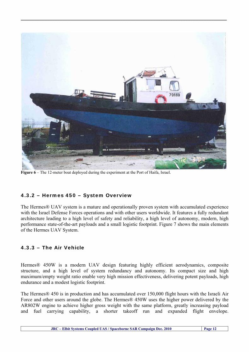
__________________________________________________________________________________
JRC ndash Elbit Systems Coupled UAS Spaceborne SAR Campaign Dec 2010 Page 12
Figure 6 ndash The 12-meter boat deployed during the experiment at the Port of Haifa Israel 432 ndash Hermes 450 ndash System Overview The Hermesreg UAV system is a mature and operationally proven system with accumulated experience with the Israel Defense Forces operations and with other users worldwide It features a fully redundant architecture leading to a high level of safety and reliability a high level of autonomy modern high performance state-of-the-art payloads and a small logistic footprint Figure 7 shows the main elements of the Hermes UAV System 433 ndash The Air Vehicle Hermesreg 450W is a modern UAV design featuring highly efficient aerodynamics composite structure and a high level of system redundancy and autonomy Its compact size and high maximumempty weight ratio enable very high mission effectiveness delivering potent payloads high endurance and a modest logistic footprint The Hermesreg 450 is in production and has accumulated over 150000 flight hours with the Israeli Air Force and other users around the globe The Hermesreg 450W uses the higher power delivered by the AR802W engine to achieve higher gross weight with the same platform greatly increasing payload and fuel carrying capability a shorter takeoff run and expanded flight envelope
__________________________________________________________________________________
JRC ndash Elbit Systems Coupled UAS Spaceborne SAR Campaign Dec 2010 Page 13
The AR802W engine is a derivative of the AR802 rotary engine with widened rotor and housing The result is a 30 gain in power to nearly 70HP Coupled to an Electronic Fuel Injection system the engine is highly efficient and has improved maintenance figures Following is a summary of the physical characteristics of the Hermes 450W air vehicle is given in Table 2
Table 2 ndash Summary of Hermes 450 main characteristics Physical Characteristics
bull Length 61 m bull Wingspan 105 m bull Fuselage diameter 0508 mm bull Max takeoff weight 550 kg bull Max internal fuel weight (including oil) 115 kg bull Max payload weight 150 kg
Figure 7 ndash Elements of the Hermes UAV System
434 ndash Ground Control Station (GCS) The GCS is a transportable system designed to perform and support all Hermesreg UAV family ground Based activities operational activities These activities include mission planning pre-flight check takeoff and landing UAV flight control mission control payloads and systems control as well as post-mission debriefing An embedded or appended training capability is optional Remote communication of video and telemetry to a C4I center via SATCOM or WAN infrastructure is optional The GCS provides a user friendly comfortable effective and protected environment for carrying out UAV missions
__________________________________________________________________________________
JRC ndash Elbit Systems Coupled UAS Spaceborne SAR Campaign Dec 2010 Page 14
The GCS is housed in a shelter with operator consoles of advanced human engineering design that provide an ergonomic operational environment The shelter is based on the NATO ACE III shelter with a side door As Israelrsquos leading C4I provider Elbit Systems has incorporated Hermesreg GCS advanced C4I capabilities including comprehensive mission planning tactical database management and tactical coordination with supported forces and command elements The Hermesreg GCS is uniquely capable of performing two UAV missions concurrently with two UAVs each of which is controlled via a separate Ground Datalink Terminal (GDT) The Hermesreg GCS requires minimal operating personnel ie mission commander and mission operator
Figure 8 ndash The UAS Hermes 450 Ground Control Station (GCS)
435 ndash The EO Payload The CoMPASS Compact Multi Purpose Advanced Stabilized System is a day and night surveillance system that includes a 3rd generation 3-5 μm zoom FLIR camera a color zoom TV CCD camera and automatic tracking capabilities The CoMPASS enables the following
bull Day and night stabilized LOS observation with capabilities of target detection recognition and identification in various weather conditions
bull Automatic and manual tracking of targets bull Slaving CoMPASS Line of Sight (LOS) to external systems bull LOS information bull Target Laser designationampRanging or only Target Laser Ranging bull Laser Target Marker
__________________________________________________________________________________
JRC ndash Elbit Systems Coupled UAS Spaceborne SAR Campaign Dec 2010 Page 15
CoMPASS the EOIR system for UAV applications is the most advanced payload version of the CoMPASS family featuring reduced weight high degree of modularity and flexibility space-saving packaging and advanced operational and video processing features The CoMPASS based STA Stabilized Turret Assembly is a single LRU housing
bull 3rd generation 3-5 μm FLIR zoom Camera bull Color Zoom TV CCD Camera bull Laser Target Designator bull Laser Target Marker bull Electronic Boards
Figure 9 ndash CoMPASS Stabilized Turret Assembly (STA)
__________________________________________________________________________________
JRC ndash Elbit Systems Coupled UAS Spaceborne SAR Campaign Dec 2010 Page 16
5 ndash Preliminary Data Analysis
51 ndash SAR Satellite Imagery Processing The high resolution spaceborne SAR image was analysed visually because the resolution is good enough to allow visual analysis and the site is too close to the coast which makes automatic processing more difficult and prone to error due to artefacts caused by land targets The Hermes 450 images were also analysed visually
52 ndash Ground Truth Data This section briefly describes the Ground Truth data namely the GPS positions of the boat deployed as target during the experiment a photo of the boat as well as other relevant ground truth data collected
521 ndash GPS coordinates of the boat deployed Table 5 gives the GPS coordinates of the boat deployed during the experiment at the time of the Radarsat-2 satellite overpass Table 3 ndash Ground Truth data collected at the time of the satellite pass (154740 UTC=174740 LT) on 8 December 2010
Date 8 Dec2010 Time 154740 UTC=174740 LT Pass Ascending
SatelliteMode Radarsat-2 Spotlight Polarisation HH
Boats Type Size Latitude Longitude
Elbits 12-meter
Boat
32˚ 51830 N 32deg514980N 32863833deg N
34˚ 57961 E 34deg575766E 34966017deg E
__________________________________________________________________________________
JRC ndash Elbit Systems Coupled UAS Spaceborne SAR Campaign Dec 2010 Page 17
521 ndash HERMES 450 Ground Truth Data Table 4 shows the 12-meter Elbitacutes Boat as detected by the IR sensor of the Hermes 450 Table 4 ndash Hermes 450 Ground Truth Data Date 8 Dec2010 Time 154740 UTC=174740 LT
Platform Hermes 450
UAV Type Size Latitude Longitude
UAV Hermes
450
174730h 3284489947 N
174800h
3285089687 N
174730h 3498564048 E
174800h
3499338667 E
Elbits 12-meter
Boat UAV
Image
32˚ 51830 N 32deg514980N 32863833deg N
34˚ 57961 E 34deg575766E 34966017deg E
53 ndash Weather Conditions and Sea State The weather conditions in Haifa are summarized in Table 5 bellow
Table 5 ndash Wind speed wind direction and Temperature Time (IST) Temp Dew
Point Humidity Pressure Visibility Wind Dir
Wind Speed
Gust Speed Precip Events Conditions
550 PM 210 degC 130 degC 60 1017 hPa - North 111 kmh
31 ms - NA Clear
__________________________________________________________________________________
JRC ndash Elbit Systems Coupled UAS Spaceborne SAR Campaign Dec 2010 Page 18
Figure 10 gives the weather data (Temperature Barometric Pressure Wind Speed and Wind Direction) for Haifa Israel on 8 Dec 2010
Figure 10 ndash Weather data (Temperature Barometric Pressure Wind Speed and Wind Direction) for Haifa Israel on 8 Dec 2010
__________________________________________________________________________________
JRC ndash Elbit Systems Coupled UAS Spaceborne SAR Campaign Dec 2010 Page 19
54 ndash Verification of the Results This section briefly describes the verification of the targets detected in the spaceborne SAR image and in the Hermes 450 UAV using the ground truth data collected during the experiment
541 ndash Overview of the UAV Trajectory and the SAR Imagery Footprint Figure 11 gives an overview of the UAV trajectory the footprint of the SAR imagery and the area of the experiment near the port of Haifa The UAV trajectory is depicted in blue The large red rectangle is the footprint of the TerraSAR-X Stripmap The smaller red rectangle is the footprint of the Radarsat-2 Spotlight image
Figure 11 ndash Google Earth UAV trajectory during the experiment and footprinst of the SAR imagery ordered for the experiment Figure 12 is a zoom in of the previous image which allows a more detailed view of the UAV trajectory and of the port of Haifa Figure 13 is a zoom in of figure 12 It shows in more detail the UAV trajectory during the entire experiment and the port of Haifa in Israel
__________________________________________________________________________________
Figure 12 ndash Zoom in of the previous figure showing a more detailed view of the UAV trajectory and of the port of Haifa in Israel
Figure 13 ndash Zoom in of the previous figure showing a even more detailed view of the UAV trajectory and of the port of Haifa in Israel
JRC ndash Elbit Systems Coupled UAS Spaceborne SAR Campaign Dec 2010 Page 20
__________________________________________________________________________________
JRC ndash Elbit Systems Coupled UAS Spaceborne SAR Campaign Dec 2010 Page 21
542 ndash Targets Detected in the Radarsat-2 Spotlight Image Figure 14 illustrates the position of the Elbitrsquos boat used as target in the experiment at the approximate time of the SAR Satellite pass by 1547 UTC (1747 LT) The small photo of the boat shows the approximate position of the boat The two small planes show the positions of the UAV immediately before and after the SAR Satellite pass
Figure 14 ndash Google Earth positions of the elbitrsquos boat and the UAV (Hermes450) at the approximate time of the SAR Satellite overpass by 174740 UTC Figure 15 shows the corresponding SAR image (Radarsat-2 Spotlight) acquired during the experiment Pins 1 and 2 represent the positions of the UAV before and after the SAR satellite overpass Pin 3 illustrates the position of the Elbitacutes boat deployed at the time of the satellite overpass At this scale the SAR signature of the boat is not distinguishable from the sea clutter background However zooming in the SAR image the SAR signature can clearly be seen as illustrated in figure 12 The SAR image in figure 12 also shows several SAR signatures of large ships in the area at the time of the satellite overpass
__________________________________________________________________________________
JRC ndash Elbit Systems Coupled UAS Spaceborne SAR Campaign Dec 2010 Page 22
Elbit`s Boat
Figure 15 ndash On the background the SAR image with the two UAV positions before and after the satellite overpass (Pin1 and Pin2) and the Elbitacutes Boat position (Pin3) The small window over the SAR image shows a zoom in of the SAR image where the SAR signature of the Elbitacutes Boat can clearly be seen The top right are of the SAR image also shows SAR signatures of several large ships in the area at the time of the SAR satellite overpass Figure 16 shows the corresponding SAR image (Radarsat-2 Spotlight) acquired during the experiment and the UAV IR images of some of the targets Pins 1 and 2 represent the positions of the UAV before and after the SAR satellite overpass Pin 3 illustrates the position of the Elbitacutes boat deployed at the time of the satellite overpass At this scale the SAR signature of the boat is not distinguishable from the sea clutter background However zooming in the SAR image the SAR signature can clearly be seen as illustrated in figure 13 On the top left the UAV IR image of the Elbitrsquos Boat The SAR image in figure 13 also shows several SAR signatures of large ships in the area at the time of the satellite overpass On the centre left the UAV IR image of a large ship On the centre right the UAV IR image of a large ship On the bottom right the UAV IR image of a large ship All the UAV images were acquired at night in complete darkness from altitudes in the order of 5500 meters Nonetheless the quality and detail of the UAV images allows classification of the targets and in some cases the identification As it can be seen the potential of UAV for maritime surveillance is very promising During the experiment the UAV detected all the boats and ships in the area and tracked some of the boatsships to test the tracking capability The capability of detection and tracking targets is a critical capability for maritime surveillance
__________________________________________________________________________________
JRC ndash Elbit Systems Coupled UAS Spaceborne SAR Campaign Dec 2010 Page 23
Elbitacutes Boat
Elbit`s Boat
Figure 16 ndash Zoom-in of figure 15 with the UAV images of some targets On the top left the UAV IR image of the Elbitrsquos Boat On the centre left the UAV IR image of a large ship On the centre right the UAV IR image of a large ship On the bottom right the UAV IR image of a large ship Figure 17 shows a comparison of the SAR and UAV images with an optical photo taken in Haifa Israel a couple of hours before the SAR satellites overpass Most of the large ships were detected in the SAR image and some of these ships can be identified in the optical photo Some of the ships in the photo left the area before the SAR satellites overpass
__________________________________________________________________________________
JRC ndash Elbit Systems Coupled UAS Spaceborne SAR Campaign Dec 2010 Page 24
Figure 17 ndash Photo taken in Haifa Israel a couple of hours before the SAR satellites overpass This phot shows the large ships moored in the area Most of these large ships were detected in the Radarsat-2 image As expected their positions and orientations were slightly different at the time of the satellite overpass
Elbitacutes Boat
Elbit`s Boat
__________________________________________________________________________________
JRC ndash Elbit Systems Coupled UAS Spaceborne SAR Campaign Dec 2010 Page 25
Figure 18 ndash Photo taken in Haifa Israel a couple of hours before the SAR satellites overpass This phot shows the large ships moored in the area Most of these large ships were detected in the Radarsat-2 image As expected their positions and orientations were slightly different at the time of the satellite overpass Figure 18 illustrates the SAR image and the corresponding google earth image of a small pier in the port of Haifa In the SAR image due to several artefacts it is not possible to detect the 7 small boats moored to the small pier The UAR IR image of the same area clearly shows the 7 small boats with impressive detail taking into account that the image was acquired from an altitude of about 5500 meters A zoom in of the same UAV IR image is shown in figure 19 As it can be seen although the image was acquired from an altitude of about 5500 meters the 7 small boats can be clearly seen with enough detail to allow classification of the type of boat A UAV flight at lower altitude would probably giver a lot more detail and eventually allow the identification of the small boats
__________________________________________________________________________________
JRC ndash Elbit Systems Coupled UAS Spaceborne SAR Campaign Dec 2010 Page 26
Figure 19 ndash UAV IR image of a small pier in the port of Haifa Israel where 7 small boats can be seen with enough detail to allow classification This image was acquired from an altitude of about 5500 meters in the dark
__________________________________________________________________________________
55 ndash Quantitative Analysis of the Spaceborne SAR Image In order to allow a quantitative analysis of the data the spaceborne SAR image was calibrated using ESArsquos NEST software package version 4B The input was the SAR image acquired and the output was the Radiometric Calibration (Sigma Naught (σdeg)) expressed in terms of intensity and in decibel (dB) the Radar Brightness (βdeg) and the Radiometric Normalisation (gamma naught (γdeg))
551 ndash Radarsat-2-Spotlight 08Dec2010 (154740 UTC) Haifa Israel Figure 20 illustrates the Intensity band of a subset of the Radarsat-2Spotlgiht image (08Dec2010)
Figure 20 ndash Radarsat-2 Spotlgiht image (08Dec2010) ndash Sigma Naught (Intensity) band
JRC ndash Elbit Systems Coupled UAS Spaceborne SAR Campaign Dec 2010 Page 27
__________________________________________________________________________________
Figure 21 illustrates the Sigma Naught Coefficient of the Radarsat-2 Spotlgiht image (08Dec2010) expressed in terms of intensity and decibel (dB)
Figure 21 ndash Radarsat-2 Spotlgiht image (08Dec2010) - On the left the Sigma Naught (σdeg) (intensity) and on the right the Sigma Naught (σdeg) (dB)
ormalisation amma Naught (γdeg)) of the Radarsat-2 Spotlgiht image (08Dec2010) expressed in dB
-2 Spotlgiht image (08Dec2010) - On the left the Beta Naught (βdeg) and on the right the Gamma Naught (γdeg) (dB)
Figure 22 illustrates the Radar Brightness (Beta Naught (βdeg)) and the radiometric n(G
Figure 22 ndash Radarsat
JRC ndash Elbit Systems Coupled UAS Spaceborne SAR Campaign Dec 2010 Page 28
__________________________________________________________________________________ Figure 23 shows the Sigma Naught (σdeg) in dB after some colour manipulation and the histogram of the Sigma Naught (σdeg) image
Figure 23 ndash Radarsat-2 Spotlgiht image (08Dec2010) - On the top left the Sigma Naught (σdeg) after colour manipulation to enhance the targets and on the top right the corresponding histogram On the bottom we can see the histogram of the image
Table 6 gives the statistics of the Sigma Naught (σdeg) Radarsat-2 Spotlgiht image (08Dec2010) The Sigma Naught (σdeg) range from -72897 dB up to 23465 dB The Mean value is -16855 dB the Median is -16594 dB and the standard deviation is 7077 dB
JRC ndash Elbit Systems Coupled UAS Spaceborne SAR Campaign Dec 2010 Page 29
__________________________________________________________________________________
JRC ndash Elbit Systems Coupled UAS Spaceborne SAR Campaign Dec 2010 Page 30
Table 6 ndash Statistics of the Radarsat-2 Spotlgiht image (08Dec2010) (154740 UTC)
Statistics Values Unit Only ROI-Mask pixels considered Number of pixels total Number of considered pixels Ratio of considered pixels
No 322394283 322394283
1000
Minimum Maximum
-728974609375 234655818939209
intensity_db intensity_db
Mean Median Std-Dev Coefficient of Variation
-16855686580177853 -1659462338617847 707796800831575
07888765273432338
intensity_db intensity_db intensity_db intensity_db
Checking the radar backscattering coefficient of some targets (small boat and some large ships) detected in the Radarsat-2 Spotlight image we get values ranging from -0379 dB up to 23455 dB The analysis of the Sigma Naught values (σdeg) of the targets and the area around the targets shows a significant contrast
56 ndash Summary of the Preliminary Analysis of the Spaceborne SAR Image This experiment involved two spaceborne SAR images namely a TerraSAR-X Stripmap and one Radarsat-2 Spotlight The TerraSAR-X image was not delivered by DLR due to technical problems The Elbitrsquos boat deployed during the experiment was detected in the Radarsat-2 Spotlight image Several other targets including a set of large ships were also detected Table 7 summarises the characteristics of the SAR image acquired and the targets detected
Table 7 ndash List of SAR Satellite Images acquired during the experiment and detected boats ISRAEL (HAIFA)
Date Time Place Satellite Mode Ground Truth Data Detected Boats
08Dec2010 (PM) Haifa - Israel Radarsat-2 Spotlight GPSPhotosMovies 1 small boat deployed + 9 large ships
Table 8 gives the minimum and maximum Sigma Naught (σdeg) of the targets detected in each SAR image
Table 8 ndash Minimum and maximum Sigma Naught (σdeg) of the targets detected in each SAR image
Date Time UTC (LT)Pass Satellite Image Mode Polarisation Sigma Naught (σdeg) Min Max
29Oct2010528UTC(728AM LT) DES Radarsat-2 Spotlight HH --0379 dB 23455 dB The SAR signatures of the boats deployed were very weak Some possible reasons to explain such weak signatures are the sea state the wind speed the incidence angle and the type and materials Another possible reason is the processing at DLR
__________________________________________________________________________________
JRC ndash Elbit Systems Coupled UAS Spaceborne SAR Campaign Dec 2010 Page 31
6 ndash Preliminary Conclusions The analysis of the results of this coupled UASSpaceborne SAR experiment shows a promising potential for the use of UAS for maritime surveillance UAS can be integrated into the airborne building block of maritime surveillance systems to complement the existing assets increase system performance and improve the overall maritime domain awareness The main perceived maritime security and safety threats comprise piracy terrorist and military threats weapons proliferationsmuggling drugs trafficking illegal immigration unlawful use of containers attacks to critical infrastructures and illegal fishing The main maritime security and safety gaps include a lack of technologies with the capability of detecting small targets (eg small boats) a lack of wide area and persistent maritime surveillance a lack of coordination and information sharing limited interoperability a lack of containers security a lack of persistent surveillance of critical infrastructures and early warning systems Unmanned Aircraft Systems (UAS) are an emerging technology with strong potential to mitigate the above mentioned threats by filing in the main maritime security and safety gaps listed earlier For instance the wide range of potential applications of UAS to maritime surveillance includes but is not limited to
bull detection classification and identification of small boats bull persistent maritime surveillance bull use as communications relays bull persistent surveillance of critical infrastructures bull early warning systems bull COMINT and ELINT collection etc
Table 11 illustrates the mapping of maritime securitysafety threats vs gaps and summarises the main potential applications of UAS to maritime surveillance The above mentioned potential applications of UAS to the Maritime Domain will be addressed in turn in more detail next bull Detection classification and identification of small boats ndash The capability of detecting classifying and identifying small targets (eg small boats) is among the key technologies required to improve maritime domain awareness This capability is critical to mitigate piracy illegal immigration drugs trafficking weapons smuggling illegal fishing terrorism and critical infrastructure Unmanned Aircraft Systems (UAS) provide this capability more efficiently and at a lower cost than any other existing technology bull Persistent maritime surveillance ndash With the continuous improvements of UAS technologies such as platforms sensors collision avoidance systems command and control systems telecommunications etc UAS are increasing their autonomy endurance and flexibility These characteristics are very important for persistent maritime surveillance UAS can be launched from land ships aircraft and technologies to launch UAS from submarines are currently under development UAS have distinct advantages over other existing technologies for persistent maritime surveillance in terms of autonomyendurance (the Global Surveyor has an autonomy of 1 week) cost (eg as the autonomy of UAS increases the number of staff required to operate UAS decreases) risk (eg if the UAS crashes the crew is not at risk) flexibility (eg they can be launched from a ship reducing the time to reach potential threats) etc
__________________________________________________________________________________
JRC ndash Elbit Systems Coupled UAS Spaceborne SAR Campaign Dec 2010 Page 32
bull Communications relays ndash UAS are being used as communication relays mainly in military context but have the potential to play a similar role in Civil context in several situations such as to replace satellite communications or as a redundant system over any location on Earth The main advantages of using UAS as communication relays is that airborne communication relays mitigate kinetic and noise jamming threats to satellite communications uplinks by providing an alternative set of links either directly to surface-based terminals or to satellites beyond the range of threats They are less susceptible to noise jamming threats than satellites because an adversary has to detect geolocate and track the airborne asset and operate within line of sight of the receive antenna main beam bull Persistent surveillance of critical infrastructures ndash The security of critical infrastructures such as nuclear power plants refineries ports etc requires persistent surveillance UAS can play an important role in providing persistent surveillance over critical infrastructures and over a wide area around the critical infrastructure Some advantages of UAS over other existing technologies such as ground-based assets (eg video cameras alarm systems manned aircraft etc) comprise the security of the UAS (eg hardly can be damaged or switched off as any ground-based asset) the area covered by a UAS (eg it is larger than the area covered by any ground-based asset) the cost (eg UAS is cheaper than manned aircraft with similar capability) etc bull Early warning systems ndash UAS have the potential to be used as part of an integrated system of systems for early warning A UAS can provide information about a given area at a fraction of the cost of alternative means Formation flying of UAS can cover a wide maritime area It is reasonable to assume that in a foreseeable future with the advent of UAS with increased autonomy the operations cost of UAS will likely decrease making them increasingly more attractive bull COMINT and ELINT collection ndash SIGNal INTelligence (SIGNINT) can be divided into two categories namely COMINT and ELINT COMINT stands for Communication Intelligence and ELINT for Electronic Intelligence Collection of COMINT is passive Exploitation of COMINT requires a human operator which implies COMINT UAS are suitable for COMINT and ELINT collection in different scenarios The relatively reduced amount of data collected and analysed during this experiment and the lessons learned do not allow drawing final conclusions about the feasibility of using Unmanned Aerial Systems (UAS) for maritime surveillance However this experiment allowed hands-on experience with UAS technologies and significantly improved the awareness for its applications to maritime surveillance and related issues involved including its potential the feasibility as well as the limiting and enabling factors These different aspects will now be analysed in turn in the next sections Table 11 illustrates the mapping of the main maritime security threats and gaps as well as the main priorities in terms of the different technologies involved in maritime surveillance For each maritime threat the technologies required to fill in each gap is indicated and its priority is expressed in a range of numbers (1 to 3 1 = Maximum Priority 2 = Medium Priority 3 = Low Priority) and colours (Red = Maximum Priority Orange = Medium Priority Green = Low Priority) The main technologies involved in maritime surveillance are listed on the bottom of figure 4 and are reproduced here for convenience of the reader 1- Reporting Systems 2- Sensors 3- Platforms 4- Communications 5- Data Fusion amp Sharing 6- Intelligence and 7- Databases For example the mitigation of the main threat Piracy requires filling in several maritime security gaps (eg lack of persistent surveillance lack of wide-are maritime surveillance lack of small boat detection lack of Early Warning Systems and lack of Information Sharing with maximum priority (1- Red) and among the required technologies listed are UAS LTAAV GEO-HR etc Concerning the remaining two gaps (Limited Interoperability and Containers Security) they are less relevant to mitigate Piracy hence the priority for Limited Interoperability is 2-Orange and for Containers Security is 3- Green
__________________________________________________________________________________ Table 9 ndash The Main Maritime Security and Safety Threats vs Gaps and the technologies that can be used to mitigate them
Maritime Security Main Threats GapsGapsrarr
darrThreats
Lack o f Risk As sessmentCapab ility
La ck of Persiste nt
Surveilla nce
La ck of Wid e-Area su rve illanc e
La ck of Small Boat De tecti on
Lack o f Earl y Warn ing Sys tems
L ack of In forma tion
Sh arin g
L imi ted In terop era bility
Lac k of Co ntai ners
Se cur ity
bull PiracyUAS LTAVG EO-
HR + UAS LT AVGEO-
HR + SAR GEO-HR
+ UAS USV LTAV
+ UAS LTAV
+ Coord in ationamp Sharing +
Inter opera bilityOptimisation +
1 2 3 5 6 7 1 2 3 5 6 7 1 2 3 5 6 1 2 3 123456 4567 1234567 1234567
bull Terro rismUAS LTAVG EO-
HR + UAS L TAV GEO-HR +
SAR AISGEO-HR +
UAS USV LTAV+
Intelligence+
Inte lligen ce+
Inter opera bilityOptimisation +
Intelligence+
1 2 3 5 6 7 1 2 3 5 6 1 2 3 5 6 1 2 3 123456 4567 1234567 1234567
bull Wea pon s ofM ass Dest ru ctio n Smugg ling
UAS LTAVG EO-HR +
UAS LT AVGEO-HR +
SAR AIS+
UAS USV LTAV+
Intelligence+
Inte lligen ce+
Intelligence+
Intelligence+
1 2 3 5 6 7 1 2 3 5 6 1 2 3 5 6 1 2 3 123456 4567 1234567 1234567
bull Drug sTraffic king
UAS LTAVG EO-HR +
UAS LT AVGEO-HR +
SAR AIS+
UAS USV LTAV+
Intelligence+
Inte lligen ce+
Intelligence+
Intelligence+
1 2 3 5 6 7 1 2 3 5 6 1 2 3 5 6 1 2 3 123456 4567 1234567 1234567
bull Illega lImmigratio n
UAS LTAVG EO-HR +
UAS LT AVGEO-HR +
SAR AIS+
UAS USV LTAV+
Intelligence+
Inte lligen ce+
Intelligence+
Intelligence+
1 2 3 5 6 7 1 2 3 5 6 1 2 3 5 6 1 2 3 123456 4567 1234567 1234567
bull Critic alI nfrastruc tureSecu rit y
UAS LTAVG EO-HR +
UAS LT AVGEO-HR +
SAR AIS+
UAS USV LTAV+ + Inte lligen ce
+ Intelligence
+ Intelligence
+
1 2 3 5 6 7 1 2 3 6 1 2 3 5 6 1 2 3 123456 4567 1234567 1234567
bull Illega lFish ing
UAS LTAVG EO-HR +
AI S+SAR UASLTAV +
SAR AIS GEO-HR+
UAS USV LTAV+
Intelligence+
Inte lligen ce+
Intelligence+
1 2 3 5 6 7 1 2 3 5 7 1 2 3 5 6 1 2 3 123456 4567 1234567
bull Un lawf ul Use of Co nta iners
(Secur ity)
UAS LTAVG EO-HR +
GPS Tr acking+
Intelligence+
Inte lligen ce+
GPS Int rusion Det ection Se al
1 2 3 5 6 7 4 6 7 1 2 3 5 6 1 2 3 123456 4567 1234567 1234567
(-) Priority (+) Not Rel evant
SURVEILLANCETECHNOLOGIES
1- Reporti ng Systems
2 -Sensors 3 -P latforms 4 - Communications 5- Data Fusionamp Sharing
6 -I ntelli gence 7 -Databases
JRC ndash Elbit Systems Coupled UAS Spaceborne SAR Campaign Dec 2010 Page 33
__________________________________________________________________________________
JRC ndash Elbit Systems Coupled UAS Spaceborne SAR Campaign Dec 2010 Page 34
61 ndash Hands-on experience with UAS technologies and its applications to maritime surveillance This coupled UASSpaceborne SAR campaign was a unique opportunity to acquire further handsndashon experience with UAS technologies and learn about the main issues related to its applications to maritime surveillance From the planning phase up to the execution of the UAS flight and landing there are several factors that need to be carefully analysed and taken into account A summary of the main issues identified in this experiment is given next 1- Selection of the Experiment Area Authorisation to Fly ndash For the time being UAS can only be flown in restricted areas usually under control of national authorities often the military This is due to the risks that a UAS can pose to human life and property In the present case an area under the authority of the Israeli Civil Aviation Authority was selected The authorisation to fly was not easy to obtain because the selected area is under the authority of the Civil Aviation Authority Figure 24 indicates the area of the experiment in Haifa Israel 2- UAS Communications Issues ndash The Hermes 450 was flown in Line-of-Sight (LOS) since it was close to the coast For BLOS (Beyond Line-of-Sight) operation satellite communications are required 3- Synthetic Aperture Radar (SAR) ndash The specific model Hermes 450W used in the experiment had no SAR sensor installed However a SAR sensor can be installed A SAR sensor is important for maritime surveillance since it allows 247 operations regardless of the weather conditions 4- Automatic Identification System (AIS) Receiver ndash The Hermes 450 used in this experiment was not equipped with an AIS receiver For maritime surveillance operations an AIS receiver is a very important tool since it allows the automatic identification of most ships allowing the UAS to concentrate on non-identified ships
__________________________________________________________________________________
Figure 24 ndash The area of the experiment is indicated by the GPS Trajectory of the UAV
62 ndash Potential of UAS for Maritime Surveillance UAS technologies are relatively recent and involve a wide range of fields spanning from aeronautics and sensors technologies to satellite communications and other engineering disciplines Innovations in each of the fields involved are emerging by the day UAS still have a long way to go before they become mature and their use fully operational For the time being UAS are mainly used for military applications However a large number of non-military UAS applications have been identified by stakeholders and there are several studies and demonstration flights foreseen for the near future Maritime surveillance is one of the most challenging and promising fields of application of UAS The challenges are due to the very demanding conditions under which the UAS must operate over sea and the requirements for safe operation
JRC ndash Elbit Systems Coupled UAS Spaceborne SAR Campaign Dec 2010 Page 35
__________________________________________________________________________________
JRC ndash Elbit Systems Coupled UAS Spaceborne SAR Campaign Dec 2010 Page 36
The present UAS experiment has unveiled some of the potential of UAS for maritime surveillance The UAS tests performed during this experiment include
1 ndash Detection of a Small rubber Boat and a Fishing Ship 2 ndash Tracking of a Small Boat and a Fishing Ship 3 ndash Classification of a Small Boat and a Fishing Ship 4 ndash Identification of a Small Boat and a Fishing Ship 5 ndash Detection and Tracking of People on the Beach
Despite the operational requirement that prevented the UAS from flying bellow 3km the experiment has confirmed the capability of UAS for small boat detection tracking and classification as well as the capability for people detection and tracking Concerning the identification of the targets the characteristics of the images acquired during this mission suggest that flying at lower altitudes the UAS images would allow the identification of the targets The UAS images can be seen from Figure 15 to 20
621 ndash Advantages of UAS for maritime Surveillance Some of the advantages of using UAS for maritime surveillance have been described in the literature and are summarized bellow
1- One potential benefit of UAS is that they could fill in a gap in current maritime surveillance by improving coverage
2- The range of UAS is a significant asset when compared to border agents on patrol or stationary surveillance equipment
3- Eletro-Optical InfraRed (EOIR) sensors (cameras) can identify small size objects from very high altitudes (high resolution)
4- UAS can provide precise and near-real-time imagery to a ground control operator who would then disseminate that information so that informed decisions regarding the deployment of border patrol agents can be made quickly
5- Long endurance UAS used along the border can fly for more than 30 hours up to several days without having to refuel compared with manned helicopterrsquos average flight time of just over 2 hours
6- The ability of UAS to loiter for prolonged periods of time has important operational advantages over manned aircraft
7- The longer flight times of UAS means that sustained coverage over a previously exposed area may improve maritime security
8- The range of UAVs is a significant asset when compared to border agents on patrol or stationary surveillance equipment Nevertheless the extended range and endurance of UAVs may lessen the burdens on human resources at the borders
9- UAS accidents do not risk the lives of pilots as do the helicopters and aircraft currently used by Coast Guards for border patrolling
__________________________________________________________________________________
JRC ndash Elbit Systems Coupled UAS Spaceborne SAR Campaign Dec 2010 Page 37
622 ndash Possible Drawbacks of using UAS for maritime Surveillance UAS also have disadvantages some of them are briefly described next
1- There have been concerns regarding the high accident rate of UAS which can be multiple times higher than that of manned aircraft Because UAS technology is still evolving there is less redundancy built into the operating system of UAS than of manned aircraft and until redundant systems are perfected mishap rates are expected to remain high
2- If control systems fail in a manned aircraft a well-trained pilot is better positioned to find the source of the problem because of hisher physical proximity If a UAS encountered a similar system failure or if a UAS landing was attempted during difficult weather conditions the ground control pilot would be at a disadvantage because he or she is removed from the event Unlike a manned pilot the remote pilot would not be able to assess important sensory information such as wind speed
3- Inclement weather conditions can also impinge on a UAS surveillance capability especially UAS equipped with only an EO camera and Forward Looking Infrared Radar (FLIR) because cloudy conditions and high humidity climates can distort the imagery produced by EO and FLIR equipment The effects of extreme climatic or atmospheric conditions on sensors reportedly can be mitigated with the outfit of one synthetic aperture radar (SAR) system and a moving target indicator (MTI) radar However adding SAR and MTI to a UAS platform would increase the costs associated with using UAS
4- Depending on the type of UAS the costs of operating a UAS can be higher than the costs of operating a manned aircraft This is because some types of UAS require a significant amount of logistical support and specialized operator and maintenance training Operating one UAS may require a crew of up to 20 support personnel The high comparative costs of operating some sophisticated types of UAS may be offset somewhat by their comparatively lower unit costs
63 ndash Main Limiting Factors Preventing the Use of UAS Several pre-requisites must be satisfied to render the UAS a viable cost-effective and regulated alternative to existing resources Major civil and commercial market barriers include
Single European Sky Sense and Avoid technologies Command and Control Technologies Reliability Communications (Bandwidth LOS BLOS)
Lack of airspace regulation that covers all types of UAV systems (encompassing lsquosense and avoidrsquo airspace integration and airworthiness issues)
Affordability - price and customization issues (eg commercial off-the-shelf open modular architecture) Lack of efforts to establish joint customer requirements (although this is gradually changing) Liability for civil operation Capacity for payload flexibility Lack of sufficient secure non-military frequencies for civil operation Perceived reliability (eg vehicle attrition rate vs manned aircraft) Operator training issues Recognitioncustomer perception of the UAV market Technology developments for multi-mission capability
__________________________________________________________________________________
64 ndash UAS Key Enabling Technologies Figure 25 illustrates the components of a typical UAV System showing some of the capabilities needed and the enabling technologies required for performing a given mission Any UAV mission involves many capabilities and technologies Due to the depicted system complexity the main key players such as the US Department of Defense (DoD) and other agencies have started to use the term Unmanned Aerial System (UAS) in place of UAV
Figure 25 ndash Unmanned Aerial Vehicle System Enabled by Autonomous Mission Management Reliable Flight Systems Navigation Accurate Systems Terrain Avoidance Power and Propulsion Some UAS key enabling technologies are listed below
Autonomous Mission Management Collision Avoidance Intelligent System Health Monitoring
Reliable Flight Systems Sophisticated Contingency Management Intelligent Data Handling and Processing Over-the-Horizon Communication Network-Centric Communication Open Architecture Power and Propulsion Navigation Accurate System Technology Enhanced Structures
JRC ndash Elbit Systems Coupled UAS Spaceborne SAR Campaign Dec 2010 Page 38
__________________________________________________________________________________
JRC ndash Elbit Systems Coupled UAS Spaceborne SAR Campaign Dec 2010 Page 39
Table 12 gives a more detailed description of other critical technologies for emerging autonomous UAV systems both civil and military Most of the technologies mentioned in Table 12 apply both to civil and military UAV systems Table 10 ndash Key Enabling Technologies (from SG75 study on autonomous systems)
Critical Technologies Decision Making Software
bull Fuzzy-based decision making bull Knowledge-based system bull Case-based reasoning bull Self-learning techniques bull Decision tree evaluation bull ReasoningInferring bull Probabilisticstochastic reasoning
Prediction Algorithms bull Predictive pathintent algorithms bull Short reaction algorithm bull Effectiveness evaluation
Status Assessment Software bull Internal status analysis bull Self-orientation
Situation Analysis Software bull Situation analysis bull Environmental analysis bull External status analysis
Modelling Software bull Air vehicle modelling algorithms bull Sensor modelling algorithms bull Scenario generation bull Threat system modeling bull Attack simulation bull Mission success optimisation model bull Simulation
Sensor Processing Software bull Sensor fusion bull Area of interest identification bull Automatic target recognition
Adaptive and Self-learning Systems bull Failure self-compensation
Attack Planning Software bull Attack plans and tactical alternatives bull Plan change impact identification
Weapon Engagement Procedure Software bull Weapon engagement algorithms
Mission Plan Update Software bull Route planning system bull Payload plan management system bull Mission Success Optimisation model
Path Optimisation Software bull Optimal trajectory planning bull Path Optimisation System
Targeting Software bull Target tracking bull Target prioritisation
Platform Technologies bull Obstacle detection and avoidance (airborne) bull Obstacle detection and avoidance (ground) bull Improved autopilot bull Speech recognition
Figure 26 summarises system element designs needed to transition from current to next-generation autonomous UAV systems for civilian and military UAS
__________________________________________________________________________________
Figure 26 ndash System Element Designs Needed to Transition from Current to Next-Generation Autonomous UAV Systems These new paradigms are a combination of system attributes and technological capabilities For instance the data fusion secure anti-jam and coordinated multi-vehicle control require technological development as well as specific system development to bring full maturity to unmanned systems Finally very small Micro UAVs (MAVs) and relatively large sophisticated UCAV systems are examples of the range of UAVs that are applying the new platforms payloads onboard processing communications etc to create next generation automated UAVs It is with these new platforms payloads etc that both UCAVs and MAV will be able to address similar operational challenges including
Mixed operation with other assets bull Deconfliction collision avoidance C4I integration
Operation over populated areas bull Safety issues Need to reduce reliance on communications bull UCAV ndash countermeasures bull MAV ndash limited size and power bull Limited line of sight environment Need a fully integrated system bull MAV propulsionpower generation still critical bull Operator machine interface critical bull All weather operations bull Survivability
JRC ndash Elbit Systems Coupled UAS Spaceborne SAR Campaign Dec 2010 Page 40
__________________________________________________________________________________
JRC ndash Elbit Systems Coupled UAS Spaceborne SAR Campaign Dec 2010 Page 41
65 ndash Mission Readiness
651 ndash Mission Readiness Summary This section summarises civil UAV mission readiness The purpose of Mission Readiness is to assess the readiness status of the different technologies involved in UAS In the present case this civil UAV mission readiness based on technology maturation forecasts that meet or exceed the desired or required capabilities identified by the user community Figure 27 summarises the mission readiness time forecasts for the different technologies The technologies annotated with an asterisk () are shown within the figure with maturation forecasts based on development targets expressed in the US Department of Defencesrsquo UAV Roadmap document The purpose of the chart is to be able to identify when the capability to fly a particular mission can be expected as a function of time The left-most end is the least probable and the right end the most probable timeframe
Figure 27 ndash Technology Maturation Summaries in Terms of Mission-Derived Capabilities
__________________________________________________________________________________
JRC ndash Elbit Systems Coupled UAS Spaceborne SAR Campaign Dec 2010 Page 42
66 ndash Small Boat Detection in SAR Satellite Imagery The use of spaceborne SAR imagery for small boat detection requires additional small boat detection experiments under different conditions using different methods It is not possible to draw final conclusions based on a limited number of small boat detection experiments which are not representative of the multiple possible scenarios
67 ndash Limitations of current State-of-the-Art SAR Satellite technology The main limitations of current State-of-the-Art spaceborne SAR imagery for maritime surveillance in particular aimed at small boat detection are 1 - SAR satellites repeat cycles do not allow the coverage of the same area at the required time intervals Constellations of SAR satellites could be a solution 2 - The conflict between resolution and image swath High resolution is required to detect small boats However the high resolution images have small swaths Maritime surveillance with high resolution images would require a large number of images to cover wide maritime areas which is very expensive and for the time being technically not feasible Intelligence data can play an important role by indicating an approximate position of suspicious non cooperative targets therefore reducing the surveillance area which can then be imaged using high resolution images 3- Spaceborne high resolution SAR imagery acquisition times are long enough to allow significant motion of the target during the acquisition time degrading the quality of the image Further research efforts are needed to develop new sensors and platforms As far as sensors are concerned shorter integration times are needed to prevent the blurring effect caused by the motion of the targets Regarding the platforms more platforms are needed to allow lower repeat cycles and improved coverage
__________________________________________________________________________________
JRC ndash Elbit Systems Coupled UAS Spaceborne SAR Campaign Dec 2010 Page 43
7 ndash Plans for Future Work The controlled experiments carried out by the EC-JRC together with Elbit Systems in Haifa-Israel comprised the deployment of a UAS (Hermes-450) and one small 12-meter boat A Radarsat-2 Spotlight image was acquired and several images collected by the Hermes-450 The experiment unveiled the potential of UAS for maritime surveillance in particular for detection tracking classification and possible identification of small targets The UAS was able to detect track and classify small targets such as small boats For low UAS altitude flights identification may be possible in some cases The small 12-meter boat was detected in the spaceborne SAR image The small boat detection trials carried out by the JRC were very successful since most small boats deployed during the experiments were detected in different sea states wind speeds and geographical locations The several small boat detection campaigns conducted by the EC-JRC seem to suggest that the probability of detection of small boats in spaceborne SAR images strongly depends on factors such as the sea state the wind speed the type of boat (shape and materials) the weather conditions among other factors The results of the experiments conducted thus far are not enough to draw final conclusions about the feasibility of using spaceborne SAR imagery for small boat detection However the experiments have an overall positive outcome because they indicate that under suitable sea state and wind speed conditions it is possible to detect small boats using spaceborne SAR The estimation of the probability of detection of small boats in spaceborne SAR images requires a large number of experiments under different circumstances (eg sea state wind speed characteristics of the targets image type and mode etc) Future plans include additional UAS experiments to asses its potential for maritime surveillance
Acknowledgements ndash The authors would like to express their gratitude to Elbit Systems for their cooperation logistical support and assets deployed without which the present coupled UASSAR Satellite Small Boat Detection Campaign would have not been possible
__________________________________________________________________________________
JRC ndash Elbit Systems Coupled UAS Spaceborne SAR Campaign Dec 2010 Page 44
REFERENCES [1] Elbit Systems ldquoUAV Elbit Systems Proposal for Unmanned Aerial Vehicle (UAV) flight to
collect Ground Truth data during a Maritime Surveillance Campaign and demonstrate UAV capabilities for Maritime Surveillancerdquo 2010
[2] ndash Cheryl Yuhas Suborbital Science Program Manager NASA Science Mission Directorate ldquoEarth Observations and the Role of UAVs A Capabilities Assessment Version 11rdquo Civil UAV Assessment Team httpwwwnasagovcentersdrydenresearchcivuavindexhtml August 2006
[3] ndash Document NIAG (SG75) NATO Industrial Advisory Group Study Group 75 Pre-Feasibility Study on UAV Autonomous Operations 2004
[4] ndash United States Department of Defence (DoD) Directive 50001 ldquoThe Defense Acquisition Systemrdquo and DoD Instruction 50002 ldquoOperation of the Defense Acquisition Systemrdquo
[5] ndash Mr James Ramage Mr Massimo Avalle Dr Erik Berglund Dr Luigi Crovella Mr Robert Frampton Dr Uwe Krogmann Mr Christian Ravat Mr Mike Robinson Dr Axel Schulte Dr Scott Wood ldquoRTO-TR-SCI-118 - Automation Technologies and Application Considerations for Highly Integrated Mission Systemsrdquo RTO-TR-SCI-118 AC323(SCI-118)TP204 January 2009
[6] Victor MG Silva Gilles Jurquet Gabriel Marchalot Maria TG Calzado Txema Soroa Juan Sancho Adam Koubek Harm Greidanus and Claudio Savarino ldquoWide Maritime Area Airborne Surveillance (WIMA2S) WP5 Final Reportrdquo WIMAAS WP5 FP7 Project 2008-2011 - ISBN-978-92-79-22801-8 (print) 978-92-79-22802-5 (PDF) ISSN-1018-5593 (print) 1831-9424 (online) EC-JRC Scientific Report JRC 70093 2012
[7] Victor MG Silva and Harm Greidanus ldquoSpaceborne SAR Small Boat Detection Campaign in Portugal and Spainrdquo EUR 25281 EN ISBN 978-92-79-22553-6 ISSN 1831-9424 (online) EC-JRC Scientific Report JRC68160 2012
[8] Goncalves Da Silva V Van Wimersma Greidanus H Hejmanowska B Loudjani P ldquoUAS Applications With Societal Benefits ndash JRCrsquos UAS-Related Activitiesrdquo 2011-2012 UAS Yearbook - UAS Unmanned Aircraft Systems - The Global Perspective 9 (9) 2011 p 127-129 JRC66600
[9] Goncalves Da Silva V Van Wimersma Greidanus H ldquoSmall boat detection using TerraSAR-X and Radarsat2 satellite imageryrdquo 4th TerraSAR-X Science Team Meeting 14 February 2011 DLR Oberpfaffenhofen (Germany) German Aerospace Center (DLR) (Organiser) 2011 JRC63663
[10] V Silva Harm Greidanus ldquoJRC - SAR Satellite Small Boat Detection Campaign - Portoroz ndash Sloveniardquo - ISBN-13 978-92-79-21476-9 ISSN (online) 1831-9424 EC-JRC Scientific Report JRC66835 2011
[11] V Silva Harm Greidanus ldquoJRC - SAR satellite small boat detection campaign - Algarve Portugalrdquo - ISBN-13 978-92-79-21265-9 ISSN (online) 1831-9424 ISSN (print) 1018-5593 EC-JRC Scientific Report JRC66631 2011
[12] ndash Goncalves Da Silva V Van Wimersma Greidanus H ldquoJRC-Frontex Spaceborne SAR Small Boat Detection Campaign ndash Italy amp Spainrdquo - ISBN-13 978-92-79-22213-9 ISSN (online) 1831-9424 EC-JRC Scientific Report JRC67517 2011
[13] - PW Vachon SJ Thomas J Cranton HR Edel and MD Henschel Validation of ship detection by the RADARSAT synthetic aperture radar and the Ocean Monitoring Workstation Canadian Journal of Remote Sensing 26(3)200ndash212 2000
[14] - Crisp D (2004) The state-of-the-art in ship detection in Synthetic Aperture Radar imagery DSTO Information Sciences Laboratory Australia
[15] - Joint Research Centre (JRC) of the European Community mdash IMPAST and DECLIMS web site httpintelligencejrcceceuintmarinefishindexhtm
[16] - McCandless SW Jackson CR (2004) Principles of Synthetic Aperture Radar Synthetic Aperture Radar Marine Users Manual NOAA Washington pp 1-23
[17] - Greidanus H (2008) Satellite Imaging for Maritime Surveillance of the European Seas Remote Sensing of the European Seas 343-358
European Commission
EUR 25346 EN --- Joint Research Centre --- Institute for the Protection and Security of the Citizen
Title JRC --- Elbit Systems Coupled UAS and Spaceborne SAR Campaign in Israel
Authors Victor MG Silva Harm Greidanus
Luxembourg Publications Office of the European Union
2012 --- v+44 pp --- 210 x 297 cm
EUR --- Scientific and Technical Research series --- ISSN 181-9424 (online) ISSN 1018-5593 (print)
ISBN 978-92-79-25020-0
doi10278828527
Abstract The European maritime area is one of Europersquos most important assets with regard to resources security and ultimately
prosperity of the Member States A significant part of Europersquos economy relies directly or indirectly on it It is not just the
shipping or fisheries industries and their related activities It is also shipbuilding and ports marine equipment and offshore
energy maritime and coastal tourism aquaculture submarine telecommunications blue biotech and the protection of the
marine environment The European maritime area faces several risks and threats posed by unlawful activities such as drugs
trafficking smuggling illegal immigration organised crime and terrorism Piracy in international waters also constitutes a threat
to Europe since it can disrupt the maritime transport chain These risks and threats can endanger human lives marine resources
and the environment as well as significantly disrupt the transport chain and global and local security It is anticipated that these
risks and threats will endure in the mid and long run In order to keep Europe as a world leader in the global maritime economy
an effective integratedinteroperable sustainable maritime surveillance system and situational awareness are needed
A significant number of unlawful maritime activities such as illegal immigration drugs trafficking smuggling piracy and
terrorism involve mainly small boats because small boats are faster and more difficult to detect using conventional means
Hence it is very important to find out the feasibility of using Unmanned Aerial Systems (UAS) for small boat detection tracking
classification and identification as well as to study the potential of UAS for maritime surveillance Since 2010 the EC-JRC has
carried out a number of UAS maritime surveillance campaigns to study the potential of UAS for maritime surveillance in
particular for small boat detection This report presents the results and conclusions of the JRC --- Elbit Systems Coupled UAS and
Spaceborne SAR campaign carried out in Dec 2010 in Haifa Israel
As the Commissionrsquos in-house science service the Joint Research Centrersquos mission is to provide EU policies with independent evidence-based scientific and technical support throughout the whole policy cycle Working in close cooperation with policy Directorates-General the JRC addresses key societal challenges while stimulating innovation through developing new standards methods and tools and sharing and transferring its know-how to the Member States and international community Key policy areas include environment and climate change energy and transport agriculture and food security health and consumer protection information society and digital agenda safety and security including nuclear all supported through a cross-cutting and multi-disciplinary approach
LB-NA-25346-EN
-N
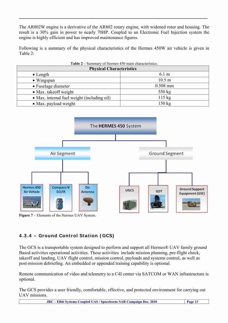
__________________________________________________________________________________
JRC ndash Elbit Systems Coupled UAS Spaceborne SAR Campaign Dec 2010 Page 13
The AR802W engine is a derivative of the AR802 rotary engine with widened rotor and housing The result is a 30 gain in power to nearly 70HP Coupled to an Electronic Fuel Injection system the engine is highly efficient and has improved maintenance figures Following is a summary of the physical characteristics of the Hermes 450W air vehicle is given in Table 2
Table 2 ndash Summary of Hermes 450 main characteristics Physical Characteristics
bull Length 61 m bull Wingspan 105 m bull Fuselage diameter 0508 mm bull Max takeoff weight 550 kg bull Max internal fuel weight (including oil) 115 kg bull Max payload weight 150 kg
Figure 7 ndash Elements of the Hermes UAV System
434 ndash Ground Control Station (GCS) The GCS is a transportable system designed to perform and support all Hermesreg UAV family ground Based activities operational activities These activities include mission planning pre-flight check takeoff and landing UAV flight control mission control payloads and systems control as well as post-mission debriefing An embedded or appended training capability is optional Remote communication of video and telemetry to a C4I center via SATCOM or WAN infrastructure is optional The GCS provides a user friendly comfortable effective and protected environment for carrying out UAV missions
__________________________________________________________________________________
JRC ndash Elbit Systems Coupled UAS Spaceborne SAR Campaign Dec 2010 Page 14
The GCS is housed in a shelter with operator consoles of advanced human engineering design that provide an ergonomic operational environment The shelter is based on the NATO ACE III shelter with a side door As Israelrsquos leading C4I provider Elbit Systems has incorporated Hermesreg GCS advanced C4I capabilities including comprehensive mission planning tactical database management and tactical coordination with supported forces and command elements The Hermesreg GCS is uniquely capable of performing two UAV missions concurrently with two UAVs each of which is controlled via a separate Ground Datalink Terminal (GDT) The Hermesreg GCS requires minimal operating personnel ie mission commander and mission operator
Figure 8 ndash The UAS Hermes 450 Ground Control Station (GCS)
435 ndash The EO Payload The CoMPASS Compact Multi Purpose Advanced Stabilized System is a day and night surveillance system that includes a 3rd generation 3-5 μm zoom FLIR camera a color zoom TV CCD camera and automatic tracking capabilities The CoMPASS enables the following
bull Day and night stabilized LOS observation with capabilities of target detection recognition and identification in various weather conditions
bull Automatic and manual tracking of targets bull Slaving CoMPASS Line of Sight (LOS) to external systems bull LOS information bull Target Laser designationampRanging or only Target Laser Ranging bull Laser Target Marker
__________________________________________________________________________________
JRC ndash Elbit Systems Coupled UAS Spaceborne SAR Campaign Dec 2010 Page 15
CoMPASS the EOIR system for UAV applications is the most advanced payload version of the CoMPASS family featuring reduced weight high degree of modularity and flexibility space-saving packaging and advanced operational and video processing features The CoMPASS based STA Stabilized Turret Assembly is a single LRU housing
bull 3rd generation 3-5 μm FLIR zoom Camera bull Color Zoom TV CCD Camera bull Laser Target Designator bull Laser Target Marker bull Electronic Boards
Figure 9 ndash CoMPASS Stabilized Turret Assembly (STA)
__________________________________________________________________________________
JRC ndash Elbit Systems Coupled UAS Spaceborne SAR Campaign Dec 2010 Page 16
5 ndash Preliminary Data Analysis
51 ndash SAR Satellite Imagery Processing The high resolution spaceborne SAR image was analysed visually because the resolution is good enough to allow visual analysis and the site is too close to the coast which makes automatic processing more difficult and prone to error due to artefacts caused by land targets The Hermes 450 images were also analysed visually
52 ndash Ground Truth Data This section briefly describes the Ground Truth data namely the GPS positions of the boat deployed as target during the experiment a photo of the boat as well as other relevant ground truth data collected
521 ndash GPS coordinates of the boat deployed Table 5 gives the GPS coordinates of the boat deployed during the experiment at the time of the Radarsat-2 satellite overpass Table 3 ndash Ground Truth data collected at the time of the satellite pass (154740 UTC=174740 LT) on 8 December 2010
Date 8 Dec2010 Time 154740 UTC=174740 LT Pass Ascending
SatelliteMode Radarsat-2 Spotlight Polarisation HH
Boats Type Size Latitude Longitude
Elbits 12-meter
Boat
32˚ 51830 N 32deg514980N 32863833deg N
34˚ 57961 E 34deg575766E 34966017deg E
__________________________________________________________________________________
JRC ndash Elbit Systems Coupled UAS Spaceborne SAR Campaign Dec 2010 Page 17
521 ndash HERMES 450 Ground Truth Data Table 4 shows the 12-meter Elbitacutes Boat as detected by the IR sensor of the Hermes 450 Table 4 ndash Hermes 450 Ground Truth Data Date 8 Dec2010 Time 154740 UTC=174740 LT
Platform Hermes 450
UAV Type Size Latitude Longitude
UAV Hermes
450
174730h 3284489947 N
174800h
3285089687 N
174730h 3498564048 E
174800h
3499338667 E
Elbits 12-meter
Boat UAV
Image
32˚ 51830 N 32deg514980N 32863833deg N
34˚ 57961 E 34deg575766E 34966017deg E
53 ndash Weather Conditions and Sea State The weather conditions in Haifa are summarized in Table 5 bellow
Table 5 ndash Wind speed wind direction and Temperature Time (IST) Temp Dew
Point Humidity Pressure Visibility Wind Dir
Wind Speed
Gust Speed Precip Events Conditions
550 PM 210 degC 130 degC 60 1017 hPa - North 111 kmh
31 ms - NA Clear
__________________________________________________________________________________
JRC ndash Elbit Systems Coupled UAS Spaceborne SAR Campaign Dec 2010 Page 18
Figure 10 gives the weather data (Temperature Barometric Pressure Wind Speed and Wind Direction) for Haifa Israel on 8 Dec 2010
Figure 10 ndash Weather data (Temperature Barometric Pressure Wind Speed and Wind Direction) for Haifa Israel on 8 Dec 2010
__________________________________________________________________________________
JRC ndash Elbit Systems Coupled UAS Spaceborne SAR Campaign Dec 2010 Page 19
54 ndash Verification of the Results This section briefly describes the verification of the targets detected in the spaceborne SAR image and in the Hermes 450 UAV using the ground truth data collected during the experiment
541 ndash Overview of the UAV Trajectory and the SAR Imagery Footprint Figure 11 gives an overview of the UAV trajectory the footprint of the SAR imagery and the area of the experiment near the port of Haifa The UAV trajectory is depicted in blue The large red rectangle is the footprint of the TerraSAR-X Stripmap The smaller red rectangle is the footprint of the Radarsat-2 Spotlight image
Figure 11 ndash Google Earth UAV trajectory during the experiment and footprinst of the SAR imagery ordered for the experiment Figure 12 is a zoom in of the previous image which allows a more detailed view of the UAV trajectory and of the port of Haifa Figure 13 is a zoom in of figure 12 It shows in more detail the UAV trajectory during the entire experiment and the port of Haifa in Israel
__________________________________________________________________________________
Figure 12 ndash Zoom in of the previous figure showing a more detailed view of the UAV trajectory and of the port of Haifa in Israel
Figure 13 ndash Zoom in of the previous figure showing a even more detailed view of the UAV trajectory and of the port of Haifa in Israel
JRC ndash Elbit Systems Coupled UAS Spaceborne SAR Campaign Dec 2010 Page 20
__________________________________________________________________________________
JRC ndash Elbit Systems Coupled UAS Spaceborne SAR Campaign Dec 2010 Page 21
542 ndash Targets Detected in the Radarsat-2 Spotlight Image Figure 14 illustrates the position of the Elbitrsquos boat used as target in the experiment at the approximate time of the SAR Satellite pass by 1547 UTC (1747 LT) The small photo of the boat shows the approximate position of the boat The two small planes show the positions of the UAV immediately before and after the SAR Satellite pass
Figure 14 ndash Google Earth positions of the elbitrsquos boat and the UAV (Hermes450) at the approximate time of the SAR Satellite overpass by 174740 UTC Figure 15 shows the corresponding SAR image (Radarsat-2 Spotlight) acquired during the experiment Pins 1 and 2 represent the positions of the UAV before and after the SAR satellite overpass Pin 3 illustrates the position of the Elbitacutes boat deployed at the time of the satellite overpass At this scale the SAR signature of the boat is not distinguishable from the sea clutter background However zooming in the SAR image the SAR signature can clearly be seen as illustrated in figure 12 The SAR image in figure 12 also shows several SAR signatures of large ships in the area at the time of the satellite overpass
__________________________________________________________________________________
JRC ndash Elbit Systems Coupled UAS Spaceborne SAR Campaign Dec 2010 Page 22
Elbit`s Boat
Figure 15 ndash On the background the SAR image with the two UAV positions before and after the satellite overpass (Pin1 and Pin2) and the Elbitacutes Boat position (Pin3) The small window over the SAR image shows a zoom in of the SAR image where the SAR signature of the Elbitacutes Boat can clearly be seen The top right are of the SAR image also shows SAR signatures of several large ships in the area at the time of the SAR satellite overpass Figure 16 shows the corresponding SAR image (Radarsat-2 Spotlight) acquired during the experiment and the UAV IR images of some of the targets Pins 1 and 2 represent the positions of the UAV before and after the SAR satellite overpass Pin 3 illustrates the position of the Elbitacutes boat deployed at the time of the satellite overpass At this scale the SAR signature of the boat is not distinguishable from the sea clutter background However zooming in the SAR image the SAR signature can clearly be seen as illustrated in figure 13 On the top left the UAV IR image of the Elbitrsquos Boat The SAR image in figure 13 also shows several SAR signatures of large ships in the area at the time of the satellite overpass On the centre left the UAV IR image of a large ship On the centre right the UAV IR image of a large ship On the bottom right the UAV IR image of a large ship All the UAV images were acquired at night in complete darkness from altitudes in the order of 5500 meters Nonetheless the quality and detail of the UAV images allows classification of the targets and in some cases the identification As it can be seen the potential of UAV for maritime surveillance is very promising During the experiment the UAV detected all the boats and ships in the area and tracked some of the boatsships to test the tracking capability The capability of detection and tracking targets is a critical capability for maritime surveillance
__________________________________________________________________________________
JRC ndash Elbit Systems Coupled UAS Spaceborne SAR Campaign Dec 2010 Page 23
Elbitacutes Boat
Elbit`s Boat
Figure 16 ndash Zoom-in of figure 15 with the UAV images of some targets On the top left the UAV IR image of the Elbitrsquos Boat On the centre left the UAV IR image of a large ship On the centre right the UAV IR image of a large ship On the bottom right the UAV IR image of a large ship Figure 17 shows a comparison of the SAR and UAV images with an optical photo taken in Haifa Israel a couple of hours before the SAR satellites overpass Most of the large ships were detected in the SAR image and some of these ships can be identified in the optical photo Some of the ships in the photo left the area before the SAR satellites overpass
__________________________________________________________________________________
JRC ndash Elbit Systems Coupled UAS Spaceborne SAR Campaign Dec 2010 Page 24
Figure 17 ndash Photo taken in Haifa Israel a couple of hours before the SAR satellites overpass This phot shows the large ships moored in the area Most of these large ships were detected in the Radarsat-2 image As expected their positions and orientations were slightly different at the time of the satellite overpass
Elbitacutes Boat
Elbit`s Boat
__________________________________________________________________________________
JRC ndash Elbit Systems Coupled UAS Spaceborne SAR Campaign Dec 2010 Page 25
Figure 18 ndash Photo taken in Haifa Israel a couple of hours before the SAR satellites overpass This phot shows the large ships moored in the area Most of these large ships were detected in the Radarsat-2 image As expected their positions and orientations were slightly different at the time of the satellite overpass Figure 18 illustrates the SAR image and the corresponding google earth image of a small pier in the port of Haifa In the SAR image due to several artefacts it is not possible to detect the 7 small boats moored to the small pier The UAR IR image of the same area clearly shows the 7 small boats with impressive detail taking into account that the image was acquired from an altitude of about 5500 meters A zoom in of the same UAV IR image is shown in figure 19 As it can be seen although the image was acquired from an altitude of about 5500 meters the 7 small boats can be clearly seen with enough detail to allow classification of the type of boat A UAV flight at lower altitude would probably giver a lot more detail and eventually allow the identification of the small boats
__________________________________________________________________________________
JRC ndash Elbit Systems Coupled UAS Spaceborne SAR Campaign Dec 2010 Page 26
Figure 19 ndash UAV IR image of a small pier in the port of Haifa Israel where 7 small boats can be seen with enough detail to allow classification This image was acquired from an altitude of about 5500 meters in the dark
__________________________________________________________________________________
55 ndash Quantitative Analysis of the Spaceborne SAR Image In order to allow a quantitative analysis of the data the spaceborne SAR image was calibrated using ESArsquos NEST software package version 4B The input was the SAR image acquired and the output was the Radiometric Calibration (Sigma Naught (σdeg)) expressed in terms of intensity and in decibel (dB) the Radar Brightness (βdeg) and the Radiometric Normalisation (gamma naught (γdeg))
551 ndash Radarsat-2-Spotlight 08Dec2010 (154740 UTC) Haifa Israel Figure 20 illustrates the Intensity band of a subset of the Radarsat-2Spotlgiht image (08Dec2010)
Figure 20 ndash Radarsat-2 Spotlgiht image (08Dec2010) ndash Sigma Naught (Intensity) band
JRC ndash Elbit Systems Coupled UAS Spaceborne SAR Campaign Dec 2010 Page 27
__________________________________________________________________________________
Figure 21 illustrates the Sigma Naught Coefficient of the Radarsat-2 Spotlgiht image (08Dec2010) expressed in terms of intensity and decibel (dB)
Figure 21 ndash Radarsat-2 Spotlgiht image (08Dec2010) - On the left the Sigma Naught (σdeg) (intensity) and on the right the Sigma Naught (σdeg) (dB)
ormalisation amma Naught (γdeg)) of the Radarsat-2 Spotlgiht image (08Dec2010) expressed in dB
-2 Spotlgiht image (08Dec2010) - On the left the Beta Naught (βdeg) and on the right the Gamma Naught (γdeg) (dB)
Figure 22 illustrates the Radar Brightness (Beta Naught (βdeg)) and the radiometric n(G
Figure 22 ndash Radarsat
JRC ndash Elbit Systems Coupled UAS Spaceborne SAR Campaign Dec 2010 Page 28
__________________________________________________________________________________ Figure 23 shows the Sigma Naught (σdeg) in dB after some colour manipulation and the histogram of the Sigma Naught (σdeg) image
Figure 23 ndash Radarsat-2 Spotlgiht image (08Dec2010) - On the top left the Sigma Naught (σdeg) after colour manipulation to enhance the targets and on the top right the corresponding histogram On the bottom we can see the histogram of the image
Table 6 gives the statistics of the Sigma Naught (σdeg) Radarsat-2 Spotlgiht image (08Dec2010) The Sigma Naught (σdeg) range from -72897 dB up to 23465 dB The Mean value is -16855 dB the Median is -16594 dB and the standard deviation is 7077 dB
JRC ndash Elbit Systems Coupled UAS Spaceborne SAR Campaign Dec 2010 Page 29
__________________________________________________________________________________
JRC ndash Elbit Systems Coupled UAS Spaceborne SAR Campaign Dec 2010 Page 30
Table 6 ndash Statistics of the Radarsat-2 Spotlgiht image (08Dec2010) (154740 UTC)
Statistics Values Unit Only ROI-Mask pixels considered Number of pixels total Number of considered pixels Ratio of considered pixels
No 322394283 322394283
1000
Minimum Maximum
-728974609375 234655818939209
intensity_db intensity_db
Mean Median Std-Dev Coefficient of Variation
-16855686580177853 -1659462338617847 707796800831575
07888765273432338
intensity_db intensity_db intensity_db intensity_db
Checking the radar backscattering coefficient of some targets (small boat and some large ships) detected in the Radarsat-2 Spotlight image we get values ranging from -0379 dB up to 23455 dB The analysis of the Sigma Naught values (σdeg) of the targets and the area around the targets shows a significant contrast
56 ndash Summary of the Preliminary Analysis of the Spaceborne SAR Image This experiment involved two spaceborne SAR images namely a TerraSAR-X Stripmap and one Radarsat-2 Spotlight The TerraSAR-X image was not delivered by DLR due to technical problems The Elbitrsquos boat deployed during the experiment was detected in the Radarsat-2 Spotlight image Several other targets including a set of large ships were also detected Table 7 summarises the characteristics of the SAR image acquired and the targets detected
Table 7 ndash List of SAR Satellite Images acquired during the experiment and detected boats ISRAEL (HAIFA)
Date Time Place Satellite Mode Ground Truth Data Detected Boats
08Dec2010 (PM) Haifa - Israel Radarsat-2 Spotlight GPSPhotosMovies 1 small boat deployed + 9 large ships
Table 8 gives the minimum and maximum Sigma Naught (σdeg) of the targets detected in each SAR image
Table 8 ndash Minimum and maximum Sigma Naught (σdeg) of the targets detected in each SAR image
Date Time UTC (LT)Pass Satellite Image Mode Polarisation Sigma Naught (σdeg) Min Max
29Oct2010528UTC(728AM LT) DES Radarsat-2 Spotlight HH --0379 dB 23455 dB The SAR signatures of the boats deployed were very weak Some possible reasons to explain such weak signatures are the sea state the wind speed the incidence angle and the type and materials Another possible reason is the processing at DLR
__________________________________________________________________________________
JRC ndash Elbit Systems Coupled UAS Spaceborne SAR Campaign Dec 2010 Page 31
6 ndash Preliminary Conclusions The analysis of the results of this coupled UASSpaceborne SAR experiment shows a promising potential for the use of UAS for maritime surveillance UAS can be integrated into the airborne building block of maritime surveillance systems to complement the existing assets increase system performance and improve the overall maritime domain awareness The main perceived maritime security and safety threats comprise piracy terrorist and military threats weapons proliferationsmuggling drugs trafficking illegal immigration unlawful use of containers attacks to critical infrastructures and illegal fishing The main maritime security and safety gaps include a lack of technologies with the capability of detecting small targets (eg small boats) a lack of wide area and persistent maritime surveillance a lack of coordination and information sharing limited interoperability a lack of containers security a lack of persistent surveillance of critical infrastructures and early warning systems Unmanned Aircraft Systems (UAS) are an emerging technology with strong potential to mitigate the above mentioned threats by filing in the main maritime security and safety gaps listed earlier For instance the wide range of potential applications of UAS to maritime surveillance includes but is not limited to
bull detection classification and identification of small boats bull persistent maritime surveillance bull use as communications relays bull persistent surveillance of critical infrastructures bull early warning systems bull COMINT and ELINT collection etc
Table 11 illustrates the mapping of maritime securitysafety threats vs gaps and summarises the main potential applications of UAS to maritime surveillance The above mentioned potential applications of UAS to the Maritime Domain will be addressed in turn in more detail next bull Detection classification and identification of small boats ndash The capability of detecting classifying and identifying small targets (eg small boats) is among the key technologies required to improve maritime domain awareness This capability is critical to mitigate piracy illegal immigration drugs trafficking weapons smuggling illegal fishing terrorism and critical infrastructure Unmanned Aircraft Systems (UAS) provide this capability more efficiently and at a lower cost than any other existing technology bull Persistent maritime surveillance ndash With the continuous improvements of UAS technologies such as platforms sensors collision avoidance systems command and control systems telecommunications etc UAS are increasing their autonomy endurance and flexibility These characteristics are very important for persistent maritime surveillance UAS can be launched from land ships aircraft and technologies to launch UAS from submarines are currently under development UAS have distinct advantages over other existing technologies for persistent maritime surveillance in terms of autonomyendurance (the Global Surveyor has an autonomy of 1 week) cost (eg as the autonomy of UAS increases the number of staff required to operate UAS decreases) risk (eg if the UAS crashes the crew is not at risk) flexibility (eg they can be launched from a ship reducing the time to reach potential threats) etc
__________________________________________________________________________________
JRC ndash Elbit Systems Coupled UAS Spaceborne SAR Campaign Dec 2010 Page 32
bull Communications relays ndash UAS are being used as communication relays mainly in military context but have the potential to play a similar role in Civil context in several situations such as to replace satellite communications or as a redundant system over any location on Earth The main advantages of using UAS as communication relays is that airborne communication relays mitigate kinetic and noise jamming threats to satellite communications uplinks by providing an alternative set of links either directly to surface-based terminals or to satellites beyond the range of threats They are less susceptible to noise jamming threats than satellites because an adversary has to detect geolocate and track the airborne asset and operate within line of sight of the receive antenna main beam bull Persistent surveillance of critical infrastructures ndash The security of critical infrastructures such as nuclear power plants refineries ports etc requires persistent surveillance UAS can play an important role in providing persistent surveillance over critical infrastructures and over a wide area around the critical infrastructure Some advantages of UAS over other existing technologies such as ground-based assets (eg video cameras alarm systems manned aircraft etc) comprise the security of the UAS (eg hardly can be damaged or switched off as any ground-based asset) the area covered by a UAS (eg it is larger than the area covered by any ground-based asset) the cost (eg UAS is cheaper than manned aircraft with similar capability) etc bull Early warning systems ndash UAS have the potential to be used as part of an integrated system of systems for early warning A UAS can provide information about a given area at a fraction of the cost of alternative means Formation flying of UAS can cover a wide maritime area It is reasonable to assume that in a foreseeable future with the advent of UAS with increased autonomy the operations cost of UAS will likely decrease making them increasingly more attractive bull COMINT and ELINT collection ndash SIGNal INTelligence (SIGNINT) can be divided into two categories namely COMINT and ELINT COMINT stands for Communication Intelligence and ELINT for Electronic Intelligence Collection of COMINT is passive Exploitation of COMINT requires a human operator which implies COMINT UAS are suitable for COMINT and ELINT collection in different scenarios The relatively reduced amount of data collected and analysed during this experiment and the lessons learned do not allow drawing final conclusions about the feasibility of using Unmanned Aerial Systems (UAS) for maritime surveillance However this experiment allowed hands-on experience with UAS technologies and significantly improved the awareness for its applications to maritime surveillance and related issues involved including its potential the feasibility as well as the limiting and enabling factors These different aspects will now be analysed in turn in the next sections Table 11 illustrates the mapping of the main maritime security threats and gaps as well as the main priorities in terms of the different technologies involved in maritime surveillance For each maritime threat the technologies required to fill in each gap is indicated and its priority is expressed in a range of numbers (1 to 3 1 = Maximum Priority 2 = Medium Priority 3 = Low Priority) and colours (Red = Maximum Priority Orange = Medium Priority Green = Low Priority) The main technologies involved in maritime surveillance are listed on the bottom of figure 4 and are reproduced here for convenience of the reader 1- Reporting Systems 2- Sensors 3- Platforms 4- Communications 5- Data Fusion amp Sharing 6- Intelligence and 7- Databases For example the mitigation of the main threat Piracy requires filling in several maritime security gaps (eg lack of persistent surveillance lack of wide-are maritime surveillance lack of small boat detection lack of Early Warning Systems and lack of Information Sharing with maximum priority (1- Red) and among the required technologies listed are UAS LTAAV GEO-HR etc Concerning the remaining two gaps (Limited Interoperability and Containers Security) they are less relevant to mitigate Piracy hence the priority for Limited Interoperability is 2-Orange and for Containers Security is 3- Green
__________________________________________________________________________________ Table 9 ndash The Main Maritime Security and Safety Threats vs Gaps and the technologies that can be used to mitigate them
Maritime Security Main Threats GapsGapsrarr
darrThreats
Lack o f Risk As sessmentCapab ility
La ck of Persiste nt
Surveilla nce
La ck of Wid e-Area su rve illanc e
La ck of Small Boat De tecti on
Lack o f Earl y Warn ing Sys tems
L ack of In forma tion
Sh arin g
L imi ted In terop era bility
Lac k of Co ntai ners
Se cur ity
bull PiracyUAS LTAVG EO-
HR + UAS LT AVGEO-
HR + SAR GEO-HR
+ UAS USV LTAV
+ UAS LTAV
+ Coord in ationamp Sharing +
Inter opera bilityOptimisation +
1 2 3 5 6 7 1 2 3 5 6 7 1 2 3 5 6 1 2 3 123456 4567 1234567 1234567
bull Terro rismUAS LTAVG EO-
HR + UAS L TAV GEO-HR +
SAR AISGEO-HR +
UAS USV LTAV+
Intelligence+
Inte lligen ce+
Inter opera bilityOptimisation +
Intelligence+
1 2 3 5 6 7 1 2 3 5 6 1 2 3 5 6 1 2 3 123456 4567 1234567 1234567
bull Wea pon s ofM ass Dest ru ctio n Smugg ling
UAS LTAVG EO-HR +
UAS LT AVGEO-HR +
SAR AIS+
UAS USV LTAV+
Intelligence+
Inte lligen ce+
Intelligence+
Intelligence+
1 2 3 5 6 7 1 2 3 5 6 1 2 3 5 6 1 2 3 123456 4567 1234567 1234567
bull Drug sTraffic king
UAS LTAVG EO-HR +
UAS LT AVGEO-HR +
SAR AIS+
UAS USV LTAV+
Intelligence+
Inte lligen ce+
Intelligence+
Intelligence+
1 2 3 5 6 7 1 2 3 5 6 1 2 3 5 6 1 2 3 123456 4567 1234567 1234567
bull Illega lImmigratio n
UAS LTAVG EO-HR +
UAS LT AVGEO-HR +
SAR AIS+
UAS USV LTAV+
Intelligence+
Inte lligen ce+
Intelligence+
Intelligence+
1 2 3 5 6 7 1 2 3 5 6 1 2 3 5 6 1 2 3 123456 4567 1234567 1234567
bull Critic alI nfrastruc tureSecu rit y
UAS LTAVG EO-HR +
UAS LT AVGEO-HR +
SAR AIS+
UAS USV LTAV+ + Inte lligen ce
+ Intelligence
+ Intelligence
+
1 2 3 5 6 7 1 2 3 6 1 2 3 5 6 1 2 3 123456 4567 1234567 1234567
bull Illega lFish ing
UAS LTAVG EO-HR +
AI S+SAR UASLTAV +
SAR AIS GEO-HR+
UAS USV LTAV+
Intelligence+
Inte lligen ce+
Intelligence+
1 2 3 5 6 7 1 2 3 5 7 1 2 3 5 6 1 2 3 123456 4567 1234567
bull Un lawf ul Use of Co nta iners
(Secur ity)
UAS LTAVG EO-HR +
GPS Tr acking+
Intelligence+
Inte lligen ce+
GPS Int rusion Det ection Se al
1 2 3 5 6 7 4 6 7 1 2 3 5 6 1 2 3 123456 4567 1234567 1234567
(-) Priority (+) Not Rel evant
SURVEILLANCETECHNOLOGIES
1- Reporti ng Systems
2 -Sensors 3 -P latforms 4 - Communications 5- Data Fusionamp Sharing
6 -I ntelli gence 7 -Databases
JRC ndash Elbit Systems Coupled UAS Spaceborne SAR Campaign Dec 2010 Page 33
__________________________________________________________________________________
JRC ndash Elbit Systems Coupled UAS Spaceborne SAR Campaign Dec 2010 Page 34
61 ndash Hands-on experience with UAS technologies and its applications to maritime surveillance This coupled UASSpaceborne SAR campaign was a unique opportunity to acquire further handsndashon experience with UAS technologies and learn about the main issues related to its applications to maritime surveillance From the planning phase up to the execution of the UAS flight and landing there are several factors that need to be carefully analysed and taken into account A summary of the main issues identified in this experiment is given next 1- Selection of the Experiment Area Authorisation to Fly ndash For the time being UAS can only be flown in restricted areas usually under control of national authorities often the military This is due to the risks that a UAS can pose to human life and property In the present case an area under the authority of the Israeli Civil Aviation Authority was selected The authorisation to fly was not easy to obtain because the selected area is under the authority of the Civil Aviation Authority Figure 24 indicates the area of the experiment in Haifa Israel 2- UAS Communications Issues ndash The Hermes 450 was flown in Line-of-Sight (LOS) since it was close to the coast For BLOS (Beyond Line-of-Sight) operation satellite communications are required 3- Synthetic Aperture Radar (SAR) ndash The specific model Hermes 450W used in the experiment had no SAR sensor installed However a SAR sensor can be installed A SAR sensor is important for maritime surveillance since it allows 247 operations regardless of the weather conditions 4- Automatic Identification System (AIS) Receiver ndash The Hermes 450 used in this experiment was not equipped with an AIS receiver For maritime surveillance operations an AIS receiver is a very important tool since it allows the automatic identification of most ships allowing the UAS to concentrate on non-identified ships
__________________________________________________________________________________
Figure 24 ndash The area of the experiment is indicated by the GPS Trajectory of the UAV
62 ndash Potential of UAS for Maritime Surveillance UAS technologies are relatively recent and involve a wide range of fields spanning from aeronautics and sensors technologies to satellite communications and other engineering disciplines Innovations in each of the fields involved are emerging by the day UAS still have a long way to go before they become mature and their use fully operational For the time being UAS are mainly used for military applications However a large number of non-military UAS applications have been identified by stakeholders and there are several studies and demonstration flights foreseen for the near future Maritime surveillance is one of the most challenging and promising fields of application of UAS The challenges are due to the very demanding conditions under which the UAS must operate over sea and the requirements for safe operation
JRC ndash Elbit Systems Coupled UAS Spaceborne SAR Campaign Dec 2010 Page 35
__________________________________________________________________________________
JRC ndash Elbit Systems Coupled UAS Spaceborne SAR Campaign Dec 2010 Page 36
The present UAS experiment has unveiled some of the potential of UAS for maritime surveillance The UAS tests performed during this experiment include
1 ndash Detection of a Small rubber Boat and a Fishing Ship 2 ndash Tracking of a Small Boat and a Fishing Ship 3 ndash Classification of a Small Boat and a Fishing Ship 4 ndash Identification of a Small Boat and a Fishing Ship 5 ndash Detection and Tracking of People on the Beach
Despite the operational requirement that prevented the UAS from flying bellow 3km the experiment has confirmed the capability of UAS for small boat detection tracking and classification as well as the capability for people detection and tracking Concerning the identification of the targets the characteristics of the images acquired during this mission suggest that flying at lower altitudes the UAS images would allow the identification of the targets The UAS images can be seen from Figure 15 to 20
621 ndash Advantages of UAS for maritime Surveillance Some of the advantages of using UAS for maritime surveillance have been described in the literature and are summarized bellow
1- One potential benefit of UAS is that they could fill in a gap in current maritime surveillance by improving coverage
2- The range of UAS is a significant asset when compared to border agents on patrol or stationary surveillance equipment
3- Eletro-Optical InfraRed (EOIR) sensors (cameras) can identify small size objects from very high altitudes (high resolution)
4- UAS can provide precise and near-real-time imagery to a ground control operator who would then disseminate that information so that informed decisions regarding the deployment of border patrol agents can be made quickly
5- Long endurance UAS used along the border can fly for more than 30 hours up to several days without having to refuel compared with manned helicopterrsquos average flight time of just over 2 hours
6- The ability of UAS to loiter for prolonged periods of time has important operational advantages over manned aircraft
7- The longer flight times of UAS means that sustained coverage over a previously exposed area may improve maritime security
8- The range of UAVs is a significant asset when compared to border agents on patrol or stationary surveillance equipment Nevertheless the extended range and endurance of UAVs may lessen the burdens on human resources at the borders
9- UAS accidents do not risk the lives of pilots as do the helicopters and aircraft currently used by Coast Guards for border patrolling
__________________________________________________________________________________
JRC ndash Elbit Systems Coupled UAS Spaceborne SAR Campaign Dec 2010 Page 37
622 ndash Possible Drawbacks of using UAS for maritime Surveillance UAS also have disadvantages some of them are briefly described next
1- There have been concerns regarding the high accident rate of UAS which can be multiple times higher than that of manned aircraft Because UAS technology is still evolving there is less redundancy built into the operating system of UAS than of manned aircraft and until redundant systems are perfected mishap rates are expected to remain high
2- If control systems fail in a manned aircraft a well-trained pilot is better positioned to find the source of the problem because of hisher physical proximity If a UAS encountered a similar system failure or if a UAS landing was attempted during difficult weather conditions the ground control pilot would be at a disadvantage because he or she is removed from the event Unlike a manned pilot the remote pilot would not be able to assess important sensory information such as wind speed
3- Inclement weather conditions can also impinge on a UAS surveillance capability especially UAS equipped with only an EO camera and Forward Looking Infrared Radar (FLIR) because cloudy conditions and high humidity climates can distort the imagery produced by EO and FLIR equipment The effects of extreme climatic or atmospheric conditions on sensors reportedly can be mitigated with the outfit of one synthetic aperture radar (SAR) system and a moving target indicator (MTI) radar However adding SAR and MTI to a UAS platform would increase the costs associated with using UAS
4- Depending on the type of UAS the costs of operating a UAS can be higher than the costs of operating a manned aircraft This is because some types of UAS require a significant amount of logistical support and specialized operator and maintenance training Operating one UAS may require a crew of up to 20 support personnel The high comparative costs of operating some sophisticated types of UAS may be offset somewhat by their comparatively lower unit costs
63 ndash Main Limiting Factors Preventing the Use of UAS Several pre-requisites must be satisfied to render the UAS a viable cost-effective and regulated alternative to existing resources Major civil and commercial market barriers include
Single European Sky Sense and Avoid technologies Command and Control Technologies Reliability Communications (Bandwidth LOS BLOS)
Lack of airspace regulation that covers all types of UAV systems (encompassing lsquosense and avoidrsquo airspace integration and airworthiness issues)
Affordability - price and customization issues (eg commercial off-the-shelf open modular architecture) Lack of efforts to establish joint customer requirements (although this is gradually changing) Liability for civil operation Capacity for payload flexibility Lack of sufficient secure non-military frequencies for civil operation Perceived reliability (eg vehicle attrition rate vs manned aircraft) Operator training issues Recognitioncustomer perception of the UAV market Technology developments for multi-mission capability
__________________________________________________________________________________
64 ndash UAS Key Enabling Technologies Figure 25 illustrates the components of a typical UAV System showing some of the capabilities needed and the enabling technologies required for performing a given mission Any UAV mission involves many capabilities and technologies Due to the depicted system complexity the main key players such as the US Department of Defense (DoD) and other agencies have started to use the term Unmanned Aerial System (UAS) in place of UAV
Figure 25 ndash Unmanned Aerial Vehicle System Enabled by Autonomous Mission Management Reliable Flight Systems Navigation Accurate Systems Terrain Avoidance Power and Propulsion Some UAS key enabling technologies are listed below
Autonomous Mission Management Collision Avoidance Intelligent System Health Monitoring
Reliable Flight Systems Sophisticated Contingency Management Intelligent Data Handling and Processing Over-the-Horizon Communication Network-Centric Communication Open Architecture Power and Propulsion Navigation Accurate System Technology Enhanced Structures
JRC ndash Elbit Systems Coupled UAS Spaceborne SAR Campaign Dec 2010 Page 38
__________________________________________________________________________________
JRC ndash Elbit Systems Coupled UAS Spaceborne SAR Campaign Dec 2010 Page 39
Table 12 gives a more detailed description of other critical technologies for emerging autonomous UAV systems both civil and military Most of the technologies mentioned in Table 12 apply both to civil and military UAV systems Table 10 ndash Key Enabling Technologies (from SG75 study on autonomous systems)
Critical Technologies Decision Making Software
bull Fuzzy-based decision making bull Knowledge-based system bull Case-based reasoning bull Self-learning techniques bull Decision tree evaluation bull ReasoningInferring bull Probabilisticstochastic reasoning
Prediction Algorithms bull Predictive pathintent algorithms bull Short reaction algorithm bull Effectiveness evaluation
Status Assessment Software bull Internal status analysis bull Self-orientation
Situation Analysis Software bull Situation analysis bull Environmental analysis bull External status analysis
Modelling Software bull Air vehicle modelling algorithms bull Sensor modelling algorithms bull Scenario generation bull Threat system modeling bull Attack simulation bull Mission success optimisation model bull Simulation
Sensor Processing Software bull Sensor fusion bull Area of interest identification bull Automatic target recognition
Adaptive and Self-learning Systems bull Failure self-compensation
Attack Planning Software bull Attack plans and tactical alternatives bull Plan change impact identification
Weapon Engagement Procedure Software bull Weapon engagement algorithms
Mission Plan Update Software bull Route planning system bull Payload plan management system bull Mission Success Optimisation model
Path Optimisation Software bull Optimal trajectory planning bull Path Optimisation System
Targeting Software bull Target tracking bull Target prioritisation
Platform Technologies bull Obstacle detection and avoidance (airborne) bull Obstacle detection and avoidance (ground) bull Improved autopilot bull Speech recognition
Figure 26 summarises system element designs needed to transition from current to next-generation autonomous UAV systems for civilian and military UAS
__________________________________________________________________________________
Figure 26 ndash System Element Designs Needed to Transition from Current to Next-Generation Autonomous UAV Systems These new paradigms are a combination of system attributes and technological capabilities For instance the data fusion secure anti-jam and coordinated multi-vehicle control require technological development as well as specific system development to bring full maturity to unmanned systems Finally very small Micro UAVs (MAVs) and relatively large sophisticated UCAV systems are examples of the range of UAVs that are applying the new platforms payloads onboard processing communications etc to create next generation automated UAVs It is with these new platforms payloads etc that both UCAVs and MAV will be able to address similar operational challenges including
Mixed operation with other assets bull Deconfliction collision avoidance C4I integration
Operation over populated areas bull Safety issues Need to reduce reliance on communications bull UCAV ndash countermeasures bull MAV ndash limited size and power bull Limited line of sight environment Need a fully integrated system bull MAV propulsionpower generation still critical bull Operator machine interface critical bull All weather operations bull Survivability
JRC ndash Elbit Systems Coupled UAS Spaceborne SAR Campaign Dec 2010 Page 40
__________________________________________________________________________________
JRC ndash Elbit Systems Coupled UAS Spaceborne SAR Campaign Dec 2010 Page 41
65 ndash Mission Readiness
651 ndash Mission Readiness Summary This section summarises civil UAV mission readiness The purpose of Mission Readiness is to assess the readiness status of the different technologies involved in UAS In the present case this civil UAV mission readiness based on technology maturation forecasts that meet or exceed the desired or required capabilities identified by the user community Figure 27 summarises the mission readiness time forecasts for the different technologies The technologies annotated with an asterisk () are shown within the figure with maturation forecasts based on development targets expressed in the US Department of Defencesrsquo UAV Roadmap document The purpose of the chart is to be able to identify when the capability to fly a particular mission can be expected as a function of time The left-most end is the least probable and the right end the most probable timeframe
Figure 27 ndash Technology Maturation Summaries in Terms of Mission-Derived Capabilities
__________________________________________________________________________________
JRC ndash Elbit Systems Coupled UAS Spaceborne SAR Campaign Dec 2010 Page 42
66 ndash Small Boat Detection in SAR Satellite Imagery The use of spaceborne SAR imagery for small boat detection requires additional small boat detection experiments under different conditions using different methods It is not possible to draw final conclusions based on a limited number of small boat detection experiments which are not representative of the multiple possible scenarios
67 ndash Limitations of current State-of-the-Art SAR Satellite technology The main limitations of current State-of-the-Art spaceborne SAR imagery for maritime surveillance in particular aimed at small boat detection are 1 - SAR satellites repeat cycles do not allow the coverage of the same area at the required time intervals Constellations of SAR satellites could be a solution 2 - The conflict between resolution and image swath High resolution is required to detect small boats However the high resolution images have small swaths Maritime surveillance with high resolution images would require a large number of images to cover wide maritime areas which is very expensive and for the time being technically not feasible Intelligence data can play an important role by indicating an approximate position of suspicious non cooperative targets therefore reducing the surveillance area which can then be imaged using high resolution images 3- Spaceborne high resolution SAR imagery acquisition times are long enough to allow significant motion of the target during the acquisition time degrading the quality of the image Further research efforts are needed to develop new sensors and platforms As far as sensors are concerned shorter integration times are needed to prevent the blurring effect caused by the motion of the targets Regarding the platforms more platforms are needed to allow lower repeat cycles and improved coverage
__________________________________________________________________________________
JRC ndash Elbit Systems Coupled UAS Spaceborne SAR Campaign Dec 2010 Page 43
7 ndash Plans for Future Work The controlled experiments carried out by the EC-JRC together with Elbit Systems in Haifa-Israel comprised the deployment of a UAS (Hermes-450) and one small 12-meter boat A Radarsat-2 Spotlight image was acquired and several images collected by the Hermes-450 The experiment unveiled the potential of UAS for maritime surveillance in particular for detection tracking classification and possible identification of small targets The UAS was able to detect track and classify small targets such as small boats For low UAS altitude flights identification may be possible in some cases The small 12-meter boat was detected in the spaceborne SAR image The small boat detection trials carried out by the JRC were very successful since most small boats deployed during the experiments were detected in different sea states wind speeds and geographical locations The several small boat detection campaigns conducted by the EC-JRC seem to suggest that the probability of detection of small boats in spaceborne SAR images strongly depends on factors such as the sea state the wind speed the type of boat (shape and materials) the weather conditions among other factors The results of the experiments conducted thus far are not enough to draw final conclusions about the feasibility of using spaceborne SAR imagery for small boat detection However the experiments have an overall positive outcome because they indicate that under suitable sea state and wind speed conditions it is possible to detect small boats using spaceborne SAR The estimation of the probability of detection of small boats in spaceborne SAR images requires a large number of experiments under different circumstances (eg sea state wind speed characteristics of the targets image type and mode etc) Future plans include additional UAS experiments to asses its potential for maritime surveillance
Acknowledgements ndash The authors would like to express their gratitude to Elbit Systems for their cooperation logistical support and assets deployed without which the present coupled UASSAR Satellite Small Boat Detection Campaign would have not been possible
__________________________________________________________________________________
JRC ndash Elbit Systems Coupled UAS Spaceborne SAR Campaign Dec 2010 Page 44
REFERENCES [1] Elbit Systems ldquoUAV Elbit Systems Proposal for Unmanned Aerial Vehicle (UAV) flight to
collect Ground Truth data during a Maritime Surveillance Campaign and demonstrate UAV capabilities for Maritime Surveillancerdquo 2010
[2] ndash Cheryl Yuhas Suborbital Science Program Manager NASA Science Mission Directorate ldquoEarth Observations and the Role of UAVs A Capabilities Assessment Version 11rdquo Civil UAV Assessment Team httpwwwnasagovcentersdrydenresearchcivuavindexhtml August 2006
[3] ndash Document NIAG (SG75) NATO Industrial Advisory Group Study Group 75 Pre-Feasibility Study on UAV Autonomous Operations 2004
[4] ndash United States Department of Defence (DoD) Directive 50001 ldquoThe Defense Acquisition Systemrdquo and DoD Instruction 50002 ldquoOperation of the Defense Acquisition Systemrdquo
[5] ndash Mr James Ramage Mr Massimo Avalle Dr Erik Berglund Dr Luigi Crovella Mr Robert Frampton Dr Uwe Krogmann Mr Christian Ravat Mr Mike Robinson Dr Axel Schulte Dr Scott Wood ldquoRTO-TR-SCI-118 - Automation Technologies and Application Considerations for Highly Integrated Mission Systemsrdquo RTO-TR-SCI-118 AC323(SCI-118)TP204 January 2009
[6] Victor MG Silva Gilles Jurquet Gabriel Marchalot Maria TG Calzado Txema Soroa Juan Sancho Adam Koubek Harm Greidanus and Claudio Savarino ldquoWide Maritime Area Airborne Surveillance (WIMA2S) WP5 Final Reportrdquo WIMAAS WP5 FP7 Project 2008-2011 - ISBN-978-92-79-22801-8 (print) 978-92-79-22802-5 (PDF) ISSN-1018-5593 (print) 1831-9424 (online) EC-JRC Scientific Report JRC 70093 2012
[7] Victor MG Silva and Harm Greidanus ldquoSpaceborne SAR Small Boat Detection Campaign in Portugal and Spainrdquo EUR 25281 EN ISBN 978-92-79-22553-6 ISSN 1831-9424 (online) EC-JRC Scientific Report JRC68160 2012
[8] Goncalves Da Silva V Van Wimersma Greidanus H Hejmanowska B Loudjani P ldquoUAS Applications With Societal Benefits ndash JRCrsquos UAS-Related Activitiesrdquo 2011-2012 UAS Yearbook - UAS Unmanned Aircraft Systems - The Global Perspective 9 (9) 2011 p 127-129 JRC66600
[9] Goncalves Da Silva V Van Wimersma Greidanus H ldquoSmall boat detection using TerraSAR-X and Radarsat2 satellite imageryrdquo 4th TerraSAR-X Science Team Meeting 14 February 2011 DLR Oberpfaffenhofen (Germany) German Aerospace Center (DLR) (Organiser) 2011 JRC63663
[10] V Silva Harm Greidanus ldquoJRC - SAR Satellite Small Boat Detection Campaign - Portoroz ndash Sloveniardquo - ISBN-13 978-92-79-21476-9 ISSN (online) 1831-9424 EC-JRC Scientific Report JRC66835 2011
[11] V Silva Harm Greidanus ldquoJRC - SAR satellite small boat detection campaign - Algarve Portugalrdquo - ISBN-13 978-92-79-21265-9 ISSN (online) 1831-9424 ISSN (print) 1018-5593 EC-JRC Scientific Report JRC66631 2011
[12] ndash Goncalves Da Silva V Van Wimersma Greidanus H ldquoJRC-Frontex Spaceborne SAR Small Boat Detection Campaign ndash Italy amp Spainrdquo - ISBN-13 978-92-79-22213-9 ISSN (online) 1831-9424 EC-JRC Scientific Report JRC67517 2011
[13] - PW Vachon SJ Thomas J Cranton HR Edel and MD Henschel Validation of ship detection by the RADARSAT synthetic aperture radar and the Ocean Monitoring Workstation Canadian Journal of Remote Sensing 26(3)200ndash212 2000
[14] - Crisp D (2004) The state-of-the-art in ship detection in Synthetic Aperture Radar imagery DSTO Information Sciences Laboratory Australia
[15] - Joint Research Centre (JRC) of the European Community mdash IMPAST and DECLIMS web site httpintelligencejrcceceuintmarinefishindexhtm
[16] - McCandless SW Jackson CR (2004) Principles of Synthetic Aperture Radar Synthetic Aperture Radar Marine Users Manual NOAA Washington pp 1-23
[17] - Greidanus H (2008) Satellite Imaging for Maritime Surveillance of the European Seas Remote Sensing of the European Seas 343-358
European Commission
EUR 25346 EN --- Joint Research Centre --- Institute for the Protection and Security of the Citizen
Title JRC --- Elbit Systems Coupled UAS and Spaceborne SAR Campaign in Israel
Authors Victor MG Silva Harm Greidanus
Luxembourg Publications Office of the European Union
2012 --- v+44 pp --- 210 x 297 cm
EUR --- Scientific and Technical Research series --- ISSN 181-9424 (online) ISSN 1018-5593 (print)
ISBN 978-92-79-25020-0
doi10278828527
Abstract The European maritime area is one of Europersquos most important assets with regard to resources security and ultimately
prosperity of the Member States A significant part of Europersquos economy relies directly or indirectly on it It is not just the
shipping or fisheries industries and their related activities It is also shipbuilding and ports marine equipment and offshore
energy maritime and coastal tourism aquaculture submarine telecommunications blue biotech and the protection of the
marine environment The European maritime area faces several risks and threats posed by unlawful activities such as drugs
trafficking smuggling illegal immigration organised crime and terrorism Piracy in international waters also constitutes a threat
to Europe since it can disrupt the maritime transport chain These risks and threats can endanger human lives marine resources
and the environment as well as significantly disrupt the transport chain and global and local security It is anticipated that these
risks and threats will endure in the mid and long run In order to keep Europe as a world leader in the global maritime economy
an effective integratedinteroperable sustainable maritime surveillance system and situational awareness are needed
A significant number of unlawful maritime activities such as illegal immigration drugs trafficking smuggling piracy and
terrorism involve mainly small boats because small boats are faster and more difficult to detect using conventional means
Hence it is very important to find out the feasibility of using Unmanned Aerial Systems (UAS) for small boat detection tracking
classification and identification as well as to study the potential of UAS for maritime surveillance Since 2010 the EC-JRC has
carried out a number of UAS maritime surveillance campaigns to study the potential of UAS for maritime surveillance in
particular for small boat detection This report presents the results and conclusions of the JRC --- Elbit Systems Coupled UAS and
Spaceborne SAR campaign carried out in Dec 2010 in Haifa Israel
As the Commissionrsquos in-house science service the Joint Research Centrersquos mission is to provide EU policies with independent evidence-based scientific and technical support throughout the whole policy cycle Working in close cooperation with policy Directorates-General the JRC addresses key societal challenges while stimulating innovation through developing new standards methods and tools and sharing and transferring its know-how to the Member States and international community Key policy areas include environment and climate change energy and transport agriculture and food security health and consumer protection information society and digital agenda safety and security including nuclear all supported through a cross-cutting and multi-disciplinary approach
LB-NA-25346-EN
-N
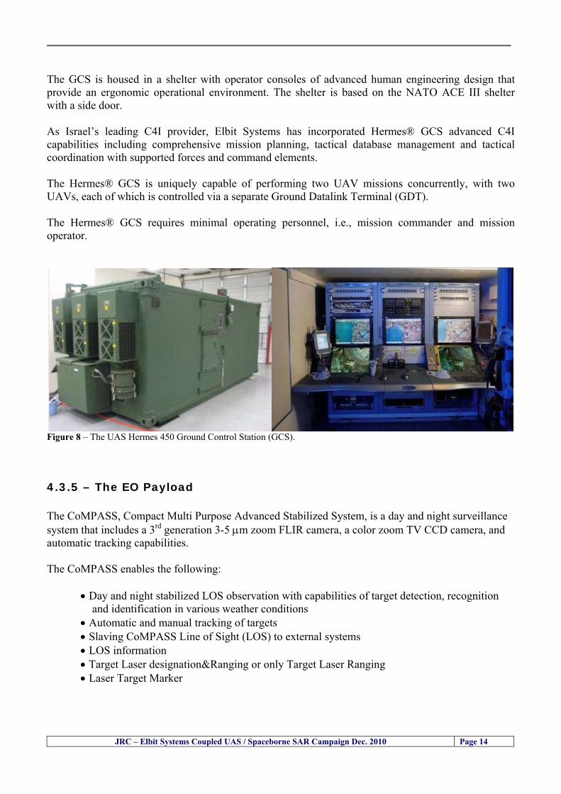
__________________________________________________________________________________
JRC ndash Elbit Systems Coupled UAS Spaceborne SAR Campaign Dec 2010 Page 14
The GCS is housed in a shelter with operator consoles of advanced human engineering design that provide an ergonomic operational environment The shelter is based on the NATO ACE III shelter with a side door As Israelrsquos leading C4I provider Elbit Systems has incorporated Hermesreg GCS advanced C4I capabilities including comprehensive mission planning tactical database management and tactical coordination with supported forces and command elements The Hermesreg GCS is uniquely capable of performing two UAV missions concurrently with two UAVs each of which is controlled via a separate Ground Datalink Terminal (GDT) The Hermesreg GCS requires minimal operating personnel ie mission commander and mission operator
Figure 8 ndash The UAS Hermes 450 Ground Control Station (GCS)
435 ndash The EO Payload The CoMPASS Compact Multi Purpose Advanced Stabilized System is a day and night surveillance system that includes a 3rd generation 3-5 μm zoom FLIR camera a color zoom TV CCD camera and automatic tracking capabilities The CoMPASS enables the following
bull Day and night stabilized LOS observation with capabilities of target detection recognition and identification in various weather conditions
bull Automatic and manual tracking of targets bull Slaving CoMPASS Line of Sight (LOS) to external systems bull LOS information bull Target Laser designationampRanging or only Target Laser Ranging bull Laser Target Marker
__________________________________________________________________________________
JRC ndash Elbit Systems Coupled UAS Spaceborne SAR Campaign Dec 2010 Page 15
CoMPASS the EOIR system for UAV applications is the most advanced payload version of the CoMPASS family featuring reduced weight high degree of modularity and flexibility space-saving packaging and advanced operational and video processing features The CoMPASS based STA Stabilized Turret Assembly is a single LRU housing
bull 3rd generation 3-5 μm FLIR zoom Camera bull Color Zoom TV CCD Camera bull Laser Target Designator bull Laser Target Marker bull Electronic Boards
Figure 9 ndash CoMPASS Stabilized Turret Assembly (STA)
__________________________________________________________________________________
JRC ndash Elbit Systems Coupled UAS Spaceborne SAR Campaign Dec 2010 Page 16
5 ndash Preliminary Data Analysis
51 ndash SAR Satellite Imagery Processing The high resolution spaceborne SAR image was analysed visually because the resolution is good enough to allow visual analysis and the site is too close to the coast which makes automatic processing more difficult and prone to error due to artefacts caused by land targets The Hermes 450 images were also analysed visually
52 ndash Ground Truth Data This section briefly describes the Ground Truth data namely the GPS positions of the boat deployed as target during the experiment a photo of the boat as well as other relevant ground truth data collected
521 ndash GPS coordinates of the boat deployed Table 5 gives the GPS coordinates of the boat deployed during the experiment at the time of the Radarsat-2 satellite overpass Table 3 ndash Ground Truth data collected at the time of the satellite pass (154740 UTC=174740 LT) on 8 December 2010
Date 8 Dec2010 Time 154740 UTC=174740 LT Pass Ascending
SatelliteMode Radarsat-2 Spotlight Polarisation HH
Boats Type Size Latitude Longitude
Elbits 12-meter
Boat
32˚ 51830 N 32deg514980N 32863833deg N
34˚ 57961 E 34deg575766E 34966017deg E
__________________________________________________________________________________
JRC ndash Elbit Systems Coupled UAS Spaceborne SAR Campaign Dec 2010 Page 17
521 ndash HERMES 450 Ground Truth Data Table 4 shows the 12-meter Elbitacutes Boat as detected by the IR sensor of the Hermes 450 Table 4 ndash Hermes 450 Ground Truth Data Date 8 Dec2010 Time 154740 UTC=174740 LT
Platform Hermes 450
UAV Type Size Latitude Longitude
UAV Hermes
450
174730h 3284489947 N
174800h
3285089687 N
174730h 3498564048 E
174800h
3499338667 E
Elbits 12-meter
Boat UAV
Image
32˚ 51830 N 32deg514980N 32863833deg N
34˚ 57961 E 34deg575766E 34966017deg E
53 ndash Weather Conditions and Sea State The weather conditions in Haifa are summarized in Table 5 bellow
Table 5 ndash Wind speed wind direction and Temperature Time (IST) Temp Dew
Point Humidity Pressure Visibility Wind Dir
Wind Speed
Gust Speed Precip Events Conditions
550 PM 210 degC 130 degC 60 1017 hPa - North 111 kmh
31 ms - NA Clear
__________________________________________________________________________________
JRC ndash Elbit Systems Coupled UAS Spaceborne SAR Campaign Dec 2010 Page 18
Figure 10 gives the weather data (Temperature Barometric Pressure Wind Speed and Wind Direction) for Haifa Israel on 8 Dec 2010
Figure 10 ndash Weather data (Temperature Barometric Pressure Wind Speed and Wind Direction) for Haifa Israel on 8 Dec 2010
__________________________________________________________________________________
JRC ndash Elbit Systems Coupled UAS Spaceborne SAR Campaign Dec 2010 Page 19
54 ndash Verification of the Results This section briefly describes the verification of the targets detected in the spaceborne SAR image and in the Hermes 450 UAV using the ground truth data collected during the experiment
541 ndash Overview of the UAV Trajectory and the SAR Imagery Footprint Figure 11 gives an overview of the UAV trajectory the footprint of the SAR imagery and the area of the experiment near the port of Haifa The UAV trajectory is depicted in blue The large red rectangle is the footprint of the TerraSAR-X Stripmap The smaller red rectangle is the footprint of the Radarsat-2 Spotlight image
Figure 11 ndash Google Earth UAV trajectory during the experiment and footprinst of the SAR imagery ordered for the experiment Figure 12 is a zoom in of the previous image which allows a more detailed view of the UAV trajectory and of the port of Haifa Figure 13 is a zoom in of figure 12 It shows in more detail the UAV trajectory during the entire experiment and the port of Haifa in Israel
__________________________________________________________________________________
Figure 12 ndash Zoom in of the previous figure showing a more detailed view of the UAV trajectory and of the port of Haifa in Israel
Figure 13 ndash Zoom in of the previous figure showing a even more detailed view of the UAV trajectory and of the port of Haifa in Israel
JRC ndash Elbit Systems Coupled UAS Spaceborne SAR Campaign Dec 2010 Page 20
__________________________________________________________________________________
JRC ndash Elbit Systems Coupled UAS Spaceborne SAR Campaign Dec 2010 Page 21
542 ndash Targets Detected in the Radarsat-2 Spotlight Image Figure 14 illustrates the position of the Elbitrsquos boat used as target in the experiment at the approximate time of the SAR Satellite pass by 1547 UTC (1747 LT) The small photo of the boat shows the approximate position of the boat The two small planes show the positions of the UAV immediately before and after the SAR Satellite pass
Figure 14 ndash Google Earth positions of the elbitrsquos boat and the UAV (Hermes450) at the approximate time of the SAR Satellite overpass by 174740 UTC Figure 15 shows the corresponding SAR image (Radarsat-2 Spotlight) acquired during the experiment Pins 1 and 2 represent the positions of the UAV before and after the SAR satellite overpass Pin 3 illustrates the position of the Elbitacutes boat deployed at the time of the satellite overpass At this scale the SAR signature of the boat is not distinguishable from the sea clutter background However zooming in the SAR image the SAR signature can clearly be seen as illustrated in figure 12 The SAR image in figure 12 also shows several SAR signatures of large ships in the area at the time of the satellite overpass
__________________________________________________________________________________
JRC ndash Elbit Systems Coupled UAS Spaceborne SAR Campaign Dec 2010 Page 22
Elbit`s Boat
Figure 15 ndash On the background the SAR image with the two UAV positions before and after the satellite overpass (Pin1 and Pin2) and the Elbitacutes Boat position (Pin3) The small window over the SAR image shows a zoom in of the SAR image where the SAR signature of the Elbitacutes Boat can clearly be seen The top right are of the SAR image also shows SAR signatures of several large ships in the area at the time of the SAR satellite overpass Figure 16 shows the corresponding SAR image (Radarsat-2 Spotlight) acquired during the experiment and the UAV IR images of some of the targets Pins 1 and 2 represent the positions of the UAV before and after the SAR satellite overpass Pin 3 illustrates the position of the Elbitacutes boat deployed at the time of the satellite overpass At this scale the SAR signature of the boat is not distinguishable from the sea clutter background However zooming in the SAR image the SAR signature can clearly be seen as illustrated in figure 13 On the top left the UAV IR image of the Elbitrsquos Boat The SAR image in figure 13 also shows several SAR signatures of large ships in the area at the time of the satellite overpass On the centre left the UAV IR image of a large ship On the centre right the UAV IR image of a large ship On the bottom right the UAV IR image of a large ship All the UAV images were acquired at night in complete darkness from altitudes in the order of 5500 meters Nonetheless the quality and detail of the UAV images allows classification of the targets and in some cases the identification As it can be seen the potential of UAV for maritime surveillance is very promising During the experiment the UAV detected all the boats and ships in the area and tracked some of the boatsships to test the tracking capability The capability of detection and tracking targets is a critical capability for maritime surveillance
__________________________________________________________________________________
JRC ndash Elbit Systems Coupled UAS Spaceborne SAR Campaign Dec 2010 Page 23
Elbitacutes Boat
Elbit`s Boat
Figure 16 ndash Zoom-in of figure 15 with the UAV images of some targets On the top left the UAV IR image of the Elbitrsquos Boat On the centre left the UAV IR image of a large ship On the centre right the UAV IR image of a large ship On the bottom right the UAV IR image of a large ship Figure 17 shows a comparison of the SAR and UAV images with an optical photo taken in Haifa Israel a couple of hours before the SAR satellites overpass Most of the large ships were detected in the SAR image and some of these ships can be identified in the optical photo Some of the ships in the photo left the area before the SAR satellites overpass
__________________________________________________________________________________
JRC ndash Elbit Systems Coupled UAS Spaceborne SAR Campaign Dec 2010 Page 24
Figure 17 ndash Photo taken in Haifa Israel a couple of hours before the SAR satellites overpass This phot shows the large ships moored in the area Most of these large ships were detected in the Radarsat-2 image As expected their positions and orientations were slightly different at the time of the satellite overpass
Elbitacutes Boat
Elbit`s Boat
__________________________________________________________________________________
JRC ndash Elbit Systems Coupled UAS Spaceborne SAR Campaign Dec 2010 Page 25
Figure 18 ndash Photo taken in Haifa Israel a couple of hours before the SAR satellites overpass This phot shows the large ships moored in the area Most of these large ships were detected in the Radarsat-2 image As expected their positions and orientations were slightly different at the time of the satellite overpass Figure 18 illustrates the SAR image and the corresponding google earth image of a small pier in the port of Haifa In the SAR image due to several artefacts it is not possible to detect the 7 small boats moored to the small pier The UAR IR image of the same area clearly shows the 7 small boats with impressive detail taking into account that the image was acquired from an altitude of about 5500 meters A zoom in of the same UAV IR image is shown in figure 19 As it can be seen although the image was acquired from an altitude of about 5500 meters the 7 small boats can be clearly seen with enough detail to allow classification of the type of boat A UAV flight at lower altitude would probably giver a lot more detail and eventually allow the identification of the small boats
__________________________________________________________________________________
JRC ndash Elbit Systems Coupled UAS Spaceborne SAR Campaign Dec 2010 Page 26
Figure 19 ndash UAV IR image of a small pier in the port of Haifa Israel where 7 small boats can be seen with enough detail to allow classification This image was acquired from an altitude of about 5500 meters in the dark
__________________________________________________________________________________
55 ndash Quantitative Analysis of the Spaceborne SAR Image In order to allow a quantitative analysis of the data the spaceborne SAR image was calibrated using ESArsquos NEST software package version 4B The input was the SAR image acquired and the output was the Radiometric Calibration (Sigma Naught (σdeg)) expressed in terms of intensity and in decibel (dB) the Radar Brightness (βdeg) and the Radiometric Normalisation (gamma naught (γdeg))
551 ndash Radarsat-2-Spotlight 08Dec2010 (154740 UTC) Haifa Israel Figure 20 illustrates the Intensity band of a subset of the Radarsat-2Spotlgiht image (08Dec2010)
Figure 20 ndash Radarsat-2 Spotlgiht image (08Dec2010) ndash Sigma Naught (Intensity) band
JRC ndash Elbit Systems Coupled UAS Spaceborne SAR Campaign Dec 2010 Page 27
__________________________________________________________________________________
Figure 21 illustrates the Sigma Naught Coefficient of the Radarsat-2 Spotlgiht image (08Dec2010) expressed in terms of intensity and decibel (dB)
Figure 21 ndash Radarsat-2 Spotlgiht image (08Dec2010) - On the left the Sigma Naught (σdeg) (intensity) and on the right the Sigma Naught (σdeg) (dB)
ormalisation amma Naught (γdeg)) of the Radarsat-2 Spotlgiht image (08Dec2010) expressed in dB
-2 Spotlgiht image (08Dec2010) - On the left the Beta Naught (βdeg) and on the right the Gamma Naught (γdeg) (dB)
Figure 22 illustrates the Radar Brightness (Beta Naught (βdeg)) and the radiometric n(G
Figure 22 ndash Radarsat
JRC ndash Elbit Systems Coupled UAS Spaceborne SAR Campaign Dec 2010 Page 28
__________________________________________________________________________________ Figure 23 shows the Sigma Naught (σdeg) in dB after some colour manipulation and the histogram of the Sigma Naught (σdeg) image
Figure 23 ndash Radarsat-2 Spotlgiht image (08Dec2010) - On the top left the Sigma Naught (σdeg) after colour manipulation to enhance the targets and on the top right the corresponding histogram On the bottom we can see the histogram of the image
Table 6 gives the statistics of the Sigma Naught (σdeg) Radarsat-2 Spotlgiht image (08Dec2010) The Sigma Naught (σdeg) range from -72897 dB up to 23465 dB The Mean value is -16855 dB the Median is -16594 dB and the standard deviation is 7077 dB
JRC ndash Elbit Systems Coupled UAS Spaceborne SAR Campaign Dec 2010 Page 29
__________________________________________________________________________________
JRC ndash Elbit Systems Coupled UAS Spaceborne SAR Campaign Dec 2010 Page 30
Table 6 ndash Statistics of the Radarsat-2 Spotlgiht image (08Dec2010) (154740 UTC)
Statistics Values Unit Only ROI-Mask pixels considered Number of pixels total Number of considered pixels Ratio of considered pixels
No 322394283 322394283
1000
Minimum Maximum
-728974609375 234655818939209
intensity_db intensity_db
Mean Median Std-Dev Coefficient of Variation
-16855686580177853 -1659462338617847 707796800831575
07888765273432338
intensity_db intensity_db intensity_db intensity_db
Checking the radar backscattering coefficient of some targets (small boat and some large ships) detected in the Radarsat-2 Spotlight image we get values ranging from -0379 dB up to 23455 dB The analysis of the Sigma Naught values (σdeg) of the targets and the area around the targets shows a significant contrast
56 ndash Summary of the Preliminary Analysis of the Spaceborne SAR Image This experiment involved two spaceborne SAR images namely a TerraSAR-X Stripmap and one Radarsat-2 Spotlight The TerraSAR-X image was not delivered by DLR due to technical problems The Elbitrsquos boat deployed during the experiment was detected in the Radarsat-2 Spotlight image Several other targets including a set of large ships were also detected Table 7 summarises the characteristics of the SAR image acquired and the targets detected
Table 7 ndash List of SAR Satellite Images acquired during the experiment and detected boats ISRAEL (HAIFA)
Date Time Place Satellite Mode Ground Truth Data Detected Boats
08Dec2010 (PM) Haifa - Israel Radarsat-2 Spotlight GPSPhotosMovies 1 small boat deployed + 9 large ships
Table 8 gives the minimum and maximum Sigma Naught (σdeg) of the targets detected in each SAR image
Table 8 ndash Minimum and maximum Sigma Naught (σdeg) of the targets detected in each SAR image
Date Time UTC (LT)Pass Satellite Image Mode Polarisation Sigma Naught (σdeg) Min Max
29Oct2010528UTC(728AM LT) DES Radarsat-2 Spotlight HH --0379 dB 23455 dB The SAR signatures of the boats deployed were very weak Some possible reasons to explain such weak signatures are the sea state the wind speed the incidence angle and the type and materials Another possible reason is the processing at DLR
__________________________________________________________________________________
JRC ndash Elbit Systems Coupled UAS Spaceborne SAR Campaign Dec 2010 Page 31
6 ndash Preliminary Conclusions The analysis of the results of this coupled UASSpaceborne SAR experiment shows a promising potential for the use of UAS for maritime surveillance UAS can be integrated into the airborne building block of maritime surveillance systems to complement the existing assets increase system performance and improve the overall maritime domain awareness The main perceived maritime security and safety threats comprise piracy terrorist and military threats weapons proliferationsmuggling drugs trafficking illegal immigration unlawful use of containers attacks to critical infrastructures and illegal fishing The main maritime security and safety gaps include a lack of technologies with the capability of detecting small targets (eg small boats) a lack of wide area and persistent maritime surveillance a lack of coordination and information sharing limited interoperability a lack of containers security a lack of persistent surveillance of critical infrastructures and early warning systems Unmanned Aircraft Systems (UAS) are an emerging technology with strong potential to mitigate the above mentioned threats by filing in the main maritime security and safety gaps listed earlier For instance the wide range of potential applications of UAS to maritime surveillance includes but is not limited to
bull detection classification and identification of small boats bull persistent maritime surveillance bull use as communications relays bull persistent surveillance of critical infrastructures bull early warning systems bull COMINT and ELINT collection etc
Table 11 illustrates the mapping of maritime securitysafety threats vs gaps and summarises the main potential applications of UAS to maritime surveillance The above mentioned potential applications of UAS to the Maritime Domain will be addressed in turn in more detail next bull Detection classification and identification of small boats ndash The capability of detecting classifying and identifying small targets (eg small boats) is among the key technologies required to improve maritime domain awareness This capability is critical to mitigate piracy illegal immigration drugs trafficking weapons smuggling illegal fishing terrorism and critical infrastructure Unmanned Aircraft Systems (UAS) provide this capability more efficiently and at a lower cost than any other existing technology bull Persistent maritime surveillance ndash With the continuous improvements of UAS technologies such as platforms sensors collision avoidance systems command and control systems telecommunications etc UAS are increasing their autonomy endurance and flexibility These characteristics are very important for persistent maritime surveillance UAS can be launched from land ships aircraft and technologies to launch UAS from submarines are currently under development UAS have distinct advantages over other existing technologies for persistent maritime surveillance in terms of autonomyendurance (the Global Surveyor has an autonomy of 1 week) cost (eg as the autonomy of UAS increases the number of staff required to operate UAS decreases) risk (eg if the UAS crashes the crew is not at risk) flexibility (eg they can be launched from a ship reducing the time to reach potential threats) etc
__________________________________________________________________________________
JRC ndash Elbit Systems Coupled UAS Spaceborne SAR Campaign Dec 2010 Page 32
bull Communications relays ndash UAS are being used as communication relays mainly in military context but have the potential to play a similar role in Civil context in several situations such as to replace satellite communications or as a redundant system over any location on Earth The main advantages of using UAS as communication relays is that airborne communication relays mitigate kinetic and noise jamming threats to satellite communications uplinks by providing an alternative set of links either directly to surface-based terminals or to satellites beyond the range of threats They are less susceptible to noise jamming threats than satellites because an adversary has to detect geolocate and track the airborne asset and operate within line of sight of the receive antenna main beam bull Persistent surveillance of critical infrastructures ndash The security of critical infrastructures such as nuclear power plants refineries ports etc requires persistent surveillance UAS can play an important role in providing persistent surveillance over critical infrastructures and over a wide area around the critical infrastructure Some advantages of UAS over other existing technologies such as ground-based assets (eg video cameras alarm systems manned aircraft etc) comprise the security of the UAS (eg hardly can be damaged or switched off as any ground-based asset) the area covered by a UAS (eg it is larger than the area covered by any ground-based asset) the cost (eg UAS is cheaper than manned aircraft with similar capability) etc bull Early warning systems ndash UAS have the potential to be used as part of an integrated system of systems for early warning A UAS can provide information about a given area at a fraction of the cost of alternative means Formation flying of UAS can cover a wide maritime area It is reasonable to assume that in a foreseeable future with the advent of UAS with increased autonomy the operations cost of UAS will likely decrease making them increasingly more attractive bull COMINT and ELINT collection ndash SIGNal INTelligence (SIGNINT) can be divided into two categories namely COMINT and ELINT COMINT stands for Communication Intelligence and ELINT for Electronic Intelligence Collection of COMINT is passive Exploitation of COMINT requires a human operator which implies COMINT UAS are suitable for COMINT and ELINT collection in different scenarios The relatively reduced amount of data collected and analysed during this experiment and the lessons learned do not allow drawing final conclusions about the feasibility of using Unmanned Aerial Systems (UAS) for maritime surveillance However this experiment allowed hands-on experience with UAS technologies and significantly improved the awareness for its applications to maritime surveillance and related issues involved including its potential the feasibility as well as the limiting and enabling factors These different aspects will now be analysed in turn in the next sections Table 11 illustrates the mapping of the main maritime security threats and gaps as well as the main priorities in terms of the different technologies involved in maritime surveillance For each maritime threat the technologies required to fill in each gap is indicated and its priority is expressed in a range of numbers (1 to 3 1 = Maximum Priority 2 = Medium Priority 3 = Low Priority) and colours (Red = Maximum Priority Orange = Medium Priority Green = Low Priority) The main technologies involved in maritime surveillance are listed on the bottom of figure 4 and are reproduced here for convenience of the reader 1- Reporting Systems 2- Sensors 3- Platforms 4- Communications 5- Data Fusion amp Sharing 6- Intelligence and 7- Databases For example the mitigation of the main threat Piracy requires filling in several maritime security gaps (eg lack of persistent surveillance lack of wide-are maritime surveillance lack of small boat detection lack of Early Warning Systems and lack of Information Sharing with maximum priority (1- Red) and among the required technologies listed are UAS LTAAV GEO-HR etc Concerning the remaining two gaps (Limited Interoperability and Containers Security) they are less relevant to mitigate Piracy hence the priority for Limited Interoperability is 2-Orange and for Containers Security is 3- Green
__________________________________________________________________________________ Table 9 ndash The Main Maritime Security and Safety Threats vs Gaps and the technologies that can be used to mitigate them
Maritime Security Main Threats GapsGapsrarr
darrThreats
Lack o f Risk As sessmentCapab ility
La ck of Persiste nt
Surveilla nce
La ck of Wid e-Area su rve illanc e
La ck of Small Boat De tecti on
Lack o f Earl y Warn ing Sys tems
L ack of In forma tion
Sh arin g
L imi ted In terop era bility
Lac k of Co ntai ners
Se cur ity
bull PiracyUAS LTAVG EO-
HR + UAS LT AVGEO-
HR + SAR GEO-HR
+ UAS USV LTAV
+ UAS LTAV
+ Coord in ationamp Sharing +
Inter opera bilityOptimisation +
1 2 3 5 6 7 1 2 3 5 6 7 1 2 3 5 6 1 2 3 123456 4567 1234567 1234567
bull Terro rismUAS LTAVG EO-
HR + UAS L TAV GEO-HR +
SAR AISGEO-HR +
UAS USV LTAV+
Intelligence+
Inte lligen ce+
Inter opera bilityOptimisation +
Intelligence+
1 2 3 5 6 7 1 2 3 5 6 1 2 3 5 6 1 2 3 123456 4567 1234567 1234567
bull Wea pon s ofM ass Dest ru ctio n Smugg ling
UAS LTAVG EO-HR +
UAS LT AVGEO-HR +
SAR AIS+
UAS USV LTAV+
Intelligence+
Inte lligen ce+
Intelligence+
Intelligence+
1 2 3 5 6 7 1 2 3 5 6 1 2 3 5 6 1 2 3 123456 4567 1234567 1234567
bull Drug sTraffic king
UAS LTAVG EO-HR +
UAS LT AVGEO-HR +
SAR AIS+
UAS USV LTAV+
Intelligence+
Inte lligen ce+
Intelligence+
Intelligence+
1 2 3 5 6 7 1 2 3 5 6 1 2 3 5 6 1 2 3 123456 4567 1234567 1234567
bull Illega lImmigratio n
UAS LTAVG EO-HR +
UAS LT AVGEO-HR +
SAR AIS+
UAS USV LTAV+
Intelligence+
Inte lligen ce+
Intelligence+
Intelligence+
1 2 3 5 6 7 1 2 3 5 6 1 2 3 5 6 1 2 3 123456 4567 1234567 1234567
bull Critic alI nfrastruc tureSecu rit y
UAS LTAVG EO-HR +
UAS LT AVGEO-HR +
SAR AIS+
UAS USV LTAV+ + Inte lligen ce
+ Intelligence
+ Intelligence
+
1 2 3 5 6 7 1 2 3 6 1 2 3 5 6 1 2 3 123456 4567 1234567 1234567
bull Illega lFish ing
UAS LTAVG EO-HR +
AI S+SAR UASLTAV +
SAR AIS GEO-HR+
UAS USV LTAV+
Intelligence+
Inte lligen ce+
Intelligence+
1 2 3 5 6 7 1 2 3 5 7 1 2 3 5 6 1 2 3 123456 4567 1234567
bull Un lawf ul Use of Co nta iners
(Secur ity)
UAS LTAVG EO-HR +
GPS Tr acking+
Intelligence+
Inte lligen ce+
GPS Int rusion Det ection Se al
1 2 3 5 6 7 4 6 7 1 2 3 5 6 1 2 3 123456 4567 1234567 1234567
(-) Priority (+) Not Rel evant
SURVEILLANCETECHNOLOGIES
1- Reporti ng Systems
2 -Sensors 3 -P latforms 4 - Communications 5- Data Fusionamp Sharing
6 -I ntelli gence 7 -Databases
JRC ndash Elbit Systems Coupled UAS Spaceborne SAR Campaign Dec 2010 Page 33
__________________________________________________________________________________
JRC ndash Elbit Systems Coupled UAS Spaceborne SAR Campaign Dec 2010 Page 34
61 ndash Hands-on experience with UAS technologies and its applications to maritime surveillance This coupled UASSpaceborne SAR campaign was a unique opportunity to acquire further handsndashon experience with UAS technologies and learn about the main issues related to its applications to maritime surveillance From the planning phase up to the execution of the UAS flight and landing there are several factors that need to be carefully analysed and taken into account A summary of the main issues identified in this experiment is given next 1- Selection of the Experiment Area Authorisation to Fly ndash For the time being UAS can only be flown in restricted areas usually under control of national authorities often the military This is due to the risks that a UAS can pose to human life and property In the present case an area under the authority of the Israeli Civil Aviation Authority was selected The authorisation to fly was not easy to obtain because the selected area is under the authority of the Civil Aviation Authority Figure 24 indicates the area of the experiment in Haifa Israel 2- UAS Communications Issues ndash The Hermes 450 was flown in Line-of-Sight (LOS) since it was close to the coast For BLOS (Beyond Line-of-Sight) operation satellite communications are required 3- Synthetic Aperture Radar (SAR) ndash The specific model Hermes 450W used in the experiment had no SAR sensor installed However a SAR sensor can be installed A SAR sensor is important for maritime surveillance since it allows 247 operations regardless of the weather conditions 4- Automatic Identification System (AIS) Receiver ndash The Hermes 450 used in this experiment was not equipped with an AIS receiver For maritime surveillance operations an AIS receiver is a very important tool since it allows the automatic identification of most ships allowing the UAS to concentrate on non-identified ships
__________________________________________________________________________________
Figure 24 ndash The area of the experiment is indicated by the GPS Trajectory of the UAV
62 ndash Potential of UAS for Maritime Surveillance UAS technologies are relatively recent and involve a wide range of fields spanning from aeronautics and sensors technologies to satellite communications and other engineering disciplines Innovations in each of the fields involved are emerging by the day UAS still have a long way to go before they become mature and their use fully operational For the time being UAS are mainly used for military applications However a large number of non-military UAS applications have been identified by stakeholders and there are several studies and demonstration flights foreseen for the near future Maritime surveillance is one of the most challenging and promising fields of application of UAS The challenges are due to the very demanding conditions under which the UAS must operate over sea and the requirements for safe operation
JRC ndash Elbit Systems Coupled UAS Spaceborne SAR Campaign Dec 2010 Page 35
__________________________________________________________________________________
JRC ndash Elbit Systems Coupled UAS Spaceborne SAR Campaign Dec 2010 Page 36
The present UAS experiment has unveiled some of the potential of UAS for maritime surveillance The UAS tests performed during this experiment include
1 ndash Detection of a Small rubber Boat and a Fishing Ship 2 ndash Tracking of a Small Boat and a Fishing Ship 3 ndash Classification of a Small Boat and a Fishing Ship 4 ndash Identification of a Small Boat and a Fishing Ship 5 ndash Detection and Tracking of People on the Beach
Despite the operational requirement that prevented the UAS from flying bellow 3km the experiment has confirmed the capability of UAS for small boat detection tracking and classification as well as the capability for people detection and tracking Concerning the identification of the targets the characteristics of the images acquired during this mission suggest that flying at lower altitudes the UAS images would allow the identification of the targets The UAS images can be seen from Figure 15 to 20
621 ndash Advantages of UAS for maritime Surveillance Some of the advantages of using UAS for maritime surveillance have been described in the literature and are summarized bellow
1- One potential benefit of UAS is that they could fill in a gap in current maritime surveillance by improving coverage
2- The range of UAS is a significant asset when compared to border agents on patrol or stationary surveillance equipment
3- Eletro-Optical InfraRed (EOIR) sensors (cameras) can identify small size objects from very high altitudes (high resolution)
4- UAS can provide precise and near-real-time imagery to a ground control operator who would then disseminate that information so that informed decisions regarding the deployment of border patrol agents can be made quickly
5- Long endurance UAS used along the border can fly for more than 30 hours up to several days without having to refuel compared with manned helicopterrsquos average flight time of just over 2 hours
6- The ability of UAS to loiter for prolonged periods of time has important operational advantages over manned aircraft
7- The longer flight times of UAS means that sustained coverage over a previously exposed area may improve maritime security
8- The range of UAVs is a significant asset when compared to border agents on patrol or stationary surveillance equipment Nevertheless the extended range and endurance of UAVs may lessen the burdens on human resources at the borders
9- UAS accidents do not risk the lives of pilots as do the helicopters and aircraft currently used by Coast Guards for border patrolling
__________________________________________________________________________________
JRC ndash Elbit Systems Coupled UAS Spaceborne SAR Campaign Dec 2010 Page 37
622 ndash Possible Drawbacks of using UAS for maritime Surveillance UAS also have disadvantages some of them are briefly described next
1- There have been concerns regarding the high accident rate of UAS which can be multiple times higher than that of manned aircraft Because UAS technology is still evolving there is less redundancy built into the operating system of UAS than of manned aircraft and until redundant systems are perfected mishap rates are expected to remain high
2- If control systems fail in a manned aircraft a well-trained pilot is better positioned to find the source of the problem because of hisher physical proximity If a UAS encountered a similar system failure or if a UAS landing was attempted during difficult weather conditions the ground control pilot would be at a disadvantage because he or she is removed from the event Unlike a manned pilot the remote pilot would not be able to assess important sensory information such as wind speed
3- Inclement weather conditions can also impinge on a UAS surveillance capability especially UAS equipped with only an EO camera and Forward Looking Infrared Radar (FLIR) because cloudy conditions and high humidity climates can distort the imagery produced by EO and FLIR equipment The effects of extreme climatic or atmospheric conditions on sensors reportedly can be mitigated with the outfit of one synthetic aperture radar (SAR) system and a moving target indicator (MTI) radar However adding SAR and MTI to a UAS platform would increase the costs associated with using UAS
4- Depending on the type of UAS the costs of operating a UAS can be higher than the costs of operating a manned aircraft This is because some types of UAS require a significant amount of logistical support and specialized operator and maintenance training Operating one UAS may require a crew of up to 20 support personnel The high comparative costs of operating some sophisticated types of UAS may be offset somewhat by their comparatively lower unit costs
63 ndash Main Limiting Factors Preventing the Use of UAS Several pre-requisites must be satisfied to render the UAS a viable cost-effective and regulated alternative to existing resources Major civil and commercial market barriers include
Single European Sky Sense and Avoid technologies Command and Control Technologies Reliability Communications (Bandwidth LOS BLOS)
Lack of airspace regulation that covers all types of UAV systems (encompassing lsquosense and avoidrsquo airspace integration and airworthiness issues)
Affordability - price and customization issues (eg commercial off-the-shelf open modular architecture) Lack of efforts to establish joint customer requirements (although this is gradually changing) Liability for civil operation Capacity for payload flexibility Lack of sufficient secure non-military frequencies for civil operation Perceived reliability (eg vehicle attrition rate vs manned aircraft) Operator training issues Recognitioncustomer perception of the UAV market Technology developments for multi-mission capability
__________________________________________________________________________________
64 ndash UAS Key Enabling Technologies Figure 25 illustrates the components of a typical UAV System showing some of the capabilities needed and the enabling technologies required for performing a given mission Any UAV mission involves many capabilities and technologies Due to the depicted system complexity the main key players such as the US Department of Defense (DoD) and other agencies have started to use the term Unmanned Aerial System (UAS) in place of UAV
Figure 25 ndash Unmanned Aerial Vehicle System Enabled by Autonomous Mission Management Reliable Flight Systems Navigation Accurate Systems Terrain Avoidance Power and Propulsion Some UAS key enabling technologies are listed below
Autonomous Mission Management Collision Avoidance Intelligent System Health Monitoring
Reliable Flight Systems Sophisticated Contingency Management Intelligent Data Handling and Processing Over-the-Horizon Communication Network-Centric Communication Open Architecture Power and Propulsion Navigation Accurate System Technology Enhanced Structures
JRC ndash Elbit Systems Coupled UAS Spaceborne SAR Campaign Dec 2010 Page 38
__________________________________________________________________________________
JRC ndash Elbit Systems Coupled UAS Spaceborne SAR Campaign Dec 2010 Page 39
Table 12 gives a more detailed description of other critical technologies for emerging autonomous UAV systems both civil and military Most of the technologies mentioned in Table 12 apply both to civil and military UAV systems Table 10 ndash Key Enabling Technologies (from SG75 study on autonomous systems)
Critical Technologies Decision Making Software
bull Fuzzy-based decision making bull Knowledge-based system bull Case-based reasoning bull Self-learning techniques bull Decision tree evaluation bull ReasoningInferring bull Probabilisticstochastic reasoning
Prediction Algorithms bull Predictive pathintent algorithms bull Short reaction algorithm bull Effectiveness evaluation
Status Assessment Software bull Internal status analysis bull Self-orientation
Situation Analysis Software bull Situation analysis bull Environmental analysis bull External status analysis
Modelling Software bull Air vehicle modelling algorithms bull Sensor modelling algorithms bull Scenario generation bull Threat system modeling bull Attack simulation bull Mission success optimisation model bull Simulation
Sensor Processing Software bull Sensor fusion bull Area of interest identification bull Automatic target recognition
Adaptive and Self-learning Systems bull Failure self-compensation
Attack Planning Software bull Attack plans and tactical alternatives bull Plan change impact identification
Weapon Engagement Procedure Software bull Weapon engagement algorithms
Mission Plan Update Software bull Route planning system bull Payload plan management system bull Mission Success Optimisation model
Path Optimisation Software bull Optimal trajectory planning bull Path Optimisation System
Targeting Software bull Target tracking bull Target prioritisation
Platform Technologies bull Obstacle detection and avoidance (airborne) bull Obstacle detection and avoidance (ground) bull Improved autopilot bull Speech recognition
Figure 26 summarises system element designs needed to transition from current to next-generation autonomous UAV systems for civilian and military UAS
__________________________________________________________________________________
Figure 26 ndash System Element Designs Needed to Transition from Current to Next-Generation Autonomous UAV Systems These new paradigms are a combination of system attributes and technological capabilities For instance the data fusion secure anti-jam and coordinated multi-vehicle control require technological development as well as specific system development to bring full maturity to unmanned systems Finally very small Micro UAVs (MAVs) and relatively large sophisticated UCAV systems are examples of the range of UAVs that are applying the new platforms payloads onboard processing communications etc to create next generation automated UAVs It is with these new platforms payloads etc that both UCAVs and MAV will be able to address similar operational challenges including
Mixed operation with other assets bull Deconfliction collision avoidance C4I integration
Operation over populated areas bull Safety issues Need to reduce reliance on communications bull UCAV ndash countermeasures bull MAV ndash limited size and power bull Limited line of sight environment Need a fully integrated system bull MAV propulsionpower generation still critical bull Operator machine interface critical bull All weather operations bull Survivability
JRC ndash Elbit Systems Coupled UAS Spaceborne SAR Campaign Dec 2010 Page 40
__________________________________________________________________________________
JRC ndash Elbit Systems Coupled UAS Spaceborne SAR Campaign Dec 2010 Page 41
65 ndash Mission Readiness
651 ndash Mission Readiness Summary This section summarises civil UAV mission readiness The purpose of Mission Readiness is to assess the readiness status of the different technologies involved in UAS In the present case this civil UAV mission readiness based on technology maturation forecasts that meet or exceed the desired or required capabilities identified by the user community Figure 27 summarises the mission readiness time forecasts for the different technologies The technologies annotated with an asterisk () are shown within the figure with maturation forecasts based on development targets expressed in the US Department of Defencesrsquo UAV Roadmap document The purpose of the chart is to be able to identify when the capability to fly a particular mission can be expected as a function of time The left-most end is the least probable and the right end the most probable timeframe
Figure 27 ndash Technology Maturation Summaries in Terms of Mission-Derived Capabilities
__________________________________________________________________________________
JRC ndash Elbit Systems Coupled UAS Spaceborne SAR Campaign Dec 2010 Page 42
66 ndash Small Boat Detection in SAR Satellite Imagery The use of spaceborne SAR imagery for small boat detection requires additional small boat detection experiments under different conditions using different methods It is not possible to draw final conclusions based on a limited number of small boat detection experiments which are not representative of the multiple possible scenarios
67 ndash Limitations of current State-of-the-Art SAR Satellite technology The main limitations of current State-of-the-Art spaceborne SAR imagery for maritime surveillance in particular aimed at small boat detection are 1 - SAR satellites repeat cycles do not allow the coverage of the same area at the required time intervals Constellations of SAR satellites could be a solution 2 - The conflict between resolution and image swath High resolution is required to detect small boats However the high resolution images have small swaths Maritime surveillance with high resolution images would require a large number of images to cover wide maritime areas which is very expensive and for the time being technically not feasible Intelligence data can play an important role by indicating an approximate position of suspicious non cooperative targets therefore reducing the surveillance area which can then be imaged using high resolution images 3- Spaceborne high resolution SAR imagery acquisition times are long enough to allow significant motion of the target during the acquisition time degrading the quality of the image Further research efforts are needed to develop new sensors and platforms As far as sensors are concerned shorter integration times are needed to prevent the blurring effect caused by the motion of the targets Regarding the platforms more platforms are needed to allow lower repeat cycles and improved coverage
__________________________________________________________________________________
JRC ndash Elbit Systems Coupled UAS Spaceborne SAR Campaign Dec 2010 Page 43
7 ndash Plans for Future Work The controlled experiments carried out by the EC-JRC together with Elbit Systems in Haifa-Israel comprised the deployment of a UAS (Hermes-450) and one small 12-meter boat A Radarsat-2 Spotlight image was acquired and several images collected by the Hermes-450 The experiment unveiled the potential of UAS for maritime surveillance in particular for detection tracking classification and possible identification of small targets The UAS was able to detect track and classify small targets such as small boats For low UAS altitude flights identification may be possible in some cases The small 12-meter boat was detected in the spaceborne SAR image The small boat detection trials carried out by the JRC were very successful since most small boats deployed during the experiments were detected in different sea states wind speeds and geographical locations The several small boat detection campaigns conducted by the EC-JRC seem to suggest that the probability of detection of small boats in spaceborne SAR images strongly depends on factors such as the sea state the wind speed the type of boat (shape and materials) the weather conditions among other factors The results of the experiments conducted thus far are not enough to draw final conclusions about the feasibility of using spaceborne SAR imagery for small boat detection However the experiments have an overall positive outcome because they indicate that under suitable sea state and wind speed conditions it is possible to detect small boats using spaceborne SAR The estimation of the probability of detection of small boats in spaceborne SAR images requires a large number of experiments under different circumstances (eg sea state wind speed characteristics of the targets image type and mode etc) Future plans include additional UAS experiments to asses its potential for maritime surveillance
Acknowledgements ndash The authors would like to express their gratitude to Elbit Systems for their cooperation logistical support and assets deployed without which the present coupled UASSAR Satellite Small Boat Detection Campaign would have not been possible
__________________________________________________________________________________
JRC ndash Elbit Systems Coupled UAS Spaceborne SAR Campaign Dec 2010 Page 44
REFERENCES [1] Elbit Systems ldquoUAV Elbit Systems Proposal for Unmanned Aerial Vehicle (UAV) flight to
collect Ground Truth data during a Maritime Surveillance Campaign and demonstrate UAV capabilities for Maritime Surveillancerdquo 2010
[2] ndash Cheryl Yuhas Suborbital Science Program Manager NASA Science Mission Directorate ldquoEarth Observations and the Role of UAVs A Capabilities Assessment Version 11rdquo Civil UAV Assessment Team httpwwwnasagovcentersdrydenresearchcivuavindexhtml August 2006
[3] ndash Document NIAG (SG75) NATO Industrial Advisory Group Study Group 75 Pre-Feasibility Study on UAV Autonomous Operations 2004
[4] ndash United States Department of Defence (DoD) Directive 50001 ldquoThe Defense Acquisition Systemrdquo and DoD Instruction 50002 ldquoOperation of the Defense Acquisition Systemrdquo
[5] ndash Mr James Ramage Mr Massimo Avalle Dr Erik Berglund Dr Luigi Crovella Mr Robert Frampton Dr Uwe Krogmann Mr Christian Ravat Mr Mike Robinson Dr Axel Schulte Dr Scott Wood ldquoRTO-TR-SCI-118 - Automation Technologies and Application Considerations for Highly Integrated Mission Systemsrdquo RTO-TR-SCI-118 AC323(SCI-118)TP204 January 2009
[6] Victor MG Silva Gilles Jurquet Gabriel Marchalot Maria TG Calzado Txema Soroa Juan Sancho Adam Koubek Harm Greidanus and Claudio Savarino ldquoWide Maritime Area Airborne Surveillance (WIMA2S) WP5 Final Reportrdquo WIMAAS WP5 FP7 Project 2008-2011 - ISBN-978-92-79-22801-8 (print) 978-92-79-22802-5 (PDF) ISSN-1018-5593 (print) 1831-9424 (online) EC-JRC Scientific Report JRC 70093 2012
[7] Victor MG Silva and Harm Greidanus ldquoSpaceborne SAR Small Boat Detection Campaign in Portugal and Spainrdquo EUR 25281 EN ISBN 978-92-79-22553-6 ISSN 1831-9424 (online) EC-JRC Scientific Report JRC68160 2012
[8] Goncalves Da Silva V Van Wimersma Greidanus H Hejmanowska B Loudjani P ldquoUAS Applications With Societal Benefits ndash JRCrsquos UAS-Related Activitiesrdquo 2011-2012 UAS Yearbook - UAS Unmanned Aircraft Systems - The Global Perspective 9 (9) 2011 p 127-129 JRC66600
[9] Goncalves Da Silva V Van Wimersma Greidanus H ldquoSmall boat detection using TerraSAR-X and Radarsat2 satellite imageryrdquo 4th TerraSAR-X Science Team Meeting 14 February 2011 DLR Oberpfaffenhofen (Germany) German Aerospace Center (DLR) (Organiser) 2011 JRC63663
[10] V Silva Harm Greidanus ldquoJRC - SAR Satellite Small Boat Detection Campaign - Portoroz ndash Sloveniardquo - ISBN-13 978-92-79-21476-9 ISSN (online) 1831-9424 EC-JRC Scientific Report JRC66835 2011
[11] V Silva Harm Greidanus ldquoJRC - SAR satellite small boat detection campaign - Algarve Portugalrdquo - ISBN-13 978-92-79-21265-9 ISSN (online) 1831-9424 ISSN (print) 1018-5593 EC-JRC Scientific Report JRC66631 2011
[12] ndash Goncalves Da Silva V Van Wimersma Greidanus H ldquoJRC-Frontex Spaceborne SAR Small Boat Detection Campaign ndash Italy amp Spainrdquo - ISBN-13 978-92-79-22213-9 ISSN (online) 1831-9424 EC-JRC Scientific Report JRC67517 2011
[13] - PW Vachon SJ Thomas J Cranton HR Edel and MD Henschel Validation of ship detection by the RADARSAT synthetic aperture radar and the Ocean Monitoring Workstation Canadian Journal of Remote Sensing 26(3)200ndash212 2000
[14] - Crisp D (2004) The state-of-the-art in ship detection in Synthetic Aperture Radar imagery DSTO Information Sciences Laboratory Australia
[15] - Joint Research Centre (JRC) of the European Community mdash IMPAST and DECLIMS web site httpintelligencejrcceceuintmarinefishindexhtm
[16] - McCandless SW Jackson CR (2004) Principles of Synthetic Aperture Radar Synthetic Aperture Radar Marine Users Manual NOAA Washington pp 1-23
[17] - Greidanus H (2008) Satellite Imaging for Maritime Surveillance of the European Seas Remote Sensing of the European Seas 343-358
European Commission
EUR 25346 EN --- Joint Research Centre --- Institute for the Protection and Security of the Citizen
Title JRC --- Elbit Systems Coupled UAS and Spaceborne SAR Campaign in Israel
Authors Victor MG Silva Harm Greidanus
Luxembourg Publications Office of the European Union
2012 --- v+44 pp --- 210 x 297 cm
EUR --- Scientific and Technical Research series --- ISSN 181-9424 (online) ISSN 1018-5593 (print)
ISBN 978-92-79-25020-0
doi10278828527
Abstract The European maritime area is one of Europersquos most important assets with regard to resources security and ultimately
prosperity of the Member States A significant part of Europersquos economy relies directly or indirectly on it It is not just the
shipping or fisheries industries and their related activities It is also shipbuilding and ports marine equipment and offshore
energy maritime and coastal tourism aquaculture submarine telecommunications blue biotech and the protection of the
marine environment The European maritime area faces several risks and threats posed by unlawful activities such as drugs
trafficking smuggling illegal immigration organised crime and terrorism Piracy in international waters also constitutes a threat
to Europe since it can disrupt the maritime transport chain These risks and threats can endanger human lives marine resources
and the environment as well as significantly disrupt the transport chain and global and local security It is anticipated that these
risks and threats will endure in the mid and long run In order to keep Europe as a world leader in the global maritime economy
an effective integratedinteroperable sustainable maritime surveillance system and situational awareness are needed
A significant number of unlawful maritime activities such as illegal immigration drugs trafficking smuggling piracy and
terrorism involve mainly small boats because small boats are faster and more difficult to detect using conventional means
Hence it is very important to find out the feasibility of using Unmanned Aerial Systems (UAS) for small boat detection tracking
classification and identification as well as to study the potential of UAS for maritime surveillance Since 2010 the EC-JRC has
carried out a number of UAS maritime surveillance campaigns to study the potential of UAS for maritime surveillance in
particular for small boat detection This report presents the results and conclusions of the JRC --- Elbit Systems Coupled UAS and
Spaceborne SAR campaign carried out in Dec 2010 in Haifa Israel
As the Commissionrsquos in-house science service the Joint Research Centrersquos mission is to provide EU policies with independent evidence-based scientific and technical support throughout the whole policy cycle Working in close cooperation with policy Directorates-General the JRC addresses key societal challenges while stimulating innovation through developing new standards methods and tools and sharing and transferring its know-how to the Member States and international community Key policy areas include environment and climate change energy and transport agriculture and food security health and consumer protection information society and digital agenda safety and security including nuclear all supported through a cross-cutting and multi-disciplinary approach
LB-NA-25346-EN
-N
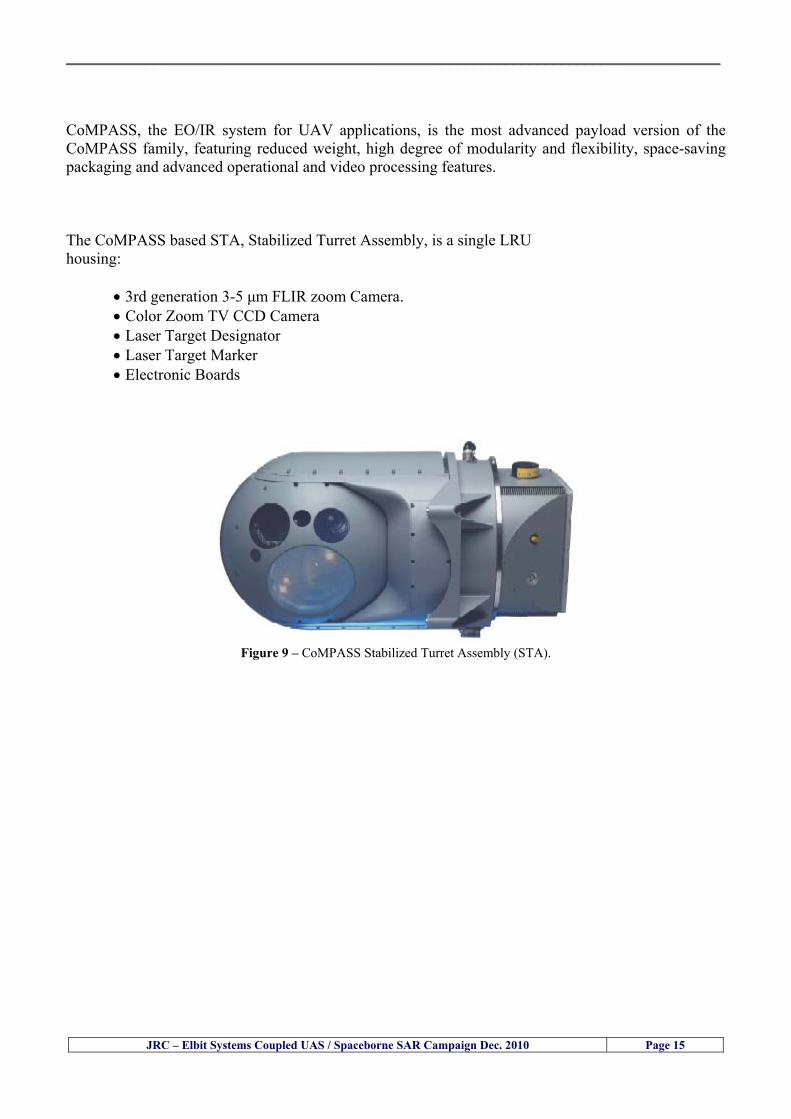
__________________________________________________________________________________
JRC ndash Elbit Systems Coupled UAS Spaceborne SAR Campaign Dec 2010 Page 15
CoMPASS the EOIR system for UAV applications is the most advanced payload version of the CoMPASS family featuring reduced weight high degree of modularity and flexibility space-saving packaging and advanced operational and video processing features The CoMPASS based STA Stabilized Turret Assembly is a single LRU housing
bull 3rd generation 3-5 μm FLIR zoom Camera bull Color Zoom TV CCD Camera bull Laser Target Designator bull Laser Target Marker bull Electronic Boards
Figure 9 ndash CoMPASS Stabilized Turret Assembly (STA)
__________________________________________________________________________________
JRC ndash Elbit Systems Coupled UAS Spaceborne SAR Campaign Dec 2010 Page 16
5 ndash Preliminary Data Analysis
51 ndash SAR Satellite Imagery Processing The high resolution spaceborne SAR image was analysed visually because the resolution is good enough to allow visual analysis and the site is too close to the coast which makes automatic processing more difficult and prone to error due to artefacts caused by land targets The Hermes 450 images were also analysed visually
52 ndash Ground Truth Data This section briefly describes the Ground Truth data namely the GPS positions of the boat deployed as target during the experiment a photo of the boat as well as other relevant ground truth data collected
521 ndash GPS coordinates of the boat deployed Table 5 gives the GPS coordinates of the boat deployed during the experiment at the time of the Radarsat-2 satellite overpass Table 3 ndash Ground Truth data collected at the time of the satellite pass (154740 UTC=174740 LT) on 8 December 2010
Date 8 Dec2010 Time 154740 UTC=174740 LT Pass Ascending
SatelliteMode Radarsat-2 Spotlight Polarisation HH
Boats Type Size Latitude Longitude
Elbits 12-meter
Boat
32˚ 51830 N 32deg514980N 32863833deg N
34˚ 57961 E 34deg575766E 34966017deg E
__________________________________________________________________________________
JRC ndash Elbit Systems Coupled UAS Spaceborne SAR Campaign Dec 2010 Page 17
521 ndash HERMES 450 Ground Truth Data Table 4 shows the 12-meter Elbitacutes Boat as detected by the IR sensor of the Hermes 450 Table 4 ndash Hermes 450 Ground Truth Data Date 8 Dec2010 Time 154740 UTC=174740 LT
Platform Hermes 450
UAV Type Size Latitude Longitude
UAV Hermes
450
174730h 3284489947 N
174800h
3285089687 N
174730h 3498564048 E
174800h
3499338667 E
Elbits 12-meter
Boat UAV
Image
32˚ 51830 N 32deg514980N 32863833deg N
34˚ 57961 E 34deg575766E 34966017deg E
53 ndash Weather Conditions and Sea State The weather conditions in Haifa are summarized in Table 5 bellow
Table 5 ndash Wind speed wind direction and Temperature Time (IST) Temp Dew
Point Humidity Pressure Visibility Wind Dir
Wind Speed
Gust Speed Precip Events Conditions
550 PM 210 degC 130 degC 60 1017 hPa - North 111 kmh
31 ms - NA Clear
__________________________________________________________________________________
JRC ndash Elbit Systems Coupled UAS Spaceborne SAR Campaign Dec 2010 Page 18
Figure 10 gives the weather data (Temperature Barometric Pressure Wind Speed and Wind Direction) for Haifa Israel on 8 Dec 2010
Figure 10 ndash Weather data (Temperature Barometric Pressure Wind Speed and Wind Direction) for Haifa Israel on 8 Dec 2010
__________________________________________________________________________________
JRC ndash Elbit Systems Coupled UAS Spaceborne SAR Campaign Dec 2010 Page 19
54 ndash Verification of the Results This section briefly describes the verification of the targets detected in the spaceborne SAR image and in the Hermes 450 UAV using the ground truth data collected during the experiment
541 ndash Overview of the UAV Trajectory and the SAR Imagery Footprint Figure 11 gives an overview of the UAV trajectory the footprint of the SAR imagery and the area of the experiment near the port of Haifa The UAV trajectory is depicted in blue The large red rectangle is the footprint of the TerraSAR-X Stripmap The smaller red rectangle is the footprint of the Radarsat-2 Spotlight image
Figure 11 ndash Google Earth UAV trajectory during the experiment and footprinst of the SAR imagery ordered for the experiment Figure 12 is a zoom in of the previous image which allows a more detailed view of the UAV trajectory and of the port of Haifa Figure 13 is a zoom in of figure 12 It shows in more detail the UAV trajectory during the entire experiment and the port of Haifa in Israel
__________________________________________________________________________________
Figure 12 ndash Zoom in of the previous figure showing a more detailed view of the UAV trajectory and of the port of Haifa in Israel
Figure 13 ndash Zoom in of the previous figure showing a even more detailed view of the UAV trajectory and of the port of Haifa in Israel
JRC ndash Elbit Systems Coupled UAS Spaceborne SAR Campaign Dec 2010 Page 20
__________________________________________________________________________________
JRC ndash Elbit Systems Coupled UAS Spaceborne SAR Campaign Dec 2010 Page 21
542 ndash Targets Detected in the Radarsat-2 Spotlight Image Figure 14 illustrates the position of the Elbitrsquos boat used as target in the experiment at the approximate time of the SAR Satellite pass by 1547 UTC (1747 LT) The small photo of the boat shows the approximate position of the boat The two small planes show the positions of the UAV immediately before and after the SAR Satellite pass
Figure 14 ndash Google Earth positions of the elbitrsquos boat and the UAV (Hermes450) at the approximate time of the SAR Satellite overpass by 174740 UTC Figure 15 shows the corresponding SAR image (Radarsat-2 Spotlight) acquired during the experiment Pins 1 and 2 represent the positions of the UAV before and after the SAR satellite overpass Pin 3 illustrates the position of the Elbitacutes boat deployed at the time of the satellite overpass At this scale the SAR signature of the boat is not distinguishable from the sea clutter background However zooming in the SAR image the SAR signature can clearly be seen as illustrated in figure 12 The SAR image in figure 12 also shows several SAR signatures of large ships in the area at the time of the satellite overpass
__________________________________________________________________________________
JRC ndash Elbit Systems Coupled UAS Spaceborne SAR Campaign Dec 2010 Page 22
Elbit`s Boat
Figure 15 ndash On the background the SAR image with the two UAV positions before and after the satellite overpass (Pin1 and Pin2) and the Elbitacutes Boat position (Pin3) The small window over the SAR image shows a zoom in of the SAR image where the SAR signature of the Elbitacutes Boat can clearly be seen The top right are of the SAR image also shows SAR signatures of several large ships in the area at the time of the SAR satellite overpass Figure 16 shows the corresponding SAR image (Radarsat-2 Spotlight) acquired during the experiment and the UAV IR images of some of the targets Pins 1 and 2 represent the positions of the UAV before and after the SAR satellite overpass Pin 3 illustrates the position of the Elbitacutes boat deployed at the time of the satellite overpass At this scale the SAR signature of the boat is not distinguishable from the sea clutter background However zooming in the SAR image the SAR signature can clearly be seen as illustrated in figure 13 On the top left the UAV IR image of the Elbitrsquos Boat The SAR image in figure 13 also shows several SAR signatures of large ships in the area at the time of the satellite overpass On the centre left the UAV IR image of a large ship On the centre right the UAV IR image of a large ship On the bottom right the UAV IR image of a large ship All the UAV images were acquired at night in complete darkness from altitudes in the order of 5500 meters Nonetheless the quality and detail of the UAV images allows classification of the targets and in some cases the identification As it can be seen the potential of UAV for maritime surveillance is very promising During the experiment the UAV detected all the boats and ships in the area and tracked some of the boatsships to test the tracking capability The capability of detection and tracking targets is a critical capability for maritime surveillance
__________________________________________________________________________________
JRC ndash Elbit Systems Coupled UAS Spaceborne SAR Campaign Dec 2010 Page 23
Elbitacutes Boat
Elbit`s Boat
Figure 16 ndash Zoom-in of figure 15 with the UAV images of some targets On the top left the UAV IR image of the Elbitrsquos Boat On the centre left the UAV IR image of a large ship On the centre right the UAV IR image of a large ship On the bottom right the UAV IR image of a large ship Figure 17 shows a comparison of the SAR and UAV images with an optical photo taken in Haifa Israel a couple of hours before the SAR satellites overpass Most of the large ships were detected in the SAR image and some of these ships can be identified in the optical photo Some of the ships in the photo left the area before the SAR satellites overpass
__________________________________________________________________________________
JRC ndash Elbit Systems Coupled UAS Spaceborne SAR Campaign Dec 2010 Page 24
Figure 17 ndash Photo taken in Haifa Israel a couple of hours before the SAR satellites overpass This phot shows the large ships moored in the area Most of these large ships were detected in the Radarsat-2 image As expected their positions and orientations were slightly different at the time of the satellite overpass
Elbitacutes Boat
Elbit`s Boat
__________________________________________________________________________________
JRC ndash Elbit Systems Coupled UAS Spaceborne SAR Campaign Dec 2010 Page 25
Figure 18 ndash Photo taken in Haifa Israel a couple of hours before the SAR satellites overpass This phot shows the large ships moored in the area Most of these large ships were detected in the Radarsat-2 image As expected their positions and orientations were slightly different at the time of the satellite overpass Figure 18 illustrates the SAR image and the corresponding google earth image of a small pier in the port of Haifa In the SAR image due to several artefacts it is not possible to detect the 7 small boats moored to the small pier The UAR IR image of the same area clearly shows the 7 small boats with impressive detail taking into account that the image was acquired from an altitude of about 5500 meters A zoom in of the same UAV IR image is shown in figure 19 As it can be seen although the image was acquired from an altitude of about 5500 meters the 7 small boats can be clearly seen with enough detail to allow classification of the type of boat A UAV flight at lower altitude would probably giver a lot more detail and eventually allow the identification of the small boats
__________________________________________________________________________________
JRC ndash Elbit Systems Coupled UAS Spaceborne SAR Campaign Dec 2010 Page 26
Figure 19 ndash UAV IR image of a small pier in the port of Haifa Israel where 7 small boats can be seen with enough detail to allow classification This image was acquired from an altitude of about 5500 meters in the dark
__________________________________________________________________________________
55 ndash Quantitative Analysis of the Spaceborne SAR Image In order to allow a quantitative analysis of the data the spaceborne SAR image was calibrated using ESArsquos NEST software package version 4B The input was the SAR image acquired and the output was the Radiometric Calibration (Sigma Naught (σdeg)) expressed in terms of intensity and in decibel (dB) the Radar Brightness (βdeg) and the Radiometric Normalisation (gamma naught (γdeg))
551 ndash Radarsat-2-Spotlight 08Dec2010 (154740 UTC) Haifa Israel Figure 20 illustrates the Intensity band of a subset of the Radarsat-2Spotlgiht image (08Dec2010)
Figure 20 ndash Radarsat-2 Spotlgiht image (08Dec2010) ndash Sigma Naught (Intensity) band
JRC ndash Elbit Systems Coupled UAS Spaceborne SAR Campaign Dec 2010 Page 27
__________________________________________________________________________________
Figure 21 illustrates the Sigma Naught Coefficient of the Radarsat-2 Spotlgiht image (08Dec2010) expressed in terms of intensity and decibel (dB)
Figure 21 ndash Radarsat-2 Spotlgiht image (08Dec2010) - On the left the Sigma Naught (σdeg) (intensity) and on the right the Sigma Naught (σdeg) (dB)
ormalisation amma Naught (γdeg)) of the Radarsat-2 Spotlgiht image (08Dec2010) expressed in dB
-2 Spotlgiht image (08Dec2010) - On the left the Beta Naught (βdeg) and on the right the Gamma Naught (γdeg) (dB)
Figure 22 illustrates the Radar Brightness (Beta Naught (βdeg)) and the radiometric n(G
Figure 22 ndash Radarsat
JRC ndash Elbit Systems Coupled UAS Spaceborne SAR Campaign Dec 2010 Page 28
__________________________________________________________________________________ Figure 23 shows the Sigma Naught (σdeg) in dB after some colour manipulation and the histogram of the Sigma Naught (σdeg) image
Figure 23 ndash Radarsat-2 Spotlgiht image (08Dec2010) - On the top left the Sigma Naught (σdeg) after colour manipulation to enhance the targets and on the top right the corresponding histogram On the bottom we can see the histogram of the image
Table 6 gives the statistics of the Sigma Naught (σdeg) Radarsat-2 Spotlgiht image (08Dec2010) The Sigma Naught (σdeg) range from -72897 dB up to 23465 dB The Mean value is -16855 dB the Median is -16594 dB and the standard deviation is 7077 dB
JRC ndash Elbit Systems Coupled UAS Spaceborne SAR Campaign Dec 2010 Page 29
__________________________________________________________________________________
JRC ndash Elbit Systems Coupled UAS Spaceborne SAR Campaign Dec 2010 Page 30
Table 6 ndash Statistics of the Radarsat-2 Spotlgiht image (08Dec2010) (154740 UTC)
Statistics Values Unit Only ROI-Mask pixels considered Number of pixels total Number of considered pixels Ratio of considered pixels
No 322394283 322394283
1000
Minimum Maximum
-728974609375 234655818939209
intensity_db intensity_db
Mean Median Std-Dev Coefficient of Variation
-16855686580177853 -1659462338617847 707796800831575
07888765273432338
intensity_db intensity_db intensity_db intensity_db
Checking the radar backscattering coefficient of some targets (small boat and some large ships) detected in the Radarsat-2 Spotlight image we get values ranging from -0379 dB up to 23455 dB The analysis of the Sigma Naught values (σdeg) of the targets and the area around the targets shows a significant contrast
56 ndash Summary of the Preliminary Analysis of the Spaceborne SAR Image This experiment involved two spaceborne SAR images namely a TerraSAR-X Stripmap and one Radarsat-2 Spotlight The TerraSAR-X image was not delivered by DLR due to technical problems The Elbitrsquos boat deployed during the experiment was detected in the Radarsat-2 Spotlight image Several other targets including a set of large ships were also detected Table 7 summarises the characteristics of the SAR image acquired and the targets detected
Table 7 ndash List of SAR Satellite Images acquired during the experiment and detected boats ISRAEL (HAIFA)
Date Time Place Satellite Mode Ground Truth Data Detected Boats
08Dec2010 (PM) Haifa - Israel Radarsat-2 Spotlight GPSPhotosMovies 1 small boat deployed + 9 large ships
Table 8 gives the minimum and maximum Sigma Naught (σdeg) of the targets detected in each SAR image
Table 8 ndash Minimum and maximum Sigma Naught (σdeg) of the targets detected in each SAR image
Date Time UTC (LT)Pass Satellite Image Mode Polarisation Sigma Naught (σdeg) Min Max
29Oct2010528UTC(728AM LT) DES Radarsat-2 Spotlight HH --0379 dB 23455 dB The SAR signatures of the boats deployed were very weak Some possible reasons to explain such weak signatures are the sea state the wind speed the incidence angle and the type and materials Another possible reason is the processing at DLR
__________________________________________________________________________________
JRC ndash Elbit Systems Coupled UAS Spaceborne SAR Campaign Dec 2010 Page 31
6 ndash Preliminary Conclusions The analysis of the results of this coupled UASSpaceborne SAR experiment shows a promising potential for the use of UAS for maritime surveillance UAS can be integrated into the airborne building block of maritime surveillance systems to complement the existing assets increase system performance and improve the overall maritime domain awareness The main perceived maritime security and safety threats comprise piracy terrorist and military threats weapons proliferationsmuggling drugs trafficking illegal immigration unlawful use of containers attacks to critical infrastructures and illegal fishing The main maritime security and safety gaps include a lack of technologies with the capability of detecting small targets (eg small boats) a lack of wide area and persistent maritime surveillance a lack of coordination and information sharing limited interoperability a lack of containers security a lack of persistent surveillance of critical infrastructures and early warning systems Unmanned Aircraft Systems (UAS) are an emerging technology with strong potential to mitigate the above mentioned threats by filing in the main maritime security and safety gaps listed earlier For instance the wide range of potential applications of UAS to maritime surveillance includes but is not limited to
bull detection classification and identification of small boats bull persistent maritime surveillance bull use as communications relays bull persistent surveillance of critical infrastructures bull early warning systems bull COMINT and ELINT collection etc
Table 11 illustrates the mapping of maritime securitysafety threats vs gaps and summarises the main potential applications of UAS to maritime surveillance The above mentioned potential applications of UAS to the Maritime Domain will be addressed in turn in more detail next bull Detection classification and identification of small boats ndash The capability of detecting classifying and identifying small targets (eg small boats) is among the key technologies required to improve maritime domain awareness This capability is critical to mitigate piracy illegal immigration drugs trafficking weapons smuggling illegal fishing terrorism and critical infrastructure Unmanned Aircraft Systems (UAS) provide this capability more efficiently and at a lower cost than any other existing technology bull Persistent maritime surveillance ndash With the continuous improvements of UAS technologies such as platforms sensors collision avoidance systems command and control systems telecommunications etc UAS are increasing their autonomy endurance and flexibility These characteristics are very important for persistent maritime surveillance UAS can be launched from land ships aircraft and technologies to launch UAS from submarines are currently under development UAS have distinct advantages over other existing technologies for persistent maritime surveillance in terms of autonomyendurance (the Global Surveyor has an autonomy of 1 week) cost (eg as the autonomy of UAS increases the number of staff required to operate UAS decreases) risk (eg if the UAS crashes the crew is not at risk) flexibility (eg they can be launched from a ship reducing the time to reach potential threats) etc
__________________________________________________________________________________
JRC ndash Elbit Systems Coupled UAS Spaceborne SAR Campaign Dec 2010 Page 32
bull Communications relays ndash UAS are being used as communication relays mainly in military context but have the potential to play a similar role in Civil context in several situations such as to replace satellite communications or as a redundant system over any location on Earth The main advantages of using UAS as communication relays is that airborne communication relays mitigate kinetic and noise jamming threats to satellite communications uplinks by providing an alternative set of links either directly to surface-based terminals or to satellites beyond the range of threats They are less susceptible to noise jamming threats than satellites because an adversary has to detect geolocate and track the airborne asset and operate within line of sight of the receive antenna main beam bull Persistent surveillance of critical infrastructures ndash The security of critical infrastructures such as nuclear power plants refineries ports etc requires persistent surveillance UAS can play an important role in providing persistent surveillance over critical infrastructures and over a wide area around the critical infrastructure Some advantages of UAS over other existing technologies such as ground-based assets (eg video cameras alarm systems manned aircraft etc) comprise the security of the UAS (eg hardly can be damaged or switched off as any ground-based asset) the area covered by a UAS (eg it is larger than the area covered by any ground-based asset) the cost (eg UAS is cheaper than manned aircraft with similar capability) etc bull Early warning systems ndash UAS have the potential to be used as part of an integrated system of systems for early warning A UAS can provide information about a given area at a fraction of the cost of alternative means Formation flying of UAS can cover a wide maritime area It is reasonable to assume that in a foreseeable future with the advent of UAS with increased autonomy the operations cost of UAS will likely decrease making them increasingly more attractive bull COMINT and ELINT collection ndash SIGNal INTelligence (SIGNINT) can be divided into two categories namely COMINT and ELINT COMINT stands for Communication Intelligence and ELINT for Electronic Intelligence Collection of COMINT is passive Exploitation of COMINT requires a human operator which implies COMINT UAS are suitable for COMINT and ELINT collection in different scenarios The relatively reduced amount of data collected and analysed during this experiment and the lessons learned do not allow drawing final conclusions about the feasibility of using Unmanned Aerial Systems (UAS) for maritime surveillance However this experiment allowed hands-on experience with UAS technologies and significantly improved the awareness for its applications to maritime surveillance and related issues involved including its potential the feasibility as well as the limiting and enabling factors These different aspects will now be analysed in turn in the next sections Table 11 illustrates the mapping of the main maritime security threats and gaps as well as the main priorities in terms of the different technologies involved in maritime surveillance For each maritime threat the technologies required to fill in each gap is indicated and its priority is expressed in a range of numbers (1 to 3 1 = Maximum Priority 2 = Medium Priority 3 = Low Priority) and colours (Red = Maximum Priority Orange = Medium Priority Green = Low Priority) The main technologies involved in maritime surveillance are listed on the bottom of figure 4 and are reproduced here for convenience of the reader 1- Reporting Systems 2- Sensors 3- Platforms 4- Communications 5- Data Fusion amp Sharing 6- Intelligence and 7- Databases For example the mitigation of the main threat Piracy requires filling in several maritime security gaps (eg lack of persistent surveillance lack of wide-are maritime surveillance lack of small boat detection lack of Early Warning Systems and lack of Information Sharing with maximum priority (1- Red) and among the required technologies listed are UAS LTAAV GEO-HR etc Concerning the remaining two gaps (Limited Interoperability and Containers Security) they are less relevant to mitigate Piracy hence the priority for Limited Interoperability is 2-Orange and for Containers Security is 3- Green
__________________________________________________________________________________ Table 9 ndash The Main Maritime Security and Safety Threats vs Gaps and the technologies that can be used to mitigate them
Maritime Security Main Threats GapsGapsrarr
darrThreats
Lack o f Risk As sessmentCapab ility
La ck of Persiste nt
Surveilla nce
La ck of Wid e-Area su rve illanc e
La ck of Small Boat De tecti on
Lack o f Earl y Warn ing Sys tems
L ack of In forma tion
Sh arin g
L imi ted In terop era bility
Lac k of Co ntai ners
Se cur ity
bull PiracyUAS LTAVG EO-
HR + UAS LT AVGEO-
HR + SAR GEO-HR
+ UAS USV LTAV
+ UAS LTAV
+ Coord in ationamp Sharing +
Inter opera bilityOptimisation +
1 2 3 5 6 7 1 2 3 5 6 7 1 2 3 5 6 1 2 3 123456 4567 1234567 1234567
bull Terro rismUAS LTAVG EO-
HR + UAS L TAV GEO-HR +
SAR AISGEO-HR +
UAS USV LTAV+
Intelligence+
Inte lligen ce+
Inter opera bilityOptimisation +
Intelligence+
1 2 3 5 6 7 1 2 3 5 6 1 2 3 5 6 1 2 3 123456 4567 1234567 1234567
bull Wea pon s ofM ass Dest ru ctio n Smugg ling
UAS LTAVG EO-HR +
UAS LT AVGEO-HR +
SAR AIS+
UAS USV LTAV+
Intelligence+
Inte lligen ce+
Intelligence+
Intelligence+
1 2 3 5 6 7 1 2 3 5 6 1 2 3 5 6 1 2 3 123456 4567 1234567 1234567
bull Drug sTraffic king
UAS LTAVG EO-HR +
UAS LT AVGEO-HR +
SAR AIS+
UAS USV LTAV+
Intelligence+
Inte lligen ce+
Intelligence+
Intelligence+
1 2 3 5 6 7 1 2 3 5 6 1 2 3 5 6 1 2 3 123456 4567 1234567 1234567
bull Illega lImmigratio n
UAS LTAVG EO-HR +
UAS LT AVGEO-HR +
SAR AIS+
UAS USV LTAV+
Intelligence+
Inte lligen ce+
Intelligence+
Intelligence+
1 2 3 5 6 7 1 2 3 5 6 1 2 3 5 6 1 2 3 123456 4567 1234567 1234567
bull Critic alI nfrastruc tureSecu rit y
UAS LTAVG EO-HR +
UAS LT AVGEO-HR +
SAR AIS+
UAS USV LTAV+ + Inte lligen ce
+ Intelligence
+ Intelligence
+
1 2 3 5 6 7 1 2 3 6 1 2 3 5 6 1 2 3 123456 4567 1234567 1234567
bull Illega lFish ing
UAS LTAVG EO-HR +
AI S+SAR UASLTAV +
SAR AIS GEO-HR+
UAS USV LTAV+
Intelligence+
Inte lligen ce+
Intelligence+
1 2 3 5 6 7 1 2 3 5 7 1 2 3 5 6 1 2 3 123456 4567 1234567
bull Un lawf ul Use of Co nta iners
(Secur ity)
UAS LTAVG EO-HR +
GPS Tr acking+
Intelligence+
Inte lligen ce+
GPS Int rusion Det ection Se al
1 2 3 5 6 7 4 6 7 1 2 3 5 6 1 2 3 123456 4567 1234567 1234567
(-) Priority (+) Not Rel evant
SURVEILLANCETECHNOLOGIES
1- Reporti ng Systems
2 -Sensors 3 -P latforms 4 - Communications 5- Data Fusionamp Sharing
6 -I ntelli gence 7 -Databases
JRC ndash Elbit Systems Coupled UAS Spaceborne SAR Campaign Dec 2010 Page 33
__________________________________________________________________________________
JRC ndash Elbit Systems Coupled UAS Spaceborne SAR Campaign Dec 2010 Page 34
61 ndash Hands-on experience with UAS technologies and its applications to maritime surveillance This coupled UASSpaceborne SAR campaign was a unique opportunity to acquire further handsndashon experience with UAS technologies and learn about the main issues related to its applications to maritime surveillance From the planning phase up to the execution of the UAS flight and landing there are several factors that need to be carefully analysed and taken into account A summary of the main issues identified in this experiment is given next 1- Selection of the Experiment Area Authorisation to Fly ndash For the time being UAS can only be flown in restricted areas usually under control of national authorities often the military This is due to the risks that a UAS can pose to human life and property In the present case an area under the authority of the Israeli Civil Aviation Authority was selected The authorisation to fly was not easy to obtain because the selected area is under the authority of the Civil Aviation Authority Figure 24 indicates the area of the experiment in Haifa Israel 2- UAS Communications Issues ndash The Hermes 450 was flown in Line-of-Sight (LOS) since it was close to the coast For BLOS (Beyond Line-of-Sight) operation satellite communications are required 3- Synthetic Aperture Radar (SAR) ndash The specific model Hermes 450W used in the experiment had no SAR sensor installed However a SAR sensor can be installed A SAR sensor is important for maritime surveillance since it allows 247 operations regardless of the weather conditions 4- Automatic Identification System (AIS) Receiver ndash The Hermes 450 used in this experiment was not equipped with an AIS receiver For maritime surveillance operations an AIS receiver is a very important tool since it allows the automatic identification of most ships allowing the UAS to concentrate on non-identified ships
__________________________________________________________________________________
Figure 24 ndash The area of the experiment is indicated by the GPS Trajectory of the UAV
62 ndash Potential of UAS for Maritime Surveillance UAS technologies are relatively recent and involve a wide range of fields spanning from aeronautics and sensors technologies to satellite communications and other engineering disciplines Innovations in each of the fields involved are emerging by the day UAS still have a long way to go before they become mature and their use fully operational For the time being UAS are mainly used for military applications However a large number of non-military UAS applications have been identified by stakeholders and there are several studies and demonstration flights foreseen for the near future Maritime surveillance is one of the most challenging and promising fields of application of UAS The challenges are due to the very demanding conditions under which the UAS must operate over sea and the requirements for safe operation
JRC ndash Elbit Systems Coupled UAS Spaceborne SAR Campaign Dec 2010 Page 35
__________________________________________________________________________________
JRC ndash Elbit Systems Coupled UAS Spaceborne SAR Campaign Dec 2010 Page 36
The present UAS experiment has unveiled some of the potential of UAS for maritime surveillance The UAS tests performed during this experiment include
1 ndash Detection of a Small rubber Boat and a Fishing Ship 2 ndash Tracking of a Small Boat and a Fishing Ship 3 ndash Classification of a Small Boat and a Fishing Ship 4 ndash Identification of a Small Boat and a Fishing Ship 5 ndash Detection and Tracking of People on the Beach
Despite the operational requirement that prevented the UAS from flying bellow 3km the experiment has confirmed the capability of UAS for small boat detection tracking and classification as well as the capability for people detection and tracking Concerning the identification of the targets the characteristics of the images acquired during this mission suggest that flying at lower altitudes the UAS images would allow the identification of the targets The UAS images can be seen from Figure 15 to 20
621 ndash Advantages of UAS for maritime Surveillance Some of the advantages of using UAS for maritime surveillance have been described in the literature and are summarized bellow
1- One potential benefit of UAS is that they could fill in a gap in current maritime surveillance by improving coverage
2- The range of UAS is a significant asset when compared to border agents on patrol or stationary surveillance equipment
3- Eletro-Optical InfraRed (EOIR) sensors (cameras) can identify small size objects from very high altitudes (high resolution)
4- UAS can provide precise and near-real-time imagery to a ground control operator who would then disseminate that information so that informed decisions regarding the deployment of border patrol agents can be made quickly
5- Long endurance UAS used along the border can fly for more than 30 hours up to several days without having to refuel compared with manned helicopterrsquos average flight time of just over 2 hours
6- The ability of UAS to loiter for prolonged periods of time has important operational advantages over manned aircraft
7- The longer flight times of UAS means that sustained coverage over a previously exposed area may improve maritime security
8- The range of UAVs is a significant asset when compared to border agents on patrol or stationary surveillance equipment Nevertheless the extended range and endurance of UAVs may lessen the burdens on human resources at the borders
9- UAS accidents do not risk the lives of pilots as do the helicopters and aircraft currently used by Coast Guards for border patrolling
__________________________________________________________________________________
JRC ndash Elbit Systems Coupled UAS Spaceborne SAR Campaign Dec 2010 Page 37
622 ndash Possible Drawbacks of using UAS for maritime Surveillance UAS also have disadvantages some of them are briefly described next
1- There have been concerns regarding the high accident rate of UAS which can be multiple times higher than that of manned aircraft Because UAS technology is still evolving there is less redundancy built into the operating system of UAS than of manned aircraft and until redundant systems are perfected mishap rates are expected to remain high
2- If control systems fail in a manned aircraft a well-trained pilot is better positioned to find the source of the problem because of hisher physical proximity If a UAS encountered a similar system failure or if a UAS landing was attempted during difficult weather conditions the ground control pilot would be at a disadvantage because he or she is removed from the event Unlike a manned pilot the remote pilot would not be able to assess important sensory information such as wind speed
3- Inclement weather conditions can also impinge on a UAS surveillance capability especially UAS equipped with only an EO camera and Forward Looking Infrared Radar (FLIR) because cloudy conditions and high humidity climates can distort the imagery produced by EO and FLIR equipment The effects of extreme climatic or atmospheric conditions on sensors reportedly can be mitigated with the outfit of one synthetic aperture radar (SAR) system and a moving target indicator (MTI) radar However adding SAR and MTI to a UAS platform would increase the costs associated with using UAS
4- Depending on the type of UAS the costs of operating a UAS can be higher than the costs of operating a manned aircraft This is because some types of UAS require a significant amount of logistical support and specialized operator and maintenance training Operating one UAS may require a crew of up to 20 support personnel The high comparative costs of operating some sophisticated types of UAS may be offset somewhat by their comparatively lower unit costs
63 ndash Main Limiting Factors Preventing the Use of UAS Several pre-requisites must be satisfied to render the UAS a viable cost-effective and regulated alternative to existing resources Major civil and commercial market barriers include
Single European Sky Sense and Avoid technologies Command and Control Technologies Reliability Communications (Bandwidth LOS BLOS)
Lack of airspace regulation that covers all types of UAV systems (encompassing lsquosense and avoidrsquo airspace integration and airworthiness issues)
Affordability - price and customization issues (eg commercial off-the-shelf open modular architecture) Lack of efforts to establish joint customer requirements (although this is gradually changing) Liability for civil operation Capacity for payload flexibility Lack of sufficient secure non-military frequencies for civil operation Perceived reliability (eg vehicle attrition rate vs manned aircraft) Operator training issues Recognitioncustomer perception of the UAV market Technology developments for multi-mission capability
__________________________________________________________________________________
64 ndash UAS Key Enabling Technologies Figure 25 illustrates the components of a typical UAV System showing some of the capabilities needed and the enabling technologies required for performing a given mission Any UAV mission involves many capabilities and technologies Due to the depicted system complexity the main key players such as the US Department of Defense (DoD) and other agencies have started to use the term Unmanned Aerial System (UAS) in place of UAV
Figure 25 ndash Unmanned Aerial Vehicle System Enabled by Autonomous Mission Management Reliable Flight Systems Navigation Accurate Systems Terrain Avoidance Power and Propulsion Some UAS key enabling technologies are listed below
Autonomous Mission Management Collision Avoidance Intelligent System Health Monitoring
Reliable Flight Systems Sophisticated Contingency Management Intelligent Data Handling and Processing Over-the-Horizon Communication Network-Centric Communication Open Architecture Power and Propulsion Navigation Accurate System Technology Enhanced Structures
JRC ndash Elbit Systems Coupled UAS Spaceborne SAR Campaign Dec 2010 Page 38
__________________________________________________________________________________
JRC ndash Elbit Systems Coupled UAS Spaceborne SAR Campaign Dec 2010 Page 39
Table 12 gives a more detailed description of other critical technologies for emerging autonomous UAV systems both civil and military Most of the technologies mentioned in Table 12 apply both to civil and military UAV systems Table 10 ndash Key Enabling Technologies (from SG75 study on autonomous systems)
Critical Technologies Decision Making Software
bull Fuzzy-based decision making bull Knowledge-based system bull Case-based reasoning bull Self-learning techniques bull Decision tree evaluation bull ReasoningInferring bull Probabilisticstochastic reasoning
Prediction Algorithms bull Predictive pathintent algorithms bull Short reaction algorithm bull Effectiveness evaluation
Status Assessment Software bull Internal status analysis bull Self-orientation
Situation Analysis Software bull Situation analysis bull Environmental analysis bull External status analysis
Modelling Software bull Air vehicle modelling algorithms bull Sensor modelling algorithms bull Scenario generation bull Threat system modeling bull Attack simulation bull Mission success optimisation model bull Simulation
Sensor Processing Software bull Sensor fusion bull Area of interest identification bull Automatic target recognition
Adaptive and Self-learning Systems bull Failure self-compensation
Attack Planning Software bull Attack plans and tactical alternatives bull Plan change impact identification
Weapon Engagement Procedure Software bull Weapon engagement algorithms
Mission Plan Update Software bull Route planning system bull Payload plan management system bull Mission Success Optimisation model
Path Optimisation Software bull Optimal trajectory planning bull Path Optimisation System
Targeting Software bull Target tracking bull Target prioritisation
Platform Technologies bull Obstacle detection and avoidance (airborne) bull Obstacle detection and avoidance (ground) bull Improved autopilot bull Speech recognition
Figure 26 summarises system element designs needed to transition from current to next-generation autonomous UAV systems for civilian and military UAS
__________________________________________________________________________________
Figure 26 ndash System Element Designs Needed to Transition from Current to Next-Generation Autonomous UAV Systems These new paradigms are a combination of system attributes and technological capabilities For instance the data fusion secure anti-jam and coordinated multi-vehicle control require technological development as well as specific system development to bring full maturity to unmanned systems Finally very small Micro UAVs (MAVs) and relatively large sophisticated UCAV systems are examples of the range of UAVs that are applying the new platforms payloads onboard processing communications etc to create next generation automated UAVs It is with these new platforms payloads etc that both UCAVs and MAV will be able to address similar operational challenges including
Mixed operation with other assets bull Deconfliction collision avoidance C4I integration
Operation over populated areas bull Safety issues Need to reduce reliance on communications bull UCAV ndash countermeasures bull MAV ndash limited size and power bull Limited line of sight environment Need a fully integrated system bull MAV propulsionpower generation still critical bull Operator machine interface critical bull All weather operations bull Survivability
JRC ndash Elbit Systems Coupled UAS Spaceborne SAR Campaign Dec 2010 Page 40
__________________________________________________________________________________
JRC ndash Elbit Systems Coupled UAS Spaceborne SAR Campaign Dec 2010 Page 41
65 ndash Mission Readiness
651 ndash Mission Readiness Summary This section summarises civil UAV mission readiness The purpose of Mission Readiness is to assess the readiness status of the different technologies involved in UAS In the present case this civil UAV mission readiness based on technology maturation forecasts that meet or exceed the desired or required capabilities identified by the user community Figure 27 summarises the mission readiness time forecasts for the different technologies The technologies annotated with an asterisk () are shown within the figure with maturation forecasts based on development targets expressed in the US Department of Defencesrsquo UAV Roadmap document The purpose of the chart is to be able to identify when the capability to fly a particular mission can be expected as a function of time The left-most end is the least probable and the right end the most probable timeframe
Figure 27 ndash Technology Maturation Summaries in Terms of Mission-Derived Capabilities
__________________________________________________________________________________
JRC ndash Elbit Systems Coupled UAS Spaceborne SAR Campaign Dec 2010 Page 42
66 ndash Small Boat Detection in SAR Satellite Imagery The use of spaceborne SAR imagery for small boat detection requires additional small boat detection experiments under different conditions using different methods It is not possible to draw final conclusions based on a limited number of small boat detection experiments which are not representative of the multiple possible scenarios
67 ndash Limitations of current State-of-the-Art SAR Satellite technology The main limitations of current State-of-the-Art spaceborne SAR imagery for maritime surveillance in particular aimed at small boat detection are 1 - SAR satellites repeat cycles do not allow the coverage of the same area at the required time intervals Constellations of SAR satellites could be a solution 2 - The conflict between resolution and image swath High resolution is required to detect small boats However the high resolution images have small swaths Maritime surveillance with high resolution images would require a large number of images to cover wide maritime areas which is very expensive and for the time being technically not feasible Intelligence data can play an important role by indicating an approximate position of suspicious non cooperative targets therefore reducing the surveillance area which can then be imaged using high resolution images 3- Spaceborne high resolution SAR imagery acquisition times are long enough to allow significant motion of the target during the acquisition time degrading the quality of the image Further research efforts are needed to develop new sensors and platforms As far as sensors are concerned shorter integration times are needed to prevent the blurring effect caused by the motion of the targets Regarding the platforms more platforms are needed to allow lower repeat cycles and improved coverage
__________________________________________________________________________________
JRC ndash Elbit Systems Coupled UAS Spaceborne SAR Campaign Dec 2010 Page 43
7 ndash Plans for Future Work The controlled experiments carried out by the EC-JRC together with Elbit Systems in Haifa-Israel comprised the deployment of a UAS (Hermes-450) and one small 12-meter boat A Radarsat-2 Spotlight image was acquired and several images collected by the Hermes-450 The experiment unveiled the potential of UAS for maritime surveillance in particular for detection tracking classification and possible identification of small targets The UAS was able to detect track and classify small targets such as small boats For low UAS altitude flights identification may be possible in some cases The small 12-meter boat was detected in the spaceborne SAR image The small boat detection trials carried out by the JRC were very successful since most small boats deployed during the experiments were detected in different sea states wind speeds and geographical locations The several small boat detection campaigns conducted by the EC-JRC seem to suggest that the probability of detection of small boats in spaceborne SAR images strongly depends on factors such as the sea state the wind speed the type of boat (shape and materials) the weather conditions among other factors The results of the experiments conducted thus far are not enough to draw final conclusions about the feasibility of using spaceborne SAR imagery for small boat detection However the experiments have an overall positive outcome because they indicate that under suitable sea state and wind speed conditions it is possible to detect small boats using spaceborne SAR The estimation of the probability of detection of small boats in spaceborne SAR images requires a large number of experiments under different circumstances (eg sea state wind speed characteristics of the targets image type and mode etc) Future plans include additional UAS experiments to asses its potential for maritime surveillance
Acknowledgements ndash The authors would like to express their gratitude to Elbit Systems for their cooperation logistical support and assets deployed without which the present coupled UASSAR Satellite Small Boat Detection Campaign would have not been possible
__________________________________________________________________________________
JRC ndash Elbit Systems Coupled UAS Spaceborne SAR Campaign Dec 2010 Page 44
REFERENCES [1] Elbit Systems ldquoUAV Elbit Systems Proposal for Unmanned Aerial Vehicle (UAV) flight to
collect Ground Truth data during a Maritime Surveillance Campaign and demonstrate UAV capabilities for Maritime Surveillancerdquo 2010
[2] ndash Cheryl Yuhas Suborbital Science Program Manager NASA Science Mission Directorate ldquoEarth Observations and the Role of UAVs A Capabilities Assessment Version 11rdquo Civil UAV Assessment Team httpwwwnasagovcentersdrydenresearchcivuavindexhtml August 2006
[3] ndash Document NIAG (SG75) NATO Industrial Advisory Group Study Group 75 Pre-Feasibility Study on UAV Autonomous Operations 2004
[4] ndash United States Department of Defence (DoD) Directive 50001 ldquoThe Defense Acquisition Systemrdquo and DoD Instruction 50002 ldquoOperation of the Defense Acquisition Systemrdquo
[5] ndash Mr James Ramage Mr Massimo Avalle Dr Erik Berglund Dr Luigi Crovella Mr Robert Frampton Dr Uwe Krogmann Mr Christian Ravat Mr Mike Robinson Dr Axel Schulte Dr Scott Wood ldquoRTO-TR-SCI-118 - Automation Technologies and Application Considerations for Highly Integrated Mission Systemsrdquo RTO-TR-SCI-118 AC323(SCI-118)TP204 January 2009
[6] Victor MG Silva Gilles Jurquet Gabriel Marchalot Maria TG Calzado Txema Soroa Juan Sancho Adam Koubek Harm Greidanus and Claudio Savarino ldquoWide Maritime Area Airborne Surveillance (WIMA2S) WP5 Final Reportrdquo WIMAAS WP5 FP7 Project 2008-2011 - ISBN-978-92-79-22801-8 (print) 978-92-79-22802-5 (PDF) ISSN-1018-5593 (print) 1831-9424 (online) EC-JRC Scientific Report JRC 70093 2012
[7] Victor MG Silva and Harm Greidanus ldquoSpaceborne SAR Small Boat Detection Campaign in Portugal and Spainrdquo EUR 25281 EN ISBN 978-92-79-22553-6 ISSN 1831-9424 (online) EC-JRC Scientific Report JRC68160 2012
[8] Goncalves Da Silva V Van Wimersma Greidanus H Hejmanowska B Loudjani P ldquoUAS Applications With Societal Benefits ndash JRCrsquos UAS-Related Activitiesrdquo 2011-2012 UAS Yearbook - UAS Unmanned Aircraft Systems - The Global Perspective 9 (9) 2011 p 127-129 JRC66600
[9] Goncalves Da Silva V Van Wimersma Greidanus H ldquoSmall boat detection using TerraSAR-X and Radarsat2 satellite imageryrdquo 4th TerraSAR-X Science Team Meeting 14 February 2011 DLR Oberpfaffenhofen (Germany) German Aerospace Center (DLR) (Organiser) 2011 JRC63663
[10] V Silva Harm Greidanus ldquoJRC - SAR Satellite Small Boat Detection Campaign - Portoroz ndash Sloveniardquo - ISBN-13 978-92-79-21476-9 ISSN (online) 1831-9424 EC-JRC Scientific Report JRC66835 2011
[11] V Silva Harm Greidanus ldquoJRC - SAR satellite small boat detection campaign - Algarve Portugalrdquo - ISBN-13 978-92-79-21265-9 ISSN (online) 1831-9424 ISSN (print) 1018-5593 EC-JRC Scientific Report JRC66631 2011
[12] ndash Goncalves Da Silva V Van Wimersma Greidanus H ldquoJRC-Frontex Spaceborne SAR Small Boat Detection Campaign ndash Italy amp Spainrdquo - ISBN-13 978-92-79-22213-9 ISSN (online) 1831-9424 EC-JRC Scientific Report JRC67517 2011
[13] - PW Vachon SJ Thomas J Cranton HR Edel and MD Henschel Validation of ship detection by the RADARSAT synthetic aperture radar and the Ocean Monitoring Workstation Canadian Journal of Remote Sensing 26(3)200ndash212 2000
[14] - Crisp D (2004) The state-of-the-art in ship detection in Synthetic Aperture Radar imagery DSTO Information Sciences Laboratory Australia
[15] - Joint Research Centre (JRC) of the European Community mdash IMPAST and DECLIMS web site httpintelligencejrcceceuintmarinefishindexhtm
[16] - McCandless SW Jackson CR (2004) Principles of Synthetic Aperture Radar Synthetic Aperture Radar Marine Users Manual NOAA Washington pp 1-23
[17] - Greidanus H (2008) Satellite Imaging for Maritime Surveillance of the European Seas Remote Sensing of the European Seas 343-358
European Commission
EUR 25346 EN --- Joint Research Centre --- Institute for the Protection and Security of the Citizen
Title JRC --- Elbit Systems Coupled UAS and Spaceborne SAR Campaign in Israel
Authors Victor MG Silva Harm Greidanus
Luxembourg Publications Office of the European Union
2012 --- v+44 pp --- 210 x 297 cm
EUR --- Scientific and Technical Research series --- ISSN 181-9424 (online) ISSN 1018-5593 (print)
ISBN 978-92-79-25020-0
doi10278828527
Abstract The European maritime area is one of Europersquos most important assets with regard to resources security and ultimately
prosperity of the Member States A significant part of Europersquos economy relies directly or indirectly on it It is not just the
shipping or fisheries industries and their related activities It is also shipbuilding and ports marine equipment and offshore
energy maritime and coastal tourism aquaculture submarine telecommunications blue biotech and the protection of the
marine environment The European maritime area faces several risks and threats posed by unlawful activities such as drugs
trafficking smuggling illegal immigration organised crime and terrorism Piracy in international waters also constitutes a threat
to Europe since it can disrupt the maritime transport chain These risks and threats can endanger human lives marine resources
and the environment as well as significantly disrupt the transport chain and global and local security It is anticipated that these
risks and threats will endure in the mid and long run In order to keep Europe as a world leader in the global maritime economy
an effective integratedinteroperable sustainable maritime surveillance system and situational awareness are needed
A significant number of unlawful maritime activities such as illegal immigration drugs trafficking smuggling piracy and
terrorism involve mainly small boats because small boats are faster and more difficult to detect using conventional means
Hence it is very important to find out the feasibility of using Unmanned Aerial Systems (UAS) for small boat detection tracking
classification and identification as well as to study the potential of UAS for maritime surveillance Since 2010 the EC-JRC has
carried out a number of UAS maritime surveillance campaigns to study the potential of UAS for maritime surveillance in
particular for small boat detection This report presents the results and conclusions of the JRC --- Elbit Systems Coupled UAS and
Spaceborne SAR campaign carried out in Dec 2010 in Haifa Israel
As the Commissionrsquos in-house science service the Joint Research Centrersquos mission is to provide EU policies with independent evidence-based scientific and technical support throughout the whole policy cycle Working in close cooperation with policy Directorates-General the JRC addresses key societal challenges while stimulating innovation through developing new standards methods and tools and sharing and transferring its know-how to the Member States and international community Key policy areas include environment and climate change energy and transport agriculture and food security health and consumer protection information society and digital agenda safety and security including nuclear all supported through a cross-cutting and multi-disciplinary approach
LB-NA-25346-EN
-N
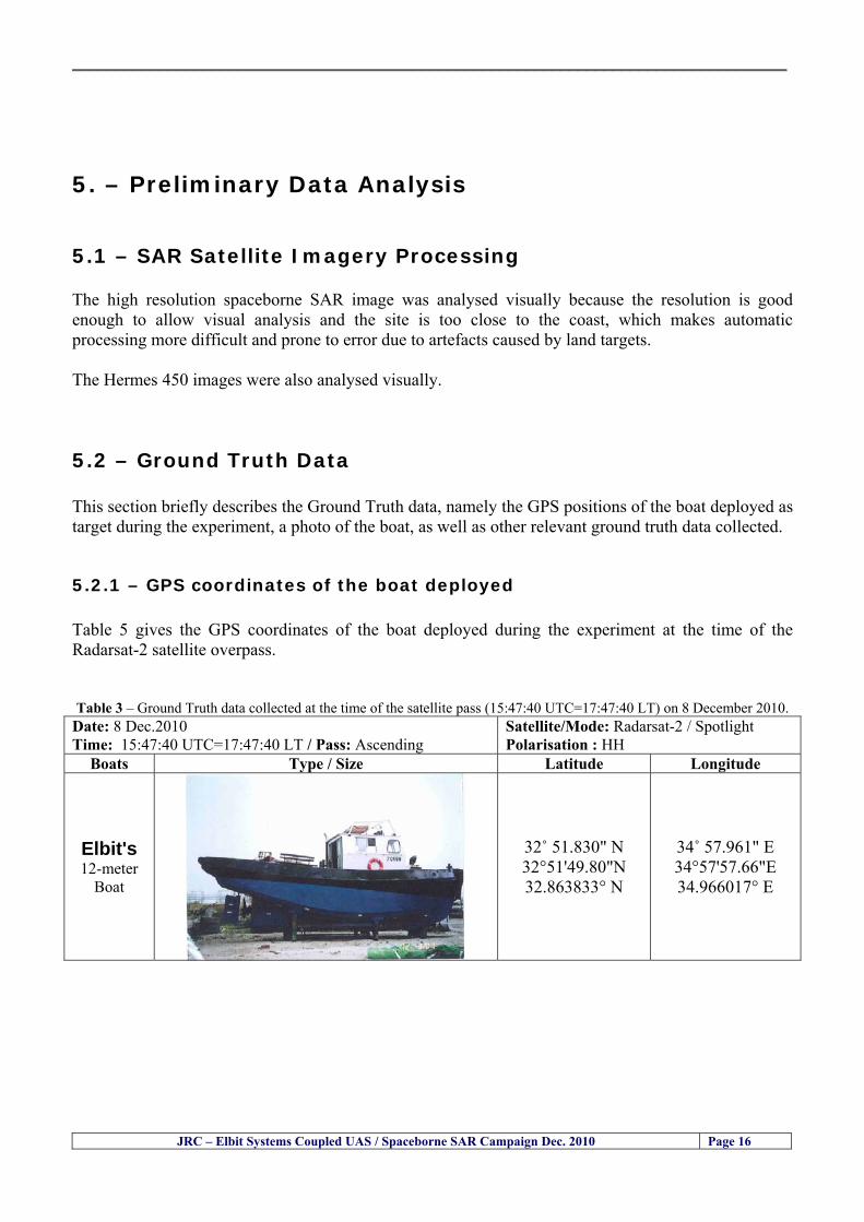
__________________________________________________________________________________
JRC ndash Elbit Systems Coupled UAS Spaceborne SAR Campaign Dec 2010 Page 16
5 ndash Preliminary Data Analysis
51 ndash SAR Satellite Imagery Processing The high resolution spaceborne SAR image was analysed visually because the resolution is good enough to allow visual analysis and the site is too close to the coast which makes automatic processing more difficult and prone to error due to artefacts caused by land targets The Hermes 450 images were also analysed visually
52 ndash Ground Truth Data This section briefly describes the Ground Truth data namely the GPS positions of the boat deployed as target during the experiment a photo of the boat as well as other relevant ground truth data collected
521 ndash GPS coordinates of the boat deployed Table 5 gives the GPS coordinates of the boat deployed during the experiment at the time of the Radarsat-2 satellite overpass Table 3 ndash Ground Truth data collected at the time of the satellite pass (154740 UTC=174740 LT) on 8 December 2010
Date 8 Dec2010 Time 154740 UTC=174740 LT Pass Ascending
SatelliteMode Radarsat-2 Spotlight Polarisation HH
Boats Type Size Latitude Longitude
Elbits 12-meter
Boat
32˚ 51830 N 32deg514980N 32863833deg N
34˚ 57961 E 34deg575766E 34966017deg E
__________________________________________________________________________________
JRC ndash Elbit Systems Coupled UAS Spaceborne SAR Campaign Dec 2010 Page 17
521 ndash HERMES 450 Ground Truth Data Table 4 shows the 12-meter Elbitacutes Boat as detected by the IR sensor of the Hermes 450 Table 4 ndash Hermes 450 Ground Truth Data Date 8 Dec2010 Time 154740 UTC=174740 LT
Platform Hermes 450
UAV Type Size Latitude Longitude
UAV Hermes
450
174730h 3284489947 N
174800h
3285089687 N
174730h 3498564048 E
174800h
3499338667 E
Elbits 12-meter
Boat UAV
Image
32˚ 51830 N 32deg514980N 32863833deg N
34˚ 57961 E 34deg575766E 34966017deg E
53 ndash Weather Conditions and Sea State The weather conditions in Haifa are summarized in Table 5 bellow
Table 5 ndash Wind speed wind direction and Temperature Time (IST) Temp Dew
Point Humidity Pressure Visibility Wind Dir
Wind Speed
Gust Speed Precip Events Conditions
550 PM 210 degC 130 degC 60 1017 hPa - North 111 kmh
31 ms - NA Clear
__________________________________________________________________________________
JRC ndash Elbit Systems Coupled UAS Spaceborne SAR Campaign Dec 2010 Page 18
Figure 10 gives the weather data (Temperature Barometric Pressure Wind Speed and Wind Direction) for Haifa Israel on 8 Dec 2010
Figure 10 ndash Weather data (Temperature Barometric Pressure Wind Speed and Wind Direction) for Haifa Israel on 8 Dec 2010
__________________________________________________________________________________
JRC ndash Elbit Systems Coupled UAS Spaceborne SAR Campaign Dec 2010 Page 19
54 ndash Verification of the Results This section briefly describes the verification of the targets detected in the spaceborne SAR image and in the Hermes 450 UAV using the ground truth data collected during the experiment
541 ndash Overview of the UAV Trajectory and the SAR Imagery Footprint Figure 11 gives an overview of the UAV trajectory the footprint of the SAR imagery and the area of the experiment near the port of Haifa The UAV trajectory is depicted in blue The large red rectangle is the footprint of the TerraSAR-X Stripmap The smaller red rectangle is the footprint of the Radarsat-2 Spotlight image
Figure 11 ndash Google Earth UAV trajectory during the experiment and footprinst of the SAR imagery ordered for the experiment Figure 12 is a zoom in of the previous image which allows a more detailed view of the UAV trajectory and of the port of Haifa Figure 13 is a zoom in of figure 12 It shows in more detail the UAV trajectory during the entire experiment and the port of Haifa in Israel
__________________________________________________________________________________
Figure 12 ndash Zoom in of the previous figure showing a more detailed view of the UAV trajectory and of the port of Haifa in Israel
Figure 13 ndash Zoom in of the previous figure showing a even more detailed view of the UAV trajectory and of the port of Haifa in Israel
JRC ndash Elbit Systems Coupled UAS Spaceborne SAR Campaign Dec 2010 Page 20
__________________________________________________________________________________
JRC ndash Elbit Systems Coupled UAS Spaceborne SAR Campaign Dec 2010 Page 21
542 ndash Targets Detected in the Radarsat-2 Spotlight Image Figure 14 illustrates the position of the Elbitrsquos boat used as target in the experiment at the approximate time of the SAR Satellite pass by 1547 UTC (1747 LT) The small photo of the boat shows the approximate position of the boat The two small planes show the positions of the UAV immediately before and after the SAR Satellite pass
Figure 14 ndash Google Earth positions of the elbitrsquos boat and the UAV (Hermes450) at the approximate time of the SAR Satellite overpass by 174740 UTC Figure 15 shows the corresponding SAR image (Radarsat-2 Spotlight) acquired during the experiment Pins 1 and 2 represent the positions of the UAV before and after the SAR satellite overpass Pin 3 illustrates the position of the Elbitacutes boat deployed at the time of the satellite overpass At this scale the SAR signature of the boat is not distinguishable from the sea clutter background However zooming in the SAR image the SAR signature can clearly be seen as illustrated in figure 12 The SAR image in figure 12 also shows several SAR signatures of large ships in the area at the time of the satellite overpass
__________________________________________________________________________________
JRC ndash Elbit Systems Coupled UAS Spaceborne SAR Campaign Dec 2010 Page 22
Elbit`s Boat
Figure 15 ndash On the background the SAR image with the two UAV positions before and after the satellite overpass (Pin1 and Pin2) and the Elbitacutes Boat position (Pin3) The small window over the SAR image shows a zoom in of the SAR image where the SAR signature of the Elbitacutes Boat can clearly be seen The top right are of the SAR image also shows SAR signatures of several large ships in the area at the time of the SAR satellite overpass Figure 16 shows the corresponding SAR image (Radarsat-2 Spotlight) acquired during the experiment and the UAV IR images of some of the targets Pins 1 and 2 represent the positions of the UAV before and after the SAR satellite overpass Pin 3 illustrates the position of the Elbitacutes boat deployed at the time of the satellite overpass At this scale the SAR signature of the boat is not distinguishable from the sea clutter background However zooming in the SAR image the SAR signature can clearly be seen as illustrated in figure 13 On the top left the UAV IR image of the Elbitrsquos Boat The SAR image in figure 13 also shows several SAR signatures of large ships in the area at the time of the satellite overpass On the centre left the UAV IR image of a large ship On the centre right the UAV IR image of a large ship On the bottom right the UAV IR image of a large ship All the UAV images were acquired at night in complete darkness from altitudes in the order of 5500 meters Nonetheless the quality and detail of the UAV images allows classification of the targets and in some cases the identification As it can be seen the potential of UAV for maritime surveillance is very promising During the experiment the UAV detected all the boats and ships in the area and tracked some of the boatsships to test the tracking capability The capability of detection and tracking targets is a critical capability for maritime surveillance
__________________________________________________________________________________
JRC ndash Elbit Systems Coupled UAS Spaceborne SAR Campaign Dec 2010 Page 23
Elbitacutes Boat
Elbit`s Boat
Figure 16 ndash Zoom-in of figure 15 with the UAV images of some targets On the top left the UAV IR image of the Elbitrsquos Boat On the centre left the UAV IR image of a large ship On the centre right the UAV IR image of a large ship On the bottom right the UAV IR image of a large ship Figure 17 shows a comparison of the SAR and UAV images with an optical photo taken in Haifa Israel a couple of hours before the SAR satellites overpass Most of the large ships were detected in the SAR image and some of these ships can be identified in the optical photo Some of the ships in the photo left the area before the SAR satellites overpass
__________________________________________________________________________________
JRC ndash Elbit Systems Coupled UAS Spaceborne SAR Campaign Dec 2010 Page 24
Figure 17 ndash Photo taken in Haifa Israel a couple of hours before the SAR satellites overpass This phot shows the large ships moored in the area Most of these large ships were detected in the Radarsat-2 image As expected their positions and orientations were slightly different at the time of the satellite overpass
Elbitacutes Boat
Elbit`s Boat
__________________________________________________________________________________
JRC ndash Elbit Systems Coupled UAS Spaceborne SAR Campaign Dec 2010 Page 25
Figure 18 ndash Photo taken in Haifa Israel a couple of hours before the SAR satellites overpass This phot shows the large ships moored in the area Most of these large ships were detected in the Radarsat-2 image As expected their positions and orientations were slightly different at the time of the satellite overpass Figure 18 illustrates the SAR image and the corresponding google earth image of a small pier in the port of Haifa In the SAR image due to several artefacts it is not possible to detect the 7 small boats moored to the small pier The UAR IR image of the same area clearly shows the 7 small boats with impressive detail taking into account that the image was acquired from an altitude of about 5500 meters A zoom in of the same UAV IR image is shown in figure 19 As it can be seen although the image was acquired from an altitude of about 5500 meters the 7 small boats can be clearly seen with enough detail to allow classification of the type of boat A UAV flight at lower altitude would probably giver a lot more detail and eventually allow the identification of the small boats
__________________________________________________________________________________
JRC ndash Elbit Systems Coupled UAS Spaceborne SAR Campaign Dec 2010 Page 26
Figure 19 ndash UAV IR image of a small pier in the port of Haifa Israel where 7 small boats can be seen with enough detail to allow classification This image was acquired from an altitude of about 5500 meters in the dark
__________________________________________________________________________________
55 ndash Quantitative Analysis of the Spaceborne SAR Image In order to allow a quantitative analysis of the data the spaceborne SAR image was calibrated using ESArsquos NEST software package version 4B The input was the SAR image acquired and the output was the Radiometric Calibration (Sigma Naught (σdeg)) expressed in terms of intensity and in decibel (dB) the Radar Brightness (βdeg) and the Radiometric Normalisation (gamma naught (γdeg))
551 ndash Radarsat-2-Spotlight 08Dec2010 (154740 UTC) Haifa Israel Figure 20 illustrates the Intensity band of a subset of the Radarsat-2Spotlgiht image (08Dec2010)
Figure 20 ndash Radarsat-2 Spotlgiht image (08Dec2010) ndash Sigma Naught (Intensity) band
JRC ndash Elbit Systems Coupled UAS Spaceborne SAR Campaign Dec 2010 Page 27
__________________________________________________________________________________
Figure 21 illustrates the Sigma Naught Coefficient of the Radarsat-2 Spotlgiht image (08Dec2010) expressed in terms of intensity and decibel (dB)
Figure 21 ndash Radarsat-2 Spotlgiht image (08Dec2010) - On the left the Sigma Naught (σdeg) (intensity) and on the right the Sigma Naught (σdeg) (dB)
ormalisation amma Naught (γdeg)) of the Radarsat-2 Spotlgiht image (08Dec2010) expressed in dB
-2 Spotlgiht image (08Dec2010) - On the left the Beta Naught (βdeg) and on the right the Gamma Naught (γdeg) (dB)
Figure 22 illustrates the Radar Brightness (Beta Naught (βdeg)) and the radiometric n(G
Figure 22 ndash Radarsat
JRC ndash Elbit Systems Coupled UAS Spaceborne SAR Campaign Dec 2010 Page 28
__________________________________________________________________________________ Figure 23 shows the Sigma Naught (σdeg) in dB after some colour manipulation and the histogram of the Sigma Naught (σdeg) image
Figure 23 ndash Radarsat-2 Spotlgiht image (08Dec2010) - On the top left the Sigma Naught (σdeg) after colour manipulation to enhance the targets and on the top right the corresponding histogram On the bottom we can see the histogram of the image
Table 6 gives the statistics of the Sigma Naught (σdeg) Radarsat-2 Spotlgiht image (08Dec2010) The Sigma Naught (σdeg) range from -72897 dB up to 23465 dB The Mean value is -16855 dB the Median is -16594 dB and the standard deviation is 7077 dB
JRC ndash Elbit Systems Coupled UAS Spaceborne SAR Campaign Dec 2010 Page 29
__________________________________________________________________________________
JRC ndash Elbit Systems Coupled UAS Spaceborne SAR Campaign Dec 2010 Page 30
Table 6 ndash Statistics of the Radarsat-2 Spotlgiht image (08Dec2010) (154740 UTC)
Statistics Values Unit Only ROI-Mask pixels considered Number of pixels total Number of considered pixels Ratio of considered pixels
No 322394283 322394283
1000
Minimum Maximum
-728974609375 234655818939209
intensity_db intensity_db
Mean Median Std-Dev Coefficient of Variation
-16855686580177853 -1659462338617847 707796800831575
07888765273432338
intensity_db intensity_db intensity_db intensity_db
Checking the radar backscattering coefficient of some targets (small boat and some large ships) detected in the Radarsat-2 Spotlight image we get values ranging from -0379 dB up to 23455 dB The analysis of the Sigma Naught values (σdeg) of the targets and the area around the targets shows a significant contrast
56 ndash Summary of the Preliminary Analysis of the Spaceborne SAR Image This experiment involved two spaceborne SAR images namely a TerraSAR-X Stripmap and one Radarsat-2 Spotlight The TerraSAR-X image was not delivered by DLR due to technical problems The Elbitrsquos boat deployed during the experiment was detected in the Radarsat-2 Spotlight image Several other targets including a set of large ships were also detected Table 7 summarises the characteristics of the SAR image acquired and the targets detected
Table 7 ndash List of SAR Satellite Images acquired during the experiment and detected boats ISRAEL (HAIFA)
Date Time Place Satellite Mode Ground Truth Data Detected Boats
08Dec2010 (PM) Haifa - Israel Radarsat-2 Spotlight GPSPhotosMovies 1 small boat deployed + 9 large ships
Table 8 gives the minimum and maximum Sigma Naught (σdeg) of the targets detected in each SAR image
Table 8 ndash Minimum and maximum Sigma Naught (σdeg) of the targets detected in each SAR image
Date Time UTC (LT)Pass Satellite Image Mode Polarisation Sigma Naught (σdeg) Min Max
29Oct2010528UTC(728AM LT) DES Radarsat-2 Spotlight HH --0379 dB 23455 dB The SAR signatures of the boats deployed were very weak Some possible reasons to explain such weak signatures are the sea state the wind speed the incidence angle and the type and materials Another possible reason is the processing at DLR
__________________________________________________________________________________
JRC ndash Elbit Systems Coupled UAS Spaceborne SAR Campaign Dec 2010 Page 31
6 ndash Preliminary Conclusions The analysis of the results of this coupled UASSpaceborne SAR experiment shows a promising potential for the use of UAS for maritime surveillance UAS can be integrated into the airborne building block of maritime surveillance systems to complement the existing assets increase system performance and improve the overall maritime domain awareness The main perceived maritime security and safety threats comprise piracy terrorist and military threats weapons proliferationsmuggling drugs trafficking illegal immigration unlawful use of containers attacks to critical infrastructures and illegal fishing The main maritime security and safety gaps include a lack of technologies with the capability of detecting small targets (eg small boats) a lack of wide area and persistent maritime surveillance a lack of coordination and information sharing limited interoperability a lack of containers security a lack of persistent surveillance of critical infrastructures and early warning systems Unmanned Aircraft Systems (UAS) are an emerging technology with strong potential to mitigate the above mentioned threats by filing in the main maritime security and safety gaps listed earlier For instance the wide range of potential applications of UAS to maritime surveillance includes but is not limited to
bull detection classification and identification of small boats bull persistent maritime surveillance bull use as communications relays bull persistent surveillance of critical infrastructures bull early warning systems bull COMINT and ELINT collection etc
Table 11 illustrates the mapping of maritime securitysafety threats vs gaps and summarises the main potential applications of UAS to maritime surveillance The above mentioned potential applications of UAS to the Maritime Domain will be addressed in turn in more detail next bull Detection classification and identification of small boats ndash The capability of detecting classifying and identifying small targets (eg small boats) is among the key technologies required to improve maritime domain awareness This capability is critical to mitigate piracy illegal immigration drugs trafficking weapons smuggling illegal fishing terrorism and critical infrastructure Unmanned Aircraft Systems (UAS) provide this capability more efficiently and at a lower cost than any other existing technology bull Persistent maritime surveillance ndash With the continuous improvements of UAS technologies such as platforms sensors collision avoidance systems command and control systems telecommunications etc UAS are increasing their autonomy endurance and flexibility These characteristics are very important for persistent maritime surveillance UAS can be launched from land ships aircraft and technologies to launch UAS from submarines are currently under development UAS have distinct advantages over other existing technologies for persistent maritime surveillance in terms of autonomyendurance (the Global Surveyor has an autonomy of 1 week) cost (eg as the autonomy of UAS increases the number of staff required to operate UAS decreases) risk (eg if the UAS crashes the crew is not at risk) flexibility (eg they can be launched from a ship reducing the time to reach potential threats) etc
__________________________________________________________________________________
JRC ndash Elbit Systems Coupled UAS Spaceborne SAR Campaign Dec 2010 Page 32
bull Communications relays ndash UAS are being used as communication relays mainly in military context but have the potential to play a similar role in Civil context in several situations such as to replace satellite communications or as a redundant system over any location on Earth The main advantages of using UAS as communication relays is that airborne communication relays mitigate kinetic and noise jamming threats to satellite communications uplinks by providing an alternative set of links either directly to surface-based terminals or to satellites beyond the range of threats They are less susceptible to noise jamming threats than satellites because an adversary has to detect geolocate and track the airborne asset and operate within line of sight of the receive antenna main beam bull Persistent surveillance of critical infrastructures ndash The security of critical infrastructures such as nuclear power plants refineries ports etc requires persistent surveillance UAS can play an important role in providing persistent surveillance over critical infrastructures and over a wide area around the critical infrastructure Some advantages of UAS over other existing technologies such as ground-based assets (eg video cameras alarm systems manned aircraft etc) comprise the security of the UAS (eg hardly can be damaged or switched off as any ground-based asset) the area covered by a UAS (eg it is larger than the area covered by any ground-based asset) the cost (eg UAS is cheaper than manned aircraft with similar capability) etc bull Early warning systems ndash UAS have the potential to be used as part of an integrated system of systems for early warning A UAS can provide information about a given area at a fraction of the cost of alternative means Formation flying of UAS can cover a wide maritime area It is reasonable to assume that in a foreseeable future with the advent of UAS with increased autonomy the operations cost of UAS will likely decrease making them increasingly more attractive bull COMINT and ELINT collection ndash SIGNal INTelligence (SIGNINT) can be divided into two categories namely COMINT and ELINT COMINT stands for Communication Intelligence and ELINT for Electronic Intelligence Collection of COMINT is passive Exploitation of COMINT requires a human operator which implies COMINT UAS are suitable for COMINT and ELINT collection in different scenarios The relatively reduced amount of data collected and analysed during this experiment and the lessons learned do not allow drawing final conclusions about the feasibility of using Unmanned Aerial Systems (UAS) for maritime surveillance However this experiment allowed hands-on experience with UAS technologies and significantly improved the awareness for its applications to maritime surveillance and related issues involved including its potential the feasibility as well as the limiting and enabling factors These different aspects will now be analysed in turn in the next sections Table 11 illustrates the mapping of the main maritime security threats and gaps as well as the main priorities in terms of the different technologies involved in maritime surveillance For each maritime threat the technologies required to fill in each gap is indicated and its priority is expressed in a range of numbers (1 to 3 1 = Maximum Priority 2 = Medium Priority 3 = Low Priority) and colours (Red = Maximum Priority Orange = Medium Priority Green = Low Priority) The main technologies involved in maritime surveillance are listed on the bottom of figure 4 and are reproduced here for convenience of the reader 1- Reporting Systems 2- Sensors 3- Platforms 4- Communications 5- Data Fusion amp Sharing 6- Intelligence and 7- Databases For example the mitigation of the main threat Piracy requires filling in several maritime security gaps (eg lack of persistent surveillance lack of wide-are maritime surveillance lack of small boat detection lack of Early Warning Systems and lack of Information Sharing with maximum priority (1- Red) and among the required technologies listed are UAS LTAAV GEO-HR etc Concerning the remaining two gaps (Limited Interoperability and Containers Security) they are less relevant to mitigate Piracy hence the priority for Limited Interoperability is 2-Orange and for Containers Security is 3- Green
__________________________________________________________________________________ Table 9 ndash The Main Maritime Security and Safety Threats vs Gaps and the technologies that can be used to mitigate them
Maritime Security Main Threats GapsGapsrarr
darrThreats
Lack o f Risk As sessmentCapab ility
La ck of Persiste nt
Surveilla nce
La ck of Wid e-Area su rve illanc e
La ck of Small Boat De tecti on
Lack o f Earl y Warn ing Sys tems
L ack of In forma tion
Sh arin g
L imi ted In terop era bility
Lac k of Co ntai ners
Se cur ity
bull PiracyUAS LTAVG EO-
HR + UAS LT AVGEO-
HR + SAR GEO-HR
+ UAS USV LTAV
+ UAS LTAV
+ Coord in ationamp Sharing +
Inter opera bilityOptimisation +
1 2 3 5 6 7 1 2 3 5 6 7 1 2 3 5 6 1 2 3 123456 4567 1234567 1234567
bull Terro rismUAS LTAVG EO-
HR + UAS L TAV GEO-HR +
SAR AISGEO-HR +
UAS USV LTAV+
Intelligence+
Inte lligen ce+
Inter opera bilityOptimisation +
Intelligence+
1 2 3 5 6 7 1 2 3 5 6 1 2 3 5 6 1 2 3 123456 4567 1234567 1234567
bull Wea pon s ofM ass Dest ru ctio n Smugg ling
UAS LTAVG EO-HR +
UAS LT AVGEO-HR +
SAR AIS+
UAS USV LTAV+
Intelligence+
Inte lligen ce+
Intelligence+
Intelligence+
1 2 3 5 6 7 1 2 3 5 6 1 2 3 5 6 1 2 3 123456 4567 1234567 1234567
bull Drug sTraffic king
UAS LTAVG EO-HR +
UAS LT AVGEO-HR +
SAR AIS+
UAS USV LTAV+
Intelligence+
Inte lligen ce+
Intelligence+
Intelligence+
1 2 3 5 6 7 1 2 3 5 6 1 2 3 5 6 1 2 3 123456 4567 1234567 1234567
bull Illega lImmigratio n
UAS LTAVG EO-HR +
UAS LT AVGEO-HR +
SAR AIS+
UAS USV LTAV+
Intelligence+
Inte lligen ce+
Intelligence+
Intelligence+
1 2 3 5 6 7 1 2 3 5 6 1 2 3 5 6 1 2 3 123456 4567 1234567 1234567
bull Critic alI nfrastruc tureSecu rit y
UAS LTAVG EO-HR +
UAS LT AVGEO-HR +
SAR AIS+
UAS USV LTAV+ + Inte lligen ce
+ Intelligence
+ Intelligence
+
1 2 3 5 6 7 1 2 3 6 1 2 3 5 6 1 2 3 123456 4567 1234567 1234567
bull Illega lFish ing
UAS LTAVG EO-HR +
AI S+SAR UASLTAV +
SAR AIS GEO-HR+
UAS USV LTAV+
Intelligence+
Inte lligen ce+
Intelligence+
1 2 3 5 6 7 1 2 3 5 7 1 2 3 5 6 1 2 3 123456 4567 1234567
bull Un lawf ul Use of Co nta iners
(Secur ity)
UAS LTAVG EO-HR +
GPS Tr acking+
Intelligence+
Inte lligen ce+
GPS Int rusion Det ection Se al
1 2 3 5 6 7 4 6 7 1 2 3 5 6 1 2 3 123456 4567 1234567 1234567
(-) Priority (+) Not Rel evant
SURVEILLANCETECHNOLOGIES
1- Reporti ng Systems
2 -Sensors 3 -P latforms 4 - Communications 5- Data Fusionamp Sharing
6 -I ntelli gence 7 -Databases
JRC ndash Elbit Systems Coupled UAS Spaceborne SAR Campaign Dec 2010 Page 33
__________________________________________________________________________________
JRC ndash Elbit Systems Coupled UAS Spaceborne SAR Campaign Dec 2010 Page 34
61 ndash Hands-on experience with UAS technologies and its applications to maritime surveillance This coupled UASSpaceborne SAR campaign was a unique opportunity to acquire further handsndashon experience with UAS technologies and learn about the main issues related to its applications to maritime surveillance From the planning phase up to the execution of the UAS flight and landing there are several factors that need to be carefully analysed and taken into account A summary of the main issues identified in this experiment is given next 1- Selection of the Experiment Area Authorisation to Fly ndash For the time being UAS can only be flown in restricted areas usually under control of national authorities often the military This is due to the risks that a UAS can pose to human life and property In the present case an area under the authority of the Israeli Civil Aviation Authority was selected The authorisation to fly was not easy to obtain because the selected area is under the authority of the Civil Aviation Authority Figure 24 indicates the area of the experiment in Haifa Israel 2- UAS Communications Issues ndash The Hermes 450 was flown in Line-of-Sight (LOS) since it was close to the coast For BLOS (Beyond Line-of-Sight) operation satellite communications are required 3- Synthetic Aperture Radar (SAR) ndash The specific model Hermes 450W used in the experiment had no SAR sensor installed However a SAR sensor can be installed A SAR sensor is important for maritime surveillance since it allows 247 operations regardless of the weather conditions 4- Automatic Identification System (AIS) Receiver ndash The Hermes 450 used in this experiment was not equipped with an AIS receiver For maritime surveillance operations an AIS receiver is a very important tool since it allows the automatic identification of most ships allowing the UAS to concentrate on non-identified ships
__________________________________________________________________________________
Figure 24 ndash The area of the experiment is indicated by the GPS Trajectory of the UAV
62 ndash Potential of UAS for Maritime Surveillance UAS technologies are relatively recent and involve a wide range of fields spanning from aeronautics and sensors technologies to satellite communications and other engineering disciplines Innovations in each of the fields involved are emerging by the day UAS still have a long way to go before they become mature and their use fully operational For the time being UAS are mainly used for military applications However a large number of non-military UAS applications have been identified by stakeholders and there are several studies and demonstration flights foreseen for the near future Maritime surveillance is one of the most challenging and promising fields of application of UAS The challenges are due to the very demanding conditions under which the UAS must operate over sea and the requirements for safe operation
JRC ndash Elbit Systems Coupled UAS Spaceborne SAR Campaign Dec 2010 Page 35
__________________________________________________________________________________
JRC ndash Elbit Systems Coupled UAS Spaceborne SAR Campaign Dec 2010 Page 36
The present UAS experiment has unveiled some of the potential of UAS for maritime surveillance The UAS tests performed during this experiment include
1 ndash Detection of a Small rubber Boat and a Fishing Ship 2 ndash Tracking of a Small Boat and a Fishing Ship 3 ndash Classification of a Small Boat and a Fishing Ship 4 ndash Identification of a Small Boat and a Fishing Ship 5 ndash Detection and Tracking of People on the Beach
Despite the operational requirement that prevented the UAS from flying bellow 3km the experiment has confirmed the capability of UAS for small boat detection tracking and classification as well as the capability for people detection and tracking Concerning the identification of the targets the characteristics of the images acquired during this mission suggest that flying at lower altitudes the UAS images would allow the identification of the targets The UAS images can be seen from Figure 15 to 20
621 ndash Advantages of UAS for maritime Surveillance Some of the advantages of using UAS for maritime surveillance have been described in the literature and are summarized bellow
1- One potential benefit of UAS is that they could fill in a gap in current maritime surveillance by improving coverage
2- The range of UAS is a significant asset when compared to border agents on patrol or stationary surveillance equipment
3- Eletro-Optical InfraRed (EOIR) sensors (cameras) can identify small size objects from very high altitudes (high resolution)
4- UAS can provide precise and near-real-time imagery to a ground control operator who would then disseminate that information so that informed decisions regarding the deployment of border patrol agents can be made quickly
5- Long endurance UAS used along the border can fly for more than 30 hours up to several days without having to refuel compared with manned helicopterrsquos average flight time of just over 2 hours
6- The ability of UAS to loiter for prolonged periods of time has important operational advantages over manned aircraft
7- The longer flight times of UAS means that sustained coverage over a previously exposed area may improve maritime security
8- The range of UAVs is a significant asset when compared to border agents on patrol or stationary surveillance equipment Nevertheless the extended range and endurance of UAVs may lessen the burdens on human resources at the borders
9- UAS accidents do not risk the lives of pilots as do the helicopters and aircraft currently used by Coast Guards for border patrolling
__________________________________________________________________________________
JRC ndash Elbit Systems Coupled UAS Spaceborne SAR Campaign Dec 2010 Page 37
622 ndash Possible Drawbacks of using UAS for maritime Surveillance UAS also have disadvantages some of them are briefly described next
1- There have been concerns regarding the high accident rate of UAS which can be multiple times higher than that of manned aircraft Because UAS technology is still evolving there is less redundancy built into the operating system of UAS than of manned aircraft and until redundant systems are perfected mishap rates are expected to remain high
2- If control systems fail in a manned aircraft a well-trained pilot is better positioned to find the source of the problem because of hisher physical proximity If a UAS encountered a similar system failure or if a UAS landing was attempted during difficult weather conditions the ground control pilot would be at a disadvantage because he or she is removed from the event Unlike a manned pilot the remote pilot would not be able to assess important sensory information such as wind speed
3- Inclement weather conditions can also impinge on a UAS surveillance capability especially UAS equipped with only an EO camera and Forward Looking Infrared Radar (FLIR) because cloudy conditions and high humidity climates can distort the imagery produced by EO and FLIR equipment The effects of extreme climatic or atmospheric conditions on sensors reportedly can be mitigated with the outfit of one synthetic aperture radar (SAR) system and a moving target indicator (MTI) radar However adding SAR and MTI to a UAS platform would increase the costs associated with using UAS
4- Depending on the type of UAS the costs of operating a UAS can be higher than the costs of operating a manned aircraft This is because some types of UAS require a significant amount of logistical support and specialized operator and maintenance training Operating one UAS may require a crew of up to 20 support personnel The high comparative costs of operating some sophisticated types of UAS may be offset somewhat by their comparatively lower unit costs
63 ndash Main Limiting Factors Preventing the Use of UAS Several pre-requisites must be satisfied to render the UAS a viable cost-effective and regulated alternative to existing resources Major civil and commercial market barriers include
Single European Sky Sense and Avoid technologies Command and Control Technologies Reliability Communications (Bandwidth LOS BLOS)
Lack of airspace regulation that covers all types of UAV systems (encompassing lsquosense and avoidrsquo airspace integration and airworthiness issues)
Affordability - price and customization issues (eg commercial off-the-shelf open modular architecture) Lack of efforts to establish joint customer requirements (although this is gradually changing) Liability for civil operation Capacity for payload flexibility Lack of sufficient secure non-military frequencies for civil operation Perceived reliability (eg vehicle attrition rate vs manned aircraft) Operator training issues Recognitioncustomer perception of the UAV market Technology developments for multi-mission capability
__________________________________________________________________________________
64 ndash UAS Key Enabling Technologies Figure 25 illustrates the components of a typical UAV System showing some of the capabilities needed and the enabling technologies required for performing a given mission Any UAV mission involves many capabilities and technologies Due to the depicted system complexity the main key players such as the US Department of Defense (DoD) and other agencies have started to use the term Unmanned Aerial System (UAS) in place of UAV
Figure 25 ndash Unmanned Aerial Vehicle System Enabled by Autonomous Mission Management Reliable Flight Systems Navigation Accurate Systems Terrain Avoidance Power and Propulsion Some UAS key enabling technologies are listed below
Autonomous Mission Management Collision Avoidance Intelligent System Health Monitoring
Reliable Flight Systems Sophisticated Contingency Management Intelligent Data Handling and Processing Over-the-Horizon Communication Network-Centric Communication Open Architecture Power and Propulsion Navigation Accurate System Technology Enhanced Structures
JRC ndash Elbit Systems Coupled UAS Spaceborne SAR Campaign Dec 2010 Page 38
__________________________________________________________________________________
JRC ndash Elbit Systems Coupled UAS Spaceborne SAR Campaign Dec 2010 Page 39
Table 12 gives a more detailed description of other critical technologies for emerging autonomous UAV systems both civil and military Most of the technologies mentioned in Table 12 apply both to civil and military UAV systems Table 10 ndash Key Enabling Technologies (from SG75 study on autonomous systems)
Critical Technologies Decision Making Software
bull Fuzzy-based decision making bull Knowledge-based system bull Case-based reasoning bull Self-learning techniques bull Decision tree evaluation bull ReasoningInferring bull Probabilisticstochastic reasoning
Prediction Algorithms bull Predictive pathintent algorithms bull Short reaction algorithm bull Effectiveness evaluation
Status Assessment Software bull Internal status analysis bull Self-orientation
Situation Analysis Software bull Situation analysis bull Environmental analysis bull External status analysis
Modelling Software bull Air vehicle modelling algorithms bull Sensor modelling algorithms bull Scenario generation bull Threat system modeling bull Attack simulation bull Mission success optimisation model bull Simulation
Sensor Processing Software bull Sensor fusion bull Area of interest identification bull Automatic target recognition
Adaptive and Self-learning Systems bull Failure self-compensation
Attack Planning Software bull Attack plans and tactical alternatives bull Plan change impact identification
Weapon Engagement Procedure Software bull Weapon engagement algorithms
Mission Plan Update Software bull Route planning system bull Payload plan management system bull Mission Success Optimisation model
Path Optimisation Software bull Optimal trajectory planning bull Path Optimisation System
Targeting Software bull Target tracking bull Target prioritisation
Platform Technologies bull Obstacle detection and avoidance (airborne) bull Obstacle detection and avoidance (ground) bull Improved autopilot bull Speech recognition
Figure 26 summarises system element designs needed to transition from current to next-generation autonomous UAV systems for civilian and military UAS
__________________________________________________________________________________
Figure 26 ndash System Element Designs Needed to Transition from Current to Next-Generation Autonomous UAV Systems These new paradigms are a combination of system attributes and technological capabilities For instance the data fusion secure anti-jam and coordinated multi-vehicle control require technological development as well as specific system development to bring full maturity to unmanned systems Finally very small Micro UAVs (MAVs) and relatively large sophisticated UCAV systems are examples of the range of UAVs that are applying the new platforms payloads onboard processing communications etc to create next generation automated UAVs It is with these new platforms payloads etc that both UCAVs and MAV will be able to address similar operational challenges including
Mixed operation with other assets bull Deconfliction collision avoidance C4I integration
Operation over populated areas bull Safety issues Need to reduce reliance on communications bull UCAV ndash countermeasures bull MAV ndash limited size and power bull Limited line of sight environment Need a fully integrated system bull MAV propulsionpower generation still critical bull Operator machine interface critical bull All weather operations bull Survivability
JRC ndash Elbit Systems Coupled UAS Spaceborne SAR Campaign Dec 2010 Page 40
__________________________________________________________________________________
JRC ndash Elbit Systems Coupled UAS Spaceborne SAR Campaign Dec 2010 Page 41
65 ndash Mission Readiness
651 ndash Mission Readiness Summary This section summarises civil UAV mission readiness The purpose of Mission Readiness is to assess the readiness status of the different technologies involved in UAS In the present case this civil UAV mission readiness based on technology maturation forecasts that meet or exceed the desired or required capabilities identified by the user community Figure 27 summarises the mission readiness time forecasts for the different technologies The technologies annotated with an asterisk () are shown within the figure with maturation forecasts based on development targets expressed in the US Department of Defencesrsquo UAV Roadmap document The purpose of the chart is to be able to identify when the capability to fly a particular mission can be expected as a function of time The left-most end is the least probable and the right end the most probable timeframe
Figure 27 ndash Technology Maturation Summaries in Terms of Mission-Derived Capabilities
__________________________________________________________________________________
JRC ndash Elbit Systems Coupled UAS Spaceborne SAR Campaign Dec 2010 Page 42
66 ndash Small Boat Detection in SAR Satellite Imagery The use of spaceborne SAR imagery for small boat detection requires additional small boat detection experiments under different conditions using different methods It is not possible to draw final conclusions based on a limited number of small boat detection experiments which are not representative of the multiple possible scenarios
67 ndash Limitations of current State-of-the-Art SAR Satellite technology The main limitations of current State-of-the-Art spaceborne SAR imagery for maritime surveillance in particular aimed at small boat detection are 1 - SAR satellites repeat cycles do not allow the coverage of the same area at the required time intervals Constellations of SAR satellites could be a solution 2 - The conflict between resolution and image swath High resolution is required to detect small boats However the high resolution images have small swaths Maritime surveillance with high resolution images would require a large number of images to cover wide maritime areas which is very expensive and for the time being technically not feasible Intelligence data can play an important role by indicating an approximate position of suspicious non cooperative targets therefore reducing the surveillance area which can then be imaged using high resolution images 3- Spaceborne high resolution SAR imagery acquisition times are long enough to allow significant motion of the target during the acquisition time degrading the quality of the image Further research efforts are needed to develop new sensors and platforms As far as sensors are concerned shorter integration times are needed to prevent the blurring effect caused by the motion of the targets Regarding the platforms more platforms are needed to allow lower repeat cycles and improved coverage
__________________________________________________________________________________
JRC ndash Elbit Systems Coupled UAS Spaceborne SAR Campaign Dec 2010 Page 43
7 ndash Plans for Future Work The controlled experiments carried out by the EC-JRC together with Elbit Systems in Haifa-Israel comprised the deployment of a UAS (Hermes-450) and one small 12-meter boat A Radarsat-2 Spotlight image was acquired and several images collected by the Hermes-450 The experiment unveiled the potential of UAS for maritime surveillance in particular for detection tracking classification and possible identification of small targets The UAS was able to detect track and classify small targets such as small boats For low UAS altitude flights identification may be possible in some cases The small 12-meter boat was detected in the spaceborne SAR image The small boat detection trials carried out by the JRC were very successful since most small boats deployed during the experiments were detected in different sea states wind speeds and geographical locations The several small boat detection campaigns conducted by the EC-JRC seem to suggest that the probability of detection of small boats in spaceborne SAR images strongly depends on factors such as the sea state the wind speed the type of boat (shape and materials) the weather conditions among other factors The results of the experiments conducted thus far are not enough to draw final conclusions about the feasibility of using spaceborne SAR imagery for small boat detection However the experiments have an overall positive outcome because they indicate that under suitable sea state and wind speed conditions it is possible to detect small boats using spaceborne SAR The estimation of the probability of detection of small boats in spaceborne SAR images requires a large number of experiments under different circumstances (eg sea state wind speed characteristics of the targets image type and mode etc) Future plans include additional UAS experiments to asses its potential for maritime surveillance
Acknowledgements ndash The authors would like to express their gratitude to Elbit Systems for their cooperation logistical support and assets deployed without which the present coupled UASSAR Satellite Small Boat Detection Campaign would have not been possible
__________________________________________________________________________________
JRC ndash Elbit Systems Coupled UAS Spaceborne SAR Campaign Dec 2010 Page 44
REFERENCES [1] Elbit Systems ldquoUAV Elbit Systems Proposal for Unmanned Aerial Vehicle (UAV) flight to
collect Ground Truth data during a Maritime Surveillance Campaign and demonstrate UAV capabilities for Maritime Surveillancerdquo 2010
[2] ndash Cheryl Yuhas Suborbital Science Program Manager NASA Science Mission Directorate ldquoEarth Observations and the Role of UAVs A Capabilities Assessment Version 11rdquo Civil UAV Assessment Team httpwwwnasagovcentersdrydenresearchcivuavindexhtml August 2006
[3] ndash Document NIAG (SG75) NATO Industrial Advisory Group Study Group 75 Pre-Feasibility Study on UAV Autonomous Operations 2004
[4] ndash United States Department of Defence (DoD) Directive 50001 ldquoThe Defense Acquisition Systemrdquo and DoD Instruction 50002 ldquoOperation of the Defense Acquisition Systemrdquo
[5] ndash Mr James Ramage Mr Massimo Avalle Dr Erik Berglund Dr Luigi Crovella Mr Robert Frampton Dr Uwe Krogmann Mr Christian Ravat Mr Mike Robinson Dr Axel Schulte Dr Scott Wood ldquoRTO-TR-SCI-118 - Automation Technologies and Application Considerations for Highly Integrated Mission Systemsrdquo RTO-TR-SCI-118 AC323(SCI-118)TP204 January 2009
[6] Victor MG Silva Gilles Jurquet Gabriel Marchalot Maria TG Calzado Txema Soroa Juan Sancho Adam Koubek Harm Greidanus and Claudio Savarino ldquoWide Maritime Area Airborne Surveillance (WIMA2S) WP5 Final Reportrdquo WIMAAS WP5 FP7 Project 2008-2011 - ISBN-978-92-79-22801-8 (print) 978-92-79-22802-5 (PDF) ISSN-1018-5593 (print) 1831-9424 (online) EC-JRC Scientific Report JRC 70093 2012
[7] Victor MG Silva and Harm Greidanus ldquoSpaceborne SAR Small Boat Detection Campaign in Portugal and Spainrdquo EUR 25281 EN ISBN 978-92-79-22553-6 ISSN 1831-9424 (online) EC-JRC Scientific Report JRC68160 2012
[8] Goncalves Da Silva V Van Wimersma Greidanus H Hejmanowska B Loudjani P ldquoUAS Applications With Societal Benefits ndash JRCrsquos UAS-Related Activitiesrdquo 2011-2012 UAS Yearbook - UAS Unmanned Aircraft Systems - The Global Perspective 9 (9) 2011 p 127-129 JRC66600
[9] Goncalves Da Silva V Van Wimersma Greidanus H ldquoSmall boat detection using TerraSAR-X and Radarsat2 satellite imageryrdquo 4th TerraSAR-X Science Team Meeting 14 February 2011 DLR Oberpfaffenhofen (Germany) German Aerospace Center (DLR) (Organiser) 2011 JRC63663
[10] V Silva Harm Greidanus ldquoJRC - SAR Satellite Small Boat Detection Campaign - Portoroz ndash Sloveniardquo - ISBN-13 978-92-79-21476-9 ISSN (online) 1831-9424 EC-JRC Scientific Report JRC66835 2011
[11] V Silva Harm Greidanus ldquoJRC - SAR satellite small boat detection campaign - Algarve Portugalrdquo - ISBN-13 978-92-79-21265-9 ISSN (online) 1831-9424 ISSN (print) 1018-5593 EC-JRC Scientific Report JRC66631 2011
[12] ndash Goncalves Da Silva V Van Wimersma Greidanus H ldquoJRC-Frontex Spaceborne SAR Small Boat Detection Campaign ndash Italy amp Spainrdquo - ISBN-13 978-92-79-22213-9 ISSN (online) 1831-9424 EC-JRC Scientific Report JRC67517 2011
[13] - PW Vachon SJ Thomas J Cranton HR Edel and MD Henschel Validation of ship detection by the RADARSAT synthetic aperture radar and the Ocean Monitoring Workstation Canadian Journal of Remote Sensing 26(3)200ndash212 2000
[14] - Crisp D (2004) The state-of-the-art in ship detection in Synthetic Aperture Radar imagery DSTO Information Sciences Laboratory Australia
[15] - Joint Research Centre (JRC) of the European Community mdash IMPAST and DECLIMS web site httpintelligencejrcceceuintmarinefishindexhtm
[16] - McCandless SW Jackson CR (2004) Principles of Synthetic Aperture Radar Synthetic Aperture Radar Marine Users Manual NOAA Washington pp 1-23
[17] - Greidanus H (2008) Satellite Imaging for Maritime Surveillance of the European Seas Remote Sensing of the European Seas 343-358
European Commission
EUR 25346 EN --- Joint Research Centre --- Institute for the Protection and Security of the Citizen
Title JRC --- Elbit Systems Coupled UAS and Spaceborne SAR Campaign in Israel
Authors Victor MG Silva Harm Greidanus
Luxembourg Publications Office of the European Union
2012 --- v+44 pp --- 210 x 297 cm
EUR --- Scientific and Technical Research series --- ISSN 181-9424 (online) ISSN 1018-5593 (print)
ISBN 978-92-79-25020-0
doi10278828527
Abstract The European maritime area is one of Europersquos most important assets with regard to resources security and ultimately
prosperity of the Member States A significant part of Europersquos economy relies directly or indirectly on it It is not just the
shipping or fisheries industries and their related activities It is also shipbuilding and ports marine equipment and offshore
energy maritime and coastal tourism aquaculture submarine telecommunications blue biotech and the protection of the
marine environment The European maritime area faces several risks and threats posed by unlawful activities such as drugs
trafficking smuggling illegal immigration organised crime and terrorism Piracy in international waters also constitutes a threat
to Europe since it can disrupt the maritime transport chain These risks and threats can endanger human lives marine resources
and the environment as well as significantly disrupt the transport chain and global and local security It is anticipated that these
risks and threats will endure in the mid and long run In order to keep Europe as a world leader in the global maritime economy
an effective integratedinteroperable sustainable maritime surveillance system and situational awareness are needed
A significant number of unlawful maritime activities such as illegal immigration drugs trafficking smuggling piracy and
terrorism involve mainly small boats because small boats are faster and more difficult to detect using conventional means
Hence it is very important to find out the feasibility of using Unmanned Aerial Systems (UAS) for small boat detection tracking
classification and identification as well as to study the potential of UAS for maritime surveillance Since 2010 the EC-JRC has
carried out a number of UAS maritime surveillance campaigns to study the potential of UAS for maritime surveillance in
particular for small boat detection This report presents the results and conclusions of the JRC --- Elbit Systems Coupled UAS and
Spaceborne SAR campaign carried out in Dec 2010 in Haifa Israel
As the Commissionrsquos in-house science service the Joint Research Centrersquos mission is to provide EU policies with independent evidence-based scientific and technical support throughout the whole policy cycle Working in close cooperation with policy Directorates-General the JRC addresses key societal challenges while stimulating innovation through developing new standards methods and tools and sharing and transferring its know-how to the Member States and international community Key policy areas include environment and climate change energy and transport agriculture and food security health and consumer protection information society and digital agenda safety and security including nuclear all supported through a cross-cutting and multi-disciplinary approach
LB-NA-25346-EN
-N
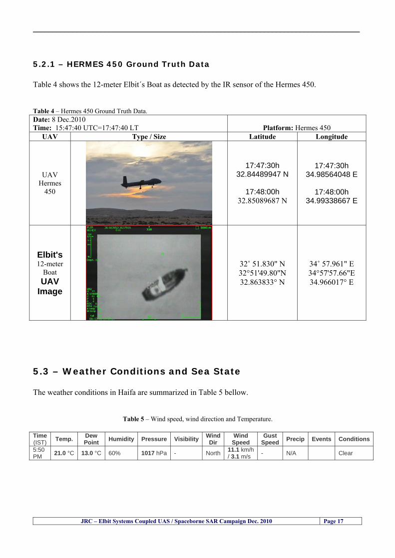
__________________________________________________________________________________
JRC ndash Elbit Systems Coupled UAS Spaceborne SAR Campaign Dec 2010 Page 17
521 ndash HERMES 450 Ground Truth Data Table 4 shows the 12-meter Elbitacutes Boat as detected by the IR sensor of the Hermes 450 Table 4 ndash Hermes 450 Ground Truth Data Date 8 Dec2010 Time 154740 UTC=174740 LT
Platform Hermes 450
UAV Type Size Latitude Longitude
UAV Hermes
450
174730h 3284489947 N
174800h
3285089687 N
174730h 3498564048 E
174800h
3499338667 E
Elbits 12-meter
Boat UAV
Image
32˚ 51830 N 32deg514980N 32863833deg N
34˚ 57961 E 34deg575766E 34966017deg E
53 ndash Weather Conditions and Sea State The weather conditions in Haifa are summarized in Table 5 bellow
Table 5 ndash Wind speed wind direction and Temperature Time (IST) Temp Dew
Point Humidity Pressure Visibility Wind Dir
Wind Speed
Gust Speed Precip Events Conditions
550 PM 210 degC 130 degC 60 1017 hPa - North 111 kmh
31 ms - NA Clear
__________________________________________________________________________________
JRC ndash Elbit Systems Coupled UAS Spaceborne SAR Campaign Dec 2010 Page 18
Figure 10 gives the weather data (Temperature Barometric Pressure Wind Speed and Wind Direction) for Haifa Israel on 8 Dec 2010
Figure 10 ndash Weather data (Temperature Barometric Pressure Wind Speed and Wind Direction) for Haifa Israel on 8 Dec 2010
__________________________________________________________________________________
JRC ndash Elbit Systems Coupled UAS Spaceborne SAR Campaign Dec 2010 Page 19
54 ndash Verification of the Results This section briefly describes the verification of the targets detected in the spaceborne SAR image and in the Hermes 450 UAV using the ground truth data collected during the experiment
541 ndash Overview of the UAV Trajectory and the SAR Imagery Footprint Figure 11 gives an overview of the UAV trajectory the footprint of the SAR imagery and the area of the experiment near the port of Haifa The UAV trajectory is depicted in blue The large red rectangle is the footprint of the TerraSAR-X Stripmap The smaller red rectangle is the footprint of the Radarsat-2 Spotlight image
Figure 11 ndash Google Earth UAV trajectory during the experiment and footprinst of the SAR imagery ordered for the experiment Figure 12 is a zoom in of the previous image which allows a more detailed view of the UAV trajectory and of the port of Haifa Figure 13 is a zoom in of figure 12 It shows in more detail the UAV trajectory during the entire experiment and the port of Haifa in Israel
__________________________________________________________________________________
Figure 12 ndash Zoom in of the previous figure showing a more detailed view of the UAV trajectory and of the port of Haifa in Israel
Figure 13 ndash Zoom in of the previous figure showing a even more detailed view of the UAV trajectory and of the port of Haifa in Israel
JRC ndash Elbit Systems Coupled UAS Spaceborne SAR Campaign Dec 2010 Page 20
__________________________________________________________________________________
JRC ndash Elbit Systems Coupled UAS Spaceborne SAR Campaign Dec 2010 Page 21
542 ndash Targets Detected in the Radarsat-2 Spotlight Image Figure 14 illustrates the position of the Elbitrsquos boat used as target in the experiment at the approximate time of the SAR Satellite pass by 1547 UTC (1747 LT) The small photo of the boat shows the approximate position of the boat The two small planes show the positions of the UAV immediately before and after the SAR Satellite pass
Figure 14 ndash Google Earth positions of the elbitrsquos boat and the UAV (Hermes450) at the approximate time of the SAR Satellite overpass by 174740 UTC Figure 15 shows the corresponding SAR image (Radarsat-2 Spotlight) acquired during the experiment Pins 1 and 2 represent the positions of the UAV before and after the SAR satellite overpass Pin 3 illustrates the position of the Elbitacutes boat deployed at the time of the satellite overpass At this scale the SAR signature of the boat is not distinguishable from the sea clutter background However zooming in the SAR image the SAR signature can clearly be seen as illustrated in figure 12 The SAR image in figure 12 also shows several SAR signatures of large ships in the area at the time of the satellite overpass
__________________________________________________________________________________
JRC ndash Elbit Systems Coupled UAS Spaceborne SAR Campaign Dec 2010 Page 22
Elbit`s Boat
Figure 15 ndash On the background the SAR image with the two UAV positions before and after the satellite overpass (Pin1 and Pin2) and the Elbitacutes Boat position (Pin3) The small window over the SAR image shows a zoom in of the SAR image where the SAR signature of the Elbitacutes Boat can clearly be seen The top right are of the SAR image also shows SAR signatures of several large ships in the area at the time of the SAR satellite overpass Figure 16 shows the corresponding SAR image (Radarsat-2 Spotlight) acquired during the experiment and the UAV IR images of some of the targets Pins 1 and 2 represent the positions of the UAV before and after the SAR satellite overpass Pin 3 illustrates the position of the Elbitacutes boat deployed at the time of the satellite overpass At this scale the SAR signature of the boat is not distinguishable from the sea clutter background However zooming in the SAR image the SAR signature can clearly be seen as illustrated in figure 13 On the top left the UAV IR image of the Elbitrsquos Boat The SAR image in figure 13 also shows several SAR signatures of large ships in the area at the time of the satellite overpass On the centre left the UAV IR image of a large ship On the centre right the UAV IR image of a large ship On the bottom right the UAV IR image of a large ship All the UAV images were acquired at night in complete darkness from altitudes in the order of 5500 meters Nonetheless the quality and detail of the UAV images allows classification of the targets and in some cases the identification As it can be seen the potential of UAV for maritime surveillance is very promising During the experiment the UAV detected all the boats and ships in the area and tracked some of the boatsships to test the tracking capability The capability of detection and tracking targets is a critical capability for maritime surveillance
__________________________________________________________________________________
JRC ndash Elbit Systems Coupled UAS Spaceborne SAR Campaign Dec 2010 Page 23
Elbitacutes Boat
Elbit`s Boat
Figure 16 ndash Zoom-in of figure 15 with the UAV images of some targets On the top left the UAV IR image of the Elbitrsquos Boat On the centre left the UAV IR image of a large ship On the centre right the UAV IR image of a large ship On the bottom right the UAV IR image of a large ship Figure 17 shows a comparison of the SAR and UAV images with an optical photo taken in Haifa Israel a couple of hours before the SAR satellites overpass Most of the large ships were detected in the SAR image and some of these ships can be identified in the optical photo Some of the ships in the photo left the area before the SAR satellites overpass
__________________________________________________________________________________
JRC ndash Elbit Systems Coupled UAS Spaceborne SAR Campaign Dec 2010 Page 24
Figure 17 ndash Photo taken in Haifa Israel a couple of hours before the SAR satellites overpass This phot shows the large ships moored in the area Most of these large ships were detected in the Radarsat-2 image As expected their positions and orientations were slightly different at the time of the satellite overpass
Elbitacutes Boat
Elbit`s Boat
__________________________________________________________________________________
JRC ndash Elbit Systems Coupled UAS Spaceborne SAR Campaign Dec 2010 Page 25
Figure 18 ndash Photo taken in Haifa Israel a couple of hours before the SAR satellites overpass This phot shows the large ships moored in the area Most of these large ships were detected in the Radarsat-2 image As expected their positions and orientations were slightly different at the time of the satellite overpass Figure 18 illustrates the SAR image and the corresponding google earth image of a small pier in the port of Haifa In the SAR image due to several artefacts it is not possible to detect the 7 small boats moored to the small pier The UAR IR image of the same area clearly shows the 7 small boats with impressive detail taking into account that the image was acquired from an altitude of about 5500 meters A zoom in of the same UAV IR image is shown in figure 19 As it can be seen although the image was acquired from an altitude of about 5500 meters the 7 small boats can be clearly seen with enough detail to allow classification of the type of boat A UAV flight at lower altitude would probably giver a lot more detail and eventually allow the identification of the small boats
__________________________________________________________________________________
JRC ndash Elbit Systems Coupled UAS Spaceborne SAR Campaign Dec 2010 Page 26
Figure 19 ndash UAV IR image of a small pier in the port of Haifa Israel where 7 small boats can be seen with enough detail to allow classification This image was acquired from an altitude of about 5500 meters in the dark
__________________________________________________________________________________
55 ndash Quantitative Analysis of the Spaceborne SAR Image In order to allow a quantitative analysis of the data the spaceborne SAR image was calibrated using ESArsquos NEST software package version 4B The input was the SAR image acquired and the output was the Radiometric Calibration (Sigma Naught (σdeg)) expressed in terms of intensity and in decibel (dB) the Radar Brightness (βdeg) and the Radiometric Normalisation (gamma naught (γdeg))
551 ndash Radarsat-2-Spotlight 08Dec2010 (154740 UTC) Haifa Israel Figure 20 illustrates the Intensity band of a subset of the Radarsat-2Spotlgiht image (08Dec2010)
Figure 20 ndash Radarsat-2 Spotlgiht image (08Dec2010) ndash Sigma Naught (Intensity) band
JRC ndash Elbit Systems Coupled UAS Spaceborne SAR Campaign Dec 2010 Page 27
__________________________________________________________________________________
Figure 21 illustrates the Sigma Naught Coefficient of the Radarsat-2 Spotlgiht image (08Dec2010) expressed in terms of intensity and decibel (dB)
Figure 21 ndash Radarsat-2 Spotlgiht image (08Dec2010) - On the left the Sigma Naught (σdeg) (intensity) and on the right the Sigma Naught (σdeg) (dB)
ormalisation amma Naught (γdeg)) of the Radarsat-2 Spotlgiht image (08Dec2010) expressed in dB
-2 Spotlgiht image (08Dec2010) - On the left the Beta Naught (βdeg) and on the right the Gamma Naught (γdeg) (dB)
Figure 22 illustrates the Radar Brightness (Beta Naught (βdeg)) and the radiometric n(G
Figure 22 ndash Radarsat
JRC ndash Elbit Systems Coupled UAS Spaceborne SAR Campaign Dec 2010 Page 28
__________________________________________________________________________________ Figure 23 shows the Sigma Naught (σdeg) in dB after some colour manipulation and the histogram of the Sigma Naught (σdeg) image
Figure 23 ndash Radarsat-2 Spotlgiht image (08Dec2010) - On the top left the Sigma Naught (σdeg) after colour manipulation to enhance the targets and on the top right the corresponding histogram On the bottom we can see the histogram of the image
Table 6 gives the statistics of the Sigma Naught (σdeg) Radarsat-2 Spotlgiht image (08Dec2010) The Sigma Naught (σdeg) range from -72897 dB up to 23465 dB The Mean value is -16855 dB the Median is -16594 dB and the standard deviation is 7077 dB
JRC ndash Elbit Systems Coupled UAS Spaceborne SAR Campaign Dec 2010 Page 29
__________________________________________________________________________________
JRC ndash Elbit Systems Coupled UAS Spaceborne SAR Campaign Dec 2010 Page 30
Table 6 ndash Statistics of the Radarsat-2 Spotlgiht image (08Dec2010) (154740 UTC)
Statistics Values Unit Only ROI-Mask pixels considered Number of pixels total Number of considered pixels Ratio of considered pixels
No 322394283 322394283
1000
Minimum Maximum
-728974609375 234655818939209
intensity_db intensity_db
Mean Median Std-Dev Coefficient of Variation
-16855686580177853 -1659462338617847 707796800831575
07888765273432338
intensity_db intensity_db intensity_db intensity_db
Checking the radar backscattering coefficient of some targets (small boat and some large ships) detected in the Radarsat-2 Spotlight image we get values ranging from -0379 dB up to 23455 dB The analysis of the Sigma Naught values (σdeg) of the targets and the area around the targets shows a significant contrast
56 ndash Summary of the Preliminary Analysis of the Spaceborne SAR Image This experiment involved two spaceborne SAR images namely a TerraSAR-X Stripmap and one Radarsat-2 Spotlight The TerraSAR-X image was not delivered by DLR due to technical problems The Elbitrsquos boat deployed during the experiment was detected in the Radarsat-2 Spotlight image Several other targets including a set of large ships were also detected Table 7 summarises the characteristics of the SAR image acquired and the targets detected
Table 7 ndash List of SAR Satellite Images acquired during the experiment and detected boats ISRAEL (HAIFA)
Date Time Place Satellite Mode Ground Truth Data Detected Boats
08Dec2010 (PM) Haifa - Israel Radarsat-2 Spotlight GPSPhotosMovies 1 small boat deployed + 9 large ships
Table 8 gives the minimum and maximum Sigma Naught (σdeg) of the targets detected in each SAR image
Table 8 ndash Minimum and maximum Sigma Naught (σdeg) of the targets detected in each SAR image
Date Time UTC (LT)Pass Satellite Image Mode Polarisation Sigma Naught (σdeg) Min Max
29Oct2010528UTC(728AM LT) DES Radarsat-2 Spotlight HH --0379 dB 23455 dB The SAR signatures of the boats deployed were very weak Some possible reasons to explain such weak signatures are the sea state the wind speed the incidence angle and the type and materials Another possible reason is the processing at DLR
__________________________________________________________________________________
JRC ndash Elbit Systems Coupled UAS Spaceborne SAR Campaign Dec 2010 Page 31
6 ndash Preliminary Conclusions The analysis of the results of this coupled UASSpaceborne SAR experiment shows a promising potential for the use of UAS for maritime surveillance UAS can be integrated into the airborne building block of maritime surveillance systems to complement the existing assets increase system performance and improve the overall maritime domain awareness The main perceived maritime security and safety threats comprise piracy terrorist and military threats weapons proliferationsmuggling drugs trafficking illegal immigration unlawful use of containers attacks to critical infrastructures and illegal fishing The main maritime security and safety gaps include a lack of technologies with the capability of detecting small targets (eg small boats) a lack of wide area and persistent maritime surveillance a lack of coordination and information sharing limited interoperability a lack of containers security a lack of persistent surveillance of critical infrastructures and early warning systems Unmanned Aircraft Systems (UAS) are an emerging technology with strong potential to mitigate the above mentioned threats by filing in the main maritime security and safety gaps listed earlier For instance the wide range of potential applications of UAS to maritime surveillance includes but is not limited to
bull detection classification and identification of small boats bull persistent maritime surveillance bull use as communications relays bull persistent surveillance of critical infrastructures bull early warning systems bull COMINT and ELINT collection etc
Table 11 illustrates the mapping of maritime securitysafety threats vs gaps and summarises the main potential applications of UAS to maritime surveillance The above mentioned potential applications of UAS to the Maritime Domain will be addressed in turn in more detail next bull Detection classification and identification of small boats ndash The capability of detecting classifying and identifying small targets (eg small boats) is among the key technologies required to improve maritime domain awareness This capability is critical to mitigate piracy illegal immigration drugs trafficking weapons smuggling illegal fishing terrorism and critical infrastructure Unmanned Aircraft Systems (UAS) provide this capability more efficiently and at a lower cost than any other existing technology bull Persistent maritime surveillance ndash With the continuous improvements of UAS technologies such as platforms sensors collision avoidance systems command and control systems telecommunications etc UAS are increasing their autonomy endurance and flexibility These characteristics are very important for persistent maritime surveillance UAS can be launched from land ships aircraft and technologies to launch UAS from submarines are currently under development UAS have distinct advantages over other existing technologies for persistent maritime surveillance in terms of autonomyendurance (the Global Surveyor has an autonomy of 1 week) cost (eg as the autonomy of UAS increases the number of staff required to operate UAS decreases) risk (eg if the UAS crashes the crew is not at risk) flexibility (eg they can be launched from a ship reducing the time to reach potential threats) etc
__________________________________________________________________________________
JRC ndash Elbit Systems Coupled UAS Spaceborne SAR Campaign Dec 2010 Page 32
bull Communications relays ndash UAS are being used as communication relays mainly in military context but have the potential to play a similar role in Civil context in several situations such as to replace satellite communications or as a redundant system over any location on Earth The main advantages of using UAS as communication relays is that airborne communication relays mitigate kinetic and noise jamming threats to satellite communications uplinks by providing an alternative set of links either directly to surface-based terminals or to satellites beyond the range of threats They are less susceptible to noise jamming threats than satellites because an adversary has to detect geolocate and track the airborne asset and operate within line of sight of the receive antenna main beam bull Persistent surveillance of critical infrastructures ndash The security of critical infrastructures such as nuclear power plants refineries ports etc requires persistent surveillance UAS can play an important role in providing persistent surveillance over critical infrastructures and over a wide area around the critical infrastructure Some advantages of UAS over other existing technologies such as ground-based assets (eg video cameras alarm systems manned aircraft etc) comprise the security of the UAS (eg hardly can be damaged or switched off as any ground-based asset) the area covered by a UAS (eg it is larger than the area covered by any ground-based asset) the cost (eg UAS is cheaper than manned aircraft with similar capability) etc bull Early warning systems ndash UAS have the potential to be used as part of an integrated system of systems for early warning A UAS can provide information about a given area at a fraction of the cost of alternative means Formation flying of UAS can cover a wide maritime area It is reasonable to assume that in a foreseeable future with the advent of UAS with increased autonomy the operations cost of UAS will likely decrease making them increasingly more attractive bull COMINT and ELINT collection ndash SIGNal INTelligence (SIGNINT) can be divided into two categories namely COMINT and ELINT COMINT stands for Communication Intelligence and ELINT for Electronic Intelligence Collection of COMINT is passive Exploitation of COMINT requires a human operator which implies COMINT UAS are suitable for COMINT and ELINT collection in different scenarios The relatively reduced amount of data collected and analysed during this experiment and the lessons learned do not allow drawing final conclusions about the feasibility of using Unmanned Aerial Systems (UAS) for maritime surveillance However this experiment allowed hands-on experience with UAS technologies and significantly improved the awareness for its applications to maritime surveillance and related issues involved including its potential the feasibility as well as the limiting and enabling factors These different aspects will now be analysed in turn in the next sections Table 11 illustrates the mapping of the main maritime security threats and gaps as well as the main priorities in terms of the different technologies involved in maritime surveillance For each maritime threat the technologies required to fill in each gap is indicated and its priority is expressed in a range of numbers (1 to 3 1 = Maximum Priority 2 = Medium Priority 3 = Low Priority) and colours (Red = Maximum Priority Orange = Medium Priority Green = Low Priority) The main technologies involved in maritime surveillance are listed on the bottom of figure 4 and are reproduced here for convenience of the reader 1- Reporting Systems 2- Sensors 3- Platforms 4- Communications 5- Data Fusion amp Sharing 6- Intelligence and 7- Databases For example the mitigation of the main threat Piracy requires filling in several maritime security gaps (eg lack of persistent surveillance lack of wide-are maritime surveillance lack of small boat detection lack of Early Warning Systems and lack of Information Sharing with maximum priority (1- Red) and among the required technologies listed are UAS LTAAV GEO-HR etc Concerning the remaining two gaps (Limited Interoperability and Containers Security) they are less relevant to mitigate Piracy hence the priority for Limited Interoperability is 2-Orange and for Containers Security is 3- Green
__________________________________________________________________________________ Table 9 ndash The Main Maritime Security and Safety Threats vs Gaps and the technologies that can be used to mitigate them
Maritime Security Main Threats GapsGapsrarr
darrThreats
Lack o f Risk As sessmentCapab ility
La ck of Persiste nt
Surveilla nce
La ck of Wid e-Area su rve illanc e
La ck of Small Boat De tecti on
Lack o f Earl y Warn ing Sys tems
L ack of In forma tion
Sh arin g
L imi ted In terop era bility
Lac k of Co ntai ners
Se cur ity
bull PiracyUAS LTAVG EO-
HR + UAS LT AVGEO-
HR + SAR GEO-HR
+ UAS USV LTAV
+ UAS LTAV
+ Coord in ationamp Sharing +
Inter opera bilityOptimisation +
1 2 3 5 6 7 1 2 3 5 6 7 1 2 3 5 6 1 2 3 123456 4567 1234567 1234567
bull Terro rismUAS LTAVG EO-
HR + UAS L TAV GEO-HR +
SAR AISGEO-HR +
UAS USV LTAV+
Intelligence+
Inte lligen ce+
Inter opera bilityOptimisation +
Intelligence+
1 2 3 5 6 7 1 2 3 5 6 1 2 3 5 6 1 2 3 123456 4567 1234567 1234567
bull Wea pon s ofM ass Dest ru ctio n Smugg ling
UAS LTAVG EO-HR +
UAS LT AVGEO-HR +
SAR AIS+
UAS USV LTAV+
Intelligence+
Inte lligen ce+
Intelligence+
Intelligence+
1 2 3 5 6 7 1 2 3 5 6 1 2 3 5 6 1 2 3 123456 4567 1234567 1234567
bull Drug sTraffic king
UAS LTAVG EO-HR +
UAS LT AVGEO-HR +
SAR AIS+
UAS USV LTAV+
Intelligence+
Inte lligen ce+
Intelligence+
Intelligence+
1 2 3 5 6 7 1 2 3 5 6 1 2 3 5 6 1 2 3 123456 4567 1234567 1234567
bull Illega lImmigratio n
UAS LTAVG EO-HR +
UAS LT AVGEO-HR +
SAR AIS+
UAS USV LTAV+
Intelligence+
Inte lligen ce+
Intelligence+
Intelligence+
1 2 3 5 6 7 1 2 3 5 6 1 2 3 5 6 1 2 3 123456 4567 1234567 1234567
bull Critic alI nfrastruc tureSecu rit y
UAS LTAVG EO-HR +
UAS LT AVGEO-HR +
SAR AIS+
UAS USV LTAV+ + Inte lligen ce
+ Intelligence
+ Intelligence
+
1 2 3 5 6 7 1 2 3 6 1 2 3 5 6 1 2 3 123456 4567 1234567 1234567
bull Illega lFish ing
UAS LTAVG EO-HR +
AI S+SAR UASLTAV +
SAR AIS GEO-HR+
UAS USV LTAV+
Intelligence+
Inte lligen ce+
Intelligence+
1 2 3 5 6 7 1 2 3 5 7 1 2 3 5 6 1 2 3 123456 4567 1234567
bull Un lawf ul Use of Co nta iners
(Secur ity)
UAS LTAVG EO-HR +
GPS Tr acking+
Intelligence+
Inte lligen ce+
GPS Int rusion Det ection Se al
1 2 3 5 6 7 4 6 7 1 2 3 5 6 1 2 3 123456 4567 1234567 1234567
(-) Priority (+) Not Rel evant
SURVEILLANCETECHNOLOGIES
1- Reporti ng Systems
2 -Sensors 3 -P latforms 4 - Communications 5- Data Fusionamp Sharing
6 -I ntelli gence 7 -Databases
JRC ndash Elbit Systems Coupled UAS Spaceborne SAR Campaign Dec 2010 Page 33
__________________________________________________________________________________
JRC ndash Elbit Systems Coupled UAS Spaceborne SAR Campaign Dec 2010 Page 34
61 ndash Hands-on experience with UAS technologies and its applications to maritime surveillance This coupled UASSpaceborne SAR campaign was a unique opportunity to acquire further handsndashon experience with UAS technologies and learn about the main issues related to its applications to maritime surveillance From the planning phase up to the execution of the UAS flight and landing there are several factors that need to be carefully analysed and taken into account A summary of the main issues identified in this experiment is given next 1- Selection of the Experiment Area Authorisation to Fly ndash For the time being UAS can only be flown in restricted areas usually under control of national authorities often the military This is due to the risks that a UAS can pose to human life and property In the present case an area under the authority of the Israeli Civil Aviation Authority was selected The authorisation to fly was not easy to obtain because the selected area is under the authority of the Civil Aviation Authority Figure 24 indicates the area of the experiment in Haifa Israel 2- UAS Communications Issues ndash The Hermes 450 was flown in Line-of-Sight (LOS) since it was close to the coast For BLOS (Beyond Line-of-Sight) operation satellite communications are required 3- Synthetic Aperture Radar (SAR) ndash The specific model Hermes 450W used in the experiment had no SAR sensor installed However a SAR sensor can be installed A SAR sensor is important for maritime surveillance since it allows 247 operations regardless of the weather conditions 4- Automatic Identification System (AIS) Receiver ndash The Hermes 450 used in this experiment was not equipped with an AIS receiver For maritime surveillance operations an AIS receiver is a very important tool since it allows the automatic identification of most ships allowing the UAS to concentrate on non-identified ships
__________________________________________________________________________________
Figure 24 ndash The area of the experiment is indicated by the GPS Trajectory of the UAV
62 ndash Potential of UAS for Maritime Surveillance UAS technologies are relatively recent and involve a wide range of fields spanning from aeronautics and sensors technologies to satellite communications and other engineering disciplines Innovations in each of the fields involved are emerging by the day UAS still have a long way to go before they become mature and their use fully operational For the time being UAS are mainly used for military applications However a large number of non-military UAS applications have been identified by stakeholders and there are several studies and demonstration flights foreseen for the near future Maritime surveillance is one of the most challenging and promising fields of application of UAS The challenges are due to the very demanding conditions under which the UAS must operate over sea and the requirements for safe operation
JRC ndash Elbit Systems Coupled UAS Spaceborne SAR Campaign Dec 2010 Page 35
__________________________________________________________________________________
JRC ndash Elbit Systems Coupled UAS Spaceborne SAR Campaign Dec 2010 Page 36
The present UAS experiment has unveiled some of the potential of UAS for maritime surveillance The UAS tests performed during this experiment include
1 ndash Detection of a Small rubber Boat and a Fishing Ship 2 ndash Tracking of a Small Boat and a Fishing Ship 3 ndash Classification of a Small Boat and a Fishing Ship 4 ndash Identification of a Small Boat and a Fishing Ship 5 ndash Detection and Tracking of People on the Beach
Despite the operational requirement that prevented the UAS from flying bellow 3km the experiment has confirmed the capability of UAS for small boat detection tracking and classification as well as the capability for people detection and tracking Concerning the identification of the targets the characteristics of the images acquired during this mission suggest that flying at lower altitudes the UAS images would allow the identification of the targets The UAS images can be seen from Figure 15 to 20
621 ndash Advantages of UAS for maritime Surveillance Some of the advantages of using UAS for maritime surveillance have been described in the literature and are summarized bellow
1- One potential benefit of UAS is that they could fill in a gap in current maritime surveillance by improving coverage
2- The range of UAS is a significant asset when compared to border agents on patrol or stationary surveillance equipment
3- Eletro-Optical InfraRed (EOIR) sensors (cameras) can identify small size objects from very high altitudes (high resolution)
4- UAS can provide precise and near-real-time imagery to a ground control operator who would then disseminate that information so that informed decisions regarding the deployment of border patrol agents can be made quickly
5- Long endurance UAS used along the border can fly for more than 30 hours up to several days without having to refuel compared with manned helicopterrsquos average flight time of just over 2 hours
6- The ability of UAS to loiter for prolonged periods of time has important operational advantages over manned aircraft
7- The longer flight times of UAS means that sustained coverage over a previously exposed area may improve maritime security
8- The range of UAVs is a significant asset when compared to border agents on patrol or stationary surveillance equipment Nevertheless the extended range and endurance of UAVs may lessen the burdens on human resources at the borders
9- UAS accidents do not risk the lives of pilots as do the helicopters and aircraft currently used by Coast Guards for border patrolling
__________________________________________________________________________________
JRC ndash Elbit Systems Coupled UAS Spaceborne SAR Campaign Dec 2010 Page 37
622 ndash Possible Drawbacks of using UAS for maritime Surveillance UAS also have disadvantages some of them are briefly described next
1- There have been concerns regarding the high accident rate of UAS which can be multiple times higher than that of manned aircraft Because UAS technology is still evolving there is less redundancy built into the operating system of UAS than of manned aircraft and until redundant systems are perfected mishap rates are expected to remain high
2- If control systems fail in a manned aircraft a well-trained pilot is better positioned to find the source of the problem because of hisher physical proximity If a UAS encountered a similar system failure or if a UAS landing was attempted during difficult weather conditions the ground control pilot would be at a disadvantage because he or she is removed from the event Unlike a manned pilot the remote pilot would not be able to assess important sensory information such as wind speed
3- Inclement weather conditions can also impinge on a UAS surveillance capability especially UAS equipped with only an EO camera and Forward Looking Infrared Radar (FLIR) because cloudy conditions and high humidity climates can distort the imagery produced by EO and FLIR equipment The effects of extreme climatic or atmospheric conditions on sensors reportedly can be mitigated with the outfit of one synthetic aperture radar (SAR) system and a moving target indicator (MTI) radar However adding SAR and MTI to a UAS platform would increase the costs associated with using UAS
4- Depending on the type of UAS the costs of operating a UAS can be higher than the costs of operating a manned aircraft This is because some types of UAS require a significant amount of logistical support and specialized operator and maintenance training Operating one UAS may require a crew of up to 20 support personnel The high comparative costs of operating some sophisticated types of UAS may be offset somewhat by their comparatively lower unit costs
63 ndash Main Limiting Factors Preventing the Use of UAS Several pre-requisites must be satisfied to render the UAS a viable cost-effective and regulated alternative to existing resources Major civil and commercial market barriers include
Single European Sky Sense and Avoid technologies Command and Control Technologies Reliability Communications (Bandwidth LOS BLOS)
Lack of airspace regulation that covers all types of UAV systems (encompassing lsquosense and avoidrsquo airspace integration and airworthiness issues)
Affordability - price and customization issues (eg commercial off-the-shelf open modular architecture) Lack of efforts to establish joint customer requirements (although this is gradually changing) Liability for civil operation Capacity for payload flexibility Lack of sufficient secure non-military frequencies for civil operation Perceived reliability (eg vehicle attrition rate vs manned aircraft) Operator training issues Recognitioncustomer perception of the UAV market Technology developments for multi-mission capability
__________________________________________________________________________________
64 ndash UAS Key Enabling Technologies Figure 25 illustrates the components of a typical UAV System showing some of the capabilities needed and the enabling technologies required for performing a given mission Any UAV mission involves many capabilities and technologies Due to the depicted system complexity the main key players such as the US Department of Defense (DoD) and other agencies have started to use the term Unmanned Aerial System (UAS) in place of UAV
Figure 25 ndash Unmanned Aerial Vehicle System Enabled by Autonomous Mission Management Reliable Flight Systems Navigation Accurate Systems Terrain Avoidance Power and Propulsion Some UAS key enabling technologies are listed below
Autonomous Mission Management Collision Avoidance Intelligent System Health Monitoring
Reliable Flight Systems Sophisticated Contingency Management Intelligent Data Handling and Processing Over-the-Horizon Communication Network-Centric Communication Open Architecture Power and Propulsion Navigation Accurate System Technology Enhanced Structures
JRC ndash Elbit Systems Coupled UAS Spaceborne SAR Campaign Dec 2010 Page 38
__________________________________________________________________________________
JRC ndash Elbit Systems Coupled UAS Spaceborne SAR Campaign Dec 2010 Page 39
Table 12 gives a more detailed description of other critical technologies for emerging autonomous UAV systems both civil and military Most of the technologies mentioned in Table 12 apply both to civil and military UAV systems Table 10 ndash Key Enabling Technologies (from SG75 study on autonomous systems)
Critical Technologies Decision Making Software
bull Fuzzy-based decision making bull Knowledge-based system bull Case-based reasoning bull Self-learning techniques bull Decision tree evaluation bull ReasoningInferring bull Probabilisticstochastic reasoning
Prediction Algorithms bull Predictive pathintent algorithms bull Short reaction algorithm bull Effectiveness evaluation
Status Assessment Software bull Internal status analysis bull Self-orientation
Situation Analysis Software bull Situation analysis bull Environmental analysis bull External status analysis
Modelling Software bull Air vehicle modelling algorithms bull Sensor modelling algorithms bull Scenario generation bull Threat system modeling bull Attack simulation bull Mission success optimisation model bull Simulation
Sensor Processing Software bull Sensor fusion bull Area of interest identification bull Automatic target recognition
Adaptive and Self-learning Systems bull Failure self-compensation
Attack Planning Software bull Attack plans and tactical alternatives bull Plan change impact identification
Weapon Engagement Procedure Software bull Weapon engagement algorithms
Mission Plan Update Software bull Route planning system bull Payload plan management system bull Mission Success Optimisation model
Path Optimisation Software bull Optimal trajectory planning bull Path Optimisation System
Targeting Software bull Target tracking bull Target prioritisation
Platform Technologies bull Obstacle detection and avoidance (airborne) bull Obstacle detection and avoidance (ground) bull Improved autopilot bull Speech recognition
Figure 26 summarises system element designs needed to transition from current to next-generation autonomous UAV systems for civilian and military UAS
__________________________________________________________________________________
Figure 26 ndash System Element Designs Needed to Transition from Current to Next-Generation Autonomous UAV Systems These new paradigms are a combination of system attributes and technological capabilities For instance the data fusion secure anti-jam and coordinated multi-vehicle control require technological development as well as specific system development to bring full maturity to unmanned systems Finally very small Micro UAVs (MAVs) and relatively large sophisticated UCAV systems are examples of the range of UAVs that are applying the new platforms payloads onboard processing communications etc to create next generation automated UAVs It is with these new platforms payloads etc that both UCAVs and MAV will be able to address similar operational challenges including
Mixed operation with other assets bull Deconfliction collision avoidance C4I integration
Operation over populated areas bull Safety issues Need to reduce reliance on communications bull UCAV ndash countermeasures bull MAV ndash limited size and power bull Limited line of sight environment Need a fully integrated system bull MAV propulsionpower generation still critical bull Operator machine interface critical bull All weather operations bull Survivability
JRC ndash Elbit Systems Coupled UAS Spaceborne SAR Campaign Dec 2010 Page 40
__________________________________________________________________________________
JRC ndash Elbit Systems Coupled UAS Spaceborne SAR Campaign Dec 2010 Page 41
65 ndash Mission Readiness
651 ndash Mission Readiness Summary This section summarises civil UAV mission readiness The purpose of Mission Readiness is to assess the readiness status of the different technologies involved in UAS In the present case this civil UAV mission readiness based on technology maturation forecasts that meet or exceed the desired or required capabilities identified by the user community Figure 27 summarises the mission readiness time forecasts for the different technologies The technologies annotated with an asterisk () are shown within the figure with maturation forecasts based on development targets expressed in the US Department of Defencesrsquo UAV Roadmap document The purpose of the chart is to be able to identify when the capability to fly a particular mission can be expected as a function of time The left-most end is the least probable and the right end the most probable timeframe
Figure 27 ndash Technology Maturation Summaries in Terms of Mission-Derived Capabilities
__________________________________________________________________________________
JRC ndash Elbit Systems Coupled UAS Spaceborne SAR Campaign Dec 2010 Page 42
66 ndash Small Boat Detection in SAR Satellite Imagery The use of spaceborne SAR imagery for small boat detection requires additional small boat detection experiments under different conditions using different methods It is not possible to draw final conclusions based on a limited number of small boat detection experiments which are not representative of the multiple possible scenarios
67 ndash Limitations of current State-of-the-Art SAR Satellite technology The main limitations of current State-of-the-Art spaceborne SAR imagery for maritime surveillance in particular aimed at small boat detection are 1 - SAR satellites repeat cycles do not allow the coverage of the same area at the required time intervals Constellations of SAR satellites could be a solution 2 - The conflict between resolution and image swath High resolution is required to detect small boats However the high resolution images have small swaths Maritime surveillance with high resolution images would require a large number of images to cover wide maritime areas which is very expensive and for the time being technically not feasible Intelligence data can play an important role by indicating an approximate position of suspicious non cooperative targets therefore reducing the surveillance area which can then be imaged using high resolution images 3- Spaceborne high resolution SAR imagery acquisition times are long enough to allow significant motion of the target during the acquisition time degrading the quality of the image Further research efforts are needed to develop new sensors and platforms As far as sensors are concerned shorter integration times are needed to prevent the blurring effect caused by the motion of the targets Regarding the platforms more platforms are needed to allow lower repeat cycles and improved coverage
__________________________________________________________________________________
JRC ndash Elbit Systems Coupled UAS Spaceborne SAR Campaign Dec 2010 Page 43
7 ndash Plans for Future Work The controlled experiments carried out by the EC-JRC together with Elbit Systems in Haifa-Israel comprised the deployment of a UAS (Hermes-450) and one small 12-meter boat A Radarsat-2 Spotlight image was acquired and several images collected by the Hermes-450 The experiment unveiled the potential of UAS for maritime surveillance in particular for detection tracking classification and possible identification of small targets The UAS was able to detect track and classify small targets such as small boats For low UAS altitude flights identification may be possible in some cases The small 12-meter boat was detected in the spaceborne SAR image The small boat detection trials carried out by the JRC were very successful since most small boats deployed during the experiments were detected in different sea states wind speeds and geographical locations The several small boat detection campaigns conducted by the EC-JRC seem to suggest that the probability of detection of small boats in spaceborne SAR images strongly depends on factors such as the sea state the wind speed the type of boat (shape and materials) the weather conditions among other factors The results of the experiments conducted thus far are not enough to draw final conclusions about the feasibility of using spaceborne SAR imagery for small boat detection However the experiments have an overall positive outcome because they indicate that under suitable sea state and wind speed conditions it is possible to detect small boats using spaceborne SAR The estimation of the probability of detection of small boats in spaceborne SAR images requires a large number of experiments under different circumstances (eg sea state wind speed characteristics of the targets image type and mode etc) Future plans include additional UAS experiments to asses its potential for maritime surveillance
Acknowledgements ndash The authors would like to express their gratitude to Elbit Systems for their cooperation logistical support and assets deployed without which the present coupled UASSAR Satellite Small Boat Detection Campaign would have not been possible
__________________________________________________________________________________
JRC ndash Elbit Systems Coupled UAS Spaceborne SAR Campaign Dec 2010 Page 44
REFERENCES [1] Elbit Systems ldquoUAV Elbit Systems Proposal for Unmanned Aerial Vehicle (UAV) flight to
collect Ground Truth data during a Maritime Surveillance Campaign and demonstrate UAV capabilities for Maritime Surveillancerdquo 2010
[2] ndash Cheryl Yuhas Suborbital Science Program Manager NASA Science Mission Directorate ldquoEarth Observations and the Role of UAVs A Capabilities Assessment Version 11rdquo Civil UAV Assessment Team httpwwwnasagovcentersdrydenresearchcivuavindexhtml August 2006
[3] ndash Document NIAG (SG75) NATO Industrial Advisory Group Study Group 75 Pre-Feasibility Study on UAV Autonomous Operations 2004
[4] ndash United States Department of Defence (DoD) Directive 50001 ldquoThe Defense Acquisition Systemrdquo and DoD Instruction 50002 ldquoOperation of the Defense Acquisition Systemrdquo
[5] ndash Mr James Ramage Mr Massimo Avalle Dr Erik Berglund Dr Luigi Crovella Mr Robert Frampton Dr Uwe Krogmann Mr Christian Ravat Mr Mike Robinson Dr Axel Schulte Dr Scott Wood ldquoRTO-TR-SCI-118 - Automation Technologies and Application Considerations for Highly Integrated Mission Systemsrdquo RTO-TR-SCI-118 AC323(SCI-118)TP204 January 2009
[6] Victor MG Silva Gilles Jurquet Gabriel Marchalot Maria TG Calzado Txema Soroa Juan Sancho Adam Koubek Harm Greidanus and Claudio Savarino ldquoWide Maritime Area Airborne Surveillance (WIMA2S) WP5 Final Reportrdquo WIMAAS WP5 FP7 Project 2008-2011 - ISBN-978-92-79-22801-8 (print) 978-92-79-22802-5 (PDF) ISSN-1018-5593 (print) 1831-9424 (online) EC-JRC Scientific Report JRC 70093 2012
[7] Victor MG Silva and Harm Greidanus ldquoSpaceborne SAR Small Boat Detection Campaign in Portugal and Spainrdquo EUR 25281 EN ISBN 978-92-79-22553-6 ISSN 1831-9424 (online) EC-JRC Scientific Report JRC68160 2012
[8] Goncalves Da Silva V Van Wimersma Greidanus H Hejmanowska B Loudjani P ldquoUAS Applications With Societal Benefits ndash JRCrsquos UAS-Related Activitiesrdquo 2011-2012 UAS Yearbook - UAS Unmanned Aircraft Systems - The Global Perspective 9 (9) 2011 p 127-129 JRC66600
[9] Goncalves Da Silva V Van Wimersma Greidanus H ldquoSmall boat detection using TerraSAR-X and Radarsat2 satellite imageryrdquo 4th TerraSAR-X Science Team Meeting 14 February 2011 DLR Oberpfaffenhofen (Germany) German Aerospace Center (DLR) (Organiser) 2011 JRC63663
[10] V Silva Harm Greidanus ldquoJRC - SAR Satellite Small Boat Detection Campaign - Portoroz ndash Sloveniardquo - ISBN-13 978-92-79-21476-9 ISSN (online) 1831-9424 EC-JRC Scientific Report JRC66835 2011
[11] V Silva Harm Greidanus ldquoJRC - SAR satellite small boat detection campaign - Algarve Portugalrdquo - ISBN-13 978-92-79-21265-9 ISSN (online) 1831-9424 ISSN (print) 1018-5593 EC-JRC Scientific Report JRC66631 2011
[12] ndash Goncalves Da Silva V Van Wimersma Greidanus H ldquoJRC-Frontex Spaceborne SAR Small Boat Detection Campaign ndash Italy amp Spainrdquo - ISBN-13 978-92-79-22213-9 ISSN (online) 1831-9424 EC-JRC Scientific Report JRC67517 2011
[13] - PW Vachon SJ Thomas J Cranton HR Edel and MD Henschel Validation of ship detection by the RADARSAT synthetic aperture radar and the Ocean Monitoring Workstation Canadian Journal of Remote Sensing 26(3)200ndash212 2000
[14] - Crisp D (2004) The state-of-the-art in ship detection in Synthetic Aperture Radar imagery DSTO Information Sciences Laboratory Australia
[15] - Joint Research Centre (JRC) of the European Community mdash IMPAST and DECLIMS web site httpintelligencejrcceceuintmarinefishindexhtm
[16] - McCandless SW Jackson CR (2004) Principles of Synthetic Aperture Radar Synthetic Aperture Radar Marine Users Manual NOAA Washington pp 1-23
[17] - Greidanus H (2008) Satellite Imaging for Maritime Surveillance of the European Seas Remote Sensing of the European Seas 343-358
European Commission
EUR 25346 EN --- Joint Research Centre --- Institute for the Protection and Security of the Citizen
Title JRC --- Elbit Systems Coupled UAS and Spaceborne SAR Campaign in Israel
Authors Victor MG Silva Harm Greidanus
Luxembourg Publications Office of the European Union
2012 --- v+44 pp --- 210 x 297 cm
EUR --- Scientific and Technical Research series --- ISSN 181-9424 (online) ISSN 1018-5593 (print)
ISBN 978-92-79-25020-0
doi10278828527
Abstract The European maritime area is one of Europersquos most important assets with regard to resources security and ultimately
prosperity of the Member States A significant part of Europersquos economy relies directly or indirectly on it It is not just the
shipping or fisheries industries and their related activities It is also shipbuilding and ports marine equipment and offshore
energy maritime and coastal tourism aquaculture submarine telecommunications blue biotech and the protection of the
marine environment The European maritime area faces several risks and threats posed by unlawful activities such as drugs
trafficking smuggling illegal immigration organised crime and terrorism Piracy in international waters also constitutes a threat
to Europe since it can disrupt the maritime transport chain These risks and threats can endanger human lives marine resources
and the environment as well as significantly disrupt the transport chain and global and local security It is anticipated that these
risks and threats will endure in the mid and long run In order to keep Europe as a world leader in the global maritime economy
an effective integratedinteroperable sustainable maritime surveillance system and situational awareness are needed
A significant number of unlawful maritime activities such as illegal immigration drugs trafficking smuggling piracy and
terrorism involve mainly small boats because small boats are faster and more difficult to detect using conventional means
Hence it is very important to find out the feasibility of using Unmanned Aerial Systems (UAS) for small boat detection tracking
classification and identification as well as to study the potential of UAS for maritime surveillance Since 2010 the EC-JRC has
carried out a number of UAS maritime surveillance campaigns to study the potential of UAS for maritime surveillance in
particular for small boat detection This report presents the results and conclusions of the JRC --- Elbit Systems Coupled UAS and
Spaceborne SAR campaign carried out in Dec 2010 in Haifa Israel
As the Commissionrsquos in-house science service the Joint Research Centrersquos mission is to provide EU policies with independent evidence-based scientific and technical support throughout the whole policy cycle Working in close cooperation with policy Directorates-General the JRC addresses key societal challenges while stimulating innovation through developing new standards methods and tools and sharing and transferring its know-how to the Member States and international community Key policy areas include environment and climate change energy and transport agriculture and food security health and consumer protection information society and digital agenda safety and security including nuclear all supported through a cross-cutting and multi-disciplinary approach
LB-NA-25346-EN
-N
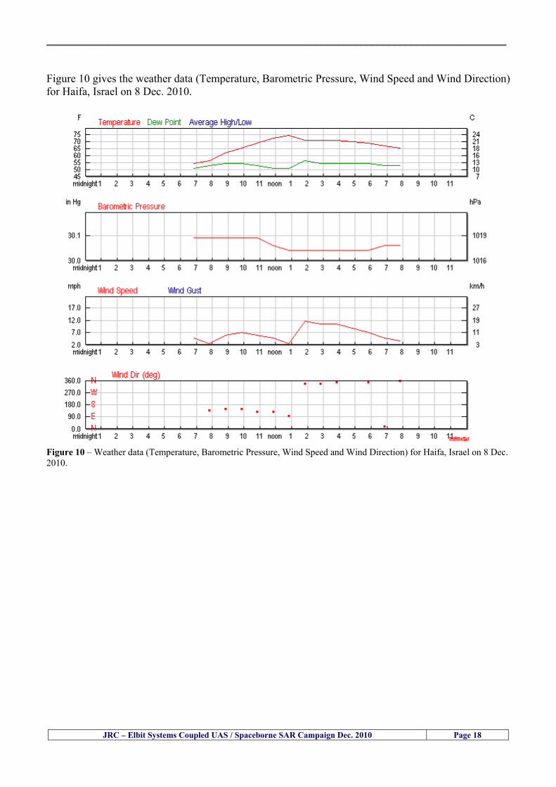
__________________________________________________________________________________
JRC ndash Elbit Systems Coupled UAS Spaceborne SAR Campaign Dec 2010 Page 18
Figure 10 gives the weather data (Temperature Barometric Pressure Wind Speed and Wind Direction) for Haifa Israel on 8 Dec 2010
Figure 10 ndash Weather data (Temperature Barometric Pressure Wind Speed and Wind Direction) for Haifa Israel on 8 Dec 2010
__________________________________________________________________________________
JRC ndash Elbit Systems Coupled UAS Spaceborne SAR Campaign Dec 2010 Page 19
54 ndash Verification of the Results This section briefly describes the verification of the targets detected in the spaceborne SAR image and in the Hermes 450 UAV using the ground truth data collected during the experiment
541 ndash Overview of the UAV Trajectory and the SAR Imagery Footprint Figure 11 gives an overview of the UAV trajectory the footprint of the SAR imagery and the area of the experiment near the port of Haifa The UAV trajectory is depicted in blue The large red rectangle is the footprint of the TerraSAR-X Stripmap The smaller red rectangle is the footprint of the Radarsat-2 Spotlight image
Figure 11 ndash Google Earth UAV trajectory during the experiment and footprinst of the SAR imagery ordered for the experiment Figure 12 is a zoom in of the previous image which allows a more detailed view of the UAV trajectory and of the port of Haifa Figure 13 is a zoom in of figure 12 It shows in more detail the UAV trajectory during the entire experiment and the port of Haifa in Israel
__________________________________________________________________________________
Figure 12 ndash Zoom in of the previous figure showing a more detailed view of the UAV trajectory and of the port of Haifa in Israel
Figure 13 ndash Zoom in of the previous figure showing a even more detailed view of the UAV trajectory and of the port of Haifa in Israel
JRC ndash Elbit Systems Coupled UAS Spaceborne SAR Campaign Dec 2010 Page 20
__________________________________________________________________________________
JRC ndash Elbit Systems Coupled UAS Spaceborne SAR Campaign Dec 2010 Page 21
542 ndash Targets Detected in the Radarsat-2 Spotlight Image Figure 14 illustrates the position of the Elbitrsquos boat used as target in the experiment at the approximate time of the SAR Satellite pass by 1547 UTC (1747 LT) The small photo of the boat shows the approximate position of the boat The two small planes show the positions of the UAV immediately before and after the SAR Satellite pass
Figure 14 ndash Google Earth positions of the elbitrsquos boat and the UAV (Hermes450) at the approximate time of the SAR Satellite overpass by 174740 UTC Figure 15 shows the corresponding SAR image (Radarsat-2 Spotlight) acquired during the experiment Pins 1 and 2 represent the positions of the UAV before and after the SAR satellite overpass Pin 3 illustrates the position of the Elbitacutes boat deployed at the time of the satellite overpass At this scale the SAR signature of the boat is not distinguishable from the sea clutter background However zooming in the SAR image the SAR signature can clearly be seen as illustrated in figure 12 The SAR image in figure 12 also shows several SAR signatures of large ships in the area at the time of the satellite overpass
__________________________________________________________________________________
JRC ndash Elbit Systems Coupled UAS Spaceborne SAR Campaign Dec 2010 Page 22
Elbit`s Boat
Figure 15 ndash On the background the SAR image with the two UAV positions before and after the satellite overpass (Pin1 and Pin2) and the Elbitacutes Boat position (Pin3) The small window over the SAR image shows a zoom in of the SAR image where the SAR signature of the Elbitacutes Boat can clearly be seen The top right are of the SAR image also shows SAR signatures of several large ships in the area at the time of the SAR satellite overpass Figure 16 shows the corresponding SAR image (Radarsat-2 Spotlight) acquired during the experiment and the UAV IR images of some of the targets Pins 1 and 2 represent the positions of the UAV before and after the SAR satellite overpass Pin 3 illustrates the position of the Elbitacutes boat deployed at the time of the satellite overpass At this scale the SAR signature of the boat is not distinguishable from the sea clutter background However zooming in the SAR image the SAR signature can clearly be seen as illustrated in figure 13 On the top left the UAV IR image of the Elbitrsquos Boat The SAR image in figure 13 also shows several SAR signatures of large ships in the area at the time of the satellite overpass On the centre left the UAV IR image of a large ship On the centre right the UAV IR image of a large ship On the bottom right the UAV IR image of a large ship All the UAV images were acquired at night in complete darkness from altitudes in the order of 5500 meters Nonetheless the quality and detail of the UAV images allows classification of the targets and in some cases the identification As it can be seen the potential of UAV for maritime surveillance is very promising During the experiment the UAV detected all the boats and ships in the area and tracked some of the boatsships to test the tracking capability The capability of detection and tracking targets is a critical capability for maritime surveillance
__________________________________________________________________________________
JRC ndash Elbit Systems Coupled UAS Spaceborne SAR Campaign Dec 2010 Page 23
Elbitacutes Boat
Elbit`s Boat
Figure 16 ndash Zoom-in of figure 15 with the UAV images of some targets On the top left the UAV IR image of the Elbitrsquos Boat On the centre left the UAV IR image of a large ship On the centre right the UAV IR image of a large ship On the bottom right the UAV IR image of a large ship Figure 17 shows a comparison of the SAR and UAV images with an optical photo taken in Haifa Israel a couple of hours before the SAR satellites overpass Most of the large ships were detected in the SAR image and some of these ships can be identified in the optical photo Some of the ships in the photo left the area before the SAR satellites overpass
__________________________________________________________________________________
JRC ndash Elbit Systems Coupled UAS Spaceborne SAR Campaign Dec 2010 Page 24
Figure 17 ndash Photo taken in Haifa Israel a couple of hours before the SAR satellites overpass This phot shows the large ships moored in the area Most of these large ships were detected in the Radarsat-2 image As expected their positions and orientations were slightly different at the time of the satellite overpass
Elbitacutes Boat
Elbit`s Boat
__________________________________________________________________________________
JRC ndash Elbit Systems Coupled UAS Spaceborne SAR Campaign Dec 2010 Page 25
Figure 18 ndash Photo taken in Haifa Israel a couple of hours before the SAR satellites overpass This phot shows the large ships moored in the area Most of these large ships were detected in the Radarsat-2 image As expected their positions and orientations were slightly different at the time of the satellite overpass Figure 18 illustrates the SAR image and the corresponding google earth image of a small pier in the port of Haifa In the SAR image due to several artefacts it is not possible to detect the 7 small boats moored to the small pier The UAR IR image of the same area clearly shows the 7 small boats with impressive detail taking into account that the image was acquired from an altitude of about 5500 meters A zoom in of the same UAV IR image is shown in figure 19 As it can be seen although the image was acquired from an altitude of about 5500 meters the 7 small boats can be clearly seen with enough detail to allow classification of the type of boat A UAV flight at lower altitude would probably giver a lot more detail and eventually allow the identification of the small boats
__________________________________________________________________________________
JRC ndash Elbit Systems Coupled UAS Spaceborne SAR Campaign Dec 2010 Page 26
Figure 19 ndash UAV IR image of a small pier in the port of Haifa Israel where 7 small boats can be seen with enough detail to allow classification This image was acquired from an altitude of about 5500 meters in the dark
__________________________________________________________________________________
55 ndash Quantitative Analysis of the Spaceborne SAR Image In order to allow a quantitative analysis of the data the spaceborne SAR image was calibrated using ESArsquos NEST software package version 4B The input was the SAR image acquired and the output was the Radiometric Calibration (Sigma Naught (σdeg)) expressed in terms of intensity and in decibel (dB) the Radar Brightness (βdeg) and the Radiometric Normalisation (gamma naught (γdeg))
551 ndash Radarsat-2-Spotlight 08Dec2010 (154740 UTC) Haifa Israel Figure 20 illustrates the Intensity band of a subset of the Radarsat-2Spotlgiht image (08Dec2010)
Figure 20 ndash Radarsat-2 Spotlgiht image (08Dec2010) ndash Sigma Naught (Intensity) band
JRC ndash Elbit Systems Coupled UAS Spaceborne SAR Campaign Dec 2010 Page 27
__________________________________________________________________________________
Figure 21 illustrates the Sigma Naught Coefficient of the Radarsat-2 Spotlgiht image (08Dec2010) expressed in terms of intensity and decibel (dB)
Figure 21 ndash Radarsat-2 Spotlgiht image (08Dec2010) - On the left the Sigma Naught (σdeg) (intensity) and on the right the Sigma Naught (σdeg) (dB)
ormalisation amma Naught (γdeg)) of the Radarsat-2 Spotlgiht image (08Dec2010) expressed in dB
-2 Spotlgiht image (08Dec2010) - On the left the Beta Naught (βdeg) and on the right the Gamma Naught (γdeg) (dB)
Figure 22 illustrates the Radar Brightness (Beta Naught (βdeg)) and the radiometric n(G
Figure 22 ndash Radarsat
JRC ndash Elbit Systems Coupled UAS Spaceborne SAR Campaign Dec 2010 Page 28
__________________________________________________________________________________ Figure 23 shows the Sigma Naught (σdeg) in dB after some colour manipulation and the histogram of the Sigma Naught (σdeg) image
Figure 23 ndash Radarsat-2 Spotlgiht image (08Dec2010) - On the top left the Sigma Naught (σdeg) after colour manipulation to enhance the targets and on the top right the corresponding histogram On the bottom we can see the histogram of the image
Table 6 gives the statistics of the Sigma Naught (σdeg) Radarsat-2 Spotlgiht image (08Dec2010) The Sigma Naught (σdeg) range from -72897 dB up to 23465 dB The Mean value is -16855 dB the Median is -16594 dB and the standard deviation is 7077 dB
JRC ndash Elbit Systems Coupled UAS Spaceborne SAR Campaign Dec 2010 Page 29
__________________________________________________________________________________
JRC ndash Elbit Systems Coupled UAS Spaceborne SAR Campaign Dec 2010 Page 30
Table 6 ndash Statistics of the Radarsat-2 Spotlgiht image (08Dec2010) (154740 UTC)
Statistics Values Unit Only ROI-Mask pixels considered Number of pixels total Number of considered pixels Ratio of considered pixels
No 322394283 322394283
1000
Minimum Maximum
-728974609375 234655818939209
intensity_db intensity_db
Mean Median Std-Dev Coefficient of Variation
-16855686580177853 -1659462338617847 707796800831575
07888765273432338
intensity_db intensity_db intensity_db intensity_db
Checking the radar backscattering coefficient of some targets (small boat and some large ships) detected in the Radarsat-2 Spotlight image we get values ranging from -0379 dB up to 23455 dB The analysis of the Sigma Naught values (σdeg) of the targets and the area around the targets shows a significant contrast
56 ndash Summary of the Preliminary Analysis of the Spaceborne SAR Image This experiment involved two spaceborne SAR images namely a TerraSAR-X Stripmap and one Radarsat-2 Spotlight The TerraSAR-X image was not delivered by DLR due to technical problems The Elbitrsquos boat deployed during the experiment was detected in the Radarsat-2 Spotlight image Several other targets including a set of large ships were also detected Table 7 summarises the characteristics of the SAR image acquired and the targets detected
Table 7 ndash List of SAR Satellite Images acquired during the experiment and detected boats ISRAEL (HAIFA)
Date Time Place Satellite Mode Ground Truth Data Detected Boats
08Dec2010 (PM) Haifa - Israel Radarsat-2 Spotlight GPSPhotosMovies 1 small boat deployed + 9 large ships
Table 8 gives the minimum and maximum Sigma Naught (σdeg) of the targets detected in each SAR image
Table 8 ndash Minimum and maximum Sigma Naught (σdeg) of the targets detected in each SAR image
Date Time UTC (LT)Pass Satellite Image Mode Polarisation Sigma Naught (σdeg) Min Max
29Oct2010528UTC(728AM LT) DES Radarsat-2 Spotlight HH --0379 dB 23455 dB The SAR signatures of the boats deployed were very weak Some possible reasons to explain such weak signatures are the sea state the wind speed the incidence angle and the type and materials Another possible reason is the processing at DLR
__________________________________________________________________________________
JRC ndash Elbit Systems Coupled UAS Spaceborne SAR Campaign Dec 2010 Page 31
6 ndash Preliminary Conclusions The analysis of the results of this coupled UASSpaceborne SAR experiment shows a promising potential for the use of UAS for maritime surveillance UAS can be integrated into the airborne building block of maritime surveillance systems to complement the existing assets increase system performance and improve the overall maritime domain awareness The main perceived maritime security and safety threats comprise piracy terrorist and military threats weapons proliferationsmuggling drugs trafficking illegal immigration unlawful use of containers attacks to critical infrastructures and illegal fishing The main maritime security and safety gaps include a lack of technologies with the capability of detecting small targets (eg small boats) a lack of wide area and persistent maritime surveillance a lack of coordination and information sharing limited interoperability a lack of containers security a lack of persistent surveillance of critical infrastructures and early warning systems Unmanned Aircraft Systems (UAS) are an emerging technology with strong potential to mitigate the above mentioned threats by filing in the main maritime security and safety gaps listed earlier For instance the wide range of potential applications of UAS to maritime surveillance includes but is not limited to
bull detection classification and identification of small boats bull persistent maritime surveillance bull use as communications relays bull persistent surveillance of critical infrastructures bull early warning systems bull COMINT and ELINT collection etc
Table 11 illustrates the mapping of maritime securitysafety threats vs gaps and summarises the main potential applications of UAS to maritime surveillance The above mentioned potential applications of UAS to the Maritime Domain will be addressed in turn in more detail next bull Detection classification and identification of small boats ndash The capability of detecting classifying and identifying small targets (eg small boats) is among the key technologies required to improve maritime domain awareness This capability is critical to mitigate piracy illegal immigration drugs trafficking weapons smuggling illegal fishing terrorism and critical infrastructure Unmanned Aircraft Systems (UAS) provide this capability more efficiently and at a lower cost than any other existing technology bull Persistent maritime surveillance ndash With the continuous improvements of UAS technologies such as platforms sensors collision avoidance systems command and control systems telecommunications etc UAS are increasing their autonomy endurance and flexibility These characteristics are very important for persistent maritime surveillance UAS can be launched from land ships aircraft and technologies to launch UAS from submarines are currently under development UAS have distinct advantages over other existing technologies for persistent maritime surveillance in terms of autonomyendurance (the Global Surveyor has an autonomy of 1 week) cost (eg as the autonomy of UAS increases the number of staff required to operate UAS decreases) risk (eg if the UAS crashes the crew is not at risk) flexibility (eg they can be launched from a ship reducing the time to reach potential threats) etc
__________________________________________________________________________________
JRC ndash Elbit Systems Coupled UAS Spaceborne SAR Campaign Dec 2010 Page 32
bull Communications relays ndash UAS are being used as communication relays mainly in military context but have the potential to play a similar role in Civil context in several situations such as to replace satellite communications or as a redundant system over any location on Earth The main advantages of using UAS as communication relays is that airborne communication relays mitigate kinetic and noise jamming threats to satellite communications uplinks by providing an alternative set of links either directly to surface-based terminals or to satellites beyond the range of threats They are less susceptible to noise jamming threats than satellites because an adversary has to detect geolocate and track the airborne asset and operate within line of sight of the receive antenna main beam bull Persistent surveillance of critical infrastructures ndash The security of critical infrastructures such as nuclear power plants refineries ports etc requires persistent surveillance UAS can play an important role in providing persistent surveillance over critical infrastructures and over a wide area around the critical infrastructure Some advantages of UAS over other existing technologies such as ground-based assets (eg video cameras alarm systems manned aircraft etc) comprise the security of the UAS (eg hardly can be damaged or switched off as any ground-based asset) the area covered by a UAS (eg it is larger than the area covered by any ground-based asset) the cost (eg UAS is cheaper than manned aircraft with similar capability) etc bull Early warning systems ndash UAS have the potential to be used as part of an integrated system of systems for early warning A UAS can provide information about a given area at a fraction of the cost of alternative means Formation flying of UAS can cover a wide maritime area It is reasonable to assume that in a foreseeable future with the advent of UAS with increased autonomy the operations cost of UAS will likely decrease making them increasingly more attractive bull COMINT and ELINT collection ndash SIGNal INTelligence (SIGNINT) can be divided into two categories namely COMINT and ELINT COMINT stands for Communication Intelligence and ELINT for Electronic Intelligence Collection of COMINT is passive Exploitation of COMINT requires a human operator which implies COMINT UAS are suitable for COMINT and ELINT collection in different scenarios The relatively reduced amount of data collected and analysed during this experiment and the lessons learned do not allow drawing final conclusions about the feasibility of using Unmanned Aerial Systems (UAS) for maritime surveillance However this experiment allowed hands-on experience with UAS technologies and significantly improved the awareness for its applications to maritime surveillance and related issues involved including its potential the feasibility as well as the limiting and enabling factors These different aspects will now be analysed in turn in the next sections Table 11 illustrates the mapping of the main maritime security threats and gaps as well as the main priorities in terms of the different technologies involved in maritime surveillance For each maritime threat the technologies required to fill in each gap is indicated and its priority is expressed in a range of numbers (1 to 3 1 = Maximum Priority 2 = Medium Priority 3 = Low Priority) and colours (Red = Maximum Priority Orange = Medium Priority Green = Low Priority) The main technologies involved in maritime surveillance are listed on the bottom of figure 4 and are reproduced here for convenience of the reader 1- Reporting Systems 2- Sensors 3- Platforms 4- Communications 5- Data Fusion amp Sharing 6- Intelligence and 7- Databases For example the mitigation of the main threat Piracy requires filling in several maritime security gaps (eg lack of persistent surveillance lack of wide-are maritime surveillance lack of small boat detection lack of Early Warning Systems and lack of Information Sharing with maximum priority (1- Red) and among the required technologies listed are UAS LTAAV GEO-HR etc Concerning the remaining two gaps (Limited Interoperability and Containers Security) they are less relevant to mitigate Piracy hence the priority for Limited Interoperability is 2-Orange and for Containers Security is 3- Green
__________________________________________________________________________________ Table 9 ndash The Main Maritime Security and Safety Threats vs Gaps and the technologies that can be used to mitigate them
Maritime Security Main Threats GapsGapsrarr
darrThreats
Lack o f Risk As sessmentCapab ility
La ck of Persiste nt
Surveilla nce
La ck of Wid e-Area su rve illanc e
La ck of Small Boat De tecti on
Lack o f Earl y Warn ing Sys tems
L ack of In forma tion
Sh arin g
L imi ted In terop era bility
Lac k of Co ntai ners
Se cur ity
bull PiracyUAS LTAVG EO-
HR + UAS LT AVGEO-
HR + SAR GEO-HR
+ UAS USV LTAV
+ UAS LTAV
+ Coord in ationamp Sharing +
Inter opera bilityOptimisation +
1 2 3 5 6 7 1 2 3 5 6 7 1 2 3 5 6 1 2 3 123456 4567 1234567 1234567
bull Terro rismUAS LTAVG EO-
HR + UAS L TAV GEO-HR +
SAR AISGEO-HR +
UAS USV LTAV+
Intelligence+
Inte lligen ce+
Inter opera bilityOptimisation +
Intelligence+
1 2 3 5 6 7 1 2 3 5 6 1 2 3 5 6 1 2 3 123456 4567 1234567 1234567
bull Wea pon s ofM ass Dest ru ctio n Smugg ling
UAS LTAVG EO-HR +
UAS LT AVGEO-HR +
SAR AIS+
UAS USV LTAV+
Intelligence+
Inte lligen ce+
Intelligence+
Intelligence+
1 2 3 5 6 7 1 2 3 5 6 1 2 3 5 6 1 2 3 123456 4567 1234567 1234567
bull Drug sTraffic king
UAS LTAVG EO-HR +
UAS LT AVGEO-HR +
SAR AIS+
UAS USV LTAV+
Intelligence+
Inte lligen ce+
Intelligence+
Intelligence+
1 2 3 5 6 7 1 2 3 5 6 1 2 3 5 6 1 2 3 123456 4567 1234567 1234567
bull Illega lImmigratio n
UAS LTAVG EO-HR +
UAS LT AVGEO-HR +
SAR AIS+
UAS USV LTAV+
Intelligence+
Inte lligen ce+
Intelligence+
Intelligence+
1 2 3 5 6 7 1 2 3 5 6 1 2 3 5 6 1 2 3 123456 4567 1234567 1234567
bull Critic alI nfrastruc tureSecu rit y
UAS LTAVG EO-HR +
UAS LT AVGEO-HR +
SAR AIS+
UAS USV LTAV+ + Inte lligen ce
+ Intelligence
+ Intelligence
+
1 2 3 5 6 7 1 2 3 6 1 2 3 5 6 1 2 3 123456 4567 1234567 1234567
bull Illega lFish ing
UAS LTAVG EO-HR +
AI S+SAR UASLTAV +
SAR AIS GEO-HR+
UAS USV LTAV+
Intelligence+
Inte lligen ce+
Intelligence+
1 2 3 5 6 7 1 2 3 5 7 1 2 3 5 6 1 2 3 123456 4567 1234567
bull Un lawf ul Use of Co nta iners
(Secur ity)
UAS LTAVG EO-HR +
GPS Tr acking+
Intelligence+
Inte lligen ce+
GPS Int rusion Det ection Se al
1 2 3 5 6 7 4 6 7 1 2 3 5 6 1 2 3 123456 4567 1234567 1234567
(-) Priority (+) Not Rel evant
SURVEILLANCETECHNOLOGIES
1- Reporti ng Systems
2 -Sensors 3 -P latforms 4 - Communications 5- Data Fusionamp Sharing
6 -I ntelli gence 7 -Databases
JRC ndash Elbit Systems Coupled UAS Spaceborne SAR Campaign Dec 2010 Page 33
__________________________________________________________________________________
JRC ndash Elbit Systems Coupled UAS Spaceborne SAR Campaign Dec 2010 Page 34
61 ndash Hands-on experience with UAS technologies and its applications to maritime surveillance This coupled UASSpaceborne SAR campaign was a unique opportunity to acquire further handsndashon experience with UAS technologies and learn about the main issues related to its applications to maritime surveillance From the planning phase up to the execution of the UAS flight and landing there are several factors that need to be carefully analysed and taken into account A summary of the main issues identified in this experiment is given next 1- Selection of the Experiment Area Authorisation to Fly ndash For the time being UAS can only be flown in restricted areas usually under control of national authorities often the military This is due to the risks that a UAS can pose to human life and property In the present case an area under the authority of the Israeli Civil Aviation Authority was selected The authorisation to fly was not easy to obtain because the selected area is under the authority of the Civil Aviation Authority Figure 24 indicates the area of the experiment in Haifa Israel 2- UAS Communications Issues ndash The Hermes 450 was flown in Line-of-Sight (LOS) since it was close to the coast For BLOS (Beyond Line-of-Sight) operation satellite communications are required 3- Synthetic Aperture Radar (SAR) ndash The specific model Hermes 450W used in the experiment had no SAR sensor installed However a SAR sensor can be installed A SAR sensor is important for maritime surveillance since it allows 247 operations regardless of the weather conditions 4- Automatic Identification System (AIS) Receiver ndash The Hermes 450 used in this experiment was not equipped with an AIS receiver For maritime surveillance operations an AIS receiver is a very important tool since it allows the automatic identification of most ships allowing the UAS to concentrate on non-identified ships
__________________________________________________________________________________
Figure 24 ndash The area of the experiment is indicated by the GPS Trajectory of the UAV
62 ndash Potential of UAS for Maritime Surveillance UAS technologies are relatively recent and involve a wide range of fields spanning from aeronautics and sensors technologies to satellite communications and other engineering disciplines Innovations in each of the fields involved are emerging by the day UAS still have a long way to go before they become mature and their use fully operational For the time being UAS are mainly used for military applications However a large number of non-military UAS applications have been identified by stakeholders and there are several studies and demonstration flights foreseen for the near future Maritime surveillance is one of the most challenging and promising fields of application of UAS The challenges are due to the very demanding conditions under which the UAS must operate over sea and the requirements for safe operation
JRC ndash Elbit Systems Coupled UAS Spaceborne SAR Campaign Dec 2010 Page 35
__________________________________________________________________________________
JRC ndash Elbit Systems Coupled UAS Spaceborne SAR Campaign Dec 2010 Page 36
The present UAS experiment has unveiled some of the potential of UAS for maritime surveillance The UAS tests performed during this experiment include
1 ndash Detection of a Small rubber Boat and a Fishing Ship 2 ndash Tracking of a Small Boat and a Fishing Ship 3 ndash Classification of a Small Boat and a Fishing Ship 4 ndash Identification of a Small Boat and a Fishing Ship 5 ndash Detection and Tracking of People on the Beach
Despite the operational requirement that prevented the UAS from flying bellow 3km the experiment has confirmed the capability of UAS for small boat detection tracking and classification as well as the capability for people detection and tracking Concerning the identification of the targets the characteristics of the images acquired during this mission suggest that flying at lower altitudes the UAS images would allow the identification of the targets The UAS images can be seen from Figure 15 to 20
621 ndash Advantages of UAS for maritime Surveillance Some of the advantages of using UAS for maritime surveillance have been described in the literature and are summarized bellow
1- One potential benefit of UAS is that they could fill in a gap in current maritime surveillance by improving coverage
2- The range of UAS is a significant asset when compared to border agents on patrol or stationary surveillance equipment
3- Eletro-Optical InfraRed (EOIR) sensors (cameras) can identify small size objects from very high altitudes (high resolution)
4- UAS can provide precise and near-real-time imagery to a ground control operator who would then disseminate that information so that informed decisions regarding the deployment of border patrol agents can be made quickly
5- Long endurance UAS used along the border can fly for more than 30 hours up to several days without having to refuel compared with manned helicopterrsquos average flight time of just over 2 hours
6- The ability of UAS to loiter for prolonged periods of time has important operational advantages over manned aircraft
7- The longer flight times of UAS means that sustained coverage over a previously exposed area may improve maritime security
8- The range of UAVs is a significant asset when compared to border agents on patrol or stationary surveillance equipment Nevertheless the extended range and endurance of UAVs may lessen the burdens on human resources at the borders
9- UAS accidents do not risk the lives of pilots as do the helicopters and aircraft currently used by Coast Guards for border patrolling
__________________________________________________________________________________
JRC ndash Elbit Systems Coupled UAS Spaceborne SAR Campaign Dec 2010 Page 37
622 ndash Possible Drawbacks of using UAS for maritime Surveillance UAS also have disadvantages some of them are briefly described next
1- There have been concerns regarding the high accident rate of UAS which can be multiple times higher than that of manned aircraft Because UAS technology is still evolving there is less redundancy built into the operating system of UAS than of manned aircraft and until redundant systems are perfected mishap rates are expected to remain high
2- If control systems fail in a manned aircraft a well-trained pilot is better positioned to find the source of the problem because of hisher physical proximity If a UAS encountered a similar system failure or if a UAS landing was attempted during difficult weather conditions the ground control pilot would be at a disadvantage because he or she is removed from the event Unlike a manned pilot the remote pilot would not be able to assess important sensory information such as wind speed
3- Inclement weather conditions can also impinge on a UAS surveillance capability especially UAS equipped with only an EO camera and Forward Looking Infrared Radar (FLIR) because cloudy conditions and high humidity climates can distort the imagery produced by EO and FLIR equipment The effects of extreme climatic or atmospheric conditions on sensors reportedly can be mitigated with the outfit of one synthetic aperture radar (SAR) system and a moving target indicator (MTI) radar However adding SAR and MTI to a UAS platform would increase the costs associated with using UAS
4- Depending on the type of UAS the costs of operating a UAS can be higher than the costs of operating a manned aircraft This is because some types of UAS require a significant amount of logistical support and specialized operator and maintenance training Operating one UAS may require a crew of up to 20 support personnel The high comparative costs of operating some sophisticated types of UAS may be offset somewhat by their comparatively lower unit costs
63 ndash Main Limiting Factors Preventing the Use of UAS Several pre-requisites must be satisfied to render the UAS a viable cost-effective and regulated alternative to existing resources Major civil and commercial market barriers include
Single European Sky Sense and Avoid technologies Command and Control Technologies Reliability Communications (Bandwidth LOS BLOS)
Lack of airspace regulation that covers all types of UAV systems (encompassing lsquosense and avoidrsquo airspace integration and airworthiness issues)
Affordability - price and customization issues (eg commercial off-the-shelf open modular architecture) Lack of efforts to establish joint customer requirements (although this is gradually changing) Liability for civil operation Capacity for payload flexibility Lack of sufficient secure non-military frequencies for civil operation Perceived reliability (eg vehicle attrition rate vs manned aircraft) Operator training issues Recognitioncustomer perception of the UAV market Technology developments for multi-mission capability
__________________________________________________________________________________
64 ndash UAS Key Enabling Technologies Figure 25 illustrates the components of a typical UAV System showing some of the capabilities needed and the enabling technologies required for performing a given mission Any UAV mission involves many capabilities and technologies Due to the depicted system complexity the main key players such as the US Department of Defense (DoD) and other agencies have started to use the term Unmanned Aerial System (UAS) in place of UAV
Figure 25 ndash Unmanned Aerial Vehicle System Enabled by Autonomous Mission Management Reliable Flight Systems Navigation Accurate Systems Terrain Avoidance Power and Propulsion Some UAS key enabling technologies are listed below
Autonomous Mission Management Collision Avoidance Intelligent System Health Monitoring
Reliable Flight Systems Sophisticated Contingency Management Intelligent Data Handling and Processing Over-the-Horizon Communication Network-Centric Communication Open Architecture Power and Propulsion Navigation Accurate System Technology Enhanced Structures
JRC ndash Elbit Systems Coupled UAS Spaceborne SAR Campaign Dec 2010 Page 38
__________________________________________________________________________________
JRC ndash Elbit Systems Coupled UAS Spaceborne SAR Campaign Dec 2010 Page 39
Table 12 gives a more detailed description of other critical technologies for emerging autonomous UAV systems both civil and military Most of the technologies mentioned in Table 12 apply both to civil and military UAV systems Table 10 ndash Key Enabling Technologies (from SG75 study on autonomous systems)
Critical Technologies Decision Making Software
bull Fuzzy-based decision making bull Knowledge-based system bull Case-based reasoning bull Self-learning techniques bull Decision tree evaluation bull ReasoningInferring bull Probabilisticstochastic reasoning
Prediction Algorithms bull Predictive pathintent algorithms bull Short reaction algorithm bull Effectiveness evaluation
Status Assessment Software bull Internal status analysis bull Self-orientation
Situation Analysis Software bull Situation analysis bull Environmental analysis bull External status analysis
Modelling Software bull Air vehicle modelling algorithms bull Sensor modelling algorithms bull Scenario generation bull Threat system modeling bull Attack simulation bull Mission success optimisation model bull Simulation
Sensor Processing Software bull Sensor fusion bull Area of interest identification bull Automatic target recognition
Adaptive and Self-learning Systems bull Failure self-compensation
Attack Planning Software bull Attack plans and tactical alternatives bull Plan change impact identification
Weapon Engagement Procedure Software bull Weapon engagement algorithms
Mission Plan Update Software bull Route planning system bull Payload plan management system bull Mission Success Optimisation model
Path Optimisation Software bull Optimal trajectory planning bull Path Optimisation System
Targeting Software bull Target tracking bull Target prioritisation
Platform Technologies bull Obstacle detection and avoidance (airborne) bull Obstacle detection and avoidance (ground) bull Improved autopilot bull Speech recognition
Figure 26 summarises system element designs needed to transition from current to next-generation autonomous UAV systems for civilian and military UAS
__________________________________________________________________________________
Figure 26 ndash System Element Designs Needed to Transition from Current to Next-Generation Autonomous UAV Systems These new paradigms are a combination of system attributes and technological capabilities For instance the data fusion secure anti-jam and coordinated multi-vehicle control require technological development as well as specific system development to bring full maturity to unmanned systems Finally very small Micro UAVs (MAVs) and relatively large sophisticated UCAV systems are examples of the range of UAVs that are applying the new platforms payloads onboard processing communications etc to create next generation automated UAVs It is with these new platforms payloads etc that both UCAVs and MAV will be able to address similar operational challenges including
Mixed operation with other assets bull Deconfliction collision avoidance C4I integration
Operation over populated areas bull Safety issues Need to reduce reliance on communications bull UCAV ndash countermeasures bull MAV ndash limited size and power bull Limited line of sight environment Need a fully integrated system bull MAV propulsionpower generation still critical bull Operator machine interface critical bull All weather operations bull Survivability
JRC ndash Elbit Systems Coupled UAS Spaceborne SAR Campaign Dec 2010 Page 40
__________________________________________________________________________________
JRC ndash Elbit Systems Coupled UAS Spaceborne SAR Campaign Dec 2010 Page 41
65 ndash Mission Readiness
651 ndash Mission Readiness Summary This section summarises civil UAV mission readiness The purpose of Mission Readiness is to assess the readiness status of the different technologies involved in UAS In the present case this civil UAV mission readiness based on technology maturation forecasts that meet or exceed the desired or required capabilities identified by the user community Figure 27 summarises the mission readiness time forecasts for the different technologies The technologies annotated with an asterisk () are shown within the figure with maturation forecasts based on development targets expressed in the US Department of Defencesrsquo UAV Roadmap document The purpose of the chart is to be able to identify when the capability to fly a particular mission can be expected as a function of time The left-most end is the least probable and the right end the most probable timeframe
Figure 27 ndash Technology Maturation Summaries in Terms of Mission-Derived Capabilities
__________________________________________________________________________________
JRC ndash Elbit Systems Coupled UAS Spaceborne SAR Campaign Dec 2010 Page 42
66 ndash Small Boat Detection in SAR Satellite Imagery The use of spaceborne SAR imagery for small boat detection requires additional small boat detection experiments under different conditions using different methods It is not possible to draw final conclusions based on a limited number of small boat detection experiments which are not representative of the multiple possible scenarios
67 ndash Limitations of current State-of-the-Art SAR Satellite technology The main limitations of current State-of-the-Art spaceborne SAR imagery for maritime surveillance in particular aimed at small boat detection are 1 - SAR satellites repeat cycles do not allow the coverage of the same area at the required time intervals Constellations of SAR satellites could be a solution 2 - The conflict between resolution and image swath High resolution is required to detect small boats However the high resolution images have small swaths Maritime surveillance with high resolution images would require a large number of images to cover wide maritime areas which is very expensive and for the time being technically not feasible Intelligence data can play an important role by indicating an approximate position of suspicious non cooperative targets therefore reducing the surveillance area which can then be imaged using high resolution images 3- Spaceborne high resolution SAR imagery acquisition times are long enough to allow significant motion of the target during the acquisition time degrading the quality of the image Further research efforts are needed to develop new sensors and platforms As far as sensors are concerned shorter integration times are needed to prevent the blurring effect caused by the motion of the targets Regarding the platforms more platforms are needed to allow lower repeat cycles and improved coverage
__________________________________________________________________________________
JRC ndash Elbit Systems Coupled UAS Spaceborne SAR Campaign Dec 2010 Page 43
7 ndash Plans for Future Work The controlled experiments carried out by the EC-JRC together with Elbit Systems in Haifa-Israel comprised the deployment of a UAS (Hermes-450) and one small 12-meter boat A Radarsat-2 Spotlight image was acquired and several images collected by the Hermes-450 The experiment unveiled the potential of UAS for maritime surveillance in particular for detection tracking classification and possible identification of small targets The UAS was able to detect track and classify small targets such as small boats For low UAS altitude flights identification may be possible in some cases The small 12-meter boat was detected in the spaceborne SAR image The small boat detection trials carried out by the JRC were very successful since most small boats deployed during the experiments were detected in different sea states wind speeds and geographical locations The several small boat detection campaigns conducted by the EC-JRC seem to suggest that the probability of detection of small boats in spaceborne SAR images strongly depends on factors such as the sea state the wind speed the type of boat (shape and materials) the weather conditions among other factors The results of the experiments conducted thus far are not enough to draw final conclusions about the feasibility of using spaceborne SAR imagery for small boat detection However the experiments have an overall positive outcome because they indicate that under suitable sea state and wind speed conditions it is possible to detect small boats using spaceborne SAR The estimation of the probability of detection of small boats in spaceborne SAR images requires a large number of experiments under different circumstances (eg sea state wind speed characteristics of the targets image type and mode etc) Future plans include additional UAS experiments to asses its potential for maritime surveillance
Acknowledgements ndash The authors would like to express their gratitude to Elbit Systems for their cooperation logistical support and assets deployed without which the present coupled UASSAR Satellite Small Boat Detection Campaign would have not been possible
__________________________________________________________________________________
JRC ndash Elbit Systems Coupled UAS Spaceborne SAR Campaign Dec 2010 Page 44
REFERENCES [1] Elbit Systems ldquoUAV Elbit Systems Proposal for Unmanned Aerial Vehicle (UAV) flight to
collect Ground Truth data during a Maritime Surveillance Campaign and demonstrate UAV capabilities for Maritime Surveillancerdquo 2010
[2] ndash Cheryl Yuhas Suborbital Science Program Manager NASA Science Mission Directorate ldquoEarth Observations and the Role of UAVs A Capabilities Assessment Version 11rdquo Civil UAV Assessment Team httpwwwnasagovcentersdrydenresearchcivuavindexhtml August 2006
[3] ndash Document NIAG (SG75) NATO Industrial Advisory Group Study Group 75 Pre-Feasibility Study on UAV Autonomous Operations 2004
[4] ndash United States Department of Defence (DoD) Directive 50001 ldquoThe Defense Acquisition Systemrdquo and DoD Instruction 50002 ldquoOperation of the Defense Acquisition Systemrdquo
[5] ndash Mr James Ramage Mr Massimo Avalle Dr Erik Berglund Dr Luigi Crovella Mr Robert Frampton Dr Uwe Krogmann Mr Christian Ravat Mr Mike Robinson Dr Axel Schulte Dr Scott Wood ldquoRTO-TR-SCI-118 - Automation Technologies and Application Considerations for Highly Integrated Mission Systemsrdquo RTO-TR-SCI-118 AC323(SCI-118)TP204 January 2009
[6] Victor MG Silva Gilles Jurquet Gabriel Marchalot Maria TG Calzado Txema Soroa Juan Sancho Adam Koubek Harm Greidanus and Claudio Savarino ldquoWide Maritime Area Airborne Surveillance (WIMA2S) WP5 Final Reportrdquo WIMAAS WP5 FP7 Project 2008-2011 - ISBN-978-92-79-22801-8 (print) 978-92-79-22802-5 (PDF) ISSN-1018-5593 (print) 1831-9424 (online) EC-JRC Scientific Report JRC 70093 2012
[7] Victor MG Silva and Harm Greidanus ldquoSpaceborne SAR Small Boat Detection Campaign in Portugal and Spainrdquo EUR 25281 EN ISBN 978-92-79-22553-6 ISSN 1831-9424 (online) EC-JRC Scientific Report JRC68160 2012
[8] Goncalves Da Silva V Van Wimersma Greidanus H Hejmanowska B Loudjani P ldquoUAS Applications With Societal Benefits ndash JRCrsquos UAS-Related Activitiesrdquo 2011-2012 UAS Yearbook - UAS Unmanned Aircraft Systems - The Global Perspective 9 (9) 2011 p 127-129 JRC66600
[9] Goncalves Da Silva V Van Wimersma Greidanus H ldquoSmall boat detection using TerraSAR-X and Radarsat2 satellite imageryrdquo 4th TerraSAR-X Science Team Meeting 14 February 2011 DLR Oberpfaffenhofen (Germany) German Aerospace Center (DLR) (Organiser) 2011 JRC63663
[10] V Silva Harm Greidanus ldquoJRC - SAR Satellite Small Boat Detection Campaign - Portoroz ndash Sloveniardquo - ISBN-13 978-92-79-21476-9 ISSN (online) 1831-9424 EC-JRC Scientific Report JRC66835 2011
[11] V Silva Harm Greidanus ldquoJRC - SAR satellite small boat detection campaign - Algarve Portugalrdquo - ISBN-13 978-92-79-21265-9 ISSN (online) 1831-9424 ISSN (print) 1018-5593 EC-JRC Scientific Report JRC66631 2011
[12] ndash Goncalves Da Silva V Van Wimersma Greidanus H ldquoJRC-Frontex Spaceborne SAR Small Boat Detection Campaign ndash Italy amp Spainrdquo - ISBN-13 978-92-79-22213-9 ISSN (online) 1831-9424 EC-JRC Scientific Report JRC67517 2011
[13] - PW Vachon SJ Thomas J Cranton HR Edel and MD Henschel Validation of ship detection by the RADARSAT synthetic aperture radar and the Ocean Monitoring Workstation Canadian Journal of Remote Sensing 26(3)200ndash212 2000
[14] - Crisp D (2004) The state-of-the-art in ship detection in Synthetic Aperture Radar imagery DSTO Information Sciences Laboratory Australia
[15] - Joint Research Centre (JRC) of the European Community mdash IMPAST and DECLIMS web site httpintelligencejrcceceuintmarinefishindexhtm
[16] - McCandless SW Jackson CR (2004) Principles of Synthetic Aperture Radar Synthetic Aperture Radar Marine Users Manual NOAA Washington pp 1-23
[17] - Greidanus H (2008) Satellite Imaging for Maritime Surveillance of the European Seas Remote Sensing of the European Seas 343-358
European Commission
EUR 25346 EN --- Joint Research Centre --- Institute for the Protection and Security of the Citizen
Title JRC --- Elbit Systems Coupled UAS and Spaceborne SAR Campaign in Israel
Authors Victor MG Silva Harm Greidanus
Luxembourg Publications Office of the European Union
2012 --- v+44 pp --- 210 x 297 cm
EUR --- Scientific and Technical Research series --- ISSN 181-9424 (online) ISSN 1018-5593 (print)
ISBN 978-92-79-25020-0
doi10278828527
Abstract The European maritime area is one of Europersquos most important assets with regard to resources security and ultimately
prosperity of the Member States A significant part of Europersquos economy relies directly or indirectly on it It is not just the
shipping or fisheries industries and their related activities It is also shipbuilding and ports marine equipment and offshore
energy maritime and coastal tourism aquaculture submarine telecommunications blue biotech and the protection of the
marine environment The European maritime area faces several risks and threats posed by unlawful activities such as drugs
trafficking smuggling illegal immigration organised crime and terrorism Piracy in international waters also constitutes a threat
to Europe since it can disrupt the maritime transport chain These risks and threats can endanger human lives marine resources
and the environment as well as significantly disrupt the transport chain and global and local security It is anticipated that these
risks and threats will endure in the mid and long run In order to keep Europe as a world leader in the global maritime economy
an effective integratedinteroperable sustainable maritime surveillance system and situational awareness are needed
A significant number of unlawful maritime activities such as illegal immigration drugs trafficking smuggling piracy and
terrorism involve mainly small boats because small boats are faster and more difficult to detect using conventional means
Hence it is very important to find out the feasibility of using Unmanned Aerial Systems (UAS) for small boat detection tracking
classification and identification as well as to study the potential of UAS for maritime surveillance Since 2010 the EC-JRC has
carried out a number of UAS maritime surveillance campaigns to study the potential of UAS for maritime surveillance in
particular for small boat detection This report presents the results and conclusions of the JRC --- Elbit Systems Coupled UAS and
Spaceborne SAR campaign carried out in Dec 2010 in Haifa Israel
As the Commissionrsquos in-house science service the Joint Research Centrersquos mission is to provide EU policies with independent evidence-based scientific and technical support throughout the whole policy cycle Working in close cooperation with policy Directorates-General the JRC addresses key societal challenges while stimulating innovation through developing new standards methods and tools and sharing and transferring its know-how to the Member States and international community Key policy areas include environment and climate change energy and transport agriculture and food security health and consumer protection information society and digital agenda safety and security including nuclear all supported through a cross-cutting and multi-disciplinary approach
LB-NA-25346-EN
-N
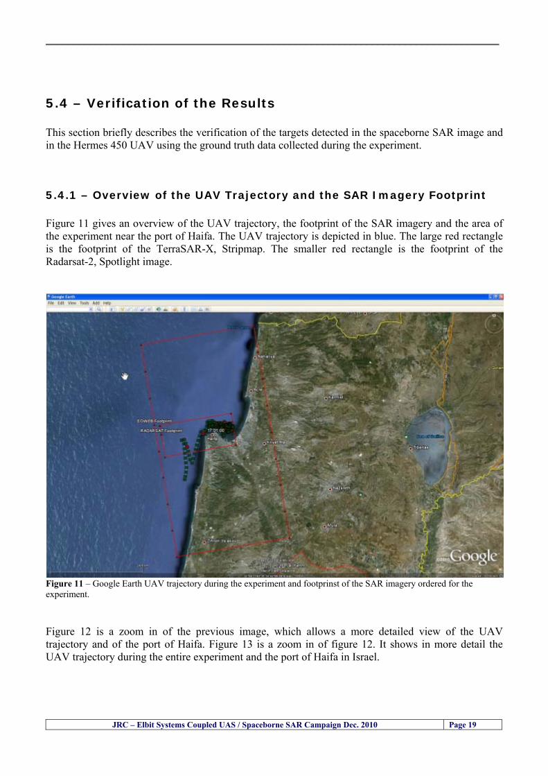
__________________________________________________________________________________
JRC ndash Elbit Systems Coupled UAS Spaceborne SAR Campaign Dec 2010 Page 19
54 ndash Verification of the Results This section briefly describes the verification of the targets detected in the spaceborne SAR image and in the Hermes 450 UAV using the ground truth data collected during the experiment
541 ndash Overview of the UAV Trajectory and the SAR Imagery Footprint Figure 11 gives an overview of the UAV trajectory the footprint of the SAR imagery and the area of the experiment near the port of Haifa The UAV trajectory is depicted in blue The large red rectangle is the footprint of the TerraSAR-X Stripmap The smaller red rectangle is the footprint of the Radarsat-2 Spotlight image
Figure 11 ndash Google Earth UAV trajectory during the experiment and footprinst of the SAR imagery ordered for the experiment Figure 12 is a zoom in of the previous image which allows a more detailed view of the UAV trajectory and of the port of Haifa Figure 13 is a zoom in of figure 12 It shows in more detail the UAV trajectory during the entire experiment and the port of Haifa in Israel
__________________________________________________________________________________
Figure 12 ndash Zoom in of the previous figure showing a more detailed view of the UAV trajectory and of the port of Haifa in Israel
Figure 13 ndash Zoom in of the previous figure showing a even more detailed view of the UAV trajectory and of the port of Haifa in Israel
JRC ndash Elbit Systems Coupled UAS Spaceborne SAR Campaign Dec 2010 Page 20
__________________________________________________________________________________
JRC ndash Elbit Systems Coupled UAS Spaceborne SAR Campaign Dec 2010 Page 21
542 ndash Targets Detected in the Radarsat-2 Spotlight Image Figure 14 illustrates the position of the Elbitrsquos boat used as target in the experiment at the approximate time of the SAR Satellite pass by 1547 UTC (1747 LT) The small photo of the boat shows the approximate position of the boat The two small planes show the positions of the UAV immediately before and after the SAR Satellite pass
Figure 14 ndash Google Earth positions of the elbitrsquos boat and the UAV (Hermes450) at the approximate time of the SAR Satellite overpass by 174740 UTC Figure 15 shows the corresponding SAR image (Radarsat-2 Spotlight) acquired during the experiment Pins 1 and 2 represent the positions of the UAV before and after the SAR satellite overpass Pin 3 illustrates the position of the Elbitacutes boat deployed at the time of the satellite overpass At this scale the SAR signature of the boat is not distinguishable from the sea clutter background However zooming in the SAR image the SAR signature can clearly be seen as illustrated in figure 12 The SAR image in figure 12 also shows several SAR signatures of large ships in the area at the time of the satellite overpass
__________________________________________________________________________________
JRC ndash Elbit Systems Coupled UAS Spaceborne SAR Campaign Dec 2010 Page 22
Elbit`s Boat
Figure 15 ndash On the background the SAR image with the two UAV positions before and after the satellite overpass (Pin1 and Pin2) and the Elbitacutes Boat position (Pin3) The small window over the SAR image shows a zoom in of the SAR image where the SAR signature of the Elbitacutes Boat can clearly be seen The top right are of the SAR image also shows SAR signatures of several large ships in the area at the time of the SAR satellite overpass Figure 16 shows the corresponding SAR image (Radarsat-2 Spotlight) acquired during the experiment and the UAV IR images of some of the targets Pins 1 and 2 represent the positions of the UAV before and after the SAR satellite overpass Pin 3 illustrates the position of the Elbitacutes boat deployed at the time of the satellite overpass At this scale the SAR signature of the boat is not distinguishable from the sea clutter background However zooming in the SAR image the SAR signature can clearly be seen as illustrated in figure 13 On the top left the UAV IR image of the Elbitrsquos Boat The SAR image in figure 13 also shows several SAR signatures of large ships in the area at the time of the satellite overpass On the centre left the UAV IR image of a large ship On the centre right the UAV IR image of a large ship On the bottom right the UAV IR image of a large ship All the UAV images were acquired at night in complete darkness from altitudes in the order of 5500 meters Nonetheless the quality and detail of the UAV images allows classification of the targets and in some cases the identification As it can be seen the potential of UAV for maritime surveillance is very promising During the experiment the UAV detected all the boats and ships in the area and tracked some of the boatsships to test the tracking capability The capability of detection and tracking targets is a critical capability for maritime surveillance
__________________________________________________________________________________
JRC ndash Elbit Systems Coupled UAS Spaceborne SAR Campaign Dec 2010 Page 23
Elbitacutes Boat
Elbit`s Boat
Figure 16 ndash Zoom-in of figure 15 with the UAV images of some targets On the top left the UAV IR image of the Elbitrsquos Boat On the centre left the UAV IR image of a large ship On the centre right the UAV IR image of a large ship On the bottom right the UAV IR image of a large ship Figure 17 shows a comparison of the SAR and UAV images with an optical photo taken in Haifa Israel a couple of hours before the SAR satellites overpass Most of the large ships were detected in the SAR image and some of these ships can be identified in the optical photo Some of the ships in the photo left the area before the SAR satellites overpass
__________________________________________________________________________________
JRC ndash Elbit Systems Coupled UAS Spaceborne SAR Campaign Dec 2010 Page 24
Figure 17 ndash Photo taken in Haifa Israel a couple of hours before the SAR satellites overpass This phot shows the large ships moored in the area Most of these large ships were detected in the Radarsat-2 image As expected their positions and orientations were slightly different at the time of the satellite overpass
Elbitacutes Boat
Elbit`s Boat
__________________________________________________________________________________
JRC ndash Elbit Systems Coupled UAS Spaceborne SAR Campaign Dec 2010 Page 25
Figure 18 ndash Photo taken in Haifa Israel a couple of hours before the SAR satellites overpass This phot shows the large ships moored in the area Most of these large ships were detected in the Radarsat-2 image As expected their positions and orientations were slightly different at the time of the satellite overpass Figure 18 illustrates the SAR image and the corresponding google earth image of a small pier in the port of Haifa In the SAR image due to several artefacts it is not possible to detect the 7 small boats moored to the small pier The UAR IR image of the same area clearly shows the 7 small boats with impressive detail taking into account that the image was acquired from an altitude of about 5500 meters A zoom in of the same UAV IR image is shown in figure 19 As it can be seen although the image was acquired from an altitude of about 5500 meters the 7 small boats can be clearly seen with enough detail to allow classification of the type of boat A UAV flight at lower altitude would probably giver a lot more detail and eventually allow the identification of the small boats
__________________________________________________________________________________
JRC ndash Elbit Systems Coupled UAS Spaceborne SAR Campaign Dec 2010 Page 26
Figure 19 ndash UAV IR image of a small pier in the port of Haifa Israel where 7 small boats can be seen with enough detail to allow classification This image was acquired from an altitude of about 5500 meters in the dark
__________________________________________________________________________________
55 ndash Quantitative Analysis of the Spaceborne SAR Image In order to allow a quantitative analysis of the data the spaceborne SAR image was calibrated using ESArsquos NEST software package version 4B The input was the SAR image acquired and the output was the Radiometric Calibration (Sigma Naught (σdeg)) expressed in terms of intensity and in decibel (dB) the Radar Brightness (βdeg) and the Radiometric Normalisation (gamma naught (γdeg))
551 ndash Radarsat-2-Spotlight 08Dec2010 (154740 UTC) Haifa Israel Figure 20 illustrates the Intensity band of a subset of the Radarsat-2Spotlgiht image (08Dec2010)
Figure 20 ndash Radarsat-2 Spotlgiht image (08Dec2010) ndash Sigma Naught (Intensity) band
JRC ndash Elbit Systems Coupled UAS Spaceborne SAR Campaign Dec 2010 Page 27
__________________________________________________________________________________
Figure 21 illustrates the Sigma Naught Coefficient of the Radarsat-2 Spotlgiht image (08Dec2010) expressed in terms of intensity and decibel (dB)
Figure 21 ndash Radarsat-2 Spotlgiht image (08Dec2010) - On the left the Sigma Naught (σdeg) (intensity) and on the right the Sigma Naught (σdeg) (dB)
ormalisation amma Naught (γdeg)) of the Radarsat-2 Spotlgiht image (08Dec2010) expressed in dB
-2 Spotlgiht image (08Dec2010) - On the left the Beta Naught (βdeg) and on the right the Gamma Naught (γdeg) (dB)
Figure 22 illustrates the Radar Brightness (Beta Naught (βdeg)) and the radiometric n(G
Figure 22 ndash Radarsat
JRC ndash Elbit Systems Coupled UAS Spaceborne SAR Campaign Dec 2010 Page 28
__________________________________________________________________________________ Figure 23 shows the Sigma Naught (σdeg) in dB after some colour manipulation and the histogram of the Sigma Naught (σdeg) image
Figure 23 ndash Radarsat-2 Spotlgiht image (08Dec2010) - On the top left the Sigma Naught (σdeg) after colour manipulation to enhance the targets and on the top right the corresponding histogram On the bottom we can see the histogram of the image
Table 6 gives the statistics of the Sigma Naught (σdeg) Radarsat-2 Spotlgiht image (08Dec2010) The Sigma Naught (σdeg) range from -72897 dB up to 23465 dB The Mean value is -16855 dB the Median is -16594 dB and the standard deviation is 7077 dB
JRC ndash Elbit Systems Coupled UAS Spaceborne SAR Campaign Dec 2010 Page 29
__________________________________________________________________________________
JRC ndash Elbit Systems Coupled UAS Spaceborne SAR Campaign Dec 2010 Page 30
Table 6 ndash Statistics of the Radarsat-2 Spotlgiht image (08Dec2010) (154740 UTC)
Statistics Values Unit Only ROI-Mask pixels considered Number of pixels total Number of considered pixels Ratio of considered pixels
No 322394283 322394283
1000
Minimum Maximum
-728974609375 234655818939209
intensity_db intensity_db
Mean Median Std-Dev Coefficient of Variation
-16855686580177853 -1659462338617847 707796800831575
07888765273432338
intensity_db intensity_db intensity_db intensity_db
Checking the radar backscattering coefficient of some targets (small boat and some large ships) detected in the Radarsat-2 Spotlight image we get values ranging from -0379 dB up to 23455 dB The analysis of the Sigma Naught values (σdeg) of the targets and the area around the targets shows a significant contrast
56 ndash Summary of the Preliminary Analysis of the Spaceborne SAR Image This experiment involved two spaceborne SAR images namely a TerraSAR-X Stripmap and one Radarsat-2 Spotlight The TerraSAR-X image was not delivered by DLR due to technical problems The Elbitrsquos boat deployed during the experiment was detected in the Radarsat-2 Spotlight image Several other targets including a set of large ships were also detected Table 7 summarises the characteristics of the SAR image acquired and the targets detected
Table 7 ndash List of SAR Satellite Images acquired during the experiment and detected boats ISRAEL (HAIFA)
Date Time Place Satellite Mode Ground Truth Data Detected Boats
08Dec2010 (PM) Haifa - Israel Radarsat-2 Spotlight GPSPhotosMovies 1 small boat deployed + 9 large ships
Table 8 gives the minimum and maximum Sigma Naught (σdeg) of the targets detected in each SAR image
Table 8 ndash Minimum and maximum Sigma Naught (σdeg) of the targets detected in each SAR image
Date Time UTC (LT)Pass Satellite Image Mode Polarisation Sigma Naught (σdeg) Min Max
29Oct2010528UTC(728AM LT) DES Radarsat-2 Spotlight HH --0379 dB 23455 dB The SAR signatures of the boats deployed were very weak Some possible reasons to explain such weak signatures are the sea state the wind speed the incidence angle and the type and materials Another possible reason is the processing at DLR
__________________________________________________________________________________
JRC ndash Elbit Systems Coupled UAS Spaceborne SAR Campaign Dec 2010 Page 31
6 ndash Preliminary Conclusions The analysis of the results of this coupled UASSpaceborne SAR experiment shows a promising potential for the use of UAS for maritime surveillance UAS can be integrated into the airborne building block of maritime surveillance systems to complement the existing assets increase system performance and improve the overall maritime domain awareness The main perceived maritime security and safety threats comprise piracy terrorist and military threats weapons proliferationsmuggling drugs trafficking illegal immigration unlawful use of containers attacks to critical infrastructures and illegal fishing The main maritime security and safety gaps include a lack of technologies with the capability of detecting small targets (eg small boats) a lack of wide area and persistent maritime surveillance a lack of coordination and information sharing limited interoperability a lack of containers security a lack of persistent surveillance of critical infrastructures and early warning systems Unmanned Aircraft Systems (UAS) are an emerging technology with strong potential to mitigate the above mentioned threats by filing in the main maritime security and safety gaps listed earlier For instance the wide range of potential applications of UAS to maritime surveillance includes but is not limited to
bull detection classification and identification of small boats bull persistent maritime surveillance bull use as communications relays bull persistent surveillance of critical infrastructures bull early warning systems bull COMINT and ELINT collection etc
Table 11 illustrates the mapping of maritime securitysafety threats vs gaps and summarises the main potential applications of UAS to maritime surveillance The above mentioned potential applications of UAS to the Maritime Domain will be addressed in turn in more detail next bull Detection classification and identification of small boats ndash The capability of detecting classifying and identifying small targets (eg small boats) is among the key technologies required to improve maritime domain awareness This capability is critical to mitigate piracy illegal immigration drugs trafficking weapons smuggling illegal fishing terrorism and critical infrastructure Unmanned Aircraft Systems (UAS) provide this capability more efficiently and at a lower cost than any other existing technology bull Persistent maritime surveillance ndash With the continuous improvements of UAS technologies such as platforms sensors collision avoidance systems command and control systems telecommunications etc UAS are increasing their autonomy endurance and flexibility These characteristics are very important for persistent maritime surveillance UAS can be launched from land ships aircraft and technologies to launch UAS from submarines are currently under development UAS have distinct advantages over other existing technologies for persistent maritime surveillance in terms of autonomyendurance (the Global Surveyor has an autonomy of 1 week) cost (eg as the autonomy of UAS increases the number of staff required to operate UAS decreases) risk (eg if the UAS crashes the crew is not at risk) flexibility (eg they can be launched from a ship reducing the time to reach potential threats) etc
__________________________________________________________________________________
JRC ndash Elbit Systems Coupled UAS Spaceborne SAR Campaign Dec 2010 Page 32
bull Communications relays ndash UAS are being used as communication relays mainly in military context but have the potential to play a similar role in Civil context in several situations such as to replace satellite communications or as a redundant system over any location on Earth The main advantages of using UAS as communication relays is that airborne communication relays mitigate kinetic and noise jamming threats to satellite communications uplinks by providing an alternative set of links either directly to surface-based terminals or to satellites beyond the range of threats They are less susceptible to noise jamming threats than satellites because an adversary has to detect geolocate and track the airborne asset and operate within line of sight of the receive antenna main beam bull Persistent surveillance of critical infrastructures ndash The security of critical infrastructures such as nuclear power plants refineries ports etc requires persistent surveillance UAS can play an important role in providing persistent surveillance over critical infrastructures and over a wide area around the critical infrastructure Some advantages of UAS over other existing technologies such as ground-based assets (eg video cameras alarm systems manned aircraft etc) comprise the security of the UAS (eg hardly can be damaged or switched off as any ground-based asset) the area covered by a UAS (eg it is larger than the area covered by any ground-based asset) the cost (eg UAS is cheaper than manned aircraft with similar capability) etc bull Early warning systems ndash UAS have the potential to be used as part of an integrated system of systems for early warning A UAS can provide information about a given area at a fraction of the cost of alternative means Formation flying of UAS can cover a wide maritime area It is reasonable to assume that in a foreseeable future with the advent of UAS with increased autonomy the operations cost of UAS will likely decrease making them increasingly more attractive bull COMINT and ELINT collection ndash SIGNal INTelligence (SIGNINT) can be divided into two categories namely COMINT and ELINT COMINT stands for Communication Intelligence and ELINT for Electronic Intelligence Collection of COMINT is passive Exploitation of COMINT requires a human operator which implies COMINT UAS are suitable for COMINT and ELINT collection in different scenarios The relatively reduced amount of data collected and analysed during this experiment and the lessons learned do not allow drawing final conclusions about the feasibility of using Unmanned Aerial Systems (UAS) for maritime surveillance However this experiment allowed hands-on experience with UAS technologies and significantly improved the awareness for its applications to maritime surveillance and related issues involved including its potential the feasibility as well as the limiting and enabling factors These different aspects will now be analysed in turn in the next sections Table 11 illustrates the mapping of the main maritime security threats and gaps as well as the main priorities in terms of the different technologies involved in maritime surveillance For each maritime threat the technologies required to fill in each gap is indicated and its priority is expressed in a range of numbers (1 to 3 1 = Maximum Priority 2 = Medium Priority 3 = Low Priority) and colours (Red = Maximum Priority Orange = Medium Priority Green = Low Priority) The main technologies involved in maritime surveillance are listed on the bottom of figure 4 and are reproduced here for convenience of the reader 1- Reporting Systems 2- Sensors 3- Platforms 4- Communications 5- Data Fusion amp Sharing 6- Intelligence and 7- Databases For example the mitigation of the main threat Piracy requires filling in several maritime security gaps (eg lack of persistent surveillance lack of wide-are maritime surveillance lack of small boat detection lack of Early Warning Systems and lack of Information Sharing with maximum priority (1- Red) and among the required technologies listed are UAS LTAAV GEO-HR etc Concerning the remaining two gaps (Limited Interoperability and Containers Security) they are less relevant to mitigate Piracy hence the priority for Limited Interoperability is 2-Orange and for Containers Security is 3- Green
__________________________________________________________________________________ Table 9 ndash The Main Maritime Security and Safety Threats vs Gaps and the technologies that can be used to mitigate them
Maritime Security Main Threats GapsGapsrarr
darrThreats
Lack o f Risk As sessmentCapab ility
La ck of Persiste nt
Surveilla nce
La ck of Wid e-Area su rve illanc e
La ck of Small Boat De tecti on
Lack o f Earl y Warn ing Sys tems
L ack of In forma tion
Sh arin g
L imi ted In terop era bility
Lac k of Co ntai ners
Se cur ity
bull PiracyUAS LTAVG EO-
HR + UAS LT AVGEO-
HR + SAR GEO-HR
+ UAS USV LTAV
+ UAS LTAV
+ Coord in ationamp Sharing +
Inter opera bilityOptimisation +
1 2 3 5 6 7 1 2 3 5 6 7 1 2 3 5 6 1 2 3 123456 4567 1234567 1234567
bull Terro rismUAS LTAVG EO-
HR + UAS L TAV GEO-HR +
SAR AISGEO-HR +
UAS USV LTAV+
Intelligence+
Inte lligen ce+
Inter opera bilityOptimisation +
Intelligence+
1 2 3 5 6 7 1 2 3 5 6 1 2 3 5 6 1 2 3 123456 4567 1234567 1234567
bull Wea pon s ofM ass Dest ru ctio n Smugg ling
UAS LTAVG EO-HR +
UAS LT AVGEO-HR +
SAR AIS+
UAS USV LTAV+
Intelligence+
Inte lligen ce+
Intelligence+
Intelligence+
1 2 3 5 6 7 1 2 3 5 6 1 2 3 5 6 1 2 3 123456 4567 1234567 1234567
bull Drug sTraffic king
UAS LTAVG EO-HR +
UAS LT AVGEO-HR +
SAR AIS+
UAS USV LTAV+
Intelligence+
Inte lligen ce+
Intelligence+
Intelligence+
1 2 3 5 6 7 1 2 3 5 6 1 2 3 5 6 1 2 3 123456 4567 1234567 1234567
bull Illega lImmigratio n
UAS LTAVG EO-HR +
UAS LT AVGEO-HR +
SAR AIS+
UAS USV LTAV+
Intelligence+
Inte lligen ce+
Intelligence+
Intelligence+
1 2 3 5 6 7 1 2 3 5 6 1 2 3 5 6 1 2 3 123456 4567 1234567 1234567
bull Critic alI nfrastruc tureSecu rit y
UAS LTAVG EO-HR +
UAS LT AVGEO-HR +
SAR AIS+
UAS USV LTAV+ + Inte lligen ce
+ Intelligence
+ Intelligence
+
1 2 3 5 6 7 1 2 3 6 1 2 3 5 6 1 2 3 123456 4567 1234567 1234567
bull Illega lFish ing
UAS LTAVG EO-HR +
AI S+SAR UASLTAV +
SAR AIS GEO-HR+
UAS USV LTAV+
Intelligence+
Inte lligen ce+
Intelligence+
1 2 3 5 6 7 1 2 3 5 7 1 2 3 5 6 1 2 3 123456 4567 1234567
bull Un lawf ul Use of Co nta iners
(Secur ity)
UAS LTAVG EO-HR +
GPS Tr acking+
Intelligence+
Inte lligen ce+
GPS Int rusion Det ection Se al
1 2 3 5 6 7 4 6 7 1 2 3 5 6 1 2 3 123456 4567 1234567 1234567
(-) Priority (+) Not Rel evant
SURVEILLANCETECHNOLOGIES
1- Reporti ng Systems
2 -Sensors 3 -P latforms 4 - Communications 5- Data Fusionamp Sharing
6 -I ntelli gence 7 -Databases
JRC ndash Elbit Systems Coupled UAS Spaceborne SAR Campaign Dec 2010 Page 33
__________________________________________________________________________________
JRC ndash Elbit Systems Coupled UAS Spaceborne SAR Campaign Dec 2010 Page 34
61 ndash Hands-on experience with UAS technologies and its applications to maritime surveillance This coupled UASSpaceborne SAR campaign was a unique opportunity to acquire further handsndashon experience with UAS technologies and learn about the main issues related to its applications to maritime surveillance From the planning phase up to the execution of the UAS flight and landing there are several factors that need to be carefully analysed and taken into account A summary of the main issues identified in this experiment is given next 1- Selection of the Experiment Area Authorisation to Fly ndash For the time being UAS can only be flown in restricted areas usually under control of national authorities often the military This is due to the risks that a UAS can pose to human life and property In the present case an area under the authority of the Israeli Civil Aviation Authority was selected The authorisation to fly was not easy to obtain because the selected area is under the authority of the Civil Aviation Authority Figure 24 indicates the area of the experiment in Haifa Israel 2- UAS Communications Issues ndash The Hermes 450 was flown in Line-of-Sight (LOS) since it was close to the coast For BLOS (Beyond Line-of-Sight) operation satellite communications are required 3- Synthetic Aperture Radar (SAR) ndash The specific model Hermes 450W used in the experiment had no SAR sensor installed However a SAR sensor can be installed A SAR sensor is important for maritime surveillance since it allows 247 operations regardless of the weather conditions 4- Automatic Identification System (AIS) Receiver ndash The Hermes 450 used in this experiment was not equipped with an AIS receiver For maritime surveillance operations an AIS receiver is a very important tool since it allows the automatic identification of most ships allowing the UAS to concentrate on non-identified ships
__________________________________________________________________________________
Figure 24 ndash The area of the experiment is indicated by the GPS Trajectory of the UAV
62 ndash Potential of UAS for Maritime Surveillance UAS technologies are relatively recent and involve a wide range of fields spanning from aeronautics and sensors technologies to satellite communications and other engineering disciplines Innovations in each of the fields involved are emerging by the day UAS still have a long way to go before they become mature and their use fully operational For the time being UAS are mainly used for military applications However a large number of non-military UAS applications have been identified by stakeholders and there are several studies and demonstration flights foreseen for the near future Maritime surveillance is one of the most challenging and promising fields of application of UAS The challenges are due to the very demanding conditions under which the UAS must operate over sea and the requirements for safe operation
JRC ndash Elbit Systems Coupled UAS Spaceborne SAR Campaign Dec 2010 Page 35
__________________________________________________________________________________
JRC ndash Elbit Systems Coupled UAS Spaceborne SAR Campaign Dec 2010 Page 36
The present UAS experiment has unveiled some of the potential of UAS for maritime surveillance The UAS tests performed during this experiment include
1 ndash Detection of a Small rubber Boat and a Fishing Ship 2 ndash Tracking of a Small Boat and a Fishing Ship 3 ndash Classification of a Small Boat and a Fishing Ship 4 ndash Identification of a Small Boat and a Fishing Ship 5 ndash Detection and Tracking of People on the Beach
Despite the operational requirement that prevented the UAS from flying bellow 3km the experiment has confirmed the capability of UAS for small boat detection tracking and classification as well as the capability for people detection and tracking Concerning the identification of the targets the characteristics of the images acquired during this mission suggest that flying at lower altitudes the UAS images would allow the identification of the targets The UAS images can be seen from Figure 15 to 20
621 ndash Advantages of UAS for maritime Surveillance Some of the advantages of using UAS for maritime surveillance have been described in the literature and are summarized bellow
1- One potential benefit of UAS is that they could fill in a gap in current maritime surveillance by improving coverage
2- The range of UAS is a significant asset when compared to border agents on patrol or stationary surveillance equipment
3- Eletro-Optical InfraRed (EOIR) sensors (cameras) can identify small size objects from very high altitudes (high resolution)
4- UAS can provide precise and near-real-time imagery to a ground control operator who would then disseminate that information so that informed decisions regarding the deployment of border patrol agents can be made quickly
5- Long endurance UAS used along the border can fly for more than 30 hours up to several days without having to refuel compared with manned helicopterrsquos average flight time of just over 2 hours
6- The ability of UAS to loiter for prolonged periods of time has important operational advantages over manned aircraft
7- The longer flight times of UAS means that sustained coverage over a previously exposed area may improve maritime security
8- The range of UAVs is a significant asset when compared to border agents on patrol or stationary surveillance equipment Nevertheless the extended range and endurance of UAVs may lessen the burdens on human resources at the borders
9- UAS accidents do not risk the lives of pilots as do the helicopters and aircraft currently used by Coast Guards for border patrolling
__________________________________________________________________________________
JRC ndash Elbit Systems Coupled UAS Spaceborne SAR Campaign Dec 2010 Page 37
622 ndash Possible Drawbacks of using UAS for maritime Surveillance UAS also have disadvantages some of them are briefly described next
1- There have been concerns regarding the high accident rate of UAS which can be multiple times higher than that of manned aircraft Because UAS technology is still evolving there is less redundancy built into the operating system of UAS than of manned aircraft and until redundant systems are perfected mishap rates are expected to remain high
2- If control systems fail in a manned aircraft a well-trained pilot is better positioned to find the source of the problem because of hisher physical proximity If a UAS encountered a similar system failure or if a UAS landing was attempted during difficult weather conditions the ground control pilot would be at a disadvantage because he or she is removed from the event Unlike a manned pilot the remote pilot would not be able to assess important sensory information such as wind speed
3- Inclement weather conditions can also impinge on a UAS surveillance capability especially UAS equipped with only an EO camera and Forward Looking Infrared Radar (FLIR) because cloudy conditions and high humidity climates can distort the imagery produced by EO and FLIR equipment The effects of extreme climatic or atmospheric conditions on sensors reportedly can be mitigated with the outfit of one synthetic aperture radar (SAR) system and a moving target indicator (MTI) radar However adding SAR and MTI to a UAS platform would increase the costs associated with using UAS
4- Depending on the type of UAS the costs of operating a UAS can be higher than the costs of operating a manned aircraft This is because some types of UAS require a significant amount of logistical support and specialized operator and maintenance training Operating one UAS may require a crew of up to 20 support personnel The high comparative costs of operating some sophisticated types of UAS may be offset somewhat by their comparatively lower unit costs
63 ndash Main Limiting Factors Preventing the Use of UAS Several pre-requisites must be satisfied to render the UAS a viable cost-effective and regulated alternative to existing resources Major civil and commercial market barriers include
Single European Sky Sense and Avoid technologies Command and Control Technologies Reliability Communications (Bandwidth LOS BLOS)
Lack of airspace regulation that covers all types of UAV systems (encompassing lsquosense and avoidrsquo airspace integration and airworthiness issues)
Affordability - price and customization issues (eg commercial off-the-shelf open modular architecture) Lack of efforts to establish joint customer requirements (although this is gradually changing) Liability for civil operation Capacity for payload flexibility Lack of sufficient secure non-military frequencies for civil operation Perceived reliability (eg vehicle attrition rate vs manned aircraft) Operator training issues Recognitioncustomer perception of the UAV market Technology developments for multi-mission capability
__________________________________________________________________________________
64 ndash UAS Key Enabling Technologies Figure 25 illustrates the components of a typical UAV System showing some of the capabilities needed and the enabling technologies required for performing a given mission Any UAV mission involves many capabilities and technologies Due to the depicted system complexity the main key players such as the US Department of Defense (DoD) and other agencies have started to use the term Unmanned Aerial System (UAS) in place of UAV
Figure 25 ndash Unmanned Aerial Vehicle System Enabled by Autonomous Mission Management Reliable Flight Systems Navigation Accurate Systems Terrain Avoidance Power and Propulsion Some UAS key enabling technologies are listed below
Autonomous Mission Management Collision Avoidance Intelligent System Health Monitoring
Reliable Flight Systems Sophisticated Contingency Management Intelligent Data Handling and Processing Over-the-Horizon Communication Network-Centric Communication Open Architecture Power and Propulsion Navigation Accurate System Technology Enhanced Structures
JRC ndash Elbit Systems Coupled UAS Spaceborne SAR Campaign Dec 2010 Page 38
__________________________________________________________________________________
JRC ndash Elbit Systems Coupled UAS Spaceborne SAR Campaign Dec 2010 Page 39
Table 12 gives a more detailed description of other critical technologies for emerging autonomous UAV systems both civil and military Most of the technologies mentioned in Table 12 apply both to civil and military UAV systems Table 10 ndash Key Enabling Technologies (from SG75 study on autonomous systems)
Critical Technologies Decision Making Software
bull Fuzzy-based decision making bull Knowledge-based system bull Case-based reasoning bull Self-learning techniques bull Decision tree evaluation bull ReasoningInferring bull Probabilisticstochastic reasoning
Prediction Algorithms bull Predictive pathintent algorithms bull Short reaction algorithm bull Effectiveness evaluation
Status Assessment Software bull Internal status analysis bull Self-orientation
Situation Analysis Software bull Situation analysis bull Environmental analysis bull External status analysis
Modelling Software bull Air vehicle modelling algorithms bull Sensor modelling algorithms bull Scenario generation bull Threat system modeling bull Attack simulation bull Mission success optimisation model bull Simulation
Sensor Processing Software bull Sensor fusion bull Area of interest identification bull Automatic target recognition
Adaptive and Self-learning Systems bull Failure self-compensation
Attack Planning Software bull Attack plans and tactical alternatives bull Plan change impact identification
Weapon Engagement Procedure Software bull Weapon engagement algorithms
Mission Plan Update Software bull Route planning system bull Payload plan management system bull Mission Success Optimisation model
Path Optimisation Software bull Optimal trajectory planning bull Path Optimisation System
Targeting Software bull Target tracking bull Target prioritisation
Platform Technologies bull Obstacle detection and avoidance (airborne) bull Obstacle detection and avoidance (ground) bull Improved autopilot bull Speech recognition
Figure 26 summarises system element designs needed to transition from current to next-generation autonomous UAV systems for civilian and military UAS
__________________________________________________________________________________
Figure 26 ndash System Element Designs Needed to Transition from Current to Next-Generation Autonomous UAV Systems These new paradigms are a combination of system attributes and technological capabilities For instance the data fusion secure anti-jam and coordinated multi-vehicle control require technological development as well as specific system development to bring full maturity to unmanned systems Finally very small Micro UAVs (MAVs) and relatively large sophisticated UCAV systems are examples of the range of UAVs that are applying the new platforms payloads onboard processing communications etc to create next generation automated UAVs It is with these new platforms payloads etc that both UCAVs and MAV will be able to address similar operational challenges including
Mixed operation with other assets bull Deconfliction collision avoidance C4I integration
Operation over populated areas bull Safety issues Need to reduce reliance on communications bull UCAV ndash countermeasures bull MAV ndash limited size and power bull Limited line of sight environment Need a fully integrated system bull MAV propulsionpower generation still critical bull Operator machine interface critical bull All weather operations bull Survivability
JRC ndash Elbit Systems Coupled UAS Spaceborne SAR Campaign Dec 2010 Page 40
__________________________________________________________________________________
JRC ndash Elbit Systems Coupled UAS Spaceborne SAR Campaign Dec 2010 Page 41
65 ndash Mission Readiness
651 ndash Mission Readiness Summary This section summarises civil UAV mission readiness The purpose of Mission Readiness is to assess the readiness status of the different technologies involved in UAS In the present case this civil UAV mission readiness based on technology maturation forecasts that meet or exceed the desired or required capabilities identified by the user community Figure 27 summarises the mission readiness time forecasts for the different technologies The technologies annotated with an asterisk () are shown within the figure with maturation forecasts based on development targets expressed in the US Department of Defencesrsquo UAV Roadmap document The purpose of the chart is to be able to identify when the capability to fly a particular mission can be expected as a function of time The left-most end is the least probable and the right end the most probable timeframe
Figure 27 ndash Technology Maturation Summaries in Terms of Mission-Derived Capabilities
__________________________________________________________________________________
JRC ndash Elbit Systems Coupled UAS Spaceborne SAR Campaign Dec 2010 Page 42
66 ndash Small Boat Detection in SAR Satellite Imagery The use of spaceborne SAR imagery for small boat detection requires additional small boat detection experiments under different conditions using different methods It is not possible to draw final conclusions based on a limited number of small boat detection experiments which are not representative of the multiple possible scenarios
67 ndash Limitations of current State-of-the-Art SAR Satellite technology The main limitations of current State-of-the-Art spaceborne SAR imagery for maritime surveillance in particular aimed at small boat detection are 1 - SAR satellites repeat cycles do not allow the coverage of the same area at the required time intervals Constellations of SAR satellites could be a solution 2 - The conflict between resolution and image swath High resolution is required to detect small boats However the high resolution images have small swaths Maritime surveillance with high resolution images would require a large number of images to cover wide maritime areas which is very expensive and for the time being technically not feasible Intelligence data can play an important role by indicating an approximate position of suspicious non cooperative targets therefore reducing the surveillance area which can then be imaged using high resolution images 3- Spaceborne high resolution SAR imagery acquisition times are long enough to allow significant motion of the target during the acquisition time degrading the quality of the image Further research efforts are needed to develop new sensors and platforms As far as sensors are concerned shorter integration times are needed to prevent the blurring effect caused by the motion of the targets Regarding the platforms more platforms are needed to allow lower repeat cycles and improved coverage
__________________________________________________________________________________
JRC ndash Elbit Systems Coupled UAS Spaceborne SAR Campaign Dec 2010 Page 43
7 ndash Plans for Future Work The controlled experiments carried out by the EC-JRC together with Elbit Systems in Haifa-Israel comprised the deployment of a UAS (Hermes-450) and one small 12-meter boat A Radarsat-2 Spotlight image was acquired and several images collected by the Hermes-450 The experiment unveiled the potential of UAS for maritime surveillance in particular for detection tracking classification and possible identification of small targets The UAS was able to detect track and classify small targets such as small boats For low UAS altitude flights identification may be possible in some cases The small 12-meter boat was detected in the spaceborne SAR image The small boat detection trials carried out by the JRC were very successful since most small boats deployed during the experiments were detected in different sea states wind speeds and geographical locations The several small boat detection campaigns conducted by the EC-JRC seem to suggest that the probability of detection of small boats in spaceborne SAR images strongly depends on factors such as the sea state the wind speed the type of boat (shape and materials) the weather conditions among other factors The results of the experiments conducted thus far are not enough to draw final conclusions about the feasibility of using spaceborne SAR imagery for small boat detection However the experiments have an overall positive outcome because they indicate that under suitable sea state and wind speed conditions it is possible to detect small boats using spaceborne SAR The estimation of the probability of detection of small boats in spaceborne SAR images requires a large number of experiments under different circumstances (eg sea state wind speed characteristics of the targets image type and mode etc) Future plans include additional UAS experiments to asses its potential for maritime surveillance
Acknowledgements ndash The authors would like to express their gratitude to Elbit Systems for their cooperation logistical support and assets deployed without which the present coupled UASSAR Satellite Small Boat Detection Campaign would have not been possible
__________________________________________________________________________________
JRC ndash Elbit Systems Coupled UAS Spaceborne SAR Campaign Dec 2010 Page 44
REFERENCES [1] Elbit Systems ldquoUAV Elbit Systems Proposal for Unmanned Aerial Vehicle (UAV) flight to
collect Ground Truth data during a Maritime Surveillance Campaign and demonstrate UAV capabilities for Maritime Surveillancerdquo 2010
[2] ndash Cheryl Yuhas Suborbital Science Program Manager NASA Science Mission Directorate ldquoEarth Observations and the Role of UAVs A Capabilities Assessment Version 11rdquo Civil UAV Assessment Team httpwwwnasagovcentersdrydenresearchcivuavindexhtml August 2006
[3] ndash Document NIAG (SG75) NATO Industrial Advisory Group Study Group 75 Pre-Feasibility Study on UAV Autonomous Operations 2004
[4] ndash United States Department of Defence (DoD) Directive 50001 ldquoThe Defense Acquisition Systemrdquo and DoD Instruction 50002 ldquoOperation of the Defense Acquisition Systemrdquo
[5] ndash Mr James Ramage Mr Massimo Avalle Dr Erik Berglund Dr Luigi Crovella Mr Robert Frampton Dr Uwe Krogmann Mr Christian Ravat Mr Mike Robinson Dr Axel Schulte Dr Scott Wood ldquoRTO-TR-SCI-118 - Automation Technologies and Application Considerations for Highly Integrated Mission Systemsrdquo RTO-TR-SCI-118 AC323(SCI-118)TP204 January 2009
[6] Victor MG Silva Gilles Jurquet Gabriel Marchalot Maria TG Calzado Txema Soroa Juan Sancho Adam Koubek Harm Greidanus and Claudio Savarino ldquoWide Maritime Area Airborne Surveillance (WIMA2S) WP5 Final Reportrdquo WIMAAS WP5 FP7 Project 2008-2011 - ISBN-978-92-79-22801-8 (print) 978-92-79-22802-5 (PDF) ISSN-1018-5593 (print) 1831-9424 (online) EC-JRC Scientific Report JRC 70093 2012
[7] Victor MG Silva and Harm Greidanus ldquoSpaceborne SAR Small Boat Detection Campaign in Portugal and Spainrdquo EUR 25281 EN ISBN 978-92-79-22553-6 ISSN 1831-9424 (online) EC-JRC Scientific Report JRC68160 2012
[8] Goncalves Da Silva V Van Wimersma Greidanus H Hejmanowska B Loudjani P ldquoUAS Applications With Societal Benefits ndash JRCrsquos UAS-Related Activitiesrdquo 2011-2012 UAS Yearbook - UAS Unmanned Aircraft Systems - The Global Perspective 9 (9) 2011 p 127-129 JRC66600
[9] Goncalves Da Silva V Van Wimersma Greidanus H ldquoSmall boat detection using TerraSAR-X and Radarsat2 satellite imageryrdquo 4th TerraSAR-X Science Team Meeting 14 February 2011 DLR Oberpfaffenhofen (Germany) German Aerospace Center (DLR) (Organiser) 2011 JRC63663
[10] V Silva Harm Greidanus ldquoJRC - SAR Satellite Small Boat Detection Campaign - Portoroz ndash Sloveniardquo - ISBN-13 978-92-79-21476-9 ISSN (online) 1831-9424 EC-JRC Scientific Report JRC66835 2011
[11] V Silva Harm Greidanus ldquoJRC - SAR satellite small boat detection campaign - Algarve Portugalrdquo - ISBN-13 978-92-79-21265-9 ISSN (online) 1831-9424 ISSN (print) 1018-5593 EC-JRC Scientific Report JRC66631 2011
[12] ndash Goncalves Da Silva V Van Wimersma Greidanus H ldquoJRC-Frontex Spaceborne SAR Small Boat Detection Campaign ndash Italy amp Spainrdquo - ISBN-13 978-92-79-22213-9 ISSN (online) 1831-9424 EC-JRC Scientific Report JRC67517 2011
[13] - PW Vachon SJ Thomas J Cranton HR Edel and MD Henschel Validation of ship detection by the RADARSAT synthetic aperture radar and the Ocean Monitoring Workstation Canadian Journal of Remote Sensing 26(3)200ndash212 2000
[14] - Crisp D (2004) The state-of-the-art in ship detection in Synthetic Aperture Radar imagery DSTO Information Sciences Laboratory Australia
[15] - Joint Research Centre (JRC) of the European Community mdash IMPAST and DECLIMS web site httpintelligencejrcceceuintmarinefishindexhtm
[16] - McCandless SW Jackson CR (2004) Principles of Synthetic Aperture Radar Synthetic Aperture Radar Marine Users Manual NOAA Washington pp 1-23
[17] - Greidanus H (2008) Satellite Imaging for Maritime Surveillance of the European Seas Remote Sensing of the European Seas 343-358
European Commission
EUR 25346 EN --- Joint Research Centre --- Institute for the Protection and Security of the Citizen
Title JRC --- Elbit Systems Coupled UAS and Spaceborne SAR Campaign in Israel
Authors Victor MG Silva Harm Greidanus
Luxembourg Publications Office of the European Union
2012 --- v+44 pp --- 210 x 297 cm
EUR --- Scientific and Technical Research series --- ISSN 181-9424 (online) ISSN 1018-5593 (print)
ISBN 978-92-79-25020-0
doi10278828527
Abstract The European maritime area is one of Europersquos most important assets with regard to resources security and ultimately
prosperity of the Member States A significant part of Europersquos economy relies directly or indirectly on it It is not just the
shipping or fisheries industries and their related activities It is also shipbuilding and ports marine equipment and offshore
energy maritime and coastal tourism aquaculture submarine telecommunications blue biotech and the protection of the
marine environment The European maritime area faces several risks and threats posed by unlawful activities such as drugs
trafficking smuggling illegal immigration organised crime and terrorism Piracy in international waters also constitutes a threat
to Europe since it can disrupt the maritime transport chain These risks and threats can endanger human lives marine resources
and the environment as well as significantly disrupt the transport chain and global and local security It is anticipated that these
risks and threats will endure in the mid and long run In order to keep Europe as a world leader in the global maritime economy
an effective integratedinteroperable sustainable maritime surveillance system and situational awareness are needed
A significant number of unlawful maritime activities such as illegal immigration drugs trafficking smuggling piracy and
terrorism involve mainly small boats because small boats are faster and more difficult to detect using conventional means
Hence it is very important to find out the feasibility of using Unmanned Aerial Systems (UAS) for small boat detection tracking
classification and identification as well as to study the potential of UAS for maritime surveillance Since 2010 the EC-JRC has
carried out a number of UAS maritime surveillance campaigns to study the potential of UAS for maritime surveillance in
particular for small boat detection This report presents the results and conclusions of the JRC --- Elbit Systems Coupled UAS and
Spaceborne SAR campaign carried out in Dec 2010 in Haifa Israel
As the Commissionrsquos in-house science service the Joint Research Centrersquos mission is to provide EU policies with independent evidence-based scientific and technical support throughout the whole policy cycle Working in close cooperation with policy Directorates-General the JRC addresses key societal challenges while stimulating innovation through developing new standards methods and tools and sharing and transferring its know-how to the Member States and international community Key policy areas include environment and climate change energy and transport agriculture and food security health and consumer protection information society and digital agenda safety and security including nuclear all supported through a cross-cutting and multi-disciplinary approach
LB-NA-25346-EN
-N
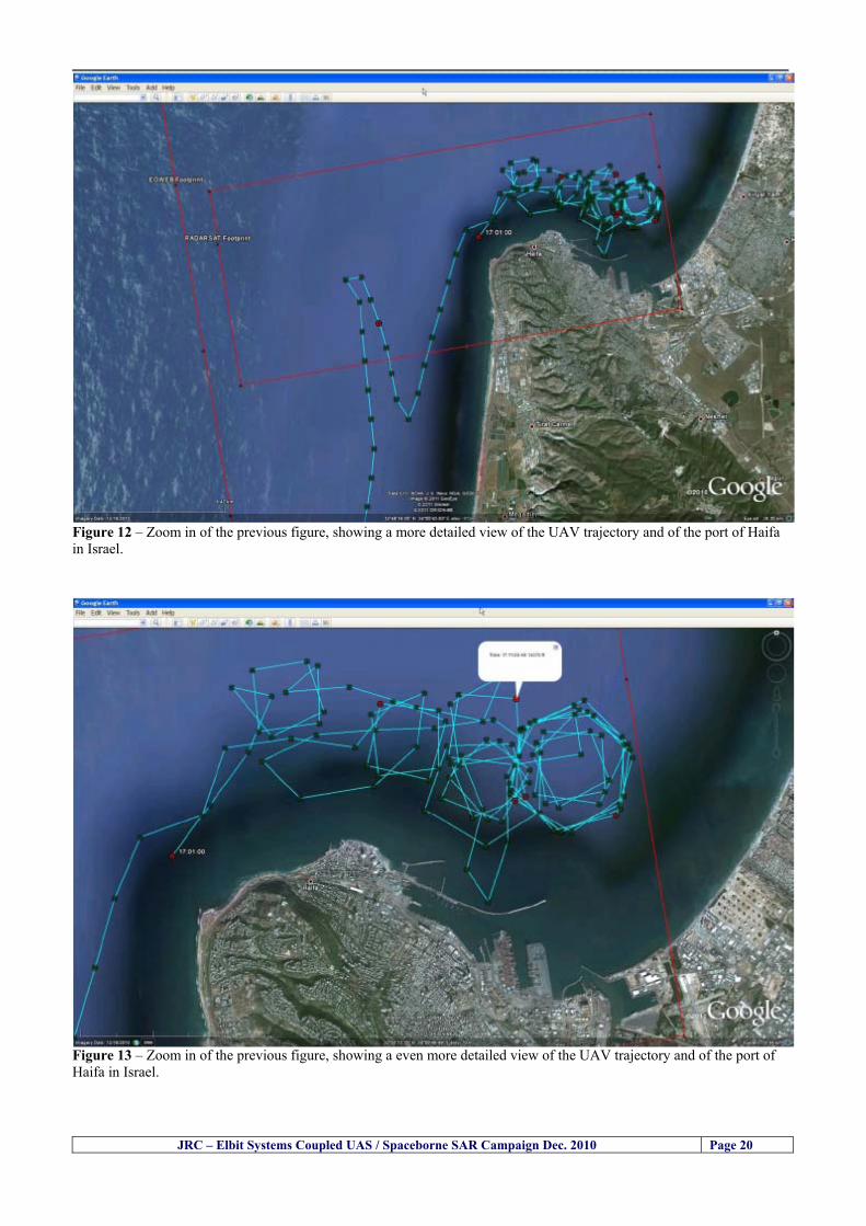
__________________________________________________________________________________
Figure 12 ndash Zoom in of the previous figure showing a more detailed view of the UAV trajectory and of the port of Haifa in Israel
Figure 13 ndash Zoom in of the previous figure showing a even more detailed view of the UAV trajectory and of the port of Haifa in Israel
JRC ndash Elbit Systems Coupled UAS Spaceborne SAR Campaign Dec 2010 Page 20
__________________________________________________________________________________
JRC ndash Elbit Systems Coupled UAS Spaceborne SAR Campaign Dec 2010 Page 21
542 ndash Targets Detected in the Radarsat-2 Spotlight Image Figure 14 illustrates the position of the Elbitrsquos boat used as target in the experiment at the approximate time of the SAR Satellite pass by 1547 UTC (1747 LT) The small photo of the boat shows the approximate position of the boat The two small planes show the positions of the UAV immediately before and after the SAR Satellite pass
Figure 14 ndash Google Earth positions of the elbitrsquos boat and the UAV (Hermes450) at the approximate time of the SAR Satellite overpass by 174740 UTC Figure 15 shows the corresponding SAR image (Radarsat-2 Spotlight) acquired during the experiment Pins 1 and 2 represent the positions of the UAV before and after the SAR satellite overpass Pin 3 illustrates the position of the Elbitacutes boat deployed at the time of the satellite overpass At this scale the SAR signature of the boat is not distinguishable from the sea clutter background However zooming in the SAR image the SAR signature can clearly be seen as illustrated in figure 12 The SAR image in figure 12 also shows several SAR signatures of large ships in the area at the time of the satellite overpass
__________________________________________________________________________________
JRC ndash Elbit Systems Coupled UAS Spaceborne SAR Campaign Dec 2010 Page 22
Elbit`s Boat
Figure 15 ndash On the background the SAR image with the two UAV positions before and after the satellite overpass (Pin1 and Pin2) and the Elbitacutes Boat position (Pin3) The small window over the SAR image shows a zoom in of the SAR image where the SAR signature of the Elbitacutes Boat can clearly be seen The top right are of the SAR image also shows SAR signatures of several large ships in the area at the time of the SAR satellite overpass Figure 16 shows the corresponding SAR image (Radarsat-2 Spotlight) acquired during the experiment and the UAV IR images of some of the targets Pins 1 and 2 represent the positions of the UAV before and after the SAR satellite overpass Pin 3 illustrates the position of the Elbitacutes boat deployed at the time of the satellite overpass At this scale the SAR signature of the boat is not distinguishable from the sea clutter background However zooming in the SAR image the SAR signature can clearly be seen as illustrated in figure 13 On the top left the UAV IR image of the Elbitrsquos Boat The SAR image in figure 13 also shows several SAR signatures of large ships in the area at the time of the satellite overpass On the centre left the UAV IR image of a large ship On the centre right the UAV IR image of a large ship On the bottom right the UAV IR image of a large ship All the UAV images were acquired at night in complete darkness from altitudes in the order of 5500 meters Nonetheless the quality and detail of the UAV images allows classification of the targets and in some cases the identification As it can be seen the potential of UAV for maritime surveillance is very promising During the experiment the UAV detected all the boats and ships in the area and tracked some of the boatsships to test the tracking capability The capability of detection and tracking targets is a critical capability for maritime surveillance
__________________________________________________________________________________
JRC ndash Elbit Systems Coupled UAS Spaceborne SAR Campaign Dec 2010 Page 23
Elbitacutes Boat
Elbit`s Boat
Figure 16 ndash Zoom-in of figure 15 with the UAV images of some targets On the top left the UAV IR image of the Elbitrsquos Boat On the centre left the UAV IR image of a large ship On the centre right the UAV IR image of a large ship On the bottom right the UAV IR image of a large ship Figure 17 shows a comparison of the SAR and UAV images with an optical photo taken in Haifa Israel a couple of hours before the SAR satellites overpass Most of the large ships were detected in the SAR image and some of these ships can be identified in the optical photo Some of the ships in the photo left the area before the SAR satellites overpass
__________________________________________________________________________________
JRC ndash Elbit Systems Coupled UAS Spaceborne SAR Campaign Dec 2010 Page 24
Figure 17 ndash Photo taken in Haifa Israel a couple of hours before the SAR satellites overpass This phot shows the large ships moored in the area Most of these large ships were detected in the Radarsat-2 image As expected their positions and orientations were slightly different at the time of the satellite overpass
Elbitacutes Boat
Elbit`s Boat
__________________________________________________________________________________
JRC ndash Elbit Systems Coupled UAS Spaceborne SAR Campaign Dec 2010 Page 25
Figure 18 ndash Photo taken in Haifa Israel a couple of hours before the SAR satellites overpass This phot shows the large ships moored in the area Most of these large ships were detected in the Radarsat-2 image As expected their positions and orientations were slightly different at the time of the satellite overpass Figure 18 illustrates the SAR image and the corresponding google earth image of a small pier in the port of Haifa In the SAR image due to several artefacts it is not possible to detect the 7 small boats moored to the small pier The UAR IR image of the same area clearly shows the 7 small boats with impressive detail taking into account that the image was acquired from an altitude of about 5500 meters A zoom in of the same UAV IR image is shown in figure 19 As it can be seen although the image was acquired from an altitude of about 5500 meters the 7 small boats can be clearly seen with enough detail to allow classification of the type of boat A UAV flight at lower altitude would probably giver a lot more detail and eventually allow the identification of the small boats
__________________________________________________________________________________
JRC ndash Elbit Systems Coupled UAS Spaceborne SAR Campaign Dec 2010 Page 26
Figure 19 ndash UAV IR image of a small pier in the port of Haifa Israel where 7 small boats can be seen with enough detail to allow classification This image was acquired from an altitude of about 5500 meters in the dark
__________________________________________________________________________________
55 ndash Quantitative Analysis of the Spaceborne SAR Image In order to allow a quantitative analysis of the data the spaceborne SAR image was calibrated using ESArsquos NEST software package version 4B The input was the SAR image acquired and the output was the Radiometric Calibration (Sigma Naught (σdeg)) expressed in terms of intensity and in decibel (dB) the Radar Brightness (βdeg) and the Radiometric Normalisation (gamma naught (γdeg))
551 ndash Radarsat-2-Spotlight 08Dec2010 (154740 UTC) Haifa Israel Figure 20 illustrates the Intensity band of a subset of the Radarsat-2Spotlgiht image (08Dec2010)
Figure 20 ndash Radarsat-2 Spotlgiht image (08Dec2010) ndash Sigma Naught (Intensity) band
JRC ndash Elbit Systems Coupled UAS Spaceborne SAR Campaign Dec 2010 Page 27
__________________________________________________________________________________
Figure 21 illustrates the Sigma Naught Coefficient of the Radarsat-2 Spotlgiht image (08Dec2010) expressed in terms of intensity and decibel (dB)
Figure 21 ndash Radarsat-2 Spotlgiht image (08Dec2010) - On the left the Sigma Naught (σdeg) (intensity) and on the right the Sigma Naught (σdeg) (dB)
ormalisation amma Naught (γdeg)) of the Radarsat-2 Spotlgiht image (08Dec2010) expressed in dB
-2 Spotlgiht image (08Dec2010) - On the left the Beta Naught (βdeg) and on the right the Gamma Naught (γdeg) (dB)
Figure 22 illustrates the Radar Brightness (Beta Naught (βdeg)) and the radiometric n(G
Figure 22 ndash Radarsat
JRC ndash Elbit Systems Coupled UAS Spaceborne SAR Campaign Dec 2010 Page 28
__________________________________________________________________________________ Figure 23 shows the Sigma Naught (σdeg) in dB after some colour manipulation and the histogram of the Sigma Naught (σdeg) image
Figure 23 ndash Radarsat-2 Spotlgiht image (08Dec2010) - On the top left the Sigma Naught (σdeg) after colour manipulation to enhance the targets and on the top right the corresponding histogram On the bottom we can see the histogram of the image
Table 6 gives the statistics of the Sigma Naught (σdeg) Radarsat-2 Spotlgiht image (08Dec2010) The Sigma Naught (σdeg) range from -72897 dB up to 23465 dB The Mean value is -16855 dB the Median is -16594 dB and the standard deviation is 7077 dB
JRC ndash Elbit Systems Coupled UAS Spaceborne SAR Campaign Dec 2010 Page 29
__________________________________________________________________________________
JRC ndash Elbit Systems Coupled UAS Spaceborne SAR Campaign Dec 2010 Page 30
Table 6 ndash Statistics of the Radarsat-2 Spotlgiht image (08Dec2010) (154740 UTC)
Statistics Values Unit Only ROI-Mask pixels considered Number of pixels total Number of considered pixels Ratio of considered pixels
No 322394283 322394283
1000
Minimum Maximum
-728974609375 234655818939209
intensity_db intensity_db
Mean Median Std-Dev Coefficient of Variation
-16855686580177853 -1659462338617847 707796800831575
07888765273432338
intensity_db intensity_db intensity_db intensity_db
Checking the radar backscattering coefficient of some targets (small boat and some large ships) detected in the Radarsat-2 Spotlight image we get values ranging from -0379 dB up to 23455 dB The analysis of the Sigma Naught values (σdeg) of the targets and the area around the targets shows a significant contrast
56 ndash Summary of the Preliminary Analysis of the Spaceborne SAR Image This experiment involved two spaceborne SAR images namely a TerraSAR-X Stripmap and one Radarsat-2 Spotlight The TerraSAR-X image was not delivered by DLR due to technical problems The Elbitrsquos boat deployed during the experiment was detected in the Radarsat-2 Spotlight image Several other targets including a set of large ships were also detected Table 7 summarises the characteristics of the SAR image acquired and the targets detected
Table 7 ndash List of SAR Satellite Images acquired during the experiment and detected boats ISRAEL (HAIFA)
Date Time Place Satellite Mode Ground Truth Data Detected Boats
08Dec2010 (PM) Haifa - Israel Radarsat-2 Spotlight GPSPhotosMovies 1 small boat deployed + 9 large ships
Table 8 gives the minimum and maximum Sigma Naught (σdeg) of the targets detected in each SAR image
Table 8 ndash Minimum and maximum Sigma Naught (σdeg) of the targets detected in each SAR image
Date Time UTC (LT)Pass Satellite Image Mode Polarisation Sigma Naught (σdeg) Min Max
29Oct2010528UTC(728AM LT) DES Radarsat-2 Spotlight HH --0379 dB 23455 dB The SAR signatures of the boats deployed were very weak Some possible reasons to explain such weak signatures are the sea state the wind speed the incidence angle and the type and materials Another possible reason is the processing at DLR
__________________________________________________________________________________
JRC ndash Elbit Systems Coupled UAS Spaceborne SAR Campaign Dec 2010 Page 31
6 ndash Preliminary Conclusions The analysis of the results of this coupled UASSpaceborne SAR experiment shows a promising potential for the use of UAS for maritime surveillance UAS can be integrated into the airborne building block of maritime surveillance systems to complement the existing assets increase system performance and improve the overall maritime domain awareness The main perceived maritime security and safety threats comprise piracy terrorist and military threats weapons proliferationsmuggling drugs trafficking illegal immigration unlawful use of containers attacks to critical infrastructures and illegal fishing The main maritime security and safety gaps include a lack of technologies with the capability of detecting small targets (eg small boats) a lack of wide area and persistent maritime surveillance a lack of coordination and information sharing limited interoperability a lack of containers security a lack of persistent surveillance of critical infrastructures and early warning systems Unmanned Aircraft Systems (UAS) are an emerging technology with strong potential to mitigate the above mentioned threats by filing in the main maritime security and safety gaps listed earlier For instance the wide range of potential applications of UAS to maritime surveillance includes but is not limited to
bull detection classification and identification of small boats bull persistent maritime surveillance bull use as communications relays bull persistent surveillance of critical infrastructures bull early warning systems bull COMINT and ELINT collection etc
Table 11 illustrates the mapping of maritime securitysafety threats vs gaps and summarises the main potential applications of UAS to maritime surveillance The above mentioned potential applications of UAS to the Maritime Domain will be addressed in turn in more detail next bull Detection classification and identification of small boats ndash The capability of detecting classifying and identifying small targets (eg small boats) is among the key technologies required to improve maritime domain awareness This capability is critical to mitigate piracy illegal immigration drugs trafficking weapons smuggling illegal fishing terrorism and critical infrastructure Unmanned Aircraft Systems (UAS) provide this capability more efficiently and at a lower cost than any other existing technology bull Persistent maritime surveillance ndash With the continuous improvements of UAS technologies such as platforms sensors collision avoidance systems command and control systems telecommunications etc UAS are increasing their autonomy endurance and flexibility These characteristics are very important for persistent maritime surveillance UAS can be launched from land ships aircraft and technologies to launch UAS from submarines are currently under development UAS have distinct advantages over other existing technologies for persistent maritime surveillance in terms of autonomyendurance (the Global Surveyor has an autonomy of 1 week) cost (eg as the autonomy of UAS increases the number of staff required to operate UAS decreases) risk (eg if the UAS crashes the crew is not at risk) flexibility (eg they can be launched from a ship reducing the time to reach potential threats) etc
__________________________________________________________________________________
JRC ndash Elbit Systems Coupled UAS Spaceborne SAR Campaign Dec 2010 Page 32
bull Communications relays ndash UAS are being used as communication relays mainly in military context but have the potential to play a similar role in Civil context in several situations such as to replace satellite communications or as a redundant system over any location on Earth The main advantages of using UAS as communication relays is that airborne communication relays mitigate kinetic and noise jamming threats to satellite communications uplinks by providing an alternative set of links either directly to surface-based terminals or to satellites beyond the range of threats They are less susceptible to noise jamming threats than satellites because an adversary has to detect geolocate and track the airborne asset and operate within line of sight of the receive antenna main beam bull Persistent surveillance of critical infrastructures ndash The security of critical infrastructures such as nuclear power plants refineries ports etc requires persistent surveillance UAS can play an important role in providing persistent surveillance over critical infrastructures and over a wide area around the critical infrastructure Some advantages of UAS over other existing technologies such as ground-based assets (eg video cameras alarm systems manned aircraft etc) comprise the security of the UAS (eg hardly can be damaged or switched off as any ground-based asset) the area covered by a UAS (eg it is larger than the area covered by any ground-based asset) the cost (eg UAS is cheaper than manned aircraft with similar capability) etc bull Early warning systems ndash UAS have the potential to be used as part of an integrated system of systems for early warning A UAS can provide information about a given area at a fraction of the cost of alternative means Formation flying of UAS can cover a wide maritime area It is reasonable to assume that in a foreseeable future with the advent of UAS with increased autonomy the operations cost of UAS will likely decrease making them increasingly more attractive bull COMINT and ELINT collection ndash SIGNal INTelligence (SIGNINT) can be divided into two categories namely COMINT and ELINT COMINT stands for Communication Intelligence and ELINT for Electronic Intelligence Collection of COMINT is passive Exploitation of COMINT requires a human operator which implies COMINT UAS are suitable for COMINT and ELINT collection in different scenarios The relatively reduced amount of data collected and analysed during this experiment and the lessons learned do not allow drawing final conclusions about the feasibility of using Unmanned Aerial Systems (UAS) for maritime surveillance However this experiment allowed hands-on experience with UAS technologies and significantly improved the awareness for its applications to maritime surveillance and related issues involved including its potential the feasibility as well as the limiting and enabling factors These different aspects will now be analysed in turn in the next sections Table 11 illustrates the mapping of the main maritime security threats and gaps as well as the main priorities in terms of the different technologies involved in maritime surveillance For each maritime threat the technologies required to fill in each gap is indicated and its priority is expressed in a range of numbers (1 to 3 1 = Maximum Priority 2 = Medium Priority 3 = Low Priority) and colours (Red = Maximum Priority Orange = Medium Priority Green = Low Priority) The main technologies involved in maritime surveillance are listed on the bottom of figure 4 and are reproduced here for convenience of the reader 1- Reporting Systems 2- Sensors 3- Platforms 4- Communications 5- Data Fusion amp Sharing 6- Intelligence and 7- Databases For example the mitigation of the main threat Piracy requires filling in several maritime security gaps (eg lack of persistent surveillance lack of wide-are maritime surveillance lack of small boat detection lack of Early Warning Systems and lack of Information Sharing with maximum priority (1- Red) and among the required technologies listed are UAS LTAAV GEO-HR etc Concerning the remaining two gaps (Limited Interoperability and Containers Security) they are less relevant to mitigate Piracy hence the priority for Limited Interoperability is 2-Orange and for Containers Security is 3- Green
__________________________________________________________________________________ Table 9 ndash The Main Maritime Security and Safety Threats vs Gaps and the technologies that can be used to mitigate them
Maritime Security Main Threats GapsGapsrarr
darrThreats
Lack o f Risk As sessmentCapab ility
La ck of Persiste nt
Surveilla nce
La ck of Wid e-Area su rve illanc e
La ck of Small Boat De tecti on
Lack o f Earl y Warn ing Sys tems
L ack of In forma tion
Sh arin g
L imi ted In terop era bility
Lac k of Co ntai ners
Se cur ity
bull PiracyUAS LTAVG EO-
HR + UAS LT AVGEO-
HR + SAR GEO-HR
+ UAS USV LTAV
+ UAS LTAV
+ Coord in ationamp Sharing +
Inter opera bilityOptimisation +
1 2 3 5 6 7 1 2 3 5 6 7 1 2 3 5 6 1 2 3 123456 4567 1234567 1234567
bull Terro rismUAS LTAVG EO-
HR + UAS L TAV GEO-HR +
SAR AISGEO-HR +
UAS USV LTAV+
Intelligence+
Inte lligen ce+
Inter opera bilityOptimisation +
Intelligence+
1 2 3 5 6 7 1 2 3 5 6 1 2 3 5 6 1 2 3 123456 4567 1234567 1234567
bull Wea pon s ofM ass Dest ru ctio n Smugg ling
UAS LTAVG EO-HR +
UAS LT AVGEO-HR +
SAR AIS+
UAS USV LTAV+
Intelligence+
Inte lligen ce+
Intelligence+
Intelligence+
1 2 3 5 6 7 1 2 3 5 6 1 2 3 5 6 1 2 3 123456 4567 1234567 1234567
bull Drug sTraffic king
UAS LTAVG EO-HR +
UAS LT AVGEO-HR +
SAR AIS+
UAS USV LTAV+
Intelligence+
Inte lligen ce+
Intelligence+
Intelligence+
1 2 3 5 6 7 1 2 3 5 6 1 2 3 5 6 1 2 3 123456 4567 1234567 1234567
bull Illega lImmigratio n
UAS LTAVG EO-HR +
UAS LT AVGEO-HR +
SAR AIS+
UAS USV LTAV+
Intelligence+
Inte lligen ce+
Intelligence+
Intelligence+
1 2 3 5 6 7 1 2 3 5 6 1 2 3 5 6 1 2 3 123456 4567 1234567 1234567
bull Critic alI nfrastruc tureSecu rit y
UAS LTAVG EO-HR +
UAS LT AVGEO-HR +
SAR AIS+
UAS USV LTAV+ + Inte lligen ce
+ Intelligence
+ Intelligence
+
1 2 3 5 6 7 1 2 3 6 1 2 3 5 6 1 2 3 123456 4567 1234567 1234567
bull Illega lFish ing
UAS LTAVG EO-HR +
AI S+SAR UASLTAV +
SAR AIS GEO-HR+
UAS USV LTAV+
Intelligence+
Inte lligen ce+
Intelligence+
1 2 3 5 6 7 1 2 3 5 7 1 2 3 5 6 1 2 3 123456 4567 1234567
bull Un lawf ul Use of Co nta iners
(Secur ity)
UAS LTAVG EO-HR +
GPS Tr acking+
Intelligence+
Inte lligen ce+
GPS Int rusion Det ection Se al
1 2 3 5 6 7 4 6 7 1 2 3 5 6 1 2 3 123456 4567 1234567 1234567
(-) Priority (+) Not Rel evant
SURVEILLANCETECHNOLOGIES
1- Reporti ng Systems
2 -Sensors 3 -P latforms 4 - Communications 5- Data Fusionamp Sharing
6 -I ntelli gence 7 -Databases
JRC ndash Elbit Systems Coupled UAS Spaceborne SAR Campaign Dec 2010 Page 33
__________________________________________________________________________________
JRC ndash Elbit Systems Coupled UAS Spaceborne SAR Campaign Dec 2010 Page 34
61 ndash Hands-on experience with UAS technologies and its applications to maritime surveillance This coupled UASSpaceborne SAR campaign was a unique opportunity to acquire further handsndashon experience with UAS technologies and learn about the main issues related to its applications to maritime surveillance From the planning phase up to the execution of the UAS flight and landing there are several factors that need to be carefully analysed and taken into account A summary of the main issues identified in this experiment is given next 1- Selection of the Experiment Area Authorisation to Fly ndash For the time being UAS can only be flown in restricted areas usually under control of national authorities often the military This is due to the risks that a UAS can pose to human life and property In the present case an area under the authority of the Israeli Civil Aviation Authority was selected The authorisation to fly was not easy to obtain because the selected area is under the authority of the Civil Aviation Authority Figure 24 indicates the area of the experiment in Haifa Israel 2- UAS Communications Issues ndash The Hermes 450 was flown in Line-of-Sight (LOS) since it was close to the coast For BLOS (Beyond Line-of-Sight) operation satellite communications are required 3- Synthetic Aperture Radar (SAR) ndash The specific model Hermes 450W used in the experiment had no SAR sensor installed However a SAR sensor can be installed A SAR sensor is important for maritime surveillance since it allows 247 operations regardless of the weather conditions 4- Automatic Identification System (AIS) Receiver ndash The Hermes 450 used in this experiment was not equipped with an AIS receiver For maritime surveillance operations an AIS receiver is a very important tool since it allows the automatic identification of most ships allowing the UAS to concentrate on non-identified ships
__________________________________________________________________________________
Figure 24 ndash The area of the experiment is indicated by the GPS Trajectory of the UAV
62 ndash Potential of UAS for Maritime Surveillance UAS technologies are relatively recent and involve a wide range of fields spanning from aeronautics and sensors technologies to satellite communications and other engineering disciplines Innovations in each of the fields involved are emerging by the day UAS still have a long way to go before they become mature and their use fully operational For the time being UAS are mainly used for military applications However a large number of non-military UAS applications have been identified by stakeholders and there are several studies and demonstration flights foreseen for the near future Maritime surveillance is one of the most challenging and promising fields of application of UAS The challenges are due to the very demanding conditions under which the UAS must operate over sea and the requirements for safe operation
JRC ndash Elbit Systems Coupled UAS Spaceborne SAR Campaign Dec 2010 Page 35
__________________________________________________________________________________
JRC ndash Elbit Systems Coupled UAS Spaceborne SAR Campaign Dec 2010 Page 36
The present UAS experiment has unveiled some of the potential of UAS for maritime surveillance The UAS tests performed during this experiment include
1 ndash Detection of a Small rubber Boat and a Fishing Ship 2 ndash Tracking of a Small Boat and a Fishing Ship 3 ndash Classification of a Small Boat and a Fishing Ship 4 ndash Identification of a Small Boat and a Fishing Ship 5 ndash Detection and Tracking of People on the Beach
Despite the operational requirement that prevented the UAS from flying bellow 3km the experiment has confirmed the capability of UAS for small boat detection tracking and classification as well as the capability for people detection and tracking Concerning the identification of the targets the characteristics of the images acquired during this mission suggest that flying at lower altitudes the UAS images would allow the identification of the targets The UAS images can be seen from Figure 15 to 20
621 ndash Advantages of UAS for maritime Surveillance Some of the advantages of using UAS for maritime surveillance have been described in the literature and are summarized bellow
1- One potential benefit of UAS is that they could fill in a gap in current maritime surveillance by improving coverage
2- The range of UAS is a significant asset when compared to border agents on patrol or stationary surveillance equipment
3- Eletro-Optical InfraRed (EOIR) sensors (cameras) can identify small size objects from very high altitudes (high resolution)
4- UAS can provide precise and near-real-time imagery to a ground control operator who would then disseminate that information so that informed decisions regarding the deployment of border patrol agents can be made quickly
5- Long endurance UAS used along the border can fly for more than 30 hours up to several days without having to refuel compared with manned helicopterrsquos average flight time of just over 2 hours
6- The ability of UAS to loiter for prolonged periods of time has important operational advantages over manned aircraft
7- The longer flight times of UAS means that sustained coverage over a previously exposed area may improve maritime security
8- The range of UAVs is a significant asset when compared to border agents on patrol or stationary surveillance equipment Nevertheless the extended range and endurance of UAVs may lessen the burdens on human resources at the borders
9- UAS accidents do not risk the lives of pilots as do the helicopters and aircraft currently used by Coast Guards for border patrolling
__________________________________________________________________________________
JRC ndash Elbit Systems Coupled UAS Spaceborne SAR Campaign Dec 2010 Page 37
622 ndash Possible Drawbacks of using UAS for maritime Surveillance UAS also have disadvantages some of them are briefly described next
1- There have been concerns regarding the high accident rate of UAS which can be multiple times higher than that of manned aircraft Because UAS technology is still evolving there is less redundancy built into the operating system of UAS than of manned aircraft and until redundant systems are perfected mishap rates are expected to remain high
2- If control systems fail in a manned aircraft a well-trained pilot is better positioned to find the source of the problem because of hisher physical proximity If a UAS encountered a similar system failure or if a UAS landing was attempted during difficult weather conditions the ground control pilot would be at a disadvantage because he or she is removed from the event Unlike a manned pilot the remote pilot would not be able to assess important sensory information such as wind speed
3- Inclement weather conditions can also impinge on a UAS surveillance capability especially UAS equipped with only an EO camera and Forward Looking Infrared Radar (FLIR) because cloudy conditions and high humidity climates can distort the imagery produced by EO and FLIR equipment The effects of extreme climatic or atmospheric conditions on sensors reportedly can be mitigated with the outfit of one synthetic aperture radar (SAR) system and a moving target indicator (MTI) radar However adding SAR and MTI to a UAS platform would increase the costs associated with using UAS
4- Depending on the type of UAS the costs of operating a UAS can be higher than the costs of operating a manned aircraft This is because some types of UAS require a significant amount of logistical support and specialized operator and maintenance training Operating one UAS may require a crew of up to 20 support personnel The high comparative costs of operating some sophisticated types of UAS may be offset somewhat by their comparatively lower unit costs
63 ndash Main Limiting Factors Preventing the Use of UAS Several pre-requisites must be satisfied to render the UAS a viable cost-effective and regulated alternative to existing resources Major civil and commercial market barriers include
Single European Sky Sense and Avoid technologies Command and Control Technologies Reliability Communications (Bandwidth LOS BLOS)
Lack of airspace regulation that covers all types of UAV systems (encompassing lsquosense and avoidrsquo airspace integration and airworthiness issues)
Affordability - price and customization issues (eg commercial off-the-shelf open modular architecture) Lack of efforts to establish joint customer requirements (although this is gradually changing) Liability for civil operation Capacity for payload flexibility Lack of sufficient secure non-military frequencies for civil operation Perceived reliability (eg vehicle attrition rate vs manned aircraft) Operator training issues Recognitioncustomer perception of the UAV market Technology developments for multi-mission capability
__________________________________________________________________________________
64 ndash UAS Key Enabling Technologies Figure 25 illustrates the components of a typical UAV System showing some of the capabilities needed and the enabling technologies required for performing a given mission Any UAV mission involves many capabilities and technologies Due to the depicted system complexity the main key players such as the US Department of Defense (DoD) and other agencies have started to use the term Unmanned Aerial System (UAS) in place of UAV
Figure 25 ndash Unmanned Aerial Vehicle System Enabled by Autonomous Mission Management Reliable Flight Systems Navigation Accurate Systems Terrain Avoidance Power and Propulsion Some UAS key enabling technologies are listed below
Autonomous Mission Management Collision Avoidance Intelligent System Health Monitoring
Reliable Flight Systems Sophisticated Contingency Management Intelligent Data Handling and Processing Over-the-Horizon Communication Network-Centric Communication Open Architecture Power and Propulsion Navigation Accurate System Technology Enhanced Structures
JRC ndash Elbit Systems Coupled UAS Spaceborne SAR Campaign Dec 2010 Page 38
__________________________________________________________________________________
JRC ndash Elbit Systems Coupled UAS Spaceborne SAR Campaign Dec 2010 Page 39
Table 12 gives a more detailed description of other critical technologies for emerging autonomous UAV systems both civil and military Most of the technologies mentioned in Table 12 apply both to civil and military UAV systems Table 10 ndash Key Enabling Technologies (from SG75 study on autonomous systems)
Critical Technologies Decision Making Software
bull Fuzzy-based decision making bull Knowledge-based system bull Case-based reasoning bull Self-learning techniques bull Decision tree evaluation bull ReasoningInferring bull Probabilisticstochastic reasoning
Prediction Algorithms bull Predictive pathintent algorithms bull Short reaction algorithm bull Effectiveness evaluation
Status Assessment Software bull Internal status analysis bull Self-orientation
Situation Analysis Software bull Situation analysis bull Environmental analysis bull External status analysis
Modelling Software bull Air vehicle modelling algorithms bull Sensor modelling algorithms bull Scenario generation bull Threat system modeling bull Attack simulation bull Mission success optimisation model bull Simulation
Sensor Processing Software bull Sensor fusion bull Area of interest identification bull Automatic target recognition
Adaptive and Self-learning Systems bull Failure self-compensation
Attack Planning Software bull Attack plans and tactical alternatives bull Plan change impact identification
Weapon Engagement Procedure Software bull Weapon engagement algorithms
Mission Plan Update Software bull Route planning system bull Payload plan management system bull Mission Success Optimisation model
Path Optimisation Software bull Optimal trajectory planning bull Path Optimisation System
Targeting Software bull Target tracking bull Target prioritisation
Platform Technologies bull Obstacle detection and avoidance (airborne) bull Obstacle detection and avoidance (ground) bull Improved autopilot bull Speech recognition
Figure 26 summarises system element designs needed to transition from current to next-generation autonomous UAV systems for civilian and military UAS
__________________________________________________________________________________
Figure 26 ndash System Element Designs Needed to Transition from Current to Next-Generation Autonomous UAV Systems These new paradigms are a combination of system attributes and technological capabilities For instance the data fusion secure anti-jam and coordinated multi-vehicle control require technological development as well as specific system development to bring full maturity to unmanned systems Finally very small Micro UAVs (MAVs) and relatively large sophisticated UCAV systems are examples of the range of UAVs that are applying the new platforms payloads onboard processing communications etc to create next generation automated UAVs It is with these new platforms payloads etc that both UCAVs and MAV will be able to address similar operational challenges including
Mixed operation with other assets bull Deconfliction collision avoidance C4I integration
Operation over populated areas bull Safety issues Need to reduce reliance on communications bull UCAV ndash countermeasures bull MAV ndash limited size and power bull Limited line of sight environment Need a fully integrated system bull MAV propulsionpower generation still critical bull Operator machine interface critical bull All weather operations bull Survivability
JRC ndash Elbit Systems Coupled UAS Spaceborne SAR Campaign Dec 2010 Page 40
__________________________________________________________________________________
JRC ndash Elbit Systems Coupled UAS Spaceborne SAR Campaign Dec 2010 Page 41
65 ndash Mission Readiness
651 ndash Mission Readiness Summary This section summarises civil UAV mission readiness The purpose of Mission Readiness is to assess the readiness status of the different technologies involved in UAS In the present case this civil UAV mission readiness based on technology maturation forecasts that meet or exceed the desired or required capabilities identified by the user community Figure 27 summarises the mission readiness time forecasts for the different technologies The technologies annotated with an asterisk () are shown within the figure with maturation forecasts based on development targets expressed in the US Department of Defencesrsquo UAV Roadmap document The purpose of the chart is to be able to identify when the capability to fly a particular mission can be expected as a function of time The left-most end is the least probable and the right end the most probable timeframe
Figure 27 ndash Technology Maturation Summaries in Terms of Mission-Derived Capabilities
__________________________________________________________________________________
JRC ndash Elbit Systems Coupled UAS Spaceborne SAR Campaign Dec 2010 Page 42
66 ndash Small Boat Detection in SAR Satellite Imagery The use of spaceborne SAR imagery for small boat detection requires additional small boat detection experiments under different conditions using different methods It is not possible to draw final conclusions based on a limited number of small boat detection experiments which are not representative of the multiple possible scenarios
67 ndash Limitations of current State-of-the-Art SAR Satellite technology The main limitations of current State-of-the-Art spaceborne SAR imagery for maritime surveillance in particular aimed at small boat detection are 1 - SAR satellites repeat cycles do not allow the coverage of the same area at the required time intervals Constellations of SAR satellites could be a solution 2 - The conflict between resolution and image swath High resolution is required to detect small boats However the high resolution images have small swaths Maritime surveillance with high resolution images would require a large number of images to cover wide maritime areas which is very expensive and for the time being technically not feasible Intelligence data can play an important role by indicating an approximate position of suspicious non cooperative targets therefore reducing the surveillance area which can then be imaged using high resolution images 3- Spaceborne high resolution SAR imagery acquisition times are long enough to allow significant motion of the target during the acquisition time degrading the quality of the image Further research efforts are needed to develop new sensors and platforms As far as sensors are concerned shorter integration times are needed to prevent the blurring effect caused by the motion of the targets Regarding the platforms more platforms are needed to allow lower repeat cycles and improved coverage
__________________________________________________________________________________
JRC ndash Elbit Systems Coupled UAS Spaceborne SAR Campaign Dec 2010 Page 43
7 ndash Plans for Future Work The controlled experiments carried out by the EC-JRC together with Elbit Systems in Haifa-Israel comprised the deployment of a UAS (Hermes-450) and one small 12-meter boat A Radarsat-2 Spotlight image was acquired and several images collected by the Hermes-450 The experiment unveiled the potential of UAS for maritime surveillance in particular for detection tracking classification and possible identification of small targets The UAS was able to detect track and classify small targets such as small boats For low UAS altitude flights identification may be possible in some cases The small 12-meter boat was detected in the spaceborne SAR image The small boat detection trials carried out by the JRC were very successful since most small boats deployed during the experiments were detected in different sea states wind speeds and geographical locations The several small boat detection campaigns conducted by the EC-JRC seem to suggest that the probability of detection of small boats in spaceborne SAR images strongly depends on factors such as the sea state the wind speed the type of boat (shape and materials) the weather conditions among other factors The results of the experiments conducted thus far are not enough to draw final conclusions about the feasibility of using spaceborne SAR imagery for small boat detection However the experiments have an overall positive outcome because they indicate that under suitable sea state and wind speed conditions it is possible to detect small boats using spaceborne SAR The estimation of the probability of detection of small boats in spaceborne SAR images requires a large number of experiments under different circumstances (eg sea state wind speed characteristics of the targets image type and mode etc) Future plans include additional UAS experiments to asses its potential for maritime surveillance
Acknowledgements ndash The authors would like to express their gratitude to Elbit Systems for their cooperation logistical support and assets deployed without which the present coupled UASSAR Satellite Small Boat Detection Campaign would have not been possible
__________________________________________________________________________________
JRC ndash Elbit Systems Coupled UAS Spaceborne SAR Campaign Dec 2010 Page 44
REFERENCES [1] Elbit Systems ldquoUAV Elbit Systems Proposal for Unmanned Aerial Vehicle (UAV) flight to
collect Ground Truth data during a Maritime Surveillance Campaign and demonstrate UAV capabilities for Maritime Surveillancerdquo 2010
[2] ndash Cheryl Yuhas Suborbital Science Program Manager NASA Science Mission Directorate ldquoEarth Observations and the Role of UAVs A Capabilities Assessment Version 11rdquo Civil UAV Assessment Team httpwwwnasagovcentersdrydenresearchcivuavindexhtml August 2006
[3] ndash Document NIAG (SG75) NATO Industrial Advisory Group Study Group 75 Pre-Feasibility Study on UAV Autonomous Operations 2004
[4] ndash United States Department of Defence (DoD) Directive 50001 ldquoThe Defense Acquisition Systemrdquo and DoD Instruction 50002 ldquoOperation of the Defense Acquisition Systemrdquo
[5] ndash Mr James Ramage Mr Massimo Avalle Dr Erik Berglund Dr Luigi Crovella Mr Robert Frampton Dr Uwe Krogmann Mr Christian Ravat Mr Mike Robinson Dr Axel Schulte Dr Scott Wood ldquoRTO-TR-SCI-118 - Automation Technologies and Application Considerations for Highly Integrated Mission Systemsrdquo RTO-TR-SCI-118 AC323(SCI-118)TP204 January 2009
[6] Victor MG Silva Gilles Jurquet Gabriel Marchalot Maria TG Calzado Txema Soroa Juan Sancho Adam Koubek Harm Greidanus and Claudio Savarino ldquoWide Maritime Area Airborne Surveillance (WIMA2S) WP5 Final Reportrdquo WIMAAS WP5 FP7 Project 2008-2011 - ISBN-978-92-79-22801-8 (print) 978-92-79-22802-5 (PDF) ISSN-1018-5593 (print) 1831-9424 (online) EC-JRC Scientific Report JRC 70093 2012
[7] Victor MG Silva and Harm Greidanus ldquoSpaceborne SAR Small Boat Detection Campaign in Portugal and Spainrdquo EUR 25281 EN ISBN 978-92-79-22553-6 ISSN 1831-9424 (online) EC-JRC Scientific Report JRC68160 2012
[8] Goncalves Da Silva V Van Wimersma Greidanus H Hejmanowska B Loudjani P ldquoUAS Applications With Societal Benefits ndash JRCrsquos UAS-Related Activitiesrdquo 2011-2012 UAS Yearbook - UAS Unmanned Aircraft Systems - The Global Perspective 9 (9) 2011 p 127-129 JRC66600
[9] Goncalves Da Silva V Van Wimersma Greidanus H ldquoSmall boat detection using TerraSAR-X and Radarsat2 satellite imageryrdquo 4th TerraSAR-X Science Team Meeting 14 February 2011 DLR Oberpfaffenhofen (Germany) German Aerospace Center (DLR) (Organiser) 2011 JRC63663
[10] V Silva Harm Greidanus ldquoJRC - SAR Satellite Small Boat Detection Campaign - Portoroz ndash Sloveniardquo - ISBN-13 978-92-79-21476-9 ISSN (online) 1831-9424 EC-JRC Scientific Report JRC66835 2011
[11] V Silva Harm Greidanus ldquoJRC - SAR satellite small boat detection campaign - Algarve Portugalrdquo - ISBN-13 978-92-79-21265-9 ISSN (online) 1831-9424 ISSN (print) 1018-5593 EC-JRC Scientific Report JRC66631 2011
[12] ndash Goncalves Da Silva V Van Wimersma Greidanus H ldquoJRC-Frontex Spaceborne SAR Small Boat Detection Campaign ndash Italy amp Spainrdquo - ISBN-13 978-92-79-22213-9 ISSN (online) 1831-9424 EC-JRC Scientific Report JRC67517 2011
[13] - PW Vachon SJ Thomas J Cranton HR Edel and MD Henschel Validation of ship detection by the RADARSAT synthetic aperture radar and the Ocean Monitoring Workstation Canadian Journal of Remote Sensing 26(3)200ndash212 2000
[14] - Crisp D (2004) The state-of-the-art in ship detection in Synthetic Aperture Radar imagery DSTO Information Sciences Laboratory Australia
[15] - Joint Research Centre (JRC) of the European Community mdash IMPAST and DECLIMS web site httpintelligencejrcceceuintmarinefishindexhtm
[16] - McCandless SW Jackson CR (2004) Principles of Synthetic Aperture Radar Synthetic Aperture Radar Marine Users Manual NOAA Washington pp 1-23
[17] - Greidanus H (2008) Satellite Imaging for Maritime Surveillance of the European Seas Remote Sensing of the European Seas 343-358
European Commission
EUR 25346 EN --- Joint Research Centre --- Institute for the Protection and Security of the Citizen
Title JRC --- Elbit Systems Coupled UAS and Spaceborne SAR Campaign in Israel
Authors Victor MG Silva Harm Greidanus
Luxembourg Publications Office of the European Union
2012 --- v+44 pp --- 210 x 297 cm
EUR --- Scientific and Technical Research series --- ISSN 181-9424 (online) ISSN 1018-5593 (print)
ISBN 978-92-79-25020-0
doi10278828527
Abstract The European maritime area is one of Europersquos most important assets with regard to resources security and ultimately
prosperity of the Member States A significant part of Europersquos economy relies directly or indirectly on it It is not just the
shipping or fisheries industries and their related activities It is also shipbuilding and ports marine equipment and offshore
energy maritime and coastal tourism aquaculture submarine telecommunications blue biotech and the protection of the
marine environment The European maritime area faces several risks and threats posed by unlawful activities such as drugs
trafficking smuggling illegal immigration organised crime and terrorism Piracy in international waters also constitutes a threat
to Europe since it can disrupt the maritime transport chain These risks and threats can endanger human lives marine resources
and the environment as well as significantly disrupt the transport chain and global and local security It is anticipated that these
risks and threats will endure in the mid and long run In order to keep Europe as a world leader in the global maritime economy
an effective integratedinteroperable sustainable maritime surveillance system and situational awareness are needed
A significant number of unlawful maritime activities such as illegal immigration drugs trafficking smuggling piracy and
terrorism involve mainly small boats because small boats are faster and more difficult to detect using conventional means
Hence it is very important to find out the feasibility of using Unmanned Aerial Systems (UAS) for small boat detection tracking
classification and identification as well as to study the potential of UAS for maritime surveillance Since 2010 the EC-JRC has
carried out a number of UAS maritime surveillance campaigns to study the potential of UAS for maritime surveillance in
particular for small boat detection This report presents the results and conclusions of the JRC --- Elbit Systems Coupled UAS and
Spaceborne SAR campaign carried out in Dec 2010 in Haifa Israel
As the Commissionrsquos in-house science service the Joint Research Centrersquos mission is to provide EU policies with independent evidence-based scientific and technical support throughout the whole policy cycle Working in close cooperation with policy Directorates-General the JRC addresses key societal challenges while stimulating innovation through developing new standards methods and tools and sharing and transferring its know-how to the Member States and international community Key policy areas include environment and climate change energy and transport agriculture and food security health and consumer protection information society and digital agenda safety and security including nuclear all supported through a cross-cutting and multi-disciplinary approach
LB-NA-25346-EN
-N
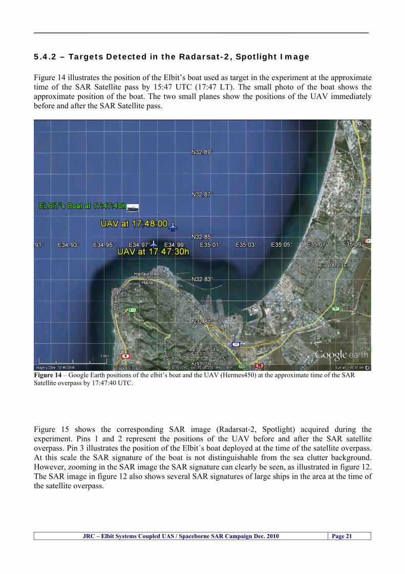
__________________________________________________________________________________
JRC ndash Elbit Systems Coupled UAS Spaceborne SAR Campaign Dec 2010 Page 21
542 ndash Targets Detected in the Radarsat-2 Spotlight Image Figure 14 illustrates the position of the Elbitrsquos boat used as target in the experiment at the approximate time of the SAR Satellite pass by 1547 UTC (1747 LT) The small photo of the boat shows the approximate position of the boat The two small planes show the positions of the UAV immediately before and after the SAR Satellite pass
Figure 14 ndash Google Earth positions of the elbitrsquos boat and the UAV (Hermes450) at the approximate time of the SAR Satellite overpass by 174740 UTC Figure 15 shows the corresponding SAR image (Radarsat-2 Spotlight) acquired during the experiment Pins 1 and 2 represent the positions of the UAV before and after the SAR satellite overpass Pin 3 illustrates the position of the Elbitacutes boat deployed at the time of the satellite overpass At this scale the SAR signature of the boat is not distinguishable from the sea clutter background However zooming in the SAR image the SAR signature can clearly be seen as illustrated in figure 12 The SAR image in figure 12 also shows several SAR signatures of large ships in the area at the time of the satellite overpass
__________________________________________________________________________________
JRC ndash Elbit Systems Coupled UAS Spaceborne SAR Campaign Dec 2010 Page 22
Elbit`s Boat
Figure 15 ndash On the background the SAR image with the two UAV positions before and after the satellite overpass (Pin1 and Pin2) and the Elbitacutes Boat position (Pin3) The small window over the SAR image shows a zoom in of the SAR image where the SAR signature of the Elbitacutes Boat can clearly be seen The top right are of the SAR image also shows SAR signatures of several large ships in the area at the time of the SAR satellite overpass Figure 16 shows the corresponding SAR image (Radarsat-2 Spotlight) acquired during the experiment and the UAV IR images of some of the targets Pins 1 and 2 represent the positions of the UAV before and after the SAR satellite overpass Pin 3 illustrates the position of the Elbitacutes boat deployed at the time of the satellite overpass At this scale the SAR signature of the boat is not distinguishable from the sea clutter background However zooming in the SAR image the SAR signature can clearly be seen as illustrated in figure 13 On the top left the UAV IR image of the Elbitrsquos Boat The SAR image in figure 13 also shows several SAR signatures of large ships in the area at the time of the satellite overpass On the centre left the UAV IR image of a large ship On the centre right the UAV IR image of a large ship On the bottom right the UAV IR image of a large ship All the UAV images were acquired at night in complete darkness from altitudes in the order of 5500 meters Nonetheless the quality and detail of the UAV images allows classification of the targets and in some cases the identification As it can be seen the potential of UAV for maritime surveillance is very promising During the experiment the UAV detected all the boats and ships in the area and tracked some of the boatsships to test the tracking capability The capability of detection and tracking targets is a critical capability for maritime surveillance
__________________________________________________________________________________
JRC ndash Elbit Systems Coupled UAS Spaceborne SAR Campaign Dec 2010 Page 23
Elbitacutes Boat
Elbit`s Boat
Figure 16 ndash Zoom-in of figure 15 with the UAV images of some targets On the top left the UAV IR image of the Elbitrsquos Boat On the centre left the UAV IR image of a large ship On the centre right the UAV IR image of a large ship On the bottom right the UAV IR image of a large ship Figure 17 shows a comparison of the SAR and UAV images with an optical photo taken in Haifa Israel a couple of hours before the SAR satellites overpass Most of the large ships were detected in the SAR image and some of these ships can be identified in the optical photo Some of the ships in the photo left the area before the SAR satellites overpass
__________________________________________________________________________________
JRC ndash Elbit Systems Coupled UAS Spaceborne SAR Campaign Dec 2010 Page 24
Figure 17 ndash Photo taken in Haifa Israel a couple of hours before the SAR satellites overpass This phot shows the large ships moored in the area Most of these large ships were detected in the Radarsat-2 image As expected their positions and orientations were slightly different at the time of the satellite overpass
Elbitacutes Boat
Elbit`s Boat
__________________________________________________________________________________
JRC ndash Elbit Systems Coupled UAS Spaceborne SAR Campaign Dec 2010 Page 25
Figure 18 ndash Photo taken in Haifa Israel a couple of hours before the SAR satellites overpass This phot shows the large ships moored in the area Most of these large ships were detected in the Radarsat-2 image As expected their positions and orientations were slightly different at the time of the satellite overpass Figure 18 illustrates the SAR image and the corresponding google earth image of a small pier in the port of Haifa In the SAR image due to several artefacts it is not possible to detect the 7 small boats moored to the small pier The UAR IR image of the same area clearly shows the 7 small boats with impressive detail taking into account that the image was acquired from an altitude of about 5500 meters A zoom in of the same UAV IR image is shown in figure 19 As it can be seen although the image was acquired from an altitude of about 5500 meters the 7 small boats can be clearly seen with enough detail to allow classification of the type of boat A UAV flight at lower altitude would probably giver a lot more detail and eventually allow the identification of the small boats
__________________________________________________________________________________
JRC ndash Elbit Systems Coupled UAS Spaceborne SAR Campaign Dec 2010 Page 26
Figure 19 ndash UAV IR image of a small pier in the port of Haifa Israel where 7 small boats can be seen with enough detail to allow classification This image was acquired from an altitude of about 5500 meters in the dark
__________________________________________________________________________________
55 ndash Quantitative Analysis of the Spaceborne SAR Image In order to allow a quantitative analysis of the data the spaceborne SAR image was calibrated using ESArsquos NEST software package version 4B The input was the SAR image acquired and the output was the Radiometric Calibration (Sigma Naught (σdeg)) expressed in terms of intensity and in decibel (dB) the Radar Brightness (βdeg) and the Radiometric Normalisation (gamma naught (γdeg))
551 ndash Radarsat-2-Spotlight 08Dec2010 (154740 UTC) Haifa Israel Figure 20 illustrates the Intensity band of a subset of the Radarsat-2Spotlgiht image (08Dec2010)
Figure 20 ndash Radarsat-2 Spotlgiht image (08Dec2010) ndash Sigma Naught (Intensity) band
JRC ndash Elbit Systems Coupled UAS Spaceborne SAR Campaign Dec 2010 Page 27
__________________________________________________________________________________
Figure 21 illustrates the Sigma Naught Coefficient of the Radarsat-2 Spotlgiht image (08Dec2010) expressed in terms of intensity and decibel (dB)
Figure 21 ndash Radarsat-2 Spotlgiht image (08Dec2010) - On the left the Sigma Naught (σdeg) (intensity) and on the right the Sigma Naught (σdeg) (dB)
ormalisation amma Naught (γdeg)) of the Radarsat-2 Spotlgiht image (08Dec2010) expressed in dB
-2 Spotlgiht image (08Dec2010) - On the left the Beta Naught (βdeg) and on the right the Gamma Naught (γdeg) (dB)
Figure 22 illustrates the Radar Brightness (Beta Naught (βdeg)) and the radiometric n(G
Figure 22 ndash Radarsat
JRC ndash Elbit Systems Coupled UAS Spaceborne SAR Campaign Dec 2010 Page 28
__________________________________________________________________________________ Figure 23 shows the Sigma Naught (σdeg) in dB after some colour manipulation and the histogram of the Sigma Naught (σdeg) image
Figure 23 ndash Radarsat-2 Spotlgiht image (08Dec2010) - On the top left the Sigma Naught (σdeg) after colour manipulation to enhance the targets and on the top right the corresponding histogram On the bottom we can see the histogram of the image
Table 6 gives the statistics of the Sigma Naught (σdeg) Radarsat-2 Spotlgiht image (08Dec2010) The Sigma Naught (σdeg) range from -72897 dB up to 23465 dB The Mean value is -16855 dB the Median is -16594 dB and the standard deviation is 7077 dB
JRC ndash Elbit Systems Coupled UAS Spaceborne SAR Campaign Dec 2010 Page 29
__________________________________________________________________________________
JRC ndash Elbit Systems Coupled UAS Spaceborne SAR Campaign Dec 2010 Page 30
Table 6 ndash Statistics of the Radarsat-2 Spotlgiht image (08Dec2010) (154740 UTC)
Statistics Values Unit Only ROI-Mask pixels considered Number of pixels total Number of considered pixels Ratio of considered pixels
No 322394283 322394283
1000
Minimum Maximum
-728974609375 234655818939209
intensity_db intensity_db
Mean Median Std-Dev Coefficient of Variation
-16855686580177853 -1659462338617847 707796800831575
07888765273432338
intensity_db intensity_db intensity_db intensity_db
Checking the radar backscattering coefficient of some targets (small boat and some large ships) detected in the Radarsat-2 Spotlight image we get values ranging from -0379 dB up to 23455 dB The analysis of the Sigma Naught values (σdeg) of the targets and the area around the targets shows a significant contrast
56 ndash Summary of the Preliminary Analysis of the Spaceborne SAR Image This experiment involved two spaceborne SAR images namely a TerraSAR-X Stripmap and one Radarsat-2 Spotlight The TerraSAR-X image was not delivered by DLR due to technical problems The Elbitrsquos boat deployed during the experiment was detected in the Radarsat-2 Spotlight image Several other targets including a set of large ships were also detected Table 7 summarises the characteristics of the SAR image acquired and the targets detected
Table 7 ndash List of SAR Satellite Images acquired during the experiment and detected boats ISRAEL (HAIFA)
Date Time Place Satellite Mode Ground Truth Data Detected Boats
08Dec2010 (PM) Haifa - Israel Radarsat-2 Spotlight GPSPhotosMovies 1 small boat deployed + 9 large ships
Table 8 gives the minimum and maximum Sigma Naught (σdeg) of the targets detected in each SAR image
Table 8 ndash Minimum and maximum Sigma Naught (σdeg) of the targets detected in each SAR image
Date Time UTC (LT)Pass Satellite Image Mode Polarisation Sigma Naught (σdeg) Min Max
29Oct2010528UTC(728AM LT) DES Radarsat-2 Spotlight HH --0379 dB 23455 dB The SAR signatures of the boats deployed were very weak Some possible reasons to explain such weak signatures are the sea state the wind speed the incidence angle and the type and materials Another possible reason is the processing at DLR
__________________________________________________________________________________
JRC ndash Elbit Systems Coupled UAS Spaceborne SAR Campaign Dec 2010 Page 31
6 ndash Preliminary Conclusions The analysis of the results of this coupled UASSpaceborne SAR experiment shows a promising potential for the use of UAS for maritime surveillance UAS can be integrated into the airborne building block of maritime surveillance systems to complement the existing assets increase system performance and improve the overall maritime domain awareness The main perceived maritime security and safety threats comprise piracy terrorist and military threats weapons proliferationsmuggling drugs trafficking illegal immigration unlawful use of containers attacks to critical infrastructures and illegal fishing The main maritime security and safety gaps include a lack of technologies with the capability of detecting small targets (eg small boats) a lack of wide area and persistent maritime surveillance a lack of coordination and information sharing limited interoperability a lack of containers security a lack of persistent surveillance of critical infrastructures and early warning systems Unmanned Aircraft Systems (UAS) are an emerging technology with strong potential to mitigate the above mentioned threats by filing in the main maritime security and safety gaps listed earlier For instance the wide range of potential applications of UAS to maritime surveillance includes but is not limited to
bull detection classification and identification of small boats bull persistent maritime surveillance bull use as communications relays bull persistent surveillance of critical infrastructures bull early warning systems bull COMINT and ELINT collection etc
Table 11 illustrates the mapping of maritime securitysafety threats vs gaps and summarises the main potential applications of UAS to maritime surveillance The above mentioned potential applications of UAS to the Maritime Domain will be addressed in turn in more detail next bull Detection classification and identification of small boats ndash The capability of detecting classifying and identifying small targets (eg small boats) is among the key technologies required to improve maritime domain awareness This capability is critical to mitigate piracy illegal immigration drugs trafficking weapons smuggling illegal fishing terrorism and critical infrastructure Unmanned Aircraft Systems (UAS) provide this capability more efficiently and at a lower cost than any other existing technology bull Persistent maritime surveillance ndash With the continuous improvements of UAS technologies such as platforms sensors collision avoidance systems command and control systems telecommunications etc UAS are increasing their autonomy endurance and flexibility These characteristics are very important for persistent maritime surveillance UAS can be launched from land ships aircraft and technologies to launch UAS from submarines are currently under development UAS have distinct advantages over other existing technologies for persistent maritime surveillance in terms of autonomyendurance (the Global Surveyor has an autonomy of 1 week) cost (eg as the autonomy of UAS increases the number of staff required to operate UAS decreases) risk (eg if the UAS crashes the crew is not at risk) flexibility (eg they can be launched from a ship reducing the time to reach potential threats) etc
__________________________________________________________________________________
JRC ndash Elbit Systems Coupled UAS Spaceborne SAR Campaign Dec 2010 Page 32
bull Communications relays ndash UAS are being used as communication relays mainly in military context but have the potential to play a similar role in Civil context in several situations such as to replace satellite communications or as a redundant system over any location on Earth The main advantages of using UAS as communication relays is that airborne communication relays mitigate kinetic and noise jamming threats to satellite communications uplinks by providing an alternative set of links either directly to surface-based terminals or to satellites beyond the range of threats They are less susceptible to noise jamming threats than satellites because an adversary has to detect geolocate and track the airborne asset and operate within line of sight of the receive antenna main beam bull Persistent surveillance of critical infrastructures ndash The security of critical infrastructures such as nuclear power plants refineries ports etc requires persistent surveillance UAS can play an important role in providing persistent surveillance over critical infrastructures and over a wide area around the critical infrastructure Some advantages of UAS over other existing technologies such as ground-based assets (eg video cameras alarm systems manned aircraft etc) comprise the security of the UAS (eg hardly can be damaged or switched off as any ground-based asset) the area covered by a UAS (eg it is larger than the area covered by any ground-based asset) the cost (eg UAS is cheaper than manned aircraft with similar capability) etc bull Early warning systems ndash UAS have the potential to be used as part of an integrated system of systems for early warning A UAS can provide information about a given area at a fraction of the cost of alternative means Formation flying of UAS can cover a wide maritime area It is reasonable to assume that in a foreseeable future with the advent of UAS with increased autonomy the operations cost of UAS will likely decrease making them increasingly more attractive bull COMINT and ELINT collection ndash SIGNal INTelligence (SIGNINT) can be divided into two categories namely COMINT and ELINT COMINT stands for Communication Intelligence and ELINT for Electronic Intelligence Collection of COMINT is passive Exploitation of COMINT requires a human operator which implies COMINT UAS are suitable for COMINT and ELINT collection in different scenarios The relatively reduced amount of data collected and analysed during this experiment and the lessons learned do not allow drawing final conclusions about the feasibility of using Unmanned Aerial Systems (UAS) for maritime surveillance However this experiment allowed hands-on experience with UAS technologies and significantly improved the awareness for its applications to maritime surveillance and related issues involved including its potential the feasibility as well as the limiting and enabling factors These different aspects will now be analysed in turn in the next sections Table 11 illustrates the mapping of the main maritime security threats and gaps as well as the main priorities in terms of the different technologies involved in maritime surveillance For each maritime threat the technologies required to fill in each gap is indicated and its priority is expressed in a range of numbers (1 to 3 1 = Maximum Priority 2 = Medium Priority 3 = Low Priority) and colours (Red = Maximum Priority Orange = Medium Priority Green = Low Priority) The main technologies involved in maritime surveillance are listed on the bottom of figure 4 and are reproduced here for convenience of the reader 1- Reporting Systems 2- Sensors 3- Platforms 4- Communications 5- Data Fusion amp Sharing 6- Intelligence and 7- Databases For example the mitigation of the main threat Piracy requires filling in several maritime security gaps (eg lack of persistent surveillance lack of wide-are maritime surveillance lack of small boat detection lack of Early Warning Systems and lack of Information Sharing with maximum priority (1- Red) and among the required technologies listed are UAS LTAAV GEO-HR etc Concerning the remaining two gaps (Limited Interoperability and Containers Security) they are less relevant to mitigate Piracy hence the priority for Limited Interoperability is 2-Orange and for Containers Security is 3- Green
__________________________________________________________________________________ Table 9 ndash The Main Maritime Security and Safety Threats vs Gaps and the technologies that can be used to mitigate them
Maritime Security Main Threats GapsGapsrarr
darrThreats
Lack o f Risk As sessmentCapab ility
La ck of Persiste nt
Surveilla nce
La ck of Wid e-Area su rve illanc e
La ck of Small Boat De tecti on
Lack o f Earl y Warn ing Sys tems
L ack of In forma tion
Sh arin g
L imi ted In terop era bility
Lac k of Co ntai ners
Se cur ity
bull PiracyUAS LTAVG EO-
HR + UAS LT AVGEO-
HR + SAR GEO-HR
+ UAS USV LTAV
+ UAS LTAV
+ Coord in ationamp Sharing +
Inter opera bilityOptimisation +
1 2 3 5 6 7 1 2 3 5 6 7 1 2 3 5 6 1 2 3 123456 4567 1234567 1234567
bull Terro rismUAS LTAVG EO-
HR + UAS L TAV GEO-HR +
SAR AISGEO-HR +
UAS USV LTAV+
Intelligence+
Inte lligen ce+
Inter opera bilityOptimisation +
Intelligence+
1 2 3 5 6 7 1 2 3 5 6 1 2 3 5 6 1 2 3 123456 4567 1234567 1234567
bull Wea pon s ofM ass Dest ru ctio n Smugg ling
UAS LTAVG EO-HR +
UAS LT AVGEO-HR +
SAR AIS+
UAS USV LTAV+
Intelligence+
Inte lligen ce+
Intelligence+
Intelligence+
1 2 3 5 6 7 1 2 3 5 6 1 2 3 5 6 1 2 3 123456 4567 1234567 1234567
bull Drug sTraffic king
UAS LTAVG EO-HR +
UAS LT AVGEO-HR +
SAR AIS+
UAS USV LTAV+
Intelligence+
Inte lligen ce+
Intelligence+
Intelligence+
1 2 3 5 6 7 1 2 3 5 6 1 2 3 5 6 1 2 3 123456 4567 1234567 1234567
bull Illega lImmigratio n
UAS LTAVG EO-HR +
UAS LT AVGEO-HR +
SAR AIS+
UAS USV LTAV+
Intelligence+
Inte lligen ce+
Intelligence+
Intelligence+
1 2 3 5 6 7 1 2 3 5 6 1 2 3 5 6 1 2 3 123456 4567 1234567 1234567
bull Critic alI nfrastruc tureSecu rit y
UAS LTAVG EO-HR +
UAS LT AVGEO-HR +
SAR AIS+
UAS USV LTAV+ + Inte lligen ce
+ Intelligence
+ Intelligence
+
1 2 3 5 6 7 1 2 3 6 1 2 3 5 6 1 2 3 123456 4567 1234567 1234567
bull Illega lFish ing
UAS LTAVG EO-HR +
AI S+SAR UASLTAV +
SAR AIS GEO-HR+
UAS USV LTAV+
Intelligence+
Inte lligen ce+
Intelligence+
1 2 3 5 6 7 1 2 3 5 7 1 2 3 5 6 1 2 3 123456 4567 1234567
bull Un lawf ul Use of Co nta iners
(Secur ity)
UAS LTAVG EO-HR +
GPS Tr acking+
Intelligence+
Inte lligen ce+
GPS Int rusion Det ection Se al
1 2 3 5 6 7 4 6 7 1 2 3 5 6 1 2 3 123456 4567 1234567 1234567
(-) Priority (+) Not Rel evant
SURVEILLANCETECHNOLOGIES
1- Reporti ng Systems
2 -Sensors 3 -P latforms 4 - Communications 5- Data Fusionamp Sharing
6 -I ntelli gence 7 -Databases
JRC ndash Elbit Systems Coupled UAS Spaceborne SAR Campaign Dec 2010 Page 33
__________________________________________________________________________________
JRC ndash Elbit Systems Coupled UAS Spaceborne SAR Campaign Dec 2010 Page 34
61 ndash Hands-on experience with UAS technologies and its applications to maritime surveillance This coupled UASSpaceborne SAR campaign was a unique opportunity to acquire further handsndashon experience with UAS technologies and learn about the main issues related to its applications to maritime surveillance From the planning phase up to the execution of the UAS flight and landing there are several factors that need to be carefully analysed and taken into account A summary of the main issues identified in this experiment is given next 1- Selection of the Experiment Area Authorisation to Fly ndash For the time being UAS can only be flown in restricted areas usually under control of national authorities often the military This is due to the risks that a UAS can pose to human life and property In the present case an area under the authority of the Israeli Civil Aviation Authority was selected The authorisation to fly was not easy to obtain because the selected area is under the authority of the Civil Aviation Authority Figure 24 indicates the area of the experiment in Haifa Israel 2- UAS Communications Issues ndash The Hermes 450 was flown in Line-of-Sight (LOS) since it was close to the coast For BLOS (Beyond Line-of-Sight) operation satellite communications are required 3- Synthetic Aperture Radar (SAR) ndash The specific model Hermes 450W used in the experiment had no SAR sensor installed However a SAR sensor can be installed A SAR sensor is important for maritime surveillance since it allows 247 operations regardless of the weather conditions 4- Automatic Identification System (AIS) Receiver ndash The Hermes 450 used in this experiment was not equipped with an AIS receiver For maritime surveillance operations an AIS receiver is a very important tool since it allows the automatic identification of most ships allowing the UAS to concentrate on non-identified ships
__________________________________________________________________________________
Figure 24 ndash The area of the experiment is indicated by the GPS Trajectory of the UAV
62 ndash Potential of UAS for Maritime Surveillance UAS technologies are relatively recent and involve a wide range of fields spanning from aeronautics and sensors technologies to satellite communications and other engineering disciplines Innovations in each of the fields involved are emerging by the day UAS still have a long way to go before they become mature and their use fully operational For the time being UAS are mainly used for military applications However a large number of non-military UAS applications have been identified by stakeholders and there are several studies and demonstration flights foreseen for the near future Maritime surveillance is one of the most challenging and promising fields of application of UAS The challenges are due to the very demanding conditions under which the UAS must operate over sea and the requirements for safe operation
JRC ndash Elbit Systems Coupled UAS Spaceborne SAR Campaign Dec 2010 Page 35
__________________________________________________________________________________
JRC ndash Elbit Systems Coupled UAS Spaceborne SAR Campaign Dec 2010 Page 36
The present UAS experiment has unveiled some of the potential of UAS for maritime surveillance The UAS tests performed during this experiment include
1 ndash Detection of a Small rubber Boat and a Fishing Ship 2 ndash Tracking of a Small Boat and a Fishing Ship 3 ndash Classification of a Small Boat and a Fishing Ship 4 ndash Identification of a Small Boat and a Fishing Ship 5 ndash Detection and Tracking of People on the Beach
Despite the operational requirement that prevented the UAS from flying bellow 3km the experiment has confirmed the capability of UAS for small boat detection tracking and classification as well as the capability for people detection and tracking Concerning the identification of the targets the characteristics of the images acquired during this mission suggest that flying at lower altitudes the UAS images would allow the identification of the targets The UAS images can be seen from Figure 15 to 20
621 ndash Advantages of UAS for maritime Surveillance Some of the advantages of using UAS for maritime surveillance have been described in the literature and are summarized bellow
1- One potential benefit of UAS is that they could fill in a gap in current maritime surveillance by improving coverage
2- The range of UAS is a significant asset when compared to border agents on patrol or stationary surveillance equipment
3- Eletro-Optical InfraRed (EOIR) sensors (cameras) can identify small size objects from very high altitudes (high resolution)
4- UAS can provide precise and near-real-time imagery to a ground control operator who would then disseminate that information so that informed decisions regarding the deployment of border patrol agents can be made quickly
5- Long endurance UAS used along the border can fly for more than 30 hours up to several days without having to refuel compared with manned helicopterrsquos average flight time of just over 2 hours
6- The ability of UAS to loiter for prolonged periods of time has important operational advantages over manned aircraft
7- The longer flight times of UAS means that sustained coverage over a previously exposed area may improve maritime security
8- The range of UAVs is a significant asset when compared to border agents on patrol or stationary surveillance equipment Nevertheless the extended range and endurance of UAVs may lessen the burdens on human resources at the borders
9- UAS accidents do not risk the lives of pilots as do the helicopters and aircraft currently used by Coast Guards for border patrolling
__________________________________________________________________________________
JRC ndash Elbit Systems Coupled UAS Spaceborne SAR Campaign Dec 2010 Page 37
622 ndash Possible Drawbacks of using UAS for maritime Surveillance UAS also have disadvantages some of them are briefly described next
1- There have been concerns regarding the high accident rate of UAS which can be multiple times higher than that of manned aircraft Because UAS technology is still evolving there is less redundancy built into the operating system of UAS than of manned aircraft and until redundant systems are perfected mishap rates are expected to remain high
2- If control systems fail in a manned aircraft a well-trained pilot is better positioned to find the source of the problem because of hisher physical proximity If a UAS encountered a similar system failure or if a UAS landing was attempted during difficult weather conditions the ground control pilot would be at a disadvantage because he or she is removed from the event Unlike a manned pilot the remote pilot would not be able to assess important sensory information such as wind speed
3- Inclement weather conditions can also impinge on a UAS surveillance capability especially UAS equipped with only an EO camera and Forward Looking Infrared Radar (FLIR) because cloudy conditions and high humidity climates can distort the imagery produced by EO and FLIR equipment The effects of extreme climatic or atmospheric conditions on sensors reportedly can be mitigated with the outfit of one synthetic aperture radar (SAR) system and a moving target indicator (MTI) radar However adding SAR and MTI to a UAS platform would increase the costs associated with using UAS
4- Depending on the type of UAS the costs of operating a UAS can be higher than the costs of operating a manned aircraft This is because some types of UAS require a significant amount of logistical support and specialized operator and maintenance training Operating one UAS may require a crew of up to 20 support personnel The high comparative costs of operating some sophisticated types of UAS may be offset somewhat by their comparatively lower unit costs
63 ndash Main Limiting Factors Preventing the Use of UAS Several pre-requisites must be satisfied to render the UAS a viable cost-effective and regulated alternative to existing resources Major civil and commercial market barriers include
Single European Sky Sense and Avoid technologies Command and Control Technologies Reliability Communications (Bandwidth LOS BLOS)
Lack of airspace regulation that covers all types of UAV systems (encompassing lsquosense and avoidrsquo airspace integration and airworthiness issues)
Affordability - price and customization issues (eg commercial off-the-shelf open modular architecture) Lack of efforts to establish joint customer requirements (although this is gradually changing) Liability for civil operation Capacity for payload flexibility Lack of sufficient secure non-military frequencies for civil operation Perceived reliability (eg vehicle attrition rate vs manned aircraft) Operator training issues Recognitioncustomer perception of the UAV market Technology developments for multi-mission capability
__________________________________________________________________________________
64 ndash UAS Key Enabling Technologies Figure 25 illustrates the components of a typical UAV System showing some of the capabilities needed and the enabling technologies required for performing a given mission Any UAV mission involves many capabilities and technologies Due to the depicted system complexity the main key players such as the US Department of Defense (DoD) and other agencies have started to use the term Unmanned Aerial System (UAS) in place of UAV
Figure 25 ndash Unmanned Aerial Vehicle System Enabled by Autonomous Mission Management Reliable Flight Systems Navigation Accurate Systems Terrain Avoidance Power and Propulsion Some UAS key enabling technologies are listed below
Autonomous Mission Management Collision Avoidance Intelligent System Health Monitoring
Reliable Flight Systems Sophisticated Contingency Management Intelligent Data Handling and Processing Over-the-Horizon Communication Network-Centric Communication Open Architecture Power and Propulsion Navigation Accurate System Technology Enhanced Structures
JRC ndash Elbit Systems Coupled UAS Spaceborne SAR Campaign Dec 2010 Page 38
__________________________________________________________________________________
JRC ndash Elbit Systems Coupled UAS Spaceborne SAR Campaign Dec 2010 Page 39
Table 12 gives a more detailed description of other critical technologies for emerging autonomous UAV systems both civil and military Most of the technologies mentioned in Table 12 apply both to civil and military UAV systems Table 10 ndash Key Enabling Technologies (from SG75 study on autonomous systems)
Critical Technologies Decision Making Software
bull Fuzzy-based decision making bull Knowledge-based system bull Case-based reasoning bull Self-learning techniques bull Decision tree evaluation bull ReasoningInferring bull Probabilisticstochastic reasoning
Prediction Algorithms bull Predictive pathintent algorithms bull Short reaction algorithm bull Effectiveness evaluation
Status Assessment Software bull Internal status analysis bull Self-orientation
Situation Analysis Software bull Situation analysis bull Environmental analysis bull External status analysis
Modelling Software bull Air vehicle modelling algorithms bull Sensor modelling algorithms bull Scenario generation bull Threat system modeling bull Attack simulation bull Mission success optimisation model bull Simulation
Sensor Processing Software bull Sensor fusion bull Area of interest identification bull Automatic target recognition
Adaptive and Self-learning Systems bull Failure self-compensation
Attack Planning Software bull Attack plans and tactical alternatives bull Plan change impact identification
Weapon Engagement Procedure Software bull Weapon engagement algorithms
Mission Plan Update Software bull Route planning system bull Payload plan management system bull Mission Success Optimisation model
Path Optimisation Software bull Optimal trajectory planning bull Path Optimisation System
Targeting Software bull Target tracking bull Target prioritisation
Platform Technologies bull Obstacle detection and avoidance (airborne) bull Obstacle detection and avoidance (ground) bull Improved autopilot bull Speech recognition
Figure 26 summarises system element designs needed to transition from current to next-generation autonomous UAV systems for civilian and military UAS
__________________________________________________________________________________
Figure 26 ndash System Element Designs Needed to Transition from Current to Next-Generation Autonomous UAV Systems These new paradigms are a combination of system attributes and technological capabilities For instance the data fusion secure anti-jam and coordinated multi-vehicle control require technological development as well as specific system development to bring full maturity to unmanned systems Finally very small Micro UAVs (MAVs) and relatively large sophisticated UCAV systems are examples of the range of UAVs that are applying the new platforms payloads onboard processing communications etc to create next generation automated UAVs It is with these new platforms payloads etc that both UCAVs and MAV will be able to address similar operational challenges including
Mixed operation with other assets bull Deconfliction collision avoidance C4I integration
Operation over populated areas bull Safety issues Need to reduce reliance on communications bull UCAV ndash countermeasures bull MAV ndash limited size and power bull Limited line of sight environment Need a fully integrated system bull MAV propulsionpower generation still critical bull Operator machine interface critical bull All weather operations bull Survivability
JRC ndash Elbit Systems Coupled UAS Spaceborne SAR Campaign Dec 2010 Page 40
__________________________________________________________________________________
JRC ndash Elbit Systems Coupled UAS Spaceborne SAR Campaign Dec 2010 Page 41
65 ndash Mission Readiness
651 ndash Mission Readiness Summary This section summarises civil UAV mission readiness The purpose of Mission Readiness is to assess the readiness status of the different technologies involved in UAS In the present case this civil UAV mission readiness based on technology maturation forecasts that meet or exceed the desired or required capabilities identified by the user community Figure 27 summarises the mission readiness time forecasts for the different technologies The technologies annotated with an asterisk () are shown within the figure with maturation forecasts based on development targets expressed in the US Department of Defencesrsquo UAV Roadmap document The purpose of the chart is to be able to identify when the capability to fly a particular mission can be expected as a function of time The left-most end is the least probable and the right end the most probable timeframe
Figure 27 ndash Technology Maturation Summaries in Terms of Mission-Derived Capabilities
__________________________________________________________________________________
JRC ndash Elbit Systems Coupled UAS Spaceborne SAR Campaign Dec 2010 Page 42
66 ndash Small Boat Detection in SAR Satellite Imagery The use of spaceborne SAR imagery for small boat detection requires additional small boat detection experiments under different conditions using different methods It is not possible to draw final conclusions based on a limited number of small boat detection experiments which are not representative of the multiple possible scenarios
67 ndash Limitations of current State-of-the-Art SAR Satellite technology The main limitations of current State-of-the-Art spaceborne SAR imagery for maritime surveillance in particular aimed at small boat detection are 1 - SAR satellites repeat cycles do not allow the coverage of the same area at the required time intervals Constellations of SAR satellites could be a solution 2 - The conflict between resolution and image swath High resolution is required to detect small boats However the high resolution images have small swaths Maritime surveillance with high resolution images would require a large number of images to cover wide maritime areas which is very expensive and for the time being technically not feasible Intelligence data can play an important role by indicating an approximate position of suspicious non cooperative targets therefore reducing the surveillance area which can then be imaged using high resolution images 3- Spaceborne high resolution SAR imagery acquisition times are long enough to allow significant motion of the target during the acquisition time degrading the quality of the image Further research efforts are needed to develop new sensors and platforms As far as sensors are concerned shorter integration times are needed to prevent the blurring effect caused by the motion of the targets Regarding the platforms more platforms are needed to allow lower repeat cycles and improved coverage
__________________________________________________________________________________
JRC ndash Elbit Systems Coupled UAS Spaceborne SAR Campaign Dec 2010 Page 43
7 ndash Plans for Future Work The controlled experiments carried out by the EC-JRC together with Elbit Systems in Haifa-Israel comprised the deployment of a UAS (Hermes-450) and one small 12-meter boat A Radarsat-2 Spotlight image was acquired and several images collected by the Hermes-450 The experiment unveiled the potential of UAS for maritime surveillance in particular for detection tracking classification and possible identification of small targets The UAS was able to detect track and classify small targets such as small boats For low UAS altitude flights identification may be possible in some cases The small 12-meter boat was detected in the spaceborne SAR image The small boat detection trials carried out by the JRC were very successful since most small boats deployed during the experiments were detected in different sea states wind speeds and geographical locations The several small boat detection campaigns conducted by the EC-JRC seem to suggest that the probability of detection of small boats in spaceborne SAR images strongly depends on factors such as the sea state the wind speed the type of boat (shape and materials) the weather conditions among other factors The results of the experiments conducted thus far are not enough to draw final conclusions about the feasibility of using spaceborne SAR imagery for small boat detection However the experiments have an overall positive outcome because they indicate that under suitable sea state and wind speed conditions it is possible to detect small boats using spaceborne SAR The estimation of the probability of detection of small boats in spaceborne SAR images requires a large number of experiments under different circumstances (eg sea state wind speed characteristics of the targets image type and mode etc) Future plans include additional UAS experiments to asses its potential for maritime surveillance
Acknowledgements ndash The authors would like to express their gratitude to Elbit Systems for their cooperation logistical support and assets deployed without which the present coupled UASSAR Satellite Small Boat Detection Campaign would have not been possible
__________________________________________________________________________________
JRC ndash Elbit Systems Coupled UAS Spaceborne SAR Campaign Dec 2010 Page 44
REFERENCES [1] Elbit Systems ldquoUAV Elbit Systems Proposal for Unmanned Aerial Vehicle (UAV) flight to
collect Ground Truth data during a Maritime Surveillance Campaign and demonstrate UAV capabilities for Maritime Surveillancerdquo 2010
[2] ndash Cheryl Yuhas Suborbital Science Program Manager NASA Science Mission Directorate ldquoEarth Observations and the Role of UAVs A Capabilities Assessment Version 11rdquo Civil UAV Assessment Team httpwwwnasagovcentersdrydenresearchcivuavindexhtml August 2006
[3] ndash Document NIAG (SG75) NATO Industrial Advisory Group Study Group 75 Pre-Feasibility Study on UAV Autonomous Operations 2004
[4] ndash United States Department of Defence (DoD) Directive 50001 ldquoThe Defense Acquisition Systemrdquo and DoD Instruction 50002 ldquoOperation of the Defense Acquisition Systemrdquo
[5] ndash Mr James Ramage Mr Massimo Avalle Dr Erik Berglund Dr Luigi Crovella Mr Robert Frampton Dr Uwe Krogmann Mr Christian Ravat Mr Mike Robinson Dr Axel Schulte Dr Scott Wood ldquoRTO-TR-SCI-118 - Automation Technologies and Application Considerations for Highly Integrated Mission Systemsrdquo RTO-TR-SCI-118 AC323(SCI-118)TP204 January 2009
[6] Victor MG Silva Gilles Jurquet Gabriel Marchalot Maria TG Calzado Txema Soroa Juan Sancho Adam Koubek Harm Greidanus and Claudio Savarino ldquoWide Maritime Area Airborne Surveillance (WIMA2S) WP5 Final Reportrdquo WIMAAS WP5 FP7 Project 2008-2011 - ISBN-978-92-79-22801-8 (print) 978-92-79-22802-5 (PDF) ISSN-1018-5593 (print) 1831-9424 (online) EC-JRC Scientific Report JRC 70093 2012
[7] Victor MG Silva and Harm Greidanus ldquoSpaceborne SAR Small Boat Detection Campaign in Portugal and Spainrdquo EUR 25281 EN ISBN 978-92-79-22553-6 ISSN 1831-9424 (online) EC-JRC Scientific Report JRC68160 2012
[8] Goncalves Da Silva V Van Wimersma Greidanus H Hejmanowska B Loudjani P ldquoUAS Applications With Societal Benefits ndash JRCrsquos UAS-Related Activitiesrdquo 2011-2012 UAS Yearbook - UAS Unmanned Aircraft Systems - The Global Perspective 9 (9) 2011 p 127-129 JRC66600
[9] Goncalves Da Silva V Van Wimersma Greidanus H ldquoSmall boat detection using TerraSAR-X and Radarsat2 satellite imageryrdquo 4th TerraSAR-X Science Team Meeting 14 February 2011 DLR Oberpfaffenhofen (Germany) German Aerospace Center (DLR) (Organiser) 2011 JRC63663
[10] V Silva Harm Greidanus ldquoJRC - SAR Satellite Small Boat Detection Campaign - Portoroz ndash Sloveniardquo - ISBN-13 978-92-79-21476-9 ISSN (online) 1831-9424 EC-JRC Scientific Report JRC66835 2011
[11] V Silva Harm Greidanus ldquoJRC - SAR satellite small boat detection campaign - Algarve Portugalrdquo - ISBN-13 978-92-79-21265-9 ISSN (online) 1831-9424 ISSN (print) 1018-5593 EC-JRC Scientific Report JRC66631 2011
[12] ndash Goncalves Da Silva V Van Wimersma Greidanus H ldquoJRC-Frontex Spaceborne SAR Small Boat Detection Campaign ndash Italy amp Spainrdquo - ISBN-13 978-92-79-22213-9 ISSN (online) 1831-9424 EC-JRC Scientific Report JRC67517 2011
[13] - PW Vachon SJ Thomas J Cranton HR Edel and MD Henschel Validation of ship detection by the RADARSAT synthetic aperture radar and the Ocean Monitoring Workstation Canadian Journal of Remote Sensing 26(3)200ndash212 2000
[14] - Crisp D (2004) The state-of-the-art in ship detection in Synthetic Aperture Radar imagery DSTO Information Sciences Laboratory Australia
[15] - Joint Research Centre (JRC) of the European Community mdash IMPAST and DECLIMS web site httpintelligencejrcceceuintmarinefishindexhtm
[16] - McCandless SW Jackson CR (2004) Principles of Synthetic Aperture Radar Synthetic Aperture Radar Marine Users Manual NOAA Washington pp 1-23
[17] - Greidanus H (2008) Satellite Imaging for Maritime Surveillance of the European Seas Remote Sensing of the European Seas 343-358
European Commission
EUR 25346 EN --- Joint Research Centre --- Institute for the Protection and Security of the Citizen
Title JRC --- Elbit Systems Coupled UAS and Spaceborne SAR Campaign in Israel
Authors Victor MG Silva Harm Greidanus
Luxembourg Publications Office of the European Union
2012 --- v+44 pp --- 210 x 297 cm
EUR --- Scientific and Technical Research series --- ISSN 181-9424 (online) ISSN 1018-5593 (print)
ISBN 978-92-79-25020-0
doi10278828527
Abstract The European maritime area is one of Europersquos most important assets with regard to resources security and ultimately
prosperity of the Member States A significant part of Europersquos economy relies directly or indirectly on it It is not just the
shipping or fisheries industries and their related activities It is also shipbuilding and ports marine equipment and offshore
energy maritime and coastal tourism aquaculture submarine telecommunications blue biotech and the protection of the
marine environment The European maritime area faces several risks and threats posed by unlawful activities such as drugs
trafficking smuggling illegal immigration organised crime and terrorism Piracy in international waters also constitutes a threat
to Europe since it can disrupt the maritime transport chain These risks and threats can endanger human lives marine resources
and the environment as well as significantly disrupt the transport chain and global and local security It is anticipated that these
risks and threats will endure in the mid and long run In order to keep Europe as a world leader in the global maritime economy
an effective integratedinteroperable sustainable maritime surveillance system and situational awareness are needed
A significant number of unlawful maritime activities such as illegal immigration drugs trafficking smuggling piracy and
terrorism involve mainly small boats because small boats are faster and more difficult to detect using conventional means
Hence it is very important to find out the feasibility of using Unmanned Aerial Systems (UAS) for small boat detection tracking
classification and identification as well as to study the potential of UAS for maritime surveillance Since 2010 the EC-JRC has
carried out a number of UAS maritime surveillance campaigns to study the potential of UAS for maritime surveillance in
particular for small boat detection This report presents the results and conclusions of the JRC --- Elbit Systems Coupled UAS and
Spaceborne SAR campaign carried out in Dec 2010 in Haifa Israel
As the Commissionrsquos in-house science service the Joint Research Centrersquos mission is to provide EU policies with independent evidence-based scientific and technical support throughout the whole policy cycle Working in close cooperation with policy Directorates-General the JRC addresses key societal challenges while stimulating innovation through developing new standards methods and tools and sharing and transferring its know-how to the Member States and international community Key policy areas include environment and climate change energy and transport agriculture and food security health and consumer protection information society and digital agenda safety and security including nuclear all supported through a cross-cutting and multi-disciplinary approach
LB-NA-25346-EN
-N
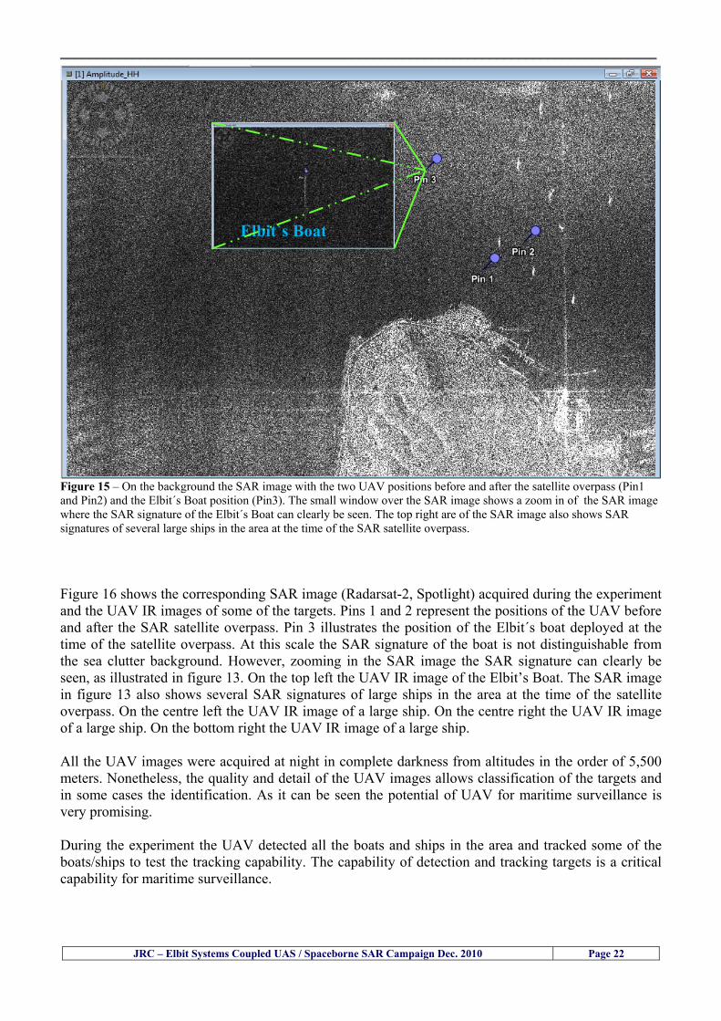
__________________________________________________________________________________
JRC ndash Elbit Systems Coupled UAS Spaceborne SAR Campaign Dec 2010 Page 22
Elbit`s Boat
Figure 15 ndash On the background the SAR image with the two UAV positions before and after the satellite overpass (Pin1 and Pin2) and the Elbitacutes Boat position (Pin3) The small window over the SAR image shows a zoom in of the SAR image where the SAR signature of the Elbitacutes Boat can clearly be seen The top right are of the SAR image also shows SAR signatures of several large ships in the area at the time of the SAR satellite overpass Figure 16 shows the corresponding SAR image (Radarsat-2 Spotlight) acquired during the experiment and the UAV IR images of some of the targets Pins 1 and 2 represent the positions of the UAV before and after the SAR satellite overpass Pin 3 illustrates the position of the Elbitacutes boat deployed at the time of the satellite overpass At this scale the SAR signature of the boat is not distinguishable from the sea clutter background However zooming in the SAR image the SAR signature can clearly be seen as illustrated in figure 13 On the top left the UAV IR image of the Elbitrsquos Boat The SAR image in figure 13 also shows several SAR signatures of large ships in the area at the time of the satellite overpass On the centre left the UAV IR image of a large ship On the centre right the UAV IR image of a large ship On the bottom right the UAV IR image of a large ship All the UAV images were acquired at night in complete darkness from altitudes in the order of 5500 meters Nonetheless the quality and detail of the UAV images allows classification of the targets and in some cases the identification As it can be seen the potential of UAV for maritime surveillance is very promising During the experiment the UAV detected all the boats and ships in the area and tracked some of the boatsships to test the tracking capability The capability of detection and tracking targets is a critical capability for maritime surveillance
__________________________________________________________________________________
JRC ndash Elbit Systems Coupled UAS Spaceborne SAR Campaign Dec 2010 Page 23
Elbitacutes Boat
Elbit`s Boat
Figure 16 ndash Zoom-in of figure 15 with the UAV images of some targets On the top left the UAV IR image of the Elbitrsquos Boat On the centre left the UAV IR image of a large ship On the centre right the UAV IR image of a large ship On the bottom right the UAV IR image of a large ship Figure 17 shows a comparison of the SAR and UAV images with an optical photo taken in Haifa Israel a couple of hours before the SAR satellites overpass Most of the large ships were detected in the SAR image and some of these ships can be identified in the optical photo Some of the ships in the photo left the area before the SAR satellites overpass
__________________________________________________________________________________
JRC ndash Elbit Systems Coupled UAS Spaceborne SAR Campaign Dec 2010 Page 24
Figure 17 ndash Photo taken in Haifa Israel a couple of hours before the SAR satellites overpass This phot shows the large ships moored in the area Most of these large ships were detected in the Radarsat-2 image As expected their positions and orientations were slightly different at the time of the satellite overpass
Elbitacutes Boat
Elbit`s Boat
__________________________________________________________________________________
JRC ndash Elbit Systems Coupled UAS Spaceborne SAR Campaign Dec 2010 Page 25
Figure 18 ndash Photo taken in Haifa Israel a couple of hours before the SAR satellites overpass This phot shows the large ships moored in the area Most of these large ships were detected in the Radarsat-2 image As expected their positions and orientations were slightly different at the time of the satellite overpass Figure 18 illustrates the SAR image and the corresponding google earth image of a small pier in the port of Haifa In the SAR image due to several artefacts it is not possible to detect the 7 small boats moored to the small pier The UAR IR image of the same area clearly shows the 7 small boats with impressive detail taking into account that the image was acquired from an altitude of about 5500 meters A zoom in of the same UAV IR image is shown in figure 19 As it can be seen although the image was acquired from an altitude of about 5500 meters the 7 small boats can be clearly seen with enough detail to allow classification of the type of boat A UAV flight at lower altitude would probably giver a lot more detail and eventually allow the identification of the small boats
__________________________________________________________________________________
JRC ndash Elbit Systems Coupled UAS Spaceborne SAR Campaign Dec 2010 Page 26
Figure 19 ndash UAV IR image of a small pier in the port of Haifa Israel where 7 small boats can be seen with enough detail to allow classification This image was acquired from an altitude of about 5500 meters in the dark
__________________________________________________________________________________
55 ndash Quantitative Analysis of the Spaceborne SAR Image In order to allow a quantitative analysis of the data the spaceborne SAR image was calibrated using ESArsquos NEST software package version 4B The input was the SAR image acquired and the output was the Radiometric Calibration (Sigma Naught (σdeg)) expressed in terms of intensity and in decibel (dB) the Radar Brightness (βdeg) and the Radiometric Normalisation (gamma naught (γdeg))
551 ndash Radarsat-2-Spotlight 08Dec2010 (154740 UTC) Haifa Israel Figure 20 illustrates the Intensity band of a subset of the Radarsat-2Spotlgiht image (08Dec2010)
Figure 20 ndash Radarsat-2 Spotlgiht image (08Dec2010) ndash Sigma Naught (Intensity) band
JRC ndash Elbit Systems Coupled UAS Spaceborne SAR Campaign Dec 2010 Page 27
__________________________________________________________________________________
Figure 21 illustrates the Sigma Naught Coefficient of the Radarsat-2 Spotlgiht image (08Dec2010) expressed in terms of intensity and decibel (dB)
Figure 21 ndash Radarsat-2 Spotlgiht image (08Dec2010) - On the left the Sigma Naught (σdeg) (intensity) and on the right the Sigma Naught (σdeg) (dB)
ormalisation amma Naught (γdeg)) of the Radarsat-2 Spotlgiht image (08Dec2010) expressed in dB
-2 Spotlgiht image (08Dec2010) - On the left the Beta Naught (βdeg) and on the right the Gamma Naught (γdeg) (dB)
Figure 22 illustrates the Radar Brightness (Beta Naught (βdeg)) and the radiometric n(G
Figure 22 ndash Radarsat
JRC ndash Elbit Systems Coupled UAS Spaceborne SAR Campaign Dec 2010 Page 28
__________________________________________________________________________________ Figure 23 shows the Sigma Naught (σdeg) in dB after some colour manipulation and the histogram of the Sigma Naught (σdeg) image
Figure 23 ndash Radarsat-2 Spotlgiht image (08Dec2010) - On the top left the Sigma Naught (σdeg) after colour manipulation to enhance the targets and on the top right the corresponding histogram On the bottom we can see the histogram of the image
Table 6 gives the statistics of the Sigma Naught (σdeg) Radarsat-2 Spotlgiht image (08Dec2010) The Sigma Naught (σdeg) range from -72897 dB up to 23465 dB The Mean value is -16855 dB the Median is -16594 dB and the standard deviation is 7077 dB
JRC ndash Elbit Systems Coupled UAS Spaceborne SAR Campaign Dec 2010 Page 29
__________________________________________________________________________________
JRC ndash Elbit Systems Coupled UAS Spaceborne SAR Campaign Dec 2010 Page 30
Table 6 ndash Statistics of the Radarsat-2 Spotlgiht image (08Dec2010) (154740 UTC)
Statistics Values Unit Only ROI-Mask pixels considered Number of pixels total Number of considered pixels Ratio of considered pixels
No 322394283 322394283
1000
Minimum Maximum
-728974609375 234655818939209
intensity_db intensity_db
Mean Median Std-Dev Coefficient of Variation
-16855686580177853 -1659462338617847 707796800831575
07888765273432338
intensity_db intensity_db intensity_db intensity_db
Checking the radar backscattering coefficient of some targets (small boat and some large ships) detected in the Radarsat-2 Spotlight image we get values ranging from -0379 dB up to 23455 dB The analysis of the Sigma Naught values (σdeg) of the targets and the area around the targets shows a significant contrast
56 ndash Summary of the Preliminary Analysis of the Spaceborne SAR Image This experiment involved two spaceborne SAR images namely a TerraSAR-X Stripmap and one Radarsat-2 Spotlight The TerraSAR-X image was not delivered by DLR due to technical problems The Elbitrsquos boat deployed during the experiment was detected in the Radarsat-2 Spotlight image Several other targets including a set of large ships were also detected Table 7 summarises the characteristics of the SAR image acquired and the targets detected
Table 7 ndash List of SAR Satellite Images acquired during the experiment and detected boats ISRAEL (HAIFA)
Date Time Place Satellite Mode Ground Truth Data Detected Boats
08Dec2010 (PM) Haifa - Israel Radarsat-2 Spotlight GPSPhotosMovies 1 small boat deployed + 9 large ships
Table 8 gives the minimum and maximum Sigma Naught (σdeg) of the targets detected in each SAR image
Table 8 ndash Minimum and maximum Sigma Naught (σdeg) of the targets detected in each SAR image
Date Time UTC (LT)Pass Satellite Image Mode Polarisation Sigma Naught (σdeg) Min Max
29Oct2010528UTC(728AM LT) DES Radarsat-2 Spotlight HH --0379 dB 23455 dB The SAR signatures of the boats deployed were very weak Some possible reasons to explain such weak signatures are the sea state the wind speed the incidence angle and the type and materials Another possible reason is the processing at DLR
__________________________________________________________________________________
JRC ndash Elbit Systems Coupled UAS Spaceborne SAR Campaign Dec 2010 Page 31
6 ndash Preliminary Conclusions The analysis of the results of this coupled UASSpaceborne SAR experiment shows a promising potential for the use of UAS for maritime surveillance UAS can be integrated into the airborne building block of maritime surveillance systems to complement the existing assets increase system performance and improve the overall maritime domain awareness The main perceived maritime security and safety threats comprise piracy terrorist and military threats weapons proliferationsmuggling drugs trafficking illegal immigration unlawful use of containers attacks to critical infrastructures and illegal fishing The main maritime security and safety gaps include a lack of technologies with the capability of detecting small targets (eg small boats) a lack of wide area and persistent maritime surveillance a lack of coordination and information sharing limited interoperability a lack of containers security a lack of persistent surveillance of critical infrastructures and early warning systems Unmanned Aircraft Systems (UAS) are an emerging technology with strong potential to mitigate the above mentioned threats by filing in the main maritime security and safety gaps listed earlier For instance the wide range of potential applications of UAS to maritime surveillance includes but is not limited to
bull detection classification and identification of small boats bull persistent maritime surveillance bull use as communications relays bull persistent surveillance of critical infrastructures bull early warning systems bull COMINT and ELINT collection etc
Table 11 illustrates the mapping of maritime securitysafety threats vs gaps and summarises the main potential applications of UAS to maritime surveillance The above mentioned potential applications of UAS to the Maritime Domain will be addressed in turn in more detail next bull Detection classification and identification of small boats ndash The capability of detecting classifying and identifying small targets (eg small boats) is among the key technologies required to improve maritime domain awareness This capability is critical to mitigate piracy illegal immigration drugs trafficking weapons smuggling illegal fishing terrorism and critical infrastructure Unmanned Aircraft Systems (UAS) provide this capability more efficiently and at a lower cost than any other existing technology bull Persistent maritime surveillance ndash With the continuous improvements of UAS technologies such as platforms sensors collision avoidance systems command and control systems telecommunications etc UAS are increasing their autonomy endurance and flexibility These characteristics are very important for persistent maritime surveillance UAS can be launched from land ships aircraft and technologies to launch UAS from submarines are currently under development UAS have distinct advantages over other existing technologies for persistent maritime surveillance in terms of autonomyendurance (the Global Surveyor has an autonomy of 1 week) cost (eg as the autonomy of UAS increases the number of staff required to operate UAS decreases) risk (eg if the UAS crashes the crew is not at risk) flexibility (eg they can be launched from a ship reducing the time to reach potential threats) etc
__________________________________________________________________________________
JRC ndash Elbit Systems Coupled UAS Spaceborne SAR Campaign Dec 2010 Page 32
bull Communications relays ndash UAS are being used as communication relays mainly in military context but have the potential to play a similar role in Civil context in several situations such as to replace satellite communications or as a redundant system over any location on Earth The main advantages of using UAS as communication relays is that airborne communication relays mitigate kinetic and noise jamming threats to satellite communications uplinks by providing an alternative set of links either directly to surface-based terminals or to satellites beyond the range of threats They are less susceptible to noise jamming threats than satellites because an adversary has to detect geolocate and track the airborne asset and operate within line of sight of the receive antenna main beam bull Persistent surveillance of critical infrastructures ndash The security of critical infrastructures such as nuclear power plants refineries ports etc requires persistent surveillance UAS can play an important role in providing persistent surveillance over critical infrastructures and over a wide area around the critical infrastructure Some advantages of UAS over other existing technologies such as ground-based assets (eg video cameras alarm systems manned aircraft etc) comprise the security of the UAS (eg hardly can be damaged or switched off as any ground-based asset) the area covered by a UAS (eg it is larger than the area covered by any ground-based asset) the cost (eg UAS is cheaper than manned aircraft with similar capability) etc bull Early warning systems ndash UAS have the potential to be used as part of an integrated system of systems for early warning A UAS can provide information about a given area at a fraction of the cost of alternative means Formation flying of UAS can cover a wide maritime area It is reasonable to assume that in a foreseeable future with the advent of UAS with increased autonomy the operations cost of UAS will likely decrease making them increasingly more attractive bull COMINT and ELINT collection ndash SIGNal INTelligence (SIGNINT) can be divided into two categories namely COMINT and ELINT COMINT stands for Communication Intelligence and ELINT for Electronic Intelligence Collection of COMINT is passive Exploitation of COMINT requires a human operator which implies COMINT UAS are suitable for COMINT and ELINT collection in different scenarios The relatively reduced amount of data collected and analysed during this experiment and the lessons learned do not allow drawing final conclusions about the feasibility of using Unmanned Aerial Systems (UAS) for maritime surveillance However this experiment allowed hands-on experience with UAS technologies and significantly improved the awareness for its applications to maritime surveillance and related issues involved including its potential the feasibility as well as the limiting and enabling factors These different aspects will now be analysed in turn in the next sections Table 11 illustrates the mapping of the main maritime security threats and gaps as well as the main priorities in terms of the different technologies involved in maritime surveillance For each maritime threat the technologies required to fill in each gap is indicated and its priority is expressed in a range of numbers (1 to 3 1 = Maximum Priority 2 = Medium Priority 3 = Low Priority) and colours (Red = Maximum Priority Orange = Medium Priority Green = Low Priority) The main technologies involved in maritime surveillance are listed on the bottom of figure 4 and are reproduced here for convenience of the reader 1- Reporting Systems 2- Sensors 3- Platforms 4- Communications 5- Data Fusion amp Sharing 6- Intelligence and 7- Databases For example the mitigation of the main threat Piracy requires filling in several maritime security gaps (eg lack of persistent surveillance lack of wide-are maritime surveillance lack of small boat detection lack of Early Warning Systems and lack of Information Sharing with maximum priority (1- Red) and among the required technologies listed are UAS LTAAV GEO-HR etc Concerning the remaining two gaps (Limited Interoperability and Containers Security) they are less relevant to mitigate Piracy hence the priority for Limited Interoperability is 2-Orange and for Containers Security is 3- Green
__________________________________________________________________________________ Table 9 ndash The Main Maritime Security and Safety Threats vs Gaps and the technologies that can be used to mitigate them
Maritime Security Main Threats GapsGapsrarr
darrThreats
Lack o f Risk As sessmentCapab ility
La ck of Persiste nt
Surveilla nce
La ck of Wid e-Area su rve illanc e
La ck of Small Boat De tecti on
Lack o f Earl y Warn ing Sys tems
L ack of In forma tion
Sh arin g
L imi ted In terop era bility
Lac k of Co ntai ners
Se cur ity
bull PiracyUAS LTAVG EO-
HR + UAS LT AVGEO-
HR + SAR GEO-HR
+ UAS USV LTAV
+ UAS LTAV
+ Coord in ationamp Sharing +
Inter opera bilityOptimisation +
1 2 3 5 6 7 1 2 3 5 6 7 1 2 3 5 6 1 2 3 123456 4567 1234567 1234567
bull Terro rismUAS LTAVG EO-
HR + UAS L TAV GEO-HR +
SAR AISGEO-HR +
UAS USV LTAV+
Intelligence+
Inte lligen ce+
Inter opera bilityOptimisation +
Intelligence+
1 2 3 5 6 7 1 2 3 5 6 1 2 3 5 6 1 2 3 123456 4567 1234567 1234567
bull Wea pon s ofM ass Dest ru ctio n Smugg ling
UAS LTAVG EO-HR +
UAS LT AVGEO-HR +
SAR AIS+
UAS USV LTAV+
Intelligence+
Inte lligen ce+
Intelligence+
Intelligence+
1 2 3 5 6 7 1 2 3 5 6 1 2 3 5 6 1 2 3 123456 4567 1234567 1234567
bull Drug sTraffic king
UAS LTAVG EO-HR +
UAS LT AVGEO-HR +
SAR AIS+
UAS USV LTAV+
Intelligence+
Inte lligen ce+
Intelligence+
Intelligence+
1 2 3 5 6 7 1 2 3 5 6 1 2 3 5 6 1 2 3 123456 4567 1234567 1234567
bull Illega lImmigratio n
UAS LTAVG EO-HR +
UAS LT AVGEO-HR +
SAR AIS+
UAS USV LTAV+
Intelligence+
Inte lligen ce+
Intelligence+
Intelligence+
1 2 3 5 6 7 1 2 3 5 6 1 2 3 5 6 1 2 3 123456 4567 1234567 1234567
bull Critic alI nfrastruc tureSecu rit y
UAS LTAVG EO-HR +
UAS LT AVGEO-HR +
SAR AIS+
UAS USV LTAV+ + Inte lligen ce
+ Intelligence
+ Intelligence
+
1 2 3 5 6 7 1 2 3 6 1 2 3 5 6 1 2 3 123456 4567 1234567 1234567
bull Illega lFish ing
UAS LTAVG EO-HR +
AI S+SAR UASLTAV +
SAR AIS GEO-HR+
UAS USV LTAV+
Intelligence+
Inte lligen ce+
Intelligence+
1 2 3 5 6 7 1 2 3 5 7 1 2 3 5 6 1 2 3 123456 4567 1234567
bull Un lawf ul Use of Co nta iners
(Secur ity)
UAS LTAVG EO-HR +
GPS Tr acking+
Intelligence+
Inte lligen ce+
GPS Int rusion Det ection Se al
1 2 3 5 6 7 4 6 7 1 2 3 5 6 1 2 3 123456 4567 1234567 1234567
(-) Priority (+) Not Rel evant
SURVEILLANCETECHNOLOGIES
1- Reporti ng Systems
2 -Sensors 3 -P latforms 4 - Communications 5- Data Fusionamp Sharing
6 -I ntelli gence 7 -Databases
JRC ndash Elbit Systems Coupled UAS Spaceborne SAR Campaign Dec 2010 Page 33
__________________________________________________________________________________
JRC ndash Elbit Systems Coupled UAS Spaceborne SAR Campaign Dec 2010 Page 34
61 ndash Hands-on experience with UAS technologies and its applications to maritime surveillance This coupled UASSpaceborne SAR campaign was a unique opportunity to acquire further handsndashon experience with UAS technologies and learn about the main issues related to its applications to maritime surveillance From the planning phase up to the execution of the UAS flight and landing there are several factors that need to be carefully analysed and taken into account A summary of the main issues identified in this experiment is given next 1- Selection of the Experiment Area Authorisation to Fly ndash For the time being UAS can only be flown in restricted areas usually under control of national authorities often the military This is due to the risks that a UAS can pose to human life and property In the present case an area under the authority of the Israeli Civil Aviation Authority was selected The authorisation to fly was not easy to obtain because the selected area is under the authority of the Civil Aviation Authority Figure 24 indicates the area of the experiment in Haifa Israel 2- UAS Communications Issues ndash The Hermes 450 was flown in Line-of-Sight (LOS) since it was close to the coast For BLOS (Beyond Line-of-Sight) operation satellite communications are required 3- Synthetic Aperture Radar (SAR) ndash The specific model Hermes 450W used in the experiment had no SAR sensor installed However a SAR sensor can be installed A SAR sensor is important for maritime surveillance since it allows 247 operations regardless of the weather conditions 4- Automatic Identification System (AIS) Receiver ndash The Hermes 450 used in this experiment was not equipped with an AIS receiver For maritime surveillance operations an AIS receiver is a very important tool since it allows the automatic identification of most ships allowing the UAS to concentrate on non-identified ships
__________________________________________________________________________________
Figure 24 ndash The area of the experiment is indicated by the GPS Trajectory of the UAV
62 ndash Potential of UAS for Maritime Surveillance UAS technologies are relatively recent and involve a wide range of fields spanning from aeronautics and sensors technologies to satellite communications and other engineering disciplines Innovations in each of the fields involved are emerging by the day UAS still have a long way to go before they become mature and their use fully operational For the time being UAS are mainly used for military applications However a large number of non-military UAS applications have been identified by stakeholders and there are several studies and demonstration flights foreseen for the near future Maritime surveillance is one of the most challenging and promising fields of application of UAS The challenges are due to the very demanding conditions under which the UAS must operate over sea and the requirements for safe operation
JRC ndash Elbit Systems Coupled UAS Spaceborne SAR Campaign Dec 2010 Page 35
__________________________________________________________________________________
JRC ndash Elbit Systems Coupled UAS Spaceborne SAR Campaign Dec 2010 Page 36
The present UAS experiment has unveiled some of the potential of UAS for maritime surveillance The UAS tests performed during this experiment include
1 ndash Detection of a Small rubber Boat and a Fishing Ship 2 ndash Tracking of a Small Boat and a Fishing Ship 3 ndash Classification of a Small Boat and a Fishing Ship 4 ndash Identification of a Small Boat and a Fishing Ship 5 ndash Detection and Tracking of People on the Beach
Despite the operational requirement that prevented the UAS from flying bellow 3km the experiment has confirmed the capability of UAS for small boat detection tracking and classification as well as the capability for people detection and tracking Concerning the identification of the targets the characteristics of the images acquired during this mission suggest that flying at lower altitudes the UAS images would allow the identification of the targets The UAS images can be seen from Figure 15 to 20
621 ndash Advantages of UAS for maritime Surveillance Some of the advantages of using UAS for maritime surveillance have been described in the literature and are summarized bellow
1- One potential benefit of UAS is that they could fill in a gap in current maritime surveillance by improving coverage
2- The range of UAS is a significant asset when compared to border agents on patrol or stationary surveillance equipment
3- Eletro-Optical InfraRed (EOIR) sensors (cameras) can identify small size objects from very high altitudes (high resolution)
4- UAS can provide precise and near-real-time imagery to a ground control operator who would then disseminate that information so that informed decisions regarding the deployment of border patrol agents can be made quickly
5- Long endurance UAS used along the border can fly for more than 30 hours up to several days without having to refuel compared with manned helicopterrsquos average flight time of just over 2 hours
6- The ability of UAS to loiter for prolonged periods of time has important operational advantages over manned aircraft
7- The longer flight times of UAS means that sustained coverage over a previously exposed area may improve maritime security
8- The range of UAVs is a significant asset when compared to border agents on patrol or stationary surveillance equipment Nevertheless the extended range and endurance of UAVs may lessen the burdens on human resources at the borders
9- UAS accidents do not risk the lives of pilots as do the helicopters and aircraft currently used by Coast Guards for border patrolling
__________________________________________________________________________________
JRC ndash Elbit Systems Coupled UAS Spaceborne SAR Campaign Dec 2010 Page 37
622 ndash Possible Drawbacks of using UAS for maritime Surveillance UAS also have disadvantages some of them are briefly described next
1- There have been concerns regarding the high accident rate of UAS which can be multiple times higher than that of manned aircraft Because UAS technology is still evolving there is less redundancy built into the operating system of UAS than of manned aircraft and until redundant systems are perfected mishap rates are expected to remain high
2- If control systems fail in a manned aircraft a well-trained pilot is better positioned to find the source of the problem because of hisher physical proximity If a UAS encountered a similar system failure or if a UAS landing was attempted during difficult weather conditions the ground control pilot would be at a disadvantage because he or she is removed from the event Unlike a manned pilot the remote pilot would not be able to assess important sensory information such as wind speed
3- Inclement weather conditions can also impinge on a UAS surveillance capability especially UAS equipped with only an EO camera and Forward Looking Infrared Radar (FLIR) because cloudy conditions and high humidity climates can distort the imagery produced by EO and FLIR equipment The effects of extreme climatic or atmospheric conditions on sensors reportedly can be mitigated with the outfit of one synthetic aperture radar (SAR) system and a moving target indicator (MTI) radar However adding SAR and MTI to a UAS platform would increase the costs associated with using UAS
4- Depending on the type of UAS the costs of operating a UAS can be higher than the costs of operating a manned aircraft This is because some types of UAS require a significant amount of logistical support and specialized operator and maintenance training Operating one UAS may require a crew of up to 20 support personnel The high comparative costs of operating some sophisticated types of UAS may be offset somewhat by their comparatively lower unit costs
63 ndash Main Limiting Factors Preventing the Use of UAS Several pre-requisites must be satisfied to render the UAS a viable cost-effective and regulated alternative to existing resources Major civil and commercial market barriers include
Single European Sky Sense and Avoid technologies Command and Control Technologies Reliability Communications (Bandwidth LOS BLOS)
Lack of airspace regulation that covers all types of UAV systems (encompassing lsquosense and avoidrsquo airspace integration and airworthiness issues)
Affordability - price and customization issues (eg commercial off-the-shelf open modular architecture) Lack of efforts to establish joint customer requirements (although this is gradually changing) Liability for civil operation Capacity for payload flexibility Lack of sufficient secure non-military frequencies for civil operation Perceived reliability (eg vehicle attrition rate vs manned aircraft) Operator training issues Recognitioncustomer perception of the UAV market Technology developments for multi-mission capability
__________________________________________________________________________________
64 ndash UAS Key Enabling Technologies Figure 25 illustrates the components of a typical UAV System showing some of the capabilities needed and the enabling technologies required for performing a given mission Any UAV mission involves many capabilities and technologies Due to the depicted system complexity the main key players such as the US Department of Defense (DoD) and other agencies have started to use the term Unmanned Aerial System (UAS) in place of UAV
Figure 25 ndash Unmanned Aerial Vehicle System Enabled by Autonomous Mission Management Reliable Flight Systems Navigation Accurate Systems Terrain Avoidance Power and Propulsion Some UAS key enabling technologies are listed below
Autonomous Mission Management Collision Avoidance Intelligent System Health Monitoring
Reliable Flight Systems Sophisticated Contingency Management Intelligent Data Handling and Processing Over-the-Horizon Communication Network-Centric Communication Open Architecture Power and Propulsion Navigation Accurate System Technology Enhanced Structures
JRC ndash Elbit Systems Coupled UAS Spaceborne SAR Campaign Dec 2010 Page 38
__________________________________________________________________________________
JRC ndash Elbit Systems Coupled UAS Spaceborne SAR Campaign Dec 2010 Page 39
Table 12 gives a more detailed description of other critical technologies for emerging autonomous UAV systems both civil and military Most of the technologies mentioned in Table 12 apply both to civil and military UAV systems Table 10 ndash Key Enabling Technologies (from SG75 study on autonomous systems)
Critical Technologies Decision Making Software
bull Fuzzy-based decision making bull Knowledge-based system bull Case-based reasoning bull Self-learning techniques bull Decision tree evaluation bull ReasoningInferring bull Probabilisticstochastic reasoning
Prediction Algorithms bull Predictive pathintent algorithms bull Short reaction algorithm bull Effectiveness evaluation
Status Assessment Software bull Internal status analysis bull Self-orientation
Situation Analysis Software bull Situation analysis bull Environmental analysis bull External status analysis
Modelling Software bull Air vehicle modelling algorithms bull Sensor modelling algorithms bull Scenario generation bull Threat system modeling bull Attack simulation bull Mission success optimisation model bull Simulation
Sensor Processing Software bull Sensor fusion bull Area of interest identification bull Automatic target recognition
Adaptive and Self-learning Systems bull Failure self-compensation
Attack Planning Software bull Attack plans and tactical alternatives bull Plan change impact identification
Weapon Engagement Procedure Software bull Weapon engagement algorithms
Mission Plan Update Software bull Route planning system bull Payload plan management system bull Mission Success Optimisation model
Path Optimisation Software bull Optimal trajectory planning bull Path Optimisation System
Targeting Software bull Target tracking bull Target prioritisation
Platform Technologies bull Obstacle detection and avoidance (airborne) bull Obstacle detection and avoidance (ground) bull Improved autopilot bull Speech recognition
Figure 26 summarises system element designs needed to transition from current to next-generation autonomous UAV systems for civilian and military UAS
__________________________________________________________________________________
Figure 26 ndash System Element Designs Needed to Transition from Current to Next-Generation Autonomous UAV Systems These new paradigms are a combination of system attributes and technological capabilities For instance the data fusion secure anti-jam and coordinated multi-vehicle control require technological development as well as specific system development to bring full maturity to unmanned systems Finally very small Micro UAVs (MAVs) and relatively large sophisticated UCAV systems are examples of the range of UAVs that are applying the new platforms payloads onboard processing communications etc to create next generation automated UAVs It is with these new platforms payloads etc that both UCAVs and MAV will be able to address similar operational challenges including
Mixed operation with other assets bull Deconfliction collision avoidance C4I integration
Operation over populated areas bull Safety issues Need to reduce reliance on communications bull UCAV ndash countermeasures bull MAV ndash limited size and power bull Limited line of sight environment Need a fully integrated system bull MAV propulsionpower generation still critical bull Operator machine interface critical bull All weather operations bull Survivability
JRC ndash Elbit Systems Coupled UAS Spaceborne SAR Campaign Dec 2010 Page 40
__________________________________________________________________________________
JRC ndash Elbit Systems Coupled UAS Spaceborne SAR Campaign Dec 2010 Page 41
65 ndash Mission Readiness
651 ndash Mission Readiness Summary This section summarises civil UAV mission readiness The purpose of Mission Readiness is to assess the readiness status of the different technologies involved in UAS In the present case this civil UAV mission readiness based on technology maturation forecasts that meet or exceed the desired or required capabilities identified by the user community Figure 27 summarises the mission readiness time forecasts for the different technologies The technologies annotated with an asterisk () are shown within the figure with maturation forecasts based on development targets expressed in the US Department of Defencesrsquo UAV Roadmap document The purpose of the chart is to be able to identify when the capability to fly a particular mission can be expected as a function of time The left-most end is the least probable and the right end the most probable timeframe
Figure 27 ndash Technology Maturation Summaries in Terms of Mission-Derived Capabilities
__________________________________________________________________________________
JRC ndash Elbit Systems Coupled UAS Spaceborne SAR Campaign Dec 2010 Page 42
66 ndash Small Boat Detection in SAR Satellite Imagery The use of spaceborne SAR imagery for small boat detection requires additional small boat detection experiments under different conditions using different methods It is not possible to draw final conclusions based on a limited number of small boat detection experiments which are not representative of the multiple possible scenarios
67 ndash Limitations of current State-of-the-Art SAR Satellite technology The main limitations of current State-of-the-Art spaceborne SAR imagery for maritime surveillance in particular aimed at small boat detection are 1 - SAR satellites repeat cycles do not allow the coverage of the same area at the required time intervals Constellations of SAR satellites could be a solution 2 - The conflict between resolution and image swath High resolution is required to detect small boats However the high resolution images have small swaths Maritime surveillance with high resolution images would require a large number of images to cover wide maritime areas which is very expensive and for the time being technically not feasible Intelligence data can play an important role by indicating an approximate position of suspicious non cooperative targets therefore reducing the surveillance area which can then be imaged using high resolution images 3- Spaceborne high resolution SAR imagery acquisition times are long enough to allow significant motion of the target during the acquisition time degrading the quality of the image Further research efforts are needed to develop new sensors and platforms As far as sensors are concerned shorter integration times are needed to prevent the blurring effect caused by the motion of the targets Regarding the platforms more platforms are needed to allow lower repeat cycles and improved coverage
__________________________________________________________________________________
JRC ndash Elbit Systems Coupled UAS Spaceborne SAR Campaign Dec 2010 Page 43
7 ndash Plans for Future Work The controlled experiments carried out by the EC-JRC together with Elbit Systems in Haifa-Israel comprised the deployment of a UAS (Hermes-450) and one small 12-meter boat A Radarsat-2 Spotlight image was acquired and several images collected by the Hermes-450 The experiment unveiled the potential of UAS for maritime surveillance in particular for detection tracking classification and possible identification of small targets The UAS was able to detect track and classify small targets such as small boats For low UAS altitude flights identification may be possible in some cases The small 12-meter boat was detected in the spaceborne SAR image The small boat detection trials carried out by the JRC were very successful since most small boats deployed during the experiments were detected in different sea states wind speeds and geographical locations The several small boat detection campaigns conducted by the EC-JRC seem to suggest that the probability of detection of small boats in spaceborne SAR images strongly depends on factors such as the sea state the wind speed the type of boat (shape and materials) the weather conditions among other factors The results of the experiments conducted thus far are not enough to draw final conclusions about the feasibility of using spaceborne SAR imagery for small boat detection However the experiments have an overall positive outcome because they indicate that under suitable sea state and wind speed conditions it is possible to detect small boats using spaceborne SAR The estimation of the probability of detection of small boats in spaceborne SAR images requires a large number of experiments under different circumstances (eg sea state wind speed characteristics of the targets image type and mode etc) Future plans include additional UAS experiments to asses its potential for maritime surveillance
Acknowledgements ndash The authors would like to express their gratitude to Elbit Systems for their cooperation logistical support and assets deployed without which the present coupled UASSAR Satellite Small Boat Detection Campaign would have not been possible
__________________________________________________________________________________
JRC ndash Elbit Systems Coupled UAS Spaceborne SAR Campaign Dec 2010 Page 44
REFERENCES [1] Elbit Systems ldquoUAV Elbit Systems Proposal for Unmanned Aerial Vehicle (UAV) flight to
collect Ground Truth data during a Maritime Surveillance Campaign and demonstrate UAV capabilities for Maritime Surveillancerdquo 2010
[2] ndash Cheryl Yuhas Suborbital Science Program Manager NASA Science Mission Directorate ldquoEarth Observations and the Role of UAVs A Capabilities Assessment Version 11rdquo Civil UAV Assessment Team httpwwwnasagovcentersdrydenresearchcivuavindexhtml August 2006
[3] ndash Document NIAG (SG75) NATO Industrial Advisory Group Study Group 75 Pre-Feasibility Study on UAV Autonomous Operations 2004
[4] ndash United States Department of Defence (DoD) Directive 50001 ldquoThe Defense Acquisition Systemrdquo and DoD Instruction 50002 ldquoOperation of the Defense Acquisition Systemrdquo
[5] ndash Mr James Ramage Mr Massimo Avalle Dr Erik Berglund Dr Luigi Crovella Mr Robert Frampton Dr Uwe Krogmann Mr Christian Ravat Mr Mike Robinson Dr Axel Schulte Dr Scott Wood ldquoRTO-TR-SCI-118 - Automation Technologies and Application Considerations for Highly Integrated Mission Systemsrdquo RTO-TR-SCI-118 AC323(SCI-118)TP204 January 2009
[6] Victor MG Silva Gilles Jurquet Gabriel Marchalot Maria TG Calzado Txema Soroa Juan Sancho Adam Koubek Harm Greidanus and Claudio Savarino ldquoWide Maritime Area Airborne Surveillance (WIMA2S) WP5 Final Reportrdquo WIMAAS WP5 FP7 Project 2008-2011 - ISBN-978-92-79-22801-8 (print) 978-92-79-22802-5 (PDF) ISSN-1018-5593 (print) 1831-9424 (online) EC-JRC Scientific Report JRC 70093 2012
[7] Victor MG Silva and Harm Greidanus ldquoSpaceborne SAR Small Boat Detection Campaign in Portugal and Spainrdquo EUR 25281 EN ISBN 978-92-79-22553-6 ISSN 1831-9424 (online) EC-JRC Scientific Report JRC68160 2012
[8] Goncalves Da Silva V Van Wimersma Greidanus H Hejmanowska B Loudjani P ldquoUAS Applications With Societal Benefits ndash JRCrsquos UAS-Related Activitiesrdquo 2011-2012 UAS Yearbook - UAS Unmanned Aircraft Systems - The Global Perspective 9 (9) 2011 p 127-129 JRC66600
[9] Goncalves Da Silva V Van Wimersma Greidanus H ldquoSmall boat detection using TerraSAR-X and Radarsat2 satellite imageryrdquo 4th TerraSAR-X Science Team Meeting 14 February 2011 DLR Oberpfaffenhofen (Germany) German Aerospace Center (DLR) (Organiser) 2011 JRC63663
[10] V Silva Harm Greidanus ldquoJRC - SAR Satellite Small Boat Detection Campaign - Portoroz ndash Sloveniardquo - ISBN-13 978-92-79-21476-9 ISSN (online) 1831-9424 EC-JRC Scientific Report JRC66835 2011
[11] V Silva Harm Greidanus ldquoJRC - SAR satellite small boat detection campaign - Algarve Portugalrdquo - ISBN-13 978-92-79-21265-9 ISSN (online) 1831-9424 ISSN (print) 1018-5593 EC-JRC Scientific Report JRC66631 2011
[12] ndash Goncalves Da Silva V Van Wimersma Greidanus H ldquoJRC-Frontex Spaceborne SAR Small Boat Detection Campaign ndash Italy amp Spainrdquo - ISBN-13 978-92-79-22213-9 ISSN (online) 1831-9424 EC-JRC Scientific Report JRC67517 2011
[13] - PW Vachon SJ Thomas J Cranton HR Edel and MD Henschel Validation of ship detection by the RADARSAT synthetic aperture radar and the Ocean Monitoring Workstation Canadian Journal of Remote Sensing 26(3)200ndash212 2000
[14] - Crisp D (2004) The state-of-the-art in ship detection in Synthetic Aperture Radar imagery DSTO Information Sciences Laboratory Australia
[15] - Joint Research Centre (JRC) of the European Community mdash IMPAST and DECLIMS web site httpintelligencejrcceceuintmarinefishindexhtm
[16] - McCandless SW Jackson CR (2004) Principles of Synthetic Aperture Radar Synthetic Aperture Radar Marine Users Manual NOAA Washington pp 1-23
[17] - Greidanus H (2008) Satellite Imaging for Maritime Surveillance of the European Seas Remote Sensing of the European Seas 343-358
European Commission
EUR 25346 EN --- Joint Research Centre --- Institute for the Protection and Security of the Citizen
Title JRC --- Elbit Systems Coupled UAS and Spaceborne SAR Campaign in Israel
Authors Victor MG Silva Harm Greidanus
Luxembourg Publications Office of the European Union
2012 --- v+44 pp --- 210 x 297 cm
EUR --- Scientific and Technical Research series --- ISSN 181-9424 (online) ISSN 1018-5593 (print)
ISBN 978-92-79-25020-0
doi10278828527
Abstract The European maritime area is one of Europersquos most important assets with regard to resources security and ultimately
prosperity of the Member States A significant part of Europersquos economy relies directly or indirectly on it It is not just the
shipping or fisheries industries and their related activities It is also shipbuilding and ports marine equipment and offshore
energy maritime and coastal tourism aquaculture submarine telecommunications blue biotech and the protection of the
marine environment The European maritime area faces several risks and threats posed by unlawful activities such as drugs
trafficking smuggling illegal immigration organised crime and terrorism Piracy in international waters also constitutes a threat
to Europe since it can disrupt the maritime transport chain These risks and threats can endanger human lives marine resources
and the environment as well as significantly disrupt the transport chain and global and local security It is anticipated that these
risks and threats will endure in the mid and long run In order to keep Europe as a world leader in the global maritime economy
an effective integratedinteroperable sustainable maritime surveillance system and situational awareness are needed
A significant number of unlawful maritime activities such as illegal immigration drugs trafficking smuggling piracy and
terrorism involve mainly small boats because small boats are faster and more difficult to detect using conventional means
Hence it is very important to find out the feasibility of using Unmanned Aerial Systems (UAS) for small boat detection tracking
classification and identification as well as to study the potential of UAS for maritime surveillance Since 2010 the EC-JRC has
carried out a number of UAS maritime surveillance campaigns to study the potential of UAS for maritime surveillance in
particular for small boat detection This report presents the results and conclusions of the JRC --- Elbit Systems Coupled UAS and
Spaceborne SAR campaign carried out in Dec 2010 in Haifa Israel
As the Commissionrsquos in-house science service the Joint Research Centrersquos mission is to provide EU policies with independent evidence-based scientific and technical support throughout the whole policy cycle Working in close cooperation with policy Directorates-General the JRC addresses key societal challenges while stimulating innovation through developing new standards methods and tools and sharing and transferring its know-how to the Member States and international community Key policy areas include environment and climate change energy and transport agriculture and food security health and consumer protection information society and digital agenda safety and security including nuclear all supported through a cross-cutting and multi-disciplinary approach
LB-NA-25346-EN
-N
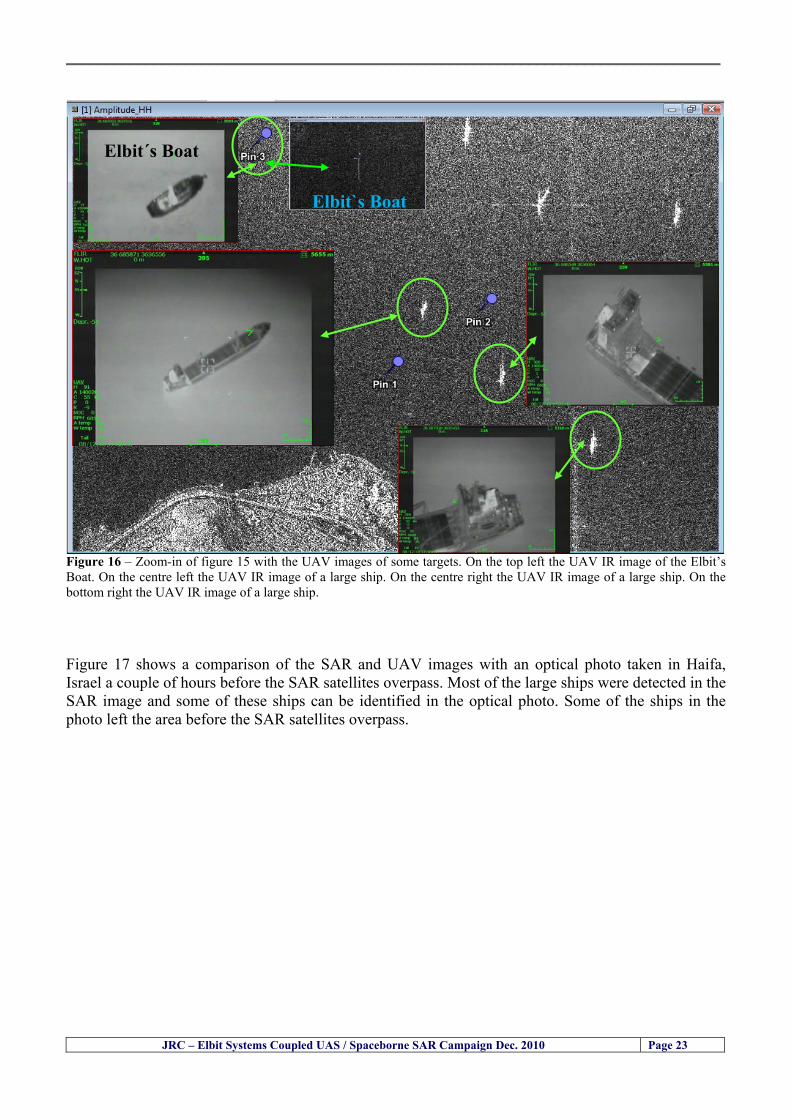
__________________________________________________________________________________
JRC ndash Elbit Systems Coupled UAS Spaceborne SAR Campaign Dec 2010 Page 23
Elbitacutes Boat
Elbit`s Boat
Figure 16 ndash Zoom-in of figure 15 with the UAV images of some targets On the top left the UAV IR image of the Elbitrsquos Boat On the centre left the UAV IR image of a large ship On the centre right the UAV IR image of a large ship On the bottom right the UAV IR image of a large ship Figure 17 shows a comparison of the SAR and UAV images with an optical photo taken in Haifa Israel a couple of hours before the SAR satellites overpass Most of the large ships were detected in the SAR image and some of these ships can be identified in the optical photo Some of the ships in the photo left the area before the SAR satellites overpass
__________________________________________________________________________________
JRC ndash Elbit Systems Coupled UAS Spaceborne SAR Campaign Dec 2010 Page 24
Figure 17 ndash Photo taken in Haifa Israel a couple of hours before the SAR satellites overpass This phot shows the large ships moored in the area Most of these large ships were detected in the Radarsat-2 image As expected their positions and orientations were slightly different at the time of the satellite overpass
Elbitacutes Boat
Elbit`s Boat
__________________________________________________________________________________
JRC ndash Elbit Systems Coupled UAS Spaceborne SAR Campaign Dec 2010 Page 25
Figure 18 ndash Photo taken in Haifa Israel a couple of hours before the SAR satellites overpass This phot shows the large ships moored in the area Most of these large ships were detected in the Radarsat-2 image As expected their positions and orientations were slightly different at the time of the satellite overpass Figure 18 illustrates the SAR image and the corresponding google earth image of a small pier in the port of Haifa In the SAR image due to several artefacts it is not possible to detect the 7 small boats moored to the small pier The UAR IR image of the same area clearly shows the 7 small boats with impressive detail taking into account that the image was acquired from an altitude of about 5500 meters A zoom in of the same UAV IR image is shown in figure 19 As it can be seen although the image was acquired from an altitude of about 5500 meters the 7 small boats can be clearly seen with enough detail to allow classification of the type of boat A UAV flight at lower altitude would probably giver a lot more detail and eventually allow the identification of the small boats
__________________________________________________________________________________
JRC ndash Elbit Systems Coupled UAS Spaceborne SAR Campaign Dec 2010 Page 26
Figure 19 ndash UAV IR image of a small pier in the port of Haifa Israel where 7 small boats can be seen with enough detail to allow classification This image was acquired from an altitude of about 5500 meters in the dark
__________________________________________________________________________________
55 ndash Quantitative Analysis of the Spaceborne SAR Image In order to allow a quantitative analysis of the data the spaceborne SAR image was calibrated using ESArsquos NEST software package version 4B The input was the SAR image acquired and the output was the Radiometric Calibration (Sigma Naught (σdeg)) expressed in terms of intensity and in decibel (dB) the Radar Brightness (βdeg) and the Radiometric Normalisation (gamma naught (γdeg))
551 ndash Radarsat-2-Spotlight 08Dec2010 (154740 UTC) Haifa Israel Figure 20 illustrates the Intensity band of a subset of the Radarsat-2Spotlgiht image (08Dec2010)
Figure 20 ndash Radarsat-2 Spotlgiht image (08Dec2010) ndash Sigma Naught (Intensity) band
JRC ndash Elbit Systems Coupled UAS Spaceborne SAR Campaign Dec 2010 Page 27
__________________________________________________________________________________
Figure 21 illustrates the Sigma Naught Coefficient of the Radarsat-2 Spotlgiht image (08Dec2010) expressed in terms of intensity and decibel (dB)
Figure 21 ndash Radarsat-2 Spotlgiht image (08Dec2010) - On the left the Sigma Naught (σdeg) (intensity) and on the right the Sigma Naught (σdeg) (dB)
ormalisation amma Naught (γdeg)) of the Radarsat-2 Spotlgiht image (08Dec2010) expressed in dB
-2 Spotlgiht image (08Dec2010) - On the left the Beta Naught (βdeg) and on the right the Gamma Naught (γdeg) (dB)
Figure 22 illustrates the Radar Brightness (Beta Naught (βdeg)) and the radiometric n(G
Figure 22 ndash Radarsat
JRC ndash Elbit Systems Coupled UAS Spaceborne SAR Campaign Dec 2010 Page 28
__________________________________________________________________________________ Figure 23 shows the Sigma Naught (σdeg) in dB after some colour manipulation and the histogram of the Sigma Naught (σdeg) image
Figure 23 ndash Radarsat-2 Spotlgiht image (08Dec2010) - On the top left the Sigma Naught (σdeg) after colour manipulation to enhance the targets and on the top right the corresponding histogram On the bottom we can see the histogram of the image
Table 6 gives the statistics of the Sigma Naught (σdeg) Radarsat-2 Spotlgiht image (08Dec2010) The Sigma Naught (σdeg) range from -72897 dB up to 23465 dB The Mean value is -16855 dB the Median is -16594 dB and the standard deviation is 7077 dB
JRC ndash Elbit Systems Coupled UAS Spaceborne SAR Campaign Dec 2010 Page 29
__________________________________________________________________________________
JRC ndash Elbit Systems Coupled UAS Spaceborne SAR Campaign Dec 2010 Page 30
Table 6 ndash Statistics of the Radarsat-2 Spotlgiht image (08Dec2010) (154740 UTC)
Statistics Values Unit Only ROI-Mask pixels considered Number of pixels total Number of considered pixels Ratio of considered pixels
No 322394283 322394283
1000
Minimum Maximum
-728974609375 234655818939209
intensity_db intensity_db
Mean Median Std-Dev Coefficient of Variation
-16855686580177853 -1659462338617847 707796800831575
07888765273432338
intensity_db intensity_db intensity_db intensity_db
Checking the radar backscattering coefficient of some targets (small boat and some large ships) detected in the Radarsat-2 Spotlight image we get values ranging from -0379 dB up to 23455 dB The analysis of the Sigma Naught values (σdeg) of the targets and the area around the targets shows a significant contrast
56 ndash Summary of the Preliminary Analysis of the Spaceborne SAR Image This experiment involved two spaceborne SAR images namely a TerraSAR-X Stripmap and one Radarsat-2 Spotlight The TerraSAR-X image was not delivered by DLR due to technical problems The Elbitrsquos boat deployed during the experiment was detected in the Radarsat-2 Spotlight image Several other targets including a set of large ships were also detected Table 7 summarises the characteristics of the SAR image acquired and the targets detected
Table 7 ndash List of SAR Satellite Images acquired during the experiment and detected boats ISRAEL (HAIFA)
Date Time Place Satellite Mode Ground Truth Data Detected Boats
08Dec2010 (PM) Haifa - Israel Radarsat-2 Spotlight GPSPhotosMovies 1 small boat deployed + 9 large ships
Table 8 gives the minimum and maximum Sigma Naught (σdeg) of the targets detected in each SAR image
Table 8 ndash Minimum and maximum Sigma Naught (σdeg) of the targets detected in each SAR image
Date Time UTC (LT)Pass Satellite Image Mode Polarisation Sigma Naught (σdeg) Min Max
29Oct2010528UTC(728AM LT) DES Radarsat-2 Spotlight HH --0379 dB 23455 dB The SAR signatures of the boats deployed were very weak Some possible reasons to explain such weak signatures are the sea state the wind speed the incidence angle and the type and materials Another possible reason is the processing at DLR
__________________________________________________________________________________
JRC ndash Elbit Systems Coupled UAS Spaceborne SAR Campaign Dec 2010 Page 31
6 ndash Preliminary Conclusions The analysis of the results of this coupled UASSpaceborne SAR experiment shows a promising potential for the use of UAS for maritime surveillance UAS can be integrated into the airborne building block of maritime surveillance systems to complement the existing assets increase system performance and improve the overall maritime domain awareness The main perceived maritime security and safety threats comprise piracy terrorist and military threats weapons proliferationsmuggling drugs trafficking illegal immigration unlawful use of containers attacks to critical infrastructures and illegal fishing The main maritime security and safety gaps include a lack of technologies with the capability of detecting small targets (eg small boats) a lack of wide area and persistent maritime surveillance a lack of coordination and information sharing limited interoperability a lack of containers security a lack of persistent surveillance of critical infrastructures and early warning systems Unmanned Aircraft Systems (UAS) are an emerging technology with strong potential to mitigate the above mentioned threats by filing in the main maritime security and safety gaps listed earlier For instance the wide range of potential applications of UAS to maritime surveillance includes but is not limited to
bull detection classification and identification of small boats bull persistent maritime surveillance bull use as communications relays bull persistent surveillance of critical infrastructures bull early warning systems bull COMINT and ELINT collection etc
Table 11 illustrates the mapping of maritime securitysafety threats vs gaps and summarises the main potential applications of UAS to maritime surveillance The above mentioned potential applications of UAS to the Maritime Domain will be addressed in turn in more detail next bull Detection classification and identification of small boats ndash The capability of detecting classifying and identifying small targets (eg small boats) is among the key technologies required to improve maritime domain awareness This capability is critical to mitigate piracy illegal immigration drugs trafficking weapons smuggling illegal fishing terrorism and critical infrastructure Unmanned Aircraft Systems (UAS) provide this capability more efficiently and at a lower cost than any other existing technology bull Persistent maritime surveillance ndash With the continuous improvements of UAS technologies such as platforms sensors collision avoidance systems command and control systems telecommunications etc UAS are increasing their autonomy endurance and flexibility These characteristics are very important for persistent maritime surveillance UAS can be launched from land ships aircraft and technologies to launch UAS from submarines are currently under development UAS have distinct advantages over other existing technologies for persistent maritime surveillance in terms of autonomyendurance (the Global Surveyor has an autonomy of 1 week) cost (eg as the autonomy of UAS increases the number of staff required to operate UAS decreases) risk (eg if the UAS crashes the crew is not at risk) flexibility (eg they can be launched from a ship reducing the time to reach potential threats) etc
__________________________________________________________________________________
JRC ndash Elbit Systems Coupled UAS Spaceborne SAR Campaign Dec 2010 Page 32
bull Communications relays ndash UAS are being used as communication relays mainly in military context but have the potential to play a similar role in Civil context in several situations such as to replace satellite communications or as a redundant system over any location on Earth The main advantages of using UAS as communication relays is that airborne communication relays mitigate kinetic and noise jamming threats to satellite communications uplinks by providing an alternative set of links either directly to surface-based terminals or to satellites beyond the range of threats They are less susceptible to noise jamming threats than satellites because an adversary has to detect geolocate and track the airborne asset and operate within line of sight of the receive antenna main beam bull Persistent surveillance of critical infrastructures ndash The security of critical infrastructures such as nuclear power plants refineries ports etc requires persistent surveillance UAS can play an important role in providing persistent surveillance over critical infrastructures and over a wide area around the critical infrastructure Some advantages of UAS over other existing technologies such as ground-based assets (eg video cameras alarm systems manned aircraft etc) comprise the security of the UAS (eg hardly can be damaged or switched off as any ground-based asset) the area covered by a UAS (eg it is larger than the area covered by any ground-based asset) the cost (eg UAS is cheaper than manned aircraft with similar capability) etc bull Early warning systems ndash UAS have the potential to be used as part of an integrated system of systems for early warning A UAS can provide information about a given area at a fraction of the cost of alternative means Formation flying of UAS can cover a wide maritime area It is reasonable to assume that in a foreseeable future with the advent of UAS with increased autonomy the operations cost of UAS will likely decrease making them increasingly more attractive bull COMINT and ELINT collection ndash SIGNal INTelligence (SIGNINT) can be divided into two categories namely COMINT and ELINT COMINT stands for Communication Intelligence and ELINT for Electronic Intelligence Collection of COMINT is passive Exploitation of COMINT requires a human operator which implies COMINT UAS are suitable for COMINT and ELINT collection in different scenarios The relatively reduced amount of data collected and analysed during this experiment and the lessons learned do not allow drawing final conclusions about the feasibility of using Unmanned Aerial Systems (UAS) for maritime surveillance However this experiment allowed hands-on experience with UAS technologies and significantly improved the awareness for its applications to maritime surveillance and related issues involved including its potential the feasibility as well as the limiting and enabling factors These different aspects will now be analysed in turn in the next sections Table 11 illustrates the mapping of the main maritime security threats and gaps as well as the main priorities in terms of the different technologies involved in maritime surveillance For each maritime threat the technologies required to fill in each gap is indicated and its priority is expressed in a range of numbers (1 to 3 1 = Maximum Priority 2 = Medium Priority 3 = Low Priority) and colours (Red = Maximum Priority Orange = Medium Priority Green = Low Priority) The main technologies involved in maritime surveillance are listed on the bottom of figure 4 and are reproduced here for convenience of the reader 1- Reporting Systems 2- Sensors 3- Platforms 4- Communications 5- Data Fusion amp Sharing 6- Intelligence and 7- Databases For example the mitigation of the main threat Piracy requires filling in several maritime security gaps (eg lack of persistent surveillance lack of wide-are maritime surveillance lack of small boat detection lack of Early Warning Systems and lack of Information Sharing with maximum priority (1- Red) and among the required technologies listed are UAS LTAAV GEO-HR etc Concerning the remaining two gaps (Limited Interoperability and Containers Security) they are less relevant to mitigate Piracy hence the priority for Limited Interoperability is 2-Orange and for Containers Security is 3- Green
__________________________________________________________________________________ Table 9 ndash The Main Maritime Security and Safety Threats vs Gaps and the technologies that can be used to mitigate them
Maritime Security Main Threats GapsGapsrarr
darrThreats
Lack o f Risk As sessmentCapab ility
La ck of Persiste nt
Surveilla nce
La ck of Wid e-Area su rve illanc e
La ck of Small Boat De tecti on
Lack o f Earl y Warn ing Sys tems
L ack of In forma tion
Sh arin g
L imi ted In terop era bility
Lac k of Co ntai ners
Se cur ity
bull PiracyUAS LTAVG EO-
HR + UAS LT AVGEO-
HR + SAR GEO-HR
+ UAS USV LTAV
+ UAS LTAV
+ Coord in ationamp Sharing +
Inter opera bilityOptimisation +
1 2 3 5 6 7 1 2 3 5 6 7 1 2 3 5 6 1 2 3 123456 4567 1234567 1234567
bull Terro rismUAS LTAVG EO-
HR + UAS L TAV GEO-HR +
SAR AISGEO-HR +
UAS USV LTAV+
Intelligence+
Inte lligen ce+
Inter opera bilityOptimisation +
Intelligence+
1 2 3 5 6 7 1 2 3 5 6 1 2 3 5 6 1 2 3 123456 4567 1234567 1234567
bull Wea pon s ofM ass Dest ru ctio n Smugg ling
UAS LTAVG EO-HR +
UAS LT AVGEO-HR +
SAR AIS+
UAS USV LTAV+
Intelligence+
Inte lligen ce+
Intelligence+
Intelligence+
1 2 3 5 6 7 1 2 3 5 6 1 2 3 5 6 1 2 3 123456 4567 1234567 1234567
bull Drug sTraffic king
UAS LTAVG EO-HR +
UAS LT AVGEO-HR +
SAR AIS+
UAS USV LTAV+
Intelligence+
Inte lligen ce+
Intelligence+
Intelligence+
1 2 3 5 6 7 1 2 3 5 6 1 2 3 5 6 1 2 3 123456 4567 1234567 1234567
bull Illega lImmigratio n
UAS LTAVG EO-HR +
UAS LT AVGEO-HR +
SAR AIS+
UAS USV LTAV+
Intelligence+
Inte lligen ce+
Intelligence+
Intelligence+
1 2 3 5 6 7 1 2 3 5 6 1 2 3 5 6 1 2 3 123456 4567 1234567 1234567
bull Critic alI nfrastruc tureSecu rit y
UAS LTAVG EO-HR +
UAS LT AVGEO-HR +
SAR AIS+
UAS USV LTAV+ + Inte lligen ce
+ Intelligence
+ Intelligence
+
1 2 3 5 6 7 1 2 3 6 1 2 3 5 6 1 2 3 123456 4567 1234567 1234567
bull Illega lFish ing
UAS LTAVG EO-HR +
AI S+SAR UASLTAV +
SAR AIS GEO-HR+
UAS USV LTAV+
Intelligence+
Inte lligen ce+
Intelligence+
1 2 3 5 6 7 1 2 3 5 7 1 2 3 5 6 1 2 3 123456 4567 1234567
bull Un lawf ul Use of Co nta iners
(Secur ity)
UAS LTAVG EO-HR +
GPS Tr acking+
Intelligence+
Inte lligen ce+
GPS Int rusion Det ection Se al
1 2 3 5 6 7 4 6 7 1 2 3 5 6 1 2 3 123456 4567 1234567 1234567
(-) Priority (+) Not Rel evant
SURVEILLANCETECHNOLOGIES
1- Reporti ng Systems
2 -Sensors 3 -P latforms 4 - Communications 5- Data Fusionamp Sharing
6 -I ntelli gence 7 -Databases
JRC ndash Elbit Systems Coupled UAS Spaceborne SAR Campaign Dec 2010 Page 33
__________________________________________________________________________________
JRC ndash Elbit Systems Coupled UAS Spaceborne SAR Campaign Dec 2010 Page 34
61 ndash Hands-on experience with UAS technologies and its applications to maritime surveillance This coupled UASSpaceborne SAR campaign was a unique opportunity to acquire further handsndashon experience with UAS technologies and learn about the main issues related to its applications to maritime surveillance From the planning phase up to the execution of the UAS flight and landing there are several factors that need to be carefully analysed and taken into account A summary of the main issues identified in this experiment is given next 1- Selection of the Experiment Area Authorisation to Fly ndash For the time being UAS can only be flown in restricted areas usually under control of national authorities often the military This is due to the risks that a UAS can pose to human life and property In the present case an area under the authority of the Israeli Civil Aviation Authority was selected The authorisation to fly was not easy to obtain because the selected area is under the authority of the Civil Aviation Authority Figure 24 indicates the area of the experiment in Haifa Israel 2- UAS Communications Issues ndash The Hermes 450 was flown in Line-of-Sight (LOS) since it was close to the coast For BLOS (Beyond Line-of-Sight) operation satellite communications are required 3- Synthetic Aperture Radar (SAR) ndash The specific model Hermes 450W used in the experiment had no SAR sensor installed However a SAR sensor can be installed A SAR sensor is important for maritime surveillance since it allows 247 operations regardless of the weather conditions 4- Automatic Identification System (AIS) Receiver ndash The Hermes 450 used in this experiment was not equipped with an AIS receiver For maritime surveillance operations an AIS receiver is a very important tool since it allows the automatic identification of most ships allowing the UAS to concentrate on non-identified ships
__________________________________________________________________________________
Figure 24 ndash The area of the experiment is indicated by the GPS Trajectory of the UAV
62 ndash Potential of UAS for Maritime Surveillance UAS technologies are relatively recent and involve a wide range of fields spanning from aeronautics and sensors technologies to satellite communications and other engineering disciplines Innovations in each of the fields involved are emerging by the day UAS still have a long way to go before they become mature and their use fully operational For the time being UAS are mainly used for military applications However a large number of non-military UAS applications have been identified by stakeholders and there are several studies and demonstration flights foreseen for the near future Maritime surveillance is one of the most challenging and promising fields of application of UAS The challenges are due to the very demanding conditions under which the UAS must operate over sea and the requirements for safe operation
JRC ndash Elbit Systems Coupled UAS Spaceborne SAR Campaign Dec 2010 Page 35
__________________________________________________________________________________
JRC ndash Elbit Systems Coupled UAS Spaceborne SAR Campaign Dec 2010 Page 36
The present UAS experiment has unveiled some of the potential of UAS for maritime surveillance The UAS tests performed during this experiment include
1 ndash Detection of a Small rubber Boat and a Fishing Ship 2 ndash Tracking of a Small Boat and a Fishing Ship 3 ndash Classification of a Small Boat and a Fishing Ship 4 ndash Identification of a Small Boat and a Fishing Ship 5 ndash Detection and Tracking of People on the Beach
Despite the operational requirement that prevented the UAS from flying bellow 3km the experiment has confirmed the capability of UAS for small boat detection tracking and classification as well as the capability for people detection and tracking Concerning the identification of the targets the characteristics of the images acquired during this mission suggest that flying at lower altitudes the UAS images would allow the identification of the targets The UAS images can be seen from Figure 15 to 20
621 ndash Advantages of UAS for maritime Surveillance Some of the advantages of using UAS for maritime surveillance have been described in the literature and are summarized bellow
1- One potential benefit of UAS is that they could fill in a gap in current maritime surveillance by improving coverage
2- The range of UAS is a significant asset when compared to border agents on patrol or stationary surveillance equipment
3- Eletro-Optical InfraRed (EOIR) sensors (cameras) can identify small size objects from very high altitudes (high resolution)
4- UAS can provide precise and near-real-time imagery to a ground control operator who would then disseminate that information so that informed decisions regarding the deployment of border patrol agents can be made quickly
5- Long endurance UAS used along the border can fly for more than 30 hours up to several days without having to refuel compared with manned helicopterrsquos average flight time of just over 2 hours
6- The ability of UAS to loiter for prolonged periods of time has important operational advantages over manned aircraft
7- The longer flight times of UAS means that sustained coverage over a previously exposed area may improve maritime security
8- The range of UAVs is a significant asset when compared to border agents on patrol or stationary surveillance equipment Nevertheless the extended range and endurance of UAVs may lessen the burdens on human resources at the borders
9- UAS accidents do not risk the lives of pilots as do the helicopters and aircraft currently used by Coast Guards for border patrolling
__________________________________________________________________________________
JRC ndash Elbit Systems Coupled UAS Spaceborne SAR Campaign Dec 2010 Page 37
622 ndash Possible Drawbacks of using UAS for maritime Surveillance UAS also have disadvantages some of them are briefly described next
1- There have been concerns regarding the high accident rate of UAS which can be multiple times higher than that of manned aircraft Because UAS technology is still evolving there is less redundancy built into the operating system of UAS than of manned aircraft and until redundant systems are perfected mishap rates are expected to remain high
2- If control systems fail in a manned aircraft a well-trained pilot is better positioned to find the source of the problem because of hisher physical proximity If a UAS encountered a similar system failure or if a UAS landing was attempted during difficult weather conditions the ground control pilot would be at a disadvantage because he or she is removed from the event Unlike a manned pilot the remote pilot would not be able to assess important sensory information such as wind speed
3- Inclement weather conditions can also impinge on a UAS surveillance capability especially UAS equipped with only an EO camera and Forward Looking Infrared Radar (FLIR) because cloudy conditions and high humidity climates can distort the imagery produced by EO and FLIR equipment The effects of extreme climatic or atmospheric conditions on sensors reportedly can be mitigated with the outfit of one synthetic aperture radar (SAR) system and a moving target indicator (MTI) radar However adding SAR and MTI to a UAS platform would increase the costs associated with using UAS
4- Depending on the type of UAS the costs of operating a UAS can be higher than the costs of operating a manned aircraft This is because some types of UAS require a significant amount of logistical support and specialized operator and maintenance training Operating one UAS may require a crew of up to 20 support personnel The high comparative costs of operating some sophisticated types of UAS may be offset somewhat by their comparatively lower unit costs
63 ndash Main Limiting Factors Preventing the Use of UAS Several pre-requisites must be satisfied to render the UAS a viable cost-effective and regulated alternative to existing resources Major civil and commercial market barriers include
Single European Sky Sense and Avoid technologies Command and Control Technologies Reliability Communications (Bandwidth LOS BLOS)
Lack of airspace regulation that covers all types of UAV systems (encompassing lsquosense and avoidrsquo airspace integration and airworthiness issues)
Affordability - price and customization issues (eg commercial off-the-shelf open modular architecture) Lack of efforts to establish joint customer requirements (although this is gradually changing) Liability for civil operation Capacity for payload flexibility Lack of sufficient secure non-military frequencies for civil operation Perceived reliability (eg vehicle attrition rate vs manned aircraft) Operator training issues Recognitioncustomer perception of the UAV market Technology developments for multi-mission capability
__________________________________________________________________________________
64 ndash UAS Key Enabling Technologies Figure 25 illustrates the components of a typical UAV System showing some of the capabilities needed and the enabling technologies required for performing a given mission Any UAV mission involves many capabilities and technologies Due to the depicted system complexity the main key players such as the US Department of Defense (DoD) and other agencies have started to use the term Unmanned Aerial System (UAS) in place of UAV
Figure 25 ndash Unmanned Aerial Vehicle System Enabled by Autonomous Mission Management Reliable Flight Systems Navigation Accurate Systems Terrain Avoidance Power and Propulsion Some UAS key enabling technologies are listed below
Autonomous Mission Management Collision Avoidance Intelligent System Health Monitoring
Reliable Flight Systems Sophisticated Contingency Management Intelligent Data Handling and Processing Over-the-Horizon Communication Network-Centric Communication Open Architecture Power and Propulsion Navigation Accurate System Technology Enhanced Structures
JRC ndash Elbit Systems Coupled UAS Spaceborne SAR Campaign Dec 2010 Page 38
__________________________________________________________________________________
JRC ndash Elbit Systems Coupled UAS Spaceborne SAR Campaign Dec 2010 Page 39
Table 12 gives a more detailed description of other critical technologies for emerging autonomous UAV systems both civil and military Most of the technologies mentioned in Table 12 apply both to civil and military UAV systems Table 10 ndash Key Enabling Technologies (from SG75 study on autonomous systems)
Critical Technologies Decision Making Software
bull Fuzzy-based decision making bull Knowledge-based system bull Case-based reasoning bull Self-learning techniques bull Decision tree evaluation bull ReasoningInferring bull Probabilisticstochastic reasoning
Prediction Algorithms bull Predictive pathintent algorithms bull Short reaction algorithm bull Effectiveness evaluation
Status Assessment Software bull Internal status analysis bull Self-orientation
Situation Analysis Software bull Situation analysis bull Environmental analysis bull External status analysis
Modelling Software bull Air vehicle modelling algorithms bull Sensor modelling algorithms bull Scenario generation bull Threat system modeling bull Attack simulation bull Mission success optimisation model bull Simulation
Sensor Processing Software bull Sensor fusion bull Area of interest identification bull Automatic target recognition
Adaptive and Self-learning Systems bull Failure self-compensation
Attack Planning Software bull Attack plans and tactical alternatives bull Plan change impact identification
Weapon Engagement Procedure Software bull Weapon engagement algorithms
Mission Plan Update Software bull Route planning system bull Payload plan management system bull Mission Success Optimisation model
Path Optimisation Software bull Optimal trajectory planning bull Path Optimisation System
Targeting Software bull Target tracking bull Target prioritisation
Platform Technologies bull Obstacle detection and avoidance (airborne) bull Obstacle detection and avoidance (ground) bull Improved autopilot bull Speech recognition
Figure 26 summarises system element designs needed to transition from current to next-generation autonomous UAV systems for civilian and military UAS
__________________________________________________________________________________
Figure 26 ndash System Element Designs Needed to Transition from Current to Next-Generation Autonomous UAV Systems These new paradigms are a combination of system attributes and technological capabilities For instance the data fusion secure anti-jam and coordinated multi-vehicle control require technological development as well as specific system development to bring full maturity to unmanned systems Finally very small Micro UAVs (MAVs) and relatively large sophisticated UCAV systems are examples of the range of UAVs that are applying the new platforms payloads onboard processing communications etc to create next generation automated UAVs It is with these new platforms payloads etc that both UCAVs and MAV will be able to address similar operational challenges including
Mixed operation with other assets bull Deconfliction collision avoidance C4I integration
Operation over populated areas bull Safety issues Need to reduce reliance on communications bull UCAV ndash countermeasures bull MAV ndash limited size and power bull Limited line of sight environment Need a fully integrated system bull MAV propulsionpower generation still critical bull Operator machine interface critical bull All weather operations bull Survivability
JRC ndash Elbit Systems Coupled UAS Spaceborne SAR Campaign Dec 2010 Page 40
__________________________________________________________________________________
JRC ndash Elbit Systems Coupled UAS Spaceborne SAR Campaign Dec 2010 Page 41
65 ndash Mission Readiness
651 ndash Mission Readiness Summary This section summarises civil UAV mission readiness The purpose of Mission Readiness is to assess the readiness status of the different technologies involved in UAS In the present case this civil UAV mission readiness based on technology maturation forecasts that meet or exceed the desired or required capabilities identified by the user community Figure 27 summarises the mission readiness time forecasts for the different technologies The technologies annotated with an asterisk () are shown within the figure with maturation forecasts based on development targets expressed in the US Department of Defencesrsquo UAV Roadmap document The purpose of the chart is to be able to identify when the capability to fly a particular mission can be expected as a function of time The left-most end is the least probable and the right end the most probable timeframe
Figure 27 ndash Technology Maturation Summaries in Terms of Mission-Derived Capabilities
__________________________________________________________________________________
JRC ndash Elbit Systems Coupled UAS Spaceborne SAR Campaign Dec 2010 Page 42
66 ndash Small Boat Detection in SAR Satellite Imagery The use of spaceborne SAR imagery for small boat detection requires additional small boat detection experiments under different conditions using different methods It is not possible to draw final conclusions based on a limited number of small boat detection experiments which are not representative of the multiple possible scenarios
67 ndash Limitations of current State-of-the-Art SAR Satellite technology The main limitations of current State-of-the-Art spaceborne SAR imagery for maritime surveillance in particular aimed at small boat detection are 1 - SAR satellites repeat cycles do not allow the coverage of the same area at the required time intervals Constellations of SAR satellites could be a solution 2 - The conflict between resolution and image swath High resolution is required to detect small boats However the high resolution images have small swaths Maritime surveillance with high resolution images would require a large number of images to cover wide maritime areas which is very expensive and for the time being technically not feasible Intelligence data can play an important role by indicating an approximate position of suspicious non cooperative targets therefore reducing the surveillance area which can then be imaged using high resolution images 3- Spaceborne high resolution SAR imagery acquisition times are long enough to allow significant motion of the target during the acquisition time degrading the quality of the image Further research efforts are needed to develop new sensors and platforms As far as sensors are concerned shorter integration times are needed to prevent the blurring effect caused by the motion of the targets Regarding the platforms more platforms are needed to allow lower repeat cycles and improved coverage
__________________________________________________________________________________
JRC ndash Elbit Systems Coupled UAS Spaceborne SAR Campaign Dec 2010 Page 43
7 ndash Plans for Future Work The controlled experiments carried out by the EC-JRC together with Elbit Systems in Haifa-Israel comprised the deployment of a UAS (Hermes-450) and one small 12-meter boat A Radarsat-2 Spotlight image was acquired and several images collected by the Hermes-450 The experiment unveiled the potential of UAS for maritime surveillance in particular for detection tracking classification and possible identification of small targets The UAS was able to detect track and classify small targets such as small boats For low UAS altitude flights identification may be possible in some cases The small 12-meter boat was detected in the spaceborne SAR image The small boat detection trials carried out by the JRC were very successful since most small boats deployed during the experiments were detected in different sea states wind speeds and geographical locations The several small boat detection campaigns conducted by the EC-JRC seem to suggest that the probability of detection of small boats in spaceborne SAR images strongly depends on factors such as the sea state the wind speed the type of boat (shape and materials) the weather conditions among other factors The results of the experiments conducted thus far are not enough to draw final conclusions about the feasibility of using spaceborne SAR imagery for small boat detection However the experiments have an overall positive outcome because they indicate that under suitable sea state and wind speed conditions it is possible to detect small boats using spaceborne SAR The estimation of the probability of detection of small boats in spaceborne SAR images requires a large number of experiments under different circumstances (eg sea state wind speed characteristics of the targets image type and mode etc) Future plans include additional UAS experiments to asses its potential for maritime surveillance
Acknowledgements ndash The authors would like to express their gratitude to Elbit Systems for their cooperation logistical support and assets deployed without which the present coupled UASSAR Satellite Small Boat Detection Campaign would have not been possible
__________________________________________________________________________________
JRC ndash Elbit Systems Coupled UAS Spaceborne SAR Campaign Dec 2010 Page 44
REFERENCES [1] Elbit Systems ldquoUAV Elbit Systems Proposal for Unmanned Aerial Vehicle (UAV) flight to
collect Ground Truth data during a Maritime Surveillance Campaign and demonstrate UAV capabilities for Maritime Surveillancerdquo 2010
[2] ndash Cheryl Yuhas Suborbital Science Program Manager NASA Science Mission Directorate ldquoEarth Observations and the Role of UAVs A Capabilities Assessment Version 11rdquo Civil UAV Assessment Team httpwwwnasagovcentersdrydenresearchcivuavindexhtml August 2006
[3] ndash Document NIAG (SG75) NATO Industrial Advisory Group Study Group 75 Pre-Feasibility Study on UAV Autonomous Operations 2004
[4] ndash United States Department of Defence (DoD) Directive 50001 ldquoThe Defense Acquisition Systemrdquo and DoD Instruction 50002 ldquoOperation of the Defense Acquisition Systemrdquo
[5] ndash Mr James Ramage Mr Massimo Avalle Dr Erik Berglund Dr Luigi Crovella Mr Robert Frampton Dr Uwe Krogmann Mr Christian Ravat Mr Mike Robinson Dr Axel Schulte Dr Scott Wood ldquoRTO-TR-SCI-118 - Automation Technologies and Application Considerations for Highly Integrated Mission Systemsrdquo RTO-TR-SCI-118 AC323(SCI-118)TP204 January 2009
[6] Victor MG Silva Gilles Jurquet Gabriel Marchalot Maria TG Calzado Txema Soroa Juan Sancho Adam Koubek Harm Greidanus and Claudio Savarino ldquoWide Maritime Area Airborne Surveillance (WIMA2S) WP5 Final Reportrdquo WIMAAS WP5 FP7 Project 2008-2011 - ISBN-978-92-79-22801-8 (print) 978-92-79-22802-5 (PDF) ISSN-1018-5593 (print) 1831-9424 (online) EC-JRC Scientific Report JRC 70093 2012
[7] Victor MG Silva and Harm Greidanus ldquoSpaceborne SAR Small Boat Detection Campaign in Portugal and Spainrdquo EUR 25281 EN ISBN 978-92-79-22553-6 ISSN 1831-9424 (online) EC-JRC Scientific Report JRC68160 2012
[8] Goncalves Da Silva V Van Wimersma Greidanus H Hejmanowska B Loudjani P ldquoUAS Applications With Societal Benefits ndash JRCrsquos UAS-Related Activitiesrdquo 2011-2012 UAS Yearbook - UAS Unmanned Aircraft Systems - The Global Perspective 9 (9) 2011 p 127-129 JRC66600
[9] Goncalves Da Silva V Van Wimersma Greidanus H ldquoSmall boat detection using TerraSAR-X and Radarsat2 satellite imageryrdquo 4th TerraSAR-X Science Team Meeting 14 February 2011 DLR Oberpfaffenhofen (Germany) German Aerospace Center (DLR) (Organiser) 2011 JRC63663
[10] V Silva Harm Greidanus ldquoJRC - SAR Satellite Small Boat Detection Campaign - Portoroz ndash Sloveniardquo - ISBN-13 978-92-79-21476-9 ISSN (online) 1831-9424 EC-JRC Scientific Report JRC66835 2011
[11] V Silva Harm Greidanus ldquoJRC - SAR satellite small boat detection campaign - Algarve Portugalrdquo - ISBN-13 978-92-79-21265-9 ISSN (online) 1831-9424 ISSN (print) 1018-5593 EC-JRC Scientific Report JRC66631 2011
[12] ndash Goncalves Da Silva V Van Wimersma Greidanus H ldquoJRC-Frontex Spaceborne SAR Small Boat Detection Campaign ndash Italy amp Spainrdquo - ISBN-13 978-92-79-22213-9 ISSN (online) 1831-9424 EC-JRC Scientific Report JRC67517 2011
[13] - PW Vachon SJ Thomas J Cranton HR Edel and MD Henschel Validation of ship detection by the RADARSAT synthetic aperture radar and the Ocean Monitoring Workstation Canadian Journal of Remote Sensing 26(3)200ndash212 2000
[14] - Crisp D (2004) The state-of-the-art in ship detection in Synthetic Aperture Radar imagery DSTO Information Sciences Laboratory Australia
[15] - Joint Research Centre (JRC) of the European Community mdash IMPAST and DECLIMS web site httpintelligencejrcceceuintmarinefishindexhtm
[16] - McCandless SW Jackson CR (2004) Principles of Synthetic Aperture Radar Synthetic Aperture Radar Marine Users Manual NOAA Washington pp 1-23
[17] - Greidanus H (2008) Satellite Imaging for Maritime Surveillance of the European Seas Remote Sensing of the European Seas 343-358
European Commission
EUR 25346 EN --- Joint Research Centre --- Institute for the Protection and Security of the Citizen
Title JRC --- Elbit Systems Coupled UAS and Spaceborne SAR Campaign in Israel
Authors Victor MG Silva Harm Greidanus
Luxembourg Publications Office of the European Union
2012 --- v+44 pp --- 210 x 297 cm
EUR --- Scientific and Technical Research series --- ISSN 181-9424 (online) ISSN 1018-5593 (print)
ISBN 978-92-79-25020-0
doi10278828527
Abstract The European maritime area is one of Europersquos most important assets with regard to resources security and ultimately
prosperity of the Member States A significant part of Europersquos economy relies directly or indirectly on it It is not just the
shipping or fisheries industries and their related activities It is also shipbuilding and ports marine equipment and offshore
energy maritime and coastal tourism aquaculture submarine telecommunications blue biotech and the protection of the
marine environment The European maritime area faces several risks and threats posed by unlawful activities such as drugs
trafficking smuggling illegal immigration organised crime and terrorism Piracy in international waters also constitutes a threat
to Europe since it can disrupt the maritime transport chain These risks and threats can endanger human lives marine resources
and the environment as well as significantly disrupt the transport chain and global and local security It is anticipated that these
risks and threats will endure in the mid and long run In order to keep Europe as a world leader in the global maritime economy
an effective integratedinteroperable sustainable maritime surveillance system and situational awareness are needed
A significant number of unlawful maritime activities such as illegal immigration drugs trafficking smuggling piracy and
terrorism involve mainly small boats because small boats are faster and more difficult to detect using conventional means
Hence it is very important to find out the feasibility of using Unmanned Aerial Systems (UAS) for small boat detection tracking
classification and identification as well as to study the potential of UAS for maritime surveillance Since 2010 the EC-JRC has
carried out a number of UAS maritime surveillance campaigns to study the potential of UAS for maritime surveillance in
particular for small boat detection This report presents the results and conclusions of the JRC --- Elbit Systems Coupled UAS and
Spaceborne SAR campaign carried out in Dec 2010 in Haifa Israel
As the Commissionrsquos in-house science service the Joint Research Centrersquos mission is to provide EU policies with independent evidence-based scientific and technical support throughout the whole policy cycle Working in close cooperation with policy Directorates-General the JRC addresses key societal challenges while stimulating innovation through developing new standards methods and tools and sharing and transferring its know-how to the Member States and international community Key policy areas include environment and climate change energy and transport agriculture and food security health and consumer protection information society and digital agenda safety and security including nuclear all supported through a cross-cutting and multi-disciplinary approach
LB-NA-25346-EN
-N
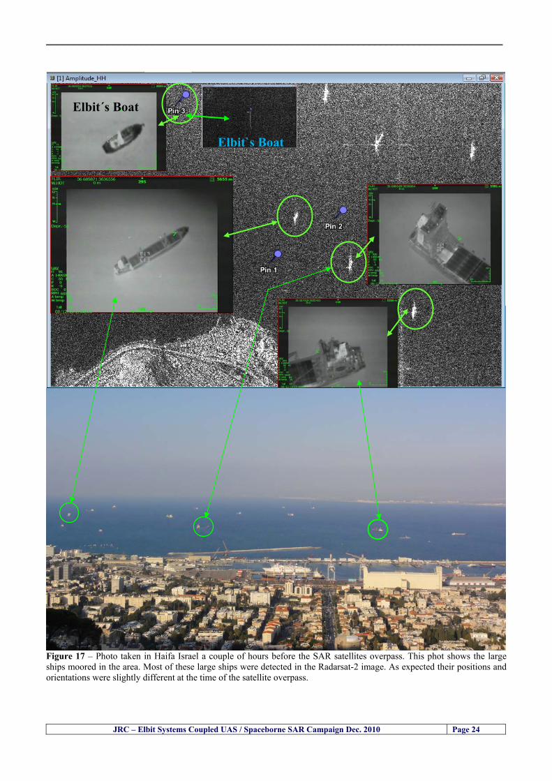
__________________________________________________________________________________
JRC ndash Elbit Systems Coupled UAS Spaceborne SAR Campaign Dec 2010 Page 24
Figure 17 ndash Photo taken in Haifa Israel a couple of hours before the SAR satellites overpass This phot shows the large ships moored in the area Most of these large ships were detected in the Radarsat-2 image As expected their positions and orientations were slightly different at the time of the satellite overpass
Elbitacutes Boat
Elbit`s Boat
__________________________________________________________________________________
JRC ndash Elbit Systems Coupled UAS Spaceborne SAR Campaign Dec 2010 Page 25
Figure 18 ndash Photo taken in Haifa Israel a couple of hours before the SAR satellites overpass This phot shows the large ships moored in the area Most of these large ships were detected in the Radarsat-2 image As expected their positions and orientations were slightly different at the time of the satellite overpass Figure 18 illustrates the SAR image and the corresponding google earth image of a small pier in the port of Haifa In the SAR image due to several artefacts it is not possible to detect the 7 small boats moored to the small pier The UAR IR image of the same area clearly shows the 7 small boats with impressive detail taking into account that the image was acquired from an altitude of about 5500 meters A zoom in of the same UAV IR image is shown in figure 19 As it can be seen although the image was acquired from an altitude of about 5500 meters the 7 small boats can be clearly seen with enough detail to allow classification of the type of boat A UAV flight at lower altitude would probably giver a lot more detail and eventually allow the identification of the small boats
__________________________________________________________________________________
JRC ndash Elbit Systems Coupled UAS Spaceborne SAR Campaign Dec 2010 Page 26
Figure 19 ndash UAV IR image of a small pier in the port of Haifa Israel where 7 small boats can be seen with enough detail to allow classification This image was acquired from an altitude of about 5500 meters in the dark
__________________________________________________________________________________
55 ndash Quantitative Analysis of the Spaceborne SAR Image In order to allow a quantitative analysis of the data the spaceborne SAR image was calibrated using ESArsquos NEST software package version 4B The input was the SAR image acquired and the output was the Radiometric Calibration (Sigma Naught (σdeg)) expressed in terms of intensity and in decibel (dB) the Radar Brightness (βdeg) and the Radiometric Normalisation (gamma naught (γdeg))
551 ndash Radarsat-2-Spotlight 08Dec2010 (154740 UTC) Haifa Israel Figure 20 illustrates the Intensity band of a subset of the Radarsat-2Spotlgiht image (08Dec2010)
Figure 20 ndash Radarsat-2 Spotlgiht image (08Dec2010) ndash Sigma Naught (Intensity) band
JRC ndash Elbit Systems Coupled UAS Spaceborne SAR Campaign Dec 2010 Page 27
__________________________________________________________________________________
Figure 21 illustrates the Sigma Naught Coefficient of the Radarsat-2 Spotlgiht image (08Dec2010) expressed in terms of intensity and decibel (dB)
Figure 21 ndash Radarsat-2 Spotlgiht image (08Dec2010) - On the left the Sigma Naught (σdeg) (intensity) and on the right the Sigma Naught (σdeg) (dB)
ormalisation amma Naught (γdeg)) of the Radarsat-2 Spotlgiht image (08Dec2010) expressed in dB
-2 Spotlgiht image (08Dec2010) - On the left the Beta Naught (βdeg) and on the right the Gamma Naught (γdeg) (dB)
Figure 22 illustrates the Radar Brightness (Beta Naught (βdeg)) and the radiometric n(G
Figure 22 ndash Radarsat
JRC ndash Elbit Systems Coupled UAS Spaceborne SAR Campaign Dec 2010 Page 28
__________________________________________________________________________________ Figure 23 shows the Sigma Naught (σdeg) in dB after some colour manipulation and the histogram of the Sigma Naught (σdeg) image
Figure 23 ndash Radarsat-2 Spotlgiht image (08Dec2010) - On the top left the Sigma Naught (σdeg) after colour manipulation to enhance the targets and on the top right the corresponding histogram On the bottom we can see the histogram of the image
Table 6 gives the statistics of the Sigma Naught (σdeg) Radarsat-2 Spotlgiht image (08Dec2010) The Sigma Naught (σdeg) range from -72897 dB up to 23465 dB The Mean value is -16855 dB the Median is -16594 dB and the standard deviation is 7077 dB
JRC ndash Elbit Systems Coupled UAS Spaceborne SAR Campaign Dec 2010 Page 29
__________________________________________________________________________________
JRC ndash Elbit Systems Coupled UAS Spaceborne SAR Campaign Dec 2010 Page 30
Table 6 ndash Statistics of the Radarsat-2 Spotlgiht image (08Dec2010) (154740 UTC)
Statistics Values Unit Only ROI-Mask pixels considered Number of pixels total Number of considered pixels Ratio of considered pixels
No 322394283 322394283
1000
Minimum Maximum
-728974609375 234655818939209
intensity_db intensity_db
Mean Median Std-Dev Coefficient of Variation
-16855686580177853 -1659462338617847 707796800831575
07888765273432338
intensity_db intensity_db intensity_db intensity_db
Checking the radar backscattering coefficient of some targets (small boat and some large ships) detected in the Radarsat-2 Spotlight image we get values ranging from -0379 dB up to 23455 dB The analysis of the Sigma Naught values (σdeg) of the targets and the area around the targets shows a significant contrast
56 ndash Summary of the Preliminary Analysis of the Spaceborne SAR Image This experiment involved two spaceborne SAR images namely a TerraSAR-X Stripmap and one Radarsat-2 Spotlight The TerraSAR-X image was not delivered by DLR due to technical problems The Elbitrsquos boat deployed during the experiment was detected in the Radarsat-2 Spotlight image Several other targets including a set of large ships were also detected Table 7 summarises the characteristics of the SAR image acquired and the targets detected
Table 7 ndash List of SAR Satellite Images acquired during the experiment and detected boats ISRAEL (HAIFA)
Date Time Place Satellite Mode Ground Truth Data Detected Boats
08Dec2010 (PM) Haifa - Israel Radarsat-2 Spotlight GPSPhotosMovies 1 small boat deployed + 9 large ships
Table 8 gives the minimum and maximum Sigma Naught (σdeg) of the targets detected in each SAR image
Table 8 ndash Minimum and maximum Sigma Naught (σdeg) of the targets detected in each SAR image
Date Time UTC (LT)Pass Satellite Image Mode Polarisation Sigma Naught (σdeg) Min Max
29Oct2010528UTC(728AM LT) DES Radarsat-2 Spotlight HH --0379 dB 23455 dB The SAR signatures of the boats deployed were very weak Some possible reasons to explain such weak signatures are the sea state the wind speed the incidence angle and the type and materials Another possible reason is the processing at DLR
__________________________________________________________________________________
JRC ndash Elbit Systems Coupled UAS Spaceborne SAR Campaign Dec 2010 Page 31
6 ndash Preliminary Conclusions The analysis of the results of this coupled UASSpaceborne SAR experiment shows a promising potential for the use of UAS for maritime surveillance UAS can be integrated into the airborne building block of maritime surveillance systems to complement the existing assets increase system performance and improve the overall maritime domain awareness The main perceived maritime security and safety threats comprise piracy terrorist and military threats weapons proliferationsmuggling drugs trafficking illegal immigration unlawful use of containers attacks to critical infrastructures and illegal fishing The main maritime security and safety gaps include a lack of technologies with the capability of detecting small targets (eg small boats) a lack of wide area and persistent maritime surveillance a lack of coordination and information sharing limited interoperability a lack of containers security a lack of persistent surveillance of critical infrastructures and early warning systems Unmanned Aircraft Systems (UAS) are an emerging technology with strong potential to mitigate the above mentioned threats by filing in the main maritime security and safety gaps listed earlier For instance the wide range of potential applications of UAS to maritime surveillance includes but is not limited to
bull detection classification and identification of small boats bull persistent maritime surveillance bull use as communications relays bull persistent surveillance of critical infrastructures bull early warning systems bull COMINT and ELINT collection etc
Table 11 illustrates the mapping of maritime securitysafety threats vs gaps and summarises the main potential applications of UAS to maritime surveillance The above mentioned potential applications of UAS to the Maritime Domain will be addressed in turn in more detail next bull Detection classification and identification of small boats ndash The capability of detecting classifying and identifying small targets (eg small boats) is among the key technologies required to improve maritime domain awareness This capability is critical to mitigate piracy illegal immigration drugs trafficking weapons smuggling illegal fishing terrorism and critical infrastructure Unmanned Aircraft Systems (UAS) provide this capability more efficiently and at a lower cost than any other existing technology bull Persistent maritime surveillance ndash With the continuous improvements of UAS technologies such as platforms sensors collision avoidance systems command and control systems telecommunications etc UAS are increasing their autonomy endurance and flexibility These characteristics are very important for persistent maritime surveillance UAS can be launched from land ships aircraft and technologies to launch UAS from submarines are currently under development UAS have distinct advantages over other existing technologies for persistent maritime surveillance in terms of autonomyendurance (the Global Surveyor has an autonomy of 1 week) cost (eg as the autonomy of UAS increases the number of staff required to operate UAS decreases) risk (eg if the UAS crashes the crew is not at risk) flexibility (eg they can be launched from a ship reducing the time to reach potential threats) etc
__________________________________________________________________________________
JRC ndash Elbit Systems Coupled UAS Spaceborne SAR Campaign Dec 2010 Page 32
bull Communications relays ndash UAS are being used as communication relays mainly in military context but have the potential to play a similar role in Civil context in several situations such as to replace satellite communications or as a redundant system over any location on Earth The main advantages of using UAS as communication relays is that airborne communication relays mitigate kinetic and noise jamming threats to satellite communications uplinks by providing an alternative set of links either directly to surface-based terminals or to satellites beyond the range of threats They are less susceptible to noise jamming threats than satellites because an adversary has to detect geolocate and track the airborne asset and operate within line of sight of the receive antenna main beam bull Persistent surveillance of critical infrastructures ndash The security of critical infrastructures such as nuclear power plants refineries ports etc requires persistent surveillance UAS can play an important role in providing persistent surveillance over critical infrastructures and over a wide area around the critical infrastructure Some advantages of UAS over other existing technologies such as ground-based assets (eg video cameras alarm systems manned aircraft etc) comprise the security of the UAS (eg hardly can be damaged or switched off as any ground-based asset) the area covered by a UAS (eg it is larger than the area covered by any ground-based asset) the cost (eg UAS is cheaper than manned aircraft with similar capability) etc bull Early warning systems ndash UAS have the potential to be used as part of an integrated system of systems for early warning A UAS can provide information about a given area at a fraction of the cost of alternative means Formation flying of UAS can cover a wide maritime area It is reasonable to assume that in a foreseeable future with the advent of UAS with increased autonomy the operations cost of UAS will likely decrease making them increasingly more attractive bull COMINT and ELINT collection ndash SIGNal INTelligence (SIGNINT) can be divided into two categories namely COMINT and ELINT COMINT stands for Communication Intelligence and ELINT for Electronic Intelligence Collection of COMINT is passive Exploitation of COMINT requires a human operator which implies COMINT UAS are suitable for COMINT and ELINT collection in different scenarios The relatively reduced amount of data collected and analysed during this experiment and the lessons learned do not allow drawing final conclusions about the feasibility of using Unmanned Aerial Systems (UAS) for maritime surveillance However this experiment allowed hands-on experience with UAS technologies and significantly improved the awareness for its applications to maritime surveillance and related issues involved including its potential the feasibility as well as the limiting and enabling factors These different aspects will now be analysed in turn in the next sections Table 11 illustrates the mapping of the main maritime security threats and gaps as well as the main priorities in terms of the different technologies involved in maritime surveillance For each maritime threat the technologies required to fill in each gap is indicated and its priority is expressed in a range of numbers (1 to 3 1 = Maximum Priority 2 = Medium Priority 3 = Low Priority) and colours (Red = Maximum Priority Orange = Medium Priority Green = Low Priority) The main technologies involved in maritime surveillance are listed on the bottom of figure 4 and are reproduced here for convenience of the reader 1- Reporting Systems 2- Sensors 3- Platforms 4- Communications 5- Data Fusion amp Sharing 6- Intelligence and 7- Databases For example the mitigation of the main threat Piracy requires filling in several maritime security gaps (eg lack of persistent surveillance lack of wide-are maritime surveillance lack of small boat detection lack of Early Warning Systems and lack of Information Sharing with maximum priority (1- Red) and among the required technologies listed are UAS LTAAV GEO-HR etc Concerning the remaining two gaps (Limited Interoperability and Containers Security) they are less relevant to mitigate Piracy hence the priority for Limited Interoperability is 2-Orange and for Containers Security is 3- Green
__________________________________________________________________________________ Table 9 ndash The Main Maritime Security and Safety Threats vs Gaps and the technologies that can be used to mitigate them
Maritime Security Main Threats GapsGapsrarr
darrThreats
Lack o f Risk As sessmentCapab ility
La ck of Persiste nt
Surveilla nce
La ck of Wid e-Area su rve illanc e
La ck of Small Boat De tecti on
Lack o f Earl y Warn ing Sys tems
L ack of In forma tion
Sh arin g
L imi ted In terop era bility
Lac k of Co ntai ners
Se cur ity
bull PiracyUAS LTAVG EO-
HR + UAS LT AVGEO-
HR + SAR GEO-HR
+ UAS USV LTAV
+ UAS LTAV
+ Coord in ationamp Sharing +
Inter opera bilityOptimisation +
1 2 3 5 6 7 1 2 3 5 6 7 1 2 3 5 6 1 2 3 123456 4567 1234567 1234567
bull Terro rismUAS LTAVG EO-
HR + UAS L TAV GEO-HR +
SAR AISGEO-HR +
UAS USV LTAV+
Intelligence+
Inte lligen ce+
Inter opera bilityOptimisation +
Intelligence+
1 2 3 5 6 7 1 2 3 5 6 1 2 3 5 6 1 2 3 123456 4567 1234567 1234567
bull Wea pon s ofM ass Dest ru ctio n Smugg ling
UAS LTAVG EO-HR +
UAS LT AVGEO-HR +
SAR AIS+
UAS USV LTAV+
Intelligence+
Inte lligen ce+
Intelligence+
Intelligence+
1 2 3 5 6 7 1 2 3 5 6 1 2 3 5 6 1 2 3 123456 4567 1234567 1234567
bull Drug sTraffic king
UAS LTAVG EO-HR +
UAS LT AVGEO-HR +
SAR AIS+
UAS USV LTAV+
Intelligence+
Inte lligen ce+
Intelligence+
Intelligence+
1 2 3 5 6 7 1 2 3 5 6 1 2 3 5 6 1 2 3 123456 4567 1234567 1234567
bull Illega lImmigratio n
UAS LTAVG EO-HR +
UAS LT AVGEO-HR +
SAR AIS+
UAS USV LTAV+
Intelligence+
Inte lligen ce+
Intelligence+
Intelligence+
1 2 3 5 6 7 1 2 3 5 6 1 2 3 5 6 1 2 3 123456 4567 1234567 1234567
bull Critic alI nfrastruc tureSecu rit y
UAS LTAVG EO-HR +
UAS LT AVGEO-HR +
SAR AIS+
UAS USV LTAV+ + Inte lligen ce
+ Intelligence
+ Intelligence
+
1 2 3 5 6 7 1 2 3 6 1 2 3 5 6 1 2 3 123456 4567 1234567 1234567
bull Illega lFish ing
UAS LTAVG EO-HR +
AI S+SAR UASLTAV +
SAR AIS GEO-HR+
UAS USV LTAV+
Intelligence+
Inte lligen ce+
Intelligence+
1 2 3 5 6 7 1 2 3 5 7 1 2 3 5 6 1 2 3 123456 4567 1234567
bull Un lawf ul Use of Co nta iners
(Secur ity)
UAS LTAVG EO-HR +
GPS Tr acking+
Intelligence+
Inte lligen ce+
GPS Int rusion Det ection Se al
1 2 3 5 6 7 4 6 7 1 2 3 5 6 1 2 3 123456 4567 1234567 1234567
(-) Priority (+) Not Rel evant
SURVEILLANCETECHNOLOGIES
1- Reporti ng Systems
2 -Sensors 3 -P latforms 4 - Communications 5- Data Fusionamp Sharing
6 -I ntelli gence 7 -Databases
JRC ndash Elbit Systems Coupled UAS Spaceborne SAR Campaign Dec 2010 Page 33
__________________________________________________________________________________
JRC ndash Elbit Systems Coupled UAS Spaceborne SAR Campaign Dec 2010 Page 34
61 ndash Hands-on experience with UAS technologies and its applications to maritime surveillance This coupled UASSpaceborne SAR campaign was a unique opportunity to acquire further handsndashon experience with UAS technologies and learn about the main issues related to its applications to maritime surveillance From the planning phase up to the execution of the UAS flight and landing there are several factors that need to be carefully analysed and taken into account A summary of the main issues identified in this experiment is given next 1- Selection of the Experiment Area Authorisation to Fly ndash For the time being UAS can only be flown in restricted areas usually under control of national authorities often the military This is due to the risks that a UAS can pose to human life and property In the present case an area under the authority of the Israeli Civil Aviation Authority was selected The authorisation to fly was not easy to obtain because the selected area is under the authority of the Civil Aviation Authority Figure 24 indicates the area of the experiment in Haifa Israel 2- UAS Communications Issues ndash The Hermes 450 was flown in Line-of-Sight (LOS) since it was close to the coast For BLOS (Beyond Line-of-Sight) operation satellite communications are required 3- Synthetic Aperture Radar (SAR) ndash The specific model Hermes 450W used in the experiment had no SAR sensor installed However a SAR sensor can be installed A SAR sensor is important for maritime surveillance since it allows 247 operations regardless of the weather conditions 4- Automatic Identification System (AIS) Receiver ndash The Hermes 450 used in this experiment was not equipped with an AIS receiver For maritime surveillance operations an AIS receiver is a very important tool since it allows the automatic identification of most ships allowing the UAS to concentrate on non-identified ships
__________________________________________________________________________________
Figure 24 ndash The area of the experiment is indicated by the GPS Trajectory of the UAV
62 ndash Potential of UAS for Maritime Surveillance UAS technologies are relatively recent and involve a wide range of fields spanning from aeronautics and sensors technologies to satellite communications and other engineering disciplines Innovations in each of the fields involved are emerging by the day UAS still have a long way to go before they become mature and their use fully operational For the time being UAS are mainly used for military applications However a large number of non-military UAS applications have been identified by stakeholders and there are several studies and demonstration flights foreseen for the near future Maritime surveillance is one of the most challenging and promising fields of application of UAS The challenges are due to the very demanding conditions under which the UAS must operate over sea and the requirements for safe operation
JRC ndash Elbit Systems Coupled UAS Spaceborne SAR Campaign Dec 2010 Page 35
__________________________________________________________________________________
JRC ndash Elbit Systems Coupled UAS Spaceborne SAR Campaign Dec 2010 Page 36
The present UAS experiment has unveiled some of the potential of UAS for maritime surveillance The UAS tests performed during this experiment include
1 ndash Detection of a Small rubber Boat and a Fishing Ship 2 ndash Tracking of a Small Boat and a Fishing Ship 3 ndash Classification of a Small Boat and a Fishing Ship 4 ndash Identification of a Small Boat and a Fishing Ship 5 ndash Detection and Tracking of People on the Beach
Despite the operational requirement that prevented the UAS from flying bellow 3km the experiment has confirmed the capability of UAS for small boat detection tracking and classification as well as the capability for people detection and tracking Concerning the identification of the targets the characteristics of the images acquired during this mission suggest that flying at lower altitudes the UAS images would allow the identification of the targets The UAS images can be seen from Figure 15 to 20
621 ndash Advantages of UAS for maritime Surveillance Some of the advantages of using UAS for maritime surveillance have been described in the literature and are summarized bellow
1- One potential benefit of UAS is that they could fill in a gap in current maritime surveillance by improving coverage
2- The range of UAS is a significant asset when compared to border agents on patrol or stationary surveillance equipment
3- Eletro-Optical InfraRed (EOIR) sensors (cameras) can identify small size objects from very high altitudes (high resolution)
4- UAS can provide precise and near-real-time imagery to a ground control operator who would then disseminate that information so that informed decisions regarding the deployment of border patrol agents can be made quickly
5- Long endurance UAS used along the border can fly for more than 30 hours up to several days without having to refuel compared with manned helicopterrsquos average flight time of just over 2 hours
6- The ability of UAS to loiter for prolonged periods of time has important operational advantages over manned aircraft
7- The longer flight times of UAS means that sustained coverage over a previously exposed area may improve maritime security
8- The range of UAVs is a significant asset when compared to border agents on patrol or stationary surveillance equipment Nevertheless the extended range and endurance of UAVs may lessen the burdens on human resources at the borders
9- UAS accidents do not risk the lives of pilots as do the helicopters and aircraft currently used by Coast Guards for border patrolling
__________________________________________________________________________________
JRC ndash Elbit Systems Coupled UAS Spaceborne SAR Campaign Dec 2010 Page 37
622 ndash Possible Drawbacks of using UAS for maritime Surveillance UAS also have disadvantages some of them are briefly described next
1- There have been concerns regarding the high accident rate of UAS which can be multiple times higher than that of manned aircraft Because UAS technology is still evolving there is less redundancy built into the operating system of UAS than of manned aircraft and until redundant systems are perfected mishap rates are expected to remain high
2- If control systems fail in a manned aircraft a well-trained pilot is better positioned to find the source of the problem because of hisher physical proximity If a UAS encountered a similar system failure or if a UAS landing was attempted during difficult weather conditions the ground control pilot would be at a disadvantage because he or she is removed from the event Unlike a manned pilot the remote pilot would not be able to assess important sensory information such as wind speed
3- Inclement weather conditions can also impinge on a UAS surveillance capability especially UAS equipped with only an EO camera and Forward Looking Infrared Radar (FLIR) because cloudy conditions and high humidity climates can distort the imagery produced by EO and FLIR equipment The effects of extreme climatic or atmospheric conditions on sensors reportedly can be mitigated with the outfit of one synthetic aperture radar (SAR) system and a moving target indicator (MTI) radar However adding SAR and MTI to a UAS platform would increase the costs associated with using UAS
4- Depending on the type of UAS the costs of operating a UAS can be higher than the costs of operating a manned aircraft This is because some types of UAS require a significant amount of logistical support and specialized operator and maintenance training Operating one UAS may require a crew of up to 20 support personnel The high comparative costs of operating some sophisticated types of UAS may be offset somewhat by their comparatively lower unit costs
63 ndash Main Limiting Factors Preventing the Use of UAS Several pre-requisites must be satisfied to render the UAS a viable cost-effective and regulated alternative to existing resources Major civil and commercial market barriers include
Single European Sky Sense and Avoid technologies Command and Control Technologies Reliability Communications (Bandwidth LOS BLOS)
Lack of airspace regulation that covers all types of UAV systems (encompassing lsquosense and avoidrsquo airspace integration and airworthiness issues)
Affordability - price and customization issues (eg commercial off-the-shelf open modular architecture) Lack of efforts to establish joint customer requirements (although this is gradually changing) Liability for civil operation Capacity for payload flexibility Lack of sufficient secure non-military frequencies for civil operation Perceived reliability (eg vehicle attrition rate vs manned aircraft) Operator training issues Recognitioncustomer perception of the UAV market Technology developments for multi-mission capability
__________________________________________________________________________________
64 ndash UAS Key Enabling Technologies Figure 25 illustrates the components of a typical UAV System showing some of the capabilities needed and the enabling technologies required for performing a given mission Any UAV mission involves many capabilities and technologies Due to the depicted system complexity the main key players such as the US Department of Defense (DoD) and other agencies have started to use the term Unmanned Aerial System (UAS) in place of UAV
Figure 25 ndash Unmanned Aerial Vehicle System Enabled by Autonomous Mission Management Reliable Flight Systems Navigation Accurate Systems Terrain Avoidance Power and Propulsion Some UAS key enabling technologies are listed below
Autonomous Mission Management Collision Avoidance Intelligent System Health Monitoring
Reliable Flight Systems Sophisticated Contingency Management Intelligent Data Handling and Processing Over-the-Horizon Communication Network-Centric Communication Open Architecture Power and Propulsion Navigation Accurate System Technology Enhanced Structures
JRC ndash Elbit Systems Coupled UAS Spaceborne SAR Campaign Dec 2010 Page 38
__________________________________________________________________________________
JRC ndash Elbit Systems Coupled UAS Spaceborne SAR Campaign Dec 2010 Page 39
Table 12 gives a more detailed description of other critical technologies for emerging autonomous UAV systems both civil and military Most of the technologies mentioned in Table 12 apply both to civil and military UAV systems Table 10 ndash Key Enabling Technologies (from SG75 study on autonomous systems)
Critical Technologies Decision Making Software
bull Fuzzy-based decision making bull Knowledge-based system bull Case-based reasoning bull Self-learning techniques bull Decision tree evaluation bull ReasoningInferring bull Probabilisticstochastic reasoning
Prediction Algorithms bull Predictive pathintent algorithms bull Short reaction algorithm bull Effectiveness evaluation
Status Assessment Software bull Internal status analysis bull Self-orientation
Situation Analysis Software bull Situation analysis bull Environmental analysis bull External status analysis
Modelling Software bull Air vehicle modelling algorithms bull Sensor modelling algorithms bull Scenario generation bull Threat system modeling bull Attack simulation bull Mission success optimisation model bull Simulation
Sensor Processing Software bull Sensor fusion bull Area of interest identification bull Automatic target recognition
Adaptive and Self-learning Systems bull Failure self-compensation
Attack Planning Software bull Attack plans and tactical alternatives bull Plan change impact identification
Weapon Engagement Procedure Software bull Weapon engagement algorithms
Mission Plan Update Software bull Route planning system bull Payload plan management system bull Mission Success Optimisation model
Path Optimisation Software bull Optimal trajectory planning bull Path Optimisation System
Targeting Software bull Target tracking bull Target prioritisation
Platform Technologies bull Obstacle detection and avoidance (airborne) bull Obstacle detection and avoidance (ground) bull Improved autopilot bull Speech recognition
Figure 26 summarises system element designs needed to transition from current to next-generation autonomous UAV systems for civilian and military UAS
__________________________________________________________________________________
Figure 26 ndash System Element Designs Needed to Transition from Current to Next-Generation Autonomous UAV Systems These new paradigms are a combination of system attributes and technological capabilities For instance the data fusion secure anti-jam and coordinated multi-vehicle control require technological development as well as specific system development to bring full maturity to unmanned systems Finally very small Micro UAVs (MAVs) and relatively large sophisticated UCAV systems are examples of the range of UAVs that are applying the new platforms payloads onboard processing communications etc to create next generation automated UAVs It is with these new platforms payloads etc that both UCAVs and MAV will be able to address similar operational challenges including
Mixed operation with other assets bull Deconfliction collision avoidance C4I integration
Operation over populated areas bull Safety issues Need to reduce reliance on communications bull UCAV ndash countermeasures bull MAV ndash limited size and power bull Limited line of sight environment Need a fully integrated system bull MAV propulsionpower generation still critical bull Operator machine interface critical bull All weather operations bull Survivability
JRC ndash Elbit Systems Coupled UAS Spaceborne SAR Campaign Dec 2010 Page 40
__________________________________________________________________________________
JRC ndash Elbit Systems Coupled UAS Spaceborne SAR Campaign Dec 2010 Page 41
65 ndash Mission Readiness
651 ndash Mission Readiness Summary This section summarises civil UAV mission readiness The purpose of Mission Readiness is to assess the readiness status of the different technologies involved in UAS In the present case this civil UAV mission readiness based on technology maturation forecasts that meet or exceed the desired or required capabilities identified by the user community Figure 27 summarises the mission readiness time forecasts for the different technologies The technologies annotated with an asterisk () are shown within the figure with maturation forecasts based on development targets expressed in the US Department of Defencesrsquo UAV Roadmap document The purpose of the chart is to be able to identify when the capability to fly a particular mission can be expected as a function of time The left-most end is the least probable and the right end the most probable timeframe
Figure 27 ndash Technology Maturation Summaries in Terms of Mission-Derived Capabilities
__________________________________________________________________________________
JRC ndash Elbit Systems Coupled UAS Spaceborne SAR Campaign Dec 2010 Page 42
66 ndash Small Boat Detection in SAR Satellite Imagery The use of spaceborne SAR imagery for small boat detection requires additional small boat detection experiments under different conditions using different methods It is not possible to draw final conclusions based on a limited number of small boat detection experiments which are not representative of the multiple possible scenarios
67 ndash Limitations of current State-of-the-Art SAR Satellite technology The main limitations of current State-of-the-Art spaceborne SAR imagery for maritime surveillance in particular aimed at small boat detection are 1 - SAR satellites repeat cycles do not allow the coverage of the same area at the required time intervals Constellations of SAR satellites could be a solution 2 - The conflict between resolution and image swath High resolution is required to detect small boats However the high resolution images have small swaths Maritime surveillance with high resolution images would require a large number of images to cover wide maritime areas which is very expensive and for the time being technically not feasible Intelligence data can play an important role by indicating an approximate position of suspicious non cooperative targets therefore reducing the surveillance area which can then be imaged using high resolution images 3- Spaceborne high resolution SAR imagery acquisition times are long enough to allow significant motion of the target during the acquisition time degrading the quality of the image Further research efforts are needed to develop new sensors and platforms As far as sensors are concerned shorter integration times are needed to prevent the blurring effect caused by the motion of the targets Regarding the platforms more platforms are needed to allow lower repeat cycles and improved coverage
__________________________________________________________________________________
JRC ndash Elbit Systems Coupled UAS Spaceborne SAR Campaign Dec 2010 Page 43
7 ndash Plans for Future Work The controlled experiments carried out by the EC-JRC together with Elbit Systems in Haifa-Israel comprised the deployment of a UAS (Hermes-450) and one small 12-meter boat A Radarsat-2 Spotlight image was acquired and several images collected by the Hermes-450 The experiment unveiled the potential of UAS for maritime surveillance in particular for detection tracking classification and possible identification of small targets The UAS was able to detect track and classify small targets such as small boats For low UAS altitude flights identification may be possible in some cases The small 12-meter boat was detected in the spaceborne SAR image The small boat detection trials carried out by the JRC were very successful since most small boats deployed during the experiments were detected in different sea states wind speeds and geographical locations The several small boat detection campaigns conducted by the EC-JRC seem to suggest that the probability of detection of small boats in spaceborne SAR images strongly depends on factors such as the sea state the wind speed the type of boat (shape and materials) the weather conditions among other factors The results of the experiments conducted thus far are not enough to draw final conclusions about the feasibility of using spaceborne SAR imagery for small boat detection However the experiments have an overall positive outcome because they indicate that under suitable sea state and wind speed conditions it is possible to detect small boats using spaceborne SAR The estimation of the probability of detection of small boats in spaceborne SAR images requires a large number of experiments under different circumstances (eg sea state wind speed characteristics of the targets image type and mode etc) Future plans include additional UAS experiments to asses its potential for maritime surveillance
Acknowledgements ndash The authors would like to express their gratitude to Elbit Systems for their cooperation logistical support and assets deployed without which the present coupled UASSAR Satellite Small Boat Detection Campaign would have not been possible
__________________________________________________________________________________
JRC ndash Elbit Systems Coupled UAS Spaceborne SAR Campaign Dec 2010 Page 44
REFERENCES [1] Elbit Systems ldquoUAV Elbit Systems Proposal for Unmanned Aerial Vehicle (UAV) flight to
collect Ground Truth data during a Maritime Surveillance Campaign and demonstrate UAV capabilities for Maritime Surveillancerdquo 2010
[2] ndash Cheryl Yuhas Suborbital Science Program Manager NASA Science Mission Directorate ldquoEarth Observations and the Role of UAVs A Capabilities Assessment Version 11rdquo Civil UAV Assessment Team httpwwwnasagovcentersdrydenresearchcivuavindexhtml August 2006
[3] ndash Document NIAG (SG75) NATO Industrial Advisory Group Study Group 75 Pre-Feasibility Study on UAV Autonomous Operations 2004
[4] ndash United States Department of Defence (DoD) Directive 50001 ldquoThe Defense Acquisition Systemrdquo and DoD Instruction 50002 ldquoOperation of the Defense Acquisition Systemrdquo
[5] ndash Mr James Ramage Mr Massimo Avalle Dr Erik Berglund Dr Luigi Crovella Mr Robert Frampton Dr Uwe Krogmann Mr Christian Ravat Mr Mike Robinson Dr Axel Schulte Dr Scott Wood ldquoRTO-TR-SCI-118 - Automation Technologies and Application Considerations for Highly Integrated Mission Systemsrdquo RTO-TR-SCI-118 AC323(SCI-118)TP204 January 2009
[6] Victor MG Silva Gilles Jurquet Gabriel Marchalot Maria TG Calzado Txema Soroa Juan Sancho Adam Koubek Harm Greidanus and Claudio Savarino ldquoWide Maritime Area Airborne Surveillance (WIMA2S) WP5 Final Reportrdquo WIMAAS WP5 FP7 Project 2008-2011 - ISBN-978-92-79-22801-8 (print) 978-92-79-22802-5 (PDF) ISSN-1018-5593 (print) 1831-9424 (online) EC-JRC Scientific Report JRC 70093 2012
[7] Victor MG Silva and Harm Greidanus ldquoSpaceborne SAR Small Boat Detection Campaign in Portugal and Spainrdquo EUR 25281 EN ISBN 978-92-79-22553-6 ISSN 1831-9424 (online) EC-JRC Scientific Report JRC68160 2012
[8] Goncalves Da Silva V Van Wimersma Greidanus H Hejmanowska B Loudjani P ldquoUAS Applications With Societal Benefits ndash JRCrsquos UAS-Related Activitiesrdquo 2011-2012 UAS Yearbook - UAS Unmanned Aircraft Systems - The Global Perspective 9 (9) 2011 p 127-129 JRC66600
[9] Goncalves Da Silva V Van Wimersma Greidanus H ldquoSmall boat detection using TerraSAR-X and Radarsat2 satellite imageryrdquo 4th TerraSAR-X Science Team Meeting 14 February 2011 DLR Oberpfaffenhofen (Germany) German Aerospace Center (DLR) (Organiser) 2011 JRC63663
[10] V Silva Harm Greidanus ldquoJRC - SAR Satellite Small Boat Detection Campaign - Portoroz ndash Sloveniardquo - ISBN-13 978-92-79-21476-9 ISSN (online) 1831-9424 EC-JRC Scientific Report JRC66835 2011
[11] V Silva Harm Greidanus ldquoJRC - SAR satellite small boat detection campaign - Algarve Portugalrdquo - ISBN-13 978-92-79-21265-9 ISSN (online) 1831-9424 ISSN (print) 1018-5593 EC-JRC Scientific Report JRC66631 2011
[12] ndash Goncalves Da Silva V Van Wimersma Greidanus H ldquoJRC-Frontex Spaceborne SAR Small Boat Detection Campaign ndash Italy amp Spainrdquo - ISBN-13 978-92-79-22213-9 ISSN (online) 1831-9424 EC-JRC Scientific Report JRC67517 2011
[13] - PW Vachon SJ Thomas J Cranton HR Edel and MD Henschel Validation of ship detection by the RADARSAT synthetic aperture radar and the Ocean Monitoring Workstation Canadian Journal of Remote Sensing 26(3)200ndash212 2000
[14] - Crisp D (2004) The state-of-the-art in ship detection in Synthetic Aperture Radar imagery DSTO Information Sciences Laboratory Australia
[15] - Joint Research Centre (JRC) of the European Community mdash IMPAST and DECLIMS web site httpintelligencejrcceceuintmarinefishindexhtm
[16] - McCandless SW Jackson CR (2004) Principles of Synthetic Aperture Radar Synthetic Aperture Radar Marine Users Manual NOAA Washington pp 1-23
[17] - Greidanus H (2008) Satellite Imaging for Maritime Surveillance of the European Seas Remote Sensing of the European Seas 343-358
European Commission
EUR 25346 EN --- Joint Research Centre --- Institute for the Protection and Security of the Citizen
Title JRC --- Elbit Systems Coupled UAS and Spaceborne SAR Campaign in Israel
Authors Victor MG Silva Harm Greidanus
Luxembourg Publications Office of the European Union
2012 --- v+44 pp --- 210 x 297 cm
EUR --- Scientific and Technical Research series --- ISSN 181-9424 (online) ISSN 1018-5593 (print)
ISBN 978-92-79-25020-0
doi10278828527
Abstract The European maritime area is one of Europersquos most important assets with regard to resources security and ultimately
prosperity of the Member States A significant part of Europersquos economy relies directly or indirectly on it It is not just the
shipping or fisheries industries and their related activities It is also shipbuilding and ports marine equipment and offshore
energy maritime and coastal tourism aquaculture submarine telecommunications blue biotech and the protection of the
marine environment The European maritime area faces several risks and threats posed by unlawful activities such as drugs
trafficking smuggling illegal immigration organised crime and terrorism Piracy in international waters also constitutes a threat
to Europe since it can disrupt the maritime transport chain These risks and threats can endanger human lives marine resources
and the environment as well as significantly disrupt the transport chain and global and local security It is anticipated that these
risks and threats will endure in the mid and long run In order to keep Europe as a world leader in the global maritime economy
an effective integratedinteroperable sustainable maritime surveillance system and situational awareness are needed
A significant number of unlawful maritime activities such as illegal immigration drugs trafficking smuggling piracy and
terrorism involve mainly small boats because small boats are faster and more difficult to detect using conventional means
Hence it is very important to find out the feasibility of using Unmanned Aerial Systems (UAS) for small boat detection tracking
classification and identification as well as to study the potential of UAS for maritime surveillance Since 2010 the EC-JRC has
carried out a number of UAS maritime surveillance campaigns to study the potential of UAS for maritime surveillance in
particular for small boat detection This report presents the results and conclusions of the JRC --- Elbit Systems Coupled UAS and
Spaceborne SAR campaign carried out in Dec 2010 in Haifa Israel
As the Commissionrsquos in-house science service the Joint Research Centrersquos mission is to provide EU policies with independent evidence-based scientific and technical support throughout the whole policy cycle Working in close cooperation with policy Directorates-General the JRC addresses key societal challenges while stimulating innovation through developing new standards methods and tools and sharing and transferring its know-how to the Member States and international community Key policy areas include environment and climate change energy and transport agriculture and food security health and consumer protection information society and digital agenda safety and security including nuclear all supported through a cross-cutting and multi-disciplinary approach
LB-NA-25346-EN
-N
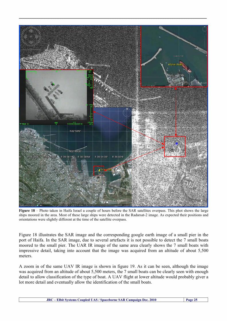
__________________________________________________________________________________
JRC ndash Elbit Systems Coupled UAS Spaceborne SAR Campaign Dec 2010 Page 25
Figure 18 ndash Photo taken in Haifa Israel a couple of hours before the SAR satellites overpass This phot shows the large ships moored in the area Most of these large ships were detected in the Radarsat-2 image As expected their positions and orientations were slightly different at the time of the satellite overpass Figure 18 illustrates the SAR image and the corresponding google earth image of a small pier in the port of Haifa In the SAR image due to several artefacts it is not possible to detect the 7 small boats moored to the small pier The UAR IR image of the same area clearly shows the 7 small boats with impressive detail taking into account that the image was acquired from an altitude of about 5500 meters A zoom in of the same UAV IR image is shown in figure 19 As it can be seen although the image was acquired from an altitude of about 5500 meters the 7 small boats can be clearly seen with enough detail to allow classification of the type of boat A UAV flight at lower altitude would probably giver a lot more detail and eventually allow the identification of the small boats
__________________________________________________________________________________
JRC ndash Elbit Systems Coupled UAS Spaceborne SAR Campaign Dec 2010 Page 26
Figure 19 ndash UAV IR image of a small pier in the port of Haifa Israel where 7 small boats can be seen with enough detail to allow classification This image was acquired from an altitude of about 5500 meters in the dark
__________________________________________________________________________________
55 ndash Quantitative Analysis of the Spaceborne SAR Image In order to allow a quantitative analysis of the data the spaceborne SAR image was calibrated using ESArsquos NEST software package version 4B The input was the SAR image acquired and the output was the Radiometric Calibration (Sigma Naught (σdeg)) expressed in terms of intensity and in decibel (dB) the Radar Brightness (βdeg) and the Radiometric Normalisation (gamma naught (γdeg))
551 ndash Radarsat-2-Spotlight 08Dec2010 (154740 UTC) Haifa Israel Figure 20 illustrates the Intensity band of a subset of the Radarsat-2Spotlgiht image (08Dec2010)
Figure 20 ndash Radarsat-2 Spotlgiht image (08Dec2010) ndash Sigma Naught (Intensity) band
JRC ndash Elbit Systems Coupled UAS Spaceborne SAR Campaign Dec 2010 Page 27
__________________________________________________________________________________
Figure 21 illustrates the Sigma Naught Coefficient of the Radarsat-2 Spotlgiht image (08Dec2010) expressed in terms of intensity and decibel (dB)
Figure 21 ndash Radarsat-2 Spotlgiht image (08Dec2010) - On the left the Sigma Naught (σdeg) (intensity) and on the right the Sigma Naught (σdeg) (dB)
ormalisation amma Naught (γdeg)) of the Radarsat-2 Spotlgiht image (08Dec2010) expressed in dB
-2 Spotlgiht image (08Dec2010) - On the left the Beta Naught (βdeg) and on the right the Gamma Naught (γdeg) (dB)
Figure 22 illustrates the Radar Brightness (Beta Naught (βdeg)) and the radiometric n(G
Figure 22 ndash Radarsat
JRC ndash Elbit Systems Coupled UAS Spaceborne SAR Campaign Dec 2010 Page 28
__________________________________________________________________________________ Figure 23 shows the Sigma Naught (σdeg) in dB after some colour manipulation and the histogram of the Sigma Naught (σdeg) image
Figure 23 ndash Radarsat-2 Spotlgiht image (08Dec2010) - On the top left the Sigma Naught (σdeg) after colour manipulation to enhance the targets and on the top right the corresponding histogram On the bottom we can see the histogram of the image
Table 6 gives the statistics of the Sigma Naught (σdeg) Radarsat-2 Spotlgiht image (08Dec2010) The Sigma Naught (σdeg) range from -72897 dB up to 23465 dB The Mean value is -16855 dB the Median is -16594 dB and the standard deviation is 7077 dB
JRC ndash Elbit Systems Coupled UAS Spaceborne SAR Campaign Dec 2010 Page 29
__________________________________________________________________________________
JRC ndash Elbit Systems Coupled UAS Spaceborne SAR Campaign Dec 2010 Page 30
Table 6 ndash Statistics of the Radarsat-2 Spotlgiht image (08Dec2010) (154740 UTC)
Statistics Values Unit Only ROI-Mask pixels considered Number of pixels total Number of considered pixels Ratio of considered pixels
No 322394283 322394283
1000
Minimum Maximum
-728974609375 234655818939209
intensity_db intensity_db
Mean Median Std-Dev Coefficient of Variation
-16855686580177853 -1659462338617847 707796800831575
07888765273432338
intensity_db intensity_db intensity_db intensity_db
Checking the radar backscattering coefficient of some targets (small boat and some large ships) detected in the Radarsat-2 Spotlight image we get values ranging from -0379 dB up to 23455 dB The analysis of the Sigma Naught values (σdeg) of the targets and the area around the targets shows a significant contrast
56 ndash Summary of the Preliminary Analysis of the Spaceborne SAR Image This experiment involved two spaceborne SAR images namely a TerraSAR-X Stripmap and one Radarsat-2 Spotlight The TerraSAR-X image was not delivered by DLR due to technical problems The Elbitrsquos boat deployed during the experiment was detected in the Radarsat-2 Spotlight image Several other targets including a set of large ships were also detected Table 7 summarises the characteristics of the SAR image acquired and the targets detected
Table 7 ndash List of SAR Satellite Images acquired during the experiment and detected boats ISRAEL (HAIFA)
Date Time Place Satellite Mode Ground Truth Data Detected Boats
08Dec2010 (PM) Haifa - Israel Radarsat-2 Spotlight GPSPhotosMovies 1 small boat deployed + 9 large ships
Table 8 gives the minimum and maximum Sigma Naught (σdeg) of the targets detected in each SAR image
Table 8 ndash Minimum and maximum Sigma Naught (σdeg) of the targets detected in each SAR image
Date Time UTC (LT)Pass Satellite Image Mode Polarisation Sigma Naught (σdeg) Min Max
29Oct2010528UTC(728AM LT) DES Radarsat-2 Spotlight HH --0379 dB 23455 dB The SAR signatures of the boats deployed were very weak Some possible reasons to explain such weak signatures are the sea state the wind speed the incidence angle and the type and materials Another possible reason is the processing at DLR
__________________________________________________________________________________
JRC ndash Elbit Systems Coupled UAS Spaceborne SAR Campaign Dec 2010 Page 31
6 ndash Preliminary Conclusions The analysis of the results of this coupled UASSpaceborne SAR experiment shows a promising potential for the use of UAS for maritime surveillance UAS can be integrated into the airborne building block of maritime surveillance systems to complement the existing assets increase system performance and improve the overall maritime domain awareness The main perceived maritime security and safety threats comprise piracy terrorist and military threats weapons proliferationsmuggling drugs trafficking illegal immigration unlawful use of containers attacks to critical infrastructures and illegal fishing The main maritime security and safety gaps include a lack of technologies with the capability of detecting small targets (eg small boats) a lack of wide area and persistent maritime surveillance a lack of coordination and information sharing limited interoperability a lack of containers security a lack of persistent surveillance of critical infrastructures and early warning systems Unmanned Aircraft Systems (UAS) are an emerging technology with strong potential to mitigate the above mentioned threats by filing in the main maritime security and safety gaps listed earlier For instance the wide range of potential applications of UAS to maritime surveillance includes but is not limited to
bull detection classification and identification of small boats bull persistent maritime surveillance bull use as communications relays bull persistent surveillance of critical infrastructures bull early warning systems bull COMINT and ELINT collection etc
Table 11 illustrates the mapping of maritime securitysafety threats vs gaps and summarises the main potential applications of UAS to maritime surveillance The above mentioned potential applications of UAS to the Maritime Domain will be addressed in turn in more detail next bull Detection classification and identification of small boats ndash The capability of detecting classifying and identifying small targets (eg small boats) is among the key technologies required to improve maritime domain awareness This capability is critical to mitigate piracy illegal immigration drugs trafficking weapons smuggling illegal fishing terrorism and critical infrastructure Unmanned Aircraft Systems (UAS) provide this capability more efficiently and at a lower cost than any other existing technology bull Persistent maritime surveillance ndash With the continuous improvements of UAS technologies such as platforms sensors collision avoidance systems command and control systems telecommunications etc UAS are increasing their autonomy endurance and flexibility These characteristics are very important for persistent maritime surveillance UAS can be launched from land ships aircraft and technologies to launch UAS from submarines are currently under development UAS have distinct advantages over other existing technologies for persistent maritime surveillance in terms of autonomyendurance (the Global Surveyor has an autonomy of 1 week) cost (eg as the autonomy of UAS increases the number of staff required to operate UAS decreases) risk (eg if the UAS crashes the crew is not at risk) flexibility (eg they can be launched from a ship reducing the time to reach potential threats) etc
__________________________________________________________________________________
JRC ndash Elbit Systems Coupled UAS Spaceborne SAR Campaign Dec 2010 Page 32
bull Communications relays ndash UAS are being used as communication relays mainly in military context but have the potential to play a similar role in Civil context in several situations such as to replace satellite communications or as a redundant system over any location on Earth The main advantages of using UAS as communication relays is that airborne communication relays mitigate kinetic and noise jamming threats to satellite communications uplinks by providing an alternative set of links either directly to surface-based terminals or to satellites beyond the range of threats They are less susceptible to noise jamming threats than satellites because an adversary has to detect geolocate and track the airborne asset and operate within line of sight of the receive antenna main beam bull Persistent surveillance of critical infrastructures ndash The security of critical infrastructures such as nuclear power plants refineries ports etc requires persistent surveillance UAS can play an important role in providing persistent surveillance over critical infrastructures and over a wide area around the critical infrastructure Some advantages of UAS over other existing technologies such as ground-based assets (eg video cameras alarm systems manned aircraft etc) comprise the security of the UAS (eg hardly can be damaged or switched off as any ground-based asset) the area covered by a UAS (eg it is larger than the area covered by any ground-based asset) the cost (eg UAS is cheaper than manned aircraft with similar capability) etc bull Early warning systems ndash UAS have the potential to be used as part of an integrated system of systems for early warning A UAS can provide information about a given area at a fraction of the cost of alternative means Formation flying of UAS can cover a wide maritime area It is reasonable to assume that in a foreseeable future with the advent of UAS with increased autonomy the operations cost of UAS will likely decrease making them increasingly more attractive bull COMINT and ELINT collection ndash SIGNal INTelligence (SIGNINT) can be divided into two categories namely COMINT and ELINT COMINT stands for Communication Intelligence and ELINT for Electronic Intelligence Collection of COMINT is passive Exploitation of COMINT requires a human operator which implies COMINT UAS are suitable for COMINT and ELINT collection in different scenarios The relatively reduced amount of data collected and analysed during this experiment and the lessons learned do not allow drawing final conclusions about the feasibility of using Unmanned Aerial Systems (UAS) for maritime surveillance However this experiment allowed hands-on experience with UAS technologies and significantly improved the awareness for its applications to maritime surveillance and related issues involved including its potential the feasibility as well as the limiting and enabling factors These different aspects will now be analysed in turn in the next sections Table 11 illustrates the mapping of the main maritime security threats and gaps as well as the main priorities in terms of the different technologies involved in maritime surveillance For each maritime threat the technologies required to fill in each gap is indicated and its priority is expressed in a range of numbers (1 to 3 1 = Maximum Priority 2 = Medium Priority 3 = Low Priority) and colours (Red = Maximum Priority Orange = Medium Priority Green = Low Priority) The main technologies involved in maritime surveillance are listed on the bottom of figure 4 and are reproduced here for convenience of the reader 1- Reporting Systems 2- Sensors 3- Platforms 4- Communications 5- Data Fusion amp Sharing 6- Intelligence and 7- Databases For example the mitigation of the main threat Piracy requires filling in several maritime security gaps (eg lack of persistent surveillance lack of wide-are maritime surveillance lack of small boat detection lack of Early Warning Systems and lack of Information Sharing with maximum priority (1- Red) and among the required technologies listed are UAS LTAAV GEO-HR etc Concerning the remaining two gaps (Limited Interoperability and Containers Security) they are less relevant to mitigate Piracy hence the priority for Limited Interoperability is 2-Orange and for Containers Security is 3- Green
__________________________________________________________________________________ Table 9 ndash The Main Maritime Security and Safety Threats vs Gaps and the technologies that can be used to mitigate them
Maritime Security Main Threats GapsGapsrarr
darrThreats
Lack o f Risk As sessmentCapab ility
La ck of Persiste nt
Surveilla nce
La ck of Wid e-Area su rve illanc e
La ck of Small Boat De tecti on
Lack o f Earl y Warn ing Sys tems
L ack of In forma tion
Sh arin g
L imi ted In terop era bility
Lac k of Co ntai ners
Se cur ity
bull PiracyUAS LTAVG EO-
HR + UAS LT AVGEO-
HR + SAR GEO-HR
+ UAS USV LTAV
+ UAS LTAV
+ Coord in ationamp Sharing +
Inter opera bilityOptimisation +
1 2 3 5 6 7 1 2 3 5 6 7 1 2 3 5 6 1 2 3 123456 4567 1234567 1234567
bull Terro rismUAS LTAVG EO-
HR + UAS L TAV GEO-HR +
SAR AISGEO-HR +
UAS USV LTAV+
Intelligence+
Inte lligen ce+
Inter opera bilityOptimisation +
Intelligence+
1 2 3 5 6 7 1 2 3 5 6 1 2 3 5 6 1 2 3 123456 4567 1234567 1234567
bull Wea pon s ofM ass Dest ru ctio n Smugg ling
UAS LTAVG EO-HR +
UAS LT AVGEO-HR +
SAR AIS+
UAS USV LTAV+
Intelligence+
Inte lligen ce+
Intelligence+
Intelligence+
1 2 3 5 6 7 1 2 3 5 6 1 2 3 5 6 1 2 3 123456 4567 1234567 1234567
bull Drug sTraffic king
UAS LTAVG EO-HR +
UAS LT AVGEO-HR +
SAR AIS+
UAS USV LTAV+
Intelligence+
Inte lligen ce+
Intelligence+
Intelligence+
1 2 3 5 6 7 1 2 3 5 6 1 2 3 5 6 1 2 3 123456 4567 1234567 1234567
bull Illega lImmigratio n
UAS LTAVG EO-HR +
UAS LT AVGEO-HR +
SAR AIS+
UAS USV LTAV+
Intelligence+
Inte lligen ce+
Intelligence+
Intelligence+
1 2 3 5 6 7 1 2 3 5 6 1 2 3 5 6 1 2 3 123456 4567 1234567 1234567
bull Critic alI nfrastruc tureSecu rit y
UAS LTAVG EO-HR +
UAS LT AVGEO-HR +
SAR AIS+
UAS USV LTAV+ + Inte lligen ce
+ Intelligence
+ Intelligence
+
1 2 3 5 6 7 1 2 3 6 1 2 3 5 6 1 2 3 123456 4567 1234567 1234567
bull Illega lFish ing
UAS LTAVG EO-HR +
AI S+SAR UASLTAV +
SAR AIS GEO-HR+
UAS USV LTAV+
Intelligence+
Inte lligen ce+
Intelligence+
1 2 3 5 6 7 1 2 3 5 7 1 2 3 5 6 1 2 3 123456 4567 1234567
bull Un lawf ul Use of Co nta iners
(Secur ity)
UAS LTAVG EO-HR +
GPS Tr acking+
Intelligence+
Inte lligen ce+
GPS Int rusion Det ection Se al
1 2 3 5 6 7 4 6 7 1 2 3 5 6 1 2 3 123456 4567 1234567 1234567
(-) Priority (+) Not Rel evant
SURVEILLANCETECHNOLOGIES
1- Reporti ng Systems
2 -Sensors 3 -P latforms 4 - Communications 5- Data Fusionamp Sharing
6 -I ntelli gence 7 -Databases
JRC ndash Elbit Systems Coupled UAS Spaceborne SAR Campaign Dec 2010 Page 33
__________________________________________________________________________________
JRC ndash Elbit Systems Coupled UAS Spaceborne SAR Campaign Dec 2010 Page 34
61 ndash Hands-on experience with UAS technologies and its applications to maritime surveillance This coupled UASSpaceborne SAR campaign was a unique opportunity to acquire further handsndashon experience with UAS technologies and learn about the main issues related to its applications to maritime surveillance From the planning phase up to the execution of the UAS flight and landing there are several factors that need to be carefully analysed and taken into account A summary of the main issues identified in this experiment is given next 1- Selection of the Experiment Area Authorisation to Fly ndash For the time being UAS can only be flown in restricted areas usually under control of national authorities often the military This is due to the risks that a UAS can pose to human life and property In the present case an area under the authority of the Israeli Civil Aviation Authority was selected The authorisation to fly was not easy to obtain because the selected area is under the authority of the Civil Aviation Authority Figure 24 indicates the area of the experiment in Haifa Israel 2- UAS Communications Issues ndash The Hermes 450 was flown in Line-of-Sight (LOS) since it was close to the coast For BLOS (Beyond Line-of-Sight) operation satellite communications are required 3- Synthetic Aperture Radar (SAR) ndash The specific model Hermes 450W used in the experiment had no SAR sensor installed However a SAR sensor can be installed A SAR sensor is important for maritime surveillance since it allows 247 operations regardless of the weather conditions 4- Automatic Identification System (AIS) Receiver ndash The Hermes 450 used in this experiment was not equipped with an AIS receiver For maritime surveillance operations an AIS receiver is a very important tool since it allows the automatic identification of most ships allowing the UAS to concentrate on non-identified ships
__________________________________________________________________________________
Figure 24 ndash The area of the experiment is indicated by the GPS Trajectory of the UAV
62 ndash Potential of UAS for Maritime Surveillance UAS technologies are relatively recent and involve a wide range of fields spanning from aeronautics and sensors technologies to satellite communications and other engineering disciplines Innovations in each of the fields involved are emerging by the day UAS still have a long way to go before they become mature and their use fully operational For the time being UAS are mainly used for military applications However a large number of non-military UAS applications have been identified by stakeholders and there are several studies and demonstration flights foreseen for the near future Maritime surveillance is one of the most challenging and promising fields of application of UAS The challenges are due to the very demanding conditions under which the UAS must operate over sea and the requirements for safe operation
JRC ndash Elbit Systems Coupled UAS Spaceborne SAR Campaign Dec 2010 Page 35
__________________________________________________________________________________
JRC ndash Elbit Systems Coupled UAS Spaceborne SAR Campaign Dec 2010 Page 36
The present UAS experiment has unveiled some of the potential of UAS for maritime surveillance The UAS tests performed during this experiment include
1 ndash Detection of a Small rubber Boat and a Fishing Ship 2 ndash Tracking of a Small Boat and a Fishing Ship 3 ndash Classification of a Small Boat and a Fishing Ship 4 ndash Identification of a Small Boat and a Fishing Ship 5 ndash Detection and Tracking of People on the Beach
Despite the operational requirement that prevented the UAS from flying bellow 3km the experiment has confirmed the capability of UAS for small boat detection tracking and classification as well as the capability for people detection and tracking Concerning the identification of the targets the characteristics of the images acquired during this mission suggest that flying at lower altitudes the UAS images would allow the identification of the targets The UAS images can be seen from Figure 15 to 20
621 ndash Advantages of UAS for maritime Surveillance Some of the advantages of using UAS for maritime surveillance have been described in the literature and are summarized bellow
1- One potential benefit of UAS is that they could fill in a gap in current maritime surveillance by improving coverage
2- The range of UAS is a significant asset when compared to border agents on patrol or stationary surveillance equipment
3- Eletro-Optical InfraRed (EOIR) sensors (cameras) can identify small size objects from very high altitudes (high resolution)
4- UAS can provide precise and near-real-time imagery to a ground control operator who would then disseminate that information so that informed decisions regarding the deployment of border patrol agents can be made quickly
5- Long endurance UAS used along the border can fly for more than 30 hours up to several days without having to refuel compared with manned helicopterrsquos average flight time of just over 2 hours
6- The ability of UAS to loiter for prolonged periods of time has important operational advantages over manned aircraft
7- The longer flight times of UAS means that sustained coverage over a previously exposed area may improve maritime security
8- The range of UAVs is a significant asset when compared to border agents on patrol or stationary surveillance equipment Nevertheless the extended range and endurance of UAVs may lessen the burdens on human resources at the borders
9- UAS accidents do not risk the lives of pilots as do the helicopters and aircraft currently used by Coast Guards for border patrolling
__________________________________________________________________________________
JRC ndash Elbit Systems Coupled UAS Spaceborne SAR Campaign Dec 2010 Page 37
622 ndash Possible Drawbacks of using UAS for maritime Surveillance UAS also have disadvantages some of them are briefly described next
1- There have been concerns regarding the high accident rate of UAS which can be multiple times higher than that of manned aircraft Because UAS technology is still evolving there is less redundancy built into the operating system of UAS than of manned aircraft and until redundant systems are perfected mishap rates are expected to remain high
2- If control systems fail in a manned aircraft a well-trained pilot is better positioned to find the source of the problem because of hisher physical proximity If a UAS encountered a similar system failure or if a UAS landing was attempted during difficult weather conditions the ground control pilot would be at a disadvantage because he or she is removed from the event Unlike a manned pilot the remote pilot would not be able to assess important sensory information such as wind speed
3- Inclement weather conditions can also impinge on a UAS surveillance capability especially UAS equipped with only an EO camera and Forward Looking Infrared Radar (FLIR) because cloudy conditions and high humidity climates can distort the imagery produced by EO and FLIR equipment The effects of extreme climatic or atmospheric conditions on sensors reportedly can be mitigated with the outfit of one synthetic aperture radar (SAR) system and a moving target indicator (MTI) radar However adding SAR and MTI to a UAS platform would increase the costs associated with using UAS
4- Depending on the type of UAS the costs of operating a UAS can be higher than the costs of operating a manned aircraft This is because some types of UAS require a significant amount of logistical support and specialized operator and maintenance training Operating one UAS may require a crew of up to 20 support personnel The high comparative costs of operating some sophisticated types of UAS may be offset somewhat by their comparatively lower unit costs
63 ndash Main Limiting Factors Preventing the Use of UAS Several pre-requisites must be satisfied to render the UAS a viable cost-effective and regulated alternative to existing resources Major civil and commercial market barriers include
Single European Sky Sense and Avoid technologies Command and Control Technologies Reliability Communications (Bandwidth LOS BLOS)
Lack of airspace regulation that covers all types of UAV systems (encompassing lsquosense and avoidrsquo airspace integration and airworthiness issues)
Affordability - price and customization issues (eg commercial off-the-shelf open modular architecture) Lack of efforts to establish joint customer requirements (although this is gradually changing) Liability for civil operation Capacity for payload flexibility Lack of sufficient secure non-military frequencies for civil operation Perceived reliability (eg vehicle attrition rate vs manned aircraft) Operator training issues Recognitioncustomer perception of the UAV market Technology developments for multi-mission capability
__________________________________________________________________________________
64 ndash UAS Key Enabling Technologies Figure 25 illustrates the components of a typical UAV System showing some of the capabilities needed and the enabling technologies required for performing a given mission Any UAV mission involves many capabilities and technologies Due to the depicted system complexity the main key players such as the US Department of Defense (DoD) and other agencies have started to use the term Unmanned Aerial System (UAS) in place of UAV
Figure 25 ndash Unmanned Aerial Vehicle System Enabled by Autonomous Mission Management Reliable Flight Systems Navigation Accurate Systems Terrain Avoidance Power and Propulsion Some UAS key enabling technologies are listed below
Autonomous Mission Management Collision Avoidance Intelligent System Health Monitoring
Reliable Flight Systems Sophisticated Contingency Management Intelligent Data Handling and Processing Over-the-Horizon Communication Network-Centric Communication Open Architecture Power and Propulsion Navigation Accurate System Technology Enhanced Structures
JRC ndash Elbit Systems Coupled UAS Spaceborne SAR Campaign Dec 2010 Page 38
__________________________________________________________________________________
JRC ndash Elbit Systems Coupled UAS Spaceborne SAR Campaign Dec 2010 Page 39
Table 12 gives a more detailed description of other critical technologies for emerging autonomous UAV systems both civil and military Most of the technologies mentioned in Table 12 apply both to civil and military UAV systems Table 10 ndash Key Enabling Technologies (from SG75 study on autonomous systems)
Critical Technologies Decision Making Software
bull Fuzzy-based decision making bull Knowledge-based system bull Case-based reasoning bull Self-learning techniques bull Decision tree evaluation bull ReasoningInferring bull Probabilisticstochastic reasoning
Prediction Algorithms bull Predictive pathintent algorithms bull Short reaction algorithm bull Effectiveness evaluation
Status Assessment Software bull Internal status analysis bull Self-orientation
Situation Analysis Software bull Situation analysis bull Environmental analysis bull External status analysis
Modelling Software bull Air vehicle modelling algorithms bull Sensor modelling algorithms bull Scenario generation bull Threat system modeling bull Attack simulation bull Mission success optimisation model bull Simulation
Sensor Processing Software bull Sensor fusion bull Area of interest identification bull Automatic target recognition
Adaptive and Self-learning Systems bull Failure self-compensation
Attack Planning Software bull Attack plans and tactical alternatives bull Plan change impact identification
Weapon Engagement Procedure Software bull Weapon engagement algorithms
Mission Plan Update Software bull Route planning system bull Payload plan management system bull Mission Success Optimisation model
Path Optimisation Software bull Optimal trajectory planning bull Path Optimisation System
Targeting Software bull Target tracking bull Target prioritisation
Platform Technologies bull Obstacle detection and avoidance (airborne) bull Obstacle detection and avoidance (ground) bull Improved autopilot bull Speech recognition
Figure 26 summarises system element designs needed to transition from current to next-generation autonomous UAV systems for civilian and military UAS
__________________________________________________________________________________
Figure 26 ndash System Element Designs Needed to Transition from Current to Next-Generation Autonomous UAV Systems These new paradigms are a combination of system attributes and technological capabilities For instance the data fusion secure anti-jam and coordinated multi-vehicle control require technological development as well as specific system development to bring full maturity to unmanned systems Finally very small Micro UAVs (MAVs) and relatively large sophisticated UCAV systems are examples of the range of UAVs that are applying the new platforms payloads onboard processing communications etc to create next generation automated UAVs It is with these new platforms payloads etc that both UCAVs and MAV will be able to address similar operational challenges including
Mixed operation with other assets bull Deconfliction collision avoidance C4I integration
Operation over populated areas bull Safety issues Need to reduce reliance on communications bull UCAV ndash countermeasures bull MAV ndash limited size and power bull Limited line of sight environment Need a fully integrated system bull MAV propulsionpower generation still critical bull Operator machine interface critical bull All weather operations bull Survivability
JRC ndash Elbit Systems Coupled UAS Spaceborne SAR Campaign Dec 2010 Page 40
__________________________________________________________________________________
JRC ndash Elbit Systems Coupled UAS Spaceborne SAR Campaign Dec 2010 Page 41
65 ndash Mission Readiness
651 ndash Mission Readiness Summary This section summarises civil UAV mission readiness The purpose of Mission Readiness is to assess the readiness status of the different technologies involved in UAS In the present case this civil UAV mission readiness based on technology maturation forecasts that meet or exceed the desired or required capabilities identified by the user community Figure 27 summarises the mission readiness time forecasts for the different technologies The technologies annotated with an asterisk () are shown within the figure with maturation forecasts based on development targets expressed in the US Department of Defencesrsquo UAV Roadmap document The purpose of the chart is to be able to identify when the capability to fly a particular mission can be expected as a function of time The left-most end is the least probable and the right end the most probable timeframe
Figure 27 ndash Technology Maturation Summaries in Terms of Mission-Derived Capabilities
__________________________________________________________________________________
JRC ndash Elbit Systems Coupled UAS Spaceborne SAR Campaign Dec 2010 Page 42
66 ndash Small Boat Detection in SAR Satellite Imagery The use of spaceborne SAR imagery for small boat detection requires additional small boat detection experiments under different conditions using different methods It is not possible to draw final conclusions based on a limited number of small boat detection experiments which are not representative of the multiple possible scenarios
67 ndash Limitations of current State-of-the-Art SAR Satellite technology The main limitations of current State-of-the-Art spaceborne SAR imagery for maritime surveillance in particular aimed at small boat detection are 1 - SAR satellites repeat cycles do not allow the coverage of the same area at the required time intervals Constellations of SAR satellites could be a solution 2 - The conflict between resolution and image swath High resolution is required to detect small boats However the high resolution images have small swaths Maritime surveillance with high resolution images would require a large number of images to cover wide maritime areas which is very expensive and for the time being technically not feasible Intelligence data can play an important role by indicating an approximate position of suspicious non cooperative targets therefore reducing the surveillance area which can then be imaged using high resolution images 3- Spaceborne high resolution SAR imagery acquisition times are long enough to allow significant motion of the target during the acquisition time degrading the quality of the image Further research efforts are needed to develop new sensors and platforms As far as sensors are concerned shorter integration times are needed to prevent the blurring effect caused by the motion of the targets Regarding the platforms more platforms are needed to allow lower repeat cycles and improved coverage
__________________________________________________________________________________
JRC ndash Elbit Systems Coupled UAS Spaceborne SAR Campaign Dec 2010 Page 43
7 ndash Plans for Future Work The controlled experiments carried out by the EC-JRC together with Elbit Systems in Haifa-Israel comprised the deployment of a UAS (Hermes-450) and one small 12-meter boat A Radarsat-2 Spotlight image was acquired and several images collected by the Hermes-450 The experiment unveiled the potential of UAS for maritime surveillance in particular for detection tracking classification and possible identification of small targets The UAS was able to detect track and classify small targets such as small boats For low UAS altitude flights identification may be possible in some cases The small 12-meter boat was detected in the spaceborne SAR image The small boat detection trials carried out by the JRC were very successful since most small boats deployed during the experiments were detected in different sea states wind speeds and geographical locations The several small boat detection campaigns conducted by the EC-JRC seem to suggest that the probability of detection of small boats in spaceborne SAR images strongly depends on factors such as the sea state the wind speed the type of boat (shape and materials) the weather conditions among other factors The results of the experiments conducted thus far are not enough to draw final conclusions about the feasibility of using spaceborne SAR imagery for small boat detection However the experiments have an overall positive outcome because they indicate that under suitable sea state and wind speed conditions it is possible to detect small boats using spaceborne SAR The estimation of the probability of detection of small boats in spaceborne SAR images requires a large number of experiments under different circumstances (eg sea state wind speed characteristics of the targets image type and mode etc) Future plans include additional UAS experiments to asses its potential for maritime surveillance
Acknowledgements ndash The authors would like to express their gratitude to Elbit Systems for their cooperation logistical support and assets deployed without which the present coupled UASSAR Satellite Small Boat Detection Campaign would have not been possible
__________________________________________________________________________________
JRC ndash Elbit Systems Coupled UAS Spaceborne SAR Campaign Dec 2010 Page 44
REFERENCES [1] Elbit Systems ldquoUAV Elbit Systems Proposal for Unmanned Aerial Vehicle (UAV) flight to
collect Ground Truth data during a Maritime Surveillance Campaign and demonstrate UAV capabilities for Maritime Surveillancerdquo 2010
[2] ndash Cheryl Yuhas Suborbital Science Program Manager NASA Science Mission Directorate ldquoEarth Observations and the Role of UAVs A Capabilities Assessment Version 11rdquo Civil UAV Assessment Team httpwwwnasagovcentersdrydenresearchcivuavindexhtml August 2006
[3] ndash Document NIAG (SG75) NATO Industrial Advisory Group Study Group 75 Pre-Feasibility Study on UAV Autonomous Operations 2004
[4] ndash United States Department of Defence (DoD) Directive 50001 ldquoThe Defense Acquisition Systemrdquo and DoD Instruction 50002 ldquoOperation of the Defense Acquisition Systemrdquo
[5] ndash Mr James Ramage Mr Massimo Avalle Dr Erik Berglund Dr Luigi Crovella Mr Robert Frampton Dr Uwe Krogmann Mr Christian Ravat Mr Mike Robinson Dr Axel Schulte Dr Scott Wood ldquoRTO-TR-SCI-118 - Automation Technologies and Application Considerations for Highly Integrated Mission Systemsrdquo RTO-TR-SCI-118 AC323(SCI-118)TP204 January 2009
[6] Victor MG Silva Gilles Jurquet Gabriel Marchalot Maria TG Calzado Txema Soroa Juan Sancho Adam Koubek Harm Greidanus and Claudio Savarino ldquoWide Maritime Area Airborne Surveillance (WIMA2S) WP5 Final Reportrdquo WIMAAS WP5 FP7 Project 2008-2011 - ISBN-978-92-79-22801-8 (print) 978-92-79-22802-5 (PDF) ISSN-1018-5593 (print) 1831-9424 (online) EC-JRC Scientific Report JRC 70093 2012
[7] Victor MG Silva and Harm Greidanus ldquoSpaceborne SAR Small Boat Detection Campaign in Portugal and Spainrdquo EUR 25281 EN ISBN 978-92-79-22553-6 ISSN 1831-9424 (online) EC-JRC Scientific Report JRC68160 2012
[8] Goncalves Da Silva V Van Wimersma Greidanus H Hejmanowska B Loudjani P ldquoUAS Applications With Societal Benefits ndash JRCrsquos UAS-Related Activitiesrdquo 2011-2012 UAS Yearbook - UAS Unmanned Aircraft Systems - The Global Perspective 9 (9) 2011 p 127-129 JRC66600
[9] Goncalves Da Silva V Van Wimersma Greidanus H ldquoSmall boat detection using TerraSAR-X and Radarsat2 satellite imageryrdquo 4th TerraSAR-X Science Team Meeting 14 February 2011 DLR Oberpfaffenhofen (Germany) German Aerospace Center (DLR) (Organiser) 2011 JRC63663
[10] V Silva Harm Greidanus ldquoJRC - SAR Satellite Small Boat Detection Campaign - Portoroz ndash Sloveniardquo - ISBN-13 978-92-79-21476-9 ISSN (online) 1831-9424 EC-JRC Scientific Report JRC66835 2011
[11] V Silva Harm Greidanus ldquoJRC - SAR satellite small boat detection campaign - Algarve Portugalrdquo - ISBN-13 978-92-79-21265-9 ISSN (online) 1831-9424 ISSN (print) 1018-5593 EC-JRC Scientific Report JRC66631 2011
[12] ndash Goncalves Da Silva V Van Wimersma Greidanus H ldquoJRC-Frontex Spaceborne SAR Small Boat Detection Campaign ndash Italy amp Spainrdquo - ISBN-13 978-92-79-22213-9 ISSN (online) 1831-9424 EC-JRC Scientific Report JRC67517 2011
[13] - PW Vachon SJ Thomas J Cranton HR Edel and MD Henschel Validation of ship detection by the RADARSAT synthetic aperture radar and the Ocean Monitoring Workstation Canadian Journal of Remote Sensing 26(3)200ndash212 2000
[14] - Crisp D (2004) The state-of-the-art in ship detection in Synthetic Aperture Radar imagery DSTO Information Sciences Laboratory Australia
[15] - Joint Research Centre (JRC) of the European Community mdash IMPAST and DECLIMS web site httpintelligencejrcceceuintmarinefishindexhtm
[16] - McCandless SW Jackson CR (2004) Principles of Synthetic Aperture Radar Synthetic Aperture Radar Marine Users Manual NOAA Washington pp 1-23
[17] - Greidanus H (2008) Satellite Imaging for Maritime Surveillance of the European Seas Remote Sensing of the European Seas 343-358
European Commission
EUR 25346 EN --- Joint Research Centre --- Institute for the Protection and Security of the Citizen
Title JRC --- Elbit Systems Coupled UAS and Spaceborne SAR Campaign in Israel
Authors Victor MG Silva Harm Greidanus
Luxembourg Publications Office of the European Union
2012 --- v+44 pp --- 210 x 297 cm
EUR --- Scientific and Technical Research series --- ISSN 181-9424 (online) ISSN 1018-5593 (print)
ISBN 978-92-79-25020-0
doi10278828527
Abstract The European maritime area is one of Europersquos most important assets with regard to resources security and ultimately
prosperity of the Member States A significant part of Europersquos economy relies directly or indirectly on it It is not just the
shipping or fisheries industries and their related activities It is also shipbuilding and ports marine equipment and offshore
energy maritime and coastal tourism aquaculture submarine telecommunications blue biotech and the protection of the
marine environment The European maritime area faces several risks and threats posed by unlawful activities such as drugs
trafficking smuggling illegal immigration organised crime and terrorism Piracy in international waters also constitutes a threat
to Europe since it can disrupt the maritime transport chain These risks and threats can endanger human lives marine resources
and the environment as well as significantly disrupt the transport chain and global and local security It is anticipated that these
risks and threats will endure in the mid and long run In order to keep Europe as a world leader in the global maritime economy
an effective integratedinteroperable sustainable maritime surveillance system and situational awareness are needed
A significant number of unlawful maritime activities such as illegal immigration drugs trafficking smuggling piracy and
terrorism involve mainly small boats because small boats are faster and more difficult to detect using conventional means
Hence it is very important to find out the feasibility of using Unmanned Aerial Systems (UAS) for small boat detection tracking
classification and identification as well as to study the potential of UAS for maritime surveillance Since 2010 the EC-JRC has
carried out a number of UAS maritime surveillance campaigns to study the potential of UAS for maritime surveillance in
particular for small boat detection This report presents the results and conclusions of the JRC --- Elbit Systems Coupled UAS and
Spaceborne SAR campaign carried out in Dec 2010 in Haifa Israel
As the Commissionrsquos in-house science service the Joint Research Centrersquos mission is to provide EU policies with independent evidence-based scientific and technical support throughout the whole policy cycle Working in close cooperation with policy Directorates-General the JRC addresses key societal challenges while stimulating innovation through developing new standards methods and tools and sharing and transferring its know-how to the Member States and international community Key policy areas include environment and climate change energy and transport agriculture and food security health and consumer protection information society and digital agenda safety and security including nuclear all supported through a cross-cutting and multi-disciplinary approach
LB-NA-25346-EN
-N
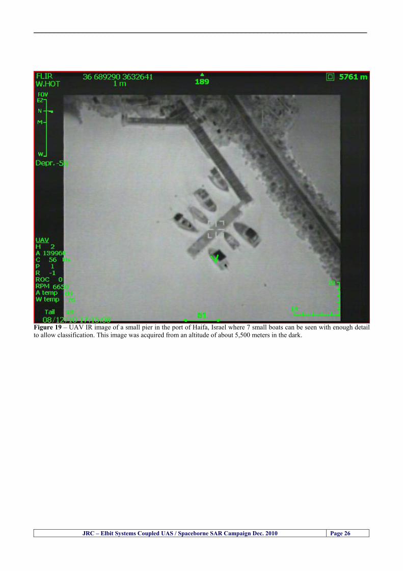
__________________________________________________________________________________
JRC ndash Elbit Systems Coupled UAS Spaceborne SAR Campaign Dec 2010 Page 26
Figure 19 ndash UAV IR image of a small pier in the port of Haifa Israel where 7 small boats can be seen with enough detail to allow classification This image was acquired from an altitude of about 5500 meters in the dark
__________________________________________________________________________________
55 ndash Quantitative Analysis of the Spaceborne SAR Image In order to allow a quantitative analysis of the data the spaceborne SAR image was calibrated using ESArsquos NEST software package version 4B The input was the SAR image acquired and the output was the Radiometric Calibration (Sigma Naught (σdeg)) expressed in terms of intensity and in decibel (dB) the Radar Brightness (βdeg) and the Radiometric Normalisation (gamma naught (γdeg))
551 ndash Radarsat-2-Spotlight 08Dec2010 (154740 UTC) Haifa Israel Figure 20 illustrates the Intensity band of a subset of the Radarsat-2Spotlgiht image (08Dec2010)
Figure 20 ndash Radarsat-2 Spotlgiht image (08Dec2010) ndash Sigma Naught (Intensity) band
JRC ndash Elbit Systems Coupled UAS Spaceborne SAR Campaign Dec 2010 Page 27
__________________________________________________________________________________
Figure 21 illustrates the Sigma Naught Coefficient of the Radarsat-2 Spotlgiht image (08Dec2010) expressed in terms of intensity and decibel (dB)
Figure 21 ndash Radarsat-2 Spotlgiht image (08Dec2010) - On the left the Sigma Naught (σdeg) (intensity) and on the right the Sigma Naught (σdeg) (dB)
ormalisation amma Naught (γdeg)) of the Radarsat-2 Spotlgiht image (08Dec2010) expressed in dB
-2 Spotlgiht image (08Dec2010) - On the left the Beta Naught (βdeg) and on the right the Gamma Naught (γdeg) (dB)
Figure 22 illustrates the Radar Brightness (Beta Naught (βdeg)) and the radiometric n(G
Figure 22 ndash Radarsat
JRC ndash Elbit Systems Coupled UAS Spaceborne SAR Campaign Dec 2010 Page 28
__________________________________________________________________________________ Figure 23 shows the Sigma Naught (σdeg) in dB after some colour manipulation and the histogram of the Sigma Naught (σdeg) image
Figure 23 ndash Radarsat-2 Spotlgiht image (08Dec2010) - On the top left the Sigma Naught (σdeg) after colour manipulation to enhance the targets and on the top right the corresponding histogram On the bottom we can see the histogram of the image
Table 6 gives the statistics of the Sigma Naught (σdeg) Radarsat-2 Spotlgiht image (08Dec2010) The Sigma Naught (σdeg) range from -72897 dB up to 23465 dB The Mean value is -16855 dB the Median is -16594 dB and the standard deviation is 7077 dB
JRC ndash Elbit Systems Coupled UAS Spaceborne SAR Campaign Dec 2010 Page 29
__________________________________________________________________________________
JRC ndash Elbit Systems Coupled UAS Spaceborne SAR Campaign Dec 2010 Page 30
Table 6 ndash Statistics of the Radarsat-2 Spotlgiht image (08Dec2010) (154740 UTC)
Statistics Values Unit Only ROI-Mask pixels considered Number of pixels total Number of considered pixels Ratio of considered pixels
No 322394283 322394283
1000
Minimum Maximum
-728974609375 234655818939209
intensity_db intensity_db
Mean Median Std-Dev Coefficient of Variation
-16855686580177853 -1659462338617847 707796800831575
07888765273432338
intensity_db intensity_db intensity_db intensity_db
Checking the radar backscattering coefficient of some targets (small boat and some large ships) detected in the Radarsat-2 Spotlight image we get values ranging from -0379 dB up to 23455 dB The analysis of the Sigma Naught values (σdeg) of the targets and the area around the targets shows a significant contrast
56 ndash Summary of the Preliminary Analysis of the Spaceborne SAR Image This experiment involved two spaceborne SAR images namely a TerraSAR-X Stripmap and one Radarsat-2 Spotlight The TerraSAR-X image was not delivered by DLR due to technical problems The Elbitrsquos boat deployed during the experiment was detected in the Radarsat-2 Spotlight image Several other targets including a set of large ships were also detected Table 7 summarises the characteristics of the SAR image acquired and the targets detected
Table 7 ndash List of SAR Satellite Images acquired during the experiment and detected boats ISRAEL (HAIFA)
Date Time Place Satellite Mode Ground Truth Data Detected Boats
08Dec2010 (PM) Haifa - Israel Radarsat-2 Spotlight GPSPhotosMovies 1 small boat deployed + 9 large ships
Table 8 gives the minimum and maximum Sigma Naught (σdeg) of the targets detected in each SAR image
Table 8 ndash Minimum and maximum Sigma Naught (σdeg) of the targets detected in each SAR image
Date Time UTC (LT)Pass Satellite Image Mode Polarisation Sigma Naught (σdeg) Min Max
29Oct2010528UTC(728AM LT) DES Radarsat-2 Spotlight HH --0379 dB 23455 dB The SAR signatures of the boats deployed were very weak Some possible reasons to explain such weak signatures are the sea state the wind speed the incidence angle and the type and materials Another possible reason is the processing at DLR
__________________________________________________________________________________
JRC ndash Elbit Systems Coupled UAS Spaceborne SAR Campaign Dec 2010 Page 31
6 ndash Preliminary Conclusions The analysis of the results of this coupled UASSpaceborne SAR experiment shows a promising potential for the use of UAS for maritime surveillance UAS can be integrated into the airborne building block of maritime surveillance systems to complement the existing assets increase system performance and improve the overall maritime domain awareness The main perceived maritime security and safety threats comprise piracy terrorist and military threats weapons proliferationsmuggling drugs trafficking illegal immigration unlawful use of containers attacks to critical infrastructures and illegal fishing The main maritime security and safety gaps include a lack of technologies with the capability of detecting small targets (eg small boats) a lack of wide area and persistent maritime surveillance a lack of coordination and information sharing limited interoperability a lack of containers security a lack of persistent surveillance of critical infrastructures and early warning systems Unmanned Aircraft Systems (UAS) are an emerging technology with strong potential to mitigate the above mentioned threats by filing in the main maritime security and safety gaps listed earlier For instance the wide range of potential applications of UAS to maritime surveillance includes but is not limited to
bull detection classification and identification of small boats bull persistent maritime surveillance bull use as communications relays bull persistent surveillance of critical infrastructures bull early warning systems bull COMINT and ELINT collection etc
Table 11 illustrates the mapping of maritime securitysafety threats vs gaps and summarises the main potential applications of UAS to maritime surveillance The above mentioned potential applications of UAS to the Maritime Domain will be addressed in turn in more detail next bull Detection classification and identification of small boats ndash The capability of detecting classifying and identifying small targets (eg small boats) is among the key technologies required to improve maritime domain awareness This capability is critical to mitigate piracy illegal immigration drugs trafficking weapons smuggling illegal fishing terrorism and critical infrastructure Unmanned Aircraft Systems (UAS) provide this capability more efficiently and at a lower cost than any other existing technology bull Persistent maritime surveillance ndash With the continuous improvements of UAS technologies such as platforms sensors collision avoidance systems command and control systems telecommunications etc UAS are increasing their autonomy endurance and flexibility These characteristics are very important for persistent maritime surveillance UAS can be launched from land ships aircraft and technologies to launch UAS from submarines are currently under development UAS have distinct advantages over other existing technologies for persistent maritime surveillance in terms of autonomyendurance (the Global Surveyor has an autonomy of 1 week) cost (eg as the autonomy of UAS increases the number of staff required to operate UAS decreases) risk (eg if the UAS crashes the crew is not at risk) flexibility (eg they can be launched from a ship reducing the time to reach potential threats) etc
__________________________________________________________________________________
JRC ndash Elbit Systems Coupled UAS Spaceborne SAR Campaign Dec 2010 Page 32
bull Communications relays ndash UAS are being used as communication relays mainly in military context but have the potential to play a similar role in Civil context in several situations such as to replace satellite communications or as a redundant system over any location on Earth The main advantages of using UAS as communication relays is that airborne communication relays mitigate kinetic and noise jamming threats to satellite communications uplinks by providing an alternative set of links either directly to surface-based terminals or to satellites beyond the range of threats They are less susceptible to noise jamming threats than satellites because an adversary has to detect geolocate and track the airborne asset and operate within line of sight of the receive antenna main beam bull Persistent surveillance of critical infrastructures ndash The security of critical infrastructures such as nuclear power plants refineries ports etc requires persistent surveillance UAS can play an important role in providing persistent surveillance over critical infrastructures and over a wide area around the critical infrastructure Some advantages of UAS over other existing technologies such as ground-based assets (eg video cameras alarm systems manned aircraft etc) comprise the security of the UAS (eg hardly can be damaged or switched off as any ground-based asset) the area covered by a UAS (eg it is larger than the area covered by any ground-based asset) the cost (eg UAS is cheaper than manned aircraft with similar capability) etc bull Early warning systems ndash UAS have the potential to be used as part of an integrated system of systems for early warning A UAS can provide information about a given area at a fraction of the cost of alternative means Formation flying of UAS can cover a wide maritime area It is reasonable to assume that in a foreseeable future with the advent of UAS with increased autonomy the operations cost of UAS will likely decrease making them increasingly more attractive bull COMINT and ELINT collection ndash SIGNal INTelligence (SIGNINT) can be divided into two categories namely COMINT and ELINT COMINT stands for Communication Intelligence and ELINT for Electronic Intelligence Collection of COMINT is passive Exploitation of COMINT requires a human operator which implies COMINT UAS are suitable for COMINT and ELINT collection in different scenarios The relatively reduced amount of data collected and analysed during this experiment and the lessons learned do not allow drawing final conclusions about the feasibility of using Unmanned Aerial Systems (UAS) for maritime surveillance However this experiment allowed hands-on experience with UAS technologies and significantly improved the awareness for its applications to maritime surveillance and related issues involved including its potential the feasibility as well as the limiting and enabling factors These different aspects will now be analysed in turn in the next sections Table 11 illustrates the mapping of the main maritime security threats and gaps as well as the main priorities in terms of the different technologies involved in maritime surveillance For each maritime threat the technologies required to fill in each gap is indicated and its priority is expressed in a range of numbers (1 to 3 1 = Maximum Priority 2 = Medium Priority 3 = Low Priority) and colours (Red = Maximum Priority Orange = Medium Priority Green = Low Priority) The main technologies involved in maritime surveillance are listed on the bottom of figure 4 and are reproduced here for convenience of the reader 1- Reporting Systems 2- Sensors 3- Platforms 4- Communications 5- Data Fusion amp Sharing 6- Intelligence and 7- Databases For example the mitigation of the main threat Piracy requires filling in several maritime security gaps (eg lack of persistent surveillance lack of wide-are maritime surveillance lack of small boat detection lack of Early Warning Systems and lack of Information Sharing with maximum priority (1- Red) and among the required technologies listed are UAS LTAAV GEO-HR etc Concerning the remaining two gaps (Limited Interoperability and Containers Security) they are less relevant to mitigate Piracy hence the priority for Limited Interoperability is 2-Orange and for Containers Security is 3- Green
__________________________________________________________________________________ Table 9 ndash The Main Maritime Security and Safety Threats vs Gaps and the technologies that can be used to mitigate them
Maritime Security Main Threats GapsGapsrarr
darrThreats
Lack o f Risk As sessmentCapab ility
La ck of Persiste nt
Surveilla nce
La ck of Wid e-Area su rve illanc e
La ck of Small Boat De tecti on
Lack o f Earl y Warn ing Sys tems
L ack of In forma tion
Sh arin g
L imi ted In terop era bility
Lac k of Co ntai ners
Se cur ity
bull PiracyUAS LTAVG EO-
HR + UAS LT AVGEO-
HR + SAR GEO-HR
+ UAS USV LTAV
+ UAS LTAV
+ Coord in ationamp Sharing +
Inter opera bilityOptimisation +
1 2 3 5 6 7 1 2 3 5 6 7 1 2 3 5 6 1 2 3 123456 4567 1234567 1234567
bull Terro rismUAS LTAVG EO-
HR + UAS L TAV GEO-HR +
SAR AISGEO-HR +
UAS USV LTAV+
Intelligence+
Inte lligen ce+
Inter opera bilityOptimisation +
Intelligence+
1 2 3 5 6 7 1 2 3 5 6 1 2 3 5 6 1 2 3 123456 4567 1234567 1234567
bull Wea pon s ofM ass Dest ru ctio n Smugg ling
UAS LTAVG EO-HR +
UAS LT AVGEO-HR +
SAR AIS+
UAS USV LTAV+
Intelligence+
Inte lligen ce+
Intelligence+
Intelligence+
1 2 3 5 6 7 1 2 3 5 6 1 2 3 5 6 1 2 3 123456 4567 1234567 1234567
bull Drug sTraffic king
UAS LTAVG EO-HR +
UAS LT AVGEO-HR +
SAR AIS+
UAS USV LTAV+
Intelligence+
Inte lligen ce+
Intelligence+
Intelligence+
1 2 3 5 6 7 1 2 3 5 6 1 2 3 5 6 1 2 3 123456 4567 1234567 1234567
bull Illega lImmigratio n
UAS LTAVG EO-HR +
UAS LT AVGEO-HR +
SAR AIS+
UAS USV LTAV+
Intelligence+
Inte lligen ce+
Intelligence+
Intelligence+
1 2 3 5 6 7 1 2 3 5 6 1 2 3 5 6 1 2 3 123456 4567 1234567 1234567
bull Critic alI nfrastruc tureSecu rit y
UAS LTAVG EO-HR +
UAS LT AVGEO-HR +
SAR AIS+
UAS USV LTAV+ + Inte lligen ce
+ Intelligence
+ Intelligence
+
1 2 3 5 6 7 1 2 3 6 1 2 3 5 6 1 2 3 123456 4567 1234567 1234567
bull Illega lFish ing
UAS LTAVG EO-HR +
AI S+SAR UASLTAV +
SAR AIS GEO-HR+
UAS USV LTAV+
Intelligence+
Inte lligen ce+
Intelligence+
1 2 3 5 6 7 1 2 3 5 7 1 2 3 5 6 1 2 3 123456 4567 1234567
bull Un lawf ul Use of Co nta iners
(Secur ity)
UAS LTAVG EO-HR +
GPS Tr acking+
Intelligence+
Inte lligen ce+
GPS Int rusion Det ection Se al
1 2 3 5 6 7 4 6 7 1 2 3 5 6 1 2 3 123456 4567 1234567 1234567
(-) Priority (+) Not Rel evant
SURVEILLANCETECHNOLOGIES
1- Reporti ng Systems
2 -Sensors 3 -P latforms 4 - Communications 5- Data Fusionamp Sharing
6 -I ntelli gence 7 -Databases
JRC ndash Elbit Systems Coupled UAS Spaceborne SAR Campaign Dec 2010 Page 33
__________________________________________________________________________________
JRC ndash Elbit Systems Coupled UAS Spaceborne SAR Campaign Dec 2010 Page 34
61 ndash Hands-on experience with UAS technologies and its applications to maritime surveillance This coupled UASSpaceborne SAR campaign was a unique opportunity to acquire further handsndashon experience with UAS technologies and learn about the main issues related to its applications to maritime surveillance From the planning phase up to the execution of the UAS flight and landing there are several factors that need to be carefully analysed and taken into account A summary of the main issues identified in this experiment is given next 1- Selection of the Experiment Area Authorisation to Fly ndash For the time being UAS can only be flown in restricted areas usually under control of national authorities often the military This is due to the risks that a UAS can pose to human life and property In the present case an area under the authority of the Israeli Civil Aviation Authority was selected The authorisation to fly was not easy to obtain because the selected area is under the authority of the Civil Aviation Authority Figure 24 indicates the area of the experiment in Haifa Israel 2- UAS Communications Issues ndash The Hermes 450 was flown in Line-of-Sight (LOS) since it was close to the coast For BLOS (Beyond Line-of-Sight) operation satellite communications are required 3- Synthetic Aperture Radar (SAR) ndash The specific model Hermes 450W used in the experiment had no SAR sensor installed However a SAR sensor can be installed A SAR sensor is important for maritime surveillance since it allows 247 operations regardless of the weather conditions 4- Automatic Identification System (AIS) Receiver ndash The Hermes 450 used in this experiment was not equipped with an AIS receiver For maritime surveillance operations an AIS receiver is a very important tool since it allows the automatic identification of most ships allowing the UAS to concentrate on non-identified ships
__________________________________________________________________________________
Figure 24 ndash The area of the experiment is indicated by the GPS Trajectory of the UAV
62 ndash Potential of UAS for Maritime Surveillance UAS technologies are relatively recent and involve a wide range of fields spanning from aeronautics and sensors technologies to satellite communications and other engineering disciplines Innovations in each of the fields involved are emerging by the day UAS still have a long way to go before they become mature and their use fully operational For the time being UAS are mainly used for military applications However a large number of non-military UAS applications have been identified by stakeholders and there are several studies and demonstration flights foreseen for the near future Maritime surveillance is one of the most challenging and promising fields of application of UAS The challenges are due to the very demanding conditions under which the UAS must operate over sea and the requirements for safe operation
JRC ndash Elbit Systems Coupled UAS Spaceborne SAR Campaign Dec 2010 Page 35
__________________________________________________________________________________
JRC ndash Elbit Systems Coupled UAS Spaceborne SAR Campaign Dec 2010 Page 36
The present UAS experiment has unveiled some of the potential of UAS for maritime surveillance The UAS tests performed during this experiment include
1 ndash Detection of a Small rubber Boat and a Fishing Ship 2 ndash Tracking of a Small Boat and a Fishing Ship 3 ndash Classification of a Small Boat and a Fishing Ship 4 ndash Identification of a Small Boat and a Fishing Ship 5 ndash Detection and Tracking of People on the Beach
Despite the operational requirement that prevented the UAS from flying bellow 3km the experiment has confirmed the capability of UAS for small boat detection tracking and classification as well as the capability for people detection and tracking Concerning the identification of the targets the characteristics of the images acquired during this mission suggest that flying at lower altitudes the UAS images would allow the identification of the targets The UAS images can be seen from Figure 15 to 20
621 ndash Advantages of UAS for maritime Surveillance Some of the advantages of using UAS for maritime surveillance have been described in the literature and are summarized bellow
1- One potential benefit of UAS is that they could fill in a gap in current maritime surveillance by improving coverage
2- The range of UAS is a significant asset when compared to border agents on patrol or stationary surveillance equipment
3- Eletro-Optical InfraRed (EOIR) sensors (cameras) can identify small size objects from very high altitudes (high resolution)
4- UAS can provide precise and near-real-time imagery to a ground control operator who would then disseminate that information so that informed decisions regarding the deployment of border patrol agents can be made quickly
5- Long endurance UAS used along the border can fly for more than 30 hours up to several days without having to refuel compared with manned helicopterrsquos average flight time of just over 2 hours
6- The ability of UAS to loiter for prolonged periods of time has important operational advantages over manned aircraft
7- The longer flight times of UAS means that sustained coverage over a previously exposed area may improve maritime security
8- The range of UAVs is a significant asset when compared to border agents on patrol or stationary surveillance equipment Nevertheless the extended range and endurance of UAVs may lessen the burdens on human resources at the borders
9- UAS accidents do not risk the lives of pilots as do the helicopters and aircraft currently used by Coast Guards for border patrolling
__________________________________________________________________________________
JRC ndash Elbit Systems Coupled UAS Spaceborne SAR Campaign Dec 2010 Page 37
622 ndash Possible Drawbacks of using UAS for maritime Surveillance UAS also have disadvantages some of them are briefly described next
1- There have been concerns regarding the high accident rate of UAS which can be multiple times higher than that of manned aircraft Because UAS technology is still evolving there is less redundancy built into the operating system of UAS than of manned aircraft and until redundant systems are perfected mishap rates are expected to remain high
2- If control systems fail in a manned aircraft a well-trained pilot is better positioned to find the source of the problem because of hisher physical proximity If a UAS encountered a similar system failure or if a UAS landing was attempted during difficult weather conditions the ground control pilot would be at a disadvantage because he or she is removed from the event Unlike a manned pilot the remote pilot would not be able to assess important sensory information such as wind speed
3- Inclement weather conditions can also impinge on a UAS surveillance capability especially UAS equipped with only an EO camera and Forward Looking Infrared Radar (FLIR) because cloudy conditions and high humidity climates can distort the imagery produced by EO and FLIR equipment The effects of extreme climatic or atmospheric conditions on sensors reportedly can be mitigated with the outfit of one synthetic aperture radar (SAR) system and a moving target indicator (MTI) radar However adding SAR and MTI to a UAS platform would increase the costs associated with using UAS
4- Depending on the type of UAS the costs of operating a UAS can be higher than the costs of operating a manned aircraft This is because some types of UAS require a significant amount of logistical support and specialized operator and maintenance training Operating one UAS may require a crew of up to 20 support personnel The high comparative costs of operating some sophisticated types of UAS may be offset somewhat by their comparatively lower unit costs
63 ndash Main Limiting Factors Preventing the Use of UAS Several pre-requisites must be satisfied to render the UAS a viable cost-effective and regulated alternative to existing resources Major civil and commercial market barriers include
Single European Sky Sense and Avoid technologies Command and Control Technologies Reliability Communications (Bandwidth LOS BLOS)
Lack of airspace regulation that covers all types of UAV systems (encompassing lsquosense and avoidrsquo airspace integration and airworthiness issues)
Affordability - price and customization issues (eg commercial off-the-shelf open modular architecture) Lack of efforts to establish joint customer requirements (although this is gradually changing) Liability for civil operation Capacity for payload flexibility Lack of sufficient secure non-military frequencies for civil operation Perceived reliability (eg vehicle attrition rate vs manned aircraft) Operator training issues Recognitioncustomer perception of the UAV market Technology developments for multi-mission capability
__________________________________________________________________________________
64 ndash UAS Key Enabling Technologies Figure 25 illustrates the components of a typical UAV System showing some of the capabilities needed and the enabling technologies required for performing a given mission Any UAV mission involves many capabilities and technologies Due to the depicted system complexity the main key players such as the US Department of Defense (DoD) and other agencies have started to use the term Unmanned Aerial System (UAS) in place of UAV
Figure 25 ndash Unmanned Aerial Vehicle System Enabled by Autonomous Mission Management Reliable Flight Systems Navigation Accurate Systems Terrain Avoidance Power and Propulsion Some UAS key enabling technologies are listed below
Autonomous Mission Management Collision Avoidance Intelligent System Health Monitoring
Reliable Flight Systems Sophisticated Contingency Management Intelligent Data Handling and Processing Over-the-Horizon Communication Network-Centric Communication Open Architecture Power and Propulsion Navigation Accurate System Technology Enhanced Structures
JRC ndash Elbit Systems Coupled UAS Spaceborne SAR Campaign Dec 2010 Page 38
__________________________________________________________________________________
JRC ndash Elbit Systems Coupled UAS Spaceborne SAR Campaign Dec 2010 Page 39
Table 12 gives a more detailed description of other critical technologies for emerging autonomous UAV systems both civil and military Most of the technologies mentioned in Table 12 apply both to civil and military UAV systems Table 10 ndash Key Enabling Technologies (from SG75 study on autonomous systems)
Critical Technologies Decision Making Software
bull Fuzzy-based decision making bull Knowledge-based system bull Case-based reasoning bull Self-learning techniques bull Decision tree evaluation bull ReasoningInferring bull Probabilisticstochastic reasoning
Prediction Algorithms bull Predictive pathintent algorithms bull Short reaction algorithm bull Effectiveness evaluation
Status Assessment Software bull Internal status analysis bull Self-orientation
Situation Analysis Software bull Situation analysis bull Environmental analysis bull External status analysis
Modelling Software bull Air vehicle modelling algorithms bull Sensor modelling algorithms bull Scenario generation bull Threat system modeling bull Attack simulation bull Mission success optimisation model bull Simulation
Sensor Processing Software bull Sensor fusion bull Area of interest identification bull Automatic target recognition
Adaptive and Self-learning Systems bull Failure self-compensation
Attack Planning Software bull Attack plans and tactical alternatives bull Plan change impact identification
Weapon Engagement Procedure Software bull Weapon engagement algorithms
Mission Plan Update Software bull Route planning system bull Payload plan management system bull Mission Success Optimisation model
Path Optimisation Software bull Optimal trajectory planning bull Path Optimisation System
Targeting Software bull Target tracking bull Target prioritisation
Platform Technologies bull Obstacle detection and avoidance (airborne) bull Obstacle detection and avoidance (ground) bull Improved autopilot bull Speech recognition
Figure 26 summarises system element designs needed to transition from current to next-generation autonomous UAV systems for civilian and military UAS
__________________________________________________________________________________
Figure 26 ndash System Element Designs Needed to Transition from Current to Next-Generation Autonomous UAV Systems These new paradigms are a combination of system attributes and technological capabilities For instance the data fusion secure anti-jam and coordinated multi-vehicle control require technological development as well as specific system development to bring full maturity to unmanned systems Finally very small Micro UAVs (MAVs) and relatively large sophisticated UCAV systems are examples of the range of UAVs that are applying the new platforms payloads onboard processing communications etc to create next generation automated UAVs It is with these new platforms payloads etc that both UCAVs and MAV will be able to address similar operational challenges including
Mixed operation with other assets bull Deconfliction collision avoidance C4I integration
Operation over populated areas bull Safety issues Need to reduce reliance on communications bull UCAV ndash countermeasures bull MAV ndash limited size and power bull Limited line of sight environment Need a fully integrated system bull MAV propulsionpower generation still critical bull Operator machine interface critical bull All weather operations bull Survivability
JRC ndash Elbit Systems Coupled UAS Spaceborne SAR Campaign Dec 2010 Page 40
__________________________________________________________________________________
JRC ndash Elbit Systems Coupled UAS Spaceborne SAR Campaign Dec 2010 Page 41
65 ndash Mission Readiness
651 ndash Mission Readiness Summary This section summarises civil UAV mission readiness The purpose of Mission Readiness is to assess the readiness status of the different technologies involved in UAS In the present case this civil UAV mission readiness based on technology maturation forecasts that meet or exceed the desired or required capabilities identified by the user community Figure 27 summarises the mission readiness time forecasts for the different technologies The technologies annotated with an asterisk () are shown within the figure with maturation forecasts based on development targets expressed in the US Department of Defencesrsquo UAV Roadmap document The purpose of the chart is to be able to identify when the capability to fly a particular mission can be expected as a function of time The left-most end is the least probable and the right end the most probable timeframe
Figure 27 ndash Technology Maturation Summaries in Terms of Mission-Derived Capabilities
__________________________________________________________________________________
JRC ndash Elbit Systems Coupled UAS Spaceborne SAR Campaign Dec 2010 Page 42
66 ndash Small Boat Detection in SAR Satellite Imagery The use of spaceborne SAR imagery for small boat detection requires additional small boat detection experiments under different conditions using different methods It is not possible to draw final conclusions based on a limited number of small boat detection experiments which are not representative of the multiple possible scenarios
67 ndash Limitations of current State-of-the-Art SAR Satellite technology The main limitations of current State-of-the-Art spaceborne SAR imagery for maritime surveillance in particular aimed at small boat detection are 1 - SAR satellites repeat cycles do not allow the coverage of the same area at the required time intervals Constellations of SAR satellites could be a solution 2 - The conflict between resolution and image swath High resolution is required to detect small boats However the high resolution images have small swaths Maritime surveillance with high resolution images would require a large number of images to cover wide maritime areas which is very expensive and for the time being technically not feasible Intelligence data can play an important role by indicating an approximate position of suspicious non cooperative targets therefore reducing the surveillance area which can then be imaged using high resolution images 3- Spaceborne high resolution SAR imagery acquisition times are long enough to allow significant motion of the target during the acquisition time degrading the quality of the image Further research efforts are needed to develop new sensors and platforms As far as sensors are concerned shorter integration times are needed to prevent the blurring effect caused by the motion of the targets Regarding the platforms more platforms are needed to allow lower repeat cycles and improved coverage
__________________________________________________________________________________
JRC ndash Elbit Systems Coupled UAS Spaceborne SAR Campaign Dec 2010 Page 43
7 ndash Plans for Future Work The controlled experiments carried out by the EC-JRC together with Elbit Systems in Haifa-Israel comprised the deployment of a UAS (Hermes-450) and one small 12-meter boat A Radarsat-2 Spotlight image was acquired and several images collected by the Hermes-450 The experiment unveiled the potential of UAS for maritime surveillance in particular for detection tracking classification and possible identification of small targets The UAS was able to detect track and classify small targets such as small boats For low UAS altitude flights identification may be possible in some cases The small 12-meter boat was detected in the spaceborne SAR image The small boat detection trials carried out by the JRC were very successful since most small boats deployed during the experiments were detected in different sea states wind speeds and geographical locations The several small boat detection campaigns conducted by the EC-JRC seem to suggest that the probability of detection of small boats in spaceborne SAR images strongly depends on factors such as the sea state the wind speed the type of boat (shape and materials) the weather conditions among other factors The results of the experiments conducted thus far are not enough to draw final conclusions about the feasibility of using spaceborne SAR imagery for small boat detection However the experiments have an overall positive outcome because they indicate that under suitable sea state and wind speed conditions it is possible to detect small boats using spaceborne SAR The estimation of the probability of detection of small boats in spaceborne SAR images requires a large number of experiments under different circumstances (eg sea state wind speed characteristics of the targets image type and mode etc) Future plans include additional UAS experiments to asses its potential for maritime surveillance
Acknowledgements ndash The authors would like to express their gratitude to Elbit Systems for their cooperation logistical support and assets deployed without which the present coupled UASSAR Satellite Small Boat Detection Campaign would have not been possible
__________________________________________________________________________________
JRC ndash Elbit Systems Coupled UAS Spaceborne SAR Campaign Dec 2010 Page 44
REFERENCES [1] Elbit Systems ldquoUAV Elbit Systems Proposal for Unmanned Aerial Vehicle (UAV) flight to
collect Ground Truth data during a Maritime Surveillance Campaign and demonstrate UAV capabilities for Maritime Surveillancerdquo 2010
[2] ndash Cheryl Yuhas Suborbital Science Program Manager NASA Science Mission Directorate ldquoEarth Observations and the Role of UAVs A Capabilities Assessment Version 11rdquo Civil UAV Assessment Team httpwwwnasagovcentersdrydenresearchcivuavindexhtml August 2006
[3] ndash Document NIAG (SG75) NATO Industrial Advisory Group Study Group 75 Pre-Feasibility Study on UAV Autonomous Operations 2004
[4] ndash United States Department of Defence (DoD) Directive 50001 ldquoThe Defense Acquisition Systemrdquo and DoD Instruction 50002 ldquoOperation of the Defense Acquisition Systemrdquo
[5] ndash Mr James Ramage Mr Massimo Avalle Dr Erik Berglund Dr Luigi Crovella Mr Robert Frampton Dr Uwe Krogmann Mr Christian Ravat Mr Mike Robinson Dr Axel Schulte Dr Scott Wood ldquoRTO-TR-SCI-118 - Automation Technologies and Application Considerations for Highly Integrated Mission Systemsrdquo RTO-TR-SCI-118 AC323(SCI-118)TP204 January 2009
[6] Victor MG Silva Gilles Jurquet Gabriel Marchalot Maria TG Calzado Txema Soroa Juan Sancho Adam Koubek Harm Greidanus and Claudio Savarino ldquoWide Maritime Area Airborne Surveillance (WIMA2S) WP5 Final Reportrdquo WIMAAS WP5 FP7 Project 2008-2011 - ISBN-978-92-79-22801-8 (print) 978-92-79-22802-5 (PDF) ISSN-1018-5593 (print) 1831-9424 (online) EC-JRC Scientific Report JRC 70093 2012
[7] Victor MG Silva and Harm Greidanus ldquoSpaceborne SAR Small Boat Detection Campaign in Portugal and Spainrdquo EUR 25281 EN ISBN 978-92-79-22553-6 ISSN 1831-9424 (online) EC-JRC Scientific Report JRC68160 2012
[8] Goncalves Da Silva V Van Wimersma Greidanus H Hejmanowska B Loudjani P ldquoUAS Applications With Societal Benefits ndash JRCrsquos UAS-Related Activitiesrdquo 2011-2012 UAS Yearbook - UAS Unmanned Aircraft Systems - The Global Perspective 9 (9) 2011 p 127-129 JRC66600
[9] Goncalves Da Silva V Van Wimersma Greidanus H ldquoSmall boat detection using TerraSAR-X and Radarsat2 satellite imageryrdquo 4th TerraSAR-X Science Team Meeting 14 February 2011 DLR Oberpfaffenhofen (Germany) German Aerospace Center (DLR) (Organiser) 2011 JRC63663
[10] V Silva Harm Greidanus ldquoJRC - SAR Satellite Small Boat Detection Campaign - Portoroz ndash Sloveniardquo - ISBN-13 978-92-79-21476-9 ISSN (online) 1831-9424 EC-JRC Scientific Report JRC66835 2011
[11] V Silva Harm Greidanus ldquoJRC - SAR satellite small boat detection campaign - Algarve Portugalrdquo - ISBN-13 978-92-79-21265-9 ISSN (online) 1831-9424 ISSN (print) 1018-5593 EC-JRC Scientific Report JRC66631 2011
[12] ndash Goncalves Da Silva V Van Wimersma Greidanus H ldquoJRC-Frontex Spaceborne SAR Small Boat Detection Campaign ndash Italy amp Spainrdquo - ISBN-13 978-92-79-22213-9 ISSN (online) 1831-9424 EC-JRC Scientific Report JRC67517 2011
[13] - PW Vachon SJ Thomas J Cranton HR Edel and MD Henschel Validation of ship detection by the RADARSAT synthetic aperture radar and the Ocean Monitoring Workstation Canadian Journal of Remote Sensing 26(3)200ndash212 2000
[14] - Crisp D (2004) The state-of-the-art in ship detection in Synthetic Aperture Radar imagery DSTO Information Sciences Laboratory Australia
[15] - Joint Research Centre (JRC) of the European Community mdash IMPAST and DECLIMS web site httpintelligencejrcceceuintmarinefishindexhtm
[16] - McCandless SW Jackson CR (2004) Principles of Synthetic Aperture Radar Synthetic Aperture Radar Marine Users Manual NOAA Washington pp 1-23
[17] - Greidanus H (2008) Satellite Imaging for Maritime Surveillance of the European Seas Remote Sensing of the European Seas 343-358
European Commission
EUR 25346 EN --- Joint Research Centre --- Institute for the Protection and Security of the Citizen
Title JRC --- Elbit Systems Coupled UAS and Spaceborne SAR Campaign in Israel
Authors Victor MG Silva Harm Greidanus
Luxembourg Publications Office of the European Union
2012 --- v+44 pp --- 210 x 297 cm
EUR --- Scientific and Technical Research series --- ISSN 181-9424 (online) ISSN 1018-5593 (print)
ISBN 978-92-79-25020-0
doi10278828527
Abstract The European maritime area is one of Europersquos most important assets with regard to resources security and ultimately
prosperity of the Member States A significant part of Europersquos economy relies directly or indirectly on it It is not just the
shipping or fisheries industries and their related activities It is also shipbuilding and ports marine equipment and offshore
energy maritime and coastal tourism aquaculture submarine telecommunications blue biotech and the protection of the
marine environment The European maritime area faces several risks and threats posed by unlawful activities such as drugs
trafficking smuggling illegal immigration organised crime and terrorism Piracy in international waters also constitutes a threat
to Europe since it can disrupt the maritime transport chain These risks and threats can endanger human lives marine resources
and the environment as well as significantly disrupt the transport chain and global and local security It is anticipated that these
risks and threats will endure in the mid and long run In order to keep Europe as a world leader in the global maritime economy
an effective integratedinteroperable sustainable maritime surveillance system and situational awareness are needed
A significant number of unlawful maritime activities such as illegal immigration drugs trafficking smuggling piracy and
terrorism involve mainly small boats because small boats are faster and more difficult to detect using conventional means
Hence it is very important to find out the feasibility of using Unmanned Aerial Systems (UAS) for small boat detection tracking
classification and identification as well as to study the potential of UAS for maritime surveillance Since 2010 the EC-JRC has
carried out a number of UAS maritime surveillance campaigns to study the potential of UAS for maritime surveillance in
particular for small boat detection This report presents the results and conclusions of the JRC --- Elbit Systems Coupled UAS and
Spaceborne SAR campaign carried out in Dec 2010 in Haifa Israel
As the Commissionrsquos in-house science service the Joint Research Centrersquos mission is to provide EU policies with independent evidence-based scientific and technical support throughout the whole policy cycle Working in close cooperation with policy Directorates-General the JRC addresses key societal challenges while stimulating innovation through developing new standards methods and tools and sharing and transferring its know-how to the Member States and international community Key policy areas include environment and climate change energy and transport agriculture and food security health and consumer protection information society and digital agenda safety and security including nuclear all supported through a cross-cutting and multi-disciplinary approach
LB-NA-25346-EN
-N
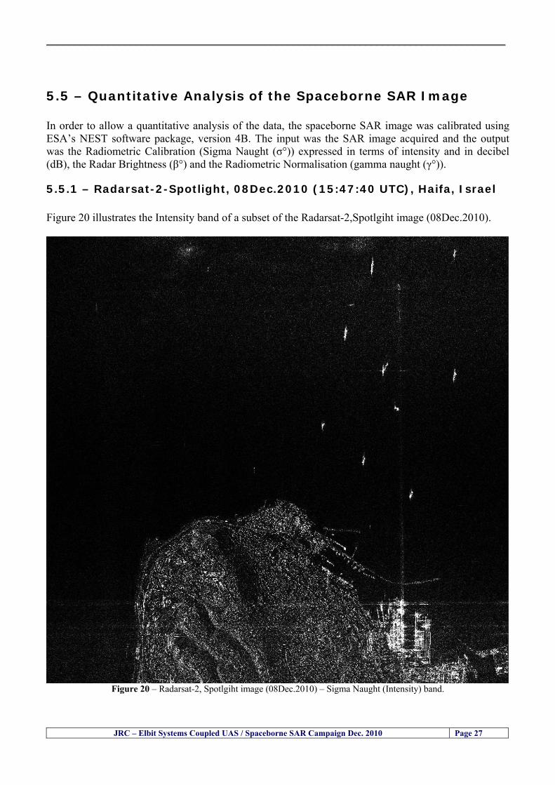
__________________________________________________________________________________
55 ndash Quantitative Analysis of the Spaceborne SAR Image In order to allow a quantitative analysis of the data the spaceborne SAR image was calibrated using ESArsquos NEST software package version 4B The input was the SAR image acquired and the output was the Radiometric Calibration (Sigma Naught (σdeg)) expressed in terms of intensity and in decibel (dB) the Radar Brightness (βdeg) and the Radiometric Normalisation (gamma naught (γdeg))
551 ndash Radarsat-2-Spotlight 08Dec2010 (154740 UTC) Haifa Israel Figure 20 illustrates the Intensity band of a subset of the Radarsat-2Spotlgiht image (08Dec2010)
Figure 20 ndash Radarsat-2 Spotlgiht image (08Dec2010) ndash Sigma Naught (Intensity) band
JRC ndash Elbit Systems Coupled UAS Spaceborne SAR Campaign Dec 2010 Page 27
__________________________________________________________________________________
Figure 21 illustrates the Sigma Naught Coefficient of the Radarsat-2 Spotlgiht image (08Dec2010) expressed in terms of intensity and decibel (dB)
Figure 21 ndash Radarsat-2 Spotlgiht image (08Dec2010) - On the left the Sigma Naught (σdeg) (intensity) and on the right the Sigma Naught (σdeg) (dB)
ormalisation amma Naught (γdeg)) of the Radarsat-2 Spotlgiht image (08Dec2010) expressed in dB
-2 Spotlgiht image (08Dec2010) - On the left the Beta Naught (βdeg) and on the right the Gamma Naught (γdeg) (dB)
Figure 22 illustrates the Radar Brightness (Beta Naught (βdeg)) and the radiometric n(G
Figure 22 ndash Radarsat
JRC ndash Elbit Systems Coupled UAS Spaceborne SAR Campaign Dec 2010 Page 28
__________________________________________________________________________________ Figure 23 shows the Sigma Naught (σdeg) in dB after some colour manipulation and the histogram of the Sigma Naught (σdeg) image
Figure 23 ndash Radarsat-2 Spotlgiht image (08Dec2010) - On the top left the Sigma Naught (σdeg) after colour manipulation to enhance the targets and on the top right the corresponding histogram On the bottom we can see the histogram of the image
Table 6 gives the statistics of the Sigma Naught (σdeg) Radarsat-2 Spotlgiht image (08Dec2010) The Sigma Naught (σdeg) range from -72897 dB up to 23465 dB The Mean value is -16855 dB the Median is -16594 dB and the standard deviation is 7077 dB
JRC ndash Elbit Systems Coupled UAS Spaceborne SAR Campaign Dec 2010 Page 29
__________________________________________________________________________________
JRC ndash Elbit Systems Coupled UAS Spaceborne SAR Campaign Dec 2010 Page 30
Table 6 ndash Statistics of the Radarsat-2 Spotlgiht image (08Dec2010) (154740 UTC)
Statistics Values Unit Only ROI-Mask pixels considered Number of pixels total Number of considered pixels Ratio of considered pixels
No 322394283 322394283
1000
Minimum Maximum
-728974609375 234655818939209
intensity_db intensity_db
Mean Median Std-Dev Coefficient of Variation
-16855686580177853 -1659462338617847 707796800831575
07888765273432338
intensity_db intensity_db intensity_db intensity_db
Checking the radar backscattering coefficient of some targets (small boat and some large ships) detected in the Radarsat-2 Spotlight image we get values ranging from -0379 dB up to 23455 dB The analysis of the Sigma Naught values (σdeg) of the targets and the area around the targets shows a significant contrast
56 ndash Summary of the Preliminary Analysis of the Spaceborne SAR Image This experiment involved two spaceborne SAR images namely a TerraSAR-X Stripmap and one Radarsat-2 Spotlight The TerraSAR-X image was not delivered by DLR due to technical problems The Elbitrsquos boat deployed during the experiment was detected in the Radarsat-2 Spotlight image Several other targets including a set of large ships were also detected Table 7 summarises the characteristics of the SAR image acquired and the targets detected
Table 7 ndash List of SAR Satellite Images acquired during the experiment and detected boats ISRAEL (HAIFA)
Date Time Place Satellite Mode Ground Truth Data Detected Boats
08Dec2010 (PM) Haifa - Israel Radarsat-2 Spotlight GPSPhotosMovies 1 small boat deployed + 9 large ships
Table 8 gives the minimum and maximum Sigma Naught (σdeg) of the targets detected in each SAR image
Table 8 ndash Minimum and maximum Sigma Naught (σdeg) of the targets detected in each SAR image
Date Time UTC (LT)Pass Satellite Image Mode Polarisation Sigma Naught (σdeg) Min Max
29Oct2010528UTC(728AM LT) DES Radarsat-2 Spotlight HH --0379 dB 23455 dB The SAR signatures of the boats deployed were very weak Some possible reasons to explain such weak signatures are the sea state the wind speed the incidence angle and the type and materials Another possible reason is the processing at DLR
__________________________________________________________________________________
JRC ndash Elbit Systems Coupled UAS Spaceborne SAR Campaign Dec 2010 Page 31
6 ndash Preliminary Conclusions The analysis of the results of this coupled UASSpaceborne SAR experiment shows a promising potential for the use of UAS for maritime surveillance UAS can be integrated into the airborne building block of maritime surveillance systems to complement the existing assets increase system performance and improve the overall maritime domain awareness The main perceived maritime security and safety threats comprise piracy terrorist and military threats weapons proliferationsmuggling drugs trafficking illegal immigration unlawful use of containers attacks to critical infrastructures and illegal fishing The main maritime security and safety gaps include a lack of technologies with the capability of detecting small targets (eg small boats) a lack of wide area and persistent maritime surveillance a lack of coordination and information sharing limited interoperability a lack of containers security a lack of persistent surveillance of critical infrastructures and early warning systems Unmanned Aircraft Systems (UAS) are an emerging technology with strong potential to mitigate the above mentioned threats by filing in the main maritime security and safety gaps listed earlier For instance the wide range of potential applications of UAS to maritime surveillance includes but is not limited to
bull detection classification and identification of small boats bull persistent maritime surveillance bull use as communications relays bull persistent surveillance of critical infrastructures bull early warning systems bull COMINT and ELINT collection etc
Table 11 illustrates the mapping of maritime securitysafety threats vs gaps and summarises the main potential applications of UAS to maritime surveillance The above mentioned potential applications of UAS to the Maritime Domain will be addressed in turn in more detail next bull Detection classification and identification of small boats ndash The capability of detecting classifying and identifying small targets (eg small boats) is among the key technologies required to improve maritime domain awareness This capability is critical to mitigate piracy illegal immigration drugs trafficking weapons smuggling illegal fishing terrorism and critical infrastructure Unmanned Aircraft Systems (UAS) provide this capability more efficiently and at a lower cost than any other existing technology bull Persistent maritime surveillance ndash With the continuous improvements of UAS technologies such as platforms sensors collision avoidance systems command and control systems telecommunications etc UAS are increasing their autonomy endurance and flexibility These characteristics are very important for persistent maritime surveillance UAS can be launched from land ships aircraft and technologies to launch UAS from submarines are currently under development UAS have distinct advantages over other existing technologies for persistent maritime surveillance in terms of autonomyendurance (the Global Surveyor has an autonomy of 1 week) cost (eg as the autonomy of UAS increases the number of staff required to operate UAS decreases) risk (eg if the UAS crashes the crew is not at risk) flexibility (eg they can be launched from a ship reducing the time to reach potential threats) etc
__________________________________________________________________________________
JRC ndash Elbit Systems Coupled UAS Spaceborne SAR Campaign Dec 2010 Page 32
bull Communications relays ndash UAS are being used as communication relays mainly in military context but have the potential to play a similar role in Civil context in several situations such as to replace satellite communications or as a redundant system over any location on Earth The main advantages of using UAS as communication relays is that airborne communication relays mitigate kinetic and noise jamming threats to satellite communications uplinks by providing an alternative set of links either directly to surface-based terminals or to satellites beyond the range of threats They are less susceptible to noise jamming threats than satellites because an adversary has to detect geolocate and track the airborne asset and operate within line of sight of the receive antenna main beam bull Persistent surveillance of critical infrastructures ndash The security of critical infrastructures such as nuclear power plants refineries ports etc requires persistent surveillance UAS can play an important role in providing persistent surveillance over critical infrastructures and over a wide area around the critical infrastructure Some advantages of UAS over other existing technologies such as ground-based assets (eg video cameras alarm systems manned aircraft etc) comprise the security of the UAS (eg hardly can be damaged or switched off as any ground-based asset) the area covered by a UAS (eg it is larger than the area covered by any ground-based asset) the cost (eg UAS is cheaper than manned aircraft with similar capability) etc bull Early warning systems ndash UAS have the potential to be used as part of an integrated system of systems for early warning A UAS can provide information about a given area at a fraction of the cost of alternative means Formation flying of UAS can cover a wide maritime area It is reasonable to assume that in a foreseeable future with the advent of UAS with increased autonomy the operations cost of UAS will likely decrease making them increasingly more attractive bull COMINT and ELINT collection ndash SIGNal INTelligence (SIGNINT) can be divided into two categories namely COMINT and ELINT COMINT stands for Communication Intelligence and ELINT for Electronic Intelligence Collection of COMINT is passive Exploitation of COMINT requires a human operator which implies COMINT UAS are suitable for COMINT and ELINT collection in different scenarios The relatively reduced amount of data collected and analysed during this experiment and the lessons learned do not allow drawing final conclusions about the feasibility of using Unmanned Aerial Systems (UAS) for maritime surveillance However this experiment allowed hands-on experience with UAS technologies and significantly improved the awareness for its applications to maritime surveillance and related issues involved including its potential the feasibility as well as the limiting and enabling factors These different aspects will now be analysed in turn in the next sections Table 11 illustrates the mapping of the main maritime security threats and gaps as well as the main priorities in terms of the different technologies involved in maritime surveillance For each maritime threat the technologies required to fill in each gap is indicated and its priority is expressed in a range of numbers (1 to 3 1 = Maximum Priority 2 = Medium Priority 3 = Low Priority) and colours (Red = Maximum Priority Orange = Medium Priority Green = Low Priority) The main technologies involved in maritime surveillance are listed on the bottom of figure 4 and are reproduced here for convenience of the reader 1- Reporting Systems 2- Sensors 3- Platforms 4- Communications 5- Data Fusion amp Sharing 6- Intelligence and 7- Databases For example the mitigation of the main threat Piracy requires filling in several maritime security gaps (eg lack of persistent surveillance lack of wide-are maritime surveillance lack of small boat detection lack of Early Warning Systems and lack of Information Sharing with maximum priority (1- Red) and among the required technologies listed are UAS LTAAV GEO-HR etc Concerning the remaining two gaps (Limited Interoperability and Containers Security) they are less relevant to mitigate Piracy hence the priority for Limited Interoperability is 2-Orange and for Containers Security is 3- Green
__________________________________________________________________________________ Table 9 ndash The Main Maritime Security and Safety Threats vs Gaps and the technologies that can be used to mitigate them
Maritime Security Main Threats GapsGapsrarr
darrThreats
Lack o f Risk As sessmentCapab ility
La ck of Persiste nt
Surveilla nce
La ck of Wid e-Area su rve illanc e
La ck of Small Boat De tecti on
Lack o f Earl y Warn ing Sys tems
L ack of In forma tion
Sh arin g
L imi ted In terop era bility
Lac k of Co ntai ners
Se cur ity
bull PiracyUAS LTAVG EO-
HR + UAS LT AVGEO-
HR + SAR GEO-HR
+ UAS USV LTAV
+ UAS LTAV
+ Coord in ationamp Sharing +
Inter opera bilityOptimisation +
1 2 3 5 6 7 1 2 3 5 6 7 1 2 3 5 6 1 2 3 123456 4567 1234567 1234567
bull Terro rismUAS LTAVG EO-
HR + UAS L TAV GEO-HR +
SAR AISGEO-HR +
UAS USV LTAV+
Intelligence+
Inte lligen ce+
Inter opera bilityOptimisation +
Intelligence+
1 2 3 5 6 7 1 2 3 5 6 1 2 3 5 6 1 2 3 123456 4567 1234567 1234567
bull Wea pon s ofM ass Dest ru ctio n Smugg ling
UAS LTAVG EO-HR +
UAS LT AVGEO-HR +
SAR AIS+
UAS USV LTAV+
Intelligence+
Inte lligen ce+
Intelligence+
Intelligence+
1 2 3 5 6 7 1 2 3 5 6 1 2 3 5 6 1 2 3 123456 4567 1234567 1234567
bull Drug sTraffic king
UAS LTAVG EO-HR +
UAS LT AVGEO-HR +
SAR AIS+
UAS USV LTAV+
Intelligence+
Inte lligen ce+
Intelligence+
Intelligence+
1 2 3 5 6 7 1 2 3 5 6 1 2 3 5 6 1 2 3 123456 4567 1234567 1234567
bull Illega lImmigratio n
UAS LTAVG EO-HR +
UAS LT AVGEO-HR +
SAR AIS+
UAS USV LTAV+
Intelligence+
Inte lligen ce+
Intelligence+
Intelligence+
1 2 3 5 6 7 1 2 3 5 6 1 2 3 5 6 1 2 3 123456 4567 1234567 1234567
bull Critic alI nfrastruc tureSecu rit y
UAS LTAVG EO-HR +
UAS LT AVGEO-HR +
SAR AIS+
UAS USV LTAV+ + Inte lligen ce
+ Intelligence
+ Intelligence
+
1 2 3 5 6 7 1 2 3 6 1 2 3 5 6 1 2 3 123456 4567 1234567 1234567
bull Illega lFish ing
UAS LTAVG EO-HR +
AI S+SAR UASLTAV +
SAR AIS GEO-HR+
UAS USV LTAV+
Intelligence+
Inte lligen ce+
Intelligence+
1 2 3 5 6 7 1 2 3 5 7 1 2 3 5 6 1 2 3 123456 4567 1234567
bull Un lawf ul Use of Co nta iners
(Secur ity)
UAS LTAVG EO-HR +
GPS Tr acking+
Intelligence+
Inte lligen ce+
GPS Int rusion Det ection Se al
1 2 3 5 6 7 4 6 7 1 2 3 5 6 1 2 3 123456 4567 1234567 1234567
(-) Priority (+) Not Rel evant
SURVEILLANCETECHNOLOGIES
1- Reporti ng Systems
2 -Sensors 3 -P latforms 4 - Communications 5- Data Fusionamp Sharing
6 -I ntelli gence 7 -Databases
JRC ndash Elbit Systems Coupled UAS Spaceborne SAR Campaign Dec 2010 Page 33
__________________________________________________________________________________
JRC ndash Elbit Systems Coupled UAS Spaceborne SAR Campaign Dec 2010 Page 34
61 ndash Hands-on experience with UAS technologies and its applications to maritime surveillance This coupled UASSpaceborne SAR campaign was a unique opportunity to acquire further handsndashon experience with UAS technologies and learn about the main issues related to its applications to maritime surveillance From the planning phase up to the execution of the UAS flight and landing there are several factors that need to be carefully analysed and taken into account A summary of the main issues identified in this experiment is given next 1- Selection of the Experiment Area Authorisation to Fly ndash For the time being UAS can only be flown in restricted areas usually under control of national authorities often the military This is due to the risks that a UAS can pose to human life and property In the present case an area under the authority of the Israeli Civil Aviation Authority was selected The authorisation to fly was not easy to obtain because the selected area is under the authority of the Civil Aviation Authority Figure 24 indicates the area of the experiment in Haifa Israel 2- UAS Communications Issues ndash The Hermes 450 was flown in Line-of-Sight (LOS) since it was close to the coast For BLOS (Beyond Line-of-Sight) operation satellite communications are required 3- Synthetic Aperture Radar (SAR) ndash The specific model Hermes 450W used in the experiment had no SAR sensor installed However a SAR sensor can be installed A SAR sensor is important for maritime surveillance since it allows 247 operations regardless of the weather conditions 4- Automatic Identification System (AIS) Receiver ndash The Hermes 450 used in this experiment was not equipped with an AIS receiver For maritime surveillance operations an AIS receiver is a very important tool since it allows the automatic identification of most ships allowing the UAS to concentrate on non-identified ships
__________________________________________________________________________________
Figure 24 ndash The area of the experiment is indicated by the GPS Trajectory of the UAV
62 ndash Potential of UAS for Maritime Surveillance UAS technologies are relatively recent and involve a wide range of fields spanning from aeronautics and sensors technologies to satellite communications and other engineering disciplines Innovations in each of the fields involved are emerging by the day UAS still have a long way to go before they become mature and their use fully operational For the time being UAS are mainly used for military applications However a large number of non-military UAS applications have been identified by stakeholders and there are several studies and demonstration flights foreseen for the near future Maritime surveillance is one of the most challenging and promising fields of application of UAS The challenges are due to the very demanding conditions under which the UAS must operate over sea and the requirements for safe operation
JRC ndash Elbit Systems Coupled UAS Spaceborne SAR Campaign Dec 2010 Page 35
__________________________________________________________________________________
JRC ndash Elbit Systems Coupled UAS Spaceborne SAR Campaign Dec 2010 Page 36
The present UAS experiment has unveiled some of the potential of UAS for maritime surveillance The UAS tests performed during this experiment include
1 ndash Detection of a Small rubber Boat and a Fishing Ship 2 ndash Tracking of a Small Boat and a Fishing Ship 3 ndash Classification of a Small Boat and a Fishing Ship 4 ndash Identification of a Small Boat and a Fishing Ship 5 ndash Detection and Tracking of People on the Beach
Despite the operational requirement that prevented the UAS from flying bellow 3km the experiment has confirmed the capability of UAS for small boat detection tracking and classification as well as the capability for people detection and tracking Concerning the identification of the targets the characteristics of the images acquired during this mission suggest that flying at lower altitudes the UAS images would allow the identification of the targets The UAS images can be seen from Figure 15 to 20
621 ndash Advantages of UAS for maritime Surveillance Some of the advantages of using UAS for maritime surveillance have been described in the literature and are summarized bellow
1- One potential benefit of UAS is that they could fill in a gap in current maritime surveillance by improving coverage
2- The range of UAS is a significant asset when compared to border agents on patrol or stationary surveillance equipment
3- Eletro-Optical InfraRed (EOIR) sensors (cameras) can identify small size objects from very high altitudes (high resolution)
4- UAS can provide precise and near-real-time imagery to a ground control operator who would then disseminate that information so that informed decisions regarding the deployment of border patrol agents can be made quickly
5- Long endurance UAS used along the border can fly for more than 30 hours up to several days without having to refuel compared with manned helicopterrsquos average flight time of just over 2 hours
6- The ability of UAS to loiter for prolonged periods of time has important operational advantages over manned aircraft
7- The longer flight times of UAS means that sustained coverage over a previously exposed area may improve maritime security
8- The range of UAVs is a significant asset when compared to border agents on patrol or stationary surveillance equipment Nevertheless the extended range and endurance of UAVs may lessen the burdens on human resources at the borders
9- UAS accidents do not risk the lives of pilots as do the helicopters and aircraft currently used by Coast Guards for border patrolling
__________________________________________________________________________________
JRC ndash Elbit Systems Coupled UAS Spaceborne SAR Campaign Dec 2010 Page 37
622 ndash Possible Drawbacks of using UAS for maritime Surveillance UAS also have disadvantages some of them are briefly described next
1- There have been concerns regarding the high accident rate of UAS which can be multiple times higher than that of manned aircraft Because UAS technology is still evolving there is less redundancy built into the operating system of UAS than of manned aircraft and until redundant systems are perfected mishap rates are expected to remain high
2- If control systems fail in a manned aircraft a well-trained pilot is better positioned to find the source of the problem because of hisher physical proximity If a UAS encountered a similar system failure or if a UAS landing was attempted during difficult weather conditions the ground control pilot would be at a disadvantage because he or she is removed from the event Unlike a manned pilot the remote pilot would not be able to assess important sensory information such as wind speed
3- Inclement weather conditions can also impinge on a UAS surveillance capability especially UAS equipped with only an EO camera and Forward Looking Infrared Radar (FLIR) because cloudy conditions and high humidity climates can distort the imagery produced by EO and FLIR equipment The effects of extreme climatic or atmospheric conditions on sensors reportedly can be mitigated with the outfit of one synthetic aperture radar (SAR) system and a moving target indicator (MTI) radar However adding SAR and MTI to a UAS platform would increase the costs associated with using UAS
4- Depending on the type of UAS the costs of operating a UAS can be higher than the costs of operating a manned aircraft This is because some types of UAS require a significant amount of logistical support and specialized operator and maintenance training Operating one UAS may require a crew of up to 20 support personnel The high comparative costs of operating some sophisticated types of UAS may be offset somewhat by their comparatively lower unit costs
63 ndash Main Limiting Factors Preventing the Use of UAS Several pre-requisites must be satisfied to render the UAS a viable cost-effective and regulated alternative to existing resources Major civil and commercial market barriers include
Single European Sky Sense and Avoid technologies Command and Control Technologies Reliability Communications (Bandwidth LOS BLOS)
Lack of airspace regulation that covers all types of UAV systems (encompassing lsquosense and avoidrsquo airspace integration and airworthiness issues)
Affordability - price and customization issues (eg commercial off-the-shelf open modular architecture) Lack of efforts to establish joint customer requirements (although this is gradually changing) Liability for civil operation Capacity for payload flexibility Lack of sufficient secure non-military frequencies for civil operation Perceived reliability (eg vehicle attrition rate vs manned aircraft) Operator training issues Recognitioncustomer perception of the UAV market Technology developments for multi-mission capability
__________________________________________________________________________________
64 ndash UAS Key Enabling Technologies Figure 25 illustrates the components of a typical UAV System showing some of the capabilities needed and the enabling technologies required for performing a given mission Any UAV mission involves many capabilities and technologies Due to the depicted system complexity the main key players such as the US Department of Defense (DoD) and other agencies have started to use the term Unmanned Aerial System (UAS) in place of UAV
Figure 25 ndash Unmanned Aerial Vehicle System Enabled by Autonomous Mission Management Reliable Flight Systems Navigation Accurate Systems Terrain Avoidance Power and Propulsion Some UAS key enabling technologies are listed below
Autonomous Mission Management Collision Avoidance Intelligent System Health Monitoring
Reliable Flight Systems Sophisticated Contingency Management Intelligent Data Handling and Processing Over-the-Horizon Communication Network-Centric Communication Open Architecture Power and Propulsion Navigation Accurate System Technology Enhanced Structures
JRC ndash Elbit Systems Coupled UAS Spaceborne SAR Campaign Dec 2010 Page 38
__________________________________________________________________________________
JRC ndash Elbit Systems Coupled UAS Spaceborne SAR Campaign Dec 2010 Page 39
Table 12 gives a more detailed description of other critical technologies for emerging autonomous UAV systems both civil and military Most of the technologies mentioned in Table 12 apply both to civil and military UAV systems Table 10 ndash Key Enabling Technologies (from SG75 study on autonomous systems)
Critical Technologies Decision Making Software
bull Fuzzy-based decision making bull Knowledge-based system bull Case-based reasoning bull Self-learning techniques bull Decision tree evaluation bull ReasoningInferring bull Probabilisticstochastic reasoning
Prediction Algorithms bull Predictive pathintent algorithms bull Short reaction algorithm bull Effectiveness evaluation
Status Assessment Software bull Internal status analysis bull Self-orientation
Situation Analysis Software bull Situation analysis bull Environmental analysis bull External status analysis
Modelling Software bull Air vehicle modelling algorithms bull Sensor modelling algorithms bull Scenario generation bull Threat system modeling bull Attack simulation bull Mission success optimisation model bull Simulation
Sensor Processing Software bull Sensor fusion bull Area of interest identification bull Automatic target recognition
Adaptive and Self-learning Systems bull Failure self-compensation
Attack Planning Software bull Attack plans and tactical alternatives bull Plan change impact identification
Weapon Engagement Procedure Software bull Weapon engagement algorithms
Mission Plan Update Software bull Route planning system bull Payload plan management system bull Mission Success Optimisation model
Path Optimisation Software bull Optimal trajectory planning bull Path Optimisation System
Targeting Software bull Target tracking bull Target prioritisation
Platform Technologies bull Obstacle detection and avoidance (airborne) bull Obstacle detection and avoidance (ground) bull Improved autopilot bull Speech recognition
Figure 26 summarises system element designs needed to transition from current to next-generation autonomous UAV systems for civilian and military UAS
__________________________________________________________________________________
Figure 26 ndash System Element Designs Needed to Transition from Current to Next-Generation Autonomous UAV Systems These new paradigms are a combination of system attributes and technological capabilities For instance the data fusion secure anti-jam and coordinated multi-vehicle control require technological development as well as specific system development to bring full maturity to unmanned systems Finally very small Micro UAVs (MAVs) and relatively large sophisticated UCAV systems are examples of the range of UAVs that are applying the new platforms payloads onboard processing communications etc to create next generation automated UAVs It is with these new platforms payloads etc that both UCAVs and MAV will be able to address similar operational challenges including
Mixed operation with other assets bull Deconfliction collision avoidance C4I integration
Operation over populated areas bull Safety issues Need to reduce reliance on communications bull UCAV ndash countermeasures bull MAV ndash limited size and power bull Limited line of sight environment Need a fully integrated system bull MAV propulsionpower generation still critical bull Operator machine interface critical bull All weather operations bull Survivability
JRC ndash Elbit Systems Coupled UAS Spaceborne SAR Campaign Dec 2010 Page 40
__________________________________________________________________________________
JRC ndash Elbit Systems Coupled UAS Spaceborne SAR Campaign Dec 2010 Page 41
65 ndash Mission Readiness
651 ndash Mission Readiness Summary This section summarises civil UAV mission readiness The purpose of Mission Readiness is to assess the readiness status of the different technologies involved in UAS In the present case this civil UAV mission readiness based on technology maturation forecasts that meet or exceed the desired or required capabilities identified by the user community Figure 27 summarises the mission readiness time forecasts for the different technologies The technologies annotated with an asterisk () are shown within the figure with maturation forecasts based on development targets expressed in the US Department of Defencesrsquo UAV Roadmap document The purpose of the chart is to be able to identify when the capability to fly a particular mission can be expected as a function of time The left-most end is the least probable and the right end the most probable timeframe
Figure 27 ndash Technology Maturation Summaries in Terms of Mission-Derived Capabilities
__________________________________________________________________________________
JRC ndash Elbit Systems Coupled UAS Spaceborne SAR Campaign Dec 2010 Page 42
66 ndash Small Boat Detection in SAR Satellite Imagery The use of spaceborne SAR imagery for small boat detection requires additional small boat detection experiments under different conditions using different methods It is not possible to draw final conclusions based on a limited number of small boat detection experiments which are not representative of the multiple possible scenarios
67 ndash Limitations of current State-of-the-Art SAR Satellite technology The main limitations of current State-of-the-Art spaceborne SAR imagery for maritime surveillance in particular aimed at small boat detection are 1 - SAR satellites repeat cycles do not allow the coverage of the same area at the required time intervals Constellations of SAR satellites could be a solution 2 - The conflict between resolution and image swath High resolution is required to detect small boats However the high resolution images have small swaths Maritime surveillance with high resolution images would require a large number of images to cover wide maritime areas which is very expensive and for the time being technically not feasible Intelligence data can play an important role by indicating an approximate position of suspicious non cooperative targets therefore reducing the surveillance area which can then be imaged using high resolution images 3- Spaceborne high resolution SAR imagery acquisition times are long enough to allow significant motion of the target during the acquisition time degrading the quality of the image Further research efforts are needed to develop new sensors and platforms As far as sensors are concerned shorter integration times are needed to prevent the blurring effect caused by the motion of the targets Regarding the platforms more platforms are needed to allow lower repeat cycles and improved coverage
__________________________________________________________________________________
JRC ndash Elbit Systems Coupled UAS Spaceborne SAR Campaign Dec 2010 Page 43
7 ndash Plans for Future Work The controlled experiments carried out by the EC-JRC together with Elbit Systems in Haifa-Israel comprised the deployment of a UAS (Hermes-450) and one small 12-meter boat A Radarsat-2 Spotlight image was acquired and several images collected by the Hermes-450 The experiment unveiled the potential of UAS for maritime surveillance in particular for detection tracking classification and possible identification of small targets The UAS was able to detect track and classify small targets such as small boats For low UAS altitude flights identification may be possible in some cases The small 12-meter boat was detected in the spaceborne SAR image The small boat detection trials carried out by the JRC were very successful since most small boats deployed during the experiments were detected in different sea states wind speeds and geographical locations The several small boat detection campaigns conducted by the EC-JRC seem to suggest that the probability of detection of small boats in spaceborne SAR images strongly depends on factors such as the sea state the wind speed the type of boat (shape and materials) the weather conditions among other factors The results of the experiments conducted thus far are not enough to draw final conclusions about the feasibility of using spaceborne SAR imagery for small boat detection However the experiments have an overall positive outcome because they indicate that under suitable sea state and wind speed conditions it is possible to detect small boats using spaceborne SAR The estimation of the probability of detection of small boats in spaceborne SAR images requires a large number of experiments under different circumstances (eg sea state wind speed characteristics of the targets image type and mode etc) Future plans include additional UAS experiments to asses its potential for maritime surveillance
Acknowledgements ndash The authors would like to express their gratitude to Elbit Systems for their cooperation logistical support and assets deployed without which the present coupled UASSAR Satellite Small Boat Detection Campaign would have not been possible
__________________________________________________________________________________
JRC ndash Elbit Systems Coupled UAS Spaceborne SAR Campaign Dec 2010 Page 44
REFERENCES [1] Elbit Systems ldquoUAV Elbit Systems Proposal for Unmanned Aerial Vehicle (UAV) flight to
collect Ground Truth data during a Maritime Surveillance Campaign and demonstrate UAV capabilities for Maritime Surveillancerdquo 2010
[2] ndash Cheryl Yuhas Suborbital Science Program Manager NASA Science Mission Directorate ldquoEarth Observations and the Role of UAVs A Capabilities Assessment Version 11rdquo Civil UAV Assessment Team httpwwwnasagovcentersdrydenresearchcivuavindexhtml August 2006
[3] ndash Document NIAG (SG75) NATO Industrial Advisory Group Study Group 75 Pre-Feasibility Study on UAV Autonomous Operations 2004
[4] ndash United States Department of Defence (DoD) Directive 50001 ldquoThe Defense Acquisition Systemrdquo and DoD Instruction 50002 ldquoOperation of the Defense Acquisition Systemrdquo
[5] ndash Mr James Ramage Mr Massimo Avalle Dr Erik Berglund Dr Luigi Crovella Mr Robert Frampton Dr Uwe Krogmann Mr Christian Ravat Mr Mike Robinson Dr Axel Schulte Dr Scott Wood ldquoRTO-TR-SCI-118 - Automation Technologies and Application Considerations for Highly Integrated Mission Systemsrdquo RTO-TR-SCI-118 AC323(SCI-118)TP204 January 2009
[6] Victor MG Silva Gilles Jurquet Gabriel Marchalot Maria TG Calzado Txema Soroa Juan Sancho Adam Koubek Harm Greidanus and Claudio Savarino ldquoWide Maritime Area Airborne Surveillance (WIMA2S) WP5 Final Reportrdquo WIMAAS WP5 FP7 Project 2008-2011 - ISBN-978-92-79-22801-8 (print) 978-92-79-22802-5 (PDF) ISSN-1018-5593 (print) 1831-9424 (online) EC-JRC Scientific Report JRC 70093 2012
[7] Victor MG Silva and Harm Greidanus ldquoSpaceborne SAR Small Boat Detection Campaign in Portugal and Spainrdquo EUR 25281 EN ISBN 978-92-79-22553-6 ISSN 1831-9424 (online) EC-JRC Scientific Report JRC68160 2012
[8] Goncalves Da Silva V Van Wimersma Greidanus H Hejmanowska B Loudjani P ldquoUAS Applications With Societal Benefits ndash JRCrsquos UAS-Related Activitiesrdquo 2011-2012 UAS Yearbook - UAS Unmanned Aircraft Systems - The Global Perspective 9 (9) 2011 p 127-129 JRC66600
[9] Goncalves Da Silva V Van Wimersma Greidanus H ldquoSmall boat detection using TerraSAR-X and Radarsat2 satellite imageryrdquo 4th TerraSAR-X Science Team Meeting 14 February 2011 DLR Oberpfaffenhofen (Germany) German Aerospace Center (DLR) (Organiser) 2011 JRC63663
[10] V Silva Harm Greidanus ldquoJRC - SAR Satellite Small Boat Detection Campaign - Portoroz ndash Sloveniardquo - ISBN-13 978-92-79-21476-9 ISSN (online) 1831-9424 EC-JRC Scientific Report JRC66835 2011
[11] V Silva Harm Greidanus ldquoJRC - SAR satellite small boat detection campaign - Algarve Portugalrdquo - ISBN-13 978-92-79-21265-9 ISSN (online) 1831-9424 ISSN (print) 1018-5593 EC-JRC Scientific Report JRC66631 2011
[12] ndash Goncalves Da Silva V Van Wimersma Greidanus H ldquoJRC-Frontex Spaceborne SAR Small Boat Detection Campaign ndash Italy amp Spainrdquo - ISBN-13 978-92-79-22213-9 ISSN (online) 1831-9424 EC-JRC Scientific Report JRC67517 2011
[13] - PW Vachon SJ Thomas J Cranton HR Edel and MD Henschel Validation of ship detection by the RADARSAT synthetic aperture radar and the Ocean Monitoring Workstation Canadian Journal of Remote Sensing 26(3)200ndash212 2000
[14] - Crisp D (2004) The state-of-the-art in ship detection in Synthetic Aperture Radar imagery DSTO Information Sciences Laboratory Australia
[15] - Joint Research Centre (JRC) of the European Community mdash IMPAST and DECLIMS web site httpintelligencejrcceceuintmarinefishindexhtm
[16] - McCandless SW Jackson CR (2004) Principles of Synthetic Aperture Radar Synthetic Aperture Radar Marine Users Manual NOAA Washington pp 1-23
[17] - Greidanus H (2008) Satellite Imaging for Maritime Surveillance of the European Seas Remote Sensing of the European Seas 343-358
European Commission
EUR 25346 EN --- Joint Research Centre --- Institute for the Protection and Security of the Citizen
Title JRC --- Elbit Systems Coupled UAS and Spaceborne SAR Campaign in Israel
Authors Victor MG Silva Harm Greidanus
Luxembourg Publications Office of the European Union
2012 --- v+44 pp --- 210 x 297 cm
EUR --- Scientific and Technical Research series --- ISSN 181-9424 (online) ISSN 1018-5593 (print)
ISBN 978-92-79-25020-0
doi10278828527
Abstract The European maritime area is one of Europersquos most important assets with regard to resources security and ultimately
prosperity of the Member States A significant part of Europersquos economy relies directly or indirectly on it It is not just the
shipping or fisheries industries and their related activities It is also shipbuilding and ports marine equipment and offshore
energy maritime and coastal tourism aquaculture submarine telecommunications blue biotech and the protection of the
marine environment The European maritime area faces several risks and threats posed by unlawful activities such as drugs
trafficking smuggling illegal immigration organised crime and terrorism Piracy in international waters also constitutes a threat
to Europe since it can disrupt the maritime transport chain These risks and threats can endanger human lives marine resources
and the environment as well as significantly disrupt the transport chain and global and local security It is anticipated that these
risks and threats will endure in the mid and long run In order to keep Europe as a world leader in the global maritime economy
an effective integratedinteroperable sustainable maritime surveillance system and situational awareness are needed
A significant number of unlawful maritime activities such as illegal immigration drugs trafficking smuggling piracy and
terrorism involve mainly small boats because small boats are faster and more difficult to detect using conventional means
Hence it is very important to find out the feasibility of using Unmanned Aerial Systems (UAS) for small boat detection tracking
classification and identification as well as to study the potential of UAS for maritime surveillance Since 2010 the EC-JRC has
carried out a number of UAS maritime surveillance campaigns to study the potential of UAS for maritime surveillance in
particular for small boat detection This report presents the results and conclusions of the JRC --- Elbit Systems Coupled UAS and
Spaceborne SAR campaign carried out in Dec 2010 in Haifa Israel
As the Commissionrsquos in-house science service the Joint Research Centrersquos mission is to provide EU policies with independent evidence-based scientific and technical support throughout the whole policy cycle Working in close cooperation with policy Directorates-General the JRC addresses key societal challenges while stimulating innovation through developing new standards methods and tools and sharing and transferring its know-how to the Member States and international community Key policy areas include environment and climate change energy and transport agriculture and food security health and consumer protection information society and digital agenda safety and security including nuclear all supported through a cross-cutting and multi-disciplinary approach
LB-NA-25346-EN
-N
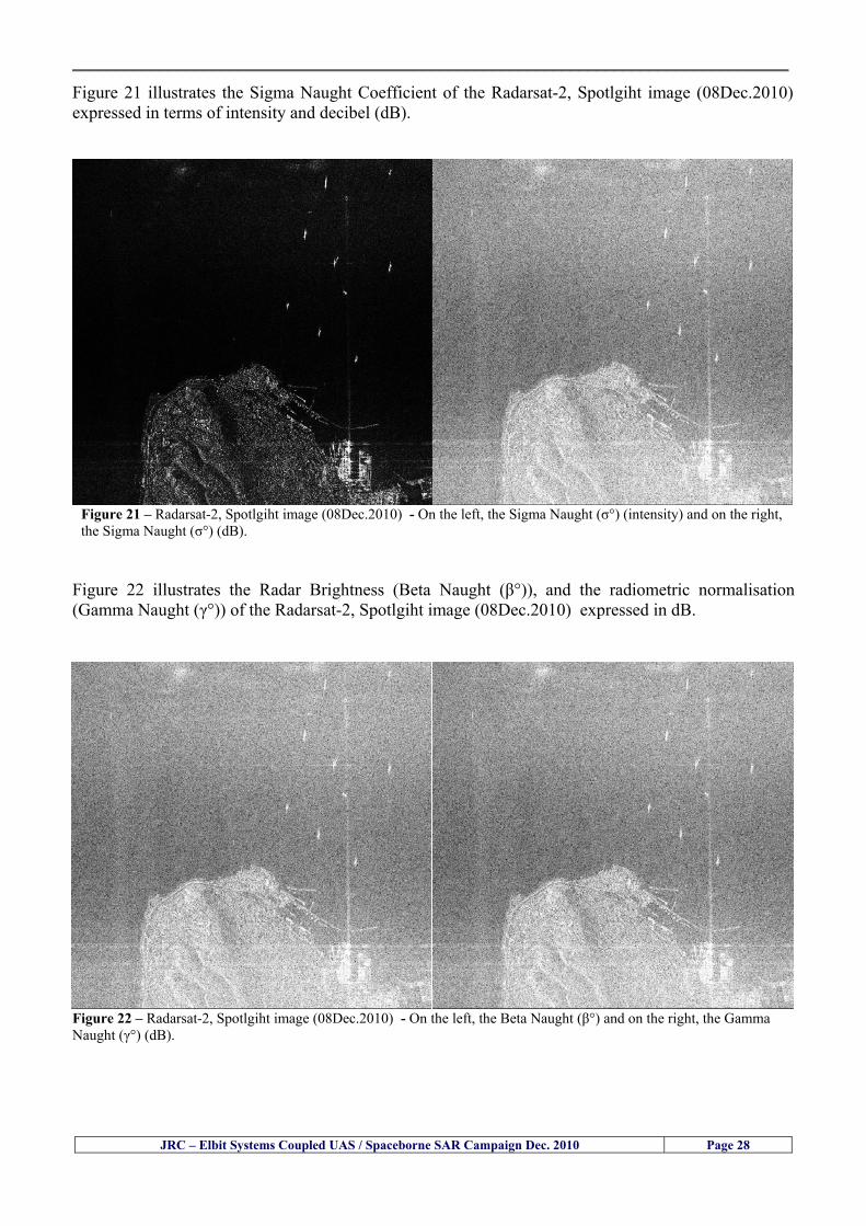
__________________________________________________________________________________
Figure 21 illustrates the Sigma Naught Coefficient of the Radarsat-2 Spotlgiht image (08Dec2010) expressed in terms of intensity and decibel (dB)
Figure 21 ndash Radarsat-2 Spotlgiht image (08Dec2010) - On the left the Sigma Naught (σdeg) (intensity) and on the right the Sigma Naught (σdeg) (dB)
ormalisation amma Naught (γdeg)) of the Radarsat-2 Spotlgiht image (08Dec2010) expressed in dB
-2 Spotlgiht image (08Dec2010) - On the left the Beta Naught (βdeg) and on the right the Gamma Naught (γdeg) (dB)
Figure 22 illustrates the Radar Brightness (Beta Naught (βdeg)) and the radiometric n(G
Figure 22 ndash Radarsat
JRC ndash Elbit Systems Coupled UAS Spaceborne SAR Campaign Dec 2010 Page 28
__________________________________________________________________________________ Figure 23 shows the Sigma Naught (σdeg) in dB after some colour manipulation and the histogram of the Sigma Naught (σdeg) image
Figure 23 ndash Radarsat-2 Spotlgiht image (08Dec2010) - On the top left the Sigma Naught (σdeg) after colour manipulation to enhance the targets and on the top right the corresponding histogram On the bottom we can see the histogram of the image
Table 6 gives the statistics of the Sigma Naught (σdeg) Radarsat-2 Spotlgiht image (08Dec2010) The Sigma Naught (σdeg) range from -72897 dB up to 23465 dB The Mean value is -16855 dB the Median is -16594 dB and the standard deviation is 7077 dB
JRC ndash Elbit Systems Coupled UAS Spaceborne SAR Campaign Dec 2010 Page 29
__________________________________________________________________________________
JRC ndash Elbit Systems Coupled UAS Spaceborne SAR Campaign Dec 2010 Page 30
Table 6 ndash Statistics of the Radarsat-2 Spotlgiht image (08Dec2010) (154740 UTC)
Statistics Values Unit Only ROI-Mask pixels considered Number of pixels total Number of considered pixels Ratio of considered pixels
No 322394283 322394283
1000
Minimum Maximum
-728974609375 234655818939209
intensity_db intensity_db
Mean Median Std-Dev Coefficient of Variation
-16855686580177853 -1659462338617847 707796800831575
07888765273432338
intensity_db intensity_db intensity_db intensity_db
Checking the radar backscattering coefficient of some targets (small boat and some large ships) detected in the Radarsat-2 Spotlight image we get values ranging from -0379 dB up to 23455 dB The analysis of the Sigma Naught values (σdeg) of the targets and the area around the targets shows a significant contrast
56 ndash Summary of the Preliminary Analysis of the Spaceborne SAR Image This experiment involved two spaceborne SAR images namely a TerraSAR-X Stripmap and one Radarsat-2 Spotlight The TerraSAR-X image was not delivered by DLR due to technical problems The Elbitrsquos boat deployed during the experiment was detected in the Radarsat-2 Spotlight image Several other targets including a set of large ships were also detected Table 7 summarises the characteristics of the SAR image acquired and the targets detected
Table 7 ndash List of SAR Satellite Images acquired during the experiment and detected boats ISRAEL (HAIFA)
Date Time Place Satellite Mode Ground Truth Data Detected Boats
08Dec2010 (PM) Haifa - Israel Radarsat-2 Spotlight GPSPhotosMovies 1 small boat deployed + 9 large ships
Table 8 gives the minimum and maximum Sigma Naught (σdeg) of the targets detected in each SAR image
Table 8 ndash Minimum and maximum Sigma Naught (σdeg) of the targets detected in each SAR image
Date Time UTC (LT)Pass Satellite Image Mode Polarisation Sigma Naught (σdeg) Min Max
29Oct2010528UTC(728AM LT) DES Radarsat-2 Spotlight HH --0379 dB 23455 dB The SAR signatures of the boats deployed were very weak Some possible reasons to explain such weak signatures are the sea state the wind speed the incidence angle and the type and materials Another possible reason is the processing at DLR
__________________________________________________________________________________
JRC ndash Elbit Systems Coupled UAS Spaceborne SAR Campaign Dec 2010 Page 31
6 ndash Preliminary Conclusions The analysis of the results of this coupled UASSpaceborne SAR experiment shows a promising potential for the use of UAS for maritime surveillance UAS can be integrated into the airborne building block of maritime surveillance systems to complement the existing assets increase system performance and improve the overall maritime domain awareness The main perceived maritime security and safety threats comprise piracy terrorist and military threats weapons proliferationsmuggling drugs trafficking illegal immigration unlawful use of containers attacks to critical infrastructures and illegal fishing The main maritime security and safety gaps include a lack of technologies with the capability of detecting small targets (eg small boats) a lack of wide area and persistent maritime surveillance a lack of coordination and information sharing limited interoperability a lack of containers security a lack of persistent surveillance of critical infrastructures and early warning systems Unmanned Aircraft Systems (UAS) are an emerging technology with strong potential to mitigate the above mentioned threats by filing in the main maritime security and safety gaps listed earlier For instance the wide range of potential applications of UAS to maritime surveillance includes but is not limited to
bull detection classification and identification of small boats bull persistent maritime surveillance bull use as communications relays bull persistent surveillance of critical infrastructures bull early warning systems bull COMINT and ELINT collection etc
Table 11 illustrates the mapping of maritime securitysafety threats vs gaps and summarises the main potential applications of UAS to maritime surveillance The above mentioned potential applications of UAS to the Maritime Domain will be addressed in turn in more detail next bull Detection classification and identification of small boats ndash The capability of detecting classifying and identifying small targets (eg small boats) is among the key technologies required to improve maritime domain awareness This capability is critical to mitigate piracy illegal immigration drugs trafficking weapons smuggling illegal fishing terrorism and critical infrastructure Unmanned Aircraft Systems (UAS) provide this capability more efficiently and at a lower cost than any other existing technology bull Persistent maritime surveillance ndash With the continuous improvements of UAS technologies such as platforms sensors collision avoidance systems command and control systems telecommunications etc UAS are increasing their autonomy endurance and flexibility These characteristics are very important for persistent maritime surveillance UAS can be launched from land ships aircraft and technologies to launch UAS from submarines are currently under development UAS have distinct advantages over other existing technologies for persistent maritime surveillance in terms of autonomyendurance (the Global Surveyor has an autonomy of 1 week) cost (eg as the autonomy of UAS increases the number of staff required to operate UAS decreases) risk (eg if the UAS crashes the crew is not at risk) flexibility (eg they can be launched from a ship reducing the time to reach potential threats) etc
__________________________________________________________________________________
JRC ndash Elbit Systems Coupled UAS Spaceborne SAR Campaign Dec 2010 Page 32
bull Communications relays ndash UAS are being used as communication relays mainly in military context but have the potential to play a similar role in Civil context in several situations such as to replace satellite communications or as a redundant system over any location on Earth The main advantages of using UAS as communication relays is that airborne communication relays mitigate kinetic and noise jamming threats to satellite communications uplinks by providing an alternative set of links either directly to surface-based terminals or to satellites beyond the range of threats They are less susceptible to noise jamming threats than satellites because an adversary has to detect geolocate and track the airborne asset and operate within line of sight of the receive antenna main beam bull Persistent surveillance of critical infrastructures ndash The security of critical infrastructures such as nuclear power plants refineries ports etc requires persistent surveillance UAS can play an important role in providing persistent surveillance over critical infrastructures and over a wide area around the critical infrastructure Some advantages of UAS over other existing technologies such as ground-based assets (eg video cameras alarm systems manned aircraft etc) comprise the security of the UAS (eg hardly can be damaged or switched off as any ground-based asset) the area covered by a UAS (eg it is larger than the area covered by any ground-based asset) the cost (eg UAS is cheaper than manned aircraft with similar capability) etc bull Early warning systems ndash UAS have the potential to be used as part of an integrated system of systems for early warning A UAS can provide information about a given area at a fraction of the cost of alternative means Formation flying of UAS can cover a wide maritime area It is reasonable to assume that in a foreseeable future with the advent of UAS with increased autonomy the operations cost of UAS will likely decrease making them increasingly more attractive bull COMINT and ELINT collection ndash SIGNal INTelligence (SIGNINT) can be divided into two categories namely COMINT and ELINT COMINT stands for Communication Intelligence and ELINT for Electronic Intelligence Collection of COMINT is passive Exploitation of COMINT requires a human operator which implies COMINT UAS are suitable for COMINT and ELINT collection in different scenarios The relatively reduced amount of data collected and analysed during this experiment and the lessons learned do not allow drawing final conclusions about the feasibility of using Unmanned Aerial Systems (UAS) for maritime surveillance However this experiment allowed hands-on experience with UAS technologies and significantly improved the awareness for its applications to maritime surveillance and related issues involved including its potential the feasibility as well as the limiting and enabling factors These different aspects will now be analysed in turn in the next sections Table 11 illustrates the mapping of the main maritime security threats and gaps as well as the main priorities in terms of the different technologies involved in maritime surveillance For each maritime threat the technologies required to fill in each gap is indicated and its priority is expressed in a range of numbers (1 to 3 1 = Maximum Priority 2 = Medium Priority 3 = Low Priority) and colours (Red = Maximum Priority Orange = Medium Priority Green = Low Priority) The main technologies involved in maritime surveillance are listed on the bottom of figure 4 and are reproduced here for convenience of the reader 1- Reporting Systems 2- Sensors 3- Platforms 4- Communications 5- Data Fusion amp Sharing 6- Intelligence and 7- Databases For example the mitigation of the main threat Piracy requires filling in several maritime security gaps (eg lack of persistent surveillance lack of wide-are maritime surveillance lack of small boat detection lack of Early Warning Systems and lack of Information Sharing with maximum priority (1- Red) and among the required technologies listed are UAS LTAAV GEO-HR etc Concerning the remaining two gaps (Limited Interoperability and Containers Security) they are less relevant to mitigate Piracy hence the priority for Limited Interoperability is 2-Orange and for Containers Security is 3- Green
__________________________________________________________________________________ Table 9 ndash The Main Maritime Security and Safety Threats vs Gaps and the technologies that can be used to mitigate them
Maritime Security Main Threats GapsGapsrarr
darrThreats
Lack o f Risk As sessmentCapab ility
La ck of Persiste nt
Surveilla nce
La ck of Wid e-Area su rve illanc e
La ck of Small Boat De tecti on
Lack o f Earl y Warn ing Sys tems
L ack of In forma tion
Sh arin g
L imi ted In terop era bility
Lac k of Co ntai ners
Se cur ity
bull PiracyUAS LTAVG EO-
HR + UAS LT AVGEO-
HR + SAR GEO-HR
+ UAS USV LTAV
+ UAS LTAV
+ Coord in ationamp Sharing +
Inter opera bilityOptimisation +
1 2 3 5 6 7 1 2 3 5 6 7 1 2 3 5 6 1 2 3 123456 4567 1234567 1234567
bull Terro rismUAS LTAVG EO-
HR + UAS L TAV GEO-HR +
SAR AISGEO-HR +
UAS USV LTAV+
Intelligence+
Inte lligen ce+
Inter opera bilityOptimisation +
Intelligence+
1 2 3 5 6 7 1 2 3 5 6 1 2 3 5 6 1 2 3 123456 4567 1234567 1234567
bull Wea pon s ofM ass Dest ru ctio n Smugg ling
UAS LTAVG EO-HR +
UAS LT AVGEO-HR +
SAR AIS+
UAS USV LTAV+
Intelligence+
Inte lligen ce+
Intelligence+
Intelligence+
1 2 3 5 6 7 1 2 3 5 6 1 2 3 5 6 1 2 3 123456 4567 1234567 1234567
bull Drug sTraffic king
UAS LTAVG EO-HR +
UAS LT AVGEO-HR +
SAR AIS+
UAS USV LTAV+
Intelligence+
Inte lligen ce+
Intelligence+
Intelligence+
1 2 3 5 6 7 1 2 3 5 6 1 2 3 5 6 1 2 3 123456 4567 1234567 1234567
bull Illega lImmigratio n
UAS LTAVG EO-HR +
UAS LT AVGEO-HR +
SAR AIS+
UAS USV LTAV+
Intelligence+
Inte lligen ce+
Intelligence+
Intelligence+
1 2 3 5 6 7 1 2 3 5 6 1 2 3 5 6 1 2 3 123456 4567 1234567 1234567
bull Critic alI nfrastruc tureSecu rit y
UAS LTAVG EO-HR +
UAS LT AVGEO-HR +
SAR AIS+
UAS USV LTAV+ + Inte lligen ce
+ Intelligence
+ Intelligence
+
1 2 3 5 6 7 1 2 3 6 1 2 3 5 6 1 2 3 123456 4567 1234567 1234567
bull Illega lFish ing
UAS LTAVG EO-HR +
AI S+SAR UASLTAV +
SAR AIS GEO-HR+
UAS USV LTAV+
Intelligence+
Inte lligen ce+
Intelligence+
1 2 3 5 6 7 1 2 3 5 7 1 2 3 5 6 1 2 3 123456 4567 1234567
bull Un lawf ul Use of Co nta iners
(Secur ity)
UAS LTAVG EO-HR +
GPS Tr acking+
Intelligence+
Inte lligen ce+
GPS Int rusion Det ection Se al
1 2 3 5 6 7 4 6 7 1 2 3 5 6 1 2 3 123456 4567 1234567 1234567
(-) Priority (+) Not Rel evant
SURVEILLANCETECHNOLOGIES
1- Reporti ng Systems
2 -Sensors 3 -P latforms 4 - Communications 5- Data Fusionamp Sharing
6 -I ntelli gence 7 -Databases
JRC ndash Elbit Systems Coupled UAS Spaceborne SAR Campaign Dec 2010 Page 33
__________________________________________________________________________________
JRC ndash Elbit Systems Coupled UAS Spaceborne SAR Campaign Dec 2010 Page 34
61 ndash Hands-on experience with UAS technologies and its applications to maritime surveillance This coupled UASSpaceborne SAR campaign was a unique opportunity to acquire further handsndashon experience with UAS technologies and learn about the main issues related to its applications to maritime surveillance From the planning phase up to the execution of the UAS flight and landing there are several factors that need to be carefully analysed and taken into account A summary of the main issues identified in this experiment is given next 1- Selection of the Experiment Area Authorisation to Fly ndash For the time being UAS can only be flown in restricted areas usually under control of national authorities often the military This is due to the risks that a UAS can pose to human life and property In the present case an area under the authority of the Israeli Civil Aviation Authority was selected The authorisation to fly was not easy to obtain because the selected area is under the authority of the Civil Aviation Authority Figure 24 indicates the area of the experiment in Haifa Israel 2- UAS Communications Issues ndash The Hermes 450 was flown in Line-of-Sight (LOS) since it was close to the coast For BLOS (Beyond Line-of-Sight) operation satellite communications are required 3- Synthetic Aperture Radar (SAR) ndash The specific model Hermes 450W used in the experiment had no SAR sensor installed However a SAR sensor can be installed A SAR sensor is important for maritime surveillance since it allows 247 operations regardless of the weather conditions 4- Automatic Identification System (AIS) Receiver ndash The Hermes 450 used in this experiment was not equipped with an AIS receiver For maritime surveillance operations an AIS receiver is a very important tool since it allows the automatic identification of most ships allowing the UAS to concentrate on non-identified ships
__________________________________________________________________________________
Figure 24 ndash The area of the experiment is indicated by the GPS Trajectory of the UAV
62 ndash Potential of UAS for Maritime Surveillance UAS technologies are relatively recent and involve a wide range of fields spanning from aeronautics and sensors technologies to satellite communications and other engineering disciplines Innovations in each of the fields involved are emerging by the day UAS still have a long way to go before they become mature and their use fully operational For the time being UAS are mainly used for military applications However a large number of non-military UAS applications have been identified by stakeholders and there are several studies and demonstration flights foreseen for the near future Maritime surveillance is one of the most challenging and promising fields of application of UAS The challenges are due to the very demanding conditions under which the UAS must operate over sea and the requirements for safe operation
JRC ndash Elbit Systems Coupled UAS Spaceborne SAR Campaign Dec 2010 Page 35
__________________________________________________________________________________
JRC ndash Elbit Systems Coupled UAS Spaceborne SAR Campaign Dec 2010 Page 36
The present UAS experiment has unveiled some of the potential of UAS for maritime surveillance The UAS tests performed during this experiment include
1 ndash Detection of a Small rubber Boat and a Fishing Ship 2 ndash Tracking of a Small Boat and a Fishing Ship 3 ndash Classification of a Small Boat and a Fishing Ship 4 ndash Identification of a Small Boat and a Fishing Ship 5 ndash Detection and Tracking of People on the Beach
Despite the operational requirement that prevented the UAS from flying bellow 3km the experiment has confirmed the capability of UAS for small boat detection tracking and classification as well as the capability for people detection and tracking Concerning the identification of the targets the characteristics of the images acquired during this mission suggest that flying at lower altitudes the UAS images would allow the identification of the targets The UAS images can be seen from Figure 15 to 20
621 ndash Advantages of UAS for maritime Surveillance Some of the advantages of using UAS for maritime surveillance have been described in the literature and are summarized bellow
1- One potential benefit of UAS is that they could fill in a gap in current maritime surveillance by improving coverage
2- The range of UAS is a significant asset when compared to border agents on patrol or stationary surveillance equipment
3- Eletro-Optical InfraRed (EOIR) sensors (cameras) can identify small size objects from very high altitudes (high resolution)
4- UAS can provide precise and near-real-time imagery to a ground control operator who would then disseminate that information so that informed decisions regarding the deployment of border patrol agents can be made quickly
5- Long endurance UAS used along the border can fly for more than 30 hours up to several days without having to refuel compared with manned helicopterrsquos average flight time of just over 2 hours
6- The ability of UAS to loiter for prolonged periods of time has important operational advantages over manned aircraft
7- The longer flight times of UAS means that sustained coverage over a previously exposed area may improve maritime security
8- The range of UAVs is a significant asset when compared to border agents on patrol or stationary surveillance equipment Nevertheless the extended range and endurance of UAVs may lessen the burdens on human resources at the borders
9- UAS accidents do not risk the lives of pilots as do the helicopters and aircraft currently used by Coast Guards for border patrolling
__________________________________________________________________________________
JRC ndash Elbit Systems Coupled UAS Spaceborne SAR Campaign Dec 2010 Page 37
622 ndash Possible Drawbacks of using UAS for maritime Surveillance UAS also have disadvantages some of them are briefly described next
1- There have been concerns regarding the high accident rate of UAS which can be multiple times higher than that of manned aircraft Because UAS technology is still evolving there is less redundancy built into the operating system of UAS than of manned aircraft and until redundant systems are perfected mishap rates are expected to remain high
2- If control systems fail in a manned aircraft a well-trained pilot is better positioned to find the source of the problem because of hisher physical proximity If a UAS encountered a similar system failure or if a UAS landing was attempted during difficult weather conditions the ground control pilot would be at a disadvantage because he or she is removed from the event Unlike a manned pilot the remote pilot would not be able to assess important sensory information such as wind speed
3- Inclement weather conditions can also impinge on a UAS surveillance capability especially UAS equipped with only an EO camera and Forward Looking Infrared Radar (FLIR) because cloudy conditions and high humidity climates can distort the imagery produced by EO and FLIR equipment The effects of extreme climatic or atmospheric conditions on sensors reportedly can be mitigated with the outfit of one synthetic aperture radar (SAR) system and a moving target indicator (MTI) radar However adding SAR and MTI to a UAS platform would increase the costs associated with using UAS
4- Depending on the type of UAS the costs of operating a UAS can be higher than the costs of operating a manned aircraft This is because some types of UAS require a significant amount of logistical support and specialized operator and maintenance training Operating one UAS may require a crew of up to 20 support personnel The high comparative costs of operating some sophisticated types of UAS may be offset somewhat by their comparatively lower unit costs
63 ndash Main Limiting Factors Preventing the Use of UAS Several pre-requisites must be satisfied to render the UAS a viable cost-effective and regulated alternative to existing resources Major civil and commercial market barriers include
Single European Sky Sense and Avoid technologies Command and Control Technologies Reliability Communications (Bandwidth LOS BLOS)
Lack of airspace regulation that covers all types of UAV systems (encompassing lsquosense and avoidrsquo airspace integration and airworthiness issues)
Affordability - price and customization issues (eg commercial off-the-shelf open modular architecture) Lack of efforts to establish joint customer requirements (although this is gradually changing) Liability for civil operation Capacity for payload flexibility Lack of sufficient secure non-military frequencies for civil operation Perceived reliability (eg vehicle attrition rate vs manned aircraft) Operator training issues Recognitioncustomer perception of the UAV market Technology developments for multi-mission capability
__________________________________________________________________________________
64 ndash UAS Key Enabling Technologies Figure 25 illustrates the components of a typical UAV System showing some of the capabilities needed and the enabling technologies required for performing a given mission Any UAV mission involves many capabilities and technologies Due to the depicted system complexity the main key players such as the US Department of Defense (DoD) and other agencies have started to use the term Unmanned Aerial System (UAS) in place of UAV
Figure 25 ndash Unmanned Aerial Vehicle System Enabled by Autonomous Mission Management Reliable Flight Systems Navigation Accurate Systems Terrain Avoidance Power and Propulsion Some UAS key enabling technologies are listed below
Autonomous Mission Management Collision Avoidance Intelligent System Health Monitoring
Reliable Flight Systems Sophisticated Contingency Management Intelligent Data Handling and Processing Over-the-Horizon Communication Network-Centric Communication Open Architecture Power and Propulsion Navigation Accurate System Technology Enhanced Structures
JRC ndash Elbit Systems Coupled UAS Spaceborne SAR Campaign Dec 2010 Page 38
__________________________________________________________________________________
JRC ndash Elbit Systems Coupled UAS Spaceborne SAR Campaign Dec 2010 Page 39
Table 12 gives a more detailed description of other critical technologies for emerging autonomous UAV systems both civil and military Most of the technologies mentioned in Table 12 apply both to civil and military UAV systems Table 10 ndash Key Enabling Technologies (from SG75 study on autonomous systems)
Critical Technologies Decision Making Software
bull Fuzzy-based decision making bull Knowledge-based system bull Case-based reasoning bull Self-learning techniques bull Decision tree evaluation bull ReasoningInferring bull Probabilisticstochastic reasoning
Prediction Algorithms bull Predictive pathintent algorithms bull Short reaction algorithm bull Effectiveness evaluation
Status Assessment Software bull Internal status analysis bull Self-orientation
Situation Analysis Software bull Situation analysis bull Environmental analysis bull External status analysis
Modelling Software bull Air vehicle modelling algorithms bull Sensor modelling algorithms bull Scenario generation bull Threat system modeling bull Attack simulation bull Mission success optimisation model bull Simulation
Sensor Processing Software bull Sensor fusion bull Area of interest identification bull Automatic target recognition
Adaptive and Self-learning Systems bull Failure self-compensation
Attack Planning Software bull Attack plans and tactical alternatives bull Plan change impact identification
Weapon Engagement Procedure Software bull Weapon engagement algorithms
Mission Plan Update Software bull Route planning system bull Payload plan management system bull Mission Success Optimisation model
Path Optimisation Software bull Optimal trajectory planning bull Path Optimisation System
Targeting Software bull Target tracking bull Target prioritisation
Platform Technologies bull Obstacle detection and avoidance (airborne) bull Obstacle detection and avoidance (ground) bull Improved autopilot bull Speech recognition
Figure 26 summarises system element designs needed to transition from current to next-generation autonomous UAV systems for civilian and military UAS
__________________________________________________________________________________
Figure 26 ndash System Element Designs Needed to Transition from Current to Next-Generation Autonomous UAV Systems These new paradigms are a combination of system attributes and technological capabilities For instance the data fusion secure anti-jam and coordinated multi-vehicle control require technological development as well as specific system development to bring full maturity to unmanned systems Finally very small Micro UAVs (MAVs) and relatively large sophisticated UCAV systems are examples of the range of UAVs that are applying the new platforms payloads onboard processing communications etc to create next generation automated UAVs It is with these new platforms payloads etc that both UCAVs and MAV will be able to address similar operational challenges including
Mixed operation with other assets bull Deconfliction collision avoidance C4I integration
Operation over populated areas bull Safety issues Need to reduce reliance on communications bull UCAV ndash countermeasures bull MAV ndash limited size and power bull Limited line of sight environment Need a fully integrated system bull MAV propulsionpower generation still critical bull Operator machine interface critical bull All weather operations bull Survivability
JRC ndash Elbit Systems Coupled UAS Spaceborne SAR Campaign Dec 2010 Page 40
__________________________________________________________________________________
JRC ndash Elbit Systems Coupled UAS Spaceborne SAR Campaign Dec 2010 Page 41
65 ndash Mission Readiness
651 ndash Mission Readiness Summary This section summarises civil UAV mission readiness The purpose of Mission Readiness is to assess the readiness status of the different technologies involved in UAS In the present case this civil UAV mission readiness based on technology maturation forecasts that meet or exceed the desired or required capabilities identified by the user community Figure 27 summarises the mission readiness time forecasts for the different technologies The technologies annotated with an asterisk () are shown within the figure with maturation forecasts based on development targets expressed in the US Department of Defencesrsquo UAV Roadmap document The purpose of the chart is to be able to identify when the capability to fly a particular mission can be expected as a function of time The left-most end is the least probable and the right end the most probable timeframe
Figure 27 ndash Technology Maturation Summaries in Terms of Mission-Derived Capabilities
__________________________________________________________________________________
JRC ndash Elbit Systems Coupled UAS Spaceborne SAR Campaign Dec 2010 Page 42
66 ndash Small Boat Detection in SAR Satellite Imagery The use of spaceborne SAR imagery for small boat detection requires additional small boat detection experiments under different conditions using different methods It is not possible to draw final conclusions based on a limited number of small boat detection experiments which are not representative of the multiple possible scenarios
67 ndash Limitations of current State-of-the-Art SAR Satellite technology The main limitations of current State-of-the-Art spaceborne SAR imagery for maritime surveillance in particular aimed at small boat detection are 1 - SAR satellites repeat cycles do not allow the coverage of the same area at the required time intervals Constellations of SAR satellites could be a solution 2 - The conflict between resolution and image swath High resolution is required to detect small boats However the high resolution images have small swaths Maritime surveillance with high resolution images would require a large number of images to cover wide maritime areas which is very expensive and for the time being technically not feasible Intelligence data can play an important role by indicating an approximate position of suspicious non cooperative targets therefore reducing the surveillance area which can then be imaged using high resolution images 3- Spaceborne high resolution SAR imagery acquisition times are long enough to allow significant motion of the target during the acquisition time degrading the quality of the image Further research efforts are needed to develop new sensors and platforms As far as sensors are concerned shorter integration times are needed to prevent the blurring effect caused by the motion of the targets Regarding the platforms more platforms are needed to allow lower repeat cycles and improved coverage
__________________________________________________________________________________
JRC ndash Elbit Systems Coupled UAS Spaceborne SAR Campaign Dec 2010 Page 43
7 ndash Plans for Future Work The controlled experiments carried out by the EC-JRC together with Elbit Systems in Haifa-Israel comprised the deployment of a UAS (Hermes-450) and one small 12-meter boat A Radarsat-2 Spotlight image was acquired and several images collected by the Hermes-450 The experiment unveiled the potential of UAS for maritime surveillance in particular for detection tracking classification and possible identification of small targets The UAS was able to detect track and classify small targets such as small boats For low UAS altitude flights identification may be possible in some cases The small 12-meter boat was detected in the spaceborne SAR image The small boat detection trials carried out by the JRC were very successful since most small boats deployed during the experiments were detected in different sea states wind speeds and geographical locations The several small boat detection campaigns conducted by the EC-JRC seem to suggest that the probability of detection of small boats in spaceborne SAR images strongly depends on factors such as the sea state the wind speed the type of boat (shape and materials) the weather conditions among other factors The results of the experiments conducted thus far are not enough to draw final conclusions about the feasibility of using spaceborne SAR imagery for small boat detection However the experiments have an overall positive outcome because they indicate that under suitable sea state and wind speed conditions it is possible to detect small boats using spaceborne SAR The estimation of the probability of detection of small boats in spaceborne SAR images requires a large number of experiments under different circumstances (eg sea state wind speed characteristics of the targets image type and mode etc) Future plans include additional UAS experiments to asses its potential for maritime surveillance
Acknowledgements ndash The authors would like to express their gratitude to Elbit Systems for their cooperation logistical support and assets deployed without which the present coupled UASSAR Satellite Small Boat Detection Campaign would have not been possible
__________________________________________________________________________________
JRC ndash Elbit Systems Coupled UAS Spaceborne SAR Campaign Dec 2010 Page 44
REFERENCES [1] Elbit Systems ldquoUAV Elbit Systems Proposal for Unmanned Aerial Vehicle (UAV) flight to
collect Ground Truth data during a Maritime Surveillance Campaign and demonstrate UAV capabilities for Maritime Surveillancerdquo 2010
[2] ndash Cheryl Yuhas Suborbital Science Program Manager NASA Science Mission Directorate ldquoEarth Observations and the Role of UAVs A Capabilities Assessment Version 11rdquo Civil UAV Assessment Team httpwwwnasagovcentersdrydenresearchcivuavindexhtml August 2006
[3] ndash Document NIAG (SG75) NATO Industrial Advisory Group Study Group 75 Pre-Feasibility Study on UAV Autonomous Operations 2004
[4] ndash United States Department of Defence (DoD) Directive 50001 ldquoThe Defense Acquisition Systemrdquo and DoD Instruction 50002 ldquoOperation of the Defense Acquisition Systemrdquo
[5] ndash Mr James Ramage Mr Massimo Avalle Dr Erik Berglund Dr Luigi Crovella Mr Robert Frampton Dr Uwe Krogmann Mr Christian Ravat Mr Mike Robinson Dr Axel Schulte Dr Scott Wood ldquoRTO-TR-SCI-118 - Automation Technologies and Application Considerations for Highly Integrated Mission Systemsrdquo RTO-TR-SCI-118 AC323(SCI-118)TP204 January 2009
[6] Victor MG Silva Gilles Jurquet Gabriel Marchalot Maria TG Calzado Txema Soroa Juan Sancho Adam Koubek Harm Greidanus and Claudio Savarino ldquoWide Maritime Area Airborne Surveillance (WIMA2S) WP5 Final Reportrdquo WIMAAS WP5 FP7 Project 2008-2011 - ISBN-978-92-79-22801-8 (print) 978-92-79-22802-5 (PDF) ISSN-1018-5593 (print) 1831-9424 (online) EC-JRC Scientific Report JRC 70093 2012
[7] Victor MG Silva and Harm Greidanus ldquoSpaceborne SAR Small Boat Detection Campaign in Portugal and Spainrdquo EUR 25281 EN ISBN 978-92-79-22553-6 ISSN 1831-9424 (online) EC-JRC Scientific Report JRC68160 2012
[8] Goncalves Da Silva V Van Wimersma Greidanus H Hejmanowska B Loudjani P ldquoUAS Applications With Societal Benefits ndash JRCrsquos UAS-Related Activitiesrdquo 2011-2012 UAS Yearbook - UAS Unmanned Aircraft Systems - The Global Perspective 9 (9) 2011 p 127-129 JRC66600
[9] Goncalves Da Silva V Van Wimersma Greidanus H ldquoSmall boat detection using TerraSAR-X and Radarsat2 satellite imageryrdquo 4th TerraSAR-X Science Team Meeting 14 February 2011 DLR Oberpfaffenhofen (Germany) German Aerospace Center (DLR) (Organiser) 2011 JRC63663
[10] V Silva Harm Greidanus ldquoJRC - SAR Satellite Small Boat Detection Campaign - Portoroz ndash Sloveniardquo - ISBN-13 978-92-79-21476-9 ISSN (online) 1831-9424 EC-JRC Scientific Report JRC66835 2011
[11] V Silva Harm Greidanus ldquoJRC - SAR satellite small boat detection campaign - Algarve Portugalrdquo - ISBN-13 978-92-79-21265-9 ISSN (online) 1831-9424 ISSN (print) 1018-5593 EC-JRC Scientific Report JRC66631 2011
[12] ndash Goncalves Da Silva V Van Wimersma Greidanus H ldquoJRC-Frontex Spaceborne SAR Small Boat Detection Campaign ndash Italy amp Spainrdquo - ISBN-13 978-92-79-22213-9 ISSN (online) 1831-9424 EC-JRC Scientific Report JRC67517 2011
[13] - PW Vachon SJ Thomas J Cranton HR Edel and MD Henschel Validation of ship detection by the RADARSAT synthetic aperture radar and the Ocean Monitoring Workstation Canadian Journal of Remote Sensing 26(3)200ndash212 2000
[14] - Crisp D (2004) The state-of-the-art in ship detection in Synthetic Aperture Radar imagery DSTO Information Sciences Laboratory Australia
[15] - Joint Research Centre (JRC) of the European Community mdash IMPAST and DECLIMS web site httpintelligencejrcceceuintmarinefishindexhtm
[16] - McCandless SW Jackson CR (2004) Principles of Synthetic Aperture Radar Synthetic Aperture Radar Marine Users Manual NOAA Washington pp 1-23
[17] - Greidanus H (2008) Satellite Imaging for Maritime Surveillance of the European Seas Remote Sensing of the European Seas 343-358
European Commission
EUR 25346 EN --- Joint Research Centre --- Institute for the Protection and Security of the Citizen
Title JRC --- Elbit Systems Coupled UAS and Spaceborne SAR Campaign in Israel
Authors Victor MG Silva Harm Greidanus
Luxembourg Publications Office of the European Union
2012 --- v+44 pp --- 210 x 297 cm
EUR --- Scientific and Technical Research series --- ISSN 181-9424 (online) ISSN 1018-5593 (print)
ISBN 978-92-79-25020-0
doi10278828527
Abstract The European maritime area is one of Europersquos most important assets with regard to resources security and ultimately
prosperity of the Member States A significant part of Europersquos economy relies directly or indirectly on it It is not just the
shipping or fisheries industries and their related activities It is also shipbuilding and ports marine equipment and offshore
energy maritime and coastal tourism aquaculture submarine telecommunications blue biotech and the protection of the
marine environment The European maritime area faces several risks and threats posed by unlawful activities such as drugs
trafficking smuggling illegal immigration organised crime and terrorism Piracy in international waters also constitutes a threat
to Europe since it can disrupt the maritime transport chain These risks and threats can endanger human lives marine resources
and the environment as well as significantly disrupt the transport chain and global and local security It is anticipated that these
risks and threats will endure in the mid and long run In order to keep Europe as a world leader in the global maritime economy
an effective integratedinteroperable sustainable maritime surveillance system and situational awareness are needed
A significant number of unlawful maritime activities such as illegal immigration drugs trafficking smuggling piracy and
terrorism involve mainly small boats because small boats are faster and more difficult to detect using conventional means
Hence it is very important to find out the feasibility of using Unmanned Aerial Systems (UAS) for small boat detection tracking
classification and identification as well as to study the potential of UAS for maritime surveillance Since 2010 the EC-JRC has
carried out a number of UAS maritime surveillance campaigns to study the potential of UAS for maritime surveillance in
particular for small boat detection This report presents the results and conclusions of the JRC --- Elbit Systems Coupled UAS and
Spaceborne SAR campaign carried out in Dec 2010 in Haifa Israel
As the Commissionrsquos in-house science service the Joint Research Centrersquos mission is to provide EU policies with independent evidence-based scientific and technical support throughout the whole policy cycle Working in close cooperation with policy Directorates-General the JRC addresses key societal challenges while stimulating innovation through developing new standards methods and tools and sharing and transferring its know-how to the Member States and international community Key policy areas include environment and climate change energy and transport agriculture and food security health and consumer protection information society and digital agenda safety and security including nuclear all supported through a cross-cutting and multi-disciplinary approach
LB-NA-25346-EN
-N
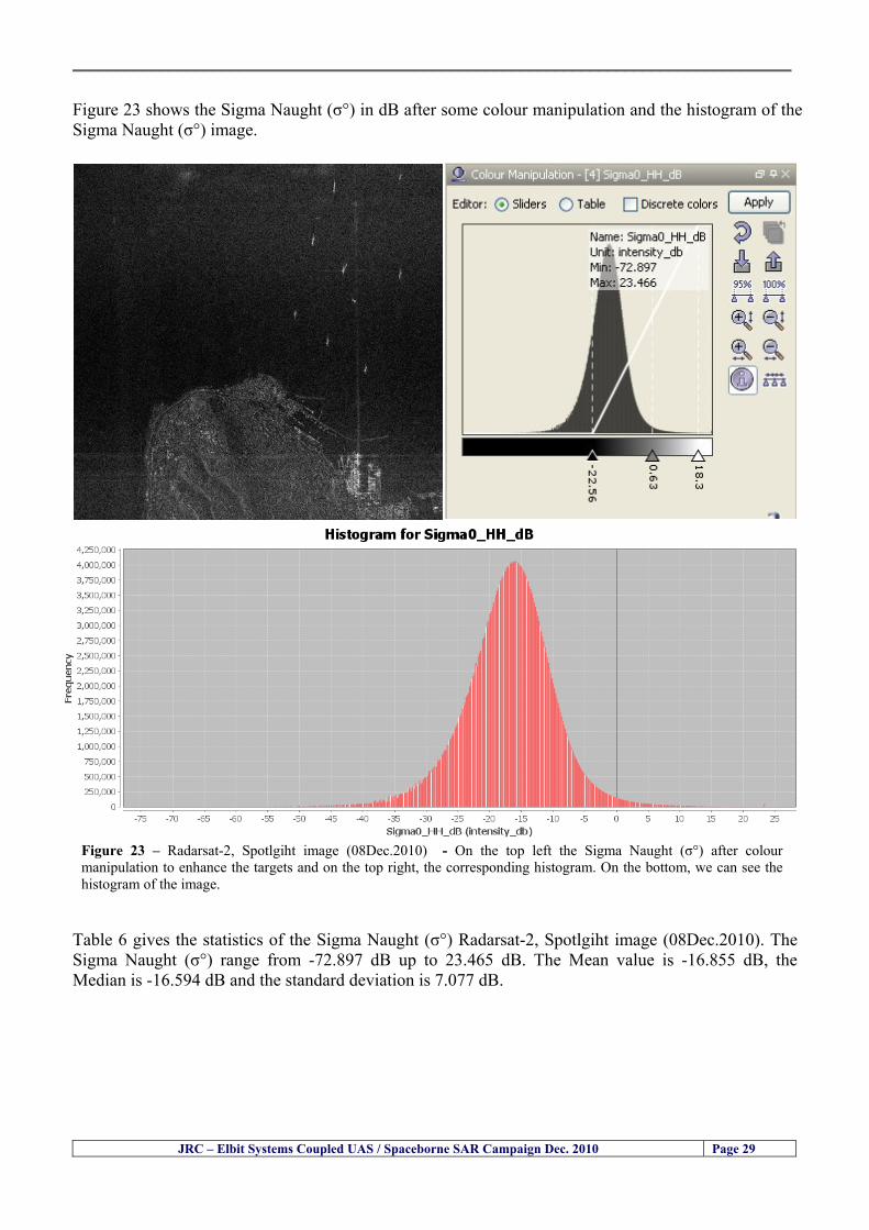
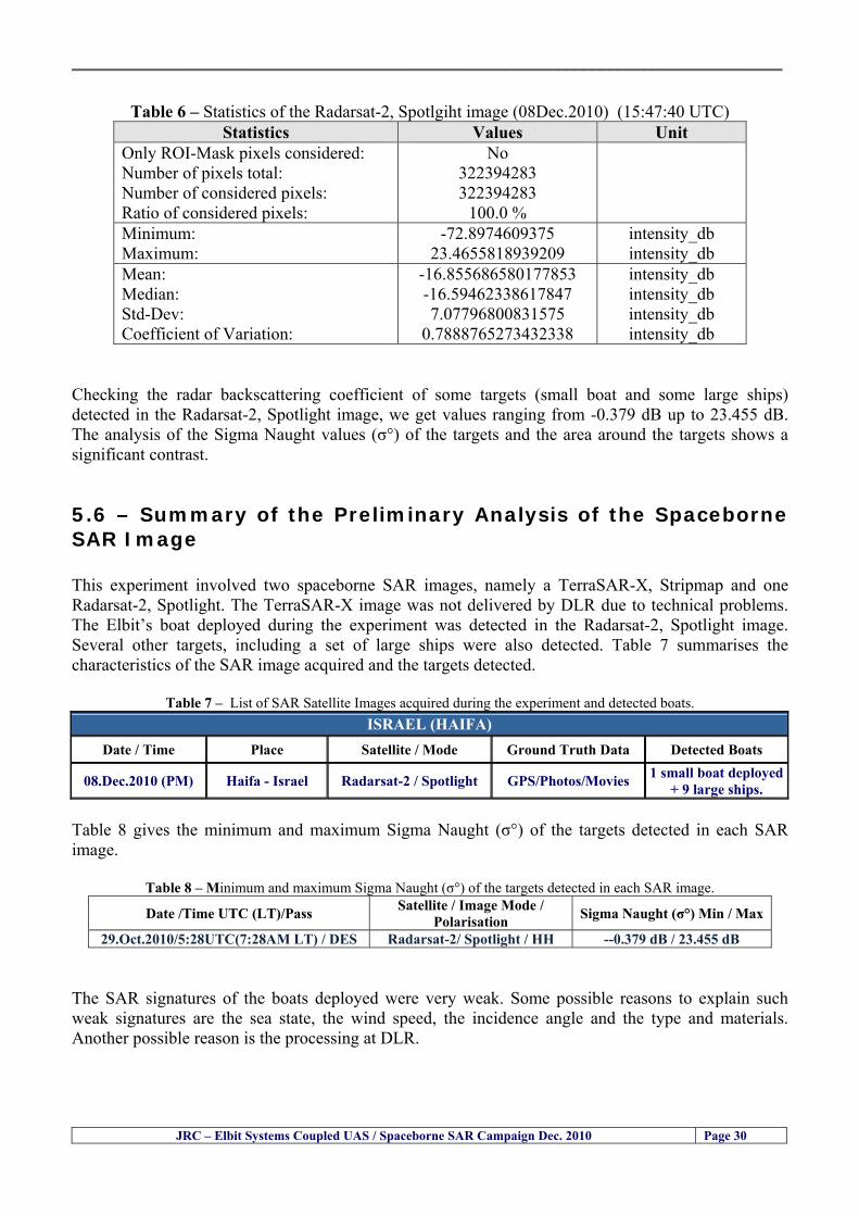
__________________________________________________________________________________
JRC ndash Elbit Systems Coupled UAS Spaceborne SAR Campaign Dec 2010 Page 30
Table 6 ndash Statistics of the Radarsat-2 Spotlgiht image (08Dec2010) (154740 UTC)
Statistics Values Unit Only ROI-Mask pixels considered Number of pixels total Number of considered pixels Ratio of considered pixels
No 322394283 322394283
1000
Minimum Maximum
-728974609375 234655818939209
intensity_db intensity_db
Mean Median Std-Dev Coefficient of Variation
-16855686580177853 -1659462338617847 707796800831575
07888765273432338
intensity_db intensity_db intensity_db intensity_db
Checking the radar backscattering coefficient of some targets (small boat and some large ships) detected in the Radarsat-2 Spotlight image we get values ranging from -0379 dB up to 23455 dB The analysis of the Sigma Naught values (σdeg) of the targets and the area around the targets shows a significant contrast
56 ndash Summary of the Preliminary Analysis of the Spaceborne SAR Image This experiment involved two spaceborne SAR images namely a TerraSAR-X Stripmap and one Radarsat-2 Spotlight The TerraSAR-X image was not delivered by DLR due to technical problems The Elbitrsquos boat deployed during the experiment was detected in the Radarsat-2 Spotlight image Several other targets including a set of large ships were also detected Table 7 summarises the characteristics of the SAR image acquired and the targets detected
Table 7 ndash List of SAR Satellite Images acquired during the experiment and detected boats ISRAEL (HAIFA)
Date Time Place Satellite Mode Ground Truth Data Detected Boats
08Dec2010 (PM) Haifa - Israel Radarsat-2 Spotlight GPSPhotosMovies 1 small boat deployed + 9 large ships
Table 8 gives the minimum and maximum Sigma Naught (σdeg) of the targets detected in each SAR image
Table 8 ndash Minimum and maximum Sigma Naught (σdeg) of the targets detected in each SAR image
Date Time UTC (LT)Pass Satellite Image Mode Polarisation Sigma Naught (σdeg) Min Max
29Oct2010528UTC(728AM LT) DES Radarsat-2 Spotlight HH --0379 dB 23455 dB The SAR signatures of the boats deployed were very weak Some possible reasons to explain such weak signatures are the sea state the wind speed the incidence angle and the type and materials Another possible reason is the processing at DLR
__________________________________________________________________________________
JRC ndash Elbit Systems Coupled UAS Spaceborne SAR Campaign Dec 2010 Page 31
6 ndash Preliminary Conclusions The analysis of the results of this coupled UASSpaceborne SAR experiment shows a promising potential for the use of UAS for maritime surveillance UAS can be integrated into the airborne building block of maritime surveillance systems to complement the existing assets increase system performance and improve the overall maritime domain awareness The main perceived maritime security and safety threats comprise piracy terrorist and military threats weapons proliferationsmuggling drugs trafficking illegal immigration unlawful use of containers attacks to critical infrastructures and illegal fishing The main maritime security and safety gaps include a lack of technologies with the capability of detecting small targets (eg small boats) a lack of wide area and persistent maritime surveillance a lack of coordination and information sharing limited interoperability a lack of containers security a lack of persistent surveillance of critical infrastructures and early warning systems Unmanned Aircraft Systems (UAS) are an emerging technology with strong potential to mitigate the above mentioned threats by filing in the main maritime security and safety gaps listed earlier For instance the wide range of potential applications of UAS to maritime surveillance includes but is not limited to
bull detection classification and identification of small boats bull persistent maritime surveillance bull use as communications relays bull persistent surveillance of critical infrastructures bull early warning systems bull COMINT and ELINT collection etc
Table 11 illustrates the mapping of maritime securitysafety threats vs gaps and summarises the main potential applications of UAS to maritime surveillance The above mentioned potential applications of UAS to the Maritime Domain will be addressed in turn in more detail next bull Detection classification and identification of small boats ndash The capability of detecting classifying and identifying small targets (eg small boats) is among the key technologies required to improve maritime domain awareness This capability is critical to mitigate piracy illegal immigration drugs trafficking weapons smuggling illegal fishing terrorism and critical infrastructure Unmanned Aircraft Systems (UAS) provide this capability more efficiently and at a lower cost than any other existing technology bull Persistent maritime surveillance ndash With the continuous improvements of UAS technologies such as platforms sensors collision avoidance systems command and control systems telecommunications etc UAS are increasing their autonomy endurance and flexibility These characteristics are very important for persistent maritime surveillance UAS can be launched from land ships aircraft and technologies to launch UAS from submarines are currently under development UAS have distinct advantages over other existing technologies for persistent maritime surveillance in terms of autonomyendurance (the Global Surveyor has an autonomy of 1 week) cost (eg as the autonomy of UAS increases the number of staff required to operate UAS decreases) risk (eg if the UAS crashes the crew is not at risk) flexibility (eg they can be launched from a ship reducing the time to reach potential threats) etc
__________________________________________________________________________________
JRC ndash Elbit Systems Coupled UAS Spaceborne SAR Campaign Dec 2010 Page 32
bull Communications relays ndash UAS are being used as communication relays mainly in military context but have the potential to play a similar role in Civil context in several situations such as to replace satellite communications or as a redundant system over any location on Earth The main advantages of using UAS as communication relays is that airborne communication relays mitigate kinetic and noise jamming threats to satellite communications uplinks by providing an alternative set of links either directly to surface-based terminals or to satellites beyond the range of threats They are less susceptible to noise jamming threats than satellites because an adversary has to detect geolocate and track the airborne asset and operate within line of sight of the receive antenna main beam bull Persistent surveillance of critical infrastructures ndash The security of critical infrastructures such as nuclear power plants refineries ports etc requires persistent surveillance UAS can play an important role in providing persistent surveillance over critical infrastructures and over a wide area around the critical infrastructure Some advantages of UAS over other existing technologies such as ground-based assets (eg video cameras alarm systems manned aircraft etc) comprise the security of the UAS (eg hardly can be damaged or switched off as any ground-based asset) the area covered by a UAS (eg it is larger than the area covered by any ground-based asset) the cost (eg UAS is cheaper than manned aircraft with similar capability) etc bull Early warning systems ndash UAS have the potential to be used as part of an integrated system of systems for early warning A UAS can provide information about a given area at a fraction of the cost of alternative means Formation flying of UAS can cover a wide maritime area It is reasonable to assume that in a foreseeable future with the advent of UAS with increased autonomy the operations cost of UAS will likely decrease making them increasingly more attractive bull COMINT and ELINT collection ndash SIGNal INTelligence (SIGNINT) can be divided into two categories namely COMINT and ELINT COMINT stands for Communication Intelligence and ELINT for Electronic Intelligence Collection of COMINT is passive Exploitation of COMINT requires a human operator which implies COMINT UAS are suitable for COMINT and ELINT collection in different scenarios The relatively reduced amount of data collected and analysed during this experiment and the lessons learned do not allow drawing final conclusions about the feasibility of using Unmanned Aerial Systems (UAS) for maritime surveillance However this experiment allowed hands-on experience with UAS technologies and significantly improved the awareness for its applications to maritime surveillance and related issues involved including its potential the feasibility as well as the limiting and enabling factors These different aspects will now be analysed in turn in the next sections Table 11 illustrates the mapping of the main maritime security threats and gaps as well as the main priorities in terms of the different technologies involved in maritime surveillance For each maritime threat the technologies required to fill in each gap is indicated and its priority is expressed in a range of numbers (1 to 3 1 = Maximum Priority 2 = Medium Priority 3 = Low Priority) and colours (Red = Maximum Priority Orange = Medium Priority Green = Low Priority) The main technologies involved in maritime surveillance are listed on the bottom of figure 4 and are reproduced here for convenience of the reader 1- Reporting Systems 2- Sensors 3- Platforms 4- Communications 5- Data Fusion amp Sharing 6- Intelligence and 7- Databases For example the mitigation of the main threat Piracy requires filling in several maritime security gaps (eg lack of persistent surveillance lack of wide-are maritime surveillance lack of small boat detection lack of Early Warning Systems and lack of Information Sharing with maximum priority (1- Red) and among the required technologies listed are UAS LTAAV GEO-HR etc Concerning the remaining two gaps (Limited Interoperability and Containers Security) they are less relevant to mitigate Piracy hence the priority for Limited Interoperability is 2-Orange and for Containers Security is 3- Green
__________________________________________________________________________________ Table 9 ndash The Main Maritime Security and Safety Threats vs Gaps and the technologies that can be used to mitigate them
Maritime Security Main Threats GapsGapsrarr
darrThreats
Lack o f Risk As sessmentCapab ility
La ck of Persiste nt
Surveilla nce
La ck of Wid e-Area su rve illanc e
La ck of Small Boat De tecti on
Lack o f Earl y Warn ing Sys tems
L ack of In forma tion
Sh arin g
L imi ted In terop era bility
Lac k of Co ntai ners
Se cur ity
bull PiracyUAS LTAVG EO-
HR + UAS LT AVGEO-
HR + SAR GEO-HR
+ UAS USV LTAV
+ UAS LTAV
+ Coord in ationamp Sharing +
Inter opera bilityOptimisation +
1 2 3 5 6 7 1 2 3 5 6 7 1 2 3 5 6 1 2 3 123456 4567 1234567 1234567
bull Terro rismUAS LTAVG EO-
HR + UAS L TAV GEO-HR +
SAR AISGEO-HR +
UAS USV LTAV+
Intelligence+
Inte lligen ce+
Inter opera bilityOptimisation +
Intelligence+
1 2 3 5 6 7 1 2 3 5 6 1 2 3 5 6 1 2 3 123456 4567 1234567 1234567
bull Wea pon s ofM ass Dest ru ctio n Smugg ling
UAS LTAVG EO-HR +
UAS LT AVGEO-HR +
SAR AIS+
UAS USV LTAV+
Intelligence+
Inte lligen ce+
Intelligence+
Intelligence+
1 2 3 5 6 7 1 2 3 5 6 1 2 3 5 6 1 2 3 123456 4567 1234567 1234567
bull Drug sTraffic king
UAS LTAVG EO-HR +
UAS LT AVGEO-HR +
SAR AIS+
UAS USV LTAV+
Intelligence+
Inte lligen ce+
Intelligence+
Intelligence+
1 2 3 5 6 7 1 2 3 5 6 1 2 3 5 6 1 2 3 123456 4567 1234567 1234567
bull Illega lImmigratio n
UAS LTAVG EO-HR +
UAS LT AVGEO-HR +
SAR AIS+
UAS USV LTAV+
Intelligence+
Inte lligen ce+
Intelligence+
Intelligence+
1 2 3 5 6 7 1 2 3 5 6 1 2 3 5 6 1 2 3 123456 4567 1234567 1234567
bull Critic alI nfrastruc tureSecu rit y
UAS LTAVG EO-HR +
UAS LT AVGEO-HR +
SAR AIS+
UAS USV LTAV+ + Inte lligen ce
+ Intelligence
+ Intelligence
+
1 2 3 5 6 7 1 2 3 6 1 2 3 5 6 1 2 3 123456 4567 1234567 1234567
bull Illega lFish ing
UAS LTAVG EO-HR +
AI S+SAR UASLTAV +
SAR AIS GEO-HR+
UAS USV LTAV+
Intelligence+
Inte lligen ce+
Intelligence+
1 2 3 5 6 7 1 2 3 5 7 1 2 3 5 6 1 2 3 123456 4567 1234567
bull Un lawf ul Use of Co nta iners
(Secur ity)
UAS LTAVG EO-HR +
GPS Tr acking+
Intelligence+
Inte lligen ce+
GPS Int rusion Det ection Se al
1 2 3 5 6 7 4 6 7 1 2 3 5 6 1 2 3 123456 4567 1234567 1234567
(-) Priority (+) Not Rel evant
SURVEILLANCETECHNOLOGIES
1- Reporti ng Systems
2 -Sensors 3 -P latforms 4 - Communications 5- Data Fusionamp Sharing
6 -I ntelli gence 7 -Databases
JRC ndash Elbit Systems Coupled UAS Spaceborne SAR Campaign Dec 2010 Page 33
__________________________________________________________________________________
JRC ndash Elbit Systems Coupled UAS Spaceborne SAR Campaign Dec 2010 Page 34
61 ndash Hands-on experience with UAS technologies and its applications to maritime surveillance This coupled UASSpaceborne SAR campaign was a unique opportunity to acquire further handsndashon experience with UAS technologies and learn about the main issues related to its applications to maritime surveillance From the planning phase up to the execution of the UAS flight and landing there are several factors that need to be carefully analysed and taken into account A summary of the main issues identified in this experiment is given next 1- Selection of the Experiment Area Authorisation to Fly ndash For the time being UAS can only be flown in restricted areas usually under control of national authorities often the military This is due to the risks that a UAS can pose to human life and property In the present case an area under the authority of the Israeli Civil Aviation Authority was selected The authorisation to fly was not easy to obtain because the selected area is under the authority of the Civil Aviation Authority Figure 24 indicates the area of the experiment in Haifa Israel 2- UAS Communications Issues ndash The Hermes 450 was flown in Line-of-Sight (LOS) since it was close to the coast For BLOS (Beyond Line-of-Sight) operation satellite communications are required 3- Synthetic Aperture Radar (SAR) ndash The specific model Hermes 450W used in the experiment had no SAR sensor installed However a SAR sensor can be installed A SAR sensor is important for maritime surveillance since it allows 247 operations regardless of the weather conditions 4- Automatic Identification System (AIS) Receiver ndash The Hermes 450 used in this experiment was not equipped with an AIS receiver For maritime surveillance operations an AIS receiver is a very important tool since it allows the automatic identification of most ships allowing the UAS to concentrate on non-identified ships
__________________________________________________________________________________
Figure 24 ndash The area of the experiment is indicated by the GPS Trajectory of the UAV
62 ndash Potential of UAS for Maritime Surveillance UAS technologies are relatively recent and involve a wide range of fields spanning from aeronautics and sensors technologies to satellite communications and other engineering disciplines Innovations in each of the fields involved are emerging by the day UAS still have a long way to go before they become mature and their use fully operational For the time being UAS are mainly used for military applications However a large number of non-military UAS applications have been identified by stakeholders and there are several studies and demonstration flights foreseen for the near future Maritime surveillance is one of the most challenging and promising fields of application of UAS The challenges are due to the very demanding conditions under which the UAS must operate over sea and the requirements for safe operation
JRC ndash Elbit Systems Coupled UAS Spaceborne SAR Campaign Dec 2010 Page 35
__________________________________________________________________________________
JRC ndash Elbit Systems Coupled UAS Spaceborne SAR Campaign Dec 2010 Page 36
The present UAS experiment has unveiled some of the potential of UAS for maritime surveillance The UAS tests performed during this experiment include
1 ndash Detection of a Small rubber Boat and a Fishing Ship 2 ndash Tracking of a Small Boat and a Fishing Ship 3 ndash Classification of a Small Boat and a Fishing Ship 4 ndash Identification of a Small Boat and a Fishing Ship 5 ndash Detection and Tracking of People on the Beach
Despite the operational requirement that prevented the UAS from flying bellow 3km the experiment has confirmed the capability of UAS for small boat detection tracking and classification as well as the capability for people detection and tracking Concerning the identification of the targets the characteristics of the images acquired during this mission suggest that flying at lower altitudes the UAS images would allow the identification of the targets The UAS images can be seen from Figure 15 to 20
621 ndash Advantages of UAS for maritime Surveillance Some of the advantages of using UAS for maritime surveillance have been described in the literature and are summarized bellow
1- One potential benefit of UAS is that they could fill in a gap in current maritime surveillance by improving coverage
2- The range of UAS is a significant asset when compared to border agents on patrol or stationary surveillance equipment
3- Eletro-Optical InfraRed (EOIR) sensors (cameras) can identify small size objects from very high altitudes (high resolution)
4- UAS can provide precise and near-real-time imagery to a ground control operator who would then disseminate that information so that informed decisions regarding the deployment of border patrol agents can be made quickly
5- Long endurance UAS used along the border can fly for more than 30 hours up to several days without having to refuel compared with manned helicopterrsquos average flight time of just over 2 hours
6- The ability of UAS to loiter for prolonged periods of time has important operational advantages over manned aircraft
7- The longer flight times of UAS means that sustained coverage over a previously exposed area may improve maritime security
8- The range of UAVs is a significant asset when compared to border agents on patrol or stationary surveillance equipment Nevertheless the extended range and endurance of UAVs may lessen the burdens on human resources at the borders
9- UAS accidents do not risk the lives of pilots as do the helicopters and aircraft currently used by Coast Guards for border patrolling
__________________________________________________________________________________
JRC ndash Elbit Systems Coupled UAS Spaceborne SAR Campaign Dec 2010 Page 37
622 ndash Possible Drawbacks of using UAS for maritime Surveillance UAS also have disadvantages some of them are briefly described next
1- There have been concerns regarding the high accident rate of UAS which can be multiple times higher than that of manned aircraft Because UAS technology is still evolving there is less redundancy built into the operating system of UAS than of manned aircraft and until redundant systems are perfected mishap rates are expected to remain high
2- If control systems fail in a manned aircraft a well-trained pilot is better positioned to find the source of the problem because of hisher physical proximity If a UAS encountered a similar system failure or if a UAS landing was attempted during difficult weather conditions the ground control pilot would be at a disadvantage because he or she is removed from the event Unlike a manned pilot the remote pilot would not be able to assess important sensory information such as wind speed
3- Inclement weather conditions can also impinge on a UAS surveillance capability especially UAS equipped with only an EO camera and Forward Looking Infrared Radar (FLIR) because cloudy conditions and high humidity climates can distort the imagery produced by EO and FLIR equipment The effects of extreme climatic or atmospheric conditions on sensors reportedly can be mitigated with the outfit of one synthetic aperture radar (SAR) system and a moving target indicator (MTI) radar However adding SAR and MTI to a UAS platform would increase the costs associated with using UAS
4- Depending on the type of UAS the costs of operating a UAS can be higher than the costs of operating a manned aircraft This is because some types of UAS require a significant amount of logistical support and specialized operator and maintenance training Operating one UAS may require a crew of up to 20 support personnel The high comparative costs of operating some sophisticated types of UAS may be offset somewhat by their comparatively lower unit costs
63 ndash Main Limiting Factors Preventing the Use of UAS Several pre-requisites must be satisfied to render the UAS a viable cost-effective and regulated alternative to existing resources Major civil and commercial market barriers include
Single European Sky Sense and Avoid technologies Command and Control Technologies Reliability Communications (Bandwidth LOS BLOS)
Lack of airspace regulation that covers all types of UAV systems (encompassing lsquosense and avoidrsquo airspace integration and airworthiness issues)
Affordability - price and customization issues (eg commercial off-the-shelf open modular architecture) Lack of efforts to establish joint customer requirements (although this is gradually changing) Liability for civil operation Capacity for payload flexibility Lack of sufficient secure non-military frequencies for civil operation Perceived reliability (eg vehicle attrition rate vs manned aircraft) Operator training issues Recognitioncustomer perception of the UAV market Technology developments for multi-mission capability
__________________________________________________________________________________
64 ndash UAS Key Enabling Technologies Figure 25 illustrates the components of a typical UAV System showing some of the capabilities needed and the enabling technologies required for performing a given mission Any UAV mission involves many capabilities and technologies Due to the depicted system complexity the main key players such as the US Department of Defense (DoD) and other agencies have started to use the term Unmanned Aerial System (UAS) in place of UAV
Figure 25 ndash Unmanned Aerial Vehicle System Enabled by Autonomous Mission Management Reliable Flight Systems Navigation Accurate Systems Terrain Avoidance Power and Propulsion Some UAS key enabling technologies are listed below
Autonomous Mission Management Collision Avoidance Intelligent System Health Monitoring
Reliable Flight Systems Sophisticated Contingency Management Intelligent Data Handling and Processing Over-the-Horizon Communication Network-Centric Communication Open Architecture Power and Propulsion Navigation Accurate System Technology Enhanced Structures
JRC ndash Elbit Systems Coupled UAS Spaceborne SAR Campaign Dec 2010 Page 38
__________________________________________________________________________________
JRC ndash Elbit Systems Coupled UAS Spaceborne SAR Campaign Dec 2010 Page 39
Table 12 gives a more detailed description of other critical technologies for emerging autonomous UAV systems both civil and military Most of the technologies mentioned in Table 12 apply both to civil and military UAV systems Table 10 ndash Key Enabling Technologies (from SG75 study on autonomous systems)
Critical Technologies Decision Making Software
bull Fuzzy-based decision making bull Knowledge-based system bull Case-based reasoning bull Self-learning techniques bull Decision tree evaluation bull ReasoningInferring bull Probabilisticstochastic reasoning
Prediction Algorithms bull Predictive pathintent algorithms bull Short reaction algorithm bull Effectiveness evaluation
Status Assessment Software bull Internal status analysis bull Self-orientation
Situation Analysis Software bull Situation analysis bull Environmental analysis bull External status analysis
Modelling Software bull Air vehicle modelling algorithms bull Sensor modelling algorithms bull Scenario generation bull Threat system modeling bull Attack simulation bull Mission success optimisation model bull Simulation
Sensor Processing Software bull Sensor fusion bull Area of interest identification bull Automatic target recognition
Adaptive and Self-learning Systems bull Failure self-compensation
Attack Planning Software bull Attack plans and tactical alternatives bull Plan change impact identification
Weapon Engagement Procedure Software bull Weapon engagement algorithms
Mission Plan Update Software bull Route planning system bull Payload plan management system bull Mission Success Optimisation model
Path Optimisation Software bull Optimal trajectory planning bull Path Optimisation System
Targeting Software bull Target tracking bull Target prioritisation
Platform Technologies bull Obstacle detection and avoidance (airborne) bull Obstacle detection and avoidance (ground) bull Improved autopilot bull Speech recognition
Figure 26 summarises system element designs needed to transition from current to next-generation autonomous UAV systems for civilian and military UAS
__________________________________________________________________________________
Figure 26 ndash System Element Designs Needed to Transition from Current to Next-Generation Autonomous UAV Systems These new paradigms are a combination of system attributes and technological capabilities For instance the data fusion secure anti-jam and coordinated multi-vehicle control require technological development as well as specific system development to bring full maturity to unmanned systems Finally very small Micro UAVs (MAVs) and relatively large sophisticated UCAV systems are examples of the range of UAVs that are applying the new platforms payloads onboard processing communications etc to create next generation automated UAVs It is with these new platforms payloads etc that both UCAVs and MAV will be able to address similar operational challenges including
Mixed operation with other assets bull Deconfliction collision avoidance C4I integration
Operation over populated areas bull Safety issues Need to reduce reliance on communications bull UCAV ndash countermeasures bull MAV ndash limited size and power bull Limited line of sight environment Need a fully integrated system bull MAV propulsionpower generation still critical bull Operator machine interface critical bull All weather operations bull Survivability
JRC ndash Elbit Systems Coupled UAS Spaceborne SAR Campaign Dec 2010 Page 40
__________________________________________________________________________________
JRC ndash Elbit Systems Coupled UAS Spaceborne SAR Campaign Dec 2010 Page 41
65 ndash Mission Readiness
651 ndash Mission Readiness Summary This section summarises civil UAV mission readiness The purpose of Mission Readiness is to assess the readiness status of the different technologies involved in UAS In the present case this civil UAV mission readiness based on technology maturation forecasts that meet or exceed the desired or required capabilities identified by the user community Figure 27 summarises the mission readiness time forecasts for the different technologies The technologies annotated with an asterisk () are shown within the figure with maturation forecasts based on development targets expressed in the US Department of Defencesrsquo UAV Roadmap document The purpose of the chart is to be able to identify when the capability to fly a particular mission can be expected as a function of time The left-most end is the least probable and the right end the most probable timeframe
Figure 27 ndash Technology Maturation Summaries in Terms of Mission-Derived Capabilities
__________________________________________________________________________________
JRC ndash Elbit Systems Coupled UAS Spaceborne SAR Campaign Dec 2010 Page 42
66 ndash Small Boat Detection in SAR Satellite Imagery The use of spaceborne SAR imagery for small boat detection requires additional small boat detection experiments under different conditions using different methods It is not possible to draw final conclusions based on a limited number of small boat detection experiments which are not representative of the multiple possible scenarios
67 ndash Limitations of current State-of-the-Art SAR Satellite technology The main limitations of current State-of-the-Art spaceborne SAR imagery for maritime surveillance in particular aimed at small boat detection are 1 - SAR satellites repeat cycles do not allow the coverage of the same area at the required time intervals Constellations of SAR satellites could be a solution 2 - The conflict between resolution and image swath High resolution is required to detect small boats However the high resolution images have small swaths Maritime surveillance with high resolution images would require a large number of images to cover wide maritime areas which is very expensive and for the time being technically not feasible Intelligence data can play an important role by indicating an approximate position of suspicious non cooperative targets therefore reducing the surveillance area which can then be imaged using high resolution images 3- Spaceborne high resolution SAR imagery acquisition times are long enough to allow significant motion of the target during the acquisition time degrading the quality of the image Further research efforts are needed to develop new sensors and platforms As far as sensors are concerned shorter integration times are needed to prevent the blurring effect caused by the motion of the targets Regarding the platforms more platforms are needed to allow lower repeat cycles and improved coverage
__________________________________________________________________________________
JRC ndash Elbit Systems Coupled UAS Spaceborne SAR Campaign Dec 2010 Page 43
7 ndash Plans for Future Work The controlled experiments carried out by the EC-JRC together with Elbit Systems in Haifa-Israel comprised the deployment of a UAS (Hermes-450) and one small 12-meter boat A Radarsat-2 Spotlight image was acquired and several images collected by the Hermes-450 The experiment unveiled the potential of UAS for maritime surveillance in particular for detection tracking classification and possible identification of small targets The UAS was able to detect track and classify small targets such as small boats For low UAS altitude flights identification may be possible in some cases The small 12-meter boat was detected in the spaceborne SAR image The small boat detection trials carried out by the JRC were very successful since most small boats deployed during the experiments were detected in different sea states wind speeds and geographical locations The several small boat detection campaigns conducted by the EC-JRC seem to suggest that the probability of detection of small boats in spaceborne SAR images strongly depends on factors such as the sea state the wind speed the type of boat (shape and materials) the weather conditions among other factors The results of the experiments conducted thus far are not enough to draw final conclusions about the feasibility of using spaceborne SAR imagery for small boat detection However the experiments have an overall positive outcome because they indicate that under suitable sea state and wind speed conditions it is possible to detect small boats using spaceborne SAR The estimation of the probability of detection of small boats in spaceborne SAR images requires a large number of experiments under different circumstances (eg sea state wind speed characteristics of the targets image type and mode etc) Future plans include additional UAS experiments to asses its potential for maritime surveillance
Acknowledgements ndash The authors would like to express their gratitude to Elbit Systems for their cooperation logistical support and assets deployed without which the present coupled UASSAR Satellite Small Boat Detection Campaign would have not been possible
__________________________________________________________________________________
JRC ndash Elbit Systems Coupled UAS Spaceborne SAR Campaign Dec 2010 Page 44
REFERENCES [1] Elbit Systems ldquoUAV Elbit Systems Proposal for Unmanned Aerial Vehicle (UAV) flight to
collect Ground Truth data during a Maritime Surveillance Campaign and demonstrate UAV capabilities for Maritime Surveillancerdquo 2010
[2] ndash Cheryl Yuhas Suborbital Science Program Manager NASA Science Mission Directorate ldquoEarth Observations and the Role of UAVs A Capabilities Assessment Version 11rdquo Civil UAV Assessment Team httpwwwnasagovcentersdrydenresearchcivuavindexhtml August 2006
[3] ndash Document NIAG (SG75) NATO Industrial Advisory Group Study Group 75 Pre-Feasibility Study on UAV Autonomous Operations 2004
[4] ndash United States Department of Defence (DoD) Directive 50001 ldquoThe Defense Acquisition Systemrdquo and DoD Instruction 50002 ldquoOperation of the Defense Acquisition Systemrdquo
[5] ndash Mr James Ramage Mr Massimo Avalle Dr Erik Berglund Dr Luigi Crovella Mr Robert Frampton Dr Uwe Krogmann Mr Christian Ravat Mr Mike Robinson Dr Axel Schulte Dr Scott Wood ldquoRTO-TR-SCI-118 - Automation Technologies and Application Considerations for Highly Integrated Mission Systemsrdquo RTO-TR-SCI-118 AC323(SCI-118)TP204 January 2009
[6] Victor MG Silva Gilles Jurquet Gabriel Marchalot Maria TG Calzado Txema Soroa Juan Sancho Adam Koubek Harm Greidanus and Claudio Savarino ldquoWide Maritime Area Airborne Surveillance (WIMA2S) WP5 Final Reportrdquo WIMAAS WP5 FP7 Project 2008-2011 - ISBN-978-92-79-22801-8 (print) 978-92-79-22802-5 (PDF) ISSN-1018-5593 (print) 1831-9424 (online) EC-JRC Scientific Report JRC 70093 2012
[7] Victor MG Silva and Harm Greidanus ldquoSpaceborne SAR Small Boat Detection Campaign in Portugal and Spainrdquo EUR 25281 EN ISBN 978-92-79-22553-6 ISSN 1831-9424 (online) EC-JRC Scientific Report JRC68160 2012
[8] Goncalves Da Silva V Van Wimersma Greidanus H Hejmanowska B Loudjani P ldquoUAS Applications With Societal Benefits ndash JRCrsquos UAS-Related Activitiesrdquo 2011-2012 UAS Yearbook - UAS Unmanned Aircraft Systems - The Global Perspective 9 (9) 2011 p 127-129 JRC66600
[9] Goncalves Da Silva V Van Wimersma Greidanus H ldquoSmall boat detection using TerraSAR-X and Radarsat2 satellite imageryrdquo 4th TerraSAR-X Science Team Meeting 14 February 2011 DLR Oberpfaffenhofen (Germany) German Aerospace Center (DLR) (Organiser) 2011 JRC63663
[10] V Silva Harm Greidanus ldquoJRC - SAR Satellite Small Boat Detection Campaign - Portoroz ndash Sloveniardquo - ISBN-13 978-92-79-21476-9 ISSN (online) 1831-9424 EC-JRC Scientific Report JRC66835 2011
[11] V Silva Harm Greidanus ldquoJRC - SAR satellite small boat detection campaign - Algarve Portugalrdquo - ISBN-13 978-92-79-21265-9 ISSN (online) 1831-9424 ISSN (print) 1018-5593 EC-JRC Scientific Report JRC66631 2011
[12] ndash Goncalves Da Silva V Van Wimersma Greidanus H ldquoJRC-Frontex Spaceborne SAR Small Boat Detection Campaign ndash Italy amp Spainrdquo - ISBN-13 978-92-79-22213-9 ISSN (online) 1831-9424 EC-JRC Scientific Report JRC67517 2011
[13] - PW Vachon SJ Thomas J Cranton HR Edel and MD Henschel Validation of ship detection by the RADARSAT synthetic aperture radar and the Ocean Monitoring Workstation Canadian Journal of Remote Sensing 26(3)200ndash212 2000
[14] - Crisp D (2004) The state-of-the-art in ship detection in Synthetic Aperture Radar imagery DSTO Information Sciences Laboratory Australia
[15] - Joint Research Centre (JRC) of the European Community mdash IMPAST and DECLIMS web site httpintelligencejrcceceuintmarinefishindexhtm
[16] - McCandless SW Jackson CR (2004) Principles of Synthetic Aperture Radar Synthetic Aperture Radar Marine Users Manual NOAA Washington pp 1-23
[17] - Greidanus H (2008) Satellite Imaging for Maritime Surveillance of the European Seas Remote Sensing of the European Seas 343-358
European Commission
EUR 25346 EN --- Joint Research Centre --- Institute for the Protection and Security of the Citizen
Title JRC --- Elbit Systems Coupled UAS and Spaceborne SAR Campaign in Israel
Authors Victor MG Silva Harm Greidanus
Luxembourg Publications Office of the European Union
2012 --- v+44 pp --- 210 x 297 cm
EUR --- Scientific and Technical Research series --- ISSN 181-9424 (online) ISSN 1018-5593 (print)
ISBN 978-92-79-25020-0
doi10278828527
Abstract The European maritime area is one of Europersquos most important assets with regard to resources security and ultimately
prosperity of the Member States A significant part of Europersquos economy relies directly or indirectly on it It is not just the
shipping or fisheries industries and their related activities It is also shipbuilding and ports marine equipment and offshore
energy maritime and coastal tourism aquaculture submarine telecommunications blue biotech and the protection of the
marine environment The European maritime area faces several risks and threats posed by unlawful activities such as drugs
trafficking smuggling illegal immigration organised crime and terrorism Piracy in international waters also constitutes a threat
to Europe since it can disrupt the maritime transport chain These risks and threats can endanger human lives marine resources
and the environment as well as significantly disrupt the transport chain and global and local security It is anticipated that these
risks and threats will endure in the mid and long run In order to keep Europe as a world leader in the global maritime economy
an effective integratedinteroperable sustainable maritime surveillance system and situational awareness are needed
A significant number of unlawful maritime activities such as illegal immigration drugs trafficking smuggling piracy and
terrorism involve mainly small boats because small boats are faster and more difficult to detect using conventional means
Hence it is very important to find out the feasibility of using Unmanned Aerial Systems (UAS) for small boat detection tracking
classification and identification as well as to study the potential of UAS for maritime surveillance Since 2010 the EC-JRC has
carried out a number of UAS maritime surveillance campaigns to study the potential of UAS for maritime surveillance in
particular for small boat detection This report presents the results and conclusions of the JRC --- Elbit Systems Coupled UAS and
Spaceborne SAR campaign carried out in Dec 2010 in Haifa Israel
As the Commissionrsquos in-house science service the Joint Research Centrersquos mission is to provide EU policies with independent evidence-based scientific and technical support throughout the whole policy cycle Working in close cooperation with policy Directorates-General the JRC addresses key societal challenges while stimulating innovation through developing new standards methods and tools and sharing and transferring its know-how to the Member States and international community Key policy areas include environment and climate change energy and transport agriculture and food security health and consumer protection information society and digital agenda safety and security including nuclear all supported through a cross-cutting and multi-disciplinary approach
LB-NA-25346-EN
-N
__________________________________________________________________________________
JRC ndash Elbit Systems Coupled UAS Spaceborne SAR Campaign Dec 2010 Page 31
6 ndash Preliminary Conclusions The analysis of the results of this coupled UASSpaceborne SAR experiment shows a promising potential for the use of UAS for maritime surveillance UAS can be integrated into the airborne building block of maritime surveillance systems to complement the existing assets increase system performance and improve the overall maritime domain awareness The main perceived maritime security and safety threats comprise piracy terrorist and military threats weapons proliferationsmuggling drugs trafficking illegal immigration unlawful use of containers attacks to critical infrastructures and illegal fishing The main maritime security and safety gaps include a lack of technologies with the capability of detecting small targets (eg small boats) a lack of wide area and persistent maritime surveillance a lack of coordination and information sharing limited interoperability a lack of containers security a lack of persistent surveillance of critical infrastructures and early warning systems Unmanned Aircraft Systems (UAS) are an emerging technology with strong potential to mitigate the above mentioned threats by filing in the main maritime security and safety gaps listed earlier For instance the wide range of potential applications of UAS to maritime surveillance includes but is not limited to
bull detection classification and identification of small boats bull persistent maritime surveillance bull use as communications relays bull persistent surveillance of critical infrastructures bull early warning systems bull COMINT and ELINT collection etc
Table 11 illustrates the mapping of maritime securitysafety threats vs gaps and summarises the main potential applications of UAS to maritime surveillance The above mentioned potential applications of UAS to the Maritime Domain will be addressed in turn in more detail next bull Detection classification and identification of small boats ndash The capability of detecting classifying and identifying small targets (eg small boats) is among the key technologies required to improve maritime domain awareness This capability is critical to mitigate piracy illegal immigration drugs trafficking weapons smuggling illegal fishing terrorism and critical infrastructure Unmanned Aircraft Systems (UAS) provide this capability more efficiently and at a lower cost than any other existing technology bull Persistent maritime surveillance ndash With the continuous improvements of UAS technologies such as platforms sensors collision avoidance systems command and control systems telecommunications etc UAS are increasing their autonomy endurance and flexibility These characteristics are very important for persistent maritime surveillance UAS can be launched from land ships aircraft and technologies to launch UAS from submarines are currently under development UAS have distinct advantages over other existing technologies for persistent maritime surveillance in terms of autonomyendurance (the Global Surveyor has an autonomy of 1 week) cost (eg as the autonomy of UAS increases the number of staff required to operate UAS decreases) risk (eg if the UAS crashes the crew is not at risk) flexibility (eg they can be launched from a ship reducing the time to reach potential threats) etc
__________________________________________________________________________________
JRC ndash Elbit Systems Coupled UAS Spaceborne SAR Campaign Dec 2010 Page 32
bull Communications relays ndash UAS are being used as communication relays mainly in military context but have the potential to play a similar role in Civil context in several situations such as to replace satellite communications or as a redundant system over any location on Earth The main advantages of using UAS as communication relays is that airborne communication relays mitigate kinetic and noise jamming threats to satellite communications uplinks by providing an alternative set of links either directly to surface-based terminals or to satellites beyond the range of threats They are less susceptible to noise jamming threats than satellites because an adversary has to detect geolocate and track the airborne asset and operate within line of sight of the receive antenna main beam bull Persistent surveillance of critical infrastructures ndash The security of critical infrastructures such as nuclear power plants refineries ports etc requires persistent surveillance UAS can play an important role in providing persistent surveillance over critical infrastructures and over a wide area around the critical infrastructure Some advantages of UAS over other existing technologies such as ground-based assets (eg video cameras alarm systems manned aircraft etc) comprise the security of the UAS (eg hardly can be damaged or switched off as any ground-based asset) the area covered by a UAS (eg it is larger than the area covered by any ground-based asset) the cost (eg UAS is cheaper than manned aircraft with similar capability) etc bull Early warning systems ndash UAS have the potential to be used as part of an integrated system of systems for early warning A UAS can provide information about a given area at a fraction of the cost of alternative means Formation flying of UAS can cover a wide maritime area It is reasonable to assume that in a foreseeable future with the advent of UAS with increased autonomy the operations cost of UAS will likely decrease making them increasingly more attractive bull COMINT and ELINT collection ndash SIGNal INTelligence (SIGNINT) can be divided into two categories namely COMINT and ELINT COMINT stands for Communication Intelligence and ELINT for Electronic Intelligence Collection of COMINT is passive Exploitation of COMINT requires a human operator which implies COMINT UAS are suitable for COMINT and ELINT collection in different scenarios The relatively reduced amount of data collected and analysed during this experiment and the lessons learned do not allow drawing final conclusions about the feasibility of using Unmanned Aerial Systems (UAS) for maritime surveillance However this experiment allowed hands-on experience with UAS technologies and significantly improved the awareness for its applications to maritime surveillance and related issues involved including its potential the feasibility as well as the limiting and enabling factors These different aspects will now be analysed in turn in the next sections Table 11 illustrates the mapping of the main maritime security threats and gaps as well as the main priorities in terms of the different technologies involved in maritime surveillance For each maritime threat the technologies required to fill in each gap is indicated and its priority is expressed in a range of numbers (1 to 3 1 = Maximum Priority 2 = Medium Priority 3 = Low Priority) and colours (Red = Maximum Priority Orange = Medium Priority Green = Low Priority) The main technologies involved in maritime surveillance are listed on the bottom of figure 4 and are reproduced here for convenience of the reader 1- Reporting Systems 2- Sensors 3- Platforms 4- Communications 5- Data Fusion amp Sharing 6- Intelligence and 7- Databases For example the mitigation of the main threat Piracy requires filling in several maritime security gaps (eg lack of persistent surveillance lack of wide-are maritime surveillance lack of small boat detection lack of Early Warning Systems and lack of Information Sharing with maximum priority (1- Red) and among the required technologies listed are UAS LTAAV GEO-HR etc Concerning the remaining two gaps (Limited Interoperability and Containers Security) they are less relevant to mitigate Piracy hence the priority for Limited Interoperability is 2-Orange and for Containers Security is 3- Green
__________________________________________________________________________________ Table 9 ndash The Main Maritime Security and Safety Threats vs Gaps and the technologies that can be used to mitigate them
Maritime Security Main Threats GapsGapsrarr
darrThreats
Lack o f Risk As sessmentCapab ility
La ck of Persiste nt
Surveilla nce
La ck of Wid e-Area su rve illanc e
La ck of Small Boat De tecti on
Lack o f Earl y Warn ing Sys tems
L ack of In forma tion
Sh arin g
L imi ted In terop era bility
Lac k of Co ntai ners
Se cur ity
bull PiracyUAS LTAVG EO-
HR + UAS LT AVGEO-
HR + SAR GEO-HR
+ UAS USV LTAV
+ UAS LTAV
+ Coord in ationamp Sharing +
Inter opera bilityOptimisation +
1 2 3 5 6 7 1 2 3 5 6 7 1 2 3 5 6 1 2 3 123456 4567 1234567 1234567
bull Terro rismUAS LTAVG EO-
HR + UAS L TAV GEO-HR +
SAR AISGEO-HR +
UAS USV LTAV+
Intelligence+
Inte lligen ce+
Inter opera bilityOptimisation +
Intelligence+
1 2 3 5 6 7 1 2 3 5 6 1 2 3 5 6 1 2 3 123456 4567 1234567 1234567
bull Wea pon s ofM ass Dest ru ctio n Smugg ling
UAS LTAVG EO-HR +
UAS LT AVGEO-HR +
SAR AIS+
UAS USV LTAV+
Intelligence+
Inte lligen ce+
Intelligence+
Intelligence+
1 2 3 5 6 7 1 2 3 5 6 1 2 3 5 6 1 2 3 123456 4567 1234567 1234567
bull Drug sTraffic king
UAS LTAVG EO-HR +
UAS LT AVGEO-HR +
SAR AIS+
UAS USV LTAV+
Intelligence+
Inte lligen ce+
Intelligence+
Intelligence+
1 2 3 5 6 7 1 2 3 5 6 1 2 3 5 6 1 2 3 123456 4567 1234567 1234567
bull Illega lImmigratio n
UAS LTAVG EO-HR +
UAS LT AVGEO-HR +
SAR AIS+
UAS USV LTAV+
Intelligence+
Inte lligen ce+
Intelligence+
Intelligence+
1 2 3 5 6 7 1 2 3 5 6 1 2 3 5 6 1 2 3 123456 4567 1234567 1234567
bull Critic alI nfrastruc tureSecu rit y
UAS LTAVG EO-HR +
UAS LT AVGEO-HR +
SAR AIS+
UAS USV LTAV+ + Inte lligen ce
+ Intelligence
+ Intelligence
+
1 2 3 5 6 7 1 2 3 6 1 2 3 5 6 1 2 3 123456 4567 1234567 1234567
bull Illega lFish ing
UAS LTAVG EO-HR +
AI S+SAR UASLTAV +
SAR AIS GEO-HR+
UAS USV LTAV+
Intelligence+
Inte lligen ce+
Intelligence+
1 2 3 5 6 7 1 2 3 5 7 1 2 3 5 6 1 2 3 123456 4567 1234567
bull Un lawf ul Use of Co nta iners
(Secur ity)
UAS LTAVG EO-HR +
GPS Tr acking+
Intelligence+
Inte lligen ce+
GPS Int rusion Det ection Se al
1 2 3 5 6 7 4 6 7 1 2 3 5 6 1 2 3 123456 4567 1234567 1234567
(-) Priority (+) Not Rel evant
SURVEILLANCETECHNOLOGIES
1- Reporti ng Systems
2 -Sensors 3 -P latforms 4 - Communications 5- Data Fusionamp Sharing
6 -I ntelli gence 7 -Databases
JRC ndash Elbit Systems Coupled UAS Spaceborne SAR Campaign Dec 2010 Page 33
__________________________________________________________________________________
JRC ndash Elbit Systems Coupled UAS Spaceborne SAR Campaign Dec 2010 Page 34
61 ndash Hands-on experience with UAS technologies and its applications to maritime surveillance This coupled UASSpaceborne SAR campaign was a unique opportunity to acquire further handsndashon experience with UAS technologies and learn about the main issues related to its applications to maritime surveillance From the planning phase up to the execution of the UAS flight and landing there are several factors that need to be carefully analysed and taken into account A summary of the main issues identified in this experiment is given next 1- Selection of the Experiment Area Authorisation to Fly ndash For the time being UAS can only be flown in restricted areas usually under control of national authorities often the military This is due to the risks that a UAS can pose to human life and property In the present case an area under the authority of the Israeli Civil Aviation Authority was selected The authorisation to fly was not easy to obtain because the selected area is under the authority of the Civil Aviation Authority Figure 24 indicates the area of the experiment in Haifa Israel 2- UAS Communications Issues ndash The Hermes 450 was flown in Line-of-Sight (LOS) since it was close to the coast For BLOS (Beyond Line-of-Sight) operation satellite communications are required 3- Synthetic Aperture Radar (SAR) ndash The specific model Hermes 450W used in the experiment had no SAR sensor installed However a SAR sensor can be installed A SAR sensor is important for maritime surveillance since it allows 247 operations regardless of the weather conditions 4- Automatic Identification System (AIS) Receiver ndash The Hermes 450 used in this experiment was not equipped with an AIS receiver For maritime surveillance operations an AIS receiver is a very important tool since it allows the automatic identification of most ships allowing the UAS to concentrate on non-identified ships
__________________________________________________________________________________
Figure 24 ndash The area of the experiment is indicated by the GPS Trajectory of the UAV
62 ndash Potential of UAS for Maritime Surveillance UAS technologies are relatively recent and involve a wide range of fields spanning from aeronautics and sensors technologies to satellite communications and other engineering disciplines Innovations in each of the fields involved are emerging by the day UAS still have a long way to go before they become mature and their use fully operational For the time being UAS are mainly used for military applications However a large number of non-military UAS applications have been identified by stakeholders and there are several studies and demonstration flights foreseen for the near future Maritime surveillance is one of the most challenging and promising fields of application of UAS The challenges are due to the very demanding conditions under which the UAS must operate over sea and the requirements for safe operation
JRC ndash Elbit Systems Coupled UAS Spaceborne SAR Campaign Dec 2010 Page 35
__________________________________________________________________________________
JRC ndash Elbit Systems Coupled UAS Spaceborne SAR Campaign Dec 2010 Page 36
The present UAS experiment has unveiled some of the potential of UAS for maritime surveillance The UAS tests performed during this experiment include
1 ndash Detection of a Small rubber Boat and a Fishing Ship 2 ndash Tracking of a Small Boat and a Fishing Ship 3 ndash Classification of a Small Boat and a Fishing Ship 4 ndash Identification of a Small Boat and a Fishing Ship 5 ndash Detection and Tracking of People on the Beach
Despite the operational requirement that prevented the UAS from flying bellow 3km the experiment has confirmed the capability of UAS for small boat detection tracking and classification as well as the capability for people detection and tracking Concerning the identification of the targets the characteristics of the images acquired during this mission suggest that flying at lower altitudes the UAS images would allow the identification of the targets The UAS images can be seen from Figure 15 to 20
621 ndash Advantages of UAS for maritime Surveillance Some of the advantages of using UAS for maritime surveillance have been described in the literature and are summarized bellow
1- One potential benefit of UAS is that they could fill in a gap in current maritime surveillance by improving coverage
2- The range of UAS is a significant asset when compared to border agents on patrol or stationary surveillance equipment
3- Eletro-Optical InfraRed (EOIR) sensors (cameras) can identify small size objects from very high altitudes (high resolution)
4- UAS can provide precise and near-real-time imagery to a ground control operator who would then disseminate that information so that informed decisions regarding the deployment of border patrol agents can be made quickly
5- Long endurance UAS used along the border can fly for more than 30 hours up to several days without having to refuel compared with manned helicopterrsquos average flight time of just over 2 hours
6- The ability of UAS to loiter for prolonged periods of time has important operational advantages over manned aircraft
7- The longer flight times of UAS means that sustained coverage over a previously exposed area may improve maritime security
8- The range of UAVs is a significant asset when compared to border agents on patrol or stationary surveillance equipment Nevertheless the extended range and endurance of UAVs may lessen the burdens on human resources at the borders
9- UAS accidents do not risk the lives of pilots as do the helicopters and aircraft currently used by Coast Guards for border patrolling
__________________________________________________________________________________
JRC ndash Elbit Systems Coupled UAS Spaceborne SAR Campaign Dec 2010 Page 37
622 ndash Possible Drawbacks of using UAS for maritime Surveillance UAS also have disadvantages some of them are briefly described next
1- There have been concerns regarding the high accident rate of UAS which can be multiple times higher than that of manned aircraft Because UAS technology is still evolving there is less redundancy built into the operating system of UAS than of manned aircraft and until redundant systems are perfected mishap rates are expected to remain high
2- If control systems fail in a manned aircraft a well-trained pilot is better positioned to find the source of the problem because of hisher physical proximity If a UAS encountered a similar system failure or if a UAS landing was attempted during difficult weather conditions the ground control pilot would be at a disadvantage because he or she is removed from the event Unlike a manned pilot the remote pilot would not be able to assess important sensory information such as wind speed
3- Inclement weather conditions can also impinge on a UAS surveillance capability especially UAS equipped with only an EO camera and Forward Looking Infrared Radar (FLIR) because cloudy conditions and high humidity climates can distort the imagery produced by EO and FLIR equipment The effects of extreme climatic or atmospheric conditions on sensors reportedly can be mitigated with the outfit of one synthetic aperture radar (SAR) system and a moving target indicator (MTI) radar However adding SAR and MTI to a UAS platform would increase the costs associated with using UAS
4- Depending on the type of UAS the costs of operating a UAS can be higher than the costs of operating a manned aircraft This is because some types of UAS require a significant amount of logistical support and specialized operator and maintenance training Operating one UAS may require a crew of up to 20 support personnel The high comparative costs of operating some sophisticated types of UAS may be offset somewhat by their comparatively lower unit costs
63 ndash Main Limiting Factors Preventing the Use of UAS Several pre-requisites must be satisfied to render the UAS a viable cost-effective and regulated alternative to existing resources Major civil and commercial market barriers include
Single European Sky Sense and Avoid technologies Command and Control Technologies Reliability Communications (Bandwidth LOS BLOS)
Lack of airspace regulation that covers all types of UAV systems (encompassing lsquosense and avoidrsquo airspace integration and airworthiness issues)
Affordability - price and customization issues (eg commercial off-the-shelf open modular architecture) Lack of efforts to establish joint customer requirements (although this is gradually changing) Liability for civil operation Capacity for payload flexibility Lack of sufficient secure non-military frequencies for civil operation Perceived reliability (eg vehicle attrition rate vs manned aircraft) Operator training issues Recognitioncustomer perception of the UAV market Technology developments for multi-mission capability
__________________________________________________________________________________
64 ndash UAS Key Enabling Technologies Figure 25 illustrates the components of a typical UAV System showing some of the capabilities needed and the enabling technologies required for performing a given mission Any UAV mission involves many capabilities and technologies Due to the depicted system complexity the main key players such as the US Department of Defense (DoD) and other agencies have started to use the term Unmanned Aerial System (UAS) in place of UAV
Figure 25 ndash Unmanned Aerial Vehicle System Enabled by Autonomous Mission Management Reliable Flight Systems Navigation Accurate Systems Terrain Avoidance Power and Propulsion Some UAS key enabling technologies are listed below
Autonomous Mission Management Collision Avoidance Intelligent System Health Monitoring
Reliable Flight Systems Sophisticated Contingency Management Intelligent Data Handling and Processing Over-the-Horizon Communication Network-Centric Communication Open Architecture Power and Propulsion Navigation Accurate System Technology Enhanced Structures
JRC ndash Elbit Systems Coupled UAS Spaceborne SAR Campaign Dec 2010 Page 38
__________________________________________________________________________________
JRC ndash Elbit Systems Coupled UAS Spaceborne SAR Campaign Dec 2010 Page 39
Table 12 gives a more detailed description of other critical technologies for emerging autonomous UAV systems both civil and military Most of the technologies mentioned in Table 12 apply both to civil and military UAV systems Table 10 ndash Key Enabling Technologies (from SG75 study on autonomous systems)
Critical Technologies Decision Making Software
bull Fuzzy-based decision making bull Knowledge-based system bull Case-based reasoning bull Self-learning techniques bull Decision tree evaluation bull ReasoningInferring bull Probabilisticstochastic reasoning
Prediction Algorithms bull Predictive pathintent algorithms bull Short reaction algorithm bull Effectiveness evaluation
Status Assessment Software bull Internal status analysis bull Self-orientation
Situation Analysis Software bull Situation analysis bull Environmental analysis bull External status analysis
Modelling Software bull Air vehicle modelling algorithms bull Sensor modelling algorithms bull Scenario generation bull Threat system modeling bull Attack simulation bull Mission success optimisation model bull Simulation
Sensor Processing Software bull Sensor fusion bull Area of interest identification bull Automatic target recognition
Adaptive and Self-learning Systems bull Failure self-compensation
Attack Planning Software bull Attack plans and tactical alternatives bull Plan change impact identification
Weapon Engagement Procedure Software bull Weapon engagement algorithms
Mission Plan Update Software bull Route planning system bull Payload plan management system bull Mission Success Optimisation model
Path Optimisation Software bull Optimal trajectory planning bull Path Optimisation System
Targeting Software bull Target tracking bull Target prioritisation
Platform Technologies bull Obstacle detection and avoidance (airborne) bull Obstacle detection and avoidance (ground) bull Improved autopilot bull Speech recognition
Figure 26 summarises system element designs needed to transition from current to next-generation autonomous UAV systems for civilian and military UAS
__________________________________________________________________________________
Figure 26 ndash System Element Designs Needed to Transition from Current to Next-Generation Autonomous UAV Systems These new paradigms are a combination of system attributes and technological capabilities For instance the data fusion secure anti-jam and coordinated multi-vehicle control require technological development as well as specific system development to bring full maturity to unmanned systems Finally very small Micro UAVs (MAVs) and relatively large sophisticated UCAV systems are examples of the range of UAVs that are applying the new platforms payloads onboard processing communications etc to create next generation automated UAVs It is with these new platforms payloads etc that both UCAVs and MAV will be able to address similar operational challenges including
Mixed operation with other assets bull Deconfliction collision avoidance C4I integration
Operation over populated areas bull Safety issues Need to reduce reliance on communications bull UCAV ndash countermeasures bull MAV ndash limited size and power bull Limited line of sight environment Need a fully integrated system bull MAV propulsionpower generation still critical bull Operator machine interface critical bull All weather operations bull Survivability
JRC ndash Elbit Systems Coupled UAS Spaceborne SAR Campaign Dec 2010 Page 40
__________________________________________________________________________________
JRC ndash Elbit Systems Coupled UAS Spaceborne SAR Campaign Dec 2010 Page 41
65 ndash Mission Readiness
651 ndash Mission Readiness Summary This section summarises civil UAV mission readiness The purpose of Mission Readiness is to assess the readiness status of the different technologies involved in UAS In the present case this civil UAV mission readiness based on technology maturation forecasts that meet or exceed the desired or required capabilities identified by the user community Figure 27 summarises the mission readiness time forecasts for the different technologies The technologies annotated with an asterisk () are shown within the figure with maturation forecasts based on development targets expressed in the US Department of Defencesrsquo UAV Roadmap document The purpose of the chart is to be able to identify when the capability to fly a particular mission can be expected as a function of time The left-most end is the least probable and the right end the most probable timeframe
Figure 27 ndash Technology Maturation Summaries in Terms of Mission-Derived Capabilities
__________________________________________________________________________________
JRC ndash Elbit Systems Coupled UAS Spaceborne SAR Campaign Dec 2010 Page 42
66 ndash Small Boat Detection in SAR Satellite Imagery The use of spaceborne SAR imagery for small boat detection requires additional small boat detection experiments under different conditions using different methods It is not possible to draw final conclusions based on a limited number of small boat detection experiments which are not representative of the multiple possible scenarios
67 ndash Limitations of current State-of-the-Art SAR Satellite technology The main limitations of current State-of-the-Art spaceborne SAR imagery for maritime surveillance in particular aimed at small boat detection are 1 - SAR satellites repeat cycles do not allow the coverage of the same area at the required time intervals Constellations of SAR satellites could be a solution 2 - The conflict between resolution and image swath High resolution is required to detect small boats However the high resolution images have small swaths Maritime surveillance with high resolution images would require a large number of images to cover wide maritime areas which is very expensive and for the time being technically not feasible Intelligence data can play an important role by indicating an approximate position of suspicious non cooperative targets therefore reducing the surveillance area which can then be imaged using high resolution images 3- Spaceborne high resolution SAR imagery acquisition times are long enough to allow significant motion of the target during the acquisition time degrading the quality of the image Further research efforts are needed to develop new sensors and platforms As far as sensors are concerned shorter integration times are needed to prevent the blurring effect caused by the motion of the targets Regarding the platforms more platforms are needed to allow lower repeat cycles and improved coverage
__________________________________________________________________________________
JRC ndash Elbit Systems Coupled UAS Spaceborne SAR Campaign Dec 2010 Page 43
7 ndash Plans for Future Work The controlled experiments carried out by the EC-JRC together with Elbit Systems in Haifa-Israel comprised the deployment of a UAS (Hermes-450) and one small 12-meter boat A Radarsat-2 Spotlight image was acquired and several images collected by the Hermes-450 The experiment unveiled the potential of UAS for maritime surveillance in particular for detection tracking classification and possible identification of small targets The UAS was able to detect track and classify small targets such as small boats For low UAS altitude flights identification may be possible in some cases The small 12-meter boat was detected in the spaceborne SAR image The small boat detection trials carried out by the JRC were very successful since most small boats deployed during the experiments were detected in different sea states wind speeds and geographical locations The several small boat detection campaigns conducted by the EC-JRC seem to suggest that the probability of detection of small boats in spaceborne SAR images strongly depends on factors such as the sea state the wind speed the type of boat (shape and materials) the weather conditions among other factors The results of the experiments conducted thus far are not enough to draw final conclusions about the feasibility of using spaceborne SAR imagery for small boat detection However the experiments have an overall positive outcome because they indicate that under suitable sea state and wind speed conditions it is possible to detect small boats using spaceborne SAR The estimation of the probability of detection of small boats in spaceborne SAR images requires a large number of experiments under different circumstances (eg sea state wind speed characteristics of the targets image type and mode etc) Future plans include additional UAS experiments to asses its potential for maritime surveillance
Acknowledgements ndash The authors would like to express their gratitude to Elbit Systems for their cooperation logistical support and assets deployed without which the present coupled UASSAR Satellite Small Boat Detection Campaign would have not been possible
__________________________________________________________________________________
JRC ndash Elbit Systems Coupled UAS Spaceborne SAR Campaign Dec 2010 Page 44
REFERENCES [1] Elbit Systems ldquoUAV Elbit Systems Proposal for Unmanned Aerial Vehicle (UAV) flight to
collect Ground Truth data during a Maritime Surveillance Campaign and demonstrate UAV capabilities for Maritime Surveillancerdquo 2010
[2] ndash Cheryl Yuhas Suborbital Science Program Manager NASA Science Mission Directorate ldquoEarth Observations and the Role of UAVs A Capabilities Assessment Version 11rdquo Civil UAV Assessment Team httpwwwnasagovcentersdrydenresearchcivuavindexhtml August 2006
[3] ndash Document NIAG (SG75) NATO Industrial Advisory Group Study Group 75 Pre-Feasibility Study on UAV Autonomous Operations 2004
[4] ndash United States Department of Defence (DoD) Directive 50001 ldquoThe Defense Acquisition Systemrdquo and DoD Instruction 50002 ldquoOperation of the Defense Acquisition Systemrdquo
[5] ndash Mr James Ramage Mr Massimo Avalle Dr Erik Berglund Dr Luigi Crovella Mr Robert Frampton Dr Uwe Krogmann Mr Christian Ravat Mr Mike Robinson Dr Axel Schulte Dr Scott Wood ldquoRTO-TR-SCI-118 - Automation Technologies and Application Considerations for Highly Integrated Mission Systemsrdquo RTO-TR-SCI-118 AC323(SCI-118)TP204 January 2009
[6] Victor MG Silva Gilles Jurquet Gabriel Marchalot Maria TG Calzado Txema Soroa Juan Sancho Adam Koubek Harm Greidanus and Claudio Savarino ldquoWide Maritime Area Airborne Surveillance (WIMA2S) WP5 Final Reportrdquo WIMAAS WP5 FP7 Project 2008-2011 - ISBN-978-92-79-22801-8 (print) 978-92-79-22802-5 (PDF) ISSN-1018-5593 (print) 1831-9424 (online) EC-JRC Scientific Report JRC 70093 2012
[7] Victor MG Silva and Harm Greidanus ldquoSpaceborne SAR Small Boat Detection Campaign in Portugal and Spainrdquo EUR 25281 EN ISBN 978-92-79-22553-6 ISSN 1831-9424 (online) EC-JRC Scientific Report JRC68160 2012
[8] Goncalves Da Silva V Van Wimersma Greidanus H Hejmanowska B Loudjani P ldquoUAS Applications With Societal Benefits ndash JRCrsquos UAS-Related Activitiesrdquo 2011-2012 UAS Yearbook - UAS Unmanned Aircraft Systems - The Global Perspective 9 (9) 2011 p 127-129 JRC66600
[9] Goncalves Da Silva V Van Wimersma Greidanus H ldquoSmall boat detection using TerraSAR-X and Radarsat2 satellite imageryrdquo 4th TerraSAR-X Science Team Meeting 14 February 2011 DLR Oberpfaffenhofen (Germany) German Aerospace Center (DLR) (Organiser) 2011 JRC63663
[10] V Silva Harm Greidanus ldquoJRC - SAR Satellite Small Boat Detection Campaign - Portoroz ndash Sloveniardquo - ISBN-13 978-92-79-21476-9 ISSN (online) 1831-9424 EC-JRC Scientific Report JRC66835 2011
[11] V Silva Harm Greidanus ldquoJRC - SAR satellite small boat detection campaign - Algarve Portugalrdquo - ISBN-13 978-92-79-21265-9 ISSN (online) 1831-9424 ISSN (print) 1018-5593 EC-JRC Scientific Report JRC66631 2011
[12] ndash Goncalves Da Silva V Van Wimersma Greidanus H ldquoJRC-Frontex Spaceborne SAR Small Boat Detection Campaign ndash Italy amp Spainrdquo - ISBN-13 978-92-79-22213-9 ISSN (online) 1831-9424 EC-JRC Scientific Report JRC67517 2011
[13] - PW Vachon SJ Thomas J Cranton HR Edel and MD Henschel Validation of ship detection by the RADARSAT synthetic aperture radar and the Ocean Monitoring Workstation Canadian Journal of Remote Sensing 26(3)200ndash212 2000
[14] - Crisp D (2004) The state-of-the-art in ship detection in Synthetic Aperture Radar imagery DSTO Information Sciences Laboratory Australia
[15] - Joint Research Centre (JRC) of the European Community mdash IMPAST and DECLIMS web site httpintelligencejrcceceuintmarinefishindexhtm
[16] - McCandless SW Jackson CR (2004) Principles of Synthetic Aperture Radar Synthetic Aperture Radar Marine Users Manual NOAA Washington pp 1-23
[17] - Greidanus H (2008) Satellite Imaging for Maritime Surveillance of the European Seas Remote Sensing of the European Seas 343-358
European Commission
EUR 25346 EN --- Joint Research Centre --- Institute for the Protection and Security of the Citizen
Title JRC --- Elbit Systems Coupled UAS and Spaceborne SAR Campaign in Israel
Authors Victor MG Silva Harm Greidanus
Luxembourg Publications Office of the European Union
2012 --- v+44 pp --- 210 x 297 cm
EUR --- Scientific and Technical Research series --- ISSN 181-9424 (online) ISSN 1018-5593 (print)
ISBN 978-92-79-25020-0
doi10278828527
Abstract The European maritime area is one of Europersquos most important assets with regard to resources security and ultimately
prosperity of the Member States A significant part of Europersquos economy relies directly or indirectly on it It is not just the
shipping or fisheries industries and their related activities It is also shipbuilding and ports marine equipment and offshore
energy maritime and coastal tourism aquaculture submarine telecommunications blue biotech and the protection of the
marine environment The European maritime area faces several risks and threats posed by unlawful activities such as drugs
trafficking smuggling illegal immigration organised crime and terrorism Piracy in international waters also constitutes a threat
to Europe since it can disrupt the maritime transport chain These risks and threats can endanger human lives marine resources
and the environment as well as significantly disrupt the transport chain and global and local security It is anticipated that these
risks and threats will endure in the mid and long run In order to keep Europe as a world leader in the global maritime economy
an effective integratedinteroperable sustainable maritime surveillance system and situational awareness are needed
A significant number of unlawful maritime activities such as illegal immigration drugs trafficking smuggling piracy and
terrorism involve mainly small boats because small boats are faster and more difficult to detect using conventional means
Hence it is very important to find out the feasibility of using Unmanned Aerial Systems (UAS) for small boat detection tracking
classification and identification as well as to study the potential of UAS for maritime surveillance Since 2010 the EC-JRC has
carried out a number of UAS maritime surveillance campaigns to study the potential of UAS for maritime surveillance in
particular for small boat detection This report presents the results and conclusions of the JRC --- Elbit Systems Coupled UAS and
Spaceborne SAR campaign carried out in Dec 2010 in Haifa Israel
As the Commissionrsquos in-house science service the Joint Research Centrersquos mission is to provide EU policies with independent evidence-based scientific and technical support throughout the whole policy cycle Working in close cooperation with policy Directorates-General the JRC addresses key societal challenges while stimulating innovation through developing new standards methods and tools and sharing and transferring its know-how to the Member States and international community Key policy areas include environment and climate change energy and transport agriculture and food security health and consumer protection information society and digital agenda safety and security including nuclear all supported through a cross-cutting and multi-disciplinary approach
LB-NA-25346-EN
-N
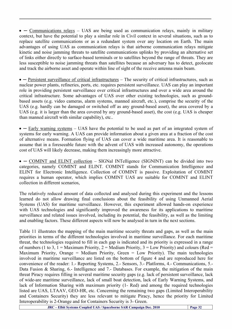
__________________________________________________________________________________
JRC ndash Elbit Systems Coupled UAS Spaceborne SAR Campaign Dec 2010 Page 32
bull Communications relays ndash UAS are being used as communication relays mainly in military context but have the potential to play a similar role in Civil context in several situations such as to replace satellite communications or as a redundant system over any location on Earth The main advantages of using UAS as communication relays is that airborne communication relays mitigate kinetic and noise jamming threats to satellite communications uplinks by providing an alternative set of links either directly to surface-based terminals or to satellites beyond the range of threats They are less susceptible to noise jamming threats than satellites because an adversary has to detect geolocate and track the airborne asset and operate within line of sight of the receive antenna main beam bull Persistent surveillance of critical infrastructures ndash The security of critical infrastructures such as nuclear power plants refineries ports etc requires persistent surveillance UAS can play an important role in providing persistent surveillance over critical infrastructures and over a wide area around the critical infrastructure Some advantages of UAS over other existing technologies such as ground-based assets (eg video cameras alarm systems manned aircraft etc) comprise the security of the UAS (eg hardly can be damaged or switched off as any ground-based asset) the area covered by a UAS (eg it is larger than the area covered by any ground-based asset) the cost (eg UAS is cheaper than manned aircraft with similar capability) etc bull Early warning systems ndash UAS have the potential to be used as part of an integrated system of systems for early warning A UAS can provide information about a given area at a fraction of the cost of alternative means Formation flying of UAS can cover a wide maritime area It is reasonable to assume that in a foreseeable future with the advent of UAS with increased autonomy the operations cost of UAS will likely decrease making them increasingly more attractive bull COMINT and ELINT collection ndash SIGNal INTelligence (SIGNINT) can be divided into two categories namely COMINT and ELINT COMINT stands for Communication Intelligence and ELINT for Electronic Intelligence Collection of COMINT is passive Exploitation of COMINT requires a human operator which implies COMINT UAS are suitable for COMINT and ELINT collection in different scenarios The relatively reduced amount of data collected and analysed during this experiment and the lessons learned do not allow drawing final conclusions about the feasibility of using Unmanned Aerial Systems (UAS) for maritime surveillance However this experiment allowed hands-on experience with UAS technologies and significantly improved the awareness for its applications to maritime surveillance and related issues involved including its potential the feasibility as well as the limiting and enabling factors These different aspects will now be analysed in turn in the next sections Table 11 illustrates the mapping of the main maritime security threats and gaps as well as the main priorities in terms of the different technologies involved in maritime surveillance For each maritime threat the technologies required to fill in each gap is indicated and its priority is expressed in a range of numbers (1 to 3 1 = Maximum Priority 2 = Medium Priority 3 = Low Priority) and colours (Red = Maximum Priority Orange = Medium Priority Green = Low Priority) The main technologies involved in maritime surveillance are listed on the bottom of figure 4 and are reproduced here for convenience of the reader 1- Reporting Systems 2- Sensors 3- Platforms 4- Communications 5- Data Fusion amp Sharing 6- Intelligence and 7- Databases For example the mitigation of the main threat Piracy requires filling in several maritime security gaps (eg lack of persistent surveillance lack of wide-are maritime surveillance lack of small boat detection lack of Early Warning Systems and lack of Information Sharing with maximum priority (1- Red) and among the required technologies listed are UAS LTAAV GEO-HR etc Concerning the remaining two gaps (Limited Interoperability and Containers Security) they are less relevant to mitigate Piracy hence the priority for Limited Interoperability is 2-Orange and for Containers Security is 3- Green
__________________________________________________________________________________ Table 9 ndash The Main Maritime Security and Safety Threats vs Gaps and the technologies that can be used to mitigate them
Maritime Security Main Threats GapsGapsrarr
darrThreats
Lack o f Risk As sessmentCapab ility
La ck of Persiste nt
Surveilla nce
La ck of Wid e-Area su rve illanc e
La ck of Small Boat De tecti on
Lack o f Earl y Warn ing Sys tems
L ack of In forma tion
Sh arin g
L imi ted In terop era bility
Lac k of Co ntai ners
Se cur ity
bull PiracyUAS LTAVG EO-
HR + UAS LT AVGEO-
HR + SAR GEO-HR
+ UAS USV LTAV
+ UAS LTAV
+ Coord in ationamp Sharing +
Inter opera bilityOptimisation +
1 2 3 5 6 7 1 2 3 5 6 7 1 2 3 5 6 1 2 3 123456 4567 1234567 1234567
bull Terro rismUAS LTAVG EO-
HR + UAS L TAV GEO-HR +
SAR AISGEO-HR +
UAS USV LTAV+
Intelligence+
Inte lligen ce+
Inter opera bilityOptimisation +
Intelligence+
1 2 3 5 6 7 1 2 3 5 6 1 2 3 5 6 1 2 3 123456 4567 1234567 1234567
bull Wea pon s ofM ass Dest ru ctio n Smugg ling
UAS LTAVG EO-HR +
UAS LT AVGEO-HR +
SAR AIS+
UAS USV LTAV+
Intelligence+
Inte lligen ce+
Intelligence+
Intelligence+
1 2 3 5 6 7 1 2 3 5 6 1 2 3 5 6 1 2 3 123456 4567 1234567 1234567
bull Drug sTraffic king
UAS LTAVG EO-HR +
UAS LT AVGEO-HR +
SAR AIS+
UAS USV LTAV+
Intelligence+
Inte lligen ce+
Intelligence+
Intelligence+
1 2 3 5 6 7 1 2 3 5 6 1 2 3 5 6 1 2 3 123456 4567 1234567 1234567
bull Illega lImmigratio n
UAS LTAVG EO-HR +
UAS LT AVGEO-HR +
SAR AIS+
UAS USV LTAV+
Intelligence+
Inte lligen ce+
Intelligence+
Intelligence+
1 2 3 5 6 7 1 2 3 5 6 1 2 3 5 6 1 2 3 123456 4567 1234567 1234567
bull Critic alI nfrastruc tureSecu rit y
UAS LTAVG EO-HR +
UAS LT AVGEO-HR +
SAR AIS+
UAS USV LTAV+ + Inte lligen ce
+ Intelligence
+ Intelligence
+
1 2 3 5 6 7 1 2 3 6 1 2 3 5 6 1 2 3 123456 4567 1234567 1234567
bull Illega lFish ing
UAS LTAVG EO-HR +
AI S+SAR UASLTAV +
SAR AIS GEO-HR+
UAS USV LTAV+
Intelligence+
Inte lligen ce+
Intelligence+
1 2 3 5 6 7 1 2 3 5 7 1 2 3 5 6 1 2 3 123456 4567 1234567
bull Un lawf ul Use of Co nta iners
(Secur ity)
UAS LTAVG EO-HR +
GPS Tr acking+
Intelligence+
Inte lligen ce+
GPS Int rusion Det ection Se al
1 2 3 5 6 7 4 6 7 1 2 3 5 6 1 2 3 123456 4567 1234567 1234567
(-) Priority (+) Not Rel evant
SURVEILLANCETECHNOLOGIES
1- Reporti ng Systems
2 -Sensors 3 -P latforms 4 - Communications 5- Data Fusionamp Sharing
6 -I ntelli gence 7 -Databases
JRC ndash Elbit Systems Coupled UAS Spaceborne SAR Campaign Dec 2010 Page 33
__________________________________________________________________________________
JRC ndash Elbit Systems Coupled UAS Spaceborne SAR Campaign Dec 2010 Page 34
61 ndash Hands-on experience with UAS technologies and its applications to maritime surveillance This coupled UASSpaceborne SAR campaign was a unique opportunity to acquire further handsndashon experience with UAS technologies and learn about the main issues related to its applications to maritime surveillance From the planning phase up to the execution of the UAS flight and landing there are several factors that need to be carefully analysed and taken into account A summary of the main issues identified in this experiment is given next 1- Selection of the Experiment Area Authorisation to Fly ndash For the time being UAS can only be flown in restricted areas usually under control of national authorities often the military This is due to the risks that a UAS can pose to human life and property In the present case an area under the authority of the Israeli Civil Aviation Authority was selected The authorisation to fly was not easy to obtain because the selected area is under the authority of the Civil Aviation Authority Figure 24 indicates the area of the experiment in Haifa Israel 2- UAS Communications Issues ndash The Hermes 450 was flown in Line-of-Sight (LOS) since it was close to the coast For BLOS (Beyond Line-of-Sight) operation satellite communications are required 3- Synthetic Aperture Radar (SAR) ndash The specific model Hermes 450W used in the experiment had no SAR sensor installed However a SAR sensor can be installed A SAR sensor is important for maritime surveillance since it allows 247 operations regardless of the weather conditions 4- Automatic Identification System (AIS) Receiver ndash The Hermes 450 used in this experiment was not equipped with an AIS receiver For maritime surveillance operations an AIS receiver is a very important tool since it allows the automatic identification of most ships allowing the UAS to concentrate on non-identified ships
__________________________________________________________________________________
Figure 24 ndash The area of the experiment is indicated by the GPS Trajectory of the UAV
62 ndash Potential of UAS for Maritime Surveillance UAS technologies are relatively recent and involve a wide range of fields spanning from aeronautics and sensors technologies to satellite communications and other engineering disciplines Innovations in each of the fields involved are emerging by the day UAS still have a long way to go before they become mature and their use fully operational For the time being UAS are mainly used for military applications However a large number of non-military UAS applications have been identified by stakeholders and there are several studies and demonstration flights foreseen for the near future Maritime surveillance is one of the most challenging and promising fields of application of UAS The challenges are due to the very demanding conditions under which the UAS must operate over sea and the requirements for safe operation
JRC ndash Elbit Systems Coupled UAS Spaceborne SAR Campaign Dec 2010 Page 35
__________________________________________________________________________________
JRC ndash Elbit Systems Coupled UAS Spaceborne SAR Campaign Dec 2010 Page 36
The present UAS experiment has unveiled some of the potential of UAS for maritime surveillance The UAS tests performed during this experiment include
1 ndash Detection of a Small rubber Boat and a Fishing Ship 2 ndash Tracking of a Small Boat and a Fishing Ship 3 ndash Classification of a Small Boat and a Fishing Ship 4 ndash Identification of a Small Boat and a Fishing Ship 5 ndash Detection and Tracking of People on the Beach
Despite the operational requirement that prevented the UAS from flying bellow 3km the experiment has confirmed the capability of UAS for small boat detection tracking and classification as well as the capability for people detection and tracking Concerning the identification of the targets the characteristics of the images acquired during this mission suggest that flying at lower altitudes the UAS images would allow the identification of the targets The UAS images can be seen from Figure 15 to 20
621 ndash Advantages of UAS for maritime Surveillance Some of the advantages of using UAS for maritime surveillance have been described in the literature and are summarized bellow
1- One potential benefit of UAS is that they could fill in a gap in current maritime surveillance by improving coverage
2- The range of UAS is a significant asset when compared to border agents on patrol or stationary surveillance equipment
3- Eletro-Optical InfraRed (EOIR) sensors (cameras) can identify small size objects from very high altitudes (high resolution)
4- UAS can provide precise and near-real-time imagery to a ground control operator who would then disseminate that information so that informed decisions regarding the deployment of border patrol agents can be made quickly
5- Long endurance UAS used along the border can fly for more than 30 hours up to several days without having to refuel compared with manned helicopterrsquos average flight time of just over 2 hours
6- The ability of UAS to loiter for prolonged periods of time has important operational advantages over manned aircraft
7- The longer flight times of UAS means that sustained coverage over a previously exposed area may improve maritime security
8- The range of UAVs is a significant asset when compared to border agents on patrol or stationary surveillance equipment Nevertheless the extended range and endurance of UAVs may lessen the burdens on human resources at the borders
9- UAS accidents do not risk the lives of pilots as do the helicopters and aircraft currently used by Coast Guards for border patrolling
__________________________________________________________________________________
JRC ndash Elbit Systems Coupled UAS Spaceborne SAR Campaign Dec 2010 Page 37
622 ndash Possible Drawbacks of using UAS for maritime Surveillance UAS also have disadvantages some of them are briefly described next
1- There have been concerns regarding the high accident rate of UAS which can be multiple times higher than that of manned aircraft Because UAS technology is still evolving there is less redundancy built into the operating system of UAS than of manned aircraft and until redundant systems are perfected mishap rates are expected to remain high
2- If control systems fail in a manned aircraft a well-trained pilot is better positioned to find the source of the problem because of hisher physical proximity If a UAS encountered a similar system failure or if a UAS landing was attempted during difficult weather conditions the ground control pilot would be at a disadvantage because he or she is removed from the event Unlike a manned pilot the remote pilot would not be able to assess important sensory information such as wind speed
3- Inclement weather conditions can also impinge on a UAS surveillance capability especially UAS equipped with only an EO camera and Forward Looking Infrared Radar (FLIR) because cloudy conditions and high humidity climates can distort the imagery produced by EO and FLIR equipment The effects of extreme climatic or atmospheric conditions on sensors reportedly can be mitigated with the outfit of one synthetic aperture radar (SAR) system and a moving target indicator (MTI) radar However adding SAR and MTI to a UAS platform would increase the costs associated with using UAS
4- Depending on the type of UAS the costs of operating a UAS can be higher than the costs of operating a manned aircraft This is because some types of UAS require a significant amount of logistical support and specialized operator and maintenance training Operating one UAS may require a crew of up to 20 support personnel The high comparative costs of operating some sophisticated types of UAS may be offset somewhat by their comparatively lower unit costs
63 ndash Main Limiting Factors Preventing the Use of UAS Several pre-requisites must be satisfied to render the UAS a viable cost-effective and regulated alternative to existing resources Major civil and commercial market barriers include
Single European Sky Sense and Avoid technologies Command and Control Technologies Reliability Communications (Bandwidth LOS BLOS)
Lack of airspace regulation that covers all types of UAV systems (encompassing lsquosense and avoidrsquo airspace integration and airworthiness issues)
Affordability - price and customization issues (eg commercial off-the-shelf open modular architecture) Lack of efforts to establish joint customer requirements (although this is gradually changing) Liability for civil operation Capacity for payload flexibility Lack of sufficient secure non-military frequencies for civil operation Perceived reliability (eg vehicle attrition rate vs manned aircraft) Operator training issues Recognitioncustomer perception of the UAV market Technology developments for multi-mission capability
__________________________________________________________________________________
64 ndash UAS Key Enabling Technologies Figure 25 illustrates the components of a typical UAV System showing some of the capabilities needed and the enabling technologies required for performing a given mission Any UAV mission involves many capabilities and technologies Due to the depicted system complexity the main key players such as the US Department of Defense (DoD) and other agencies have started to use the term Unmanned Aerial System (UAS) in place of UAV
Figure 25 ndash Unmanned Aerial Vehicle System Enabled by Autonomous Mission Management Reliable Flight Systems Navigation Accurate Systems Terrain Avoidance Power and Propulsion Some UAS key enabling technologies are listed below
Autonomous Mission Management Collision Avoidance Intelligent System Health Monitoring
Reliable Flight Systems Sophisticated Contingency Management Intelligent Data Handling and Processing Over-the-Horizon Communication Network-Centric Communication Open Architecture Power and Propulsion Navigation Accurate System Technology Enhanced Structures
JRC ndash Elbit Systems Coupled UAS Spaceborne SAR Campaign Dec 2010 Page 38
__________________________________________________________________________________
JRC ndash Elbit Systems Coupled UAS Spaceborne SAR Campaign Dec 2010 Page 39
Table 12 gives a more detailed description of other critical technologies for emerging autonomous UAV systems both civil and military Most of the technologies mentioned in Table 12 apply both to civil and military UAV systems Table 10 ndash Key Enabling Technologies (from SG75 study on autonomous systems)
Critical Technologies Decision Making Software
bull Fuzzy-based decision making bull Knowledge-based system bull Case-based reasoning bull Self-learning techniques bull Decision tree evaluation bull ReasoningInferring bull Probabilisticstochastic reasoning
Prediction Algorithms bull Predictive pathintent algorithms bull Short reaction algorithm bull Effectiveness evaluation
Status Assessment Software bull Internal status analysis bull Self-orientation
Situation Analysis Software bull Situation analysis bull Environmental analysis bull External status analysis
Modelling Software bull Air vehicle modelling algorithms bull Sensor modelling algorithms bull Scenario generation bull Threat system modeling bull Attack simulation bull Mission success optimisation model bull Simulation
Sensor Processing Software bull Sensor fusion bull Area of interest identification bull Automatic target recognition
Adaptive and Self-learning Systems bull Failure self-compensation
Attack Planning Software bull Attack plans and tactical alternatives bull Plan change impact identification
Weapon Engagement Procedure Software bull Weapon engagement algorithms
Mission Plan Update Software bull Route planning system bull Payload plan management system bull Mission Success Optimisation model
Path Optimisation Software bull Optimal trajectory planning bull Path Optimisation System
Targeting Software bull Target tracking bull Target prioritisation
Platform Technologies bull Obstacle detection and avoidance (airborne) bull Obstacle detection and avoidance (ground) bull Improved autopilot bull Speech recognition
Figure 26 summarises system element designs needed to transition from current to next-generation autonomous UAV systems for civilian and military UAS
__________________________________________________________________________________
Figure 26 ndash System Element Designs Needed to Transition from Current to Next-Generation Autonomous UAV Systems These new paradigms are a combination of system attributes and technological capabilities For instance the data fusion secure anti-jam and coordinated multi-vehicle control require technological development as well as specific system development to bring full maturity to unmanned systems Finally very small Micro UAVs (MAVs) and relatively large sophisticated UCAV systems are examples of the range of UAVs that are applying the new platforms payloads onboard processing communications etc to create next generation automated UAVs It is with these new platforms payloads etc that both UCAVs and MAV will be able to address similar operational challenges including
Mixed operation with other assets bull Deconfliction collision avoidance C4I integration
Operation over populated areas bull Safety issues Need to reduce reliance on communications bull UCAV ndash countermeasures bull MAV ndash limited size and power bull Limited line of sight environment Need a fully integrated system bull MAV propulsionpower generation still critical bull Operator machine interface critical bull All weather operations bull Survivability
JRC ndash Elbit Systems Coupled UAS Spaceborne SAR Campaign Dec 2010 Page 40
__________________________________________________________________________________
JRC ndash Elbit Systems Coupled UAS Spaceborne SAR Campaign Dec 2010 Page 41
65 ndash Mission Readiness
651 ndash Mission Readiness Summary This section summarises civil UAV mission readiness The purpose of Mission Readiness is to assess the readiness status of the different technologies involved in UAS In the present case this civil UAV mission readiness based on technology maturation forecasts that meet or exceed the desired or required capabilities identified by the user community Figure 27 summarises the mission readiness time forecasts for the different technologies The technologies annotated with an asterisk () are shown within the figure with maturation forecasts based on development targets expressed in the US Department of Defencesrsquo UAV Roadmap document The purpose of the chart is to be able to identify when the capability to fly a particular mission can be expected as a function of time The left-most end is the least probable and the right end the most probable timeframe
Figure 27 ndash Technology Maturation Summaries in Terms of Mission-Derived Capabilities
__________________________________________________________________________________
JRC ndash Elbit Systems Coupled UAS Spaceborne SAR Campaign Dec 2010 Page 42
66 ndash Small Boat Detection in SAR Satellite Imagery The use of spaceborne SAR imagery for small boat detection requires additional small boat detection experiments under different conditions using different methods It is not possible to draw final conclusions based on a limited number of small boat detection experiments which are not representative of the multiple possible scenarios
67 ndash Limitations of current State-of-the-Art SAR Satellite technology The main limitations of current State-of-the-Art spaceborne SAR imagery for maritime surveillance in particular aimed at small boat detection are 1 - SAR satellites repeat cycles do not allow the coverage of the same area at the required time intervals Constellations of SAR satellites could be a solution 2 - The conflict between resolution and image swath High resolution is required to detect small boats However the high resolution images have small swaths Maritime surveillance with high resolution images would require a large number of images to cover wide maritime areas which is very expensive and for the time being technically not feasible Intelligence data can play an important role by indicating an approximate position of suspicious non cooperative targets therefore reducing the surveillance area which can then be imaged using high resolution images 3- Spaceborne high resolution SAR imagery acquisition times are long enough to allow significant motion of the target during the acquisition time degrading the quality of the image Further research efforts are needed to develop new sensors and platforms As far as sensors are concerned shorter integration times are needed to prevent the blurring effect caused by the motion of the targets Regarding the platforms more platforms are needed to allow lower repeat cycles and improved coverage
__________________________________________________________________________________
JRC ndash Elbit Systems Coupled UAS Spaceborne SAR Campaign Dec 2010 Page 43
7 ndash Plans for Future Work The controlled experiments carried out by the EC-JRC together with Elbit Systems in Haifa-Israel comprised the deployment of a UAS (Hermes-450) and one small 12-meter boat A Radarsat-2 Spotlight image was acquired and several images collected by the Hermes-450 The experiment unveiled the potential of UAS for maritime surveillance in particular for detection tracking classification and possible identification of small targets The UAS was able to detect track and classify small targets such as small boats For low UAS altitude flights identification may be possible in some cases The small 12-meter boat was detected in the spaceborne SAR image The small boat detection trials carried out by the JRC were very successful since most small boats deployed during the experiments were detected in different sea states wind speeds and geographical locations The several small boat detection campaigns conducted by the EC-JRC seem to suggest that the probability of detection of small boats in spaceborne SAR images strongly depends on factors such as the sea state the wind speed the type of boat (shape and materials) the weather conditions among other factors The results of the experiments conducted thus far are not enough to draw final conclusions about the feasibility of using spaceborne SAR imagery for small boat detection However the experiments have an overall positive outcome because they indicate that under suitable sea state and wind speed conditions it is possible to detect small boats using spaceborne SAR The estimation of the probability of detection of small boats in spaceborne SAR images requires a large number of experiments under different circumstances (eg sea state wind speed characteristics of the targets image type and mode etc) Future plans include additional UAS experiments to asses its potential for maritime surveillance
Acknowledgements ndash The authors would like to express their gratitude to Elbit Systems for their cooperation logistical support and assets deployed without which the present coupled UASSAR Satellite Small Boat Detection Campaign would have not been possible
__________________________________________________________________________________
JRC ndash Elbit Systems Coupled UAS Spaceborne SAR Campaign Dec 2010 Page 44
REFERENCES [1] Elbit Systems ldquoUAV Elbit Systems Proposal for Unmanned Aerial Vehicle (UAV) flight to
collect Ground Truth data during a Maritime Surveillance Campaign and demonstrate UAV capabilities for Maritime Surveillancerdquo 2010
[2] ndash Cheryl Yuhas Suborbital Science Program Manager NASA Science Mission Directorate ldquoEarth Observations and the Role of UAVs A Capabilities Assessment Version 11rdquo Civil UAV Assessment Team httpwwwnasagovcentersdrydenresearchcivuavindexhtml August 2006
[3] ndash Document NIAG (SG75) NATO Industrial Advisory Group Study Group 75 Pre-Feasibility Study on UAV Autonomous Operations 2004
[4] ndash United States Department of Defence (DoD) Directive 50001 ldquoThe Defense Acquisition Systemrdquo and DoD Instruction 50002 ldquoOperation of the Defense Acquisition Systemrdquo
[5] ndash Mr James Ramage Mr Massimo Avalle Dr Erik Berglund Dr Luigi Crovella Mr Robert Frampton Dr Uwe Krogmann Mr Christian Ravat Mr Mike Robinson Dr Axel Schulte Dr Scott Wood ldquoRTO-TR-SCI-118 - Automation Technologies and Application Considerations for Highly Integrated Mission Systemsrdquo RTO-TR-SCI-118 AC323(SCI-118)TP204 January 2009
[6] Victor MG Silva Gilles Jurquet Gabriel Marchalot Maria TG Calzado Txema Soroa Juan Sancho Adam Koubek Harm Greidanus and Claudio Savarino ldquoWide Maritime Area Airborne Surveillance (WIMA2S) WP5 Final Reportrdquo WIMAAS WP5 FP7 Project 2008-2011 - ISBN-978-92-79-22801-8 (print) 978-92-79-22802-5 (PDF) ISSN-1018-5593 (print) 1831-9424 (online) EC-JRC Scientific Report JRC 70093 2012
[7] Victor MG Silva and Harm Greidanus ldquoSpaceborne SAR Small Boat Detection Campaign in Portugal and Spainrdquo EUR 25281 EN ISBN 978-92-79-22553-6 ISSN 1831-9424 (online) EC-JRC Scientific Report JRC68160 2012
[8] Goncalves Da Silva V Van Wimersma Greidanus H Hejmanowska B Loudjani P ldquoUAS Applications With Societal Benefits ndash JRCrsquos UAS-Related Activitiesrdquo 2011-2012 UAS Yearbook - UAS Unmanned Aircraft Systems - The Global Perspective 9 (9) 2011 p 127-129 JRC66600
[9] Goncalves Da Silva V Van Wimersma Greidanus H ldquoSmall boat detection using TerraSAR-X and Radarsat2 satellite imageryrdquo 4th TerraSAR-X Science Team Meeting 14 February 2011 DLR Oberpfaffenhofen (Germany) German Aerospace Center (DLR) (Organiser) 2011 JRC63663
[10] V Silva Harm Greidanus ldquoJRC - SAR Satellite Small Boat Detection Campaign - Portoroz ndash Sloveniardquo - ISBN-13 978-92-79-21476-9 ISSN (online) 1831-9424 EC-JRC Scientific Report JRC66835 2011
[11] V Silva Harm Greidanus ldquoJRC - SAR satellite small boat detection campaign - Algarve Portugalrdquo - ISBN-13 978-92-79-21265-9 ISSN (online) 1831-9424 ISSN (print) 1018-5593 EC-JRC Scientific Report JRC66631 2011
[12] ndash Goncalves Da Silva V Van Wimersma Greidanus H ldquoJRC-Frontex Spaceborne SAR Small Boat Detection Campaign ndash Italy amp Spainrdquo - ISBN-13 978-92-79-22213-9 ISSN (online) 1831-9424 EC-JRC Scientific Report JRC67517 2011
[13] - PW Vachon SJ Thomas J Cranton HR Edel and MD Henschel Validation of ship detection by the RADARSAT synthetic aperture radar and the Ocean Monitoring Workstation Canadian Journal of Remote Sensing 26(3)200ndash212 2000
[14] - Crisp D (2004) The state-of-the-art in ship detection in Synthetic Aperture Radar imagery DSTO Information Sciences Laboratory Australia
[15] - Joint Research Centre (JRC) of the European Community mdash IMPAST and DECLIMS web site httpintelligencejrcceceuintmarinefishindexhtm
[16] - McCandless SW Jackson CR (2004) Principles of Synthetic Aperture Radar Synthetic Aperture Radar Marine Users Manual NOAA Washington pp 1-23
[17] - Greidanus H (2008) Satellite Imaging for Maritime Surveillance of the European Seas Remote Sensing of the European Seas 343-358
European Commission
EUR 25346 EN --- Joint Research Centre --- Institute for the Protection and Security of the Citizen
Title JRC --- Elbit Systems Coupled UAS and Spaceborne SAR Campaign in Israel
Authors Victor MG Silva Harm Greidanus
Luxembourg Publications Office of the European Union
2012 --- v+44 pp --- 210 x 297 cm
EUR --- Scientific and Technical Research series --- ISSN 181-9424 (online) ISSN 1018-5593 (print)
ISBN 978-92-79-25020-0
doi10278828527
Abstract The European maritime area is one of Europersquos most important assets with regard to resources security and ultimately
prosperity of the Member States A significant part of Europersquos economy relies directly or indirectly on it It is not just the
shipping or fisheries industries and their related activities It is also shipbuilding and ports marine equipment and offshore
energy maritime and coastal tourism aquaculture submarine telecommunications blue biotech and the protection of the
marine environment The European maritime area faces several risks and threats posed by unlawful activities such as drugs
trafficking smuggling illegal immigration organised crime and terrorism Piracy in international waters also constitutes a threat
to Europe since it can disrupt the maritime transport chain These risks and threats can endanger human lives marine resources
and the environment as well as significantly disrupt the transport chain and global and local security It is anticipated that these
risks and threats will endure in the mid and long run In order to keep Europe as a world leader in the global maritime economy
an effective integratedinteroperable sustainable maritime surveillance system and situational awareness are needed
A significant number of unlawful maritime activities such as illegal immigration drugs trafficking smuggling piracy and
terrorism involve mainly small boats because small boats are faster and more difficult to detect using conventional means
Hence it is very important to find out the feasibility of using Unmanned Aerial Systems (UAS) for small boat detection tracking
classification and identification as well as to study the potential of UAS for maritime surveillance Since 2010 the EC-JRC has
carried out a number of UAS maritime surveillance campaigns to study the potential of UAS for maritime surveillance in
particular for small boat detection This report presents the results and conclusions of the JRC --- Elbit Systems Coupled UAS and
Spaceborne SAR campaign carried out in Dec 2010 in Haifa Israel
As the Commissionrsquos in-house science service the Joint Research Centrersquos mission is to provide EU policies with independent evidence-based scientific and technical support throughout the whole policy cycle Working in close cooperation with policy Directorates-General the JRC addresses key societal challenges while stimulating innovation through developing new standards methods and tools and sharing and transferring its know-how to the Member States and international community Key policy areas include environment and climate change energy and transport agriculture and food security health and consumer protection information society and digital agenda safety and security including nuclear all supported through a cross-cutting and multi-disciplinary approach
LB-NA-25346-EN
-N
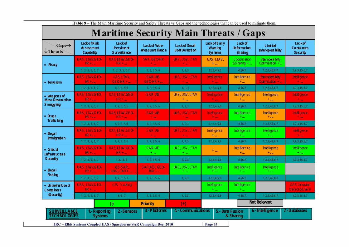
__________________________________________________________________________________
JRC ndash Elbit Systems Coupled UAS Spaceborne SAR Campaign Dec 2010 Page 34
61 ndash Hands-on experience with UAS technologies and its applications to maritime surveillance This coupled UASSpaceborne SAR campaign was a unique opportunity to acquire further handsndashon experience with UAS technologies and learn about the main issues related to its applications to maritime surveillance From the planning phase up to the execution of the UAS flight and landing there are several factors that need to be carefully analysed and taken into account A summary of the main issues identified in this experiment is given next 1- Selection of the Experiment Area Authorisation to Fly ndash For the time being UAS can only be flown in restricted areas usually under control of national authorities often the military This is due to the risks that a UAS can pose to human life and property In the present case an area under the authority of the Israeli Civil Aviation Authority was selected The authorisation to fly was not easy to obtain because the selected area is under the authority of the Civil Aviation Authority Figure 24 indicates the area of the experiment in Haifa Israel 2- UAS Communications Issues ndash The Hermes 450 was flown in Line-of-Sight (LOS) since it was close to the coast For BLOS (Beyond Line-of-Sight) operation satellite communications are required 3- Synthetic Aperture Radar (SAR) ndash The specific model Hermes 450W used in the experiment had no SAR sensor installed However a SAR sensor can be installed A SAR sensor is important for maritime surveillance since it allows 247 operations regardless of the weather conditions 4- Automatic Identification System (AIS) Receiver ndash The Hermes 450 used in this experiment was not equipped with an AIS receiver For maritime surveillance operations an AIS receiver is a very important tool since it allows the automatic identification of most ships allowing the UAS to concentrate on non-identified ships
__________________________________________________________________________________
Figure 24 ndash The area of the experiment is indicated by the GPS Trajectory of the UAV
62 ndash Potential of UAS for Maritime Surveillance UAS technologies are relatively recent and involve a wide range of fields spanning from aeronautics and sensors technologies to satellite communications and other engineering disciplines Innovations in each of the fields involved are emerging by the day UAS still have a long way to go before they become mature and their use fully operational For the time being UAS are mainly used for military applications However a large number of non-military UAS applications have been identified by stakeholders and there are several studies and demonstration flights foreseen for the near future Maritime surveillance is one of the most challenging and promising fields of application of UAS The challenges are due to the very demanding conditions under which the UAS must operate over sea and the requirements for safe operation
JRC ndash Elbit Systems Coupled UAS Spaceborne SAR Campaign Dec 2010 Page 35
__________________________________________________________________________________
JRC ndash Elbit Systems Coupled UAS Spaceborne SAR Campaign Dec 2010 Page 36
The present UAS experiment has unveiled some of the potential of UAS for maritime surveillance The UAS tests performed during this experiment include
1 ndash Detection of a Small rubber Boat and a Fishing Ship 2 ndash Tracking of a Small Boat and a Fishing Ship 3 ndash Classification of a Small Boat and a Fishing Ship 4 ndash Identification of a Small Boat and a Fishing Ship 5 ndash Detection and Tracking of People on the Beach
Despite the operational requirement that prevented the UAS from flying bellow 3km the experiment has confirmed the capability of UAS for small boat detection tracking and classification as well as the capability for people detection and tracking Concerning the identification of the targets the characteristics of the images acquired during this mission suggest that flying at lower altitudes the UAS images would allow the identification of the targets The UAS images can be seen from Figure 15 to 20
621 ndash Advantages of UAS for maritime Surveillance Some of the advantages of using UAS for maritime surveillance have been described in the literature and are summarized bellow
1- One potential benefit of UAS is that they could fill in a gap in current maritime surveillance by improving coverage
2- The range of UAS is a significant asset when compared to border agents on patrol or stationary surveillance equipment
3- Eletro-Optical InfraRed (EOIR) sensors (cameras) can identify small size objects from very high altitudes (high resolution)
4- UAS can provide precise and near-real-time imagery to a ground control operator who would then disseminate that information so that informed decisions regarding the deployment of border patrol agents can be made quickly
5- Long endurance UAS used along the border can fly for more than 30 hours up to several days without having to refuel compared with manned helicopterrsquos average flight time of just over 2 hours
6- The ability of UAS to loiter for prolonged periods of time has important operational advantages over manned aircraft
7- The longer flight times of UAS means that sustained coverage over a previously exposed area may improve maritime security
8- The range of UAVs is a significant asset when compared to border agents on patrol or stationary surveillance equipment Nevertheless the extended range and endurance of UAVs may lessen the burdens on human resources at the borders
9- UAS accidents do not risk the lives of pilots as do the helicopters and aircraft currently used by Coast Guards for border patrolling
__________________________________________________________________________________
JRC ndash Elbit Systems Coupled UAS Spaceborne SAR Campaign Dec 2010 Page 37
622 ndash Possible Drawbacks of using UAS for maritime Surveillance UAS also have disadvantages some of them are briefly described next
1- There have been concerns regarding the high accident rate of UAS which can be multiple times higher than that of manned aircraft Because UAS technology is still evolving there is less redundancy built into the operating system of UAS than of manned aircraft and until redundant systems are perfected mishap rates are expected to remain high
2- If control systems fail in a manned aircraft a well-trained pilot is better positioned to find the source of the problem because of hisher physical proximity If a UAS encountered a similar system failure or if a UAS landing was attempted during difficult weather conditions the ground control pilot would be at a disadvantage because he or she is removed from the event Unlike a manned pilot the remote pilot would not be able to assess important sensory information such as wind speed
3- Inclement weather conditions can also impinge on a UAS surveillance capability especially UAS equipped with only an EO camera and Forward Looking Infrared Radar (FLIR) because cloudy conditions and high humidity climates can distort the imagery produced by EO and FLIR equipment The effects of extreme climatic or atmospheric conditions on sensors reportedly can be mitigated with the outfit of one synthetic aperture radar (SAR) system and a moving target indicator (MTI) radar However adding SAR and MTI to a UAS platform would increase the costs associated with using UAS
4- Depending on the type of UAS the costs of operating a UAS can be higher than the costs of operating a manned aircraft This is because some types of UAS require a significant amount of logistical support and specialized operator and maintenance training Operating one UAS may require a crew of up to 20 support personnel The high comparative costs of operating some sophisticated types of UAS may be offset somewhat by their comparatively lower unit costs
63 ndash Main Limiting Factors Preventing the Use of UAS Several pre-requisites must be satisfied to render the UAS a viable cost-effective and regulated alternative to existing resources Major civil and commercial market barriers include
Single European Sky Sense and Avoid technologies Command and Control Technologies Reliability Communications (Bandwidth LOS BLOS)
Lack of airspace regulation that covers all types of UAV systems (encompassing lsquosense and avoidrsquo airspace integration and airworthiness issues)
Affordability - price and customization issues (eg commercial off-the-shelf open modular architecture) Lack of efforts to establish joint customer requirements (although this is gradually changing) Liability for civil operation Capacity for payload flexibility Lack of sufficient secure non-military frequencies for civil operation Perceived reliability (eg vehicle attrition rate vs manned aircraft) Operator training issues Recognitioncustomer perception of the UAV market Technology developments for multi-mission capability
__________________________________________________________________________________
64 ndash UAS Key Enabling Technologies Figure 25 illustrates the components of a typical UAV System showing some of the capabilities needed and the enabling technologies required for performing a given mission Any UAV mission involves many capabilities and technologies Due to the depicted system complexity the main key players such as the US Department of Defense (DoD) and other agencies have started to use the term Unmanned Aerial System (UAS) in place of UAV
Figure 25 ndash Unmanned Aerial Vehicle System Enabled by Autonomous Mission Management Reliable Flight Systems Navigation Accurate Systems Terrain Avoidance Power and Propulsion Some UAS key enabling technologies are listed below
Autonomous Mission Management Collision Avoidance Intelligent System Health Monitoring
Reliable Flight Systems Sophisticated Contingency Management Intelligent Data Handling and Processing Over-the-Horizon Communication Network-Centric Communication Open Architecture Power and Propulsion Navigation Accurate System Technology Enhanced Structures
JRC ndash Elbit Systems Coupled UAS Spaceborne SAR Campaign Dec 2010 Page 38
__________________________________________________________________________________
JRC ndash Elbit Systems Coupled UAS Spaceborne SAR Campaign Dec 2010 Page 39
Table 12 gives a more detailed description of other critical technologies for emerging autonomous UAV systems both civil and military Most of the technologies mentioned in Table 12 apply both to civil and military UAV systems Table 10 ndash Key Enabling Technologies (from SG75 study on autonomous systems)
Critical Technologies Decision Making Software
bull Fuzzy-based decision making bull Knowledge-based system bull Case-based reasoning bull Self-learning techniques bull Decision tree evaluation bull ReasoningInferring bull Probabilisticstochastic reasoning
Prediction Algorithms bull Predictive pathintent algorithms bull Short reaction algorithm bull Effectiveness evaluation
Status Assessment Software bull Internal status analysis bull Self-orientation
Situation Analysis Software bull Situation analysis bull Environmental analysis bull External status analysis
Modelling Software bull Air vehicle modelling algorithms bull Sensor modelling algorithms bull Scenario generation bull Threat system modeling bull Attack simulation bull Mission success optimisation model bull Simulation
Sensor Processing Software bull Sensor fusion bull Area of interest identification bull Automatic target recognition
Adaptive and Self-learning Systems bull Failure self-compensation
Attack Planning Software bull Attack plans and tactical alternatives bull Plan change impact identification
Weapon Engagement Procedure Software bull Weapon engagement algorithms
Mission Plan Update Software bull Route planning system bull Payload plan management system bull Mission Success Optimisation model
Path Optimisation Software bull Optimal trajectory planning bull Path Optimisation System
Targeting Software bull Target tracking bull Target prioritisation
Platform Technologies bull Obstacle detection and avoidance (airborne) bull Obstacle detection and avoidance (ground) bull Improved autopilot bull Speech recognition
Figure 26 summarises system element designs needed to transition from current to next-generation autonomous UAV systems for civilian and military UAS
__________________________________________________________________________________
Figure 26 ndash System Element Designs Needed to Transition from Current to Next-Generation Autonomous UAV Systems These new paradigms are a combination of system attributes and technological capabilities For instance the data fusion secure anti-jam and coordinated multi-vehicle control require technological development as well as specific system development to bring full maturity to unmanned systems Finally very small Micro UAVs (MAVs) and relatively large sophisticated UCAV systems are examples of the range of UAVs that are applying the new platforms payloads onboard processing communications etc to create next generation automated UAVs It is with these new platforms payloads etc that both UCAVs and MAV will be able to address similar operational challenges including
Mixed operation with other assets bull Deconfliction collision avoidance C4I integration
Operation over populated areas bull Safety issues Need to reduce reliance on communications bull UCAV ndash countermeasures bull MAV ndash limited size and power bull Limited line of sight environment Need a fully integrated system bull MAV propulsionpower generation still critical bull Operator machine interface critical bull All weather operations bull Survivability
JRC ndash Elbit Systems Coupled UAS Spaceborne SAR Campaign Dec 2010 Page 40
__________________________________________________________________________________
JRC ndash Elbit Systems Coupled UAS Spaceborne SAR Campaign Dec 2010 Page 41
65 ndash Mission Readiness
651 ndash Mission Readiness Summary This section summarises civil UAV mission readiness The purpose of Mission Readiness is to assess the readiness status of the different technologies involved in UAS In the present case this civil UAV mission readiness based on technology maturation forecasts that meet or exceed the desired or required capabilities identified by the user community Figure 27 summarises the mission readiness time forecasts for the different technologies The technologies annotated with an asterisk () are shown within the figure with maturation forecasts based on development targets expressed in the US Department of Defencesrsquo UAV Roadmap document The purpose of the chart is to be able to identify when the capability to fly a particular mission can be expected as a function of time The left-most end is the least probable and the right end the most probable timeframe
Figure 27 ndash Technology Maturation Summaries in Terms of Mission-Derived Capabilities
__________________________________________________________________________________
JRC ndash Elbit Systems Coupled UAS Spaceborne SAR Campaign Dec 2010 Page 42
66 ndash Small Boat Detection in SAR Satellite Imagery The use of spaceborne SAR imagery for small boat detection requires additional small boat detection experiments under different conditions using different methods It is not possible to draw final conclusions based on a limited number of small boat detection experiments which are not representative of the multiple possible scenarios
67 ndash Limitations of current State-of-the-Art SAR Satellite technology The main limitations of current State-of-the-Art spaceborne SAR imagery for maritime surveillance in particular aimed at small boat detection are 1 - SAR satellites repeat cycles do not allow the coverage of the same area at the required time intervals Constellations of SAR satellites could be a solution 2 - The conflict between resolution and image swath High resolution is required to detect small boats However the high resolution images have small swaths Maritime surveillance with high resolution images would require a large number of images to cover wide maritime areas which is very expensive and for the time being technically not feasible Intelligence data can play an important role by indicating an approximate position of suspicious non cooperative targets therefore reducing the surveillance area which can then be imaged using high resolution images 3- Spaceborne high resolution SAR imagery acquisition times are long enough to allow significant motion of the target during the acquisition time degrading the quality of the image Further research efforts are needed to develop new sensors and platforms As far as sensors are concerned shorter integration times are needed to prevent the blurring effect caused by the motion of the targets Regarding the platforms more platforms are needed to allow lower repeat cycles and improved coverage
__________________________________________________________________________________
JRC ndash Elbit Systems Coupled UAS Spaceborne SAR Campaign Dec 2010 Page 43
7 ndash Plans for Future Work The controlled experiments carried out by the EC-JRC together with Elbit Systems in Haifa-Israel comprised the deployment of a UAS (Hermes-450) and one small 12-meter boat A Radarsat-2 Spotlight image was acquired and several images collected by the Hermes-450 The experiment unveiled the potential of UAS for maritime surveillance in particular for detection tracking classification and possible identification of small targets The UAS was able to detect track and classify small targets such as small boats For low UAS altitude flights identification may be possible in some cases The small 12-meter boat was detected in the spaceborne SAR image The small boat detection trials carried out by the JRC were very successful since most small boats deployed during the experiments were detected in different sea states wind speeds and geographical locations The several small boat detection campaigns conducted by the EC-JRC seem to suggest that the probability of detection of small boats in spaceborne SAR images strongly depends on factors such as the sea state the wind speed the type of boat (shape and materials) the weather conditions among other factors The results of the experiments conducted thus far are not enough to draw final conclusions about the feasibility of using spaceborne SAR imagery for small boat detection However the experiments have an overall positive outcome because they indicate that under suitable sea state and wind speed conditions it is possible to detect small boats using spaceborne SAR The estimation of the probability of detection of small boats in spaceborne SAR images requires a large number of experiments under different circumstances (eg sea state wind speed characteristics of the targets image type and mode etc) Future plans include additional UAS experiments to asses its potential for maritime surveillance
Acknowledgements ndash The authors would like to express their gratitude to Elbit Systems for their cooperation logistical support and assets deployed without which the present coupled UASSAR Satellite Small Boat Detection Campaign would have not been possible
__________________________________________________________________________________
JRC ndash Elbit Systems Coupled UAS Spaceborne SAR Campaign Dec 2010 Page 44
REFERENCES [1] Elbit Systems ldquoUAV Elbit Systems Proposal for Unmanned Aerial Vehicle (UAV) flight to
collect Ground Truth data during a Maritime Surveillance Campaign and demonstrate UAV capabilities for Maritime Surveillancerdquo 2010
[2] ndash Cheryl Yuhas Suborbital Science Program Manager NASA Science Mission Directorate ldquoEarth Observations and the Role of UAVs A Capabilities Assessment Version 11rdquo Civil UAV Assessment Team httpwwwnasagovcentersdrydenresearchcivuavindexhtml August 2006
[3] ndash Document NIAG (SG75) NATO Industrial Advisory Group Study Group 75 Pre-Feasibility Study on UAV Autonomous Operations 2004
[4] ndash United States Department of Defence (DoD) Directive 50001 ldquoThe Defense Acquisition Systemrdquo and DoD Instruction 50002 ldquoOperation of the Defense Acquisition Systemrdquo
[5] ndash Mr James Ramage Mr Massimo Avalle Dr Erik Berglund Dr Luigi Crovella Mr Robert Frampton Dr Uwe Krogmann Mr Christian Ravat Mr Mike Robinson Dr Axel Schulte Dr Scott Wood ldquoRTO-TR-SCI-118 - Automation Technologies and Application Considerations for Highly Integrated Mission Systemsrdquo RTO-TR-SCI-118 AC323(SCI-118)TP204 January 2009
[6] Victor MG Silva Gilles Jurquet Gabriel Marchalot Maria TG Calzado Txema Soroa Juan Sancho Adam Koubek Harm Greidanus and Claudio Savarino ldquoWide Maritime Area Airborne Surveillance (WIMA2S) WP5 Final Reportrdquo WIMAAS WP5 FP7 Project 2008-2011 - ISBN-978-92-79-22801-8 (print) 978-92-79-22802-5 (PDF) ISSN-1018-5593 (print) 1831-9424 (online) EC-JRC Scientific Report JRC 70093 2012
[7] Victor MG Silva and Harm Greidanus ldquoSpaceborne SAR Small Boat Detection Campaign in Portugal and Spainrdquo EUR 25281 EN ISBN 978-92-79-22553-6 ISSN 1831-9424 (online) EC-JRC Scientific Report JRC68160 2012
[8] Goncalves Da Silva V Van Wimersma Greidanus H Hejmanowska B Loudjani P ldquoUAS Applications With Societal Benefits ndash JRCrsquos UAS-Related Activitiesrdquo 2011-2012 UAS Yearbook - UAS Unmanned Aircraft Systems - The Global Perspective 9 (9) 2011 p 127-129 JRC66600
[9] Goncalves Da Silva V Van Wimersma Greidanus H ldquoSmall boat detection using TerraSAR-X and Radarsat2 satellite imageryrdquo 4th TerraSAR-X Science Team Meeting 14 February 2011 DLR Oberpfaffenhofen (Germany) German Aerospace Center (DLR) (Organiser) 2011 JRC63663
[10] V Silva Harm Greidanus ldquoJRC - SAR Satellite Small Boat Detection Campaign - Portoroz ndash Sloveniardquo - ISBN-13 978-92-79-21476-9 ISSN (online) 1831-9424 EC-JRC Scientific Report JRC66835 2011
[11] V Silva Harm Greidanus ldquoJRC - SAR satellite small boat detection campaign - Algarve Portugalrdquo - ISBN-13 978-92-79-21265-9 ISSN (online) 1831-9424 ISSN (print) 1018-5593 EC-JRC Scientific Report JRC66631 2011
[12] ndash Goncalves Da Silva V Van Wimersma Greidanus H ldquoJRC-Frontex Spaceborne SAR Small Boat Detection Campaign ndash Italy amp Spainrdquo - ISBN-13 978-92-79-22213-9 ISSN (online) 1831-9424 EC-JRC Scientific Report JRC67517 2011
[13] - PW Vachon SJ Thomas J Cranton HR Edel and MD Henschel Validation of ship detection by the RADARSAT synthetic aperture radar and the Ocean Monitoring Workstation Canadian Journal of Remote Sensing 26(3)200ndash212 2000
[14] - Crisp D (2004) The state-of-the-art in ship detection in Synthetic Aperture Radar imagery DSTO Information Sciences Laboratory Australia
[15] - Joint Research Centre (JRC) of the European Community mdash IMPAST and DECLIMS web site httpintelligencejrcceceuintmarinefishindexhtm
[16] - McCandless SW Jackson CR (2004) Principles of Synthetic Aperture Radar Synthetic Aperture Radar Marine Users Manual NOAA Washington pp 1-23
[17] - Greidanus H (2008) Satellite Imaging for Maritime Surveillance of the European Seas Remote Sensing of the European Seas 343-358
European Commission
EUR 25346 EN --- Joint Research Centre --- Institute for the Protection and Security of the Citizen
Title JRC --- Elbit Systems Coupled UAS and Spaceborne SAR Campaign in Israel
Authors Victor MG Silva Harm Greidanus
Luxembourg Publications Office of the European Union
2012 --- v+44 pp --- 210 x 297 cm
EUR --- Scientific and Technical Research series --- ISSN 181-9424 (online) ISSN 1018-5593 (print)
ISBN 978-92-79-25020-0
doi10278828527
Abstract The European maritime area is one of Europersquos most important assets with regard to resources security and ultimately
prosperity of the Member States A significant part of Europersquos economy relies directly or indirectly on it It is not just the
shipping or fisheries industries and their related activities It is also shipbuilding and ports marine equipment and offshore
energy maritime and coastal tourism aquaculture submarine telecommunications blue biotech and the protection of the
marine environment The European maritime area faces several risks and threats posed by unlawful activities such as drugs
trafficking smuggling illegal immigration organised crime and terrorism Piracy in international waters also constitutes a threat
to Europe since it can disrupt the maritime transport chain These risks and threats can endanger human lives marine resources
and the environment as well as significantly disrupt the transport chain and global and local security It is anticipated that these
risks and threats will endure in the mid and long run In order to keep Europe as a world leader in the global maritime economy
an effective integratedinteroperable sustainable maritime surveillance system and situational awareness are needed
A significant number of unlawful maritime activities such as illegal immigration drugs trafficking smuggling piracy and
terrorism involve mainly small boats because small boats are faster and more difficult to detect using conventional means
Hence it is very important to find out the feasibility of using Unmanned Aerial Systems (UAS) for small boat detection tracking
classification and identification as well as to study the potential of UAS for maritime surveillance Since 2010 the EC-JRC has
carried out a number of UAS maritime surveillance campaigns to study the potential of UAS for maritime surveillance in
particular for small boat detection This report presents the results and conclusions of the JRC --- Elbit Systems Coupled UAS and
Spaceborne SAR campaign carried out in Dec 2010 in Haifa Israel
As the Commissionrsquos in-house science service the Joint Research Centrersquos mission is to provide EU policies with independent evidence-based scientific and technical support throughout the whole policy cycle Working in close cooperation with policy Directorates-General the JRC addresses key societal challenges while stimulating innovation through developing new standards methods and tools and sharing and transferring its know-how to the Member States and international community Key policy areas include environment and climate change energy and transport agriculture and food security health and consumer protection information society and digital agenda safety and security including nuclear all supported through a cross-cutting and multi-disciplinary approach
LB-NA-25346-EN
-N
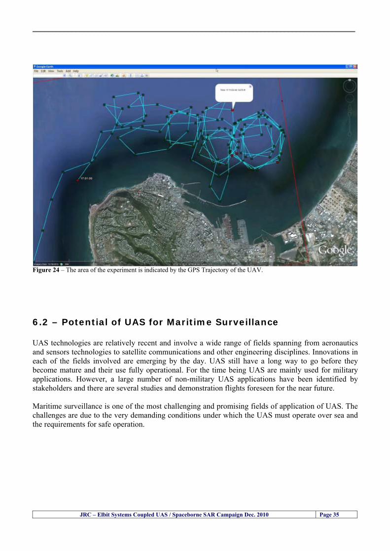
__________________________________________________________________________________
Figure 24 ndash The area of the experiment is indicated by the GPS Trajectory of the UAV
62 ndash Potential of UAS for Maritime Surveillance UAS technologies are relatively recent and involve a wide range of fields spanning from aeronautics and sensors technologies to satellite communications and other engineering disciplines Innovations in each of the fields involved are emerging by the day UAS still have a long way to go before they become mature and their use fully operational For the time being UAS are mainly used for military applications However a large number of non-military UAS applications have been identified by stakeholders and there are several studies and demonstration flights foreseen for the near future Maritime surveillance is one of the most challenging and promising fields of application of UAS The challenges are due to the very demanding conditions under which the UAS must operate over sea and the requirements for safe operation
JRC ndash Elbit Systems Coupled UAS Spaceborne SAR Campaign Dec 2010 Page 35
__________________________________________________________________________________
JRC ndash Elbit Systems Coupled UAS Spaceborne SAR Campaign Dec 2010 Page 36
The present UAS experiment has unveiled some of the potential of UAS for maritime surveillance The UAS tests performed during this experiment include
1 ndash Detection of a Small rubber Boat and a Fishing Ship 2 ndash Tracking of a Small Boat and a Fishing Ship 3 ndash Classification of a Small Boat and a Fishing Ship 4 ndash Identification of a Small Boat and a Fishing Ship 5 ndash Detection and Tracking of People on the Beach
Despite the operational requirement that prevented the UAS from flying bellow 3km the experiment has confirmed the capability of UAS for small boat detection tracking and classification as well as the capability for people detection and tracking Concerning the identification of the targets the characteristics of the images acquired during this mission suggest that flying at lower altitudes the UAS images would allow the identification of the targets The UAS images can be seen from Figure 15 to 20
621 ndash Advantages of UAS for maritime Surveillance Some of the advantages of using UAS for maritime surveillance have been described in the literature and are summarized bellow
1- One potential benefit of UAS is that they could fill in a gap in current maritime surveillance by improving coverage
2- The range of UAS is a significant asset when compared to border agents on patrol or stationary surveillance equipment
3- Eletro-Optical InfraRed (EOIR) sensors (cameras) can identify small size objects from very high altitudes (high resolution)
4- UAS can provide precise and near-real-time imagery to a ground control operator who would then disseminate that information so that informed decisions regarding the deployment of border patrol agents can be made quickly
5- Long endurance UAS used along the border can fly for more than 30 hours up to several days without having to refuel compared with manned helicopterrsquos average flight time of just over 2 hours
6- The ability of UAS to loiter for prolonged periods of time has important operational advantages over manned aircraft
7- The longer flight times of UAS means that sustained coverage over a previously exposed area may improve maritime security
8- The range of UAVs is a significant asset when compared to border agents on patrol or stationary surveillance equipment Nevertheless the extended range and endurance of UAVs may lessen the burdens on human resources at the borders
9- UAS accidents do not risk the lives of pilots as do the helicopters and aircraft currently used by Coast Guards for border patrolling
__________________________________________________________________________________
JRC ndash Elbit Systems Coupled UAS Spaceborne SAR Campaign Dec 2010 Page 37
622 ndash Possible Drawbacks of using UAS for maritime Surveillance UAS also have disadvantages some of them are briefly described next
1- There have been concerns regarding the high accident rate of UAS which can be multiple times higher than that of manned aircraft Because UAS technology is still evolving there is less redundancy built into the operating system of UAS than of manned aircraft and until redundant systems are perfected mishap rates are expected to remain high
2- If control systems fail in a manned aircraft a well-trained pilot is better positioned to find the source of the problem because of hisher physical proximity If a UAS encountered a similar system failure or if a UAS landing was attempted during difficult weather conditions the ground control pilot would be at a disadvantage because he or she is removed from the event Unlike a manned pilot the remote pilot would not be able to assess important sensory information such as wind speed
3- Inclement weather conditions can also impinge on a UAS surveillance capability especially UAS equipped with only an EO camera and Forward Looking Infrared Radar (FLIR) because cloudy conditions and high humidity climates can distort the imagery produced by EO and FLIR equipment The effects of extreme climatic or atmospheric conditions on sensors reportedly can be mitigated with the outfit of one synthetic aperture radar (SAR) system and a moving target indicator (MTI) radar However adding SAR and MTI to a UAS platform would increase the costs associated with using UAS
4- Depending on the type of UAS the costs of operating a UAS can be higher than the costs of operating a manned aircraft This is because some types of UAS require a significant amount of logistical support and specialized operator and maintenance training Operating one UAS may require a crew of up to 20 support personnel The high comparative costs of operating some sophisticated types of UAS may be offset somewhat by their comparatively lower unit costs
63 ndash Main Limiting Factors Preventing the Use of UAS Several pre-requisites must be satisfied to render the UAS a viable cost-effective and regulated alternative to existing resources Major civil and commercial market barriers include
Single European Sky Sense and Avoid technologies Command and Control Technologies Reliability Communications (Bandwidth LOS BLOS)
Lack of airspace regulation that covers all types of UAV systems (encompassing lsquosense and avoidrsquo airspace integration and airworthiness issues)
Affordability - price and customization issues (eg commercial off-the-shelf open modular architecture) Lack of efforts to establish joint customer requirements (although this is gradually changing) Liability for civil operation Capacity for payload flexibility Lack of sufficient secure non-military frequencies for civil operation Perceived reliability (eg vehicle attrition rate vs manned aircraft) Operator training issues Recognitioncustomer perception of the UAV market Technology developments for multi-mission capability
__________________________________________________________________________________
64 ndash UAS Key Enabling Technologies Figure 25 illustrates the components of a typical UAV System showing some of the capabilities needed and the enabling technologies required for performing a given mission Any UAV mission involves many capabilities and technologies Due to the depicted system complexity the main key players such as the US Department of Defense (DoD) and other agencies have started to use the term Unmanned Aerial System (UAS) in place of UAV
Figure 25 ndash Unmanned Aerial Vehicle System Enabled by Autonomous Mission Management Reliable Flight Systems Navigation Accurate Systems Terrain Avoidance Power and Propulsion Some UAS key enabling technologies are listed below
Autonomous Mission Management Collision Avoidance Intelligent System Health Monitoring
Reliable Flight Systems Sophisticated Contingency Management Intelligent Data Handling and Processing Over-the-Horizon Communication Network-Centric Communication Open Architecture Power and Propulsion Navigation Accurate System Technology Enhanced Structures
JRC ndash Elbit Systems Coupled UAS Spaceborne SAR Campaign Dec 2010 Page 38
__________________________________________________________________________________
JRC ndash Elbit Systems Coupled UAS Spaceborne SAR Campaign Dec 2010 Page 39
Table 12 gives a more detailed description of other critical technologies for emerging autonomous UAV systems both civil and military Most of the technologies mentioned in Table 12 apply both to civil and military UAV systems Table 10 ndash Key Enabling Technologies (from SG75 study on autonomous systems)
Critical Technologies Decision Making Software
bull Fuzzy-based decision making bull Knowledge-based system bull Case-based reasoning bull Self-learning techniques bull Decision tree evaluation bull ReasoningInferring bull Probabilisticstochastic reasoning
Prediction Algorithms bull Predictive pathintent algorithms bull Short reaction algorithm bull Effectiveness evaluation
Status Assessment Software bull Internal status analysis bull Self-orientation
Situation Analysis Software bull Situation analysis bull Environmental analysis bull External status analysis
Modelling Software bull Air vehicle modelling algorithms bull Sensor modelling algorithms bull Scenario generation bull Threat system modeling bull Attack simulation bull Mission success optimisation model bull Simulation
Sensor Processing Software bull Sensor fusion bull Area of interest identification bull Automatic target recognition
Adaptive and Self-learning Systems bull Failure self-compensation
Attack Planning Software bull Attack plans and tactical alternatives bull Plan change impact identification
Weapon Engagement Procedure Software bull Weapon engagement algorithms
Mission Plan Update Software bull Route planning system bull Payload plan management system bull Mission Success Optimisation model
Path Optimisation Software bull Optimal trajectory planning bull Path Optimisation System
Targeting Software bull Target tracking bull Target prioritisation
Platform Technologies bull Obstacle detection and avoidance (airborne) bull Obstacle detection and avoidance (ground) bull Improved autopilot bull Speech recognition
Figure 26 summarises system element designs needed to transition from current to next-generation autonomous UAV systems for civilian and military UAS
__________________________________________________________________________________
Figure 26 ndash System Element Designs Needed to Transition from Current to Next-Generation Autonomous UAV Systems These new paradigms are a combination of system attributes and technological capabilities For instance the data fusion secure anti-jam and coordinated multi-vehicle control require technological development as well as specific system development to bring full maturity to unmanned systems Finally very small Micro UAVs (MAVs) and relatively large sophisticated UCAV systems are examples of the range of UAVs that are applying the new platforms payloads onboard processing communications etc to create next generation automated UAVs It is with these new platforms payloads etc that both UCAVs and MAV will be able to address similar operational challenges including
Mixed operation with other assets bull Deconfliction collision avoidance C4I integration
Operation over populated areas bull Safety issues Need to reduce reliance on communications bull UCAV ndash countermeasures bull MAV ndash limited size and power bull Limited line of sight environment Need a fully integrated system bull MAV propulsionpower generation still critical bull Operator machine interface critical bull All weather operations bull Survivability
JRC ndash Elbit Systems Coupled UAS Spaceborne SAR Campaign Dec 2010 Page 40
__________________________________________________________________________________
JRC ndash Elbit Systems Coupled UAS Spaceborne SAR Campaign Dec 2010 Page 41
65 ndash Mission Readiness
651 ndash Mission Readiness Summary This section summarises civil UAV mission readiness The purpose of Mission Readiness is to assess the readiness status of the different technologies involved in UAS In the present case this civil UAV mission readiness based on technology maturation forecasts that meet or exceed the desired or required capabilities identified by the user community Figure 27 summarises the mission readiness time forecasts for the different technologies The technologies annotated with an asterisk () are shown within the figure with maturation forecasts based on development targets expressed in the US Department of Defencesrsquo UAV Roadmap document The purpose of the chart is to be able to identify when the capability to fly a particular mission can be expected as a function of time The left-most end is the least probable and the right end the most probable timeframe
Figure 27 ndash Technology Maturation Summaries in Terms of Mission-Derived Capabilities
__________________________________________________________________________________
JRC ndash Elbit Systems Coupled UAS Spaceborne SAR Campaign Dec 2010 Page 42
66 ndash Small Boat Detection in SAR Satellite Imagery The use of spaceborne SAR imagery for small boat detection requires additional small boat detection experiments under different conditions using different methods It is not possible to draw final conclusions based on a limited number of small boat detection experiments which are not representative of the multiple possible scenarios
67 ndash Limitations of current State-of-the-Art SAR Satellite technology The main limitations of current State-of-the-Art spaceborne SAR imagery for maritime surveillance in particular aimed at small boat detection are 1 - SAR satellites repeat cycles do not allow the coverage of the same area at the required time intervals Constellations of SAR satellites could be a solution 2 - The conflict between resolution and image swath High resolution is required to detect small boats However the high resolution images have small swaths Maritime surveillance with high resolution images would require a large number of images to cover wide maritime areas which is very expensive and for the time being technically not feasible Intelligence data can play an important role by indicating an approximate position of suspicious non cooperative targets therefore reducing the surveillance area which can then be imaged using high resolution images 3- Spaceborne high resolution SAR imagery acquisition times are long enough to allow significant motion of the target during the acquisition time degrading the quality of the image Further research efforts are needed to develop new sensors and platforms As far as sensors are concerned shorter integration times are needed to prevent the blurring effect caused by the motion of the targets Regarding the platforms more platforms are needed to allow lower repeat cycles and improved coverage
__________________________________________________________________________________
JRC ndash Elbit Systems Coupled UAS Spaceborne SAR Campaign Dec 2010 Page 43
7 ndash Plans for Future Work The controlled experiments carried out by the EC-JRC together with Elbit Systems in Haifa-Israel comprised the deployment of a UAS (Hermes-450) and one small 12-meter boat A Radarsat-2 Spotlight image was acquired and several images collected by the Hermes-450 The experiment unveiled the potential of UAS for maritime surveillance in particular for detection tracking classification and possible identification of small targets The UAS was able to detect track and classify small targets such as small boats For low UAS altitude flights identification may be possible in some cases The small 12-meter boat was detected in the spaceborne SAR image The small boat detection trials carried out by the JRC were very successful since most small boats deployed during the experiments were detected in different sea states wind speeds and geographical locations The several small boat detection campaigns conducted by the EC-JRC seem to suggest that the probability of detection of small boats in spaceborne SAR images strongly depends on factors such as the sea state the wind speed the type of boat (shape and materials) the weather conditions among other factors The results of the experiments conducted thus far are not enough to draw final conclusions about the feasibility of using spaceborne SAR imagery for small boat detection However the experiments have an overall positive outcome because they indicate that under suitable sea state and wind speed conditions it is possible to detect small boats using spaceborne SAR The estimation of the probability of detection of small boats in spaceborne SAR images requires a large number of experiments under different circumstances (eg sea state wind speed characteristics of the targets image type and mode etc) Future plans include additional UAS experiments to asses its potential for maritime surveillance
Acknowledgements ndash The authors would like to express their gratitude to Elbit Systems for their cooperation logistical support and assets deployed without which the present coupled UASSAR Satellite Small Boat Detection Campaign would have not been possible
__________________________________________________________________________________
JRC ndash Elbit Systems Coupled UAS Spaceborne SAR Campaign Dec 2010 Page 44
REFERENCES [1] Elbit Systems ldquoUAV Elbit Systems Proposal for Unmanned Aerial Vehicle (UAV) flight to
collect Ground Truth data during a Maritime Surveillance Campaign and demonstrate UAV capabilities for Maritime Surveillancerdquo 2010
[2] ndash Cheryl Yuhas Suborbital Science Program Manager NASA Science Mission Directorate ldquoEarth Observations and the Role of UAVs A Capabilities Assessment Version 11rdquo Civil UAV Assessment Team httpwwwnasagovcentersdrydenresearchcivuavindexhtml August 2006
[3] ndash Document NIAG (SG75) NATO Industrial Advisory Group Study Group 75 Pre-Feasibility Study on UAV Autonomous Operations 2004
[4] ndash United States Department of Defence (DoD) Directive 50001 ldquoThe Defense Acquisition Systemrdquo and DoD Instruction 50002 ldquoOperation of the Defense Acquisition Systemrdquo
[5] ndash Mr James Ramage Mr Massimo Avalle Dr Erik Berglund Dr Luigi Crovella Mr Robert Frampton Dr Uwe Krogmann Mr Christian Ravat Mr Mike Robinson Dr Axel Schulte Dr Scott Wood ldquoRTO-TR-SCI-118 - Automation Technologies and Application Considerations for Highly Integrated Mission Systemsrdquo RTO-TR-SCI-118 AC323(SCI-118)TP204 January 2009
[6] Victor MG Silva Gilles Jurquet Gabriel Marchalot Maria TG Calzado Txema Soroa Juan Sancho Adam Koubek Harm Greidanus and Claudio Savarino ldquoWide Maritime Area Airborne Surveillance (WIMA2S) WP5 Final Reportrdquo WIMAAS WP5 FP7 Project 2008-2011 - ISBN-978-92-79-22801-8 (print) 978-92-79-22802-5 (PDF) ISSN-1018-5593 (print) 1831-9424 (online) EC-JRC Scientific Report JRC 70093 2012
[7] Victor MG Silva and Harm Greidanus ldquoSpaceborne SAR Small Boat Detection Campaign in Portugal and Spainrdquo EUR 25281 EN ISBN 978-92-79-22553-6 ISSN 1831-9424 (online) EC-JRC Scientific Report JRC68160 2012
[8] Goncalves Da Silva V Van Wimersma Greidanus H Hejmanowska B Loudjani P ldquoUAS Applications With Societal Benefits ndash JRCrsquos UAS-Related Activitiesrdquo 2011-2012 UAS Yearbook - UAS Unmanned Aircraft Systems - The Global Perspective 9 (9) 2011 p 127-129 JRC66600
[9] Goncalves Da Silva V Van Wimersma Greidanus H ldquoSmall boat detection using TerraSAR-X and Radarsat2 satellite imageryrdquo 4th TerraSAR-X Science Team Meeting 14 February 2011 DLR Oberpfaffenhofen (Germany) German Aerospace Center (DLR) (Organiser) 2011 JRC63663
[10] V Silva Harm Greidanus ldquoJRC - SAR Satellite Small Boat Detection Campaign - Portoroz ndash Sloveniardquo - ISBN-13 978-92-79-21476-9 ISSN (online) 1831-9424 EC-JRC Scientific Report JRC66835 2011
[11] V Silva Harm Greidanus ldquoJRC - SAR satellite small boat detection campaign - Algarve Portugalrdquo - ISBN-13 978-92-79-21265-9 ISSN (online) 1831-9424 ISSN (print) 1018-5593 EC-JRC Scientific Report JRC66631 2011
[12] ndash Goncalves Da Silva V Van Wimersma Greidanus H ldquoJRC-Frontex Spaceborne SAR Small Boat Detection Campaign ndash Italy amp Spainrdquo - ISBN-13 978-92-79-22213-9 ISSN (online) 1831-9424 EC-JRC Scientific Report JRC67517 2011
[13] - PW Vachon SJ Thomas J Cranton HR Edel and MD Henschel Validation of ship detection by the RADARSAT synthetic aperture radar and the Ocean Monitoring Workstation Canadian Journal of Remote Sensing 26(3)200ndash212 2000
[14] - Crisp D (2004) The state-of-the-art in ship detection in Synthetic Aperture Radar imagery DSTO Information Sciences Laboratory Australia
[15] - Joint Research Centre (JRC) of the European Community mdash IMPAST and DECLIMS web site httpintelligencejrcceceuintmarinefishindexhtm
[16] - McCandless SW Jackson CR (2004) Principles of Synthetic Aperture Radar Synthetic Aperture Radar Marine Users Manual NOAA Washington pp 1-23
[17] - Greidanus H (2008) Satellite Imaging for Maritime Surveillance of the European Seas Remote Sensing of the European Seas 343-358
European Commission
EUR 25346 EN --- Joint Research Centre --- Institute for the Protection and Security of the Citizen
Title JRC --- Elbit Systems Coupled UAS and Spaceborne SAR Campaign in Israel
Authors Victor MG Silva Harm Greidanus
Luxembourg Publications Office of the European Union
2012 --- v+44 pp --- 210 x 297 cm
EUR --- Scientific and Technical Research series --- ISSN 181-9424 (online) ISSN 1018-5593 (print)
ISBN 978-92-79-25020-0
doi10278828527
Abstract The European maritime area is one of Europersquos most important assets with regard to resources security and ultimately
prosperity of the Member States A significant part of Europersquos economy relies directly or indirectly on it It is not just the
shipping or fisheries industries and their related activities It is also shipbuilding and ports marine equipment and offshore
energy maritime and coastal tourism aquaculture submarine telecommunications blue biotech and the protection of the
marine environment The European maritime area faces several risks and threats posed by unlawful activities such as drugs
trafficking smuggling illegal immigration organised crime and terrorism Piracy in international waters also constitutes a threat
to Europe since it can disrupt the maritime transport chain These risks and threats can endanger human lives marine resources
and the environment as well as significantly disrupt the transport chain and global and local security It is anticipated that these
risks and threats will endure in the mid and long run In order to keep Europe as a world leader in the global maritime economy
an effective integratedinteroperable sustainable maritime surveillance system and situational awareness are needed
A significant number of unlawful maritime activities such as illegal immigration drugs trafficking smuggling piracy and
terrorism involve mainly small boats because small boats are faster and more difficult to detect using conventional means
Hence it is very important to find out the feasibility of using Unmanned Aerial Systems (UAS) for small boat detection tracking
classification and identification as well as to study the potential of UAS for maritime surveillance Since 2010 the EC-JRC has
carried out a number of UAS maritime surveillance campaigns to study the potential of UAS for maritime surveillance in
particular for small boat detection This report presents the results and conclusions of the JRC --- Elbit Systems Coupled UAS and
Spaceborne SAR campaign carried out in Dec 2010 in Haifa Israel
As the Commissionrsquos in-house science service the Joint Research Centrersquos mission is to provide EU policies with independent evidence-based scientific and technical support throughout the whole policy cycle Working in close cooperation with policy Directorates-General the JRC addresses key societal challenges while stimulating innovation through developing new standards methods and tools and sharing and transferring its know-how to the Member States and international community Key policy areas include environment and climate change energy and transport agriculture and food security health and consumer protection information society and digital agenda safety and security including nuclear all supported through a cross-cutting and multi-disciplinary approach
LB-NA-25346-EN
-N
__________________________________________________________________________________
JRC ndash Elbit Systems Coupled UAS Spaceborne SAR Campaign Dec 2010 Page 37
622 ndash Possible Drawbacks of using UAS for maritime Surveillance UAS also have disadvantages some of them are briefly described next
1- There have been concerns regarding the high accident rate of UAS which can be multiple times higher than that of manned aircraft Because UAS technology is still evolving there is less redundancy built into the operating system of UAS than of manned aircraft and until redundant systems are perfected mishap rates are expected to remain high
2- If control systems fail in a manned aircraft a well-trained pilot is better positioned to find the source of the problem because of hisher physical proximity If a UAS encountered a similar system failure or if a UAS landing was attempted during difficult weather conditions the ground control pilot would be at a disadvantage because he or she is removed from the event Unlike a manned pilot the remote pilot would not be able to assess important sensory information such as wind speed
3- Inclement weather conditions can also impinge on a UAS surveillance capability especially UAS equipped with only an EO camera and Forward Looking Infrared Radar (FLIR) because cloudy conditions and high humidity climates can distort the imagery produced by EO and FLIR equipment The effects of extreme climatic or atmospheric conditions on sensors reportedly can be mitigated with the outfit of one synthetic aperture radar (SAR) system and a moving target indicator (MTI) radar However adding SAR and MTI to a UAS platform would increase the costs associated with using UAS
4- Depending on the type of UAS the costs of operating a UAS can be higher than the costs of operating a manned aircraft This is because some types of UAS require a significant amount of logistical support and specialized operator and maintenance training Operating one UAS may require a crew of up to 20 support personnel The high comparative costs of operating some sophisticated types of UAS may be offset somewhat by their comparatively lower unit costs
63 ndash Main Limiting Factors Preventing the Use of UAS Several pre-requisites must be satisfied to render the UAS a viable cost-effective and regulated alternative to existing resources Major civil and commercial market barriers include
Single European Sky Sense and Avoid technologies Command and Control Technologies Reliability Communications (Bandwidth LOS BLOS)
Lack of airspace regulation that covers all types of UAV systems (encompassing lsquosense and avoidrsquo airspace integration and airworthiness issues)
Affordability - price and customization issues (eg commercial off-the-shelf open modular architecture) Lack of efforts to establish joint customer requirements (although this is gradually changing) Liability for civil operation Capacity for payload flexibility Lack of sufficient secure non-military frequencies for civil operation Perceived reliability (eg vehicle attrition rate vs manned aircraft) Operator training issues Recognitioncustomer perception of the UAV market Technology developments for multi-mission capability
__________________________________________________________________________________
64 ndash UAS Key Enabling Technologies Figure 25 illustrates the components of a typical UAV System showing some of the capabilities needed and the enabling technologies required for performing a given mission Any UAV mission involves many capabilities and technologies Due to the depicted system complexity the main key players such as the US Department of Defense (DoD) and other agencies have started to use the term Unmanned Aerial System (UAS) in place of UAV
Figure 25 ndash Unmanned Aerial Vehicle System Enabled by Autonomous Mission Management Reliable Flight Systems Navigation Accurate Systems Terrain Avoidance Power and Propulsion Some UAS key enabling technologies are listed below
Autonomous Mission Management Collision Avoidance Intelligent System Health Monitoring
Reliable Flight Systems Sophisticated Contingency Management Intelligent Data Handling and Processing Over-the-Horizon Communication Network-Centric Communication Open Architecture Power and Propulsion Navigation Accurate System Technology Enhanced Structures
JRC ndash Elbit Systems Coupled UAS Spaceborne SAR Campaign Dec 2010 Page 38
__________________________________________________________________________________
JRC ndash Elbit Systems Coupled UAS Spaceborne SAR Campaign Dec 2010 Page 39
Table 12 gives a more detailed description of other critical technologies for emerging autonomous UAV systems both civil and military Most of the technologies mentioned in Table 12 apply both to civil and military UAV systems Table 10 ndash Key Enabling Technologies (from SG75 study on autonomous systems)
Critical Technologies Decision Making Software
bull Fuzzy-based decision making bull Knowledge-based system bull Case-based reasoning bull Self-learning techniques bull Decision tree evaluation bull ReasoningInferring bull Probabilisticstochastic reasoning
Prediction Algorithms bull Predictive pathintent algorithms bull Short reaction algorithm bull Effectiveness evaluation
Status Assessment Software bull Internal status analysis bull Self-orientation
Situation Analysis Software bull Situation analysis bull Environmental analysis bull External status analysis
Modelling Software bull Air vehicle modelling algorithms bull Sensor modelling algorithms bull Scenario generation bull Threat system modeling bull Attack simulation bull Mission success optimisation model bull Simulation
Sensor Processing Software bull Sensor fusion bull Area of interest identification bull Automatic target recognition
Adaptive and Self-learning Systems bull Failure self-compensation
Attack Planning Software bull Attack plans and tactical alternatives bull Plan change impact identification
Weapon Engagement Procedure Software bull Weapon engagement algorithms
Mission Plan Update Software bull Route planning system bull Payload plan management system bull Mission Success Optimisation model
Path Optimisation Software bull Optimal trajectory planning bull Path Optimisation System
Targeting Software bull Target tracking bull Target prioritisation
Platform Technologies bull Obstacle detection and avoidance (airborne) bull Obstacle detection and avoidance (ground) bull Improved autopilot bull Speech recognition
Figure 26 summarises system element designs needed to transition from current to next-generation autonomous UAV systems for civilian and military UAS
__________________________________________________________________________________
Figure 26 ndash System Element Designs Needed to Transition from Current to Next-Generation Autonomous UAV Systems These new paradigms are a combination of system attributes and technological capabilities For instance the data fusion secure anti-jam and coordinated multi-vehicle control require technological development as well as specific system development to bring full maturity to unmanned systems Finally very small Micro UAVs (MAVs) and relatively large sophisticated UCAV systems are examples of the range of UAVs that are applying the new platforms payloads onboard processing communications etc to create next generation automated UAVs It is with these new platforms payloads etc that both UCAVs and MAV will be able to address similar operational challenges including
Mixed operation with other assets bull Deconfliction collision avoidance C4I integration
Operation over populated areas bull Safety issues Need to reduce reliance on communications bull UCAV ndash countermeasures bull MAV ndash limited size and power bull Limited line of sight environment Need a fully integrated system bull MAV propulsionpower generation still critical bull Operator machine interface critical bull All weather operations bull Survivability
JRC ndash Elbit Systems Coupled UAS Spaceborne SAR Campaign Dec 2010 Page 40
__________________________________________________________________________________
JRC ndash Elbit Systems Coupled UAS Spaceborne SAR Campaign Dec 2010 Page 41
65 ndash Mission Readiness
651 ndash Mission Readiness Summary This section summarises civil UAV mission readiness The purpose of Mission Readiness is to assess the readiness status of the different technologies involved in UAS In the present case this civil UAV mission readiness based on technology maturation forecasts that meet or exceed the desired or required capabilities identified by the user community Figure 27 summarises the mission readiness time forecasts for the different technologies The technologies annotated with an asterisk () are shown within the figure with maturation forecasts based on development targets expressed in the US Department of Defencesrsquo UAV Roadmap document The purpose of the chart is to be able to identify when the capability to fly a particular mission can be expected as a function of time The left-most end is the least probable and the right end the most probable timeframe
Figure 27 ndash Technology Maturation Summaries in Terms of Mission-Derived Capabilities
__________________________________________________________________________________
JRC ndash Elbit Systems Coupled UAS Spaceborne SAR Campaign Dec 2010 Page 42
66 ndash Small Boat Detection in SAR Satellite Imagery The use of spaceborne SAR imagery for small boat detection requires additional small boat detection experiments under different conditions using different methods It is not possible to draw final conclusions based on a limited number of small boat detection experiments which are not representative of the multiple possible scenarios
67 ndash Limitations of current State-of-the-Art SAR Satellite technology The main limitations of current State-of-the-Art spaceborne SAR imagery for maritime surveillance in particular aimed at small boat detection are 1 - SAR satellites repeat cycles do not allow the coverage of the same area at the required time intervals Constellations of SAR satellites could be a solution 2 - The conflict between resolution and image swath High resolution is required to detect small boats However the high resolution images have small swaths Maritime surveillance with high resolution images would require a large number of images to cover wide maritime areas which is very expensive and for the time being technically not feasible Intelligence data can play an important role by indicating an approximate position of suspicious non cooperative targets therefore reducing the surveillance area which can then be imaged using high resolution images 3- Spaceborne high resolution SAR imagery acquisition times are long enough to allow significant motion of the target during the acquisition time degrading the quality of the image Further research efforts are needed to develop new sensors and platforms As far as sensors are concerned shorter integration times are needed to prevent the blurring effect caused by the motion of the targets Regarding the platforms more platforms are needed to allow lower repeat cycles and improved coverage
__________________________________________________________________________________
JRC ndash Elbit Systems Coupled UAS Spaceborne SAR Campaign Dec 2010 Page 43
7 ndash Plans for Future Work The controlled experiments carried out by the EC-JRC together with Elbit Systems in Haifa-Israel comprised the deployment of a UAS (Hermes-450) and one small 12-meter boat A Radarsat-2 Spotlight image was acquired and several images collected by the Hermes-450 The experiment unveiled the potential of UAS for maritime surveillance in particular for detection tracking classification and possible identification of small targets The UAS was able to detect track and classify small targets such as small boats For low UAS altitude flights identification may be possible in some cases The small 12-meter boat was detected in the spaceborne SAR image The small boat detection trials carried out by the JRC were very successful since most small boats deployed during the experiments were detected in different sea states wind speeds and geographical locations The several small boat detection campaigns conducted by the EC-JRC seem to suggest that the probability of detection of small boats in spaceborne SAR images strongly depends on factors such as the sea state the wind speed the type of boat (shape and materials) the weather conditions among other factors The results of the experiments conducted thus far are not enough to draw final conclusions about the feasibility of using spaceborne SAR imagery for small boat detection However the experiments have an overall positive outcome because they indicate that under suitable sea state and wind speed conditions it is possible to detect small boats using spaceborne SAR The estimation of the probability of detection of small boats in spaceborne SAR images requires a large number of experiments under different circumstances (eg sea state wind speed characteristics of the targets image type and mode etc) Future plans include additional UAS experiments to asses its potential for maritime surveillance
Acknowledgements ndash The authors would like to express their gratitude to Elbit Systems for their cooperation logistical support and assets deployed without which the present coupled UASSAR Satellite Small Boat Detection Campaign would have not been possible
__________________________________________________________________________________
JRC ndash Elbit Systems Coupled UAS Spaceborne SAR Campaign Dec 2010 Page 44
REFERENCES [1] Elbit Systems ldquoUAV Elbit Systems Proposal for Unmanned Aerial Vehicle (UAV) flight to
collect Ground Truth data during a Maritime Surveillance Campaign and demonstrate UAV capabilities for Maritime Surveillancerdquo 2010
[2] ndash Cheryl Yuhas Suborbital Science Program Manager NASA Science Mission Directorate ldquoEarth Observations and the Role of UAVs A Capabilities Assessment Version 11rdquo Civil UAV Assessment Team httpwwwnasagovcentersdrydenresearchcivuavindexhtml August 2006
[3] ndash Document NIAG (SG75) NATO Industrial Advisory Group Study Group 75 Pre-Feasibility Study on UAV Autonomous Operations 2004
[4] ndash United States Department of Defence (DoD) Directive 50001 ldquoThe Defense Acquisition Systemrdquo and DoD Instruction 50002 ldquoOperation of the Defense Acquisition Systemrdquo
[5] ndash Mr James Ramage Mr Massimo Avalle Dr Erik Berglund Dr Luigi Crovella Mr Robert Frampton Dr Uwe Krogmann Mr Christian Ravat Mr Mike Robinson Dr Axel Schulte Dr Scott Wood ldquoRTO-TR-SCI-118 - Automation Technologies and Application Considerations for Highly Integrated Mission Systemsrdquo RTO-TR-SCI-118 AC323(SCI-118)TP204 January 2009
[6] Victor MG Silva Gilles Jurquet Gabriel Marchalot Maria TG Calzado Txema Soroa Juan Sancho Adam Koubek Harm Greidanus and Claudio Savarino ldquoWide Maritime Area Airborne Surveillance (WIMA2S) WP5 Final Reportrdquo WIMAAS WP5 FP7 Project 2008-2011 - ISBN-978-92-79-22801-8 (print) 978-92-79-22802-5 (PDF) ISSN-1018-5593 (print) 1831-9424 (online) EC-JRC Scientific Report JRC 70093 2012
[7] Victor MG Silva and Harm Greidanus ldquoSpaceborne SAR Small Boat Detection Campaign in Portugal and Spainrdquo EUR 25281 EN ISBN 978-92-79-22553-6 ISSN 1831-9424 (online) EC-JRC Scientific Report JRC68160 2012
[8] Goncalves Da Silva V Van Wimersma Greidanus H Hejmanowska B Loudjani P ldquoUAS Applications With Societal Benefits ndash JRCrsquos UAS-Related Activitiesrdquo 2011-2012 UAS Yearbook - UAS Unmanned Aircraft Systems - The Global Perspective 9 (9) 2011 p 127-129 JRC66600
[9] Goncalves Da Silva V Van Wimersma Greidanus H ldquoSmall boat detection using TerraSAR-X and Radarsat2 satellite imageryrdquo 4th TerraSAR-X Science Team Meeting 14 February 2011 DLR Oberpfaffenhofen (Germany) German Aerospace Center (DLR) (Organiser) 2011 JRC63663
[10] V Silva Harm Greidanus ldquoJRC - SAR Satellite Small Boat Detection Campaign - Portoroz ndash Sloveniardquo - ISBN-13 978-92-79-21476-9 ISSN (online) 1831-9424 EC-JRC Scientific Report JRC66835 2011
[11] V Silva Harm Greidanus ldquoJRC - SAR satellite small boat detection campaign - Algarve Portugalrdquo - ISBN-13 978-92-79-21265-9 ISSN (online) 1831-9424 ISSN (print) 1018-5593 EC-JRC Scientific Report JRC66631 2011
[12] ndash Goncalves Da Silva V Van Wimersma Greidanus H ldquoJRC-Frontex Spaceborne SAR Small Boat Detection Campaign ndash Italy amp Spainrdquo - ISBN-13 978-92-79-22213-9 ISSN (online) 1831-9424 EC-JRC Scientific Report JRC67517 2011
[13] - PW Vachon SJ Thomas J Cranton HR Edel and MD Henschel Validation of ship detection by the RADARSAT synthetic aperture radar and the Ocean Monitoring Workstation Canadian Journal of Remote Sensing 26(3)200ndash212 2000
[14] - Crisp D (2004) The state-of-the-art in ship detection in Synthetic Aperture Radar imagery DSTO Information Sciences Laboratory Australia
[15] - Joint Research Centre (JRC) of the European Community mdash IMPAST and DECLIMS web site httpintelligencejrcceceuintmarinefishindexhtm
[16] - McCandless SW Jackson CR (2004) Principles of Synthetic Aperture Radar Synthetic Aperture Radar Marine Users Manual NOAA Washington pp 1-23
[17] - Greidanus H (2008) Satellite Imaging for Maritime Surveillance of the European Seas Remote Sensing of the European Seas 343-358
European Commission
EUR 25346 EN --- Joint Research Centre --- Institute for the Protection and Security of the Citizen
Title JRC --- Elbit Systems Coupled UAS and Spaceborne SAR Campaign in Israel
Authors Victor MG Silva Harm Greidanus
Luxembourg Publications Office of the European Union
2012 --- v+44 pp --- 210 x 297 cm
EUR --- Scientific and Technical Research series --- ISSN 181-9424 (online) ISSN 1018-5593 (print)
ISBN 978-92-79-25020-0
doi10278828527
Abstract The European maritime area is one of Europersquos most important assets with regard to resources security and ultimately
prosperity of the Member States A significant part of Europersquos economy relies directly or indirectly on it It is not just the
shipping or fisheries industries and their related activities It is also shipbuilding and ports marine equipment and offshore
energy maritime and coastal tourism aquaculture submarine telecommunications blue biotech and the protection of the
marine environment The European maritime area faces several risks and threats posed by unlawful activities such as drugs
trafficking smuggling illegal immigration organised crime and terrorism Piracy in international waters also constitutes a threat
to Europe since it can disrupt the maritime transport chain These risks and threats can endanger human lives marine resources
and the environment as well as significantly disrupt the transport chain and global and local security It is anticipated that these
risks and threats will endure in the mid and long run In order to keep Europe as a world leader in the global maritime economy
an effective integratedinteroperable sustainable maritime surveillance system and situational awareness are needed
A significant number of unlawful maritime activities such as illegal immigration drugs trafficking smuggling piracy and
terrorism involve mainly small boats because small boats are faster and more difficult to detect using conventional means
Hence it is very important to find out the feasibility of using Unmanned Aerial Systems (UAS) for small boat detection tracking
classification and identification as well as to study the potential of UAS for maritime surveillance Since 2010 the EC-JRC has
carried out a number of UAS maritime surveillance campaigns to study the potential of UAS for maritime surveillance in
particular for small boat detection This report presents the results and conclusions of the JRC --- Elbit Systems Coupled UAS and
Spaceborne SAR campaign carried out in Dec 2010 in Haifa Israel
As the Commissionrsquos in-house science service the Joint Research Centrersquos mission is to provide EU policies with independent evidence-based scientific and technical support throughout the whole policy cycle Working in close cooperation with policy Directorates-General the JRC addresses key societal challenges while stimulating innovation through developing new standards methods and tools and sharing and transferring its know-how to the Member States and international community Key policy areas include environment and climate change energy and transport agriculture and food security health and consumer protection information society and digital agenda safety and security including nuclear all supported through a cross-cutting and multi-disciplinary approach
LB-NA-25346-EN
-N
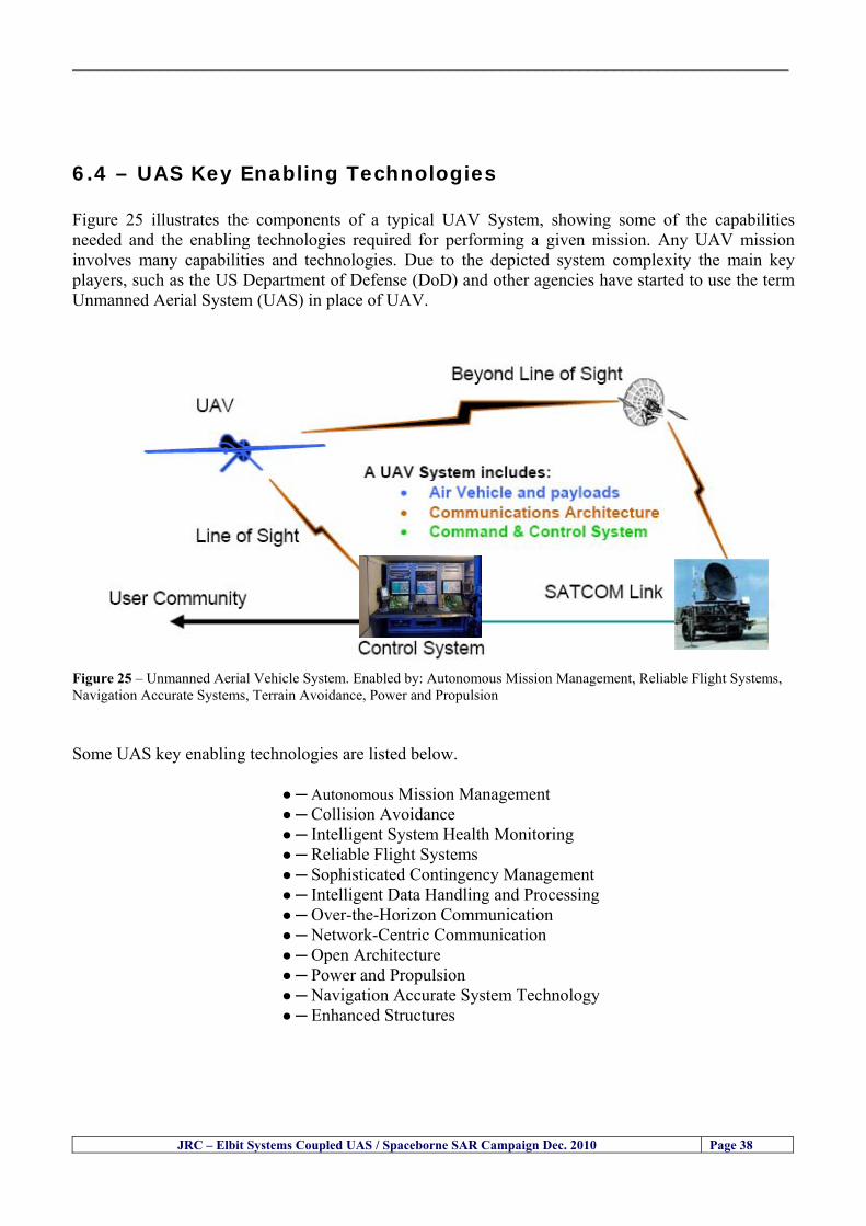
__________________________________________________________________________________
64 ndash UAS Key Enabling Technologies Figure 25 illustrates the components of a typical UAV System showing some of the capabilities needed and the enabling technologies required for performing a given mission Any UAV mission involves many capabilities and technologies Due to the depicted system complexity the main key players such as the US Department of Defense (DoD) and other agencies have started to use the term Unmanned Aerial System (UAS) in place of UAV
Figure 25 ndash Unmanned Aerial Vehicle System Enabled by Autonomous Mission Management Reliable Flight Systems Navigation Accurate Systems Terrain Avoidance Power and Propulsion Some UAS key enabling technologies are listed below
Autonomous Mission Management Collision Avoidance Intelligent System Health Monitoring
Reliable Flight Systems Sophisticated Contingency Management Intelligent Data Handling and Processing Over-the-Horizon Communication Network-Centric Communication Open Architecture Power and Propulsion Navigation Accurate System Technology Enhanced Structures
JRC ndash Elbit Systems Coupled UAS Spaceborne SAR Campaign Dec 2010 Page 38
__________________________________________________________________________________
JRC ndash Elbit Systems Coupled UAS Spaceborne SAR Campaign Dec 2010 Page 39
Table 12 gives a more detailed description of other critical technologies for emerging autonomous UAV systems both civil and military Most of the technologies mentioned in Table 12 apply both to civil and military UAV systems Table 10 ndash Key Enabling Technologies (from SG75 study on autonomous systems)
Critical Technologies Decision Making Software
bull Fuzzy-based decision making bull Knowledge-based system bull Case-based reasoning bull Self-learning techniques bull Decision tree evaluation bull ReasoningInferring bull Probabilisticstochastic reasoning
Prediction Algorithms bull Predictive pathintent algorithms bull Short reaction algorithm bull Effectiveness evaluation
Status Assessment Software bull Internal status analysis bull Self-orientation
Situation Analysis Software bull Situation analysis bull Environmental analysis bull External status analysis
Modelling Software bull Air vehicle modelling algorithms bull Sensor modelling algorithms bull Scenario generation bull Threat system modeling bull Attack simulation bull Mission success optimisation model bull Simulation
Sensor Processing Software bull Sensor fusion bull Area of interest identification bull Automatic target recognition
Adaptive and Self-learning Systems bull Failure self-compensation
Attack Planning Software bull Attack plans and tactical alternatives bull Plan change impact identification
Weapon Engagement Procedure Software bull Weapon engagement algorithms
Mission Plan Update Software bull Route planning system bull Payload plan management system bull Mission Success Optimisation model
Path Optimisation Software bull Optimal trajectory planning bull Path Optimisation System
Targeting Software bull Target tracking bull Target prioritisation
Platform Technologies bull Obstacle detection and avoidance (airborne) bull Obstacle detection and avoidance (ground) bull Improved autopilot bull Speech recognition
Figure 26 summarises system element designs needed to transition from current to next-generation autonomous UAV systems for civilian and military UAS
__________________________________________________________________________________
Figure 26 ndash System Element Designs Needed to Transition from Current to Next-Generation Autonomous UAV Systems These new paradigms are a combination of system attributes and technological capabilities For instance the data fusion secure anti-jam and coordinated multi-vehicle control require technological development as well as specific system development to bring full maturity to unmanned systems Finally very small Micro UAVs (MAVs) and relatively large sophisticated UCAV systems are examples of the range of UAVs that are applying the new platforms payloads onboard processing communications etc to create next generation automated UAVs It is with these new platforms payloads etc that both UCAVs and MAV will be able to address similar operational challenges including
Mixed operation with other assets bull Deconfliction collision avoidance C4I integration
Operation over populated areas bull Safety issues Need to reduce reliance on communications bull UCAV ndash countermeasures bull MAV ndash limited size and power bull Limited line of sight environment Need a fully integrated system bull MAV propulsionpower generation still critical bull Operator machine interface critical bull All weather operations bull Survivability
JRC ndash Elbit Systems Coupled UAS Spaceborne SAR Campaign Dec 2010 Page 40
__________________________________________________________________________________
JRC ndash Elbit Systems Coupled UAS Spaceborne SAR Campaign Dec 2010 Page 41
65 ndash Mission Readiness
651 ndash Mission Readiness Summary This section summarises civil UAV mission readiness The purpose of Mission Readiness is to assess the readiness status of the different technologies involved in UAS In the present case this civil UAV mission readiness based on technology maturation forecasts that meet or exceed the desired or required capabilities identified by the user community Figure 27 summarises the mission readiness time forecasts for the different technologies The technologies annotated with an asterisk () are shown within the figure with maturation forecasts based on development targets expressed in the US Department of Defencesrsquo UAV Roadmap document The purpose of the chart is to be able to identify when the capability to fly a particular mission can be expected as a function of time The left-most end is the least probable and the right end the most probable timeframe
Figure 27 ndash Technology Maturation Summaries in Terms of Mission-Derived Capabilities
__________________________________________________________________________________
JRC ndash Elbit Systems Coupled UAS Spaceborne SAR Campaign Dec 2010 Page 42
66 ndash Small Boat Detection in SAR Satellite Imagery The use of spaceborne SAR imagery for small boat detection requires additional small boat detection experiments under different conditions using different methods It is not possible to draw final conclusions based on a limited number of small boat detection experiments which are not representative of the multiple possible scenarios
67 ndash Limitations of current State-of-the-Art SAR Satellite technology The main limitations of current State-of-the-Art spaceborne SAR imagery for maritime surveillance in particular aimed at small boat detection are 1 - SAR satellites repeat cycles do not allow the coverage of the same area at the required time intervals Constellations of SAR satellites could be a solution 2 - The conflict between resolution and image swath High resolution is required to detect small boats However the high resolution images have small swaths Maritime surveillance with high resolution images would require a large number of images to cover wide maritime areas which is very expensive and for the time being technically not feasible Intelligence data can play an important role by indicating an approximate position of suspicious non cooperative targets therefore reducing the surveillance area which can then be imaged using high resolution images 3- Spaceborne high resolution SAR imagery acquisition times are long enough to allow significant motion of the target during the acquisition time degrading the quality of the image Further research efforts are needed to develop new sensors and platforms As far as sensors are concerned shorter integration times are needed to prevent the blurring effect caused by the motion of the targets Regarding the platforms more platforms are needed to allow lower repeat cycles and improved coverage
__________________________________________________________________________________
JRC ndash Elbit Systems Coupled UAS Spaceborne SAR Campaign Dec 2010 Page 43
7 ndash Plans for Future Work The controlled experiments carried out by the EC-JRC together with Elbit Systems in Haifa-Israel comprised the deployment of a UAS (Hermes-450) and one small 12-meter boat A Radarsat-2 Spotlight image was acquired and several images collected by the Hermes-450 The experiment unveiled the potential of UAS for maritime surveillance in particular for detection tracking classification and possible identification of small targets The UAS was able to detect track and classify small targets such as small boats For low UAS altitude flights identification may be possible in some cases The small 12-meter boat was detected in the spaceborne SAR image The small boat detection trials carried out by the JRC were very successful since most small boats deployed during the experiments were detected in different sea states wind speeds and geographical locations The several small boat detection campaigns conducted by the EC-JRC seem to suggest that the probability of detection of small boats in spaceborne SAR images strongly depends on factors such as the sea state the wind speed the type of boat (shape and materials) the weather conditions among other factors The results of the experiments conducted thus far are not enough to draw final conclusions about the feasibility of using spaceborne SAR imagery for small boat detection However the experiments have an overall positive outcome because they indicate that under suitable sea state and wind speed conditions it is possible to detect small boats using spaceborne SAR The estimation of the probability of detection of small boats in spaceborne SAR images requires a large number of experiments under different circumstances (eg sea state wind speed characteristics of the targets image type and mode etc) Future plans include additional UAS experiments to asses its potential for maritime surveillance
Acknowledgements ndash The authors would like to express their gratitude to Elbit Systems for their cooperation logistical support and assets deployed without which the present coupled UASSAR Satellite Small Boat Detection Campaign would have not been possible
__________________________________________________________________________________
JRC ndash Elbit Systems Coupled UAS Spaceborne SAR Campaign Dec 2010 Page 44
REFERENCES [1] Elbit Systems ldquoUAV Elbit Systems Proposal for Unmanned Aerial Vehicle (UAV) flight to
collect Ground Truth data during a Maritime Surveillance Campaign and demonstrate UAV capabilities for Maritime Surveillancerdquo 2010
[2] ndash Cheryl Yuhas Suborbital Science Program Manager NASA Science Mission Directorate ldquoEarth Observations and the Role of UAVs A Capabilities Assessment Version 11rdquo Civil UAV Assessment Team httpwwwnasagovcentersdrydenresearchcivuavindexhtml August 2006
[3] ndash Document NIAG (SG75) NATO Industrial Advisory Group Study Group 75 Pre-Feasibility Study on UAV Autonomous Operations 2004
[4] ndash United States Department of Defence (DoD) Directive 50001 ldquoThe Defense Acquisition Systemrdquo and DoD Instruction 50002 ldquoOperation of the Defense Acquisition Systemrdquo
[5] ndash Mr James Ramage Mr Massimo Avalle Dr Erik Berglund Dr Luigi Crovella Mr Robert Frampton Dr Uwe Krogmann Mr Christian Ravat Mr Mike Robinson Dr Axel Schulte Dr Scott Wood ldquoRTO-TR-SCI-118 - Automation Technologies and Application Considerations for Highly Integrated Mission Systemsrdquo RTO-TR-SCI-118 AC323(SCI-118)TP204 January 2009
[6] Victor MG Silva Gilles Jurquet Gabriel Marchalot Maria TG Calzado Txema Soroa Juan Sancho Adam Koubek Harm Greidanus and Claudio Savarino ldquoWide Maritime Area Airborne Surveillance (WIMA2S) WP5 Final Reportrdquo WIMAAS WP5 FP7 Project 2008-2011 - ISBN-978-92-79-22801-8 (print) 978-92-79-22802-5 (PDF) ISSN-1018-5593 (print) 1831-9424 (online) EC-JRC Scientific Report JRC 70093 2012
[7] Victor MG Silva and Harm Greidanus ldquoSpaceborne SAR Small Boat Detection Campaign in Portugal and Spainrdquo EUR 25281 EN ISBN 978-92-79-22553-6 ISSN 1831-9424 (online) EC-JRC Scientific Report JRC68160 2012
[8] Goncalves Da Silva V Van Wimersma Greidanus H Hejmanowska B Loudjani P ldquoUAS Applications With Societal Benefits ndash JRCrsquos UAS-Related Activitiesrdquo 2011-2012 UAS Yearbook - UAS Unmanned Aircraft Systems - The Global Perspective 9 (9) 2011 p 127-129 JRC66600
[9] Goncalves Da Silva V Van Wimersma Greidanus H ldquoSmall boat detection using TerraSAR-X and Radarsat2 satellite imageryrdquo 4th TerraSAR-X Science Team Meeting 14 February 2011 DLR Oberpfaffenhofen (Germany) German Aerospace Center (DLR) (Organiser) 2011 JRC63663
[10] V Silva Harm Greidanus ldquoJRC - SAR Satellite Small Boat Detection Campaign - Portoroz ndash Sloveniardquo - ISBN-13 978-92-79-21476-9 ISSN (online) 1831-9424 EC-JRC Scientific Report JRC66835 2011
[11] V Silva Harm Greidanus ldquoJRC - SAR satellite small boat detection campaign - Algarve Portugalrdquo - ISBN-13 978-92-79-21265-9 ISSN (online) 1831-9424 ISSN (print) 1018-5593 EC-JRC Scientific Report JRC66631 2011
[12] ndash Goncalves Da Silva V Van Wimersma Greidanus H ldquoJRC-Frontex Spaceborne SAR Small Boat Detection Campaign ndash Italy amp Spainrdquo - ISBN-13 978-92-79-22213-9 ISSN (online) 1831-9424 EC-JRC Scientific Report JRC67517 2011
[13] - PW Vachon SJ Thomas J Cranton HR Edel and MD Henschel Validation of ship detection by the RADARSAT synthetic aperture radar and the Ocean Monitoring Workstation Canadian Journal of Remote Sensing 26(3)200ndash212 2000
[14] - Crisp D (2004) The state-of-the-art in ship detection in Synthetic Aperture Radar imagery DSTO Information Sciences Laboratory Australia
[15] - Joint Research Centre (JRC) of the European Community mdash IMPAST and DECLIMS web site httpintelligencejrcceceuintmarinefishindexhtm
[16] - McCandless SW Jackson CR (2004) Principles of Synthetic Aperture Radar Synthetic Aperture Radar Marine Users Manual NOAA Washington pp 1-23
[17] - Greidanus H (2008) Satellite Imaging for Maritime Surveillance of the European Seas Remote Sensing of the European Seas 343-358
European Commission
EUR 25346 EN --- Joint Research Centre --- Institute for the Protection and Security of the Citizen
Title JRC --- Elbit Systems Coupled UAS and Spaceborne SAR Campaign in Israel
Authors Victor MG Silva Harm Greidanus
Luxembourg Publications Office of the European Union
2012 --- v+44 pp --- 210 x 297 cm
EUR --- Scientific and Technical Research series --- ISSN 181-9424 (online) ISSN 1018-5593 (print)
ISBN 978-92-79-25020-0
doi10278828527
Abstract The European maritime area is one of Europersquos most important assets with regard to resources security and ultimately
prosperity of the Member States A significant part of Europersquos economy relies directly or indirectly on it It is not just the
shipping or fisheries industries and their related activities It is also shipbuilding and ports marine equipment and offshore
energy maritime and coastal tourism aquaculture submarine telecommunications blue biotech and the protection of the
marine environment The European maritime area faces several risks and threats posed by unlawful activities such as drugs
trafficking smuggling illegal immigration organised crime and terrorism Piracy in international waters also constitutes a threat
to Europe since it can disrupt the maritime transport chain These risks and threats can endanger human lives marine resources
and the environment as well as significantly disrupt the transport chain and global and local security It is anticipated that these
risks and threats will endure in the mid and long run In order to keep Europe as a world leader in the global maritime economy
an effective integratedinteroperable sustainable maritime surveillance system and situational awareness are needed
A significant number of unlawful maritime activities such as illegal immigration drugs trafficking smuggling piracy and
terrorism involve mainly small boats because small boats are faster and more difficult to detect using conventional means
Hence it is very important to find out the feasibility of using Unmanned Aerial Systems (UAS) for small boat detection tracking
classification and identification as well as to study the potential of UAS for maritime surveillance Since 2010 the EC-JRC has
carried out a number of UAS maritime surveillance campaigns to study the potential of UAS for maritime surveillance in
particular for small boat detection This report presents the results and conclusions of the JRC --- Elbit Systems Coupled UAS and
Spaceborne SAR campaign carried out in Dec 2010 in Haifa Israel
As the Commissionrsquos in-house science service the Joint Research Centrersquos mission is to provide EU policies with independent evidence-based scientific and technical support throughout the whole policy cycle Working in close cooperation with policy Directorates-General the JRC addresses key societal challenges while stimulating innovation through developing new standards methods and tools and sharing and transferring its know-how to the Member States and international community Key policy areas include environment and climate change energy and transport agriculture and food security health and consumer protection information society and digital agenda safety and security including nuclear all supported through a cross-cutting and multi-disciplinary approach
LB-NA-25346-EN
-N
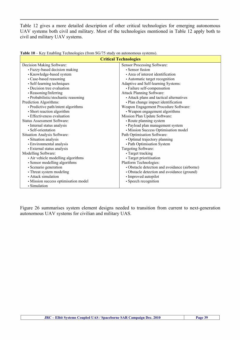
__________________________________________________________________________________
JRC ndash Elbit Systems Coupled UAS Spaceborne SAR Campaign Dec 2010 Page 39
Table 12 gives a more detailed description of other critical technologies for emerging autonomous UAV systems both civil and military Most of the technologies mentioned in Table 12 apply both to civil and military UAV systems Table 10 ndash Key Enabling Technologies (from SG75 study on autonomous systems)
Critical Technologies Decision Making Software
bull Fuzzy-based decision making bull Knowledge-based system bull Case-based reasoning bull Self-learning techniques bull Decision tree evaluation bull ReasoningInferring bull Probabilisticstochastic reasoning
Prediction Algorithms bull Predictive pathintent algorithms bull Short reaction algorithm bull Effectiveness evaluation
Status Assessment Software bull Internal status analysis bull Self-orientation
Situation Analysis Software bull Situation analysis bull Environmental analysis bull External status analysis
Modelling Software bull Air vehicle modelling algorithms bull Sensor modelling algorithms bull Scenario generation bull Threat system modeling bull Attack simulation bull Mission success optimisation model bull Simulation
Sensor Processing Software bull Sensor fusion bull Area of interest identification bull Automatic target recognition
Adaptive and Self-learning Systems bull Failure self-compensation
Attack Planning Software bull Attack plans and tactical alternatives bull Plan change impact identification
Weapon Engagement Procedure Software bull Weapon engagement algorithms
Mission Plan Update Software bull Route planning system bull Payload plan management system bull Mission Success Optimisation model
Path Optimisation Software bull Optimal trajectory planning bull Path Optimisation System
Targeting Software bull Target tracking bull Target prioritisation
Platform Technologies bull Obstacle detection and avoidance (airborne) bull Obstacle detection and avoidance (ground) bull Improved autopilot bull Speech recognition
Figure 26 summarises system element designs needed to transition from current to next-generation autonomous UAV systems for civilian and military UAS
__________________________________________________________________________________
Figure 26 ndash System Element Designs Needed to Transition from Current to Next-Generation Autonomous UAV Systems These new paradigms are a combination of system attributes and technological capabilities For instance the data fusion secure anti-jam and coordinated multi-vehicle control require technological development as well as specific system development to bring full maturity to unmanned systems Finally very small Micro UAVs (MAVs) and relatively large sophisticated UCAV systems are examples of the range of UAVs that are applying the new platforms payloads onboard processing communications etc to create next generation automated UAVs It is with these new platforms payloads etc that both UCAVs and MAV will be able to address similar operational challenges including
Mixed operation with other assets bull Deconfliction collision avoidance C4I integration
Operation over populated areas bull Safety issues Need to reduce reliance on communications bull UCAV ndash countermeasures bull MAV ndash limited size and power bull Limited line of sight environment Need a fully integrated system bull MAV propulsionpower generation still critical bull Operator machine interface critical bull All weather operations bull Survivability
JRC ndash Elbit Systems Coupled UAS Spaceborne SAR Campaign Dec 2010 Page 40
__________________________________________________________________________________
JRC ndash Elbit Systems Coupled UAS Spaceborne SAR Campaign Dec 2010 Page 41
65 ndash Mission Readiness
651 ndash Mission Readiness Summary This section summarises civil UAV mission readiness The purpose of Mission Readiness is to assess the readiness status of the different technologies involved in UAS In the present case this civil UAV mission readiness based on technology maturation forecasts that meet or exceed the desired or required capabilities identified by the user community Figure 27 summarises the mission readiness time forecasts for the different technologies The technologies annotated with an asterisk () are shown within the figure with maturation forecasts based on development targets expressed in the US Department of Defencesrsquo UAV Roadmap document The purpose of the chart is to be able to identify when the capability to fly a particular mission can be expected as a function of time The left-most end is the least probable and the right end the most probable timeframe
Figure 27 ndash Technology Maturation Summaries in Terms of Mission-Derived Capabilities
__________________________________________________________________________________
JRC ndash Elbit Systems Coupled UAS Spaceborne SAR Campaign Dec 2010 Page 42
66 ndash Small Boat Detection in SAR Satellite Imagery The use of spaceborne SAR imagery for small boat detection requires additional small boat detection experiments under different conditions using different methods It is not possible to draw final conclusions based on a limited number of small boat detection experiments which are not representative of the multiple possible scenarios
67 ndash Limitations of current State-of-the-Art SAR Satellite technology The main limitations of current State-of-the-Art spaceborne SAR imagery for maritime surveillance in particular aimed at small boat detection are 1 - SAR satellites repeat cycles do not allow the coverage of the same area at the required time intervals Constellations of SAR satellites could be a solution 2 - The conflict between resolution and image swath High resolution is required to detect small boats However the high resolution images have small swaths Maritime surveillance with high resolution images would require a large number of images to cover wide maritime areas which is very expensive and for the time being technically not feasible Intelligence data can play an important role by indicating an approximate position of suspicious non cooperative targets therefore reducing the surveillance area which can then be imaged using high resolution images 3- Spaceborne high resolution SAR imagery acquisition times are long enough to allow significant motion of the target during the acquisition time degrading the quality of the image Further research efforts are needed to develop new sensors and platforms As far as sensors are concerned shorter integration times are needed to prevent the blurring effect caused by the motion of the targets Regarding the platforms more platforms are needed to allow lower repeat cycles and improved coverage
__________________________________________________________________________________
JRC ndash Elbit Systems Coupled UAS Spaceborne SAR Campaign Dec 2010 Page 43
7 ndash Plans for Future Work The controlled experiments carried out by the EC-JRC together with Elbit Systems in Haifa-Israel comprised the deployment of a UAS (Hermes-450) and one small 12-meter boat A Radarsat-2 Spotlight image was acquired and several images collected by the Hermes-450 The experiment unveiled the potential of UAS for maritime surveillance in particular for detection tracking classification and possible identification of small targets The UAS was able to detect track and classify small targets such as small boats For low UAS altitude flights identification may be possible in some cases The small 12-meter boat was detected in the spaceborne SAR image The small boat detection trials carried out by the JRC were very successful since most small boats deployed during the experiments were detected in different sea states wind speeds and geographical locations The several small boat detection campaigns conducted by the EC-JRC seem to suggest that the probability of detection of small boats in spaceborne SAR images strongly depends on factors such as the sea state the wind speed the type of boat (shape and materials) the weather conditions among other factors The results of the experiments conducted thus far are not enough to draw final conclusions about the feasibility of using spaceborne SAR imagery for small boat detection However the experiments have an overall positive outcome because they indicate that under suitable sea state and wind speed conditions it is possible to detect small boats using spaceborne SAR The estimation of the probability of detection of small boats in spaceborne SAR images requires a large number of experiments under different circumstances (eg sea state wind speed characteristics of the targets image type and mode etc) Future plans include additional UAS experiments to asses its potential for maritime surveillance
Acknowledgements ndash The authors would like to express their gratitude to Elbit Systems for their cooperation logistical support and assets deployed without which the present coupled UASSAR Satellite Small Boat Detection Campaign would have not been possible
__________________________________________________________________________________
JRC ndash Elbit Systems Coupled UAS Spaceborne SAR Campaign Dec 2010 Page 44
REFERENCES [1] Elbit Systems ldquoUAV Elbit Systems Proposal for Unmanned Aerial Vehicle (UAV) flight to
collect Ground Truth data during a Maritime Surveillance Campaign and demonstrate UAV capabilities for Maritime Surveillancerdquo 2010
[2] ndash Cheryl Yuhas Suborbital Science Program Manager NASA Science Mission Directorate ldquoEarth Observations and the Role of UAVs A Capabilities Assessment Version 11rdquo Civil UAV Assessment Team httpwwwnasagovcentersdrydenresearchcivuavindexhtml August 2006
[3] ndash Document NIAG (SG75) NATO Industrial Advisory Group Study Group 75 Pre-Feasibility Study on UAV Autonomous Operations 2004
[4] ndash United States Department of Defence (DoD) Directive 50001 ldquoThe Defense Acquisition Systemrdquo and DoD Instruction 50002 ldquoOperation of the Defense Acquisition Systemrdquo
[5] ndash Mr James Ramage Mr Massimo Avalle Dr Erik Berglund Dr Luigi Crovella Mr Robert Frampton Dr Uwe Krogmann Mr Christian Ravat Mr Mike Robinson Dr Axel Schulte Dr Scott Wood ldquoRTO-TR-SCI-118 - Automation Technologies and Application Considerations for Highly Integrated Mission Systemsrdquo RTO-TR-SCI-118 AC323(SCI-118)TP204 January 2009
[6] Victor MG Silva Gilles Jurquet Gabriel Marchalot Maria TG Calzado Txema Soroa Juan Sancho Adam Koubek Harm Greidanus and Claudio Savarino ldquoWide Maritime Area Airborne Surveillance (WIMA2S) WP5 Final Reportrdquo WIMAAS WP5 FP7 Project 2008-2011 - ISBN-978-92-79-22801-8 (print) 978-92-79-22802-5 (PDF) ISSN-1018-5593 (print) 1831-9424 (online) EC-JRC Scientific Report JRC 70093 2012
[7] Victor MG Silva and Harm Greidanus ldquoSpaceborne SAR Small Boat Detection Campaign in Portugal and Spainrdquo EUR 25281 EN ISBN 978-92-79-22553-6 ISSN 1831-9424 (online) EC-JRC Scientific Report JRC68160 2012
[8] Goncalves Da Silva V Van Wimersma Greidanus H Hejmanowska B Loudjani P ldquoUAS Applications With Societal Benefits ndash JRCrsquos UAS-Related Activitiesrdquo 2011-2012 UAS Yearbook - UAS Unmanned Aircraft Systems - The Global Perspective 9 (9) 2011 p 127-129 JRC66600
[9] Goncalves Da Silva V Van Wimersma Greidanus H ldquoSmall boat detection using TerraSAR-X and Radarsat2 satellite imageryrdquo 4th TerraSAR-X Science Team Meeting 14 February 2011 DLR Oberpfaffenhofen (Germany) German Aerospace Center (DLR) (Organiser) 2011 JRC63663
[10] V Silva Harm Greidanus ldquoJRC - SAR Satellite Small Boat Detection Campaign - Portoroz ndash Sloveniardquo - ISBN-13 978-92-79-21476-9 ISSN (online) 1831-9424 EC-JRC Scientific Report JRC66835 2011
[11] V Silva Harm Greidanus ldquoJRC - SAR satellite small boat detection campaign - Algarve Portugalrdquo - ISBN-13 978-92-79-21265-9 ISSN (online) 1831-9424 ISSN (print) 1018-5593 EC-JRC Scientific Report JRC66631 2011
[12] ndash Goncalves Da Silva V Van Wimersma Greidanus H ldquoJRC-Frontex Spaceborne SAR Small Boat Detection Campaign ndash Italy amp Spainrdquo - ISBN-13 978-92-79-22213-9 ISSN (online) 1831-9424 EC-JRC Scientific Report JRC67517 2011
[13] - PW Vachon SJ Thomas J Cranton HR Edel and MD Henschel Validation of ship detection by the RADARSAT synthetic aperture radar and the Ocean Monitoring Workstation Canadian Journal of Remote Sensing 26(3)200ndash212 2000
[14] - Crisp D (2004) The state-of-the-art in ship detection in Synthetic Aperture Radar imagery DSTO Information Sciences Laboratory Australia
[15] - Joint Research Centre (JRC) of the European Community mdash IMPAST and DECLIMS web site httpintelligencejrcceceuintmarinefishindexhtm
[16] - McCandless SW Jackson CR (2004) Principles of Synthetic Aperture Radar Synthetic Aperture Radar Marine Users Manual NOAA Washington pp 1-23
[17] - Greidanus H (2008) Satellite Imaging for Maritime Surveillance of the European Seas Remote Sensing of the European Seas 343-358
European Commission
EUR 25346 EN --- Joint Research Centre --- Institute for the Protection and Security of the Citizen
Title JRC --- Elbit Systems Coupled UAS and Spaceborne SAR Campaign in Israel
Authors Victor MG Silva Harm Greidanus
Luxembourg Publications Office of the European Union
2012 --- v+44 pp --- 210 x 297 cm
EUR --- Scientific and Technical Research series --- ISSN 181-9424 (online) ISSN 1018-5593 (print)
ISBN 978-92-79-25020-0
doi10278828527
Abstract The European maritime area is one of Europersquos most important assets with regard to resources security and ultimately
prosperity of the Member States A significant part of Europersquos economy relies directly or indirectly on it It is not just the
shipping or fisheries industries and their related activities It is also shipbuilding and ports marine equipment and offshore
energy maritime and coastal tourism aquaculture submarine telecommunications blue biotech and the protection of the
marine environment The European maritime area faces several risks and threats posed by unlawful activities such as drugs
trafficking smuggling illegal immigration organised crime and terrorism Piracy in international waters also constitutes a threat
to Europe since it can disrupt the maritime transport chain These risks and threats can endanger human lives marine resources
and the environment as well as significantly disrupt the transport chain and global and local security It is anticipated that these
risks and threats will endure in the mid and long run In order to keep Europe as a world leader in the global maritime economy
an effective integratedinteroperable sustainable maritime surveillance system and situational awareness are needed
A significant number of unlawful maritime activities such as illegal immigration drugs trafficking smuggling piracy and
terrorism involve mainly small boats because small boats are faster and more difficult to detect using conventional means
Hence it is very important to find out the feasibility of using Unmanned Aerial Systems (UAS) for small boat detection tracking
classification and identification as well as to study the potential of UAS for maritime surveillance Since 2010 the EC-JRC has
carried out a number of UAS maritime surveillance campaigns to study the potential of UAS for maritime surveillance in
particular for small boat detection This report presents the results and conclusions of the JRC --- Elbit Systems Coupled UAS and
Spaceborne SAR campaign carried out in Dec 2010 in Haifa Israel
As the Commissionrsquos in-house science service the Joint Research Centrersquos mission is to provide EU policies with independent evidence-based scientific and technical support throughout the whole policy cycle Working in close cooperation with policy Directorates-General the JRC addresses key societal challenges while stimulating innovation through developing new standards methods and tools and sharing and transferring its know-how to the Member States and international community Key policy areas include environment and climate change energy and transport agriculture and food security health and consumer protection information society and digital agenda safety and security including nuclear all supported through a cross-cutting and multi-disciplinary approach
LB-NA-25346-EN
-N
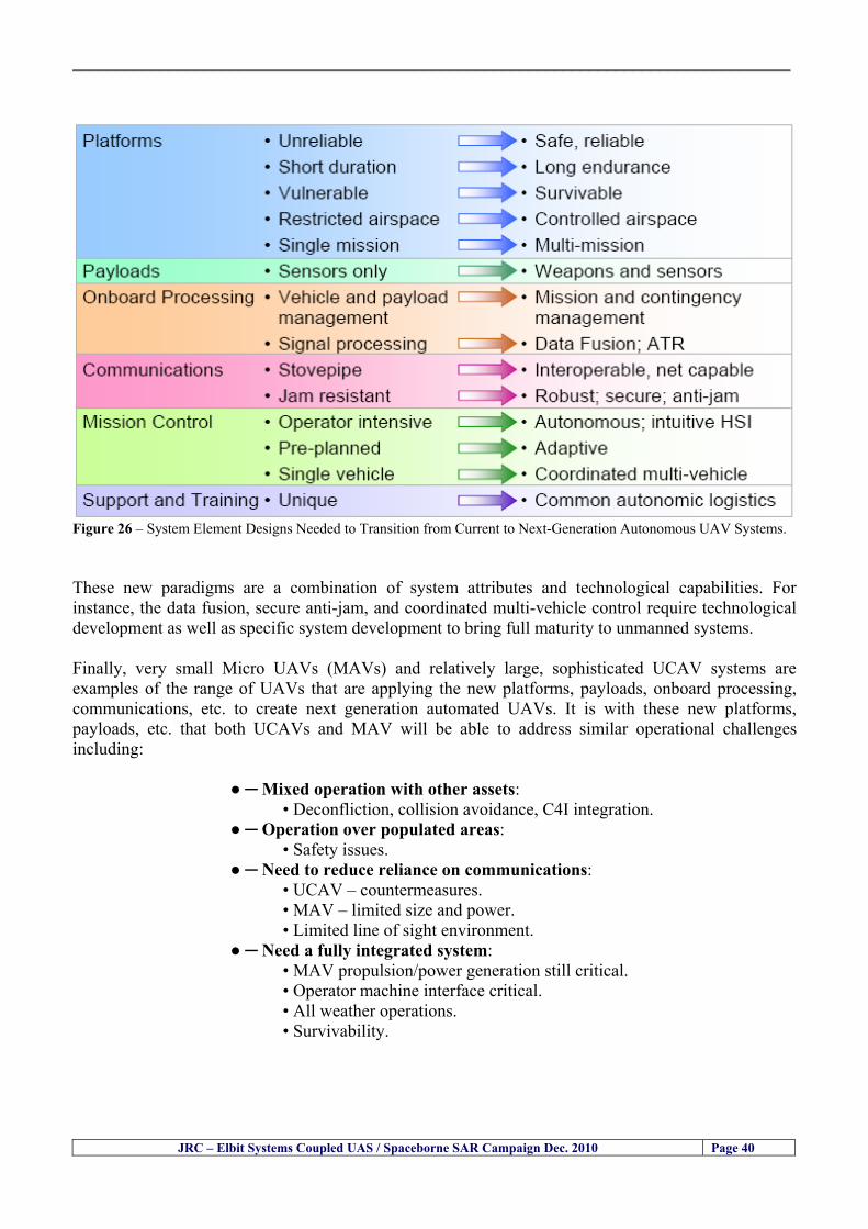
__________________________________________________________________________________
Figure 26 ndash System Element Designs Needed to Transition from Current to Next-Generation Autonomous UAV Systems These new paradigms are a combination of system attributes and technological capabilities For instance the data fusion secure anti-jam and coordinated multi-vehicle control require technological development as well as specific system development to bring full maturity to unmanned systems Finally very small Micro UAVs (MAVs) and relatively large sophisticated UCAV systems are examples of the range of UAVs that are applying the new platforms payloads onboard processing communications etc to create next generation automated UAVs It is with these new platforms payloads etc that both UCAVs and MAV will be able to address similar operational challenges including
Mixed operation with other assets bull Deconfliction collision avoidance C4I integration
Operation over populated areas bull Safety issues Need to reduce reliance on communications bull UCAV ndash countermeasures bull MAV ndash limited size and power bull Limited line of sight environment Need a fully integrated system bull MAV propulsionpower generation still critical bull Operator machine interface critical bull All weather operations bull Survivability
JRC ndash Elbit Systems Coupled UAS Spaceborne SAR Campaign Dec 2010 Page 40
__________________________________________________________________________________
JRC ndash Elbit Systems Coupled UAS Spaceborne SAR Campaign Dec 2010 Page 41
65 ndash Mission Readiness
651 ndash Mission Readiness Summary This section summarises civil UAV mission readiness The purpose of Mission Readiness is to assess the readiness status of the different technologies involved in UAS In the present case this civil UAV mission readiness based on technology maturation forecasts that meet or exceed the desired or required capabilities identified by the user community Figure 27 summarises the mission readiness time forecasts for the different technologies The technologies annotated with an asterisk () are shown within the figure with maturation forecasts based on development targets expressed in the US Department of Defencesrsquo UAV Roadmap document The purpose of the chart is to be able to identify when the capability to fly a particular mission can be expected as a function of time The left-most end is the least probable and the right end the most probable timeframe
Figure 27 ndash Technology Maturation Summaries in Terms of Mission-Derived Capabilities
__________________________________________________________________________________
JRC ndash Elbit Systems Coupled UAS Spaceborne SAR Campaign Dec 2010 Page 42
66 ndash Small Boat Detection in SAR Satellite Imagery The use of spaceborne SAR imagery for small boat detection requires additional small boat detection experiments under different conditions using different methods It is not possible to draw final conclusions based on a limited number of small boat detection experiments which are not representative of the multiple possible scenarios
67 ndash Limitations of current State-of-the-Art SAR Satellite technology The main limitations of current State-of-the-Art spaceborne SAR imagery for maritime surveillance in particular aimed at small boat detection are 1 - SAR satellites repeat cycles do not allow the coverage of the same area at the required time intervals Constellations of SAR satellites could be a solution 2 - The conflict between resolution and image swath High resolution is required to detect small boats However the high resolution images have small swaths Maritime surveillance with high resolution images would require a large number of images to cover wide maritime areas which is very expensive and for the time being technically not feasible Intelligence data can play an important role by indicating an approximate position of suspicious non cooperative targets therefore reducing the surveillance area which can then be imaged using high resolution images 3- Spaceborne high resolution SAR imagery acquisition times are long enough to allow significant motion of the target during the acquisition time degrading the quality of the image Further research efforts are needed to develop new sensors and platforms As far as sensors are concerned shorter integration times are needed to prevent the blurring effect caused by the motion of the targets Regarding the platforms more platforms are needed to allow lower repeat cycles and improved coverage
__________________________________________________________________________________
JRC ndash Elbit Systems Coupled UAS Spaceborne SAR Campaign Dec 2010 Page 43
7 ndash Plans for Future Work The controlled experiments carried out by the EC-JRC together with Elbit Systems in Haifa-Israel comprised the deployment of a UAS (Hermes-450) and one small 12-meter boat A Radarsat-2 Spotlight image was acquired and several images collected by the Hermes-450 The experiment unveiled the potential of UAS for maritime surveillance in particular for detection tracking classification and possible identification of small targets The UAS was able to detect track and classify small targets such as small boats For low UAS altitude flights identification may be possible in some cases The small 12-meter boat was detected in the spaceborne SAR image The small boat detection trials carried out by the JRC were very successful since most small boats deployed during the experiments were detected in different sea states wind speeds and geographical locations The several small boat detection campaigns conducted by the EC-JRC seem to suggest that the probability of detection of small boats in spaceborne SAR images strongly depends on factors such as the sea state the wind speed the type of boat (shape and materials) the weather conditions among other factors The results of the experiments conducted thus far are not enough to draw final conclusions about the feasibility of using spaceborne SAR imagery for small boat detection However the experiments have an overall positive outcome because they indicate that under suitable sea state and wind speed conditions it is possible to detect small boats using spaceborne SAR The estimation of the probability of detection of small boats in spaceborne SAR images requires a large number of experiments under different circumstances (eg sea state wind speed characteristics of the targets image type and mode etc) Future plans include additional UAS experiments to asses its potential for maritime surveillance
Acknowledgements ndash The authors would like to express their gratitude to Elbit Systems for their cooperation logistical support and assets deployed without which the present coupled UASSAR Satellite Small Boat Detection Campaign would have not been possible
__________________________________________________________________________________
JRC ndash Elbit Systems Coupled UAS Spaceborne SAR Campaign Dec 2010 Page 44
REFERENCES [1] Elbit Systems ldquoUAV Elbit Systems Proposal for Unmanned Aerial Vehicle (UAV) flight to
collect Ground Truth data during a Maritime Surveillance Campaign and demonstrate UAV capabilities for Maritime Surveillancerdquo 2010
[2] ndash Cheryl Yuhas Suborbital Science Program Manager NASA Science Mission Directorate ldquoEarth Observations and the Role of UAVs A Capabilities Assessment Version 11rdquo Civil UAV Assessment Team httpwwwnasagovcentersdrydenresearchcivuavindexhtml August 2006
[3] ndash Document NIAG (SG75) NATO Industrial Advisory Group Study Group 75 Pre-Feasibility Study on UAV Autonomous Operations 2004
[4] ndash United States Department of Defence (DoD) Directive 50001 ldquoThe Defense Acquisition Systemrdquo and DoD Instruction 50002 ldquoOperation of the Defense Acquisition Systemrdquo
[5] ndash Mr James Ramage Mr Massimo Avalle Dr Erik Berglund Dr Luigi Crovella Mr Robert Frampton Dr Uwe Krogmann Mr Christian Ravat Mr Mike Robinson Dr Axel Schulte Dr Scott Wood ldquoRTO-TR-SCI-118 - Automation Technologies and Application Considerations for Highly Integrated Mission Systemsrdquo RTO-TR-SCI-118 AC323(SCI-118)TP204 January 2009
[6] Victor MG Silva Gilles Jurquet Gabriel Marchalot Maria TG Calzado Txema Soroa Juan Sancho Adam Koubek Harm Greidanus and Claudio Savarino ldquoWide Maritime Area Airborne Surveillance (WIMA2S) WP5 Final Reportrdquo WIMAAS WP5 FP7 Project 2008-2011 - ISBN-978-92-79-22801-8 (print) 978-92-79-22802-5 (PDF) ISSN-1018-5593 (print) 1831-9424 (online) EC-JRC Scientific Report JRC 70093 2012
[7] Victor MG Silva and Harm Greidanus ldquoSpaceborne SAR Small Boat Detection Campaign in Portugal and Spainrdquo EUR 25281 EN ISBN 978-92-79-22553-6 ISSN 1831-9424 (online) EC-JRC Scientific Report JRC68160 2012
[8] Goncalves Da Silva V Van Wimersma Greidanus H Hejmanowska B Loudjani P ldquoUAS Applications With Societal Benefits ndash JRCrsquos UAS-Related Activitiesrdquo 2011-2012 UAS Yearbook - UAS Unmanned Aircraft Systems - The Global Perspective 9 (9) 2011 p 127-129 JRC66600
[9] Goncalves Da Silva V Van Wimersma Greidanus H ldquoSmall boat detection using TerraSAR-X and Radarsat2 satellite imageryrdquo 4th TerraSAR-X Science Team Meeting 14 February 2011 DLR Oberpfaffenhofen (Germany) German Aerospace Center (DLR) (Organiser) 2011 JRC63663
[10] V Silva Harm Greidanus ldquoJRC - SAR Satellite Small Boat Detection Campaign - Portoroz ndash Sloveniardquo - ISBN-13 978-92-79-21476-9 ISSN (online) 1831-9424 EC-JRC Scientific Report JRC66835 2011
[11] V Silva Harm Greidanus ldquoJRC - SAR satellite small boat detection campaign - Algarve Portugalrdquo - ISBN-13 978-92-79-21265-9 ISSN (online) 1831-9424 ISSN (print) 1018-5593 EC-JRC Scientific Report JRC66631 2011
[12] ndash Goncalves Da Silva V Van Wimersma Greidanus H ldquoJRC-Frontex Spaceborne SAR Small Boat Detection Campaign ndash Italy amp Spainrdquo - ISBN-13 978-92-79-22213-9 ISSN (online) 1831-9424 EC-JRC Scientific Report JRC67517 2011
[13] - PW Vachon SJ Thomas J Cranton HR Edel and MD Henschel Validation of ship detection by the RADARSAT synthetic aperture radar and the Ocean Monitoring Workstation Canadian Journal of Remote Sensing 26(3)200ndash212 2000
[14] - Crisp D (2004) The state-of-the-art in ship detection in Synthetic Aperture Radar imagery DSTO Information Sciences Laboratory Australia
[15] - Joint Research Centre (JRC) of the European Community mdash IMPAST and DECLIMS web site httpintelligencejrcceceuintmarinefishindexhtm
[16] - McCandless SW Jackson CR (2004) Principles of Synthetic Aperture Radar Synthetic Aperture Radar Marine Users Manual NOAA Washington pp 1-23
[17] - Greidanus H (2008) Satellite Imaging for Maritime Surveillance of the European Seas Remote Sensing of the European Seas 343-358
European Commission
EUR 25346 EN --- Joint Research Centre --- Institute for the Protection and Security of the Citizen
Title JRC --- Elbit Systems Coupled UAS and Spaceborne SAR Campaign in Israel
Authors Victor MG Silva Harm Greidanus
Luxembourg Publications Office of the European Union
2012 --- v+44 pp --- 210 x 297 cm
EUR --- Scientific and Technical Research series --- ISSN 181-9424 (online) ISSN 1018-5593 (print)
ISBN 978-92-79-25020-0
doi10278828527
Abstract The European maritime area is one of Europersquos most important assets with regard to resources security and ultimately
prosperity of the Member States A significant part of Europersquos economy relies directly or indirectly on it It is not just the
shipping or fisheries industries and their related activities It is also shipbuilding and ports marine equipment and offshore
energy maritime and coastal tourism aquaculture submarine telecommunications blue biotech and the protection of the
marine environment The European maritime area faces several risks and threats posed by unlawful activities such as drugs
trafficking smuggling illegal immigration organised crime and terrorism Piracy in international waters also constitutes a threat
to Europe since it can disrupt the maritime transport chain These risks and threats can endanger human lives marine resources
and the environment as well as significantly disrupt the transport chain and global and local security It is anticipated that these
risks and threats will endure in the mid and long run In order to keep Europe as a world leader in the global maritime economy
an effective integratedinteroperable sustainable maritime surveillance system and situational awareness are needed
A significant number of unlawful maritime activities such as illegal immigration drugs trafficking smuggling piracy and
terrorism involve mainly small boats because small boats are faster and more difficult to detect using conventional means
Hence it is very important to find out the feasibility of using Unmanned Aerial Systems (UAS) for small boat detection tracking
classification and identification as well as to study the potential of UAS for maritime surveillance Since 2010 the EC-JRC has
carried out a number of UAS maritime surveillance campaigns to study the potential of UAS for maritime surveillance in
particular for small boat detection This report presents the results and conclusions of the JRC --- Elbit Systems Coupled UAS and
Spaceborne SAR campaign carried out in Dec 2010 in Haifa Israel
As the Commissionrsquos in-house science service the Joint Research Centrersquos mission is to provide EU policies with independent evidence-based scientific and technical support throughout the whole policy cycle Working in close cooperation with policy Directorates-General the JRC addresses key societal challenges while stimulating innovation through developing new standards methods and tools and sharing and transferring its know-how to the Member States and international community Key policy areas include environment and climate change energy and transport agriculture and food security health and consumer protection information society and digital agenda safety and security including nuclear all supported through a cross-cutting and multi-disciplinary approach
LB-NA-25346-EN
-N
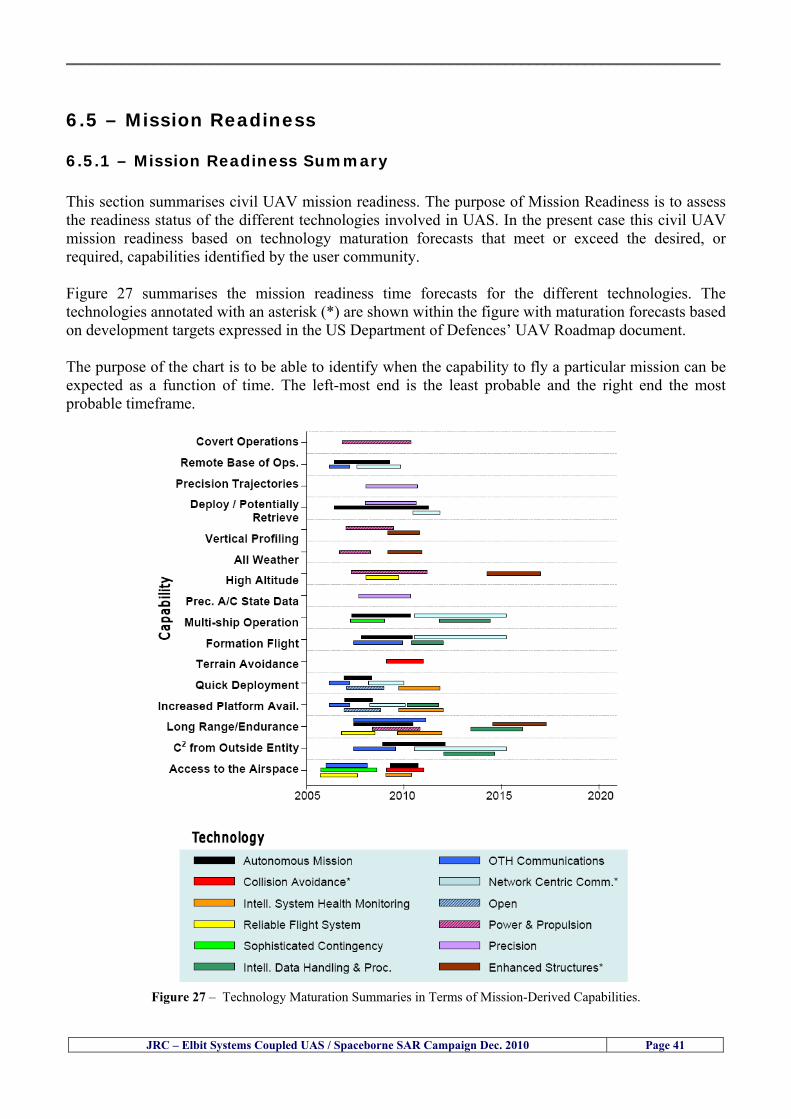
__________________________________________________________________________________
JRC ndash Elbit Systems Coupled UAS Spaceborne SAR Campaign Dec 2010 Page 41
65 ndash Mission Readiness
651 ndash Mission Readiness Summary This section summarises civil UAV mission readiness The purpose of Mission Readiness is to assess the readiness status of the different technologies involved in UAS In the present case this civil UAV mission readiness based on technology maturation forecasts that meet or exceed the desired or required capabilities identified by the user community Figure 27 summarises the mission readiness time forecasts for the different technologies The technologies annotated with an asterisk () are shown within the figure with maturation forecasts based on development targets expressed in the US Department of Defencesrsquo UAV Roadmap document The purpose of the chart is to be able to identify when the capability to fly a particular mission can be expected as a function of time The left-most end is the least probable and the right end the most probable timeframe
Figure 27 ndash Technology Maturation Summaries in Terms of Mission-Derived Capabilities
__________________________________________________________________________________
JRC ndash Elbit Systems Coupled UAS Spaceborne SAR Campaign Dec 2010 Page 42
66 ndash Small Boat Detection in SAR Satellite Imagery The use of spaceborne SAR imagery for small boat detection requires additional small boat detection experiments under different conditions using different methods It is not possible to draw final conclusions based on a limited number of small boat detection experiments which are not representative of the multiple possible scenarios
67 ndash Limitations of current State-of-the-Art SAR Satellite technology The main limitations of current State-of-the-Art spaceborne SAR imagery for maritime surveillance in particular aimed at small boat detection are 1 - SAR satellites repeat cycles do not allow the coverage of the same area at the required time intervals Constellations of SAR satellites could be a solution 2 - The conflict between resolution and image swath High resolution is required to detect small boats However the high resolution images have small swaths Maritime surveillance with high resolution images would require a large number of images to cover wide maritime areas which is very expensive and for the time being technically not feasible Intelligence data can play an important role by indicating an approximate position of suspicious non cooperative targets therefore reducing the surveillance area which can then be imaged using high resolution images 3- Spaceborne high resolution SAR imagery acquisition times are long enough to allow significant motion of the target during the acquisition time degrading the quality of the image Further research efforts are needed to develop new sensors and platforms As far as sensors are concerned shorter integration times are needed to prevent the blurring effect caused by the motion of the targets Regarding the platforms more platforms are needed to allow lower repeat cycles and improved coverage
__________________________________________________________________________________
JRC ndash Elbit Systems Coupled UAS Spaceborne SAR Campaign Dec 2010 Page 43
7 ndash Plans for Future Work The controlled experiments carried out by the EC-JRC together with Elbit Systems in Haifa-Israel comprised the deployment of a UAS (Hermes-450) and one small 12-meter boat A Radarsat-2 Spotlight image was acquired and several images collected by the Hermes-450 The experiment unveiled the potential of UAS for maritime surveillance in particular for detection tracking classification and possible identification of small targets The UAS was able to detect track and classify small targets such as small boats For low UAS altitude flights identification may be possible in some cases The small 12-meter boat was detected in the spaceborne SAR image The small boat detection trials carried out by the JRC were very successful since most small boats deployed during the experiments were detected in different sea states wind speeds and geographical locations The several small boat detection campaigns conducted by the EC-JRC seem to suggest that the probability of detection of small boats in spaceborne SAR images strongly depends on factors such as the sea state the wind speed the type of boat (shape and materials) the weather conditions among other factors The results of the experiments conducted thus far are not enough to draw final conclusions about the feasibility of using spaceborne SAR imagery for small boat detection However the experiments have an overall positive outcome because they indicate that under suitable sea state and wind speed conditions it is possible to detect small boats using spaceborne SAR The estimation of the probability of detection of small boats in spaceborne SAR images requires a large number of experiments under different circumstances (eg sea state wind speed characteristics of the targets image type and mode etc) Future plans include additional UAS experiments to asses its potential for maritime surveillance
Acknowledgements ndash The authors would like to express their gratitude to Elbit Systems for their cooperation logistical support and assets deployed without which the present coupled UASSAR Satellite Small Boat Detection Campaign would have not been possible
__________________________________________________________________________________
JRC ndash Elbit Systems Coupled UAS Spaceborne SAR Campaign Dec 2010 Page 44
REFERENCES [1] Elbit Systems ldquoUAV Elbit Systems Proposal for Unmanned Aerial Vehicle (UAV) flight to
collect Ground Truth data during a Maritime Surveillance Campaign and demonstrate UAV capabilities for Maritime Surveillancerdquo 2010
[2] ndash Cheryl Yuhas Suborbital Science Program Manager NASA Science Mission Directorate ldquoEarth Observations and the Role of UAVs A Capabilities Assessment Version 11rdquo Civil UAV Assessment Team httpwwwnasagovcentersdrydenresearchcivuavindexhtml August 2006
[3] ndash Document NIAG (SG75) NATO Industrial Advisory Group Study Group 75 Pre-Feasibility Study on UAV Autonomous Operations 2004
[4] ndash United States Department of Defence (DoD) Directive 50001 ldquoThe Defense Acquisition Systemrdquo and DoD Instruction 50002 ldquoOperation of the Defense Acquisition Systemrdquo
[5] ndash Mr James Ramage Mr Massimo Avalle Dr Erik Berglund Dr Luigi Crovella Mr Robert Frampton Dr Uwe Krogmann Mr Christian Ravat Mr Mike Robinson Dr Axel Schulte Dr Scott Wood ldquoRTO-TR-SCI-118 - Automation Technologies and Application Considerations for Highly Integrated Mission Systemsrdquo RTO-TR-SCI-118 AC323(SCI-118)TP204 January 2009
[6] Victor MG Silva Gilles Jurquet Gabriel Marchalot Maria TG Calzado Txema Soroa Juan Sancho Adam Koubek Harm Greidanus and Claudio Savarino ldquoWide Maritime Area Airborne Surveillance (WIMA2S) WP5 Final Reportrdquo WIMAAS WP5 FP7 Project 2008-2011 - ISBN-978-92-79-22801-8 (print) 978-92-79-22802-5 (PDF) ISSN-1018-5593 (print) 1831-9424 (online) EC-JRC Scientific Report JRC 70093 2012
[7] Victor MG Silva and Harm Greidanus ldquoSpaceborne SAR Small Boat Detection Campaign in Portugal and Spainrdquo EUR 25281 EN ISBN 978-92-79-22553-6 ISSN 1831-9424 (online) EC-JRC Scientific Report JRC68160 2012
[8] Goncalves Da Silva V Van Wimersma Greidanus H Hejmanowska B Loudjani P ldquoUAS Applications With Societal Benefits ndash JRCrsquos UAS-Related Activitiesrdquo 2011-2012 UAS Yearbook - UAS Unmanned Aircraft Systems - The Global Perspective 9 (9) 2011 p 127-129 JRC66600
[9] Goncalves Da Silva V Van Wimersma Greidanus H ldquoSmall boat detection using TerraSAR-X and Radarsat2 satellite imageryrdquo 4th TerraSAR-X Science Team Meeting 14 February 2011 DLR Oberpfaffenhofen (Germany) German Aerospace Center (DLR) (Organiser) 2011 JRC63663
[10] V Silva Harm Greidanus ldquoJRC - SAR Satellite Small Boat Detection Campaign - Portoroz ndash Sloveniardquo - ISBN-13 978-92-79-21476-9 ISSN (online) 1831-9424 EC-JRC Scientific Report JRC66835 2011
[11] V Silva Harm Greidanus ldquoJRC - SAR satellite small boat detection campaign - Algarve Portugalrdquo - ISBN-13 978-92-79-21265-9 ISSN (online) 1831-9424 ISSN (print) 1018-5593 EC-JRC Scientific Report JRC66631 2011
[12] ndash Goncalves Da Silva V Van Wimersma Greidanus H ldquoJRC-Frontex Spaceborne SAR Small Boat Detection Campaign ndash Italy amp Spainrdquo - ISBN-13 978-92-79-22213-9 ISSN (online) 1831-9424 EC-JRC Scientific Report JRC67517 2011
[13] - PW Vachon SJ Thomas J Cranton HR Edel and MD Henschel Validation of ship detection by the RADARSAT synthetic aperture radar and the Ocean Monitoring Workstation Canadian Journal of Remote Sensing 26(3)200ndash212 2000
[14] - Crisp D (2004) The state-of-the-art in ship detection in Synthetic Aperture Radar imagery DSTO Information Sciences Laboratory Australia
[15] - Joint Research Centre (JRC) of the European Community mdash IMPAST and DECLIMS web site httpintelligencejrcceceuintmarinefishindexhtm
[16] - McCandless SW Jackson CR (2004) Principles of Synthetic Aperture Radar Synthetic Aperture Radar Marine Users Manual NOAA Washington pp 1-23
[17] - Greidanus H (2008) Satellite Imaging for Maritime Surveillance of the European Seas Remote Sensing of the European Seas 343-358
European Commission
EUR 25346 EN --- Joint Research Centre --- Institute for the Protection and Security of the Citizen
Title JRC --- Elbit Systems Coupled UAS and Spaceborne SAR Campaign in Israel
Authors Victor MG Silva Harm Greidanus
Luxembourg Publications Office of the European Union
2012 --- v+44 pp --- 210 x 297 cm
EUR --- Scientific and Technical Research series --- ISSN 181-9424 (online) ISSN 1018-5593 (print)
ISBN 978-92-79-25020-0
doi10278828527
Abstract The European maritime area is one of Europersquos most important assets with regard to resources security and ultimately
prosperity of the Member States A significant part of Europersquos economy relies directly or indirectly on it It is not just the
shipping or fisheries industries and their related activities It is also shipbuilding and ports marine equipment and offshore
energy maritime and coastal tourism aquaculture submarine telecommunications blue biotech and the protection of the
marine environment The European maritime area faces several risks and threats posed by unlawful activities such as drugs
trafficking smuggling illegal immigration organised crime and terrorism Piracy in international waters also constitutes a threat
to Europe since it can disrupt the maritime transport chain These risks and threats can endanger human lives marine resources
and the environment as well as significantly disrupt the transport chain and global and local security It is anticipated that these
risks and threats will endure in the mid and long run In order to keep Europe as a world leader in the global maritime economy
an effective integratedinteroperable sustainable maritime surveillance system and situational awareness are needed
A significant number of unlawful maritime activities such as illegal immigration drugs trafficking smuggling piracy and
terrorism involve mainly small boats because small boats are faster and more difficult to detect using conventional means
Hence it is very important to find out the feasibility of using Unmanned Aerial Systems (UAS) for small boat detection tracking
classification and identification as well as to study the potential of UAS for maritime surveillance Since 2010 the EC-JRC has
carried out a number of UAS maritime surveillance campaigns to study the potential of UAS for maritime surveillance in
particular for small boat detection This report presents the results and conclusions of the JRC --- Elbit Systems Coupled UAS and
Spaceborne SAR campaign carried out in Dec 2010 in Haifa Israel
As the Commissionrsquos in-house science service the Joint Research Centrersquos mission is to provide EU policies with independent evidence-based scientific and technical support throughout the whole policy cycle Working in close cooperation with policy Directorates-General the JRC addresses key societal challenges while stimulating innovation through developing new standards methods and tools and sharing and transferring its know-how to the Member States and international community Key policy areas include environment and climate change energy and transport agriculture and food security health and consumer protection information society and digital agenda safety and security including nuclear all supported through a cross-cutting and multi-disciplinary approach
LB-NA-25346-EN
-N
__________________________________________________________________________________
JRC ndash Elbit Systems Coupled UAS Spaceborne SAR Campaign Dec 2010 Page 44
REFERENCES [1] Elbit Systems ldquoUAV Elbit Systems Proposal for Unmanned Aerial Vehicle (UAV) flight to
collect Ground Truth data during a Maritime Surveillance Campaign and demonstrate UAV capabilities for Maritime Surveillancerdquo 2010
[2] ndash Cheryl Yuhas Suborbital Science Program Manager NASA Science Mission Directorate ldquoEarth Observations and the Role of UAVs A Capabilities Assessment Version 11rdquo Civil UAV Assessment Team httpwwwnasagovcentersdrydenresearchcivuavindexhtml August 2006
[3] ndash Document NIAG (SG75) NATO Industrial Advisory Group Study Group 75 Pre-Feasibility Study on UAV Autonomous Operations 2004
[4] ndash United States Department of Defence (DoD) Directive 50001 ldquoThe Defense Acquisition Systemrdquo and DoD Instruction 50002 ldquoOperation of the Defense Acquisition Systemrdquo
[5] ndash Mr James Ramage Mr Massimo Avalle Dr Erik Berglund Dr Luigi Crovella Mr Robert Frampton Dr Uwe Krogmann Mr Christian Ravat Mr Mike Robinson Dr Axel Schulte Dr Scott Wood ldquoRTO-TR-SCI-118 - Automation Technologies and Application Considerations for Highly Integrated Mission Systemsrdquo RTO-TR-SCI-118 AC323(SCI-118)TP204 January 2009
[6] Victor MG Silva Gilles Jurquet Gabriel Marchalot Maria TG Calzado Txema Soroa Juan Sancho Adam Koubek Harm Greidanus and Claudio Savarino ldquoWide Maritime Area Airborne Surveillance (WIMA2S) WP5 Final Reportrdquo WIMAAS WP5 FP7 Project 2008-2011 - ISBN-978-92-79-22801-8 (print) 978-92-79-22802-5 (PDF) ISSN-1018-5593 (print) 1831-9424 (online) EC-JRC Scientific Report JRC 70093 2012
[7] Victor MG Silva and Harm Greidanus ldquoSpaceborne SAR Small Boat Detection Campaign in Portugal and Spainrdquo EUR 25281 EN ISBN 978-92-79-22553-6 ISSN 1831-9424 (online) EC-JRC Scientific Report JRC68160 2012
[8] Goncalves Da Silva V Van Wimersma Greidanus H Hejmanowska B Loudjani P ldquoUAS Applications With Societal Benefits ndash JRCrsquos UAS-Related Activitiesrdquo 2011-2012 UAS Yearbook - UAS Unmanned Aircraft Systems - The Global Perspective 9 (9) 2011 p 127-129 JRC66600
[9] Goncalves Da Silva V Van Wimersma Greidanus H ldquoSmall boat detection using TerraSAR-X and Radarsat2 satellite imageryrdquo 4th TerraSAR-X Science Team Meeting 14 February 2011 DLR Oberpfaffenhofen (Germany) German Aerospace Center (DLR) (Organiser) 2011 JRC63663
[10] V Silva Harm Greidanus ldquoJRC - SAR Satellite Small Boat Detection Campaign - Portoroz ndash Sloveniardquo - ISBN-13 978-92-79-21476-9 ISSN (online) 1831-9424 EC-JRC Scientific Report JRC66835 2011
[11] V Silva Harm Greidanus ldquoJRC - SAR satellite small boat detection campaign - Algarve Portugalrdquo - ISBN-13 978-92-79-21265-9 ISSN (online) 1831-9424 ISSN (print) 1018-5593 EC-JRC Scientific Report JRC66631 2011
[12] ndash Goncalves Da Silva V Van Wimersma Greidanus H ldquoJRC-Frontex Spaceborne SAR Small Boat Detection Campaign ndash Italy amp Spainrdquo - ISBN-13 978-92-79-22213-9 ISSN (online) 1831-9424 EC-JRC Scientific Report JRC67517 2011
[13] - PW Vachon SJ Thomas J Cranton HR Edel and MD Henschel Validation of ship detection by the RADARSAT synthetic aperture radar and the Ocean Monitoring Workstation Canadian Journal of Remote Sensing 26(3)200ndash212 2000
[14] - Crisp D (2004) The state-of-the-art in ship detection in Synthetic Aperture Radar imagery DSTO Information Sciences Laboratory Australia
[15] - Joint Research Centre (JRC) of the European Community mdash IMPAST and DECLIMS web site httpintelligencejrcceceuintmarinefishindexhtm
[16] - McCandless SW Jackson CR (2004) Principles of Synthetic Aperture Radar Synthetic Aperture Radar Marine Users Manual NOAA Washington pp 1-23
[17] - Greidanus H (2008) Satellite Imaging for Maritime Surveillance of the European Seas Remote Sensing of the European Seas 343-358
European Commission
EUR 25346 EN --- Joint Research Centre --- Institute for the Protection and Security of the Citizen
Title JRC --- Elbit Systems Coupled UAS and Spaceborne SAR Campaign in Israel
Authors Victor MG Silva Harm Greidanus
Luxembourg Publications Office of the European Union
2012 --- v+44 pp --- 210 x 297 cm
EUR --- Scientific and Technical Research series --- ISSN 181-9424 (online) ISSN 1018-5593 (print)
ISBN 978-92-79-25020-0
doi10278828527
Abstract The European maritime area is one of Europersquos most important assets with regard to resources security and ultimately
prosperity of the Member States A significant part of Europersquos economy relies directly or indirectly on it It is not just the
shipping or fisheries industries and their related activities It is also shipbuilding and ports marine equipment and offshore
energy maritime and coastal tourism aquaculture submarine telecommunications blue biotech and the protection of the
marine environment The European maritime area faces several risks and threats posed by unlawful activities such as drugs
trafficking smuggling illegal immigration organised crime and terrorism Piracy in international waters also constitutes a threat
to Europe since it can disrupt the maritime transport chain These risks and threats can endanger human lives marine resources
and the environment as well as significantly disrupt the transport chain and global and local security It is anticipated that these
risks and threats will endure in the mid and long run In order to keep Europe as a world leader in the global maritime economy
an effective integratedinteroperable sustainable maritime surveillance system and situational awareness are needed
A significant number of unlawful maritime activities such as illegal immigration drugs trafficking smuggling piracy and
terrorism involve mainly small boats because small boats are faster and more difficult to detect using conventional means
Hence it is very important to find out the feasibility of using Unmanned Aerial Systems (UAS) for small boat detection tracking
classification and identification as well as to study the potential of UAS for maritime surveillance Since 2010 the EC-JRC has
carried out a number of UAS maritime surveillance campaigns to study the potential of UAS for maritime surveillance in
particular for small boat detection This report presents the results and conclusions of the JRC --- Elbit Systems Coupled UAS and
Spaceborne SAR campaign carried out in Dec 2010 in Haifa Israel
As the Commissionrsquos in-house science service the Joint Research Centrersquos mission is to provide EU policies with independent evidence-based scientific and technical support throughout the whole policy cycle Working in close cooperation with policy Directorates-General the JRC addresses key societal challenges while stimulating innovation through developing new standards methods and tools and sharing and transferring its know-how to the Member States and international community Key policy areas include environment and climate change energy and transport agriculture and food security health and consumer protection information society and digital agenda safety and security including nuclear all supported through a cross-cutting and multi-disciplinary approach
LB-NA-25346-EN
-N
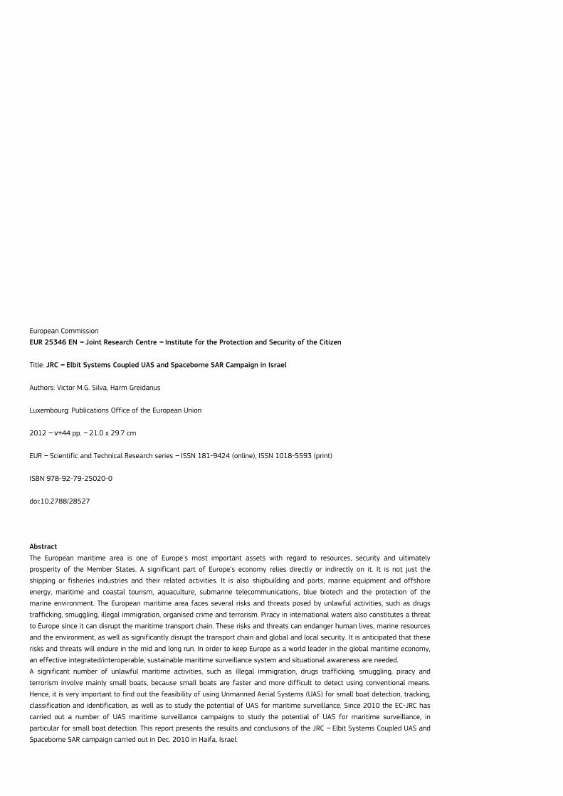