Embed Size (px)
Citation preview

Jover Rodríguez, P., Arkkio, A., 2008, Detection of Stator Winding Fault in InductionMotor Using Fuzzy Logic, Applied Soft Computing, Vol. 8, No. 2, pp. 11121120.
© 2008 by authors and © 2008 Elsevier Science
Preprinted with permission from Elsevier.
Detection of Stator Winding Fault In Induction Motor Using Fuzzy Logic
Pedro Vicente Jover Rodríguez
Antero Arkkio
Laboratory of Electromechanics
Helsinki University of Technology
P.O. Box 3000, 02015 HUT, Finland
Phone: +358 9 4512391, Fax: +358 9 4512991 [email protected]
Abstract
The online monitoring of induction motors is becoming increasingly important. The main difficulty in
this task is the lack of an accurate analytical model to describe a faulty motor. A fuzzy logic approach
may help to diagnose induction motor faults. This work presents a reliable method for the detection of
stator winding faults (which make up 38% of induction motor failures) based on monitoring the
line/terminal current amplitudes. In this method, fuzzy logic is used to make decisions about the stator
motor condition. The fuzzy system is based on knowledge expressed in rules and membership
functions, which describe the behaviour of the stator winding. The Finite Element Method (FEM) is
utilised to generate virtual data that support the construction of the membership functions and give the
possibility to online test the proposed system. The layout has been implemented in
MATLAB/SIMULINK, with both data from a FEM motor simulation program and real measurements.
The proposed method is simple and has the ability to work with variable speed drives. The fuzzy
system is able to identify the motor stator condition with high accuracy. This work is an example of
the fusion between soft and hard computing.
Key words
Induction motor, fuzzy logic, winding fault, current, detection.
2
1. Introduction Three-phase induction motors are the “workhorses” of industry and are the most widely used
electrical machine. Because of its simple structure and high reliability, induction motor is used for
many purposes such as: pumps, blowers, fans, compressors, transportation, etc. In an industrialised
nation, they can consume between 40 to 50 % of total generated capacity of that country [3,15].
However, owing to the thermal, electrical and mechanical stresses, mechanical and electrical
failures are unavoidable in induction motors. Early detection of abnormalities in the motor will help to
avoid expensive failures. Operators of electric drive systems are under continual pressure to reduce
maintenance costs and prevent unscheduled downtimes that result in lost production and loss of
financial income.
The modern industry has widely used reliability-based and condition-based maintenance strategies
to reduce unexpected failures and downtime. These techniques can increase the time between planned
shutdowns for standard maintenance and reduce maintenance and operational costs. The operation of
the machine in unsafe condition must also be avoided. Nevertheless, the failures are unavoidable, and
failure statistics [15] has reported that the percentage of failures in induction motor components is as
follows:
1. Bearing related faults: 40%
2. Stator winding related faults: 38%
3. Rotor related faults: 10%
4. Other faults: 12%
It is important to note that even if the stator fault account makes up 38 % of the all faults, it is very
important to spot them in time because they can lead to the total destruction of the motor. A reliable
system for the detection of such a fault should be able to detect the fault at an early stage, monitoring
the motor condition online.
3
The fuzzy logic approach may help to diagnose induction motor faults. The concept of fuzzy
logic was introduced by Professor Lofti A. Zadeh to present vagueness in linguistic terms and express
human knowledge in a natural way [16]. It is well known that fuzzy logic can describe the
characteristics of industrial process with linguistic terms [11]. The motor condition identification task
requires the interpretation of data and makes decision from the data. Primarily, the motor condition
constitutes a fuzzy set. In practice, the users are concerned about the condition of the motor in terms of
a linguistic variable that can be expressed as “good”, “damaged” or “seriously damaged”. Further, a
fuzzy system can store certain knowledge, which allows it to make decisions with a high percent of
accuracy. This knowledge expressed in rules and membership functions is obtained from the analytical
study of the motor, motor performance, simulated data and power engineer experience. From the point
of view that sees induction motor condition as a fuzzy concept, there has been some fuzzy logic
approaches for diagnosis. The lack of proper processing of fuzzy input data and the construction of the
membership functions are presented as the major difficulties [4, 7, 11, 12]. This problem is tackled in
this work by using FEM in order to generate reliable virtual data, which allows the construction of the
membership functions in all faulty and load conditions.
The aim of FEM here is to foresee the changes of motor performance due to the changes in the
internal parameters when the motor is working under faulty conditions. Numerical simulations
generate useful data, which are used to test the diagnostic techniques. FEM permits the evaluation of
the influence of different motor faults in an inexpensive and accurate manner [14].
Early work in the detection of induction motor faults using fuzzy logic is presented in [12]. This
application corresponds to single phase induction motors. This paper suggests the application of the
approach to other different machines by forming appropriate membership functions and rules knowing
the machine behaviour. It is suggested that the rules should be known experimentally and with the help
of an expert. This paper presents some guidelines for the derivation or rules.
4
Recently, some applications of fuzzy logic for the detection of faults in electrical machines and
power electronic have emerged as a solution for online diagnosis. In reference [5] a neuro fuzzy
system for the detection of faults in power transformer is presented. Reference [10] presents a system
for detecting online fault in HVAC systems, where the fuzzy system is assisted by genetic algorithm to
generate optimal rules. In both cases automated online diagnosis have been achieved. Reference [2]
presents an adaptive neural fuzzy inference system (ANFIS) for the detection of winding and bearing
faults in single-phase induction motors. In [2] experimental data is generated for five measurable
different parameters, which constitute the inputs for the ANFIS detector. Such a synergy, between
neural network, brings a better understanding of the heuristics and motor fault detection can be
achieved. But still the main drawback the of all data-based identification methods remains: the
performance of the classification can be only as good as the data it is based on. In fault classification
this may be a problem, because often there are not much reliable data available from all the faulty
operations. Further, another major difficulty in motor-fault detection and diagnosis is the lack of an
accurate analytical model that describes a faulty motor.
In our research, fuzzy logic approach is used to make decisions about the motor condition. The task
of the diagnostic system presented in this work is to detect an upcoming stator fault as early as
possible, in order to save expensive manufacturing processes or to replace faulty parts. Since stator
faults do not produce clear signatures in the current spectrum, it is necessary to use other means to
identify stator faults instead of the traditional spectrum analysis technique. For that reason the fuzzy
logic approach is applied to the motor current amplitudes in order to spot failures in the stator. The
terminal current amplitudes contain potential fault information and constitute suitable measurements
for diagnosing stator faults in term of easy accessibility, reliability and sensitivity [4].
5
2. Stator winding fault In low voltage three-phase induction motors the stator-winding fault can be classified as follow:
1- Turn to turn shorts within a coil (inter-turn short circuit): motor will continue to operate, but for
how long?
2- Shorts between coils of the same phase, motor can continue to operate but for how long?
3- Phase to phase short, motor fails and protection equipment disconnects the supply.
4-Phase to earth short: motor fails and protection equipment disconnects the supply.
5-Open circuit in one phase, motor may continue to operate, depending on the load conditions.
Pre-warning of motor failure, such as 3 and 4 can only be achieved if shorted turns within a coil
(such as 1) can be initially diagnosed via online diagnostic technique. The general opinion of the users
and manufactures is that there is a longer lead-time between the inception of shorted turns up to failure
in low voltage motors. In modern production process, any lead-time can be extremely advantageous
since unexpected failures of a drive can be very costly. If an inter-turn short (one or two shorted turns)
can be diagnosed, a pre-planned shutdown can be arranged.
The common technique for online detection of motor faults is known as motor current signature
analysis (MCSA) [15]. The objective of this technique is to detect certain components in the stator
current spectrum that are only a function of a specific fault. However, it has been shown
mathematically and experimentally by [9] that the spectral components due shorted turns are not a
reliable indicator of stator winding fault.
In reference [9], the interaction between a faulted stator winding and healthy rotor cage is studied.
The faulted, asymmetric stator winding may produce spatial harmonics of any wave number into the
air-gap field. However, all these harmonics vary at a single frequency, i.e. the supply frequency of the
sinusoidal voltage source. The stator harmonics induce currents in the rotor cage and reflect back from

6
the rotor as new air-gap field harmonics. Seen from the stator, the air-gap harmonics caused by the
induced rotor currents vary at the frequencies
( )rf 1 1 1nf f spλ⎡ ⎤
= ± −⎢ ⎥⎣ ⎦
(1)
rff components reflected from the stator side, so-called rotor slot harmonics
1f supply frequency
p number of pole-pairs
s slip
n number of rotor bars
...3,2,1=λ
The air-gap field harmonics induce electromotive forces in the stator winding and generate harmonic
stator currents at these same frequencies. Unfortunately, these are the same frequencies at which a
healthy machine produces harmonic stator currents.
According to this analysis, a stator fault may only generate harmonic stator currents, which vary at
the fundamental and rotor-slot harmonic frequencies. A fault in a stator winding may change the
amplitudes of the stator-current harmonics but it does not produce any new frequencies in the stator-
current spectrum. This significant result implies that it may be difficult to detect a stator fault from a
current spectrum using MCSA. Then, another technique is needed to spot this important fault.
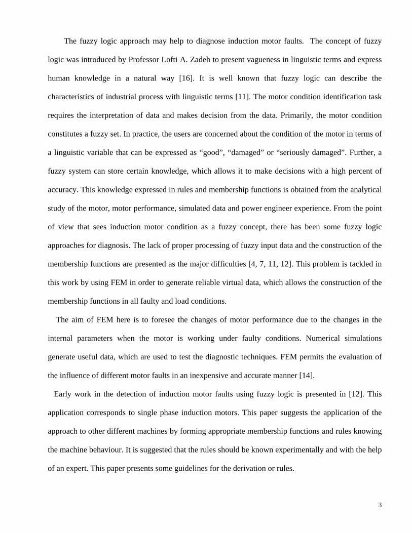
A healthy three phases induction motor fed from a symmetric power supply has three balanced
phase currents. Fig. 1 shows the phase currents of a healthy motor working at half load and fed from
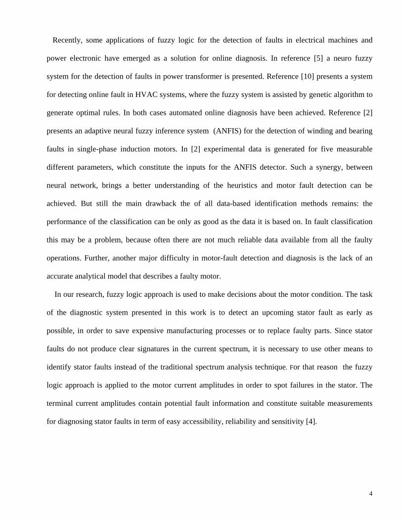
an inverter at 100 Hz. The induction motor is ideally a symmetry system. Any asymmetric in the
stator winding produces unbalance in the motor currents. The most difficult case to identify might be
when there is only inter-turn short circuit, as is shown in Fig. 2, where the lowest unbalanced is shown.
Fig. 1 and Fig. 2 correspond to measured data. The main idea of the developed monitoring system is to
7
spot the unbalance in the input currents as fast as possible avoiding a major failure. The system should
be able also to detect a short-circuited coil and open phase.
Fig. 1. Terminal phase currents in a healthy motor. Inverter supply at 100 Hz
Fig. 2. Terminal phase currents in a faulty motor during an inter-turn short circuit. Inverter supply at
100 Hz.
3. Generating of data by FEM
8
In our software package, FEM is applied for solving electromagnetic problems, which are described
by the Maxwell equations. This software is an in-house 2-D FEM program, in which the magnetic
field in the cross-section area of the test machine is computed. This package was designed for the
transient magnetic field analysis of electrical machines coupled with the circuit equations of the
machine windings. This method allows the simulation of electrical machine fed from measured
voltages of the power converter used in experiments. The software uses the time-stepping method,
which takes into account the motion of the rotor and the induced voltage due to this motion. Some of
the 3-D effects like flux fringing and end windings are also modelled with analytical and electric
circuit approaches. A full description of the software and its accuracy is given in [1]. A detailed
description about fault implementation in the program can be found in [14].
The FEM program permits the generation of data with the motor working in different condition of
load as well as changing the severity of the fault. Data were generated for healthy motor, inter-turn
short-circuits and inter-coil short-circuits. In every case three load conditions full, half and no load
were considered. The membership functions are obtained from the calculated current, taking into
account the healthy and faulty conditions.
4. Detection system
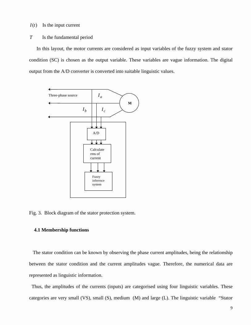
A block diagram of the system can be seen in Fig. 3. The system monitors the amplitudes of the
motor currents ,a bI I and cI . Firstly, the analogic measurements are converted in digital data through
an A/D converter. Then, the root mean square (rms) of each phase current is calculated over a period
of time using the standard formula,
∫+
=Tt
tdttI
Trms 2)(1
(2)
9
)(tI Is the input current
T Is the fundamental period
In this layout, the motor currents are considered as input variables of the fuzzy system and stator
condition (SC) is chosen as the output variable. These variables are vague information. The digital
output from the A/D converter is converted into suitable linguistic values.
Fig. 3. Block diagram of the stator protection system.
4.1 Membership functions
The stator condition can be known by observing the phase current amplitudes, being the relationship
between the stator condition and the current amplitudes vague. Therefore, the numerical data are
represented as linguistic information.
Thus, the amplitudes of the currents (inputs) are categorised using four linguistic variables. These
categories are very small (VS), small (S), medium (M) and large (L). The linguistic variable “Stator
M
Three-phase source
A/D
Calculate rms of current
Fuzzy inference system
aI
bI cI
10
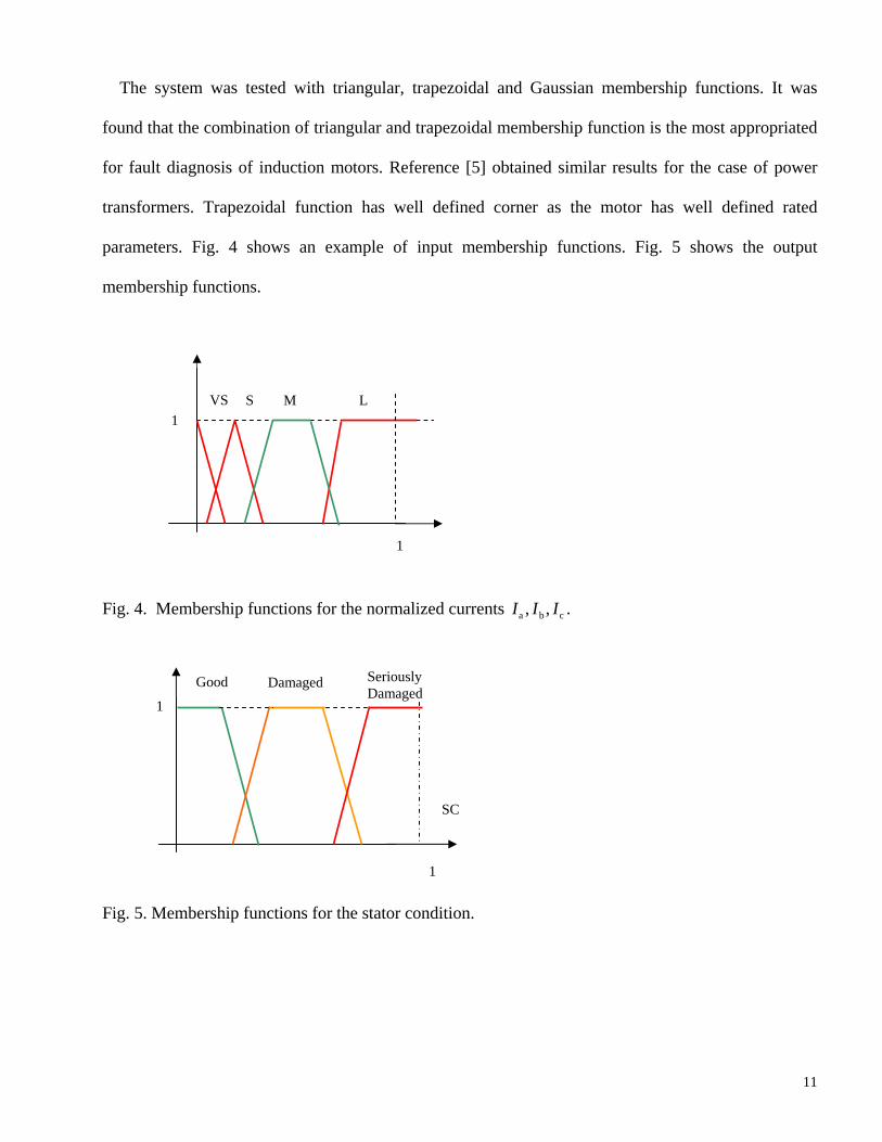
condition” (SC) (output), interpreting the stator condition could be “Good” (G), “Damaged”(D) or
“Seriously damaged” (SD). “G” refers to a stator with no faults, “D” might be a stator with current
unbalance (inter-turn short circuit), and “SD” a stator with an open phase or coil short-circuited. In
other words and using fuzzy logic theory, the input and output of the system are defined as,
Inputs: { }aajajIa IiiIa
∈= /)(µ (3)
{ }bbjbjIb IiiIb
∈= /)(µ (4)
{ }ccjcjIc IiiIc
∈= /)(µ (5)
Output: { }SCscscSC jjSC ∈= /)(µ (6)
, ,aj bj cji i i , jsc are elements of the discrete universe of discourse
a b c, ,I I I , SC are universe of discourse
SCIII cbaµµµµ ,,, are corresponding membership functions
(SC)T Term interpreting the stator condition: can be good, damaged or seriously
damaged
The membership functions for the input and output variables are constructed by the analysis of data
generated by FEM. Thus, the FEM program is run from no-load to full-load in the healthy situation
and the rms values of the phase currents are calculated, obtaining values from 25 to 65 A (for the case
of motor 1). These values are normalized between [0, 1], defining the membership function which
corresponds with the linguistic term M, for a healthy motor. Similar process is repeated for the faulty
conditions, defining the VS, S, and L. The VS condition is obtained when the motor has a fully open
phase, L corresponds to a short-circuit in one phase and S corresponds with a no load motor. All
these situations are simulated in FEM, allowing the definition of the trapezoidal membership
functions.
11
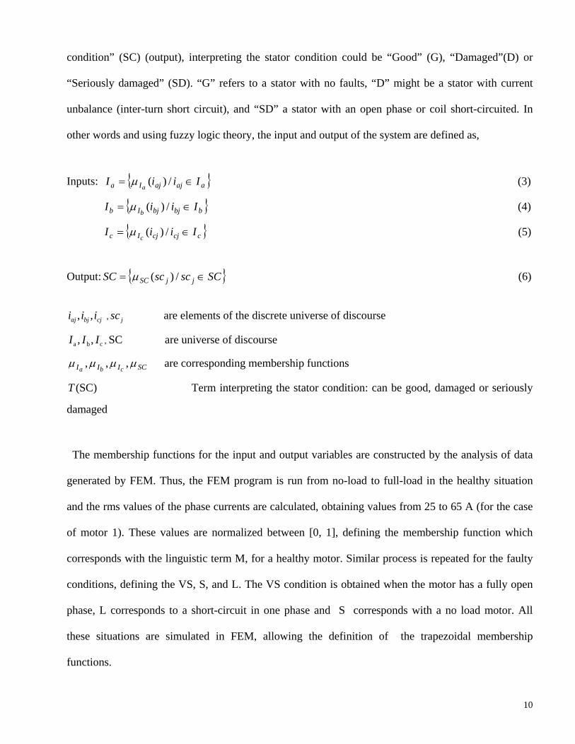
The system was tested with triangular, trapezoidal and Gaussian membership functions. It was
found that the combination of triangular and trapezoidal membership function is the most appropriated
for fault diagnosis of induction motors. Reference [5] obtained similar results for the case of power
transformers. Trapezoidal function has well defined corner as the motor has well defined rated
parameters. Fig. 4 shows an example of input membership functions. Fig. 5 shows the output
membership functions.
Fig. 4. Membership functions for the normalized currents a b c, ,I I I .
Fig. 5. Membership functions for the stator condition.
SC
Seriously Damaged
Good Damaged
1
1
1
VS S M L1

12
Another known power engineer fact is included that takes into account the amplitude variance, in
order to improve the system sensitivity and reliability. The membership function for the amplitude
“variance” of current is shown in Fig. 6. The variance is calculated as follow,
2 2 2
2a b cI I I I I I
v− + − + −
= (3)
where , ,a b cI I I are the rms values of the input currents
Fig. 6. Membership functions of the variable “variance”.
The membership function of the variance is also defined from the FEM calculation and
normalized between [0, 1]. The amplitudes of the currents as well as the variance are transferred into
the corresponding universe of discourse as inputs. The fuzzy inference engine evaluates the inputs
based on power engineer experience.
4.2 Inference system
The design of rules in our case is based on the expert understanding. The process consists of two
parts: knowledge acquisition and formation of rules and combination of rules. Our inference system
will perform as a power engineer with an ammeter.
The knowledge acquisition starts, with the translation of the motor understanding to if-then rules.
Firstly, it is important to remember that a three phase healthy induction motor is a symmetric system.
Normal Large1
1
13
This is equivalent to say that the three currents have the same rms values (within a tolerance), this
define the healthy situation, rules 9 and 10. On the other hand, it is enough that one of the phase
currents is large (L) to imply the motor is seriously damage, rules 4, 5, 6. Moreover, it is also enough
that one of the currents is very small (VS) to imply that the motor is seriously damage (SD). Totally,
we have in the input of the system 64 possible combinations between the three currents and the four
categories for every current. Many of the combinations are redundant. For example, if the three
currents are large, the SC is seriously damage, but this condition is already included in one of the rules
4 or 5 or 6. Similarly happens when we have two large currents. This analysis is manually extended to
cover all the combinations.
From the optimisation of all different possible combinations between the three currents and four
linguistic variables the following set of rules is obtained. This set of rules contains the knowledge and
description of the machine condition. They are universal for all three phases induction motors.
Rule 1: If aI is VS then SC is SD
Rule 2: If bI is VS then SC is SD
Rule 3: If cI is VS then SC is SD
Rule 4: If aI is L then SC is SD
Rule 5: If bI is L then SC is SD
Rule 6: If cI is L then SC is SD
Rule 7: If aI is S and bI is S and cI is M then SC is D
Rule 8: If aI is S and bI is M and cI is M then SC is D
Rule 9: If aI is M and bI is S and cI is M then SC is D
Rule 10: If aI is M and bI is M and cI is M then SC is G
Rule 11: If aI is S and bI is S and cI is S then SC is G
Rule 12: If aI is S and bI is M and cI is S then SC is D
14
Rule 13: If aI is M and bI is S and cI is S then SC is D
Rule 14: If aI is M and bI is M and cI is S then SC is D
Rule 15: If v is L then SC is D In the final stage, the fuzzy actions are reconverted in crisp ones by using the center of area method.
According to this method, each affected output membership is cut at the level indicated by the
previous max-rule, then the gravity center of the possible distribution is computed and becomes the
numerical output value [11].
4. Simulation results
Two different motors, a 15 kW delta connected and 35 kW star connected machines were studied.
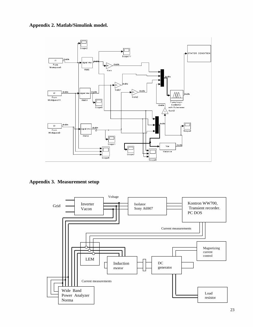
The parameters are given in Appendix 1. The SIMULINK model of the fault detection system is
shown in Appendix 2. The model is implemented online with the data.
The fault detection method was first tested online with data from FEM motor simulation program.
As the FEM program takes into account the non-linearity and inhomogeneous characteristics of the
materials, it is a good approximation to the actual motor. The sampling frequency in the FEM
simulation program was 40 kHz and the number of samples simulated was 10 000. The simulation
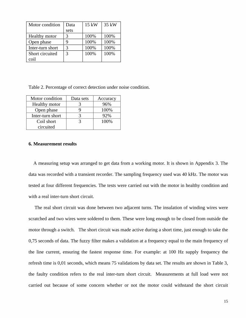
model was able to identify the fault with excellent accuracy as can be seen in Table 1.
During every data set, the fuzzy filter executes 25 validations of the stator condition. The duration
time of every data set was 0.25 seconds. The test was carried out with the motor in three different load
conditions, no-load, half-load and full-load. In order to prove the performance of the SIMULINK
model under noise condition, a source of noise was added to each phase. Table 2 shows the results
under noisy condition.
Table 1. Percentage of correct detection from simulated data
15
Motor condition Data sets
15 kW 35 kW
Healthy motor 3 100% 100% Open phase 9 100% 100% Inter-turn short 3 100% 100% Short circuited coil
3 100% 100%
Table 2. Percentage of correct detection under noise condition.
Motor condition Data sets Accuracy Healthy motor 3 96%
Open phase 9 100% Inter-turn short 3 92%
Coil short circuited
3 100%
6. Measurement results
A measuring setup was arranged to get data from a working motor. It is shown in Appendix 3. The
data was recorded with a transient recorder. The sampling frequency used was 40 kHz. The motor was
tested at four different frequencies. The tests were carried out with the motor in healthy condition and
with a real inter-turn short circuit.
The real short circuit was done between two adjacent turns. The insulation of winding wires were
scratched and two wires were soldered to them. These were long enough to be closed from outside the
motor through a switch. The short circuit was made active during a short time, just enough to take the
0,75 seconds of data. The fuzzy filter makes a validation at a frequency equal to the main frequency of
the line current, ensuring the fastest response time. For example: at 100 Hz supply frequency the
refresh time is 0,01 seconds, which means 75 validations by data set. The results are shown in Table 3,
the faulty condition refers to the real inter-turn short circuit. Measurements at full load were not
carried out because of some concern whether or not the motor could withstand the short circuit
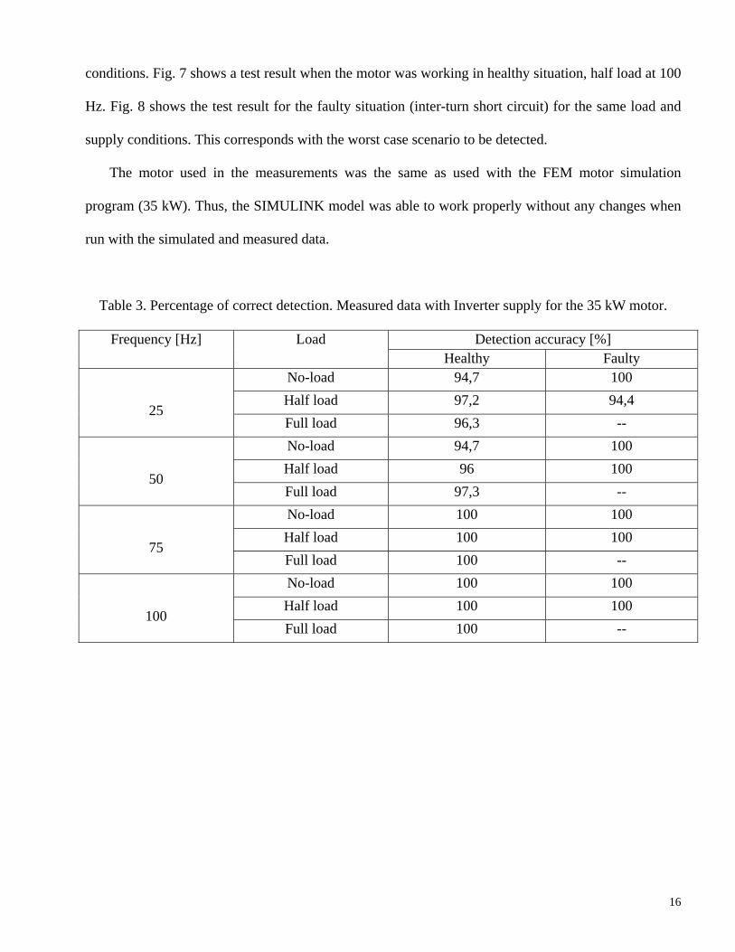
16
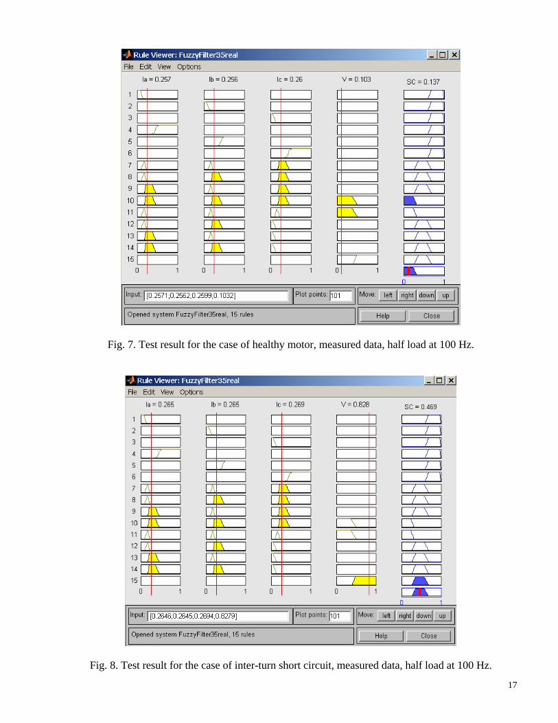
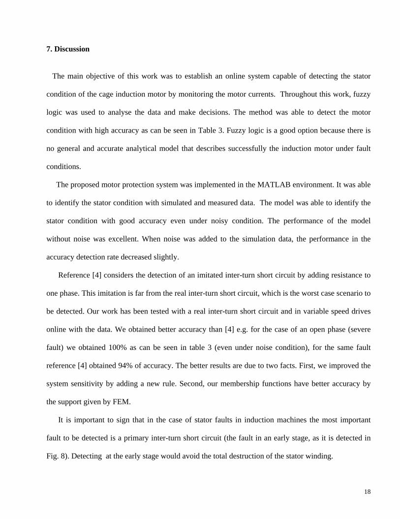
conditions. Fig. 7 shows a test result when the motor was working in healthy situation, half load at 100
Hz. Fig. 8 shows the test result for the faulty situation (inter-turn short circuit) for the same load and
supply conditions. This corresponds with the worst case scenario to be detected.
The motor used in the measurements was the same as used with the FEM motor simulation
program (35 kW). Thus, the SIMULINK model was able to work properly without any changes when
run with the simulated and measured data.
Table 3. Percentage of correct detection. Measured data with Inverter supply for the 35 kW motor.
Detection accuracy [%] Frequency [Hz] Load Healthy Faulty
No-load 94,7 100 Half load 97,2 94,4
25 Full load 96,3 -- No-load 94,7 100 Half load 96 100
50 Full load 97,3 -- No-load 100 100 Half load 100 100
75 Full load 100 -- No-load 100 100 Half load 100 100
100 Full load 100 --
17
Fig. 7. Test result for the case of healthy motor, measured data, half load at 100 Hz.
Fig. 8. Test result for the case of inter-turn short circuit, measured data, half load at 100 Hz.
18
7. Discussion
The main objective of this work was to establish an online system capable of detecting the stator
condition of the cage induction motor by monitoring the motor currents. Throughout this work, fuzzy
logic was used to analyse the data and make decisions. The method was able to detect the motor
condition with high accuracy as can be seen in Table 3. Fuzzy logic is a good option because there is
no general and accurate analytical model that describes successfully the induction motor under fault
conditions.
The proposed motor protection system was implemented in the MATLAB environment. It was able
to identify the stator condition with simulated and measured data. The model was able to identify the
stator condition with good accuracy even under noisy condition. The performance of the model
without noise was excellent. When noise was added to the simulation data, the performance in the
accuracy detection rate decreased slightly.
Reference [4] considers the detection of an imitated inter-turn short circuit by adding resistance to
one phase. This imitation is far from the real inter-turn short circuit, which is the worst case scenario to
be detected. Our work has been tested with a real inter-turn short circuit and in variable speed drives
online with the data. We obtained better accuracy than [4] e.g. for the case of an open phase (severe
fault) we obtained 100% as can be seen in table 3 (even under noise condition), for the same fault
reference [4] obtained 94% of accuracy. The better results are due to two facts. First, we improved the
system sensitivity by adding a new rule. Second, our membership functions have better accuracy by
the support given by FEM.
It is important to sign that in the case of stator faults in induction machines the most important
fault to be detected is a primary inter-turn short circuit (the fault in an early stage, as it is detected in
Fig. 8). Detecting at the early stage would avoid the total destruction of the stator winding.
19
We also tested the layout for both, the delta and star connections. For both cases, the detection
accuracy were good. The model showed that comparing the rms values of the three terminal currents
reveals changes in the internal electrical balance of the machine. It was sensitive enough to reveal only
one shorted turn in the stator winding, where there were 11 turns per coil and 4 coils in series.
This inference system is universal for all kind of three phase induction motors. However, the
membership functions must be defined from a FEM calculation. They depend of the motor size.
8. Conclusion
This work shows the feasibility of spotting stator failures in an induction motor by monitoring the
motor current amplitudes using fuzzy logic. Its forward application is in variable speed drives. This
system could be implemented in the software of the inverter to monitor the stator condition online. It is
able to work with motors connected in star and delta. In addition, it has two important abilities: to
work in variable speed drives and a short delay time between fault and response. This work is also an
example of fusion between soft computing (fuzzy logic) and hard computing techniques (FEM) in
order to design a reliable system.
A possible drawback of the method is associated with the fact that a current unbalance originating
from the supply source may be identified as a fault condition of the motor. But even this shortcoming
can be overcome by monitoring the voltage and introducing new rules in the inference system.
9. Acknowledgements
The authors thank TEKES (National Technology Agency of Finland) by the financial support to carry
out this work.
20
References
[1] Arkkio A., “Analysis of induction motor based on numerical solution of the magnetic field and
circuits equations”, Acta Polytechn. Scand. Electri. Eng. Series 1987, On. 59, pp. 97, available
at http://lib.hut.fi/Diss/list.html#1980
[2] Ballal M. S., Khan Z. J., Suryawanshi H. M., Sonolikar R. L., “Adaptive Neural Fuzzy
Inference System for the Detection of Inter-Turn Insulation and Bearing Wear Faults in
Induction Motor”, IEEE Transaction on Industrial Electronics, Vol. 54, No. 1, February 2007.
[3] Benbouzid M.E.H., “A Review of Induction Motors Signature Analysis as a Medium for Faults
Detection, IEEE Transactions on Industrial Electronics”, Vol.47, No. 5, October 2000, 984-
993.
[4] Benbouzid M.E.H.., “A Simple Fuzzy Logic Approach for induction Motor Stator Condition
Monitoring”, Electric Machines and Drives Conference , IEMDC 2001, IEEE International
2001, 634 – 639.
[5] Duraisamy V., Devarajan N., Somasundasrewari D., Vasanth A. Antony Maria, Sivanadam S.
N., “Neuro fuzzy scheme for fault detection in power transformer”, Applied Sofcomputing,
(7), 2007, 534-539.
[6] Fillipetti F., Tassoni C. and Vas P., “Recent Developments Of Induction Motor Drives Fault
Diagnosis Using AI Techniques”, IEEE Transactions on Industrial Electronics, Vol. 47, No. 5,
October 2000, pp. 994-1000.
[7] Gao X. Z., Ovaska S. J., “Soft computing methods in motor fault diagnosis”, Elsevier, Applied
Soft Computing, Vol. 1, 2001, pp. 73-81.
[8] Gao Xia-Zhi, “Soft Computing Methods for Control and Instrumentation”, Thesis for the
degree of Doctor of Science and Technology, Helsinki University of Technology, Institute of
Intelligent Power Electronics Publications, Espoo, May 1999.
21
[9] Joksimovic G.M. and Penman J. , “The Detection of Inter-Turn Short Circuits in the Stator
Winding of Operating Motors”, IEEE Transactions on Industry Applications, Vol.47, No. 5,
October 2000, 1078-1084.
[10] Lo C. H., Chan P. T., Wong Y. K., Rad A. B., Cheung K. L., “Fuzzy-genetic algorithm for
automatic fault detection in HVAC systems”, Applied Softcomputing (7), 2007, 554-560.
[11] Mendel J. M., “Fuzzy logic system for engineering: a tutorial” , Proceeding of the IEEE, Vol.
83, March 1995, 984-993.
[12] Mishra M.K., Tarnekar S.G., Kothari D.P., Ghosh A., “Detection of Incipient Faults in Single
Phase Induction Motors Using Fuzzy Logic”, Power Quality’98, 1998, pp. 117-121.
[13] Pöyhönen S., Arkkio A, Jover P., Hyötyniemi H., “Coupling Pairwise Vector Machine for Fault
Classification”, Elsevier, Control Engineering Practice, Vol. 13, Issue 6, June 2005, pp. 759-
769.
[14] Pöyhönen, S., Negrea, M., Jover, P., Arkkio, A., Hyötyniemi, H., “Numerical Magnetic Field
Analysis and Signal Processing for Fault Diagnostics of Electrical Machines”, COMPEL, The
Int. Journal for Computation and Mathematics in Electrical and Electronic Engineering, Vol.
22, 2004, No. 4, pp. 969-981, 2003.
[15] Thonsom W.T. and Fenger M., “Current Signature Analysis to Detect Induction Motor
Faults”, IEEE Transactions on Industry Applications, July/August 2001, 26-34.
[16] Zadeh Lofti A., Fuzzy sets, Information and Control, Vol. 8, pp. 338-353, 1965, 853-872.
22
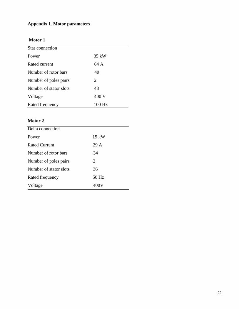
Appendix 1. Motor parameters
Motor 1
Star connection
Power 35 kW
Rated current 64 A
Number of rotor bars 40
Number of poles pairs 2
Number of stator slots 48
Voltage 400 V
Rated frequency 100 Hz
Motor 2
Delta connection
Power 15 kW
Rated Current 29 A
Number of rotor bars 34
Number of poles pairs 2
Number of stator slots 36
Rated frequency 50 Hz
Voltage 400V
23
Appendix 2. Matlab/Simulink model.
Appendix 3. Measurement setup
Voltage
Grid
Wide Band Power Analyzer Norma
Load resistor
Magnetizing current control
Inverter Vacon
Induction motor
DC generator
Current measurements
Isolator Sony A6907
Kontron WW700, Transient recorder. PC DOS
Current measurements
LEM