Embed Size (px)
Citation preview
Contents lists available at SciVerse ScienceDirect
Journal of Sound and Vibration
Journal of Sound and Vibration 332 (2013) 5981–5998
0022-46http://d
n CorrE-m
journal homepage: www.elsevier.com/locate/jsvi
Analytical solution for free vibrations of moderately thickhybrid piezoelectric laminated plates
M.A. Askari Farsangi a, A.R. Saidi a, R.C. Batra b,n
a Department of Mechanical Engineering, Shahid Bahonar University of Kerman, Kerman, Iranb Department of Engineering Science and Mechanics, Virginia Polytechnic Institute and State University, Blacksburg, VA 24061, USA
a r t i c l e i n f o
Article history:Received 2 January 2013Received in revised form13 May 2013Accepted 14 May 2013
Handling Editor: S. Ilankosatisfies Maxwell's equation and either open circuit or closed circuit boundary conditions
Available online 12 July 2013
0X/$ - see front matter & 2013 Elsevier Ltd.x.doi.org/10.1016/j.jsv.2013.05.010
esponding author. Tel.: +1 540 231 6051.ail address: [email protected] (R.C. Batra).
a b s t r a c t
An analytical solution for free vibrations of a hybrid rectangular plate composed ofa transversely isotropic, homogeneous and linear elastic core and face sheets made ofa linear piezoelectric material is derived by assuming that the plate deformations aregoverned by the Mindlin plate theory. The electric potential in a piezoelectric layer
on its major surfaces. For the hybrid plate coupled governing equations obtained from theHamilton principle are decoupled by introducing four auxiliary scalar functions, and theLevy type analytical solution for free vibrations is derived. Plate frequencies as a functionof the piezoelectric layer thickness and the plate aspect ratio are presented and discussed.It is found that the electric boundary conditions on major surfaces of the piezoelectriclayers and the aspect ratio of the hybrid plate noticeably influence its frequencies.Significant contributions of the work include proposing the four scalar functions touncouple the governing equations, providing an analytical solution for frequencies of thehybrid plate, and delineating effects of boundary conditions as well as of aspect ratio ofthe plate.
& 2013 Elsevier Ltd. All rights reserved.
1. Introduction
Piezoelectric materials have wide ranging applications. Their electromechanical coupling characteristics, which lead tomechanical deformations under an electric field and electrical polarization under mechanical loads, make them suitable fora variety of electromechanical devices used for data collection [1], cooling systems [2], vibration and noise suppression [3],energy harvesting [4], and telecommunication and sensor networks [5].
Static and dynamic deformations of a single-layer piezoelectric plate have been analyzed by Tiersten [6]. Wang and Yang[7] have reviewed the development of higher order theories for dynamic analysis of piezoelectric plates and classified themaccording to the variation in the thickness direction of displacements and the electric potential. Batra and Vidoli [8] haveproposed a Kth order shear and normal deformable theory for piezoelectric plates in which both the electric potential andthe three components of the mechanical displacement are expressed in terms of Legendre polynomials up to order K in thethickness coordinate. The governing equations have been derived by using a mixed variational principle and exactly satisfyelectromechanical boundary conditions on the top and the bottom surfaces of the plate. Shiyekar and Kant [45] have useda higher-order shear and normal deformable plate theory to analyze deformations of a hybrid functionally graded laminate
All rights reserved.
M.A. Askari Farsangi et al. / Journal of Sound and Vibration 332 (2013) 5981–59985982
with piezoelectric layers. Analytical results for free vibrations of piezoelectric plates are derived in Ref. [46], and theliterature on smart structures has been reviewed by Chopra [47].
Numerous studies have been carried out on free vibrations of piezoelectric coupled laminated plates. Tzou and Tseng [9]proposed an integrated distributed piezoelectric sensor/actuator design for a large distributed system (shells and plates) andstudied its dynamic characteristics. Heyliger et al. [10,24,25,35,36] have studied vibration problems for linear piezoelectricand linear magneto-electro-elastic laminates. Kapuria et al. [37,38] and Edery-Azulay and Abramovich [43] have proposedan extended Kantorvich method for analyzing vibrations of piezoelectric laminates and finding inter-laminar stresses.An exact three-dimensional (3D) analysis of simply supported piezoelectric coupled laminated plate was presented by Batraet al. [11] in which thin piezoelectric layers are modeled as membranes. Vel and Batra [39] have studied 3D free vibrations ofhybrid piezoelectric laminates, and Yang and Batra [48] of thermo-piezoelectric plates. Reddy [12] derived equations forlaminated composite plates with integrated sensors and actuators based on the classical and shear deformation platetheories. Vel et al. [13] extended the Stroh formalism to obtain an analytical solution for the steady state cylindrical bendingvibration of a composite plate with either surface mounted or embedded piezoelectric patches. The cylindrical bendingvibrations of a simply supported laminate with an embedded piezoelectric shear actuator have been investigated byBaillargeon and Vel [14]. Using the finite layer method, Akhras and Li [15] studied 3D deformations of simply supportedrectangular plates.
Topdar et al. [16] employed the finite element method (FEM) to study free vibrations of a piezoelectric coupled laminatedplate under various boundary conditions. Batra and Liang [40], and Batra and Geng [41] employed the FEM to delineate 3-Dfree and forced vibrations of hybrid piezoelectric laminates undergoing large or finite deformations.
The vibration analysis of simply supported hybrid piezoelectric laminated plates using the classical plate theory (CPT)and the first order shear deformation theory (FSDT or the Mindlin plate theory) was conducted by Pietrzakowski [17]. Freevibrations of simply supported orthotropic cross-ply laminates with piezoelectric layers bonded to the top and the bottomsurfaces have been studied by Torres and Mendonça [18], and Jin and Batra [19]. Whereas Torres and Mendonça assumedmechanical displacements based on a higher order shear deformation theory, Jin and Batra used the FSDT; in both studiesthe electric potential had layer wise discretization in the thickness direction.
For a simply supported laminated plate with embedded piezoelectric layers, Liang and Batra [20] investigated effects ofthickness, mass density and stiffness of the piezoelectric layer on plate's natural frequencies. The effect of electricalboundary conditions on major surfaces of piezoelectric layers was studied by Davis and Lesieutre [21]. Jin and Batra [19], andWu et al. [22] have shown that natural frequencies for the closed circuit and the open circuit conditions are quite different.Kapuria et al. [42] have recently reviewed the literature on piezoelectric composite laminates. Benjeddou [44] has providednew insights into vibrations of piezoelectric beams.
Many studies on free vibrations of hybrid plates having layers made of piezoelectric and non-piezoelectric materials arebased on the CPT [17,22]. As shown in [23] the CPT does not fully capture effects of the piezoelectric layer thickness onnatural frequencies of the coupled structure. Works using either the FSDT or a higher-order plate theory have numericallyanalyzed frequencies of hybrid plates. Here we present an analytical solution for free vibrations of a transversely isotropicplate with two identical (i.e., the same thickness and the same material) piezoelectric layers bonded to its top and thebottom surfaces. Two opposite edges of the plate are assumed to be simply supported but the other two edges can havedifferent boundary conditions. Similarly, the electric potential is taken to vanish at two opposite edges and the other twoedges can have either vanishing electric potential or overall null electric displacement. Equations governing free vibrationsof the plate are decoupled by introducing four auxiliary functions. The Levy type solution that identically satisfies boundaryconditions on simply supported edges is used to derive differential equations and boundary conditions for the four auxiliaryfunctions. Numerical results for natural frequencies of the hybrid plate are presented, and changes in frequencies of the coreplate due to the addition of piezoelectric layers are identified. Furthermore, effects of open circuit versus closed circuitboundary conditions on major surfaces of the two piezoelectric layers are delineated.
Significant contributions of the work include using the FSDT theory for the hybrid plate and quadratic variation of theelectric potential through the piezoelectric layer thickness, introducing four scalar functions to decouple the governingequations, analytically solving these equations, and delineating effects of closed and open circuit electric boundaryconditions on the hybrid plate frequencies.
2. Problem formulation
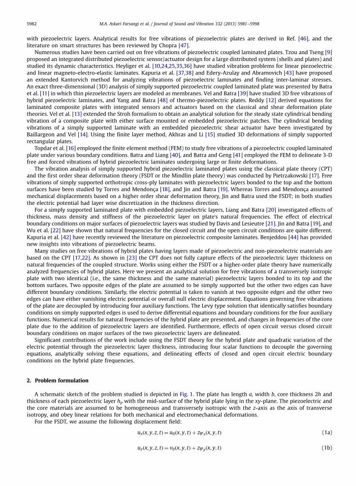
A schematic sketch of the problem studied is depicted in Fig. 1. The plate has length a, width b, core thickness 2h andthickness of each piezoelectric layer hp with the mid-surface of the hybrid plate lying in the xy-plane. The piezoelectric andthe core materials are assumed to be homogeneous and transversely isotropic with the z-axis as the axis of transverseisotropy, and obey linear relations for both mechanical and electromechanical deformations.
For the FSDT, we assume the following displacement field:
uxðx; y; z; tÞ ¼ u0ðx; y; tÞ þ zψxðx; y; tÞ (1a)
uyðx; y; z; tÞ ¼ v0ðx; y; tÞ þ zψyðx; y; tÞ (1b)
Fig. 1. Schematic sketch of the hybrid rectangular plate studied.
M.A. Askari Farsangi et al. / Journal of Sound and Vibration 332 (2013) 5981–5998 5983
uzðx; y; z; tÞ ¼wðx; y; tÞ (1c)
in which, u0, v0, and w are displacements along the x-, the y-, and the z-axis, respectively, of a point on the mid-surface, andψx and ψy represent rotations about the y- and the x-axis, respectively. The assumed displacement field (1) gives continuousdisplacements across interfaces between the piezoelectric layers and the core plate.
In rectangular Cartesian coordinates, the strain–displacement relation for infinitesimal deformations is
εg ¼ 12ð∇uþ ð∇uÞT Þ
n(2)
where ∇ is the gradient operator. The linear constitutive relations for the elastic core and the piezoelectric layers are takento be
frg ¼ ½C�fεg (3)
frg ¼ ½C′�fεg−½e�T fEg; fDg ¼ ½e�fεg þ ½Ξ�fEg (4)
where {E} and {D} are the electric field and the electrical displacement in the piezoelectric layer, respectively, [C] and ½C′�are, respectively, matrices of elastic constants for the core and the piezoelectric layer, ½Ξ� is the matrix of dielectricpermittivity, and ½e� is the electromechanical coupling matrix. These matrices, modified by solving the equation szz¼0 for εzzand substituting for εzz in Eqs. (3) and (4), are given as relations (A.1) in Appendix A. The electric potential Φ is related to theelectric field by
E¼−∇Φ (5)
Using Hamilton's principle, we get the following equations of motion [26]:
Nxx;x þ Nxy;y ¼ I0 €u0; Nxy;x þ Nyy;y ¼ I0 €v0; Qx;x þ Qy;y ¼ I0 €w (6a)
Mxx;x þMxy;y−Qx ¼ I2 €ψx; Mxy;x þMyy;y−Qy ¼ I2 €ψy (6b)
In Eqs. (6a) and (6b) a superimposed dot denotes differentiation with respect to time t, and the in-plane resultant forcesðNxx;Nxy;NyyÞ, resultant moments ðMxx;Mxy;MyyÞ, the resultant transverse forces ðQx;QyÞ, and the mass moments of inertiaðI0; I2Þ are defined below:
ðNxx;Nxy;NyyÞ ¼Z hþhp
−h−hpðsxx; sxy; syyÞdz; ðQx;QyÞ ¼
Z hþhp
−h−hpðsxz; syzÞdz
ðMxx;Mxy;MyyÞ ¼Z hþhp
−h−hpðsxx; sxy; syyÞzdz; ðIo; I2Þ ¼
Z hþhp
−h−hpρð1; z2Þdz (7)
We neglect inertia effects for the electrical problem since time scales for it are much smaller than those for themechanical problem. The continuity of surface tractions at the interfaces between the piezoelectric layers and the core platehas been tacitly assumed in deriving Eqs. (6). Analogous to Eqs. (6) for the mechanical equilibrium, we satisfy the Maxwellequation in the following integral form:
Z hþhp
h∇ � D dzþ
Z −h
−h−hp∇ � D dz¼
Z hþhp
hðDx;x þ Dy;y þ Dz;zÞdzþ
Z −h
−h−hpðDx;x þ Dy;y þ Dz;zÞdz¼ 0 (8)
The top and the bottom surfaces of the hybrid laminate are traction free. We consider one of the following two electricalboundary conditions on major surfaces of the piezoelectric layers.
Φðz¼ 7hÞ ¼ 0; Φðz¼ 7 ðhþ hpÞÞ ¼ 0; (9a)
M.A. Askari Farsangi et al. / Journal of Sound and Vibration 332 (2013) 5981–59985984
Φðz¼ 7hÞ ¼ 0; Dzðz¼ 7ðhþ hpÞÞ ¼ 0 (9b)
That is, in each case the interface between the piezoelectric layer and the core plate is at zero potential, and theoutermost surfaces of the piezoelectric layer are either held at zero potential or are electrically insulated. The edges x¼ 0and x¼ a are assumed to be at zero potential, and on the other two edges y¼ −b=2 and y¼ b=2 either the electric potentialis prescribed to be zero or they are electrically insulated in which case the following boundary condition holds:
Z hþhp
hDy x; 7
b2; z; t
� �dzþ
Z −h
−h−hpDy x; 7
b2; z; t
� �dz¼ 0 (10)
We consider the following mechanical boundary conditions on edges y¼−b=2 and y¼ b=2:
(i)
Clamped:u0 ¼ v0 ¼w¼ ψx ¼ ψy ¼ 0 (11a)
(ii)
Free:Nxy ¼Nyy ¼ Qy ¼Mxy ¼Myy ¼ 0 (11b)
(iii)
Simply supported:Nxy ¼Nyy ¼w¼Mxy ¼Myy ¼ 0 (11c)
The other two edges, x¼ 0 and x¼ a, are assumed to be simply supported with boundary conditions analogous toEq. (11c) applied on them. Free, clamped and simply supported edges are denoted by F, C and S, respectively.
3. Analytical solution
3.1. Electric problem
When the two major surfaces of the piezoelectric layer are held at zero voltage (i.e., closed circuit or boundary conditions(9a) prescribed on them), we assume the following quadratic variation of Φ in the transverse coordinate, z [27]:
Φðx; y; z; tÞ ¼φðx; y; tÞ 1− z−h−hp=2
hp=2
� �2� �
; h≤z≤hþ hp
φðx; y; tÞ 1− −z−h−hp=2hp=2
� �2� �
; −h−hp≤z≤−h
8>>><>>>:
(12a)
However, when one surface is kept at zero voltage and the other is electrically insulated (i.e., open circuit or boundaryconditions (9b) prescribed on them), we postulate that
Φðx; y; z; tÞ ¼
ϕðx; y; tÞ 1− z−h−hp=2hp=2
� �2þ 4ðz−hÞ
hp
� �
þ e31Ξ33
u;x þ v;y þ ðhþ hpÞðψx;x þ ψy;yÞ� ðz−hÞ h≤z≤hþ hp
ϕðx; y; tÞ 1− −z−h−hp=2hp=2
� �2þ −4ðzþhÞ
hp
� �
þ e31Ξ33
u;x þ v;y−ðhþ hpÞðψx;x þ ψy;yÞ� ðzþ hÞ −h−hp≤z≤−h
8>>>>>>>>>><>>>>>>>>>>:
(12b)
with expressions for e31 and Ξ33 given in Appendix A.Substitution from Eq. (12) into Eq. (5) and the result into Eqs. (4) and (8) gives the following equation for the
determination of the function ϕ appearing in Eq. (12).
μ4ðw;xx þw;yyÞ−μ2ðψx;xxx þ ψx;xyy þ ψy;yxx þ ψy;yyyÞ−μ3ðϕ;xx þ ϕ;yyÞ þ μ5ðψx;x þ ψy;yÞ þ μ6ϕ¼ 0 (13)
Boundary conditions for ϕ are
ϕða; y; tÞ ¼ ϕð0; y; tÞ ¼ 0; andeither ϕ x; b2 ; t
�¼ ϕ x;− b2 ; t
�¼ 0
orR hþhph Dy x; 7 b
2 ; z; t �
dzþ R −h−h−hp Dy x; 7 b
2 ; z; t �
dz¼ 0(14)
Eq. (13) exhibits coupling between electrical and mechanical effects. For the open and the closed circuit conditions,material moduli μ2; :::; μ6 listed in Appendix A have different values.
M.A. Askari Farsangi et al. / Journal of Sound and Vibration 332 (2013) 5981–5998 5985
3.2. Mechanical problem
Upon substitution of relations (1), (2), (3) and (4) into (7), resultant forces and resultant moments are expressed in termsof the generalized displacements and the electric potential ϕ as
Nxx ¼ A′11u0;x þ A′
12v0;y; Nyy ¼ A′12u0;x þ A′
11v0;y; Nxy ¼ A′66ðu0;y þ v0;xÞ (15a,b,c)
Mxx ¼D′11ψx;x þ D′
12ψy;y þ μ1ϕ; Myy ¼D′12ψx;x þ D′
11ψy;y þ μ1ϕ; Mxy ¼D′66ðψx;y þ ψy;xÞ (15d,e,f)
Qx ¼ K2A′55ðw;x þ ψxÞ−μ2ðψx;xx þ ψy;xyÞ−μ3ϕ;x (15g)
Qy ¼ K2A′55ðw;y þ ψyÞ−μ2ðψx;xy þ ψy;yyÞ−μ3ϕ;y (15h)
where K2 is the shear correction factor which is assumed to be π2=12. Expressions for coefficients in relations (15a–h) aregiven as Eq. (A.2) of Appendix A.
Substitution from relations (15) into Eqs. (6) gives following equations for the displacements:
A′11u0;xx þ A′
12v0;xy þ A′12ðu0;xx þ v0;xyÞ ¼ I0 €u0; A
′12u0;xy þ A′
11v0;yy þ A′66ðu0;xy þ v0;xxÞ ¼ I0 €v0 (16a,b)
D′11ψx;xx þ D′
12ψy;xy þ D′66ðψx;yy þ ψy;xyÞ þ μ2ðψx;xx þ ψy;xyÞ−K2A′
55ðw;x þ ψxÞ þ ðμ1 þ μ3Þϕ;x ¼ I2 €ψx (16c)
D′12ψx;xy þ D′
11ψy;yy þ D′66ðψx;xy þ ψy;xxÞ þ μ2ðψx;xy þ ψy;yyÞ−K2A′
55ðw;y þ ψyÞ þ ðμ1 þ μ3Þϕ;y ¼ I2 €ψy (16d)
K2A′55ðw;xx þw;yy þ ψx;x þ ψy;yÞ−μ2ðψx;xxx þ ψx;xyy þ ψy;yxx þ ψy;yyyÞ−μ3ðϕ;xx þ ϕ;yyÞ ¼ I0 €w (16e)
Eqs. (16a) and (16b) govern stretching (u0 and v0) of the plate midsurface, Eqs. (16c)–(16e) its bending (w, ψx, ψy), andthere is no coupling between the two types of deformations. However, Eqs. (16a) and (16b) are coupled, and so are Eqs. (16c)–(16e) and (13). We simplify these equations as follows.
We introduce four auxiliary functions φ1; φ2; φ3 and φ4 defined by
φ1
φ2
φ3
φ4
8>>>><>>>>:
9>>>>=>>>>;
¼
u0;x þ v0;yu0;y−v0;xψx;x þ ψy;y
ψx;y−ψy;x
8>>>><>>>>:
9>>>>=>>>>;
(17)
and rewrite Eqs. (16) and (13) as
A′11φ1;x þ A′66φ2;y ¼ I0 €u0; A′11φ1;y−A′66φ2;x ¼ I0 €v0 (18a,b)
D′11φ3;x þ D′
66φ4;y−K2A′
55ðw;x þ ψxÞ þ μ2φ3;x þ ðμ1 þ μ3Þϕ;x ¼ I2 €ψx (18c)
D′11φ3;y−D
′66φ4;x−K
2A′55ðw;y þ ψyÞ þ μ2φ3;y þ ðμ1 þ μ3Þϕ;y ¼ I2 €ψy (18d)
K2A′55ð∇2wþ φ3Þ−μ2∇2φ3−μ3∇
2ϕ¼ I0 €w; μ4∇2w−μ2∇
2φ3−μ3∇2ϕþ μ5φ3 þ μ6ϕ¼ 0 (18e,f)
where ∇2is the 2D Laplace operator in the xy-plane. Differentiation of Eqs. (18a) and (18c) with respect to x and of Eqs. (18b)and (18d) with respect to y, and adding Eq. (18a) to Eq. (18b) and Eq. (18c) to Eq. (18d) give
A′11∇
2φ1 ¼ I0 €ϕ1; D′11∇
2φ3−K2A′
55ð∇2wþ φ3Þ þ μ2∇2φ3 þ ðμ1 þ μ3Þ∇2ϕ¼ I2 €φ3 (19a,b)
Differentiation of Eqs. (18a) and (18c) with respect to y and of Eqs. (18b) and (18d) with respect to x, and subtractingEq. (18a) from Eq. (18b) and Eq. (18c) from Eq. (18d) give
A′66∇
2φ2 ¼ I0 €φ2; D′66∇
2φ4−K2A′
55φ4 ¼ I2 €φ4 (20a,b)
It can be seen that Eqs. (18a) through (18d) are replaced by four Eqs. (19) and (20). Whereas Eqs. (19a), (20a) and (20b)are uncoupled, Eqs. (19b), (18e) and (18f) are coupled. These six equations are solved for the six unknown functions ϕ, φ1,φ2, φ3, φ4 and w.
For harmonic motion the six unknowns ϕ, φ1, φ2, φ3, φ4 and w are assumed to have the following form:
wðx; y; tÞ ¼ ∑∞
m ¼ 1wmðx; yÞeiωmt ; ϕðx; y; tÞ ¼ ∑
∞
m ¼ 1ϕmðx; yÞeiωmt
φ1ðx; y; tÞ ¼ ∑∞
m ¼ 1φ1mðx; yÞeiωmt ; φ2ðx; y; tÞ ¼ ∑
∞
m ¼ 1φ2mðx; yÞeiωmt

M.A. Askari Farsangi et al. / Journal of Sound and Vibration 332 (2013) 5981–59985986
φ3ðx; y; tÞ ¼ ∑∞
m ¼ 1φ3mðx; yÞeiωmt ; φ4ðx; y; tÞ ¼ ∑
∞
m ¼ 1φ4mðx; yÞeiωmt (21)
where ωm is a natural frequency of the plate.Substituting from Eq. (21) into Eq. (18e,f) and (19b) and after algebraic manipulations we obtain the following three
uncoupled differential equations with constant coefficients:
λ1∇6wm þ λ2∇4wm þ λ3∇2wm þ λ4wm ¼ 0; φ3m ¼ λ′1∇4wm þ λ′2∇
2wm þ λ′3wm; (22a,b)
ϕm ¼ λ″1∇2wm þ λ″3wm þ λ″3φ3m (22c)
Coefficients λiði¼ 1; :::;4Þ and λ′k; λ″kðk¼ 1;2;3Þ with values depending upon hp and h are given as relations (A.3) in
Appendix A. They couple electrical and mechanical effects. Furthermore, substitution from Eq. (21) into Eqs. (19a) and (20)yields
A′11∇
2φ1m ¼ −I0ω2φ1m; A′66∇
2φ2m ¼−I0ω2φ2m; D′66∇
2φ4m−K2A′
55φ4m ¼−I2ω2φ4m (23a,b,c)
Eqs. (22) and (23) are coupled because coefficients are functions of the frequency ω.For a harmonic motion, displacements u0, v0, ψx and ψy are written as
u0ðx; y; tÞ ¼ ∑∞
m ¼ 1u0mðx; yÞ eiωmt ; v0ðx; y; tÞ ¼ ∑
∞
m ¼ 1v0mðx; yÞ eiωmt
ψxðx; y; tÞ ¼ ∑∞
m ¼ 1ψxmðx; yÞ eiωmt ; ψyðx; y; tÞ ¼ ∑
∞
m ¼ 1ψymðx; yÞ eiωmt (24)
Substituting from Eqs. (21) and (24) into Eqs. (18a)–(18d), we get
u0m ¼ −1
I0ω2 ðA′11φ1m;x þ A′
66φ2m;yÞ; v0m ¼−1
I0ω2 ðA′11φ1m;y−A
′66φ2m;xÞ (25a,b)
ψxm ¼−1
I2ω2 D′11φ3m;x þ D′
66φ4m;y−K2A′
55ðwm;x þ ψxmÞ þ μ2φ3m;x þ ðμ1 þ μ3Þϕm;x
h i(25c)
ψym ¼ −1
I2ω2 D′11φ3m;y−D
′66φ4m;x−K
2A′55ðwm;y þ ψymÞ þ μ2φ3m;y þ ðμ1 þ μ3Þϕm;y
h i(25d)
Thus generalized displacements and the electric potential can be found once we know ϕ, φ1, φ2, φ3, φ4 and w.
3.3. Analytical solution
Recalling that edges x¼ 0 and x¼ a are simply supported, we assume the following expressions for the transversedisplacement wm and functions φ1m; φ2m and φ4m:
wmðx; yÞ ¼ ∑∞
j ¼ 1wmjðyÞ sin ðβjxÞ; φ1mðx; yÞ ¼ ∑
∞
j ¼ 1φ1mjðyÞ sin ðβjxÞ (26a,b)
φ2mðx; yÞ ¼ ∑∞
j ¼ 1φ2mjðyÞ cos ðβjxÞ; φ4mðx; yÞ ¼ ∑
∞
j ¼ 1φ4mjðyÞ cos ðβjxÞ (26c,d)
where βj ¼ jπ=a. Substitution from Eqs. (26) into Eqs. (22a) and (23) results in four ordinary differential equations whosesolutions are [29]
wmjðyÞ ¼ C1sinhðη1yÞ þ C2coshðη1yÞ þ C3sinhðη2yÞ þ C4coshðη2yÞ þ C5sinhðη3yÞ þ C6coshðη3yÞ (27a)
φ1mjðyÞ ¼ C7sinhðη4yÞ þ C8coshðη4yÞ (27b)
φ2mjðyÞ ¼ C9sinhðη5yÞ þ C10coshðη5yÞ (27c)
φ4mjðyÞ ¼ C11sinhðη6yÞ þ C12coshðη6yÞ (27d)
in which Ckðk¼ 1; :::;12Þ are twelve unknown constants to be determined from twelve boundary conditions, six (5 listed inEq. (11) and 1 for ϕ) at each edge, y¼ 7b=2. Substitution from Eq. (27a) into Eq. (22a), we find that parametersηk ¼
ffiffiffiffiffiεk
p ðk¼ 1;2;3Þ are roots of the following cubic equation:
λ1ε3 þ ðλ2−3βj2λ1Þε2 þ ðλ3−2λ2βj2 þ 3λ1βj
4Þεþ ðλ4−λ3βj2 þ λ2βj4−λ1βj6Þ ¼ 0 (28)
Values of parameters η4; η5 and η6 are obtained from relations (A.4) of Appendix A. Note that solutions (27) are valid forreal values of ηk. For imaginary values of ηk, sinh and cosh become sin and cos, respectively. After having found w we get φ3m
from Eq. (22b) and then ϕ from Eq. (22c). Eq (25) can now be used to ascertain the generalized displacements.
M.A. Askari Farsangi et al. / Journal of Sound and Vibration 332 (2013) 5981–5998 5987
By imposing electrical and mechanical boundary conditions on edges y¼−b=2 and y¼ b=2, a system of twelvehomogeneous linear algebraic equations is obtained. Setting the determinant of the coefficient matrix equal to zero, weobtain an algebraic equation for the determination of natural frequencies of the hybrid plate.
4. Numerical results and discussion
Unless otherwise mentioned, numerical results for free vibrations of a hybrid rectangular plate with core made of Al2O3
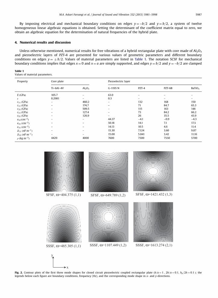
and piezoelectric layers of PZT-4 are presented for various values of geometric parameters and different boundaryconditions on edges y¼ 7b=2. Values of material parameters are listed in Table 1. The notation SCSF for mechanicalboundary conditions implies that edges x¼ 0 and x¼ a are simply supported, and edges y¼ b=2 and y¼ −b=2 are clamped
Table 1Values of material parameters.
Property Core plate Piezoelectric layer
Ti–6Al–4V Al2O3 G-1195 N PZT-4 PZT-6B BaTiO3
E ðGPaÞ 105.7 – 63.0 – – –
ν 0.2981 – 0.3 – – –
c11 ðGPaÞ – 460.2 – 132 168 150c12 ðGPaÞ – 174.7 – 71 84.7 65.3c33 ðGPaÞ – 509.5 – 115 163 146c13 ðGPaÞ – 127.4 – 73 84.2 66.2c55 ðGPaÞ – 126.9 – 26 35.5 43.9e31ðcm−2Þ – – 44.37 −4.1 −0.9 −4.3e33 ðcm−2Þ – – 50.18 14.1 7.1 17.5
e15 ðcm−2Þ – – 14.13 10.5 4.6 11.4
Ξ11 ðnF m−1Þ – – 15.30 7.124 3.60 9.87
Ξ33 ðnF m−1Þ – – 15.00 5.841 3.42 11.16
ρ ðkg m−3Þ 4429 4000 7600 7500 7550 5700
Fig. 2. Contour plots of the first three mode shapes for closed circuit piezoelectric coupled rectangular plate ðb=a¼ 1 ; 2h=a¼ 0:1; hp=2h¼ 0:1 Þ; thelegends below each figure are boundary conditions, frequency (Hz), and the corresponding mode shape in x- and y-directions.
M.A. Askari Farsangi et al. / Journal of Sound and Vibration 332 (2013) 5981–59985988
and free, respectively. Also, numbers in parenthesis following the value of the natural frequency equal the mode numbersalong the x and the y directions, respectively. Contour plots of the first three mode shapes are exhibited in Fig. 2 for a hybridpiezoelectric rectangular plate under different mechanical boundary conditions.
4.1. Comparison of presently computed results with those in the literature
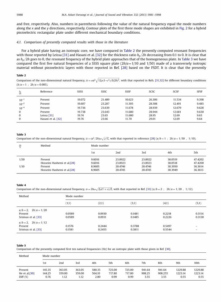
For a hybrid plate having an isotropic core, we have compared in Table 2 the presently computed resonant frequencieswith those reported by Leissa [31] and Hasani et al. [32] for the thickness ratio hp=2h decreasing from 0.1 to 0. It is clear thatas hp=2h goes to 0, the resonant frequency of the hybrid plate approaches that of the homogeneous plate. In Table 3 we havecompared the first five natural frequencies of a SSSS square plate (2h/a¼1/10 and 1/50) made of a transversely isotropicmaterial without piezoelectric layers with those reported in Ref. [28] based on the FSDT. It is clear that the presently
Table 2
Comparison of the non-dimensional natural frequency, ω¼ωa2ffiffiffiffiffiffiffiffiffiffiffiffiffiffiffiffiffiffiffiffiffiffiffiffiffiffiffiffiffiffiffiffiffiffiffiffiffiffi12ρð1−ν2Þ=Eð2hÞ2
q, with that reported in Refs. [31,32] for different boundary conditions
(b=a¼ 1 ; 2h=a¼ 0:005).
hp2h
Reference SSSS SSSC SSSF SCSC SCSF SFSF
10−1 Present 19.072 21.489 10.623 26.306 11.534 9.398
10−2 Present 19.607 23.287 11.505 28.508 12.491 9.485
10−4 Present 19.736 23.639 11.678 28.939 12.679 9.628
0 Present 19.738 23.643 11.680 28.944 12.681 9.6300 Leissa [31] 19.74 23.65 11.680 28.95 12.69 9.630 Hasani et al. [32] 19.76 23.66 11.70 29.01 12.69 9.64
Table 3Comparison of the non-dimensional natural frequency, ω¼ ða2=2hÞω
ffiffiffiffiffiffiffiffiρ=G
p, with that reported in reference [28] (a=b¼ 1 ; 2h=a¼ 1=50 ; 1=10).
2ha
Method Mode number
1st 2nd 3rd 4th 5th
1/50 Present 9.6016 23.8922 23.8922 38.0519 47.4202Hosseini Hashemi et al.[28] 9.6016 23.8923 23.8923 38.0518 47.4200
1/10 Present 8.9605 20.4746 20.4746 30.3950 36.3614Hosseini Hashemi et al.[28] 8.9605 20.4745 20.4745 30.3949 36.3613
Table 4Comparison of the non-dimensional natural frequency, ω¼ 2hω
ffiffiffiffiffiffiffiffiffiffiffiffiffiffiffiffiffiffiffiffiffiffiffiffiffi2ρð1þ νÞ=E
p, with that reported in Ref. [33] (a=b¼ 2 ; 2h=a¼ 1=20 ; 1=12).
Method Mode number
(1,1) (2,1) (3,1) (4,1) (5,1)
a=b¼ 2; 2h=a¼ 1=20Present 0.0589 0.0930 0.1481 0.2218 0.3114Srinivas et al. [33] 0.0589 0.0931 0.1485 0.2226 0.3130
a=b¼ 2; 2h=a¼ 1=12Present 0.1576 0.2444 0.3788 0.5497 –
Srinivas et al. [33] 0.1581 0.2455 0.3811 0.5544 –
Table 5Comparison of the presently computed first ten natural frequencies (Hz) for an isotropic plate with those given in Ref. [30].
Method Mode number
1st 2nd 3rd 4th 5th 6th 7th 8th 9th 10th
Present 145.35 363.05 363.05 580.35 725.00 725.00 941.64 941.64 1229.88 1229.88He et al.[30] 144.25 359.00 359.00 564.10 717.80 717.80 908.25 908.255 1223.14 1223.14Diff (%) 0.76 1.12 1.12 2.80 0.99 0.99 3.55 3.55 0.55 0.55
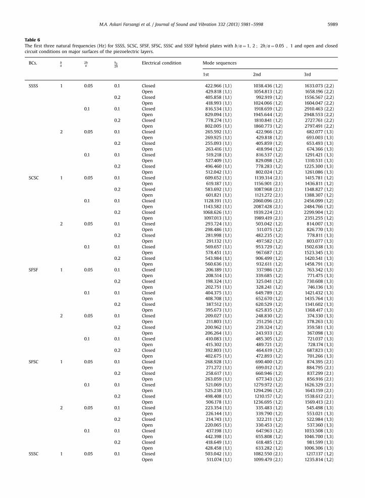
Table 6The first three natural frequencies (Hz) for SSSS, SCSC, SFSF, SFSC, SSSC and SSSF hybrid plates with b=a¼ 1; 2 ; 2h=a¼ 0:05 ; 1 and open and closedcircuit conditions on major surfaces of the piezoelectric layers.
BCs. ba
2ha
hp2h
Electrical condition Mode sequences
1st 2nd 3rd
SSSS 1 0.05 0.1 Closed 422.966 (1,1) 1038.436 (1,2) 1633.073 (2,2)Open 429.818 (1,1) 1054.813 (1,2) 1658.196 (2,2)
0.2 Closed 405.858 (1,1) 992.919 (1,2) 1556.567 (2,2)Open 418.993 (1,1) 1024.066 (1,2) 1604.047 (2,2)
0.1 0.1 Closed 816.534 (1,1) 1918.659 (1,2) 2910.463 (2,2)Open 829.094 (1,1) 1945.644 (1,2) 2948.553 (2,2)
0.2 Closed 778.274 (1,1) 1810.841 (1,2) 2727.761 (2,2)Open 802.005 (1,1) 1860.773 (1,2) 2797.491 (2,2)
2 0.05 0.1 Closed 265.592 (1,1) 422.966 (1,2) 682.077 (1,3)Open 269.925 (1,1) 429.818 (1,2) 693.003 (1,3)
0.2 Closed 255.093 (1,1) 405.859 (1,2) 653.493 (1,3)Open 263.416 (1,1) 418.994 (1,2) 674.366 (1,3)
0.1 0.1 Closed 519.218 (1,1) 816.537 (1,2) 1291.421 (1,3)Open 527.409 (1,1) 829.098 (1,2) 1310.531 (1,3)
0.2 Closed 496.460 (1,1) 778.283 (1,2) 1225.300 (1,3)Open 512.042 (1,1) 802.024 (1,2) 1261.086 (1,3)
SCSC 1 0.05 0.1 Closed 609.652 (1,1) 1139.314 (2,1) 1415.781 (1,2)Open 619.187 (1,1) 1156.901 (2,1) 1436.811 (1,2)
0.2 Closed 583.692 (1,1) 1087.968 (2,1) 1348.827 (1,2)Open 601.821 (1,1) 1121.272 (2,1) 1388.307 (1,2)
0.1 0.1 Closed 1128.191 (1,1) 2060.096 (2,1) 2456.099 (1,2)Open 1143.582 (1,1) 2087.428 (2,1) 2484.766 (1,2)
0.2 Closed 1068.626 (1,1) 1939.224 (2,1) 2299.904 (1,2)Open 1097.013 (1,1) 1989.419 (2,1) 2351.255 (1,2)
2 0.05 0.1 Closed 293.724 (1,1) 503.042 (1,2) 814.007 (1,3)Open 298.486 (1,1) 511.075 (1,2) 826.770 (1,3)
0.2 Closed 281.998 (1,1) 482.235 (1,2) 778.811 (1,3)Open 291.132 (1,1) 497.582 (1,2) 803.077 (1,3)
0.1 0.1 Closed 569.657 (1,1) 953.729 (1,2) 1502.638 (1,3)Open 578.451 (1,1) 967.687 (1,2) 1523.345 (1,3)
0.2 Closed 543.984 (1,1) 906.499 (1,2) 1420.541 (1,3)Open 560.636 (1,1) 932.611 (1,2) 1458.791 (1,3)
SFSF 1 0.05 0.1 Closed 206.189 (1,1) 337.986 (1,2) 763.342 (1,3)Open 208.514 (1,1) 339.685 (1,2) 771.475 (1,3)
0.2 Closed 198.324 (1,1) 325.041 (1,2) 730.608 (1,3)Open 202.751 (1,1) 328.241 (1,2) 746.136 (1,3)
0.1 0.1 Closed 404.375 (1,1) 649.789 (1,2) 1421.432 (1,3)Open 408.708 (1,1) 652.670 (1,2) 1435.764 (1,3)
0.2 Closed 387.512 (1,1) 620.529 (1,2) 1341.602 (1,3)Open 395.673 (1,1) 625.835 (1,2) 1368.417 (1,3)
2 0.05 0.1 Closed 209.027 (1,1) 248.830 (1,2) 374.330 (1,3)Open 211.803 (1,1) 251.256 (1,2) 378.263 (1,3)
0.2 Closed 200.962 (1,1) 239.324 (1,2) 359.581 (1,3)Open 206.264 (1,1) 243.933 (1,2) 367.098 (1,3)
0.1 0.1 Closed 410.083 (1,1) 485.305 (1,2) 721.037 (1,3)Open 415.302 (1,1) 489.721 (1,2) 728.174 (1,3)
0.2 Closed 392.803 (1,1) 464.619 (1,2) 687.823 (1,3)Open 402.675 (1,1) 472.893 (1,2) 701.266 (1,3)
SFSC 1 0.05 0.1 Closed 268.928 (1,1) 690.400 (1,2) 874.395 (2,1)Open 271.272 (1,1) 699.012 (1,2) 884.795 (2,1)
0.2 Closed 258.617 (1,1) 660.946 (1,2) 837.299 (2,1)Open 263.059 (1,1) 677.343 (1,2) 856.916 (2,1)
0.1 0.1 Closed 521.069 (1,1) 1279.972 (1,2) 1626.329 (2,1)Open 525.238 (1,1) 1294.296 (1,2) 1643.159 (2,1)
0.2 Closed 498.408 (1,1) 1210.157 (1,2) 1538.612 (2,1)Open 506.178 (1,1) 1236.695 (1,2) 1569.413 (2,1)
2 0.05 0.1 Closed 223.354 (1,1) 335.483 (1,2) 545.498 (1,3)Open 226.144 (1,1) 339.790 (1,2) 553.021 (1,3)
0.2 Closed 214.743 (1,1) 322.211 (1,2) 522.984 (1,3)Open 220.065 (1,1) 330.453 (1,2) 537.360 (1,3)
0.1 0.1 Closed 437.198 (1,1) 647.963 (1,2) 1033.508 (1,3)Open 442.398 (1,1) 655.808 (1,2) 1046.700 (1,3)
0.2 Closed 418.649 (1,1) 618.485 (1,2) 981.599 (1,3)Open 428.458 (1,1) 633.282 (1,2) 1006.306 (1,3)
SSSC 1 0.05 0.1 Closed 503.042 (1,1) 1082.550 (2,1) 1217.137 (1,2)Open 511.074 (1,1) 1099.479 (2,1) 1235.814 (1,2)
M.A. Askari Farsangi et al. / Journal of Sound and Vibration 332 (2013) 5981–5998 5989
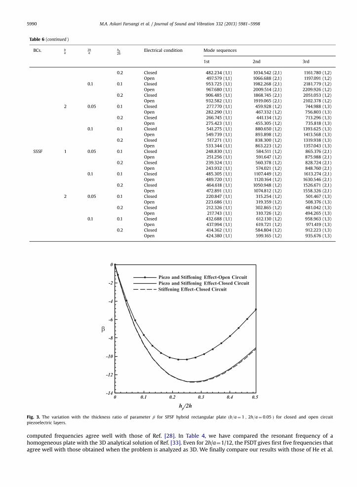
Table 6 (continued )
BCs. ba
2ha
hp2h
Electrical condition Mode sequences
1st 2nd 3rd
0.2 Closed 482.234 (1,1) 1034.542 (2,1) 1161.780 (1,2)Open 497.579 (1,1) 1066.688 (2,1) 1197.091 (1,2)
0.1 0.1 Closed 953.725 (1,1) 1982.268 (2,1) 2181.779 (1,2)Open 967.680 (1,1) 2009.514 (2,1) 2209.926 (1,2)
0.2 Closed 906.485 (1,1) 1868.745 (2,1) 2051.053 (1,2)Open 932.582 (1,1) 1919.065 (2,1) 2102.378 (1,2)
2 0.05 0.1 Closed 277.770 (1,1) 459.928 (1,2) 744.988 (1,3)Open 282.290 (1,1) 467.332 (1,2) 756.803 (1,3)
0.2 Closed 266.745 (1,1) 441.134 (1,2) 713.296 (1,3)Open 275.423 (1,1) 455.305 (1,2) 735.818 (1,3)
0.1 0.1 Closed 541.275 (1,1) 880.650 (1,2) 1393.625 (1,3)Open 549.739 (1,1) 893.898 (1,2) 1413.568 (1,3)
0.2 Closed 517.271 (1,1) 838.300 (1,2) 1319.938 (1,3)Open 533.344 (1,1) 863.223 (1,2) 1357.043 (1,3)
SSSF 1 0.05 0.1 Closed 248.830 (1,1) 584.511 (1,2) 865.376 (2,1)Open 251.256 (1,1) 591.647 (1,2) 875.988 (2,1)
0.2 Closed 239.324 (1,1) 560.378 (1,2) 828.724 (2,1)Open 243.932 (1,1) 574.021 (1,2) 848.760 (2,1)
0.1 0.1 Closed 485.305 (1,1) 1107.449 (1,2) 1613.274 (2,1)Open 489.720 (1,1) 1120.164 (1,2) 1630.546 (2,1)
0.2 Closed 464.618 (1,1) 1050.948 (1,2) 1526.671 (2,1)Open 472.891 (1,1) 1074.812 (1,2) 1558.326 (2,1)
2 0.05 0.1 Closed 220.847 (1,1) 315.254 (1,2) 501.467 (1,3)Open 223.686 (1,1) 319.359 (1,2) 508.376 (1,3)
0.2 Closed 212.326 (1,1) 302.865 (1,2) 481.042 (1,3)Open 217.743 (1,1) 310.726 (1,2) 494.265 (1,3)
0.1 0.1 Closed 432.688 (1,1) 612.130 (1,2) 958.963 (1,3)Open 437.994 (1,1) 619.721 (1,2) 971.419 (1,3)
0.2 Closed 414.362 (1,1) 584.804 (1,2) 912.223 (1,3)Open 424.380 (1,1) 599.165 (1,2) 935.676 (1,3)
Fig. 3. The variation with the thickness ratio of parameter β for SFSF hybrid rectangular plate ðb=a¼ 1 ; 2h=a¼ 0:05 Þ for closed and open circuitpiezoelectric layers.
M.A. Askari Farsangi et al. / Journal of Sound and Vibration 332 (2013) 5981–59985990
computed frequencies agree well with those of Ref. [28]. In Table 4, we have compared the resonant frequency of ahomogeneous plate with the 3D analytical solution of Ref. [33]. Even for 2h/a¼1/12, the FSDT gives first five frequencies thatagree well with those obtained when the problem is analyzed as 3D. We finally compare our results with those of He et al.
M.A. Askari Farsangi et al. / Journal of Sound and Vibration 332 (2013) 5981–5998 5991
[30] who used the CLPT and the FEM to compute frequencies of a plate. Table 5 lists the first ten natural frequencies of asquare isotropic plate with Ti–6Al–4V core, the top and the bottom G-1195 N piezoelectric layers, a¼b¼40 cm, h¼5 mm,and hp¼0.1 mm. It can be seen from values listed in Table 5 that frequencies predicted by the CLPT are a little lower (by atmost 3.5%) instead of being a little higher than those given by the FSDT. It is possible that the FE mesh used in [30] did notgive fully converged values of the frequencies.
4.2. Frequencies of hybrid plates
We have listed in Table 6 the first three natural frequencies of hybrid plates of aspect ratio, b=a; equal to 1 and 2,thickness-length ratio ð2h=aÞ¼0.05 and 0.1, and hp=2h¼ 0:1 and 0.2, open and closed circuit piezoelectric layers, andsymmetric and asymmetric mechanical boundary conditions. These results imply that with the doubling of the plate widthb, the natural frequency decreases for all types of mechanical boundary conditions except SFSF, and for both closed and opencircuit electrical boundary conditions on major surfaces of the plate. Also doubling the value of 2h=a enhances the naturalfrequency. For fixed electrical boundary conditions, natural frequencies monotonically increase as mechanical boundaryconditions on edges y¼b/2 and y¼−b/2 are changed in the following sequence: SFSF, SSSF, SFSC, SSSS, SSSC and SCSC. Ofcourse, mode shapes depend upon the boundary conditions.
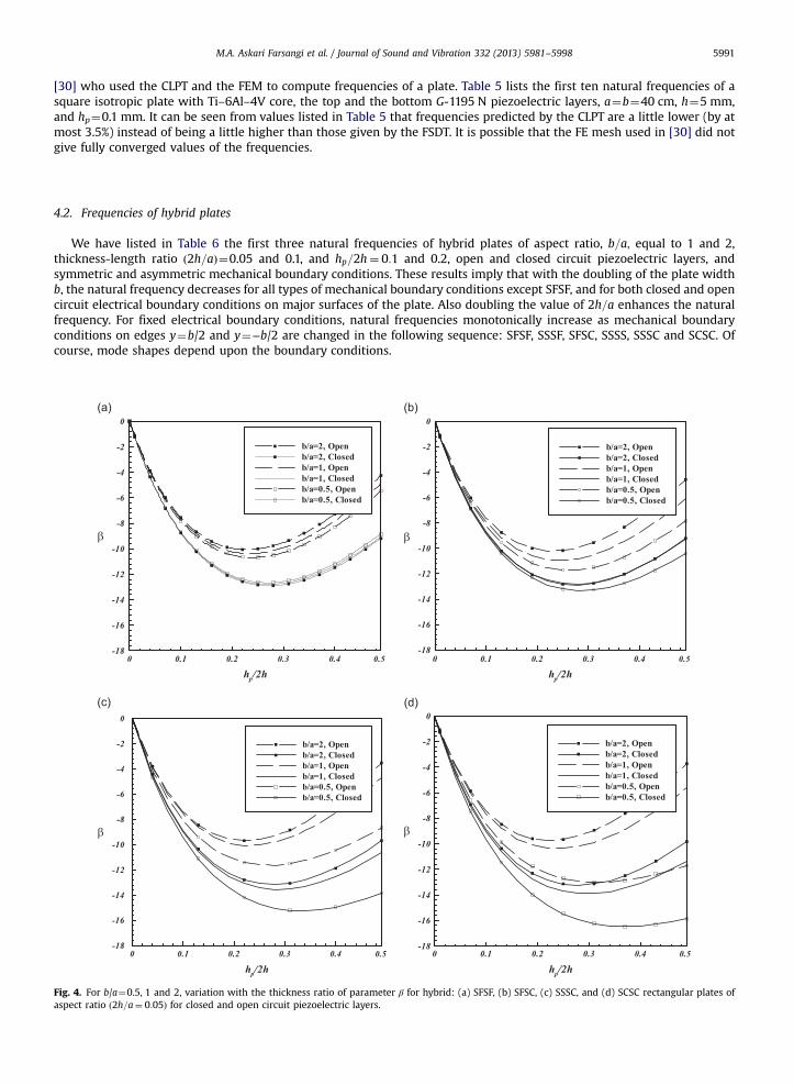
Fig. 4. For b/a¼0.5, 1 and 2, variation with the thickness ratio of parameter β for hybrid: (a) SFSF, (b) SFSC, (c) SSSC, and (d) SCSC rectangular plates ofaspect ratio ð2h=a¼ 0:05Þ for closed and open circuit piezoelectric layers.
M.A. Askari Farsangi et al. / Journal of Sound and Vibration 332 (2013) 5981–59985992
4.3. Effect of piezoelectric layer thickness
Fig. 3 shows the effect of the piezoelectric layer thickness on the fundamental frequency of a square SFSF hybridrectangular plate with 2h=a¼ 0:05 . In order to quantify the effect of the piezoelectric layer thickness, we define the relativedifference β in a natural frequency by
β¼ ωjðWith piezoelectric layerÞ−ωjðWithout piezoelectric layerÞωjðWithout piezoelectric layerÞ
� 100 (29)
For b=a¼ 1; 2h=a¼ 0:05, results exhibited in Fig. 3 reveal that for a fixed value of hp=2h the magnitude of β is greaterwhen boundary conditions on major surfaces of the piezoelectric layers are closed circuit than that when they are opencircuit. Negative values of β imply that the hybrid plate has lower frequency than the corresponding core plate. For theclosed circuit piezoelectric layers, the electro-mechanical coupling due to the matrix [e] has virtually no effect on the
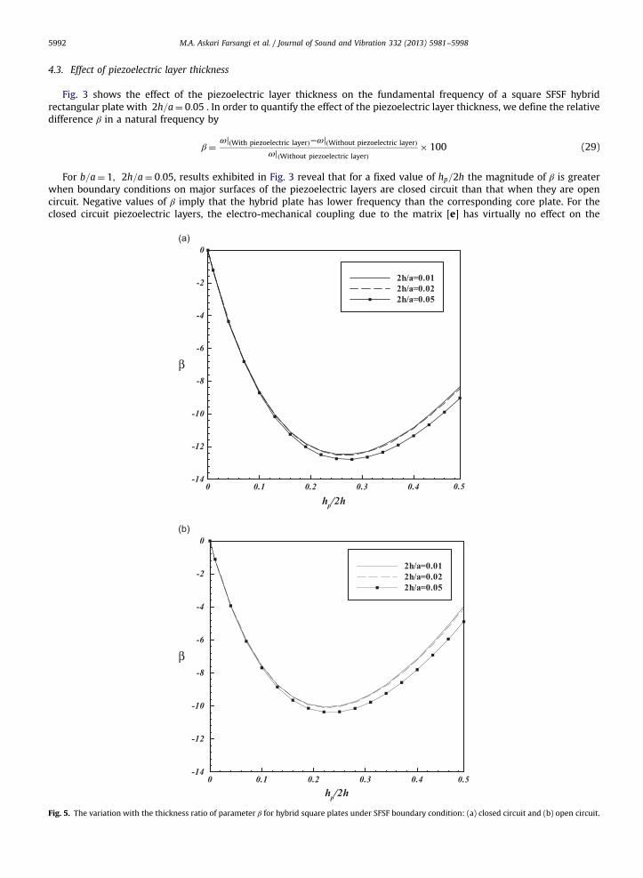
Fig. 5. The variation with the thickness ratio of parameter β for hybrid square plates under SFSF boundary condition: (a) closed circuit and (b) open circuit.
M.A. Askari Farsangi et al. / Journal of Sound and Vibration 332 (2013) 5981–5998 5993
fundamental frequency. Since the mass density of the piezoelectric material is higher than that of material of the core, themean density of the coupled structure increases with an increase in thickness ratio, hp=2h. Values of the elastic moduli ofthe core material are higher than that of the piezoelectric material. These two effects tend to decrease the frequency of thehybrid plate as compared to that of the homogeneous non-piezoelectric material plate. However, the electromechanicalcoupling tends to increase the frequency. Initially the mass density and the stiffness effects exceed those due toelectromechanical coupling. The electro-mechanical coupling effect increases with an increase in hp=2h and should increasethe value of β. Negative values of β for values of hp=2h considered in this work suggest that the electro-mechanical couplingeffect is less than that due to the combined effects of the increase in the mass density and the decrease in the stiffness. For asimilar problem studied by Batra and Liang considering 3-D deformations, the value of β was found to be negative for thefirst five frequencies.
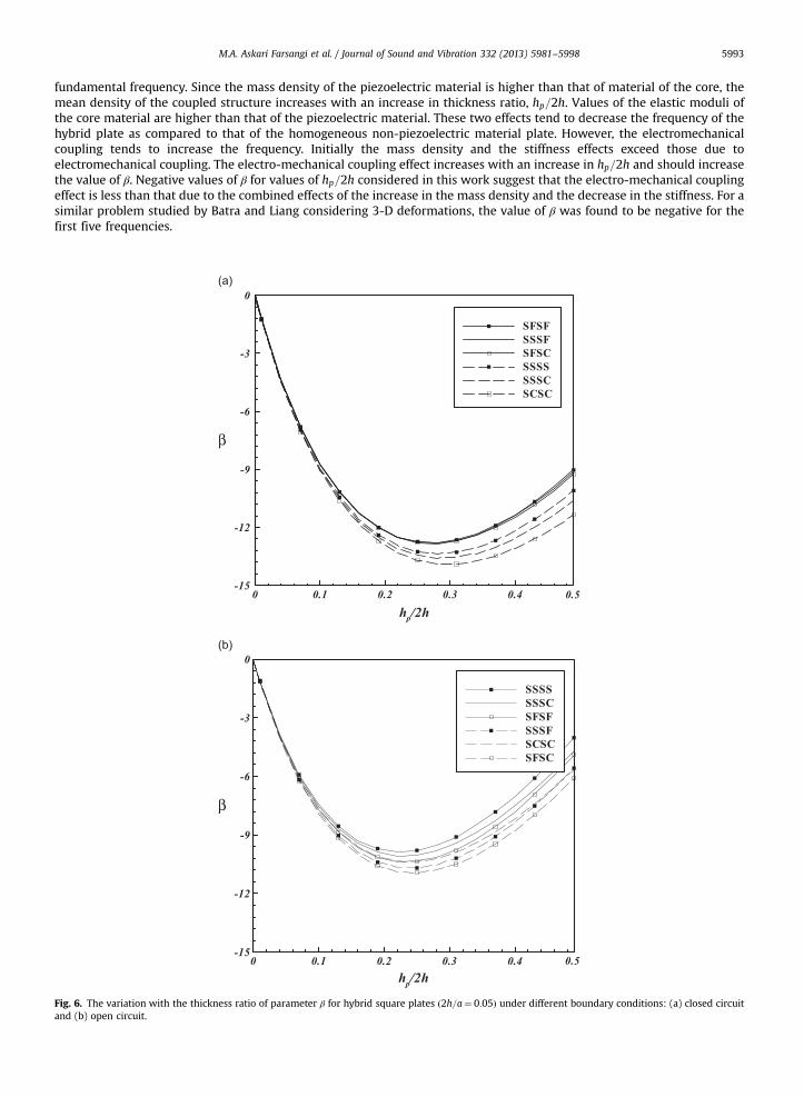
Fig. 6. The variation with the thickness ratio of parameter β for hybrid square plates ð2h=a¼ 0:05Þ under different boundary conditions: (a) closed circuitand (b) open circuit.
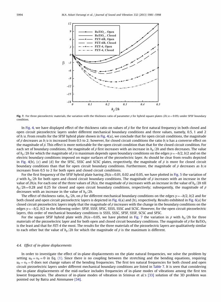
Fig. 7. For three piezoelectric materials, the variation with the thickness ratio of parameter β for hybrid square plates ð2h=a¼ 0:05Þ under SFSF boundarycondition.
M.A. Askari Farsangi et al. / Journal of Sound and Vibration 332 (2013) 5981–59985994
In Fig. 4, we have displayed effect of the thickness ratio on values of β for the first natural frequency in both closed andopen circuit piezoelectric layers under different mechanical boundary conditions and three values, namely, 0.5, 1 and 2of b=a. From results for the SFSF hybrid plate shown in Fig. 4(a), we conclude that for open circuit conditions, the magnitudeof β decreases as b=a is increased from 0.5 to 2; however, for closed circuit conditions the ratio b=a has a converse effect onthe magnitude of β. This effect is more noticeable for the open circuit condition than that for the closed circuit condition. Foreach set of boundary conditions, the magnitude of β first increases with an increase in hp=2h and then decreases. The valueof hp=2h for which the magnitude of β is maximum depends upon boundary conditions on the edges y¼−b/2, b/2 and on theelectric boundary conditions imposed on major surfaces of the piezoelectric layer. As should be clear from results depictedin Fig. 4(b), (c) and (d) for the SFSC, SSSC and SCSC plates, respectively, the magnitude of β is more for closed circuitboundary conditions than that for open circuit boundary conditions. Furthermore, the magnitude of β decreases as b=aincreases from 0.5 to 2 for both open and closed circuit conditions.
For the first frequency of the SFSF hybrid plate having 2h/a¼0.01, 0.02 and 0.05, we have plotted in Fig. 5 the variation ofβ with hp=2h for both open and closed circuit boundary conditions. The magnitude of β increases with an increase in thevalue of 2h/a. For each one of the three values of 2h/a, the magnitude of β increases with an increase in the value of hp=2h tillhp=2h¼0.28 and 0.25 for closed and open circuit boundary conditions, respectively; subsequently, the magnitude of βdecreases with an increase in the value of hp=2h.
The effect of thickness ratio, hp=2h, on β for different mechanical boundary conditions on the edges y¼−b/2, b/2 and forboth closed and open circuit piezoelectric layers is depicted in Fig. 6(a) and (b), respectively. Results exhibited in Fig. 6(a) forclosed circuit piezoelectric layers imply that the magnitude of β increases with the change in the boundary conditions on theedges y¼−b/2, b/2 in the following order: SFSF, SSSF, SFSC, SSSS, SSSC and SCSC. However, for the open circuit piezoelectriclayers, this order of mechanical boundary conditions is SSSS, SSSC, SFSF, SSSF, SCSC and SFSC.
For the square SFSF hybrid plate with 2h/a¼0.05, we have plotted in Fig. 7 the variation in β with hp=2h for threematerials of the piezoelectric layer and for both open and closed circuit boundary conditions. The magnitude of β for BaTiO3
is the least and that for PZT-4 the most. The results for the three materials of the piezoelectric layers are qualitatively similarto each other but the value of hp=2h for which the magnitude of β is the maximum is different.
4.4. Effect of in-plane displacements
In order to investigate the effect of in-plane displacements on the plate natural frequencies, we solve the problem bysetting u0 ¼ v0 ¼ 0 in Eq. (1). Since there is no coupling between the stretching and the bending equations, requiringu0 ¼ v0 ¼ 0 does not change values of the bending frequencies. The first ten natural frequencies for both closed and opencircuit piezoelectric layers under different mechanical boundary conditions are listed in Table 7. It is seen that consideringthe in-plane displacements of the mid-surface includes frequencies of in-plane modes of vibrations among the first tenlowest frequencies. The absence of in-plane modes of vibration in Srinivas et al.'s [33] solution of the 3D problem waspointed out by Batra and Aimmanee [34].
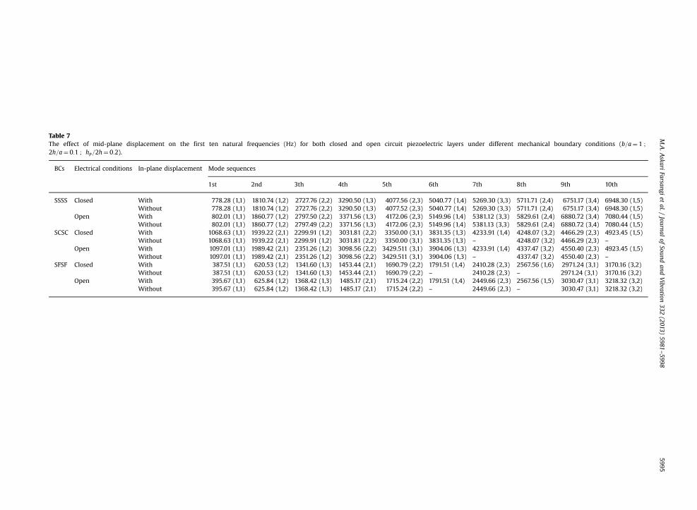
Table 7The effect of mid-plane displacement on the first ten natural frequencies (Hz) for both closed and open circuit piezoelectric layers under different mechanical boundary conditions (b=a¼ 1 ;
2h=a¼ 0:1 ; hp=2h¼ 0:2).
BCs Electrical conditions In-plane displacement Mode sequences
1st 2nd 3th 4th 5th 6th 7th 8th 9th 10th
SSSS Closed With 778.28 (1,1) 1810.74 (1,2) 2727.76 (2,2) 3290.50 (1,3) 4077.56 (2,3) 5040.77 (1,4) 5269.30 (3,3) 5711.71 (2,4) 6751.17 (3,4) 6948.30 (1,5)Without 778.28 (1,1) 1810.74 (1,2) 2727.76 (2,2) 3290.50 (1,3) 4077.52 (2,3) 5040.77 (1,4) 5269.30 (3,3) 5711.71 (2,4) 6751.17 (3,4) 6948.30 (1,5)
Open With 802.01 (1,1) 1860.77 (1,2) 2797.50 (2,2) 3371.56 (1,3) 4172.06 (2,3) 5149.96 (1,4) 5381.12 (3,3) 5829.61 (2,4) 6880.72 (3,4) 7080.44 (1,5)Without 802.01 (1,1) 1860.77 (1,2) 2797.49 (2,2) 3371.56 (1,3) 4172.06 (2,3) 5149.96 (1,4) 5381.13 (3,3) 5829.61 (2,4) 6880.72 (3,4) 7080.44 (1,5)
SCSC Closed With 1068.63 (1,1) 1939.22 (2,1) 2299.91 (1,2) 3031.81 (2,2) 3350.00 (3,1) 3831.35 (1,3) 4233.91 (1,4) 4248.07 (3,2) 4466.29 (2,3) 4923.45 (1,5)Without 1068.63 (1,1) 1939.22 (2,1) 2299.91 (1,2) 3031.81 (2,2) 3350.00 (3,1) 3831.35 (1,3) – 4248.07 (3,2) 4466.29 (2,3) –
Open With 1097.01 (1,1) 1989.42 (2,1) 2351.26 (1,2) 3098.56 (2,2) 3429.511 (3,1) 3904.06 (1,3) 4233.91 (1,4) 4337.47 (3,2) 4550.40 (2,3) 4923.45 (1,5)Without 1097.01 (1,1) 1989.42 (2,1) 2351.26 (1,2) 3098.56 (2,2) 3429.511 (3,1) 3904.06 (1,3) – 4337.47 (3,2) 4550.40 (2,3) –
SFSF Closed With 387.51 (1,1) 620.53 (1,2) 1341.60 (1,3) 1453.44 (2,1) 1690.79 (2,2) 1791.51 (1,4) 2410.28 (2,3) 2567.56 (1,6) 2971.24 (3,1) 3170.16 (3,2)Without 387.51 (1,1) 620.53 (1,2) 1341.60 (1,3) 1453.44 (2,1) 1690.79 (2,2) – 2410.28 (2,3) – 2971.24 (3,1) 3170.16 (3,2)
Open With 395.67 (1,1) 625.84 (1,2) 1368.42 (1,3) 1485.17 (2,1) 1715.24 (2,2) 1791.51 (1,4) 2449.66 (2,3) 2567.56 (1,5) 3030.47 (3,1) 3218.32 (3,2)Without 395.67 (1,1) 625.84 (1,2) 1368.42 (1,3) 1485.17 (2,1) 1715.24 (2,2) – 2449.66 (2,3) – 3030.47 (3,1) 3218.32 (3,2)
M.A.A
skariFarsangi
etal./
Journalof
Soundand
Vibration
332(2013)
5981–5998
5995
M.A. Askari Farsangi et al. / Journal of Sound and Vibration 332 (2013) 5981–59985996
5. Conclusions
We have used the first order shear deformation plate theory to study free vibrations of a transversely isotropicrectangular plate with surface bonded piezoelectric layers. Equations governing vibrations of the plate derived by usingHamilton's principle are uncoupled by introducing four auxiliary functions. The hybrid plate is simply supported on twoopposite edges with the electric potential prescribed there enabling us to use a Levy type solution. The uncoupled ordinarydifferential equations are solved analytically. Numerical results included in the paper enable us to draw the followingconclusions:
1.
For a hybrid plate with identical piezoelectric layers perfectly bonded to the top and the bottom surfaces of the coreplate, frequencies of transverse (bending) vibrations are independent of those for in-plane vibrations. Whereasfrequencies of in-plane vibrations are the same for the open circuit and the closed circuit boundary conditions onmajor surfaces of the piezoelectric layers, those of transverse vibrations are different.2.
For all boundary conditions except SFSF, plate's fundamental natural frequency increases with an increase in plate'saspect ratio (length/width).3.
For the material systems considered, an increase in the piezoelectric layer thickness first decreases the fundamentalnatural frequency of the hybrid plate till the difference between the two frequencies reaches a maximum. This criticalvalue of the piezoelectric layer thickness depends upon the material of the piezoelectric layer for a fixed material ofthe core.4.
For two opposite edges of a rectangular hybrid plate simply supported, boundary conditions on the other two edgesincrease the fundamental frequency in the following order: SFSF, SSSF, SFSC, SSSS, SSSC and SCSC for closed circuitpiezoelectric layers, and SSSS, SSSC, SFSF, SSSF, SCSC and SFSC for open circuit piezoelectric layers.5.
For open circuit boundary conditions the change in the natural frequency is due to the stiffness effect as well as thepiezoelectric effect, but for closed circuit boundary conditions it is due to the stiffness effect only.The three materials, namely, BaTiO3, PZT-6B and PZT-4, of the piezoelectric layer have qualitatively similar butquantitatively different effects on the fundamental frequency of the hybrid plate.Conflict of interest
None.
Appendix A
The constitutive relation for a thin transversely isotropic piezoelectric material plate polarized in the z-direction can bewritten as
sxxsyysxysxzsyz
8>>>>>><>>>>>>:
9>>>>>>=>>>>>>;
¼
c11 c12 0 0 0c12 c11 0 0 00 0 1
2 ðc11−c12Þ 0 0
0 0 0 K2c55 00 0 0 0 K2c55
26666664
37777775
εxx
εyy
γxyγxzγyz
8>>>>>><>>>>>>:
9>>>>>>=>>>>>>;−
0 0 e310 0 e310 0 0
−e15 0 00 −e15 0
26666664
37777775
ExEyEz
8><>:
9>=>; (A.1.1)
Dx
Dy
Dz
8><>:
9>=>;¼
0 0 0 e15 00 0 0 0 e15e31 e31 0 0 0
264
375
εxx
εyy
γxyγxzγyz
8>>>>>><>>>>>>:
9>>>>>>=>>>>>>;
þΞ11 0 00 Ξ11 00 0 Ξ33
264
375
ExEyEz
8><>:
9>=>; (A.1.2)
where
c11 ¼ c11−c132
c33; c12 ¼ c12−
c132
c33; e31 ¼ e31−
c13c33
e33; Ξ33 ¼ Ξ33 þe332
c33(A.1.3)
K2 is the shear correction factor [26]Coefficients in Eqs. (16) are defined as
ðA′11;A
′12Þ ¼
Z h
−hðQ11;Q12Þdzþ 2
Z hþhp
hðc11; c12Þdzþ μ7 (A.2.1)
A′55 ¼Z h
−hQ55dzþ 2
Z hþhp
hc55dz (A.2.2)
M.A. Askari Farsangi et al. / Journal of Sound and Vibration 332 (2013) 5981–5998 5997
A′66 ¼
Z h
−hQ66dzþ
Z hþhp
hðc11−c12Þdz (A.2.3)
ðD′11;D
′12Þ ¼
Z h
−hðQ11;Q12Þz2dzþ 2
Z hþhp
hðc11; c12Þz2dzþ μ8 (A.2.4)
D′66 ¼
Z h
−hQ66z
2dzþZ hþhp
hðc11−c12Þz2dz (A.2.5)
Coefficients in Eqs. (22) are given by
λ1 ¼ μ3λ″3λ
′1 þ μ1λ
″3λ′þ μ2λ
′1 þ D′
11λ′11 (A.3.1)
λ2 ¼ μ3λ″3λ
′2 þ μ1λ
″3λ
′2 þ μ3λ
″1 þ μ1λ
″1 þ μ2λ
′2 þ D′
11λ′2 þ I2λ′1ω
2m−K
2A′55λ
′1 (A.3.2)
λ3 ¼ μ3λ″3λ
′3 þ μ1λ
″3λ
′3 þ μ3λ
″2 þ μ2λ
′3 þ μ1λ
″2 þ D′
11λ′3 þ I2λ′2ω
2m−K
2A′55λ
′2−K
2A′55 (A.3.3)
λ4 ¼ I2λ′3ω2m−K
2A′55λ
′3 (A.3.4)
λ′1 ¼S2μ3λ
″1
S3þ S2μ1λ
″1
S3þ S1μ3λ
″1
S3(A.3.5)
λ′2 ¼S2μ3λ
″2
S3þ S1μ3λ
″2
S3þ S2μ1λ
″2
S3−S2K
2A′55
S3−S1K
2A′55
S3; λ′3 ¼−
I0S1ω2m
S3(A.3.6–7)
λ′1 ¼K2A′
55
μ6−μ4μ6
; λ″2 ¼I0ω2
m
μ6; λ″3 ¼
K2A′55
μ6−μ5μ6
(A.3.8–10)
where
Closed� Circuit : μ1 ¼−4e31hp
3; μ2 ¼ 0; μ3 ¼
8Ξ11hp9
; μ4 ¼4e15hp
3
Open� Circuit : μ1 ¼8e31ð3hþ hpÞ
3; μ2 ¼
e15e31h2pðhþ hpÞ
Ξ33; μ3 ¼
16e15hp3
; μ4 ¼2e215hpΞ11
Closed� Circuit : μ5 ¼4hp3
ðe31 þ e15Þ; μ6 ¼32Ξ33
3hp; μ7 ¼ 0; μ8 ¼ 0
Open� Circuit : μ5 ¼2e215hpΞ11
þ 2e31e15hpΞ11
; μ6 ¼16e15Ξ33
Ξ11hp; μ7 ¼
2e231hpΞ33
; μ8 ¼e231hpðhþ hpÞð2hþ hpÞ
Ξ33(A.3.11)
Furthermore,
S1 ¼D′11 þ μ1λ
″3 þ μ3λ
″3 þ μ2 (A.3.12)
S2 ¼−μ3λ″3−μ2 (A.3.13)
S3 ¼ S2I2 þ K2A55ðS1 þ S2Þ (A.3.14)
η4 ¼
ffiffiffiffiffiffiffiffiffiffiffiffiffiffiffiffiffiffiffiffiffiffiffiffiffiffiffiffiffiβj
2A′33−I0ω2
m
A′11
vuut (A.4.1)
η5 ¼
ffiffiffiffiffiffiffiffiffiffiffiffiffiffiffiffiffiffiffiffiffiffiffiffiffiffiffiffiffiffiffiβj
2A′66−I0ω2
m2
A′66
vuut (A.4.2)
η6 ¼
ffiffiffiffiffiffiffiffiffiffiffiffiffiffiffiffiffiffiffiffiffiffiffiffiffiffiffiffiffiffiffiffiffiffiffiffiffiffiffiffiffiffiffiffiffiffiffiffiβj
2D′66 þ K2A″
66−I2ω2m
D′66
vuut (A.4.3)
References
[1] H. Sumali, K. Meissner, H.H. Cudney, A piezoelectric array for sensing vibration modal coordinates, Sensors and Actuators A 93 (2001) 123–131.[2] T. Wu, Modeling and Design of a Novel Cooling Device for Microelectronics using Piezoelectric Resonating Beams, PhD Thesis Department of
Mechanical and Aerospace Engineering, North Carolina State University, 2003.
M.A. Askari Farsangi et al. / Journal of Sound and Vibration 332 (2013) 5981–59985998
[3] F. Casadei, L. Dozio, M. Ruzzene, K.A. Cunefare, Periodic shunted arrays for the control of noise radiation in an enclosure, Journal of Sound and Vibration329 (2010) 3632–3646.
[4] D.H. Cortes, S.K. Datta, O.M. Mukdadi, Elastic guided wave propagation in a periodic array of multi-layered piezoelectric plates with finite cross-sections, Ultrasonics 50 (2010) 347–356.
[5] Z. Hao, B. Liao, An analytical study on interfacial dissipation in piezoelectric rectangular block resonators with in-plane longitudinal-mode vibrations,Sensors and Actuators A 163 (2010) 401–409.
[6] H.F. Tiersten, Linear Piezoelectric Plate Vibrations, Plenum, New York, 1969.[7] J. Wang, J. Yang, Higher-order theories of piezoelectric plates and applications, Reprinted from Applied Mechanics Reviews 53(4) (2000) 87–99.[8] R.C. Batra, S. Vidoli, Higher order piezoelectric plate theory derived from a three-dimensional variational principle, AIAA Journal 40 (1) (2002) 91–104.[9] H.S. Tzou, C.I. Tseng, Distributed piezoelectric sensor/actuator design for dynamic measurement/control of distributed parameter systems: a
piezoelectric finite element approach, Journal of Sound and Vibration 138 (1) (1990) 17–34.[10] P. Heyliger, S. Brooks, Free vibration of piezoelectric laminates in cylindrical bending, International Journal of Solids and Structures 32 (20) (1995)
2945–2960.[11] R.C. Batra, X.Q. Liang, J.S. Yang, The vibration of simply supported rectangular elastic plate due to piezoelectric actuators, International Journal of Solids
and Structures 33 (11) (1996) 1597–1618.[12] J.N. Reddy, On laminated composite plates with integrated sensors and actuators, Engineering Structures 21 (1999) 568–593.[13] S.S. Vel, R.C. Mewer, R.C. Batra, Analytical solution for the cylindrical bending vibration of piezoelectric composite plates, International Journal of Solids
and Structures 41 (2004) 1625–1643.[14] B.P. Baillargeon, S.S. Vel, Exact solution for the vibration and active damping of composite plates with piezoelectric shear actuators, Journal of Sound
and Vibration 282 (2005) 781–804.[15] G. Akhras, W.C. Li, Three-dimensional static, vibration and stability analysis of piezoelectric composite plates using a finite layer method, Smart
Material and Structures 16 (2007) 561–569.[16] P. Topdar, A.H. Sheikh, N. Dhang, Vibration characteristics of composite/sandwich laminates with piezoelectric layers using a refined hybrid plate
model, International Journal of Mechanical Sciences 49 (2007) 1193–1203.[17] M. Pietrzakowski, Piezoelectric control of composite plate vibration: effect of electric potential distribution, Computers and Structures 86 (2008)
948–954.[18] D.F. Torres, P.R. Mendonça, HSDT-layerwise analytical solution for rectangular piezoelectric laminated plates, Composite Structures 92 (2010)
1763–1774.[19] J. Jin, R.C. Batra, Effect of electromechanical coupling on static deformations and natural frequencies, IEEE Transactions on Ultrasonics, Ferroelectrics, and
Frequency Control 52 (7) (2005) 1079–1093.[20] X.Q. Liang, R.C. Batra, Changes in frequencies of a laminated plate caused by embedded piezoelectric layers, AIAA Journal. 35 (1997) 1672–1673.[21] C.L. Davis, G.A. Lesieutre, An actively tuned solid-state vibration absorber using capacitive shunting of piezoelectric stiffness, Journal of Sound and
Vibration 232 (3) (2000) 601–617.[22] N. Wu, Q. Wang, S.T. Quek, Free vibration analysis of piezoelectric coupled circular plate, Journal of Sound and Vibration 329 (2010) 1126–1136.[23] W.H. Duan, S.T. Quek, Q. Wang, Free vibration analysis of piezoelectric coupled thin and thick annular plate, Journal of Sound and Vibration 281 (2005)
119–139.[24] P.R.Heyliger, Exact solutions for simply supported piezoelectric plates, Journal of Applied Mechanics 46(1997) 299–306.[25] D.A. Saravanos, P.R. Heyliger, D.A. Hopkins, Layerwise machanics and finite element for the dynamic analysis of piezoelectric composite plates,
International Journal of Solids and Structures 34 (1997) 359–378.[26] J.N. Reddy, Energy and Variational Methods in Applied Mechanics, John Wiley & Sons, New York, 1984.[27] Q. Wang, S.T. Quek, C.T. Sun, X. Liu, Analysis of piezoelectric coupled circular plate, Smart Materials and Structures 10 (2) (2001) 229.[28] Sh. Hosseini Hashemi, S.R. Atashipour, M. Fadaee, An exact analytical approach for in-plane and out-of-plane free vibration analysis of thick laminated
transversely isotropic plates, Archive of Applied Mechanics 82 (5) (2012) 677–698.[29] A. Hasani Baferani, A.R. Saidi, H. Ehteshami, Accurate solution for free vibration analysis of functionally graded thick rectangular plates resting on
elastic foundation, Composite Structures 93 (7) (2011) 1842–1853.[30] X.Q. He, T.Y. Ng, S. Sivashanker, K.M. Liew, Active control of FGM plates with integrated piezoelectric sensors and actuators, International Journal of
Solids and Structures 38 (2001) 1641–1655.[31] A.W. Leissa, Vibration of Plates, NASA Report SP-160, Washington, DC, 1969.[32] A. Hasani Baferani, A.R. Saidi, E. Jomehzadeh, An exact solution for free vibration of thin functionally graded rectangular plates, Proceedings of the
Institution of Mechanical Engineers, Part C: Journal of Mechanical Engineering Science 225 (3) (2011) 526–536.[33] S. Srinivas, C.V.J. Rao, A.K. Rao, An exact analysis for vibration of simply supported homogeneous and laminate thick rectangular plates, Journal of
Sound and Vibration 12 (1970) 187–199.[34] R.C. Batra, S. Aimmanee, Missing frequencies in previous exact solutions of free vibrations of simply supported rectangular plates, Journal of Sound and
Vibration 265 (2003) 887–896.[35] J.Y. Chen, H.L. Chen, E. Pan, P.R. Heyliger, Modal analysis of magneto-electro-elastic plates using the state-vector approach, Journal of Sound and
Vibration 304 (2007) 722–734.[36] F. Ramirez, P.R. Heyliger, E. Pan, Free vibration response of two-dimensional magneto-electro-elastic laminated plates, Journal of Sound and Vibration
292 (2006) 626–644.[37] S. Kapuria, P. Kumari, Extended Kantorovich method for coupled piezoelasticity solution of piezolaminated plates showing edge effects, Proceedings of
the Royal Society A—Mathematical Physical and Engineering Sciences. 469 (2013) Article Number: 20120565.[38] S. Kapuria, J.K. Nath, Coupled global-local and zigzag-local laminate theories for dynamic analysis of piezoelectric laminated plates, Journal of Sound
and Vibration 292 (2013) 306–325.[39] S.S. Vel, R.C. Batra, Three-dimensional analytical solution for hybrid multilayered piezoelectric plates, Journal of Applied Mechanics 67 (2000)
558–567.[40] R.C. Batra, X.Q. Liang, Finite dynamic deformations of smart structures, Computational Mechanics 20 (1987) 427–438.[41] R.C. Batra, T.S. Geng, Enhancement of the dynamic buckling load for a plate by using piezoceramic actuators, Smart Materials and Structures 10 (2001)
925–933.[42] S. Kapuria, P. Kumari, J.K. Nath, Efficient modeling of smart piezoelectric composite laminates: a review, Acta Mechanica 214 (2010) 31–48.[43] L. Edery-Azulay, H. Abramovich, Piezolaminated plates—highly accurate solutions based on the extended Kantorovich method, Composite Structures 84
(2008) 241–247.[44] A. Benjeddou, New insights in piezoelectric free-vibrations using simplified modeling and analyses, Smart Structures and Systems 5 (2009) 591–612.[45] S.M. Shiyekar, T. Kant, An electromechanical higher order model for piezoelectric functionally graded plates, International Journal of Mechanics and
Materials in Design 6 (2010) 163–174.[46] J.S. Yang, R.C. Batra, Free vibrations of a piezoelectric body, Journal of Elasticity 34 (1994) 239–254.[47] Chopra, Review of State-of-Art of Smart Structures and Integrated Systems, AIAA Journal 40 (2002) 2145–2187.[48] J.S. Yang and R.C. Batra, Free Vibrations of a Linear Thermopiezoelectric Body, J. Thermal Stresses 18 (1995) 247–262.
![Free vibration analysis of piezoelectric cylindrical nanoshell ......vibration analysis of shallow shells [25]. Loy et al. presented the free vibration analysis of cylindrical shells](https://img.pdfslide.us/doc/110x75/5f736ba706f884064751d11e/free-vibration-analysis-of-piezoelectric-cylindrical-nanoshell-vibration.jpg)


![1. Introduction - New York Universitystadler/papers/confric.pdf · nonlinear thin piezoelectric shells, and [27] for the modelling of eigenvalue problems for thin piezoelectric shells](https://img.pdfslide.us/doc/110x75/5b0468d47f8b9a4e538daf92/1-introduction-new-york-university-stadlerpapers-thin-piezoelectric-shells.jpg)