Embed Size (px)
Citation preview
lable at ScienceDirect
Journal of Power Sources 273 (2015) 96e104
Contents lists avai
Journal of Power Sources
journal homepage: www.elsevier .com/locate/ jpowsour
Thermal conductivity of a graphite bipolar plate (BPP) and its thermalcontact resistance with fuel cell gas diffusion layers: Effect ofcompression, PTFE, micro porous layer (MPL), BPP out-of-flatness andcyclic load
Hamidreza Sadeghifar a, b, Ned Djilali b, c, Majid Bahrami a, *
a Laboratory for Alternative Energy Conversion (LAEC), School of Mechatronic Systems Engineering, Simon Fraser University, Surrey V3T 0A3, BC, Canadab Institute for Integrated Energy Systems, University of Victoria, Victoria V8W 3P6, BC, Canadac Department of Mechanical Engineering, University of Victoria, Victoria V8W 3P6, BC, Canada
h i g h l i g h t s
* Corresponding author. Tel.: þ1 (778) 782 8538; fE-mail addresses: [email protected] (H. Sadeghifar)
[email protected] (M. Bahrami).
http://dx.doi.org/10.1016/j.jpowsour.2014.09.0620378-7753/© 2014 Elsevier B.V. All rights reserved.
g r a p h i c a l a b s t r a c t
� Thermal conductivity of graphite bi-polar plates (BPP) decreases withtemperature.
� Thermal Contact resistance (TCR)between BPP and GDLs decreaseswith compression.
� GDL-BPP TCR increases with MPL andPTFE, regardless of the PTFE loading.
� High PTFE loading, MPL, and BPP out-of-flatness increase the TCRdramatically.
� The graphite BPP-GDL TCR is adominant resistance in a BPP-GDLassembly.
a r t i c l e i n f o
Article history:Received 18 November 2013Received in revised form5 September 2014Accepted 8 September 2014Available online 18 September 2014
Keywords:Graphite bipolar plateThermal conductivityThermal contact resistanceGas diffusion layerPTFEMPL
a b s t r a c t
This paper reports on measurements of thermal conductivity of a graphite bipolar plate (BPP) as afunction of temperature and its thermal contact resistance (TCR) with treated and untreated gas diffusionlayers (GDLs). The thermal conductivity of the BPP decreases with temperature and its thermal contactresistance with GDLs, which has been overlooked in the literature, is found to be dominant over arelatively wide range of compression. The effects of PTFE loading, micro porous layer (MPL), compression,and BPP out-of-flatness are also investigated experimentally. It is found that high PTFE loadings, MPL andeven small BPP out-of-flatness increase the BPP-GDL thermal contact resistance dramatically. The paperalso presents the effect of cyclic load on the total resistance of a GDL-BPP assembly, which sheds light onthe behavior of these materials under operating conditions in polymer electrolyte membrane fuel cells.
© 2014 Elsevier B.V. All rights reserved.
ax: þ1 (778) 782 7514., [email protected] (N. Djilali),
H. Sadeghifar et al. / Journal of Power Sources 273 (2015) 96e104 97
1. Introduction
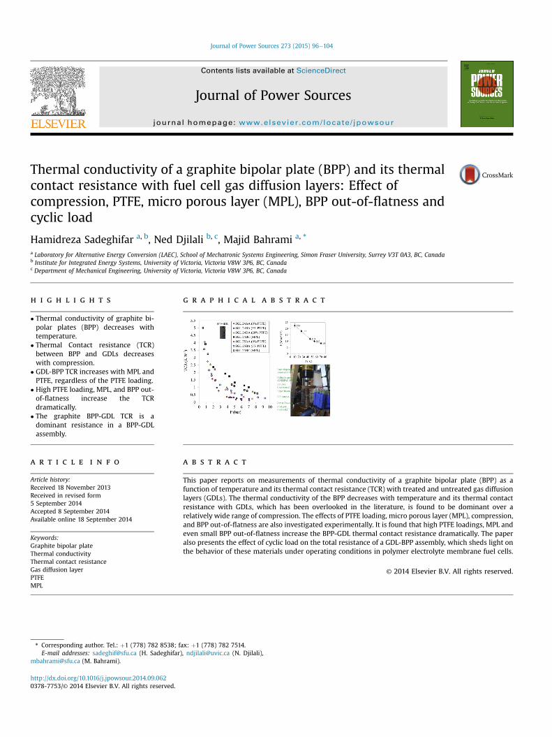
The required power output of proton exchange membrane fuelcells (PEMFCs) for specific applications is achieved by stacking in-dividual cells or membrane electrode assemblies (MEAs), eachseparated by a bipolar plate (BPP). Fig. 1 illustrates the componentsof a PEMFC, including the BPPs and their adjacent GDLs, and all themain thermal resistances within the cell.
The adequate thermal and associated water management offuel cells requires knowledge of the thermal bulk and contactresistances of all involved components [1,2]. However, due toexperimental difficulties, no measurements have been reported todate on the thermal contact resistance (TCR) between GDLs andgraphite BPP [3e6]. Consequently, this contact resistance haseither been neglected or roughly estimated in modeling studies[7e10]. The brittle, porous anisotropic nature of most fuel cellcomponents together with their small thicknesses have made itchallenging to measure their thermal resistances, e.g. see Refs.[6,11e16].
The only attempt to estimate the thermal contact resistancebetween BPP and GDLs to date is due to Nitta et al. [17], which wasbased on simulations using Fluent, with an unverified assumptionof 128 Wm�1 K�1 for the thermal conductivity of the graphite BPP.The reported thermal conductivity of the GDL was several timeshigher than typical values found in the literature and was also in-dependent of compression. These results are inconsistent withphysical observations [18e25] and with several experimentalstudies showing significant dependency of GDL thermal conduc-tivity on compression [11e15,19e21].
The main purpose of the present study is to measure andanalyze the behavior of thermal conductivity of the graphite BPP interms of temperature and its thermal contact resistance withdifferent untreated and treated GDLs over a range of compression.This work provides some key data and insights on the effect of
Fig. 1. (a) Main components of a PEMFC and (b) a
Polytetrafluoroethylene (PTFE), micro porous layer (MPL), BPP out-of-flatness and cyclic loading on the GDL-BPP TCR.
2. Experimental setup
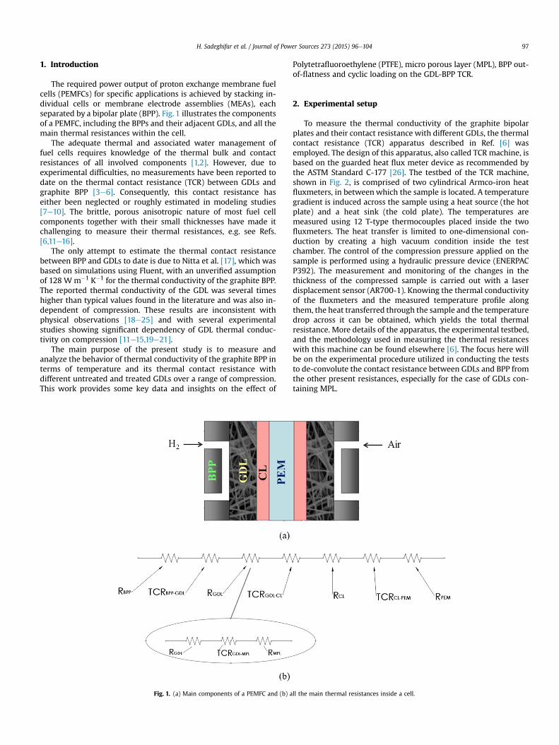
To measure the thermal conductivity of the graphite bipolarplates and their contact resistance with different GDLs, the thermalcontact resistance (TCR) apparatus described in Ref. [6] wasemployed. The design of this apparatus, also called TCR machine, isbased on the guarded heat flux meter device as recommended bythe ASTM Standard C-177 [26]. The testbed of the TCR machine,shown in Fig. 2, is comprised of two cylindrical Armco-iron heatfluxmeters, in betweenwhich the sample is located. A temperaturegradient is induced across the sample using a heat source (the hotplate) and a heat sink (the cold plate). The temperatures aremeasured using 12 T-type thermocouples placed inside the twofluxmeters. The heat transfer is limited to one-dimensional con-duction by creating a high vacuum condition inside the testchamber. The control of the compression pressure applied on thesample is performed using a hydraulic pressure device (ENERPACP392). The measurement and monitoring of the changes in thethickness of the compressed sample is carried out with a laserdisplacement sensor (AR700-1). Knowing the thermal conductivityof the fluxmeters and the measured temperature profile alongthem, the heat transferred through the sample and the temperaturedrop across it can be obtained, which yields the total thermalresistance. More details of the apparatus, the experimental testbed,and the methodology used in measuring the thermal resistanceswith this machine can be found elsewhere [6]. The focus here willbe on the experimental procedure utilized in conducting the teststo de-convolute the contact resistance between GDLs and BPP fromthe other present resistances, especially for the case of GDLs con-taining MPL.
ll the main thermal resistances inside a cell.
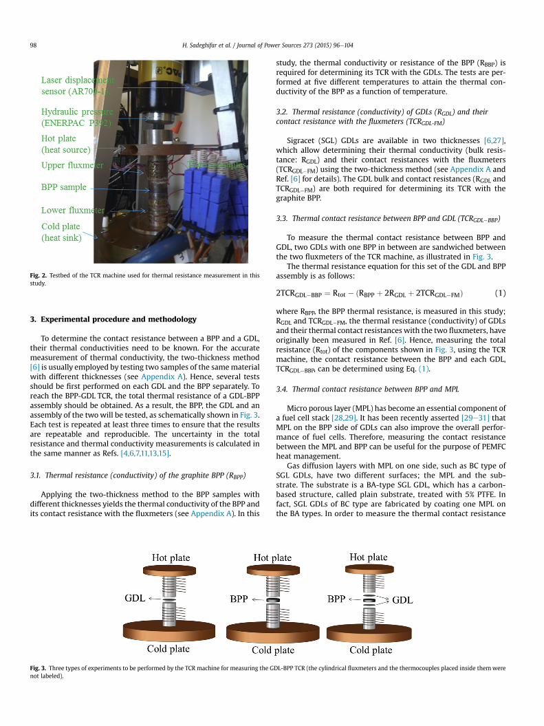
Fig. 2. Testbed of the TCR machine used for thermal resistance measurement in thisstudy.
H. Sadeghifar et al. / Journal of Power Sources 273 (2015) 96e10498
3. Experimental procedure and methodology
To determine the contact resistance between a BPP and a GDL,their thermal conductivities need to be known. For the accuratemeasurement of thermal conductivity, the two-thickness method[6] is usually employed by testing two samples of the samematerialwith different thicknesses (see Appendix A). Hence, several testsshould be first performed on each GDL and the BPP separately. Toreach the BPP-GDL TCR, the total thermal resistance of a GDL-BPPassembly should be obtained. As a result, the BPP, the GDL and anassembly of the twowill be tested, as schematically shown in Fig. 3.Each test is repeated at least three times to ensure that the resultsare repeatable and reproducible. The uncertainty in the totalresistance and thermal conductivity measurements is calculated inthe same manner as Refs. [4,6,7,11,13,15].
3.1. Thermal resistance (conductivity) of the graphite BPP (RBPP)
Applying the two-thickness method to the BPP samples withdifferent thicknesses yields the thermal conductivity of the BPP andits contact resistance with the fluxmeters (see Appendix A). In this
Fig. 3. Three types of experiments to be performed by the TCR machine for measuring the Gnot labeled).
study, the thermal conductivity or resistance of the BPP (RBBP) isrequired for determining its TCR with the GDLs. The tests are per-formed at five different temperatures to attain the thermal con-ductivity of the BPP as a function of temperature.
3.2. Thermal resistance (conductivity) of GDLs (RGDL) and theircontact resistance with the fluxmeters (TCRGDL-FM)
Sigracet (SGL) GDLs are available in two thicknesses [6,27],which allow determining their thermal conductivity (bulk resis-tance: RGDL) and their contact resistances with the fluxmeters(TCRGDL�FM) using the two-thickness method (see Appendix A andRef. [6] for details). The GDL bulk and contact resistances (RGDL andTCRGDL�FM) are both required for determining its TCR with thegraphite BPP.
3.3. Thermal contact resistance between BPP and GDL (TCRGDL�BBP)
To measure the thermal contact resistance between BPP andGDL, two GDLs with one BPP in between are sandwiched betweenthe two fluxmeters of the TCR machine, as illustrated in Fig. 3.
The thermal resistance equation for this set of the GDL and BPPassembly is as follows:
2TCRGDL�BBP ¼ Rtot � ðRBPP þ 2RGDL þ 2TCRGDL�FMÞ (1)
where RBPP, the BPP thermal resistance, is measured in this study;RGDL and TCRGDL�FM, the thermal resistance (conductivity) of GDLsand their thermal contact resistances with the two fluxmeters, haveoriginally been measured in Ref. [6]. Hence, measuring the totalresistance (Rtot) of the components shown in Fig. 3, using the TCRmachine, the contact resistance between the BPP and each GDL,TCRGDL�BBP, can be determined using Eq. (1).
3.4. Thermal contact resistance between BPP and MPL
Micro porous layer (MPL) has become an essential component ofa fuel cell stack [28,29]. It has been recently asserted [29e31] thatMPL on the BPP side of GDLs can also improve the overall perfor-mance of fuel cells. Therefore, measuring the contact resistancebetween the MPL and BPP can be useful for the purpose of PEMFCheat management.
Gas diffusion layers with MPL on one side, such as BC type ofSGL GDLs, have two different surfaces; the MPL and the sub-strate. The substrate is a BA-type SGL GDL, which has a carbon-based structure, called plain substrate, treated with 5% PTFE. Infact, SGL GDLs of BC type are fabricated by coating one MPL onthe BA types. In order to measure the thermal contact resistance
DL-BPP TCR (the cylindrical fluxmeters and the thermocouples placed inside themwere
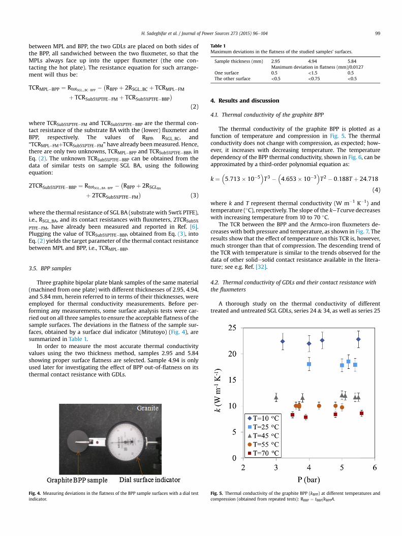
Table 1Maximum deviations in the flatness of the studied samples' surfaces.
Sample thickness (mm) 2.95 4.94 5.84Maximum deviation in flatness (mm)/0.0127
One surface 0.5 <1.5 0.5The other surface <0.5 <0.75 <0.5
H. Sadeghifar et al. / Journal of Power Sources 273 (2015) 96e104 99
between MPL and BPP, the two GDLs are placed on both sides ofthe BPP, all sandwiched between the two fluxmeter, so that theMPLs always face up into the upper fluxmeter (the one con-tacting the hot plate). The resistance equation for such arrange-ment will thus be:
TCRMPL�BPP ¼ RtotSGL BC�BPP ��RBPP þ 2RSGL BC þ TCRMPL�FM
þ TCRSub5%PTFE�FM þ TCRSub5%PTFE�BBP�
(2)
where TCRSub5%PTFE�FM and TCRSub5%PTFE�BBP are the thermal con-tact resistance of the substrate BA with the (lower) fluxmeter andBPP, respectively. The values of RBPP, RSGL_BC, and“TCRMPL�FMþTCRSub5%PTFE�FM” have already beenmeasured. Hence,there are only two unknowns, TCRMPL�BPP and TCRSub5%PTFE�BBP, inEq. (2). The unknown TCRSub5%PTFE�BBP can be obtained from thedata of similar tests on sample SGL BA, using the followingequation:
2TCRSub5%PTFE�BBP ¼ RtotSGL BA�BPP ��RBPP þ 2RSGLBA
þ 2TCRSub5%PTFE�FM�
(3)
where the thermal resistance of SGL BA (substratewith 5wt% PTFE),i.e., RSGL_BA, and its contact resistances with fluxmeters, 2TCRSub5%
PTFE�FM, have already been measured and reported in Ref. [6].Plugging the value of TCRSub5%PTFE�BBP, obtained from Eq. (3), intoEq. (2) yields the target parameter of the thermal contact resistancebetween MPL and BPP, i.e., TCRMPL�BBP.
3.5. BPP samples
Three graphite bipolar plate blank samples of the same material(machined from one plate) with different thicknesses of 2.95, 4.94,and 5.84 mm, herein referred to in terms of their thicknesses, wereemployed for thermal conductivity measurements. Before per-forming any measurements, some surface analysis tests were car-ried out on all three samples to ensure the acceptable flatness of thesample surfaces. The deviations in the flatness of the sample sur-faces, obtained by a surface dial indicator (Mitutoyo) (Fig. 4), aresummarized in Table 1.
In order to measure the most accurate thermal conductivityvalues using the two thickness method, samples 2.95 and 5.84showing proper surface flatness are selected. Sample 4.94 is onlyused later for investigating the effect of BPP out-of-flatness on itsthermal contact resistance with GDLs.
Fig. 4. Measuring deviations in the flatness of the BPP sample surfaces with a dial testindicator.
4. Results and discussion
4.1. Thermal conductivity of the graphite BPP
The thermal conductivity of the graphite BPP is plotted as afunction of temperature and compression in Fig. 5. The thermalconductivity does not change with compression, as expected; how-ever, it increases with decreasing temperature. The temperaturedependency of the BPP thermal conductivity, shown in Fig. 6, can beapproximated by a third-order polynomial equation as:
k ¼�5:713� 10�5
�T3 �
�4:653� 10�3
�T2 � 0:188T þ 24:718
(4)
where k and T represent thermal conductivity (W m�1 K�1) andtemperature (�C), respectively. The slope of the keT curve decreaseswith increasing temperature from 10 to 70 �C.
The TCR between the BPP and the Armco-iron fluxmeters de-creases with both pressure and temperature, as shown in Fig. 7. Theresults show that the effect of temperature on this TCR is, however,much stronger than that of compression. The descending trend ofthe TCR with temperature is similar to the trends observed for thedata of other solidesolid contact resistance available in the litera-ture; see e.g. Ref. [32].
4.2. Thermal conductivity of GDLs and their contact resistance withthe fluxmeters
A thorough study on the thermal conductivity of differenttreated and untreated SGL GDLs, series 24& 34, as well as series 25
Fig. 5. Thermal conductivity of the graphite BPP (kBPP) at different temperatures andcompression (obtained from repeated tests): RBBP ¼ tBBP/kBPPA.
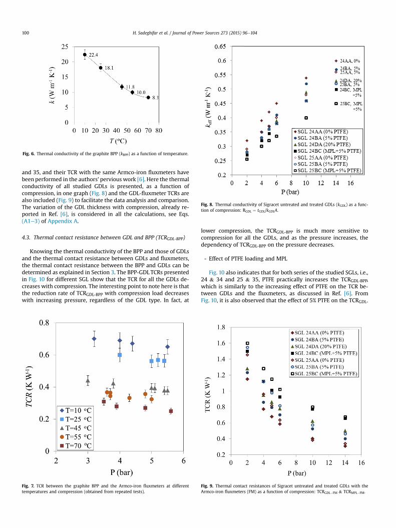
Fig. 6. Thermal conductivity of the graphite BPP (kBPP) as a function of temperature.
Fig. 8. Thermal conductivity of Sigracet untreated and treated GDLs (kGDL) as a func-tion of compression: RGDL ¼ tGDL/kGDLA.
H. Sadeghifar et al. / Journal of Power Sources 273 (2015) 96e104100
and 35, and their TCR with the same Armco-iron fluxmeters havebeen performed in the authors' pervious work [6]. Here the thermalconductivity of all studied GDLs is presented, as a function ofcompression, in one graph (Fig. 8) and the GDL-fluxmeter TCRs arealso included (Fig. 9) to facilitate the data analysis and comparison.The variation of the GDL thickness with compression, already re-ported in Ref. [6], is considered in all the calculations, see Eqs.(A1e3) of Appendix A.
4.3. Thermal contact resistance between GDL and BPP (TCRGDL-BPP)
Knowing the thermal conductivity of the BPP and those of GDLsand the thermal contact resistance between GDLs and fluxmeters,the thermal contact resistance between the BPP and GDLs can bedetermined as explained in Section 3. The BPP-GDL TCRs presentedin Fig. 10 for different SGL show that the TCR for all the GDLs de-creases with compression. The interesting point to note here is thatthe reduction rate of TCRGDL-BPP with compression load decreaseswith increasing pressure, regardless of the GDL type. In fact, at
Fig. 7. TCR between the graphite BPP and the Armco-iron fluxmeters at differenttemperatures and compression (obtained from repeated tests).
lower compression, the TCRGDL-BPP is much more sensitive tocompression for all the GDLs, and as the pressure increases, thedependency of TCRGDL-BPP on the pressure decreases.
- Effect of PTFE loading and MPL
Fig. 10 also indicates that for both series of the studied SGLs, i.e.,24 & 34 and 25 & 35, PTFE practically increases the TCRGDL-BPP,which is similarly to the increasing effect of PTFE on the TCR be-tween GDLs and the fluxmeters, as discussed in Ref. [6]. FromFig. 10, it is also observed that the effect of 5% PTFE on the TCRGDL-
Fig. 9. Thermal contact resistances of Sigracet untreated and treated GDLs with theArmco-iron fluxmeters (FM) as a function of compression: TCRGDL�FM & TCRMPL�FM.
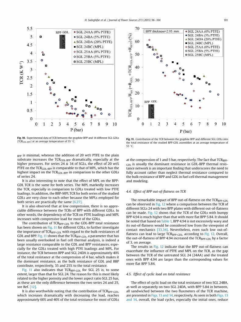
Fig. 10. Experimental data of TCR between the graphite BPP and 14 different SGL GDLs(TCRGDL-BPP) at an average temperature of 55 �C.
Fig. 11. Contribution of the TCR between the graphite BPP and different SGL GDLs intothe total resistance of the studied BPP-GDL assemblies at an average temperature of55 �C.
H. Sadeghifar et al. / Journal of Power Sources 273 (2015) 96e104 101
BPP is minimal, whereas the addition of 20 wt% PTFE to the plainsubstrate increases the TCRGDL-BPP dramatically, especially at thehigher pressures. For series 24 & 34 of SGLs, the effect of 20 wt%PTFE on the TCRGDL-BPP is comparable to that of MPL, which has thehighest impact on the TCRGDL-BPP in comparison to the other GDLsof series 24.
It is also interesting to note that the effect of MPL on the BPP-GDL TCR is the same for both series. The MPL markedly increasesthe TCR, especially in comparison to GDLs treated with low PTFEloadings. In addition, the BBP-MPLTCR for both series of the studiedGDLs are very close to each other because the MPLs employed forboth series are practically the same [6,27].
It is also observed that at low compression, there is no appre-ciable difference between the TCRs of BPP with different GDLs. Inother words, the dependency of the TCR on PTFE loadings and MPLincreases with compressive load for most of the GDLs.
The contribution of TCRBPP-GDL to the GDL-BPP total resistancehas been shown on Fig. 11 for different GDLs, to further investigatethe importance of TCRBPP-GDL with regard to the bulk resistances ofGDL and BPP. Fig.11 shows that the TCRBPP-GDL, a parameter that hasbeen usually overlooked in fuel cell thermal analysis, is indeed alarge resistance comparable to the GDL and BPP resistances, espe-cially for the GDLs treated with high PTFE loadings and MPL. Forinstance, the TCR between BPP and SGL 24DA is approximately 40%of the total resistance at the compression of 4 bar, which makes itthe dominant resistance, as the bulk resistance of GDL and BBPcontribute, respectively, 35 and 25% to the total resistance.
Fig. 11 also indicates that TCRBPP-GDL for SGL 25 is, to someextent, larger than that for SGL 24. The reason for this is most likelyrelated to the higher porosity and the lower aspect ratio SGL 25 has,as these are the only difference between the two series 24 and 25,see Ref. [12].
It is also worthwhile noting that the contribution of TCRBPP-GDL,which increases dramatically with decreasing the load, reachesapproximately 60% and 40% of the total resistance for most of GDLs
at the compression of 1 and 5 bar, respectively. The fact that TCRBPP-
GDL is usually the dominant resistance in GDL-BPP thermal resis-tance network is an important finding that underscores the need tofully account rather than neglect thermal resistance compared tothe bulk resistance of BPP and GDL in fuel cell thermal managementand modeling.
4.4. Effect of BPP out-of-flatness on TCR
The remarkable impact of BPP out-of-flatness on the TCRBPP-GDLcan be observed in Fig. 12 where a comparison between the TCR ofdifferent SGLs 24with two BPP plates with different out-of-flatnesscan be made. Fig. 12 shows that the TCR of the GDLs with bumpyBPP 4.94 is much higher than that with more flat BPP 5.84. It shouldbe noted that based on Table 1, BPP 4.94 is not excessively wavy andits out-of-flatness would be considered low from the viewpoint ofcontact mechanics [33,34]. Nevertheless, even such low out-of-flatness can lead to large TCRBPP-GDL, according to Fig. 12. Overall,the out-of-flatness of BPP 4.94 increased the TCRBPP-GDL by a factorof 3, on average.
The results in Fig. 12 indicate that the BPP out-of-flatness canexacerbate the influence of PTFE and MPL on the TCR, as the gapbetween the TCR of the untreated SGL 24 (24AA) and the treatedones with BPP 4.94 are larger than the corresponding values formore flat BPP 5.84.
4.5. Effect of cyclic load on total resistance
The effect of cyclic load on the total resistance of two SGL 24BA,as well as separately on two SGL 24DA, with BPP 5.84 in between,all sandwiched between the two fluxmeters of the TCR machine,are presented in Figs.13 and 14, respectively. As seen in both Figs.13and 14, overall, the load cycles, especially the initial ones, reduce
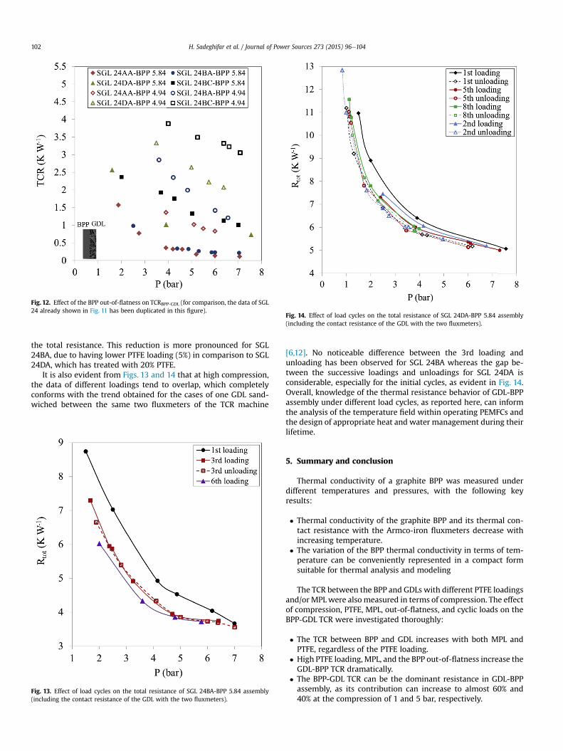
Fig. 14. Effect of load cycles on the total resistance of SGL 24DA-BPP 5.84 assembly(including the contact resistance of the GDL with the two fluxmeters).
Fig. 12. Effect of the BPP out-of-flatness on TCRBPP-GDL (for comparison, the data of SGL24 already shown in Fig. 11 has been duplicated in this figure).
H. Sadeghifar et al. / Journal of Power Sources 273 (2015) 96e104102
the total resistance. This reduction is more pronounced for SGL24BA, due to having lower PTFE loading (5%) in comparison to SGL24DA, which has treated with 20% PTFE.
It is also evident from Figs. 13 and 14 that at high compression,the data of different loadings tend to overlap, which completelyconforms with the trend obtained for the cases of one GDL sand-wiched between the same two fluxmeters of the TCR machine
Fig. 13. Effect of load cycles on the total resistance of SGL 24BA-BPP 5.84 assembly(including the contact resistance of the GDL with the two fluxmeters).
[6,12]. No noticeable difference between the 3rd loading andunloading has been observed for SGL 24BA whereas the gap be-tween the successive loadings and unloadings for SGL 24DA isconsiderable, especially for the initial cycles, as evident in Fig. 14.Overall, knowledge of the thermal resistance behavior of GDL-BPPassembly under different load cycles, as reported here, can informthe analysis of the temperature field within operating PEMFCs andthe design of appropriate heat and water management during theirlifetime.
5. Summary and conclusion
Thermal conductivity of a graphite BPP was measured underdifferent temperatures and pressures, with the following keyresults:
� Thermal conductivity of the graphite BPP and its thermal con-tact resistance with the Armco-iron fluxmeters decrease withincreasing temperature.
� The variation of the BPP thermal conductivity in terms of tem-perature can be conveniently represented in a compact formsuitable for thermal analysis and modeling
The TCR between the BPP and GDLs with different PTFE loadingsand/or MPLwere alsomeasured in terms of compression. The effectof compression, PTFE, MPL, out-of-flatness, and cyclic loads on theBPP-GDL TCR were investigated thoroughly:
� The TCR between BPP and GDL increases with both MPL andPTFE, regardless of the PTFE loading.
� High PTFE loading, MPL, and the BPP out-of-flatness increase theGDL-BPP TCR dramatically.
� The BPP-GDL TCR can be the dominant resistance in GDL-BPPassembly, as its contribution can increase to almost 60% and40% at the compression of 1 and 5 bar, respectively.
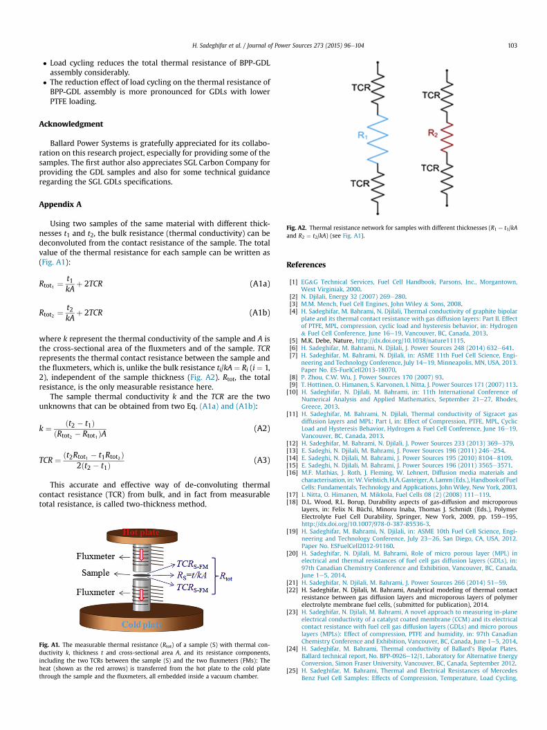
Fig. A2. Thermal resistance network for samples with different thicknesses (R1 ¼ t1/kAand R2 ¼ t2/kA) (see Fig. A1).
H. Sadeghifar et al. / Journal of Power Sources 273 (2015) 96e104 103
� Load cycling reduces the total thermal resistance of BPP-GDLassembly considerably.
� The reduction effect of load cycling on the thermal resistance ofBPP-GDL assembly is more pronounced for GDLs with lowerPTFE loading.
Acknowledgment
Ballard Power Systems is gratefully appreciated for its collabo-ration on this research project, especially for providing some of thesamples. The first author also appreciates SGL Carbon Company forproviding the GDL samples and also for some technical guidanceregarding the SGL GDLs specifications.
Appendix A
Using two samples of the same material with different thick-nesses t1 and t2, the bulk resistance (thermal conductivity) can bedeconvoluted from the contact resistance of the sample. The totalvalue of the thermal resistance for each sample can be written as(Fig. A1):
Rtot1 ¼t1kA
þ 2TCR (A1a)
Rtot2 ¼t2kA
þ 2TCR (A1b)
where k represent the thermal conductivity of the sample and A isthe cross-sectional area of the fluxmeters and of the sample. TCRrepresents the thermal contact resistance between the sample andthe fluxmeters, which is, unlike the bulk resistance ti/kA ¼ Ri (i ¼ 1,2), independent of the sample thickness (Fig. A2). Rtot, the totalresistance, is the only measurable resistance here.
The sample thermal conductivity k and the TCR are the twounknowns that can be obtained from two Eq. (A1a) and (A1b):
k ¼ ðt2 � t1ÞðRtot2 � Rtot1ÞA
(A2)
TCR ¼ ðt2Rtot1 � t1Rtot2Þ2ðt2 � t1Þ
(A3)
This accurate and effective way of de-convoluting thermalcontact resistance (TCR) from bulk, and in fact from measurabletotal resistance, is called two-thickness method.
Fig. A1. The measurable thermal resistance (Rtot) of a sample (S) with thermal con-ductivity k, thickness t and cross-sectional area A, and its resistance components,including the two TCRs between the sample (S) and the two fluxmeters (FMs): Theheat (shown as the red arrows) is transferred from the hot plate to the cold platethrough the sample and the fluxmeters, all embedded inside a vacuum chamber.
References
[1] EG&G Technical Services, Fuel Cell Handbook, Parsons, Inc., Morgantown,West Virginiak, 2000.
[2] N. Djilali, Energy 32 (2007) 269e280.[3] M.M. Mench, Fuel Cell Engines, John Wiley & Sons, 2008.[4] H. Sadeghifar, M. Bahrami, N. Djilali, Thermal conductivity of graphite bipolar
plate and its thermal contact resistance with gas diffusion layers: Part II. Effectof PTFE, MPL, compression, cyclic load and hysteresis behavior, in: Hydrogen& Fuel Cell Conference, June 16e19, Vancouver, BC, Canada, 2013.
[5] M.K. Debe, Nature, http://dx.doi.org/10.1038/nature11115.[6] H. Sadeghifar, M. Bahrami, N. Djilali, J. Power Sources 248 (2014) 632e641.[7] H. Sadeghifar, M. Bahrami, N. Djilali, in: ASME 11th Fuel Cell Science, Engi-
neering and Technology Conference, July 14e19, Minneapolis, MN, USA, 2013.Paper No. ES-FuelCell2013-18070.
[8] P. Zhou, C.W. Wu, J. Power Sources 170 (2007) 93.[9] T. Hottinen, O. Himanen, S. Karvonen, I. Nitta, J. Power Sources 171 (2007) 113.
[10] H. Sadeghifar, N. Djilali, M. Bahrami, in: 11th International Conference ofNumerical Analysis and Applied Mathematics, September 21e27, Rhodes,Greece, 2013.
[11] H. Sadeghifar, M. Bahrami, N. Djilali, Thermal conductivity of Sigracet gasdiffusion layers and MPL: Part I, in: Effect of Compression, PTFE, MPL, CyclicLoad and Hysteresis Behavior, Hydrogen & Fuel Cell Conference, June 16e19,Vancouver, BC, Canada, 2013.
[12] H. Sadeghifar, M. Bahrami, N. Djilali, J. Power Sources 233 (2013) 369e379.[13] E. Sadeghi, N. Djilali, M. Bahrami, J. Power Sources 196 (2011) 246e254.[14] E. Sadeghi, N. Djilali, M. Bahrami, J. Power Sources 195 (2010) 8104e8109.[15] E. Sadeghi, N. Djilali, M. Bahrami, J. Power Sources 196 (2011) 3565e3571.[16] M.F. Mathias, J. Roth, J. Fleming, W. Lehnert, Diffusion media materials and
characterisation, in:W.Vielstich,H.A.Gasteiger,A. Lamm(Eds.),Handbookof FuelCells: Fundamentals, Technology and Applications, JohnWiley, New York, 2003.
[17] I. Nitta, O. Himanen, M. Mikkola, Fuel Cells 08 (2) (2008) 111e119.[18] D.L. Wood, R.L. Borup, Durability aspects of gas-diffusion and microporous
layers, in: Felix N. Büchi, Minoru Inaba, Thomas J. Schmidt (Eds.), PolymerElectrolyte Fuel Cell Durability, Springer, New York, 2009, pp. 159e195,http://dx.doi.org/10.1007/978-0-387-85536-3.
[19] H. Sadeghifar, M. Bahrami, N. Djilali, in: ASME 10th Fuel Cell Science, Engi-neering and Technology Conference, July 23e26, San Diego, CA, USA, 2012.Paper No. ESFuelCell2012-91160.
[20] H. Sadeghifar, N. Djilali, M. Bahrami, Role of micro porous layer (MPL) inelectrical and thermal resistances of fuel cell gas diffusion layers (GDLs), in:97th Canadian Chemistry Conference and Exhibition, Vancouver, BC, Canada,June 1e5, 2014.
[21] H. Sadeghifar, N. Djilali, M. Bahrami, J. Power Sources 266 (2014) 51e59.[22] H. Sadeghifar, N. Djilali, M. Bahrami, Analytical modeling of thermal contact
resistance between gas diffusion layers and microporous layers of polymerelectrolyte membrane fuel cells, (submitted for publication), 2014.
[23] H. Sadeghifar, N. Djilali, M. Bahrami, A novel approach to measuring in-planeelectrical conductivity of a catalyst coated membrane (CCM) and its electricalcontact resistance with fuel cell gas diffusion layers (GDLs) and micro porouslayers (MPLs): Effect of compression, PTFE and humidity, in: 97th CanadianChemistry Conference and Exhibition, Vancouver, BC, Canada, June 1e5, 2014.
[24] H. Sadeghifar, M. Bahrami, Thermal conductivity of Ballard's Bipolar Plates,Ballard technical report, No. BPP-0926e12/1, Laboratory for Alternative EnergyConversion, Simon Fraser University, Vancouver, BC, Canada, September 2012.
[25] H. Sadeghifar, M. Bahrami, Thermal and Electrical Resistances of MercedesBenz Fuel Cell Samples: Effects of Compression, Temperature, Load Cycling,
H. Sadeghifar et al. / Journal of Power Sources 273 (2015) 96e104104
and Assembly, Mercedes Benz Fuel Cell (MBFC) technical report, No.MEAGDLCCM-1030e13/1, Laboratory for Alternative Energy Conversion,Simon Fraser University, Vancouver, BC, Canada, October 2013.
[26] ASTM Standard C-177, Standard Test Method for Steady-state Heat FluxMeasurements and Thermal Transmission Properties by Means of theGuarded Hot-plate Apparatus, ASTM International, Conshohocken, PA, 1985.
[27] SGL Group e The Carbon Company. SIGRACET Diffusion Media, ManufactureData Sheet. Web: http://www.sglgroup.com/cms/international/home.
[28] N. Furuya, N. Mineo, J. New. Mater. Electrochem. Syst. 10 (2007) 205e208.[29] J.D. Sole, Investigation of Novel Gas Diffusion Media for Application in PEM
Fuel Cell Ribbon Assemblies, M.S. thesis, Virginia Polytechnic Institute andState University, USA, 2005.
[30] M.M. Mench, E.C. Kumbur, T. Nejat Veziro glu (Eds.), Polymer Electrolyte FuelCell Degradation, Academic Press (Elsevier), MA, USA, 2012.
[31] X.L. Wang, H.M. Zhang, J.L. Zhang, H.F. Xu, Z.Q. Tian, J. Chena, H.X. Zhong,Y.M. Liang, B.L. Yi, Electrochim. Acta 51 (2006) 4909e4915.
[32] D. Bi, H. Chen, T. Ye, Cryogenics 52 (2012) 403e409.[33] M.M. Yovanovich, W.M. Rohsenow, Influence of Surface Roughness and
Waviness upon Thermal Contact Resistance, Technical Report No. 6361e48,Contract No. Nas T-100, Massachusetts Institute of Technology, USA, 1967.
[34] S. Sunil Kumar, K. Ramamurthi, ASME J. Heat Transf. 125 (2003) 394e402.
Nomenclature
AA,BA,DA,BC: different types of Sigracet GDLs (0,5,20, 5(& MPL on one side) %PTFE,respectively)
BPP: bipolar plateGDL: gas diffusion layerk: thermal conductivity, W m�1 K�1
MPL: micro porous layerP: compression, bar or kPaPEMFC: polymer electrolyte membrane fuel cellPTFE: polytetrafluoroethyleneR: thermal resistance, KW�1
SGL: SigracetT: temperature, �C or KTCR: thermal contact resistancewt%: weight percent
Subscript
BPP: bipolar plateFM: fluxmeterGDL: gas diffusion layerMPL: micro porous layerSGL: SigracetSGL_BA: Sigracet GDLs of type BASGL_BC: Sigracet GDLs of type BCsub: substrate of GDLs containing MPLtot: total


![Physical and Electrochemical Characterization of Modified Graphite … · 2020. 9. 11. · electrode showed a greater conductivity and sensitivity compared with bare GCE [28]. In](https://img.pdfslide.us/doc/110x75/60a43bbb61b7a31db30e17df/physical-and-electrochemical-characterization-of-modified-graphite-2020-9-11.jpg)