Embed Size (px)
Citation preview

Melt processed multiphase ceramic waste forms for nuclear wasteimmobilization
Jake Amoroso a,⇑, James C. Marra a, Ming Tang b, Ye Lin c, Fanglin Chen c, Dong Su d, Kyle S. Brinkman e
a Savannah River National Laboratory, Aiken, SC 29808, USAb Los Alamos National Laboratory, Los Alamos, NM 87545, USAc University of South Carolina, Columbia, SC 29208, USAd Brookhaven National Laboratory, Upton, NY 11973, USAe Clemson University, Clemson, SC 29634, USA
h i g h l i g h t s
!We explored the feasibility of melt processing multiphase titanate-based ceramics.! Melt processing produced phases obtained by alternative processing methods.! Phases incorporated multiple lanthanides and transition metals.! Processing in reducing atmosphere suppressed un-desirable Cs–Mo coupling.! Cr partitions to and stabilizes the hollandite phase, which promotes Cs retention.
a r t i c l e i n f o
Article history:Received 9 April 2014Accepted 17 July 2014Available online 24 July 2014
a b s t r a c t
Ceramic waste forms are promising hosts for nuclear waste immobilization as they have the potential forincreased durability and waste loading compared with conventional borosilicate glass waste forms.Ceramics are generally processed using hot pressing, spark plasma sintering, and conventional solid-statereaction, however such methods can be prohibitively expensive or impractical at production scales.Recently, melt processing has been investigated as an alternative to solid-state sintering methods. Giventhat melter technology is currently in use for High Level Waste (HLW) vitrification in several countries,the technology readiness of melt processing appears to be advantageous over sintering methods. Thiswork reports the development of candidate multi-phase ceramic compositions processed from a melt.Cr additions, developed to promote the formation and stability of a Cs containing hollandite phase weresuccessfully incorporated into melt processed multi-phase ceramics. Control of the reduction–oxidation(Redox) conditions suppressed undesirable Cs–Mo containing phases, and additions of Al and Fe reducedthe melting temperature.
! 2014 Published by Elsevier B.V.
1. Introduction
Waste treatment technologies are an integral component to TheUnited States Department of Energy (DOE) Fuel Cycle Research andDevelopment (FCR&D) program. Successful waste treatment andstorage are necessary to support next-generation nuclear energydevelopment. A single waste form that can host all the waste ele-ments in the projected aqueous reprocessing High-Level Waste(HLW) is most desirable [1].
The traditional method for HLW immobilization is to form boro-silicate glass by a vitrification process, a practice currently used for
defense and commercial waste [2]. Durable ceramic waste formsthat incorporate a wide range of radionuclides have the potentialto broaden the available disposal options and to lower the storageand disposal costs associated with advanced fuel cycles. Ceramicwaste forms are tailored (engineered) to incorporate waste compo-nents as part of their crystal structure based on knowledge fromnaturally found minerals containing radioactive and non-radioac-tive species similar to the radionuclides of concern in wastes fromfuel reprocessing. The ability to tailor ceramics to mimic naturallyoccurring crystals substantiates the long term stability of suchcrystals (ceramics) over geologic timescales of interest for nuclearwaste immobilization [3].
Multiphase ceramics targeting an assemblage of titanate-basedphases have been successfully demonstrated to incorporate
http://dx.doi.org/10.1016/j.jnucmat.2014.07.0350022-3115/! 2014 Published by Elsevier B.V.
⇑ Corresponding author. Tel.: +1 803 819 4727.E-mail address: [email protected] (J. Amoroso).
Journal of Nuclear Materials 454 (2014) 12–21
Contents lists available at ScienceDirect
Journal of Nuclear Materials
journal homepage: www.elsevier .com/locate / jnucmat

various radioactive waste elements into a number of crystallinephases. Most notable are the synthetic rock (SYNROC) family ofminerals developed in the 1980s that have been primarily pro-duced by hot-pressing [4,5]. Melt processing of waste forms is con-sidered advantageous over the conventional solid-state synthesismethods given that melters are currently in use for HLW vitrifica-tion in several countries, greatly facilitating the technology readi-ness of ceramic waste forms, and melter technology can reducethe potential for airborne contamination during pretreatment ascompared to processes involving extensive powder handlingoperations.
There have been several comparative studies of crystalline cera-mic waste forms produced by hot pressing and inductive melting[6,7]. These prior studies have indicated that the specimens fabri-cated by melt processing and solid state sintering exhibited similarmineral compositions, with the exception of a water-solublemolybdate phase observed in melt processing Mo containing wastestreams in air. Under oxidizing processing conditions, attempts tomake single phase hollandite (the host phase for Cs) ceramics aredifficult and more often results in secondary metastable Cs con-taining phases [8]. It has been demonstrated that these secondaryphases can be suppressed by controlling the starting compositionsand the Ti3+/Ti4+ during processing. Metal powder (Ti) additions tothe batch material or hot pressing in graphite have been shown tobe effective methods for controlling the redox conditions duringsintering [9,10].
A major objective of the present work was aimed at varying thecomposition and processing conditions in order to mitigate Cs–Momolybdate phase formation. In addition, there was particular inter-est regarding the characteristics of phase formation and elementalpartitioning in melt processed ceramic composites. The intent ofthis work is to demonstrate the feasibility of melt processing tech-nology to produce multiphase waste forms with phase composi-tion comparable to conventional methods.
2. Composition development
2.1. Projected waste composition
The waste composition that formed the basis for the develop-ment and testing is given in Table 1. Noble metals, minor actinidesand Tc were removed for cost and handling reasons. The MoO3 tar-geted in this work was based on one possible reprocessing flow-sheet, but other variants exist and more will be developed basedin part on waste form studies such as this. Because this work incor-porated varying Redox conditions and previous results indicatedlarge concentrations of MoO3 inhibited desired phase formation
under oxidizing conditions, the MoO3 concentration was targetedat 3 wt.% to simplify comparison among samples.
2.2. Single phase hollandite
Hollandite-type structures are a promising crystalline host forCs, one of the more problematic fission products to immobilize.Melt processed single phase Cs-containing hollandite ceramicswith Cr additions of the form Ba1.0Cs0.3A2.3Ti5.7O16 (A = Cr, Fe, Al)were developed precursory to this work. Durability studies indi-cated that Cr additions increased Cs retention and suppressed sec-ondary phase formation compared to Fe-hollandite analogs.Processing in various redox conditions affected the phase purityof Fe-containing hollandites whereas had negligible effect on theresulting phase purity in the Cr-containing hollandites. X-rayabsorption spectroscopy confirmed the relative stability of Cr3+
as compared to Fe3+ in various redox conditions. It is speculatedthat Cr helps to stabilize the hollandite phase during formingwhich in turn promotes Cs incorporation into the hollandite [9].Hollandite compositions with Cr additions are considered a prom-ising phase for Cs-immobilization and served as the basis for multi-phase ceramic waste form compositions presented in this work.
2.3. Calculation of multi phase waste form compositions
In this work, optimized single phase hollandite compositionsbased on Cr and Cr/Al/Fe additions were incorporated into multi-phase ceramics targeting hollandite, perovskite/pyrochlore andzirconolite phase assemblages. The phase assemblages weredesigned based on combinations of the waste and additives (theprimary additive being TiO2) to target the desired phases (i.e. hol-landite, perovskite/pyrochlore and zirconolite) upon melting. Liter-ature data and valence state were used to predict which phaseseach element would partition to. Specifically, elements with a +3or +2 valance with titania form pyrochlore and perovskite typestructures resulting in (A+2)TiO3 and (A3+)2Ti2O7 type phases[11,12]. Zirconium has been demonstrated to partition to a CaZrTi2-
O7 zirconolite phase [13]. The Cs and Rb elements are known topartition to a hollandite structure based on the general formulaBaxCsyMzTi4+
8"zO16 where M = metal cation and z = 2x + y for trivalentcations and z = x + y/2 for divalent cations for charge compensation[8,14,15].
The waste and additive calculations were based on combiningoxide and carbonate powders, as described in Section 3.1.1. Table 2summarizes the two multiphase compositions (based on Cr and Cr/Al/Fe additions) that were prepared for this work, each with#25 weight% waste loading and varying additive concentrations.Cr-MP denotes a multiphase assemblage targeting the Cr-hollan-dite analog and CAF-MP denotes a multiphase assemblage target-ing the Cr/Al/Fe-hollandite analog. The batch oxide componentsin wt.% percent and associated target phase are listed in Table 3for both multiphase compositions.
Table 1Projected and re-normalized waste composition targeted in this study.
Group Fuela SRNLb Fuelc
Alkali 7.6 13.4 9.6Alkaline Earth 8.3 12.9 10.6Lanthanides 33.1 51.8 42.0Actinides 4.0 – –Noble Metals 14.6 – –MoO3 13.7 3.4 17.4ZrO2 13.7 12.1 17.4TcO2 2.7 – –Others 2.4 6.3 3.0Total 100 100 100
a Projection.b Does not include corrosion and process products.c Renormalized to exclude corrosion and process products.
Table 2Additive and waste concentrations (wt.%) used in this study.
Component Target phase CAF-MP Cr-MP
Waste Various 24.66 24.58Al2O3 Hollandite 1.27 0TiO2 Various 49.16 49.01CaO Zirconolite 1.39 1.38BaO Hollandite 10.56 10.52Fe2O3 Hollandite 6.65 0Cr2O3 Hollandite 6.33 14.5
J. Amoroso et al. / Journal of Nuclear Materials 454 (2014) 12–21 13

3. Experimental
3.1. Fabrication and melt processing
3.1.1. Batch preparationFor each batch, stoichiometric amounts of reagent-grade oxide
and carbonate powders (99.5% purity to make 100 g of final mate-rial were combined in a 500 ml plastic bottle with zirconia millingmedia, filled 2/3 full with deionized water, and agitated in a tum-bler mixer for 1 h. Subsequently, the slurry was poured into a panalong with additional rinse water used to collect any batch mate-rial remaining on the milling media and bottles. The pan was trans-ferred to an oven where the slurry was dried for several days at90 "C. The dried material was bagged and used as feed stock forsynthesis experiments.
3.1.2. Melt processingApproximately 20 g samples feed stock was placed loosely into
a covered alumina crucible. Samples were heated at approximately15 K/min, held at 1500 "C for 20 min, and furnace cooled (poweredoff furnace). Estimated cooling rates were initially 60 K/min buthad reduced to 15 K/min by approximately 1200 "C. The sampleswere heated in air and in 1% H2 (99% Ar) reducing atmosphere. Timetal and TiO2 additions were made to some batches prior to syn-thesis. For those samples, mixtures of 2.0 wt.% Ti metal and7.0 wt.% TiO2 were weighed in an inert glove box and manuallymixed into each batch prior to melting. Table 4 summarizes theexperimental matrix including TiO2 additions and processingconditions.
3.2. Characterization
3.2.1. Phase identification and microstructureSamples were characterized with X-ray diffraction (XRD, D8
Advance, Bruker AXS Inc., Madison, WI) to identify the resultingphase(s). Portions of each sample were initially ground in an auto-matic Spex mill for 4 min. Subsequently, the powders were handground with an agate mortar and pestle in alcohol and mountedto a glass slide using a collodion/Amyl Acetate solution. The XRD
patterns were collected at a 0.02" stepped scan from 5" to 70" 2hat a scan rate of 1 s/step.
Scanning Electron Microscopy (SEM) and Energy DispersiveSpectroscopy (EDS) measurements were performed on all samplesat the Savannah River National Laboratory (SRNL) with a HitachiTM3000 SEM. Microstructure and chemical composition ofselected samples were investigated on a Hitachi HD2700C Scan-ning Tunneling Electron Microscope (STEM) instrument equippedwith EDS. STEM samples were firstly sectioned with a diamondsaw to 0.5 mm thickness. Subsequently, circular disks were cutfrom each sample using an ultrasonic disk cutter, and smooth diskfaces were obtained after polishing using 60–1000 grit grindingpaper. A conventional dimpling process was performed using aGatan dimpler 626 and the final sample thickness reduction to lessthan 10 nm was accomplished by ion milling using a FischioneModel 1010 instrument. STEM-EDS mapping of Cs, Ba, Mo, Zr, Cr,Al, Fe, Nd, Ca, La, Ce, and Ti was performed.
3.2.2. Chemical compositionInductively Coupled Plasma-Mass Spectroscopy (ICP-MS) was
used to measure Cs concentrations and Inductively CoupledPlasma-Atomic Emission Spectroscopy (ICP-AES) was used to mea-sure all other elemental concentrations as Cs cannot be measuredby ICP-AES. A representative amount from each sample was pre-pared via a sodium peroxide fusion (PF) method for cation mea-surements – since typical lithium-metaborate fusion (LM) wasnot sufficient to dissolve the high concentrations of TiO2 andCr2O3. Each sample was prepared in duplicate. Prepared sampleswere analyzed twice for each element of interest by ICP, with theinstrumentation being re-calibrated between the duplicate analy-ses. Glass standards were also intermittently measured to ensurethe performance of the ICP-AES instrument over the course ofthe analyses. The measured cation concentrations were convertedto their respective oxide to obtain a wt.% of each component oxide.
The Fe2+/Fe3+ and Fe2+/Fe (total) ratios were determined from anabsorption method using a UV–Vis spectrometer. Samples weredissolved in a sulfuric–hydrofluoric acid mixture, containingammonium vanadate to preserve the Fe2+ content. Boric acid wasadded to destroy iron–fluoride complexes and ferrozine was added
Table 3Target composition of multiphase melt samples; weight percent of oxide component.
Oxide Target wt.% Target phase
CAF-MP Cr-MP
Al2O3 1.27 0.00 Cs-Hollandite (BaxCsy)(Ti,Al)3+2 x+y(Ti4+
8"2x"y)O16
BaO 12.76 12.72 Cs-Hollandite (BaxCsy)(Ti,Al)3+2 x+y(Ti4+
8"2x"y)O16
CaO 1.39 1.38 (4+) Zirconolite CaZrTi2O7
Cr2O3 6.33 14.50 Cs-Hollandite (BaxCsy)(Ti,Al)3+2 x+y(Ti4+
8"2x"y)O16
CdO 0.11 0.11 –Ce2O3 3.10 3.09 (2+/3+) Titanate (i.e. perovskite/pyrochlore) (A2+)TiO3; (A3+)2Ti2O7
Cs2O 2.88 2.87 (2+/3+) Titanate (i.e. perovskite/pyrochlore) (A2+)TiO3; (A3+)2Ti2O7
Eu2O3 0.17 0.17 (2+/3+) Titanate (i.e. perovskite/pyrochlore) (A2+)TiO3; (A3+)2Ti2O7
Fe2O3 6.65 0.00 Cs-Hollandite (BaxCsy)(Ti,Al)3+2 x+y(Ti4+
8"2x"y)O16
Gd2O3 0.16 0.16 (2+/3+) Titanate (i.e. perovskite/pyrochlore) (A2+)TiO3; (A3+)2Ti2O7
La2O3 1.58 1.58 (2+/3+) Titanate (i.e. perovskite/pyrochlore) (A2+)TiO3; (A3+)2Ti2O7
MoO3 0.85 0.84 –Nd2O3 5.23 5.22 (2+/3+) Titanate (i.e. Perovskite/pyrochlore) (A2+)TiO3; (A3+)2Ti2O7
Pr2O3 1.45 1.44 (2+/3+) Titanate (i.e. perovskite/pyrochlore) (A2+)TiO3; (A3+)2Ti2O7
Rb2O 0.42 0.42 Cs-Hollandite (BaxCsy)(Ti,Al)3+2 x+y(Ti4+
8"2x"y)O16
SeO2 0.08 0.08 –Sm2O3 1.08 1.07 (2+/3+) Titanate (i.e. perovskite/pyrochlore) (A2+)TiO3; (A3+)2Ti2O7
SnO2 0.07 0.07 (4+) Zirconolite CaZrTi2O7
SrO 0.98 0.98 (2+/3+) Titanate (i.e. perovskite/pyrochlore) (A2+)TiO3; (A3+)2Ti2O7
TeO2 0.66 0.65 –TiO2 49.16 49.01 VariousY2O3 0.63 0.63 (2+/3+) Titanate (i.e. perovskite/pyrochlore) (A2+)TiO3; (A3+)2Ti2O7
ZrO2 2.99 2.98 (4+) Zirconolite CaZrTi2O7
14 J. Amoroso et al. / Journal of Nuclear Materials 454 (2014) 12–21

to form ferrous–ferrozine complexes for the determination of Fe2+
content. An additional measurement with ascorbic acid addition toreduce Fe3+ to Fe2+ with a second absorbance measurement wasused to determine total Fe [16].
4. Results and discussion
4.1. Processing
In general, the compositions targeting a Cr-hollandite majorphase reacted (solid-state) but exhibited minimal bulk melting.Instead, these samples resembled consolidated powder compactsthat were easily removed from the crucible by hand. The composi-tions targeting a Cr/Al/Fe-hollandite major phase exhibited meltingand crystallization as evidenced by visible signs of flowing andadhesion to the crucible. Although high purity (99.99%) aluminacrucibles were considered suitable for the melt processing studiesin this work, the Cr/Al/Fe compositions reacted with the aluminacrucibles. Other refractory crucibles would likely react as well, per-haps to a greater extent depending on the material, and it was notdesirable to use precious metal crucibles that alloy under reducingconditions. Furthermore, although the effect of alumina impurity
on phase formation and processing in the studied compositionswas not an objective of this research, aluminum is a reprocessingcontaminant, and the results indicate that alumina impurity fromthe crucible was not detrimental to bulk phase formation.
4.2. Chemical composition
Calculated oxide compositions based on measured elementalconcentrations are summarized in Table 5. Standard oxidationstates for elements except Fe were assumed in all samples. Fe2+
and Fe3+ concentrations were determined from redox measure-ments for the Cr/Al/Fe samples. Fe2+/Fe total fractions are listedin Table 6 for the Cr/Al/Fe samples and were assumed to be thesame in the Cr samples for calculations. The Fe redox measure-ments confirmed the amount of Fe2+ increased with increasingreduction potential during processing. Target concentrations forsamples to which Ti/TiO2 was added assumed all Ti reacted to formTiO2. In actuality, several Ti valence states are expected. The mea-sured compositions were in good agreement with the target (nom-inal) compositions with the exception of excess Al and low Csconcentrations in all samples. Approximately 2x–5x excess Alwas measured than targeted and was attributed to reactions withthe Al2O3 crucibles as noted previously. Approximately 50–90 wt.%of the targeted Cs was retained. The low Cs concentration wasattributed to the high volatility of Cs at the processing tempera-tures and is in agreement with previous work [17].
Table 4Experimental matrix and processing conditions.
Composition IDa TiO2 buffer Atmosphere Sample-ID
Cr-MP No Air Cr-MP1% H2 Cr-MP-R
Yes Air Cr-MP-Ti1% H2 Cr-MP-R-Ti
CAF-MP No Air CAF-MP1% H2 CAF-MP-R
Yes Air CAF-MP-Ti1% H2 CAF-MP-R-Ti
a ‘‘Cr-. . .’’ targeted Ba1.0Cs0.3Cr2.3Ti5.7O16 hollandite; ‘‘CAF-. . .’’ targeted Ba1.0-
Cs0.3Cr1.0Al0.3Fe1.0Ti5.7O16 hollandite.
Table 5Elemental concentrations (note, compositions are not renormalized for Ti/TiO2 additions).
Oxide Cr-MP processing conditions CAF-MP processing conditions
Target (g) Air 1% H2 Target (g) Air w/Ti–TiO2 1% H2 w/Ti–TiO2 Target (g) Air 1% H2 Target (g) Air w/Ti–TiO2 1% H2 w/Ti–TiO2
Al2O3 0 0.28 0.34 0.00 0.35 0.43 1.27 3.57 7.25 1.15 2.37 10.4BaO 12.72 12.8 12.8 11.53 11.2 11.3 12.76 12.4 12.4 11.6 10.9 10.6CaO 1.38 1.60 1.48 1.25 1.35 1.53 1.39 1.37 1.29 1.26 1.27 0.85CdO 0.11 0.00 0.00 0.10 0.00 0.00 0.11 0.00 0.00 0.10 0.00 0.00Ce2O3 3.09 3.45 3.30 2.80 3.05 3.13 3.1 3.19 3.07 2.81 2.95 2.62Cr2O3 14.5 14.7 14.8 13.15 12.9 13.1 6.33 6.51 7.37 5.74 5.98 5.29Cs2O 2.87 1.73 1.62 2.60 2.23 1.82 2.88 1.77 1.45 2.61 2.53 1.65Eu2O3 0.17 0.19 0.18 0.15 0.17 0.17 0.17 0.17 0.17 0.15 0.16 0.15Fe2O3 0 0.06 0.00 0.00 0.11 0.00 6.65 4.75 0.00 6.03 4.19 0.00FeO 0 0.02 0.08 0.00 0.04 0.07 0 1.52 5.23 0.00 1.41 4.70Gd2O3 0.16 0.18 0.18 0.15 0.16 0.16 0.16 0.16 0.15 0.15 0.15 0.13La2O3 1.58 1.42 1.36 1.43 1.20 1.27 1.58 1.29 1.20 1.43 1.19 1.09MoO3 0.84 0.24 0.30 0.76 0.53 0.30 0.85 0.36 0.32 0.77 0.61 0.26Nd2O3 5.22 5.31 5.07 4.73 4.83 5.04 5.23 4.93 4.81 4.74 4.87 4.19Pr2O3 1.44 1.64 1.55 1.31 1.53 1.47 1.45 1.50 1.45 1.31 1.46 1.25Rb2O 0.42 0.32 0.29 0.38 0.36 0.33 0.42 0.30 0.26 0.38 0.44 0.32SeO2 0.08 0.00 0.00 0.07 0.00 0.00 0.08 0.00 0.00 0.07 0.00 0.00Sm2O3 1.07 1.13 1.10 0.97 1.02 1.05 1.08 1.05 1.01 0.98 0.99 0.80SnO2 0.07 0.00 0.00 0.06 0.00 0.00 0.07 0.00 0.00 0.06 0.00 0.00SrO 0.98 1.09 1.04 0.89 0.98 0.98 0.98 0.99 0.95 0.89 0.94 0.70TeO2 0.65 0.16 0.15 0.59 0.18 0.16 0.66 0.29 0.16 0.60 0.36 0.15TiO2 49.01 50.1 49.3 53.80 53.8 54.1 49.16 47.8 47.1 53.9 53.7 49.0Y2O3 0.63 0.65 0.63 0.57 0.58 0.60 0.63 0.60 0.77 0.57 0.56 0.50ZrO2 2.98 2.98 2.98 2.70 2.63 2.73 2.99 2.77 2.71 2.71 2.52 2.36
Total 100.0 100.1 98.5 100.0 99.2 99.7 100.0 97.3 99.1 100.0 99.5 97.0
Table 6Fe2+/Fe total concentrations in Cr/Al/Fe samples after processing in variousconditions.
Short identifier Fe2+/Fe total Processing conditions
CAF-MPB1A 0.263 AirCAF-MPB1A-Ti 0.272 Air w/Ti–TiO2
CAF-MPB1R All Fe2+ 1% H2
CAF-MPB1R-Ti All Fe2+ 1% H2 w/Ti–TiO2
J. Amoroso et al. / Journal of Nuclear Materials 454 (2014) 12–21 15

In the Cr/Al/Fe samples, excess Al was measured in increasingconcentrations as follows: air ? air w/Ti/TiO2 ? 1%H2 ? 1%H2 w/Ti/TiO2. The increasing Al concentration with increasing Fe2+ con-centration indicates the crucible was a source of Al2O3 impurityand that the reactions with the crucible were competing withhollandite formation. This result can be deduced from FeO–Al2O3
phase diagrams and is supported by XRD data presented in thefollowing section.
Part of this work was intended to evaluate melt processing as asuitable method for incorporating Cs in a hollandite host.
Processing in air with Ti additions appears to increase Cs retentioncompared to the other processing conditions in this study as seenin Table 5. An explanation for this result is that air environmentsproduced fewer varieties of (2+/3+) titanate phases that competefor the Cs compared to the 1% H2 reducing environments, whileat the same time Ti additions that also affect (reduce) the localFe and Ti valence primarily stabilize the hollandite tunnel struc-ture, which promote Cs incorporation in the hollandite phase[9,10]. Both these effects in concert seemingly increase the Csincorporation leaving less Cs available for volatilization.
Fig. 1. XRD patterns for multiphase ceramic compositions processed under varying conditions. The hollandite, perovskite, and pyrochlore phases were primarily identifiedvia one of the three patterns shown. Additional phase were identified and are labeled in individual patterns. (P0) perovskite-type; (Y0) pyrochlore-type; (R) TiO2 – 00-021-1276;(B) Ba7Al2O10 – 00-041-0164; (F) BaFe12O19 – 00-039-1433; (I) FeO – 00-046-1312; (A) Al2O3 – 00-046-1212; (S) Sr3Mo2O7 – 00-052-1252. Unidentified peaks are labeled ‘‘u’’.
16 J. Amoroso et al. / Journal of Nuclear Materials 454 (2014) 12–21
Although Cs retention was not ideal in samples it is importantto note that the low Cs concentrations measured in the as-pro-cessed samples does not preclude melt processing as a viablemethod for several reasons; Cs volatility occurs during other pro-cessing routes and the surface to volume ratio of the samples atthe laboratory scale enhances volatilization effects compared towhat would be expected in a practical process in which much lar-ger volumes would be processed. Furthermore, typical large scalemelt processes employ a cold-cap (not practical in this research)that also enhances volatile species retention.
4.3. X-ray diffraction
Quantitative analysis was not performed because of the com-plexity of the XRD patterns. The terms perovskite and pyrochloreused in this context describe the more general ATiO3 and A2B2O6/A2B2O7 (where A and B are rare-earth and transition metal cations)type compounds, respectively. The structures of those compoundsare highly substitutional, can accommodate multiple cation specieson lattice sites, and depend on the cation species and concentrationin the compound. All of these factors add complexity to the XRDpattern, and indeed many possible 2+/3+ titanate (pyrochlore/perovskite) phases could be identified in the XRD patterns. Forthe purposes of this exploratory study, XRD was used only as agross assessment of the phases. Detailed structure refinementsare needed to fully assess the waste-form which, are outside thescope of this work, but will be pursued in subsequent researchand communicated in due courses.
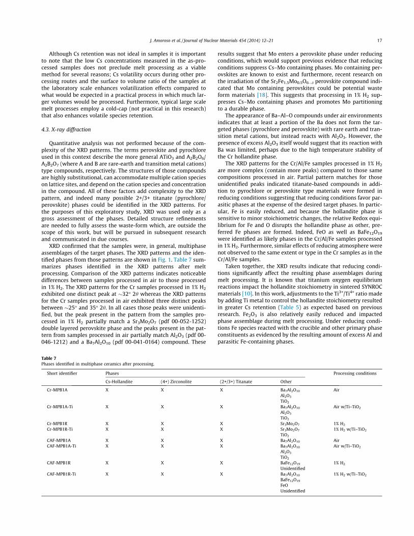
XRD confirmed that the samples were, in general, multiphaseassemblages of the target phases. The XRD patterns and the iden-tified phases from those patterns are shown in Fig. 1. Table 7 sum-marizes phases identified in the XRD patterns after meltprocessing. Comparison of the XRD patterns indicates noticeabledifferences between samples processed in air to those processedin 1% H2. The XRD patterns for the Cr samples processed in 1% H2
exhibited one distinct peak at #32" 2h whereas the XRD patternsfor the Cr samples processed in air exhibited three distinct peaksbetween #25" and 35" 2h. In all cases those peaks were unidenti-fied, but the peak present in the pattern from the samples pro-cessed in 1% H2 partially match a Sr3Mo2O7 (pdf 00-052-1252)double layered perovskite phase and the peaks present in the pat-tern from samples processed in air partially match Al2O3 (pdf 00-046-1212) and a Ba7Al2O10 (pdf 00-041-0164) compound. These
results suggest that Mo enters a perovskite phase under reducingconditions, which would support previous evidence that reducingconditions suppress Cs–Mo containing phases. Mo containing per-ovskites are known to exist and furthermore, recent research onthe irradiation of the Sr2Fe1.5Mo0.5O6"d perovskite compound indi-cated that Mo containing perovskites could be potential wasteform materials [18]. This suggests that processing in 1% H2 sup-presses Cs–Mo containing phases and promotes Mo partitioningto a durable phase.
The appearance of Ba–Al–O compounds under air environmentsindicates that at least a portion of the Ba does not form the tar-geted phases (pyrochlore and perovskite) with rare earth and tran-sition metal cations, but instead reacts with Al2O3. However, thepresence of excess Al2O3 itself would suggest that its reaction withBa was limited, perhaps due to the high temperature stability ofthe Cr hollandite phase.
The XRD patterns for the Cr/Al/Fe samples processed in 1% H2
are more complex (contain more peaks) compared to those samecompositions processed in air. Partial pattern matches for thoseunidentified peaks indicated titanate-based compounds in addi-tion to pyrochlore or perovskite type materials were formed inreducing conditions suggesting that reducing conditions favor par-asitic phases at the expense of the desired target phases. In partic-ular, Fe is easily reduced, and because the hollandite phase issensitive to minor stoichiometric changes, the relative Redox equi-librium for Fe and O disrupts the hollandite phase as other, pre-ferred Fe phases are formed. Indeed, FeO as well as BaFe12O19
were identified as likely phases in the Cr/Al/Fe samples processedin 1% H2. Furthermore, similar effects of reducing atmosphere werenot observed to the same extent or type in the Cr samples as in theCr/Al/Fe samples.
Taken together, the XRD results indicate that reducing condi-tions significantly affect the resulting phase assemblages duringmelt processing. It is known that titanium oxygen equilibriumreactions impact the hollandite stoichiometry in sintered SYNROCmaterials [10]. In this work, adjustments to the Ti3+/Ti4+ ratio madeby adding Ti metal to control the hollandite stoichiometry resultedin greater Cs retention (Table 5) as expected based on previousresearch. Fe2O3 is also relatively easily reduced and impactedphase assemblage during melt processing. Under reducing condi-tions Fe species reacted with the crucible and other primary phaseconstituents as evidenced by the resulting amount of excess Al andparasitic Fe-containing phases.
Table 7Phases identified in multiphase ceramics after processing.
Short identifier Phases Processing conditions
Cs-Hollandite (4+) Zirconolite (2+/3+) Titanate Other
Cr-MPB1A X X X Ba7Al2O10 AirAl2O3
TiO2
Cr-MPB1A-Ti X X X Ba7Al2O10 Air w/Ti–TiO2
Al2O3
TiO2
Cr-MPB1R X X X Sr3Mo2O7 1% H2
Cr-MPB1R-Ti X X X Sr3Mo2O7 1% H2 w/Ti–TiO2
TiO2
CAF-MPB1A X X X Ba7Al2O10 AirCAF-MPB1A-Ti X X X Ba7Al2O10 Air w/Ti–TiO2
Al2O3
TiO2
CAF-MPB1R X X X BaFe12O19 1% H2
UnidentifiedCAF-MPB1R-Ti X X X Ba7Al2O10 1% H2 w/Ti–TiO2
BaFe12O19
FeOUnidentified
J. Amoroso et al. / Journal of Nuclear Materials 454 (2014) 12–21 17

4.4. Electron microscopy
Representative back scattered detector (BSD) SEM images ofeach sample after melt processing are presented in Fig. 2. Similarphases were identified in all samples. General assessments of thephases can be made for the images provided in Fig. 2. The mostabundant mid tone gray corresponds to hollandite phase and thelighter tone gray phase that is also relatively abundant correspondsto pyrochlore and perovskite phases. The darker phases correspondto pores and other minor phases including TiO2 and Al2O3. More
specific phases are identified and labeled in Fig. 3 for the samplesprocessed in 1% H2 with Ti–TiO2 additions. The microstructurespresented in Fig. 3 are higher magnification images representativeof the melt processing process. Overall, the observed microstruc-tures confirm the XRD results as evidenced by characteristic con-trast in the images taken using the BSD mode and semi-quantitative EDS. Excess Al2O3 and TiO2 were also identified inthe Cr/Al/Fe and Cr samples respectively, in agreement with theXRD results and processing conditions. The morphology betweenthe Cr and Cr/Al/Fe samples was also different. The Cr samples
Cr-MP-1%H2 (w/Ti-TiO2)
Cr-MP-1%H2 (No Ti) CAF-MP-1%H2 (No Ti)
CAF-MP-1%H2 (w/Ti-TiO2)
Cr-MP-Air (No Ti)
Cr-MP-Air (w/Ti-TiO2)
CAF-MP-Air (No Ti)
CAF-MP-Air (w/Ti-TiO2)
Fig. 2. Digital SEM images of melt processed multi-phase ceramics.
18 J. Amoroso et al. / Journal of Nuclear Materials 454 (2014) 12–21

exhibited relatively small but dispersed phases whereas the Cr/Al/Fe samples exhibited larger but less dispersed phases in agreementwith the processing observations and the high refractory nature ofthe Cr sample.
The Cr/Al/Fe samples processed with Ti–TiO2 were furtherexamined using STEM-EDS to identify minor phases not observedin XRD or SEM and to probe elemental partitioning within the var-ious phases. Figs. 4 and 5 show select elemental maps taken for the
Cr/Al/Fe samples processed in air and 1% H2, respectively, with Ti–TiO2 additions. Distinct phases are evident in the EDS maps inFigs. 4 and 5 and some elements appeared to partition more sothan others. In those maps, Cr is primarily associated with the hol-landite phase, as would be expected from previous work and XRDresults that indicated the high stability of the Cr-hollandite analog[9]. Zr appeared to be associated with Ca and Nd. Ca likely is asso-ciated with a zirconolite phase and a (A3+)0.4Ca0.4TiO3 perovskite,
1
2
3
4
5
3
4
5
6
Cr-MP-1%H2 (w/Ti-TiO2) CAF-MP-1%H2 (w/Ti-TiO2)
Fig. 3. SEM back scattered detector (BSD) digital images taken of each composition processed in 1%H2 with Ti–TiO2. Labeled phases: (1) Al2O3; (2) FeO (possible); (3)hollandite, (4) zirconolite, (5) perovskite/pyrochlore (A3+
xB2+1"x)TiO3, and (6) rutile.
lAaB
Zr
Cr Fe
Cs
Mo Ca
aLdN
Ti
Fig. 4. STEM-EDS elemental mapping measurements of Cr/Al/Fe multi-phase composition processed in air with Ti–TiO2. (All maps are scaled identically: refer to contrastimage for scale bar (6 lm)).
J. Amoroso et al. / Journal of Nuclear Materials 454 (2014) 12–21 19

both of which were identified in the XRD patterns. Nd may also beassociated with Nd2Zr2O7 phase, a pyrochlore similar to Y2Ti2O7
identified in the XRD patterns. Evidence of a Nd2Zr2O7 phase indi-cates that Zr – rare-earth pyrochlore is viable host for those wasteelements without the needed Ca additions to form zirconolite.
Fe appeared to be concentrated at the hollandite grain bound-aries (compare Cr and Fe maps) in the Cr/Al/Fe sample processedin 1% H2 supporting the XRD data and in agreement with previoussingle-phase hollandite results [9]. Fe, thought to be one of themore reactive and mobile species in the composition, was gener-ally confined to the hollandite phase (compare Cr and Fe maps)in the sample heated in air, but exhibited noticeable concentrationgradients. Similar concentration gradients were observed for Aland Cs, both which are components of the hollandite phase, butnot in the other mapped elements, which further indicates therelative instability of the Cr/Al/Fe hollandite phase.
A major difference between the two collections of maps is thedistribution of Cs and Mo. As already indicated, Cs does not readilypartition exclusively to the Cr/Al/Fe hollandite phase, but reducingatmosphere is known to suppress parasitic phase formation, spe-cifically Cs2MoO4. Although the Mo and Cs appeared to be distrib-uted throughout each sample there was noticeable Cs–Mocontaining phases in the sample heated in air that was notobserved in the sample heated in 1% H2. This indicates that reduc-ing atmosphere is effective in reducing (if not eliminating) Cs–Mocontaining phases. The relative abundance of Mo in the samples
was insufficient to react with all the Cs (assuming Cs2MoO4),according to the sample composition (see Table 5). Cs was alsoobserved in the hollandite phase (see Fig. 4) but, it is unknownto what extent Cs reacts to form Cs2MoO4 versus hollandite. IfMo is the limiting constituent driving Cs reactions, compositionswith greater Mo concentrations would be expected to form moreCs2MoO4 and Cs-deficient hollandite. Overall, La and Ce (notshown) appeared distributed throughout the pyrochlore andperovskite phases.
In general, melt processing produced large-grain microstruc-tures exhibiting compositional variety within individual phases.In contrast, smaller grains with less compositional in-homogeneitywas observed in prior work utilizing sintering techniques [19]. Themicrostructures that developed during melt processing confirmthat relatively rapid mass transport occurred which indicates crys-tal growth from a melt, compared to sintering processes. In thiscase, the melt is a solution (contains elements in addition to thosein the crystal) and as crystallization progressed, it is speculatedthat compositional substitution (variety) developed in the growingphase considering that the target titanate phases are known to besubstitutional hosts capable of accommodating multiple cations. Itis possible that alternative selective crystallization phenomenatake place during melt processing that lead to compositional vari-ety. Nevertheless, the melt processed microstructures presentedare significantly different than sintered microstructures and fur-ther characterization is needed to understand phase evolution
lAaB
Zr
Cr Fe
Cs
Mo Ca
aLdN
Ti
Fig. 5. STEM-EDS elemental mapping measurements of Cr/Al/Fe multi-phase composition processed in 1% H2 with Ti–TiO2. (All maps are scaled identically: refer to contrastimage for scale bar (10 lm)).
20 J. Amoroso et al. / Journal of Nuclear Materials 454 (2014) 12–21

and assemblage during melt processing. Additionally, the largegrain size in melt processed ceramics could have significant impacton radiation damage and product performance, which also needsto be evaluated.
5. Conclusions
This work explored the feasibility of melt processing multi-phase ceramics targeting an assemblage of titanate-based phasesincluding hollandites of the form Ba1.0Cs0.3A2.3Ti5.7O16; A = Cr, Fe,Al. XRD and SEM results indicated that the melt processing methodproduces similar phases obtained by alternative processing meth-ods, namely zirconolite, perovskite, and pyrochlore structures. Theresults indicated highly substituted pyrochlore and perovskitephases incorporating multiple lanthanides and transition metals.Processing in reducing atmosphere appeared to reduce un-desir-able Cs–Mo containing phases, but at the same time promotedthe formation of parasitic phases at the expense of the target hol-landite, pyrochlore, and perovskite phases. This research supportsprevious research demonstrating that Cr preferentially enters thehollandite phase (even in the presence of competing phases).Due to its refractory nature, Cr does not form compounds readilywith Cs and Cr3+ is not easily susceptible to reduction. Cr2O3
appears to stabilize the hollandite phase which in turn promotesCs incorporation.
Acknowledgements
This document was prepared in conjunction with work accom-plished under Contract No. DE-AC09-08SR22470 with the U.S.Department of Energy. TEM was carried out at the Center for Func-tional Nanomaterials, Brookhaven National Laboratory, which issupported by the U.S. Department of Energy, Office of Basic Energy
Sciences, under contract no. DE-AC02-98CH10886. The authorsacknowledge gratefully the financial support of the DOE-NE Mate-rials Recovery and Waste Form Development program includingprogram support from James Bresee, Kimberly Gray, Terry Toddand John Vienna. David Missimer is acknowledged gratefully forprocessing and characterization work.
References
[1] J.V. Crum, L. Turo, B. Riley, M. Tang, A. Kossoy, J. Am. Ceram. Soc. 95 (2012)1297–1303.
[2] J.D. Vienna, Int. J. Appl. Glass Sci. 1 (2010) 309–321.[3] C. Biagioni, P. Orlandi, M. Pasero, Periodico Di Mineralogia 78 (2009) 3–11.[4] A.E. Ringwood, S.E. Kesson, N.G. Ware, W. Hibberson, A. Major, Nature 278
(1979) 219–223.[5] A.E. Ringwood, S.E. Kesson, N.G. Ware, W.O. Hibberson, A. Major, Geochem. J.
13 (1979) 141–165.[6] T. Advocat, G. Leturcq, J. Lacombe, G. Berger, R.A. Day, K. Hart, E. Vernaz, A.
Bonnetier, Mater. Res. Soc. Symp. Proc. 465 (1997) 355–362.[7] I.A. Sobolev, S.V. Stefanovskii, B.I. Omelianenko, S.V. Ioudintsev, E.R. Vance, A.
Jostons, Mater. Res. Soc. Symp. Proc. 465 (1997) 371–378.[8] V. Aubin-Chevaldonnet, D. Caurant, A. Dannoux, D. Gourier, T. Charpentier, L.
Mazerolles, T. Advocat, J. Nucl. Mater. 366 (2007) 137–160.[9] J. Amoroso, J. Marra, S.D. Conradson, M. Tang, K. Brinkman, J. Alloys Compd.
584 (2014) 590–599.[10] S.E. Kesson, Radioactive Waste Manage. Environ. Restor. 4 (1983) 53–72.[11] D.S.D. Gunn, N.L. Allan, H. Foxhall, J.H. Harding, J.A. Purton, W. Smith, M.J.
Stein, I.T. Todorov, K.P. Travis, J. Mater. Chem. 22 (2012) 4675–4680.[12] R. Ubic, I.M. Reaney, W.E. Lee, J. Mater. Res. 14 (1999) 1576–1580.[13] H.F. Xu, Y.F. Wang, J. Nucl. Mater. 279 (2000) 100–106.[14] M.L. Carter, E.R. Vance, H. Li, Mater. Res. Soc. Symp. Proc. 807 (2003) 249–254.[15] M.L. Carter, E.R. Vance, D.R.G. Mitchell, Z. Zhang, Mater. Res. Soc. Sympos. Proc.
824 (2004) CC4.6.1–CC4.6.6.[16] E.W. Baumann, DPST-87-304, Savannah River Laboratory, Aiken, 1987.[17] K. Brinkman, K. Fox, M. Tang, SRNL-STI-2011-00516 (FCRD-SWF-2011-000310,
2011), Savannah River National Laboratory, Aiken, SC; 2011.[18] S. Wang, M. Tang, L. Zhang, G. Xiao, K. Brinkman, F. Chen, J. Alloys Compd. 578
(2013) 170–175.[19] K. Brinkman, J. Amoroso, J. Marra, M. Tang, SRNL-STI-2013-00442, (FCRD-SWF-
2013-000229), Savannah River National Laboratory, Aiken, SC, 2013.
J. Amoroso et al. / Journal of Nuclear Materials 454 (2014) 12–21 21