Embed Size (px)
Citation preview
Journal of Mechanical Engineering Vol SI 5(4), 205-222, 2018
___________________
ISSN 1823- 5514, eISSN 2550-164X Received for review: 2017-04-21
© 2018 Faculty of Mechanical Engineering, Accepted for publication: 2017-09-26
Universiti Teknologi MARA (UiTM), Malaysia. Published: 2018-03-15
Parameters Identification for Weld Quality, Strength and Fatigue Life
Enhancement on HSLA (S460G2+M) using Manual GMAW followed by
HFMI/PIT
Dahia Andud*
University Kuala Lumpur Malaysia France Institute,
Selangor Malaysia
Muhd Faiz Mat, Norridzwan Nordin,
Yupiter HP Manurung
Faculty Mechanical Engineering, Universiti Teknologi
MARA (UiTM) Shah Alam, Selangor, Malaysia
Salina Saidin
Nusantara Technologies Sdn Bhd, Selangor Malaysia
ABSTRACT
This research is aimed to identify suitable parameters in achieving weld
quality, strength and fatigue life enhancement for structural welding. The
investigated material is High Strength Low Alloy Steel S460G2+M commonly
used for harsh environment such as offshore structure or platform. Due to the
extensive use in fabrication industry, the selected welding process is manual
GMAW with filler wire ER80S-Ni1 and shielding gas 80%Ar + 20% CO2.
The research initiates with the determination of suitable welding parameters
such as Current, Voltage, welding speed etc. to attain good quality which
refers to international welding standards AWS D1.1/D1.1M:2015. Further,
the parameters of HFMI/PIT are to be investigated starting with the
comparison of strength between untreated and treated tensile fatigue
specimen. As the final results, the development of a conceptual WPS and
PQR including HFMI/PIT-Procedure as an integrated model with regard to
structural and fatigue life enhancement is presented for production purpose
and for further use on application which is identical to this research.
Keywords: GMAW, HSLA S460G2+M, WPS, Fatigue life, HFMI/PIT
Dahia Andud et. al.
206
Introduction
Identifying appropriate combinations of welding parameters for welding
quality and strength can be a time-consuming process relating to substantial
trial and error method. It begins with preparing the written preliminary weld
procedure specification (pWPS) and followed by the fabrication of weld test
piece that subjected to nondestructive and destructive test such as
radiography and tensile tests. The WPS is established upon the weld
procedure approval certificate signed by authorized person such as welding
engineer and supplemented with the welding procedure qualification record
(WPQR) of the material being welded. In welded joint fabrication, the written
welding procedure specification (WPS) is the 'recipe' for production of a
particular weld quality that compliance with the standard fabrication
requirements such as in AWS D1.1. However, lot of factors such as arc
welding current, arc voltage, welding speed, torch angle, free wire length,
nozzle distance, welding position etc. influenced the depth of penetration,
bead geometry, heat input and the size of heat affected zone (HAZ) as well as
the mechanical properties of the welded steel [12,3]. This sensation
recognized that the WPS not only affect the weld quality but has the utmost
effect on the fatigue life of welded structure. Minor differences in the
welding process and in the weld geometry have a vast impact on the service
life of the product [4,5].
Over the year, many steel structural fabricators basically produce a
WPS solely to meet the requirement of standard used without assimilating the
fatigue improvement technique in the WPS. Probably could be said so far in
literature, discussion on the WPS that integrated with fatigue life
enhancement is almost nonexistent especially for welded structure that
exposed to dynamic loading such as offshore platform and bridges. Probably
the reason behind that is due to minimize the cost of the WPS development. However, welding without any improvement somehow, gives raise the
catastrophic fatigue failure of the welded structure leading to the loss of
many lives. The weld profile is greatly dependent on the continuous
development of welding techniques and production quality control especially
when it is exposed to local stress concentration, residual stresses and different
types of defects. These features as combining with high cyclic and complex
service loading that will eventually initiate a trivial crack that finally cause to
fatigue failure of the welded joint [6]. Recently new technology has been
introduced by PITEC called High Frequency Mechanical Impact/ Pneumatic
Impact Treatment (HFMI/PIT) to enhance the fatigue life of the welded
structure as shown in Figure 1. It is a tool that user-friendly, effective and
reliable method for post-weld fatigue strength improvement technique on
welded structures.
Parameters Identification for Weld Quality.
207
Figure 1: Complete equipment set of HFMI/PIT
The HFMI/PIT treatment procedures, quality control measure and fatigue
strength improvement assessment are now available in IIW recommendations
for the HFMI/PIT treatment. It is applicable to steel structure of plate
thicknesses of 5 to 50 mm and for yield strengths ranging from 235 to 960
MPa [7,8]. HFMI/PIT advantages are not only in the application for fatigue
strength improvement but also for mitigating the weld induced distortion [9],
simple maintenance concept, “slim” design and design optimization [10]. The
industrial applications of HFMI/PIT include: Innovative maintenance in steel
manufacturer, Steel bridge, Tower of wind energy plant, Duplex mixer shaft,
Crane manufacturer, Compressor damper, Component of Press Machine,
Steam boiler, Turbine housing, Crane Structure, Ship building, Mass Rapid
Transit (MRT) and Roller shaft maintenance. Nevertheless, HFMI/PIT is also
capable to be applied at atmospheric and in underwater condition.
Numerous studies on HFMI/PIT treatment have been published
during the past decade. Leitner et al. [11] investigated the local fatigue
strength of welded and HFMI/PIT post-treated high-strength steel joints of
steels S690 and S960, and compared with common construction steel S355.
They concluded that HFMI/PIT post-treatment led to a significant fatigue
enhancement especially in the high-cycle fatigue region due to a shift of the
transition knee point (Nk) to lower load-cycles. In another study [12] on the
butt joint and T joint with transverse and longitudinal attachment, they found
that the butt joint treated with HFMI/PIT achieved fatigue life almost similar
to the fatigue strength of base metal, the T-joint Transition knee point (Nk)
shifts to a lower number of load cycles implying a significant increase in
endurable strength limit, while the longitudinal attachment HFMI/PIT treated
shows an increase of the slope k in the low-cycle fatigue regime. Another
research [13] on investigation of the crack propagation of the welded
structure of the carbon steel S355 and rehabilitate its using post treatment
HFMI/PIT. After the fatigue test, they found the fatigue life of the specimen
has a good agreement with the previous investigation.
Several prominent university in European countries also witnessed
that the HFMI/PIT is effective method to improve the fatigue life of welded
structure. At Belgian Welding Institute (BWI), an extensive
Dahia Andud et. al.
208
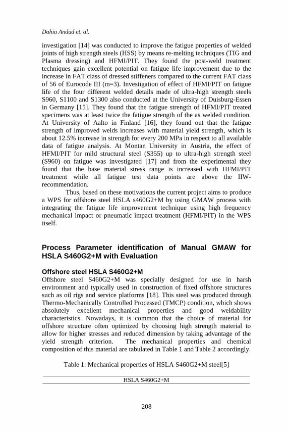
investigation [14] was conducted to improve the fatigue properties of welded
joints of high strength steels (HSS) by means re-melting techniques (TIG and
Plasma dressing) and HFMI/PIT. They found the post-weld treatment
techniques gain excellent potential on fatigue life improvement due to the
increase in FAT class of dressed stiffeners compared to the current FAT class
of 56 of Eurocode III (m=3). Investigation of effect of HFMI/PIT on fatigue
life of the four different welded details made of ultra-high strength steels
S960, S1100 and S1300 also conducted at the University of Duisburg-Essen
in Germany [15]. They found that the fatigue strength of HFMI/PIT treated
specimens was at least twice the fatigue strength of the as welded condition.
At University of Aalto in Finland [16], they found out that the fatigue
strength of improved welds increases with material yield strength, which is
about 12.5% increase in strength for every 200 MPa in respect to all available
data of fatigue analysis. At Montan University in Austria, the effect of
HFMI/PIT for mild structural steel (S355) up to ultra-high strength steel
(S960) on fatigue was investigated [17] and from the experimental they
found that the base material stress range is increased with HFMI/PIT
treatment while all fatigue test data points are above the IIW-
recommendation.
Thus, based on these motivations the current project aims to produce
a WPS for offshore steel HSLA s460G2+M by using GMAW process with
integrating the fatigue life improvement technique using high frequency
mechanical impact or pneumatic impact treatment (HFMI/PIT) in the WPS
itself.
Process Parameter identification of Manual GMAW for HSLA S460G2+M with Evaluation
Offshore steel HSLA S460G2+M Offshore steel S460G2+M was specially designed for use in harsh
environment and typically used in construction of fixed offshore structures
such as oil rigs and service platforms [18]. This steel was produced through
Thermo-Mechanically Controlled Processed (TMCP) condition, which shows
absolutely excellent mechanical properties and good weldability
characteristics. Nowadays, it is common that the choice of material for
offshore structure often optimized by choosing high strength material to
allow for higher stresses and reduced dimension by taking advantage of the
yield strength criterion. The mechanical properties and chemical
composition of this material are tabulated in Table 1 and Table 2 accordingly.
Table 1: Mechanical properties of HSLA S460G2+M steel[5]
HSLA S460G2+M
Parameters Identification for Weld Quality.
209
Thickness, t t<16
Yield strength (Ys) 460 MPa(min)
Tensile Strength (UTS) 540-700 MPa
Ys/UTS Max.0.93
CVN (- 40°c) >60J transverse
Elongation.% 17%
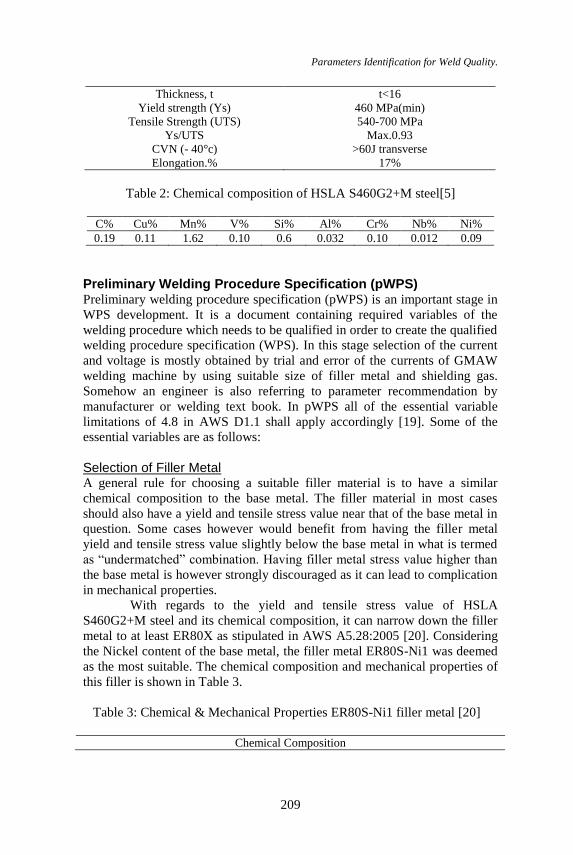
Table 2: Chemical composition of HSLA S460G2+M steel[5]
C% Cu% Mn% V% Si% Al% Cr% Nb% Ni%
0.19 0.11 1.62 0.10 0.6 0.032 0.10 0.012 0.09
Preliminary Welding Procedure Specification (pWPS) Preliminary welding procedure specification (pWPS) is an important stage in
WPS development. It is a document containing required variables of the
welding procedure which needs to be qualified in order to create the qualified
welding procedure specification (WPS). In this stage selection of the current
and voltage is mostly obtained by trial and error of the currents of GMAW
welding machine by using suitable size of filler metal and shielding gas.
Somehow an engineer is also referring to parameter recommendation by
manufacturer or welding text book. In pWPS all of the essential variable
limitations of 4.8 in AWS D1.1 shall apply accordingly [19]. Some of the
essential variables are as follows:
Selection of Filler Metal A general rule for choosing a suitable filler material is to have a similar
chemical composition to the base metal. The filler material in most cases
should also have a yield and tensile stress value near that of the base metal in
question. Some cases however would benefit from having the filler metal
yield and tensile stress value slightly below the base metal in what is termed
as “undermatched” combination. Having filler metal stress value higher than
the base metal is however strongly discouraged as it can lead to complication
in mechanical properties.
With regards to the yield and tensile stress value of HSLA
S460G2+M steel and its chemical composition, it can narrow down the filler
metal to at least ER80X as stipulated in AWS A5.28:2005 [20]. Considering
the Nickel content of the base metal, the filler metal ER80S-Ni1 was deemed
as the most suitable. The chemical composition and mechanical properties of
this filler is shown in Table 3.
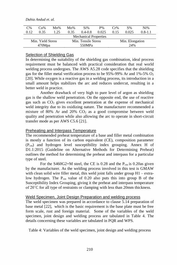
Table 3: Chemical & Mechanical Properties ER80S-Ni1 filler metal [20]
Chemical Composition
Dahia Andud et. al.
210
C% Cu% Mn% Mo% Si% P% Cr% S% Ni%
0.12 0.35 1.25 0.35 0.4-0.8 0.025 0.15 0.025 0.8-1.1
Mechanical Properties
Min. Yield Stress Min. Tensile Stress Min. Elongation
470Mpa 550MPa 24%
Selection of Shielding Gas In determining the suitability of the shielding gas combination, ideal process
requirement must be balanced with practical consideration that real world
welding process undergoes. The AWS A5.28 code specifies that the shielding
gas for the filler metal verification process to be 95%-99% Ar and 1%-5% O2
[20]. While oxygen is a reactive gas in a welding process, its introduction in a
small amount helps stabilizes the arc and reduces undercut, resulting in a
better weld in practice.
Another drawback of very high to pure level of argon as shielding
gas is the shallow weld penetration. On the opposite end, the use of reactive
gas such as CO2 gives excellent penetration at the expense of mechanical
weld integrity due to its oxidizing nature. The manufacturer recommended a
mixture of 80% Ar and 20% CO2 as a good compromise between weld
quality and penetration while also allowing the arc to operate in short-circuit
transfer mode as per AWS C5.6 [21].
Preheating and Interpass Temperature The recommended preheat temperature of a base and filler metal combination
is mostly a function of its carbon equivalent (CE), composition parameter
(Pcm) and hydrogen level susceptibility index grouping. Annex H of
D1.1:2015 (Guideline on Alternative Methods for Determining Preheat)
outlines the method for determining the preheat and interpass for a particular
type of steel.
For the S460G2+M steel, the CE is 0.28 and the Pcm is 0.20as given
by the manufacturer. As the welding process involved in this test is GMAW
with clean solid wire filler metal, this weld joint falls under group H1 – extra-
low hydrogen. The Pcm value of 0.20 also puts this into group B of the
Susceptibility Index Grouping, giving it the preheat and interpass temperature
of 20˚C for all type of restraints or clamping with less than 20mm thickness.
Weld Specimen, Joint Design Preparation and welding process The weld specimen was prepared in accordance to clause 5.14 preparation of
base metal [22], which is the basic requirement is the base plate must be free
form scale, rust and foreign material. Some of the variables of the weld
specimen, joint design and welding process are tabulated in Table 4. The
details concerning these variables are tabulated in PQR and WPS.
Table 4: Variables of the weld specimen, joint design and welding process
Parameters Identification for Weld Quality.
211
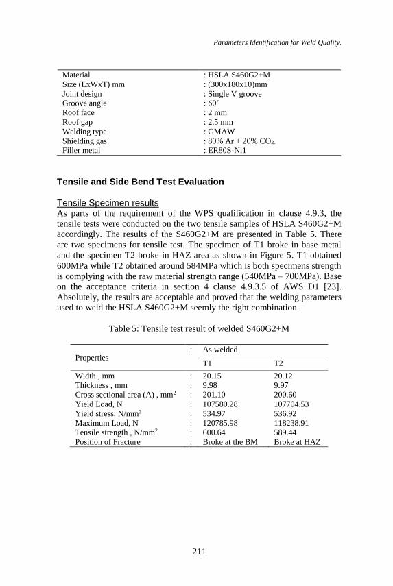
Material : HSLA S460G2+M
Size (LxWxT) mm : (300x180x10)mm
Joint design : Single V groove
Groove angle : 60˚
Roof face : 2 mm
Roof gap : 2.5 mm
Welding type : GMAW
Shielding gas : 80% Ar + 20% CO2.
Filler metal : ER80S-Ni1
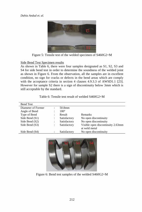
Tensile and Side Bend Test Evaluation Tensile Specimen results As parts of the requirement of the WPS qualification in clause 4.9.3, the
tensile tests were conducted on the two tensile samples of HSLA S460G2+M
accordingly. The results of the S460G2+M are presented in Table 5. There
are two specimens for tensile test. The specimen of T1 broke in base metal
and the specimen T2 broke in HAZ area as shown in Figure 5. T1 obtained
600MPa while T2 obtained around 584MPa which is both specimens strength
is complying with the raw material strength range (540MPa – 700MPa). Base
on the acceptance criteria in section 4 clause 4.9.3.5 of AWS D1 [23].
Absolutely, the results are acceptable and proved that the welding parameters
used to weld the HSLA S460G2+M seemly the right combination.
Table 5: Tensile test result of welded S460G2+M
Properties : As welded
T1 T2
Width , mm : 20.15 20.12
Thickness , mm : 9.98 9.97
Cross sectional area (A) , mm2 : 201.10 200.60
Yield Load, N : 107580.28 107704.53
Yield stress, N/mm2 : 534.97 536.92
Maximum Load, N : 120785.98 118238.91
Tensile strength , N/mm2 : 600.64 589.44
Position of Fracture : Broke at the BM Broke at HAZ
Dahia Andud et. al.
212
Figure 5: Tensile test of the welded specimen of S460G2+M
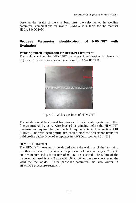
Side Bend Test Specimen results
As shown in Table 6, there were four samples designated as S1, S2, S3 and
S4 for side bend test in order to determine the soundness of the welded joint
as shown in Figure 6. From the observation, all the samples are in excellent
condition, no sign for cracks or defects in the bend areas which are comply
with the acceptance criteria in section 4 clauses 4.9.3.3 of AWSD1.1 [23].
However for sample S2 there is a sign of discontinuity below 3mm which is
still acceptable by the standard.
Table 6: Tensile test result of welded S460G2+M
Bend Test
Diameter of Former : 50.8mm
Angle of Bend : 180º
Type of Bend : Result Remarks
Side Bend (S1) : Satisfactory No open discontinuity
Side Bend (S2) : Satisfactory No open discontinuity
Side Bend (S3) : Satisfactory Visible open discontinuity 2.63mm
at weld metal
Side Bend (S4) : Satisfactory No open discontinuity
Figure 6: Bend test samples of the welded S460G2+M
Parameters Identification for Weld Quality.
213
Base on the results of the side bend tests, the selection of the welding
parameters combinations for manual GMAW is suitable for the material
HSLA S460G2+M.
Process Parameter identification of HFMI/PIT with Evaluation
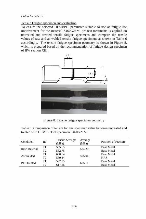
Welds Specimen Preparation for HFMI/PIT treatment
The weld specimen for HFMI/PIT parameter identification is shown in
Figure 7. This weld specimen is made from HSLA S460G2+M.
Figure 7: Welds specimen of HFMI/PIT
The welds should be cleaned from traces of oxide, scale, spatter and other
foreign material by using wire brushed or grinding before the HFMI/PIT
treatment as required by the standard requirements in IIW section XIII
[24][27]. The weld bead profile also should meet the acceptance limits for
weld profile quality level of acceptance in AWSD1.1 section 4.9.1 [23].
HFMI/PIT Treatment
The HFMI/PIT treatment is conducted along the weld toe of the butt joint.
For this treatment, the pneumatic air pressure is 6 bars, velocity is 20 to 30
cm per minute and a frequency of 90 Hz is suggested. The radius of the
hardened pin used is R = 2 mm with 30° to 60° of pin movement along the
weld toe the welds. These particular parameters are also written in
HFMI/PIT procedure treatment.
Dahia Andud et. al.
214
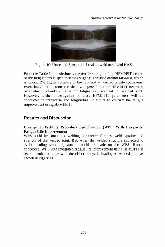
Tensile Fatigue specimen and evaluation
To ensure the selected HFMI/PIT parameter suitable to use as fatigue life
improvement for the material S460G2+M, pre-test treatments is applied on
untreated and treated tensile fatigue specimens and compare the tensile
values of raw and as welded tensile fatigue specimens as shown in Table 6
accordingly. The tensile fatigue specimen geometry is shown in Figure 8,
which is prepared based on the recommendation of fatigue design specimen
of IIW section XIII.
Figure 8: Tensile fatigue specimen geometry
Table 6: Comparison of tensile fatigue specimen value between untreated and
treated with HFMI/PIT of specimen S460G2+M
Condition ID Tensile Strength
(MPa)
Average
(MPa) Position of Fracture
Raw Material T1 585.65
584.20 Base Metal
T2 582.75 Base Metal
As Welded T1 600.64
595.04 Base Metal
T2 589.44 HAZ
PIT Treated T1 592.55
605.11 Base Metal
T2 617.66 Base Metal
Parameters Identification for Weld Quality.
215
Figure 10: Untreated Specimen –break in weld metal and HAZ
From the Table 6, it is obviously the tensile strength of the HFMI/PIT treated
of the fatigue tensile specimen was slightly increased around 605MPa, which
is around 2% higher compare to the raw and as welded tensile specimens.
Even though the increment is shallow it proved that the HFMI/PIT treatment
parameter is seemly suitable for fatigue improvement for welded joint.
However, further investigation of these HFMI/PIT parameters will be
conducted to transverse and longitudinal in future to confirm the fatigue
improvement using HFMI/PIT.
Results and Discussion
Conceptual Welding Procedure Specification (WPS) With Integrated
Fatigue Life Improvement
WPS could be contains a welding parameters for best welds quality and
strength of the welded joint. But, when the welded structure subjected to
cyclic loading some adjustment should be made on the WPS. Hence,
conceptual WPS with integrated fatigue life improvement using HFMI/PIT is
recommended to cope with the effect of cyclic loading to welded joint as
shown in Figure 11.
Dahia Andud et. al.
216
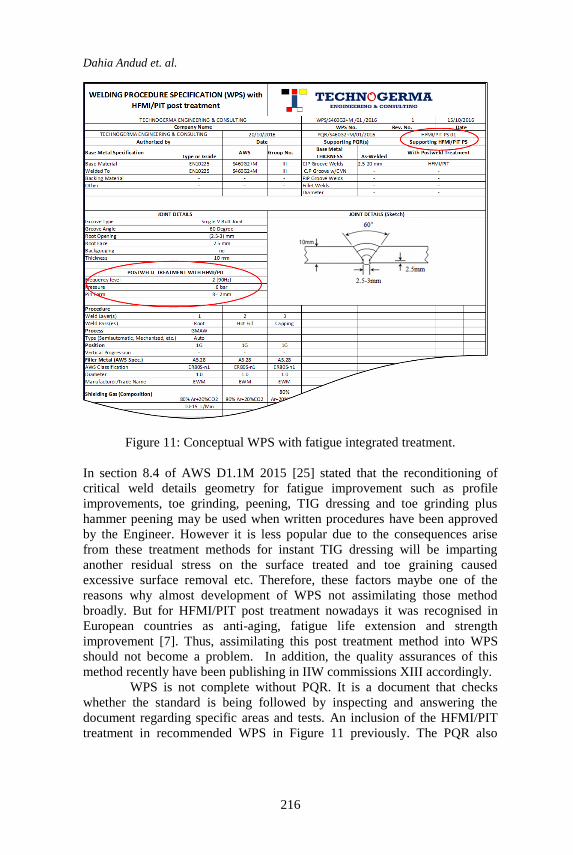
Figure 11: Conceptual WPS with fatigue integrated treatment.
In section 8.4 of AWS D1.1M 2015 [25] stated that the reconditioning of
critical weld details geometry for fatigue improvement such as profile
improvements, toe grinding, peening, TIG dressing and toe grinding plus
hammer peening may be used when written procedures have been approved
by the Engineer. However it is less popular due to the consequences arise
from these treatment methods for instant TIG dressing will be imparting
another residual stress on the surface treated and toe graining caused
excessive surface removal etc. Therefore, these factors maybe one of the
reasons why almost development of WPS not assimilating those method
broadly. But for HFMI/PIT post treatment nowadays it was recognised in
European countries as anti-aging, fatigue life extension and strength
improvement [7]. Thus, assimilating this post treatment method into WPS
should not become a problem. In addition, the quality assurances of this
method recently have been publishing in IIW commissions XIII accordingly.
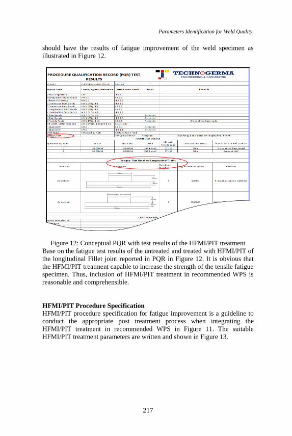
WPS is not complete without PQR. It is a document that checks
whether the standard is being followed by inspecting and answering the
document regarding specific areas and tests. An inclusion of the HFMI/PIT
treatment in recommended WPS in Figure 11 previously. The PQR also
Parameters Identification for Weld Quality.
217
should have the results of fatigue improvement of the weld specimen as
illustrated in Figure 12.
Figure 12: Conceptual PQR with test results of the HFMI/PIT treatment
Base on the fatigue test results of the untreated and treated with HFMI/PIT of
the longitudinal Fillet joint reported in PQR in Figure 12. It is obvious that
the HFMI/PIT treatment capable to increase the strength of the tensile fatigue
specimen. Thus, inclusion of HFMI/PIT treatment in recommended WPS is
reasonable and comprehensible.
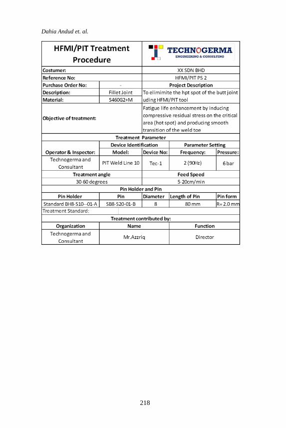
HFMI/PIT Procedure Specification HFMI/PIT procedure specification for fatigue improvement is a guideline to
conduct the appropriate post treatment process when integrating the
HFMI/PIT treatment in recommended WPS in Figure 11. The suitable
HFMI/PIT treatment parameters are written and shown in Figure 13.
Dahia Andud et. al.
218
Parameters Identification for Weld Quality.
219
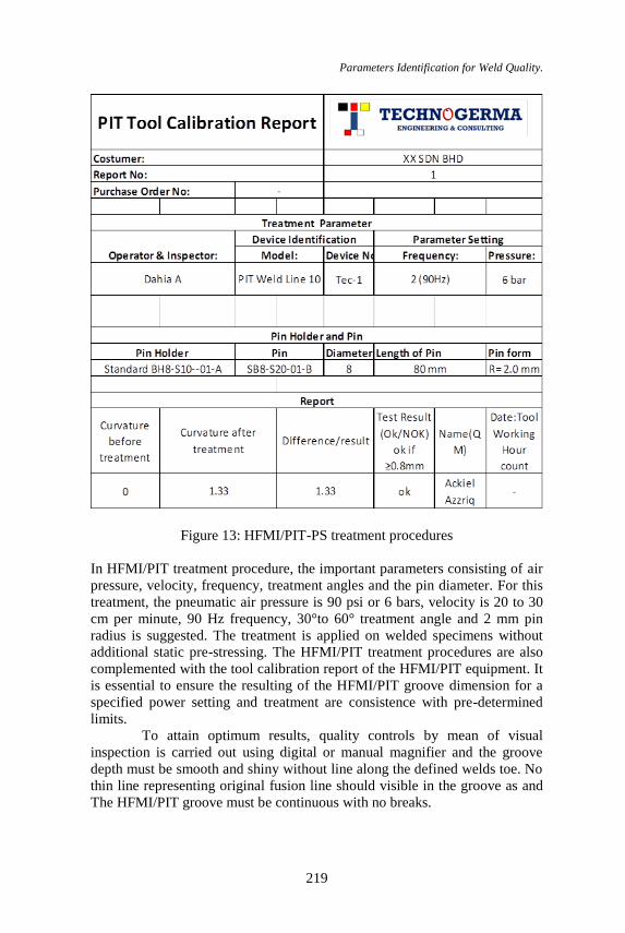
Figure 13: HFMI/PIT-PS treatment procedures
In HFMI/PIT treatment procedure, the important parameters consisting of air
pressure, velocity, frequency, treatment angles and the pin diameter. For this
treatment, the pneumatic air pressure is 90 psi or 6 bars, velocity is 20 to 30
cm per minute, 90 Hz frequency, 30°to 60° treatment angle and 2 mm pin
radius is suggested. The treatment is applied on welded specimens without
additional static pre-stressing. The HFMI/PIT treatment procedures are also
complemented with the tool calibration report of the HFMI/PIT equipment. It
is essential to ensure the resulting of the HFMI/PIT groove dimension for a
specified power setting and treatment are consistence with pre-determined
limits.
To attain optimum results, quality controls by mean of visual
inspection is carried out using digital or manual magnifier and the groove
depth must be smooth and shiny without line along the defined welds toe. No
thin line representing original fusion line should visible in the groove as and
The HFMI/PIT groove must be continuous with no breaks.
Dahia Andud et. al.
220
Conclusion In this study identification of welding parameter of manual GMAW
processes for offshore plate S460G2+M and HFMI/PIT fatigue improvement
parameters have been made in the favour of qualification of welding
procedure specification (WPS) as well as the tensile strength improvement
using HFMI/PIT. From this identification parameter processes some
conclusions arise as follows:
1. The good combination of the welding parameter for offshore
material S460G2+M can be obtained by substantial trial and error of
the current and voltage of the GMAW welding machine. 2. Integrate the HFMI/PIT treatment in WPS is essential for welded
structure exposed to dynamic loading.
3. HFMI/PIT treatment is effective for fatigue and strength
improvement of the welded joint.
4. HFMI/PIT treatment on the welded joint is reliable on the view
point of potential fatigue failure such as at the weld toe, edges etc.
5. Inclusion of HFMI/PIT treatment procedures in WPS is important in
order to be aligned with the quality assurance requirements in IIW
section XIII recommendation. Hence, it is proposed in form of
conceptual WPS with treatment procedure.
Acknowledgments
The authors would like to express their gratitude to staff members of
Welding Laboratory and Advanced Manufacturing Laboratory at Faculty of
Mechanical Engineering in UiTM Shah Alam for their support. A special
thank is also directed to PITEC GmbH in Germany and Technogerma
Engineering & Consulting for providing the equipment and encouraging the
team of Weld Fatigue Integrity with new knowledge and experience. Last but
not least, the authors would like to thank all supporting company and
university (Nusantara Technologies Sdn. Bhd. and University Kuala Lumpur
Malaysia France Institute) for providing welding specimens, test facility,
standards and advices during the fatigue test. This research is financially
sponsored by Fundamental Research Grant Scheme (FRGS) with Reference
Nr.: FRGS/1/2016/TK03/UITM/03/2.
Parameters Identification for Weld Quality.
221
References:
[1] Erdal Karadeniz, Ugur Ozsarac and Ceyhan Yildiz, The Effect of
Process Parameters on Penetration in Gas Metal Arc Welding Processes,
Material and Design, pp. 649-656 (2007).
[2] P.Sathiya, S.Aravinda, P.M. Ajith, B.Arivazhagan and A.Noorul Haq,
Microstructural Characteristics on Bead on Plate Welding of AISI 904 L
Super Austenitic Stainless Steel Using Gas Metal Arc Welding Process,
Engineering, Science and Technology, vol.2, No.6, pp. 189-199 ( 2010).
[3] I.S.Kim, J.S. Son, I.G.Kim, J.Y.Kim and O.S.Kim, A Study on
Relationship between Process Variables and Bead Penetration for
Robotic CO2 Arc Welding, Material Processing Technology, pp.139-145
(2003).
[4] Barsoum, Z., Jonsson, B.: Influence of weld quality on the fatigue
strength in seam welds. Eng.Fail. Anal. vol.18, pp. 971–979 (2010).
[5] SSAB, Plåthandboken - Att konstruera och tillverka i höghållfasta stål.
s.n., Borlänge (2010).
[6] Eleni Gogou, Use of High Strength Steel Grades for Economical Bridge
Design (2012).
[7] P. J. Haagensen, S. J Maddox, IIW Recommendations on Post Weld
Fatigue Life Improvement of Steel and Aluminium Structures,
International Institute of Welding, Paris (2010).
[8] G. Marquis and Z. Barsoum, Fatigue strength improvement of steel
structures by high-frequency mechanical impact: proposed procedures
and quality assurance guidelines, welding in the World, vol. 58, no. 1,
pp. 19–28 (Jun. 2013).
[9] Applied Ultrasonic, Esonix UIT application guide: Post weld treatment
for fatigue enhancement carbon steel welded structure.Alabama,USA,
(2006).
[10] Linde Engineering Division, Einfluss des Haemmerns auf die
Nahtschrumpfung, Germany (2010).
[11] TUV SUD Industrie Service GmbH, Einfuehrung des
Eurocodes und Lebensdauerverlaengerung von
Schweisskonstruktionen/Komponenten durch qualifizierte mechanische
Nachbehandlung, Mannheim, Germany ( 2014).
[12] M. Leitner, S. Gerstbrein, M. J. Ottersböck, and M. Stoschka, Fatigue
Strength of HFMI/PIT-treated High-strength Steel Joints under Constant
and Variable Amplitude Block Loading, Procedia Engineering, vol. 101,
pp. 251–258 (2015).
[13] Martin Leitner, Michael Stoschka, Richard Schanner Wilfried
Eichlseder; Influence of High Frequency Peening on Fatigue of High-
Strength Steels, FME Transactions, vol.40, no.3, pp.99-104 (2012).
[14] M.Laitner, Barsoum, F.Schafers, Crack propagation analysis and
rehabilitation by HFMI/PIT of pre-fatigue welded structure, welding in
the world (2016).
Dahia Andud et. al.
222
[15] Belgian Welding Institute, Summary of the results of the research
project: Improvement of welded structures fatigue life in high strength
steel grades (DURIMPROVE), Belgium (2014).
[16] J. Berg and N. Stranghoener, Fatigue Strength of Welded Ultra High
Strength Steels Improved by High Frequency Hammer Peening, Procedia
Materials Science, vol. 3, pp. 71–76 (2014).
[17] M. Leitner, M. Stoschka, and W. Eichlseder, Contribution to the
fatigue enhancement of thin-walled, high-strength steel joints by
high frequency mechanical impact treatment, IIW Document XIII, pp.
1–15 (2012).
[18] Mm Professor J Billingham, Professor J V Sharp, Dr J Spurrier and Dr P
J Kilgallon Review of the performance of high strength steels used
Offshore, ISBN 0 7176 2205, vol. 3 (2003).
[19] Section 4.8, the essential variable limitations, Welding Code Steel, An
American National Standard, AWS D1.1/D1.1M (2015).
[20] AWS A5.28: Welding Code Steel, An American National Standard,
AWS D1.1 (2005).
[21] Section C5.6, shielding gas recommendation, Welding Code Steel, An
American National Standard, Section 4, AWS D1.1/D1.1M (2015).
[22] Section 5.14, preparation of base metal, Welding Code Steel, An
American National Standard, Section 4, AWS D1.1/D1.1M (2015).
[23] Section 4 clause 4.9.3.5, the acceptance criteria, Welding Code Steel, An
American National Standard, Section 4, AWS D1.1/D1.1M (2015).
[24] P. J. Haagensen, S. J Maddox, IIW Recommendations on Post Weld
Fatigue Life Improvement of Steel and Aluminium Structures,
International Institute of Welding, Paris (2010).
[25] Section 8.4, Fatigue life enhancement, Welding Code Steel, An
American National Standard, AWS D1.1/D1.1M (2015).