Embed Size (px)
Citation preview

Journal ofMaterials Chemistry A
PAPER
Publ
ishe
d on
03
Sept
embe
r 20
13. D
ownl
oade
d by
Uni
vers
ité L
aval
on
15/0
5/20
14 2
1:34
:28.
View Article OnlineView Journal | View Issue
aDepartment of Chemical Engineering and C
University, Quebec, G1V 0A6, CanadabDepartment of Chemistry and Centre de Re
University, Quebec, G1V 0A6, Canada. E-ma
† Electronic supplementary informationexperimental procedures. See DOI: 10.103
Cite this: J. Mater. Chem. A, 2013, 1,13308
Received 26th July 2013Accepted 2nd September 2013
DOI: 10.1039/c3ta12914d
www.rsc.org/MaterialsA
13308 | J. Mater. Chem. A, 2013, 1, 1
Design of water-soluble CdS–titanate–nickelnanocomposites for photocatalytic hydrogenproduction under sunlight†
Cao-Thang Dinh,a Minh-Hao Pham,a Freddy Kleitzb and Trong-On Do*a
We report a highly active and stable nanocomposite photocatalyst for H2 generation under sunlight which
consists of a rational assembly of CdS nanoparticles, Ni clusters, and ultrathin titanate nanodisks, highly
dispersed in water.
Since the discovery of photo-induced water splitting on TiO2
electrodes,1 the use of semiconductors for photocatalytic H2
production from water has attracted tremendous interest as itallows for the production of clean and renewable energy directlyfrom solar irradiation.2 Among various photocatalysts devel-oped so far, metal suldes have been proven to be goodcandidates for photocatalytic H2 production from water con-taining sacricial reagents under visible light.3–14 In particular,CdS has been most frequently investigated, due to its efficientabsorption of visible light and sufficient conduction band (CB)potential for reduction of H+ to H2.5–14 However, CdS aloneexhibits very low photocatalytic activity due to the quickrecombination of photo-induced charge carriers. Good perfor-mances were mostly achieved in the presence of noble metal co-catalysts, such as Pt and Pd.2,5,6 Recently, nickel-basedcompounds such as cationic nickel, metallic nickel or nickelsuldes have been demonstrated to be effective cocatalysts forH2 generation.15–17 The use of earth-abundant and inexpensivenickel based cocatalysts could open up new opportunities indesign of efficient photocatalysts for H2 production.18
Among various strategies to improve the photocatalyticactivity of CdS, the most efficient method is to promote thecharge separation of photogenerated electrons and holes bycoupling CdS to other semiconductors with adequate at bandpotentials such as TiO2,7,8,19 ZnO,9,20–22 and titanate,23–25 orcoupling CdS to graphene.10,26–28 In such systems, electronsfrom the CB of CdS can transfer to other semiconductors orgraphene, leading to improved electron–hole separation. It hasbeen suggested that direct interfacial contact between semi-conductors is required to obtain good charge transfer betweenthem, and that vectorial electron transfer in multicomponent
entre de Catalyse et Chimie Verte, Laval
cherche sur les Materiaux Avances, Laval
(ESI) available: Additional gures and9/c3ta12914d
3308–13313
semiconductor composites, in which electrons are transferredbetween components in one direction, would signicantlyenhance the charge separation.11–13 However, developing such amulticomponent system requires precise control over theposition of each component in the composite. Therefore, only alimited number of studies on vectorial electron transfercomposite photocatalysts have been reported, with limitedcontrol over their structures and costly noble metals usuallyused as cocatalysts.11 Furthermore, as photocatalytic H2
production is performed in aqueous medium, high dispersionof the photocatalysts may enable this process under essentiallyhomogeneous reaction conditions, making the photocatalyticH2 production more efficient. To the best of our knowledge,such a water-soluble non-noble metal heterogeneous photo-catalyst has not been developed yet.
Herein, we report the design of a novel type of non-noblemetal nanocomposite (NC) for the photo-production of H2
under direct sunlight by enhancing both its charge separationand aqueous dispersion. The NCs which are composed of CdSnanoparticles (NPs), Ni clusters, and ultrathin titanate nano-disks (TNDs) are highly dispersed in water (namely, water-soluble CdS–TND–Ni NCs). The use of water-soluble TNDs withnegatively charged surface compensated by tetraethylammo-nium cations (TEA+–TNDs) is found to be crucial to theconstruction of highly active CdS–TND–Ni NCs. These TEA+–TNDs facilitate the design of the NCs in which CdS NPs are inintimate contact with the TNDs and Ni clusters could beselectively located on the surface of TNDs as cocatalysts. Thus,in these NCs, the generated electrons in CdS under visible lightillumination can be vectorially transferred to the Ni clustersthrough TNDs. Consequently, charge separation in the NCs isgreatly enhanced as the electrons are now separated fromholes over three different components. We found that, underdirect sunlight illumination, the NCs could generate H2 fromethanol–water solution with the rate as high as 3.182 mmol h�1
(31.820 mmol g�1 h�1), representing one of the most highlyactive metal sulphide photocatalysts in the absence of noblemetal cocatalysts.2
This journal is ª The Royal Society of Chemistry 2013

Paper Journal of Materials Chemistry A
Publ
ishe
d on
03
Sept
embe
r 20
13. D
ownl
oade
d by
Uni
vers
ité L
aval
on
15/0
5/20
14 2
1:34
:28.
View Article Online
The water-soluble CdS–TND–Ni NC photocatalysts weresynthesized by a three-step process as illustrated in Scheme S1.†First, water-soluble TNDs were synthesized. Next, CdS NPs wereintimately combined to TNDs forming water-soluble CdS–TNDhybrids. Finally, Ni clusters were selectively deposited on thesurface of TNDs in CdS–TND hybrids by photodeposition. Thepreparation of water-soluble TNDs (tetraethylammoniumcation exchange TNDs (TEA+–TND)) was performed by theapproach described in our previous work.29 Transmission elec-tronmicroscopy (TEM) (Fig. S1†) reveals that the obtained TNDsare uniform in size with a mean particle diameter of 20 nm anda thickness of 0.75 nm.
The most important step in designing CdS–TND–Ni NCs isthe synthesis of water-soluble CdS–TND hybrids. These hybridswere prepared from TNDs using a multi-cycle pathway asdepicted in Fig. 1. Each cycle consists of (i) exchanging theTEA+–TND with Cd2+ to form precipitated Cd2+–TND and (ii)reacting Cd+–TND with TEA+ cations and thiourea at 70 �C toform a TEA+–CdS–TND hybrid dispersed in water. The key pointin this strategy is that once the Cd2+ cations located between theTND layers are converted to CdS NPs attached to TNDs byreacting with S2�, the negative charge of the TND surface isagain compensated by TEA+ producing a TEA+–CdS–TND hybridwhich is soluble in water. Hence, the TEA+–CdS–TND is readyfor another cation exchange with Cd2+ starting a new cycle. As aresult, by repeating this cycle, we can both increase the contentof CdS and tune the morphology of the resulting hybrid, andconsequently, hybrid systems with desired morphology andcomposition can be obtained.
Although several methods have been used for the synthesisof CdS–TiO2 and CdS–titanate hybrids such as co-precipita-tion,30 photodeposition,31,32 chemical bath deposition,33,34 orlayer-by-layer deposition,35 our approach toward CdS–titanatehybrids is different. Here, by using water-soluble TNDs, we areable to design CdS–TND hybrid colloids stabilized by tetrae-thylammonium (TEA) cations, as conrmed by FTIR (Fig. S2†),which are highly dispersed in water under static conditions(Fig. S3†). The CdS–TND solution exhibited a negative zetapotential of �46 mV (Fig. S4†), indicating a high stability of thiscolloidal solution. It is also noted that, under similar synthesisconditions, but in the absence of TNDs, the precipitation of CdSNPs in water was observed. This water-soluble property of CdS–TND hybrids, which has not been previously reported, mayfacilitate the photocatalytic H2 production which is usuallyperformed under aqueous medium. In addition, as the CdS NPsare formed between the TND layers, the interfacial contact
Fig. 1 Illustration of the synthesis of the water-soluble CdS–TND hybrid colloids.(i) Exchanging the TEA+–TND with Cd2+ to form Cd2+–TND; (ii) reacting Cd2+–TNDwith TEA+ and thiourea at 70 �C to form TEA+–CdS–TND hybrids.
This journal is ª The Royal Society of Chemistry 2013
between CdS and TNDs is greatly enhanced which is importantfor the electron transfer between the two semiconductors.
Fig. 2a and b show TEM images at different magnicationsof the CdS–TND hybrids obtained aer 5 cycles of CdS growth. Itcan be observed from Fig. 2a that the resulting colloidal hybridsare uniform in size with a mean particle diameter of 40 nm. Thehigh-resolution TEM images (Fig. 2c and d and S5†) reveal thateach colloid consists of both TNDs and CdS NPs (see theschematic illustration of the CdS–TND hybrid structure inFig. S6†). It should be mentioned that it is difficult to observethe TNDs in the CdS–TND hybrids when they lie perpendicularto the electron beam due to their ultrathin structure. Only TNDswhich are oriented parallel to the direction of the electron beamcould be clearly visualized. Fig. 2d shows the structure of indi-vidual CdS NPs in the CdS–TND hybrid with an average crys-tallite size of 5–7 nm. The lattice fringes of the CdS NPs with ad-spacing of 0.335 nm can be assigned to the (111) lattice planeof the cubic CdS.10 Fig. 2d and S5† also show the presence ofintimate contact between CdS and TNDs. This close contactbetween the two semiconductors may enhance the chargetransfer between them, improving the charge separation andthus the photocatalytic efficiency. Elemental mapping of anindividual CdS–TND hybrid colloid particle (Fig. 2, lower panel)clearly demonstrates a homogeneous distribution of Cd, S, Ti,and O elements over the entire hybrid particle. This resultfurther conrms that TNDs and CdS nanocrystals are uniformlyintercalated together in the colloidal hybrid structure.
Fig. 2 TEM images (a and b), HRTEM images (c and d) with different magnifi-cations, and EDX elemental mapping data (lower panel) of CdS–TND hybridsobtained by 5 cycles of CdS growth. TEM images show the high dispersion anduniform size of CdS–TND hybrids. HRTEM images confirm the presence and theintimate contact of CdS NPs and TNDs in each CdS–TND hybrid colloid.
J. Mater. Chem. A, 2013, 1, 13308–13313 | 13309

Fig. 3 Comparison of the activity of different photocatalysts in the photo-catalytic production of H2 from an ethanol–water mixture under visible lightillumination.
Journal of Materials Chemistry A Paper
Publ
ishe
d on
03
Sept
embe
r 20
13. D
ownl
oade
d by
Uni
vers
ité L
aval
on
15/0
5/20
14 2
1:34
:28.
View Article Online
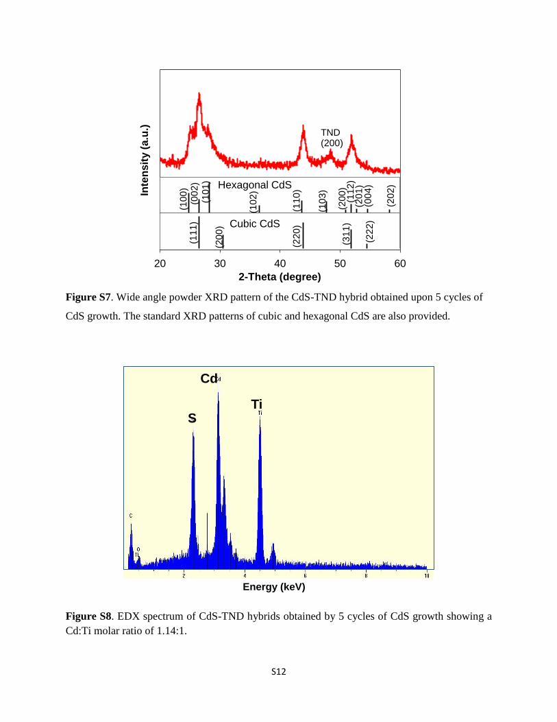
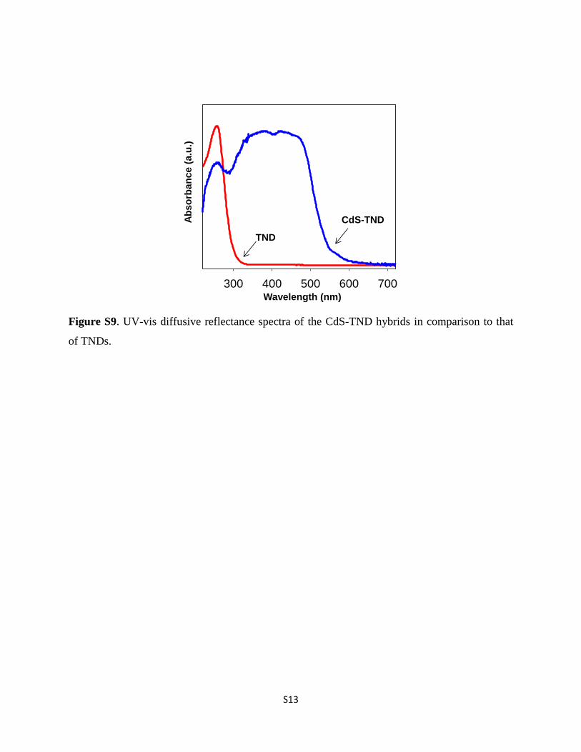
The crystallographic structure of CdS in the CdS–TNDhybrids was also revealed by powder X-ray diffraction (XRD). Asshown in Fig. S7,† all of the main diffraction peaks of the CdS inthe CdS–TND hybrids can be indexed to cubic CdS (JSPDS cardno. 10-0454). The presence of two shoulder peaks located at a2-q of 25.02� and 28.02� suggests the occurrence of hexagonalCdS in the obtained CdS–TND hybrid colloids. The compositionof the CdS–TND hybrids was determined using the EDX tech-nique as shown in Fig. S8.† The result indicates a Cd : Ti molarratio of 1.14 in the obtained hybrid sample. The amount of TEAin the CdS–TND hybrid estimated by TGA is 8.1 wt%. Fig. S9†shows the diffuse-reectance UV-vis spectra of the CdS–TNDhybrids, in comparison to the TNDs. It can be observed that theTNDs only adsorb light with wavelength lower than 320 nm. Incontrast, the CdS–TND hybrids exhibit a strong absorption inthe visible region indicating the excellent visible light harvest-ing ability of this hybrid system.
Ni clusters were selectively deposited as cocatalysts on thesurface of TNDs in the CdS–TND hybrids using photo-deposition. Typically, Ni(NO3)2 was added to the solution con-taining CdS–TND hybrids (Ni : Ti molar ratio of 1 : 20). Becausethe surface of TNDs is negatively charged, positively chargedNi2+ is selectively adsorbed on the TND surface through a cationexchange process with TEA+, resulting in CdS–TND–Ni2+. Asonly a small portion of TEA+ (�20% mol) on the TND surfacewas replaced by Ni2+, the resulted CdS–TND–Ni2+ is still highlydispersed in the solution. CdS–TND–Ni2+ was then precipitatedfrom the solution by adding an excess amount of acetone toremove any possible non-adsorbed Ni2+. The obtained precipi-tate was washed with acetone to remove the physically adsorbedNi2+ on the CdS surface to ensure that only exchanged Ni2+
cations on the surface of TNDs were retained. Note that due tothe high solubility of NiS compared to that of CdS,36 cationexchange between Ni2+ and CdS to form NiS is not favored. TheS 2p X-ray photoelectron spectroscopy (XPS) spectrum of CdS–TND–Ni2+ (Fig. S10†) also conrmed the absence of NiS in theresulting hybrid. The CdS–TND–Ni2+ was then re-dispersed inan aqueous ethanol solution 20% (v/v) and illuminated withvisible light for 2 h to reduce Ni2+ into metallic Ni clusters (seethe ESI† for details).
Elemental analysis by atomic absorption spectroscopyreveals a 1.2 wt% of Ni in the CdS–TND–Ni NCs. However,attempts to identify Ni clusters in CdS–TND–Ni NCs usingelectron microscopy resulted in ambiguous images which maybe due to the ultra-small size and high dispersion of Ni clusters.This could be due to the strong interaction between Ni2+ andTNDs and a low contrast of Ni species in CdS–TNDs. Thus, XPSwas used to monitor the change in chemical states of Ni2+ aerphoto-reduction. Fig. S11† shows the high-resolution XPSspectrum of Ni 2p of the CdS–TND–Ni NCs in comparison tothat of two reference samples, e.g., CdS–Ni and metallic Ni NPsprepared by chemical reduction using NaBH4. As seen inFig. S11,† the Ni 2p3/2 XPS spectrum of the Ni NPs referencesample shows two peaks at 852.4 and 855.3 eV, correspondingto the presence of metallic Ni and NiO, respectively.37,38 Thepresence of NiO in the reference sample could be due to thepartial oxidation of the metallic Ni NP surface upon contact
13310 | J. Mater. Chem. A, 2013, 1, 13308–13313
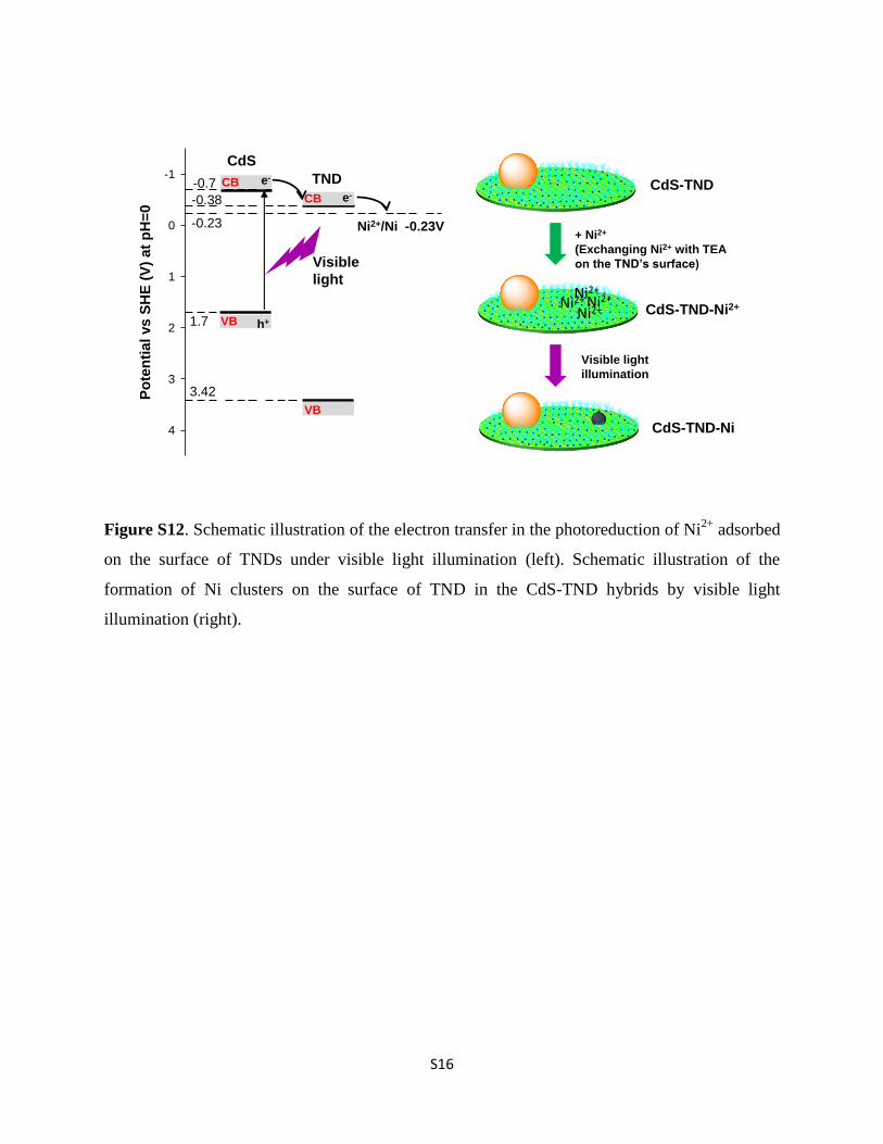
with air. A similar result was observed in the Ni 2p3/2 XPSspectrum of the CdS–Ni sample. Surprisingly, the XPS spectrumof Ni 2p3/2 of the CdS–TND–Ni NC sample exhibits only onepeak at a binding energy of 855.3 eV which is characteristic ofNiO. The absence of metallic Ni in the CdS–TND–Ni samplecould be due to the instability of metallic Ni clusters in air.These metallic Ni clusters formed by reducing Ni2+ under illu-mination are easily oxidized yielding NiO in air. The formationof metallic Ni clusters on the surface of TNDs in CdS–TNDhybrids can be described as follows: under visible light illumi-nation, the generated electrons in the CB of CdS (�0.7 V vs.SHE) can be transferred to the CB of TNDs (�0.38 V vs. SHE).39,40
Because the potential of Ni2+/Ni (�0.23 V vs. SHE, pH ¼ 0) islower than the CB level of TNDs,41,42 the electrons from the CB ofTNDs can effectively reduce Ni2+ species adsorbed on theirsurface forming metallic Ni clusters (Fig. S12†).
The photocatalytic H2 generation activity of the samples wasrst evaluated under visible light illumination for the purposeof comparison. Fig. 3 shows the photocatalytic H2-productionrates of a series of samples from an aqueous solution contain-ing 20% ethanol (v/v) under visible light illumination: CdS–TND–Ni NCs, CdS–TNDs and CdS alone (obtained under thesame synthetic conditions as those of CdS–TND hybrids, exceptthat no TNDs were added, see ESI and Fig. S13†). In addition,photocatalytic activities of CdS–Ni (1.2 wt% of Ni), CdS–Pt(1.2 wt% of Pt) and amixture of CdS NPs and TND–Ni2+ in whichNi2+ is adsorbed on the TND surface, were also evaluated. Asseen in Fig. 3, CdS alone shows very low H2 generation rates(0.098 mmol h�1 g�1) which is mainly caused by rapid recom-bination of photogenerated electrons and holes and the lack ofH2 evolution sites.5,6 Coupling CdS to TNDs improves the H2
production rate of CdS. As shown in Fig. 3, CdS–TND hybridsexhibit a H2 production rate of 0.142 mmol g�1 h�1 which isabout 1.4 times higher than that of CdS alone. It should benoted that the content of CdS in CdS–TND hybrids is 67 wt%.Thus, if the rate calculation is based on the amount of CdS, theH2 production over CdS–TND hybrids would be higher. Inter-estingly, the introduction of a Ni cocatalyst resulted in a
This journal is ª The Royal Society of Chemistry 2013

Fig. 4 Schematic illustration of the charge transfer in CdS–TND–Ni NCs in thephotocatalytic H2 production from a water–ethanol mixture under visible light. Tosimplify, only one particle of each component is shown, although a NC colloid iscomposed of several CdS NPs, TNDs and Ni clusters.
Fig. 5 H2 production from CdS–TND–Ni and CdS–Ni photocatalysts monitoredover 15 h. Every 3 h, the reaction system is bubbled with N2 for 15 min to removethe H2 inside (left). H2 production rate from ethanol–water solution with CdS–TND–Ni NCs under natural sunlight (May 7, 2013; at Laval University, QC, Canada)(right).
Paper Journal of Materials Chemistry A
Publ
ishe
d on
03
Sept
embe
r 20
13. D
ownl
oade
d by
Uni
vers
ité L
aval
on
15/0
5/20
14 2
1:34
:28.
View Article Online
signicant improvement in the photocatalytic H2 productionactivity for both CdS and CdS–TND hybrids. The H2 productionrate of CdS–Ni (1.892 mmol g�1 h�1) is even higher than that ofa reference CdS–Pt (0.983 mmol g�1 h�1) using noble metal Ptas the cocatalyst (Fig. 3). This conrms that Ni can act as anexcellent cocatalyst for the photocatalytic H2 generation fromethanol–water solution. As shown in Fig. 3, with Ni as thecocatalyst, CdS–Ni exhibits a 19-fold higher photocatalyticactivity compared to that of CdS alone. More impressively, inthe presence of Ni clusters on the TND surface, CdS–TND–NiNCs show a signicantly increased photocatalytic activity, by afactor of 77, as compared to CdS–TND hybrids. The apparentquantum yield was measured to be 21% at 420 nm, which isamong the highest values reported for noble metal-free CdS-based photocatalysts studied under similar conditions.2 Notethat a simple mixture of CdS NPs and TND–Ni2+ with a similarcomposition to that of CdS–TND–Ni NCs exhibited a very low H2
production rate. Thus, these results reveal a cooperative effectof TNDs and Ni for the enhancement of H2 production usingCdS. In particular, intimate contact and proper organization ofthe three components in the NCs are required to achieve highphotocatalytic performance.
Although there are numerous reports about CdS-basedphotocatalysts with different nanostructures and high H2
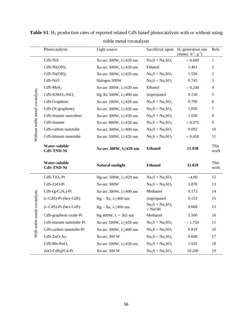
production rate under visible light irradiation using differentsacricial agents such as lactic acid, methanol, ethanol, prop-anol and Na2S + Na2SO3, most of them are achieved with a Ptcocatalyst.2 For example, Amirav et al.43 reported a nano-heterostructure composed of a Pt-tipped CdS rod with anembedded CdSe seed which exhibited a H2 generation rate of 40mmol g�1 h�1 under visible light illumination, and an apparentquantum yield of 20% at 420 nm using methanol as the sacri-cial agent. Li et al.10 reported the H2 gas evolved at a rate of 56mmol g�1 h�1 corresponding to an apparent quantum yield of22.5% at 420 nm for the samples of Pt-loaded CdS–cluster-decorated graphene nanosheets using lactic acid as the sacri-cial agent. Recently, Wang et al.22 reported a H2 generation rateof 19.2 mmol g�1 h�1 under visible light illumination for thesample of the Pt-loaded ZnO–CdS@Cd heterostructure usingNa2S + Na2SO3 as the sacricial agent. Without noble–metalcocatalysts, however, most of the reported CdS-based photo-catalysts exhibit H2 generation rates of 0.070–1.600mmol g�1 h�1
(Table S1†) using either ethanol or Na2S + Na2SO3 as the sacri-cial agent, which are several times lower than the observed H2
generation rate of the present CdS–TND–Ni NC photocatalyst(11.038 mmol g�1 h�1). The high H2 production activity of CdS–TND–Ni NCs under visible light can be due to Ni clusters highlydispersed on the surface of TNDs. Under visible light irradia-tion, the generated electrons from the CB of CdS can effectivelybe injected into the CB of TNDs due to an intimate interactionbetween the two semiconductors (see the scheme in Fig. 4). Niclusters deposited on the surface of TNDs can cap the electronsfrom TNDs and act as active sites for H2 evolution. Thus, theelectrons and holes in the NCs are separated from each otherover three different components, leading to effective prolonga-tion of the charge carrier lifetime and enlargement of thereaction space, and consequently, the improvement of the
This journal is ª The Royal Society of Chemistry 2013
photocatalytic H2 production. In addition, the presence of TEAon the surface of TNDs makes the NCs highly dispersed in theethanol–water mixture, but does not affect the surface of CdSNPs and Ni clusters. Thus, the reactants (water and ethanol) arefree to access the active sites on the CdS and Ni surface withhigh diffusion rate. Therefore, the photocatalytic rate is signif-icantly enhanced.
The stability of the CdS–Ni and CdS–TND–Ni was studied byperforming recycle experiments under the same conditions.Aer 5 cycles, the photocatalytic H2 production rate of CdS–Niphotocatalysts decreased gradually and remained only 52% ofthe initial rate (Fig. 5). In contrast, the CdS–TND–Ni NCsshowed no photocatalytic activity loss, indicating the highstability of this photocatalyst for the H2 generation. It isimportant to note that metal sulde photocatalysts are usuallyunstable during photocatalytic reaction due to (i) reduction ofmetal cations in metal suldes by generated electrons; (ii)oxidation of S2� by generated holes; and (iii) detachment ofmetallic NP cocatalysts from themetal sulde surface due to thephotooxidation of metal particles.5,6,43–45 In the case of CdS–TND–Ni NCs, adequate electron transfer from the CB of CdS tothat of TNDs originated from the intimate interactions betweenCdS and TNDs is benecial for preventing the reduction of Cd2+.In addition, the high dispersion of the photocatalysts in thereacting medium favors the accessibility of the sacricial agent(ethanol) to the surface of CdS, leading to the suppression of theoxidation of S2� on CdS. Furthermore, in the CdS–TND–Ni NCs,
J. Mater. Chem. A, 2013, 1, 13308–13313 | 13311

Journal of Materials Chemistry A Paper
Publ
ishe
d on
03
Sept
embe
r 20
13. D
ownl
oade
d by
Uni
vers
ité L
aval
on
15/0
5/20
14 2
1:34
:28.
View Article Online
only CdS can generate holes in the valence band (VB) undervisible light illumination. These holes in the VB of CdS (+1.7 Vvs. SHE) cannot be transferred to the VB of TNDs (+3.4 V vs.SHE).39,40 Thus, Ni clusters are unlikely to be directly oxidized byholes on CdS NPs as they are only located on the surface ofTNDs. This is different from the oxidation of nickel species onthe surface of semiconductors when they are directly contactedwith photogenerated holes.46 Taking into account these uniquefeatures, it is not surprising that the CdS–TND–Ni NCs exhibitnot only high activity, but also high stability in the photo-catalytic generation of H2. We observed that the CdS–TND–Niphotocatalyst was still highly dispersed in the solution evenaer 5 cycles of photocatalytic reaction. The TGA analysis of thesamples before and aer 5 cycles of reaction (Fig. S14†) showedidentical curves, indicating that the TEA cations on the surfaceof TNDs are not decomposed during the photocatalytic process.In addition, TEM images (Fig. S15†) indicate that themorphologyof the CdS–TND–Ni NCs is preserved aer the 5 cycles.
Natural sunlight was used to evaluate the potential applica-tion of the CdS–TND–Ni NCs in H2 production. As shown inFig. 5 (right), H2 was readily produced from aqueous ethanolsolution containing NC photocatalysts under natural sunlightbetween 11:00 am and 4:00 pm on May 7, 2013 (Quebec city,QC). Impressively, the NCs could generate H2 with the averagerate as high as 1.232 mmol h�1 (12.326 mmol g�1 h�1) over anirradiation area of 125 cm2, which is even higher than thatmeasured under visible light in the laboratory. Moreover, due tothe high dispersion of CdS–TND–Ni NCs in ethanol–watersolution, the H2 generation rate can be further increased simplyby increasing the irradiation area. For example, with the sameamount of photocatalyst (100 mg) and ethanol–water solution(500 ml), when the irradiation area was 4 times increased, a H2
generation rate up to 3.182 mmol h�1 (31.820 mmol g�1 h�1)was obtained under direct sunlight illumination. These resultscombined with the high stability of CdS–TND–Ni NCs prove thegreat potential of practical application of the water-soluble CdS–TND–Ni NCs for H2 production under sunlight. In this case,ethanol was used as the sacricial agent; however, otherrenewable biomass derivatives such as glycerol can also be usedas sacricial agents to make this strategy feasible.
In summary, we have designed a novel type of NC photo-catalyst for the production of H2 under sunlight irradiation,consisting of CdS NPs, TNDs, and Ni clusters by using water-soluble TNDs with negatively charged surface compensated byTEA+ cations. This design has enhanced signicantly the elec-tron–hole separation in NC photocatalysts by combining CdS,TNDs, and Ni in such a way that a vectorial electron transferfrom CdS to TNDs and then to Ni is enabled. Moreover, the NCsare highly dispersed in water medium. Thus, the obtained NCsshow high stability and the highest photocatalytic activityamong all of the non-noble metal sulphide-based catalysts forthe H2 generation under visible light, and can thus provideviable solutions for the development of practical photocatalystsfor H2 production under sunlight. We also believe that ourdesign can be extended to other metal sulde-based NCs, andthus could be applied to produce high performance NCs forapplications beyond photocatalysis.
13312 | J. Mater. Chem. A, 2013, 1, 13308–13313
Acknowledgements
This work was supported by the NSERC (Canada) and FQRNT(Province of Quebec). The authors thank Yongbeom Seo andProf. Ryong Ryoo (KAIST, Korea) for the access to high-resolu-tion TEM microscopy data.
Notes and references
1 A. Fujishima and K. Honda, Nature, 1972, 238, 37.2 X. B. Chen, S. H. Shen, L. J. Guo and S. S. Mao, Chem. Rev.,2010, 110, 6503.
3 I. Tsuji, H. Kato, H. Kobayashi and A. Kudo, J. Am. Chem.Soc., 2004, 126, 13406.
4 J. Zhang, J. Yu, Y. Zhang, Q. Li and J. R. Gong, Nano Lett.,2011, 11, 4774.
5 N. Bao, L. Shen, T. Takata and K. Domen, Chem. Mater., 2008,20, 110.
6 G. Ma, H. Yan, J. Shi, X. Zong, Z. Lei and C. Li, J. Catal., 2008,260, 134.
7 S. C. Hayden, N. K. Allam and M. A. El-Sayed, J. Am. Chem.Soc., 2010, 132, 14406.
8 J. Ryu, S. H. Lee, D. H. Nam and C. B. Park, Adv. Mater., 2011,23, 1883.
9 X. Wang, G. Liu, Z. Chen, F. Li, L. Wang, G. Lu and H. Cheng,Chem. Commun., 2009, 3452.
10 Q. Li, B. Guo, J. Yu, J. Ran, B. Zhang, H. Yan and J. R. Gong, J.Am. Chem. Soc., 2011, 133, 10878.
11 H. Park, W. Choi and M. R. Hoffmann, J. Mater. Chem., 2008,18, 2379.
12 I. V. Lightcap, T. H. Kosel and P. V. Kamat, Nano Lett., 2010,10, 577.
13 A. Mukherji, B. Seger, G. Q. Lu and L. Wang, ACS Nano, 2011,5, 3483.
14 P. D. Tran, L. H. Wong, J. Barber and J. S. C. Loo, EnergyEnviron. Sci., 2012, 5, 5902.
15 Z. Han, F. Qiu, R. Eisenberg, P. L. Holland and T. D. Krauss,Science, 2012, 338, 1321.
16 W. Wang, S. Liu, L. Nie, B. Cheng and J. Yu, Phys. Chem.Chem. Phys., 2013, 15, 12033.
17 Y. P. Yuan, S. W. Cao, L. S. Yin, L. Xu and C. Xue, Int. J.Hydrogen Energy, 2013, 38, 7218.
18 G. Wang and Y. Li, ChemCatChem, 2013, 5, 1294.19 H. Wang, G. Wang, Y. Ling, M. Lepert, C. Wang, J. Z. Zhang
and Y. Li, Nanoscale, 2012, 4, 1463.20 T. Peng, K. Dai, H. Yi, D. Ke, P. Cai and L. Zan, Chem. Phys.
Lett., 2008, 460, 216.21 X. Wang, G. Liu, G. Lu and H. Cheng, Int. J. Hydrogen Energy,
2010, 35, 8199.22 X. Wang, G. Liu, L. Wang, Z. G. Chen, G. Q. M. Lu and
H. M. Cheng, Adv. Energy Mater., 2012, 2, 42.23 H. N. Kim, T. W. Kim, I. Y. Kim and S. J. Hwang, Adv. Funct.
Mater., 2011, 21, 3111.24 Y. Zhang, Y. Tang, X. Liu, Z. Dong, H. H. Hng, Z. Chen,
T. C. Sum and X. Chen, Small, 2013, 9, 996.25 Y. Chen, L. Wang, G. M. Lu, X. Yao and L. Guo, J. Mater.
Chem., 2011, 21, 5134.
This journal is ª The Royal Society of Chemistry 2013

Paper Journal of Materials Chemistry A
Publ
ishe
d on
03
Sept
embe
r 20
13. D
ownl
oade
d by
Uni
vers
ité L
aval
on
15/0
5/20
14 2
1:34
:28.
View Article Online
26 A. Ye, W. Fan, Q. Zhang, W. Deng and Y. Wang, Catal. Sci.Technol., 2012, 2, 969.
27 L. Jia, D. H. Wang, Y. X. Huang, A. W. Xu and H. Q. Yu, J.Phys. Chem. C, 2011, 115, 11466.
28 P. Gao, J. Liu, S. Lee, T. Zhang and D. D. Sun, J. Mater. Chem.,2012, 22, 2292.
29 C. T. Dinh, Y. Seo, T. D. Nguyen, F. Kleitz and T. O. Do,Angew. Chem., Int. Ed., 2012, 51, 6608.
30 Y. Bessekhouad, D. Robert and J. V. Weber, J. Photochem.Photobiol., A, 2004, 163, 569.
31 H. Tada, M. Fujishima and H. Kobayashi, Chem. Soc. Rev.,2011, 40, 4232.
32 M. Fujii, K. Nagasuna, M. Fujishima, T. Akita and H. Tada, J.Phys. Chem. C, 2009, 113, 16711.
33 Q. Shen, J. Kobayashi, L. J. Diguna and T. Toyoda, J. Appl.Phys., 2008, 103, 84304.
34 S. Gorer and G. Hodes, J. Phys. Chem., 1994, 98, 5338.35 D. R. Baker and P. V. Kamat, Adv. Funct. Mater., 2009, 19, 805.36 J. R. Goates, M. B. Gordon and N. D. Faux, J. Am. Chem. Soc.,
1952, 74, 835.
This journal is ª The Royal Society of Chemistry 2013
37 Handbook of X-ray Photoelectron Spectroscopy, ed. J. F.Moulder, W. F. Stickle, P. E. Sobol, K. D. Bomben and J.Chastain, Physical Electronics, Inc., Eden Prairie, MN, 1992.
38 M. C. Biesinger, B. P. Payne, L. W. M. Lau, A. Gerson andR. S. C. Smart, Surf. Interface Anal., 2009, 41, 324.
39 J. Ran, J. Yu and M. Jaroniec, Green Chem., 2011, 13, 2708.40 N. Sakai, Y. Ebina, K. Takada and T. Sasaki, J. Am. Chem. Soc.,
2004, 126, 5851.41 J. G. Yu, Y. Hai and B. Cheng, J. Phys. Chem. C, 2011, 115,
4953.42 Standard Potentials in Aqueous Solution, ed. A. J. Bard, R.
Parsons and J. Jordan, Marcel Dekker, New York, 1985.43 L. Amirav and A. P. Alivisatos, J. Phys. Chem. Lett., 2010, 1,
1051.44 K. Domen, J. N. Kondo, M. Hara and T. Takata, Bull. Chem.
Soc. Jpn., 2000, 73, 1307.45 J. Zhang, J. Yu, M. Jaroniec and J. R. Gong, Nano Lett., 2012,
12, 4584.46 G. Wang, Y. Ling, X. Lu, T. Zhai, F. Qian, Y. Tong and Y. Li,
Nanoscale, 2013, 5, 4129.
J. Mater. Chem. A, 2013, 1, 13308–13313 | 13313

S1
Supporting Information
Design of Water-soluble CdS-Titanate-Nickel Nanocomposites for
Photocatalytic Hydrogen Production under sunlight
Cao-Thang Dinh,† Minh-Hao Pham,
† Freddy Kleitz,
§ and Trong-On Do*
†
† Department of Chemical Engineering and Centre de Catalyse et Chimie Verte (C3V), Laval
University, Quebec, G1V 0A6, Canada
§ Department of Chemistry and Centre de Recherche sur les Matériaux Avancés (CERMA),
Laval University, Quebec, G1V 0A6, Canada
Corresponding Author : [email protected]
Chemicals. All chemicals were used as received; Titanium butoxide (TB), benzyl alcohol (BA),
oleylamine (OM), benzyl ether, tetraethylammonium (TEA) hydroxide, nickel nitrate, cadmium
nitrate, thiourea, chloroplatinic acid, were purchased form Aldrich. Absolute ethanol, acetone,
and toluene solvents were of analytical grade and were also purchased form Aldrich.
Synthesis of titanate nanodisks. In a typical synthesis, 2g of TB, 12 g of OM, 12g of BA
(OM:BA weight ratio of 1:1), and 30g of benzyl ether were added to a 100-mL round-bottom
flask. The reaction mixture was heated to 190 oC at the heating rate 5
oC/min under nitrogen
flow. After 20 h, the reaction was stopped and cooled down to room temperature. After addition
of excess absolute ethanol, the TNDs were obtained by centrifugation. The obtained nanodisks
were then re-dispersed in toluene and re-precipitated with ethanol. This process was repeated
three times to remove the un-reacted reagents.
Tetraethylammonium-exchanged titanate nanodisks. The as-synthesized TNDs were treated
with tetraethylammonium hydroxide to obtain water-soluble TEA-TNDs. Typically, 5 mmol of
as-synthesized TNDs (according to Ti atom) were dispersed in a mixture of TEAOH (15 mmol),
ethanol (15 ml) and water (15 ml). The mixture was stirred overnight at room temperature. An
excess of acetone was added to the obtained clear solution to precipitate TNDs. The precipitate
was then washed several times with acetone and finally re-dispersed in 10 ml of water.

S2
Synthesis of CdS-TND hybrids. The CdS-TND hybrids were synthesized using a multi-cycle
pathway (Figure 1). In the first cycle, Cd2+
cations-exchanged TNDs were prepared.
Accordingly, the TEA-TNDs dispersed in water were gradually added to a solution containing
Cd2+
cations (Cd:Ti atomic ratio of 1:2) under stirring. The resulting Cd2+
-TND precipitate was
then washed several times with water to remove un-exchanged Cd2+
cations. To obtain the CdS-
TND hybrid, Cd2+
-TNDs was then dispersed in water. To this mixture was added a solution
containing both TEAOH and thiourea (TEAOH : thiourea : Cd2+
molar ratio of 1:1:0.3). Next,
the obtained mixture was heated to 70oC. At this temperature, S
2- ions are released by the
alkaline hydrolysis of thiourea and reacted with Cd2+
yielding CdS nanocrystals. After 1 hour of
heating, a yellow transparent solution was formed indicative of the formation of the CdS-TND
hybrids. To this clear solution acetone was added in excess to precipitate CdS-TNDs. The yellow
precipitate was then washed several times with acetone and finally re-dispersed in water for a
subsequent CdS growth cycle. To start the second CdS growth cycle, the CdS-TND hybrids
obtained in the previous cycle was used as precursor instead of TEA-TNDs. The following steps
were similar to those of the previous cycle. This CdS growth cycle was repeated 5 times to
obtain the final TND-CdS hybrid colloids. The obtained CdS-TND hybrids were dispersed in
water with the concentration of 10 mg/cm3.
Synthesis of CdS-TND-Ni nanocomposites. To the CdS-TND hybrid solution was added a
solution of Ni(NO3)2 (Ni2+
:Ti molar ratio of 1:20). The mixture was then stirred for 1 hour.
During this process, Ni2+
was adsorbed on the surface of TNDs through cation exchange process
with TEA+, resulting in CdS-TND-Ni
2+. The obtained CdS-TND-Ni
2 was then precipitated from
the solution by adding an excess amount of acetone to remove any possible non-exchanged Ni2+
.
The obtained precipitate was washed with acetone to remove the physically adsorbed Ni2+
on the
CdS surface to ensure that Ni2+
only appeared on the surface of TNDs before being reduced. The
CdS-TND-Ni2+
was then re-dispersed in an aqueous ethanol solution 20% (v/v) in a gas-tight
reaction cell. The solution was evacuated and purged with nitrogen for 10 minutes to completely
remove the dissolved oxygen. Finally, the solution was illuminated for 2 hours by a 300W Xe arc
lamp equipped with an UV-cutoff filter (≥420 nm). The obtained CdS-TND-Ni NC solution was
kept under nitrogen for photocatalytic hydrogen generation test.

S3
Synthesis of CdS nanoparticles. Pure CdS nanoparticles were prepared in the similar conditions
to those of the CdS-TND hybrids, but in the absence of TNDs. A mixture of TEAOH and
thiourea was added to the solution containing Cd2+
cations. The mixture was then heated to 70°C
for 1 hour. The resulting precipitate was then washed several times with water and dried at 70°C
for 5 hours.
Characterization. Transmission electron microscopy (TEM) images of the samples were
obtained on a JOEL JEM 1230 operated at 120kV. High resolution TEM (HRTEM) images were
performed on Philips G2 F30 Tecnai instrument operated at 300kV. Powder X-ray diffraction
(XRD) patterns of the samples were obtained on a Bruker SMART APEXII X-ray diffractometer
equipped with a Cu K radiation source (=1.5418 Å). Thermal analyses of the samples were
carried out at a heating rate of 10 °C/min under a nitrogen flow up to 700 °C using a Perkin-
Elmer TGA thermogravimetric analyzer. Zeta potential measurements were performed with a
Zetasizer Nano ZS in water at 25 oC. X-ray photoelectron spectroscopy (XPS) measurements
carried out in an ion-pumped chamber (evacuated to 10-9 Torr) of a photoelectron spectrometer
(Kratos Axis-Ultra) equipped with a focused X-ray source (Al K, hv = 1486.6 eV). The UV-vis
spectra were recorded on a Cary 300 Bio UV-visible spectrophotometer. Fourier transform
infrared (FTIR) absorption spectra were measured with a FTS 45 infrared spectrophotometer
with the KBr pellet technique.
Photocatalytic testing.
Photocatalytic reactions for hydrogen production under natural sunlight were carried out in an
air-tight Pyrex tube reactor (irradiation area of 125 cm2). Photocatalyst samples (0.1 g) were
dispersed in 500 mL of an ethanol-water mixture (20 v/v %) in the reactor. The solution was
purged with N2 gas for 30 min before reaction in order to eliminate dissolved oxygen. The
volume of gas produced was measured by recording the displacement of water level in an
inverted and graduated water-filled burette. The hydrogen gas produced was also confirmed by
gas chromatography equipped with TCD detector and carboxen-1010 capillary column.
The photocatalytic hydrogen generation experiments were also performed under visible light
irradiation for the purpose of comparison between the samples. The photocatalytic reactions
were carried out in a gas-tight 200 ml Pyrex reaction cell at ambient temperature and
atmospheric pressure under visible light illumination. In a typical photocatalytic experiment, 20

S4
mg of photocatalysts were dispersed in 70 ml of aqueous solution containing 20 % (v/v) of
ethanol. In the case of CdS-Ni and CdS-Pt photocatalyts, Ni(NO3)2 and H2PtCl6 (1.2 wt% of
metallic cocatalysts) were also added, respectively. The mixture was evacuated and purged with
nitrogen for 30 minutes to remove dissolved oxygen. Then, it was illuminated with a 300W Xe
arc lamp equipped with an UV-cutoff filter (≥420 nm) under stirring condition. A 0.5 mL of gas
was sampled intermittently through the septum, and hydrogen was analyzed by gas
chromatography equipped with TCD detector and carboxen-1010 capillary column.
The apparent quantum yield (QY) was measured under the same photocatalytic reaction
conditions. The photon flux was measured with Newport's power meter equipped with a
thermopile optical detector.
. The QY was calculated according to following equation:
( )

S5
Scheme S1. Schematic illustration of the three steps in the preparation of water-soluble CdS-
TND-Ni NCs: (i) synthesis of water-soluble TNDs; (ii) assembly of CdS-TND hybrids; and (iii)
formation of water-soluble CdS-TND-Ni NCs.
Water - soluble
TNDsWater - soluble
CdS-TND
Water - soluble
CdS-TND-Ni
S6
Table S1. H2 production rates of reported related CdS based photocatalysts with or without using
noble metal cocatalysts
Photocatalysts Light source Sacrificial agent H2 generation rate
(mmol. h-1
. g-1
)
Refs
Wit
ho
ut
no
ble
met
al c
oca
taly
sts
CdS-NiS Xe-arc 300W, ≥420 nm Na2S + Na2SO3 0.600 1
CdS-Ni(OH)2 Xe-arc 300W, ≥420 nm Ethanol 1.461 2
CdS-Ni(OH)2 Xe-arc 300W, ≥420 nm Na2S + Na2SO3 1.556 2
CdS-NiO Halogen 500W Na2S + Na2SO3 0.745 3
CdS-MoS2 Xe-arc 300W, ≥420 nm Ethanol 0.240 4
CdS-KNbO3-NiOx Hg-Xe 500W, ≥400 nm isopropanol 0.150 5
CdS-Graphene Xe-arc 200W, ≥420 nm Na2S + Na2SO3 0.700 6
CdS-(N-graphene) Xe-arc 300W, ≥420 nm Na2S + Na2SO3 1.050 7
CdS-titanate nanosheet Xe-arc 300W, ≥420 nm Na2S + Na2SO3 1.020 8
CdS-titanate Xe-arc 800W, ≥420 nm Na2S + Na2SO3 0.075 9
CdS-carbon nanotube Xe-arc 300W, ≥400 nm Na2S + Na2SO3 0.092 10
CdS-titanate nanotube Xe-arc 500W, ≥420 nm Na2S + Na2SO3 0.450 11
Water-soluble
CdS-TND-Ni Xe-arc 300W, ≥420 nm Ethanol 11.038
This
work
Water-soluble
CdS-TND-Ni Natural sunlight Ethanol 31.820
This
work
Wit
h n
ob
le m
etal
co
cata
lyst
s
CdS-TiO2-Pt Hg-arc 500W, ≥420 nm Na2S + Na2SO3 4.00 12
CdS-ZnO-Pt Xe-arc 300W Na2S + Na2SO3 3.870 13
CdS-(g-C3N4)-Pt Xe-arc 300W, ≥400 nm Methanol 0.173 14
(c-CdS)-Pt-(hex-CdS) Hg – Xe, ≥400 nm isopropanol 0.153 15
(c-CdS)-Pt-(hex-CdS) Hg – Xe, ≥400 nm Na2S + Na2SO3
+ NaOH 0.668 15
CdS-graphene oxide-Pt Hg 400W, = 365 nm Methanol 5.500 16
CdS-titanate nanotube-Pt Xe-arc 500W, ≥420 nm Na2S + Na2SO3 1.750 11
CdS-carbon nanotube-Pt Xe-arc 300W, ≥400 nm Na2S + Na2SO3 0.819 10
CdS-ZnO-Au Xe-arc 300 W Na2S + Na2SO3 0.608 17
CdS:Mn-RuOx Xe-arc 500W, ≥420 nm Na2S + Na2SO3 1.935 18
ZnO-CdS@Cd-Pt Xe-arc 300 W Na2S + Na2SO3 19.200 19

S7
Figure S1. TEM images of the as-synthesized TNDs dispersed in toluene (a), and precipitated in
ethanol (b), and HRTEM of TNDs aligned perpendicular to the electron beam (c). Due to the
ultrathin structure of TNDs, in the highly dispersed state (i.e. dispersed in toluene), these TNDs
tend to lay parallel to the surface of the TEM’s grid. Thus, a mean TND’s diameter of around 20
nm can be observed (figure a). In the precipitated state (i.e. precipitated in ethanol), some
aggregate of TNDs could lay parallel to the direction of the electron beam (figure b), we
therefore can calculate the thickness of the TNDs (0.75 nm). Figure c shows a d-spacing of 0.19
nm which is corresponding to the crystalline lattice of (200) plane in the lepidocrocide-type
titanate structure.
c
20 nm
b
a
2 nm
100 nm
20 nm
0.19 nm
TND (200)0.75 nm

S8
Figure S2. FTIR spectra of as-synthesized OM-TND, TEA-TND obtained by treated OM-TND
with TEA, and CdS-TND hybrids. FTIR spectra of all samples show two peaks at 2920 and 2850
cm-1
corresponding to the asymmetric and symmetric stretching mode of methylene groups
present in the alkyl chain of OM and TEA, respectively. In addition, no absorption at 3004 cm-1
which would correspond to the stretching vibration of the C-H bond in the C=C group of OM
molecules presents on the FTIR spectrum TEA-TND, indicating that the OM molecules adsorbed
on the surface of TNDs have been fully displaced by the TEA cations.
Tra
nsm
itta
nce (
a.u
.)
29202850
3004 OM-TND
TEA-TND
Csp2-H
Csp3-H
Csp3-H
Wavenumber (cm-1
)
260027002800290030003100
CdS-TND

S9
Figure S3. Photo of CdS-TND hybrid colloidal solution showing a clear transparency (left).
Photo of CdS-TND solution with a typical Tyndall Effect of colloidal solution.
Figure S4. Zeta potential of CdS-TND hybrid colloidal solution measured at pH = 7.5. The CdS-
TND solution exhibited a negative zeta potential of 46 mV, indicating a high stability of this
colloidal solution. ASTM defines colloids with zeta potentials higher than 40 mV (negative or
positive) to have “good stability.” 20

S10
Figure S5. Large area HRTEM image of CdS-TND hybrid obtained by 5 cycles of CdS growth
showing the intimate contact between CdS nanoparticles and TNDs
10 nm

S11
Figure S6. Schematic illustration of the structure of CdS-TND hybrid colloid. Each colloid
consists of several TNDs and CdS nanoparticles. The TNDs and CdS nanoparticles are mutually
intercalated forming hybrid colloids with multipoint contacts at the interface between the two
nano-domains.
Tetraethyl ammonium cation (TEA)
Titanate nanodisk (TND)
CdS nanoparticle
S12
Figure S7. Wide angle powder XRD pattern of the CdS-TND hybrid obtained upon 5 cycles of
CdS growth. The standard XRD patterns of cubic and hexagonal CdS are also provided.
Figure S8. EDX spectrum of CdS-TND hybrids obtained by 5 cycles of CdS growth showing a
Cd:Ti molar ratio of 1.14:1.
Cubic CdS
Hexagonal CdS
2-Theta (degree)
20 30 40 50 60
Inte
nsit
y (
a.u
.)
(11
1)
(20
0)
(22
0)
(31
1)
(22
2)
(10
0)
(00
2)
(10
1)
(10
2)
(11
0)
(10
3)
(20
0)
(11
2)
(20
1)
(00
4)
(20
2)
TND (200)
Hexagonal CdS
Cubic CdS
Cd
TiS
Energy (keV)
S13
Figure S9. UV-vis diffusive reflectance spectra of the CdS-TND hybrids in comparison to that
of TNDs.
0.0 0.2 0.4 0.6 0.8 1.0
0
30
60
90
120Adsorption
Desorption
Pore diameter (Ao)
0 100 200 300 400
0
1e-3
2e-3
3e-3
4e-3
5e-3
Dv
(d)
(cc
/Ao/g
)
300 400 500 600 700
TND
CdS-TND
Wavelength (nm)
Ab
so
rban
ce
(a
.u.)

S14
Figure S10. XPS spectrum of S 2p in the CdS-TND-Ni2+
in comparison to that of S 2p in NiS
prepared by reacting Ni2+
with Na2S. It is observed that, the S 2p XPS spectrum of CdS-TND-
Ni2+
shows two peaks at 160.5 and 161.6 eV, corresponding to the binding energy of S 2p3//2 and
S 2p1/2, respectively.21
No peaks at 162.3 and 163.7 eV in the S 2p XPS spectrum of NiS22
was
observed in the S 2p XPS spectrum of CdS-TND-Ni2+
, indicating the absence of NiS in the CdS-
TND-Ni2+
.
Binding Energy (eV)
158160162164166
Inte
ns
ity (
a.u
.)
CdS-TND-Ni2+
NiS
S 2p3/2
S 2p1/2
S 2p1/2
S 2p3/2

S15
Figure S11. XPS spectrum of Ni 2p in the CdS-TND-Ni NCs in comparison to those of Ni in
CdS-Ni obtained by photoreduction of Ni2+
on CdS, and metallic Ni nanoparticles prepared by
chemical reduction using NaBH4 as reducing agent and Ni(NO3)2 as nickel precursor.
Binding energy (eV)
850 855 860 865 870 875 880 885
Inte
nsit
y (
a.u
.)
Ni
NiOMetallic Ni prepared by
chemical reduction
CdS-TND-Ni
CdS-Ni
Reduction time (min)
0 30 60 90 120 150 180
Am
ou
nt
of
H2 p
rod
uc
ed
(m
mo
l g
-1)
0
5
10
15
20
CdS-TND
CdS
S16
Figure S12. Schematic illustration of the electron transfer in the photoreduction of Ni2+
adsorbed
on the surface of TNDs under visible light illumination (left). Schematic illustration of the
formation of Ni clusters on the surface of TND in the CdS-TND hybrids by visible light
illumination (right).
2D Graph 3
Po
ten
tia
l vs S
HE
(V
) at
pH
=0
-1
0
1
2
3
4
CdS
TNDCB
CB
VB
VB
-0.7
-0.38
-0.23
1.7
3.42
Ni2+/Ni -0.23V
Visible
light
CdS-TND-Ni2+
CdS-TND-Ni
+ Ni2+
(Exchanging Ni2+ with TEA
on the TND’s surface)
Ni2+ Ni2+
Ni2+
Ni2+
Visible light
illumination
CdS-TNDe-
e-
h+

S17
Figure S13. TEM image of CdS nanoparticles obtained under similar conditions to those of
CdS-TND hybrids, except for the absence of TNDs. It can be seen that, the size of the CdS
nanoparticles are around 6 nm which are similar to those of CdS nanoparticles in the CdS-TND-
Ni nanocomposites. These CdS nanoparticles are aggregated forming large precipitate.
50 nm

S18
Figure S14. TGA curves of CdS-TND-Ni NCs before and after 5 cycles of hydrogen generation
reaction.
Temperature ( oC)
100 200 300 400 500
We
igh
t (
%)
90
92
94
96
98
100
Temperature ( oC)
100 200 300 400 500
We
igh
t (
%)
90
92
94
96
98
100
8 %
8 %
Before reaction After 5 cycles of reaction

S19
Figure S15. Low magnification (a) and high magnification (b) TEM images of CdS-TND-Ni
nanocomposites after 5 cycles (15 h) of reaction. The low magnification image shows that the
photocatalysts are still highly dispersed in solution after the reaction. The high magnification
image reveals that the morphology of the CdS-TND-Ni nanocomposites is preserved after 5
cycles.
200 nm
a
50 nm
b

S20
References
1. Chen, X.; Chen, W.; Lin, P.; Yang, Y.; Gao, H.; Yuan, J.; Shangguan, W. Catal.
Commun. 2013, 36, 104.
2. Ran, J.; Yu, Y. G.; Jaroniec, M. Green Chem. 2011, 13, 2708.
3. Khan, Z.; Khannam, M.; Vinothkumar, N.; De, M.; Qureshi, O. J. Mater. Chem. 2012,
22, 12090.
4. Zong, X.; Wu, G.; Yan, H.; Ma, G.; Shi, J.; Wen, F.; Wang, L.; Li, C. J. Phys. Chem. C
2010, 114, 1963.
5. Choi, J.; Ryu, S. Y.; Balcerski, W.; Lee, T. K.; Hoffmann, M. R. J. Mater. Chem. 2008,
18, 2371.
6. Ye, A.; Fan, W.; Zhang, Q.; Deng, W.; Wang, Y. Catal. Sci. Technol. 2012, 2, 969.
7. Jia, L.; Wang, D. H.; Huang, Y. X.; Xu, A. W.; Yu, H. Q. J. Phys. Chem. C 2011, 115,
11466.
8. Kim, H. N.; Kim, T. W.; Kim, I. Y.; Hwang, S. J. Adv. Funct. Mater. 2011, 21, 3111.
9. Zhang, Y.; Tang, Y.; Liu, X.; Dong, Z.; Hng, H. H.; Chen, Z.; Sum, T. C.; Chen, X.
Small 2013, 9, 996.
10. Kim, Y. K.; Park, H. Energy Environ. Sci. 2011, 4, 685.
11. Chen, Y.; Wang, L.; Lu, G. M.; Yao, X.; Guo, L. J. Mater. Chem. 2011, 21, 5134.
12. Jang, J. S.; Choi, S. H.; Kim, H. G.; Lee, J. S. J. Phys. Chem. C 2008, 112, 17200.
13. Wang, X.; Liu, G.; Chen, Z. G.; Li, F.; Wang, L.; Lu, G. Q.; Cheng, H. M. Chem.
Commun. 2009, 3452.
14. Ge, L.; Zuo, F.; Liu, J.; Ma, Q.; Wang, C.; Sun, D.; Bartels, L.; Feng, P. J. Phys. Chem. C
2012, 116, 13708.
15. Silva, L. A.; Ryu, S. Y.; Choi, J.; Choi, W.; Hoffmann, M. R. J. Phys. Chem. C 2008,
112, 12069.
16. Gao, P.; Liu, J.; Lee, S.; Zhang, T.; Sun, D. D. J. Mater. Chem. 2012, 22, 2292.
17. Yu, Z. B.; Xie, Y. P.; Liu, G.; Lu, G. Q. M.; Ma, X. L.; Cheng, H. M. J. Mater. Chem. A,
2013, 1, 2773.
18. Ikeue, K.; Shiiba, S.; Machida, M. Chem. Mater. 2010, 22, 743.
19. Wang, X.; Liu, G.; Wang, L.; Chen, Z. G.; Lu, G, Q, M.; Cheng, H. M. Adv. Energy
Mater. 2012, 2, 42.

S21
20. Zeta Potential of Colloids in Water and Waste Water, ASTM Standard D 4187 - 82,
American Society for Testing and Materials, 1985.
21. Bhide, V.G.; Salkalachen, S.; Rastog, A.C.; Rao, C.N.R.; Hegde, M.S. J. Phys. D: Appl.
Phys. 1981, 14, 1647.
22. Shalvoy, R.B.; Reucroft, P.J. J. Vac. Sci. Technol. 1979, 16, 567.