Embed Size (px)
Citation preview
Journal of Magnetic Resonance 226 (2013) 22–34
Contents lists available at SciVerse ScienceDirect
Journal of Magnetic Resonance
journal homepage: www.elsevier .com/locate / jmr
Multidimensional excitation pulses based on spatiotemporal encoding concepts
Jean-Nicolas Dumez, Lucio Frydman ⇑Department of Chemical Physics, Weizmann Institute of Science, Rehovot 76100, Israel
a r t i c l e i n f o a b s t r a c t
Article history:Received 14 August 2012Revised 20 September 2012Available online 7 November 2012
Keywords:Spatiotemporal encoding2D RF pulsesSpatially-tailored excitationNMR imagingField inhomogeneities
1090-7807/$ - see front matter � 2012 Elsevier Inc. Ahttp://dx.doi.org/10.1016/j.jmr.2012.10.010
Abbreviations: EPI, echo-planar imaging; SPEN, sradio-frequency; ROI, region of interest; FT, Fourier traselection; PE, phase encoding.⇑ Corresponding author. Fax: +972 8 9344123.
E-mail address: [email protected] (L.
The understanding and control of spin dynamics play a fundamental role in modern NMR imaging, fordevising new ways to monitor an object’s density as well as for enabling the tailored excitation of spinsin space. It has recently been shown that by relying on spatiotemporal encoding (SPEN), new forms ofsingle-scan multidimensional NMR spectroscopy and imaging become feasible. The present studyextends those imaging developments, by introducing a new class of multidimensional excitation pulsesthat relies on SPEN concepts. We focus in particular on a family of ‘‘hybrid’’ 2D radiofrequency (RF) pulsesthat operate in both direct and reciprocal excitation space, and which can spatially sculpt the spinmagnetization in manners that are beyond the reach of sequential 1D pulse shaping. These SPEN-based2D pulses are compatible with a majority of single- and multi-scan imaging techniques. Like thecorresponding SPEN-based hybrid 2D acquisitions, these pulses can benefit from a high robustnessagainst field inhomogeneities and/or offset effects that affect their k-space-based counterparts. Theseproperties are analyzed, and illustrated with numerical simulations and model experiments.
� 2012 Elsevier Inc. All rights reserved.
1. Introduction
Selective pulses play numerous roles in nuclear magnetic reso-nance (NMR). In spectroscopy they help simplify the informationcontent and can increase sensitivity [1,2]. In NMR imaging (MRI)they are widely used to limit the extent of the spatial region fromwhich the observed NMR signals originate [3]; for similar reasonsthey are integral component of spatially localized in vivo spectro-scopic measurements [4]. All such experiments usually seek todelineate a slice or a voxel in space, and utilize for this selectiveRF pulses applied in the presence of magnetic field gradients. Eachpulse will then address selectively a slab within the sample, lead-ing to slice-, line- or cube-shaped spatial excitations. In many in-stances, however, more complex 2D or 3D regions of interest(ROIs) are sought. These may attempt targeting the shape of a par-ticular organ [5–7], exciting selected chemical components with apre-defined spatial location within the sample [8,9], or endowingcomplex geometries with pre-set excitation phases that compen-sate for magnetic field inhomogeneities [10–12]. Such multidimen-sional spatial or spectral–spatial selectivity often requires moresophisticated strategies than what can be achieved within the
ll rights reserved.
patiotemporal encoding; RF,nsform; RO, readout; SS, slice
Frydman).
context of simple 1D frequency-selective pulses; they call for theuse of so-called multidimensional RF schemes [13–15].
An essential component in the design of frequency-selectivepulses in one or more dimensions is the Fourier relationship that,in the limit of small excitation angles, relates a time-dependentB1 field with the spectral distribution excited as a function of fre-quency [2]. Walks in reciprocal spaces enable an extension of thisand other classic RF selectivity concepts, from one to multipledimensions. These ‘‘excitation k-spaces’’ [14] provide a unifieddescription relating the shape of the RF waveform as a functionof time, with the properties that can be excited from the spinsalong n spatial dimensions. Most modern multidimensionalpulse-design approaches build upon this excitation k-space[16,17], and its associated Fourier properties. Also built aroundFourier-based k-space concepts is the contemporary explanationof a majority of MRI experiments [18,19]. Walks through k-space,for instance, underlie the operation of echo-planar imaging (EPI)approaches capable of delivering multidimensional spatial profilesin a single-scan. Although a majority of single-scan MRI experi-ments exploit such k-space concepts to define the features that willcharacterize the image being sought [3], a number of alternativesto EPI exist in ultrafast multidimensional MRI [20–25]. Owing totheir ability to probe the spin response throughout a multidimen-sional space in a single scan, these alternatives might also consti-tute a basis for the design of multidimensional spatial or spatial/spectral excitation pulses. One such non-EPI scanning method,dubbed spatiotemporal encoding (SPEN), relies on measuringthe NMR signal in ‘‘direct’’ rather than in reciprocal space. SPEN
J.-N. Dumez, L. Frydman / Journal of Magnetic Resonance 226 (2013) 22–34 23
operates by generating a spin response that at any given instantthroughout the signal acquisition carries only contributions froma very localized region of the sample. This approach has beenshown to benefit from robustness against the effect of undesirablefrequency offsets – arising, for example, from chemical shifts ormagnetic susceptibility differences [26].
In this article, we demonstrate that spatiotemporal-encodingconcepts can lead to a novel class of multidimensional pulses,the operation of which is distinct from that of k-space-basedpulses. This demonstration proceeds in two stages. We begin witha description of how a spatiotemporal, sequential excitation ofarbitrary 1D spin profiles can be imparted in both continuousand discrete manners. We then consider 2D analyses focusing ona number of options, and in particular on a ‘‘hybrid’’ 2D approachwhereby spins are excited along one spatial dimension based ondiscretized SPEN concepts and along an orthogonal dimensionbased on standard k-space approaches. Both calculations andexperiments demonstrate that the ensuing pulses, which can be
y/R
0 1
−2 0 2
0
0.5B 1 / B
1, m
ax
−1
0
1
cos(
φ e)
0 10
Ge /
Ge,
max
−2 0 20
0.5
1
||M+||
/ M
0
tim
(b) Continuous shaped chirp pulse
(a) Continuous uniform chirp pulse
1
1
00
ROI ROI
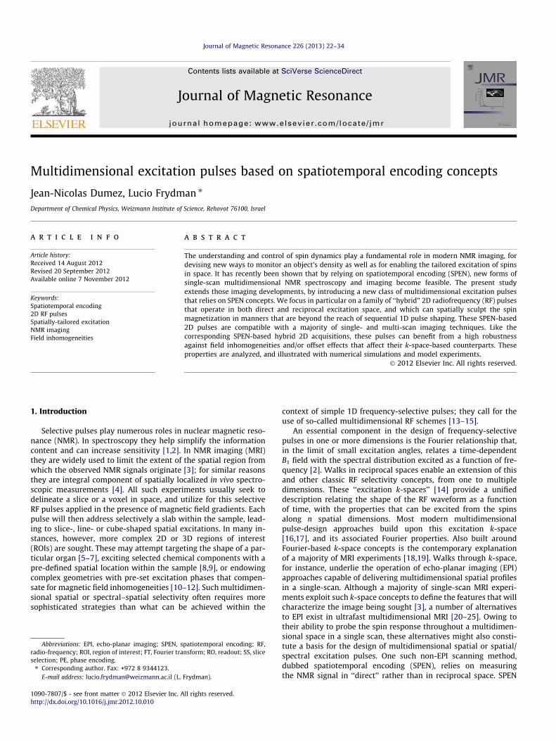
Fig. 1. One-dimensional excitation in direct space using a linearly frequency-swept pularrow, and of uniform (a and c) or shaped (b and d) amplitude, excited using either a conRF phase and the gradient amplitude are shown in the first, second and third row respcalculated using Bloch simulations, are shown in the fourth row. The time-bandwidth prresulting in the excitation of periodic sidebands with a replication length of (Ne/Q)ROI =
seen as operating in both direct and reciprocal spaces, are compat-ible with SPEN-based as well as with conventional k-space-basedNMR imaging. In the latter, more usual case, attention is placedon a self-unfolding property of these new pulses that endows themwith a high robustness against field inhomogeneities and/or chem-ical shift offsets.
2. Theory
2.1. RF spatial sculpting using SPEN concepts in one dimension
NMR imparts 1D spatial selectivity by applying a shaped RFwaveform in unison with an external magnetic field gradient. Intypical excitation schemes RF pulses address all the frequencyelements within a targeted ROI simultaneously; in SPEN-orientedexcitation pulses, spins across the sample will be addressedsequentially by the combined action of the magnetic field gradientand of a frequency-swept RF. In the simplest description of these
0 1
−2 0 2OI
0 1e / Te
−2 0 2
(c) Discrete uniform chirp pulse
(d) Discrete shaped chirp pulse
ROI ROI
se. Examples are given for a region of interest of length ROI, indicated by a doubletinuous (a and b) or a discretized (c and d) pulse. In each case, the RF amplitude, theectively. The magnitudes of the transverse magnetization at the end of the pulseoduct of the pulses are Q = 40 for all cases; the discretized pulses use Ne = 80 steps2ROI.
,,
24 J.-N. Dumez, L. Frydman / Journal of Magnetic Resonance 226 (2013) 22–34
pulses spins are acted upon instantaneously when the carrier fre-quency of a linearly-swept (chirped) RF matches their resonancefrequency, and precess freely otherwise [27]. When a constant-amplitude profile is used the ensuing RF waveform can be writtenin the usual rotating frame:
B1ðtÞ ¼ B01 exp i Oi;et þ Ret2
2þ /0
� �� �¼ B0
1 exp½i/e�; ð1Þ
where B01, /0, Re and Oi,e are the RF amplitude, an arbitrary initial
phase (set henceforth to zero), the constant sweep rate and the ini-tial carrier frequency offset of the excitation pulse, respectively.This approach leads to a uniform excitation of an initially longitudi-nal magnetization Mz, into a post-excitation transverse magnetiza-tion ||M+||. The effective nutation angle 0 6 h 6 p associated to thissweep can be set according to the B0
1 value chosen, and the post-excitation phase of the spins can be well approximated by the qua-dratic form [27–31]:
/excðyÞ ¼ � cGeð Þ2
2Re
!y2 þ cGe Te þ
Oi;e �XRe
� �� �y
þ XTe �ðOi;e �XÞ2
2Re� p
2
!; ð2Þ
where Ge is the amplitude of a gradient assumed applied along they-axis, Te is the overall duration of the pulse, and X is a site-specificfrequency offset associated to chemical shift or field inhomogeneityeffects. In practice, the amplitude modulation of the frequency-swept pulse is not strictly constant, as some smoothing is usuallyapplied to avoid the ringing induced by the finite duration of thepulse [32,33]. Such smoothing of the waveform can be achievedwith a WURST-like envelope [33], transitioning outside the targetedROI and leaving the excitation phase in Eq. (2) virtually unchanged.If the effects of the a priori unknown offset X can be disregarded (orif its value as a function of y is known, cf. Refs. [24,26]) the excita-tion of a sculpted ||M+||(y) is straightforward, simply by imparting atime-dependency B0
1ðtÞ to the amplitude of the chirp pulse as the RFaddresses various y-dependent positions, as illustrated in Fig. 1aand b. At times t this pulse will impart on the corresponding y(t)
yðtÞ ¼ ðOi;e �XÞ þ RetcGe
; ð3Þ
a nutation angle h(t), depending on the shape given to B01.
Whereas continuous versions of these frequency-swept pulsescan impart nearly ideal profiles, various properties of the multidi-mensional schemes described below will require considering thebehavior of these RF pulses upon discretization. Discretization isnowadays an inherent feature of any shaped RF pulse, dictatedby hardware-based shaping constraints. What we consider here,however, are the particular effects that arise upon replacing the fi-nely modulated RF pulse acting in the presence of a constant gra-dient, by an alternation of Ne square pulses acting in the absenceof gradients interleaved with Ne gradient ‘‘blips’’ acting on freelyevolving spins between the pulses. Both of these events are there-fore clocked out at a common rate Dt�1 = Ne/Te. The integrated areaand the phase of the jth square pulse will be given by B0
1ðtjÞTe=Ne
and /j, respectively, where tj = jDt; and the blipped gradients willbe assumed identical and square with integrated areas Dke � (cGe-
Te)/Ne each. Fig. 1c and d illustrates this discretization process aswell as its effects on the ensuing sculpting. The main consequenceof this discretization is the periodic replication of the excited mag-netization profile, as can be seen by comparison against Fig. 1a andb. These replicas become increasingly closer as the number of Ne
events decreases. This effect reflects the fact that any twospin-packets for which the gradient-derived precession phase
varies by a multiple of 2p in any given Dt step will appear indistin-guishable when acted upon by the subsequent RF pulse. Noticethat in contrast to traditional DANTE [34] or to ‘‘gapped’’ [35]pulses, the precession and nutation steps are entirely separatedin the implementation just described; this is similar to what hasbeen recently described in the PINS approach [36], and explainsthe identical intensities elicited (at least in such fully broadbandsimulations unaffected by instrumental limitations) by all excita-tion center-/side-bands.
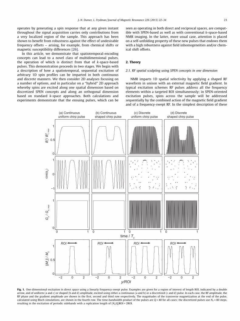
Fig. 2 expands on another aspect of the magnetization profilethat will be excited by a discretized chirp pulse: as predicted forthe continuously swept case (Eq. (2)) this excitation will also inthis case impart an approximately quadratic phase profile for thetransverse magnetization – not only for the centerband being ad-dressed, but also for the excitation sidebands that flank it. Assum-ing for simplicity that these excitation sidebands fall outside thetargeted ROI and can thereby be ignored, the originating signalwould still be ready for SPEN-based MRI but not in general forconventional k-space-based acquisitions. Indeed, signals in SPENexperiments originate from points of the sample that correspondto an extremum of the spatially varying parabolic phase[22–24,28]; this ‘‘stationary point’’ will move as an acquisitiongradient Ga is applied, rasterizing the response of the full sampleas the acquisition time reaches Ta = |GeTe/Ga|. By contrast, the par-abolic phase associated to a continuous or discretized chirp pulseis not suitable in general for a Fourier-based MRI. Fourier transfor-mation of the signal acquired from a magnetization with aquadratic-phase, a so-called ‘‘pseudo-echo’’ [37], will only yieldan image without aliasing if the quadratic phase does not involvefrequencies larger than cGaFOV, where Ga is the acquisitiongradient and FOV the field of view [37]. A simple strategy forremoving this quadratic phase imparted by an excitation chirppulse – while preserving its B0
1-imparted profile – consists of fol-lowing the excitation by a suitably defined frequency-swept refo-cusing pulse [28–30,32]. Pairs of frequency-swept pulses arefrequently used for volume selection in localized spectroscopy[38]; generalized hyperbolic secant and adiabatic SLR pulses havealso been paired to perform slice selection in imaging experiments[39,40]. The phase accrued after applying such an adiabatic 180�swept pulse can be written as [28]:
/ref ðyÞ ¼ � /excðyÞ þ � ðcGrÞ2
Rr
!y2 þ cGr Tr þ
2ðOi;r �XÞRr
� �� �y
þ XTr �ðOi;r �XÞ2
Rr
!; ð4Þ
where Tr, Rr, Oi,r and Gr are, respectively, the duration, the sweeprate, the initial carrier frequency and the concurrent gradient asso-ciated with the 180� refocusing pulse; /exc is an initial phase givenby either Eq. (2) or by a ‘‘discretized’’ version of thereof. For simplic-ity, we shall assume here that the refocusing pulse is always playedout continuously. When this refocusing chirp pulse follows the exci-tation chirp pulse and addresses the same region of interest, settingTeGe = 2TrGr will entirely remove the quadratic phase dependence ofthe /ref in Eq. (4). In particular, Fig. 2 demonstrates how the simplechoice of parameters Te = 2Tr and Ge = Gr succeeds in removing thecontribution of the quadratic phase off the targeted ROI, whichtherefore ends up ready to be analyzed by conventional k-spaceFourier imaging. Notice as well that as a result of the double-sweep:(i) the linear phase contribution previously arising from the chem-ical shifts is removed; (ii) if/when using a discretized version of the90� chirp pulse, the quadratic phase contributions that previouslyaffected the excitation sidebands will be removed by the 180�post-excitation adiabatic sweep only for the fraction of the side-bands that is swept over by the refocusing pulse.
−2 0 2
y/ROI
−2.4 −2 −1.6 −0.4 0 0.4
y/ROI1.6 2 2.4
−2 0 20
0.5
1
y/ROI
−2.4 −2 −1.60
150
300
φ (°
)
−0.4 0 0.4
y/ROI1.6 2 2.4
RFG
RFG
Te/2G Ge
(a) Excitation chirp pulse Ge
||M+|
| / M
0
(b) Excitation chirp and matched-phase
refocusing chirp pulsekrefkrefTe Te
90˚ 90˚
180˚
e
Fig. 2. Bloch-simulations of the transverse magnetizations excited by a chirp pulse (a), and by the combination of excitation and refocusing chirp pulses (b). Pulse sequencesare shown in the first row; the magnitude and phase of the transverse magnetization are shown in the second and third row, respectively. The excitation chirp pulse has atime-bandwidth product Q = 100 and is assumed either continuous (green traces) or discretized with Ne = 200 steps (blue). Notice that discretization results in the excitationof periodic sidebands with a replication length of (Ne/Q)ROI = 2ROI. The two pulses are assumed applied under identical gradient amplitudes and sweep over identical regionsof length ROI. The duration of the (continuous) refocusing chirp pulse is half that of the excitation chirp pulse, so as to cancel the quadratic phase of the centerband at itsconclusion. An additional gradient lobe of area kref = �GeTe/2 is inserted to cancel the linear phase of the centerband. The distortions of the ROI in (b) corresponds to thetransition regions of the refocusing pulse, and their unwanted contributions to the signal can be suppressed with crusher gradients. (For interpretation of the references tocolor in this figure legend, the reader is referred to the web version of this article.)
J.-N. Dumez, L. Frydman / Journal of Magnetic Resonance 226 (2013) 22–34 25
2.2. Discretized SPEN-based RF pulses: dealing with excitationsidebands
The existence of excitation sidebands can have important con-sequences. In usual experiments the MRI signal to be acquiredshould originate only from the targeted region of interest; i.e., fromthe centerband. For either k-space-based or SPEN-based MRIexperiments, the signal eventually detected after a discretizedexcitation can in principle include contributions arising from unde-sirable excitation sidebands. One possibility to overcome this prob-lem is to presaturate potential sources of interference arising fromvoxels outside the ROI. Alternatives include designing the discret-ized pulse so that its excitation sidebands fall outside the sample,or applying a refocusing pulse selectively on the centerband. Allsuch approaches are of common use, particularly when dealingwith multidimensional RF pulse designs that often rely on discret-ization along only one of the sample’s axes [16,41]. Requesting thatthe excitation sidebands fall outside a pre-defined ROI sets boundson the properties of the discretized RF pulse and of its associatedgradient. For the SPEN-based pulses considered here, a given chirpexcitation bandwidth Dm = (Of,e � Oi,e)/2p will define the ROI as2pDm/cGe. The separation DL at which the excitation sideband willappear replicated can in turn can be related to the interval Dt = Te/Ne that separates the subpulses of the discretized chirp pulse,according to cGeDL = 2p/Dt. The condition for the excitation side-bands to appear clearly separated from the centerband is thusDL > ROI, or alternatively
Ne
Dm � Te> 1() Ne > Q ¼ Dm � Te: ð5Þ
Eq. (5) states that the number of subpulses in the discretizedpulse should be larger than the time-bandwidth product Q = Dm � Te
pulse. This time-bandwidth product is a dimensionless measure of
the pulse’s performance: for a chirp pulse, the selectivity of thepulse improves as Q increases. Also the curvature of the qua-dratic-phase parabola imprinted on the spins by a swept pulse isproportional to Q. In SPEN experiments time-bandwidth productsin the 50–100 range are not unusual; such a high number of dis-cretized subpulses may not be realistic in most multidimensionalpulse contexts. Lower Q values can often be tolerated, although ifQ < 20 the assumption of a progressive excitation underlying theuse of chirped excitations begins to break down. It is also worthpointing out that although low Q values were a limitation in theoriginal implementation of spatiotemporal encoding [22–24], im-proved reconstruction schemes now make it possible to recover aspatial resolution that is given by the number of acquired pointsrather than
ffiffiffiffiQp
[42].As mentioned above, the main complication associated with
excitation sidebands arises when one cannot avoid their overlap-ping with the central ROI being targeted. One possibility to circum-vent these limitations without employing an inordinately highnumber of Ne steps or very long pulse lengths Te, is by reducingthe chirped bandwidth Dm. For a given ROI Eq. (5) indicates thatthis can be achieved by reducing the associated gradient amplitudeGe such that
G <2pNe
cROI � Te: ð6Þ
Similar bounds on the gradient amplitude are known for thecase of Fourier-based discrete pulses [16], and like in those in-stances their adoption poses a problem: weakening gradients asdemanded by Eq. (6) may make the pulse susceptible to distor-tions, particularly those arising from susceptibility and chemical-shift effects. These effects become secondary if strong gradientscan be used; in the case of k-space-based pulses, it is possible to
26 J.-N. Dumez, L. Frydman / Journal of Magnetic Resonance 226 (2013) 22–34
deal with the ensuing sideband/centerband overlaps that thenarise by performing multiple acquisitions, which are combined torecover a centerband-only signal [6,43].
For discretized SPEN pulses, the contribution of the centerbandand the sidebands can under certain conditions be separated in asingle conventional scan – even when dealing with cases of signif-icant overlap. This in turn opens the possibility to use intense gra-dients, endowing the ensuing SPEN-based strategy with highimmunity against undesirable frequency offsets. This will be ameaningful consideration in the design of 2D pulses, and thereforeit is convenient to consider its physical basis for the simpler one-dimensional cases. Under the effects of a discretized excitation,the total magnetization excited by a pulse can be quite complex.A substantial simplification results if the flip angle remains smallenough for all positions. In such instances the total magnetizationis conveniently described as a sum over bands:
mag
nitu
de
-32 0 32
mag
nitu
de
k/δk
(a) Refocused SPEN scheme
-128 0 128
-32 0 32
mag
nitu
de
(e) Discrete excitation chirp pulse and con unfolding of the region of interest by filt
(d) Discrete excitation chirp pulse and con results for a case with three overlapping
(c) Continuous excitation and continuous r
Ga
ACQ
Ta
RF/ADCG
Te/2Ge GekrefTe
90˚
180˚
signal
signal
signal
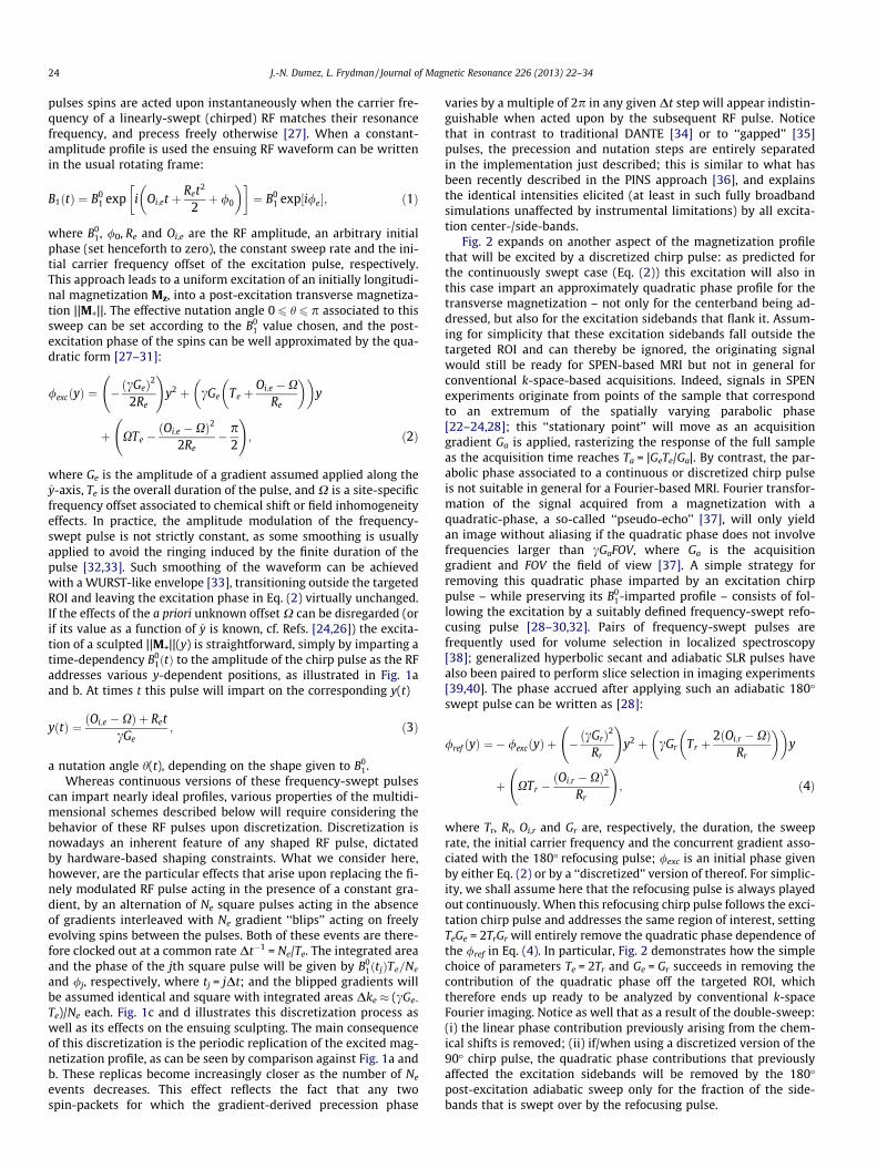
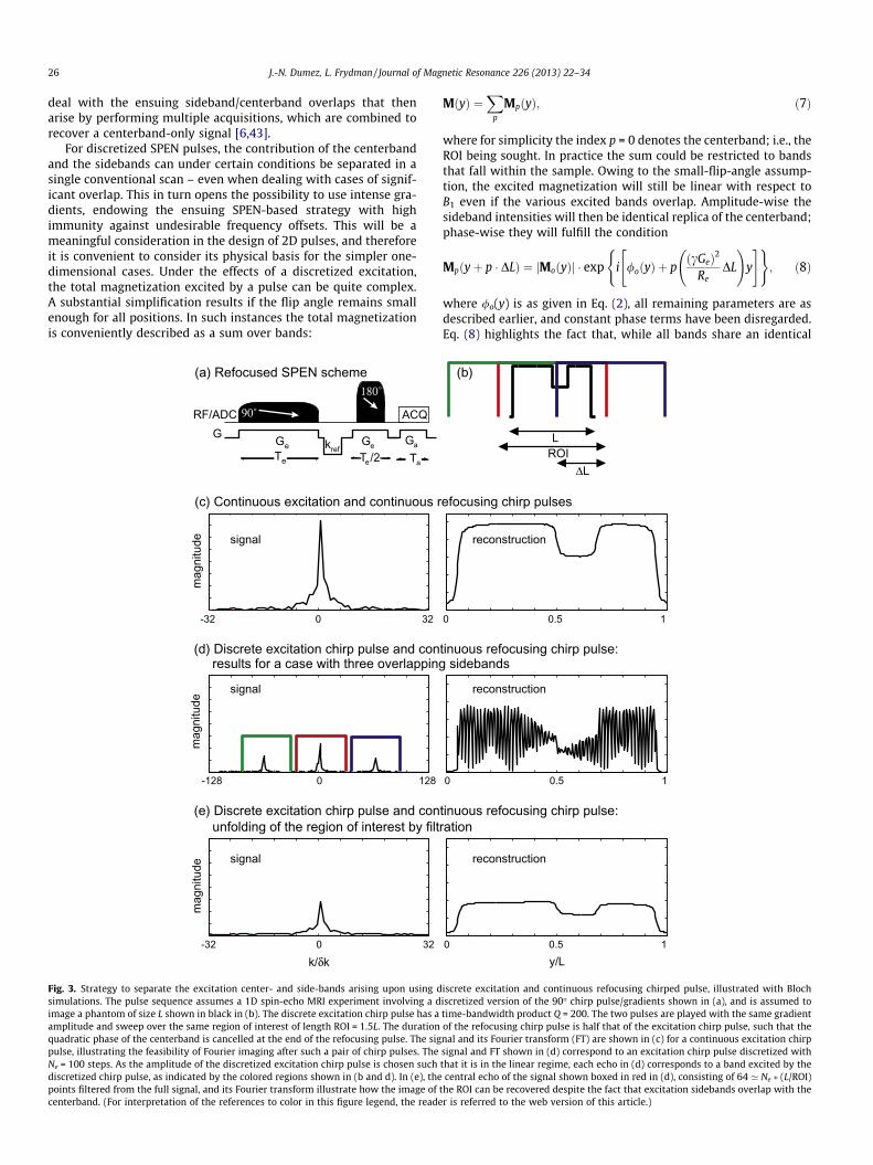
Fig. 3. Strategy to separate the excitation center- and side-bands arising upon using dsimulations. The pulse sequence assumes a 1D spin-echo MRI experiment involving a dimage a phantom of size L shown in black in (b). The discrete excitation chirp pulse has aamplitude and sweep over the same region of interest of length ROI = 1.5L. The durationquadratic phase of the centerband is cancelled at the end of the refocusing pulse. The sigpulse, illustrating the feasibility of Fourier imaging after such a pair of chirp pulses. TheNe = 100 steps. As the amplitude of the discretized excitation chirp pulse is chosen suchdiscretized chirp pulse, as indicated by the colored regions shown in (b and d). In (e), thepoints filtered from the full signal, and its Fourier transform illustrate how the image ofcenterband. (For interpretation of the references to color in this figure legend, the reade
MðyÞ ¼X
p
MpðyÞ; ð7Þ
where for simplicity the index p = 0 denotes the centerband; i.e., theROI being sought. In practice the sum could be restricted to bandsthat fall within the sample. Owing to the small-flip-angle assump-tion, the excited magnetization will still be linear with respect toB1 even if the various excited bands overlap. Amplitude-wise thesideband intensities will then be identical replica of the centerband;phase-wise they will fulfill the condition
Mpðyþ p � DLÞ ¼ jMoðyÞj � exp i /oðyÞ þ pðcGeÞ2
ReDL
!y
" #( ); ð8Þ
where /o(y) is as given in Eq. (2), all remaining parameters are asdescribed earlier, and constant phase terms have been disregarded.Eq. (8) highlights the fact that, while all bands share an identical
0 0.5 1
y/L
(b)
(e)
0 0.5 1
0 0.5 1
LROI
tinuous refocusing chirp pulse: ration
tinuous refocusing chirp pulse: sidebands
efocusing chirp pulses
ΔL
reconstruction
reconstruction
reconstruction
iscrete excitation and continuous refocusing chirped pulse, illustrated with Blochiscretized version of the 90� chirp pulse/gradients shown in (a), and is assumed totime-bandwidth product Q = 200. The two pulses are played with the same gradientof the refocusing chirp pulse is half that of the excitation chirp pulse, such that thenal and its Fourier transform (FT) are shown in (c) for a continuous excitation chirpsignal and FT shown in (d) correspond to an excitation chirp pulse discretized withthat it is in the linear regime, each echo in (d) corresponds to a band excited by thecentral echo of the signal shown boxed in red in (d), consisting of 64 ’ Ne � (L/ROI)
the ROI can be recovered despite the fact that excitation sidebands overlap with ther is referred to the web version of this article.)
0
1
kx
y(a) kx / y trajectory
(b) Hybrid 2D pulse with a uniform enveloppe in the “slow” dimension and sinc subpulses
in the “fast” dimension
B 1 / B
1, m
ax
“fast” dimension“slo
w” d
imen
sion
J.-N. Dumez, L. Frydman / Journal of Magnetic Resonance 226 (2013) 22–34 27
quadratic contribution in their phases, they do differ by a linearphase coefficient. This allows one to separate the contribution ofthe centerband to the signal from that of the sidebands: if, followingthe excitation process, the quadratic phase terms are removed (forinstance by the application of a suitable 180� adiabatic chirp pulseas explained earlier) each band will then form its own individualecho at a distinct location in k-space. Fig. 3 illustrates a way ofachieving and exploiting this, for the case of overlapping bands aris-ing due to a discrete excitation that breaks the G < 2pNe
cROI�Tecondition
given in Eq. (6) (i.e., for a case where the centerband and the side-bands overlap). In this example the post-excitation 180� refocusingpulse removed the quadratic phase for the center- and for the over-lapping side-bands; as per Eq. (8), these bands will still differ fromone another by a linear term of the form p ðcGeÞ2
ReDL
� �y ¼ pNe
yROI
. As
a result of this difference a linear gradient applied before or afterthe refocusing pulse will lead to a distinct echo for each band; thecontribution of the centerband can thus be retrieved by a simplek-domain weighting fashion, despite the fact that its spectrum over-laps with that of the sidebands. Notice that this approach provides away to increase the gradient amplitude Ge associated with the spa-tial selectivity and thus to improve the robustness of the RF pulseagainst field inhomogeneities. This improvement, however, comesat a price in sensitivity: preserving the linear approximation impli-cit in Eq. (7) implies that only a fraction of the magnetization in theROI being excited, corresponds to the undistorted centerband beingsought. The remaining portion of the magnetization corresponds toharmonics of the excitation sidebands, that overlap with the center-band and whose imaging information is not faithful.
−1
0
1
0
1
Gy / G
y, m
ax
0 0.5 1
−1
0
1
Gx / G
x, m
ax
time / Te
cos(
φ e)
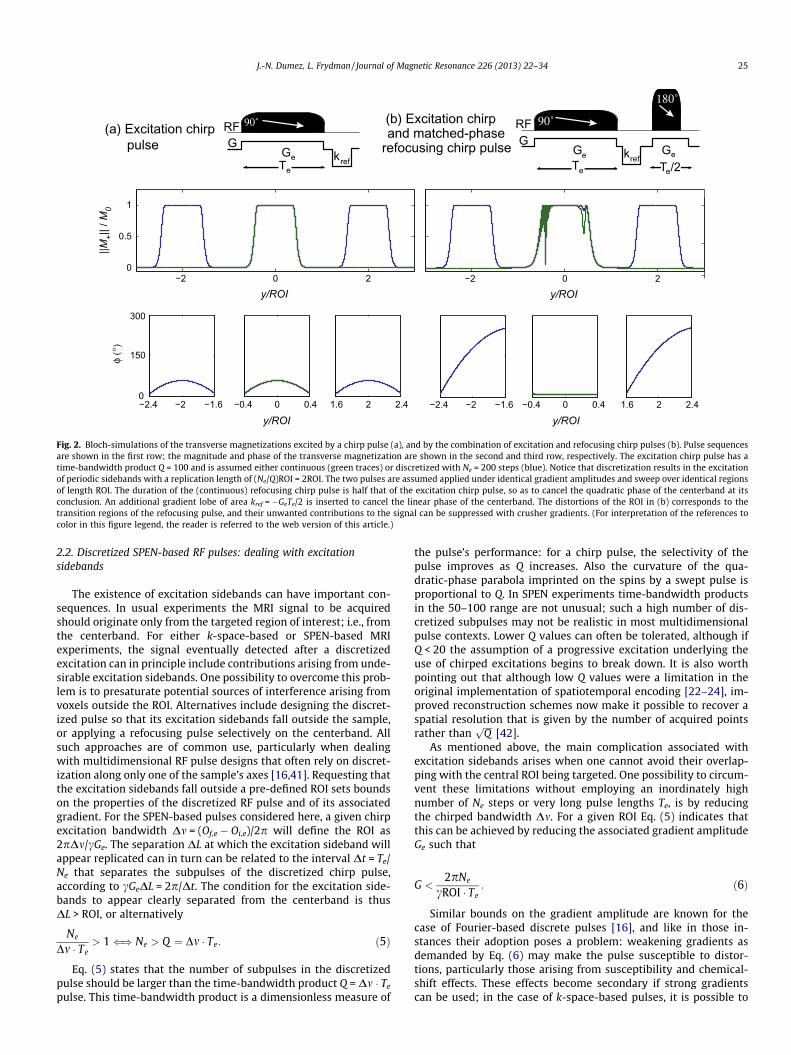
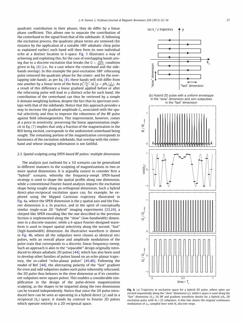
Fig. 4. (a) Trajectory in excitation space for a hybrid 2D pulse, where spins areexcited sequentially along the ‘‘slow’’ dimension (y), while k-space is used along the‘‘fast’’ dimension (kx). (b) RF and gradient waveform details for a hybrid y/kx 2Dexcitation pulse with Ne = 25 subpulses. A thin line shows the original continuousmodulation of /e, sampled here with Ne discrete steps.
2.3. Spatial sculpting using SPEN-based RF pulses: multiple dimensions
The analysis just outlined for a 1D scenario can be generalizedin different manners to the sculpting of magnetizations in two ormore spatial dimensions. It is arguably easiest to consider first a‘‘hybrid’’ scenario, whereby the frequency-swept SPEN-basedstrategy is used to shape the spatial profile along one dimension,while a conventional Fourier-based analysis imparts the excitationshape being sought along an orthogonal dimension. Such a hybriddirect-plus-reciprocal excitation space can, for example, be ex-plored using the blipped Cartesian trajectory illustrated inFig. 4a, where the SPEN dimension is the y spatial axis and the Fou-rier dimension is x. In practice, and in the spirit of conceptuallysimilar single-scan 2D ‘‘hybrid’’ imaging experiments [23,24], achirped-like SPEN encoding like the one described in the previousSection is implemented along the ‘‘slow’’ (low-bandwidth) dimen-sion in a discrete manner, while a k-space Fourier-designed wave-form is used to impart spatial selectivity along the second, ‘‘fast’’(high-bandwidth) dimension. An illustrative waveform is shownin Fig. 4b, where all the subpulses were chosen as identical sincpulses, with an overall phase and amplitude modulation of thepulse train that corresponds to a discrete, linear frequency-sweep.Such an approach is akin to the ‘‘separable’’ design originally intro-duced to obtain adiabatic 2D pulses [44], which has also been usedto develop other families of pulses based on an echo-planar trajec-tory, the so-called ‘‘echo-planar pulses’’ [45,46]. Following themodel of Ref. [44], the alternating polarity of the ‘‘fast’’ gradientfor even and odd subpulses makes each pulse inherently refocused;the 2D pulse thus behaves in the slow dimension as if its constitu-ent subpulses were square pulses. This enables a considerable sim-plification in the design of the pulse-driven magnetizationsculpting, as the shapes to be imparted along the two dimensionscan be treated independently. Notice that since the 2D pulse intro-duced here can be seen as operating in a hybrid direct (y) and in areciprocal (kx) space, it stands by contrast to Fourier 2D pulseswhich operate entirely in a 2D reciprocal space.
28 J.-N. Dumez, L. Frydman / Journal of Magnetic Resonance 226 (2013) 22–34
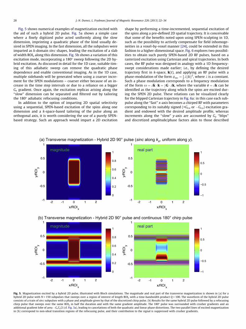
Fig. 5 shows numerical examples of magnetization excited withthe aid of such a hybrid 2D pulse. Fig. 5a shows a simple casewhere a finely digitized pulse acted uniformly along the slowdimension, imprinting a quadratic phase of the kind usually de-sired in SPEN imaging. In the fast dimension, all the subpulses wereimparted as k-domain sinc shapes, leading the excitation of a slabof width ROIx along this dimension. Fig. 5b shows a variation of thisexcitation mode, incorporating a 180� sweep following the 2D hy-brid excitation. As discussed in detail for the 1D case, suitable tim-ing of this adiabatic sweep can remove the quadratic phasedependence and enable conventional imaging. As in the 1D case,multiple sidebands will be generated when using a coarser incre-ment for the SPEN modulations – coarser either because of an in-crease in the time step intervals or due to a reliance on a biggerGe gradient. Once again, the excitation replicas arising along the‘‘slow’’ dimension can be separated and filtered out by tailoringthe 180� adiabatic refocusing conditions.
In addition to the option of imparting 2D spatial selectivityusing a sequential, SPEN-based excitation of the spins along onedimension and a k-space-based tailoring of the pulse along anorthogonal axis, it is worth considering the use of a purely SPEN-based strategy. Such an approach would impart a 2D excitation
0
0.2
0.4
0.6
0.8
1
(a) Transverse magnetization - Hybrid 2D 90°
(b) Transverse magnetization - Hybrid 2D 90° p
0
0.2
0.4
0.6
0.8
1
magnitude
magnitude
Fig. 5. Magnetization excited by a hybrid 2D pulse, illustrated with Bloch simulations.hybrid 2D pulse with N = 150 subpulses that sweeps over a region of interest of length Rconsists of a train of sinc subpulses with a phase and amplitude given by that of the discrchirp pulse that sweeps over the same ROIy in half the duration and with the same gadditional gradient lobe of area �GeTe/2 (cf. Fig. 3a), leading to cancelations of both the quin (b) correspond to non-ideal transition regions of the refocusing pulse, and their cont
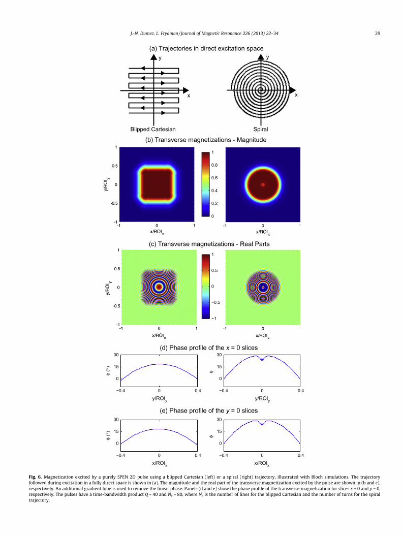
shape by performing a time-incremented, sequential excitation ofthe spins along a pre-defined 2D spatial trajectory. It is conceivablethat some of the benefits noted upon using SPEN-sculpting in 1D,such as the possibility to actively compensate for field inhomoge-neities in a voxel-by-voxel manner [24], could be extended in thisfashion to a higher-dimensional space. Fig. 6 explores two possibil-ities to obtain such purely SPEN-based 2D RF pulses, based on arasterized excitation using Cartesian and spiral trajectories. In bothcases, the RF pulse was designed in analogy with a 1D frequency-swept considerations made earlier; i.e., by defining the desiredtrajectory first in k-space, k(t), and applying an RF pulse with aphase-modulation of the form /exc ¼ 1
2 kjjkjj2, where k is a constant.Such a phase modulation corresponds to a frequency modulationof the form x ¼ k _k � k ¼ cG � kk, where the variable r ¼ kk can beidentified as the trajectory along which the spins are excited dur-ing the SPEN 2D pulse. These relations can be visualized clearlyfor the blipped Cartesian trajectory in Fig. 6a: in this case each sub-pulse along the ‘‘fast’’ x-axis becomes a chirped RF with parameterscorresponding to its suitably signed (+Ge,x or �Ge,x) excitation gra-dient and endowed with the desired amplitude profile, whereasincrements along the ‘‘slow’’ y-axis are accounted by Gy ‘‘blips’’and discretized amplitude/phase factors akin to those described
−1
−0.5
0
0.5
1
pulse (sinc along kx, uniform along y).
ulse and continuous 180° chirp pulse
−1
−0.5
0
0.5
1
real part
real part
The magnitude and real part of the transverse magnetization is shown in (a) for aOIy with a time-bandwidth product Q = 100. The waveform of the hybrid 2D pulse
etized chirp pulse. (b) Results for the same hybrid 2D pulse followed by a refocusingradient amplitude. The 180� pulse was surrounded with crusher gradients and anadratic and linear phase distortions. The two parallel lines of excited magnetization
ribution to the signal is suppressed with crusher gradients.
−0.4 0 0.4
0
15
30
y/ROIy y/ROIy
φ (°
)
−0.4 0 0.4
0
15
30
x/ROIx x/ROIx
φ (°
)
0
15
30
φ
0
15
30
φ
x
y
x
y
−0.4 0 0.4
−0.4 0 0.4
(d) Phase profile of the x = 0 slices
SpiralBlipped Cartesian
−1
−0.5
0
0.5
1
0
0.2
0.4
0.6
0.8
1
(a) Trajectories in direct excitation space
(e) Phase profile of the y = 0 slices
(b) Transverse magnetizations - Magnitude
(c) Transverse magnetizations - Real Parts
Fig. 6. Magnetization excited by a purely SPEN 2D pulse using a blipped Cartesian (left) or a spiral (right) trajectory, illustrated with Bloch simulations. The trajectoryfollowed during excitation in a fully direct space is shown in (a). The magnitude and the real part of the transverse magnetization excited by the pulse are shown in (b and c),respectively. An additional gradient lobe is used to remove the linear phase. Panels (d and e) show the phase profile of the transverse magnetization for slices x = 0 and y = 0,respectively. The pulses have a time-bandwidth product Q = 40 and Ne = 80, where Ne is the number of lines for the blipped Cartesian and the number of turns for the spiraltrajectory.
J.-N. Dumez, L. Frydman / Journal of Magnetic Resonance 226 (2013) 22–34 29
30 J.-N. Dumez, L. Frydman / Journal of Magnetic Resonance 226 (2013) 22–34
above for the hybrid 2D (y/kx) pulse. Notice that due to this discret-ization procedure, the various sideband-related arguments men-tioned for the hybrid case are also relevant here.
The sequential excitation of the spins along a spiral trajectorycan be understood in a similar manner. For an Archimedean spiralwith N turns and total duration T, depicted on the right-hand sideof Fig. 6b, the k-space trajectory can be written:
kx ¼ cG0t cosðxGtÞ; ky ¼ cG0t sinðxGtÞ; ð9Þ
where G0 is a constant and a constant angular velocity has beenused for simplicity. This results in a demand for the synthesis of aquadratic RF excitation phase
/ ¼ 12cG0v0t2; ð10Þ
where v0 is a constant representing an ‘‘average velocity’’ withwhich points being addressed at a given time move away from
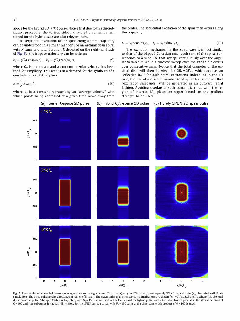
Fig. 7. Time evolution of excited transverse magnetizations during a Fourier 2D pulse (asimulations. The three pulses excite a rectangular region of interest. The magnitudes of thduration of the pulse. A blipped Cartesian trajectory with Ne = 150 lines is used for the FoQ = 100 and sinc subpulses in the fast dimension. For the SPEN pulse, a spiral with Ne =
the center. The sequential excitation of the spins then occurs alongthe trajectory:
rx ¼ v0t cosðxGtÞ; ry ¼ v0t sinðxGtÞ: ð11Þ
The excitation mechanism in this spiral case is in fact similarto that of the blipped Cartesian case: each turn of the spiral cor-responds to a subpulse that sweeps continuously over the angu-lar variable h, while a discrete sweep over the variable r occursover consecutive arms. Notice that the total diameter of the ex-cited disk will then be given by 2RX = 2Tv0, which acts as an‘‘effective ROI’’ for such spiral excitations. Indeed, as in the 1Dcase, the use of a discrete number N of spiral turns implies that‘‘excitation sidebands’’ will be generated in an outward radialfashion. Avoiding overlap of such concentric rings with the re-gion of interest 2RX places an upper bound on the gradientstrength to be used
), a hybrid 2D pulse (b) and a purely SPEN 2D spiral pulse (c), illustrated with Bloche transverse magnetizations are shown for t = Te/3, 2Te/3 and Te, where Te is the totalurier and the hybrid pulse, with a time-bandwidth product in the slow dimension of150 turns and a time-bandwidth product of Q = 100 is used.

(b) (c)
RF/ADC
GSS
2D
Gss
ACQ
Te/2
GRO/PE
GSPEN/RONe/2
<GSPEN>
GRO
GSPEN
eGRO
a
Te Ta
(a) Common pulse scheme 180˚90˚
180˚
Fourier excitation (fast) - Fourier detection (PE)
tion
(RO
)
J.-N. Dumez, L. Frydman / Journal of Magnetic Resonance 226 (2013) 22–34 31
G0 <2pNc2RXT
: ð12Þ
This constraint is akin to the one stated in Eq. (6) for the 1D dis-crete chirped excitation case. Similarly, a time-bandwidth productcan be defined as Q = 2TeG0RX.
To conclude these considerations, it is enlightening to comparethe time progression with which k-space, hybrid k/r-space and thepurely-SPEN spiral pulses just treated, will excite an arbitrary rect-angular shape in two dimensions. Presented as Supplementarymaterial is an animated version of these events for a simple shape;Fig. 7 summarizes shots taken 33%, 66% and 100% throughout thecourse of each of these pulses. These plots evidence that whereasa classic k-space pulse excites the high-frequency and subse-quently all gross features of the shape rapidly, and then invests asubstantial part of the conclusion of pulse to sculpt the finer fea-tures globally, the spatially encoded pulses literally rasterize theexcitation sculpting throughout the course of their frequencysweeps.
3. Methods
Experiments assaying the various considerations of the previ-ous Section were carried out, focusing in particular on examiningthe performance of the hybrid 2D pulse vis-à-vis its classic k-space counterpart. These data were collected at 7 T on a VarianVNMRS 300/89 vertical-bore microimaging system (Varian asso-ciates, Palo Alto, CA) using a Millipede� probe. In all experimentsa water tube of 22 mm inner diameter was used as a phantom,on which either single-scan SPEN or multi-scan spin-echoimages were obtained after applying a selective 2D excitation.The generation of all RF and gradient waveforms needed to carryout these 2D pulse comparisons were written in Matlab� (TheMathworks, Natick, MA), and then exported into the NMRscanner where they were clocked out with 4 ls dwells. Data
(b) R
ecta
ngul
ar R
OI
RF/ADC
GRO
GSPEN
GSS
NacqNe
2D
(a) Pulse schemeACQ
Gss
180˚90˚
GRO
GSPEN
GRO
GSPEN
e a
Te Ta = Te
(c) S
tar-s
hape
d R
OI
Fourier
SPEN
Fig. 8. Single-scan 2D SPEN images obtained after applying hybrid 2D pulses thatexcite either rectangular (b) or star-shaped (c) ROIs. The pulse sequence is shown in(a), with RO, SPEN and SS denoting orthogonal gradients applied along the read-out(‘‘x’’), SPEN (‘‘y’’) and slice-select (‘‘z’’) directions. The 2D pulse had Ne = 70subpulses, a duration of Te = 30.8 ms and swept over ROIy = 20 mm with a time-bandwidth product Q = 50 in the slow dimension. The waveform was obtained byFT of the targeted pattern along the fast dimension, and by adjusting the phase andamplitude of each subpulse according to that of a discretized chirp pulse. A gradientGRO = 10 kHz mm�1 was used during the subpulses. 70 � 70 points were acquired ina single scan in a total time of Ta = 30.8 ms. ROIx was 2.5 cm in the readoutdimension. Following suitable rearrangement the signal was FT’d along the RO andsuper-resolved along the SPEN dimension.
processing was also performed off-line using custom-writtenMatlab routines.
The specific experimental implementations that were testedemployed the sequences shown in Figs. 8a and 9a. A central refo-cusing 180� pulse was used to select a slice of 4 mm thickness,with phase-encoding and prephasing gradients played on bothsides of this pulse, simultaneously with crusher gradients.During acquisition, the readout dimension was monitored with a250 kHz bandwidth. A detailed description of each RF pulse isgiven in the figure captions. When comparing the performance ofthe k-space vs. the hybrid 2D pulses a flyback design was usedfor both cases; i.e., RF was only played during odd k-lines (positivegradient of the zig-zag) in order to avoid timing imbalances. Suchtiming errors are most likely due to eddy-currents, which are notfully compensated on microimaging vertical hardware. In no casewere relaxation effects taken into account in the design of the RFwaveforms.
(d) (e)
FT: full fid FT: filtered echo of interest
SPEN
exc
itatio
n (s
low
) - F
ourie
r det
ec
Fig. 9. Conventional 2D spin-echo images obtained after a discretized 1D excitationchirp pulse (b and c) or a hybrid 2D excitation pulse (d and e) – followed in bothcases by a continuous refocusing chirp pulse – illustrating how undistorted ROIscan be recovered despite the presence of strongly overlapping excitation sidebands.The pulse sequence is shown in (a). Excitation chirp pulses were composed ofNe = 100 (b and c) or 50 (d and e) subpulses, with a duration of Te = 20.4 ms, sweptover a ROI = 3 cm with a time-bandwidth product Q = 200. A gradient GRO = 10kHz mm�1 was used during these subpulses, and their amplitudes were chosen tooperate in the linear regime. The excitation results were imaged by spin-echo MRIwith 256 � 32 points and a field of view of 3 � 3 cm2. The signal consists of severalechoes along the readout dimension; images (b and d) were obtained by Fouriertransforming the full signal in both dimensions after zero-filling to 256 � 128. Bycontrast, images (c and e) were obtained by filtering, respectively, 100 and 50points centered on the echo that correspond to the targeted ROI, zero-filling to128 � 128 points, and 2D FT.
32 J.-N. Dumez, L. Frydman / Journal of Magnetic Resonance 226 (2013) 22–34
4. Results and discussion
4.1. Hybrid 2D excitations and single-scan 2D SPEN imaging
One of the features associated to selective 2D excitations withhybrid pulses is the fact that the phase imparted will contain aquadratic dependence along the ‘‘slow’’ dimension. This makessuch pulses well suited to implement a SPEN-based detection;Fig. 8b shows a 2D image obtained in such way and in a single-scan: a hybrid 2D pulse with all the subpulses along the ‘‘fast’’dimension made of identical sinc profiles was applied, and theensuing excitation then monitored using single-scan 2D SPENMRI. The intrinsic resolution of these images was also enhancedby use of a super-resolution algorithm [42], and the acquisitionwas timed in order to record the full pseudo-echo in a fully refo-cused manner [26]. As explained earlier this SPEN NMR image doesnot require FT along the spatially encoded direction – only alongthe read-out axis. The rectangular regions selectively excited bythe sinc profiles are clear; notice as well that since parameterswere chosen such that the excitation sidebands fell outside thesample along the ‘‘slow’’ axis, only the center ROI was imaged.
This simple example suggests that hybrid 2D pulses could beused to add slice selectivity to existing SPEN imaging sequences.This option was explored in Ref. [47], albeit with a different ap-proach based on using profiles that could also be obtained by suit-able intersection of two 1D selectively excited regions. The 2Dhybrid SPEN pulse, by contrast, can also excite complex shapes thatdo not fulfill this simple property. This is illustrated in Fig. 8c,which shows the excitation of a star-shaped region and its subse-quent imaging with a single-scan SPEN sequence. Notice that,being a hybrid 2D pulse, the RF waveform that leads to this profilewas not obtained as the 2D Fourier transform of the region of inter-est. Instead, each subpulse is taken as a 1D Fourier transform of thecorresponding line in the targeted region, and the frequency sweepalong the ‘‘slow’’ dimension is then obtained by an overall phasemodulation of the train of subpulses.
For a given excitation pattern and a given bandwidth, the powerdeposition for a SPEN-based and for a Fourier-based 2D pulse willbe comparable. This reflects the fact that modulating a transversemagnetization with a quadratic-phase does not affect the energyrequired to excite it (see, e.g., Ref. [29]). Sequential excitation usinga frequency-sweep, however, leads to a decrease of the maximumRF amplitude of a hybrid 2D pulse compared to a Fourier-based 2D
(a) (b)
Fourier k-space 2D p
non-selectivepulse
Fourier excitation (fast) - Fou
Fig. 10. Conventional 2D spin-echo images obtained on a phantom consisting of five sma2D pulse based on a Fourier k-space design, and (c) a similar shape but obtained using180� chirp. The hybrid 2D pulse had a duration Te = 16.4 ms, Ne = 32 subpulses and swepThe Fourier 2D pulses had the same duration, number of subpulses, and ROI; its slowbandwidth in the fast dimension was identical for both pulses and arose from a GRO =128 � 64 points and a field of view of 2.5 � 2.5 cm. For (b and c), images were obtained bfilling to 128 � 128 points, and 2D FT.
pulse. SPEN-based 2D pulses should thus have the same compati-bility with the SAR requirements of in vivo imaging as conventional2D pulses.
4.2. Fourier imaging: hybrid 2D pulses incorporating a quadratic phaserefocusing
While the SPEN MRI experiment benefits in a natural way fromthe quadratic phase imparted by the hybrid 2D pulses just de-scribed, this pattern is not well suited for conventional k-spaceimaging. As discussed above, the use of a refocusing 180� chirppulse can remove such a quadratic phase. Besides enabling conven-tional imaging, this adiabatic sweep opens the possibility to sepa-rate the contribution of the main ROI from that of undesirableexcitation sidebands at an acquisition stage (Paragraph 2.2). Thisself-unfolding process is illustrated in Fig. 9 for both a discretized1D chirp pulse exciting the full 22 mm diameter sample (panels band c), and for a hybrid 2D pulse sculpting a triangle within thissample (panels d and e). The time-bandwidth product of thesediscretized chirp pulses was chosen to be ca. three times largerthan the number of subpulses, and the RF intensities were adjustedto remain in the linear excitation regime of the pulses. As a resultof this the imaging signals consisted of three well-separatedechoes, with each echo corresponding to a center/side-band. FTof the entire signal thus yields an interfering sum of multiplefolded bands along the ‘‘slow’’ dimension (Fig. 9, left-hand panels).However, if only a selected echo is transformed along the linesdescribed in Fig. 3, undistorted images of the ROIs can be recovered(Fig. 9, right-hand panels).
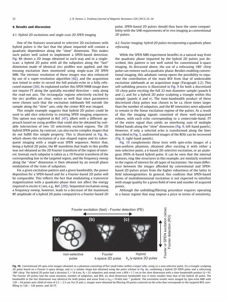
Fig. 10 complements these tests with spin-echo images of anon-uniform phantom, obtained after exciting it with either anon-selective pulse, a k-based 2D-selective excitation, or an analo-gous SPEN-/k-based hybrid pulse. It can be seen that the internalfeatures, ring-like structures in this example, are similarly resolvedin the region of interest for all types of excitations: the main differ-ence between the images afforded by conventional and SPEN-based 2D pulses arises from the higher robustness of the latter tofield inhomogeneities. In general, this confirms that SPEN-basedforms of multidimensional excitation is not expected to interferewith image quality for a given field of view and number of acquiredpoints.
Although the unfolding/filtering procedure requires operatingin a linear regime that may impose a price in terms of sensitivity,
(c)
ulseHybrid
kx /y-space 2D pulse
rier detection (PE)
Four
ier o
r SPE
N e
xcita
tion
(slo
w)
Fou
rier d
etec
tion
(RO
)
ll tubes within a larger tube, using (a) a non-selective pulse, (b) a triangle-sculptingthe pulse scheme in Fig. 8a, combining a hybrid 2D SPEN pulse and a refocusing
t over a ROI = 1.7 cm in the slow dimension with a time-bandwidth product Q = 93.-dimension bandwidth was 4 times smaller than that of the hybrid 2D pulse. The10 kHz mm�1 gradient. The excitation results were imaged by spin-echo MRI withy filtering 50 points centered on the echo that corresponds to the targeted ROI, zero-
J.-N. Dumez, L. Frydman / Journal of Magnetic Resonance 226 (2013) 22–34 33
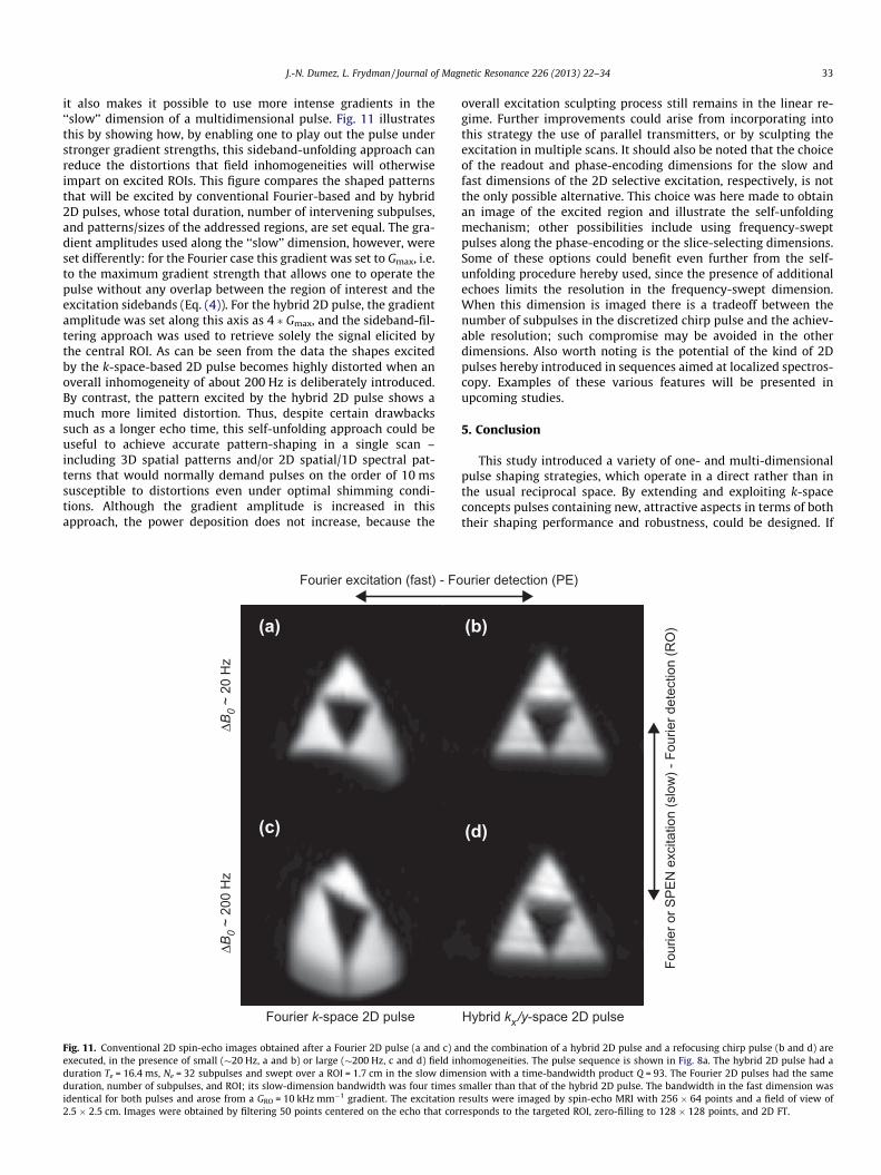
it also makes it possible to use more intense gradients in the‘‘slow’’ dimension of a multidimensional pulse. Fig. 11 illustratesthis by showing how, by enabling one to play out the pulse understronger gradient strengths, this sideband-unfolding approach canreduce the distortions that field inhomogeneities will otherwiseimpart on excited ROIs. This figure compares the shaped patternsthat will be excited by conventional Fourier-based and by hybrid2D pulses, whose total duration, number of intervening subpulses,and patterns/sizes of the addressed regions, are set equal. The gra-dient amplitudes used along the ‘‘slow’’ dimension, however, wereset differently: for the Fourier case this gradient was set to Gmax, i.e.to the maximum gradient strength that allows one to operate thepulse without any overlap between the region of interest and theexcitation sidebands (Eq. (4)). For the hybrid 2D pulse, the gradientamplitude was set along this axis as 4 � Gmax, and the sideband-fil-tering approach was used to retrieve solely the signal elicited bythe central ROI. As can be seen from the data the shapes excitedby the k-space-based 2D pulse becomes highly distorted when anoverall inhomogeneity of about 200 Hz is deliberately introduced.By contrast, the pattern excited by the hybrid 2D pulse shows amuch more limited distortion. Thus, despite certain drawbackssuch as a longer echo time, this self-unfolding approach could beuseful to achieve accurate pattern-shaping in a single scan –including 3D spatial patterns and/or 2D spatial/1D spectral pat-terns that would normally demand pulses on the order of 10 mssusceptible to distortions even under optimal shimming condi-tions. Although the gradient amplitude is increased in thisapproach, the power deposition does not increase, because the
ΔB0
~ 20
Hz
Fourier k-space 2D pulse
ΔB0
~ 20
0 H
z
(a)
(c)
Fourier excitation (fast) - Fo
Fig. 11. Conventional 2D spin-echo images obtained after a Fourier 2D pulse (a and c) aexecuted, in the presence of small (�20 Hz, a and b) or large (�200 Hz, c and d) field induration Te = 16.4 ms, Ne = 32 subpulses and swept over a ROI = 1.7 cm in the slow dimeduration, number of subpulses, and ROI; its slow-dimension bandwidth was four timesidentical for both pulses and arose from a GRO = 10 kHz mm�1 gradient. The excitation2.5 � 2.5 cm. Images were obtained by filtering 50 points centered on the echo that cor
overall excitation sculpting process still remains in the linear re-gime. Further improvements could arise from incorporating intothis strategy the use of parallel transmitters, or by sculpting theexcitation in multiple scans. It should also be noted that the choiceof the readout and phase-encoding dimensions for the slow andfast dimensions of the 2D selective excitation, respectively, is notthe only possible alternative. This choice was here made to obtainan image of the excited region and illustrate the self-unfoldingmechanism; other possibilities include using frequency-sweptpulses along the phase-encoding or the slice-selecting dimensions.Some of these options could benefit even further from the self-unfolding procedure hereby used, since the presence of additionalechoes limits the resolution in the frequency-swept dimension.When this dimension is imaged there is a tradeoff between thenumber of subpulses in the discretized chirp pulse and the achiev-able resolution; such compromise may be avoided in the otherdimensions. Also worth noting is the potential of the kind of 2Dpulses hereby introduced in sequences aimed at localized spectros-copy. Examples of these various features will be presented inupcoming studies.
5. Conclusion
This study introduced a variety of one- and multi-dimensionalpulse shaping strategies, which operate in a direct rather than inthe usual reciprocal space. By extending and exploiting k-spaceconcepts pulses containing new, attractive aspects in terms of boththeir shaping performance and robustness, could be designed. If
Hybrid kx/y-space 2D pulse
(b)
(d)
urier detection (PE)
Four
ier o
r SPE
N e
xcita
tion
(slo
w) -
Fou
rier d
etec
tion
(RO
)
nd the combination of a hybrid 2D pulse and a refocusing chirp pulse (b and d) arehomogeneities. The pulse sequence is shown in Fig. 8a. The hybrid 2D pulse had ansion with a time-bandwidth product Q = 93. The Fourier 2D pulses had the same
smaller than that of the hybrid 2D pulse. The bandwidth in the fast dimension wasresults were imaged by spin-echo MRI with 256 � 64 points and a field of view ofresponds to the targeted ROI, zero-filling to 128 � 128 points, and 2D FT.

34 J.-N. Dumez, L. Frydman / Journal of Magnetic Resonance 226 (2013) 22–34
operated in their most basic fashion, the 2D sculpting achieved bythese direct-space RF pulses leads to a quadratic phase that makesthe excited ROIs ideally suited to SPEN-based NMR imaging strat-egies. The new 2D pulses can also be used within the context ofconventional Fourier imaging, if post-excitation refocusing pulsesare employed to remove the quadratic phase imparted at the exci-tation stage. The combination of the SPEN pulses with these post-excitation 180� sweeps leads to an interesting unfolding property,whereby excitation sidebands can be easily distinguished and fil-tered from a central ROI being targeted. This enables one to employlarger excitation gradients upon imprinting the desired spatial pat-tern along the ‘‘slow’’ axis, a feature that can be exploited to pro-vide a higher robustness against field inhomogeneities and/orchemical shift misregistrations than what usual characterizesthese relatively long and delicate pulses. Although the examplespresented here only focused on simple phantoms, they illustratethe potential carried by these approaches in the design of spatialor spatial/spectral sculpting strategies by means of multidimen-sional RF pulses.
Acknowledgments
We are grateful to Noam Ben-Eliezer, Rita Schmidt and AmirSeginer for useful discussions. This work was supported by theMarie Curie Action ITN METAFLUX (Project 264780), by the Miner-va Foundation (Project 710587; Federal German Ministry for Edu-cation and Research), by the Israel Science Fundation (Project 447/09) by a Helen and Kimmel Award for Innovative Investigation, andby the generosity of the Perlman Family Foundation.
Appendix A. Supplementary material
Supplementary data associated with this article can be found, inthe online version, at http://dx.doi.org/10.1016/j.jmr.2012.10.010.
References
[1] R. Freeman, Shaped radiofrequency pulses in high resolution NMR, Prog. Nucl.Magn. Reson. Spectrosc. 32 (1998) 59–106.
[2] R. Freeman, Spin Choreography, Oxford University Press, Oxford, 1998.[3] M.A. Bernstein, K.F. King, X.J. Zhou, Handbook of MRI Pulse Sequences,
Academic Press, New York, 2004.[4] R.A. de Graaf, In vivo NMR Spectroscopy, Wiley, Chichester, 2007.[5] Q. Qin, J.C. Gore, M.D. Does, M.J. Avison, R.A. de Graaf, 2D arbitrary shape-
selective excitation summed spectroscopy (ASSESS), Magn. Reson. Med. 58(2007) 19–26.
[6] W. Weber-Fahr, M.G. Busch, J. Finsterbusch, Short-echo-time magneticresonance spectroscopy of single voxel with arbitrary shape in the livinghuman brain using segmented two-dimensional selective radiofrequencyexcitations based on a blipped-planar trajectory, Magn. Reson. Imaging 27(2009) 664–671.
[7] J. Snyder, M. Haas, J. Hennig, M. Zaitsev, Selective excitation of two-dimensional arbitrarily shaped voxels with parallel excitation inspectroscopy, Magn. Reson. Med. 67 (2012) 300–309.
[8] A.Z. Lau, A.P. Chen, R.E. Hurd, C.H. Cunningham, Spectral–spatial excitation forrapid imaging of DNP compounds, NMR Biomed. 24 (2011) 988–996.
[9] Y. Zur, Design of improved spectral–spatial pulses for routine clinical use,Magn. Reson. Med. 43 (2000) 410–420.
[10] V.A. Stenger, F.E. Boada, D.C. Noll, Three-dimensional tailored RF pulses for thereduction of susceptibility artifacts in t2
⁄-weighted functional MRI, Magn.Reson. Med. 44 (2000) 525–531.
[11] S. Saekho, F.E. Boada, D.C. Noll, V.A. Stenger, Small tip angle three-dimensionaltailored radiofrequency slab-select pulse for reduced b1 inhomogeneity at 3 T,Magn. Reson. Med. 53 (2005) 479–484.
[12] C. Yang, W. Deng, V. Alagappan, L.L. Wald, V.A. Stenger, Four-dimensionalspectral–spatial RF pulses for simultaneous correction of b1
+ inhomogeneityand susceptibility artifacts in t2
⁄-weighted MRI, Magn. Reson. Med. 64 (2010)1–8.
[13] P.A. Bottomley, C.J. Hardy, Two-dimensional spatially selective spin inversionand spin-echo refocusing with a single nuclear-magnetic-resonance pulse, J.Appl. Phys. 62 (1987) 4284–4290.
[14] J. Pauly, D. Nishimura, A. Macovski, A k-space analysis of small-tip-angleexcitation, J. Magn. Reson. 81 (1989) 43–56.
[15] C.H. Meyer, J.M. Pauly, A. Macovski, D.G. Nishimura, Simultaneous spatial andspectral selective excitation, Magn. Reson. Med. 15 (1990) 287–304.
[16] S. Rieseberg, J. Frahm, F. Finsterbusch, Two-dimensional spatially-selective RFexcitation pulses in echo-planar imaging, Magn. Reson. Med. 47 (2002) 1186–1193.
[17] C.Y. Yip, J.A. Fessler, C.N. Douglas, Iterative RF pulse design formultidimensional, small-tip-angle selective excitation, Magn. Reson. Med. 54(2005) 908–917.
[18] S. Ljunggren, A simple graphical representation of Fourier-based imagingmethods, J. Magn. Reson. 54 (1983) 338–343.
[19] D.B. Twieg, The k-trajectory formulation of the NMR imaging process withapplications in analysis and synthesis of imaging methods, Med. Phys. 10(1983) 610–621.
[20] J. Hennig, M. Hodapp, Burst imaging, Magma 1 (1993).[21] I.J. Lowe, R.E. Wysong, Dante ultrafast imaging sequence (DUFIS), J. Magn.
Reson. B 101 (1993) 106–109.[22] R. Chamberlain, J.-Y. Park, C. Corum, E. Yacoub, K. Ugurbil, C.R. Jack Jr., M.
Garwood, Raser: A new ultrafast magnetic resonance imaging method, Magn.Reson. Med. 58 (2007) 794–799.
[23] Y. Shrot, L. Frydman, Spatially encoded NMR and the acquisition of 2Dmagnetic resonance images within a single scan, J. Magn. Reson. 172 (2005)179–190.
[24] A. Tal, L. Frydman, Spatial encoding and the single-scan acquisition of highdefinition MR images in inhomogeneous fields, J. Magn. Reson. 182 (2006)179–194.
[25] M.E. Meyerand, E.C. Wong, A time encoding method for single-shot imaging,Magn. Reson. Med. 34 (1995) 618–622.
[26] N. Ben-Eliezer, Y. Shrot, L. Frydman, High-definition, single-scan 2D MRI ininhomogeneous fields using spatial encoding methods, Magn. Reson. Imaging28 (2010) 77–86.
[27] J.G. Pipe, Spatial encoding and reconstruction in MRI with quadratic phaseprofiles, Magn. Reson. Med. 33 (1995) 24–33.
[28] A. Tal, L. Frydman, Single-scan multidimensional magnetic resonance, Prog.Nucl. Magn. Reson. Spectrosc. 57 (2010) 241–292.
[29] D. Kunz, Use of frequency-modulated radiofrequency pulses in MR imagingexperiments, Magn. Reson. Med. 3 (1986) 377–384.
[30] D. Kunz, Frequency-modulated radiofrequency pulses in spin-echo andstimulated-echo experiments, Magn. Reson. Med. 4 (1987) 129–136.
[31] J.G. Pipe, Analysis of localized quadratic encoding and reconstruction, Magn.Reson. Med. 36 (1996) 137–146.
[32] J.M. Bohlen, M. Rey, G. Bodenhausen, Refocusing with chirped pulses forbroad-band excitation without phase dispersion, J. Magn. Reson. 84 (1989)191–197.
[33] E. Kupce, R. Freeman, Adiabatic pulses for wide-band inversion and broad-band decoupling, J. Magn. Reson. A 115 (1995) 273–276.
[34] G.A. Morris, R. Freeman, Selective excitation in Fourier-transform nuclearmagnetic-resonance, J. Magn. Reson. 29 (1978) 433–462.
[35] D. Idiyatullin, C. Corum, S. Moeller, M. Garwood, Gapped pulses for frequency-swept MRI, J. Magn. Reson. 193 (2008) 267–273.
[36] D.G. Norris, P.J. Koopmans, R. Boyacioglu, M. Barth, Power independent ofnumber of slices (pins) radiofrequency pulses for low-power simultaneousmultislice excitation, Magn. Reson. Med. 66 (2011) 1234–1240.
[37] J.Y. Park, L. DelaBarre, M. Garwood, Improved gradient-echo 3D magneticresonance imaging using pseudo-echoes created by frequency-swept pulses,Magn. Reson. Med. 55 (2006) 848–857.
[38] S.F. Keevil, Spatial localization in nuclear magnetic resonance spectroscopy,Phys. Med. Biol. 51 (2006) R579–R636.
[39] J.-Y. Park, M. Garwood, Spin-echo MRI using pi/2 and pi hyperbolic secantpulses, Magn. Reson. Med. 61 (2009) 175–187.
[40] P. Balchandani, M.M. Khalighi, G. Glover, J. Pauly, D. Spielman, Self-refocusedadiabatic pulse for spin echo imaging at 7 T, Magn. Reson. Med. 67 (2012)1077–1085.
[41] M.G. Busch, F. Finsterbusch, Eliminating side excitations in propeller-based2D-selective RF excitations, Magn. Reson. Med. (2012).
[42] N. Ben-Eliezer, M. Irani, L. Frydman, Super-resolved spatially encoded single-scan 2D MRI, Magn. Reson. Med. 63 (2010) 1594–1600.
[43] L.P. Panych, K. Oshio, Selection of high-definition 2D virtual profiles withmultiple RF pulse excitations along interleaved echo-planar k-spacetrajectories, Magn. Reson. Med. 41 (1999) 224–229.
[44] S. Conolly, J. Pauly, D. Nishimura, A. Macovski, 2-Dimensional selectiveadiabatic pulses, Magn. Reson. Med. 24 (1992) 302–313.
[45] J. Pauly, D. Spielman, A. Macovski, Echo-planar spin-echo and inversion pulses,Magn. Reson. Med. 29 (1993) 776–782.
[46] J.M. Pauly, B.S. Hu, S.J. Wang, D.G. Nishimura, A. Macovski, A 3-dimensionalspin-echo or inversion pulse, Magn. Reson. Med. 29 (1993) 2–6.
[47] N. Ben-Eliezer, L. Frydman, Spatiotemporal encoding as a robust basis for fastthree-dimensional in vivo MRI, NMR Biomed. 24 (2011) 1191–1201.