Embed Size (px)
Citation preview

Experimental Results of the Coaxial Multipactor Experiment
T.P. Graves, B. LaBombard, S.J. Wukitch, I.H. HutchinsonPSFC-MIT
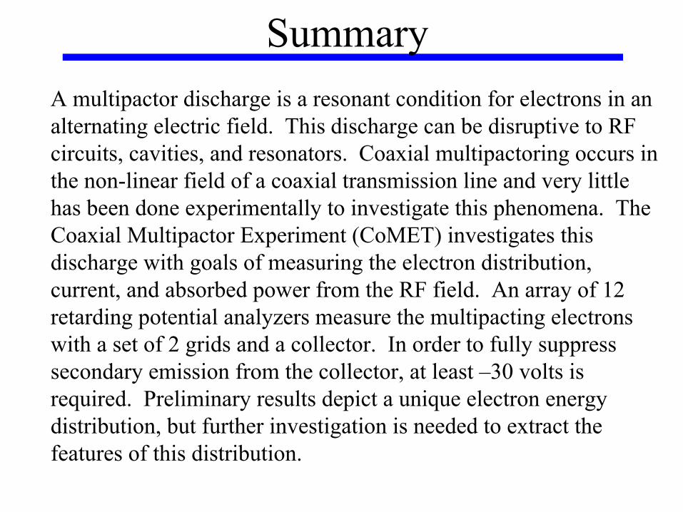
SummaryA multipactor discharge is a resonant condition for electrons in an alternating electric field. This discharge can be disruptive to RF circuits, cavities, and resonators. Coaxial multipactoring occurs in the non-linear field of a coaxial transmission line and very little has been done experimentally to investigate this phenomena. TheCoaxial Multipactor Experiment (CoMET) investigates this discharge with goals of measuring the electron distribution, current, and absorbed power from the RF field. An array of 12 retarding potential analyzers measure the multipacting electrons with a set of 2 grids and a collector. In order to fully suppress secondary emission from the collector, at least –30 volts is required. Preliminary results depict a unique electron energy distribution, but further investigation is needed to extract thefeatures of this distribution.

Outline• Multipactor Basics
– Simple multipactor description– Multipactor discharge properties– Coaxial multipactor description
• CoMET (Coaxial Multipactor Experiment)– Motivation behind experiment– CoMET Experimental Setup– Experimental Results– How this could apply to Fusion/Space systems
• Conclusions and Future Plans

Overview and Motivation
E1
0
e-
SecondaryElectronsSecondaryElectrons
SecondaryElectrons
E2E3
E field wave
T(0 to π) T(π to 2π ) T(2π to 3π)
Emin
Emax

• A multipactor discharge is a resonant condition for electrons in an alternating E field (ref. 1)
• Radio Frequency effect – MHz to 10’s GHz frequencies• Observed in:
– Accelerators– Microwave devices and resonators– RF satellite payloads
• Vacuum conditions required • Electron multiplication from secondary electrons
– Need secondary electron coefficient (SEC) > 1 and sufficient impact energy
– Copper SEC δ = 1.3, Energy = 600eV (peak), 200eV (min)• (Handbook of Chemistry and Physics, 72nd Edition)
Multipactor Basics

• Typically, once the multipactor is fully developed, it is impossible to push thru to higher voltage
• Multipactor current detunes the circuit, dropping the Q factor
•System geometry and E field structure determine the electron motion
•Scaling law -> V α (freq . dist)2 for parallel plate and coaxial geometries

Coaxial Multipactoring
rtEE o
rf)sin( ⋅⋅
=ω
•Not well explored – Most RF transmission lines not in vacuum conditions, only space and fusion groups
•Result of non-linear behavior of electrons
•Single or double surface multipactoring, with sufficient energy for secondary emission
•Simulations show possibility of discharge moving in traveling and mixed wave case (finite VSWR); Also magnetic field complications
Inner diameter
Outer diameter
Time (sec)
Posi
tion
(cm
)

CoMET• Coaxial Multipactor Experiment• Motivation behind experiment
– Alcator C-MOD utilizes high power (MW) RF systems for ICRH (~80MHz)
– Empirically determined E-field breakdown limit, E=15kV/cm, on C-MOD
– Similar limits seen on experiments such as JET and NSTX• Built High Q resonator to build up high power in order to study
high voltage breakdown• Found much lower voltage limit due to coaxial multipactoring in
vacuum region• CoMET Main Goals: Experimentally determine energy, current
density, energy and spatial distributions of coaxial electron multipactor discharges for a range of pressures, frequencies, and wave structures
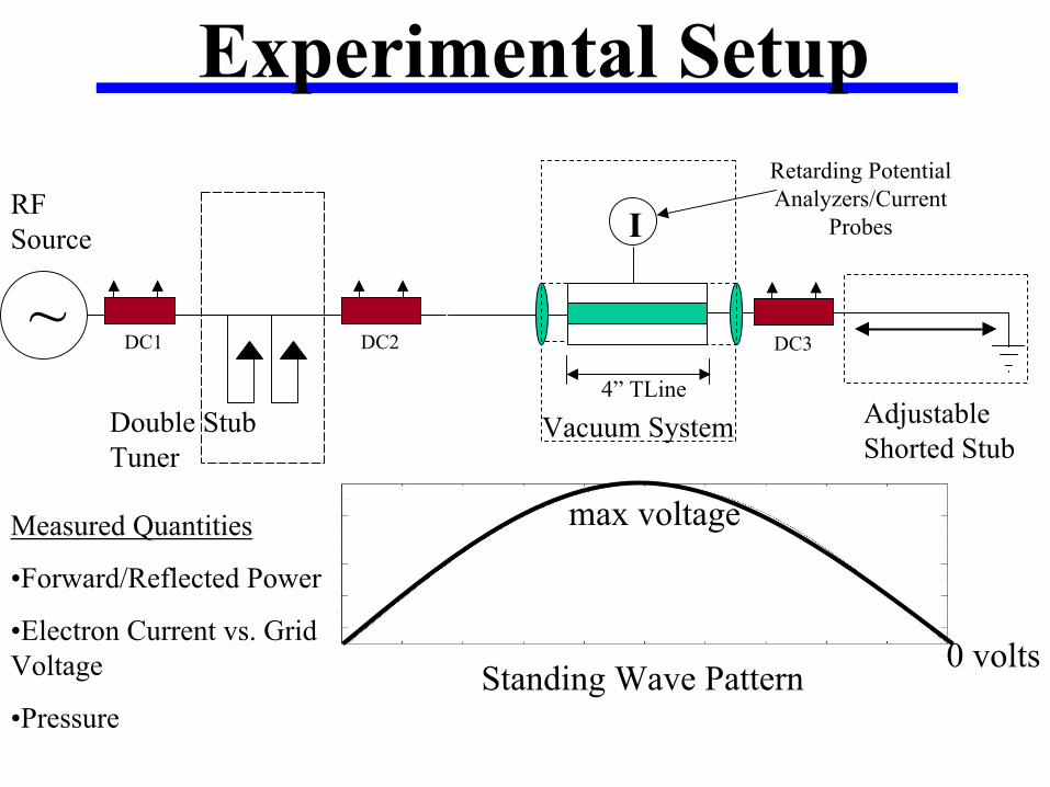
~
RF Source
DC1 DC2
Double StubTuner
I
Retarding Potential Analyzers/Current
Probes
4” TLine
Vacuum System Adjustable Shorted Stub
Standing Wave Pattern0 volts
max voltageMeasured Quantities
•Forward/Reflected Power
•Electron Current vs. Grid Voltage
•Pressure
DC3
Experimental Setup

Adjustable Shorted Stub
DC2
DC3
Tuning Network
Vacuum Chamber

24 Channel High Voltage Bias and Multipactor Current
Amplifier Crate

RPA Array inside vacuum


e-
Entra
nce
Grid
Supr
esso
r Grid
Col
lect
or
Experimental Results
Secondary Suppressed
Suppress Voltage

• Multipactor begins at precise voltage, current increases with input power
• No addition of circulating power once multipactor is established
• Rf circuit is detuned, proportional to multipactor current
• Amount of power absorbed by the discharge is measured by directional coupler difference

Spatial Distribution of Discharge• No bias voltage on
collector, -30 V supression voltage on grid
• Figure depicts small azimuthal variation for multipactor absorption ranging from 0 to 15 W

RPA I-V Characteristic

• Due to drift in electronic signal, baseline signal not zero
• I-V characteristics can be taken relative to baseline
• Fit baseline with quadratic polynomial and subtract to give real characteristic data
• Fit corrected characteristic and take derivative to extract electron distribution functions
• For circulating power of 178 W (133 V) and 5 W of multipactorabsorbed power, Electron distribution functions quadratic shape, with energy (eV) up to peak RF voltage (135 V)
Electron Distribution Functions

Application to Fusion Systems• Use of vacuum coaxial transmission lines• Alcator C-MOD ICRH system has sections of 4 inch
vacuum coaxial lines (as well as poor operation on J antenna)
• ITER plans to have very long, low voltage coaxial transmission lines for ICRH system
• Situation in plasma non-vacuum operation – transmission of power – Finite VSWR– Can the voltage get low enough and the phasing be just right to
initiate a multipactor in the proper region? • Compare time constant for voltage on transmission line
and time constant for multipactor – How long does voltage stay within the multipactor limits?

• Multipactor time ~ 100-200 cycles (ref. 2)
• RF voltage time ~ 10Q/ω– Q=1000, t=1600 cycles– Q=100, t=160 cycles
• If RF voltage moves thru susceptibility region faster than time to steady state multipactor, breakthru can occur
• In this case, a partial multipactor would occur, creating many free electrons which could seed a high voltage arc
Vmax
Vmin
time (Ref. 2)
Breakthru/Partial Multipactor
Multipactor
RF voltage

Conclusions• Multipactor discharges are resonant electron discharges which
effect many different RF systems• Typical scaling is V ~ (f d)2 and can occur in many different
geometries including coaxial transmission line• CoMET has been successful in creating a measurable multipactor
discharge• Up to 10 Watts of power can be absorbed in the multipactor
discharge before reflection coefficient = 0.5• Azimuthal distribution of multipacting electrons mostly even
around coaxial line• Non-monoenergetic, broad energy distribution spread up to peak
RF voltage – Multiple harmonics in electron motion?

Future Plans• Refine RPA electronics for low current measurement to
eliminate zero current signal• Determine spatial variation of multipactor energy distribution• Determine if discharge is single surface or two surface (ID or
OD or both)• Pressure dependence on electron distribution• Verify with parallel plate geometry exp.• Frequency dependence, Finite VSWR (loaded system), different
conductor materials, and DC offset experiments• Understanding coaxial multipactoring good for both Alcator and
science community – Better prevention techniques quenching partial multipactoring that can
seed high voltage arcing– Technology benefit – Electron or radiation source

References1. R.A. Kishek, Y.Y. Lau, et. al. Phys. Plasmas 5 (5), May 19982. R. Kishek, Y.Y. Lau., D. Chernin. Phys. Plasmas 4 (3), March 19973. Woo, Richard. J. Appl. Phys. 39 (3), 1968