Embed Size (px)
Citation preview
BASF Corporation
JOINING OF NYLON BASED PLASTIC COMPONENTS --
VIBRATION AND HOT PLATE WELDING TECHNOLOGIES
Abstract
Previously we reported to SPE’96 the optimized mechanical performance of linear vibration welded nylon 6 and 66 butt joints. Under the optimized vibration welding conditions (amplitude, pressure, meltdown, thickness of interface), the tensile strength at the nylon butt joints was equal to or 14% higher than the tensile strength of the base polymer (matrix).
H. Potente and A. Brubel presented to SPE’94 and SPE’98 an analysis of the welding performance in a family of amorphous and semi-crystalline thermoplastics including nylon 6 using hot-plate welding technologies. For hot-plate welded nylon 6 with a range of glass-fiber reinforcement from 0 to 40% (by weight), the tensile strength at the weld was 40–60% less compared to the tensile strength of the base polymer.
We performed a comparative study of mechanical performance of welded nylon’s butt joints. In this study we analyzed the efficiency of both widely used joining technologies: vibration welding and hot plate welding. Under the optimized hot plate welding conditions, tensile strength of both nylon 6 and 66 joints is close to or slightly higher than the tensile strength of the base polymers.
Presented results will help plastic parts
designers, material developers and manufacturers, by giving them alternatives when choosing types of nylon (6, 66, 66/6, 46, etc.) and welding technologies for a wide range of applications.
Introduction
Nylons (polyamides) are high
performance semi-crystalline thermoplastics with a number of attractive chemical, physical and
mechanical properties. Molded nylon parts are more resistant to creep, fatigue, repeated impact, and so on compared to the parts made of many less rigid thermoplastics.
There are more than a dozen classes of
nylon resins, including nylon 6, nylon 66, nylon 46, nylon 12, etc.). Welded nylons are used in many industrial products, the largest being the automotive. In recent years, demands to use non-filled, fiber-glass reinforced and filled nylon products to replace metals and thermosets in power tools, lawn / garden equipment (leaf blowers, chain-saws, gas-tanks), and the automotive (air induction, power train systems, fluids reservoirs, and other uses), have increased (1, 2).
On average a car uses 18 kg of nylon based plastics. With the annual vehicle production at nearly 15 million, the needed amount of nylons is more than 200 million kilograms -- more than 45 million kilograms for under-the-hood applications alone, and another 11 million kilograms for welded air intake manifolds (AIM) and resonators. The design of these critically stressed welded components requires advanced analysis of structure, noise vibration & harshness (NVH), and welded joints using short-term and long-term strength and life criteria. Reinforced nylon plastics (with 30-35% of glass-fiber by weight) are typically used in design of AIM’s.
The AIMs, resonators, fluid reservoirs, and many others are hollow parts that may be produced by either “lost core”, plastic welding, or welding plus fastening / overmolding technologies. Worldwide (1), nearly 80% of AIMs are produced by either a lost-core injection (46%) molding process or injection molding followed by linear vibration welding (32%). The lost core process is more capital intensive compared to plastics welding processes because it involves additional forming, melting and
metallic core removing. It is also possible (3) to use the hot plate (H-P) welding technology for plastic AIM’s.
Linear vibration welding (LVW) and H-P welding equipment and welding tools and nests are not very expensive, and the welding process itself is not that time consuming. The LVW and H-P welding processes are PC controlled with sensors scanning the positions and automatic reporting the key process parameters critical for both welding technologies.
Similarities and Differences of Linear Vibration (LVW) and Hot-Plate (H-P)
Welding Technologies Different welding methods were used
for joining and assembling hollow plastic parts, such as ultrasonic (U/S), linear vibration LVW), orbital (OVW), spin, extrusion, hot plate / tool (H-P), implant resistance, infrared (IR), etc. LVW and H-P welding methods were utilized in assembling various plastic components made from two, three, or more pieces, molded, extruded, thermally formed from the similar or dissimilar thermoplastics. These joining technologies all share the following typically welding phases: • joined plastic parts placement / nesting and
gripping in specially designed tools; • materials heated in areas where the joints are
to be formed; • local melting in jointed surfaces areas; • surfaces contacting / pressing together for
joining; • cooling in the joint interface and other areas; • welded part removal from welding tool /
nest and machine.
The type of heat generation and heat transfer distinguishes these technologies. The H-P welding method presents an external heating process. The LVW is an alternative internal heating process using friction. For H-P welding technology, the joined surfaces of thermoplastic parts are plasticized or melted prior to welding. It permits direct control of the pre-heating and welding temperature during the heating and fusion phases. For LVW, the temperature in the interface is a function of processing parameters such as time, clamp-pressure, amplitude, frequency, and meltdown, and it depends also on the physical characteristics of the polymers.
Welding temperature in interface during the LVW process is not directly controlled and guided parameter in the standard LVW equipment available from leading manufacturers of welding machines (Branson Ultrasonics Corporation, Bielomatik, Inc., Forward Technology Industries, Inc., etc.). For optimizing LVW processing conditions (including temperature in interface) we used advanced thermal imaging infrared method and computerized system (4).
Orbital vibration welding (OVW) technology allows motion to be programmed in many ways, and it also provides more freedom in designing the weld areas. OVW avoids some of the hindrances of LVW, which has problem with unsupported walls perpendicular to oscillation / vibration direction. The OVW method is also based on friction, which uses an electromagnetic drive to create relative motion between two plastic components. The orbital motion ensures that each point surface of the driven plastic part orbits a different point on the butt joint surface of the stationary part. This orbit of motion is continuous and identical for all points on the joint surface. OVW operates at low vibration amplitudes. Even the sensitive electronic components are not damaged mechanically or thermally, contrary to other plastic joining methods.
The following key processing and weld interface parameters are important for the performance of H-P welded butt joints: • temperature at the heating element / plate; in
local areas of materials or interface at joining; in material(s) diffusion phase; start and final temperatures at hold / sealing (local cooling) phase;
• time: pre-melt, during melting, and during hold / sealing (cooling);
• clamp pressure (variable in process): pre-melt and during hold / sealing (cooling);
• thickness of interface / distance: of pre-heated layer(s); melt collapse (at joint sealing phase); final thickness of the interface (in local areas).
For H-P welding, it is critically important to achieve a sufficient and consistent through-thickness and local material heating during the pre-melt phase. For the semi-crystalline materials the requirements are (5):
• melt layer thickness (meltdown) of about 30% of the wall thickness (for a wall thickness < 4 mm);
• sealing distance / joining displacement of approximately 60 to 80% of above mentioned melt thickness;
• hot-plate / tool temperature (for semi-crystalline plastics application) should be equal to the melting peak, + 70°C.
The H-P welding technology is a
reliable joining method for injection molded, blow molded, and extruded hollow components. Typically, H-P welding machines have all the advantages of horizontal or vertical design (see Figure 1). These include welds of small and big components (i.e. gas tanks), long / large diameter gas pipes made from the similar plastics.
When applying the H-P welding method, we need to be aware of the following disadvantages: • design limitations: plane configuration of
the joint surfaces; position tolerance (centering capability for non-stiff applications – flexible walls, etc.);
• dimensional limitations (in non-isometric melt distribution in local areas of possible gaps) in reinforced plastics that are dimensionally unstable, and for non-optimized molding conditions;
• limitations on optimizing clamp-force / pressure (in case of welding of the small components).
For the high performance LVW and
OVW joints the following, processing and weld interface parameters are critical: • temperature: in local and weld interface
areas during the melt formation phase; at start and final temperatures at hold / sealing (local cooling) phase;
• time: pre-melt (heating), melting, hold / sealing (cooling);
• clamp pressure (variable in process): pre-melt; hold / sealing (cooling);
• welding amplitude (variable in process): pre-melt (heating), melting;
• thickness of interface: of pre-heated layer(s); melt collapse / melt-down; final thickness of interface (in local areas);
• direction of oscillation / linear vibrations (longitudinal, perpendicular to thickness of wall / bead, by angle);
• vibration frequency (typically in range from 120 to 240 Hz).
Typically the LVW machines combine
all the advantages of vertical or horizontal & vertical design for joining of components made from the similar or de-similar plastics. The sizes of the joined parts vary from small (valves, fluid reservoirs, etc.) to very large (cars crossbeams, etc.). When applying LVW and OVW technologies, we need to be aware of the following info: • weight (of the upper fixture + nested part)
and design limitations: in the sizes of the part placed in upper nest / fixture;
• limitations on the weld plane configuration and maximum value of out-of-welded plane angle;
• difficulties (to achieve optimized mechanical strength / life performance of joint) in using dissimilar plastics with the different melt temperatures (of 50°C);
• dimensional limitations (in non-isometric melt distribution in local areas of possible gaps) in reinforced plastics and for non-optimized molding conditions.
For semi-crystalline materials, it is
necessary to reach a melt thickness (meltdown) in the range 0.7-1.5 mm (6-9). The LVW and OVW processes are less sensitive to dimensional tolerances because they both are self-adjusting in the contact areas. It is possible to close a gap up to 5 mm wide, between two joined surfaces with weld clamp pressure.
The LVW technology is a reliable
joining method for injection molded, blow molded and extruded thermoplastics, and hollow components. It is critical to keep the needed stiffness of the walls in welding directions perpendicular to wall thickness and by angle.
Materials and Welded Joint
The thermoplastics used in this
investigation were heat stabilized nylon 6 and nylon 66 (for nylon 66/6, nylon 46 limited data for LVW technology only) pigmented black, typical for automotive under-the-hood components. The materials have the following level of fiber-glass loading / reinforcement (% by weight): • nylon 6 (0; 14; 25; 33; 45, and 50%);
• nylon 66 (0 and 33%); • nylon 66/6 copolymer (30%). • nylon 46 (30%); • high temperature resistance nylon HTN
(35%).
We also evaluated the performance of LVW joints using nylon 6 plastics filled by mineral (40% by weight) and glass/mineral (15% glass fiber, and 25% mineral filled, both by weight).
Melting points T for above evaluated nylons are the following (10): • nylon 6, T = 223°C; • nylon 66, T = 261°C; • nylon 66/6, T = 238°C; • nylon 46, T = 290°C; • nylon HTN, T = 300°C. Welding Equipment and Processing-
Parameters
The LVW and OVW of butt joints were made at Branson Ultrasonics Corporation. A modified MiniWelder-II and CV-12 machines were used for LVW and OVW, respectively. The key LVW parameters were as follows: • Weld Amplitude: 1.02 ~ 1.80 mm • Melt-Down: 0.50 ~ 5.0 mm • Weld Frequency: 210 Hz • Hold / Cooling Time: 2 ~ 10 sec. • Maximum Clamp Force: 3.6 kN • Driven Platen Fixture Weigh: 2 kg
The key OVW parameters were as follows (similar to the above described LVW conditions): • Weld Amplitude: 0.25 ~ 1.50 mm • Melt-Down: 0.50 ~ 2.0 mm • Weld Frequency: 190 Hz • Hold / Cooling Time: 2 ~ 10 sec. • Maximum Clamp Force: 0.5 kN • Driven Platen Fixture Weigh: 2 kg
The H-P welding of butt joints was conducted at Bielomatik Inc. using a specially designed LabWeld vertical machine. The key H-P parameters were as follows: • Maximum Temperature of Hot-Plate /
Heating Element: 380 °C • Maximum Pre-Melt Clamp Force: 3.0 kN • Maximum Pre-melt + Melting Time: 30 sec. • Melt-Down: 0.50 – 5.0 mm
• Maximum Hold / Sealing Time: 15 sec.
For this evaluation (LVW, OVW, and H-P welding technologies) we used the recommended butt joint design, consisting of two beads 4 mm and 6.25 mm thick and welded together the following injection molded rectangle plague: • 100 (or 150) mm × 65 mm × 6.25 mm; • 100 (or 150) mm × 65 mm × 4 mm. Sizes (length × width) of the welded plaques are: 100 (or 150) mm × 125 mm (approximately).
For the evaluation of ultrasonic welding technology we used AWS (American Welding Society) injection molded samples.
Experimental Procedures
Process Optimization – Time-Temperature-Profile
One of the most important parameters affecting the performance of welded joints is the temperature during joining process. An advanced method (4) of non-contact thermal imaging (infrared) was applied in this study to analyze the temperature changes during the welding process.
For the temperature detection in welding process we used Thermovision 900®
Series System (FSI / Agema Infrared). The infrared (IR) camera continuously monitors the temperature distribution in overall and local areas (Figure 3). The computer electronically labels on time gates images according to the duration of time between sending and receiving a pulse. The software then converts these thermal pictures into a series of thermal wave images which might also detect possible material or welding defects at various depth below the surface.
During a welding, heating and melting
of the same thermoplastics proceeds symmetrically. This process will be not the same, when joined components are molded of dissimilar materials. Because of differences in thermal properties, one material may melt at faster rate. Sometimes, one of the materials may not even reach melting point / temperature ant the joint interface.
We measured the time-dependent temperature distribution and melt propagation in
the weld interface (at five local areas with the same size) during the LVW process. The results were obtained at various longitudinal welding conditions (amplitude-pressure-meltdown), at vibration welding frequency =210 Hz for the similar or dissimilar nylon 6 and nylon 66 that were non-filled, filled / reinforced.
Shown in Figures 4 and 5 are time vs. temperature plots for 33% glass-fiber reinforced (by weight) nylon 6 and nylon 66. The 2-second plastic pre-heating phase is too short for the heat to penetrate through all interface areas; an additional 4-6 seconds are needs for this purpose. The distribution of weld temperature in local areas was non- isochronal (uniform in duration); it was dependent on the flatness of welded surfaces, nest design and heat transfer-out of interface by the melted flush.
The temperatures of the melt in interface (for 33% glass-fiber reinforced by weight) at the steady state were in the following ranges: • 270 ~ 285 °C (nylon 6); • 295 ~ 320 °C (nylon 66).
These melt temperatures were not affected by the level of glass-fiber reinforcement from the 0 to 40% (by weight) under optimized (by mechanical performance criteria) LVW conditions. The reinforcement however was changing the heat transfer processes. For nylon 66 plastics, the coefficient of thermal conductivity may double with glass-reinforcement in the range of 0 to 40% (by weight) (10). Similar time-temperature data may also be obtained for the H-P welding technology. When LVW machine is shut off, the weld penetration continues to increase because the clamp pressure causes the molten interface to flow until it solidifies. During the shutting off phase the interface temperature has a tendency to increase (for 40°C on average, see Figures 4 and 5). The maximum temperature of the joint interface was equal to the melting point of welded polymers or blends + (85-90°C). The results in this study are slightly different from the data for the H-P welding technology (5). These differences may reflect the difference in the methods, calibration and measurement procedures.
Local Reinforcement Effects in Weld Interface
In quality control and performance evaluation of the welded components and plaques tensile test and burst test methods were usually used (6-7). The tensile strength of welded joints or specimens is a key parameter for the material selection, component design, joint performance evaluation, and welding optimization. However, at the current time, the standards for defining LVW, OVW, and H-P welding, butt joint strength are not available. At the same time, most of the plastic weld performance data have been obtained by testing the tensile strength of welded butt joints. The tensile test results are very important also for joint design evaluation and improvement, and new materials development for welded parts.
The test data were obtained from rectangle tensile specimens (10 mm width, 125 mm length) cut and machined from welded plaques (150/100 mm × 125 mm). For either LVW, OVW, or H-P welding processing conditions a minimum of five specimens were tested using ISO 527 procedures. In most applications the weld flash / “bead” is not removed. In this study weld flash was machined off prior to a tensile test. The tensile specimen, which has a uniform butt weld at middle length, is then subject to constant displacement / strain rate. The specimen is loaded until it fails. All tensile test results were used for the performance optimization. Samples with high tensile strength were selected to perform the morphology analysis in the weld zone (interface).
Details of the glass-fiber orientation in nylon’s weld interface area were presented in (11). Optical microscopy was used to study the morphology of the samples (fibers-glass orientation, local reinforcement effects, presence of microporosity, small inclusions, etc.), while image analysis was used to quantitatively characterize the fiber-glass state including diameter, length, and breakage, and positioning of the welded components (penetration, melt-down, etc.).
Furthermore, a study of the weld zone fracture surfaces on both technologies by scanning electron microscopy suggested that there is no excessive breakage of glass fiber at the weld interface. This technique allows one to determine quantitatively the effects of local reinforcement on the weld fracture surfaces.
LVW and OVW Technologies
Table 1 summarizes the results of the tensile strength of glass fiber reinforced nylon 6 based plastics and welded butt joints from LVW technology, optimized processing conditions, and longitudinal vibrations (11).
The results may also be compared (see Table 2) with the tensile strength of the base matrix m / polymer (or to the tensile strength of the welded plastic pl), using welding factor fm (or fpl) correspondingly. Welding factors fm and fpl are equal to the following ratios (1 and 2): fm = tensile strength of weld / tensile strength of base polymer (1) fpl = tensile strength of weld / tensile strength of reinforced (or filled plastic) (2) It was reported previously that for glass fiber reinforced thermoplastics, the maximum weld strength for the butt joints is approximately equal or less than the strength of the matrix or base materials (3, 8-9). The reduction in tensile strength was attributed to the changes in the glass fiber orientation at the welded joint (8-9,12), where the glass fibers align along the weld plane, perpendicular to the applied stresses. Figure 6 explains strength reduction effects typical for the non-optimized welding conditions. The orientations of glass fibers are found to be the following: • in the weld interface local area fibers were
oriented mostly along the weld-melt flow direction;
• in the bulk of the material the fiber orientation was random, depending on part design and molding conditions, etc.
The effects of inter-diffusion at
polymer-polymer interface for amorphous and semi-crystalline materials have been reported before (14). The minor chain repetition model explained the effects of non-reinforced plastics healing and strengthening during the welding process time. In this study the effects of strength and performance improvement for welded joints were explained (11) from the dynamic mode of glass fiber re-orientation in joining process time.
For OVW technology it is possible to select among circular (orbital), straight (linear), or elliptical weld paths. The tensile strength of
OVW is slightly higher than that in LVW technology (see Table 3). By nature of heat generation an orbital / circular and elliptical path is more efficient (at the optimized welding parameters) in glass-fibers re-orientation and polymer blending.
With the optimized welding parameters
in LVW and OVW, some of the glass fibers were found to orient perpendicular or at an angle (see Figures 7) to the weld plane across the interface. This local reinforcement effect for LVW and OVW methods were observed for both nylon 6 and nylon 66 plastics. In reference (11) we explained the effects of fiber orientation in dynamic terms of vibration process and thickness of the interface comparable with the length of short glass-fibers. For nylon 66 plastics we achieved the performance of weld similar to that in nylon 6 for LVW and OW techniques. H-P Welding Technology
H-P welding is not a dynamic process in terms of heat generation. It is a very attractive welding method for the evaluation of the reinforcement effects in the weld interface area. In experimenting with H-P welding procedures we used the same plastics. Our experiments were conducted using nylon 6 products with glass-fiber reinforcement in the range of 0 to 45% (by weight) and nylon 66 with 0 and 33 % glass fiber reinforced (by weight).
For H-P welding technology we
repeatedly received localized reinforcement effects in nylon 6 and nylon 66 plastics (see Figure 8). The best tensile strength was achieved for nylon 66 with 33%-glass-fiber reinforcement by weight (Table 4).
The results on the efficiency (by mechanical performance criteria) of the LVW, OVW, H-P, and ultrasonic (U/SW) (16) welding methods for 33% glass fiber reinforced (by weight) nylon 6 plastics are presented in Table 5.
Weldability of Dissimilar Plastics (LVW Technology)
For automotive and appliances, welding of dissimilar (by composition: type of matrix, fillers, reinforcements, additives, etc.) plastics, copolymers, and blends (nylon 66 with nylon 6) is needed but only a limited literature is available
in this area. Comprehensive results concerning the strength and bonding in linear vibration welded polycarbonate to polyetherimide butt joints were presented in (15). Currently there is no published data available on the performance of weld dissimilar nylon (nylon 6, nylon 66, nylon 610, nylon 46, nylon 12, etc.) based plastics. For design with nylon it is important to obtain data for the weld strength between the following dissimilar materials: • nylon 6 welded with nylon 66; • nylon 66/6 copolymer welded with nylon 6 /
or nylon 66; • nylon 66 or nylon 6 welded with high
temperature resistance nylon (HTN); • nylon 46 welded with nylon 6 / or nylon 66.
Table 6 summarizes the results of the tensile strength of the similar butt joint when the same classes of nylon based plastics were welded together
It was pointed out (14) that only a
limited inter-diffusion is expected at the joint of dissimilar polymers. Because of their difference in thermal properties, one material may melt faster than the other. Sometimes, one of the materials may not even reach its melting point at the interface. In all of the welds between two plagues or specimens, greater flash was seen in the nylon 6 side. This phenomenon is consistent with the lower melting temperature in these nylon materials. Due to the temperature gradient in the width of the joint and the length of the weld, the lateral flow of the joined plastics is not uniform (15). Additional experimental data is needed for optimizing the dissimilar nylon butt joint (Table 7).
The low tensile strength in the joints between nylon 66 / nylon 6 with nylon 46 or HTN has been related to the polymers mixing and weld interface thickness. At the steady state welding process, the nylon 66 or nylon 6 and thickness becomes constant, but the band thickness of HTN continues to rise. For the dissimilar welds the final thickness of the interface is smaller than that of the similar welds (at optimized conditions). In (11) we showed positive influence of the interface thickness on the weld performance. To increase the mechanical performance of the dissimilar joints we need to achieve asymmetric heating conditions for the two halves of the joined parts. This however is not possible in the LVW or OVW methods due to the nature of the internal
heating (self-adjustable process). For the H-P welding technology we need to design special heating equipment with two separate heating elements, adjustable according to the thermal properties of the materials at the joint.
Concluding Remarks Morphology studies using microscopy have revealed the fiberglass distribution and orientation in the bulk of the material and at the interface. Under the optimized LVW and H-P welding conditions, part of the glass fibers were found to orient perpendicular or at an angle to the weld plane, and they were also found to be crossing the interface.
These local reinforcement effects were found to be very repeatable for the butt joint welded from similar (both halves are nylon 6 or nylon 66, and nylon 66/6 copolymer) and dissimilar (nylon 66 with nylon 6) plastics. At present the optimized weld performance for HTN dissimilar butt joints is not yet achieved due to the large difference in the melt temperature and solubility of the base materials.
Comparing studies of LVW and OVW
joining technologies demonstrated that the OVW process is very efficient for nylons and may be used as an alternative to LVW and ultrasonic technologies for welding of the small components.
For both LVW and H-P welding
technologies the maximum tensile strength at weld was achieved in materials with 14 to 24% glass fiber reinforcement (by weight).
Studies on heat-generation and melt propagation in LVW processing using infrared technology have demonstrated the dynamic of temperature distribution in overall and interface areas. For joining of the similar nylons, a difference of 15 – 20 °C at the interface was found during the steady state in LVW technology and as a result the hot-plate / tool temperature (H-P welding technology) is recommended. The difference may be due to the accuracy of the previously applied measurement methods, the calibration procedures, and so on. The utilization of the standard IR method and Thermovision 900® Series System (FSI / Agema) allows one to monitor the temperature distribution in overall and local (interface) areas.
The presented optimized weld mechanical performance data will allow designers to recommend LVW / OVW or H-P
welding technologies in plastic product development for welding applications and welded components manufacturing.
Acknowledgements
Support provided by Branson
Ultrasonics Corporation, Bielomatik Inc. and FSI / AGEMA Infrared Systems is gratefully acknowledged. The author wishes to thank Steve Preziosi for testing, Caroline Bednarczyk for the microscopy data, and Chris Roth and Nanying Jia for help in preparing this study for publishing. Their contributions are greatly appreciated.
References 1. “Plastics Continue to Penetrate Automotive
Air Induction Systems”, SME, Injection Molding, September 1998, pp. 37-38.
2. E. Carlson, K. Nelson, “Nylon Under-the-Hood. A History of Innovation ”, SPE, Automotive Engineering, December 1996, pp. 84-89.
3. Mark M. Mastic, “Multishell Technology for Plastic-Part Manufacture”, Processing of Structural Plastics’95, Technical Conference and New Product Design Competition”, SPI, April 1995, pp. 1-5.
4. “Seek But Don’t Destroy”, Machine Design, March 1996, pp. 60-63.
5. H. Potente, A. Brubel, “Welding Behaviour of Filled and Reinforced Thermoplastics with Hot-Plate Welding”, ANTEC’98, SPE Conference Proceedings, Vol. 1,pp. 1062-1066.
6. V. Kagan, Vibration Welding of Glass-Fibre-Reinforced Polyamide Plastics, Kunststoffe plastic europe, Vol 87, December 1997, pp. 1804-1807.
7. Chul S. Lee, Val Kagan, Norman Knowlden, etc., “Optimization of Vibration Weld Joint Strength for Plastic Air Intake Manifold”, SAE’98 Technical Paper Series - Plastics: Components, Processes, and Technology (SP-1340), pp. 111-115.
8. Ian D. Froment, “Vibration Welding Nylon 6 and Nylon 66 – A Comparative Study”, ANTEC’95, SPE Conference Proceedings, Vol. 1,pp. 1285-1289.
9. H. Potente, M. Uebbing and E. Lewandowski, “The Vibration Welding of Polyamide 66”, Journal of Thermoplastic
Composite Materials, Vol. 6, January 1993, pp.2-17.
10. Melvin I. Kohan, “Nylon Plastics Handbook”, Hanser Publisher, New York, 1995, 631 p.
11. V. Kagan, Siu-Ching Lui, etc., “The Optimized Performance of Linear Vibration Welded Nylon 6 and Nylon 66 Butt Joints”, ANTEC’96, SPE Conference Proceedings, Vol. 1,pp. 1266-1274.
12. K.W. Nelson, “Vibration Welding: A Low Cost Assembly Process for Thermoplastic Intake Manifolds”, SAE’95 Technical Paper Series - Plastics: Components, Processes, and Technology (SP-950230), 10 p.
13. Ian D. Froment, “Central Composite Design – An Aid to Weld Optimization”, ANTEC’98, SPE Conference Proceedings, Vol. 1, pp. 1055-1059.
14. Richard P. Wool, Polymers Interfaces – Structure and Strength. Hanser Publishers, New York, 1995, 494 p.
15. V. K. Stokes and S. Y. Hobbs, “Strength and Bonding Mechanisms in Vibration-Polycarbonate to Polyetherimide Joints”, Polymer Engineering and Science, Mid-December, 1989, Vol. 29, No. 23.
16. D. A. Grewel, “Amplitude and Force Profiling: Studies in Ultrasonic Welding of Thermoplastics”, ANTEC’96, SPE Conference Proceedings, Vol. 1, pp. 1051-1058.
Key Words
Nylon, polyamide, welding, joining, linear
vibration, hot plate, test, evaluation, interface, morphology, thermal image, fiber-glass reinforcement, butt joint.
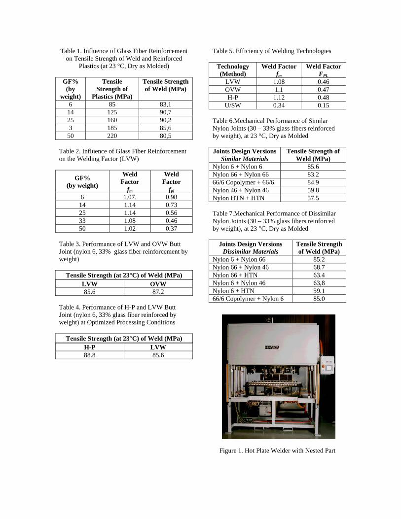
Table 1. Influence of Glass Fiber Reinforcement on Tensile Strength of Weld and Reinforced
Plastics (at 23 °C, Dry as Molded)
GF% (by
weight)
Tensile Strength of
Plastics (MPa)
Tensile Strength of Weld (MPa)
6 85 83,1 14 125 90,7 25 160 90,2 3 185 85,6
50 220 80,5 Table 2. Influence of Glass Fiber Reinforcement on the Welding Factor (LVW)
GF% (by weight)
Weld Factor
fm
Weld Factor
fpl6 1.07. 0.98
14 1.14 0.73 25 1.14 0.56 33 1.08 0.46 50 1.02 0.37
Table 3. Performance of LVW and OVW Butt Joint (nylon 6, 33% glass fiber reinforcement by weight)
Tensile Strength (at 23°C) of Weld (MPa) LVW OVW 85.6 87.2
Table 4. Performance of H-P and LVW Butt Joint (nylon 6, 33% glass fiber reinforced by weight) at Optimized Processing Conditions
Tensile Strength (at 23°C) of Weld (MPa) H-P LVW 88.8 85.6
Table 5. Efficiency of Welding Technologies
Technology (Method)
Weld Factor fm
Weld Factor FPL
LVW 1.08 0.46 OVW 1.1 0.47 H-P 1.12 0.48
U/SW 0.34 0.15
Table 6.Mechanical Performance of Similar Nylon Joints (30 – 33% glass fibers reinforced by weight), at 23 °C, Dry as Molded Joints Design Versions
Similar Materials Tensile Strength of
Weld (MPa) Nylon 6 + Nylon 6 85.6 Nylon 66 + Nylon 66 83.2 66/6 Copolymer + 66/6 84.9 Nylon 46 + Nylon 46 59.8 Nylon HTN + HTN 57.5 Table 7.Mechanical Performance of Dissimilar Nylon Joints (30 – 33% glass fibers reinforced by weight), at 23 °C, Dry as Molded
Joints Design Versions
Dissimilar Materials Tensile Strength of Weld (MPa)
Nylon 6 + Nylon 66 85.2 Nylon 66 + Nylon 46 68.7 Nylon 66 + HTN 63.4 Nylon 6 + Nylon 46 63,8 Nylon 6 + HTN 59.1 66/6 Copolymer + Nylon 6 85.0
Figure 1. Hot Plate Welder with Nested Part
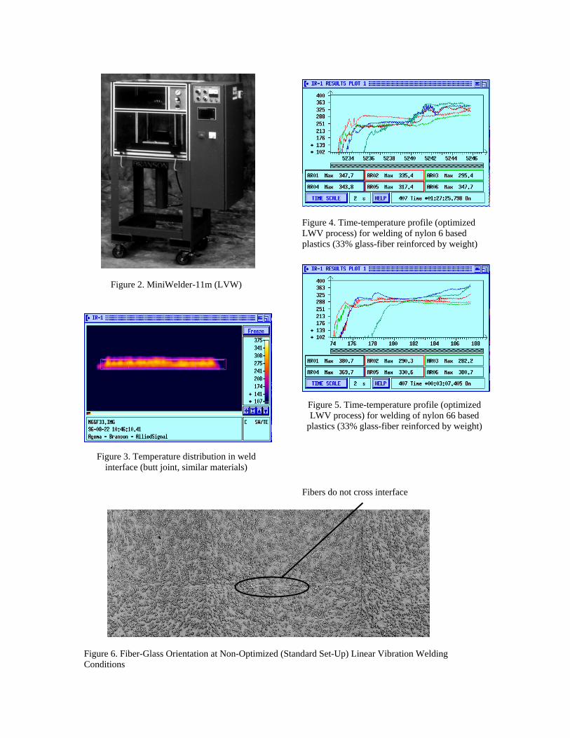
Figure 2. MiniWelder-11m (LVW)
Figure 3. Temperature distribution in weld interface (butt joint, similar materials)
Figure 4. Time-temperature profile (optimized LWV process) for welding of nylon 6 based plastics (33% glass-fiber reinforced by weight)
Figure 5. Time-temperature profile (optimized LWV process) for welding of nylon 66 based
plastics (33% glass-fiber reinforced by weight)
Fibers do not cross interface
Figure 6. Fiber-Glass Orientation at Non-Optimized (Standard Set-Up) Linear Vibration Welding Conditions
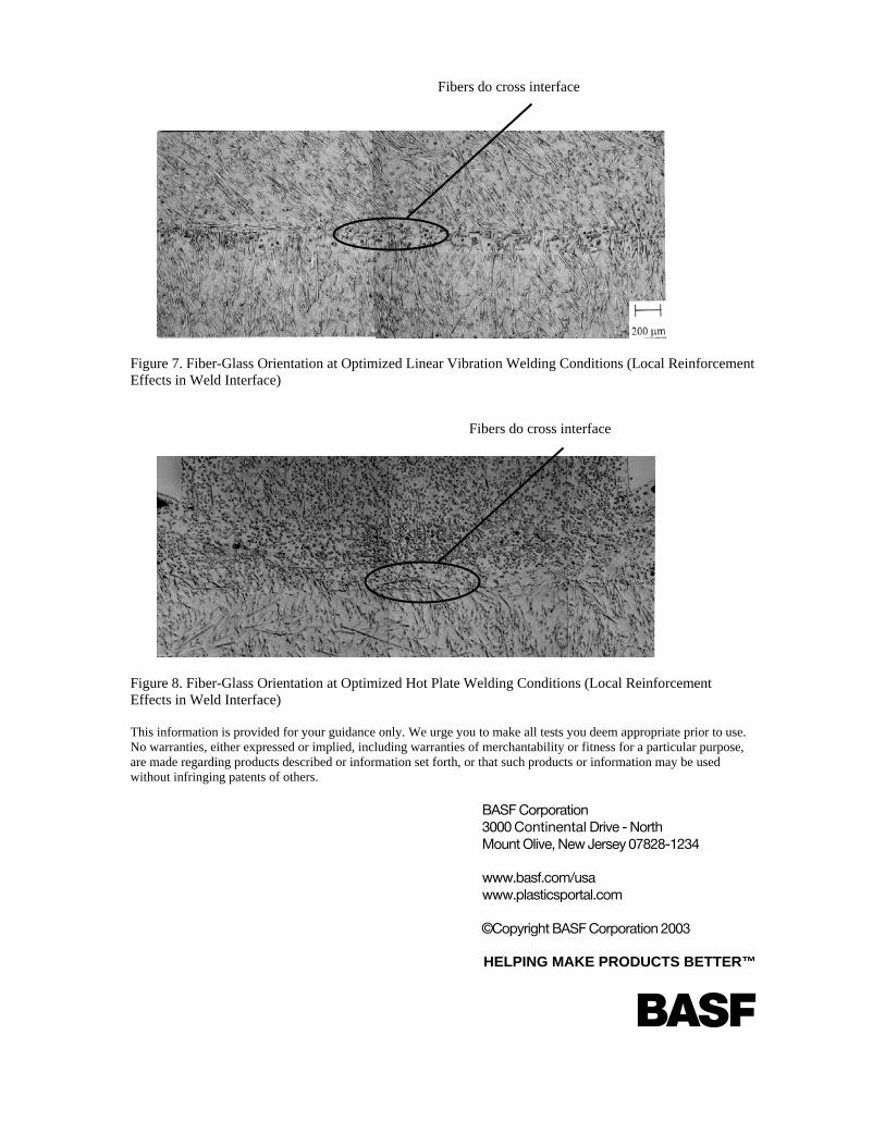
Fibers do cross interface
Figure 7. Fiber-Glass Orientation at Optimized Linear Vibration Welding Conditions (Local Reinforcement Effects in Weld Interface)
Fibers do cross interface
Figure 8. Fiber-Glass Orientation at Optimized Hot Plate Welding Conditions (Local Reinforcement Effects in Weld Interface)
This information is provided for your guidance only. We urge you to make all tests you deem appropriate prior to use. No warranties, either expressed or implied, including warranties of merchantability or fitness for a particular purpose, are made regarding products described or information set forth, or that such products or information may be used without infringing patents of others.
BASF Corporation 3000 Continental Drive - North Mount Olive, New Jersey 07828-1234 www.basf.com/usa www.plasticsportal.com ©Copyright BASF Corporation 2003
HELPING MAKE PRODUCTS BETTER™