Embed Size (px)
Citation preview
John Pulsifer, Mark TillackS. S. Harilal, Joel
Hollingsworth
GIMM experimental setup and tests at prototypical pulse
length
HAPL Project MeetingPrinceton, NJ
11-12 December 2006
With contributions from: Roman Salij (Cabot Microelectronics; Engineered
Surface Finishes)
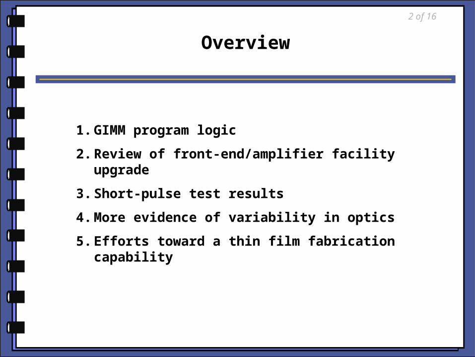
1. GIMM program logic
2. Review of front-end/amplifier facility upgrade
3. Short-pulse test results
4. More evidence of variability in optics
5. Efforts toward a thin film fabrication capability
Overview
2 of 16
3 of 16
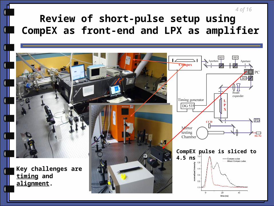
Review of short-pulse setup using CompEX as front-end and LPX as amplifier
Key challenges are timing and alignment.
CompEX pulse is sliced to 4.5 ns
4 of 16
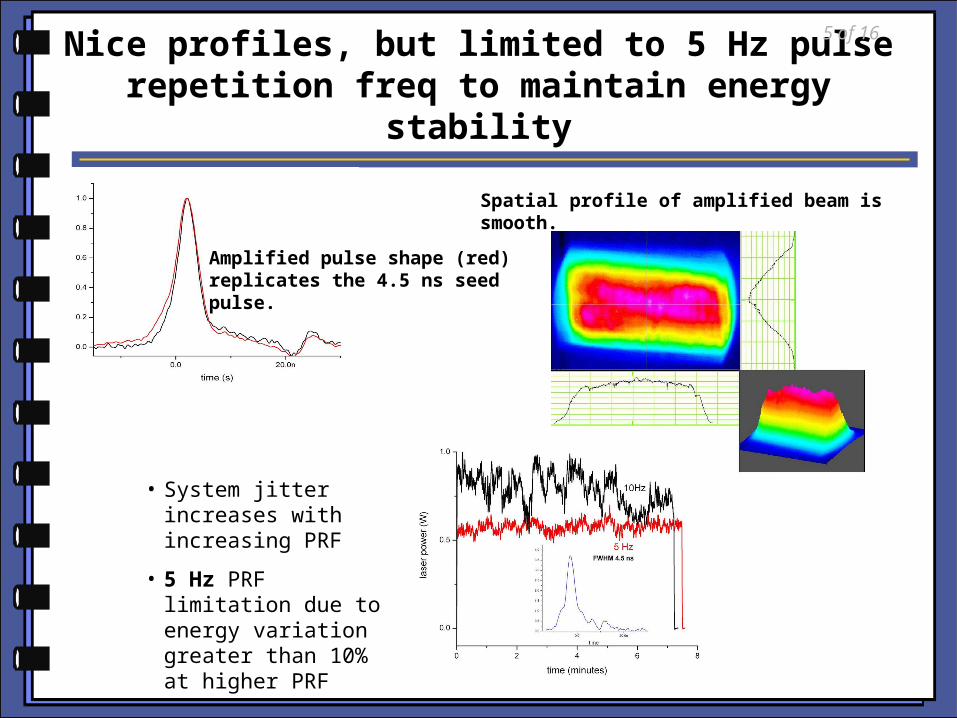
Nice profiles, but limited to 5 Hz pulse repetition freq to maintain energy stability
• System jitter increases with increasing PRF
• 5 Hz PRF limitation due to energy variation greater than 10% at higher PRF
Amplified pulse shape (red) replicates the 4.5 ns seed pulse.
Spatial profile of amplified beam is smooth.
5 of 16
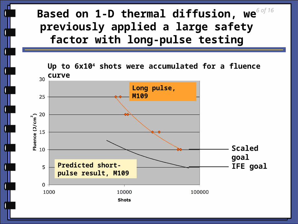
Based on 1-D thermal diffusion, we previously applied a large safety
factor with long-pulse testing
Long pulse, M109
Predicted short-pulse result, M109
IFE goal
Scaled goal
Up to 6x10⁴ shots were accumulated for a fluence curve
6 of 16
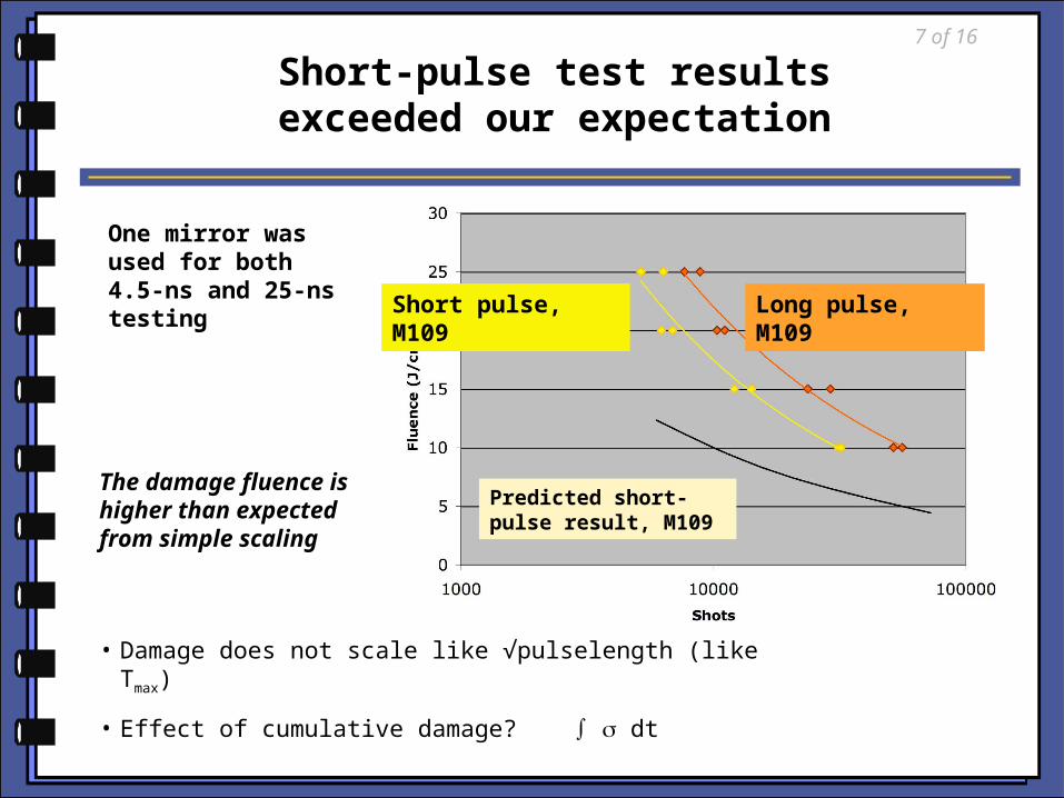
Long pulse, M109
Short pulse, M109
Predicted short-pulse result, M109
Short-pulse test results exceeded our expectation
The damage fluence is higher than expected from simple scaling
One mirror was used for both 4.5-ns and 25-ns testing
• Damage does not scale like √pulselength (like Tmax)
• Effect of cumulative damage? ∫ dt
7 of 16
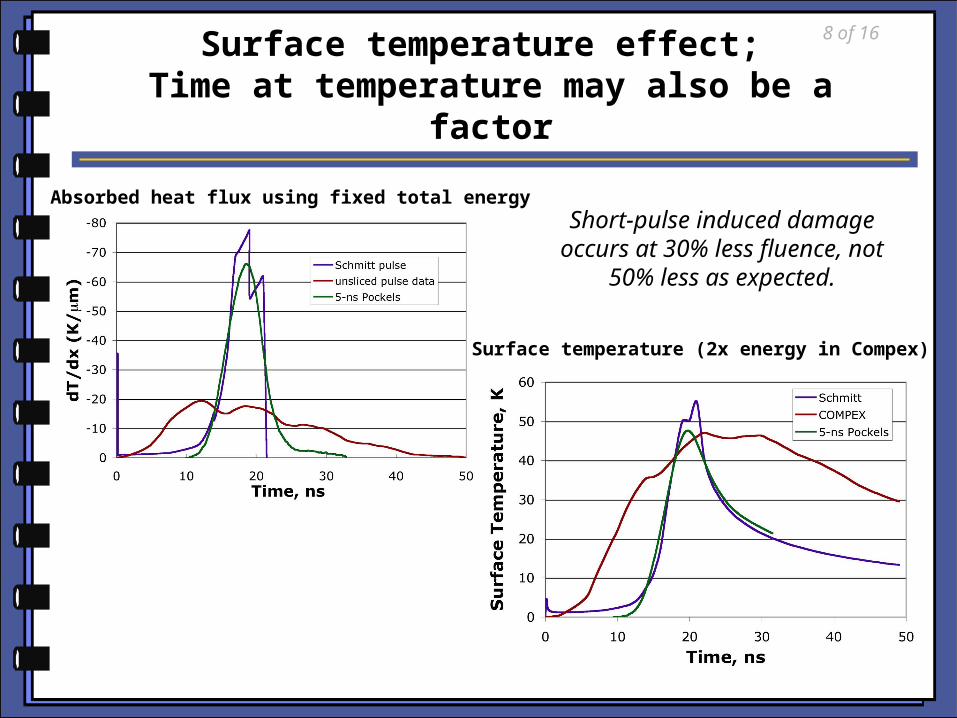
Surface temperature effect; Time at temperature may also be a factor
Absorbed heat flux using fixed total energy
Surface temperature (2x energy in Compex)
Short-pulse induced damage occurs at 30% less
fluence, not 50% less as expected.
8 of 16
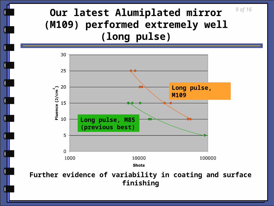
Our latest Alumiplated mirror (M109) performed extremely well
(long pulse)
Further evidence of variability in coating and surface finishing
Long pulse, M109
Long pulse, M85 (previous best)
9 of 16
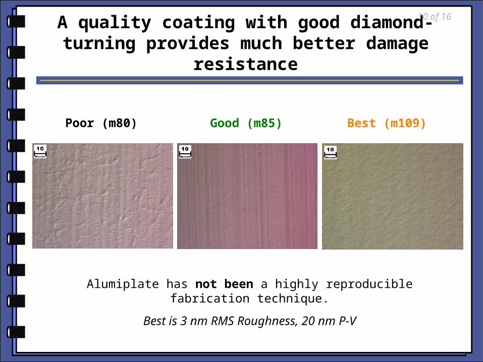
A quality coating with good diamond-turning provides much better damage
resistance
Alumiplate has not been a highly reproducible fabrication technique.
Best is 3 nm RMS Roughness, 20 nm P-V
Poor (m80) Good (m85) Best (m109)
10 of 16
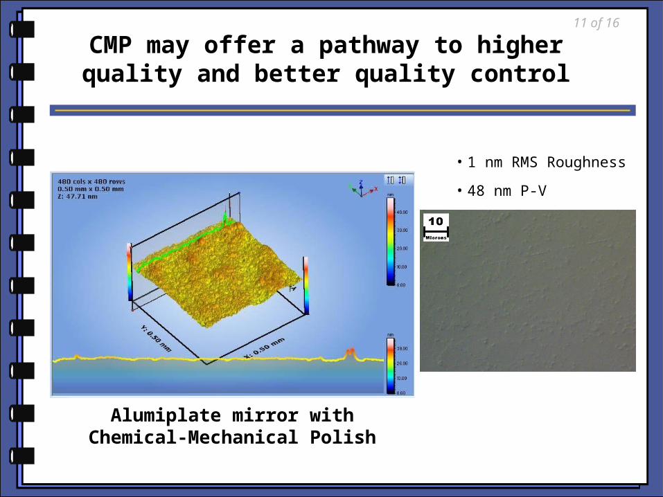
CMP may offer a pathway to higher quality and better quality control
• 1 nm RMS Roughness
• 48 nm P-V
Alumiplate mirror with Chemical-Mechanical Polish
11 of 16
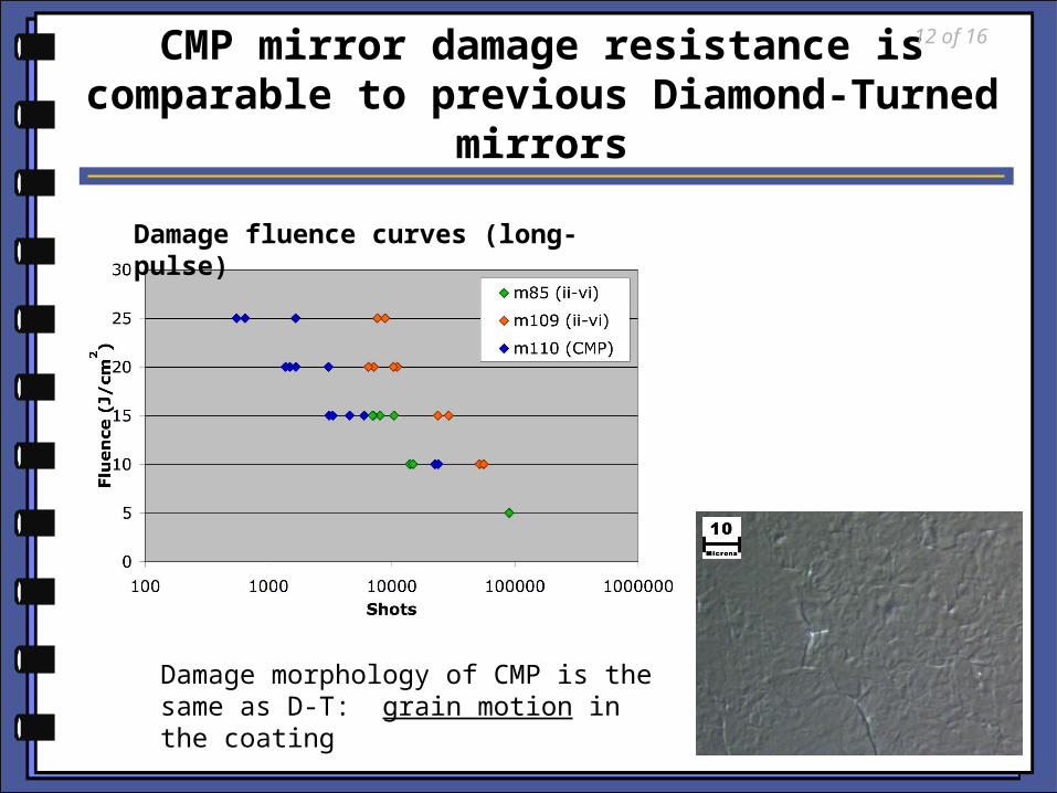
CMP mirror damage resistance is comparable to previous Diamond-
Turned mirrors
Damage morphology of CMP is the same as D-T: grain motion in the coating
Damage fluence curves (long-pulse)
12 of 16
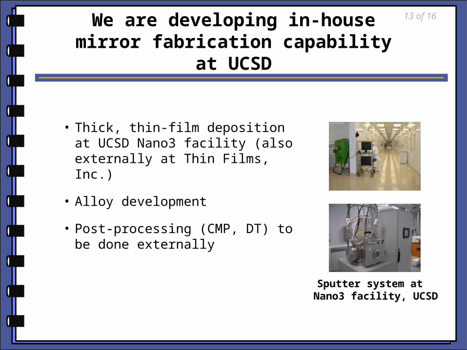
We are developing in-house mirror fabrication capability at
UCSD
• Thick, thin-film deposition at UCSD Nano3 facility (also externally at Thin Films, Inc.)
• Alloy development
• Post-processing (CMP, DT) to be done externally
Sputter system at Nano3 facility, UCSD
13 of 16
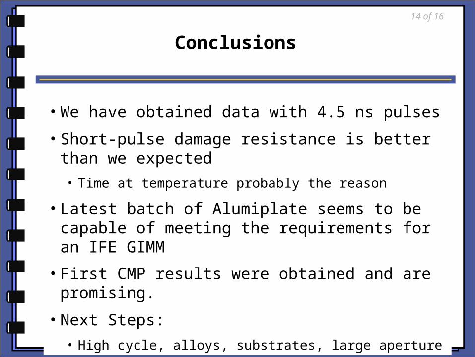
Conclusions
• We have obtained data with 4.5 ns pulses
• Short-pulse damage resistance is better than we expected
• Time at temperature probably the reason
• Latest batch of Alumiplate seems to be capable of meeting the requirements for an IFE GIMM
• First CMP results were obtained and are promising.
• Next Steps:
• High cycle, alloys, substrates, large aperture
14 of 16
Next-step goals for GIMM R&D15 of 16

16 of 16
Questions?