Embed Size (px)
Citation preview

HAPLHAPL
Concepts and Requirements for GIMM
Structures
Concepts and Requirements for GIMM
Structures Thomas Kozub, Charles Gentile, Irving Zatz -
PPPLMohamed Sawan - FTI UW
John Pulsifer, Mark Tillack - UCSDMalcolm McGeoch - PLEX
Tom Lehecka - Penn State
Thomas Kozub, Charles Gentile, Irving Zatz - PPPL
Mohamed Sawan - FTI UWJohn Pulsifer, Mark Tillack - UCSD
Malcolm McGeoch - PLEXTom Lehecka - Penn State
22
HAPLHAPLProject OverviewProject Overview
A Conceptual Design for a Grazing Incidence Metal Mirror (GIMM) Structural Support System.
The objective of this task is to develop a viable supporting system for the GIMM that is integrated into the overall facility structure.
A Conceptual Design for a Grazing Incidence Metal Mirror (GIMM) Structural Support System.
The objective of this task is to develop a viable supporting system for the GIMM that is integrated into the overall facility structure.

33
HAPLHAPLDesign OverviewDesign Overview
The system design will need to address:Static support of the GIMM structures to the facilities foundation.
Structural elements to maintain stability and alignment within the prescribed tolerances of the optical components.
A GIMM base that provides a mirror surface flatness to a quarter wavelength.
Elimination of high frequency vibration at GIMM that is beyond the dynamic tracking response of the steering mirrors.
Methods for mounting the GIMM within the vacuum beam duct at the several various required orientations.
Necessary features for the installation, adjustment, servicing and replacement of the GIMM components.

44
HAPLHAPLDesign BasisDesign Basis
This design is based on the October, 2007 GIMM configuration as presented in the report “Nuclear Environment at Final Optics of HAPL” by Mohamed Sawan.
This design is based on the October, 2007 GIMM configuration as presented in the report “Nuclear Environment at Final Optics of HAPL” by Mohamed Sawan.

5
HAPLHAPL
Drawing by Malcolm McGeoch
3m
GIMM, M1
focusing dielectric, M2
plane dielectric turning mirror, M3
10deg closest location of M3
furthest location of M3
blanketmain containment (concrete) vacuum duct
22.5m
20m
12.25m10m
24m
33m
14.9m
71cm
81cm
77cm
1.6m
6.0m
60cm
46cm30cm
5.2m
focusing mirror M2
turning mirror M3
GIMM M1
1.39m2.46m 3.05m
4.38m
HAPL GIMM design of 3-31-06
66
HAPLHAPLProject ScopeProject Scope
GIMM support project scope:Each of the forty GIMM units consists of a mirror assembly contained within a long stainless steel vacuum duct
The duct which forms the beam line is contained within a large shielding block
All forty units are geometrically arranged around a shielding sphere centered around the target chamber
Together the GIMM units and shield sphere fill a volume of ~ 260,000m3.

77
HAPLHAPL
GIMM Shield Units Located Around the Central Shielding
Sphere
GIMM Shield Units Located Around the Central Shielding
Sphere
88
HAPLHAPL
GIMM System Baseline Specifications
GIMM System Baseline Specifications
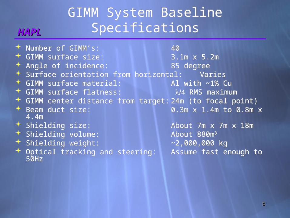
Number of GIMM’s: 40 GIMM surface size: 3.1m x 5.2m Angle of incidence: 85 degree Surface orientation from horizontal: Varies GIMM surface material: Al with ~1% Cu GIMM surface flatness: RMS maximum GIMM center distance from target: 24m (to focal point) Beam duct size: 0.3m x 1.4m to 0.8m x
4.4m Shielding size: About 7m x 7m x 18m Shielding volume: About 880m3
Shielding weight: ~2,000,000 kg Optical tracking and steering: Assume fast enough to
50Hz

99
HAPLHAPLDesign ObjectivesDesign Objectives
1. Meet the optical stability requirements for the GIMM units as located within the facility
2. Meet the operational and service needs of the GIMM units
1. Meet the optical stability requirements for the GIMM units as located within the facility
2. Meet the operational and service needs of the GIMM units
1010
HAPLHAPLDesign ApproachDesign Approach
To meet the optical stability requirements the design incorporates two major elements:1.The details of the GIMM attachment to the shield block unit.
2.The facility structure supporting the individual GIMM shielding blocks.
To meet the optical stability requirements the design incorporates two major elements:1.The details of the GIMM attachment to the shield block unit.
2.The facility structure supporting the individual GIMM shielding blocks.

1111
HAPLHAPL
Facility structure supporting the individual GIMM shielding block and duct unit
Facility structure supporting the individual GIMM shielding block and duct unit
GIMM base mounting inside beam line duct
GIMM base mounting inside beam line duct
1212
HAPLHAPLPrimary Design ChallengePrimary Design Challenge
The primary design challenge is maintaining the GIMM surface location with respect to the optical beam path.
The primary design challenge is maintaining the GIMM surface location with respect to the optical beam path.
1313
HAPLHAPLFocal Point Error AnalysisFocal Point Error Analysis
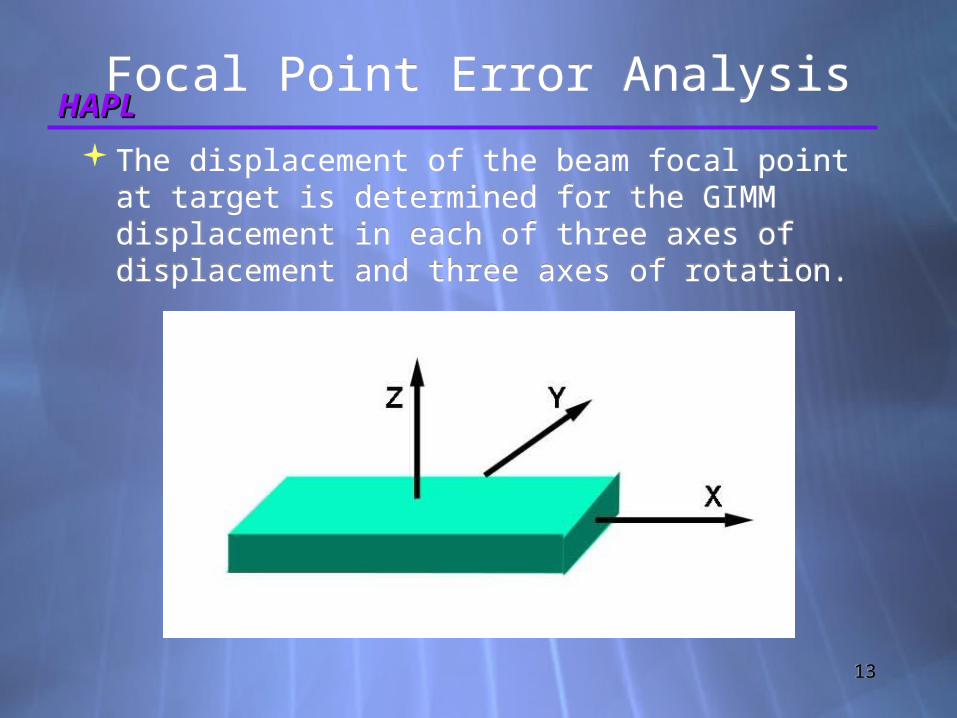
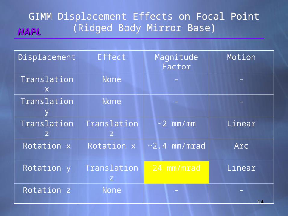
The displacement of the beam focal point at target is determined for the GIMM displacement in each of three axes of displacement and three axes of rotation.
The displacement of the beam focal point at target is determined for the GIMM displacement in each of three axes of displacement and three axes of rotation.
1414
HAPLHAPL
GIMM Displacement Effects on Focal Point(Ridged Body Mirror Base)
GIMM Displacement Effects on Focal Point(Ridged Body Mirror Base)
Displacement Effect Magnitude Factor
Motion
Translation x
None - -
Translation y
None - -
Translation z
Translation z
~2 mm/mm Linear
Rotation x Rotation x ~2.4 mm/mrad Arc
Rotation y Translation z
24 mm/mrad Linear
Rotation z None - -

1515
HAPLHAPL
Low Frequency Displacement Effects
Low Frequency Displacement Effects
Design assumes low frequency (<50Hz) and small amplitude displacements will be compensated by the active tracking and steering system.
Examples:Thermal variations of structural elements
All low frequency sources of vibration
Structural settling
Design assumes low frequency (<50Hz) and small amplitude displacements will be compensated by the active tracking and steering system.
Examples:Thermal variations of structural elements
All low frequency sources of vibration
Structural settling
1616
HAPLHAPL
Compensation for Low Frequency Effects
Compensation for Low Frequency Effects
All elements in the optical system must be designed with:Sufficient static adjustment rangeSufficient dynamic range for an effective steering system.Beam duct aperture sizeWindow aperture sizeMirror surface size
All elements in the optical system must be designed with:Sufficient static adjustment rangeSufficient dynamic range for an effective steering system.Beam duct aperture sizeWindow aperture sizeMirror surface size
1717
HAPLHAPLMirror Base Design GoalsMirror Base Design Goals
1. Manageable mirror base size – in line with standard commercial equipment
2. Isolate mirror base from beam vacuum duct
3. High attenuation factor for frequencies above 50Hz using vibration isolation
4. Minimum mirror base fundamental frequencies >400Hz (achievable with the nine smaller mirror segments)
5. Use commercial off the shelf (COTS) equipment directly or modified to meet the unique environment

1818
HAPLHAPL
GIMM Shielding Block Unit Section
GIMM Shielding Block Unit Section

1919
HAPLHAPL
GIMM Base Support System Details
GIMM Base Support System Details
Each GIMM face is divided into 3x3 array of GIMM segment faces (this provides a more manageable size and the ability to use COTS components).
Each GIMM segment is mounted on a segment base (~1.1m x ~1.8m) constructed from stainless steel or SiC in a honey comb configuration and incorporating active cooling.
Each base is mounted on frame with legs passing through the wall of the vacuum vessel and sealed with welded bellows.
The legs for each GIMM segment are joined together outside of the vacuum chamber with a robust table structure.
The table structure is directly mounted on vibration isolators.
The isolators are directly anchored into the surrounding concrete structure.

2020
HAPLHAPLGIMM Isolated Base SupportGIMM Isolated Base Support
2121
HAPLHAPLMajor Structure Design GoalsMajor Structure Design Goals
1. Meet the static load requirements for reactor core infrastructure
2. Stable foundation below grade located at a suitable site
3. A ridged structure encompassing the long beam paths
4. Structure must have a high damping factor and low transmissibility
5. Main structure fundamental modes of >10Hz
6. Meet Vibration Criteria standards VC-E and NIST-A1 or better classifications
7. Attenuate all detrimental sources of vibration through isolation

2222
HAPLHAPLDesign Development CriteriaDesign Development Criteria
Basic structural elements considered:Static loadingLoad to foundationFundamental modes of vibrationHorizontal and vertical dynamic stabilityVibration dampeningArch constructionConcrete vs. steel
Designs developed for other low vibration facilities:NIST Advanced Measurement LaboratoryNew semiconductor, metrology and nanotechnology buildings

2323
HAPLHAPL
Initial Investigation of Structural Stability
Initial Investigation of Structural Stability
Stainless Steel Frame FEA Cylindrical Concrete Arch FEA

2424
HAPLHAPL
Steel Frame Supporting Large Mass
Steel Frame Supporting Large Mass
Large static deformations (>> 1-inch)
Numerous low frequency modes <10 Hz.
Prone to buckling and other instabilities
Conclusion – Unrealistically massive steel structures would be required to reduce these effects to an acceptable level
Large static deformations (>> 1-inch)
Numerous low frequency modes <10 Hz.
Prone to buckling and other instabilities
Conclusion – Unrealistically massive steel structures would be required to reduce these effects to an acceptable level 1st Mode << 1 Hz.
2525
HAPLHAPL
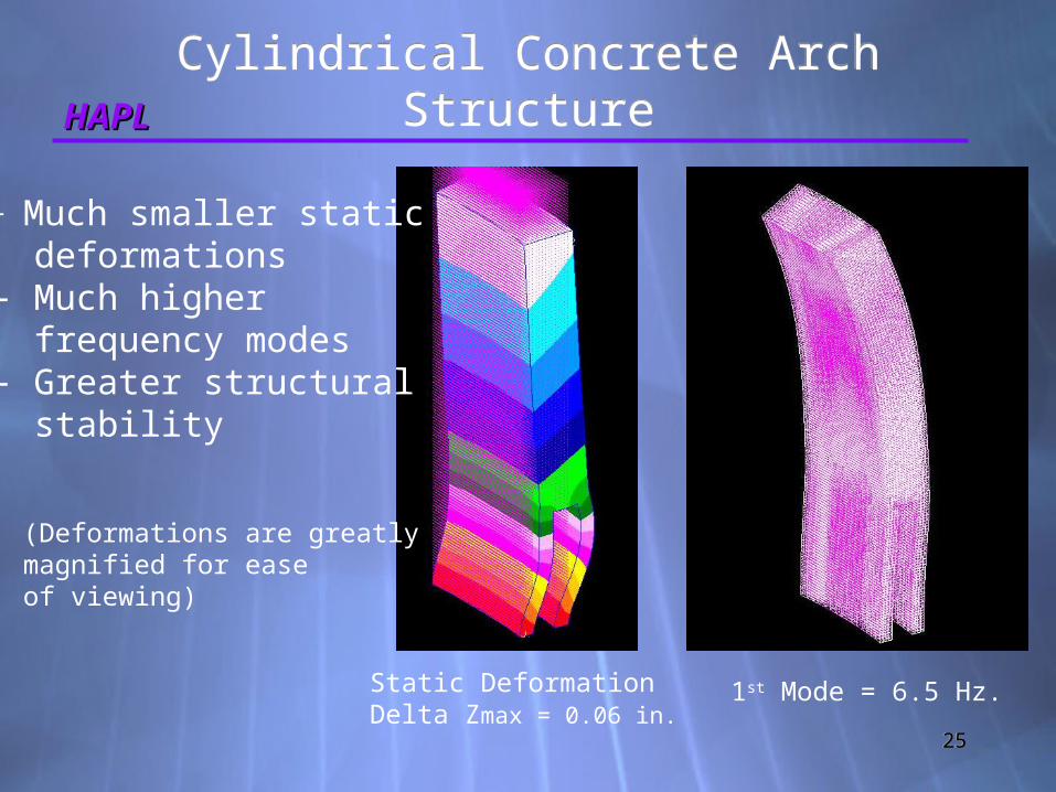
Cylindrical Concrete Arch Structure
Cylindrical Concrete Arch Structure
1st Mode = 6.5 Hz.Static DeformationDelta Zmax = 0.06 in.
- Much smaller static deformations- Much higher frequency modes- Greater structural stability
(Deformations are greatlymagnified for ease of viewing)

2626
HAPLHAPL
Integrated Facility StructureIntegrated Facility Structure

2727
HAPLHAPL
Advantages of Concrete Arch Construction
Advantages of Concrete Arch Construction
Reduction in material volumeProvides service paths and accessGood stability and strength to weight ratio
Established and proven technologyReduced resonance peaks, minimizes node points
Cost advantages
Reduction in material volumeProvides service paths and accessGood stability and strength to weight ratio
Established and proven technologyReduced resonance peaks, minimizes node points
Cost advantages
2828
HAPLHAPL
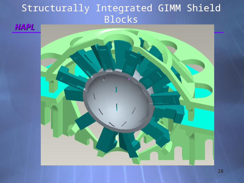
Structurally Integrated GIMM Shield Blocks
Structurally Integrated GIMM Shield Blocks

2929
HAPLHAPL
Advantages of Proposed Configuration
Advantages of Proposed Configuration
Employment of concrete in this manner provides an elegant solution.
Concrete performs the dual roles of shielding material and structural material
Constructing the intervening structural elements from concrete provides for a continuous homogeneous structure with the shielding and foundation.
Eliminates connection points and nodes between different structural materials.
Provides good damping characteristics. Provides higher fundamental modes than steel
framing. Provides the ability to cast shapes as
required. This configuration provides a stable platform. Utilizes proven commercial construction
methods.

3030
HAPLHAPLSection View of StructureSection View of Structure

3131
HAPLHAPL
Comparison of Concrete Volume in Selected Power Facilities
Comparison of Concrete Volume in Selected Power Facilities
FACILITY VOLUME OF CONCRETE m3
PRODUCED POWER Gw
Hoover Dam 3,333,000 2
Fission Plant 305,000 1
HAPL IFE Plant
~400,000 2

3232
HAPLHAPLFuture workFuture work
Complete static loading analysisDetailed dynamic vibration analysisVibration isolator designA further refinement in the integration of the GIMM shield units into the structure
GIMM cooling methods minimizing vibration
Servicing featuresIntegrated facility structural details
Dust mitigation and removal
3333
HAPLHAPLConclusionsConclusions
This design strategy provides a scalable and flexible approach to meeting the structural requirements of an evolving project.
This design efficiently incorporates the required shielding materials into the core structure providing increased stability and functionality
This design rigidly binds together critical components and infrastructure while minimizing the effects vibration.

3434
HAPLHAPL

3535
HAPLHAPL
For Additional Information Please See
Poster
For Additional Information Please See
Poster

3636
HAPLHAPL
Extra Materials for PosterExtra Materials for Poster

3737
HAPLHAPLSources of VibrationSources of Vibration
Reducing the sources of vibration to an minimum is as important as the attenuation of vibration.
Sources of vibration grouped by strength of coupling to the GIMM:Sources acting directly on the GIMM.IFE Process sources acting on the central core structure.
Facility and other sources dispersed throughout the plant.

3838
HAPLHAPL
Sources of Vibration Acting Directly on the GIMM
Sources of Vibration Acting Directly on the GIMM
Thermal shock from target detonationImpulse at rate ~5Hz
Thermal shock from laser pulseImpulse at rate ~5Hz
Flow of GIMM coolantContinuous source
Electromagnetic effectsTo be determined
Thermal shock from target detonationImpulse at rate ~5Hz
Thermal shock from laser pulseImpulse at rate ~5Hz
Flow of GIMM coolantContinuous source
Electromagnetic effectsTo be determined

3939
HAPLHAPL
IFE Process Sources of Vibration Through the Facility
Structure
IFE Process Sources of Vibration Through the Facility
StructureTarget detonation impulse
Ion, radiation and thermal impulse at ~5Hz
Magnetic Intervention field pulseField force response into structure at ~5Hz
Target detonation impulseIon, radiation and thermal impulse at ~5Hz
Magnetic Intervention field pulseField force response into structure at ~5Hz

4040
HAPLHAPL
Facility and Other Sources of Vibration
Facility and Other Sources of Vibration
Rotating machinery: pumps, motors, etc.
Valves operatingFluid flow through pipesTransformers and other electrical devices
Elevators, cranes, trucks, doorsExternal sources through foundation
Atmospheric and Seismic
Rotating machinery: pumps, motors, etc.
Valves operatingFluid flow through pipesTransformers and other electrical devices
Elevators, cranes, trucks, doorsExternal sources through foundation
Atmospheric and Seismic

4141
HAPLHAPLOther GIMM IssuesOther GIMM Issues
Dust and Contamination IssuesSuitable Vibration IsolatorsServicing Issues
Dust and Contamination IssuesSuitable Vibration IsolatorsServicing Issues

4242
HAPLHAPL
GIMM Dust and Contamination Issues
GIMM Dust and Contamination Issues
GIMM surface contamination from dust and other materials can compromise the performance of the mirror
The beam ducts will probably be a source of contamination
Counter gas flows may introduce excessive gas loading on the pumps and fuel recovery system to be effective
Electrostatic collection may be of some value
4343
HAPLHAPLVibration IsolatorsVibration Isolators
Use COTS components when possible Solid elastomer units can not be used do to the
harsh radiation environment Pneumatic units:
COTS units will probably work in the radiation environment with some modification and the removal of elastomer seals
Typical load capability of 2000 lb per unit Non magnetic versions available Typical attenuation factor of >100 for both
horizontal and vertical frequencies >30Hz (multi-staging can be used to reach greater attenuation factors)
Non vertical applications: COTS units will require some modification for non
vertical use It may be possible to use vertical vibration
isolators with counterbalanced support frame
4444
HAPLHAPLServicing IssuesServicing Issues
Access to GIMM for:Adjustment and inspectionMaintenance and cleaningCooling system serviceUnit replacementMaterial and equipment
Beam vacuum duct penetrationsRemote servicing possibilities
Access to GIMM for:Adjustment and inspectionMaintenance and cleaningCooling system serviceUnit replacementMaterial and equipment
Beam vacuum duct penetrationsRemote servicing possibilities