Embed Size (px)
Citation preview

Washington University in St. Louis Washington University in St. Louis
Washington University Open Scholarship Washington University Open Scholarship
Washington University / UMSL Mechanical Engineering Design Project JME 4110 Mechanical Engineering & Materials Science
Summer 2016
JME 4110 Final Report -Trunk Lift Assist JME 4110 Final Report -Trunk Lift Assist
Thomas Schuh Washington University in St. Louis, [email protected]
Ben Hogen Washington University in St. Louis, [email protected]
Kyle Copeland Washington University in St. Louis, [email protected]
Jon Krems Washington University in St. Louis, [email protected]
Follow this and additional works at: https://openscholarship.wustl.edu/jme410
Recommended Citation Recommended Citation Schuh, Thomas; Hogen, Ben; Copeland, Kyle; and Krems, Jon, "JME 4110 Final Report -Trunk Lift Assist" (2016). Washington University / UMSL Mechanical Engineering Design Project JME 4110. 4. https://openscholarship.wustl.edu/jme410/4
This Final Report is brought to you for free and open access by the Mechanical Engineering & Materials Science at Washington University Open Scholarship. It has been accepted for inclusion in Washington University / UMSL Mechanical Engineering Design Project JME 4110 by an authorized administrator of Washington University Open Scholarship. For more information, please contact [email protected].

This document presents the design for device to assist with loading and unloading of items into
the trunk compartment of an automobile. Enclosed in this report is the rationale behind the
design decisions based on consumer interviews, relevant regulating codes and standards, and
necessary design constraints. Initial concept drawings and the selection process leading to the
initial embodiment design are contained in this report. All initial and final CAD drawings and
assembly instructions are incorporated into this summary statement as well as photographs and
video links.
JME 4110
Design
Report
Trunk Lift Assist
Kyle Copeland
Benjamin Hogan
Jon Krems
Tom Schuh

Page 2 of 103
TABLE OF CONTENTS
List of Figures ............................................................................................................................. 5
List of Tables ............................................................................................................................... 6
1 Introduction ............................................................................................................................. 7
1.1 Value Proposition ............................................................................................................ 7
1.2 Team Members ................................................................................................................ 7
2 Background Information Study ............................................................................................... 7
2.1 Design Brief .................................................................................................................... 7
2.2 Background Summary ..................................................................................................... 8
3 Concept Design and Specification ......................................................................................... 10
3.1 User Needs, Metrics, and Quantified Needs Equations. ................................................ 10
3.1.1 User Needs Interview ............................................................................................ 10
3.1.2 Identified Metrics .................................................................................................. 12
3.1.3 Quantified Needs Equations .................................................................................. 13
3.2 Concept Drawings ......................................................................................................... 14
3.3 Concept Selection Process. ............................................................................................ 18
3.3.1 Concept Scoring .................................................................................................... 18
3.3.2 Physical Feasibility Analysis ................................................................................. 22
3.3.3 Final Summary Statement ..................................................................................... 23
3.4 Proposed Performance Measures................................................................................... 23
3.5 Revised Specifications................................................................................................... 24
4 Embodiment and Fabrication Plan ........................................................................................ 27
4.1 Embodiment/Assembly drawing ................................................................................... 27
4.2 Parts List ........................................................................................................................ 28
4.3 Draft Detail Drawings ................................................................................................... 29
4.4 Design Rationale ........................................................................................................... 45
5 Engineering Analysis............................................................................................................. 47
5.1 Engineering Analysis Proposal ...................................................................................... 47
5.1.1 Engineering Analysis Contract .............................................................................. 47

Page 3 of 103
5.2 Engineering analysis results .......................................................................................... 48
5.2.1 Motivation ............................................................................................................. 48
5.2.2 Analysis Summary ................................................................................................. 48
5.2.3 Methodology.......................................................................................................... 48
5.2.4 Results ................................................................................................................... 49
5.2.5 Significance ........................................................................................................... 50
6 Risk Assessment .................................................................................................................... 51
6.1 Risk Identification ......................................................................................................... 51
6.2 Risk Assessment ............................................................................................................ 51
6.2.1 Supply Chain ......................................................................................................... 51
6.2.2 Funding .................................................................................................................. 51
6.2.3 Fabrication ............................................................................................................. 52
6.2.4 Manufacturing Facilities ........................................................................................ 52
6.2.5 Product Liability .................................................................................................... 52
6.3 Risk Mitigation .............................................................................................................. 52
6.3.1 Supply Chain ......................................................................................................... 52
6.3.2 Funding .................................................................................................................. 53
6.3.3 Fabrication ............................................................................................................. 53
6.3.4 Manufacturing Facilities ........................................................................................ 53
6.3.5 Product Liability .................................................................................................... 54
7 Codes and Standards.............................................................................................................. 55
7.1 Identification ................................................................................................................. 55
7.2 Justification ................................................................................................................... 58
7.3 Design Constraints......................................................................................................... 58
7.4 Significance ................................................................................................................... 59
8 Working Prototype ................................................................................................................ 60
8.1 Prototype ....................................................................................................................... 60
8.2 Prototype Video ............................................................................................................. 61
8.3 Specific Prototype Components .................................................................................... 61
9 Design Documentation .......................................................................................................... 63
9.1 Final Drawings and Documentation .............................................................................. 63
9.1.1 Final Engineering Drawings .................................................................................. 63
9.1.2 Sourcing Instructions ............................................................................................. 98

Page 4 of 103
9.2 Final Presentation .......................................................................................................... 98
9.3 Teardown ....................................................................................................................... 99
10 Appendix A - Parts List ................................................................................................... 100
11 Appendix B - Bill of Materials ........................................................................................ 102
12 Appendix C – Final CAD models ................................................................................... 102
13 Annotated Bibliography .................................................................................................. 103
Page 5 of 103
LIST OF FIGURES
Figure 1 - Patent Example 1 ............................................................................................................ 8
Figure 2 - Patent Example 2 ............................................................................................................ 9
Figure 3 - Concept 1 Drawing ....................................................................................................... 14
Figure 4 - Concept 2 Drawing ....................................................................................................... 15
Figure 5 - Concept 3 Drawing ....................................................................................................... 16
Figure 6 - Concept 4 Drawing ....................................................................................................... 17
Figure 7 - Embodiment/Assembly Drawing .................................................................................. 27
Figure 8 - Winch Shaft FEA Results ............................................................................................. 49
Figure 9 - Drive Arm and Shaft FEA Results ............................................................................... 50
Figure 10 - Retracted TLA ............................................................................................................ 60
Figure 11 - Extended TLA ............................................................................................................ 60
Figure 12 - TLA Retracted Profile ................................................................................................ 61
Figure 13 - TLA Drive Motor ....................................................................................................... 61
Figure 14 - TLA Dual Drive Chain ............................................................................................... 62
Figure 15 - TLA Limit Switches ................................................................................................... 62

Page 6 of 103
LIST OF TABLES
Table 1 - User Needs Interview ..................................................................................................... 10
Table 2 - Identified Metrics ........................................................................................................... 12
Table 3 - Quantified Needs Matrix ................................................................................................ 13
Table 4 - Concept 1 Quantified Needs Matrix .............................................................................. 18
Table 5 - Concept 2 Quantified Needs Matrix .............................................................................. 19
Table 6 - Concept 3 Quantified Needs Matrix .............................................................................. 20
Table 7 - Concept 4 Quantified Needs Matrix .............................................................................. 21
Table 8 - Metrics Table for Trunk Lift Assist (TLA) Revised ...................................................... 24
Table 9 - Needs Table for Trunk Lift Assist (TLA) Revised ........................................................ 25
Table 10 - Concept 1 Revised Quantified Needs Matrix ............................................................... 26
Table 11 - Initial Parts List ............................................................................................................ 28
Table 12 – Part No 00001 Final Parts List .................................................................................. 100
Table 13 - Part No 00002 Final Parts List ................................................................................... 101
Table 14 - Part No 00003 Final Parts List ................................................................................... 101
Table 15 - Part No 00004 Final Parts List ................................................................................... 101
Table 16 - Part No 00005 Final Parts List ................................................................................... 101
Table 17 - Final BOM with Sourcing Information ...................................................................... 102
Page 7 of 103
1 INTRODUCTION
1.1 VALUE PROPOSITION
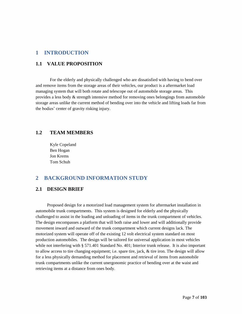
For the elderly and physically challenged who are dissatisfied with having to bend over
and remove items from the storage areas of their vehicles, our product is a aftermarket load
managing system that will both rotate and telescope out of automobile storage areas. This
provides a less body & strength intensive method for removing ones belongings from automobile
storage areas unlike the current method of bending over into the vehicle and lifting loads far from
the bodies’ center of gravity risking injury.
1.2 TEAM MEMBERS
Kyle Copeland
Ben Hogan
Jon Krems
Tom Schuh
2 BACKGROUND INFORMATION STUDY
2.1 DESIGN BRIEF
Proposed design for a motorized load management system for aftermarket installation in
automobile trunk compartments. This system is designed for elderly and the physically
challenged to assist in the loading and unloading of items in the trunk compartment of vehicles.
The design encompasses a platform that will both raise and lower and will additionally provide
movement inward and outward of the trunk compartment which current designs lack. The
motorized system will operate off of the existing 12 volt electrical system standard on most
production automobiles. The design will be tailored for universal application in most vehicles
while not interfering with § 571.401 Standard No. 401; Interior trunk release. It is also important
to allow access to tire changing equipment; i.e. spare tire, jack, & tire iron. The design will allow
for a less physically demanding method for placement and retrieval of items from automobile
trunk compartments unlike the current unergonomic practice of bending over at the waist and
retrieving items at a distance from ones body.

Page 8 of 103
2.2 BACKGROUND SUMMARY
A search for existing designs that were similar to our chosen topic lead to two patents that
are shown in the figures below.
Figure 1 - Patent Example 1

Page 9 of 103
Figure 2 - Patent Example 2

Page 10 of 103
3 CONCEPT DESIGN AND SPECIFICATION
3.1 USER NEEDS, METRICS, AND QUANTIFIED NEEDS EQUATIONS.
3.1.1 User Needs Interview
Table 1 - User Needs Interview
Project/Product Name: Trunk Lift Assist (TLA) Customer: Dr. Mark Jakiela Address: Washington University Willing to do follow up? Yes Type of user: Elderly & Physically Challenged
Interviewer(s): Kyle Copeland, Ben Hogan, Jon Krems, & Tom Schuh Date: 06/12/16 Currently uses: Non-ergonomic Physical Ability
Question Customer Statement Interpreted Need Importance
How much weight do you need this to lift?
A full weeks worth of groceries, which includes several gallon jugs of stuff. I would guess that 60-70 lbs is a good number.
Can lift a full week’s worth of groceries
5
What height would you prefer the unloading deck to reach?
So I can take stuff off of if without bending. No less than countertop (36”) and probably no need for higher than 60”
Can raise loads above user’s waist
5
What kinds of items do you need assistance with?
I want it to safely contain and hoist a typical grocery haul. So, some heavier and more awkward stuff but a large number items. Another use is large bags of pet supplies (e.g. guinea pig bedding, etc.) This would be smaller number of larger heavier items.
Can hold a large number of smaller items Can hold a small number of large items
4
How often do you Every trip to the Can operate many 5

Page 11 of 103
intend to use this? grocery store at least, in addition to other uses. 3-4 times / week.
times per week
Will access to the spare tire & associated tools be imperative?
No, flats are rare enough that I think we can run that risk.
Can access spare tire/tool compartment
1
What kind of vehicle do you vision using this item on?
SUV’s for sure, as well as the trunks of sedans. Coupes (hatchbacks) not necessary.
Can install in any type of vehicle
4
How fast do you prefer the lift to operate?
All stuff, in one load, into or out of trunk in 5-10 seconds. Can be slower if need be. Fast not critical.
Can cycle quickly 2
Do you intend this to be a permanent installation?
Semi permanent. When installed, likely to leave it there. Maybe remove for making a trip with lots of luggage. Definitely an aftermarket product.
Can be removed quickly and easily if/when needed
2
Where do you intend to purchase this device?
Online. Possibly at wheelchair distributors, etc. Maybe eventually big box places (WalMart, AutoZone)
Can be purchased online
2
How far do you expect this item to protrude from the trunk compartment?
I see it as a platform with the footprint of a shopping cart. That footprint (2’X 3’) should not overlap the car’s footprint. Should be able to walk around three sides of platform.
Can extend out of the trunk
3
How large should the 2’ X 3’ minimum. See Has adequate lifting 5
Page 12 of 103
lift area be?
above. area
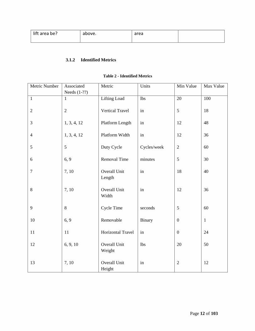
3.1.2 Identified Metrics
Table 2 - Identified Metrics
Metric Number Associated
Needs (1-??)
Metric Units Min Value Max Value
1
2
3
4
5
6
7
8
9
10
11
12
13
1
2
1, 3, 4, 12
1, 3, 4, 12
5
6, 9
7, 10
7, 10
8
6, 9
11
6, 9, 10
7, 10
Lifting Load
Vertical Travel
Platform Length
Platform Width
Duty Cycle
Removal Time
Overall Unit
Length
Overall Unit
Width
Cycle Time
Removable
Horizontal Travel
Overall Unit
Weight
Overall Unit
Height
lbs
in
in
in
Cycles/week
minutes
in
in
seconds
Binary
in
lbs
in
20
5
12
12
2
5
18
12
5
0
0
20
2
100
18
48
36
60
30
40
36
60
1
24
50
12

Page 13 of 103
3.1.3 Quantified Needs Equations
Table 3 - Quantified Needs Matrix

Page 14 of 103
3.2 CONCEPT DRAWINGS
Figure 3 - Concept 1 Drawing

Page 15 of 103
Figure 4 - Concept 2 Drawing

Page 16 of 103
Figure 5 - Concept 3 Drawing

Page 17 of 103
Figure 6 - Concept 4 Drawing

Page 18 of 103
3.3 CONCEPT SELECTION PROCESS.
3.3.1 Concept Scoring
Concept #1 Scoring
Table 4 - Concept 1 Quantified Needs Matrix

Page 19 of 103
Concept #2 Scoring
Table 5 - Concept 2 Quantified Needs Matrix

Page 20 of 103
Concept #3 Scoring
Table 6 - Concept 3 Quantified Needs Matrix

Page 21 of 103
Concept #4 Scoring
Table 7 - Concept 4 Quantified Needs Matrix

Page 22 of 103
3.3.2 Physical Feasibility Analysis
Concept #1
This concept is probably the most feasible of the four. The electric winch will be the
only costly material used in the building of concept 1. We decided that the top platform can be
made from inexpensive wire shelving and the rest would be made from steel. The availability of
differing sizes of wire shelving platforms allows a myriad of different sized applications for
differing vehicles. This means we would be able to bring an affordable and adaptable item to
market. We will require a relatively strong winch to overcome the initial lift of the platform
when loaded, but there are plenty of options that are in our budget. The rest of the hardware and
materials are easily purchased and fabricated for assembly of this concept
Concept #2
This concept uses an electric motor and a worm drive to lift the top platform. A
worm/screw drive can be difficult to fabricate or may be difficult to find. He precision required
for the worm/screw drive could lead to challenges that may hinder the overall design. These can
be heavy and require a strong electric motor. This design also relies on a large turn-top bearing
and platform for added accessibility. While a large platform bearing is available to handle a
potential loading on the shelf, the force required to rotate the shelf may be beyond the capability
of the user. Another challenge involved with this design is the straight vertical lift will both limit
the size of the platform and the application range of vehicles.
Concept #3
Concept 3 requires an air compressor and tank to fill airbags that lift the top platform.
This system can be expensive and it is difficult to control the air flow to lift the bags slowly and
evenly. This design might also have stability problems once the bags are inflated. As with
concept #2, the straight vertical operation of the unit will not be accommodated by many vehicles
leading to very limited applications.
Concept #4
Concept 4 requires drilling holes and bolting the device to the floor of the trunk. This
means it will be more of a permanent installation. The tower/pulley design limits the height that
the platform can be raised in the trunk. The actual pivoting of the unit to the exterior from the
storage space also presented challenges that interfered with the lifting mechanism. This concept
required very specific parameters that were only available on a limited number of vehicles.

Page 23 of 103
3.3.3 Final Summary Statement
When considering the user needs scoring, feasibility of building, and project budget,
concept #1 stands out as the winner of the concept selection. This concept had the highest user
needs score of the four with the score of 61.2. We are relying on an electric winch and chain
drive which is a relatively easy and reliable method for transferring torque. The remaining
materials for the build are easily obtainable and do not require any difficult machining. We
should be able to fabricate, assemble, and test the design with plenty of time for adjustments and
multiple iterations. This design gives us the opportunity to build something that is actually
affordable and could be a real consumer product.
The remaining 3 concepts were obviously workable but did not meet the needs of our
user. The limited applications provided by the other concepts left this group with a potentially
vehicle specific apparatus with limited application.
3.4 PROPOSED PERFORMANCE MEASURES
The overall performance measure that requires the unit to be able to lift and accommodate
a week’s worth of groceries uncovered some deficiencies in our design. Following selection of
concept #1 as our final design, certain specifications had to be addressed. The requirement to be
able to both lift and protrude from the interior cargo area and the constraints provided by vehicles
immediately presented design challenges. The need for a large platform, which could also be
adaptable to a variety of vehicles, led to the desire to use interchangeable shelving for the
platform. The force required to actuate the device had to be addressed due to the initial torque
required to begin the lifting motion. The challenges presented by the constraints of the trunk
opening, the load lifting requirements, and the overall motion both up and out of the storage
compartment had to be addressed. The desired concept is adaptable which allows the
accommodation of the overall performance measure, load size and weight, while providing for
many of the needs discovered in the needs and concept generation.

Page 24 of 103
3.5 REVISED SPECIFICATIONS
Table 8 - Metrics Table for Trunk Lift Assist (TLA) Revised
Metric
Number
Associated
Need Metric Units Min Value Max Value
1 1 Lifting Load lbs 50 75
2 2 Vertical Travel in 5 18
3 1,3,4,12,13 Platform Length in 20 36
4 1,3,4,12,13 Platform Width in 12 24
5 5 Duty Cycle Cycles/week 2 60
6 6,9 Removal Time Minutes 5 30
7 7,10 Overall Unit Length in 18 40
8 7,10 Overall Unit Width in 12 36
9 8 Cycle Time Seconds 5 60
10 6,9 Removable Binary 0 1
11 11 Horizontal Travel in 0 24
12 6,9,10 Overall Unit Weight lbs 20 50
13 7,10 Overall Unit Height in 6 12
14 14 Cart Holder Binary 0 1

Page 25 of 103
Table 9 - Needs Table for Trunk Lift Assist (TLA) Revised
Need Number Need Importance
1 TLA can lift a full week’s worth of groceries 5
2 TLA can raise loads above user’s waist 5
3 TLA can hold a large number of smaller items 4
4 TLA can hold a small number of large items 4
5 TLA can operate many times per week 5
6 TLA can provide access to spare tire/ tool
compartment
1
7 TLA can be installed in any type of vehicle 4
8 TLA can fully cycle quickly 2
9 TLA can be removed quickly and easily if/when
needed
2
10 TLA can be purchased online 2
11 TLA can extend out of the trunk 3
12 TLA has adequate lifting area 5
13 TLA has interchangeable lifting platforms 4
14 TLA is able to hold shopping cart securely 3

Concept #1 Revised Scoring
Table 10 - Concept 1 Revised Quantified Needs Matrix

4 EMBODIMENT AND FABRICATION PLAN
4.1 EMBODIMENT/ASSEMBLY DRAWING
Figure 7 - Embodiment/Assembly Drawing

Page 28 of 103
4.2 PARTS LIST
Table 11 - Initial Parts List

Page 29 of 103
4.3 DRAFT DETAIL DRAWINGS

Page 30 of 103

Page 31 of 103
Page 32 of 103

Page 33 of 103

Page 34 of 103

Page 35 of 103

Page 36 of 103

Page 37 of 103

Page 38 of 103

Page 39 of 103

Page 40 of 103

Page 41 of 103

Page 42 of 103

Page 43 of 103

Page 44 of 103

Page 45 of 103
4.4 DESIGN RATIONALE
1. Frame Base Tube: This component was initially designed using 1/8”x1-1/2”x1-1/2” steel
angle. Because of any possible side loading, it was thought that this would not add enough
rigidity to the assembly, so it was recommended to weld bosses into the upright of the angle
where the links connected. Instead of this, 1-1/2”x1-1/2”x11 GA steel tubing was chosen to
reduce the complexity of the part (no welding required) and achieve the same effect.
2. Inner Parallel Link Bar: 1/8” A36 steel plate was chosen for the inner link bars. A36 was
chosen because of its good weldability, which is needed because 1 set of the inner links will
be welded to the drive shaft that will actuate the lift up and down.
3. Platform Frame Tube: Same rational as 1. Frame Base Tube:
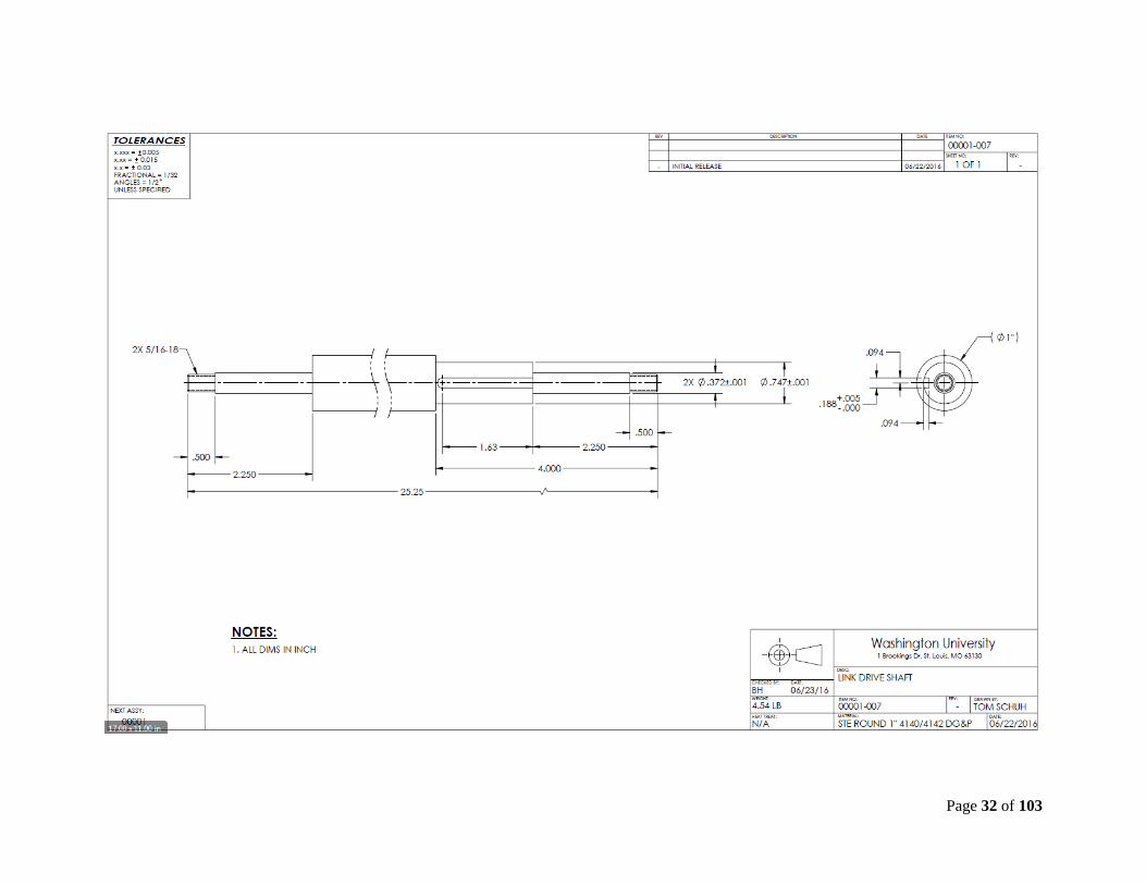
4. Link Drive Shaft: 1” 4140/4142 steel round stock was chosen for the drive shaft. The size
was determined by the size of the sprockets used, giving enough material to add shoulders for
locating. The material itself was chosen because it was in stock and “donated”. The added
strength is also a plus over low carbon steel as this will see quite a bit of bending force from
the chain drive.
5. Mounting Tube: 1-1/2”x1-1/2”x11 GA steel tubing was chosen for the mount tube for two
main reasons: 1 – it needed to be rigid enough to span the depth of the frame and support the
force that would be applied to the center of it for mounting and 2 – it was the same as the
frame and platform tubes, which reduced cost by not having to pay a premium for a small
piece of material.
6. Outer Parallel Link angle: 1/8”x1”x1” steel angle was used for the outer parallel link bars.
Angle was chosen over plate on the outer links to add strength in the transverse direction to
counter any possible side loading the unit may see.
7. Drive Shaft Key: 3/16”x3/16” key stock was chosen to fit the standard keyway size in the
chosen sprockets.
8. Stop Block: 3/8” AR36 steel plate was chosen for the stop blocks for its weldability.
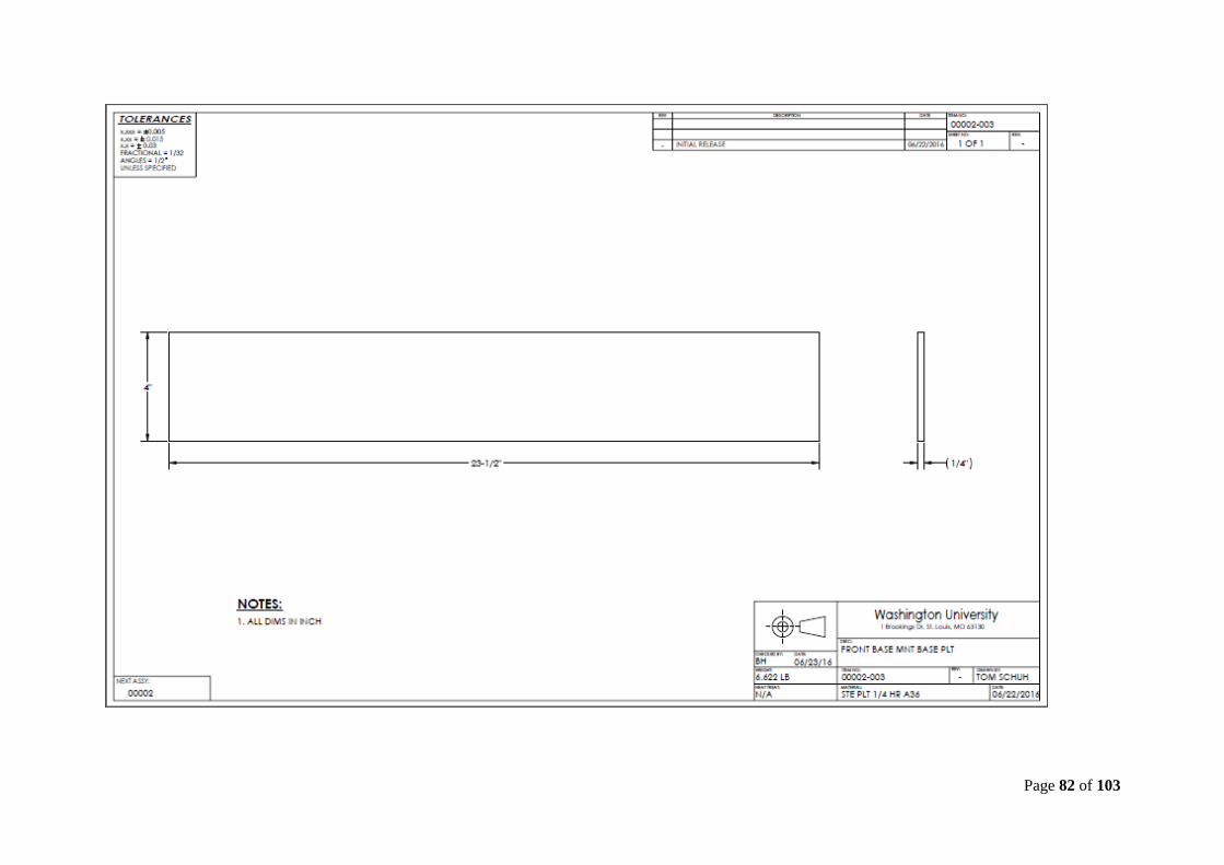
9. Front Base Mount: 1/8”x1”x1” steel angle was used for the front base mount to add rigidity
and save weight and cost over tubing.
10. Rear Base Mount: Save rational as the front base mount.
11. ANSI #40 Roller Sprocket: A single #35 sprocket was shown in the initial design. After
some analysis, it was found that a single #35 sprocket/chain would not be strong enough, so
2x #40 sprockets were chosen, using the largest diameter we could find to fit into our design
envelope.
12. ¼-20 U-Bolt: Chosen for its correct size to hold down our wire platform.
13. 24”x36” Heavy Duty Wire Shelf: Chosen for its strength, low cost and size flexibility.
14. ANSI #40H Roller Chain: Our design required that we would be able to lift a load of 75lbs.
Under maximum loading conditions, we could see a required torque of 834in-lbs, which
translates to and tensile force of 940lbs that the chain would have exerted on it. A single
strand #40H roller chain has a “working load” of 1030 lbs. We wanted to add in a factor of
safety of roughly 2, so we doubled up the number of chains. This is quite redundant,

Page 46 of 103
considering the “working load” of the chain has a factor of safety of about 4:1 built into it
already, but we wanted to make sure that the drive chains would not be a point of failure.
15. ANSI #40H Connecting Link: Sized to match chain.
16. 12V DC 2500lb Winch: Sized to meet the lift requirement with roughly a factor of safety of
2:1.
17. 5/16”-18 Flanged Locknut: Smooth flanges were chosen to help distribute any transverse
loading. Locknuts were chosen to resist vibrating loose which could be a concern in the trunk
of a vehicle.
18. 5-16”-18x2-1/4” Shoulder Bolt: 3/8”x1-3/4” shoulder to take the bearing loads of the
pivoting links.
19. through 22: Various other 5/16”-18 hardware, sized for standardization across all hardware
to help reduce the number of unique hardware part numbers.
Page 47 of 103
5 ENGINEERING ANALYSIS
5.1 ENGINEERING ANALYSIS PROPOSAL
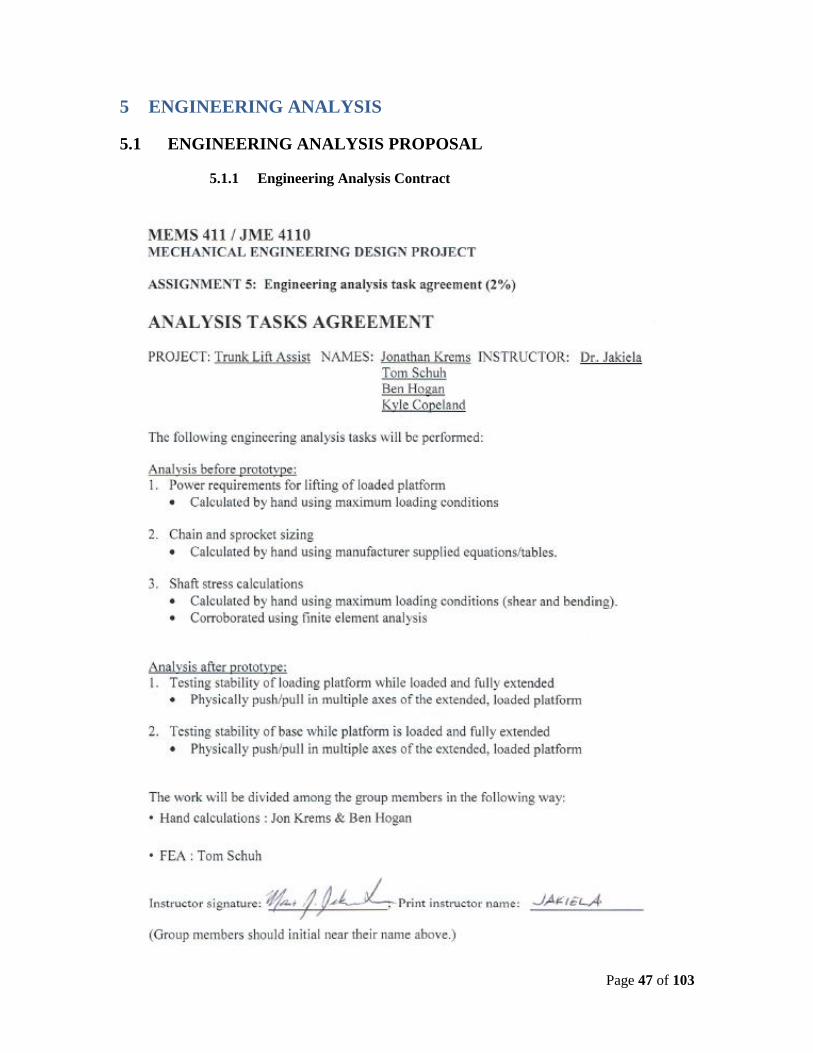
5.1.1 Engineering Analysis Contract

Page 48 of 103
5.2 ENGINEERING ANALYSIS RESULTS
5.2.1 Motivation
In order to ensure that our prototype worked without as desired, several
analysis tasks were chosen and carried out both before the prototype was built,
and after an initial version was built. Before any manufacturing was done, power
requirements for lifting the loaded platform was calculated. This was important
to the success of the design due to the 75lb lifting requirement that was set by the
user needs analysis. With the power requirements known, next it was important
to size the drive chain and sprockets, as well as the shafting sizes, to ensure they
could handle the supplied power without failure. After the initial prototype was
manufactured, several stability and rigidity tests were carried out to ensure that
the design was strong enough for everyday use.
5.2.2 Analysis Summary
For calculating the power requirements, basic static equilibrium equations
were used at maximum load and worst case positioning, ΣF = 0. The resulting
torque was then used in a standard moment equation, T = F∙r, to determine the
maximum force exerted on the drive chain. The initial torque calculated from the
static equilibrium equation was also used in the basic stress equation, σ = (T∙r)/J
After the initial prototype was built and installed, the stability and rigidity
tests were carried out by observation during use.
5.2.3 Methodology
For the analysis done prior to building the prototype, all calculations were
carried out by hand. FEA using Solidworks Simulation was carried out to
corroborate the hand calculations.
After the prototype was built and installed. It was actuated up and down
to check performance, both loaded and unloaded. In its fully extended position,
we did push/pull tests on the platform by loading it from the sides with our body
weight.

Page 49 of 103
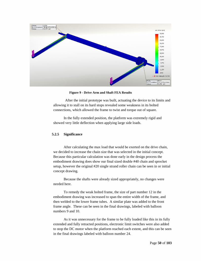
5.2.4 Results
From our calculation, using our required load of 75lbs, we determined that
a torque of 844 in∙lb was required to actuate our fully loaded platform.
Using the largest sprocket possible for our package size resulted in a moment arm
of 0.887 in. From this and the applied torque, we calculated a force of 997lb of
force that would be exerted on our drive chain.
Using the stress equation with our designed shaft size of 0.75 in, we calculated a
max stress of 10,189PSI.
The FEA results agreed with the above calculations, as well as pointing out some
other possible areas of concern, such as higher stresses in the shaft keyways as
well as higher stress concentrations in the lifting arms.
Figure 8 - Winch Shaft FEA Results
Page 50 of 103
Figure 9 - Drive Arm and Shaft FEA Results
After the initial prototype was built, actuating the device to its limits and
allowing it to stall on its hard stops revealed some weakness in its bolted
connections, which allowed the frame to twist and torque out of square.
In the fully extended position, the platform was extremely rigid and
showed very little deflection when applying large side loads.
5.2.5 Significance
After calculating the max load that would be exerted on the drive chain,
we decided to increase the chain size that was selected in the initial concept.
Because this particular calculation was done early in the design process the
embodiment drawing does show our final sized double #40 chain and sprocket
setup, however the original #20 single strand roller chain can be seen in or initial
concept drawing.
Because the shafts were already sized appropriately, no changes were
needed here.
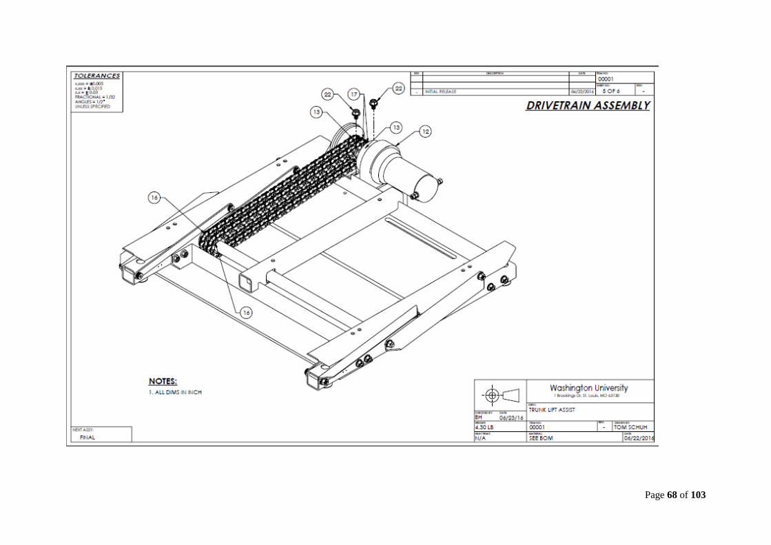
To remedy the weak bolted frame, the size of part number 12 in the
embodiment drawing was increased to span the entire width of the frame, and
then welded to the lower frame tubes. A similar plate was added to the front
frame angle. These can be seen in the final drawings, labeled with balloon
numbers 9 and 10.
As it was unnecessary for the frame to be fully loaded like this in its fully
extended and fully retracted positions, electronic limit switches were also added
to stop the DC motor when the platform reached each extent, and this can be seen
in the final drawings labeled with balloon number 24.

Page 51 of 103
6 RISK ASSESSMENT
6.1 RISK IDENTIFICATION
In the arena of product design for the Motorized Load Management System, areas
of concern have been identified. These factors enumerated below encompass the currently
foreseen hindrances to a safe and effective production of a final distributable product. It is
to be noted that this initial list is in no particular order. While this list does not necessarily
account for all outliers that could affect the project, it does contain items that would cause
a complete failure in the ability to bring the project to fruition.
Supply Chain
Funding
Fabrication
Manufacturing Facilities
Product Liability
6.2 RISK ASSESSMENT
6.2.1 Supply Chain
Risk associated with an interruption in the supply chain. This can be interpreted
as complete inability to attain the required parts by means of vendor
inconsistency or actual logistic delivery of required materials.
Probability: High
Impact: High
6.2.2 Funding
Risk associated with an interruption of proper funding for the program.
Probability: Medium
Impact: High
Page 52 of 103
6.2.3 Fabrication
Risk associated with the inability to manufacture the product based on lack of job
skill-set or availability of fabrication equipment.
Probability: Medium
Impact: Medium
6.2.4 Manufacturing Facilities
Risk associated with the loss of production based on a loss of a manufacturing
facility.
Probability: High
Impact: High
6.2.5 Product Liability
Risk associated with injury incurred by the end user of the product.
Probability: Low
Impact: High
6.3 RISK MITIGATION
6.3.1 Supply Chain
It is impossible to mitigate all problems that could occur in a supply chain. Due to
the many variables associated with a supply change interruption, it is important to source
materials from several vendors to minimize the risk to the overall production process.
We found that it was important to source standard parts to allow the ability to order from
a multitude of vendors. Elimination of specialized parts allows the flexibility to source
required materials from different vendors in the event of a service interruption by any
particular supplier.

Page 53 of 103
6.3.2 Funding
It is impossible to mitigate all problems that could occur in a revenue source stream.
It is important to retain investors that have additional available capital that are committed
to the success of the project. Obtaining and maintaining an available line of credit in the
event a distributor is unable to fulfill their financial commitments would allow the
company to bridge an unanticipated shortfall in the regular revenue stream.
6.3.3 Fabrication
Potential for machining capacity breakdown and loss of personnel is inherent
vulnerability in the production process. By cross craft training it would allow flexibility
in the event of employee absence to adjust the production capability. Machine
breakdowns as well as required maintenance can be a hindrance to the production
process. Parallel manufacturing facilities would minimize the impact of required an
unexpected loss of manufacturing capability. Maintaining additional production capacity
at parallel manufacturing facilities would allow a dynamic response to unanticipated
interruptions of the manufacturing flow.
6.3.4 Manufacturing Facilities
Unanticipated failures experienced by manufacturing facilities may be impossible
mitigate due to the nature of the failure, i.e. natural disaster, loss of utilities, etc. Based
on the potential for these failures, maintaining parallel manufacturing facilities at
multiple locations provides the protection against a complete failure in the manufacturing
process. By maintaining an updated list of alternative vacant facilities located in
reasonably close proximity to the manufacturing facility, production could be shifted in
the event that the current location becomes untenable.

Page 54 of 103
6.3.5 Product Liability
The possibility of injury and even death must be avoided at all costs. Safety
assessments by regulating bodies must be made at regular intervals to minimize the
potential risk and identify new risks. End-user education in the form of print, digital, and
on-line material must be maintained and provided to provide the consumer with all
necessary information to safely operate the product. Liability insurance should be
maintained to protect the company from potential litigation related to the unanticipated
injury by the product. It is also important to maintain a customer database to allow for
the recall or modification of the products upon identification of unforeseen safety hazard.

7 CODES AND STANDARDS
7.1 IDENTIFICATION
§ 571.401 Standard No. 401; Interior trunk release.
S1. Purpose and scope. This standard establishes the requirement for providing a trunk release
mechanism that makes it possible for a person trapped inside the trunk compartment of a passenger
car to escape from the compartment.
S2. Application. This standard applies to passenger cars that have a trunk compartment. This standard
does not apply to passenger cars with a back door.
S3. Definitions.
Back door means a door or door system on the back end of a passenger car through which cargo can
be loaded or unloaded. The term includes the hinged back door on a hatchback or a station wagon.
Trunk compartment. (a) Means a space that:
(1) Is intended to be used for carrying luggage or cargo,
(2) Is wholly separated from the occupant compartment of a passenger car by a permanently attached
partition or by a fixed or fold-down seat back and/or partition,
(3) Has a trunk lid, and
(4) Is large enough so that the three-year-old child dummy described in subpart C of part 572 can be
placed inside the trunk compartment, and the trunk lid can be closed and latched with all removable
equipment furnished by the passenger car manufacturer stowed in accordance with label(s) on the
passenger car or information in the passenger car owner's manual, or, if no information is provided, as
located when the passenger car is delivered. (Note: For purposes of this standard, the part 572subpart
C test dummy need not be equipped with the accelerometers specified in § 572.21.)
(b) Does not include a sub-compartment within the trunk compartment.
Trunk lid means a moveable body panel that is not designed or intended as a passenger car entry point
for passengers and that provides access from outside a passenger car to a trunk compartment. The
term does not include a back door or the lid of a storage compartment located inside the passenger
compartment of a passenger car.
S4. Requirements.
S4.1 Each passenger car with a trunk compartment must have an automatic or manual release
mechanism inside the trunk compartment that unlatches the trunk lid. Each trunk release shall
conform, at the manufacturer's option, to either S4.2(a) and S4.3, or S4.2(b) and S4.3. The

Page 56 of 103
manufacturer shall select the option by the time it certifies the vehicle and may not thereafter select a
different option for the vehicle.
S4.2(a) Each manual release mechanism installed pursuant to S4.1 of this standard must include a
feature, like lighting or phosphorescence, that allows the release mechanism to be easily seen inside
the closed trunk compartment.
(b) Each automatic release mechanism installed pursuant to S4.1 of this section must unlatch the trunk
lid within 5 minutes of when the trunk lid is closed with a person inside the trunk compartment.
S4.3(a) Except as provided in paragraph S4.3(b), actuation of the release mechanism required by S4.1
of this standard must completely release the trunk lid from all latching positions of the trunk lid latch.
(b)
(1) For passenger cars with a front trunk compartment that has a front opening trunk lid required to
have a secondary latching position or latch system, actuation of the release mechanism required by
paragraph S4.1 of this standard must result in the following:
(i) When the passenger car is stationary, the release mechanism must release the trunk lid from all
latching positions or latch systems;
(ii) When the passenger car is moving forward at a speed less than 5 km/h, the release mechanism
must release the trunk lid from the primary latching position or latch system, and may release the
trunk lid from all latching positions or latch systems;
(iii) When the passenger car is moving forward at a speed of 5 km/h or greater, the release mechanism
must release the trunk lid from the primary latching position or latch system, but must not release the
trunk lid from the secondary latching position or latch system.
(2) The passenger cars described in paragraph S4.3(b)(1) are excluded from the requirements of this
standard until September 1, 2002.
[66 FR 43121, Aug. 17, 2001, as amended at 67 FR 19523, Apr. 22, 2002]

Page 57 of 103
OSHA regulations:
Regulation 1910.219 Section C
1910.219(c)(1)(i)
Each continuous line of shafting shall be secured in position against excessive endwise movement.
1910.219(c)(4)
Projecting shaft ends.
1910.219(c)(4)(i)
Projecting shaft ends shall present a smooth edge and end and shall not project more than one-half the
diameter of the shaft unless guarded by non-rotating caps or safety sleeves.
1910.219(c)(4)(ii)
Unused keyways shall be filled up or covered.
Regulation 1910.219 Section F
1910.219(f)
Gears, sprockets, and chains –
1910.219(f)(1)
Gears. Gears shall be guarded in accordance with one of the following methods:
1910.219(f)(1)(i)
By a complete enclosure; or
1910.219(f)(1)(ii)
By a standard guard as described in paragraph (o) of this section, at least seven (7) feet high extending
six (6) inches above the mesh point of the gears; or
1910.219(f)(1)(iii)
By a band guard covering the face of gear and having flanges extended inward beyond the root of the
teeth on the exposed side or sides. Where any portion of the train of gears guarded by a band guard is
less than six (6) feet from the floor a disk guard or a complete enclosure to the height of six (6) feet
shall be required.
1910.219(f)(3)
Sprockets and chains. All sprocket wheels and chains shall be enclosed unless they are more than
seven (7) feet above the floor or platform. Where the drive extends over other machine or working
areas, protection against falling shall be provided. This subparagraph does not apply to manually
operated sprockets.

Page 58 of 103
7.2 JUSTIFICATION
Justification for Standard 571.401
This standard was designed for the safety of a person that becomes trapped in an automobile trunk
compartment. These vehicles are equipped with a release handle that would release the trunk latching
mechanism to allow an egress from the trunk compartment. Due to the fact that the Motorized Load
Management System would be installed in automobile trunk compartments, it was imperative that the
design does not interfere with a government mandated safety apparatus.
Justification for OSHA Regulation 1910.219 Section (c)
This regulation is to restrict the usage of exposed rotating shaft ends. The purpose of this
regulation is to prohibit endwise movement and exposed ends of powered shafts. The purpose of this
regulation is the protection of users from exposed shafts that could cause bodily harm. This
regulation also requires that unused keyways be filled up or covered. This restriction also protects
users from being harmed by the rotating shaft.
Justification for OSHA Regulation 1910.219 Section (f)
This regulation is to protect users from exposed gears and chain drives in power transfer systems.
The crux of this regulation is to enclose exposed sprockets and chains that are less than seven feet
from the floor surface. Enclosures will provide protection to the users from becoming entangled in
the power transmission system and being injured or killed.
7.3 DESIGN CONSTRAINTS
Constraints for Standard 571.401
This standard was paramount in addressing the restrictions that would be placed on our design.
The requirement to not hinder the operation of a government mandated safety apparatus required
careful consideration into our proposed design.
Constraints for OSHA Regulation 1910.219 Section (c)
As stated in the preface of this document, the OSHA regulations would not apply to a consumer
end use item, but some of the restrictions were viewed as a safety measure that should be
implemented in our design. The fact that our power transmission shaft has exposed ends and a
keyway, certain constraints would need to be addressed.
Constraints for OSHA Regulation 1910.219 Section (f)
As stated in the preface of this document, the OSHA regulations would not apply to a consumer
end use item, but some of the restrictions were viewed as a safety measure that should be
Page 59 of 103
implemented in our design. The fact that our power transmission system uses sprockets and chain
drives, certain constraints would need to be addressed.
7.4 SIGNIFICANCE
Significance for Standard 571.401
Following a study of the location and operation of automobile trunk safety releases, it has
been found that our design would not interfere with the function of this government mandated safety
apparatus. Additional modification would not be required, however safety stickers regarding
placement not interfering with trunk release mechanism may be necessary if the design moves to the
production stage.
Significance for OSHA Regulation 1910.219 Section (c)
Careful study of our design shows that most of the specifics stated in the OSHA regulation
were already met in the initial design. The requirement to not allow for endwise movement of the
rotating shaft was addressed by the length and design of the original shaft. The additional
requirement that any projecting ends of the shaft be less than one half the diameter of the shaft is
addressed by the design parameters. One restriction regarding a sleeve to encase the rotating shaft
was not addressed. While we did not find this restriction to be irrelevant, we found that the shaft is
sufficiently protected by the operation of the device. It was discussed that while the device is in the
fully lowered position, during operation, or the fully extended position, the rotating shaft would be
inaccessible. The discussion also centered on the remote operation of the device that would allow the
shaft to cease movement by release of the controller. It is again noted that safety precaution stickers
regarding the rotating shaft would be necessary if the design moves past the prototype stage.
Significance for OSHA Regulation 1910.219 Section (f)
This regulation provided restrictions that could be overcome with our design and due to the
safety provided by a chain guard assembly, seen in the final drawings labeled with balloon number
11, we deemed it necessary for the benefit of the consumer. The nature of our sprocket and chain
design would not be hampered by any guard protection assembly. It was discussed at length as to
what modifications could be made to protect against injury caused by the rotating chain. Although we
found that while the device is in the fully lowered position, during operation, or the fully extended
position, the sprockets and chains would be nearly inaccessible, we chose to err on the side of caution
and protect against the unknown. It is again noted that safety precaution stickers regarding the
sprockets and gears would be necessary if the design moves past the prototype stage.

Page 60 of 103
8 WORKING PROTOTYPE
8.1 PROTOTYPE
Figure 10 - Retracted TLA
The Trunk Lift Assist system in the fully retracted position in the trunk of an automobile.
Figure 11 - Extended TLA
The Trunk Lift Assist system in the fully extended position in the trunk of an automobile.

Page 61 of 103
8.2 PROTOTYPE VIDEO
A video showing our final working prototype can be seen at:
https://youtu.be/k38Ms2d3C44
8.3 SPECIFIC PROTOTYPE COMPONENTS
Figure 12 - TLA Retracted Profile
This photograph shows the side view of the Trunk Lift Assist in the fully retracted position in
the trunk of an automobile.
Figure 13 - TLA Drive Motor
This photograph shows the Trunk Lift Assist drive motor while in the fully retracted position in
the trunk of an automobile

Page 62 of 103
Figure 14 - TLA Dual Drive Chain
This photograph displays the dual sprocket and chain drive on the Trunk Lift Assist system.
Figure 15 - TLA Limit Switches
This photograph shows the two limit switches that shut off the drive system when the Trunk Lift
Assist reaches either the fully retracted or fully extended position.

9 DESIGN DOCUMENTATION
9.1 FINAL DRAWINGS AND DOCUMENTATION
9.1.1 Final Engineering Drawings

Page 64 of 103

Page 65 of 103

Page 66 of 103
Page 67 of 103
Page 68 of 103

Page 69 of 103

Page 70 of 103

Page 71 of 103

Page 72 of 103

Page 73 of 103

Page 74 of 103

Page 75 of 103

Page 76 of 103

Page 77 of 103

Page 78 of 103

Page 79 of 103

Page 80 of 103

Page 81 of 103
Page 82 of 103

Page 83 of 103

Page 84 of 103

Page 85 of 103

Page 86 of 103

Page 87 of 103

Page 88 of 103

Page 89 of 103

Page 90 of 103

Page 91 of 103

Page 92 of 103

Page 93 of 103

Page 94 of 103

Page 95 of 103

Page 96 of 103

Page 97 of 103

9.1.2 Sourcing Instructions
Refer to Appendix B, utilizing the columns labeled “SOURCE” and “VENDOR
PART NO.” for sourcing information.
9.2 FINAL PRESENTATION
A video displaying our final presentation can be viewed at:
https://youtu.be/Fl0aaBQXjbI

Page 99 of 103
9.3 TEARDOWN

Page 100 of 103
10 APPENDIX A - PARTS LIST Table 12 – Part No 00001 Final Parts List

Page 101 of 103
Table 13 - Part No 00002 Final Parts List
Table 14 - Part No 00003 Final Parts List
Table 15 - Part No 00004 Final Parts List
Table 16 - Part No 00005 Final Parts List

Page 102 of 103
11 APPENDIX B - BILL OF MATERIALS
Table 17 - Final BOM with Sourcing Information
12 APPENDIX C – FINAL CAD MODELS
A complete set of Solidworks part, assembly and drawing files can be found as a link at the
bottom of the open scholarship web page or at the following link:
https://drive.google.com/file/d/0B4u5693vUdhjaXpxMHNucVc2c00/view?usp=sharing

Page 103 of 103
13 ANNOTATED BIBLIOGRAPHY § 571.401 Standard No. 401, National Highway Traffic Safety Administration, United States
Government, 10/20/2000. Web. 29 June 2016.
https://www.federalregister.gov/articles/2000/10/20/00-27038/federal-motor-vehicle-safety-standards-
interior-trunk-release
This website provided many applications of codes and standards relevant to the automobile
industry. The information gathered from this source informed the designers of potential
problems that the design would encounter, and allowed the device to be modified to comply
with safety regulations.
OSHA Regulation 1910.219, United States Department Of Labor, United States Government,
03/13/1990. Web. 29 June 2016.
https://www.osha.gov/pls/oshaweb/owadisp.show_document?p_table=STANDARDS&p_id=9847
While this website provided information that did not necessarily pertain to our design, OSHA
regulations provided the designers with a framework to fabricate a safe device. OSHA
identified many of the safety concerns related to mechanical portions of the design.
Integrating these safety precautions provided the consumer with a safer device.
Budynas, Richard G., and J. Keith Nisbett, Shigley’s Mechanical Engineering Design 10th Edition,
McGraw-Hill Education, New York, 2015.
This publication proved indispensable in the design and analysis phase of this project.
Information located in this text allowed the designers to properly analyze the components of
the device. Equations from this book led to proper sizing of the many integrated parts to avert
a catastrophic and dangerous failure.