Embed Size (px)
Citation preview
(jJ AIA A_=_
AIAA 2000-4358
NASA Research for Instrument ApproachesTo Closely Spaced Parallel Runways
Dawn M. Elliott and R. Brad Perry
NASA Langley Research CenterHampton, VA
Guidance, Navigation, and ControlConference & Exhibit
14-17 August 2000 / Denver, CO
For permission to copy or republish, contact the American Institute of Aeronautics and Astronautics1801 Alexander Bell Drive, Suite 500, Reston, Virginia 20191-4344
https://ntrs.nasa.gov/search.jsp?R=20000085896 2020-08-04T00:37:49+00:00Z
AIAA-2000-4358
NASA RESEARCH FOR INSTRUMENT APPROACHES TO CLOSELY SPACED
PARALLEL RUNWAYS
*Dawn M. Elliott and *R. Brad Perry
NASA Langley Research Center
Hampton, Virginia 23681
ABSTRACT
Within the NASA Aviation Systems Capacity
Program. the Terminal Area Productivity (TAP) Project
is addressing airport capacity enhancements during
instrument meteorological conditions (IMC). The
Airborne Inlormation tor Lateral Spacing (AILS)research within TAP has focused on an airborne
centered approach for independent instrument
approaches to closely spaced parallel runways using
Differential Global Positioning System (DGPS) and
Automatic Dependent Surveillance-Broadcast (ADS-B)
technologies. NASA Langley Research Center (LaRC),
working in partnership with Honeywell. Inc., completed
an AILS sinmlation study, flight test. and demonstration
in 1999 examining normal approaches and potential
collision scenarios to runways with separation distances
of 3.400 and 2.500 feet. The results of the flight test
and demonstration validate the simulation study.
ACRONYMS AND ABBREVIATIONS
ADS-B Automatic Dependent Surveillance-
AILS
CSPA
DGPS
EAD1
EEM
IFD
ILS
IMC
LaRC
MANOVA
Broadcasl
Airborne lnfl)rmation for Lateral Spacing
Closely Spaced Parallel Approach
Differential Global Positioning System
Electronic Attitude Director Indicator
Emergency Escape Maneuver
Integrated Flight Deck
Instrument Landing System
Instrument Meteorological Conditions
Langley Research Center
Multivariate Analysis of Variance
* Manager, Reduced SpacingOperations, Associate Fellow,AIAAt ResearchEngineer
Copyright © 2000 by the American Institute of Aeronautics andAstronautics. Inc. No copyright is asserted in the United Statesunder Title 17. U.S. Code. The U.S. Government has a royalty-free license to exercise all rights under the copyright claimedherein for Government purposes. All other rights are reserved bythe copyright c,wner.
MSP Minneapolis-St. Paul
NASA National Aeronautics & SpaceAdministration
ND Navigation Display
PRM Precision Runway Monitor
RA Resolution Advisory
RTO Rejected Take Off
SLS-2000 Honeywell Satellite Landing System-2(X)0
TA Traffic Advisory
TAP Terminal Area Productivity
TCAS Traffic Alert And Collision Avoidance
System
TLX Task Load Index
WFF Wallops Flight Facility
INTRODUCTION
Currently, a number of U. S. airports experience a
significant arrival capacity decrease during instrumentconditions due to the loss of simultaneous operations to
closely spaced parallel runways. Today. the minimum
parallel runway separation for independent instrument
approaches is 4.300 feet unless a Precision RunwayMonitor (PRM) is used to enable approaches to
runways as close as 3,400 I'eet. _
NASA's Aviation System Capacity Program is
addressing airport capacity enhancements duringinstrument meteorolo,,ical canditions (IMC) within the
Terminal Area Prt_luctivity (TAP) Project. Within
TAP, the Airborne Information for Lateral Spacing
(AILS) research has tocused on the development of an
airborne centered approach for independent instrument
approaches to parallel runways as close as 2.500 feet
using Differential Global Positioning System (DGPS)
and Automatic Dependent Surveillance-Broadcast
(ADS-B) technologies. The AILS concept employs
DGPS based precision instrument approaches in
conjunction with an ADS-B data link between
participating aircraft to exchange state vcctor
information and process algorithms tor flight technical
error and collision threat alerting.
IAmerican Institute of Aeronautics and Astronautics
NASALangleyResearchCenter(LaRC),workingin partnershipwith Honeywell,completedan AILSsimulationstud>'in 1999examiningnormalandpotentialcollisionscenariosutilizingsixteenairlinepilot testsubiects,eachpairedwitha researchpilotservingas first officer. Autocouplcdandmanualapproachesto runwayswith centerlineseparationdistancesof3.4(X)feetand2,500feetwercstudiedwithintrusionmissdistances(distanceof closestencounter),pilotreactiontimesandpilotacceptabilityasthecriticalfactors.Theresultsof thestudysupportedtheAILSconcept.Specifically,missdistancesduringall runsweregreaterthan1,000feet,thepilotreactiontimeswcrewithinacceptablenorms,andtheAILSprocedureswereratedasacceptableby all testsubjects.Thesimulationstud),resultswerevalidatedina tollow-onflighttestatthcNASAWallopsFlightFacilityandinademonstrationat the Minneapolis St. PaulInternationalAirport(MSP)usingtheNASAB-757andHoneywellG-IVaircraft.Eachaircraftwasequippedwith AILS/TraffieAlert and CollisionAvoidanceSystem(TCAS).Mode-S/ADS-B,andDGPShardwarelot theflighttestanddemonstration.Fortheflighttest,sixof theairlinepilottest subjects from the simulation
study flew a subset of the potential collision scenarios
investigated in the simulation stud>' and achieved the
critical objective of simulation study validation with
very sitnilar results. Additionally, the MSP
demonstration provided the opportunity to validate the
AILS concept in revenue airport airspace and to provide
industry and government insight into the AILS concept.
THE AILS SYSTEM
The fundamental principle governing the AILS
system is the transfer of lateral separation responsibility
to the ilight deck during parallel approaches, while still
making surc that the paired aircraft remain in their
assigned airspace on the approach• The primary
components that have made this capability possible are
navigation using DGPS, data link using ADS-B, AILS
alerts hosted in the TCAS box, and operationalprocedures.-" The technologies involved are not new,
but working in concert they provide the unique
capability of allowing pilots to detect and avoid
possible encroaching traffic while flying closely spaced
parallel instrument approaches.
The AILS system relies on ADS-B
communications to broadcast highly accurate
information between paired aircraft. A Mode-Stransponder was used to communicate the mode of the
system. The aircraft was considered "equipped" if it
had the AILS configuration and "armed" if it was
successlully exchanging AILS-specific ADS-B
messages. In addition to this data link between aircraft.
each aircraft flew a DGPS, ILS look-alike precision
approach. A one-way link between the ground station
and the aircraft provided the approach data (latitudc.
longitude, glide slope angle, runway slcw angle, ctc.)
that the AILS algorithms used to make its calculations.
The alerts+ coupled with a precise set of proccdurcs for
an EEM, made the AILS system complete. Throughout
the design of the AILS system, considerable cmphasis
was placed on a cost-effective implementation to
cxnstmg aircraft fleets and ncw aircraft ahkc.
Displays and Alerts
The EADI and ND displays were modified to
host A1LS alert messages and symbols. The primary
purpose of the alerts was for flight path management
where accurate navigation was required to keep eachaircraft on its respective course. Intrusion alerts were
generated for situations where the parallel traffic
strayed from its course and approached the path of theownship in a threatening manncr. Table I describes allthe alerts and what was annunciated on the AILS
displays in each instance.
Alert State Level
Iocalizer advisory
h)calizcr caution
path caution
path warning
traffic caution
traffic warning
Description
Annunciation
LOCALIZER
LOCALIZER
PATH
CLIMB TURN
TRAFFIC
Ownship State
Off by' I dot
Off by 2 dots
Off path
Off path
Intruder off path
CLIMB TURN Intruder off path
Table 1. AILS Alert Table
The EADI and ND displays used to support theAILS concept were derived from adding AILS specific
display information symbols. An example of the two
AILS displays is shown in Figure I. Thc EADI was
modified to display text messages signaling the alert
state (see Table I). The ND with the existing TCASsymbol sct was modified lor AILS as well. Ground
track vectors were added to TCAS traffic symbology.
This feature proved valuable .just betore an EEM whcn
the adjacent aircraft was threatening the ownship. The
ND was also enhanced with a 2 NM range scale option
+-)
American Institute of Aeronautics and Astronautics
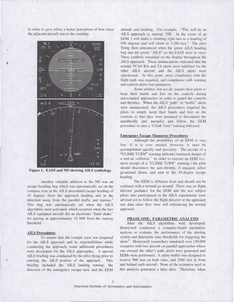
in order to g ive pilots a better perception of how clo e the adjacent aircra ft was to the ownship.
Figure 1. EADI and ND showing AILS symbology
Ano ther va luable additi on to the ND was an escape heading bug which was automaticall y set on the compass rose at the AILS procedural escape heading of 45 degrees from the approach heading and in the direction away from the para lle l traffic and runway.4 Thi bug was automatica lly set when the AILS algorithms were acti vated, which occ urred when the two AILS equipped aircraft did an e lectronic "hand shake" for pairing at approx imate ly 10 NM from the runway threshold .
AILS Procedures To ensure that the cockpit c rew was prepared
for the AILS approach and its responsibilities while conducting the approach , some additional procedure were deve loped fo r the AILS approaches. A specia l AILS briefin g was conducted by the pilot fl ying prior to e ntering the AILS porti on of the approach . This briefing included the AILS landing runway, the directi on of the emergency escape turn , and the EEM
3
altitude and heading. For example, "Thi s will be an AILS approach to run way 3SR. In the event of an EEM, I will make a climbing right turn to a head ing of 036 degrees and will c limb to 3,200 feet. " The pilot fl ying then announced whe n the green AILS heading bug and the green "AILS" on the EAD! were in view. These symbols rema ined on the di spl ay th roughout the AILS approach. These annunciati ons indicated that the normal TCAS RA and TA a lerts were inhi bited fo r the other AILS aircraft and the AILS alerts were operati onal. At thi po int, tric t compliance with the night path wa required , and compliance with warning and cauti on alert was mandatory.
Some a irlines. but not all , require the ir pilots to keep the ir hands and feet on the contro ls du ring autocoupled approaches in order to guard the contro ls and throttles. When the AILS "path" or "traffic" alerts were annunc iated , the AILS procedures required the pilot to imply keep their hand and feel on the controls so that they were prepared to disconnect the aulothroltl e and autopilot and foll ow the EEM procedure in case a "Climb T urn" warn ing fo llowed .
Emergencv Escape Maneuver Procedures Although the probability o f an EEM is very
low, if it is ever needed, however, it musl be accompli shed quickl y and precisely. T he receipt of a "CLIMB T URN" warning indicates imminent danger of a mid-a ir co lli sion.' In order to execute an EEM (i.e. , upon rece ipt of a "CLIMB TURN" warning,) the pilot should di sconnect the auto-throttle, if engaged, e lect go-around thru t, and turn to the 4S-degree escape heading.
The EEM is differe nt from and should not be confused with a normal go-around . There was no fli ght direcLOr guidance for the EEM and the test subject pilots who partic ipated in the AILS experiment were ad vised not to fo llow the fli ght direc tor or the approach raw data s ince they were still referenc ing the normal approach.
PHASE ONE: PARAMETRIC ANALYSIS After the AILS algorithms were developed,
Honeywe ll conducted a computer-based parametric analysis to eva luate the performance o f the alerting system and determine time thresho lds fo r triggering the alerts6
. Honeywe ll researcher s imulated over 150,000 scenario with two aircraft on parallel approaches where one crossed the other's path , alert were generated and EEMs were performed . A afety buffer was des igned to reserve 900 feet on both s ides, and 2500 fee t in fro nt and behind each aircraft. None of the scenari os used in
thi s analysis generated a false alert. There fore, when
American Institute of Aeronautics and Astronautics
~~---------------------
the intruderfi)llowed a "'normal" trajectory no alerts
were issued, and when the intruder intruded, the
appropriate alerts were issued.
Honeywell determined alert probabilities including
the probability of a successful alert, the probability of
an unnecessary/nuisance alert (different from a false
alert), and the probability of a collision given an alert.
Also defined by this parametric analysis was the
average miss distance" after an alert to measure how well
the alerting system kept the aircraft separated. These
values, along with findings from previous AILS studies
provided a baseline for the 1999 AILS simulator
study." s'
PHASE TWO: SIMULATION STUDY
The goal o1" the simulator phase of the study was to
validate through experimentation that a pilot's response
to an AILS alert was not affected by operational
variations such as the flight control mode used by the
pilot during the approach, the runway separation or the
geometry of the intruder's path. The experiment was
designed with two independent variables, runway
separation (2,5(X) and 3.400 feet) and flight control
mode (autocoupled and manual), and three dependent
measures, reaction time, miss distance (distance of
closest encounter) and subjective workload. The
subjects were required to l]y the EEM in the manual
mode.
Runway Spacing
Mode 2500 ft
Aulo X
Manual X
34OO fi
_ccna.l-iOS
2 3 4 5 6 I 2 3 4 5 6
X X X X X X X+X X X X
X X] X X .X X X X X X X
Table 2. AILS Run Matrix
The experiment was a full factorial experiment with
randomized blocks. The blocks were by both runway
spacing and control mode. To counteract learning, each
of the six encounter scenarios was masked to look
different to the subjects while preserving the
characteristic o1"the geometry.
Methods and Procedures
The subject pool consisted of 16 Boeing 757 type
rated pilots currently employed by commercial airlines.
A random mix of captains and first officers participated.
The subjects were trained individually and a training
script was used to achieve consistency. The subjects
were given a 50-minute classroom briefing on how to
interpret and respond to the AILS alerts, then a hands-
on session was conducted in the NASA Integrated
Flight Deck (IFD) simulator. The IFD is a fixed-based
simulator, which closely replicates the B-757 cockpit.
At the end of the classroom briefing, a simple quiz was
given to determine how much the subjects understood
about AILS and its procedures. Deliciencies evident
through a less-than-perfect score were corrected before
the st, bject moved on to the simulator-flying phase of
the experiment. As part of the simulator training, the
pilots were given the opportunity to fly several AILS
approaches. The first time was for familiarization (no
alerts were issued.) During the second approach, they
were exposed to a wind shear alert. Their performance
during this run served as a baseline indicating how they
performed in an emergency situation that was similar to
one that would trigger an AILS alert. The remaining
runs emphasized how the EEM should be executed as
well as reintbrcing the meaning of the AILS alerts.
One day after the subjects were trained, they
returned tbr the data collection phase of the experiment.
Each pilot flew the simulator from the lefl scat
accompanied by a research first officer in the right scat.
The paired aircraft, the intruder, was a simulated AILS-
equipped aircraft. Each run began with both aircraft on
the final approach approximately 14 miles from the
runway threshold. The subjects were expected to
approach the runway as they normally would for
landing, conforming to normal instructions from the
ATC unless an alert was issued. _° Each subjectcompleted 24 runs which included 20 runs where the
parallel traffic turned off-course toward the test
subject's aircraft. These intrusion scenarios therefore
represented a worse case situation where the intruding
aircraft failed to respond to its alerts and subsequently
caused the ownship to execute the EEM. jlk_ The six
intrusion scenarios were:
(1) intruder faster than ownship and passing ahead
(2) intruder faster than ownship passing behind
(3) intruder faster than ownship on a collision path
(4) intruder slower than ownship and passing ahead
(5) intruder slower than ownship and passing behind
(6) intruder slower than ownship on a collision path
4
American Institute of Aeronautics and Astronautics
The pilots' perceived workload was measured
by administering the NASA Task Load Index (TLX)
survey each time they changed flight control modes and
at the end of the experiment. A structured questionnaire
was also given at the end of the experiment.
PHASE THREE: FLIGHT TEST
The primary purpose of the flight experiment was
to validate the experimental data findings obtained inthe simulator. To this end, a subset of the simulator
study runs was performed in flight. The flight test was
conducted at NASA Wallops Flight Facility (WFF)
using the NASA B-757 as the ownship and the
Honeywell G-IV as the intruder. The six pilot test
subjects who participated in the flight test were B-757
type-rated captains who were selected from the 16
simulator subject population. Each subject flew a total
o1"6 intrusion scenarios in the flight test, a subset of the
number they had flown in the simulator. The intrusionscenarios were:
( 1 ) intruder slower than ownship and passing behind
(2) intruder faster than ownship passing behind
(3) intruder faster than ownship on a collision path
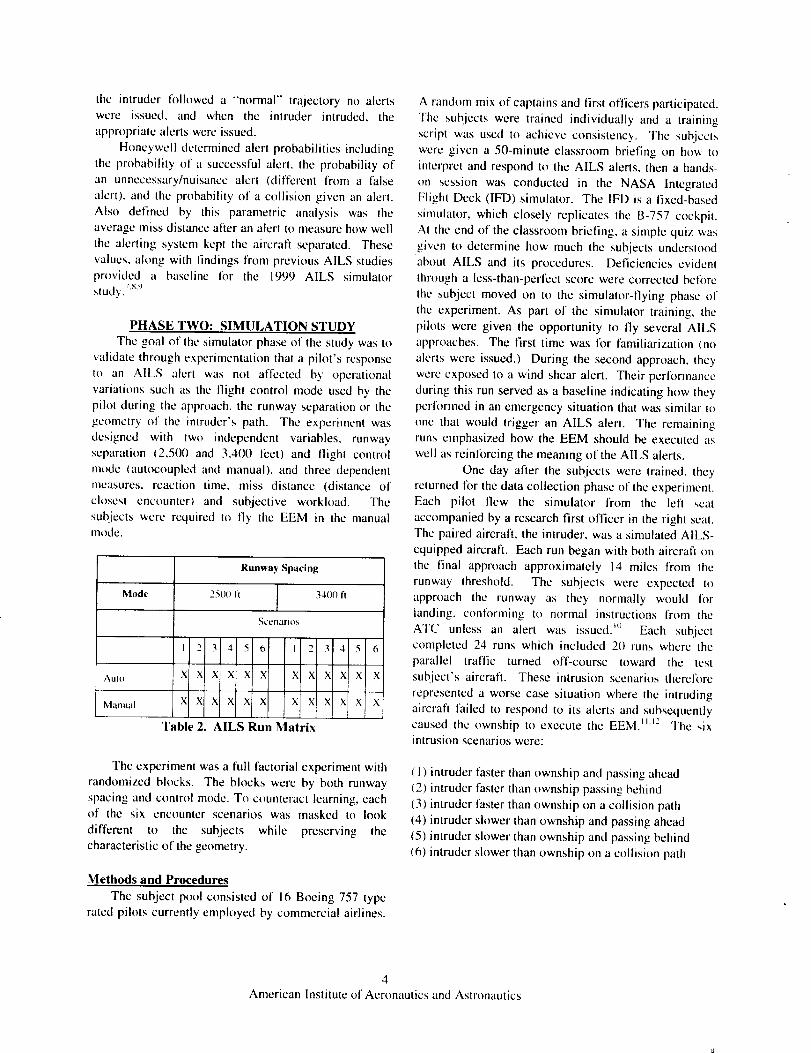
Figure 2 shows one of the flight trajectories flown
by ownship and the intruder. Note the points at which
the caution and warning alerts were triggered and the
predicted closest point of approach (CPA).
Runway 35 at WFF was selected based on the
desirability to operate south of the airport. In addition
to the existing Runway 35, two additional "pseudo"
parallel runways were created, one representing the
2.500 feet lateral separation, the other 3,400 feet. The
aircraft were "staged" for each approach to achieve the
desired initialization point of the encounter and at the
desired speed and to closely replicate the intrusion
scenarios of the simulator study.
DGPS course guidance was provided by
Honeywell's version of a GPS Landing System, a
Satellite Landing System (SLS-2000), which uses
Differential GPS for guidance. Each final approach
course was ofl_et 2 degrees outboard from the extended
runway centerline to alleviate the problem of
overlapping azimuth courses. The extended centerlineof the runway and the final approach course intersected
0.44nm (2,676 It) from the runway threshold. The glide
slope was 3 degrees for all approaches.
-2.q
-2.1
-3.1
-3.!
-4.q
-4._
-5.1
-5J
-6.1
-6._
Intruder Position relative to Ownship
).o 0.5 I.o
East Dist., nm
_ 1. Caution
" _ Warning
t _ Predicted CPA
..... _ /1"_- l- "I " ] "
Figure 2. Intruder Position relative to Ownship
SUMMARY OF SIMULATION AND FLIGHTRESULTS
Statistical analyses were done using the
MINITAB TM version 13 statistics package. Multivariate
analysis of variance (MANOVA) was used to test the
effect of the factors, flight control mode, runway
separation, scenario, aircraft speeds, and interactioneffects of these combined factors on both the reaction
time and miss distance. T-tests were conducted to lcsl
that the mean reaction time would be less than 2
seconds (a design goal) and that the mean miss distance
would be equal to 1,200 ft (also a design goal). Inaddition, a Z- lest of the variance was conducted for amiss distance of 1,200+500 ft. _3 These tests not only
considered the individual responses, but also thecorrelation and co-variances between and within the
factors and responses. Although the flight data set was
not meant to be a statistically valid sample, the trends
acquired in flight tollowed those of the simulator and
therefore met the intent of validating the findings fromthe simulator.
5American Institute of Aeronautics and Astronautics
Source
Control mode
Runway separation
Error
Total
Source
Control mode
Runway separation
Error
Total
[ Degrees ol Sequent,al sum[ Adjusted sumfreedom / of squares of squares
i
1 3.919 3.9088 3.9088
[ I O.1594 O. 1594 0.1594
313 60.9515 60.9515 0.1947
315 65.0299Table 3a. MANOVA of Simulator Reaction Times
Adjusted mean
square
F
20.07
0.82
i
P-value
0.0000*
0.366
" 7", . . [ .Degrees ol Sequent,al sum Adlusted sum ]Adjusted mean= F P-value
freedom i of squares of squares " square i
/ !I
1 237938 241913 241913 1.05 0.306
I 413047 I 413047 413047 1.79 0.18 I
313 72073323 72073323 i 230266
315 72724308
Table 3b. MANOVA of Simulator Miss Distances
Test of Reaction Time Hypotheses
The statistical analyses presented here were
based on the assumption that the scenarios had no effect
on the reaction time and miss distance and that only the
c[fccts of llight control mode and runway separations
were being investigated. The null hypotheses, Ho, and
the alternate hypotheses, H, were tested for each case.
runway separations, on the other hand, did not have a
significant effect on the recorded reaction times.
Test of Miss Distance Hypotheses
To investigate whether the miss distances wcrc
affected by the llight control mode or the runway
separation, null hypotheses H,,._and H,,4 and alternate
hypotheses Ha3 and H,4 were tested.
H,,I: Mean RT_ = Mean RTM
Hoe: Mean RT> = Mean RT34H,a: Mean RTA _ Mean RTM
H_,_: Mean RT> :1:Mean RT34
Ho_: Mean MDa = Mean MDM
Ho4: Mean MD> = Mean MD34
H,,_: Mean MD._, Mean MDM
Ha4: Mean MD,_ _: Mean MD34
As shown in the MANOVA Table 3a above,
the first null hypothesis was rejected with a P-value of
0.0(X)0. This means that based on the experimental
results, at a signiticance level of ot = 0.05, there was asignificant difference between the mean reaction time in
the autopilot mode (RTA) and the mean reaction time in
the manual mode (RTM). We failed to reject the secondnull hypothesis. This means that based on the
experimental results, there was not a significantdifference between the mean reaction time when
approaching runways that were 2.500 feet apart (RT2s)and the mean reaction time when approaching runways
that were 3,400 feet apart (RT_4).
In other words, the flight control mode indeedhad a statistically significant effect on the reaction time.
As explained later in the questionnaire section, the test
subiects did not validate this fact, possibly because thedifference was too small tor human perception. The
Based on a significance level of o_ = 0.05, we
failed to reject both the third and fourth null hypotheses.The results of the MANOVA are shown in Table 3b.
This means that based on the experimental results, there
is neither a significant difference between the miss
distance while tlying an autopilot approach thenswitching to flying the EEM in the manual mode (MDA)
versus flying the entire approach in the manual mode(MDM). There was not a significant difference between
the mean miss distance when the runways were 2.500
feet apart (MDes) versus the mean miss distance when
the runways were 3,400 feet apart (MD34).
Subjective Ouestionnaire
The questionnaire was administered after the
pilots completed all runs. It consisted of 12 questions
addressing issues such as the AILS operational
6
American Institute of Aeronautics and Astronautics
feasibility,theEEMandotherprocedures,thedisplaysandalerts,andtheflight controlmodesusedwhileflyingtheAILS approaches.Thesequestionsweredesignedto serveas validationfor thequantitativeresponses.
Approximately44%of"testsubjectpilotsdidnotpreferaparticularflightcontrolmodefl)r theAILSapproach,butof thosewhohada preferencemorepreferredtheautopilotmode.A totalof 55%of therespondentsdid not thinktheautopilotslowedtheirresponseto theEEM. However,accordingto actualreactiontime data from the simulator,subjectsrespondedslowerwhenflyinganautopilot approach.
The difference was 0.3 seconds, which proved to be too
low Ibr human perception.
A confirmatory factor analysis was performed
on the subjective questionnaire to verify its
effectiveness in addressing the different factors. Factor
analysis was based on the correlation between the
recorded responses to the questions. In general, most of
the responses to the questionnaire were in favor of
AILS. Questions about alerts and EEM factored out as
expected (i.e., validated the quantitative results obtainedfrom the simulator). Correlation coefficients between
the question addressing the AILS operational feasibility
and the average recorded values of the reaction time in
the auto-coupled mode resulted in a positive correlationof 0.41 and miss distance in manual mode resulted in a
negative correlation of- 0.52 which implied that
whenever the subjects stated that AILS is "very
practical" they scored larger reaction times, and smaller
miss distances. This discrepancy may be attributed to
the way the questions were posed to the pilot test
subjects.
DEMONSTRATION FLIGHTS
As a way of testing the AILS concept in an
active airport environment where parallel runway
operations are conducted, the MSP airport was chosen
fi_r the AILS demonstration flights. Of the threeintrusion scenarios that were tested at WFF, the
scenario where the intruder was slower than the
ownship and passing behind was flown to demonstrate
to industry and government that two aircraft on parallel
runways at 3,400 feet apart can safely perform an
approach to landing in IMC.
Unlike the isolated airspace at Wallops, MSPis encapsulated by Class B airspace, u The air traffic
controllers at MSP provided ATC services as well as
staging assistance to the AILS aircraft. Due to the
precision required in the staging process, assistance wasprovided from a ground facility. The MSP controllers
assisted in staging the aircrafl by providing heading and
speed guidance, NASA pilots in the B-757 and
Honeywell pilots in the G-IV flew the demonstrationruns.
CONCLUSION
The AILS system was successfully developed.
tested in simulation and flight, and demonstrated in an
operational environment at MSP. Each phase of this
multi-phased project brought researchers closer to
realizing the feasibility of the AILS concept. Important
questions regarding an onboard separation capabilitywere answered in the research. The robustness of the
study was enhanced by taking the users into
consideration and accounting for their performance
while operating the system.
It is now known that pilots will respond to the
AILS alerts in approximately 1 second whether the
distance between the runways is 3,400 feet or 2,500
feet. Although statistical variations (0.3 seconds) were
seen in mean pilot response time when the approach
was flown in the autopilot mode versus when flown in
the manual mode, the difference was not operationally
significant.The distance the aircraft closed on each other
before they broke out of the approach was not affi:cted
by flight control mode or runway separation. This is
because the AILS algorithms were modeled on timethresholds that were built into the system. 15'n_
Specifically, the mean miss distance found in thesimulator was 2,236 feet with a standard deviation of
479 feet. In flight, the mean miss distance was 1,860
feet, within the range of the value obtained in thesimulator.
Pilot acceptability of the A1LS concept was
outstanding. They appreciated the clarity of the alerts
and the simplicity of the operational procedures. By
using existing guidance, navigation and controltechnologies, AILS has demonstrated the feasibility to
perform instrument approaches to closely spaced
parallel runways.
ACKNOWLEDGMENTS
The NASA/Honeywell partnership enabled the
successful completion of this study. With respect and
gratitude we offer tribute lo the pioneers of the AILS
concept, Leonard Credeur, Charlie Scanlon, Marvin
Waller, Gary Lohr and Bill Capron. Also deserving ofcredit are the other members of the NASA LaRC AILS
development team, Terence Abbott, Phil Brown, and
Laura Rine, as well as the contractor counterparts, from
Lockheed-Martin, Jake Barry, Dan Burdette and Frank
McGee: retired United Airline Captains. William
Gifford and Dave Simmon: and from Adsystech, Inc.,
7
American Institute of Aeronautics and Astronautics
ThomasDoyle.Much appreciation is also extended to
Honeywell, specifically, Bill Corwin, Dave Maahs, Paul
Samanant, Mike Jackson, Scott Snyder and Christine
Haissig for taking an interest in the AILS concept and
working to make this research a success. Many otherpersons whose names are not mentioned here have
contributed significantly, and the authors express theirsincerest thanks.
REFERENCES
I. Federal Aviation Administration, Precision
Runway Monitor Demonstration Report. Document
(D()T/FAA/RD-9 I/5). Washington, DC: U.S.
Government Printing Office, 1991.
2. Haissig. C. M., Corwin,B., Jackson, M.,
"'Designing an Airborne Alerting System for
Closcly Spaced Parallel Approaches," Paper
AIAA-99-3986. AIAA Guidance, Navigation andControl Confercncc, Portland, OG, 2000
3. Hemm. R.. & Shappiro, G., Airborne h_'ormatio,
,[_Jr Lateral Spacing (AILS) Benefit Estimate.NS906S 1+ 1999.
4. Rine, L., Abbott, T.. Lohr, G., Elliott, D., Waller,
M. C.. Perry, R. B., The Flight Deck Perspective _/the NASA Langley AILS Concept. NASA/TM-
2000-209841. January 2(,u00.5. Winder, L., & Kuchar, J. K., "Evaluation of
Vertical Collision Avoidance Maneuvers For
Parallel Approach." Paper AIAA-98-4242. AIAA
Guidance, Navigation and Control Conference,
Boston, MA, January 1998.
6. Jackson, M., Samanant, P., & Haissig, C., "'Designand Analysis of Airborne Alerting Algorithms Ibr
Closely Spaced Parallel Approaches," Paper
AIAA-2000-4359. AIAA Guidance, Navigationand Control Conference, Denver, CO August 20(X).
7. Waller, M. & Scanlon, C. (Eds). Proceedings (_[
the NASA Workshop on Flight Deck Centered
Parallel Runway Approaches in Instrument
Meteorological Conditions, NASA Conference
Publication I019 I, Hampton, VA December 1996.
8. Waller, M., & Scanlon, C. Simulation Study of
1MC Approaches to Dual Parallel Runways Spaced
3400 and 2500 Feet Apart Using Flight Deck
Centered Technology, NASA/TM-1999-208743,1999.
9. Waller, M., & Scanlon, C., A Simulation Study of
IMC Approaches to Dual Parallel Runways Spaced
1700 attd 1200 Feet Apart Using Flight Deck
Centered Technology (unpublished).
10. Waller, M., Doyle, T., & McGee, F., Analysis of
the Role of ATC in the AILS Concept, NASA/TM-2000-21 (X)9 I. 2000.
11. Ebrahimi, Y. S., Parallel Runway Requirement
Analysis Study. Volume 1-The Analysis. NASACR- 191549, 1993a.
12. Ebrahimi, Y. S., Parallel Runway RequirementAnalysis Study, Volume 2-Simulation Manual.NASA CR-191549, 1993b.
13. Abbott, T., and Elliott, D., A Simulator Evaluation
of the Airborne htformation Jbr Lateral Spacing
Concept. NASA/TP (in press).
14. Doyle, T., & McGcc, F, Air Traffic and
Operational Data for Selected U.S. Airports with
Parallel Runways, 1998.
15. Kuchar. J. K., and Carpenter+ B. D. Airborne
Collision Alerting Logic for Closcly-Spaccd
Parallel Approach, Air Traffic Control Quarterly,Vol. 5, No. 2, 1997.
16. Carpenter, B., & J. Kuchar, "Probability-Based
Collision Alerting Logic for Closely-SpacedParallel Approach," Paper AIAA-97-0222. AIAA
Aerospace Sciences Mccting and Exhibit+ Rcno,
NV. January 1997.
The authors may be contacted via electronic mail
at: [email protected] (Dawn EIliott) and
raleigh.b.pero'@larc.nasa.gov (R. Brad Pero_ ).
8
American Institute of Aeronautics and Astronautics


![COELI DÈSUPER CopioneUnificato.pdf · 4 Nitida stella [1:00] - (Anunziata) Anonimo afff32 F =150 3 jj jj jj eii jj jj jj jj i ji j i ji j i ji j eiizz bfff32 j j j i j j j j i j](https://img.pdfslide.us/doc/110x75/5fde88e826cc8964f53d1e56/coeli-d-copioneunificatopdf-4-nitida-stella-100-anunziata-anonimo-afff32.jpg)


![wstsm.drmeganargo.net · Web viewThe Sun. Image credit: NASA/SDO (AIA) [Public domain] hot. yellow](https://img.pdfslide.us/doc/110x75/5e0408db9f934864981da37c/wstsm-web-viewthe-sun-image-credit-nasasdo-aia-public-domain-hot-yellow.jpg)