Embed Size (px)
Citation preview

IPhone 805-482-6913 Fax 805-482-9224
JIMS® NEW PRODUCTS
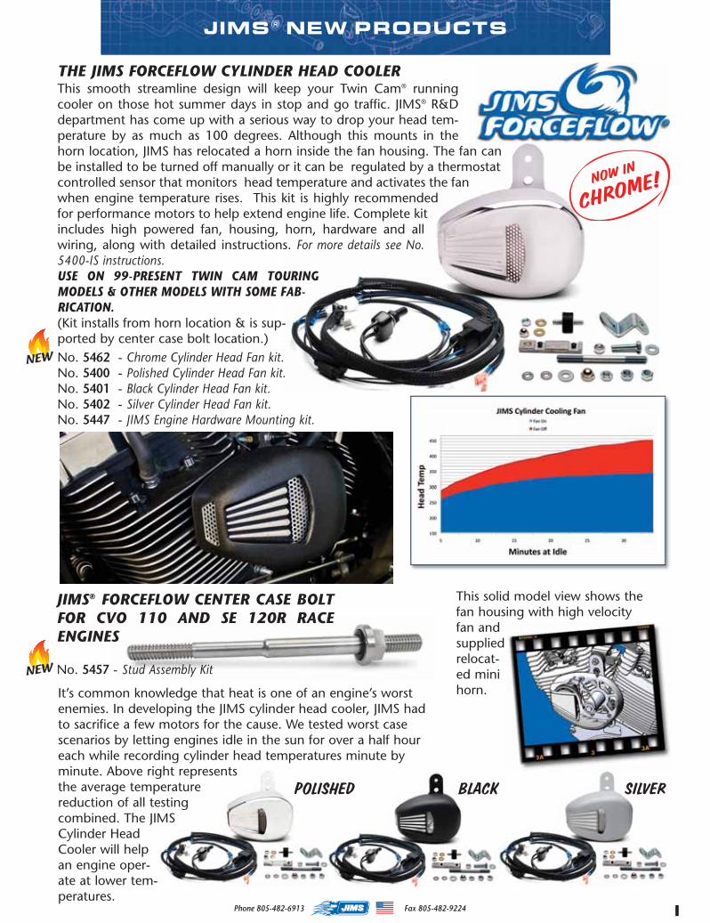
THE JIMS FORCEFLOW CYLINDER HEAD COOLERThis smooth streamline design will keep your Twin Cam® runningcooler on those hot summer days in stop and go traffic. JIMS® R&Ddepartment has come up with a serious way to drop your head tem-perature by as much as 100 degrees. Although this mounts in thehorn location, JIMS has relocated a horn inside the fan housing. The fan canbe installed to be turned off manually or it can be regulated by a thermostatcontrolled sensor that monitors head temperature and activates the fanwhen engine temperature rises. This kit is highly recommendedfor performance motors to help extend engine life. Complete kitincludes high powered fan, housing, horn, hardware and allwiring, along with detailed instructions. For more details see No.5400-IS instructions.USE ON 99-PRESENT TWIN CAM TOURINGMODELS & OTHER MODELS WITH SOME FAB-RICATION.(Kit installs from horn location & is sup-ported by center case bolt location.)No. 5462 - Chrome Cylinder Head Fan kit.No. 5400 - Polished Cylinder Head Fan kit.No. 5401 - Black Cylinder Head Fan kit.No. 5402 - Silver Cylinder Head Fan kit.No. 5447 - JIMS Engine Hardware Mounting kit.
It’s common knowledge that heat is one of an engine’s worstenemies. In developing the JIMS cylinder head cooler, JIMS hadto sacrifice a few motors for the cause. We tested worst casescenarios by letting engines idle in the sun for over a half houreach while recording cylinder head temperatures minute byminute. Above right representsthe average temperaturereduction of all testingcombined. The JIMSCylinder HeadCooler will helpan engine oper-ate at lower tem-peratures.
This solid model view shows thefan housing with high velocityfan andsuppliedrelocat-ed minihorn.
JIMS® FORCEFLOW CENTER CASE BOLTFOR CVO 110 AND SE 120R RACEENGINES
No. 5457 - Stud Assembly Kit
POLISHED BLACK SILVER
NOWIN
CHROME!
MASTER 2014 CAT INSERT proof.qxp:Layout 1 10/30/14 7:58 AM Page 1
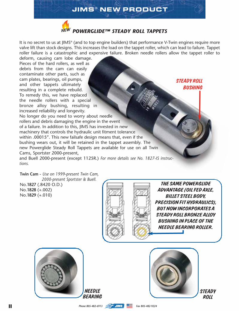
POWERGLIDE™ STEADY ROLL TAPPETS
It is no secret to us at JIMS® (and to top engine builders) that performance V-Twin engines require morevalve lift than stock designs. This increases the load on the tappet roller, which can lead to failure. Tappetroller failure is a catastrophic and expensive failure. Broken needle rollers allow the tappet roller todeform, causing cam lobe damage.Pieces of the hard rollers, as well asdebris from the cam can easilycontaminate other parts, such ascam plates, bearings, oil pumps,and other tappets ultimatelyresulting in a complete rebuild.To remedy this, we have replacedthe needle rollers with a specialbronze alloy bushing, resulting inincreased reliability and longevity.No longer do you need to worry about needlerollers and debris damaging the engine in the eventof a failure. In addition to this, JIMS has invested in newmachinery that controls the hydraulic unit fitment tolerancewithin .00015”. This new failsafe design means that, even if thebushing wears out, it will be retained in the tappet assembly. Thenew Powerglide Steady Roll Tappets are available for use on all TwinCams, Sportster 2000-present,and Buell 2000-present (except 1125R.) For more details see No. 1827-IS instruc-tions.
Twin Cam - Use on 1999-present Twin Cam,2000-present Sportster & Buell.
No.1827 (.8420 O.D.)No.1828 (+.002)No.1829 (+.010)
II Phone 805-482-6913 Fax 805-482-9224
JIMS® NEW PRODUCT
THE SAMEPOWERGLIDEADVANTAGE (OIL FEDAXLE,BILLET STEEL BODY,
PRECISION FIT HYDRAULICS),BUTNOW INCORPORATESASTEADYROLL BRONZEALLOYBUSHING IN PLACEOF THENEEDLEBEARINGROLLER.
NEEDLEBEARING
STEADYROLL
STEADYROLLBUSHING
MASTER 2014 CAT INSERT proof.qxp:Layout 1 10/30/14 7:59 AM Page 2
JIMS® NEW PRODUCT
Phone 805-482-6913 Fax 805-482-9224
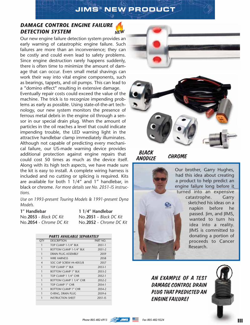
DAMAGE CONTROL ENGINE FAILUREDETECTION SYSTEMOur new engine failure detection system provides anearly warning of catastrophic engine failure. Suchfailures are more than an inconvenience; they canbe costly and could even lead to safety problems.Since engine destruction rarely happens suddenly,there is often time to minimize the amount of dam-age that can occur. Even small metal shavings canwork their way into vital engine components, suchas bearings, tappets, and oil pumps. This can lead toa “domino effect” resulting in extensive damage.Eventually repair costs could exceed the value of themachine. The trick is to recognize impending prob-lems as early as possible. Using state-of-the-art tech-nology, our new system monitors the presence offerrous metal debris in the engine oil through a sen-sor in our special drain plug. When the amount ofparticles in the oil reaches a level that could indicateimpending trouble, the LED warning light in theattractive handlebar clamp immediately illuminates.Although not capable of predicting every mechani-cal failure, our US-made warning device providesadditional protection against engine repairs thatcould cost 50 times as much as the device itself.Along with its high tech aspects, we have made surethe kit is easy to install. A complete wiring harness isincluded and no cutting or splicing is required. Kitsare available for both 1 1/4” and 1” handlebar, inblack or chrome. For more details see No. 2051-IS instruc-tions.Use on 1993-present Touring Models & 1991-present DynaModels.1” HandlebarNo.2053 - Black DC KitNo.2054 - Chrome DC Kit
Our brother, Garry Hughes,had this idea about creatinga product to help predict anengine failure long before itturned into an expensive
catastrophe. Garrysketched his ideas on anapkin before hepassed. Jim, and JIMS,wanted to turn hisidea into a reality.JIMS is committed todonating a portion ofproceeds to CancerResearch.
AN EXAMPLE OF A TESTDAMAGECONTROL DRAINPLUG THAT PREDICTED ANENGINE FAILURE!
BLACKANODIZE CHROME
III
1 1/4” HandlebarNo.2051 - Black DC KitNo.2052 - Chrome DC Kit
PARTS AVAILABLE SEPARATELYQTY DESCRIPTION PART NO.
1 TOP CLAMP 1-1/4” BLK 2051-1
1 BOTTOM CLAMP 1-1/4” BLK 2051-2
1 DRAIN PLUG ASSEMBLY 2059
1 WIRE HARNESS 2058
4 SOC CAP SCREW #4-40X3/8 2057
1 TOP CLAMP 1” BLK 2053-1
1 BOTTOM CLAMP 1” BLK 2053-2
1 TOP CLAMP 1 1/4” CHR 2052-1
1 BOTTOM CLAMP 1 1/4” CHR 2052-2
1 TOP CLAMP 1” CHR 2054-1
1 BOTTOM CLAMP 1” CHR 2054-2
1 O-RING, DRAIN PLUG 2059-6
1 INSTRUCTION SHEET 2051-IS
MASTER 2014 CAT INSERT proof.qxp:Layout 1 10/30/14 7:59 AM Page 3
Phone 805-482-6913 Fax 805-482-9224IV
JIMS® NEW PRODUCT
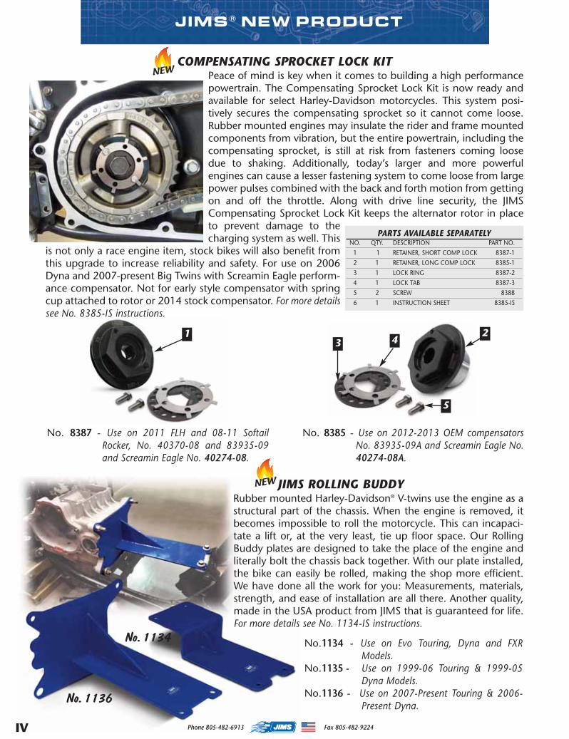
COMPENSATING SPROCKET LOCK KITPeace of mind is key when it comes to building a high performancepowertrain. The Compensating Sprocket Lock Kit is now ready andavailable for select Harley-Davidson motorcycles. This system posi-tively secures the compensating sprocket so it cannot come loose.Rubber mounted engines may insulate the rider and frame mountedcomponents from vibration, but the entire powertrain, including thecompensating sprocket, is still at risk from fasteners coming loosedue to shaking. Additionally, today’s larger and more powerfulengines can cause a lesser fastening system to come loose from largepower pulses combined with the back and forth motion from gettingon and off the throttle. Along with drive line security, the JIMSCompensating Sprocket Lock Kit keeps the alternator rotor in placeto prevent damage to thecharging system as well. This
is not only a race engine item, stock bikes will also benefit fromthis upgrade to increase reliability and safety. For use on 2006Dyna and 2007-present Big Twins with Screamin Eagle perform-ance compensator. Not for early style compensator with springcup attached to rotor or 2014 stock compensator. For more detailssee No. 8385-IS instructions.
No. 8387 - Use on 2011 FLH and 08-11 SoftailRocker, No. 40370-08 and 83935-09and Screamin Eagle No. 40274-08.
No. 8385 - Use on 2012-2013 OEM compensatorsNo. 83935-09A and Screamin Eagle No.40274-08A.
PARTS AVAILABLE SEPARATELYNO. QTY. DESCRIPTION PART NO.
1 1 RETAINER, SHORT COMP LOCK 8387-1
2 1 RETAINER, LONG COMP LOCK 8385-1
3 1 LOCK RING 8387-2
4 1 LOCK TAB 8387-3
5 2 SCREW 8388
6 1 INSTRUCTION SHEET 8385-IS
1 23 4
5
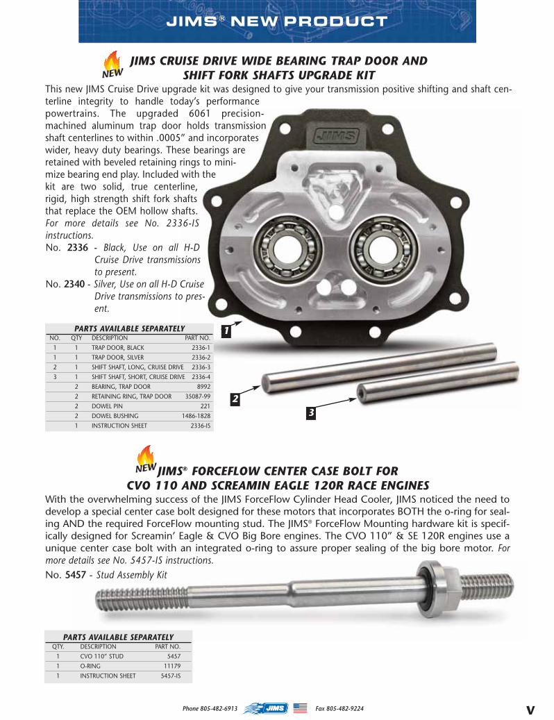
JIMS ROLLING BUDDYRubber mounted Harley-Davidson® V-twins use the engine as astructural part of the chassis. When the engine is removed, itbecomes impossible to roll the motorcycle. This can incapaci-tate a lift or, at the very least, tie up floor space. Our RollingBuddy plates are designed to take the place of the engine andliterally bolt the chassis back together. With our plate installed,the bike can easily be rolled, making the shop more efficient.We have done all the work for you: Measurements, materials,strength, and ease of installation are all there. Another quality,made in the USA product from JIMS that is guaranteed for life.For more details see No. 1134-IS instructions.
No.1134 - Use on Evo Touring, Dyna and FXRModels.
No.1135 - Use on 1999-06 Touring & 1999-05Dyna Models.
No.1136 - Use on 2007-Present Touring & 2006-Present Dyna.
No. 1136
No. 1134
MASTER 2014 CAT INSERT proof.qxp:Layout 1 10/30/14 7:59 AM Page 4
VPhone 805-482-6913 Fax 805-482-9224
JIMS® NEW PRODUCT
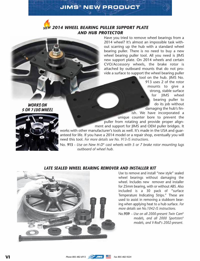
JIMS CRUISE DRIVE WIDE BEARING TRAP DOOR ANDSHIFT FORK SHAFTS UPGRADE KIT
This new JIMS Cruise Drive upgrade kit was designed to give your transmission positive shifting and shaft cen-terline integrity to handle today’s performancepowertrains. The upgraded 6061 precision-machined aluminum trap door holds transmissionshaft centerlines to within .0005” and incorporateswider, heavy duty bearings. These bearings areretained with beveled retaining rings to mini-mize bearing end play. Included with thekit are two solid, true centerline,rigid, high strength shift fork shaftsthat replace the OEM hollow shafts.For more details see No. 2336-ISinstructions.No. 2336 - Black, Use on all H-D
Cruise Drive transmissionsto present.
No. 2340 - Silver, Use on all H-D CruiseDrive transmissions to pres-ent.
23
1
JIMS® FORCEFLOW CENTER CASE BOLT FORCVO 110 AND SCREAMIN EAGLE 120R RACE ENGINES
With the overwhelming success of the JIMS ForceFlow Cylinder Head Cooler, JIMS noticed the need todevelop a special center case bolt designed for these motors that incorporates BOTH the o-ring for seal-ing AND the required ForceFlow mounting stud. The JIMS® ForceFlow Mounting hardware kit is specif-ically designed for Screamin’ Eagle & CVO Big Bore engines. The CVO 110” & SE 120R engines use aunique center case bolt with an integrated o-ring to assure proper sealing of the big bore motor. Formore details see No. 5457-IS instructions.No. 5457 - Stud Assembly Kit
PARTS AVAILABLE SEPARATELYQTY. DESCRIPTION PART NO.
1 CVO 110” STUD 5457
1 O-RING 11179
1 INSTRUCTION SHEET 5457-IS
PARTS AVAILABLE SEPARATELYNO. QTY DESCRIPTION PART NO.
1 1 TRAP DOOR, BLACK 2336-1
1 1 TRAP DOOR, SILVER 2336-2
2 1 SHIFT SHAFT, LONG, CRUISE DRIVE 2336-3
3 1 SHIFT SHAFT, SHORT, CRUISE DRIVE 2336-4
2 BEARING, TRAP DOOR 8992
2 RETAINING RING, TRAP DOOR 35087-99
2 DOWEL PIN 221
2 DOWEL BUSHING 1486-1828
1 INSTRUCTION SHEET 2336-IS
MASTER 2014 CAT INSERT proof.qxp:Layout 1 10/30/14 7:59 AM Page 5
Phone 805-482-6913 Fax 805-482-9224
2014 WHEEL BEARING PULLER SUPPORT PLATEAND HUB PROTECTOR
Have you tried to remove wheel bearings from a2014 wheel? It’s almost an impossible task with-out scarring up the hub with a standard wheelbearing puller. There is no need to buy a newwheel bearing puller tool. All you need is JIMSnew support plate. On 2014 wheels and certainCVO/Accessory wheels, the brake rotor isattached by outboard mounts that do not pro-vide a surface to support the wheel bearing puller
tool on the hub. JIMS No.913 uses 2 of the rotormounts to give astrong, stable surfacefor JIMS wheelbearing puller todo its job without
damaging the hub’s fin-ish. We have incorporated a
unique counter bore to prevent thepuller from rotating and provide proper align-
ment and support for JIMS and OEM puller bridges. Itworks with other manufacturer’s tools as well. It’s made in the USA and guar-anteed for life. If you have a 2014 model or a repair shop, eventually you willneed this tool. For more details see No. 913-IS instructions.No. 913 - Use on New H-D® cast wheels with 5 or 7 brake rotor mounting lugs
outboard of wheel hub.
VI
JIMS® NEW PRODUCT
LATE SEALED WHEEL BEARING REMOVER AND INSTALLER KITUse to remove and install “new style” sealedwheel bearings without damaging thewheel. Includes new remover and installerfor 25mm bearing, with or without ABS. Alsoincluded is a 30 pack of “surfaceTemperature Indicating Strips.” These areused to assist in removing a stubborn bear-ing when applying heat to a hub surface. Formore details see No.1042-IS instructions.No.939 - Use on all 2000-present Twin Cam®
models, and all 2000 Sportsters®
models, and V-Rod®s 2002-present.
WORKSON5OR7 LUGWHEEL
MASTER 2014 CAT INSERT proof.qxp:Layout 1 10/30/14 7:59 AM Page 6
Phone 805-482-6913 Fax 805-482-9224 VII
JIMS® NEW PRODUCT
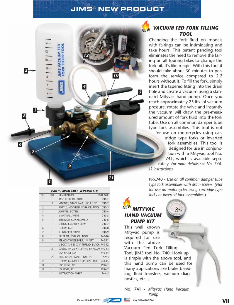
PARTS AVAILABLE SEPARATELYNO. QTY DESCRIPTION PART NO.
1 1 BASE, FORK OIL TOOL 740-1
3 MAGNET, GRADE N42, 1/2" X 1/8" 740-2
2 1 BOTTLE, MODIFIED, FORK OIL TOOL 740-3
3 1 ADAPTER, BOTTLE 740-4
4 1 3-WAY BALL VALVE 740-5
5 1 RESERVOIR CUP ASSEMBLY 740-6
1 O-RING 1.75" ID X .139" 740-7
6 1 ELBOW, 1/4" 740-8
7 1 "L" BRACKET, VALVE 740-9
8 1 FILLER TIP, FORK OIL TOOL 740-10
9 1 STRAIGHT HOSE BARB, 1/4 NPT 740-11
1 U-BOLT, 1/4-20 X 1" THREAD, BLACK 740-12
2 SCREW, 1/4-20 X 1/2" FHS, BK ALLOY 740-13
1 CAP, MODIFIED 740-14
2 NUT, 1/4-20 FLANGE, NYLON 5263
10 1 ELBOW, 1/4 NPT X 1/4" HOSE BARB 740-15
11 1 1/4" HOSE, 22" 1994-1
12 1 1/4 HOSE, 12" 1994-2
1 INSTRUCTION SHEET 740-IS
MITYVACHAND VACUUM
PUMP KITThis well knownMityvac pump isrequired for usewith the aboveVacuum Fed Fork FillingTool, JIMS tool No. 740. Hook upis simple with the above tool, andthis hand pump can be used formany applications like brake bleed-ing, fluid transfers, vacuum diag-nostics, etc...
No. 741 - Mityvac Hand VacuumPump
1
5
10
9
3
2
4
8
6
7
11
12
VACUUM FED FORK FILLINGTOOL
Changing the fork fluid on modelswith fairings can be intimidating andtake hours. This patent pending tooleliminates the need to remove the fair-ing on all touring bikes to change thefork oil. It’s like magic! With this tool itshould take about 30 minutes to per-form the service compared to 2.2hours without it. To fill the fork, simplyinsert the tapered fitting into the drainhole and create a vacuum using a stan-dard Mityvac hand pump. Once youreach approximately 25 lbs. of vacuumpressure, rotate the valve and instantlythe vacuum will draw the pre-meas-ured amount of fork fluid into the forktube. Use on all common damper tubetype fork assemblies. This tool is not
for use on motorcycles using car-tridge type forks or invertedfork assemblies. This tool isdesigned for use in conjunc-tion with a Mityvac tool No.741, which is available sepa-
rately. For more details see No. 740-IS instructions.
No.740 - Use on all common damper tubetype fork assemblies with drain screws. (Notfor use on motorcycles using cartridge typeforks or inverted fork assemblies.)
MASTER 2014 CAT INSERT proof.qxp:Layout 1 10/30/14 7:59 AM Page 7
Phone 805-482-6913 Fax 805-482-9224VIII
JIMS® NEW PRODUCT
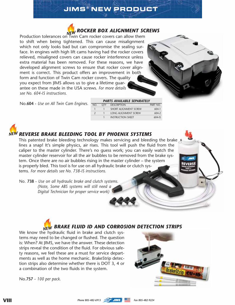
ROCKER BOX ALIGNMENT SCREWSProduction tolerances on Twin Cam rocker covers can allow themto shift when being tightened. This can cause misalignmentwhich not only looks bad but can compromise the sealing sur-face. In engines with high lift cams having had the rocker coversrelieved, misaligned covers can cause rocker interference unlessextra material has been removed. For these reasons, we havedeveloped alignment screws to ensure that rocker cover align-ment is correct. This product offers an improvement in bothform and function of Twin Cam rocker covers. The qualityyou expect from JIMS allows us to give a lifetime guar-antee on these made in the USA screws. For more detailssee No. 604-IS instructions.
No.604 - Use on All Twin Cam Engines.PARTS AVAILABLE SEPARATELY
NO. QTY DESCRIPTION PART NO.
1 1 SHORT ALIGNMENT SCREW 604-1
2 1 LONG ALIGNMENT SCREW 604-2
1 INSTRUCTION SHEET 604-IS
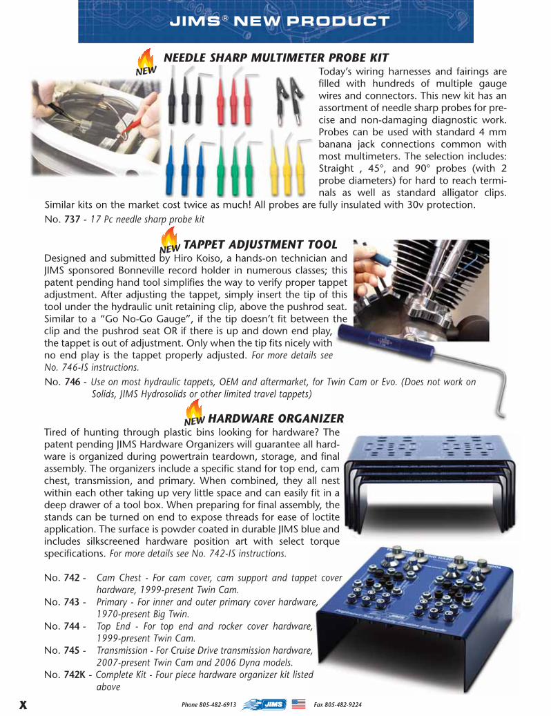
BRAKE FLUID ID AND CORROSION DETECTION STRIPSWe know the hydraulic fluid in brake and clutch sys-tems may need to be changed or flushed. The questionis: When? At JIMS, we have the answer. These detectionstrips reveal the condition of the fluid. For obvious safe-ty reasons, we feel these are a must for service depart-ments as well as the home mechanic. BrakeStrip detec-tion strips also determine whether there is DOT 3, 4 ora combination of the two fluids in the system.
No.757 - 100 per pack.
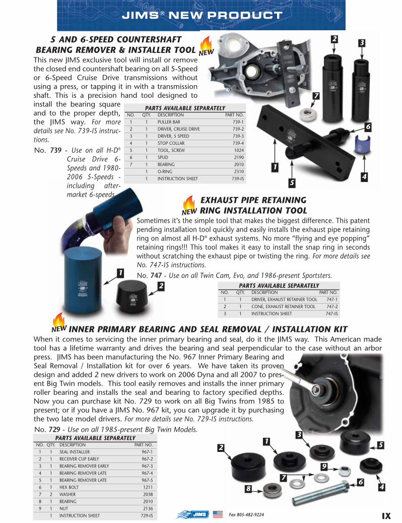
REVERSE BRAKE BLEEDING TOOL BY PHOENIX SYSTEMSThis patented brake bleeding technology makes servicing and bleeding the brakelines a snap! It’s simple physics, air rises. This tool will push the fluid from thecaliper to the master cylinder. There’s no guess work; you can easily watch themaster cylinder reservoir for all the air bubbles to be removed from the brake sys-tem. Once there are no air bubbles rising in the master cylinder – the systemis properly bled. This tool is for use on all hydraulic brake or clutch sys-tems. For more details see No. 738-IS instructions.
No. 738 - Use on all hydraulic brake and clutch systems.(Note, Some ABS systems will still need aDigital Technician for proper service work)
MASTER 2014 CAT INSERT proof.qxp:Layout 1 10/30/14 7:59 AM Page 8
IX
JIMS® NEW PRODUCT
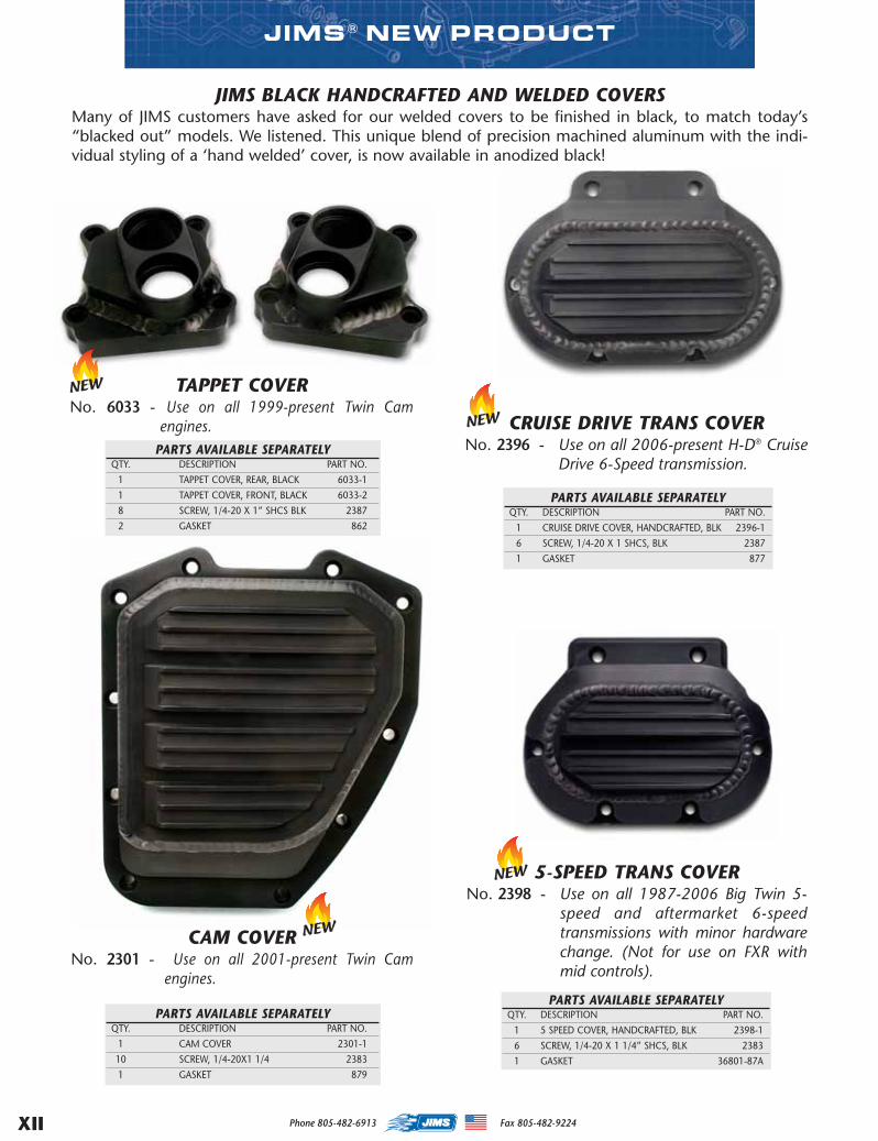
5 AND 6-SPEED COUNTERSHAFTBEARING REMOVER & INSTALLER TOOLThis new JIMS exclusive tool will install or removethe closed end countershaft bearing on all 5-Speedor 6-Speed Cruise Drive transmissions withoutusing a press, or tapping it in with a transmissionshaft. This is a precision hand tool designed toinstall the bearing squareand to the proper depth,the JIMS way. For moredetails see No. 739-IS instruc-tions.No. 739 - Use on all H-D®
Cruise Drive 6-Speeds and 1980-2006 5-Speeds -including after-market 6-speeds.
1
7
4
EXHAUST PIPE RETAININGRING INSTALLATION TOOL
Sometimes it’s the simple tool that makes the biggest difference. This patentpending installation tool quickly and easily installs the exhaust pipe retainingring on almost all H-D® exhaust systems. No more “flying and eye popping”retaining rings!!! This tool makes it easy to install the snap ring in secondswithout scratching the exhaust pipe or twisting the ring. For more details seeNo. 747-IS instructions.No. 747 - Use on all Twin Cam, Evo, and 1986-present Sportsters.
PARTS AVAILABLE SEPARATELYNO. QTY. DESCRIPTION PART NO.
1 1 DRIVER, EXHAUST RETAINER TOOL 747-1
2 1 CONE, EXHAUST RETAINER TOOL 747-2
3 1 INSTRUCTION SHEET 747-IS
1
2
5
6
32
PARTS AVAILABLE SEPARATELYNO. QTY. DESCRIPTION PART NO.
1 1 PULLER BAR 739-1
2 1 DRIVER, CRUISE DRIVE 739-2
3 1 DRIVER, 5 SPEED 739-3
4 1 STOP COLLAR 739-4
5 1 TOOL, SCREW 1024
6 1 SPUD 2190
7 1 BEARING 2010
1 O-RING 2310
1 INSTRUCTION SHEET 739-IS
INNER PRIMARY BEARING AND SEAL REMOVAL / INSTALLATION KITWhen it comes to servicing the inner primary bearing and seal, do it the JIMS way. This American madetool has a lifetime warranty and drives the bearing and seal perpendicular to the case without an arborpress. JIMS has been manufacturing the No. 967 Inner Primary Bearing andSeal Removal / Installation kit for over 6 years. We have taken its provendesign and added 2 new drivers to work on 2006 Dyna and all 2007 to pres-ent Big Twin models. This tool easily removes and installs the inner primaryroller bearing and installs the seal and bearing to factory specified depths.Now you can purchase kit No. 729 to work on all Big Twins from 1985 topresent; or if you have a JIMS No. 967 kit, you can upgrade it by purchasingthe two late model drivers. For more details see No. 729-IS instructions.No. 729 - Use on all 1985-present Big Twin Models.
21
3
7
9
486
5
Fax 805-482-9224
PARTS AVAILABLE SEPARATELYNO. QTY. DESCRIPTION PART NO.
1 1 SEAL INSTALLER 967-1
2 1 RECEIVER CUP EARLY 967-2
3 1 BEARING REMOVER EARLY 967-3
4 1 BEARING REMOVER LATE 967-4
5 1 BEARING REMOVER LATE 967-5
6 1 HEX BOLT 1211
7 2 WASHER 2038
8 1 BEARING 2010
9 1 NUT 2136
1 INSTRUCTION SHEET 729-IS
MASTER 2014 CAT INSERT proof.qxp:Layout 1 10/30/14 7:59 AM Page 9
Phone 805-482-6913 Fax 805-482-9224X
NEEDLE SHARP MULTIMETER PROBE KITToday’s wiring harnesses and fairings arefilled with hundreds of multiple gaugewires and connectors. This new kit has anassortment of needle sharp probes for pre-cise and non-damaging diagnostic work.Probes can be used with standard 4 mmbanana jack connections common withmost multimeters. The selection includes:Straight , 45°, and 90° probes (with 2probe diameters) for hard to reach termi-nals as well as standard alligator clips.
Similar kits on the market cost twice as much! All probes are fully insulated with 30v protection.No. 737 - 17 Pc needle sharp probe kit
TAPPET ADJUSTMENT TOOLDesigned and submitted by Hiro Koiso, a hands-on technician andJIMS sponsored Bonneville record holder in numerous classes; thispatent pending hand tool simplifies the way to verify proper tappetadjustment. After adjusting the tappet, simply insert the tip of thistool under the hydraulic unit retaining clip, above the pushrod seat.Similar to a “Go No-Go Gauge”, if the tip doesn’t fit between theclip and the pushrod seat OR if there is up and down end play,the tappet is out of adjustment. Only when the tip fits nicely withno end play is the tappet properly adjusted. For more details seeNo. 746-IS instructions.No. 746 - Use on most hydraulic tappets, OEM and aftermarket, for Twin Cam or Evo. (Does not work on
Solids, JIMS Hydrosolids or other limited travel tappets)
JIMS® NEW PRODUCT
HARDWARE ORGANIZERTired of hunting through plastic bins looking for hardware? Thepatent pending JIMS Hardware Organizers will guarantee all hard-ware is organized during powertrain teardown, storage, and finalassembly. The organizers include a specific stand for top end, camchest, transmission, and primary. When combined, they all nestwithin each other taking up very little space and can easily fit in adeep drawer of a tool box. When preparing for final assembly, thestands can be turned on end to expose threads for ease of loctiteapplication. The surface is powder coated in durable JIMS blue andincludes silkscreened hardware position art with select torquespecifications. For more details see No. 742-IS instructions.
No. 742 - Cam Chest - For cam cover, cam support and tappet coverhardware, 1999-present Twin Cam.
No. 743 - Primary - For inner and outer primary cover hardware,1970-present Big Twin.
No. 744 - Top End - For top end and rocker cover hardware,1999-present Twin Cam.
No. 745 - Transmission - For Cruise Drive transmission hardware,2007-present Twin Cam and 2006 Dyna models.
No. 742K - Complete Kit - Four piece hardware organizer kit listedabove
MASTER 2014 CAT INSERT proof.qxp:Layout 1 10/30/14 7:59 AM Page 10

Phone 805-482-6913 Fax 805-482-9224 XI
JIMS® NEW PRODUCT
SADDLEBAG LATCH RIVET TOOLSaddlebag latch replacement or tightening occurs often enough thatJIMS has developed a tool specifically for this purpose. This tool givessecure fastening while providing a clean factory look. To top it off, ourtool is substantially less expensive than tools offered by others to dothe same job, but ours still retains JIMS known quality. That is, our sad-dlebag latch rivet tool may be relatively inexpensive, but it is notcheap. Made in the USA, this tool also carries a lifetime guarantee. Formore details see No. 754-ISinstructions.No.754 - Use to crimp saddle-bag latch and hinge rivets.
LOCKDOWN AXLE KITHigh performance is much more than how much power a machinemakes or how fast it will go. At JIMS, we know reliability and safetyare also important. To these ends, we now offer our axle retentionupgrade kit. The OEM axle nut washer can become weakened ordeformed, and that can lead to loosening, even with a castle nut sys-tem. To avoid this loosening and the problems associated with it, wehave developed a much stronger part to replace the washer, alongwith superior adjuster plates for the final drive. Our kit includes aspecial slotted axle nutwasher part as well asstronger swing arm endcaps that have a better fit
into the swing arm. This is a great way to improve both reliabil-ity and safety. For more details see No. 1746-IS instructions.
No.1746 - Use on 1991-2005 Dyna Models.No.1747 - Use on 1979-04 XL, 1973-86 FL/FX and 1984 & 85 FXST Models.No.1748 - Use on 1980-2001 FLHT, 1982-2000 FXR.
PARTS AVAILABLE SEPARATELYNO. QTY. DESCRIPTION PART NO.
1 1 WELDMENT 754-8
2 1 SCREW 754-2
3 1 DEAD END 754-5
4 1 PILOT END 754-6
5 1 NICE BEARING 1186-1062
6 2 O-RING ( NOT SHOWN ) 2059-5
7 1 INSTRUCTION SHEET 754-IS
PARTS AVAILABLE SEPARATELYQTY. DESCRIPTION PART NO.
2 ADJUSTING PLATE, DYNA 1746-2
1 AXLE WASHER, DYNA 1746-1
2 ADJUSTING PLATE, FX/FL/XL 1747-2
1 AXLE WASHER, FX/FL/XL 1747-1
2 ADJUSTING PLATE, FLHT/FXR 1748-2
1 AXLE WASHER, FLHT/FXR 1748-1
1 INSTRUCTION SHEET 1746-IS
2
5
1
43
RIVETS AREAVAILABLE ATYOUR LOCALH-DDEALER
6
IGNITION SWITCH ALIGNMENT KEY FOR 2014 - PRESENT FLH MODELSThe professional technician needs fast and accurate alignmentof the ignition switch. Fiddling with screwdrivers and coathangers does not cut it! Our alignment tool is the perfect solu-tion; correct alignment is quickly and easily achieved. This toolis for 2014 and later touring models and is based on ourproven design for earlier models. Legendary JIMS qualityallows us to give a lifetime guarantee on this made in the USAtool. For more details see No. 943-IS instructions.No.944 - Use on 2014-present Touring Models.
MASTER 2014 CAT INSERT proof.qxp:Layout 1 10/30/14 7:59 AM Page 11
Phone 805-482-6913 Fax 805-482-9224XII
JIMS® NEW PRODUCT
JIMS BLACK HANDCRAFTED AND WELDED COVERSMany of JIMS customers have asked for our welded covers to be finished in black, to match today’s“blacked out” models. We listened. This unique blend of precision machined aluminum with the indi-vidual styling of a ‘hand welded’ cover, is now available in anodized black!
PARTS AVAILABLE SEPARATELYQTY. DESCRIPTION PART NO.
1 TAPPET COVER, REAR, BLACK 6033-1
1 TAPPET COVER, FRONT, BLACK 6033-2
8 SCREW, 1/4-20 X 1” SHCS BLK 2387
2 GASKET 862
CAM COVERNo. 2301 - Use on all 2001-present Twin Cam
engines.
PARTS AVAILABLE SEPARATELYQTY. DESCRIPTION PART NO.
1 CAM COVER 2301-1
10 SCREW, 1/4-20X1 1/4 2383
1 GASKET 879
5-SPEED TRANS COVERNo. 2398 - Use on all 1987-2006 Big Twin 5-
speed and aftermarket 6-speedtransmissions with minor hardwarechange. (Not for use on FXR withmid controls).
PARTS AVAILABLE SEPARATELYQTY. DESCRIPTION PART NO.
1 5 SPEED COVER, HANDCRAFTED, BLK 2398-1
6 SCREW, 1/4-20 X 1 1/4” SHCS, BLK 2383
1 GASKET 36801-87A
PARTS AVAILABLE SEPARATELYQTY. DESCRIPTION PART NO.
1 CRUISE DRIVE COVER, HANDCRAFTED, BLK 2396-1
6 SCREW, 1/4-20 X 1 SHCS, BLK 2387
1 GASKET 877
CRUISE DRIVE TRANS COVERNo. 2396 - Use on all 2006-present H-D® Cruise
Drive 6-Speed transmission.
TAPPET COVERNo. 6033 - Use on all 1999-present Twin Cam
engines.
MASTER 2014 CAT INSERT proof.qxp:Layout 1 10/30/14 7:59 AM Page 12
SECTIONCYLINDER HEAD COOLER, FUEL INJECTION .........................................
CYLINDER, PISTON, & FLYWHEEL KITS .....................................................
STROKER ACCESSORIES...............................................................................
IGNITION .................................................................................................................
PISTONS.................................................................................................................
ROLLER ROCKER ARMS, & SHAFTS..........................................................
VALVES, GUIDES, & SEATS .............................................................................
SPRINGS, PUSHRODS, & CAMS ..................................................................
TAPPETS, & TAPPET BLOCKS.......................................................................
LATCH COVERS, & FRONT HEAD MOUNT ...............................................
HANDCRAFTED COVERS...............................................................................
CAM COVERS, CAM BEARINGS, & BUSHINGS .....................................
CRANK PINS, & HARDWARE ..........................................................................
SPROCKET SHAFTS, PINION SHAFTS, & HARDWARE.......................
ROD ROLLERS, RACES, & BUSHINGS .......................................................
OIL PUMPS, HARDWARE, & BREATHER GEARS ....................................
STARTERS, CABLES, & CLUTCHES ............................................................
TRANSMISSIONS, & PARTS ..........................................................................
GASKETS, & SEALS...........................................................................................
COMPLETE TOOL SECTION .........................................................SEE TAB
This Catalog Was Printed In The U.S.A. ©Copyright JIMS® 2012
Dealer No.
JIMS®
555 DAWSON DRIVECAMARILLO, CA 93012
WWW.JIMSUSA.COM
1
2
3
4
5
6
7
8
9
10
11
12
13
14
15
16
17
18
19
20
ENGINE................................................................................................PREFACE
1
MASTER 2013 CATALOG_JMS 2.qxp:Layout 1 8/2/12 8:25 PM Page 1
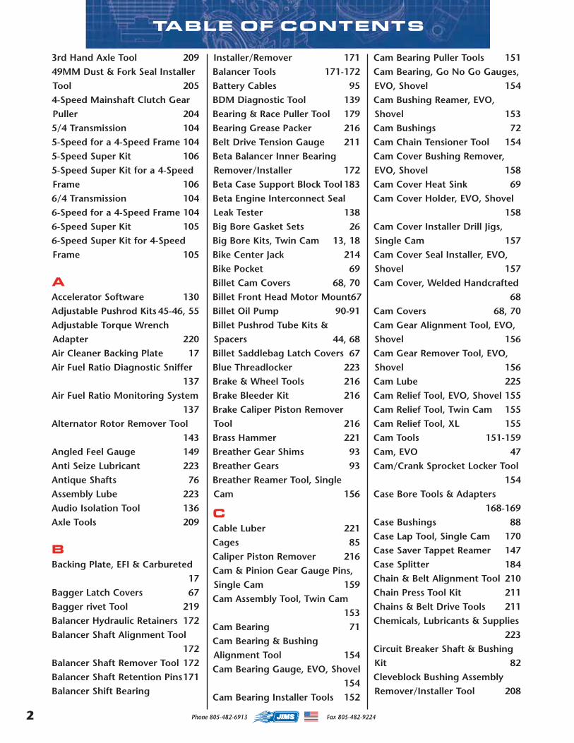
TABLE OF CONTENTS
3rd Hand Axle Tool 20949MM Dust & Fork Seal InstallerTool 2054-Speed Mainshaft Clutch GearPuller 2045/4 Transmission 1045-Speed for a 4-Speed Frame 1045-Speed Super Kit 1065-Speed Super Kit for a 4-SpeedFrame 1066/4 Transmission 1046-Speed for a 4-Speed Frame 1046-Speed Super Kit 1056-Speed Super Kit for 4-SpeedFrame 105
AAccelerator Software 130Adjustable Pushrod Kits 45-46, 55Adjustable Torque WrenchAdapter 220Air Cleaner Backing Plate 17Air Fuel Ratio Diagnostic Sniffer
137Air Fuel Ratio Monitoring System
137Alternator Rotor Remover Tool
143Angled Feel Gauge 149Anti Seize Lubricant 223Antique Shafts 76Assembly Lube 223Audio Isolation Tool 136Axle Tools 209
BBacking Plate, EFI & Carbureted
17Bagger Latch Covers 67Bagger rivet Tool 219Balancer Hydraulic Retainers 172Balancer Shaft Alignment Tool
172Balancer Shaft Remover Tool 172Balancer Shaft Retention Pins171Balancer Shift Bearing
Installer/Remover 171Balancer Tools 171-172Battery Cables 95BDM Diagnostic Tool 139Bearing & Race Puller Tool 179Bearing Grease Packer 216Belt Drive Tension Gauge 211Beta Balancer Inner BearingRemover/Installer 172Beta Case Support Block Tool 183Beta Engine Interconnect SealLeak Tester 138Big Bore Gasket Sets 26Big Bore Kits, Twin Cam 13, 18Bike Center Jack 214Bike Pocket 69Billet Cam Covers 68, 70Billet Front Head Motor Mount67Billet Oil Pump 90-91Billet Pushrod Tube Kits &Spacers 44, 68Billet Saddlebag Latch Covers 67Blue Threadlocker 223Brake & Wheel Tools 216Brake Bleeder Kit 216Brake Caliper Piston RemoverTool 216Brass Hammer 221Breather Gear Shims 93Breather Gears 93Breather Reamer Tool, SingleCam 156
CCable Luber 221Cages 85Caliper Piston Remover 216Cam & Pinion Gear Gauge Pins,Single Cam 159Cam Assembly Tool, Twin Cam
153Cam Bearing 71Cam Bearing & BushingAlignment Tool 154Cam Bearing Gauge, EVO, Shovel
154Cam Bearing Installer Tools 152
Cam Bearing Puller Tools 151Cam Bearing, Go No Go Gauges,EVO, Shovel 154Cam Bushing Reamer, EVO,Shovel 153Cam Bushings 72Cam Chain Tensioner Tool 154Cam Cover Bushing Remover,EVO, Shovel 158Cam Cover Heat Sink 69Cam Cover Holder, EVO, Shovel
158Cam Cover Installer Drill Jigs,Single Cam 157Cam Cover Seal Installer, EVO,Shovel 157Cam Cover, Welded Handcrafted
68Cam Covers 68, 70Cam Gear Alignment Tool, EVO,Shovel 156Cam Gear Remover Tool, EVO,Shovel 156Cam Lube 225Cam Relief Tool, EVO, Shovel 155Cam Relief Tool, Twin Cam 155Cam Relief Tool, XL 155Cam Tools 151-159Cam, EVO 47Cam/Crank Sprocket Locker Tool
154Case Bore Tools & Adapters
168-169Case Bushings 88Case Lap Tool, Single Cam 170Case Saver Tappet Reamer 147Case Splitter 184Chain & Belt Alignment Tool 210Chain Press Tool Kit 211Chains & Belt Drive Tools 211Chemicals, Lubricants & Supplies
223Circuit Breaker Shaft & BushingKit 82Cleveblock Bushing AssemblyRemover/Installer Tool 208
2 Phone 805-482-6913 Fax 805-482-9224
MASTER 2013 CATALOG_JMS 2.qxp:Layout 1 8/2/12 8:25 PM Page 2
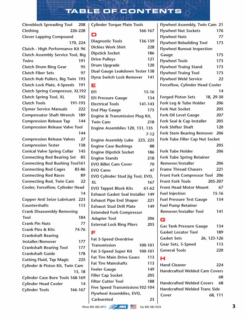
TABLE OF CONTENTS
Cleveblock Spreading Tool 208Clothing 226-228Clover Lapping Compound
170, 224Clutch - High Performance Kit 96Clutch Assembly Service Tool, BigTwins 191Clutch Drum Ring Gear 95Clutch Fiber Sets 97Clutch Hub Pullers, Big Twin 193Clutch Lock Plate, 4-Speeds 191Clutch Spring Compressor, XL192Clutch Spring Tool, XL 192Clutch Tools 191-193Clymer Service Manuals 222Compensator Shaft Wrench 189Compression Release Tap 144Compression Release Valve Tool
144Compression Release Valves 27Compression Tester 138Conical Valve Spring Collar 145Connecting Rod Bearing Set 85Connecting Rod Bushing Tool161Connecting Rod Cages 85-86Connecting Rod Races 89Connecting Rod, Twin Cam 22Cooler, Forceflow, Cylinder Head
14Copper Anti Seize Lubricant 223Countershafts 113Crank Disassembly RemovingTool 184Crank Pin Nuts 77Crank Pins & Kits 74-76Crankshaft BearingInstaller/Remover 177Crankshaft Bearing Tool 177Crankshaft Guide 178Cutting Fluid, Tap Magic 225Cylinder & Piston Kit, Twin Cam
13, 18Cylinder Case Bore Tools 168-169Cylinder Head Cooler 14Cylinder Tools 166-167
Cylinder Torque Plate Tools166-167
DDiagnostic Tools 136-139Dickies Work Shirt 228Dipstick Socket 186Drive Pulleys 121Drum Upgrade 120Dual Gauge Leakdown Tester 138Dyna Switch Lock Remover 141
EEFI 15-16EFI Pressure Gauge 134Electrical Tools 141-143End Play Gauge 175Engine & Transmission Plug Kit,Twin Cam 218Engine Assemblies 120, 131, 135
7-12Engine Assembly Lube 223, 225Engine Case Bushings 88Engine Dipstick Socket 186Engine Stands 218EVO Billet Cam Cover 70EVO Cams 47EVO Cylinder Stud Jig Tool, EVO,XL 167EVO Tappet Block Kits 61-62Exhaust Gasket Seal Installer 149Exhaust Pipe End Shaper 221Exhaust Stud Drill Plate 149Extended Fork CompressorAdapter Tool 206External Lock Ring Pliers 203
FFat 5-Speed OverdriveTransmission 100-101Fat 5-Speed Super Kit 100-101Fat Tire Main Drive Gears 113Fat Tire Mainshafts 113Feeler Gauge 149Filler Cap Socket 205Filter Cutter Tool 188Five Speed Transmissions102-104Flywheel Assemblies, EVO,Carbureted 23
Flywheel Assembly, Twin Cam 21Flywheel Nut Sockets 176Flywheel Nuts 77Flywheel Rebuilding Tool 173Flywheel Runout InspectionGauge 175Flywheel Tools 173Flywheel Truing Stand 173Flywheel Truing Tool 173Flywheel Weld Service 22Forceflow, Cylinder Head Cooler
14Forged Piston Sets 18, 29-30Fork Leg & Tube Holder 206Fork Nut Socket 205Fork Oil Level Gauge 207Fork Seal & Cap Installer 205Fork Shifter Shaft 120Fork Stem Bearing Remover 206Fork Tube Filler Cap Nut Socket
205Fork Tube Holder 206Fork Tube Spring RetainerRemover/Installer 206Frame Thread Chasers 221Front Fork Compressor Tool 206Front Fork Tools 205-207Front Head Motor Mount 67Fuel Injection 15-16Fuel Pressure Test Gauge 134Fuel Pump RetainerRemover/Installer Tool 141
GGas Tank Pressure Gauge 134Gasket Locator Tool 189Gasket Sets 26, 123-126Gear Sets, 5-Speed 113General Tools 220
HHand Cleaner 224Handcrafted Welded Cam Covers
68Handcrafted Welded Covers 68Handcrafted Welded Trans SideCover 68, 111
3Phone 805-482-6913 Fax 805-482-9224
MASTER 2013 CATALOG_JMS 2.qxp:Layout 1 8/2/12 8:25 PM Page 3
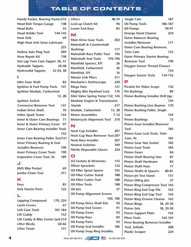
TABLE OF CONTENTS
Handy Packer, Bearing Packer216Head Bolt Torque Gauge 148Head Bolts 33Head Holder Tool 144-145Heat Sink 69High Heat Anti Seize Lubricant
223Hollow Axle Plug Tool 209Hose Repair Kit 138Hot Lap Twin Cam Tappet 50, 57Hydraulic Tappets 50-58Hydrosolid Tappets 52-54, 58
IIdler Gear Shaft 82Ignition & Fuel Pump Tools 141Ignition Module, Carbureted
13, 28Ignition SwitchConnector/Remover Tool 141Indian Drive Shaft 76Inline Spark Tester 143Inner & Outer Cam Bearings 71Inner & Outer Primary Cover 97Inner Cam Bearing Installer Tools
152Inner Cam Bearing Puller Tool151Inner Primary Bearing & SealInstaller/Remover 190Inner Primary Cover Tools 190Inspection Cover Tool, XL 189
JJIMS Bike Pocket 69Jumbo Chain Tool 211
KKeys 83Kick Starter Parts 122
LLapping Compound 170, 224Latch Covers 67Left Case Tools 181-184Lift Caddy 132Lift Caddy & Bike Center Jack 214Lifter Blocks 60-66Lifter Tester 131
Lifters 48-59Lock-up Clutch Kit 96Lower End Keys 83
MMain Drive Gear Tools 202Mainshaft & CountershaftBushings 117Mainshaft Race Puller Tool 196Mainshaft Seal Tools 195-196Manifold Spacers, EFI 26Manifold, Carbureted 26Manifold, EFI 16Master Link Pliers 211Mechanic’s Stethoscope 220Mega Nuts 121Mighty Bite Flywheel Lock 176Mini Valve Spring Tester 132, 145Modular Engine & TransmissionStands 217Module, Carbureted 13, 28Motor Assemblies 7-12Motorcycle Alignment Tool 210
NNeck Cup Installer 207Neck Cup Race Remover Tool 207Neck Race Installer 207Neutral Switches 109Nitrile Disposable Gloves 224
OO2 Sockets & Wrenches 135Offset Sprockets 122Oil Filler Spout Spacer 103Oil Filter Cutter Stand 188Oil Filter Cutter Tool 188Oil Filter Tools 188Oil Jets 27Oil Pump Alignment Screws
160, 186Oil Pump Drive Shaft Kits 92Oil Pump End Covers 91Oil Pump Gears 92Oil Pump Keys 83Oil Pump Parts 92Oil Pump Seal Installer 186Oil Pump Snap Ring Installer,
Single Cam 187Oil Pump Tools 186-187Oil Pumps 90-91Orange Hand Cleaner 224Outer Balancer BearingInstaller/Remover 171Outer Cam Bearing Remover,Twin Cam 153Outer Primary Starter BearingRemover Tool 190Oxygen Sensor Thread Chasers
134Oxygen Sensor Tools 134-135
PPicstick for Video Scope 136Pin Bushings 89Pinion Bushing Installer Drill Jigs
159Pinion Bushing Line Reamer 170Pinion Bushing Puller, SingleCam 159Pinion Bushings 73Pinion Gear Installer/RemoverTool 185Pinion Gear Lock Tools, TwinCam, XL 185Pinion Gear Nut Socket 185Pinion Gear Tools 185Pinion Gears 84Pinion Shaft Bearing Sets 87Pinion Shaft Hardware 82Pinion Shaft Nuts 77Pinion Shafts & Spacers 80-81Piston Jet Test Stand 131Piston Oiling Jets 27Piston Ring Compressor Tool 165Piston Ring End Gap File 165Piston Ring End Gap Tool 164Piston Ring Groove Cleaner 165Piston Rings 18, 29-30Piston Sets 18, 29-30Piston Support Plate 163Piton Tools 163-165Pivot Bearing Remover/InstallerTool, Softails 208Plastic Scraper 224
4 Phone 805-482-6913 Fax 805-482-9224
MASTER 2013 CATALOG_JMS 2.qxp:Layout 1 8/2/12 8:25 PM Page 4
TABLE OF CONTENTS
Plug Kit, Twin Cam Engine &Transmission 219Points Cover 69, 70Powerglide™ Tappets
48-49, 51, 53-55, 57Powertrain Alignment Tool,Touring Models 210Primary Cover Kit 97Primary Drive Tools 189-190Primary Locking Bars 189Pulley Locker Tools 194Pulley Tools 194Pulleys 121Pump Retainer Tool 141Pushrod Cover Clip Installer Tool
44, 145Pushrod Cover Seal/Seat Cutter,Single Cam 160Pushrod Kit 45-46, 55Pushrod Tube Covers & Spacers
44, 68
RRace & Bearing Installer/RemoverHandle 152, 181, 207, 213Real Wheel Compensator BearingRemover/Installer Tool 213Reamer, Rocker Arm Bushing 150Reamers, Valve Guides 38, 147Rear Axle Nut Torque AdapterTool 209Rear Fork BearingRemover/Installer Tool 208Rear Wheel Alignment Tool 209Receptacle & Pin Extractor 142Red Threadlocker 223Remote Start Button 143Retention Pins 171Right Side Drive Transmission
98-99Ring Compressor Tool 165Ring File 165Ring Groove Cleaner Tool 165Ring Installer Tool 164rivet Tool 219Rocker Arm Bushing InstallerTool 150
Rocker Arm Bushing or BearingPuller 150Rocker Arm Bushing Reamer 150Rocker Arm Bushings & RollerHardware 34Rocker Arm Sets 31-32Rocker Arm Shafts 33Rocker Cover Ratchet Wrench148Rod Alignment Tool 161Rod Bushings 89Rod Holder Tool 161Rod Race Installer Tool 162Rod Race Lapping Set 162Rod Races 89Rod Rollers 85-86Rod Tools 161-162Rods, Twin Cam 22Roller Bearings 85-87Roller Rocker Arm Sets 31-32Rotor Remover Tool 143RSD Super Kits 99RSD Transmission 98-99Rubber Gloves 224
SSaddlebag rivet Tool 219Safer Scraper 224Scantool, Diagnostics 139Seat Installer/Remover Tool 207Service Manuals 222Shift Fork Gauge Tools 204Shift Fork Shaft Remover Tool,Cruise Drive 203Shifter Drum Kit 120Shifter Drum Parts 120Shifter Levers 119Shifter Shaft Case SleeveRemover/Installer 203Shifter Shaft Seal Tools 195Shovel Tappet Block Kits
60, 64-66Six Speed OverdriveTransmissions 102-104Slim Jim Filter Wrench 188Sniffer, AFR Tool 137Soft Vice Jaws 220Solid Brass Hammer 221
Solid Tappets & Hardware56, 58-59
Sound Isolation Tool 136Spark Plug Thread Chasers 142Spark Tester 143Speedo Transmission Parts 119Spoke Wrench 215Spout Spacer 103Spring Compressor Tool 145Sprocket Bearing Installer Tool,Big Twin 178Sprocket Bearing Installer Tool,XL 178Sprocket Shaft Bearing NutWrench 183Sprocket Shaft Bearing Tools 178Sprocket Shaft Bearing Tools
181-182Sprocket Shaft Hard Cap 184Sprocket Shaft Holders 173-174Sprocket Shaft Nuts 77Sprocket Shaft Race Handle Tool
181Sprocket Shaft RaceRemover/Installer 181Sprocket Shaft Rotators 174Sprocket Shaft Seal Installer 181Sprocket Shaft Seal Installer 183Sprocket Shaft Spacers 81Sprocket Shafts 79Sprockets 122Staking Dowel Pin for Bushings
158Star Receptacle Extractors 142Started Jack Seal Installer 190Starter Button Tool 143Starter Ring Gear Kit 95Starter Ring Gear Rivet Fixture
191Starters 94Steel O-Clip Pincer Tool 187Steering Head Stem Nut Wrench
205Stem Nut Wrench 205Stroker Accessories 26-27Stroker Flywheel Assemblies,
5Phone 805-482-6913 Fax 805-482-9224
MASTER 2013 CATALOG_JMS 2.qxp:Layout 1 8/2/12 8:25 PM Page 5
7
TABLE OF CONTENTS
EVO, Carbureted 24Stroker Flywheel Assemblies,Twin Cam 21Stroker Kit Gasket Sets 26Stroker Kit, Twin Cam "A" & "B"
19-20Surface Temperature IndicatingStrips 212Sweatshirt 228Swing Arm & Rear Fork Tools 208Swingarm, Frame & AlignmentTools 209-210Switch Housing Alignment Tool
141
TTap Magic Cutting Fluid 225Tappet Block Alignment Tool 160Tappet Block Clearancing Cutter
160Tappet Block Kits 60-61, 63Tappet Block Tools 160-186Tappet Covers, Twin Cam 60, 68Tappet Guide Puller Tool, XL 160Tappet Pump Test Stand 131Tappet Reamer, Twin Cam 147Tappet Rollers 59Tappet Screen Plug Tool 187Tappets 48-59Thread Chasers 134, 142, 221Thread Locker 223Throttle Body 15-16Timing Cover 69, 70Timken Bearing Installer 182Timken Bearing Removers 180Timken Bearing Simulator 182Timken Bearing/Race InstallerAdapter Kit 179Timken Case Conversion Tool133Timken Case Snap RingRemover/Installer 182Timken Replacement Sleeve 133Tire Air Pressure Gauge 216Tire Rotator Tool 215Top End Kits, Twin Cam13,18,124Top Fork Tube Socket 205Top Lid, Transmission 111
Torco Assembly Spray Lube 225Torco Cam Lube 225Torque Plates 166-167Torx 9 Piece Bit Set 220Torx, 7-in-1 Key Set 220Transmission Bearings 114-116Transmission Bushings 117Transmission Cases 109Transmission Countershafts 113Transmission Gear & BearingTools 197-198Transmission Gear Spacing Tool,Sportster 203Transmission Gears, Five Speed
112-113Transmission Mainshafts 113Transmission Parts 108-122Transmission Races 116Transmission Rebuild Kits 108Transmission Rebuild Service 107Transmission Retainers 118Transmission Seals 126Transmission Side Covers 68, 111Transmission Sprocket ShaftSpacers 117Transmission Sprockets 122Transmission Stands 218Transmission Stud Installer Tool
204Transmission Trap Doors 110Transmissions 98-104Trap Door Bearing Tools 199-201Trap Door Pullers 200-201Trap Doors, Billet 110Truing Stand, Wheels 215T-Shirts 226-228Twin Cam Case Splitter 184
UUniversal Bearing Packer 216
VValve Guide Go No Go Gauge149Valve Guide Pusher Set 148Valve Guide Reamers 38, 147Valve Guide Seal Cutter 148Valve Guide Seal Installer Tool
146Valve Guide SealInstaller/Remover Tools 146Valve Guides 38Valve Lapper Tool 148Valve Seats 39Valve Spring Compressor Tool145Valve Spring Kits, Seats & Locks
40-43Valve Spring Seat Cutter 148Valve Spring Tester 132, 145Valve Train Tools 144-150Valves 36-37Vice Soft Jaws 220Video Scope 136V-Rod Clutch Hub AlignmentTool 192V-Rod Clutch Hub Locking Tool
193
WWEGO III Wide Band AFRMonitoring System 137Welded Tappet Covers 60, 68Wheel Bearing Locknut Wrench
216Wheel Bearing RaceRemover/Installer Tool 213Wheel Bearing Remover/InstallerKit 212Wheel Rotator Tool 215Wheel Tools 212-213Wheel Truing Stand 215Wire Piercing Tool 142Wrist Pin Bushing Reamers 161Wrist Pin BushingRemover/Installer Tool 161Wrist Pin Bushings 89Wrist Pin Clip Tools 162-163Wrist Pin Tools 162-163
6 Phone 805-482-6913 Fax 805-482-9224
MASTER 2013 CATALOG_JMS 2.qxp:Layout 1 8/2/12 8:25 PM Page 6
7 7
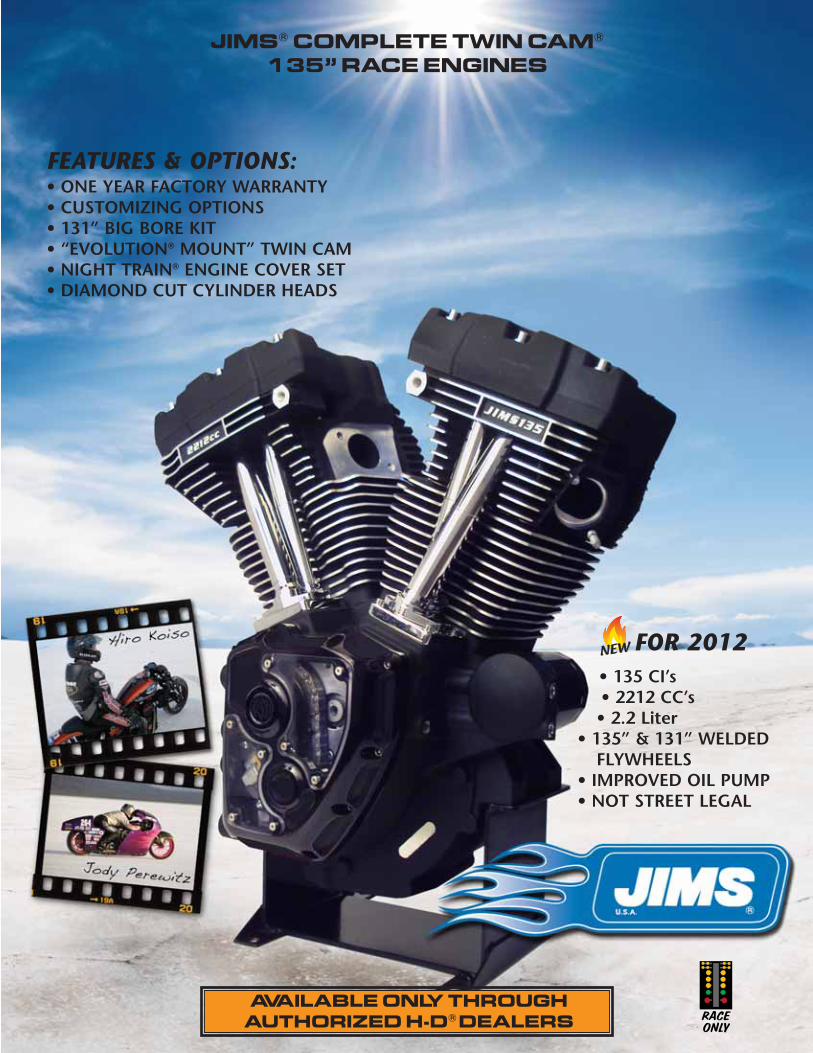
JIMS® COMPLETE TWIN CAM®
135” RACE ENGINES
AVAILABLE ONLY THROUGHAUTHORIZED H-D® DEALERS
FOR 2012• 135 CI’s• 2212 CC’s• 2.2 Liter
• 135” & 131” WELDEDFLYWHEELS
• IMPROVED OIL PUMP• NOT STREET LEGAL
NEW
FEATURES & OPTIONS:• ONE YEAR FACTORY WARRANTY• CUSTOMIZING OPTIONS• 131” BIG BORE KIT• “EVOLUTION® MOUNT” TWIN CAM• NIGHT TRAIN® ENGINE COVER SET• DIAMOND CUT CYLINDER HEADS
RACEONLY
8
RACEONLY
JIMS® COMPLETE TWIN CAM® 135”RACE ENGINES
2608-3530 Black 07-Pres. Touring & 06-Pres. Dyna2608-3535 Silver 07-Pres. Touring & 06-Pres. Dyna2208-3530 Black 99-06 Touring & 99-05 Dyna2208-3535 Silver 99-06 Touring & 99-05 Dyna
Part No. Color Description
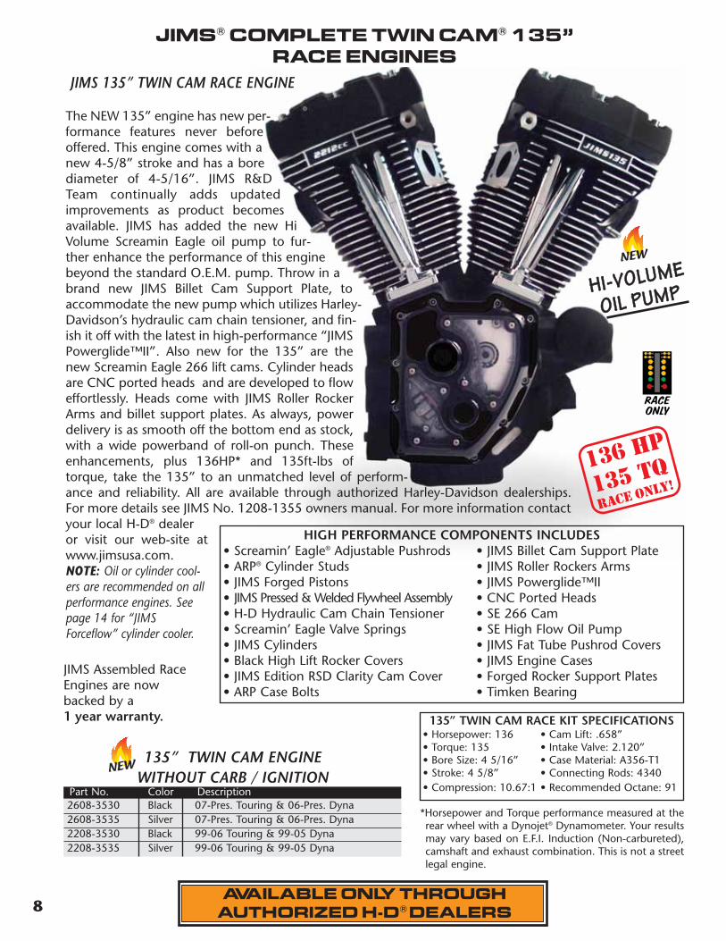
JIMS 135” TWIN CAM RACE ENGINE
The NEW 135” engine has new per-formance features never beforeoffered. This engine comes with anew 4-5/8” stroke and has a borediameter of 4-5/16”. JIMS R&DTeam continually adds updatedimprovements as product becomesavailable. JIMS has added the new HiVolume Screamin Eagle oil pump to fur-ther enhance the performance of this enginebeyond the standard O.E.M. pump. Throw in abrand new JIMS Billet Cam Support Plate, toaccommodate the new pump which utilizes Harley-Davidson’s hydraulic cam chain tensioner, and fin-ish it off with the latest in high-performance “JIMSPowerglide™II”. Also new for the 135” are thenew Screamin Eagle 266 lift cams. Cylinder headsare CNC ported heads and are developed to floweffortlessly. Heads come with JIMS Roller RockerArms and billet support plates. As always, powerdelivery is as smooth off the bottom end as stock,with a wide powerband of roll-on punch. Theseenhancements, plus 136HP* and 135ft-lbs oftorque, take the 135” to an unmatched level of perform-ance and reliability. All are available through authorized Harley-Davidson dealerships.For more details see JIMS No. 1208-1355 owners manual. For more information contactyour local H-D® dealeror visit our web-site atwww.jimsusa.com.NOTE: Oil or cylinder cool-ers are recommended on allperformance engines. Seepage 14 for “JIMSForceflow” cylinder cooler.
JIMS Assembled RaceEngines are nowbacked by a1 year warranty.
HIGH PERFORMANCE COMPONENTS INCLUDES• Screamin’ Eagle® Adjustable Pushrods • JIMS Billet Cam Support Plate• ARP® Cylinder Studs • JIMS Roller Rockers Arms• JIMS Forged Pistons • JIMS Powerglide™II• JIMS Pressed & Welded Flywheel Assembly • CNC Ported Heads• H-D Hydraulic Cam Chain Tensioner • SE 266 Cam• Screamin’ Eagle Valve Springs • SE High Flow Oil Pump• JIMS Cylinders • JIMS Fat Tube Pushrod Covers• Black High Lift Rocker Covers • JIMS Engine Cases• JIMS Edition RSD Clarity Cam Cover • Forged Rocker Support Plates• ARP Case Bolts • Timken Bearing
136 HP
135 TQrace only!
AVAILABLE ONLY THROUGHAUTHORIZED H-D® DEALERS
RACEONLY
135” TWIN CAM RACE KIT SPECIFICATIONS• Horsepower: 136 • Cam Lift: .658”• Torque: 135 • Intake Valve: 2.120”• Bore Size: 4 5/16” • Case Material: A356-T1• Stroke: 4 5/8” • Connecting Rods: 4340• Compression: 10.67:1 • Recommended Octane: 91
135” TWIN CAM ENGINEWITHOUT CARB / IGNITION
HHII--VVOOLLUUMMEE
OOIILL PPUUMMPP
NEW
*Horsepower and Torque performance measured at therear wheel with a Dynojet® Dynamometer. Your resultsmay vary based on E.F.I. Induction (Non-carbureted),camshaft and exhaust combination. This is not a streetlegal engine.
NEW
9
RACE
ONLY
JIMS® COMPLETE TWIN CAM® 131” RACE ENGINES
1308-3530 Black 1999-2006 Touring and 1999-2005 Dyna®
1708-3530 Black 2007-Later Touring 2006-Later Dyna 1308-3535 Silver 1999-2006 Touring and 1999-2005 Dyna 1708-3535 Silver 2007-Later Touring 2006-Later Dyna 1508-3530 Black 2000-2006 Softail1508-3535 Silver 2000-2006 Softail2108-3530 Black 2007-Later Softail2108-3535 Silver 2007-Later Softail
Part No. Color Description
131” TWIN CAM ENGINE WITHOUT CARB / IGNITION
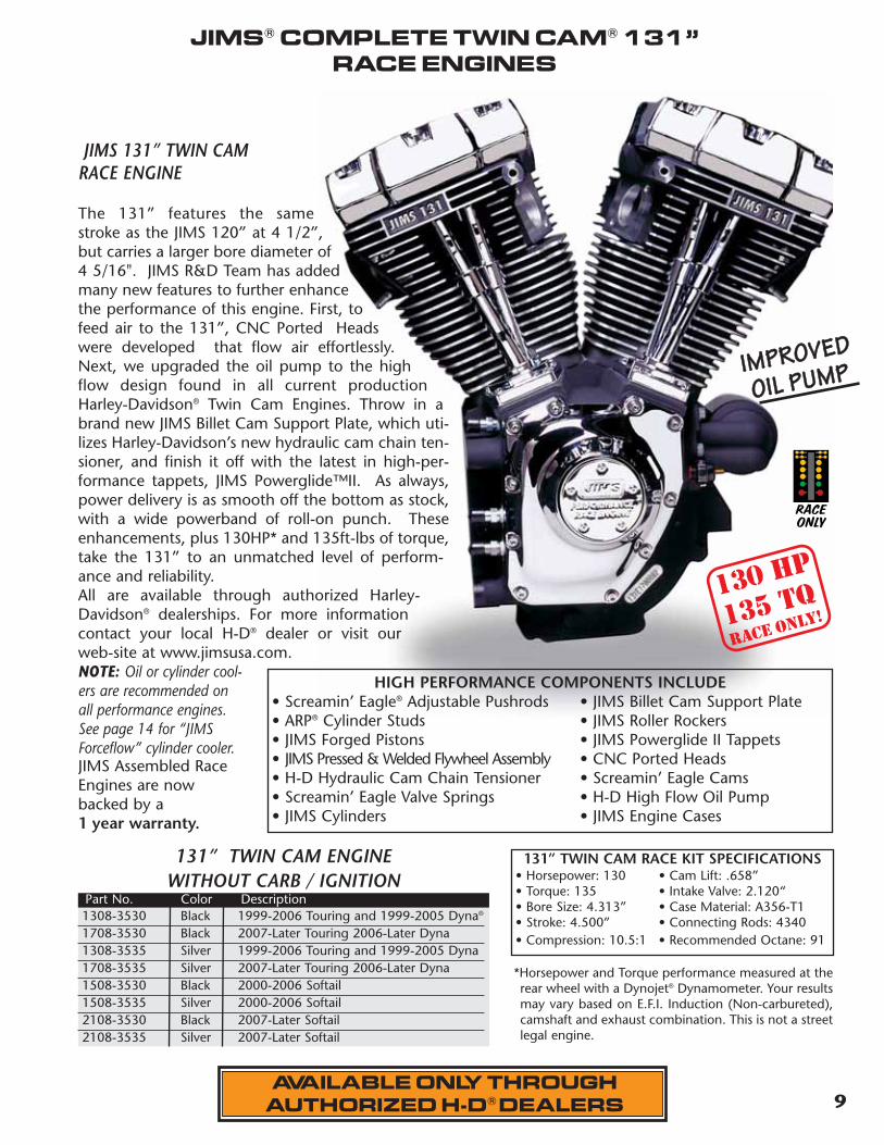
JIMS 131” TWIN CAMRACE ENGINE
The 131” features the samestroke as the JIMS 120” at 4 1/2”,but carries a larger bore diameter of4 5/16". JIMS R&D Team has addedmany new features to further enhancethe performance of this engine. First, tofeed air to the 131”, CNC Ported Headswere developed that flow air effortlessly.Next, we upgraded the oil pump to the highflow design found in all current productionHarley-Davidson® Twin Cam Engines. Throw in abrand new JIMS Billet Cam Support Plate, which uti-lizes Harley-Davidson’s new hydraulic cam chain ten-sioner, and finish it off with the latest in high-per-formance tappets, JIMS Powerglide™II. As always,power delivery is as smooth off the bottom as stock,with a wide powerband of roll-on punch. Theseenhancements, plus 130HP* and 135ft-lbs of torque,take the 131” to an unmatched level of perform-ance and reliability. All are available through authorized Harley-Davidson® dealerships. For more informationcontact your local H-D® dealer or visit ourweb-site at www.jimsusa.com. NOTE: Oil or cylinder cool-ers are recommended onall performance engines.See page 14 for “JIMSForceflow” cylinder cooler.JIMS Assembled RaceEngines are nowbacked by a 1 year warranty.
HIGH PERFORMANCE COMPONENTS INCLUDE• Screamin’ Eagle® Adjustable Pushrods • JIMS Billet Cam Support Plate• ARP® Cylinder Studs • JIMS Roller Rockers• JIMS Forged Pistons • JIMS Powerglide II Tappets• JIMS Pressed & Welded Flywheel Assembly • CNC Ported Heads • H-D Hydraulic Cam Chain Tensioner • Screamin’ Eagle Cams• Screamin’ Eagle Valve Springs • H-D High Flow Oil Pump• JIMS Cylinders • JIMS Engine Cases
130 HP
135 TQrace only!
*Horsepower and Torque performance measured at therear wheel with a Dynojet® Dynamometer. Your resultsmay vary based on E.F.I. Induction (Non-carbureted),camshaft and exhaust combination. This is not a streetlegal engine.
AVAILABLE ONLY THROUGHAUTHORIZED H-D® DEALERS
RACEONLY
IIMMPPRROOVVEEDD
OOIILL PPUUMMPP
131” TWIN CAM RACE KIT SPECIFICATIONS• Horsepower: 130 • Cam Lift: .658”• Torque: 135 • Intake Valve: 2.120“• Bore Size: 4.313” • Case Material: A356-T1• Stroke: 4.500” • Connecting Rods: 4340• Compression: 10.5:1 • Recommended Octane: 91

10
JIMS 120" TWIN CAM RACE ENGINESDelivering 125 HP* and 121 ft-lbs of torque is just the beginning. JIMS thick-walled cases offerunmatched strength and can support a bore size of up to 4.800. This engine features pressed flywheels,forged pistons, Screamin’ Eagle® valve springs, forged 4340 steel connecting rods and the latest in highperformance tappets, JIMS Powerglide™II. From the ground up, this engine has everything needed tostop the competition in its tracks, and the track is what this engine was designed for. Since 2004, JIMShas set the standard in High-Performance Twin Cam Racing Engines, and we are just getting started!.NOTE: Oil or cylinder coolers are recommended on all performance engines. See page 14 for “JIMS Forceflow” cylinder cooler.
HIGH PERFORMANCE COMPONENTS INCLUDE• Screamin’ Eagle Adjustable Pushrods • ARP® Cylinder Studs• JIMS Roller Rockers • JIMS Forged Pistons• JIMS Powerglide II Tappets • Screamin’ Eagle Cams• JIMS Pressed & Welded Flywheel Assembly • Screamin’ Eagle Valve Springs• JIMS Cylinder • JIMS Engine Cases
120” TWIN CAM RACE KIT SPECIFICATIONS• Horsepower: 125 • Cam Lift: .658”• Torque: 121 • Intake Valve: 2.120“• Bore Size: 4.125” • Case Material: A356-T1• Stroke: 4.500” • Connecting Rods: 4340• Compression: 10:1 • Recommended Octane: 91
1208-3530 Black 1999-2006 Touring and 1999-2005 Dyna1608-3530 Black 2007-Later Touring 2006-Present Dyna1208-3535 Silver 1999-2006 Touring and 1999-2005 Dyna1608-3535 Silver 2007-Later Touring 2006-Present Dyna
Part No. Color Description
120” TWIN CAM ENGINE WITHOUT CARB / IGNITION
1408-3530 Black 2000-2006 Softail1408-3535 Silver 2000-2006 Softail2008-3530 Black 2007-Later Softail2008-3535 Silver 2007-Later Softail
Part No. Color Description
120” TWIN CAM ENGINE WITHOUT CARB / IGNITION
JIMS® COMPLETE TWIN CAM® 120”RACE ENGINES
*Horsepower and Torque performance measured at the rear wheel with a Dynojet® Dynamometer. Your results may varybased on E.F.I. Induction (Non-carbureted), camshaft and exhaust combination. This is not a street legal engine.
Softail® Touring & Dyna®
125 HP
121 TQrace only!
AVAILABLE ONLY THROUGHAUTHORIZED H-D® DEALERS
RACEONLY
RACEONLY
135" TWIN CAM® ENGINE WITHOUT CARB / IGNITION
11
JIMS® COMPLETE TWIN CAM® 135”, 131” & 120”WITH EVOLUTION® MOTOR MOUNT
AVAILABLE ONLY THROUGHAUTHORIZED H-D® DEALERS
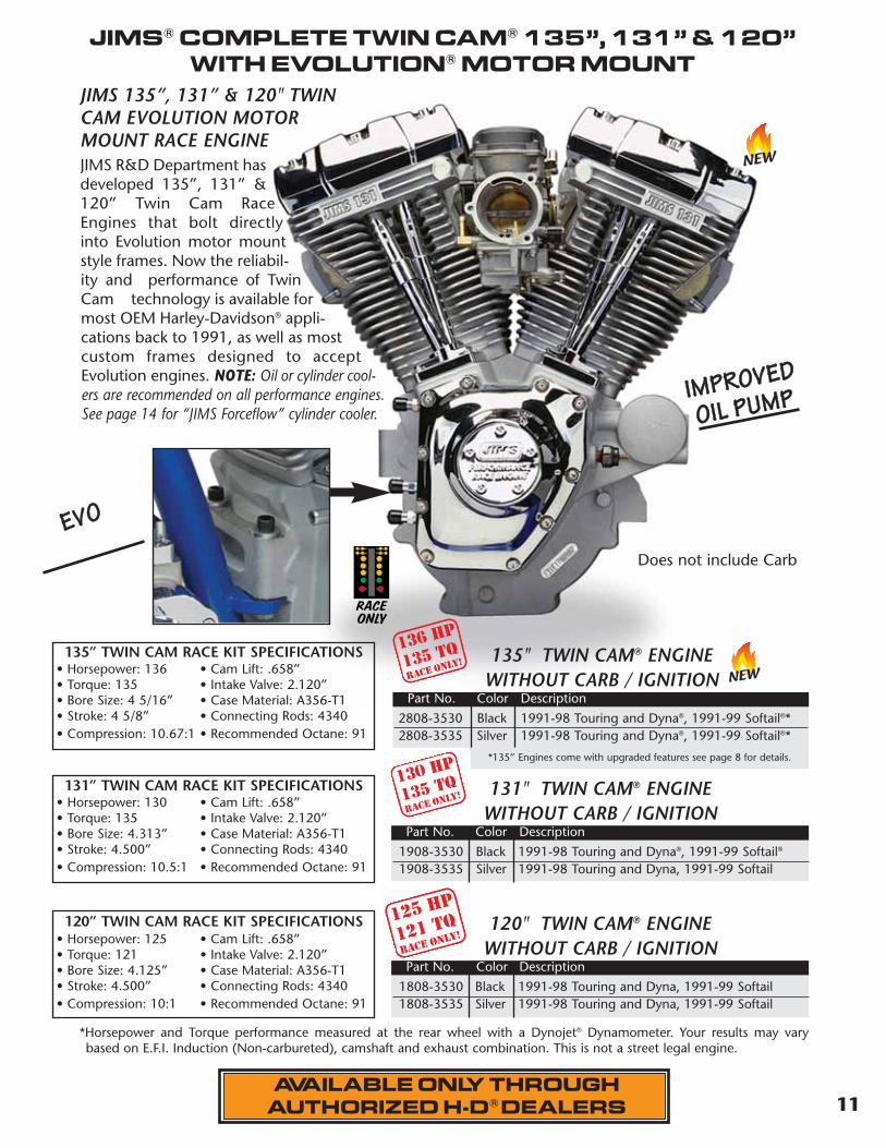
JIMS 135”, 131” & 120" TWINCAM EVOLUTION MOTORMOUNT RACE ENGINEJIMS R&D Department hasdeveloped 135”, 131” &120” Twin Cam RaceEngines that bolt directlyinto Evolution motor mountstyle frames. Now the reliabil-ity and performance of TwinCam technology is available formost OEM Harley-Davidson® appli-cations back to 1991, as well as mostcustom frames designed to acceptEvolution engines. NOTE: Oil or cylinder cool-ers are recommended on all performance engines.See page 14 for “JIMS Forceflow” cylinder cooler.
1808-3530 Black 1991-98 Touring and Dyna, 1991-99 Softail1808-3535 Silver 1991-98 Touring and Dyna, 1991-99 Softail
Part No. Color Description
120" TWIN CAM® ENGINE WITHOUT CARB / IGNITION
1908-3530 Black 1991-98 Touring and Dyna®, 1991-99 Softail®
1908-3535 Silver 1991-98 Touring and Dyna, 1991-99 Softail
Part No. Color Description
131" TWIN CAM® ENGINE WITHOUT CARB / IGNITION
Does not include Carb
125 HP
121 TQrace only!
130 HP
135 TQrace only!
*Horsepower and Torque performance measured at the rear wheel with a Dynojet® Dynamometer. Your results may varybased on E.F.I. Induction (Non-carbureted), camshaft and exhaust combination. This is not a street legal engine.
131” TWIN CAM RACE KIT SPECIFICATIONS• Horsepower: 130 • Cam Lift: .658”• Torque: 135 • Intake Valve: 2.120”• Bore Size: 4.313” • Case Material: A356-T1• Stroke: 4.500” • Connecting Rods: 4340• Compression: 10.5:1 • Recommended Octane: 91
120” TWIN CAM RACE KIT SPECIFICATIONS• Horsepower: 125 • Cam Lift: .658”• Torque: 121 • Intake Valve: 2.120”• Bore Size: 4.125” • Case Material: A356-T1• Stroke: 4.500” • Connecting Rods: 4340• Compression: 10:1 • Recommended Octane: 91
RACEONLY
EEVVOO
IIMMPPRROOVVEEDD
OOIILL PPUUMMPP
2808-3530 Black 1991-98 Touring and Dyna®, 1991-99 Softail®*2808-3535 Silver 1991-98 Touring and Dyna®, 1991-99 Softail®*
Part No. Color Description
136 HP
135 TQrace only!
135” TWIN CAM RACE KIT SPECIFICATIONS• Horsepower: 136 • Cam Lift: .658”• Torque: 135 • Intake Valve: 2.120”• Bore Size: 4 5/16” • Case Material: A356-T1• Stroke: 4 5/8” • Connecting Rods: 4340• Compression: 10.67:1 • Recommended Octane: 91
*135” Engines come with upgraded features see page 8 for details.
NEW
NEW
12
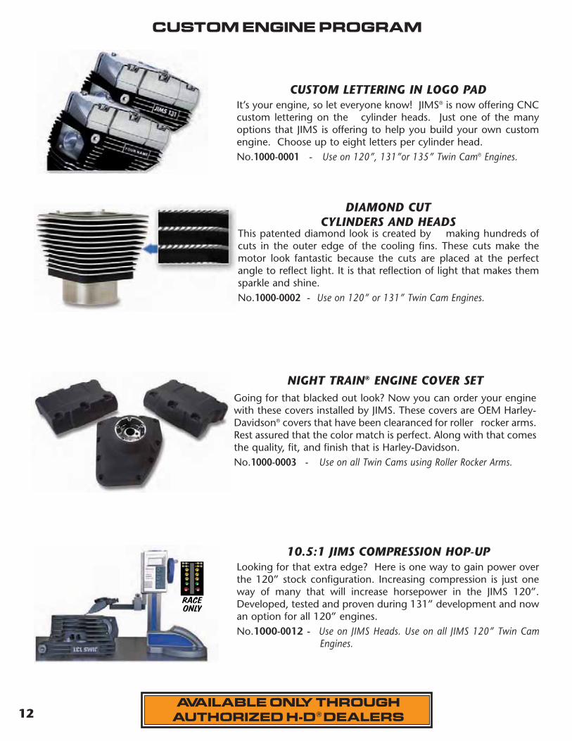
It’s your engine, so let everyone know! JIMS® is now offering CNCcustom lettering on the cylinder heads. Just one of the manyoptions that JIMS is offering to help you build your own customengine. Choose up to eight letters per cylinder head.No.1000-0001 - Use on 120”, 131”or 135” Twin Cam® Engines.
This patented diamond look is created by making hundreds ofcuts in the outer edge of the cooling fins. These cuts make themotor look fantastic because the cuts are placed at the perfectangle to reflect light. It is that reflection of light that makes themsparkle and shine.No.1000-0002 - Use on 120” or 131” Twin Cam Engines.
Going for that blacked out look? Now you can order your enginewith these covers installed by JIMS. These covers are OEM Harley-Davidson® covers that have been clearanced for roller rocker arms.Rest assured that the color match is perfect. Along with that comesthe quality, fit, and finish that is Harley-Davidson.No.1000-0003 - Use on all Twin Cams using Roller Rocker Arms.
Looking for that extra edge? Here is one way to gain power overthe 120” stock configuration. Increasing compression is just oneway of many that will increase horsepower in the JIMS 120”.Developed, tested and proven during 131” development and nowan option for all 120” engines. No.1000-0012 - Use on JIMS Heads. Use on all JIMS 120” Twin Cam
Engines.
CUSTOM LETTERING IN LOGO PAD
DIAMOND CUT CYLINDERS AND HEADS
NIGHT TRAIN® ENGINE COVER SET
10.5:1 JIMS COMPRESSION HOP-UP
CUSTOM ENGINE PROGRAM
AVAILABLE ONLY THROUGHAUTHORIZED H-D® DEALERS
RACEONLY
MASTER 2013 CATALOG_JMS 2.qxp:Layout 1 8/2/12 8:25 PM Page 12

13
DO YOU HAVE A 120” AND WISH YOU HAD A 131”?
An easy solution to convert your JIMS 120" into a 131”. These kits are designed to work with anexisting JIMS 120" Race Engine. The kit includes a set of 4 5/16" JIMS cylinders and a set of 4 5/16" JIMSpistons. These are the same cylinders and pistons used in the JIMS 131" race engine. Since the 131"engine was based on the same stroke as the 120", other parts, including the flywheel assembly, cams,etc... can still be used. With simple case boring - and this kit - your 120" can be converted into the awe-some 131" engine. Kit includes head and base gaskets and a center case bolt.With proper induction, exhaust and head modifications, this Big Bore kit will easily match the poweroutput of the JIMS 131" race engine. This kit offers a great cost alternative for the customer that hasalready purchased a JIMS 120” engine. See instruction sheet No.1308-1350 on JIMS website. Use JIMS casebore tool No.1400 on page 168.No.1000-0010 - JIMS 131 Big Bore Kit (Black) Use on all 1999 to present Alpha’s JIMS 120” Twin Cam® EnginesNo.1000-0011 - JIMS 131 Big Bore Kit (Silver) Use on all 1999 to present Alpha’s JIMS 120” Twin Cam® Engines
JIMS® 131" BIG BORE KIT...
See your local authorized Harley-Davidson dealer and build your custom engine today. For more information contact your local H-D® dealer or visit our web-site at www.jimsusa.com
AVAILABLE ONLY THROUGHAUTHORIZED H-D® DEALERS
RACEONLY
JIMS® TWIN CAM CARBURATED RACE ENGINE IGNITIONThis is the perfect match up for your 120”, 131” or 135” performancerace engine. JIMS R&D department developed this program to giveyou instant acceleration off the line and smooth and even transitionthrough the gears. This unit has the OEM style plug connector and iseasy to install. This product is not included with engines. Order sepa-rately. No.2344 - Use on all 1999 to 2003 Alpha 120”, 131” or 135” carbureted
engines.Use on all 2000 to 2003 Beta 120”, 131” or 135” carburetedengines.
NEW
MASTER 2013 CATALOG_JMS 2.qxp:Layout 1 8/2/12 8:26 PM Page 13

Phone 805-482-6913 Fax 805-482-922414
1
JIMS FORCEFLOW
THE JIMS FORCEFLOW CYLINDER HEAD COOLER This smooth streamline design will keep your Twin Cam® running cooler on those hot July summerdays in stop and go traffic. JIMS® R & D department has come up with a serious way to drop yourhead temperature by as much as100 degrees. Although this mountsin the horn area JIMS has designeda horn relocater hidden inside thefan housing. The fan can beinstalled to be turned on and offmanually or it can be regulated bya thermostat controlled sensor thatmonitors head temperature andactivates the fan when engine tem-perature rises. This kit is highly rec-ommended for performancemotors to help extend engine life.Complete kit includes high pow-ered fan, housing, horn, hardwareand all wiring, along with detailedinstructions. For more details see No.5400-IS instructions.USE ON 99-PRESENT TWIN CAM TOURING MODELS & OTHER MODELS WITH SOME FABRICATION. (Kit installs from horn location & is supported by center case bolt location.)No. 5400 - Polished Cylinder Head Fan kit. No. 5401 - Black Cylinder Head Fan kit. No. 5402 - Silver Cylinder Head Fan kit.No. 5447 - JIMS Engine Hardware Mounting kit.
It’s commonknowledge thatheat is one ofan enginesworst enemies.In developing
the JIMS cylinder head cooler, JIMS had to sacrificea few motors for the cause. We tested worse casescenario by letting engines idle in the sunfor over a half hour each while recordingcylinder head temperatures minute byminute. Above represents the averagetemperature reduction ofall testing combined. TheJIMS Cylinder HeadCooler will help anengine operate and stabi-lize at lower temperatures.
This solid model view shows the fanhousing withhigh velocity fanand suppliedrelocated minihorn.
NEW
MASTER 2013 CATALOG_JMS 2.qxp:Layout 1 8/2/12 8:26 PM Page 14
15
1
Phone 805-482-6913 Fax 805-482-9224
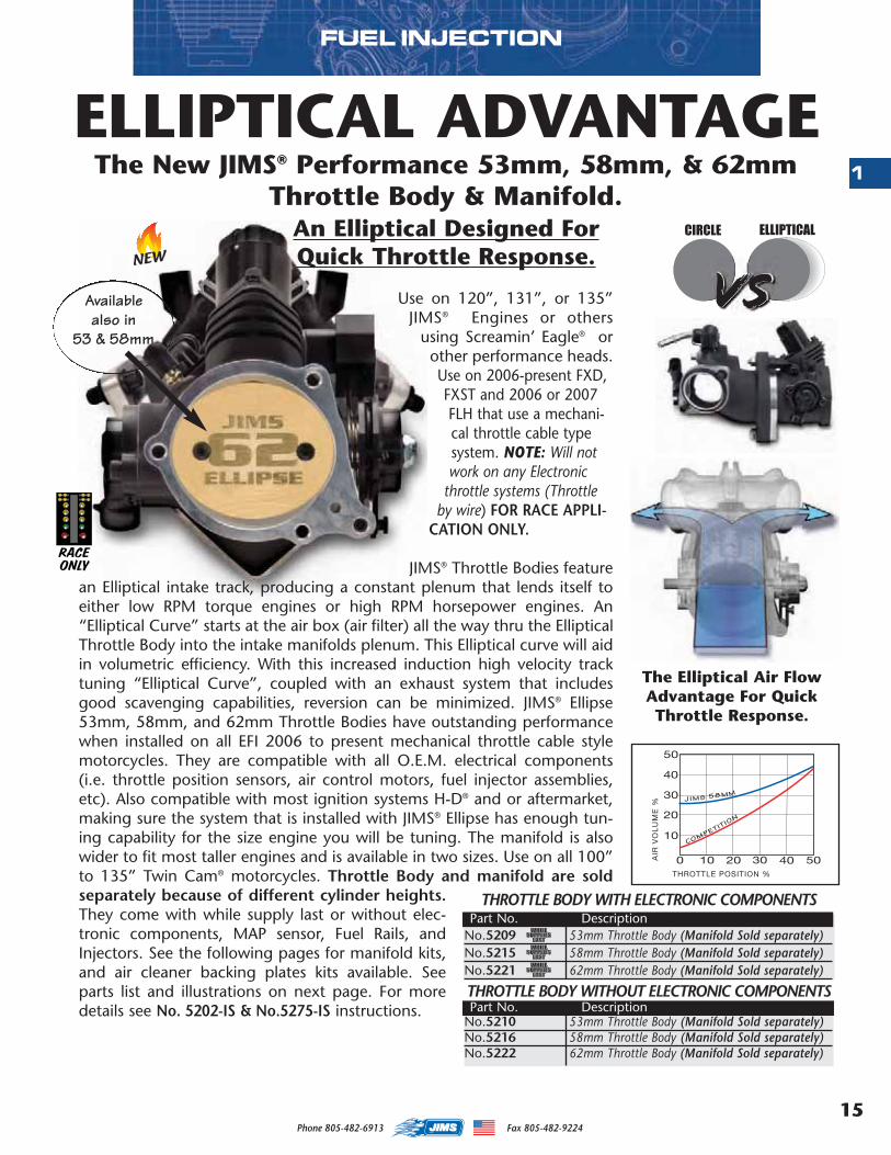
Use on 120”, 131”, or 135”JIMS® Engines or others
using Screamin’ Eagle® orother performance heads.Use on 2006-present FXD,FXST and 2006 or 2007FLH that use a mechani-cal throttle cable typesystem. NOTE: Will notwork on any Electronic
throttle systems (Throttleby wire) FOR RACE APPLI-
CATION ONLY.
JIMS® Throttle Bodies featurean Elliptical intake track, producing a constant plenum that lends itself toeither low RPM torque engines or high RPM horsepower engines. An“Elliptical Curve” starts at the air box (air filter) all the way thru the EllipticalThrottle Body into the intake manifolds plenum. This Elliptical curve will aidin volumetric efficiency. With this increased induction high velocity tracktuning “Elliptical Curve”, coupled with an exhaust system that includesgood scavenging capabilities, reversion can be minimized. JIMS® Ellipse53mm, 58mm, and 62mm Throttle Bodies have outstanding performancewhen installed on all EFI 2006 to present mechanical throttle cable stylemotorcycles. They are compatible with all O.E.M. electrical components(i.e. throttle position sensors, air control motors, fuel injector assemblies,etc). Also compatible with most ignition systems H-D® and or aftermarket,making sure the system that is installed with JIMS® Ellipse has enough tun-ing capability for the size engine you will be tuning. The manifold is alsowider to fit most taller engines and is available in two sizes. Use on all 100”to 135” Twin Cam® motorcycles. Throttle Body and manifold are soldseparately because of different cylinder heights.They come with while supply last or without elec-tronic components, MAP sensor, Fuel Rails, andInjectors. See the following pages for manifold kits,and air cleaner backing plates kits available. Seeparts list and illustrations on next page. For moredetails see No. 5202-IS & No.5275-IS instructions.
FUEL INJECTION
The New JIMS® Performance 53mm, 58mm, & 62mmThrottle Body & Manifold.
An Elliptical Designed ForQuick Throttle Response.
ELLIPTICAL ADVANTAGE
VSCIRCLE ELLIPTICAL
RACEONLY
Availablealso in
53 & 58mm
The Elliptical Air FlowAdvantage For QuickThrottle Response.
THROTTLE BODY WITH ELECTRONIC COMPONENTS
No.5209 53mm Throttle Body (Manifold Sold separately)No.5215 58mm Throttle Body (Manifold Sold separately)No.5221 62mm Throttle Body (Manifold Sold separately)
THROTTLE BODY WITHOUT ELECTRONIC COMPONENTS
No.5210 53mm Throttle Body (Manifold Sold separately)No.5216 58mm Throttle Body (Manifold Sold separately)No.5222 62mm Throttle Body (Manifold Sold separately)
Part No. Description
Part No. Description
NEW
MASTER 2013 CATALOG_JMS 2.qxp:Layout 1 8/2/12 8:26 PM Page 15
Phone 805-482-6913 Fax 805-482-922416
1
FUEL INJECTION
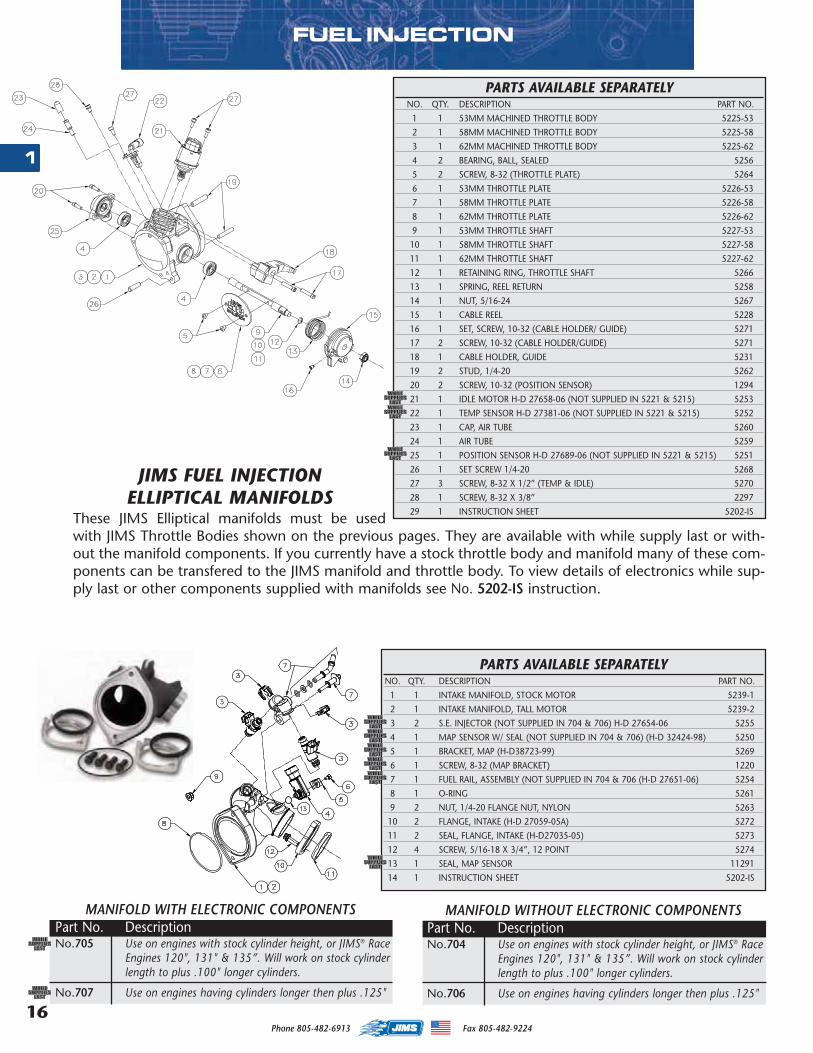
JIMS FUEL INJECTION ELLIPTICAL MANIFOLDS
These JIMS Elliptical manifolds must be usedwith JIMS Throttle Bodies shown on the previous pages. They are available with while supply last or with-out the manifold components. If you currently have a stock throttle body and manifold many of these com-ponents can be transfered to the JIMS manifold and throttle body. To view details of electronics while sup-ply last or other components supplied with manifolds see No. 5202-IS instruction.
MANIFOLD WITH ELECTRONIC COMPONENTSPart No. DescriptionNo.705 Use on engines with stock cylinder height, or JIMS® Race
Engines 120", 131" & 135”. Will work on stock cylinderlength to plus .100" longer cylinders.
No.707 Use on engines having cylinders longer then plus .125"
PARTS AVAILABLE SEPARATELYNO. QTY. DESCRIPTION PART NO.
1 1 INTAKE MANIFOLD, STOCK MOTOR 5239-1
2 1 INTAKE MANIFOLD, TALL MOTOR 5239-2
3 2 S.E. INJECTOR (NOT SUPPLIED IN 704 & 706) H-D 27654-06 5255
4 1 MAP SENSOR W/ SEAL (NOT SUPPLIED IN 704 & 706) (H-D 32424-98) 5250
5 1 BRACKET, MAP (H-D38723-99) 5269
6 1 SCREW, 8-32 (MAP BRACKET) 1220
7 1 FUEL RAIL, ASSEMBLY (NOT SUPPLIED IN 704 & 706 (H-D 27651-06) 5254
8 1 O-RING 5261
9 2 NUT, 1/4-20 FLANGE NUT, NYLON 5263
10 2 FLANGE, INTAKE (H-D 27059-05A) 5272
11 2 SEAL, FLANGE, INTAKE (H-D27035-05) 5273
12 4 SCREW, 5/16-18 X 3/4”, 12 POINT 5274
13 1 SEAL, MAP SENSOR 11291
14 1 INSTRUCTION SHEET 5202-IS
PARTS AVAILABLE SEPARATELYNO. QTY. DESCRIPTION PART NO.
1 1 53MM MACHINED THROTTLE BODY 5225-53
2 1 58MM MACHINED THROTTLE BODY 5225-58
3 1 62MM MACHINED THROTTLE BODY 5225-62
4 2 BEARING, BALL, SEALED 5256
5 2 SCREW, 8-32 (THROTTLE PLATE) 5264
6 1 53MM THROTTLE PLATE 5226-53
7 1 58MM THROTTLE PLATE 5226-58
8 1 62MM THROTTLE PLATE 5226-62
9 1 53MM THROTTLE SHAFT 5227-53
10 1 58MM THROTTLE SHAFT 5227-58
11 1 62MM THROTTLE SHAFT 5227-62
12 1 RETAINING RING, THROTTLE SHAFT 5266
13 1 SPRING, REEL RETURN 5258
14 1 NUT, 5/16-24 5267
15 1 CABLE REEL 5228
16 1 SET, SCREW, 10-32 (CABLE HOLDER/ GUIDE) 5271
17 2 SCREW, 10-32 (CABLE HOLDER/GUIDE) 5271
18 1 CABLE HOLDER, GUIDE 5231
19 2 STUD, 1/4-20 5262
20 2 SCREW, 10-32 (POSITION SENSOR) 1294
21 1 IDLE MOTOR H-D 27658-06 (NOT SUPPLIED IN 5221 & 5215) 5253
22 1 TEMP SENSOR H-D 27381-06 (NOT SUPPLIED IN 5221 & 5215) 5252
23 1 CAP, AIR TUBE 5260
24 1 AIR TUBE 5259
25 1 POSITION SENSOR H-D 27689-06 (NOT SUPPLIED IN 5221 & 5215) 5251
26 1 SET SCREW 1/4-20 5268
27 3 SCREW, 8-32 X 1/2” (TEMP & IDLE) 5270
28 1 SCREW, 8-32 X 3/8” 2297
29 1 INSTRUCTION SHEET 5202-IS
MANIFOLD WITHOUT ELECTRONIC COMPONENTSPart No. DescriptionNo.704 Use on engines with stock cylinder height, or JIMS® Race
Engines 120", 131" & 135”. Will work on stock cylinderlength to plus .100" longer cylinders.
No.706 Use on engines having cylinders longer then plus .125"
MASTER 2013 CATALOG_JMS 2.qxp:Layout 1 8/2/12 8:26 PM Page 16
17
1
Phone 805-482-6913 Fax 805-482-9224
EFI & CARB AIR CLEANER BACKING PLATE KITS
1111
1717
1616
1414
1313
1212 1515
1010 9 8
PARTS AVAILABLE SEPARATELYNO. QTY. DESCRIPTION PART NO.
1 3 SCREW, 1/4-20 X 1/2”, BHCS, BLK, AIR ELEMENT 8090
2 1 AIR ELEMENT (H-D® #29244-08 OR K&N #HD-0818) 5277
3 3 STANDOFF, FILTER 5279
4 2 PLUG, BLACK BACKING PLATE 5278-1
5 2 BOLT, BREATHER, VENTED 5283
6 1 BACKING PLATE, BLACK, JIMS EFI 5281-1 & 5280-1
7 1 BACKING PLATE, BLACK, HD EFI 5282-1 & 5280-1
8 1 BACKING PLATE, BLACK, STOCK DELPHI EFI 5284-1 & 5280-1
9 1 BACKING PLATE ASSY, CHROME, JIMS EFI 5289
10 1 BACKING PLATE ASSY, CHROME, 58MM EFI BY WIRE 5290
11 1 BACKING PLATE ASSY, CHROME, STOCK DELPHI 5291
12 1 GASKET, BACKING PLATE, JIMS EFI 876
13 3 SCREW, 1/4-20 X 1 1/4”, BHCS, BLK, BACKING PLATE 2166
14 2 O-RING, BREATHER STANDOFF 874
15 1 GASKET, BACKING PLATE, HD 58MM BY WIRE EFI 875
16 1 GASKET, BACKING PLATE, FOR STOCK DELPHI 884
17 2 PLUG, CHROME, BACKING PLATE 5275-2
18 1 INSTRUCTION SHEET 5275-IS
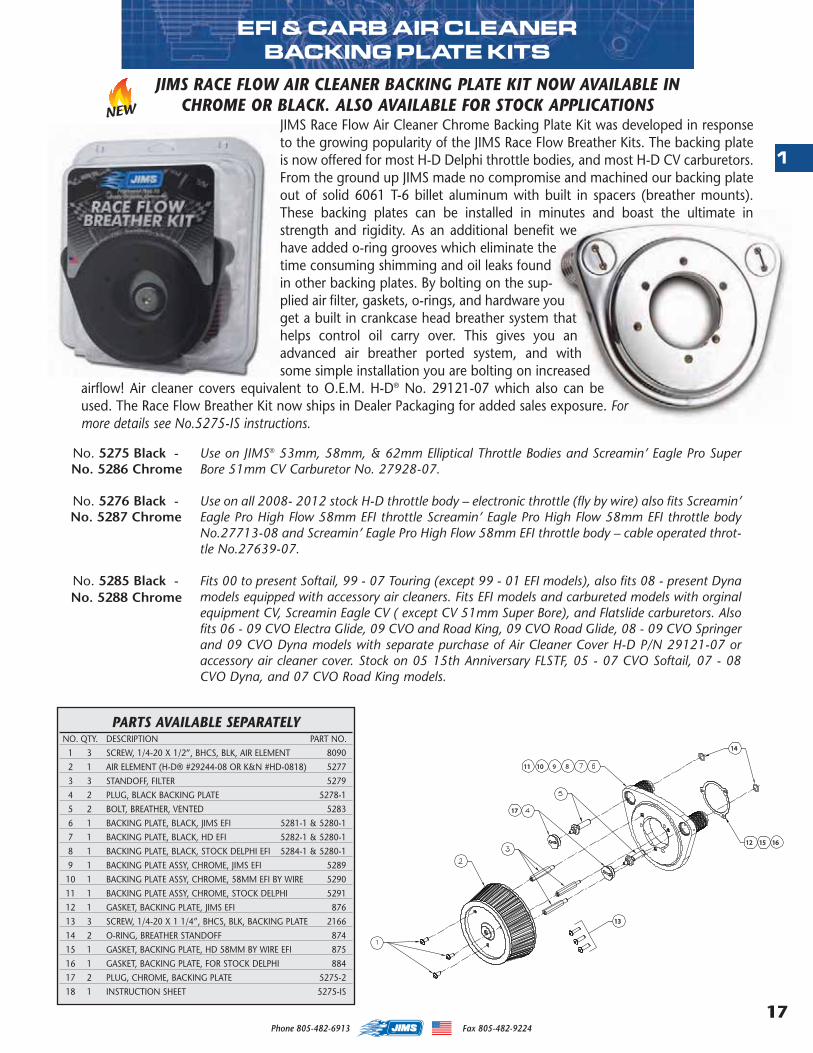
No. 5275 Black - Use on JIMS® 53mm, 58mm, & 62mm Elliptical Throttle Bodies and Screamin’ Eagle Pro SuperBore 51mm CV Carburetor No. 27928-07.
No. 5276 Black - Use on all 2008- 2012 stock H-D throttle body – electronic throttle (fly by wire) also fits Screamin’Eagle Pro High Flow 58mm EFI throttle Screamin’ Eagle Pro High Flow 58mm EFI throttle bodyNo.27713-08 and Screamin’ Eagle Pro High Flow 58mm EFI throttle body – cable operated throt-tle No.27639-07.
No. 5285 Black - Fits 00 to present Softail, 99 - 07 Touring (except 99 - 01 EFI models), also fits 08 - present Dynamodels equipped with accessory air cleaners. Fits EFI models and carbureted models with orginalequipment CV, Screamin Eagle CV ( except CV 51mm Super Bore), and Flatslide carburetors. Alsofits 06 - 09 CVO Electra Glide, 09 CVO and Road King, 09 CVO Road Glide, 08 - 09 CVO Springerand 09 CVO Dyna models with separate purchase of Air Cleaner Cover H-D P/N 29121-07 oraccessory air cleaner cover. Stock on 05 15th Anniversary FLSTF, 05 - 07 CVO Softail, 07 - 08CVO Dyna, and 07 CVO Road King models.
JIMS RACE FLOW AIR CLEANER BACKING PLATE KIT NOW AVAILABLE IN CHROME OR BLACK. ALSO AVAILABLE FOR STOCK APPLICATIONS
JIMS Race Flow Air Cleaner Chrome Backing Plate Kit was developed in responseto the growing popularity of the JIMS Race Flow Breather Kits. The backing plateis now offered for most H-D Delphi throttle bodies, and most H-D CV carburetors.From the ground up JIMS made no compromise and machined our backing plateout of solid 6061 T-6 billet aluminum with built in spacers (breather mounts).These backing plates can be installed in minutes and boast the ultimate instrength and rigidity. As an additional benefit wehave added o-ring grooves which eliminate thetime consuming shimming and oil leaks foundin other backing plates. By bolting on the sup-plied air filter, gaskets, o-rings, and hardware youget a built in crankcase head breather system thathelps control oil carry over. This gives you anadvanced air breather ported system, and withsome simple installation you are bolting on increased
airflow! Air cleaner covers equivalent to O.E.M. H-D® No. 29121-07 which also can beused. The Race Flow Breather Kit now ships in Dealer Packaging for added sales exposure. Formore details see No.5275-IS instructions.
NEW
No. 5286 Chrome
No. 5287 Chrome
No. 5288 Chrome
MASTER 2013 CATALOG_JMS 2.qxp:Layout 1 8/2/12 8:26 PM Page 17
Phone 805-482-6913 Fax 805-482-922418
2
Alpha & Beta Black Cylinder w/Piston Set No.1501B No.1519
Alpha & Beta Silver Cylinder w/Piston Set No.1501 No.1520
Alpha Black Cylinder w/Piston Set No.1521 No.1523 No.1525 No.1527
Alpha Silver Cylinder w/Piston Set No.1522 No.1524 No.1526 No.1528
Beta Black Cylinder w/Piston Set No.1548 No.1550
Beta Silver Cylinder w/Piston Set No.1549 No.1551
Stroke 4” 4” 4.375” 4.375” 4.5” 4.625”
Bore 4” 4.125” 4” 4.125” 4.125” 4.125”
Cylinder Length 4.915” 4.915” 5.018” 4.915” 5.018” 5.018”
Standard Piston Set Part No.’s No.1603 No.1614 No.1615 Alpha No.1616 Alpha No.1611 Alpha No.1617
Standard Piston Set Part No.’s Beta No.1613 Beta No.1618
2 Piston Ring Set Standard No.’s No.1491 No.1286-1354 No.1491 No.1286-1354 No.1286-1354 No.1286-1354
Compression Height 1.27 1.27 1.1750 1.0825 1.1990 1.1250
* Compression W/ Stock H-D® 85cc Head 9.56:1 10.00:1 10.00:1
** Compression W/ S. E. 95cc Head 10.5:1 10.5:1 10.5:1
Oversize +.010 Piston Set No.1622 No.1623 No.1624 No.1625 Alpha No.1626 Alpha No.1627
Oversize +.010 Piston Set Beta No.1628 Beta No.1629
2 Piston Ring Set O/S +.010 No.1493 No.1286-1806 No.1493 No.1286-1806 No.1286-1806 No.1286-1806
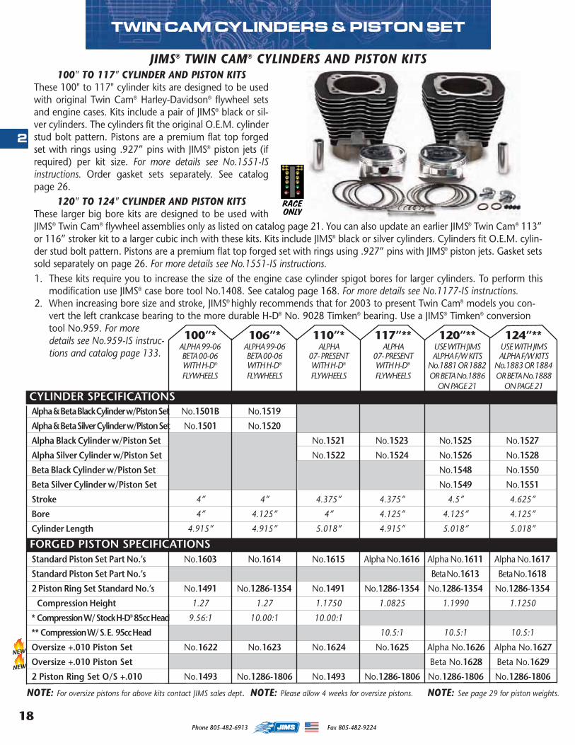
100" TO 117" CYLINDER AND PISTON KITSThese 100" to 117" cylinder kits are designed to be usedwith original Twin Cam® Harley-Davidson® flywheel setsand engine cases. Kits include a pair of JIMS® black or sil-ver cylinders. The cylinders fit the original O.E.M. cylinderstud bolt pattern. Pistons are a premium flat top forgedset with rings using .927” pins with JIMS® piston jets (ifrequired) per kit size. For more details see No.1551-ISinstructions. Order gasket sets separately. See catalogpage 26.
120" TO 124" CYLINDER AND PISTON KITSThese larger big bore kits are designed to be used withJIMS® Twin Cam® flywheel assemblies only as listed on catalog page 21. You can also update an earlier JIMS® Twin Cam® 113”or 116” stroker kit to a larger cubic inch with these kits. Kits include JIMS® black or silver cylinders. Cylinders fit O.E.M. cylin-der stud bolt pattern. Pistons are a premium flat top forged set with rings using .927” pins with JIMS® piston jets. Gasket setssold separately on page 26. For more details see No.1551-IS instructions.1. These kits require you to increase the size of the engine case cylinder spigot bores for larger cylinders. To perform this
modification use JIMS® case bore tool No.1408. See catalog page 168. For more details see No.1177-IS instructions.2. When increasing bore size and stroke, JIMS® highly recommends that for 2003 to present Twin Cam® models you con-
vert the left crankcase bearing to the more durable H-D® No. 9028 Timken® bearing. Use a JIMS® Timken® conversiontool No.959. For moredetails see No.959-IS instruc-tions and catalog page 133.
JIMS® TWIN CAM® CYLINDERS AND PISTON KITS
RACEONLY
100”* 106”* 110”* 117”** 120”** 124”**ALPHA 99-06 ALPHA 99-06 ALPHA ALPHA USE WITH JIMS USE WITH JIMSBETA 00-06 BETA 00-06 07- PRESENT 07- PRESENT ALPHA F/W KITS ALPHA F/W KITSWITH H-D® WITH H-D® WITH H-D® WITH H-D® No.1881 OR 1882 No.1883 OR 1884FLYWHEELS FLYWHEELS FLYWHEELS FLYWHEELS OR BETA No.1886 OR BETA No.1888
ON PAGE 21 ON PAGE 21CYLINDER SPECIFICATIONS
TWIN CAM CYLINDERS & PISTON SET
FORGED PISTON SPECIFICATIONS
NOTE: For oversize pistons for above kits contact JIMS sales dept. NOTE: See page 29 for piston weights.NOTE: Please allow 4 weeks for oversize pistons.
NEW
NEW
MASTER 2013 CATALOG_JMS 2.qxp:Layout 1 8/2/12 8:26 PM Page 18
19
2
Phone 805-482-6913 Fax 805-482-9224
TWIN CAM ® STROKERS
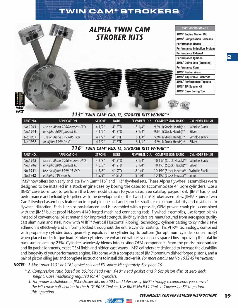
PART NO. APPLICATION STROKE BORE FLYWHEEL DIA. COMPRESSION RATIO CYLINDER FINISH
No.1943 Use on Alpha 2006-present FXD 4 1/2” 4” STD 8 1/4” 9.94:1(Stock Heads)** Wrinkle BlackNo.1944 or Alpha 2007-present FL 4 1/2” 4” STD 8 1/4” 9.94:1(Stock Heads)** Silver
PART NO. APPLICATION STROKE BORE FLYWHEEL DIA. COMPRESSION RATIO CYLINDER FINISH
No.1945 Use on Alpha 2006-present FXD 4 5/8” 4” STD 8 1/4” 10.19:1(Stock Heads)** Wrinkle BlackNo.1946 or Alpha 2007-present FL 4 5/8” 4” STD 8 1/4” 10.19:1(Stock Heads)** Silver
116” TWIN CAM® FXD, FL, STROKER KITS W/VHR™ *
3. For proper installation of JIMS stroker kits on 2003 and later cases, JIMS® strongly recommends you convertthe left crankshaft bearing to the H-D® 9028 Timken. Use JIMS® No.959 Timken Conversion Kit to performthis operation.
**2. Compression ratio based on 85.9cc head with .040” head gasket and 9.5cc piston dish at zero deck height. Case machining required for 4” cylinders.
JIMS® Engine Gasket Kit
JIMS® Compression Releases
Performance Heads
Performance Induction System
Performance Exhaust
Performance Ignition
JIMS® Oiling Jets (Supplied)
Performance Cam
JIMS® Rocker Arms
JIMS® Adjustable Pushrods
JIMS® Performance Tappets
JIMS® EFI Spacer Kit
JIMS® Case Boring Tool
JIMS® RECOMMENDS:
113” TWIN CAM® FXD, FL, STROKER KITS W/VHR™ *
ALPHA TWIN CAMSTROKER KITS
1.Must order 113” or 116” gasket sets and EFI spacer kit separately. See page 26.NOTES:
RACEONLY
JIMS® now offers both early and late Twin Cam® 116” and 113” flywheel sets. These Alpha flywheel assemblies weredesigned to be installed in a stock engine case by boring the cases to accommodate 4” bore cylinders. Use aJIMS® case bore tool to perform the bore modification to your case. See catalog pages 168. JIMS® has joinedperformance and reliability together with the development of the Twin Cam® Stroker assemblies. JIMS® 3-piece TwinCam® flywheel assemblies feature an integral pinion shaft and sprocket shaft for maximum stability and resistance toflywheel distortion. Each kit ships pre-balanced and is assembled with a press-fit, OEM proven crank pin is combinedwith the JIMS® bullet proof H-beam 4140 forged machined connecting rods. Flywheel assemblies, use forged blanksinstead of conventional billet material for improved strength. JIMS® cylinders are manufactured from aerospace qualitycast aluminum and steel. Now with VHR™ (Vertical Horizontal Ribbing) technology, cylinder casting to cylinder sleeveadhesion is effectively and uniformly locked throughout the entire cylinder casting. This VHR™ technology, combinedwith proprietary cylinder body geometry, equalizes the cylinder top to bottom (for optimum cylinder concentricity)when placed under torque load. Stroker cylinders are enhanced with eleven equally spaced fins improving the total finpack surface area by 25%. Cylinders seamlessly blends into existing OEM components. From the precise base surfaceand fin pack alignments, exact OEM finish and hidden cast seams, JIMS® cylinders are designed to increase the durabilityand longevity of your performance engine. Kits come with a compete set of JIMS® premium dished forged pistons, and apair of piston oiling jets and complete instructions to install this stroker kit. For more details see No.1932-IS instructions.
No.1941 Use on Alpha 1999-05 FXD 4 5/8” 4” STD 8 1/4” 10.19:1(Stock Heads)** Wrinkle BlackNo.1942 or Alpha 1999-06 FL 4 5/8” 4” STD 8 1/4” 10.19:1(Stock Heads)** Silver
No.1937 Use on Alpha 1999-05 FXD 4 1/2” 4” STD 8 1/4” 9.94:1(Stock Heads)** Wrinkle BlackNo.1938 or Alpha 1999-06 FL 4 1/2” 4” STD 8 1/4” 9.94:1(Stock Heads)** Silver
SEE JIMSUSA.COM FOR DETAILED INSTRUCTIONS
ights.
MASTER 2013 CATALOG_JMS 2.qxp:Layout 1 8/2/12 8:26 PM Page 19
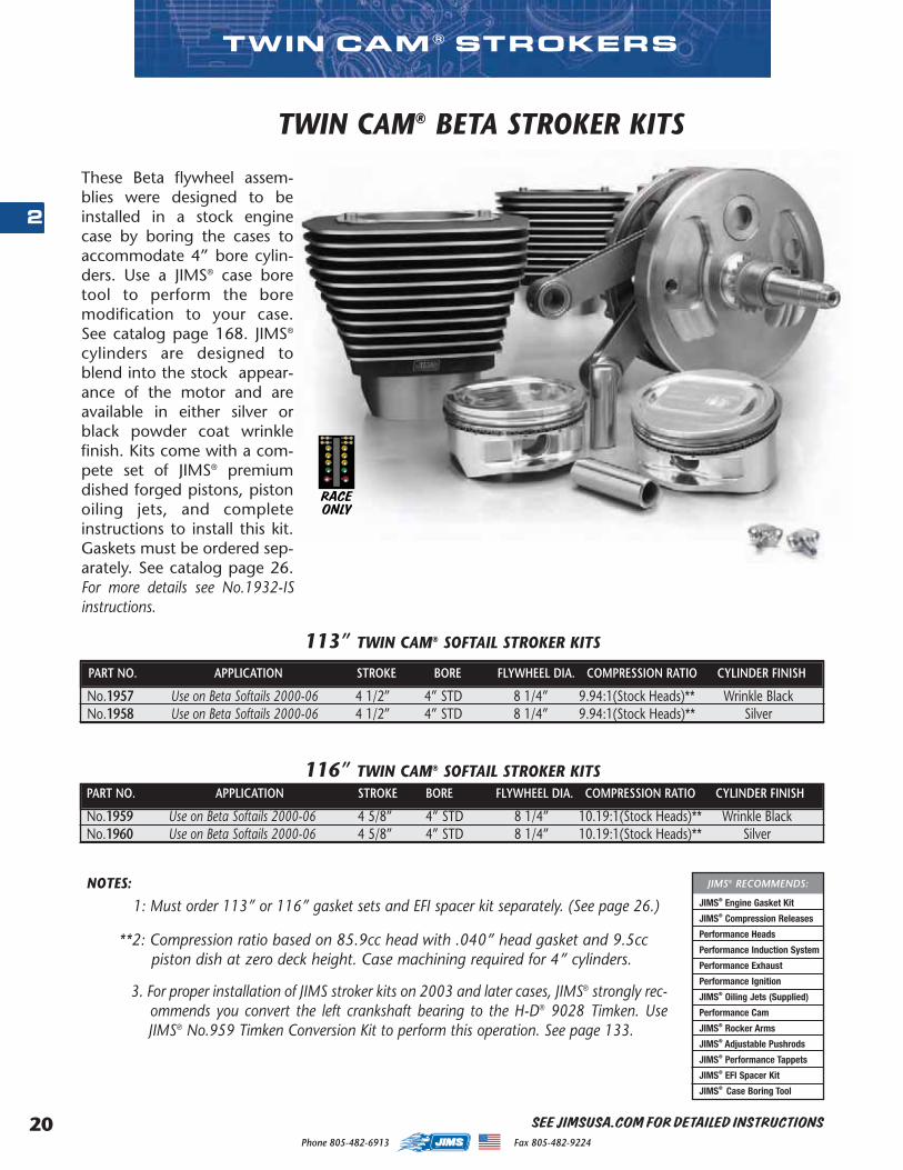
Phone 805-482-6913 Fax 805-482-922420
2
TWIN CAM ® STROKERS
PART NO. APPLICATION STROKE BORE FLYWHEEL DIA. COMPRESSION RATIO CYLINDER FINISH
No.1957 Use on Beta Softails 2000-06 4 1/2” 4” STD 8 1/4” 9.94:1(Stock Heads)** Wrinkle BlackNo.1958 Use on Beta Softails 2000-06 4 1/2” 4” STD 8 1/4” 9.94:1(Stock Heads)** Silver
PART NO. APPLICATION STROKE BORE FLYWHEEL DIA. COMPRESSION RATIO CYLINDER FINISH
No.1959 Use on Beta Softails 2000-06 4 5/8” 4” STD 8 1/4” 10.19:1(Stock Heads)** Wrinkle BlackNo.1960 Use on Beta Softails 2000-06 4 5/8” 4” STD 8 1/4” 10.19:1(Stock Heads)** Silver
113” TWIN CAM® SOFTAIL STROKER KITS
116” TWIN CAM® SOFTAIL STROKER KITS
**2: Compression ratio based on 85.9cc head with .040” head gasket and 9.5ccpiston dish at zero deck height. Case machining required for 4” cylinders.
1: Must order 113” or 116” gasket sets and EFI spacer kit separately. (See page 26.) JIMS® Engine Gasket Kit
JIMS® Compression Releases
Performance Heads
Performance Induction System
Performance Exhaust
Performance Ignition
JIMS® Oiling Jets (Supplied)
Performance Cam
JIMS® Rocker Arms
JIMS® Adjustable Pushrods
JIMS® Performance Tappets
JIMS® EFI Spacer Kit
JIMS® Case Boring Tool
JIMS® RECOMMENDS:NOTES:
3. For proper installation of JIMS stroker kits on 2003 and later cases, JIMS® strongly rec-ommends you convert the left crankshaft bearing to the H-D® 9028 Timken. UseJIMS® No.959 Timken Conversion Kit to perform this operation. See page 133.
These Beta flywheel assem-blies were designed to beinstalled in a stock enginecase by boring the cases toaccommodate 4” bore cylin-ders. Use a JIMS® case boretool to perform the boremodification to your case.See catalog page 168. JIMS®
cylinders are designed toblend into the stock appear-ance of the motor and areavailable in either silver orblack powder coat wrinklefinish. Kits come with a com-pete set of JIMS® premiumdished forged pistons, pistonoiling jets, and completeinstructions to install this kit.Gaskets must be ordered sep-arately. See catalog page 26.For more details see No.1932-ISinstructions.
TWIN CAM® BETA STROKER KITS
RACEONLY
SEE JIMSUSA.COM FOR DETAILED INSTRUCTIONS
MASTER 2013 CATALOG_JMS 2.qxp:Layout 1 8/2/12 8:26 PM Page 20
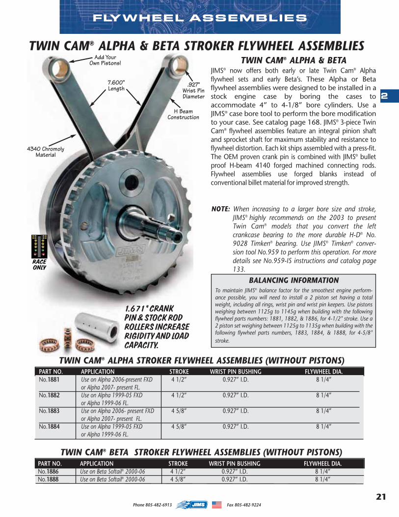
21
2
Phone 805-482-6913 Fax 805-482-9224
TWIN CAM® ALPHA & BETA STROKER FLYWHEEL ASSEMBLIESTWIN CAM® ALPHA & BETA
JIMS® now offers both early or late Twin Cam® Alphaflywheel sets and early Beta’s. These Alpha or Betaflywheel assemblies were designed to be installed in astock engine case by boring the cases toaccommodate 4” to 4-1/8” bore cylinders. Use aJIMS® case bore tool to perform the bore modificationto your case. See catalog page 168. JIMS® 3-piece TwinCam® flywheel assemblies feature an integral pinion shaftand sprocket shaft for maximum stability and resistance toflywheel distortion. Each kit ships assembled with a press-fit.The OEM proven crank pin is combined with JIMS® bulletproof H-beam 4140 forged machined connecting rods.Flywheel assemblies use forged blanks instead ofconventional billet material for improved strength.
4340 ChromolyMaterial
H BeamConstruction
Add YourOwn Pistons!
.927”Wrist PinDiameter
BALANCING INFORMATION To maintain JIMS® balance factor for the smoothest engine perform-ance possible, you will need to install a 2 piston set having a totalweight, including all rings, wrist pin and wrist pin keepers. Use pistonsweighing between 1125g to 1145g when building with the followingflywheel parts numbers: 1881, 1882, & 1886, for 4-1/2" stroke. Use a2 piston set weighing between 1125g to 1135g when building with thefollowing flywheel parts numbers, 1883, 1884, & 1888, for 4-5/8"stroke.
7.600”Length
RACEONLY
FLYWHEEL ASSEMBLIES
TWIN CAM® BETA STROKER FLYWHEEL ASSEMBLIES (WITHOUT PISTONS) PART NO. APPLICATION STROKE WRIST PIN BUSHING FLYWHEEL DIA.No.1886 Use on Beta Softail® 2000-06 4 1/2” 0.927” I.D. 8 1/4”No.1888 Use on Beta Softail® 2000-06 4 5/8” 0.927” I.D. 8 1/4”
NOTE: When increasing to a larger bore size and stroke,JIMS® highly recommends on the 2003 to presentTwin Cam® models that you convert the leftcrankcase bearing to the more durable H-D® No.9028 Timken® bearing. Use JIMS® Timken® conver-sion tool No.959 to perform this operation. For moredetails see No.959-IS instructions and catalog page133.
TWIN CAM® ALPHA STROKER FLYWHEEL ASSEMBLIES (WITHOUT PISTONS)PART NO. APPLICATION STROKE WRIST PIN BUSHING FLYWHEEL DIA.No.1881 Use on Alpha 2006-present FXD 4 1/2” 0.927” I.D. 8 1/4”
or Alpha 2007- present FL.No.1882 Use on Alpha 1999-05 FXD 4 1/2” 0.927” I.D. 8 1/4”
or Alpha 1999-06 FL.No.1883 Use on Alpha 2006- present FXD 4 5/8” 0.927” I.D. 8 1/4”
or Alpha 2007- present FL.No.1884 Use on Alpha 1999-05 FXD 4 5/8” 0.927” I.D. 8 1/4”
or Alpha 1999-06 FL.
1.671” CRANKPIN & STOCK RODROLLERS INCREASERIGIDITY AND LOADCAPACITY.
MASTER 2013 CATALOG_JMS 2.qxp:Layout 1 8/2/12 8:26 PM Page 21
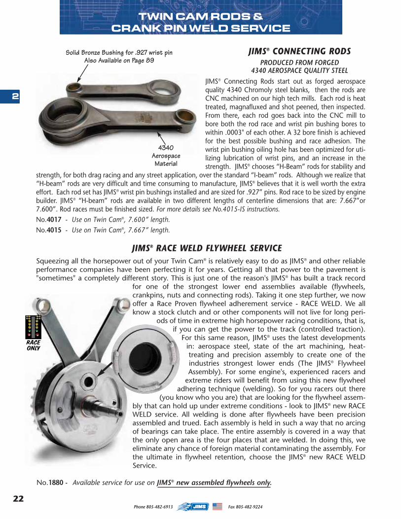
Phone 805-482-6913 Fax 805-482-922422
2
Squeezing all the horsepower out of your Twin Cam® is relatively easy to do as JIMS® and other reliableperformance companies have been perfecting it for years. Getting all that power to the pavement is"sometimes" a completely different story. This is just one of the reason's JIMS® has built a track record
for one of the strongest lower end assemblies available (flywheels,crankpins, nuts and connecting rods). Taking it one step further, we nowoffer a Race Proven flywheel adherement service - RACE WELD. We allknow a stock clutch and or other components will not live for long peri-
ods of time in extreme high horsepower racing conditions, that is,if you can get the power to the track (controlled traction).
For this same reason, JIMS® uses the latest developmentsin: aerospace steel, state of the art machining, heat-treating and precision assembly to create one of theindustries strongest lower ends (The JIMS® FlywheelAssembly). For some engine's, experienced racers and
extreme riders will benefit from using this new flywheeladhering technique (welding). So for you racers out there
(you know who you are) that are looking for the flywheel assem-bly that can hold up under extreme conditions - look to JIMS® new RACEWELD service. All welding is done after flywheels have been precisionassembled and trued. Each assembly is held in such a way that no arcingof bearings can take place. The entire assembly is covered in a way thatthe only open area is the four places that are welded. In doing this, weeliminate any chance of foreign material contaminating the assembly. Forthe ultimate in flywheel retention, choose the JIMS® new RACE WELDService.
No.1880 - Available service for use on JIMS® new assembled flywheels only.
JIMS® Connecting Rods start out as forged aerospacequality 4340 Chromoly steel blanks, then the rods areCNC machined on our high tech mills. Each rod is heattreated, magnafluxed and shot peened, then inspected.From there, each rod goes back into the CNC mill tobore both the rod race and wrist pin bushing bores towithin .0003" of each other. A 32 bore finish is achievedfor the best possible bushing and race adhesion. Thewrist pin bushing oiling hole has been optimized for uti-lizing lubrication of wrist pins, and an increase in thestrength. JIMS® chooses “H-Beam” rods for stability and
strength, for both drag racing and any street application, over the standard “I-beam” rods. Although we realize that“H-beam” rods are very difficult and time consuming to manufacture, JIMS® believes that it is well worth the extraeffort. Each rod set has JIMS® wrist pin bushings installed and are sized for .927” pins. Rod race to be sized by enginebuilder. JIMS® “H-beam” rods are available in two different lengths of centerline dimensions that are: 7.667”or7.600”. Rod races must be finished sized. For more details see No.4015-IS instructions.No.4017 - Use on Twin Cam®, 7.600” length.No.4015 - Use on Twin Cam®, 7.667” length.
4340AerospaceMaterial
Solid Bronze Bushing for .927 wrist pinAlso Available on Page 89
JIMS® CONNECTING RODS PRODUCED FROM FORGED
4340 AEROSPACE QUALITY STEEL
JIMS® RACE WELD FLYWHEEL SERVICE
TWIN CAM RODS & CRANK PIN WELD SERVICE
RACEONLY
MASTER 2013 CATALOG_JMS 2.qxp:Layout 1 8/2/12 8:26 PM Page 22
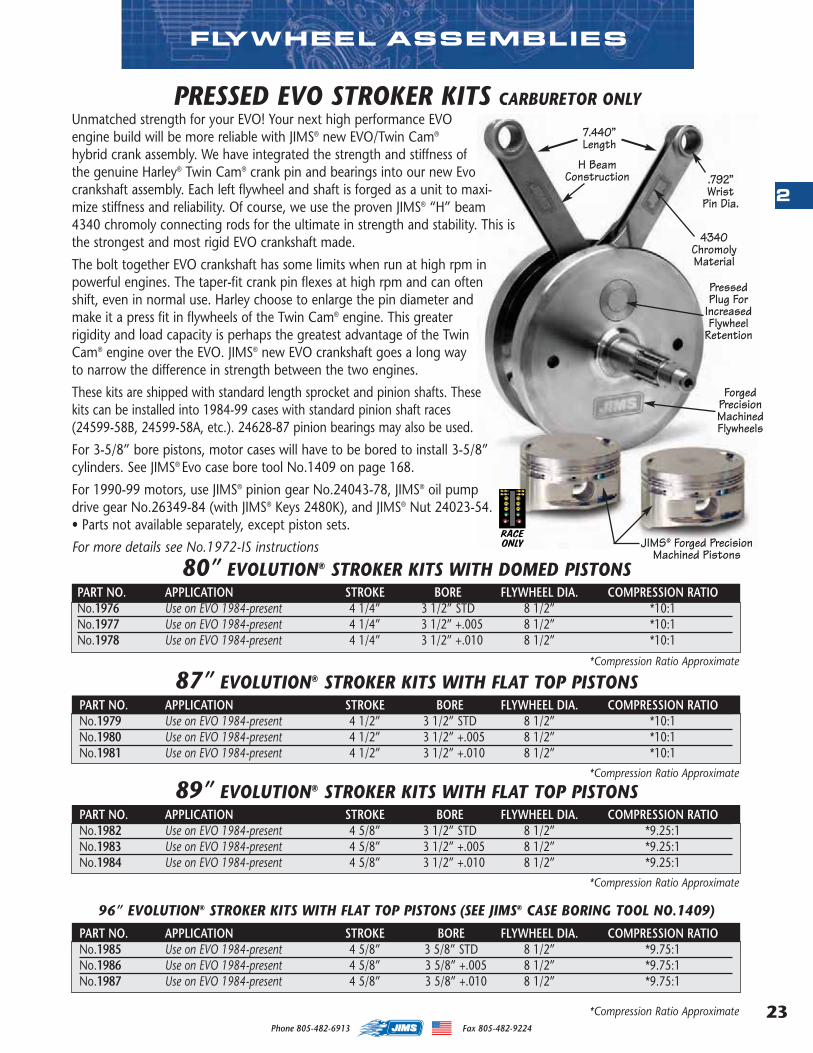
23
2
Phone 805-482-6913 Fax 805-482-9224
FLYWHEEL ASSEMBLIES
89” EVOLUTION® STROKER KITS WITH FLAT TOP PISTONSPART NO. APPLICATION STROKE BORE FLYWHEEL DIA. COMPRESSION RATIONo.1982 Use on EVO 1984-present 4 5/8” 3 1/2” STD 8 1/2” *9.25:1No.1983 Use on EVO 1984-present 4 5/8” 3 1/2” +.005 8 1/2” *9.25:1No.1984 Use on EVO 1984-present 4 5/8” 3 1/2” +.010 8 1/2” *9.25:1
*Compression Ratio Approximate
87” EVOLUTION® STROKER KITS WITH FLAT TOP PISTONSPART NO. APPLICATION STROKE BORE FLYWHEEL DIA. COMPRESSION RATIONo.1979 Use on EVO 1984-present 4 1/2” 3 1/2” STD 8 1/2” *10:1No.1980 Use on EVO 1984-present 4 1/2” 3 1/2” +.005 8 1/2” *10:1No.1981 Use on EVO 1984-present 4 1/2” 3 1/2” +.010 8 1/2” *10:1
*Compression Ratio Approximate
*Compression Ratio Approximate
*Compression Ratio Approximate
4340ChromolyMaterial
.792”Wrist
Pin Dia.
PressedPlug For
IncreasedFlywheel
Retention
ForgedPrecisionMachinedFlywheels
Unmatched strength for your EVO! Your next high performance EVOengine build will be more reliable with JIMS® new EVO/Twin Cam®
hybrid crank assembly. We have integrated the strength and stiffness ofthe genuine Harley® Twin Cam® crank pin and bearings into our new Evocrankshaft assembly. Each left flywheel and shaft is forged as a unit to maxi-mize stiffness and reliability. Of course, we use the proven JIMS® “H” beam4340 chromoly connecting rods for the ultimate in strength and stability. This isthe strongest and most rigid EVO crankshaft made.
The bolt together EVO crankshaft has some limits when run at high rpm inpowerful engines. The taper-fit crank pin flexes at high rpm and can oftenshift, even in normal use. Harley choose to enlarge the pin diameter andmake it a press fit in flywheels of the Twin Cam® engine. This greaterrigidity and load capacity is perhaps the greatest advantage of the TwinCam® engine over the EVO. JIMS® new EVO crankshaft goes a long wayto narrow the difference in strength between the two engines.
These kits are shipped with standard length sprocket and pinion shafts. Thesekits can be installed into 1984-99 cases with standard pinion shaft races(24599-58B, 24599-58A, etc.). 24628-87 pinion bearings may also be used.
For 3-5/8” bore pistons, motor cases will have to be bored to install 3-5/8”cylinders. See JIMS® Evo case bore tool No.1409 on page 168.
For 1990-99 motors, use JIMS® pinion gear No.24043-78, JIMS® oil pumpdrive gear No.26349-84 (with JIMS® Keys 2480K), and JIMS® Nut 24023-54.• Parts not available separately, except piston sets.
For more details see No.1972-IS instructions
7.440”Length
H BeamConstruction
RACEONLY
PRESSED EVO STROKER KITS CARBURETOR ONLY
80” EVOLUTION® STROKER KITS WITH DOMED PISTONSPART NO. APPLICATION STROKE BORE FLYWHEEL DIA. COMPRESSION RATIONo.1976 Use on EVO 1984-present 4 1/4” 3 1/2” STD 8 1/2” *10:1No.1977 Use on EVO 1984-present 4 1/4” 3 1/2” +.005 8 1/2” *10:1No.1978 Use on EVO 1984-present 4 1/4” 3 1/2” +.010 8 1/2” *10:1
JIMS® Forged PrecisionMachined Pistons
96” EVOLUTION® STROKER KITS WITH FLAT TOP PISTONS (SEE JIMS® CASE BORING TOOL NO.1409)
PART NO. APPLICATION STROKE BORE FLYWHEEL DIA. COMPRESSION RATIONo.1985 Use on EVO 1984-present 4 5/8” 3 5/8” STD 8 1/2” *9.75:1No.1986 Use on EVO 1984-present 4 5/8” 3 5/8” +.005 8 1/2” *9.75:1No.1987 Use on EVO 1984-present 4 5/8” 3 5/8” +.010 8 1/2” *9.75:1
MASTER 2013 CATALOG_JMS 2.qxp:Layout 1 8/2/12 8:26 PM Page 23
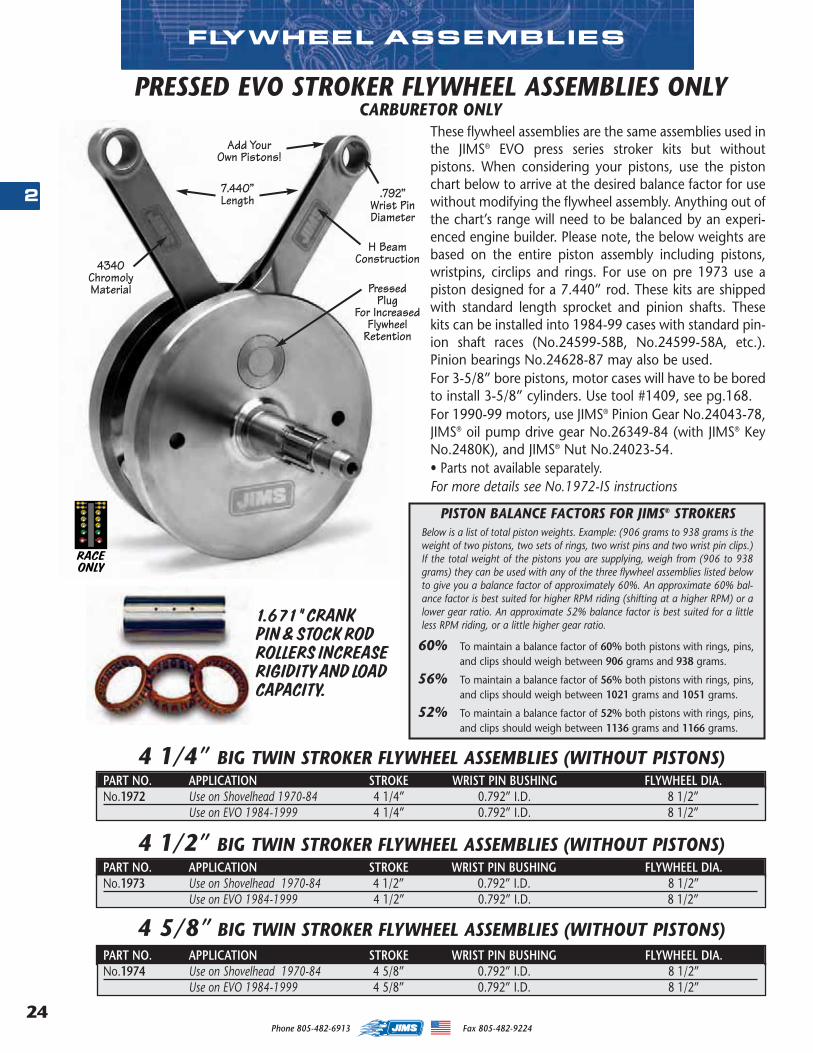
Phone 805-482-6913 Fax 805-482-922424
2
FLYWHEEL ASSEMBLIES
PRESSED EVO STROKER FLYWHEEL ASSEMBLIES ONLY
These flywheel assemblies are the same assemblies used inthe JIMS® EVO press series stroker kits but withoutpistons. When considering your pistons, use the pistonchart below to arrive at the desired balance factor for usewithout modifying the flywheel assembly. Anything out ofthe chart’s range will need to be balanced by an experi-enced engine builder. Please note, the below weights arebased on the entire piston assembly including pistons,wristpins, circlips and rings. For use on pre 1973 use apiston designed for a 7.440” rod. These kits are shippedwith standard length sprocket and pinion shafts. Thesekits can be installed into 1984-99 cases with standard pin-ion shaft races (No.24599-58B, No.24599-58A, etc.).Pinion bearings No.24628-87 may also be used. For 3-5/8” bore pistons, motor cases will have to be boredto install 3-5/8” cylinders. Use tool #1409, see pg.168.For 1990-99 motors, use JIMS® Pinion Gear No.24043-78,JIMS® oil pump drive gear No.26349-84 (with JIMS® KeyNo.2480K), and JIMS® Nut No.24023-54.• Parts not available separately. For more details see No.1972-IS instructions
4 5/8” BIG TWIN STROKER FLYWHEEL ASSEMBLIES (WITHOUT PISTONS) PART NO. APPLICATION STROKE WRIST PIN BUSHING FLYWHEEL DIA.No.1974 Use on Shovelhead 1970-84 4 5/8” 0.792” I.D. 8 1/2”
Use on EVO 1984-1999 4 5/8” 0.792” I.D. 8 1/2”
4 1/2” BIG TWIN STROKER FLYWHEEL ASSEMBLIES (WITHOUT PISTONS)PART NO. APPLICATION STROKE WRIST PIN BUSHING FLYWHEEL DIA.No.1973 Use on Shovelhead 1970-84 4 1/2” 0.792” I.D. 8 1/2”
Use on EVO 1984-1999 4 1/2” 0.792” I.D. 8 1/2”
4 1/4” BIG TWIN STROKER FLYWHEEL ASSEMBLIES (WITHOUT PISTONS)PART NO. APPLICATION STROKE WRIST PIN BUSHING FLYWHEEL DIA.No.1972 Use on Shovelhead 1970-84 4 1/4” 0.792” I.D. 8 1/2”
Use on EVO 1984-1999 4 1/4” 0.792” I.D. 8 1/2”
4340ChromolyMaterial
H BeamConstruction
PressedPlug
For IncreasedFlywheel
Retention
Add YourOwn Pistons!
.792”Wrist PinDiameter
PISTON BALANCE FACTORS FOR JIMS® STROKERS Below is a list of total piston weights. Example: (906 grams to 938 grams is theweight of two pistons, two sets of rings, two wrist pins and two wrist pin clips.)If the total weight of the pistons you are supplying, weigh from (906 to 938grams) they can be used with any of the three flywheel assemblies listed belowto give you a balance factor of approximately 60%. An approximate 60% bal-ance factor is best suited for higher RPM riding (shifting at a higher RPM) or alower gear ratio. An approximate 52% balance factor is best suited for a littleless RPM riding, or a little higher gear ratio.
60% To maintain a balance factor of 60% both pistons with rings, pins,and clips should weigh between 906 grams and 938 grams.
56% To maintain a balance factor of 56% both pistons with rings, pins,and clips should weigh between 1021 grams and 1051 grams.
52% To maintain a balance factor of 52% both pistons with rings, pins,and clips should weigh between 1136 grams and 1166 grams.
CARBURETOR ONLY
7.440”Length
RACEONLY
1.671” CRANKPIN & STOCK RODROLLERS INCREASERIGIDITY AND LOADCAPACITY.
MASTER 2013 CATALOG_JMS 2.qxp:Layout 1 8/2/12 8:26 PM Page 24

25
2
Phone 805-482-6913 Fax 805-482-9224
SALT FLAT RACERS
JODY PEREWITZ:Jody Perewitz and Team J'Witz have exploded into the record books setting a new
land speed record in her rookie season at the Bonneville Salt Flats in 2011. Jody is currently the fastest woman to ever ride anAmerican V-Twin powered motorcycle over 200mph! Jody currently holds 4 land speed records and is looking for more. Her#264 machine is powered by a super strong 100ci V-Twin, boasting cylinders, a flywheel and engine cases from JIMS to helpthis supercharged power plant produce over 230 hp! You can follow Jody onFacebook! HIRO KOISO:
Hiro Koiso is anexpert enginebuilder and per-formance specialistfor a Harley-Davidson dealer. Heis also a multipleAMA National andFIM World LandSpeed records holder! According to Hiro, making record-break-ing horsepower is one thing, but making an engine last isanother story. Hiro Koiso Racing and JIMS became partners in2010, because JIMS components are essential to the treacher-ous racing at Bonneville for both performance and durability.You can also follow Hiro on Facebook!
JIMMY PAULGAARD:Jimmy Paulgaard, from Goldhammer Racing, has been goingto the BUB event at the Bonneville Salt Flats for 4 years now. In2010, Jimmy blew up his engine and looked to be out of theevent when JIMS racer, Hiro Koiso, offered up his JIMS 131”Race Engine. Not only did Hiro, arm sling and all, help bothcrews with the engine switch; Jimmy fired that JIMS engine up
to reset mul-tiple recordshimself. Itwas reallyan amazingsituation,Jimmy fin-ished hisevent with flying colors and Hiro kept his sponsors in the spotlight evenwith a broken bone. Watch for Jimmy to join the 200mph club thisyear!
TR REISER (TMAN):Tom “T.R.” Reiser, owner and operator of T-ManPerformance, has been tearing across the salt for manyyears. In 2010, with a JIMS Fat 5-Speed OverdriveTransmission freshly installed, he snagged the World’sFastest Bagger title at the BUB Speed Trials in Utah with an183.1mph run! T-Man Performance and JIMS have built astrong relationship through our racing experiences and we
are extreme-ly proud tobe a part ofhis team’scontinuedsuccess.Follow T-ManPerformanceonFacebook!
BILL FRANEY:Bill Franey, racing for Salt Wheels Racing, is now in his 6thyear of land speed racing. Bill has been blasting on amotorcycle formuch of his life,and even usedto drag race ondry lakebedsback in the80’s! His crewjust finishedbuilding thisnew landspeed bike, fullyequipped with a JIMS Fat 5-Speed OverdriveTransmission, because it is the toughest, strongest gearboxon the V-Twin market. Cheer Bill on in 2012 as heattempts to break 180mph and set the record in his class!
MASTER 2013 CATALOG_JMS 2.qxp:Layout 1 8/14/12 8:47 PM Page 25
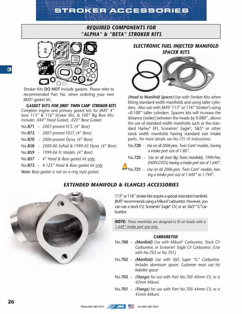
Phone 805-482-6913 Fax 805-482-922426
3
(Head to Manifold Spacer) Use with Stroker Kits whenfitting standard width manifolds and using taller cylin-ders. Also use with JIMS® 113” or 116” Stroker’s using+0.100” taller cylinders. Spacers kits will increase thedistance (wider) between the heads by 0.080”, allowsthe use of standard width manifolds such as the stan-dard Harley® EFI, Screamin’ Eagle®, S&S® or otherstock width manifolds having standard size intakeports. For more details see No.721-IS instructions.
No.720 - Use on all 2006-pres. Twin Cam® models, havinga intake port size of 1.80”.
No.725 - Use on all stock Big Twins manifolds, 1990-Pres.(NON-CVO’s) having a intake port size of 1.640”.
No.721 - Use on all 2006-pres. Twin Cam® models, hav-ing a intake port size of 1.640” to 1.740”.
EXTENDED MANIFOLD & FLANGES ACCESSORIES
NOTE: These manifolds are designed to fit on heads with a1.640” intake port size only.
CARBURETEDNo.700 - (Manifold) Use with Mikuni® Carburetor, Stock CV
Carburetor, or Screamin’ Eagle CV Carburetor. (Usewith No.703 or No.701)
No.702 - (Manifold) Use with S&S Super “G” Carburetor.Includes aluminum spacer. Customer must use hisbakelite spacer
No.703 - (Flange) for use with Part No.700 40mm CV, or a42mm Mikuni.
No.701 - (Flange) for use with Part No.700 44mm CV, or a45mm Mikuni.
STROKER ACCESSORIES
Stroker Kits DO NOT include gaskets. Please refer torecommended Part No. when ordering your newJIMS® gasket kit.
GASKET KITS FOR JIMS® TWIN CAM® STROKER KITSComplete engine and primary gasket kits for JIMS® 4”bore 113” & 116” Stroker Kits, & 100” Big Bore Kits.Includes .040” Head Gasket, .020” Base Gasket.No.871 - 2007-present FL’S. (4” Bore)No.872 - 2007-present FXST. (4” Bore)No.870 - 2006-present Dyna. (4” Bore)No.858 - 2000-06 Softail & 1999-05 Dyna. (4” Bore)No.859 - 1999-06 FL Models. (4” Bore)No.857 - 4” Head & Base gasket kit only. No.873 - 4.125” Head & Base gasket kit only. Note: Base gasket is not an o-ring style gasket.
REQUIRED COMPONENTS FOR“ALPHA” & “BETA” STROKER KITS
113” or 116” stroker kits require a special extended manifold.JIMS® recommends using a Mikuni®carburetor. However, youcan use a stock CV, Screamin’ Eagle® CV, or an S&S® “G”car-buretor.
ELECTRONIC FUEL INJECTED MANIFOLDSPACER KITS
NEW
MASTER 2013 CATALOG_JMS 2.qxp:Layout 1 8/2/12 8:26 PM Page 26
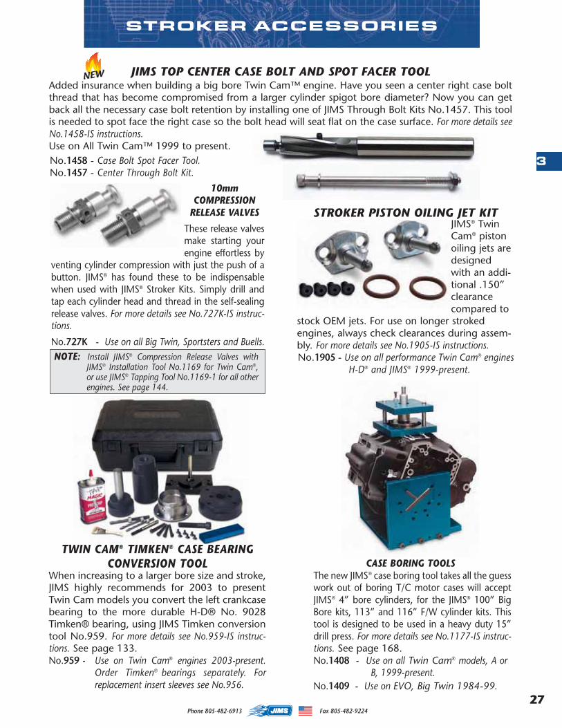
27
3
Phone 805-482-6913 Fax 805-482-9224
CASE BORING TOOLSThe new JIMS® case boring tool takes all the guesswork out of boring T/C motor cases will acceptJIMS® 4” bore cylinders, for the JIMS® 100” BigBore kits, 113” and 116” F/W cylinder kits. Thistool is designed to be used in a heavy duty 15”drill press. For more details see No.1177-IS instruc-tions. See page 168.No.1408 - Use on all Twin Cam® models, A or
B, 1999-present.No.1409 - Use on EVO, Big Twin 1984-99.
STROKER ACCESSORIES
STROKER PISTON OILING JET KITJIMS® TwinCam® pistonoiling jets aredesignedwith an addi-tional .150”clearancecompared to
stock OEM jets. For use on longer strokedengines, always check clearances during assem-bly. For more details see No.1905-IS instructions.No.1905 - Use on all performance Twin Cam® engines
H-D® and JIMS® 1999-present.
TWIN CAM® TIMKEN® CASE BEARINGCONVERSION TOOL
When increasing to a larger bore size and stroke,JIMS highly recommends for 2003 to presentTwin Cam models you convert the left crankcasebearing to the more durable H-D® No. 9028Timken® bearing, using JIMS Timken conversiontool No.959. For more details see No.959-IS instruc-tions. See page 133.No.959 - Use on Twin Cam® engines 2003-present.
Order Timken® bearings separately. Forreplacement insert sleeves see No.956.
10mmCOMPRESSION
RELEASE VALVES
These release valvesmake starting yourengine effortless by
venting cylinder compression with just the push of abutton. JIMS® has found these to be indispensablewhen used with JIMS® Stroker Kits. Simply drill andtap each cylinder head and thread in the self-sealingrelease valves. For more details see No.727K-IS instruc-tions.
No.727K - Use on all Big Twin, Sportsters and Buells.NOTE: Install JIMS® Compression Release Valves with
JIMS® Installation Tool No.1169 for Twin Cam®,or use JIMS® Tapping Tool No.1169-1 for all otherengines. See page 144.
JIMS TOP CENTER CASE BOLT AND SPOT FACER TOOLAdded insurance when building a big bore Twin Cam™ engine. Have you seen a center right case boltthread that has become compromised from a larger cylinder spigot bore diameter? Now you can getback all the necessary case bolt retention by installing one of JIMS Through Bolt Kits No.1457. This toolis needed to spot face the right case so the bolt head will seat flat on the case surface. For more details seeNo.1458-IS instructions.Use on All Twin Cam™ 1999 to present.No.1458 - Case Bolt Spot Facer Tool.No.1457 - Center Through Bolt Kit.
NEW
MASTER 2013 CATALOG_JMS 2.qxp:Layout 1 8/2/12 8:26 PM Page 27

Phone 805-482-6913 Fax 805-482-922428
4
DAYTONA TWIN TEC IGNITIONMODULES
These carburetedDaytona Twin Tecadjustable mod-ule’s, features are:
• Wide timing advance adjustment rangethat accommodates stock to highly modi-fied engines.
• Digitally set RPM limit (steps from 3,000 to9,900 RPM).
• Full support for J1850 data bus used forcommunications with instrument clusterand turn signal / security module(TSM/TSSM).
• Compatible with aftermarket tachometers.• Built – in data logging. Stores last 30 min-
utes of engine operation. • Extensive diagnostics and compatibility
with H-D scan tool. • Optional UBS interface and software for cus-
tom programming and data analysis.• Billet housing with a 12 pin connector.• Easy plug in installation with instructions.
No. 2228 - Use on carbureted 2003-2006 Twin Camand Sportster. Also for 2004-2007American Iron Horse motorcycles.
These carbureted Daytona Twin Tec adjustablemodule’s, features are: • Wide range of timing advance adjustment
that accommodates stock to highly modi-fied engines.
• Digitally set RPM limit (100 RPM steps).• Selectable multi – spark mode for quick
starting and smooth cruise. • Coil outputs protected against short circuits. • Optional UBS interface and software for
programming custom advance curve.• Billet housing with a 12 pin connector. • Supports all sensors including theft/security
module. • Easy plug in installation with instructions.No. 2229 - Use on 1999 -2003 carbureted Twin Cam
models.
These carbureted Daytona Twin Tec adjustablemodule’s, features are: • Wide range timing advance adjustment
accommodates stock to highly modifiedengines.
• Digitally set RPM limit (100 RPM steps).• Selectable multi – spark mode for quick start-
ing and smooth cruise. • Coil outputs protected against short circuits. • Optional UBS interface and software for pro-
gramming custom advance curve.• Billet housing with a 8 pin connector. • Easy plug in installation with instructions.No. 2230 - Use on 1994 - 1999 later Evolution Big
Twins.
This accessory interfaces with all Daytona TwinTech engine ignition controls. Windows com-patible software allows the UPC to program acustom advance curve for precise dyno tuning.Includes all required adapters for Models 1005 -1007, TC88, TC88A ignitions, and TCFI/VRF1fuel injection systems.
No. 2231 - Use on JIMS No. 2228, 2229, or 2230modules and TCFI/VRF1 fuel injectionsystems.
NEWNEW
NEW
NEW
USB CABLE INTERFACE
PLUG IN 12 PINIGNITION MODULE
PLUG IN DUEL 6 PIN IGNITION MODULE
EXTERNAL PLUG IGNITION MODULE
*
*
**
Note: For any technical support on the modules contact: Daytona Twin Tech 1-386-304-0700.*
MASTER 2013 CATALOG_JMS 2.qxp:Layout 1 8/2/12 8:26 PM Page 28
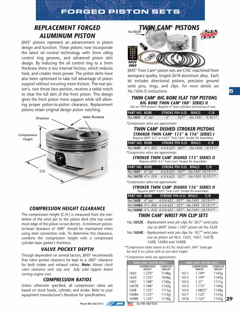
29
5
FORGED PISTON SETS
JIMS® Twin Cam® piston sets are CNC machined fromaerospace quality, forged 2618 aluminum alloy. Eachkit includes directional pistons, precision groundwrist pins, rings, and clips. For more details seeNo.1606-IS instructions.
BIG BORE TWIN CAM® 100” SERIES IIUse on 1999-present. Requires 4” bore cylinders and boring of case.
PART NO. BORE STROKE PIN O.D. RINGS C/RNo.1603 4” std 4” .927” No.1491 9.56:1*
STROKER TWIN CAM® DISHED 113” SERIES IIRequires JIMS® 4.5” Twin Cam® Stroker Kit Assemblies
PART NO. BORE STROKE PIN O.D. RINGS C/RNo.1607 4” std 4.5/4.625 .927” No.1491 10.19:1**No.1607B 4”+ .010 4.5/4.625 .927” No.1493 10.19:1**
STROKER TWIN CAM® DISHED 116” SERIES IIRequires JIMS® 4.625” Twin Cam® Stroker Kit Assemblies
PART NO. BORE STROKE PIN O.D. RINGS C/RNo.1608 4” std 4.5/4.625 .927” No.1491 10.19:1**No.1608A 4”+ .005 4.5/4.625 .927” No.1492 10.19:1**No.1608B 4”+ .010 4.5/4.625 .927” No.1493 10.19:1**
STROKER TWIN CAM® 113” & 116” SERIES IRequires JIMS® 4.5” or 4.625” Twin Cam® Stroker Kit Assemblies
PART NO. BORE STROKE PIN O.D. RINGS C/RNo.1620 4”+ .005 4.5/4.625 .827” No.1428 10.19:1*
JIMS® pistons represent an advancement in pistondesign and function. These pistons now incorporatethe latest oil control technology with 3mm oilingcontrol ring grooves, and advanced piston skirtdesign. By reducing the oil control ring to a 3mmthickness there is less internal friction, which reducesheat, and creates more power. The piston skirts havealso been optimized to take full advantage of pistonsupport without incurring more friction. The rear pis-ton’s, non thrust face portion, receives a radial notchto clear the full skirt of the front piston. This designgives the front piston more support while still allow-ing proper piston-to-piston clearance. Replacementpistons retain original design piston notching.
REPLACEMENT FORGEDALUMINUM PISTON
TWIN CAM® BIG BORE FLAT TOP PISTONS
TWIN CAM® DISHED STROKER PISTONS
**Compression ratios based on 85.9cc head with .040” head gasket and 9.5cc piston dish at zero deck height.
*Compression ratios are approximate.
*Compression ratios are approximate.
*Compression ratios are approximate.
*Compression ratios are approximate.
The compression height (C.H.) is measured from the cen-terline of the wrist pin to the piston deck (the top outermost edge of the piston w/out dome). A minimum piston-to-head clearance of .040” should be maintained whenusing steel connection rods. To determine this clearance,combine the compression height with a compressedcylinder base gasket’s thickness.
COMPRESSION HEIGHT CLEARANCE
Though dependent on several factors, JIMS® recommendsthat valve pocket clearance be kept to a .060” clearancefor both intake and exhaust valves. Note: Always checkvalve clearance with clay and fully solid tappets beforeturning engine over.
VALVE POCKET DEPTH
CompressionHeight
Valve PocketsDirection
O.D.
Unless otherwise specified, all compression ratios arebased on stock heads, cylinder, and stroke. Refer to yourequipment manufacturer’s literature for specifications.
COMPRESSION RATIOS1603 1.270” 1148g1620 1.125” 1058g1607 1.188” 1140g1607B 1.188” 1142g1608 1.125” 1115g1608A 1.125” 1116g1608B 1.125” 1118g
COMPRESSIONHEIGHT
COMPLETEWEIGHT
TWIN CAM® PISTON SPECS.
RACEONLY
TWIN CAM® WRIST PIN CLIP SETSNo.1602K - Replacement wrist pin clips for .827” wrist pins.
Use on JIMS® Series I 100” piston set No.1620.No.1604K - Replacement wrist pin clips for .927” wrist pins.
Use on piston set No’s. 1603, 1607, 1607B, 1608, 1608A and 1608B.
TWIN CAM® PISTONS
1611 1.199” 1145g1613 1.199” 1149g1614 1.27” 1171g1615 1.175” 1149g1616 1.0825” 1148g1617 1.125” 1143g1618 1.125” 1145g
COMPRESSIONHEIGHT
COMPLETEWEIGHT
TWIN CAM® PISTON SPECS.
No.1608
Phone 805-482-6913 Fax 805-482-9224
MASTER 2013 CATALOG_JMS 2.qxp:Layout 1 8/2/12 8:26 PM Page 29
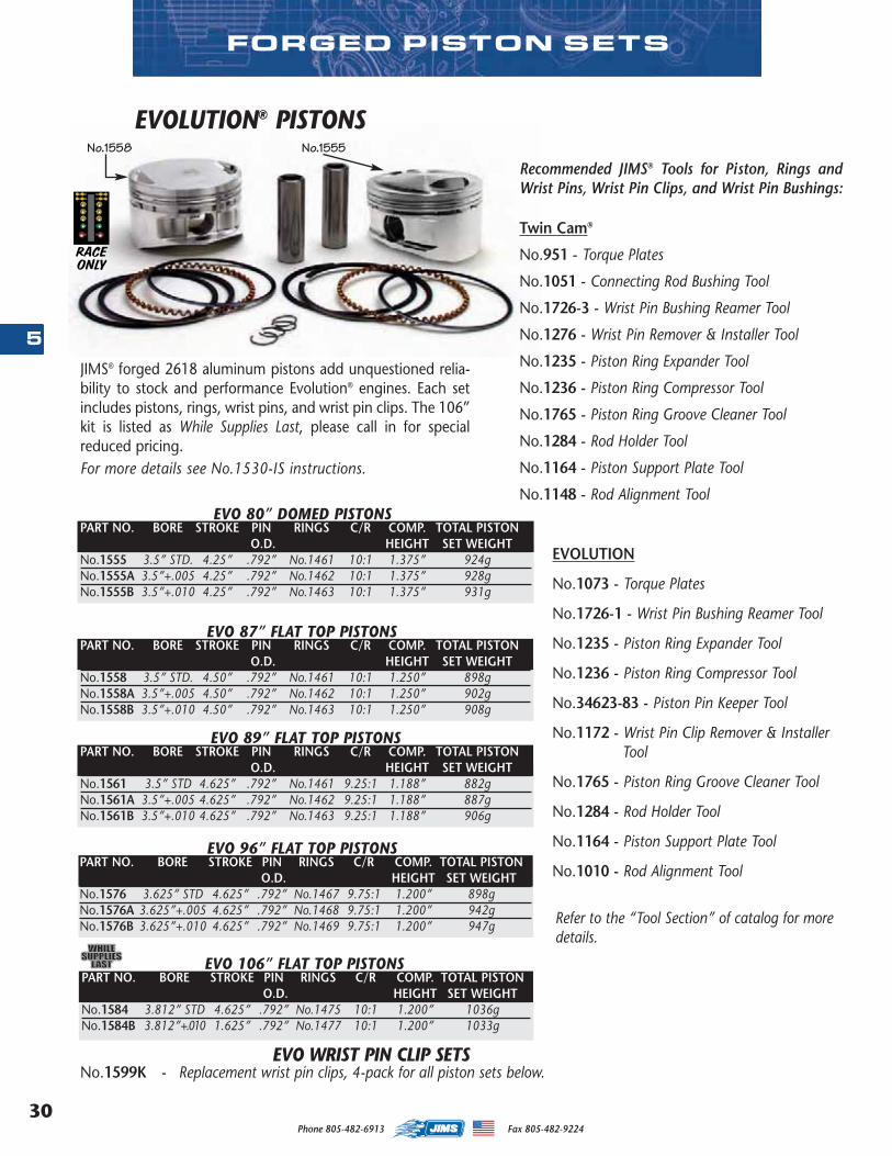
Phone 805-482-6913 Fax 805-482-922430
5
FORGED PISTON SETS
EVOLUTION® PISTONS
JIMS® forged 2618 aluminum pistons add unquestioned relia-bility to stock and performance Evolution® engines. Each setincludes pistons, rings, wrist pins, and wrist pin clips. The 106”kit is listed as While Supplies Last, please call in for specialreduced pricing.For more details see No.1530-IS instructions.
Recommended JIMS® Tools for Piston, Rings andWrist Pins, Wrist Pin Clips, and Wrist Pin Bushings:
Twin Cam®
No.951 - Torque Plates
No.1051 - Connecting Rod Bushing Tool
No.1726-3 - Wrist Pin Bushing Reamer Tool
No.1276 - Wrist Pin Remover & Installer Tool
No.1235 - Piston Ring Expander Tool
No.1236 - Piston Ring Compressor Tool
No.1765 - Piston Ring Groove Cleaner Tool
No.1284 - Rod Holder Tool
No.1164 - Piston Support Plate Tool
No.1148 - Rod Alignment Tool
EVOLUTION
No.1073 - Torque Plates
No.1726-1 - Wrist Pin Bushing Reamer Tool
No.1235 - Piston Ring Expander Tool
No.1236 - Piston Ring Compressor Tool
No.34623-83 - Piston Pin Keeper Tool
No.1172 - Wrist Pin Clip Remover & InstallerTool
No.1765 - Piston Ring Groove Cleaner Tool
No.1284 - Rod Holder Tool
No.1164 - Piston Support Plate Tool
No.1010 - Rod Alignment Tool
Refer to the “Tool Section” of catalog for moredetails.
RACEONLY
EVO WRIST PIN CLIP SETSNo.1599K - Replacement wrist pin clips, 4-pack for all piston sets below.
PART NO. BORE STROKE PIN RINGS C/R COMP. TOTAL PISTONO.D. HEIGHT SET WEIGHT
No.1558 3.5” STD. 4.50” .792” No.1461 10:1 1.250” 898gNo.1558A 3.5”+.005 4.50” .792” No.1462 10:1 1.250” 902gNo.1558B 3.5”+.010 4.50” .792” No.1463 10:1 1.250” 908g
EVO 87” FLAT TOP PISTONS
PART NO. BORE STROKE PIN RINGS C/R COMP. TOTAL PISTONO.D. HEIGHT SET WEIGHT
No.1561 3.5” STD 4.625” .792” No.1461 9.25:1 1.188” 882gNo.1561A 3.5”+.005 4.625” .792” No.1462 9.25:1 1.188” 887gNo.1561B 3.5”+.010 4.625” .792” No.1463 9.25:1 1.188” 906g
EVO 89” FLAT TOP PISTONS
PART NO. BORE STROKE PIN RINGS C/R COMP. TOTAL PISTONO.D. HEIGHT SET WEIGHT
No.1576 3.625” STD 4.625” .792” No.1467 9.75:1 1.200” 898gNo.1576A 3.625”+.005 4.625” .792” No.1468 9.75:1 1.200” 942gNo.1576B 3.625”+.010 4.625” .792” No.1469 9.75:1 1.200” 947g
EVO 96” FLAT TOP PISTONS
PART NO. BORE STROKE PIN RINGS C/R COMP. TOTAL PISTONO.D. HEIGHT SET WEIGHT
No.1584 3.812” STD 4.625” .792” No.1475 10:1 1.200” 1036gNo.1584B 3.812”+.010 1.625” .792” No.1477 10:1 1.200” 1033g
EVO 106” FLAT TOP PISTONS
PART NO. BORE STROKE PIN RINGS C/R COMP. TOTAL PISTONO.D. HEIGHT SET WEIGHT
No.1555 3.5” STD. 4.25” .792” No.1461 10:1 1.375” 924gNo.1555A 3.5”+.005 4.25” .792” No.1462 10:1 1.375” 928gNo.1555B 3.5”+.010 4.25” .792” No.1463 10:1 1.375” 931g
EVO 80” DOMED PISTONS
No.1558 No.1555
MASTER 2013 CATALOG_JMS 2.qxp:Layout 1 8/2/12 8:26 PM Page 30
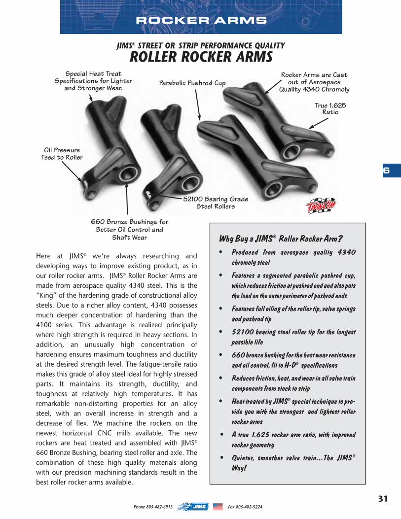
31
6
Phone 805-482-6913 Fax 805-482-9224
JIMS® STREET OR STRIP PERFORMANCE QUALITY
ROLLER ROCKER ARMS
Why Buy a JIMS® Roller Rocker Arm?• Produced from aerospace quality 4340
chromoly steel
• Features a segmented parabolic pushrod cup,which reduces friction at pushrod end and also putsthe load on the outer perimeter of pushrod ends
• Features full oiling of the roller tip, valve springsand pushrod tip
• 52100 bearing steel roller tip for the longestpossible life
• 660 bronze bushing for the best wear resistanceand oil control, fit to H-D® specifications
• Reduces friction, heat, and wear in all valve traincomponents from stock to strip
• Heat treated by JIMS® special technique to pro-vide you with the strongest and lightest rollerrocker arms
• A true 1.625 rocker arm ratio, with improvedrocker geometry
• Quieter, smoother valve train...The JIMS®
Way!
ROCKER ARMS
Rocker Arms are Castout of Aerospace
Quality 4340 Chromoly
True 1.625 Ratio
660 Bronze Bushings forBetter Oil Control and
Shaft Wear
Parabolic Pushrod Cup
52100 Bearing GradeSteel Rollers
Oil Pressure Feed to Roller
Special Heat TreatSpecifications for Lighter
and Stronger Wear.
Here at JIMS® we’re always researching anddeveloping ways to improve existing product, as inour roller rocker arms. JIMS® Roller Rocker Arms aremade from aerospace quality 4340 steel. This is the“King” of the hardening grade of constructional alloysteels. Due to a richer alloy content, 4340 possessesmuch deeper concentration of hardening than the4100 series. This advantage is realized principallywhere high strength is required in heavy sections. Inaddition, an unusually high concentration ofhardening ensures maximum toughness and ductilityat the desired strength level. The fatigue-tensile ratiomakes this grade of alloy steel ideal for highly stressedparts. It maintains its strength, ductility, andtoughness at relatively high temperatures. It hasremarkable non-distorting properties for an alloysteel, with an overall increase in strength and adecrease of flex. We machine the rockers on thenewest horizontal CNC mills available. The newrockers are heat treated and assembled with JIMS®
660 Bronze Bushing, bearing steel roller and axle. Thecombination of these high quality materials alongwith our precision machining standards result in thebest roller rocker arms available.
MASTER 2013 CATALOG_JMS 2.qxp:Layout 1 8/2/12 8:26 PM Page 31
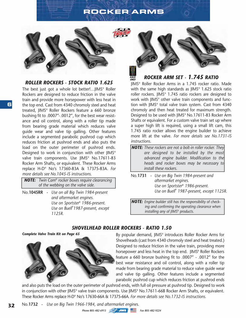
Phone 805-482-6913 Fax 805-482-922432
6
ROLLER ROCKERS - STOCK RATIO 1.625The best just got a whole lot better!…JIMS® RollerRockers are designed to reduce friction in the valvetrain and provide more horsepower with less heat inthe top end. Cast from 4340 chromoly steel and heattreated, JIMS® Roller Rockers feature a 660 bronzebushing fit to .0007”- .0012”, for the best wear resist-ance and oil control, along with a roller tip madefrom bearing grade material which reduces valveguide wear and valve tip galling. Other featuresinclude a segmented parabolic pushrod cup whichreduces friction at pushrod ends and also puts theload on the outer perimeter of pushrod ends.Designed to work in conjunction with other JIMS®
valve train components. Use JIMS® No.17611-83Rocker Arm Shafts, or equivalent. These Rocker Armsreplace H-D® No’s 17360-83A & 17375-83A. Formore details see No.1045-IS instructions.
No.1045RR - Use on all Big Twin 1984-presentand aftermarket engines.Use on Sportster® 1986-present.Use on Buell®1987-present, except 1125R.
ROCKER ARM SET - 1.745 RATIOJIMS® Roller Rocker Arms in a 1.745 rocker ratio. Madewith the same high standards as JIMS® 1.625 stock ratioroller rockers. JIMS® 1.745 ratio rockers are designed towork with JIMS® other valve train components and func-tion with JIMS® total valve train system. Cast from 4340chromoly and then heat treated for maximum strength.Designed to be used with JIMS® No.17611-83 Rocker ArmShafts or equivalent. For a custom valve train set up wherea super high lift is required, using a small lift cam, this1.745 ratio rocker allows the engine builder to achievemore lift at the valve. For more details see No.1731-ISinstructions.
No.1731 - Use on Big Twin 1984-present and aftermarket engines.Use on Sportster® 1986-present. Use on Buell® 1987-present, except 1125R.
ROCKER ARMS
By popular demand, JIMS® introduces Roller Rocker Arms forShovelheads (cast from 4340 chromoly steel and heat treated.)Designed to reduce friction in the valve train, providing morehorsepower and less heat in the top end. JIMS® Roller Rockersfeature a 660 bronze bushing fit to .0007” - .0012” for thebest wear resistance and oil control, along with a roller tipmade from bearing grade material to reduce valve guide wearand valve tip galling. Other features include a segmentedparabolic pushrod cup which reduces friction at pushrod ends
and also puts the load on the outer perimeter of pushrod ends, with full oil pressure at pushrod tip. Designed to workin conjunction with other JIMS® valve train components. Use JIMS® No.17611-66B Rocker Arm Shafts, or equivalent.These Rocker Arms replace H-D® No’s 17630-66A & 17375-66A. For more details see No.1732-IS instructions.
No.1732 - Use on Big Twin 1966-1984, and aftermarket engines.
SHOVELHEAD ROLLER ROCKERS - RATIO 1.50
NOTE: Engine builder still has the responsibility of check-ing and confirming the operating clearance wheninstalling any of JIMS® products.
Complete Valve Train Kit on Page 65
NOTE: These rockers are not a bolt-in roller rocker. Theyare designed to be installed by the mostadvanced engine builder. Modification to theheads and rocker boxes may be necessary toinstall these rockers.
RACEONLY
NOTE: Twin Cam® rocker boxes require clearancingof the webbing on the valve side.
MASTER 2013 CATALOG_JMS 2.qxp:Layout 1 8/2/12 8:26 PM Page 32
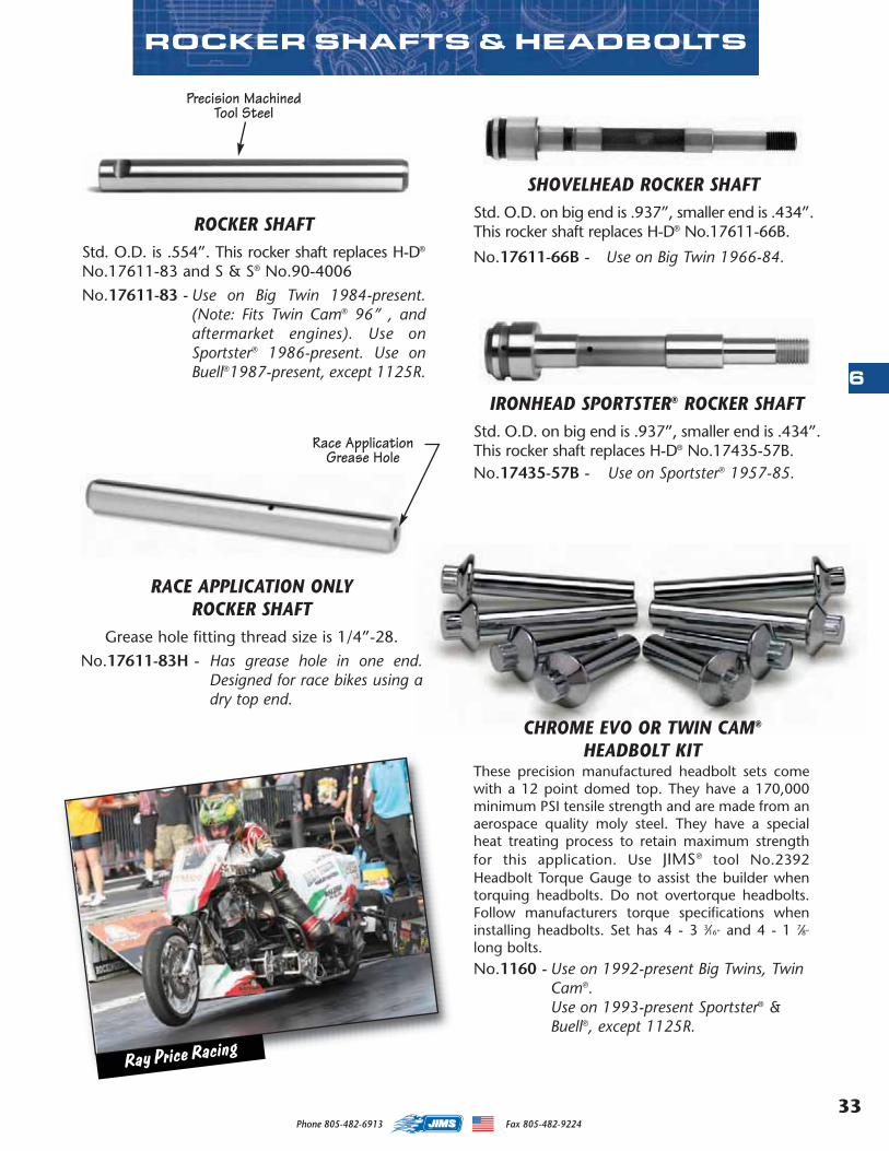
33
6
Phone 805-482-6913 Fax 805-482-9224
SHOVELHEAD ROCKER SHAFTStd. O.D. on big end is .937”, smaller end is .434”.This rocker shaft replaces H-D® No.17611-66B.
No.17611-66B - Use on Big Twin 1966-84.
ROCKER SHAFTStd. O.D. is .554”. This rocker shaft replaces H-D®
No.17611-83 and S & S® No.90-4006
No.17611-83 - Use on Big Twin 1984-present.(Note: Fits Twin Cam® 96” , andaftermarket engines). Use onSportster® 1986-present. Use onBuell®1987-present, except 1125R.
RACE APPLICATION ONLYROCKER SHAFT
Grease hole fitting thread size is 1/4”-28.
No.17611-83H - Has grease hole in one end.Designed for race bikes using adry top end.
IRONHEAD SPORTSTER® ROCKER SHAFTStd. O.D. on big end is .937”, smaller end is .434”.This rocker shaft replaces H-D® No.17435-57B.No.17435-57B - Use on Sportster® 1957-85.
ROCKER SHAFTS & HEADBOLTS
Precision MachinedTool Steel
Race ApplicationGrease Hole
CHROME EVO OR TWIN CAM®
HEADBOLT KITThese precision manufactured headbolt sets comewith a 12 point domed top. They have a 170,000minimum PSI tensile strength and are made from anaerospace quality moly steel. They have a specialheat treating process to retain maximum strengthfor this application. Use JIMS® tool No.2392Headbolt Torque Gauge to assist the builder whentorquing headbolts. Do not overtorque headbolts.Follow manufacturers torque specifications wheninstalling headbolts. Set has 4 - 3 3⁄16” and 4 - 1 7⁄8”
long bolts.No.1160 - Use on 1992-present Big Twins, Twin
Cam®.Use on 1993-present Sportster® &Buell®, except 1125R.
Ray Price Racing
MASTER 2013 CATALOG_JMS 2.qxp:Layout 1 8/2/12 8:26 PM Page 33
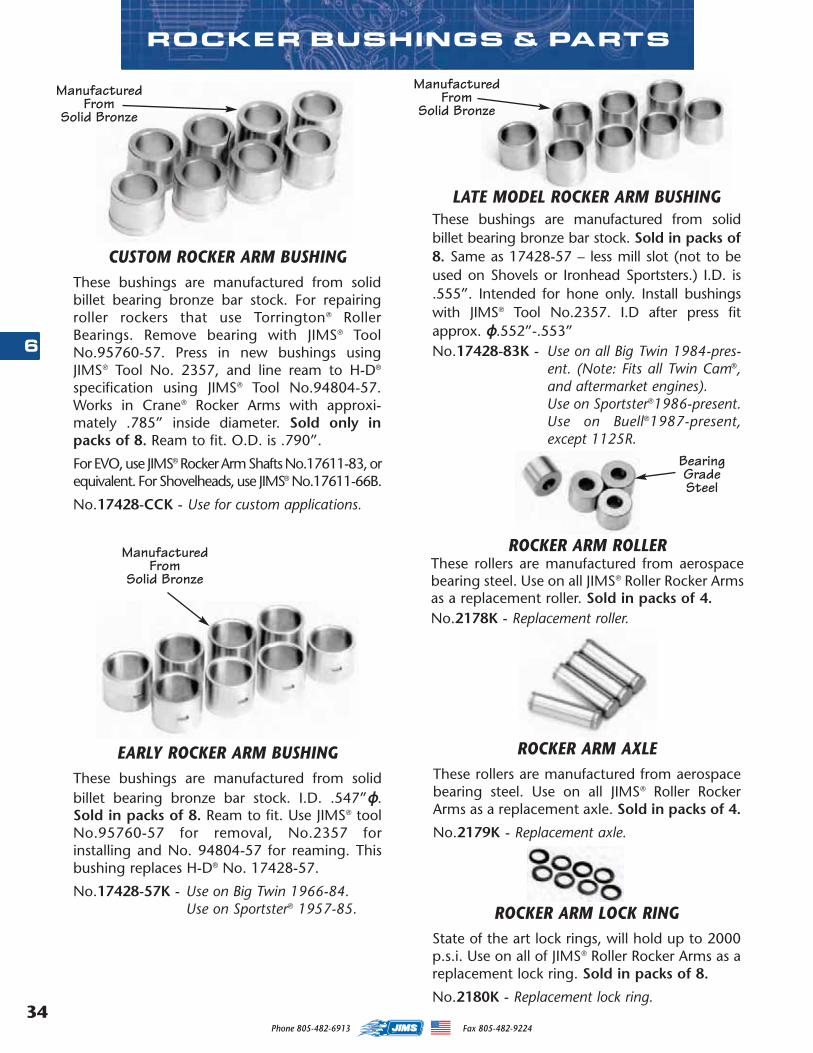
Phone 805-482-6913 Fax 805-482-922434
6
CUSTOM ROCKER ARM BUSHINGThese bushings are manufactured from solidbillet bearing bronze bar stock. For repairingroller rockers that use Torrington® RollerBearings. Remove bearing with JIMS® ToolNo.95760-57. Press in new bushings usingJIMS® Tool No. 2357, and line ream to H-D®
specification using JIMS® Tool No.94804-57.Works in Crane® Rocker Arms with approxi-mately .785” inside diameter. Sold only inpacks of 8. Ream to fit. O.D. is .790”.
For EVO, use JIMS® Rocker Arm Shafts No.17611-83, orequivalent. For Shovelheads, use JIMS® No.17611-66B.
No.17428-CCK - Use for custom applications.
LATE MODEL ROCKER ARM BUSHINGThese bushings are manufactured from solidbillet bearing bronze bar stock. Sold in packs of8. Same as 17428-57 – less mill slot (not to beused on Shovels or Ironhead Sportsters.) I.D. is.555”. Intended for hone only. Install bushingswith JIMS® Tool No.2357. I.D after press fitapprox. ɸ.552”-.553”No.17428-83K - Use on all Big Twin 1984-pres-
ent. (Note: Fits all Twin Cam®,and aftermarket engines).Use on Sportster®1986-present.Use on Buell®1987-present,except 1125R.
EARLY ROCKER ARM BUSHINGThese bushings are manufactured from solidbillet bearing bronze bar stock. I.D. .547”ɸ.Sold in packs of 8. Ream to fit. Use JIMS® toolNo.95760-57 for removal, No.2357 forinstalling and No. 94804-57 for reaming. Thisbushing replaces H-D® No. 17428-57.
No.17428-57K - Use on Big Twin 1966-84.Use on Sportster® 1957-85.
ROCKER ARM ROLLERThese rollers are manufactured from aerospacebearing steel. Use on all JIMS® Roller Rocker Armsas a replacement roller. Sold in packs of 4.No.2178K - Replacement roller.
ROCKER ARM AXLEThese rollers are manufactured from aerospacebearing steel. Use on all JIMS® Roller RockerArms as a replacement axle. Sold in packs of 4.
No.2179K - Replacement axle.
ROCKER ARM LOCK RINGState of the art lock rings, will hold up to 2000p.s.i. Use on all of JIMS® Roller Rocker Arms as areplacement lock ring. Sold in packs of 8.
No.2180K - Replacement lock ring.
ROCKER BUSHINGS & PARTS
Manufactured From
Solid Bronze
BearingGradeSteel
Manufactured From
Solid Bronze
Manufactured From
Solid Bronze
MASTER 2013 CATALOG_JMS 2.qxp:Layout 1 8/2/12 8:26 PM Page 34
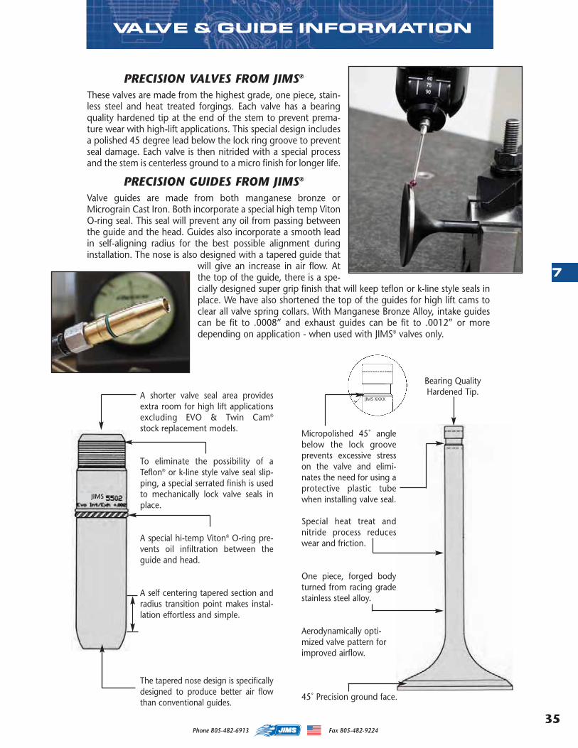
35
7
Phone 805-482-6913 Fax 805-482-9224
PRECISION VALVES FROM JIMS®
These valves are made from the highest grade, one piece, stain-less steel and heat treated forgings. Each valve has a bearingquality hardened tip at the end of the stem to prevent prema-ture wear with high-lift applications. This special design includesa polished 45 degree lead below the lock ring groove to preventseal damage. Each valve is then nitrided with a special processand the stem is centerless ground to a micro finish for longer life.
PRECISION GUIDES FROM JIMS®
Valve guides are made from both manganese bronze orMicrograin Cast Iron. Both incorporate a special high temp VitonO-ring seal. This seal will prevent any oil from passing betweenthe guide and the head. Guides also incorporate a smooth leadin self-aligning radius for the best possible alignment duringinstallation. The nose is also designed with a tapered guide that
will give an increase in air flow. Atthe top of the guide, there is a spe-cially designed super grip finish that will keep teflon or k-line style seals inplace. We have also shortened the top of the guides for high lift cams toclear all valve spring collars. With Manganese Bronze Alloy, intake guidescan be fit to .0008” and exhaust guides can be fit to .0012” or moredepending on application - when used with JIMS® valves only.
VALVE & GUIDE INFORMATION
Micropolished 45˚ anglebelow the lock grooveprevents excessive stresson the valve and elimi-nates the need for using aprotective plastic tubewhen installing valve seal.
Special heat treat andnitride process reduceswear and friction.
One piece, forged bodyturned from racing gradestainless steel alloy.
Aerodynamically opti-mized valve pattern forimproved airflow.
45˚ Precision ground face.
A shorter valve seal area providesextra room for high lift applicationsexcluding EVO & Twin Cam®
stock replacement models.
To eliminate the possibility of aTeflon® or k-line style valve seal slip-ping, a special serrated finish is usedto mechanically lock valve seals inplace.
A special hi-temp Viton® O-ring pre-vents oil infiltration between theguide and head.
A self centering tapered section andradius transition point makes instal-lation effortless and simple.
The tapered nose design is specificallydesigned to produce better air flowthan conventional guides.
Bearing QualityHardened Tip.
JIMS XXXX
JIMS XXXX
JIMS
MASTER 2013 CATALOG_JMS 2.qxp:Layout 1 8/2/12 8:26 PM Page 35

Phone 805-482-6913 Fax 805-482-922436
7
JIMS® completes the quest for the ultimate valve train system with the addition ofthese high-performance valves. Designed to withstand extreme racing conditions,these valves are constructed from a forged one piece racing grade stainlesssteel alloy, and specially heat-treated for superior wear resistance. Aspecial micropolished 45˚ angle just below the lock groove pre-vents excessive stress on the valve, and makes valve sealinstallation easier.
(Use on 1984-present EVO Big Twin, and 1999-04 Twin Cam® engines, and most aftermarket performance heads.)
PART NO. VALVE TYPE HEAD DIA. OVERALL LENGTH STEM DIA. PROFILENo.1314 Exhaust 1.480” 4.640” .3106” Dished HeadNo.1315 Intake 1.720” 4.560” .3108” Dished Head
EVO SPORTSTER® 883cc - 1200cc CONVERSION BLACK NITRIDE PRO VALVESThese valves are designed to convert 1986 to present EVO Sportsters 883cc - 1200cc dimensions.NOTE: Valve seats must be machined larger and deeper to accommodate the larger valves.
PART NO. VALVE TYPE HEAD DIA. OVERALL LENGTH STEM DIA. PROFILENo.1314S Exhaust 1.610” 4.565” .3106” Dished HeadNo.1315S Intake 2.020” 4.510” .3108” Dished Head
S&S ® REPLACEMENT BLACK NITRIDE PRO VALVES
No.1313
TWIN CAM/EVO BLACK NITRIDE PRO VALVES
JIMS® BLACK NITRIDE PERFORMANCE VALVES
PART NO. VALVE TYPE HEAD DIA. OVERALL LENGTH STEM DIA. PROFILENo.1310A Exhaust 1.610” 4.525” .3106” Dished HeadNo.1310B Exhaust 1.570” 4.525” .3106” Dished HeadNo.1311 Intake 1.900” 4.440” .3108” Dished HeadNo.1312 Intake 1.940” 4.440” .3108” Dished HeadNo.1313A Intake 2.020” 4.440” .3108” Dished HeadNo.1313 Intake 2.020” 4.490” .3108” Dished Head (+.050”)
No.1314S
RACEONLY
PERFORMANCE VALVES
MASTER 2013 CATALOG_JMS 2.qxp:Layout 1 8/2/12 8:26 PM Page 36
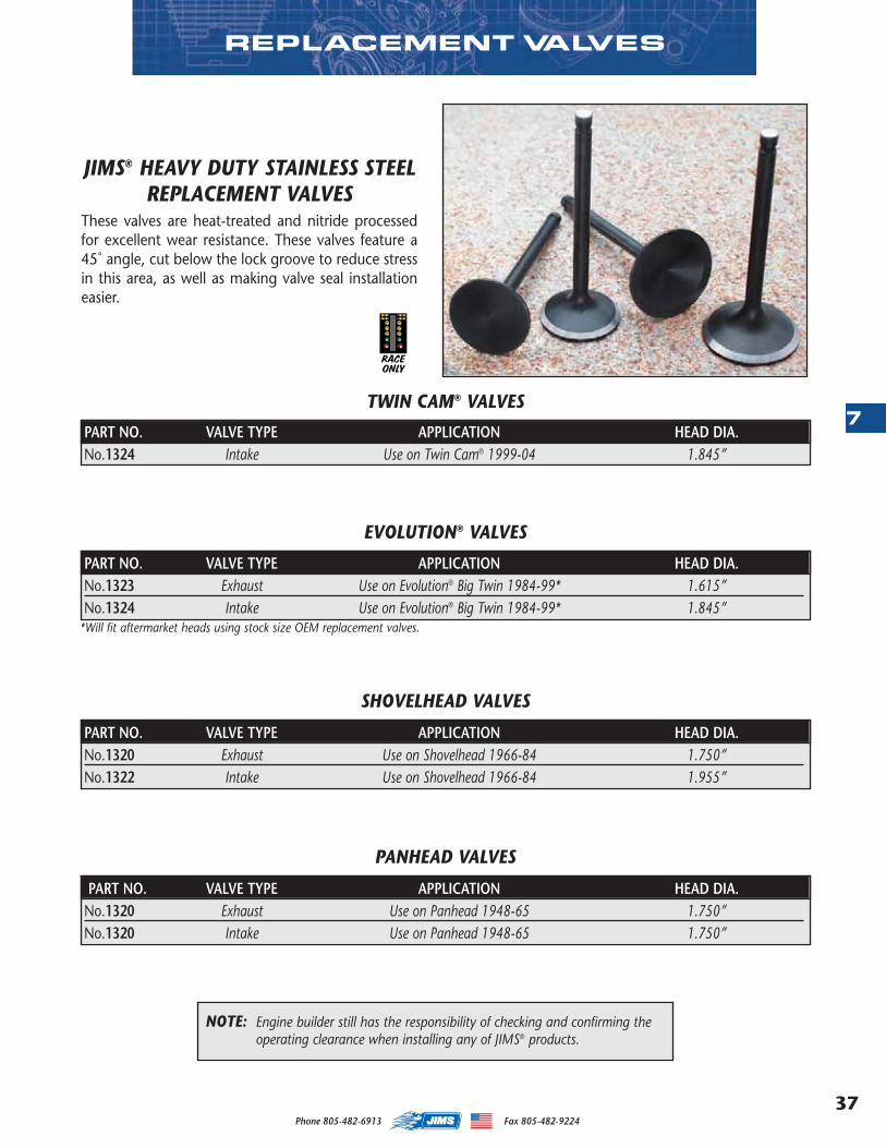
37
7
Phone 805-482-6913 Fax 805-482-9224
REPLACEMENT VALVES
JIMS® HEAVY DUTY STAINLESS STEELREPLACEMENT VALVES
These valves are heat-treated and nitride processedfor excellent wear resistance. These valves feature a45˚ angle, cut below the lock groove to reduce stressin this area, as well as making valve seal installationeasier.
PART NO. VALVE TYPE APPLICATION HEAD DIA.No.1320 Exhaust Use on Panhead 1948-65 1.750”No.1320 Intake Use on Panhead 1948-65 1.750”
PANHEAD VALVES
PART NO. VALVE TYPE APPLICATION HEAD DIA.No.1320 Exhaust Use on Shovelhead 1966-84 1.750”No.1322 Intake Use on Shovelhead 1966-84 1.955”
SHOVELHEAD VALVES
PART NO. VALVE TYPE APPLICATION HEAD DIA.No.1323 Exhaust Use on Evolution® Big Twin 1984-99* 1.615”No.1324 Intake Use on Evolution® Big Twin 1984-99* 1.845”
EVOLUTION® VALVES
PART NO. VALVE TYPE APPLICATION HEAD DIA.No.1324 Intake Use on Twin Cam® 1999-04 1.845”
TWIN CAM® VALVES
NOTE: Engine builder still has the responsibility of checking and confirming the operating clearance when installing any of JIMS® products.
*Will fit aftermarket heads using stock size OEM replacement valves.
RACEONLY
MASTER 2013 CATALOG_JMS 2.qxp:Layout 1 8/2/12 8:26 PM Page 37
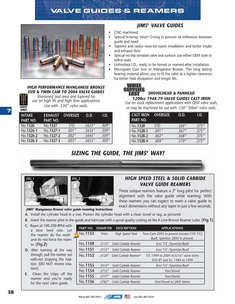
Phone 805-482-6913 Fax 805-482-922438
7
SHOVELHEAD & PANHEAD 1200cc 1948-79 VALVE GUIDES CAST IRON
Use on stock replacement applications with OEM valve seals,or may be machined for use with .530” Teflon® valve seals.
JIMS® VALVE GUIDES• CNC machined.• Special hi-temp, Viton® O-ring to prevent oil infiltration between
guide and head.• Tapered and radius nose for easier installation and better intake
and exhaust flow.• Special no-slip serrated valve seal surface: use either OEM style or
teflon seals.• Unfinished I.D., ready to be h oned or reamed after installation.• Micrograin Cast Iron or Manganese Bronze. This long lasting
bearing material allows you to fit the valve at a tighter clearancefor better heat dissipation and longer life.
HIGH-PERFORMANCE MANGANESE BRONZE EVO & TWIN CAM TO 2004 VALVE GUIDES
Shortened seal area and tapered foruse on high lift and high flow applications
Use with .530” valve seals.
INTAKE EXHAUST OVERSIZE O.D. I.D.PART NO. PART NO.No.1326 No.1327 STD .5625” .309”No.1326-1 No.1327-1 .001” .5635” .309”No.1326-2 No.1327-2 .002” .5645” .309”No.1326-3 No.1327-3 .003” .5655” .309”
CAST IRON OVERSIZE O.D. I.D.PART NO.No.1328 STD .566” .375”No.1328-1 .001” .567” .375”No.1328-2 .002” .568” .375”No.1328-4 .004” .570” .375”
JIMS® Manganese-Bronze valve guide reaming instructionsA. Install the cylinder head in a vise. Protect the cylinder head with a clean towel or rag, as pictured. B. Insert the reamer pilot in the guide and lubricate with a good quality cutting oil like K-Line Bronze Reamer Lube. (Fig.1)C. Ream at 100-200 RPM with
a slow feed rate. Letthe reamer do the workand do not force the ream-er. (Fig.2)
D. After reaming all the waythrough, pull the reamer outwith-out stopping the rota-tion. (DO NOT reverse rota-tion!)
E. Clean the chips off thereamer and you’re readyfor the next valve guide.
HIGH SPEED STEEL & SOLID CARBIDEVALVE GUIDE REAMERS
These unique reamers feature a 2" long pilot for perfectalignment with the valve guide while reaming. Withthese reamers you can expect to ream a valve guide toexact dimensions without any taper in just a few seconds.
PART NO. DIAMETER DESCRIPTION APPLICATIONS
No.1133 7mm High Speed Steel Twin Cam 2005 to present (except CVO T/C)Buell, Sportster 2004 to present.
No.1150 .3110” Solid Carbide Reamer Evo/ T/C /Sportster/Buell
No.1151 .3115” Solid Carbide Reamer Evo/ T/C /Sportster/Buell
No.1152 .3120” Solid Carbide Reamer* T/C 1999 to 2004 w/5/16” valve stemsEVO BT and XL, 1984 to 1999
No.1153 .3410” Solid Carbide Reamer Evo/ T/C /Sportster/Buell
No.1154 .3772” Solid Carbide Reamer Pan/Shovel
No.1155 .3777” Solid Carbide Reamer Pan/Shovel
No.1156 .3782” Solid Carbide Reamer Pan/Shovel w/ JIMS Valves
FIG.1 FIG.2
SIZING THE GUIDE, THE JIMS® WAY!
VALVE GUIDES & REAMERS
RACEONLY
NEW
MASTER 2013 CATALOG_JMS 2.qxp:Layout 1 8/2/12 8:26 PM Page 38
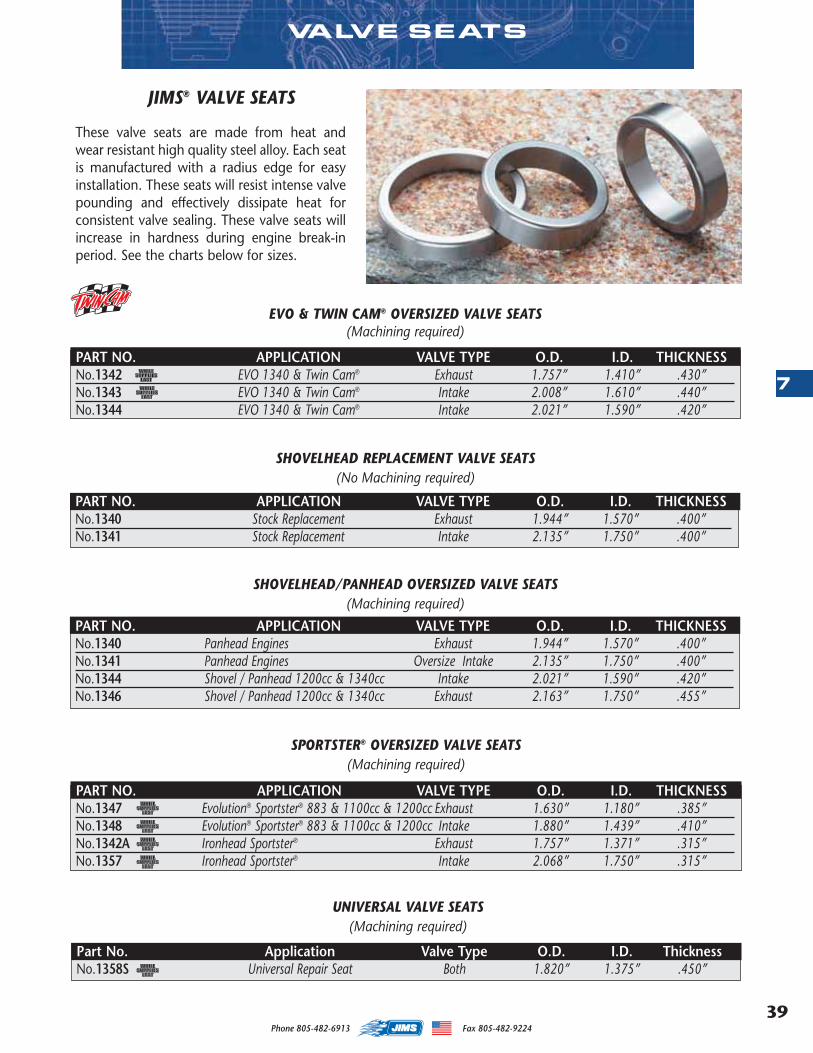
39
7
Phone 805-482-6913 Fax 805-482-9224
JIMS® VALVE SEATS
These valve seats are made from heat andwear resistant high quality steel alloy. Each seatis manufactured with a radius edge for easyinstallation. These seats will resist intense valvepounding and effectively dissipate heat forconsistent valve sealing. These valve seats willincrease in hardness during engine break-inperiod. See the charts below for sizes.
VALVE SEATS
PART NO. APPLICATION VALVE TYPE O.D. I.D. THICKNESSNo.1342 EVO 1340 & Twin Cam® Exhaust 1.757” 1.410” .430”No.1343 EVO 1340 & Twin Cam® Intake 2.008” 1.610” .440”No.1344 EVO 1340 & Twin Cam® Intake 2.021” 1.590” .420”
EVO & TWIN CAM® OVERSIZED VALVE SEATS(Machining required)
PART NO. APPLICATION VALVE TYPE O.D. I.D. THICKNESSNo.1340 Panhead Engines Exhaust 1.944” 1.570” .400”No.1341 Panhead Engines Oversize Intake 2.135” 1.750” .400”No.1344 Shovel / Panhead 1200cc & 1340cc Intake 2.021” 1.590” .420”No.1346 Shovel / Panhead 1200cc & 1340cc Exhaust 2.163” 1.750” .455”
SHOVELHEAD/PANHEAD OVERSIZED VALVE SEATS(Machining required)
PART NO. APPLICATION VALVE TYPE O.D. I.D. THICKNESSNo.1340 Stock Replacement Exhaust 1.944” 1.570” .400”No.1341 Stock Replacement Intake 2.135” 1.750” .400”
SHOVELHEAD REPLACEMENT VALVE SEATS(No Machining required)
Part No. Application Valve Type O.D. I.D. ThicknessNo.1358S Universal Repair Seat Both 1.820” 1.375” .450”
PART NO. APPLICATION VALVE TYPE O.D. I.D. THICKNESSNo.1347 Evolution® Sportster® 883 & 1100cc & 1200cc Exhaust 1.630” 1.180” .385”No.1348 Evolution® Sportster® 883 & 1100cc & 1200cc Intake 1.880” 1.439” .410”No.1342A Ironhead Sportster® Exhaust 1.757” 1.371” .315”No.1357 Ironhead Sportster® Intake 2.068” 1.750” .315”
SPORTSTER® OVERSIZED VALVE SEATS(Machining required)
UNIVERSAL VALVE SEATS(Machining required)
MASTER 2013 CATALOG_JMS 2.qxp:Layout 1 8/2/12 8:26 PM Page 39
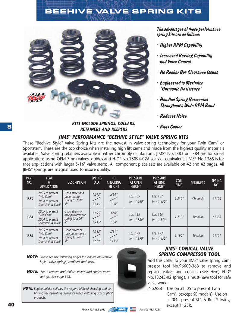
Phone 805-482-6913 Fax 805-482-922440
8
NOTE: Use to remove and replace valves and conical valvesprings. See page 145.
BEEHIVE VALVE SPRING KITS
JIMS® PERFORMANCE "BEEHIVE STYLE" VALVE SPRING KITSThese "Beehive Style" Valve Spring Kits are the newest in valve spring technology for your Twin Cam® orSportster®. These are the top choice when installing high lift cams and made from the highest quality materialsavailable. Valve spring retainers available in either chromoly or titanium. JIMS® No.1383 or 1384 are for streetapplications using OEM 7mm valves, guides and H-D® No.18094-02A seals or equivalent. JIMS® No.1385 is forrace applications with larger 5/16" valve stems. All component piece sets are available on 42 and 43 pages. AllJIMS® springs are magnafluxed to insure quality.
KITS INCLUDE SPRINGS, COLLARS, RETAINERS AND KEEPERS
The advantages of these performancespring kits are as follows:
• Higher RPM Capability
• Increased Revving Capabilityand Valve Control
• No Rocker Box Clearance Issues
• Engineered to Maximize"Harmonic Resistance"
• Handles Spring HarmonicsThroughout a Wide RPM Band
• Reduces Noise
• Runs Cooler
1383
NOTE: Engine builder still has the responsibility of checking and con-firming the operating clearance when installing any of JIMS®
products.
2005 to presentTwin Cam®
2004 to presentSportster® & Buell®
Good street andperformancespring to .600”lift
Lbs. 155In. - 1.880”
Lbs. 167In. - 1.850”
1.230” Chromoly #13001.095”
1.445”
.650”
1.00”
1384
2005 to presentTwin Cam®
2004 to presentSportster® & Buell®
Good street orrace performancespring to .600”lift
Lbs. 155In. - 1.880”
Lbs. 166In. - 1.850”
1.230” Titanium #13001.095”
1.445”
.650”
1.00”
PRESSUREAT BINDHEIGHT
COILBIND
SPRINGNO.
PRESSUREAT OPENHEIGHT
I.D.CHECKING
HEIGHT
SPRINGO.D.DESCRIPTION RETAINERS
YEAR&
APPLICATION
PARTNO.
1385
2005 to presentTwin Cam®
2004 to presentSportster® & Buell®
Good street orrace performancespring to .690”lift
Lbs. 179In. - 1.190”
Lbs. 193In. - 1.850”
1.190” Titanium #13011.185”
1.589”
.731”
1.135”
NOTE: Please see the following pages for individual“Beehive Style” valve springs, retainers and locks. Add this collar to your JIMS® valve spring com-
pressor tool No.96600-36B to remove andreplace valves and conical (Bee Hive) H-D®
No.18245-02 springs, a must-have tool for safevalve work.No.988 - Use on all ‘05 to present Twin
Cam®, (except SE models). Use onall ‘04 - present XL’s & Buell® Twins,except 1125R.
JIMS® CONICAL VALVESPRING COMPRESSOR TOOL
MASTER 2013 CATALOG_JMS 2.qxp:Layout 1 8/2/12 8:26 PM Page 40
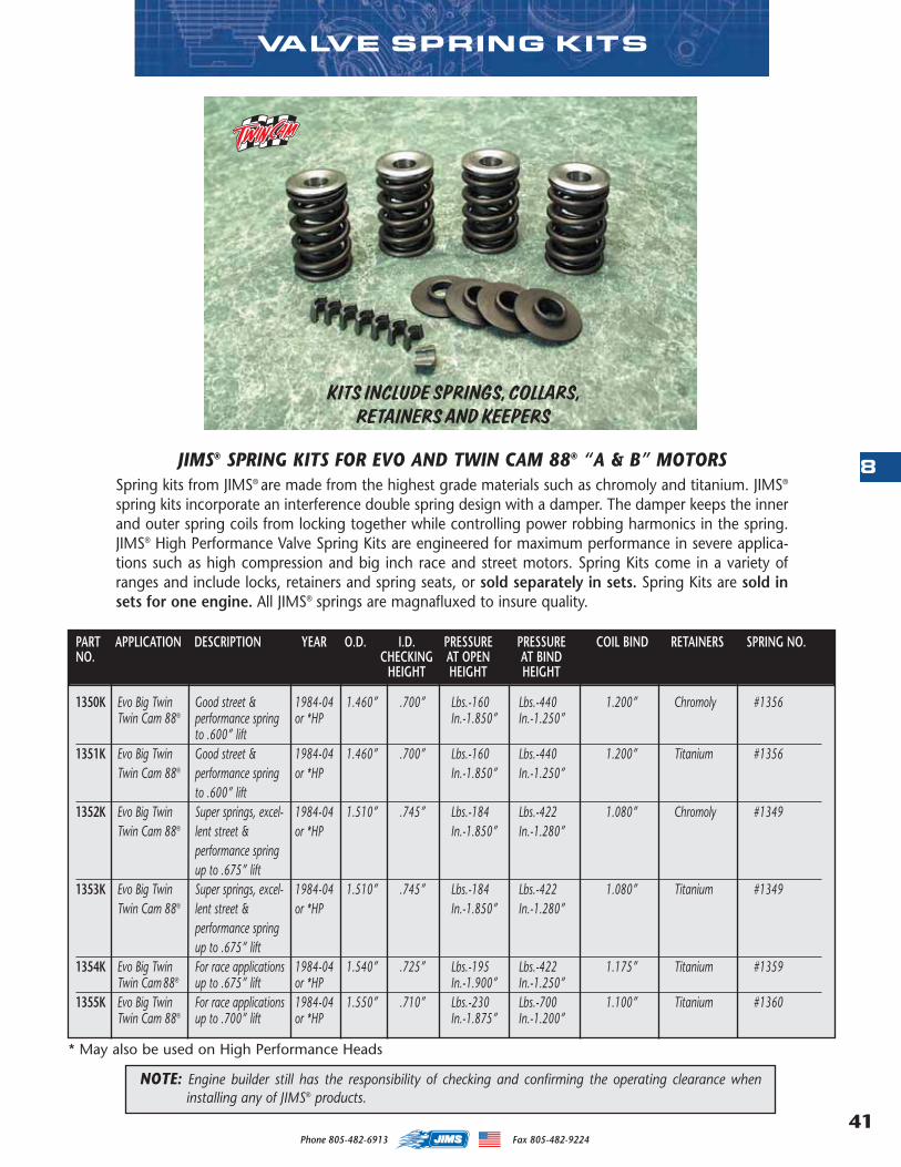
41
8
Phone 805-482-6913 Fax 805-482-9224
VALVE SPRING KITS
1350K Evo Big Twin Good street & 1984-04 1.460” .700” Lbs.-160 Lbs.-440 1.200” Chromoly #1356Twin Cam 88® performance spring or *HP In.-1.850” In.-1.250”
to .600” lift1351K Evo Big Twin Good street & 1984-04 1.460” .700” Lbs.-160 Lbs.-440 1.200” Titanium #1356
Twin Cam 88® performance spring or *HP In.-1.850” In.-1.250”to .600” lift
1352K Evo Big Twin Super springs, excel- 1984-04 1.510” .745” Lbs.-184 Lbs.-422 1.080” Chromoly #1349Twin Cam 88® lent street & or *HP In.-1.850” In.-1.280”
performance springup to .675” lift
1353K Evo Big Twin Super springs, excel- 1984-04 1.510” .745” Lbs.-184 Lbs.-422 1.080” Titanium #1349Twin Cam 88® lent street & or *HP In.-1.850” In.-1.280”
performance springup to .675” lift
1354K Evo Big Twin For race applications 1984-04 1.540” .725” Lbs.-195 Lbs.-422 1.175” Titanium #1359Twin Cam 88® up to .675” lift or *HP In.-1.900” In.-1.250”
1355K Evo Big Twin For race applications 1984-04 1.550” .710” Lbs.-230 Lbs.-700 1.100” Titanium #1360Twin Cam 88® up to .700” lift or *HP In.-1.875” In.-1.200”
PART APPLICATION DESCRIPTION YEAR O.D. I.D. PRESSURE PRESSURE COIL BIND RETAINERS SPRING NO.NO. CHECKING AT OPEN AT BIND
HEIGHT HEIGHT HEIGHT
JIMS® SPRING KITS FOR EVO AND TWIN CAM 88® “A & B” MOTORSSpring kits from JIMS® are made from the highest grade materials such as chromoly and titanium. JIMS®
spring kits incorporate an interference double spring design with a damper. The damper keeps the innerand outer spring coils from locking together while controlling power robbing harmonics in the spring.JIMS® High Performance Valve Spring Kits are engineered for maximum performance in severe applica-tions such as high compression and big inch race and street motors. Spring Kits come in a variety ofranges and include locks, retainers and spring seats, or sold separately in sets. Spring Kits are sold insets for one engine. All JIMS® springs are magnafluxed to insure quality.
KITS INCLUDE SPRINGS, COLLARS, RETAINERS AND KEEPERS
NOTE: Engine builder still has the responsibility of checking and confirming the operating clearance wheninstalling any of JIMS® products.
* May also be used on High Performance Heads
MASTER 2013 CATALOG_JMS 2.qxp:Layout 1 8/2/12 8:26 PM Page 41
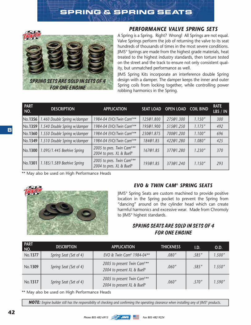
Phone 805-482-6913 Fax 805-482-922442
8
SPRING & SPRING SEATS
PERFORMANCE VALVE SPRING SETSA Spring is a Spring. Right? Wrong! All Springs are not equal.Valve Springs perform the job of returning the valve to its seathundreds of thousands of times in the most severe conditions.JIMS® Springs are made from the highest grade materials, heattreated to the highest industry standards, then torture testedon the street and the track to ensure not only consistent qual-ity, but unmatched performance as well. JIMS Spring Kits incorporate an interference double Springdesign with a damper. The damper keeps the inner and outerSpring coils from locking together, while controlling powerrobbing harmonics in the Spring.
SPRING SETS ARE SOLD IN SETS OF 4 FOR ONE ENGINE
SPRING SEATS ARE SOLD IN SETS OF 4 FOR ONE ENGINE
EVO & TWIN CAM® SPRING SEATSJIMS® Spring Seats are custom machined to provide positivelocation in the Spring pocket to prevent the Spring from“dancing” around on the cylinder head which can createharmful harmonics and excessive wear. Made from Chromolyto JIMS® highest standards.
PART # DESCRIPTION I.D.SEAT LOA OPEN LOAD COIL BIND RATE
No.1356 1.460 Double Spring w/damper 1984-04 EVO/Twin Cam® ** [email protected] [email protected] 1.150” 300
No.1359 1.540 Double Spring w/damper 1984-04 EVO/Twin Cam®** [email protected] [email protected] 1.175” 492
No.1360 1.550 Double Spring w/damper 1984-04 EVO/Twin Cam®** [email protected] [email protected] 1.100” 696
No.1349 1.510 Double Spring w/damper 1984-04 EVO/Twin Cam®** [email protected] [email protected] 1.080” 425
No.1300 1.095/1.445 Beehive Spring 2005 to pres. Twin Cam®** [email protected] [email protected] 1.230” 3702004 to pres. XL & Buell®
No.1301 1.185/1.589 Beehive Spring 2005 to pres. Twin Cam®**2004 to pres. XL & Buell® [email protected] [email protected] 1.150” 293
DESCRIPTION APPLICATION SEAT LOAD OPEN LOAD COIL BINDRATELBS / IN
NOTE: Engine builder still has the responsibility of checking and confirming the operating clearance when installing any of JIMS® products.
No.1377 Spring Seat (Set of 4)
2005 to present Twin Cam®**2004 to present XL & Buell®
EVO & Twin Cam® 1984-04**
THICKNESSDESCRIPTION APPLICATION I.D. O.D.
.080” .585” 1.500”
No.1309 Spring Seat (Set of 4) .060” .585” 1.550”
2005 to present Twin Cam® **2004 to present XL & Buell®
No.1317 Spring Seat (Set of 4) .060” .570” 1.590”
PARTNO.
PARTNO.
** May also be used on High Performance Heads
** May also be used on High Performance Heads
MASTER 2013 CATALOG_JMS 2.qxp:Layout 1 8/2/12 8:26 PM Page 42
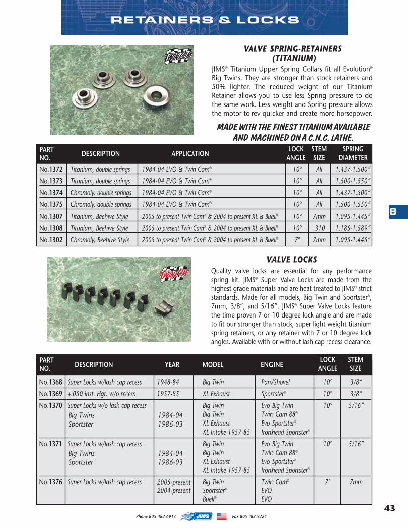
43
8
Phone 805-482-6913 Fax 805-482-9224
No.1372 Titanium, double springs 1984-04 EVO & Twin Cam® 10° All 1.437-1.500”
No.1373 Titanium, double springs 1984-04 EVO & Twin Cam® 10° All 1.500-1.550”
No.1374 Chromoly, double springs 1984-04 EVO & Twin Cam® 10° All 1.437-1.500”
No.1375 Chromoly, double springs 1984-04 EVO & Twin Cam® 10° All 1.500-1.550”
No.1307 Titanium, Beehive Style 2005 to present Twin Cam® & 2004 to present XL & Buell® 10° 7mm 1.095-1.445”
No.1308 Titanium, Beehive Style 2005 to present Twin Cam® & 2004 to present XL & Buell® 10° .310 1.185-1.589”
No.1302 Chromoly, Beehive Style 2005 to present Twin Cam® & 2004 to present XL & Buell® 7° 7mm 1.095-1.445”
RETAINERS & LOCKS
VALVE SPRING-RETAINERS(TITANIUM)
JIMS® Titanium Upper Spring Collars fit all Evolution®
Big Twins. They are stronger than stock retainers and50% lighter. The reduced weight of our TitaniumRetainer allows you to use less Spring pressure to dothe same work. Less weight and Spring pressure allowsthe motor to rev quicker and create more horsepower.
VALVE LOCKSQuality valve locks are essential for any performancespring kit. JIMS® Super Valve Locks are made from thehighest grade materials and are heat treated to JIMS® strictstandards. Made for all models, Big Twin and Sportster®,7mm, 3/8”, and 5/16”. JIMS® Super Valve Locks featurethe time proven 7 or 10 degree lock angle and are madeto fit our stronger than stock, super light weight titaniumspring retainers, or any retainer with 7 or 10 degree lockangles. Available with or without lash cap recess clearance.
DESCRIPTION APPLICATIONLOCK STEM SPRING
ANGLE SIZE DIAMETER
PART # DESCRIPTION YEAR MODE ENNE LOCK ANGLE VALVE STEM SIZE
No.1368 Super Locks w/lash cap recess 1948-84 Big Twin Pan/Shovel 10° 3/8”
No.1369 +.050 inst. Hgt. w/o recess 1957-85 XL Exhaust Sportster® 10° 3/8”
No.1370 Super Locks w/o lash cap recess Big Twin Evo Big Twin 10° 5/16”Big Twin Twin Cam 88®
XL Exhaust Evo Sportster®
XL Intake 1957-85 Ironhead Sportster®
No.1371 Super Locks w/lash cap recess Big Twin Evo Big Twin 10° 5/16”Big Twin Twin Cam 88®
XL Exhaust Evo Sportster®
XL Intake 1957-85 Ironhead Sportster®
No.1376 Super Locks w/lash cap recess Big Twin Twin Cam® 7° 7mmSportster® EVOBuell® EVO
DESCRIPTION YEAR MODEL ENGINELOCK STEM
ANGLE SIZE
Big Twins 1984-04Sportster 1986-03
Big Twins 1984-04Sportster 1986-03
2005-present2004-present
PARTNO.
PARTNO.
MADE WITH THE FINEST TITANIUM AVAILABLEAND MACHINED ON A C.N.C. LATHE.
MASTER 2013 CATALOG_JMS 2.qxp:Layout 1 8/2/12 8:26 PM Page 43

Phone 805-482-6913 Fax 805-482-922444
8
PUSHROD COVERS & .ACCESSORIES
NEW
PUSHROD COVER SPACERSJIMS® spacers are used to space up the pushrod cov-ers above when taller than stock cylinders are used.Available in four sizes.
No.1093SP4K - .275 Thick - Pack of 4.
No.1093SP3K - .225 Thick - Pack of 4.
No.1093SP2K - .200 Thick - Pack of 4.
No.1093SP1K - .155 Thick - Pack of 4.
Use these for Taller Motors
BILLET TWIN CAM OR EVOPUSHROD COVER SET
These "A Cut Above" billet pushrod cov-ers are styled to give you a clean andsmooth look. They feature a unique clipthat looks like a complete tube while retaining the simple push-pull spring type function. Will work on anylength cylinders utilizing spacer kits that are available below. NOTE: Will not fit JIMS stroker kit cylinders. For moredetails see No.3001-IS instructions.TWIN CAMNo.3000 - Bright dipped anodized.No.3003 - Black anodized.No.3004 - Chrome.No.3005 - Polished.
PUSHROD COVER CLIP INSTALLINGAND REMOVER TOOL
First thought…why would I need this tool, when I’ve beeninstalling and removing OEM style pushrod cov-ers for years with just a screw driver? Made fromblack delrin, this tool will NOT marr or slip – andwill install the clip professionally with just onehand in seconds! It’s a luxury tool you willappreciate for years to come. For more details seeNo.917-IS instructions.No. 917 - Use on all V-Twins that use pushrod clips.
NEW
NEW
NEW WELDED
COVERS
SEE PAGE 68
EVOLUTIONNo.3002 - Chrome.No.3001 - Polished.
Black
Garry Hughes
MASTER 2013 CATALOG_JMS 2.qxp:Layout 1 8/2/12 8:26 PM Page 44
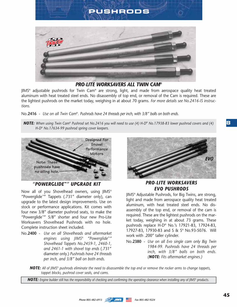
45
8
Phone 805-482-6913 Fax 805-482-9224
PUSHRODS
NOTE: Engine builder still has the responsibility of checking and confirming the operating clearance when installing any of JIMS® products.
EVO
NOTE: All of JIMS® pushrods eliminate the need to disassemble the top end or remove the rocker arms to change tappets,tappet blocks, pushrod cover seals, and cams.
PRO-LITE WORKSAVERS EVO PUSHRODS
JIMS® Adjustable Pushrods, for Big Twins, are strong,light and made from aerospace quality heat treatedaluminum, with heat treated steel ends. No dis-assembly of the top end, or removal of the cam isrequired. These are the lightest pushrods on the mar-ket today, weighing in at about 73 grams. Thesepushrods replace H-D® No.’s 17921-83, 17924-83,17927-83, 17930-83 and S & S® No.93-5076. Willwork with .200” taller cylinder.No.2380 - Use on all Evo single cam only Big Twin
1984-99. Pushrods have 24 threads perinch, with 3/8” balls on both ends.(NOTE: Fits aftermarket engines.)
“POWERGLIDE™” UPGRADE KITNow all of you Shovelhead owners, using JIMS®
“Powerglide™” Tappets (.731” diameter only), canupgrade to the latest design improvements. Use onstock or performance applications. Kit comes withfour new 3/8” diameter pushrod seats, to make the“Powerglide™” 5/8” shorter and four new Pro-LiteWorksavers Shovelhead Pushrods with no hole.Complete instruction sheet included. No.2400 - Use on all Shovelheads and aftermarket
engines using JIMS® “Powerglide™”Shovelhead Tappets No.2459-1, 2460-1,and 2461-1 with shovel top ends (.731”diameter only.) Pushrods have 24 threadsper inch, and 3/8” ball on both ends.
Note: Thesepushrods haveno oiling hole.
Designed ForShovel
PerformanceMotors
PRO-LITE WORKSAVERS ALL TWIN CAM®
JIMS® adjustable pushrods for Twin Cam® are strong, light, and made from aerospace quality heat treatedaluminum with heat treated steel ends. No disassembly of top end, or removal of the Cam is required. These arethe lightest pushrods on the market today, weighing in at about 70 grams. For more details see No.2416-IS instruc-tions.
No.2416 - Use on all Twin Cam®. Pushrods have 24 threads per inch, with 3/8” balls on both ends.
NOTE: When using Twin Cam® Pushrod set No.2416 you will need to use (4) H-D® No.17938-83 lower pushrod covers and (4)H-D® No.17634-99 pushrod spring cover keepers.
MASTER 2013 CATALOG_JMS 2.qxp:Layout 1 8/2/12 8:26 PM Page 45
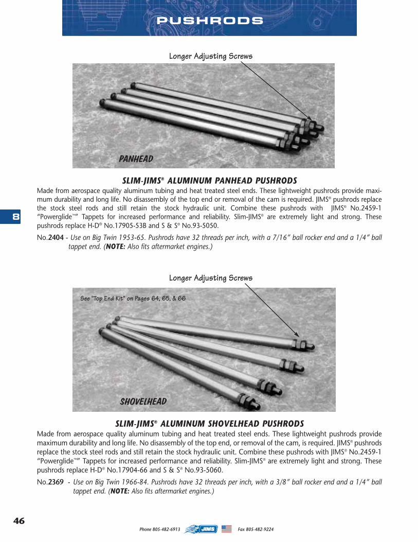
Phone 805-482-6913 Fax 805-482-922446
8
PANHEAD
SHOVELHEAD
SLIM-JIMS® ALUMINUM PANHEAD PUSHRODSMade from aerospace quality aluminum tubing and heat treated steel ends. These lightweight pushrods provide maxi-mum durability and long life. No disassembly of the top end or removal of the cam is required. JIMS® pushrods replacethe stock steel rods and still retain the stock hydraulic unit. Combine these pushrods with JIMS® No.2459-1“Powerglide™” Tappets for increased performance and reliability. Slim-JIMS® are extremely light and strong. Thesepushrods replace H-D® No.17905-53B and S & S® No.93-5050.
No.2404 - Use on Big Twin 1953-65. Pushrods have 32 threads per inch, with a 7/16” ball rocker end and a 1/4” balltappet end. (NOTE: Also fits aftermarket engines.)
SLIM-JIMS® ALUMINUM SHOVELHEAD PUSHRODSMade from aerospace quality aluminum tubing and heat treated steel ends. These lightweight pushrods providemaximum durability and long life. No disassembly of the top end, or removal of the cam, is required. JIMS® pushrodsreplace the stock steel rods and still retain the stock hydraulic unit. Combine these pushrods with JIMS® No.2459-1“Powerglide™” Tappets for increased performance and reliability. Slim-JIMS® are extremely light and strong. Thesepushrods replace H-D® No.17904-66 and S & S® No.93-5060.
No.2369 - Use on Big Twin 1966-84. Pushrods have 32 threads per inch, with a 3/8” ball rocker end and a 1/4” balltappet end. (NOTE: Also fits aftermarket engines.)
Longer Adjusting Screws
See "Top End Kit" on Pages 64, 65, & 66
Longer Adjusting Screws
PUSHRODS
MASTER 2013 CATALOG_JMS 2.qxp:Layout 1 8/2/12 8:26 PM Page 46
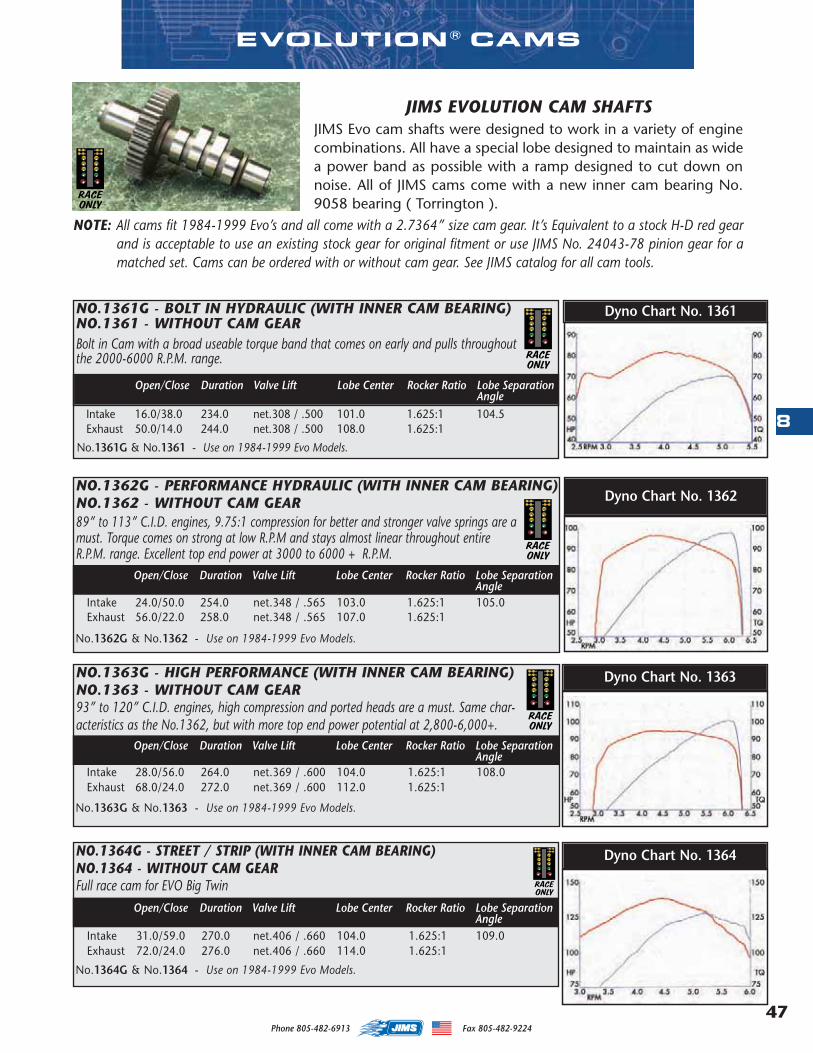
47
8
Phone 805-482-6913 Fax 805-482-9224
JIMS EVOLUTION CAM SHAFTSJIMS Evo cam shafts were designed to work in a variety of enginecombinations. All have a special lobe designed to maintain as widea power band as possible with a ramp designed to cut down onnoise. All of JIMS cams come with a new inner cam bearing No.9058 bearing ( Torrington ).
NOTE: All cams fit 1984-1999 Evo’s and all come with a 2.7364” size cam gear. It’s Equivalent to a stock H-D red gearand is acceptable to use an existing stock gear for original fitment or use JIMS No. 24043-78 pinion gear for amatched set. Cams can be ordered with or without cam gear. See JIMS catalog for all cam tools.
RACEONLY
NO.1361G - BOLT IN HYDRAULIC (WITH INNER CAM BEARING)NO.1361 - WITHOUT CAM GEARBolt in Cam with a broad useable torque band that comes on early and pulls throughoutthe 2000-6000 R.P.M. range.
Intake 16.0/38.0 234.0 net.308 / .500 101.0 1.625:1 104.5Exhaust 50.0/14.0 244.0 net.308 / .500 108.0 1.625:1
No.1361G & No.1361 - Use on 1984-1999 Evo Models.
RACEONLY
EVOLUTION ® CAMS
NO.1362G - PERFORMANCE HYDRAULIC (WITH INNER CAM BEARING)NO.1362 - WITHOUT CAM GEAR89” to 113” C.I.D. engines, 9.75:1 compression for better and stronger valve springs are amust. Torque comes on strong at low R.P.M and stays almost linear throughout entireR.P.M. range. Excellent top end power at 3000 to 6000 + R.P.M.
Intake 24.0/50.0 254.0 net.348 / .565 103.0 1.625:1 105.0Exhaust 56.0/22.0 258.0 net.348 / .565 107.0 1.625:1
No.1362G & No.1362 - Use on 1984-1999 Evo Models.
Open/Close Duration Valve Lift Lobe Center Rocker Ratio Lobe SeparationAngle
NO.1363G - HIGH PERFORMANCE (WITH INNER CAM BEARING)NO.1363 - WITHOUT CAM GEAR93” to 120” C.I.D. engines, high compression and ported heads are a must. Same char-acteristics as the No.1362, but with more top end power potential at 2,800-6,000+.
Intake 28.0/56.0 264.0 net.369 / .600 104.0 1.625:1 108.0Exhaust 68.0/24.0 272.0 net.369 / .600 112.0 1.625:1
No.1363G & No.1363 - Use on 1984-1999 Evo Models.
Open/Close Duration Valve Lift Lobe Center Rocker Ratio Lobe SeparationAngle
NO.1364G - STREET / STRIP (WITH INNER CAM BEARING)NO.1364 - WITHOUT CAM GEARFull race cam for EVO Big Twin
Intake 31.0/59.0 270.0 net.406 / .660 104.0 1.625:1 109.0Exhaust 72.0/24.0 276.0 net.406 / .660 114.0 1.625:1
No.1364G & No.1364 - Use on 1984-1999 Evo Models.
Open/Close Duration Valve Lift Lobe Center Rocker Ratio Lobe SeparationAngle
RACEONLY
Open/Close Duration Valve Lift Lobe Center Rocker Ratio Lobe SeparationAngle
Dyno Chart No. 1361
Dyno Chart No. 1362
Dyno Chart No. 1363
RACEONLY
Dyno Chart No. 1364
RACEONLY
MASTER 2013 CATALOG_JMS 2.qxp:Layout 1 8/2/12 8:26 PM Page 47
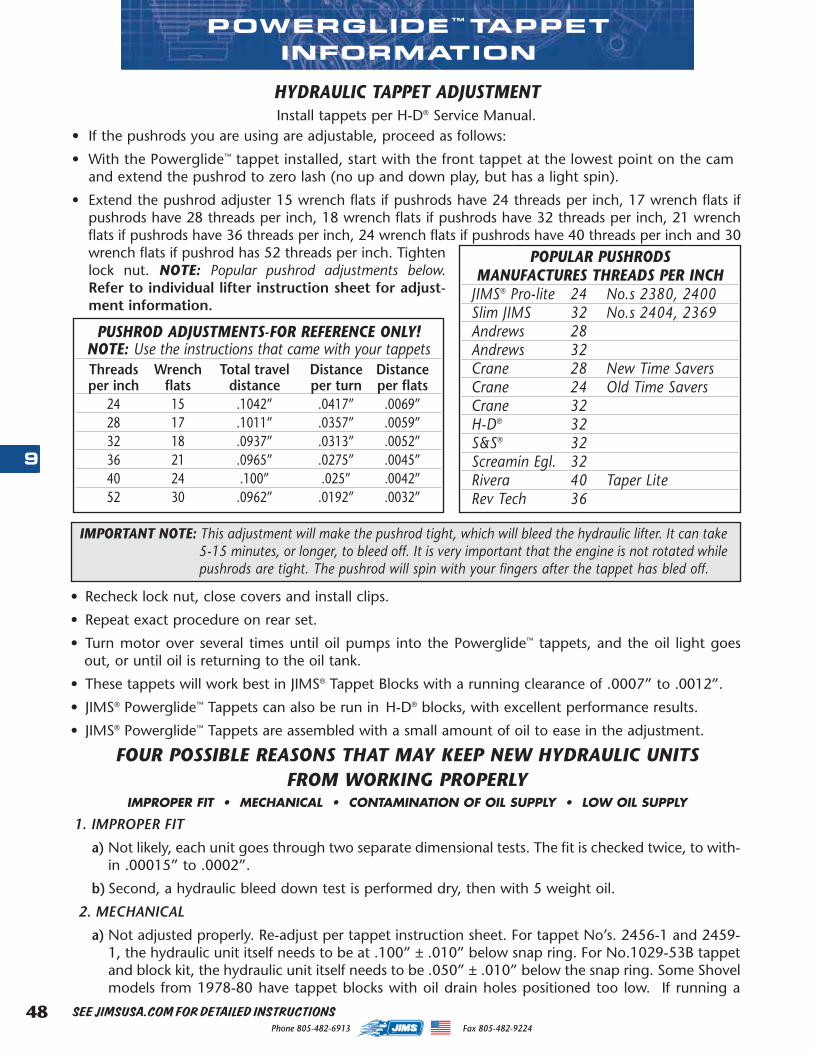
Phone 805-482-6913 Fax 805-482-922448
9
HYDRAULIC TAPPET ADJUSTMENT Install tappets per H-D® Service Manual.
• If the pushrods you are using are adjustable, proceed as follows:
• With the Powerglide™ tappet installed, start with the front tappet at the lowest point on the cam and extend the pushrod to zero lash (no up and down play, but has a light spin).
• Extend the pushrod adjuster 15 wrench flats if pushrods have 24 threads per inch, 17 wrench flats ifpushrods have 28 threads per inch, 18 wrench flats if pushrods have 32 threads per inch, 21 wrenchflats if pushrods have 36 threads per inch, 24 wrench flats if pushrods have 40 threads per inch and 30wrench flats if pushrod has 52 threads per inch. Tightenlock nut. NOTE: Popular pushrod adjustments below.Refer to individual lifter instruction sheet for adjust-ment information.
POWERGLIDE ™ TAPPET INFORMATION
IMPORTANT NOTE: This adjustment will make the pushrod tight, which will bleed the hydraulic lifter. It can take5-15 minutes, or longer, to bleed off. It is very important that the engine is not rotated whilepushrods are tight. The pushrod will spin with your fingers after the tappet has bled off.
FOUR POSSIBLE REASONS THAT MAY KEEP NEW HYDRAULIC UNITS FROM WORKING PROPERLY
IMPROPER FIT • MECHANICAL • CONTAMINATION OF OIL SUPPLY • LOW OIL SUPPLY
1. IMPROPER FIT
a) Not likely, each unit goes through two separate dimensional tests. The fit is checked twice, to with-in .00015” to .0002”.
b) Second, a hydraulic bleed down test is performed dry, then with 5 weight oil.
2. MECHANICAL
a) Not adjusted properly. Re-adjust per tappet instruction sheet. For tappet No’s. 2456-1 and 2459-1, the hydraulic unit itself needs to be at .100” ± .010” below snap ring. For No.1029-53B tappetand block kit, the hydraulic unit itself needs to be .050” ± .010” below the snap ring. Some Shovelmodels from 1978-80 have tappet blocks with oil drain holes positioned too low. If running a
SEE JIMSUSA.COM FOR DETAILED INSTRUCTIONS
• Recheck lock nut, close covers and install clips.
• Repeat exact procedure on rear set.
• Turn motor over several times until oil pumps into the Powerglide™ tappets, and the oil light goesout, or until oil is returning to the oil tank.
• These tappets will work best in JIMS® Tappet Blocks with a running clearance of .0007” to .0012”.
• JIMS® Powerglide™ Tappets can also be run in H-D® blocks, with excellent performance results.
• JIMS® Powerglide™ Tappets are assembled with a small amount of oil to ease in the adjustment.
PUSHROD ADJUSTMENTS-FOR REFERENCE ONLY!NOTE: Use the instructions that came with your tappetsThreads Wrench Total travel Distance Distanceper inch flats distance per turn per flats
24 15 .1042” .0417” .0069”28 17 .1011” .0357” .0059”32 18 .0937” .0313” .0052”36 21 .0965” .0275” .0045”40 24 .100” .025” .0042”52 30 .0962” .0192” .0032”
POPULAR PUSHRODSMANUFACTURES THREADS PER INCH
JIMS® Pro-lite 24 No.s 2380, 2400Slim JIMS 32 No.s 2404, 2369Andrews 28Andrews 32Crane 28 New Time SaversCrane 24 Old Time SaversCrane 32H-D® 32S&S® 32Screamin Egl. 32Rivera 40 Taper LiteRev Tech 36
MASTER 2013 CATALOG_JMS 2.qxp:Layout 1 8/2/12 8:26 PM Page 48
49
9
Phone 805-482-6913 Fax 805-482-9224
POWERGLIDE ™ TAPPET INFORMATION
THE FOLLOWING IS SOMETIMES MISTAKEN FOR NOISY TAPPETS:A. The most common being the clearance between cam gear and pinion gear (referred to as gear lash). If you did
not change the cam at the time of installing this kit and had no gear lash but a slight whine when motor was cold,it is safe to say you are OK in this area.
B. Rocker arm end play at .004” to .010” is good.
C. Oil pressure at normal operating temperature about 2000 RPM should be 12-35 p.s.i. on Big Twin models, and 10-17p.s.i. at 2500 RPM on Sportster® models.
D. Check valve to guide clearance.
E. Some Cams with fast ramps.
higher lift cam than stock, and sometimes even stock, these blocks will allow oil pressure to bleedoff from the tappets. This is most common in the front tappet block.
b) Any one of the following will cause a valve train to become noisy; a bent pushrod, loose valveguides, a broken valve spring, a valve hitting a piston, a valve hitting a valve, a loose rocker bush-ing, a rocker tip wearing at the valve stem, and a lifter roller hitting the tappet block will all causea noisy valve train.
c) Gear lash: If you did not change the cam at the time you installed new hydraulic units and had nogear lash, but a slight whine when motor was cold, it is safe to say you are OK in this area.
d) Broken hydraulic valve spring which is not allowing valve to seal. If this is the case the hydraulicunit will not hold oil pressure. We have not seen this situation on any of JIMS® hydraulic units.
To check this, hold pushrod with your hand (with lifter on the heel of cam valve shut) and pushdown on pushrod. Hydraulic unit will feel spongy. Do not mistake this for no oil getting to tappet.If all tappets are spongy, this indicates there is no oil. If just one tappet is spongy that has beenre-adjusted, but will not pump up, replace the tappet.
3. CONTAMINATION OF OIL
a) With contamination of oil, the hydraulic unit may work for a minute and then become noisy. Mostof the time it is more than one hydraulic unit that will be contaminated to the point of being stuckin the downward position.
b) Re-adjust per instruction sheet. If hydraulic unit will not come back up to the top of snap ring,replace hydraulic unit and wash out the entire oil system.
4. OIL PRESSURE AT NORMAL OPERATING TEMPERATURE, AT ABOUT 2000 RPM, SHOULD BE12-35p.s.i..
a) Check lifter filter screen (Big Twin).
b) Make sure you are getting oil to the lifters. Install oil pressure gauge for top end oil.
c) Lifter to tappet block clearance is best at .0007”-.0012”.
d) Lifters work best with 20-50w motorcycle oil.
e) If lifters are quiet when cold or at a low RPM range and become noisy as RPM is increased, thereis either not enough oil pressure, or too much clearance from lifter to block bore (Refer to “c”).
f) To isolate a possible noisy hydraulic lifter, start with a cool motor and the lifter you think is makingthe noise. With the lifter on the heel of cam, valve shut, adjust the pushrod so lifter unit is all theway compressed down. This is very important! This adjustment will make the pushrod tight whichwill bleed down the hydraulic lifter. It will sometimes take five minutes, or longer, to bleed down.Do not rotate engine while pushrods are tight. Go to the point where the pushrod will spin withyour fingers. Adjust down a little more until pushrod becomes tight (so you can just barely turnwith your fingers). Start bike. If it is quiet, then you have found the lifter that was not working prop-erly. If it is still noisy, continue with the next lifter until you have located the the noisy one. Readjustper instruction sheet, or replace lifter.
MASTER 2013 CATALOG_JMS 2.qxp:Layout 1 8/2/12 8:26 PM Page 49

Phone 805-482-6913 Fax 805-482-922450
9
NEW
TWIN CAM® CASE SAVER FOR OVERSIZE TAPPETS
This new tool can be a case saver if you have worn out or damaged tappet bores on any Twin Camengine case. This reamer tool is designed to ream the case to fit a JIMS No.1811 +.010 oversize TwinCam Powerglide™ II lifter. This tool includes a top quality reamer designed to perform a perfect finishhone on each tappet hole. For more details see No.789-IS instructions.
No.789- Use on any Twin Cam engine, OEM, or aftermarket.
TWIN CAM ®, POWERGLIDETOOLS
SEE JIMSUSA.COM FOR DETAILED INSTRUCTIONS
Optional EVOSleeve
JIMS TAPPET PUMP AND TEST STAND Having issues getting your tappets to pump up or not sure if youhave an oiling problem? Isolate the issue by using the new JIMStappet pump and test stand. Fits standard sizeTwin Cam or Evolution lifters. For moreinformation see part No. 765 and No. 766on page 131.
NEW
Bob Grimes Charly Abraham
MASTER 2013 CATALOG_JMS 2.qxp:Layout 1 8/2/12 8:26 PM Page 50
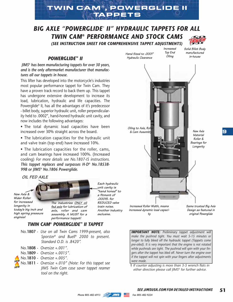
51
9
Phone 805-482-6913 Fax 805-482-9224
New Axle &Wider Rollerfor increasedlongevity intoday’s big inch andhigh spring pressureengines!
TWIN CAM ®, POWERGLIDE IITAPPETS
POWERGLIDE™ II JIMS® has been manufacturing tappets for over 30 years,
and is the only aftermarket manufacturer that manufac-tures all our tappets in house. This lifter has developed into the motorcycle's industriesmost popular performance tappet for Twin Cam. Theyhave a proven track record to back them up. This tappethas undergone extensive development to increase itsload, lubrication, hydraulic and life capacities. ThePowerglide® II, has all the advantages of it’s predecessor- billet body, superior hydraulic unit, roller perpendicular-ity held to .0002”, hand-honed hydraulic unit cavity, andnow includes the following advantages:• The total dynamic load capacities have beenincreased over 30% straight across the board.
• The lubrication capacities for the hydraulic unitand valve train (top end) have increased 10%.
• The lubrication capacities for the roller, cams,and cam bearings have increased 100%. (Increasedcooling) For more details see No.1807-IS instructions.This tappet replaces and surpasses H-D® No.18538-99B or JIMS® No.1806 Powerglide.
Hand Sized to .0001”Hydraulic Clearance
Oiling to Axle, Roller& Cam Assembly
Increased Roller Width, meansincreased dynamic load capaci-
ty
IncreasedTop EndOiling
Solid Billet Bodymanufactured
in-house
New AxleMaterialRoller &
Bearings forLongevity
Same trusted Big AxleDesign as featured in
original Powerglide
BIG AXLE “POWERGLIDE™ II” HYDRAULIC TAPPETS FOR ALLTWIN CAM® PERFORMANCE AND STOCK CAMS(SEE INSTRUCTION SHEET FOR COMPREHENSIVE TAPPET ADJUSTMENTS)
TWIN CAM® POWERGLIDE™ II TAPPETNo.1807 - Use on all Twin Cams 1999-present, also
Sporster® and Buell® 2000 to present.Standard O.D. is .8420”.
No.1808 - Oversize +.001”.No.1809 - Oversize +.0015”.No.1810 - Oversize +.005”.No.1811 - Oversize +.010” (Note: For this tappet see
JIMS Twin Cam case saver tappet reamertool on the right.
† If counter adjusting is more than 3-5 wrench flats ineither direction please call JIMS® for further advice.
The industries ONLY oilfed axle for lubrication ofaxle, roller and camassembly. A MUST for aperformance tappet!
Each hydraulicunit cavity is“hand honed” toa fitment of.00015. forREDUCED valvetrain noise.Another industryexclusive.
IMPORTANT NOTE: Preliminary tappet adjustment willmake the pushrod tight. You must wait 5-15 minutes orlonger to fully bleed off the hydraulic tappet (Tappets comepre-oiled). It is very important that the engine is not rotatedwhile pushrods are tight. The pushrod will spin with your fin-gers after the tappet has bled off. Never turn the engine overif the tappet will not spin with your fingers after adjustmentswere made.
SEE JIMSUSA.COM FOR DETAILED INSTRUCTIONS
NEW
NEW
OIL FED AXLE
MASTER 2013 CATALOG_JMS 2.qxp:Layout 1 8/2/12 8:26 PM Page 51
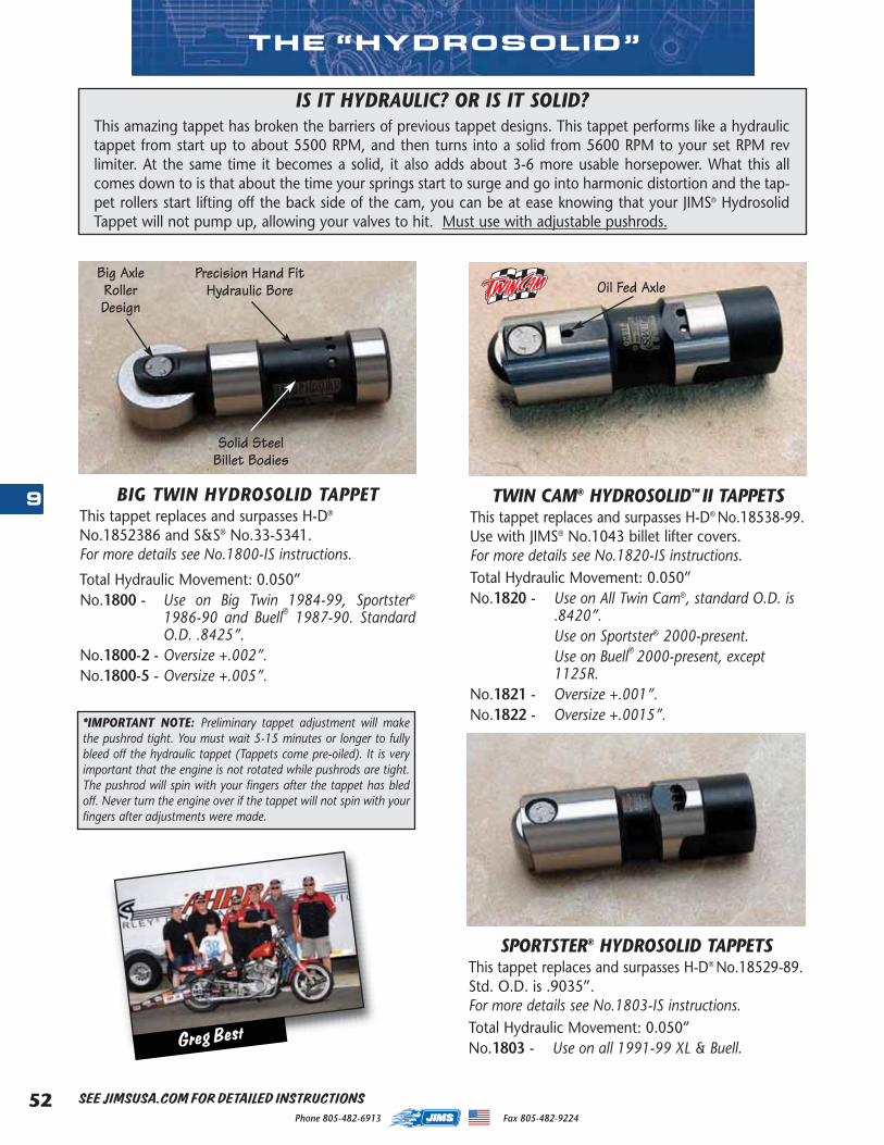
Phone 805-482-6913 Fax 805-482-922452
9
THE “HYDROSOLID”
IS IT HYDRAULIC? OR IS IT SOLID? This amazing tappet has broken the barriers of previous tappet designs. This tappet performs like a hydraulictappet from start up to about 5500 RPM, and then turns into a solid from 5600 RPM to your set RPM revlimiter. At the same time it becomes a solid, it also adds about 3-6 more usable horsepower. What this allcomes down to is that about the time your springs start to surge and go into harmonic distortion and the tap-pet rollers start lifting off the back side of the cam, you can be at ease knowing that your JIMS® HydrosolidTappet will not pump up, allowing your valves to hit. Must use with adjustable pushrods.
BIG TWIN HYDROSOLID TAPPETThis tappet replaces and surpasses H-D®
No.1852386 and S&S® No.33-5341. For more details see No.1800-IS instructions.
Total Hydraulic Movement: 0.050”No.1800 - Use on Big Twin 1984-99, Sportster®
1986-90 and Buell® 1987-90. StandardO.D. .8425”.
No.1800-2 - Oversize +.002”.No.1800-5 - Oversize +.005”.
TWIN CAM® HYDROSOLID™ II TAPPETSThis tappet replaces and surpasses H-D® No.18538-99.Use with JIMS® No.1043 billet lifter covers. For more details see No.1820-IS instructions.Total Hydraulic Movement: 0.050”No.1820 - Use on All Twin Cam®, standard O.D. is
.8420”.Use on Sportster® 2000-present.Use on Buell® 2000-present, except1125R.
No.1821 - Oversize +.001”.No.1822 - Oversize +.0015”.
Solid SteelBillet Bodies
Precision Hand FitHydraulic Bore
Big AxleRollerDesign
SPORTSTER® HYDROSOLID TAPPETSThis tappet replaces and surpasses H-D® No.18529-89.Std. O.D. is .9035”. For more details see No.1803-IS instructions.Total Hydraulic Movement: 0.050”No.1803 - Use on all 1991-99 XL & Buell.
*IMPORTANT NOTE: Preliminary tappet adjustment will makethe pushrod tight. You must wait 5-15 minutes or longer to fullybleed off the hydraulic tappet (Tappets come pre-oiled). It is veryimportant that the engine is not rotated while pushrods are tight.The pushrod will spin with your fingers after the tappet has bledoff. Never turn the engine over if the tappet will not spin with yourfingers after adjustments were made.
SEE JIMSUSA.COM FOR DETAILED INSTRUCTIONS
Oil Fed Axle
Greg Best
MASTER 2013 CATALOG_JMS 2.qxp:Layout 1 8/2/12 8:26 PM Page 52
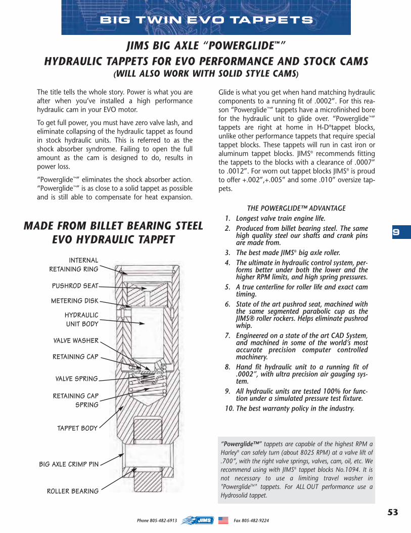
53
9
Phone 805-482-6913 Fax 805-482-9224
“Powerglide™” tappets are capable of the highest RPM aHarley® can safely turn (about 8025 RPM) at a valve lift of.700”, with the right valve springs, valves, cam, oil, etc. Werecommend using with JIMS® tappet blocks No.1094. It isnot necessary to use a limiting travel washer in"PowerglideTM" tappets. For ALL OUT performance use aHydrosolid tappet.
MADE FROM BILLET BEARING STEELEVO HYDRAULIC TAPPET
PUSHROD SEAT
TAPPET BODY
METERING DISK
HYDRAULIC UNIT BODY
RETAINING CAP SPRING
RETAINING CAP
VALVE WASHER
BIG AXLE CRIMP PIN
ROLLER BEARING
VALVE SPRING
INTERNAL RETAINING RING
THE POWERGLIDE™ ADVANTAGE1. Longest valve train engine life.2. Produced from billet bearing steel. The same
high quality steel our shafts and crank pinsare made from.
3. The best made JIMS® big axle roller.4. The ultimate in hydraulic control system, per-
forms better under both the lower and thehigher RPM limits, and high spring pressures.
5. A true centerline for roller life and exact camtiming.
6. State of the art pushrod seat, machined withthe same segmented parabolic cup as theJIMS® roller rockers. Helps eliminate pushrodwhip.
7. Engineered on a state of the art CAD System,and machined in some of the world’s mostaccurate precision computer controlledmachinery.
8. Hand fit hydraulic unit to a running fit of.0002”, with ultra precision air gauging sys-tem.
9. All hydraulic units are tested 100% for func-tion under a simulated pressure test fixture.
10. The best warranty policy in the industry.
BIG TWIN EVO TAPPETS
The title tells the whole story. Power is what you areafter when you’ve installed a high performancehydraulic cam in your EVO motor.
To get full power, you must have zero valve lash, andeliminate collapsing of the hydraulic tappet as foundin stock hydraulic units. This is referred to as theshock absorber syndrome. Failing to open the fullamount as the cam is designed to do, results inpower loss.
“Powerglide™” eliminates the shock absorber action.“Powerglide™” is as close to a solid tappet as possibleand is still able to compensate for heat expansion.
JIMS BIG AXLE “POWERGLIDE™” HYDRAULIC TAPPETS FOR EVO PERFORMANCE AND STOCK CAMS
(WILL ALSO WORK WITH SOLID STYLE CAMS)
Glide is what you get when hand matching hydrauliccomponents to a running fit of .0002”. For this rea-son “Powerglide™” tappets have a microfinished borefor the hydraulic unit to glide over. “Powerglide™”tappets are right at home in H-D®tappet blocks,unlike other performance tappets that require specialtappet blocks. These tappets will run in cast iron oraluminum tappet blocks. JIMS® recommends fittingthe tappets to the blocks with a clearance of .0007”to .0012”. For worn out tappet blocks JIMS® is proudto offer +.002”,+.005” and some .010” oversize tap-pets.
MASTER 2013 CATALOG_JMS 2.qxp:Layout 1 8/2/12 8:26 PM Page 53
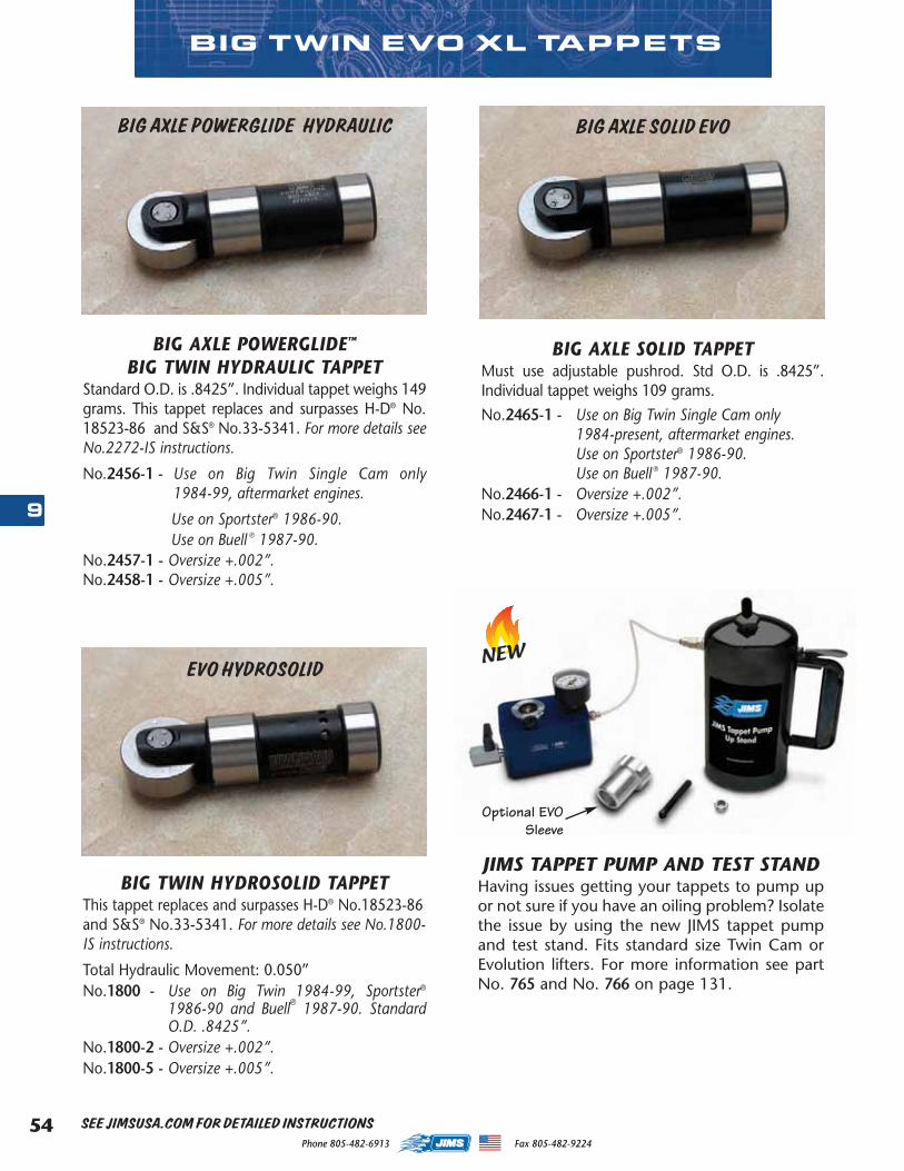
Phone 805-482-6913 Fax 805-482-922454
9
SEE JIMSUSA.COM FOR DETAILED INSTRUCTIONS
BIG AXLE POWERGLIDE HYDRAULIC
BIG AXLE POWERGLIDE™
BIG TWIN HYDRAULIC TAPPETStandard O.D. is .8425”. Individual tappet weighs 149grams. This tappet replaces and surpasses H-D® No.18523-86 and S&S® No.33-5341. For more details seeNo.2272-IS instructions.
No.2456-1 - Use on Big Twin Single Cam only1984-99, aftermarket engines.
Use on Sportster® 1986-90. Use on Buell ® 1987-90.
No.2457-1 - Oversize +.002”.No.2458-1 - Oversize +.005”.
BIG AXLE SOLID TAPPETMust use adjustable pushrod. Std O.D. is .8425”.Individual tappet weighs 109 grams.
No.2465-1 - Use on Big Twin Single Cam only 1984-present, aftermarket engines.Use on Sportster® 1986-90.Use on Buell ® 1987-90.
No.2466-1 - Oversize +.002”.No.2467-1 - Oversize +.005”.
BIG TWIN EVO XL TAPPETS
BIG TWIN HYDROSOLID TAPPETThis tappet replaces and surpasses H-D® No.18523-86and S&S® No.33-5341. For more details see No.1800-IS instructions.
Total Hydraulic Movement: 0.050”No.1800 - Use on Big Twin 1984-99, Sportster®
1986-90 and Buell® 1987-90. StandardO.D. .8425”.
No.1800-2 - Oversize +.002”.No.1800-5 - Oversize +.005”.
EVO HYDROSOLID
BIG AXLE SOLID EVO
Optional EVOSleeve
JIMS TAPPET PUMP AND TEST STAND Having issues getting your tappets to pump upor not sure if you have an oiling problem? Isolatethe issue by using the new JIMS tappet pumpand test stand. Fits standard size Twin Cam orEvolution lifters. For more information see partNo. 765 and No. 766 on page 131.
NEW
MASTER 2013 CATALOG_JMS 2.qxp:Layout 1 8/2/12 8:26 PM Page 54
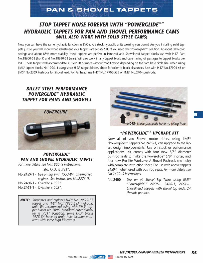
55
9
Phone 805-482-6913 Fax 805-482-9224
PAN & SHOVEL TAPPETS
SEE JIMSUSA.COM FOR DETAILED INSTRUCTIONS
Now you can have the same hydraulic function as EVO’s. Are stock hydraulic units wearing you down? Are you installing solid tap-pets just so you will know what adjustment your tappets are set at? STOP! You need the "PowerglideTM" solution. At about 30% costsavings and about 85% more stability, these tappets are perfect in Panhead and Shovelhead tappet blocks use with H-D® PartNo.18600-53 (front) and No.18610-53 (rear). Will also work in any tappet block and case having oil passages to tappet blocks preEVO. These tappets will accommodate a .550” lift or more without modification depending on the cam base circle size when usingJIMS® tappet blocks No.1095. If using stock H-D® tappet blocks, check for roller to block clearances. Use with H-D® No.17904-66 orJIMS® No.2369 Pushrods for Shovelhead. For Panhead, use H-D® No.17905-53B or JIMS® No.2404 pushrods.
STOP TAPPET NOISE FOREVER WITH “POWERGLIDE™”HYDRAULIC TAPPETS FOR PAN AND SHOVEL PERFORMANCE CAMS
(WILL ALSO WORK WITH SOLID STYLE CAMS)
NOTE: Surpasses and replaces H-D® No.18522-53tappet and H-D® No.17920-53A hydraulicunit. We recommend using with JIMS® tap-pet blocks No.1095. Standard outer diame-ter is .731” (Caution: some H-D® blocks1978-84 have oil drain hole location prob-lems with some high lift cams).
POWERGLIDE™
PAN AND SHOVEL HYDRAULIC TAPPETFor more details see No.1800-IS instructions.
Std. O.D. is .731”.No.2459-1 - Use on Big Twin 1953-84, aftermarket
engines. See Instructions No.2275-IS.No.2460-1 - Oversize +.002”.No.2461-1 - Oversize +.005”.
POWERGLIDE
BILLET STEEL PERFORMANCEPOWERGLIDE™ HYDRAULIC
TAPPET FOR PANS AND SHOVELS
“POWERGLIDE™” UPGRADE KITNow all of you Shovel motor riders, using JIMS®
“Powerglide™” Tappets No.2459-1, can upgrade to the lat-est design improvements. Use on stock or performanceapplications. Kit comes with four new 3/8” diameterpushrod seats to make the Powerglide™ 5/8” shorter, andfour new Pro-Lite Worksavers® Shovel Pushrods (no hole)with complete instruction sheet. For use with above tappets2459-1 when used with pushrod seats. For more details seeNo.2400-IS instructions.
No.2400 - Use on all Shovel Big Twins using JIMS®
“Powerglide™” 2459-1, 2460-1, 2461-1.Shovelhead Tappets with shovel top ends. 24threads per inch.
NOTE: These pushrods have no oiling hole.➦
MASTER 2013 CATALOG_JMS 2.qxp:Layout 1 8/2/12 8:26 PM Page 55
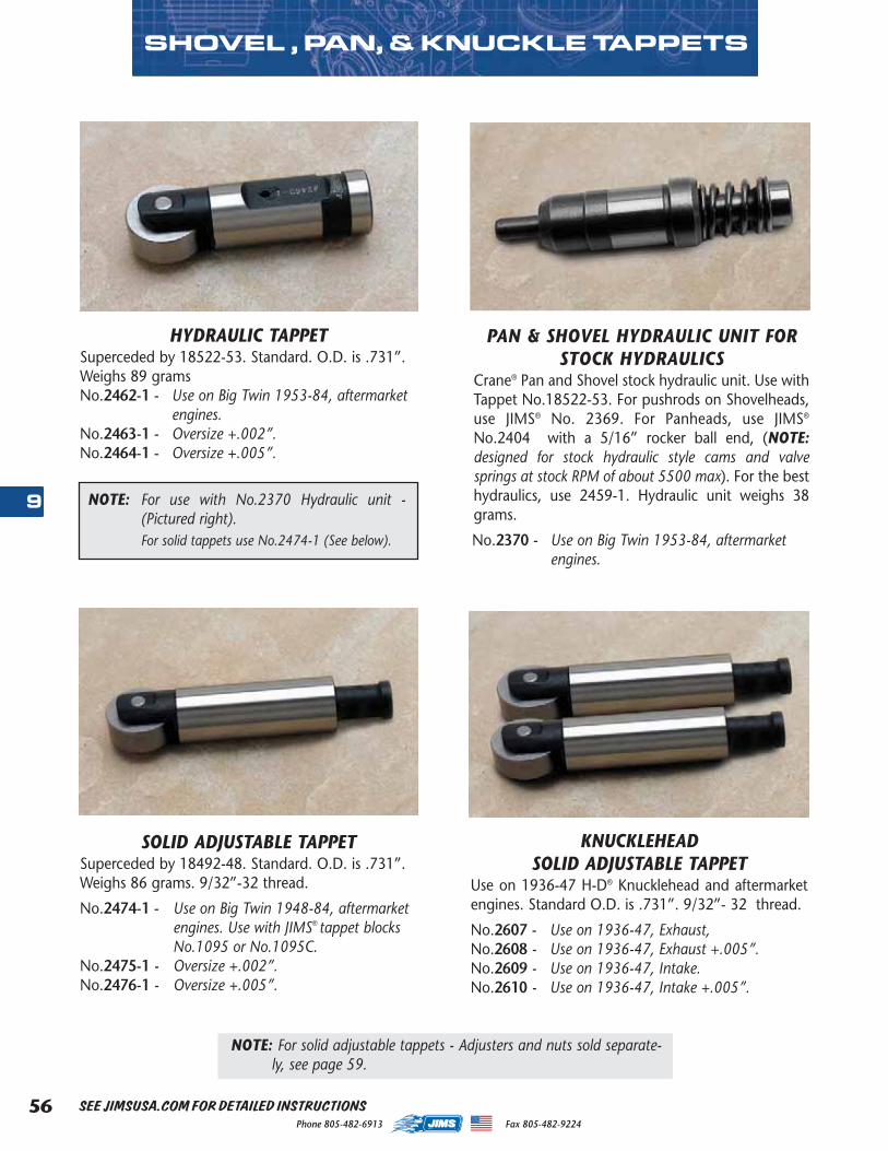
Phone 805-482-6913 Fax 805-482-922456
9
PAN & SHOVEL HYDRAULIC UNIT FORSTOCK HYDRAULICS
Crane® Pan and Shovel stock hydraulic unit. Use withTappet No.18522-53. For pushrods on Shovelheads,use JIMS® No. 2369. For Panheads, use JIMS®
No.2404 with a 5/16” rocker ball end, (NOTE:designed for stock hydraulic style cams and valvesprings at stock RPM of about 5500 max). For the besthydraulics, use 2459-1. Hydraulic unit weighs 38grams.
No.2370 - Use on Big Twin 1953-84, aftermarket engines.
SHOVEL , PAN, & KNUCKLE TAPPETS
NOTE: For solid adjustable tappets - Adjusters and nuts sold separate-ly, see page 59.
HYDRAULIC TAPPETSuperceded by 18522-53. Standard. O.D. is .731”.Weighs 89 gramsNo.2462-1 - Use on Big Twin 1953-84, aftermarket
engines.No.2463-1 - Oversize +.002”.No.2464-1 - Oversize +.005”.
SOLID ADJUSTABLE TAPPETSuperceded by 18492-48. Standard. O.D. is .731”.Weighs 86 grams. 9/32”-32 thread.
No.2474-1 - Use on Big Twin 1948-84, aftermarketengines. Use with JIMS® tappet blocksNo.1095 or No.1095C.
No.2475-1 - Oversize +.002”.No.2476-1 - Oversize +.005”.
KNUCKLEHEAD SOLID ADJUSTABLE TAPPET
Use on 1936-47 H-D® Knucklehead and aftermarketengines. Standard O.D. is .731”. 9/32”- 32 thread.
No.2607 - Use on 1936-47, Exhaust,No.2608 - Use on 1936-47, Exhaust +.005”.No.2609 - Use on 1936-47, Intake.No.2610 - Use on 1936-47, Intake +.005”.
NOTE: For use with No.2370 Hydraulic unit -(Pictured right). For solid tappets use No.2474-1 (See below).
SEE JIMSUSA.COM FOR DETAILED INSTRUCTIONS
MASTER 2013 CATALOG_JMS 2.qxp:Layout 1 8/2/12 8:26 PM Page 56
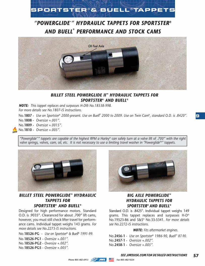
57
9
Phone 805-482-6913 Fax 805-482-9224
“POWERGLIDE™” HYDRAULIC TAPPETS FOR SPORTSTER®
AND BUELL® PERFORMANCE AND STOCK CAMS
BILLET STEEL POWERGLIDE™ HYDRAULICTAPPETS FOR
SPORTSTER® AND BUELL®
Designed for high performance motors. StandardO.D. is .9035”. Clearanced for about .700” lift cams,however, you must still check lifter travel for perform-ance cams. Individual tappet weighs 143 grams. Formore details see No.2273-IS instructions.No.18526-PG - Use on Sportster® & Buell® 1991-99.No.18526-PG1 - Oversize +.001”.No.18526-PG2 - Oversize +.002”.No.18526-PG5 - Oversize +.005”.
SPORTSTER ®& BUELL ®TAPPETS
BIG AXLE POWERGLIDE™
HYDRAULIC TAPPETS FOR SPORTSTER® AND BUELL®
Standard O.D. is .8425”. Individual tappet weighs 149grams. This tappet replaces and surpasses H-D®
No.19523-86 and S&S® No.33-5341. For more detailssee No.2272-IS instructions.
NOTE: Fits aftermarket engines.
No.2456-1 - Use on Sportster® 1986-90, Buell ® 87-90.No.2457-1 - Oversize +.002”.No.2458-1 - Oversize +.005”.
SEE JIMSUSA.COM FOR DETAILED INSTRUCTIONS
BILLET STEEL POWERGLIDE II™ HYDRAULIC TAPPETS FOR SPORTSTER® AND BUELL®
NOTE: This tappet replaces and surpasses H-D® No.18538-99B.For more details see No.1807-IS instructions.No.1807 - Use on Sportster® 2000-present. Use on Buell® 2000 to 2009. Use on Twin Cam®, standard O.D. is .8420”.No.1808 - Oversize +.001”.No.1809 - Oversize +.0015”.No.1810 - Oversize +.005”.
NEW
“Powerglide™” tappets are capable of the highest RPM a Harley® can safely turn at a valve lift of .700” with the rightvalve springs, valves, cam, oil, etc. It is not necessary to use a limiting travel washer in "PowerglideTM" tappets.
Oil Fed Axle
MASTER 2013 CATALOG_JMS 2.qxp:Layout 1 8/2/12 8:26 PM Page 57
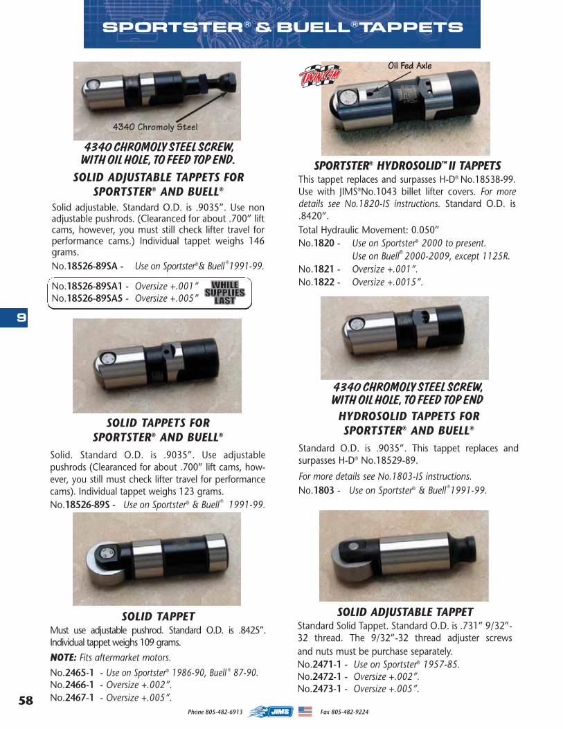
Phone 805-482-6913 Fax 805-482-922458
9
SOLID ADJUSTABLE TAPPETStandard Solid Tappet. Standard O.D. is .731” 9/32”-32 thread. The 9/32”-32 thread adjuster screwsand nuts must be purchase separately.No.2471-1 - Use on Sportster® 1957-85.No.2472-1 - Oversize +.002”.No.2473-1 - Oversize +.005”.
SOLID TAPPETMust use adjustable pushrod. Standard O.D. is .8425”.Individual tappet weighs 109 grams.
NNOTE: Fits aftermarket motors.
No.2465-1 - Use on Sportster® 1986-90, Buell ® 87-90.No.2466-1 - Oversize +.002”.No.2467-1 - Oversize +.005”.
4340 CHROMOLY STEEL SCREW, WITH OIL HOLE, TO FEED TOP END
SPORTSTER® & BUELL®TAPPETS
SOLID TAPPETS FOR SPORTSTER® AND BUELL®
Solid. Standard O.D. is .9035”. Use adjustablepushrods (Clearanced for about .700” lift cams, how-ever, you still must check lifter travel for performancecams). Individual tappet weighs 123 grams.No.18526-89S - Use on Sportster® & Buell ® 1991-99.
HYDROSOLID TAPPETS FORSPORTSTER® AND BUELL®
Standard O.D. is .9035”. This tappet replaces andsurpasses H-D® No.18529-89.
For more details see No.1803-IS instructions.No.1803 - Use on Sportster® & Buell ®1991-99.
SPORTSTER® HYDROSOLID™ II TAPPETSThis tappet replaces and surpasses H-D® No.18538-99.Use with JIMS®No.1043 billet lifter covers. For moredetails see No.1820-IS instructions. Standard O.D. is.8420”.Total Hydraulic Movement: 0.050”No.1820 - Use on Sportster® 2000 to present.
Use on Buell® 2000-2009, except 1125R.No.1821 - Oversize +.001”.No.1822 - Oversize +.0015”.
SOLID ADJUSTABLE TAPPETS FORSPORTSTER® AND BUELL®
Solid adjustable. Standard O.D. is .9035”. Use nonadjustable pushrods. (Clearanced for about .700” liftcams, however, you must still check lifter travel forperformance cams.) Individual tappet weighs 146grams.No.18526-89SA - Use on Sportster®& Buell ®1991-99.
No.18526-89SA1 - Oversize +.001”No.18526-89SA5 - Oversize +.005”
4340 CHROMOLY STEEL SCREW, WITH OIL HOLE, TO FEED TOP END.
4340 Chromoly Steel
Oil Fed Axle
MASTER 2013 CATALOG_JMS 2.qxp:Layout 1 8/2/12 8:26 PM Page 58
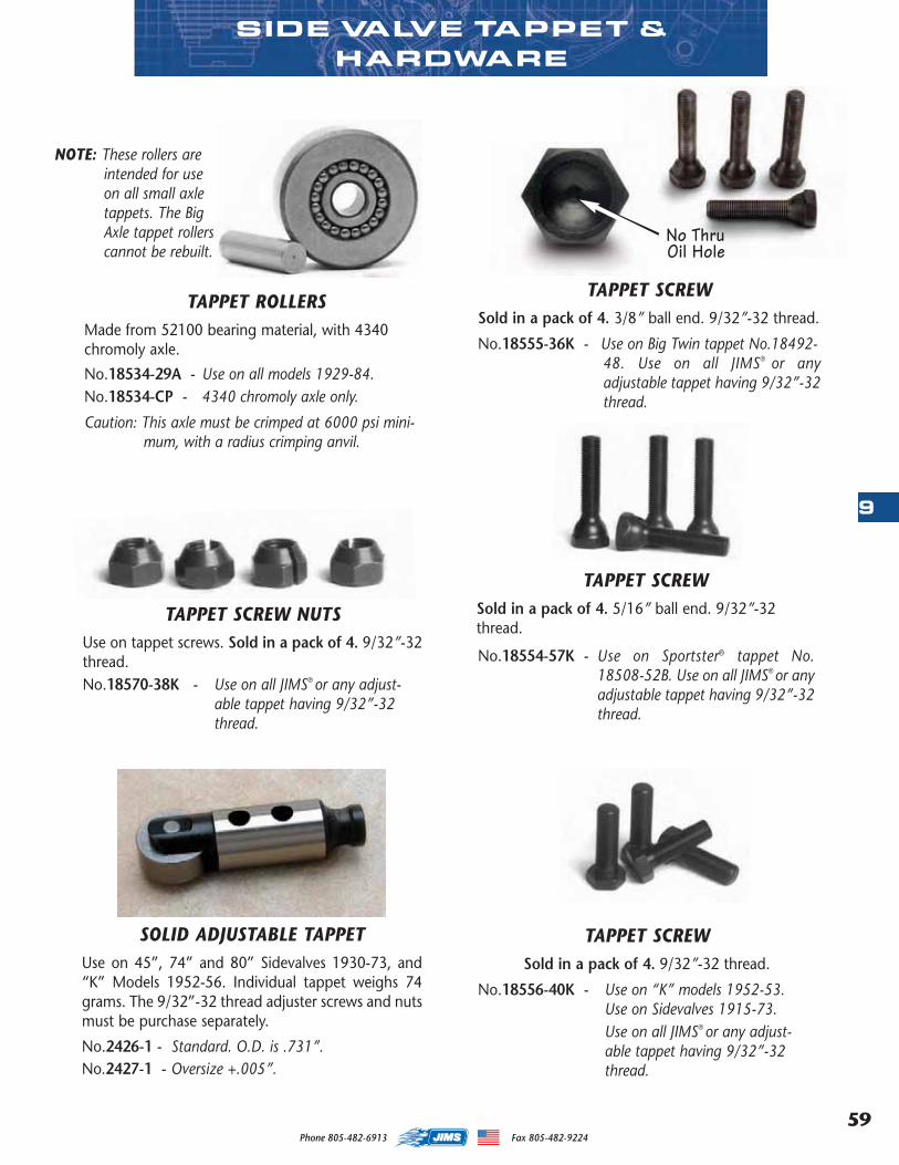
59
9
Phone 805-482-6913 Fax 805-482-9224
TAPPET ROLLERSMade from 52100 bearing material, with 4340chromoly axle.
No.18534-29A - Use on all models 1929-84. No.18534-CP - 4340 chromoly axle only.
Caution: This axle must be crimped at 6000 psi mini-mum, with a radius crimping anvil.
TAPPET SCREW NUTSUse on tappet screws. Sold in a pack of 4. 9/32”-32thread. No.18570-38K - Use on all JIMS® or any adjust-
able tappet having 9/32”-32 thread.
TAPPET SCREWSold in a pack of 4. 5/16” ball end. 9/32”-32thread.
No.18554-57K - Use on Sportster® tappet No.18508-52B. Use on all JIMS® or anyadjustable tappet having 9/32”-32thread.
TAPPET SCREWSold in a pack of 4. 9/32”-32 thread.
No.18556-40K - Use on “K” models 1952-53.Use on Sidevalves 1915-73.Use on all JIMS® or any adjust-able tappet having 9/32”-32 thread.
NOTE: These rollers areintended for useon all small axletappets. The BigAxle tappet rollerscannot be rebuilt.
SIDE VALVE TAPPET & HARDWARE
No ThruOil Hole
TAPPET SCREWSold in a pack of 4. 3/8” ball end. 9/32”-32 thread.
No.18555-36K - Use on Big Twin tappet No.18492-48. Use on all JIMS® or anyadjustable tappet having 9/32”-32thread.
SOLID ADJUSTABLE TAPPETUse on 45”, 74” and 80” Sidevalves 1930-73, and“K” Models 1952-56. Individual tappet weighs 74grams. The 9/32”-32 thread adjuster screws and nutsmust be purchase separately.
No.2426-1 - Standard. O.D. is .731”.No.2427-1 - Oversize +.005”.
MASTER 2013 CATALOG_JMS 2.qxp:Layout 1 8/2/12 8:26 PM Page 59
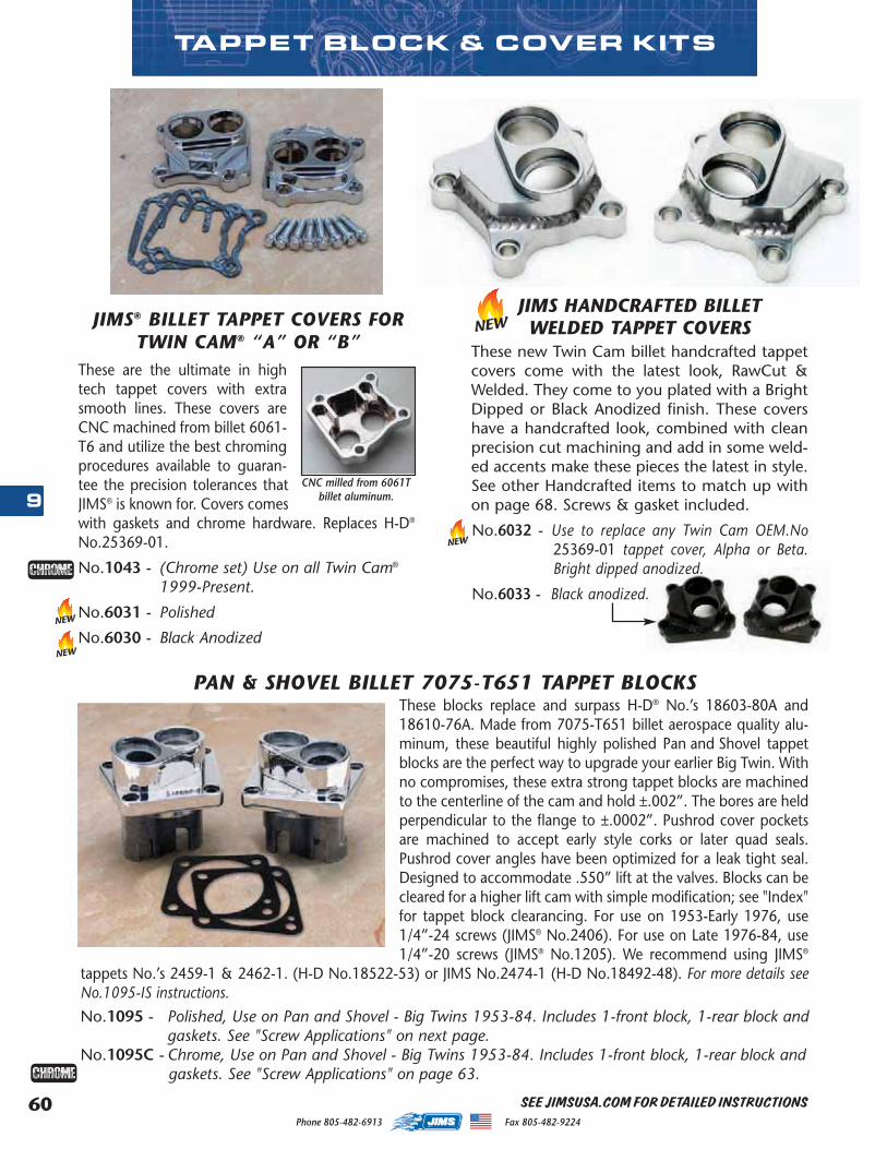
Phone 805-482-6913 Fax 805-482-922460
9
SEE JIMSUSA.COM FOR DETAILED INSTRUCTIONS
PAN & SHOVEL BILLET 7075-T651 TAPPET BLOCKSThese blocks replace and surpass H-D® No.’s 18603-80A and18610-76A. Made from 7075-T651 billet aerospace quality alu-minum, these beautiful highly polished Pan and Shovel tappetblocks are the perfect way to upgrade your earlier Big Twin. Withno compromises, these extra strong tappet blocks are machinedto the centerline of the cam and hold ±.002”. The bores are heldperpendicular to the flange to ±.0002”. Pushrod cover pocketsare machined to accept early style corks or later quad seals.Pushrod cover angles have been optimized for a leak tight seal.Designed to accommodate .550” lift at the valves. Blocks can becleared for a higher lift cam with simple modification; see "Index"for tappet block clearancing. For use on 1953-Early 1976, use1/4”-24 screws (JIMS® No.2406). For use on Late 1976-84, use1/4”-20 screws (JIMS® No.1205). We recommend using JIMS®
tappets No.’s 2459-1 & 2462-1. (H-D No.18522-53) or JIMS No.2474-1 (H-D No.18492-48). For more details seeNo.1095-IS instructions.
No.1095 - Polished, Use on Pan and Shovel - Big Twins 1953-84. Includes 1-front block, 1-rear block andgaskets. See "Screw Applications" on next page.
No.1095C - Chrome, Use on Pan and Shovel - Big Twins 1953-84. Includes 1-front block, 1-rear block andgaskets. See "Screw Applications" on page 63.
JIMS® BILLET TAPPET COVERS FORTWIN CAM® “A” OR “B”
These are the ultimate in hightech tappet covers with extrasmooth lines. These covers areCNC machined from billet 6061-T6 and utilize the best chromingprocedures available to guaran-tee the precision tolerances thatJIMS® is known for. Covers comeswith gaskets and chrome hardware. Replaces H-D®
No.25369-01.
No.1043 - (Chrome set) Use on all Twin Cam®
1999-Present.
No.6031 - Polished
No.6030 - Black Anodized
CNC milled from 6061Tbillet aluminum.
TAPPET BLOCK & COVER KITS
NEWJIMS HANDCRAFTED BILLET WELDED TAPPET COVERS
These new Twin Cam billet handcrafted tappetcovers come with the latest look, RawCut &Welded. They come to you plated with a BrightDipped or Black Anodized finish. These covershave a handcrafted look, combined with cleanprecision cut machining and add in some weld-ed accents make these pieces the latest in style.See other Handcrafted items to match up withon page 68. Screws & gasket included.
No.6032 - Use to replace any Twin Cam OEM.No25369-01 tappet cover, Alpha or Beta.Bright dipped anodized.
No.6033 - Black anodized.
NEW
NEW
NEW
MASTER 2013 CATALOG_JMS 2.qxp:Layout 1 8/2/12 8:26 PM Page 60
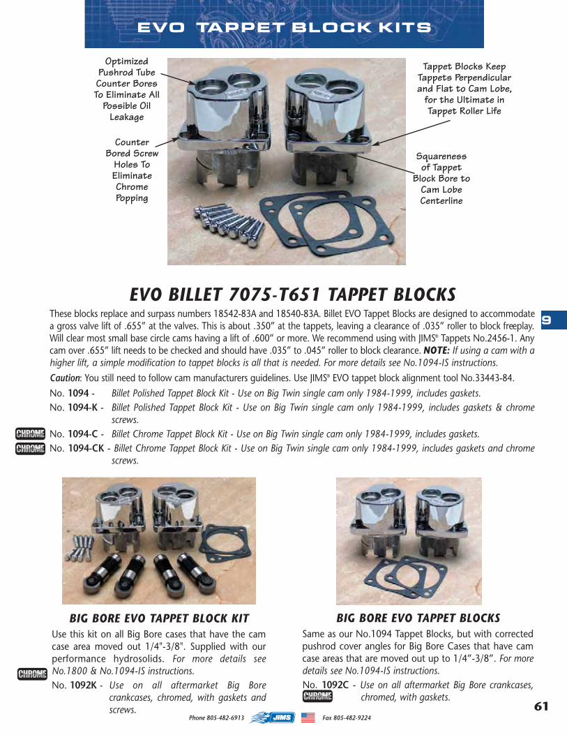
61
9
Phone 805-482-6913 Fax 805-482-9224
EVO BILLET 7075-T651 TAPPET BLOCKSThese blocks replace and surpass numbers 18542-83A and 18540-83A. Billet EVO Tappet Blocks are designed to accommodatea gross valve lift of .655” at the valves. This is about .350” at the tappets, leaving a clearance of .035” roller to block freeplay.Will clear most small base circle cams having a lift of .600” or more. We recommend using with JIMS® Tappets No.2456-1. Anycam over .655” lift needs to be checked and should have .035” to .045” roller to block clearance. NOTE: If using a cam with ahigher lift, a simple modification to tappet blocks is all that is needed. For more details see No.1094-IS instructions.
Caution: You still need to follow cam manufacturers guidelines. Use JIMS® EVO tappet block alignment tool No.33443-84.
No. 1094 - Billet Polished Tappet Block Kit - Use on Big Twin single cam only 1984-1999, includes gaskets.No. 1094-K - Billet Polished Tappet Block Kit - Use on Big Twin single cam only 1984-1999, includes gaskets & chrome
screws.No. 1094-C - Billet Chrome Tappet Block Kit - Use on Big Twin single cam only 1984-1999, includes gaskets.No. 1094-CK - Billet Chrome Tappet Block Kit - Use on Big Twin single cam only 1984-1999, includes gaskets and chrome
screws.
EVO TAPPET BLOCK KITS
BIG BORE EVO TAPPET BLOCK KITUse this kit on all Big Bore cases that have the camcase area moved out 1/4"-3/8". Supplied with ourperformance hydrosolids. For more details seeNo.1800 & No.1094-IS instructions.No. 1092K - Use on all aftermarket Big Bore
crankcases, chromed, with gaskets andscrews.
BIG BORE EVO TAPPET BLOCKSSame as our No.1094 Tappet Blocks, but with correctedpushrod cover angles for Big Bore Cases that have camcase areas that are moved out up to 1/4”-3/8”. For moredetails see No.1094-IS instructions.No. 1092C - Use on all aftermarket Big Bore crankcases,
chromed, with gaskets.
Tappet Blocks KeepTappets Perpendicularand Flat to Cam Lobe,
for the Ultimate inTappet Roller Life
CounterBored Screw
Holes ToEliminateChromePopping
Squarenessof Tappet
Block Bore toCam LobeCenterline
OptimizedPushrod TubeCounter BoresTo Eliminate All
Possible OilLeakage
MASTER 2013 CATALOG_JMS 2.qxp:Layout 1 8/2/12 8:26 PM Page 61
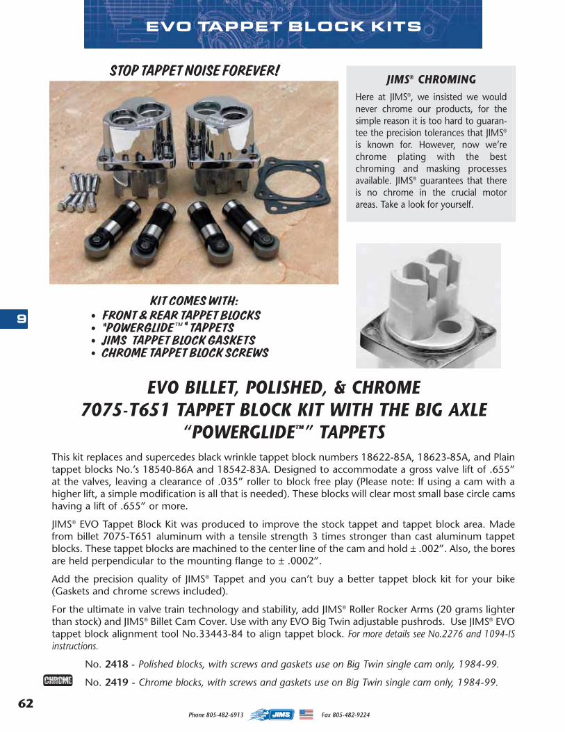
Phone 805-482-6913 Fax 805-482-922462
9
EVO TAPPET BLOCK KITS
KIT COMES WITH:• FRONT & REAR TAPPET BLOCKS • "POWERGLIDE™" TAPPETS• JIMS TAPPET BLOCK GASKETS• CHROME TAPPET BLOCK SCREWS
EVO BILLET, POLISHED, & CHROME7075-T651 TAPPET BLOCK KIT WITH THE BIG AXLE
“POWERGLIDE™” TAPPETSThis kit replaces and supercedes black wrinkle tappet block numbers 18622-85A, 18623-85A, and Plaintappet blocks No.’s 18540-86A and 18542-83A. Designed to accommodate a gross valve lift of .655”at the valves, leaving a clearance of .035” roller to block free play (Please note: If using a cam with ahigher lift, a simple modification is all that is needed). These blocks will clear most small base circle camshaving a lift of .655” or more.
JIMS® EVO Tappet Block Kit was produced to improve the stock tappet and tappet block area. Madefrom billet 7075-T651 aluminum with a tensile strength 3 times stronger than cast aluminum tappetblocks. These tappet blocks are machined to the center line of the cam and hold ± .002”. Also, the boresare held perpendicular to the mounting flange to ± .0002”.
Add the precision quality of JIMS® Tappet and you can’t buy a better tappet block kit for your bike(Gaskets and chrome screws included).
For the ultimate in valve train technology and stability, add JIMS® Roller Rocker Arms (20 grams lighterthan stock) and JIMS® Billet Cam Cover. Use with any EVO Big Twin adjustable pushrods. Use JIMS® EVOtappet block alignment tool No.33443-84 to align tappet block. For more details see No.2276 and 1094-ISinstructions.
No. 2418 - Polished blocks, with screws and gaskets use on Big Twin single cam only, 1984-99.
No. 2419 - Chrome blocks, with screws and gaskets use on Big Twin single cam only, 1984-99.
JIMS® CHROMINGHere at JIMS®, we insisted we wouldnever chrome our products, for thesimple reason it is too hard to guaran-tee the precision tolerances that JIMS®
is known for. However, now we’rechrome plating with the bestchroming and masking processesavailable. JIMS® guarantees that thereis no chrome in the crucial motorareas. Take a look for yourself.
STOP TAPPET NOISE FOREVER!
MASTER 2013 CATALOG_JMS 2.qxp:Layout 1 8/2/12 8:26 PM Page 62
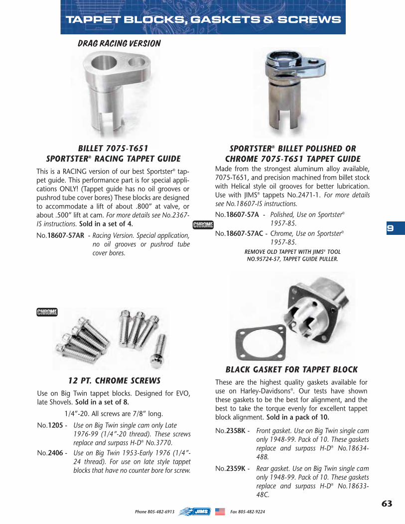
63
9
Phone 805-482-6913 Fax 805-482-9224
SPORTSTER® BILLET POLISHED ORCHROME 7075-T651 TAPPET GUIDE
Made from the strongest aluminum alloy available,7075-T651, and precision machined from billet stockwith Helical style oil grooves for better lubrication.Use with JIMS® tappets No.2471-1. For more detailssee No.18607-IS instructions.
No.18607-57A - Polished, Use on Sportster®
1957-85.No.18607-57AC - Chrome, Use on Sportster®
1957-85.REMOVE OLD TAPPET WITH JIMS® TOOL NO.95724-57, TAPPET GUIDE PULLER.
DRAG RACING VERSION
BLACK GASKET FOR TAPPET BLOCKThese are the highest quality gaskets available foruse on Harley-Davidsons®. Our tests have shownthese gaskets to be the best for alignment, and thebest to take the torque evenly for excellent tappetblock alignment. Sold in a pack of 10.
No.2358K - Front gasket. Use on Big Twin single camonly 1948-99. Pack of 10. These gasketsreplace and surpass H-D® No.18634-48B.
No.2359K - Rear gasket. Use on Big Twin single camonly 1948-99. Pack of 10. These gasketsreplace and surpass H-D® No.18633-48C.
BILLET 7075-T651 SPORTSTER® RACING TAPPET GUIDE
This is a RACING version of our best Sportster® tap-pet guide. This performance part is for special appli-cations ONLY! (Tappet guide has no oil grooves orpushrod tube cover bores) These blocks are designedto accommodate a lift of about .800” at valve, orabout .500” lift at cam. For more details see No.2367-IS instructions. Sold in a set of 4.
No.18607-57AR - Racing Version. Special application,no oil grooves or pushrod tubecover bores.
TAPPET BLOCKS, GASKETS & SCREWS
12 PT. CHROME SCREWSUse on Big Twin tappet blocks. Designed for EVO,late Shovels. Sold in a set of 8.
1/4”-20. All screws are 7/8” long.
No.1205 - Use on Big Twin single cam only Late 1976-99 (1/4”-20 thread). These screwsreplace and surpass H-D® No.3770.
No.2406 - Use on Big Twin 1953-Early 1976 (1/4”-24 thread). For use on late style tappetblocks that have no counter bore for screw.
MASTER 2013 CATALOG_JMS 2.qxp:Layout 1 8/2/12 8:26 PM Page 63

Phone 805-482-6913 Fax 805-482-922464
9
SEE JIMSUSA.COM FOR DETAILED INSTRUCTIONS
PAN & SHOVEL TAPPET BLOCK KITS
PAN AND SHOVEL "POWERGLIDE™" BILLET 7075-T651 TAPPET BLOCK KIT
• .761” diameter tappets not interchangeable with stock diameter (.731”) tappets or blocks.
• Pan and Shovel "Powerglide™" Tappet Block Kits are capable of the highest RPM a Harley® cansafely turn, at a valve lift of .700” with the right valve springs, valves, cam, oil, etc.
• Pan and Shovel motors can have all the hydraulic benefits of the late EVO style hydraulicsystem by installing JIMS® Shovel "Powerglide™" Hydraulic Tappets.
• These kits will eliminate the total oil loss of the stock hydraulic units, No.17920-53A.
• Billet Pan and Shovel Tappet Blocks with "Powerglide™" Hydraulic Tappets. Total Hydraulic Lift: 0.100”.
• Comes complete with instructions.• Tappet block gaskets included.
These tappet blocks replace and surpass lifter block No’s. 18603-80A, 18610-76A and tappet No.’s.18522-53A. Fits Pan and Shovel Big Twins 1953 through 1984. Use 1/4”-20 screws, JIMS® No.1205,from late 1976 through 1984. Use 1/4”-24 screws, JIMS® No.2406, from 1953 through early 1976.These blocks are designed to accommodate a gross valve lift of .550” at the valves, leaving a clearanceof .035” roller to block freeplay (Please note, if using a cam with a higher lift, a simple modification isall that is needed). See page 61 for tappet block clearancing. Use with JIMS® pushrod No.2369 forShovelheads, or No.2404 for Panheads, or equivalent. Blocks can be cleared for higher cam lift.
All JIMS® Billet Polished Tappet Blocks are made from 7075-T651 aluminum with a tensile strength of83,000 psi, which is double the amount of 6061-T6 aluminum and almost triple the amount of cast alu-minum tappet blocks. These tappet blocks are machined to the center line of the cam and hold to±.002”. Also, the bores are held perpendicular to the mounting flange to ±.0002”. (Use quad seals forthe best oil sealants possible.) For more details see No.2274-IS instructions.
No.1029-53B - Polished, with gaskets fits Pan 1953-65 & Shovel Big Twins 1966-84.No.1029-53C - Chrome, with gaskets fits Pan 1953-65 & Shovel Big Twins 1966-84.
KIT COMES WITH:• FRONT & REAR TAPPET
BLOCKS • "POWERGLIDE™" TAPPETS• JIMS TAPPET BLOCK
GASKETS
REPLACEMENT TAPPETSNo.1029ACAB - Standard replacement tappetNo.1029ACAB2 - .002” Oversize replacement tappetNo.1029ACAB5 - .005” Oversize replacement tappet
MASTER 2013 CATALOG_JMS 2.qxp:Layout 1 8/2/12 8:26 PM Page 64
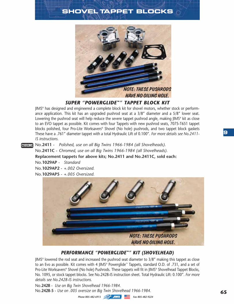
65
9
Phone 805-482-6913 Fax 805-482-9224
PERFORMANCE “POWERGLIDE™” KIT (SHOVELHEAD)JIMS® lowered the rod seat and increased the pushrod seat diameter to 3/8” making this tappet as closeto an Evo as possible. Kit comes with 4 JIMS® Powerglide™ Tappets, standard O.D. of .731, and a set ofPro-Lite Worksavers® Shovel (No hole) Pushrods. These tappets will fit in JIMS® Shovelhead Tappet Blocks,No. 1095, or stock tappet blocks. See No.2428-IS instruction sheet. Total Hydraulic Lift: 0.100”. For moredetails see No.2428-IS instructions.No.2428 - Use on Big Twin Shovelhead 1966-1984.No.2428-5 - Use on .005 oversize on Big Twin Shovelhead 1966-1984.
SUPER “POWERGLIDE™” TAPPET BLOCK KITJIMS® has designed and engineered a complete block kit for shovel motors, whether stock or perform-ance application. This kit has an upgraded pushrod seat at a 3/8” diameter and a 5/8” lower seat.Lowering the pushrod seat will help reduce the severe tappet pushrod angle, making JIMS® kit as closeto an EVO tappet as possible. Kit comes with four Tappets with new pushrod seats, 7075-T651 tappetblocks polished, four Pro-Lite Worksavers® Shovel (No hole) pushrods, and two tappet block gasketsThese have a .761” diameter tappet with a total Hydraulic Lift of 0.100”. For more details see No.2411-IS instructions.No.2411 - Polished, use on all Big Twins 1966-1984 (all Shovelheads).No.2411C - Chromed, use on all Big Twins 1966-1984 (all Shovelheads).Replacement tappets for above kits; No.2411 and No.2411C, sold each:No.1029AP - StandardNo.1029AP2 - +.002 Oversized.No.1029AP5 - +.005 Oversized.
NOTE: THESE PUSHRODSHAVE NO OILING HOLE.
NOTE: THESE PUSHRODSHAVE NO OILING HOLE.
SHOVEL TAPPET BLOCKS
MASTER 2013 CATALOG_JMS 2.qxp:Layout 1 8/2/12 8:26 PM Page 65
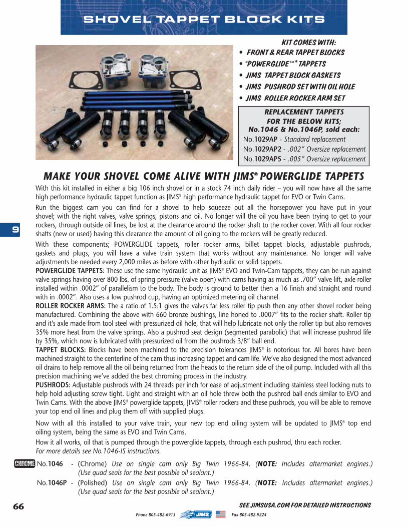
Phone 805-482-6913 Fax 805-482-922466
9
SHOVEL TAPPET BLOCK KITS
KIT COMES WITH:• FRONT & REAR TAPPET BLOCKS • "POWERGLIDE™" TAPPETS• JIMS TAPPET BLOCK GASKETS• JIMS PUSHROD SET WITH OIL HOLE• JIMS ROLLER ROCKER ARM SET
REPLACEMENT TAPPETSFOR THE BELOW KITS;
No.1046 & No.1046P, sold each:No.1029AP - Standard replacementNo.1029AP2 - .002” Oversize replacementNo.1029AP5 - .005” Oversize replacement
MAKE YOUR SHOVEL COME ALIVE WITH JIMS® POWERGLIDE TAPPETS
No.1046 - (Chrome) Use on single cam only Big Twin 1966-84. (NOTE: Includes aftermarket engines.)(Use quad seals for the best possible oil sealant.)
No.1046P - (Polished) Use on single cam only Big Twin 1966-84. (NOTE: Includes aftermarket engines.)(Use quad seals for the best possible oil sealant.)
With this kit installed in either a big 106 inch shovel or in a stock 74 inch daily rider – you will now have all the samehigh performance hydraulic tappet function as JIMS® high performance hydraulic tappet for EVO or Twin Cams.Run the biggest cam you can find for a shovel to help squeeze out all the horsepower you have put in yourshovel; with the right valves, valve springs, pistons and oil. No longer will the oil you have been trying to get to yourrockers, through outside oil lines, be lost at the clearance around the rocker shaft to the rocker cover. With all four rockershafts (new or used) having this clearance the amount of oil going to the rockers will be greatly reduced. With these components; POWERGLIDE tappets, roller rocker arms, billet tappet blocks, adjustable pushrods,gaskets and plugs, you will have a valve train system that works without any maintenance. No longer will valveadjustments be needed every 2,000 miles as before with other hydraulic or solid tappets.POWERGLIDE TAPPETS: These use the same hydraulic unit as JIMS® EVO and Twin-Cam tappets, they can be run againstvalve springs having over 800 lbs. of spring pressure (valve open) with cams having as much as .700” valve lift, axle rollerinstalled within .0002” of parallelism to the body. The body is ground to better then a 16 finish and straight and roundwith in .0002”. Also uses a low pushrod cup, having an optimized metering oil channel. ROLLER ROCKER ARMS: The a ratio of 1.5:1 gives the valves far less roller tip push then any other shovel rocker beingmanufactured. Combining the above with 660 bronze bushings, line honed to .0007” fits to the rocker shaft. Roller tipand it’s axle made from tool steel with pressurized oil hole, that will help lubricate not only the roller tip but also removes35% more heat from the valve springs. Also a pushrod seat design (segmented parabolic) that will increase pushrod lifeby 35%, which now is lubricated with pressurized oil from the pushrods 3/8” ball end.TAPPET BLOCKS: Blocks have been machined to the precision tolerances JIMS® is notorious for. All bores have beenmachined straight to the centerline of the cam thus increasing tappet and cam life. We’ve also designed the most advancedoil drains to help remove all the oil being returned from the heads to the return side of the oil pump. Included with all thisprecision machining we’ve added the best chroming process in the industry.PUSHRODS: Adjustable pushrods with 24 threads per inch for ease of adjustment including stainless steel locking nuts tohelp hold adjusting screw tight. Light and straight with an oil hole threw both the pushrod ball ends similar to EVO andTwin Cams. With the above JIMS® powerglide tappets, JIMS® roller rockers and these pushrods, you will be able to removeyour top end oil lines and plug them off with supplied plugs.
Now with all this installed to your valve train, your new top end oiling system will be updated to JIMS® top endoiling system, being the same as EVO and Twin Cams.How it all works, oil that is pumped through the powerglide tappets, through each pushrod, thru each rocker. For more details see No.1046-IS instructions.
SEE JIMSUSA.COM FOR DETAILED INSTRUCTIONS
MASTER 2013 CATALOG_JMS 2.qxp:Layout 1 8/2/12 8:26 PM Page 66
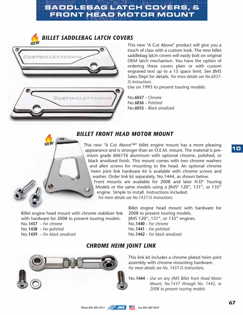
67
10
Phone 805-482-6913 Fax 805-482-9224
This new "A Cut Above™" billet engine mount has a more pleasingappearance and is stronger than an O.E.M. mount. The material is pre-mium grade 6061T6 aluminum with optional chrome, polished, orblack anodized finish. This mount comes with two chrome washersand allen screws for mounting to the head. An optional chromeheim joint link hardware kit is available with chrome screws andwasher. Order link kit separately, No.1444, as shown below.Front mounts are available for 2008 and later H-D® TouringModels or the same models using a JIMS® 120”, 131”, or 135”engine. Simple to install. Instructions included. For more details see No.1437-IS instructions.
Billet engine head mount with chrome stabilizer link with hardware for 2008 to present touring models:No.1437 - For chrome No.1438 - For polishedNo.1439 - For black anodized
SADDLEBAG LATCH COVERS, &FRONT HEAD MOTOR MOUNT
BILLET FRONT HEAD MOTOR MOUNT
BILLET SADDLEBAG LATCH COVERSThis new "A Cut Above" product will give you atouch of class with a custom look. The new billetsaddlebag latch covers will easily bolt on originalOEM latch mechanism. You have the option ofordering these covers plain or with customengraved text up to a 15 space limit. See JIMSSales Dept for details. For more details see No.6037-IS instructions. Use on 1993 to present touring models:
No.6037 - ChromeNo.6036 - PolishedNo.6035 - Black anodized
Billet engine head mount with hardware for2008 to present touring models. JIMS 120”, 131”, or 135” engines.No.1440 - For chromeNo.1441 - For polishedNo.1442 - For black anodized
CHROME HEIM JOINT LINK
This link kit includes a chrome plated heim jointassembly with chrome mounting hardware. For more details see No. 1437-IS instructions.
No.1444 - Use on any JIMS Billet front Head MotorMount, No.1437 through No. 1442, or2008 to present touring models.
NEW
NEW
MASTER 2013 CATALOG_JMS 2.qxp:Layout 1 8/2/12 8:26 PM Page 67

Phone 805-482-6913 Fax 805-482-922468
11
JIMS HANDCRAFTED TRANSMISSION SIDE COVERThese new billet transmission side covers come with the latest look, RawCut & Welded. They come
to you plated with a Bright Dipped or Black Anodized finish. The cover has a handcraftedlook, combined with a clean precision cut fin pack, and add in some welded accentsmaking these pieces the latest in style. Order a JIMS Cam cover No. 2300 to matchup with and you'll be No. 1. Screws & gasket included.
No. 2395 - Use on all 2006 to present H-D Cruise Drive 6-speed transmissions.Bright Dipped Anodized.
No. 2396 - Black Anodized.
No. 2394 - Use on all 1987 to 2006 Big Twin 5-Speed transmissions and aftermarket6-speeds with a minor hardware change. (Not for FXR with controls.) BrightDipped Anodized.
No. 2398 - Black Anodized.
NEW
WELDED CAM COVER, TAPPETBLOCKS, & TRANS SIDE COVER
JIMS HANDCRAFTED COVERSPicture this...Just over a year ago, Jim walking through a custom car show, downtown Ventura, CA.A handcrafted oil pan with skilled welds catches his eye. One year later, JIMS® hasintegrated a precision machined set of covers to outfit your late model HD withthis latest new look - RawCut & Welded. Plating is a Bright DippedAnodized. These are the same precision machined billet covers youwould expect from JIMS - just hand welded. When combined withJIMS tappet covers, and a JIMS pushrod tube cover set these newJIMS covers will update your bike to a tough new handcrafted look.Screws & gasket included.No. 2300 - Use on 2001 to present Twin Cam models. Bright Dipped Anodized.No. 2301 - Black Anodized.
JIMS HANDCRAFTED BILLET WELDED TAPPET COVERSThese new Twin Cam billet handcrafted tappet covers come withthe latest look, RawCut & Welded. They come to you plated witha Bright Dipped or Black Anodized finish. These covers have a hand-crafted look, combined with clean precision cut machining, and addin some welded accents to make these pieces the latest in style. Screws & gasket included. Use to replace any TC OEM.No 25369-01 tappet cover.No. 6032 - Alpha or Beta Bright Dipped Anodized.No. 6033 - Black Anodized.
NEW
BILLET TWIN CAM OR EVO PUSHROD COVER SETThese "A Cut Above" billet pushrod covers are styled to give you a clean andsmooth look. They feature a unique clip that looks like a complete tube whileretaining the simple push-pull spring type function. Will work on any lengthcylinders utilizing spacer kits that are available below. NOTE: Will not fit JIMS stro-ker kit cylinders. For more details see No.3001-IS instructions.TWIN CAM EVOLUTIONNo.3000 - Bright Dipped Anodized. No.3002 - Chrome.No.3003 - Black Anodized. No.3001 - Polished.No.3004 - Chrome.No.3005 - Polished.
NEW
NEW
Black
Black
Black
Black
MASTER 2013 CATALOG_JMS 2.qxp:Layout 1 8/2/12 8:27 PM Page 68
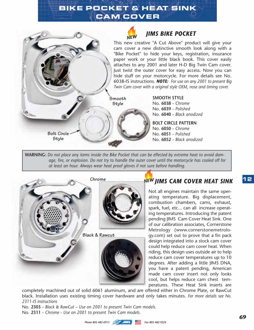
69
12
Phone 805-482-6913 Fax 805-482-9224
This new creative "A Cut Above" product will give yourcam cover a new distinctive smooth look along with a"Bike Pocket" to hide your keys, registration, insurancepaper work or your little black book. This cover easilyattaches to any 2001 and later H-D Big Twin Cam cover.Just twist the outer cover for easy access. Now you canhide stuff on your motorcycle. For more details see No.6038-IS instructions. NOTE: For use on any 2001 to present BigTwin Cam cover with a original style OEM, nose and timing cover.
SMOOTH STYLENo. 6038 - Chrome No. 6039 - PolishedNo. 6040 - Black anodized
BOLT CIRCLE PATTERNNo. 6050 - Chrome No. 6051 - PolishedNo. 6052 - Black anodized
JIMS BIKE POCKETNEW
BIKE POCKET & HEAT SINK CAM COVER
JIMS CAM COVER HEAT SINK
WARNING: Do not place any items inside the Bike Pocket that can be effected by extreme heat to avoid dam-age, fire, or explosion. Do not try to handle the outer cover until the motorcycle has cooled off forat least an hour. Always wear heat proof gloves if not sure before handling.
Not all engines maintain the same oper-ating temperature. Big displacement,combustion chambers, cams, exhaust,spark, fuel, etc... can all increase operat-ing temperatures. Introducing the patentpending JIMS Cam Cover Heat Sink. Oneof our calibration associates, CornerstoneMetrology (www.cornerstonemetrolo-gy.com) set out to prove that a fin packdesign integrated into a stock cam covercould help reduce cam cover heat. Whenriding, this design uses outside air to helpreduce cam cover temperatures up to 10degrees. After adding a little JIMS DNA,you have a patent pending, Americanmade cam cover insert not only lookscool, but helps reduce cam chest tem-peratures. These Heat Sink inserts are
completely machined out of solid 6061 aluminum, and are offered either in Chrome Plate, or RawCutblack. Installation uses existing timing cover hardware and only takes minutes. For more details see No.2311-IS instructionsNo. 2303 - Black & RawCut – Use on 2001 to present Twin Cam models.No. 2311 - Chrome - Use on 2001 to present Twin Cam models.
SmoothStyle
Bolt CircleStyle
NEWChrome
Black & Rawcut
MASTER 2013 CATALOG_JMS 2.qxp:Layout 1 8/2/12 8:27 PM Page 69

Phone 805-482-6913 Fax 805-482-922470
12
JIMS® BILLET & CHROMED BILLET POINTS COVER
Replaces H-D® No.32524-83. Use on Big Twin single cam 1970-present, Sportster® 1971-present and Buell® 1987-present. .190” thick polished 6061-T6 aluminum points cover.Covers come with JIMS® logo lasered on the face or plain. Two chrome flat head allenscrews and gasket included.
No.2239 - Plain polished. Use on Big Twin (Single Cam) and Sportster®.No.2239C - Plain chrome. Use on all Big Twin (Single Cam) and Sportster®.No.2239L - Polished, JIMS® logo. Use on Big Twin (Single Cam).No.2239LC - Chrome, JIMS® logo. Use on Big Twin (Single Cam).
Made from 7075-T651 aluminum with a tensile strength of83,000 PSI, which is double the amount of 6061-T6 alu-minum and almost triple the amount of cast cam covers.This cam cover is positioned precisely to the centerline ofthe cam bushing and pinion bushing. In fact, this cam coveris within .0002” of where the factory intended it to be.
Why hold centerline that close, or why even care about cen-terline in a cam cover? We at JIMS® are concerned with thelife of your motor. For this reason, we are helping you toachieve longer life for your valve train components, consist-ing of your cam, tappets and your tappet blocks.
Your camshaft must lie on the best possible foundation. The foundation we are concerned with is thecenterline of the camshaft. If the camshaft is tilted off in any direction much more than the running clear-ance at each end of the camshaft, this will affect the way the tappet rollers ride on the cam lobe. If theyare not riding flat, but on one edge of the roller, it could possibly shorten the life of your valve train. Thecamshaft is supported at both ends, while the inner cam bearing is a given. This means, the bearing isnot going to move unless you do a lot of machining. Your cam cover must be right to the case center-line for the longest possible tappet and cam life. For early 73 to 92 cam covers see 25258-IS instructionsor for late 93-99 use 25254-IS for more details.
“A CUT ABOVE™” POLISHED OR CHROME BILLET CAM COVERS
CAM COVERSNo.25258-80A - Polished - Use on Big Twin single cam only 1973-92. (NOTE: Includes aftermarket engines.)No.2413 - Chrome - Use on Big Twin single cam only 1973-92. (NOTE: Includes aftermarket engines.)
No.25254-93A - Polished - Use on Big Twin single cam only 1993-99. (NOTE: Includes aftermarket engines.)No.2414 - Chrome - Use on Big Twin single cam only 1993-99. (NOTE: Includes aftermarket engines.)
BACKSIDE OF JIMS® CAM COVER73-92 STYLE COVER
POINTS COVER AND CAM COVER BASE GASKET INCLUDED
SolidBronze
Bushings
Machined ToMaintainFactory
CenterlinesFor PerfectCam/PinionAlignment
2-PieceDesign
IncludesGaskets& Points
Cover
The PerfectCenterline
EVO CAM COVERS
PARTS AVAILABLE SEPARATELY
NO. QTY. DESCRIPTION PART NO.
1 1 CAM COVER OUTER - REP. 25258-80AC 2412
1 1 CAM COVER OUTER - CHROME 2521
2 1 BASE PLATE - EARLY 2522
2 1 BASE PLATE - EARLY CHROME 2524
2 1 BASE PLATE - LATE 2518
2 1 BASE PLATE - LATE CHROME 2525
4 1 SEAL CAM - USE ON 1970-PRESENT 2169REP. H-D® NO.83162-51 (SINGLE CAM)
5 1 O-RING SMALL 2170
6 1 O-RING LARGE 2171
7 2 SOCKET HEAD CAP SCREW LONG 1-1/2” 2027
8 8 SOCKET HEAD CAP SCREW SHORT 1-1/8” 2028
MASTER 2013 CATALOG_JMS 2.qxp:Layout 1 8/2/12 8:27 PM Page 70
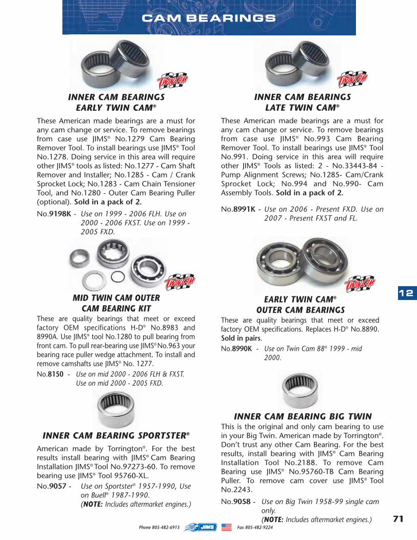
71
12
Phone 805-482-6913 Fax 805-482-9224
CAM BEARINGS
INNER CAM BEARING SPORTSTER®
American made by Torrington®. For the bestresults install bearing with JIMS® Cam BearingInstallation JIMS® Tool No.97273-60. To removebearing use JIMS® Tool 95760-XL.No.9057 - Use on Sportster® 1957-1990, Use
on Buell® 1987-1990. (NOTE: Includes aftermarket engines.)
INNER CAM BEARINGSEARLY TWIN CAM®
These American made bearings are a must forany cam change or service. To remove bearingsfrom case use JIMS® No.1279 Cam BearingRemover Tool. To install bearings use JIMS® ToolNo.1278. Doing service in this area will requireother JIMS® tools as listed: No.1277 - Cam ShaftRemover and Installer; No.1285 - Cam / CrankSprocket Lock; No.1283 - Cam Chain TensionerTool, and No.1280 - Outer Cam Bearing Puller(optional). Sold in a pack of 2.
No.9198K - Use on 1999 - 2006 FLH. Use on2000 - 2006 FXST. Use on 1999 -2005 FXD.
INNER CAM BEARINGS LATE TWIN CAM®
These American made bearings are a must forany cam change or service. To remove bearingsfrom case use JIMS® No.993 Cam BearingRemover Tool. To install bearings use JIMS® ToolNo.991. Doing service in this area will requireother JIMS® Tools as listed: 2 - No.33443-84 -Pump Alignment Screws; No.1285- Cam/CrankSprocket Lock; No.994 and No.990- CamAssembly Tools. Sold in a pack of 2.
No.8991K - Use on 2006 - Present FXD. Use on2007 - Present FXST and FL.
INNER CAM BEARING BIG TWINThis is the original and only cam bearing to usein your Big Twin. American made by Torrington®.Don’t trust any other Cam Bearing. For the bestresults, install bearing with JIMS® Cam BearingInstallation Tool No.2188. To remove CamBearing use JIMS® No.95760-TB Cam BearingPuller. To remove cam cover use JIMS® ToolNo.2243.
No.9058 - Use on Big Twin 1958-99 single cam only. (NOTE: Includes aftermarket engines.)
MID TWIN CAM OUTER CAM BEARING KIT
These are quality bearings that meet or exceedfactory OEM specifications H-D® No.8983 and8990A. Use JIMS® tool No.1280 to pull bearing fromfront cam. To pull rear-bearing use JIMS® No.963 yourbearing race puller wedge attachment. To install andremove camshafts use JIMS® No. 1277.No.8150 - Use on mid 2000 - 2006 FLH & FXST.
Use on mid 2000 - 2005 FXD.
EARLY TWIN CAM®
OUTER CAM BEARINGS These are quality bearings that meet or exceedfactory OEM specifications. Replaces H-D® No.8890.Sold in pairs.No.8990K - Use on Twin Cam 88® 1999 - mid
2000.
MASTER 2013 CATALOG_JMS 2.qxp:Layout 1 8/2/12 8:27 PM Page 71
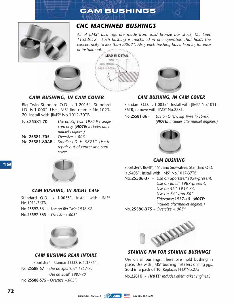
Phone 805-482-6913 Fax 805-482-922472
12
CAM BUSHINGS
CAM BUSHING, IN CAM COVERStandard O.D. is 1.0035”. Install with JIMS® No.1011-36TB, remove with JIMS® No.2281.
No.25581-36 - Use on O.H.V. Big Twin 1936-69. (NOTE: Includes aftermarket engines.)
All of JIMS® bushings are made from solid bronze bar stock, Mil Spec11553C12. Each bushing is machined in one operation that holds theconcentricity to less than .0002”. Also, each bushing has a lead in, for easeof installment.
CNC MACHINED BUSHINGS
CAM BUSHING, IN CAM COVERBig Twin Standard O.D. is 1.2015”. StandardI.D. is 1.000”. Use JIMS® line reamer No.1023-70. Install with JIMS® No.1012-70TB.
No.25581-70 - Use on Big Twin 1970-99 singlecam only. (NOTE: Includes after-market engines.)
No.25581-705 - Oversize +.005”No.25581-80AB - Smaller I.D. is .9875”. Use to
repair out of center line cam cover.
CAM BUSHING, IN RIGHT CASEStandard O.D. is 1.0035”. Install with JIMS®
No.1011-36TB.No.25597-36 - Use on Big Twin 1936-57.No.25597-365 - Oversize +.005”
STAKING PIN FOR STAKING BUSHINGSUse on all bushings. These pins hold bushing inplace. Use with JIMS® bushing installers drilling jigs.Sold in a pack of 10. Replaces H-D®No.275.
No.2201K - (NOTE: Includes aftermarket engines.)
CAM BUSHINGSportster®, Buell®, 45”, and Sidevalves. Standard O.D.is .9405”. Install with JIMS® No.1017-37TB.No.25586-37 - Use on Sportster®1954-present.
Use on Buell® 1987-present.Use on 45” 1937-73. Use on 74” and 80”Sidevalves1937-48. (NOTE:Includes aftermarket engines.)
No.25586-375 - Oversize +.005”
CAM BUSHING REAR INTAKESportster® - Standard O.D. is 1.3775”.
No.25588-57 - Use on Sportster® 1957-90.Use on Buell® 1987-90
No.25588-575 - Oversize +.005”.
MASTER 2013 CATALOG_JMS 2.qxp:Layout 1 8/2/12 8:27 PM Page 72
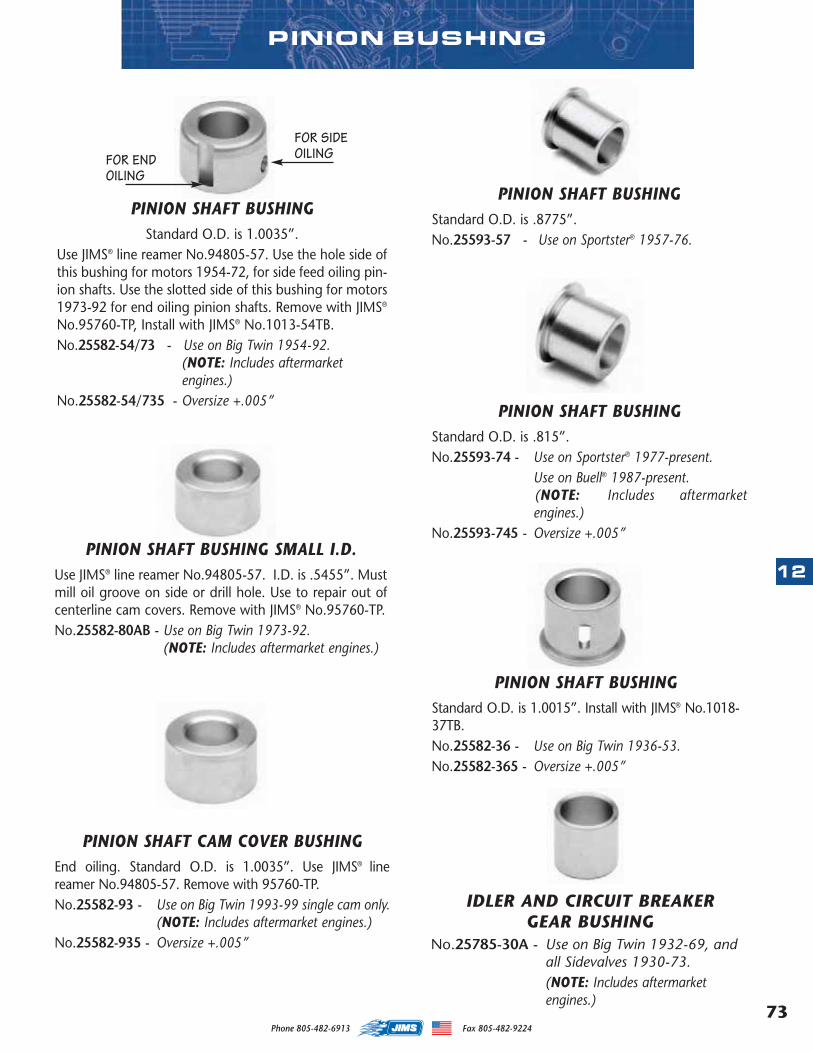
73
12
Phone 805-482-6913 Fax 805-482-9224
PINION SHAFT BUSHINGStandard O.D. is .8775”. No.25593-57 - Use on Sportster® 1957-76.
PINION SHAFT BUSHINGStandard O.D. is .815”. No.25593-74 - Use on Sportster® 1977-present.
Use on Buell® 1987-present.(NOTE: Includes aftermarketengines.)
No.25593-745 - Oversize +.005”
PINION SHAFT BUSHINGStandard O.D. is 1.0015”. Install with JIMS® No.1018-37TB.No.25582-36 - Use on Big Twin 1936-53.No.25582-365 - Oversize +.005”
PINION SHAFT BUSHINGStandard O.D. is 1.0035”.
Use JIMS® line reamer No.94805-57. Use the hole side ofthis bushing for motors 1954-72, for side feed oiling pin-ion shafts. Use the slotted side of this bushing for motors1973-92 for end oiling pinion shafts. Remove with JIMS®
No.95760-TP, Install with JIMS® No.1013-54TB.No.25582-54/73 - Use on Big Twin 1954-92.
(NOTE: Includes aftermarketengines.)
No.25582-54/735 - Oversize +.005”
PINION SHAFT CAM COVER BUSHINGEnd oiling. Standard O.D. is 1.0035”. Use JIMS® linereamer No.94805-57. Remove with 95760-TP.No.25582-93 - Use on Big Twin 1993-99 single cam only.
(NOTE: Includes aftermarket engines.)No.25582-935 - Oversize +.005”
PINION SHAFT BUSHING SMALL I.D.Use JIMS® line reamer No.94805-57. I.D. is .5455”. Mustmill oil groove on side or drill hole. Use to repair out ofcenterline cam covers. Remove with JIMS® No.95760-TP.No.25582-80AB - Use on Big Twin 1973-92.
(NOTE: Includes aftermarket engines.)
FOR SIDEOILINGFOR END
OILING
PINION BUSHING
IDLER AND CIRCUIT BREAKER GEAR BUSHING
No.25785-30A - Use on Big Twin 1932-69, andall Sidevalves 1930-73. (NOTE: Includes aftermarketengines.)
MASTER 2013 CATALOG_JMS 2.qxp:Layout 1 8/2/12 8:27 PM Page 73
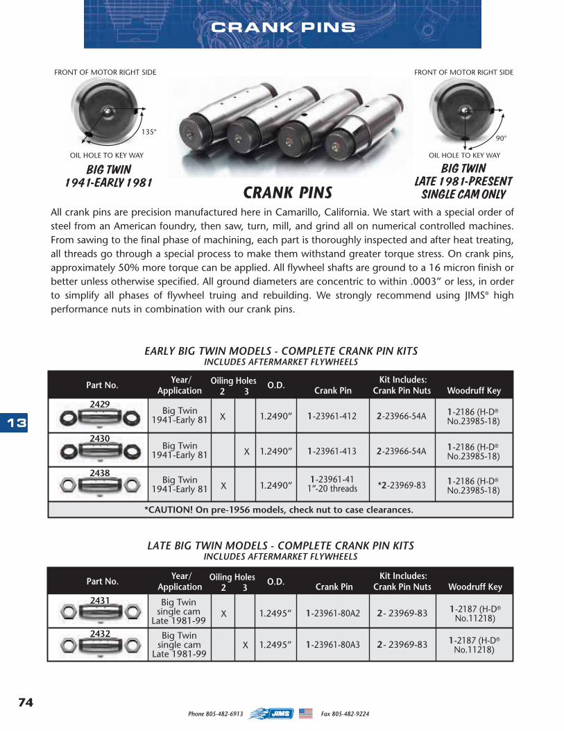
Phone 805-482-6913 Fax 805-482-922474
1323961-4123961-4123961-4123962-4023961-4123961-4123961-8023961-8023974-8723975-87
CRANK PINS
All crank pins are precision manufactured here in Camarillo, California. We start with a special order ofsteel from an American foundry, then saw, turn, mill, and grind all on numerical controlled machines.From sawing to the final phase of machining, each part is thoroughly inspected and after heat treating,all threads go through a special process to make them withstand greater torque stress. On crank pins,approximately 50% more torque can be applied. All flywheel shafts are ground to a 16 micron finish orbetter unless otherwise specified. All ground diameters are concentric to within .0003” or less, in orderto simplify all phases of flywheel truing and rebuilding. We strongly recommend using JIMS® highperformance nuts in combination with our crank pins.
CRANK PINSBIG TWIN
1941-EARLY 1981BIG TWIN
LATE 1981-PRESENTSINGLE CAM ONLY
24292430243824312432
1 -23961-412Big Twin1941-Early 81 X 1.2490” 1 -2186 (H-D®
No.23985-18)2 -23966-54A
2430Big Twin
1941-Early 81 X 1.2490” 1 -23961-413 1 -2186 (H-D®
No.23985-18)2 -23966-54A
Big Twin1941-Early 81 X 1.2490”
1 -23961-41 1 -2186 (H-D®
No.23985-18)1”-20 threads
2429
2438
1 -23961-80A2Big Twin
single camLate 1981-99
X 1.2495” 1 -2187 (H-D®
No.11218)2 - 23969-83
2432 Big Twinsingle cam
Late 1981-99X 1.2495” 1 -23961-80A3 1 -2187 (H-D®
No.11218)2 - 23969-83
2431
*2 -23969-83
O.D. Kit Includes:
Kit Includes:
2 3Oiling HolesPart No. Year/
Application Crank Pin Crank Pin Nuts Woodruff Key
2 3Application Crank Pin Crank Pin Nuts Woodruff KeyPart No. Year/
EARLY BIG TWIN MODELS - COMPLETE CRANK PIN KITSINCLUDES AFTERMARKET FLYWHEELS
LATE BIG TWIN MODELS - COMPLETE CRANK PIN KITSINCLUDES AFTERMARKET FLYWHEELS
*CAUTION! On pre-1956 models, check nut to case clearances.
O.D.Oiling Holes
MASTER 2013 CATALOG_JMS 2.qxp:Layout 1 8/2/12 8:27 PM Page 74
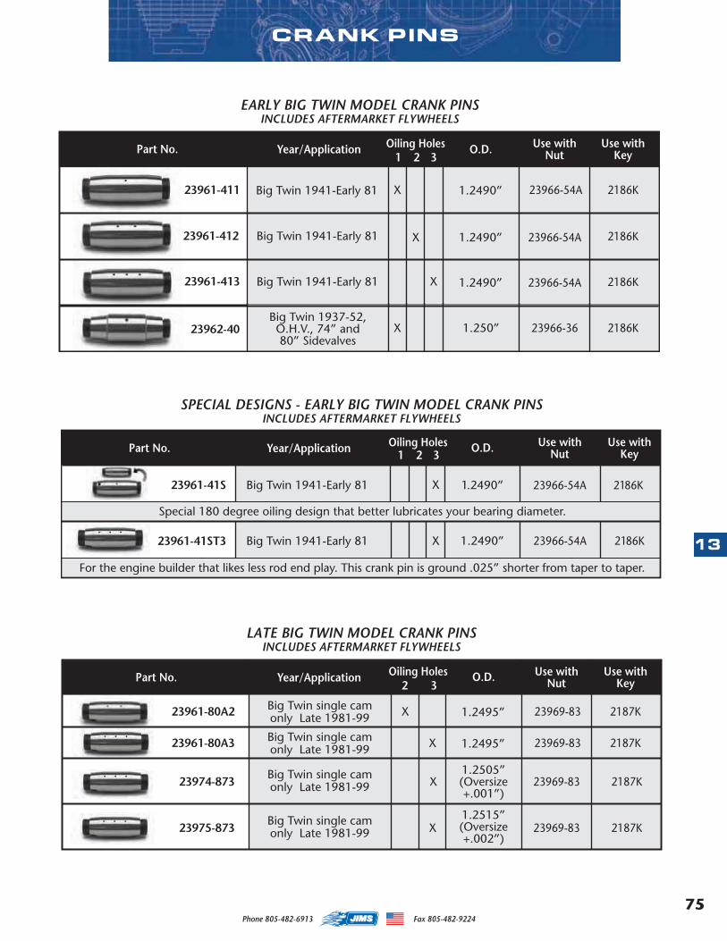
75
13
Phone 805-482-6913 Fax 805-482-9224
Use withNut
Use withKeyO.D.Oiling HolesYear/Application
23961-41S 23966-54A 2186KBig Twin 1941-Early 81
23961-41ST3 23966-54AX 1.2490”
Part No.
1.2490”
SPECIAL DESIGNS - EARLY BIG TWIN MODEL CRANK PINSINCLUDES AFTERMARKET FLYWHEELS
2186K
Special 180 degree oiling design that better lubricates your bearing diameter.
For the engine builder that likes less rod end play. This crank pin is ground .025” shorter from taper to taper.
Big Twin 1941-Early 81
1 2 3
X
CRANK PINS
23961-411 23966-54A 2186KBig Twin 1941-Early 81 X
23961-412 23966-54A
2186K
Big Twin 1941-Early 81 X 1.2490”
23966-54ABig Twin 1941-Early 81 X 1.2490”23961-413
1.2490”
2186K
Use withNut
Use withKeyYear/Application
1 2 3Part No.
EARLY BIG TWIN MODEL CRANK PINSINCLUDES AFTERMARKET FLYWHEELS
O.D.Oiling Holes
23966-36Big Twin 1937-52,O.H.V., 74” and80” Sidevalves
X23962-40 1.250” 2186K
23961-41123961-41223961-41323962-4023961-41S23961-41ST323961-80A223961-80A323974-87323975-873
MASTER 2013 CATALOG_JMS 2.qxp:Layout 1 8/2/12 8:27 PM Page 75
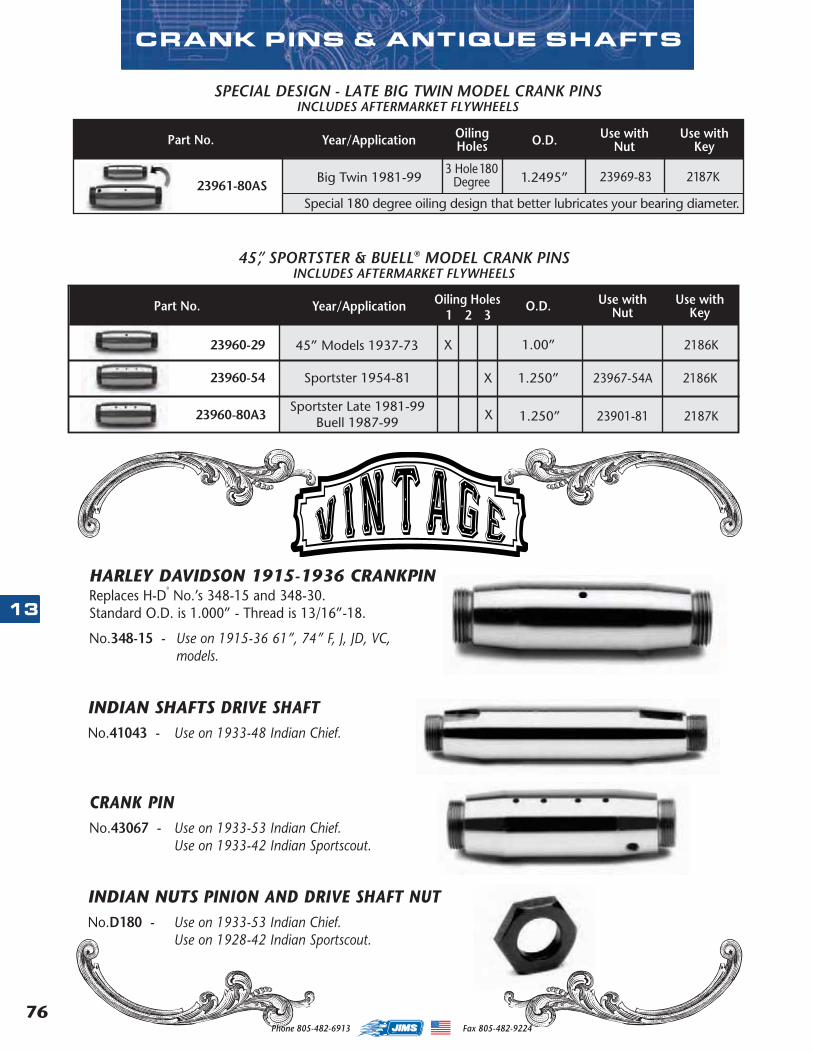
Phone 805-482-6913 Fax 805-482-922476
13
23966-3623966-5423969-8323967-5423901-8124017-8024023-3624003-3024003-5524023-3624016-8024022-9024023-54
Use withNut
Use withKeyO.D.Oiling
HolesYear/Application
23961-80AS23969-83 2187KBig Twin 1981-99
Part No.
1.2495”
SPECIAL DESIGN - LATE BIG TWIN MODEL CRANK PINSINCLUDES AFTERMARKET FLYWHEELS
3 Hole 180Degree
Special 180 degree oiling design that better lubricates your bearing diameter.
CRANK PINS & ANTIQUE SHAFTS
HARLEY DAVIDSON 1915-1936 CRANKPINReplaces H-D
®
No.’s 348-15 and 348-30.Standard O.D. is 1.000” - Thread is 13/16”-18.
No.348-15 - Use on 1915-36 61”, 74” F, J, JD, VC, VL, VE, VLD and VLHmodels.
INDIAN SHAFTS DRIVE SHAFTNo.41043 - Use on 1933-48 Indian Chief.
CRANK PINNo.43067 - Use on 1933-53 Indian Chief.
Use on 1933-42 Indian Sportscout.
INDIAN NUTS PINION AND DRIVE SHAFT NUTNo.D180 - Use on 1933-53 Indian Chief.
Use on 1928-42 Indian Sportscout.
23961-80AS23960-2923960-5423960-80A3
MASTER 2013 CATALOG_JMS 2.qxp:Layout 1 8/2/12 8:27 PM Page 76
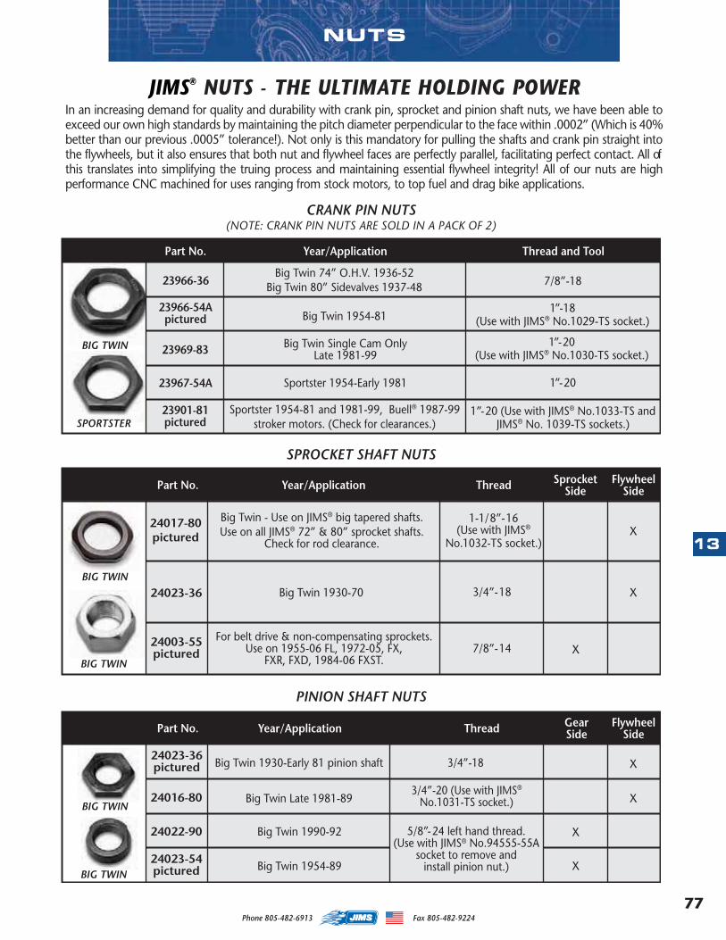
77
13
Phone 805-482-6913 Fax 805-482-9224
NUTS
In an increasing demand for quality and durability with crank pin, sprocket and pinion shaft nuts, we have been able toexceed our own high standards by maintaining the pitch diameter perpendicular to the face within .0002” (Which is 40%better than our previous .0005” tolerance!). Not only is this mandatory for pulling the shafts and crank pin straight intothe flywheels, but it also ensures that both nut and flywheel faces are perfectly parallel, facilitating perfect contact. All ofthis translates into simplifying the truing process and maintaining essential flywheel integrity! All of our nuts are highperformance CNC machined for uses ranging from stock motors, to top fuel and drag bike applications.
JIMS® NUTS - THE ULTIMATE HOLDING POWER
3/4”-18
Year/Application Thread and Tool
Year/Application FlywheelSideThread
BIG TWIN
SPORTSTER
SprocketSide
Year/Application FlywheelSideThread Gear
Side
BIG TWIN
BIG TWIN
BIG TWIN
BIG TWIN
23966-36Big Twin 74” O.H.V. 1936-52
Big Twin 80” Sidevalves 1937-48
23966-54Apictured
Part No.
23969-83
CRANK PIN NUTS
23967-54A
23901-81pictured
(NOTE: CRANK PIN NUTS ARE SOLD IN A PACK OF 2)
7/8”-18
Big Twin 1954-811”-18
(Use with JIMS® No.1029-TS socket.)
Sportster 1954-Early 1981
Big Twin Single Cam OnlyLate 1981-99
Sportster 1954-81 and 1981-99, Buell® 1987-99stroker motors. (Check for clearances.)
24017-80pictured
Big Twin - Use on JIMS® big tapered shafts.Use on all JIMS® 72” & 80” sprocket shafts.
Check for rod clearance.
24023-36
Part No.
1-1/8”-16(Use with JIMS®
No.1032-TS socket.)
3/4”-18
1”-20(Use with JIMS® No.1030-TS socket.)
1”-20
1”-20 (Use with JIMS® No.1033-TS andJIMS® No. 1039-TS sockets.)
SPROCKET SHAFT NUTS
X
Big Twin 1930-70 X
24003-55pictured
For belt drive & non-compensating sprockets.Use on 1955-06 FL, 1972-05, FX,
FXR, FXD, 1984-06 FXST.7/8”-14 X
24023-36pictured
24016-80
Part No.
3/4”-20 (Use with JIMS®
No.1031-TS socket.)
PINION SHAFT NUTS
X
Big Twin Late 1981-89 X
Big Twin 1990-92 X24022-90
24023-54pictured
5/8”-24 left hand thread.(Use with JIMS® No.94555-55A
socket to remove andinstall pinion nut.) X
Big Twin 1930-Early 81 pinion shaft
Big Twin 1954-89
23966-3623966-54A23969-8323967-54A23901-8124017-8024023-3624003-3024003-5524023-3624016-8024022-9024023-54
MASTER 2013 CATALOG_JMS 2.qxp:Layout 1 8/2/12 8:27 PM Page 77
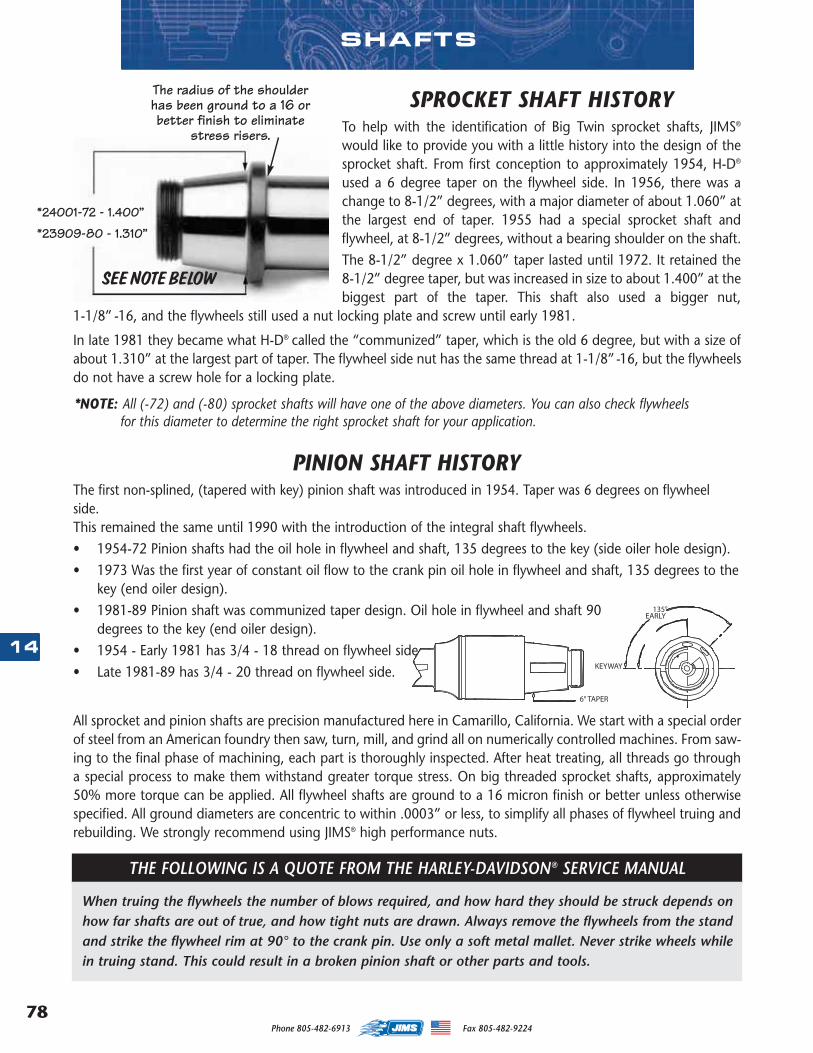
Phone 805-482-6913 Fax 805-482-922478
14
All sprocket and pinion shafts are precision manufactured here in Camarillo, California. We start with a special orderof steel from an American foundry then saw, turn, mill, and grind all on numerically controlled machines. From saw-ing to the final phase of machining, each part is thoroughly inspected. After heat treating, all threads go througha special process to make them withstand greater torque stress. On big threaded sprocket shafts, approximately50% more torque can be applied. All flywheel shafts are ground to a 16 micron finish or better unless otherwisespecified. All ground diameters are concentric to within .0003” or less, to simplify all phases of flywheel truing andrebuilding. We strongly recommend using JIMS® high performance nuts.
SPROCKET SHAFT HISTORYTo help with the identification of Big Twin sprocket shafts, JIMS®
would like to provide you with a little history into the design of thesprocket shaft. From first conception to approximately 1954, H-D®
used a 6 degree taper on the flywheel side. In 1956, there was achange to 8-1/2” degrees, with a major diameter of about 1.060” atthe largest end of taper. 1955 had a special sprocket shaft andflywheel, at 8-1/2” degrees, without a bearing shoulder on the shaft.The 8-1/2” degree x 1.060” taper lasted until 1972. It retained the8-1/2” degree taper, but was increased in size to about 1.400” at thebiggest part of the taper. This shaft also used a bigger nut,
1-1/8” -16, and the flywheels still used a nut locking plate and screw until early 1981.
In late 1981 they became what H-D® called the “communized” taper, which is the old 6 degree, but with a size ofabout 1.310” at the largest part of taper. The flywheel side nut has the same thread at 1-1/8” -16, but the flywheelsdo not have a screw hole for a locking plate.
SEE NOTE BELOW
PINION SHAFT HISTORYThe first non-splined, (tapered with key) pinion shaft was introduced in 1954. Taper was 6 degrees on flywheelside.This remained the same until 1990 with the introduction of the integral shaft flywheels.• 1954-72 Pinion shafts had the oil hole in flywheel and shaft, 135 degrees to the key (side oiler hole design).• 1973 Was the first year of constant oil flow to the crank pin oil hole in flywheel and shaft, 135 degrees to the
key (end oiler design).• 1981-89 Pinion shaft was communized taper design. Oil hole in flywheel and shaft 90
degrees to the key (end oiler design).• 1954 - Early 1981 has 3/4 - 18 thread on flywheel side.• Late 1981-89 has 3/4 - 20 thread on flywheel side.
6° TAPER
KEYWAY
135° EARLY
The radius of the shoulderhas been ground to a 16 orbetter finish to eliminate
stress risers.
*NOTE: All (-72) and (-80) sprocket shafts will have one of the above diameters. You can also check flywheelsfor this diameter to determine the right sprocket shaft for your application.
When truing the flywheels the number of blows required, and how hard they should be struck depends onhow far shafts are out of true, and how tight nuts are drawn. Always remove the flywheels from the standand strike the flywheel rim at 90° to the crank pin. Use only a soft metal mallet. Never strike wheels whilein truing stand. This could result in a broken pinion shaft or other parts and tools.
THE FOLLOWING IS A QUOTE FROM THE HARLEY-DAVIDSON® SERVICE MANUAL
SHAFTS
*24001-72 - 1.400”
*23909-80 - 1.310”
MASTER 2013 CATALOG_JMS 2.qxp:Layout 1 8/2/12 8:27 PM Page 78
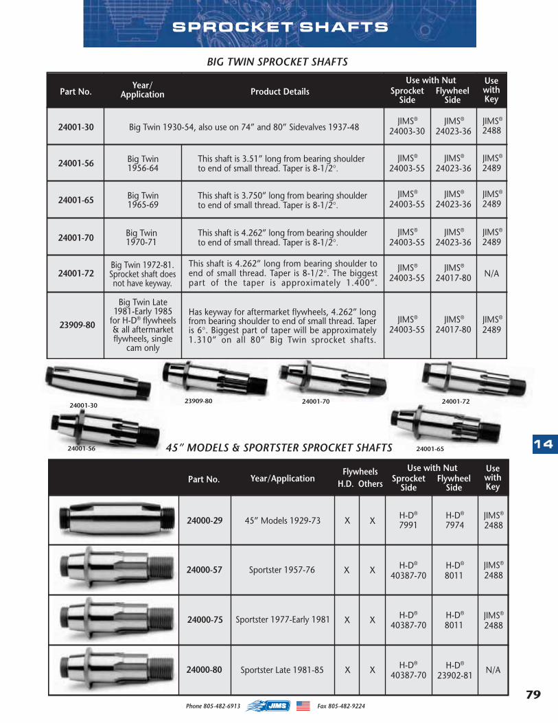
79
14
Phone 805-482-6913 Fax 805-482-9224
24000-2924000-5724000-7524000-80
SPROCKET SHAFTS
23909-80 24001-70 24001-7224001-30
24001-56 24001-65
24001-3024001-5624001-6524001-7024001-7223909-80
24000-29 799145” Models 1929-73 X
24000-572488
24000-75
45” MODELS & SPORTSTER SPROCKET SHAFTS
X 7974
Sportster 1957-76 X
XSportster 1977-Early 1981
2488
40387-70
40387-70 2488
24000-80 XSportster Late 1981-85 40387-70
8011
8011
23902-81
X
X
X
JIMS®H-D®H-D®
JIMS®H-D®H-D®
H-D® H-D® JIMS®
H-D®H-D®N/A
UsewithKey
SprocketSide
FlywheelsH.D. Others Flywheel
SidePart No.
Use with NutYear/Application
MASTER 2013 CATALOG_JMS 2.qxp:Layout 1 8/2/12 8:27 PM Page 79
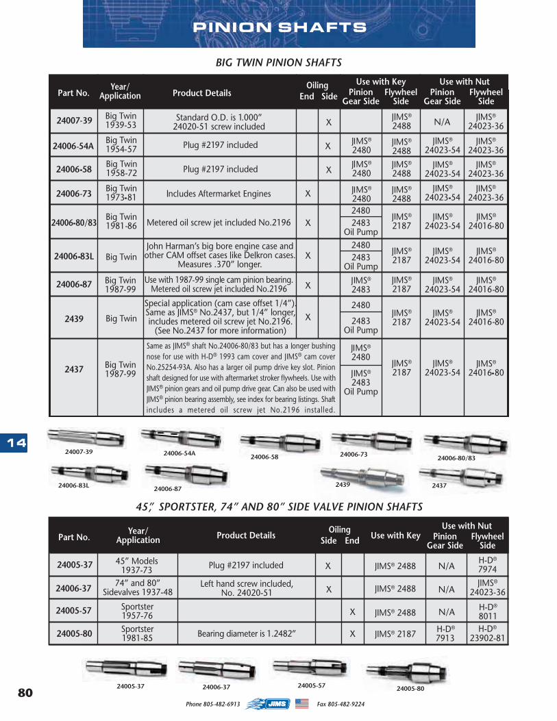
Phone 805-482-6913 Fax 805-482-922480
14
PINION SHAFTS
24005-37 24005-57 24005-8024006-37
24007-3924006-80/83
24006-54A
24006-87
24006-58 24006-73
243724006-83L 2439
24007-3924006-54A24006-5824006-7324006-80/8324006-83L24006-872439243724005-3724006-3724005-5724005-80
MASTER 2013 CATALOG_JMS 2.qxp:Layout 1 8/2/12 8:27 PM Page 80
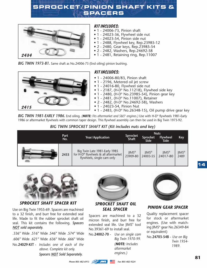
81
14
Phone 805-482-6913 Fax 805-482-9224
BIG TWIN 1981-EARLY 1986. End oiling. (NOTE: Fits aftermarket and S&S® engines.) Use with H-D® flywheels 1981-Early1986 or aftermarket flywheels with common taper design. This flywheel assembly can then be used in Big Twin 1973-92.
BIG TWIN 1973-81. Same shaft as No.24006-73 (End oiling) pinion bushing.
• 1 - 24006-80/83, Pinion shaft• 1 - 2196, Metered oil jet screw• 1 - 24016-80, Flywheel side nut• 1 - 2187, (H-D® No.11218), Flywheel side key• 1 - 2480, (H-D® No.23985-54), Pinion gear key• 1 - 2481, (H-D® No.11007), Retainer• 2 - 2482, (H-D® No.24692-58), Washers• 1 - 24023-54, Pinion Nut• 1 - 2483, (H-D® No.26348-15), Oil pump drive gear key
KIT INCLUDES:
2415
2434
KIT INCLUDES:• 1 - 24006-73, Pinion shaft• 1 - 24023-36, Flywheel side nut• 1 - 24023-54, Pinion side nut• 1 - 2488, Flywheel key, Rep.23985-12• 2 - 2480, Gear keys, Rep.23985-54• 2 - 2482, Washers, Rep.24692-58• 1 - 2481, Retaining ring, Rep.11007
SPROCKET/PINION SHAFT KITS &SPACERS
SPROCKET SHAFT SPACER KITUse on Big Twin 1955-69. Spacers are machinedto a 32 finish, and burr free for extended seallife. Made to fit the rubber sprocket shaft oilseal. This kit contains the following. SpacersNOT sold separately.
.336” Wide .516” Wide .546” Wide .574” Wide
.606” Wide .621” Wide .636” Wide .666” WideNo.24029-KIT - Includes one of each of the
above. Complete kit only.Spacers NOT Sold Separately.
SPROCKET SHAFT OILSEAL SPACER
Spacers are machined to a 32micron finish, and burr free forextended seal life. Use JIMS® toolNo.39361-69 to install seal.No.24002-70 - Use on single cam
Big Twin 1970-99. (NOTE: Includesaftermarketengines.)
PINION GEAR SPACERQuality replacement spacerfor stock or aftermarketengines. (Use with match-ing JIMS® gear No.26349-84or equivalent)No.24703-54B - Use on Big
Twin 1954-1989.
2433
MASTER 2013 CATALOG_JMS 2.qxp:Layout 1 8/2/12 8:27 PM Page 81
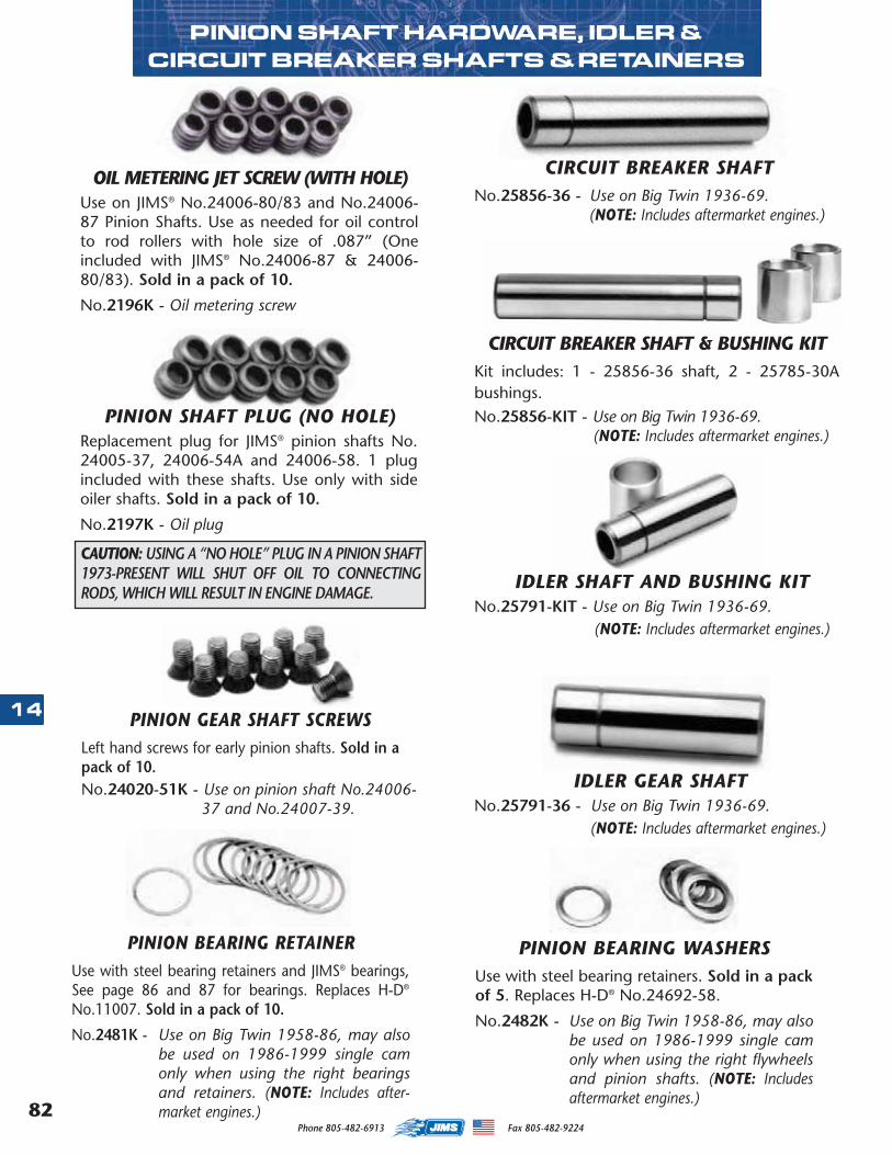
Phone 805-482-6913 Fax 805-482-922482
14 PINION GEAR SHAFT SCREWSLeft hand screws for early pinion shafts. Sold in apack of 10.No.24020-51K - Use on pinion shaft No.24006-
37 and No.24007-39.
OIL METERING JET SCREW (WITH HOLE)Use on JIMS® No.24006-80/83 and No.24006-87 Pinion Shafts. Use as needed for oil controlto rod rollers with hole size of .087” (Oneincluded with JIMS® No.24006-87 & 24006-80/83). Sold in a pack of 10.
No.2196K - Oil metering screw
PINION BEARING RETAINERUse with steel bearing retainers and JIMS® bearings,See page 86 and 87 for bearings. Replaces H-D®
No.11007. Sold in a pack of 10.
No.2481K - Use on Big Twin 1958-86, may alsobe used on 1986-1999 single camonly when using the right bearingsand retainers. (NOTE: Includes after-market engines.)
PINION SHAFT PLUG (NO HOLE)Replacement plug for JIMS® pinion shafts No.24005-37, 24006-54A and 24006-58. 1 plugincluded with these shafts. Use only with sideoiler shafts. Sold in a pack of 10.
No.2197K - Oil plug
CAUTION: USING A “NO HOLE” PLUG IN A PINION SHAFT1973-PRESENT WILL SHUT OFF OIL TO CONNECTINGRODS, WHICH WILL RESULT IN ENGINE DAMAGE.
PINION BEARING WASHERSUse with steel bearing retainers. Sold in a packof 5. Replaces H-D® No.24692-58.
No.2482K - Use on Big Twin 1958-86, may alsobe used on 1986-1999 single camonly when using the right flywheelsand pinion shafts. (NOTE: Includesaftermarket engines.)
PINION SHAFT HARDWARE, IDLER & CIRCUIT BREAKER SHAFTS & RETAINERS
IDLER GEAR SHAFTNo.25791-36 - Use on Big Twin 1936-69.
(NOTE: Includes aftermarket engines.)
IDLER SHAFT AND BUSHING KITNo.25791-KIT - Use on Big Twin 1936-69.
(NOTE: Includes aftermarket engines.)
CIRCUIT BREAKER SHAFTNo.25856-36 - Use on Big Twin 1936-69.
(NOTE: Includes aftermarket engines.)
CIRCUIT BREAKER SHAFT & BUSHING KITKit includes: 1 - 25856-36 shaft, 2 - 25785-30Abushings.No.25856-KIT - Use on Big Twin 1936-69.
(NOTE: Includes aftermarket engines.)
MASTER 2013 CATALOG_JMS 2.qxp:Layout 1 8/2/12 8:27 PM Page 82
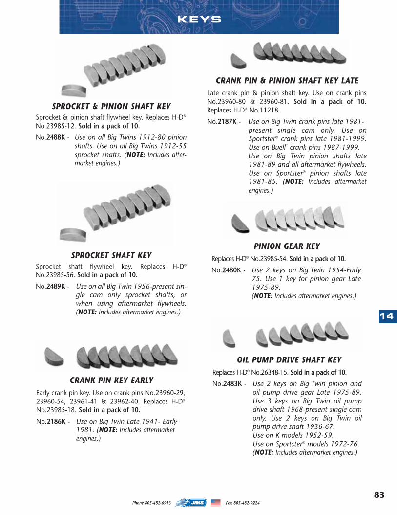
83
14
Phone 805-482-6913 Fax 805-482-9224
SPROCKET & PINION SHAFT KEYSprocket & pinion shaft flywheel key. Replaces H-D®
No.23985-12. Sold in a pack of 10.
No.2488K - Use on all Big Twins 1912-80 pinionshafts. Use on all Big Twins 1912-55sprocket shafts. (NOTE: Includes after-market engines.)
SPROCKET SHAFT KEYSprocket shaft flywheel key. Replaces H-D®
No.23985-56. Sold in a pack of 10.
No.2489K - Use on all Big Twin 1956-present sin-gle cam only sprocket shafts, orwhen using aftermarket flywheels.(NOTE: Includes aftermarket engines.)
CRANK PIN & PINION SHAFT KEY LATELate crank pin & pinion shaft key. Use on crank pinsNo.23960-80 & 23960-81. Sold in a pack of 10.Replaces H-D® No.11218.
No.2187K - Use on Big Twin crank pins late 1981-present single cam only. Use onSportster® crank pins late 1981-1999.Use on Buell
®
crank pins 1987-1999.Use on Big Twin pinion shafts late1981-89 and all aftermarket flywheels.Use on Sportster® pinion shafts late1981-85. (NOTE: Includes aftermarketengines.)
CRANK PIN KEY EARLYEarly crank pin key. Use on crank pins No.23960-29,23960-54, 23961-41 & 23962-40. Replaces H-D®
No.23985-18. Sold in a pack of 10.
No.2186K - Use on Big Twin Late 1941- Early 1981. (NOTE: Includes aftermarketengines.)
PINION GEAR KEYReplaces H-D® No.23985-54. Sold in a pack of 10.
No.2480K - Use 2 keys on Big Twin 1954-Early75. Use 1 key for pinion gear Late1975-89. (NOTE: Includes aftermarket engines.)
OIL PUMP DRIVE SHAFT KEYReplaces H-D® No.26348-15. Sold in a pack of 10.
No.2483K - Use 2 keys on Big Twin pinion andoil pump drive gear Late 1975-89.Use 3 keys on Big Twin oil pumpdrive shaft 1968-present single camonly. Use 2 keys on Big Twin oilpump drive shaft 1936-67.Use on K models 1952-59.Use on Sportster® models 1972-76.(NOTE: Includes aftermarket engines.)
KEYS
MASTER 2013 CATALOG_JMS 2.qxp:Layout 1 8/2/12 8:27 PM Page 83
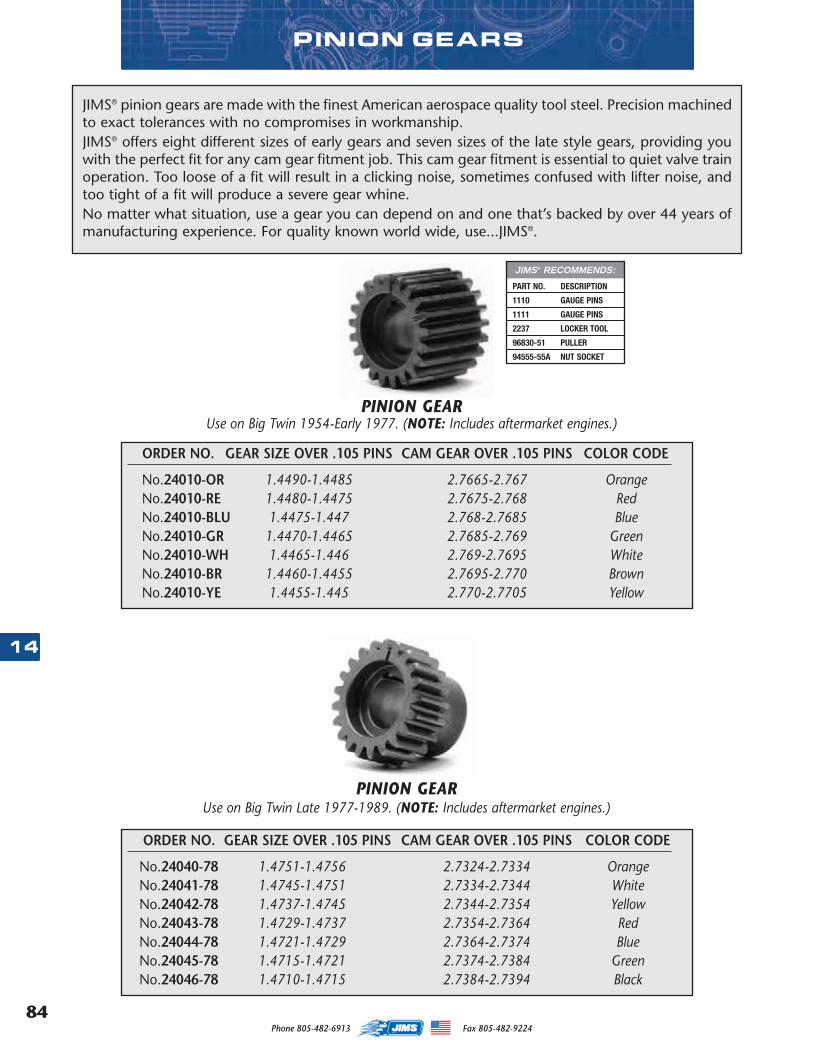
Phone 805-482-6913 Fax 805-482-922484
14
JIMS® pinion gears are made with the finest American aerospace quality tool steel. Precision machinedto exact tolerances with no compromises in workmanship.JIMS® offers eight different sizes of early gears and seven sizes of the late style gears, providing youwith the perfect fit for any cam gear fitment job. This cam gear fitment is essential to quiet valve trainoperation. Too loose of a fit will result in a clicking noise, sometimes confused with lifter noise, andtoo tight of a fit will produce a severe gear whine.No matter what situation, use a gear you can depend on and one that’s backed by over 44 years ofmanufacturing experience. For quality known world wide, use...JIMS®.
PINION GEARUse on Big Twin 1954-Early 1977. (NOTE: Includes aftermarket engines.)
PINION GEARUse on Big Twin Late 1977-1989. (NOTE: Includes aftermarket engines.)
ORDER NO. GEAR SIZE OVER .105 PINS CAM GEAR OVER .105 PINS COLOR CODE
No.24010-OR 1.4490-1.4485 2.7665-2.767 OrangeNo.24010-RE 1.4480-1.4475 2.7675-2.768 RedNo.24010-BLU 1.4475-1.447 2.768-2.7685 BlueNo.24010-GR 1.4470-1.4465 2.7685-2.769 GreenNo.24010-WH 1.4465-1.446 2.769-2.7695 WhiteNo.24010-BR 1.4460-1.4455 2.7695-2.770 BrownNo.24010-YE 1.4455-1.445 2.770-2.7705 Yellow
ORDER NO. GEAR SIZE OVER .105 PINS CAM GEAR OVER .105 PINS COLOR CODE
No.24040-78 1.4751-1.4756 2.7324-2.7334 OrangeNo.24041-78 1.4745-1.4751 2.7334-2.7344 WhiteNo.24042-78 1.4737-1.4745 2.7344-2.7354 YellowNo.24043-78 1.4729-1.4737 2.7354-2.7364 RedNo.24044-78 1.4721-1.4729 2.7364-2.7374 BlueNo.24045-78 1.4715-1.4721 2.7374-2.7384 GreenNo.24046-78 1.4710-1.4715 2.7384-2.7394 Black
PINION GEARS
PART NO. DESCRIPTION
1110 GAUGE PINS
1111 GAUGE PINS
2237 LOCKER TOOL
96830-51 PULLER
94555-55A NUT SOCKET
JIMS® RECOMMENDS:
MASTER 2013 CATALOG_JMS 2.qxp:Layout 1 8/2/12 8:27 PM Page 84
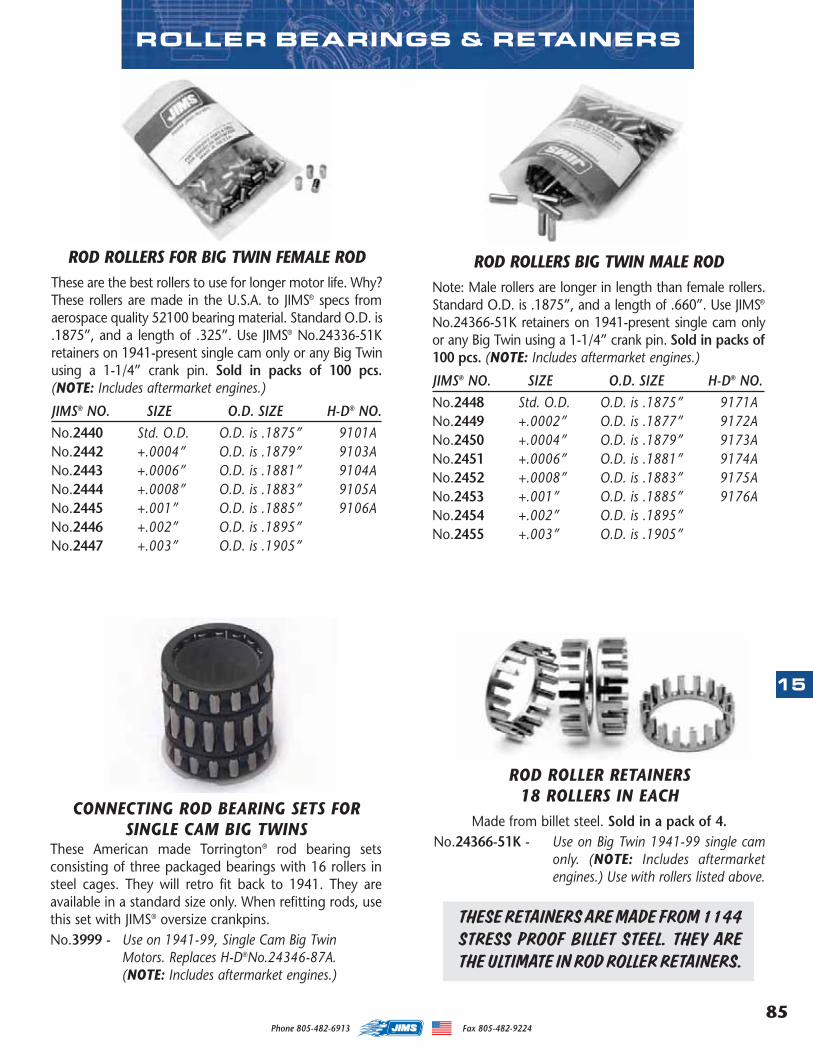
85
15
Phone 805-482-6913 Fax 805-482-9224
ROD ROLLERS FOR BIG TWIN FEMALE RODThese are the best rollers to use for longer motor life. Why?These rollers are made in the U.S.A. to JIMS® specs fromaerospace quality 52100 bearing material. Standard O.D. is.1875”, and a length of .325”. Use JIMS® No.24336-51Kretainers on 1941-present single cam only or any Big Twinusing a 1-1/4” crank pin. Sold in packs of 100 pcs.(NOTE: Includes aftermarket engines.)
JIMS® NO. SIZE O.D. SIZE H-D® NO.No.2440 Std. O.D. O.D. is .1875” 9101ANo.2442 +.0004” O.D. is .1879” 9103ANo.2443 +.0006” O.D. is .1881” 9104ANo.2444 +.0008” O.D. is .1883” 9105ANo.2445 +.001” O.D. is .1885” 9106ANo.2446 +.002” O.D. is .1895”No.2447 +.003” O.D. is .1905”
THESE RETAINERS ARE MADE FROM 1144STRESS PROOF BILLET STEEL. THEY ARETHE ULTIMATE IN ROD ROLLER RETAINERS.
ROD ROLLER RETAINERS18 ROLLERS IN EACH
Made from billet steel. Sold in a pack of 4.No.24366-51K - Use on Big Twin 1941-99 single cam
only. (NOTE: Includes aftermarketengines.) Use with rollers listed above.
CONNECTING ROD BEARING SETS FORSINGLE CAM BIG TWINS
These American made Torrington® rod bearing setsconsisting of three packaged bearings with 16 rollers insteel cages. They will retro fit back to 1941. They areavailable in a standard size only. When refitting rods, usethis set with JIMS® oversize crankpins.No.3999 - Use on 1941-99, Single Cam Big Twin
Motors. Replaces H-D®No.24346-87A. (NOTE: Includes aftermarket engines.)
ROD ROLLERS BIG TWIN MALE RODNote: Male rollers are longer in length than female rollers.Standard O.D. is .1875”, and a length of .660”. Use JIMS®
No.24366-51K retainers on 1941-present single cam onlyor any Big Twin using a 1-1/4” crank pin. Sold in packs of100 pcs. (NOTE: Includes aftermarket engines.)
JIMS® NO. SIZE O.D. SIZE H-D® NO.No.2448 Std. O.D. O.D. is .1875” 9171ANo.2449 +.0002” O.D. is .1877” 9172ANo.2450 +.0004” O.D. is .1879” 9173ANo.2451 +.0006” O.D. is .1881” 9174ANo.2452 +.0008” O.D. is .1883” 9175ANo.2453 +.001” O.D. is .1885” 9176ANo.2454 +.002” O.D. is .1895”No.2455 +.003” O.D. is .1905”
ROLLER BEARINGS & RETAINERS
MASTER 2013 CATALOG_JMS 2.qxp:Layout 1 8/2/12 8:27 PM Page 85
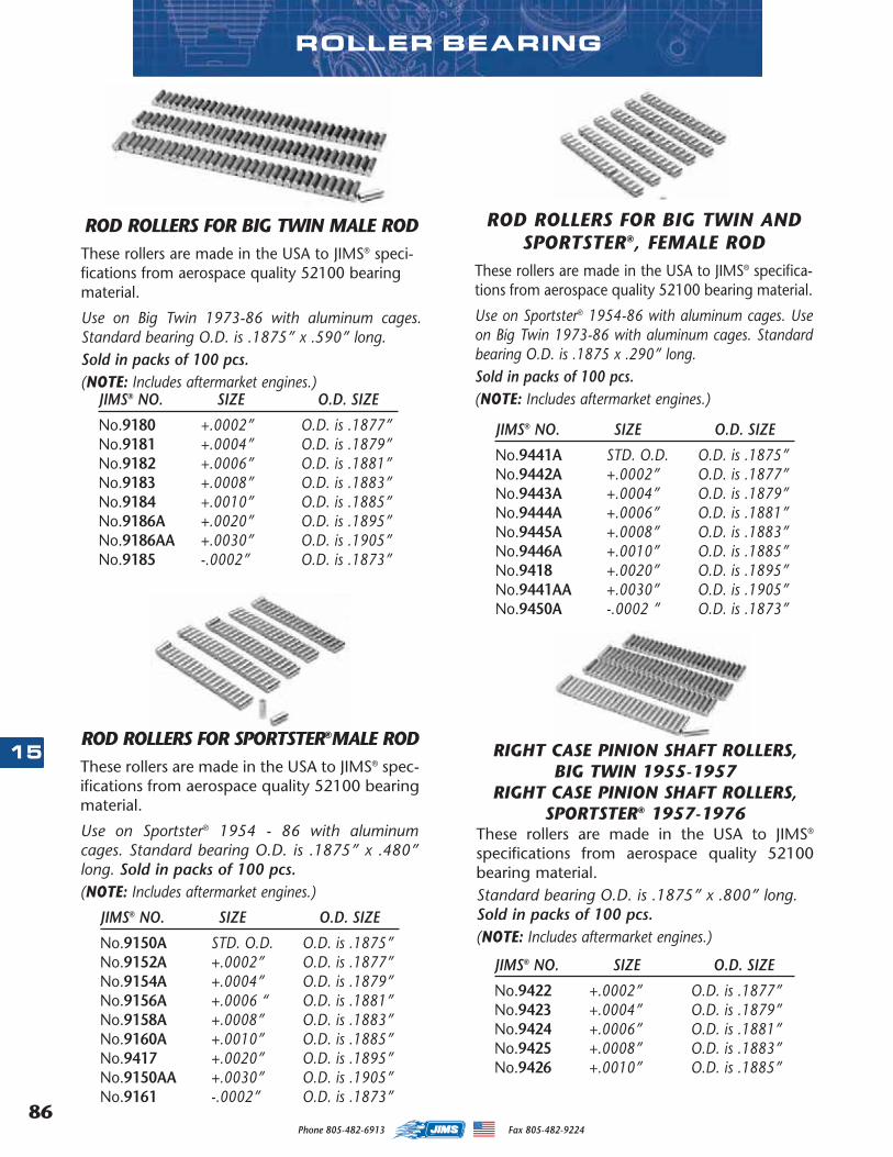
Phone 805-482-6913 Fax 805-482-922486
15
ROD ROLLERS FOR BIG TWIN MALE RODThese rollers are made in the USA to JIMS® speci-fications from aerospace quality 52100 bearingmaterial.
Use on Big Twin 1973-86 with aluminum cages.Standard bearing O.D. is .1875” x .590” long. Sold in packs of 100 pcs. (NOTE: Includes aftermarket engines.)
JIMS® NO. SIZE O.D. SIZE
No.9180 +.0002” O.D. is .1877”No.9181 +.0004” O.D. is .1879”No.9182 +.0006” O.D. is .1881”No.9183 +.0008” O.D. is .1883”No.9184 +.0010” O.D. is .1885”No.9186A +.0020” O.D. is .1895”No.9186AA +.0030” O.D. is .1905”No.9185 -.0002” O.D. is .1873”
ROD ROLLERS FOR SPORTSTER®MALE RODThese rollers are made in the USA to JIMS® spec-ifications from aerospace quality 52100 bearingmaterial.
Use on Sportster® 1954 - 86 with aluminumcages. Standard bearing O.D. is .1875” x .480”long. Sold in packs of 100 pcs. (NOTE: Includes aftermarket engines.)
JIMS® NO. SIZE O.D. SIZE
No.9150A STD. O.D. O.D. is .1875”No.9152A +.0002” O.D. is .1877”No.9154A +.0004” O.D. is .1879”No.9156A +.0006 “ O.D. is .1881”No.9158A +.0008” O.D. is .1883”No.9160A +.0010” O.D. is .1885”No.9417 +.0020” O.D. is .1895”No.9150AA +.0030” O.D. is .1905”No.9161 -.0002” O.D. is .1873”
ROD ROLLERS FOR BIG TWIN ANDSPORTSTER®, FEMALE ROD
These rollers are made in the USA to JIMS® specifica-tions from aerospace quality 52100 bearing material.
Use on Sportster® 1954-86 with aluminum cages. Useon Big Twin 1973-86 with aluminum cages. Standardbearing O.D. is .1875 x .290” long. Sold in packs of 100 pcs. (NOTE: Includes aftermarket engines.)
JIMS® NO. SIZE O.D. SIZE
No.9441A STD. O.D. O.D. is .1875”No.9442A +.0002” O.D. is .1877”No.9443A +.0004” O.D. is .1879”No.9444A +.0006” O.D. is .1881”No.9445A +.0008” O.D. is .1883”No.9446A +.0010” O.D. is .1885”No.9418 +.0020” O.D. is .1895”No.9441AA +.0030” O.D. is .1905”No.9450A -.0002 ” O.D. is .1873”
ROLLER BEARING
RIGHT CASE PINION SHAFT ROLLERS,BIG TWIN 1955-1957
RIGHT CASE PINION SHAFT ROLLERS,SPORTSTER® 1957-1976
These rollers are made in the USA to JIMS®
specifications from aerospace quality 52100bearing material. Standard bearing O.D. is .1875” x .800” long.Sold in packs of 100 pcs. (NOTE: Includes aftermarket engines.)
JIMS® NO. SIZE O.D. SIZE
No.9422 +.0002” O.D. is .1877”No.9423 +.0004” O.D. is .1879”No.9424 +.0006” O.D. is .1881”No.9425 +.0008” O.D. is .1883”No.9426 +.0010” O.D. is .1885”
MASTER 2013 CATALOG_JMS 2.qxp:Layout 1 8/2/12 8:27 PM Page 86
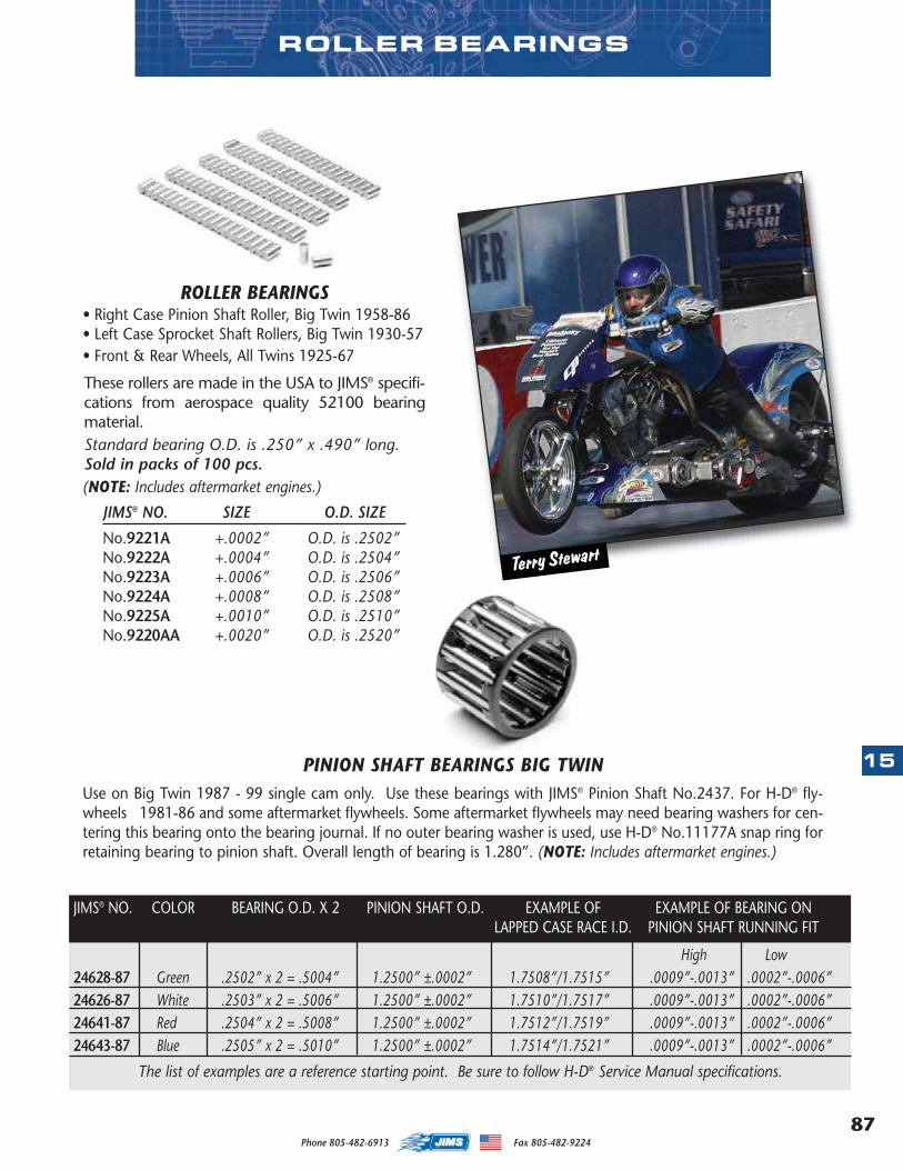
87
15
Phone 805-482-6913 Fax 805-482-9224
High Low24628-87 Green .2502” x 2 = .5004” 1.2500” ±.0002” 1.7508”/1.7515” .0009”-.0013” .0002”-.0006”24626-87 White .2503” x 2 = .5006” 1.2500” ±.0002” 1.7510”/1.7517” .0009”-.0013” .0002”-.0006”24641-87 Red .2504” x 2 = .5008” 1.2500” ±.0002” 1.7512”/1.7519” .0009”-.0013” .0002”-.0006”24643-87 Blue .2505” x 2 = .5010” 1.2500” ±.0002” 1.7514”/1.7521” .0009”-.0013” .0002”-.0006”
The list of examples are a reference starting point. Be sure to follow H-D® Service Manual specifications.
JIMS® NO. COLOR BEARING O.D. X 2 PINION SHAFT O.D. EXAMPLE OF EXAMPLE OF BEARING ONLAPPED CASE RACE I.D. PINION SHAFT RUNNING FIT
ROLLER BEARINGS
Terry Stewart
PINION SHAFT BEARINGS BIG TWINUse on Big Twin 1987 - 99 single cam only. Use these bearings with JIMS® Pinion Shaft No.2437. For H-D® fly-wheels 1981-86 and some aftermarket flywheels. Some aftermarket flywheels may need bearing washers for cen-tering this bearing onto the bearing journal. If no outer bearing washer is used, use H-D® No.11177A snap ring forretaining bearing to pinion shaft. Overall length of bearing is 1.280”. (NOTE: Includes aftermarket engines.)
ROLLER BEARINGS• Right Case Pinion Shaft Roller, Big Twin 1958-86• Left Case Sprocket Shaft Rollers, Big Twin 1930-57• Front & Rear Wheels, All Twins 1925-67
These rollers are made in the USA to JIMS® specifi-cations from aerospace quality 52100 bearingmaterial. Standard bearing O.D. is .250” x .490” long.Sold in packs of 100 pcs. (NOTE: Includes aftermarket engines.)
JIMS® NO. SIZE O.D. SIZE
No.9221A +.0002” O.D. is .2502”No.9222A +.0004” O.D. is .2504”No.9223A +.0006” O.D. is .2506”No.9224A +.0008” O.D. is .2508”No.9225A +.0010” O.D. is .2510”No.9220AA +.0020” O.D. is .2520”
MASTER 2013 CATALOG_JMS 2.qxp:Layout 1 8/2/12 8:27 PM Page 87
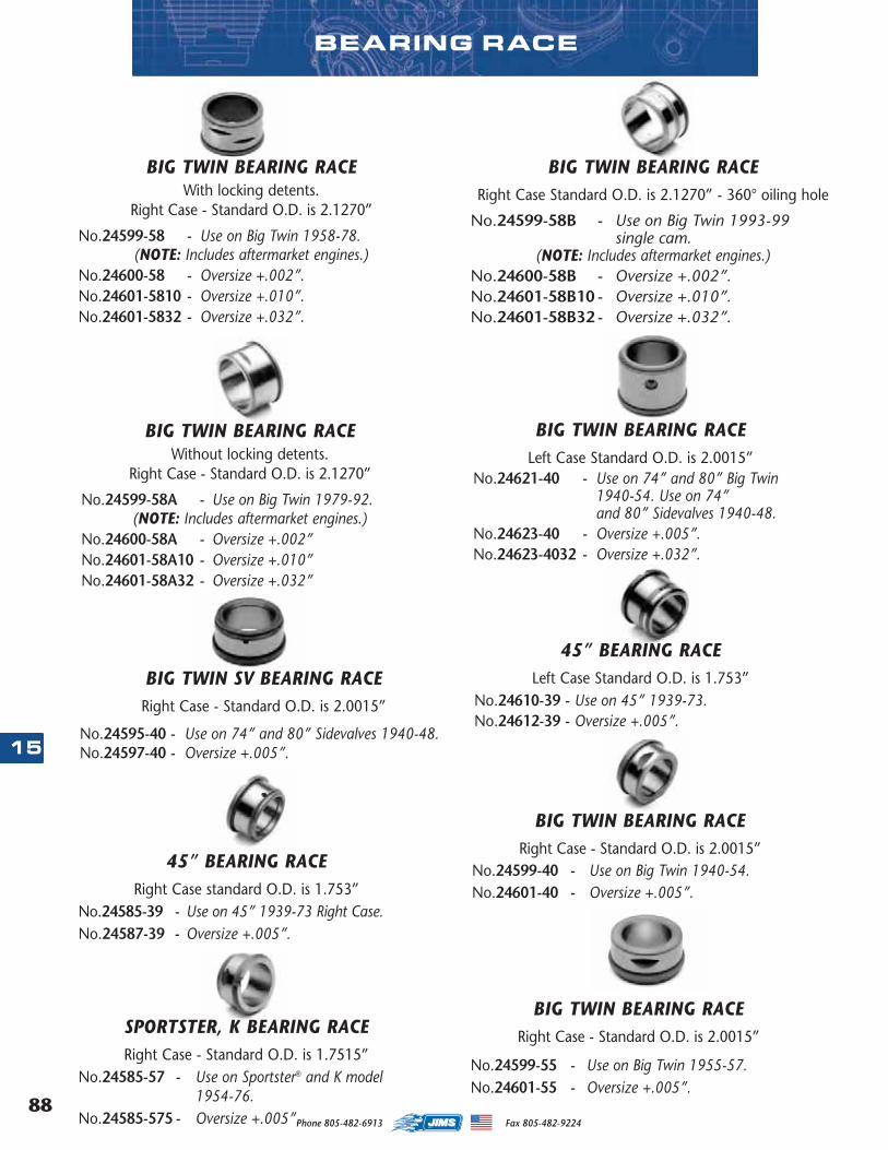
Phone 805-482-6913 Fax 805-482-922488
15
BEARING RACE
BIG TWIN BEARING RACEWith locking detents.
Right Case - Standard O.D. is 2.1270”
No.24599-58 - Use on Big Twin 1958-78. (NOTE: Includes aftermarket engines.)
No.24600-58 - Oversize +.002”.No.24601-5810 - Oversize +.010”.No.24601-5832 - Oversize +.032”.
BIG TWIN BEARING RACERight Case Standard O.D. is 2.1270” - 360° oiling hole
No.24599-58B - Use on Big Twin 1993-99 single cam.
(NOTE: Includes aftermarket engines.)No.24600-58B - Oversize +.002”.No.24601-58B10 - Oversize +.010”.No.24601-58B32 - Oversize +.032”.
BIG TWIN BEARING RACELeft Case Standard O.D. is 2.0015”
No.24621-40 - Use on 74” and 80” Big Twin 1940-54. Use on 74” and 80” Sidevalves 1940-48.
No.24623-40 - Oversize +.005”.No.24623-4032 - Oversize +.032”.
45” BEARING RACELeft Case Standard O.D. is 1.753”
No.24610-39 - Use on 45” 1939-73.No.24612-39 - Oversize +.005”.
BIG TWIN BEARING RACEWithout locking detents.
Right Case - Standard O.D. is 2.1270”
No.24599-58A - Use on Big Twin 1979-92. (NOTE: Includes aftermarket engines.)
No.24600-58A - Oversize +.002”No.24601-58A10 - Oversize +.010”No.24601-58A32 - Oversize +.032”
BIG TWIN SV BEARING RACERight Case - Standard O.D. is 2.0015”
No.24595-40 - Use on 74” and 80” Sidevalves 1940-48.No.24597-40 - Oversize +.005”.
BIG TWIN BEARING RACERight Case - Standard O.D. is 2.0015”
No.24599-40 - Use on Big Twin 1940-54.No.24601-40 - Oversize +.005”.
BIG TWIN BEARING RACERight Case - Standard O.D. is 2.0015”
No.24599-55 - Use on Big Twin 1955-57.No.24601-55 - Oversize +.005”.
45” BEARING RACERight Case standard O.D. is 1.753”
No.24585-39 - Use on 45” 1939-73 Right Case.No.24587-39 - Oversize +.005”.
SPORTSTER, K BEARING RACERight Case - Standard O.D. is 1.7515”
No.24585-57 - Use on Sportster® and K model 1954-76.
No.24585-575 - Oversize +.005”.
MASTER 2013 CATALOG_JMS 2.qxp:Layout 1 8/2/12 8:27 PM Page 88
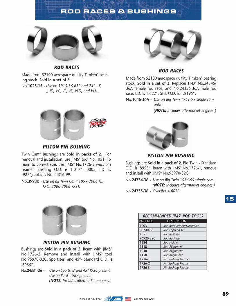
89
15
Phone 805-482-6913 Fax 805-482-9224
ROD RACESMade from 52100 aerospace quality Timken® bear-ing stock. Sold in a set of 3.No.1025-15 - Use on 1915-36 61” and 74” - F,
J, JD, VC, VL, VE, VLD, and VLH.
ROD RACESMade from 52100 aerospace quality Timken® bearingstock. Sold in a set of 3. Replaces H-D® No.24345-36A female rod race, and No.24356-36A male rodrace. I.D. is 1.622”, Std. O.D. is 1.8195”.No.1046-36A - Use on Big Twin 1941-99 single cam
only. (NOTE: Includes aftermarket engines.)
ROD RACES & BUSHINGS
RECOMMENDED JIMS® ROD TOOLS
1003 Rod Race remover/installer96740-36 Rod Lapping set1051 Rod Bushing96920-32C Rod Bushing1284 Rod Holder1148 Rod Alignment1010 Rod Alignment1158 Rod Alignment1726-1 Pin Bushing Reamer1726-2 Pin Bushing Reamer1726-3 Pin Bushing Reamer
PART NO. DESCRIPTION
PISTON PIN BUSHINGBushings are Sold in a pack of 2. Ream with JIMS®
No.1726-2. Remove and install with JIMS® toolNo.95970-32C. Sportster® and 45”- Standard O.D. is.8955”.No.24331-36 - Use on Sportster®and 45”1936-present.
Use on Buell®
1987-present. (NOTE: Includes aftermarket engines.)
PISTON PIN BUSHINGBushings are Sold in a pack of 2. Big Twin - StandardO.D. is .8955”. Ream with JIMS® No.1726-1, removeand install with JIMS® No.95970-32C.
No.24334-36 - Use on Big Twin 1936-99 single cam.(NOTE: Includes aftermarket engines.)
No.24335-36 - Oversize +.005”.
PISTON PIN BUSHINGTwin Cam® Bushings are Sold in packs of 2. Forremoval and installation, use JIMS® tool No.1051. Toream to correct size, use JIMS® No.1726-3 wrist pinreamer. Bushing O.D. is 1.017"+-.0005, I.D. is.927”,replaces No.24316-99.
No.3998K - Use on all Twin Cam® 1999-2006 FL, FXD, 2000-2006 FXST.
MASTER 2013 CATALOG_JMS 2.qxp:Layout 1 8/2/12 8:27 PM Page 89
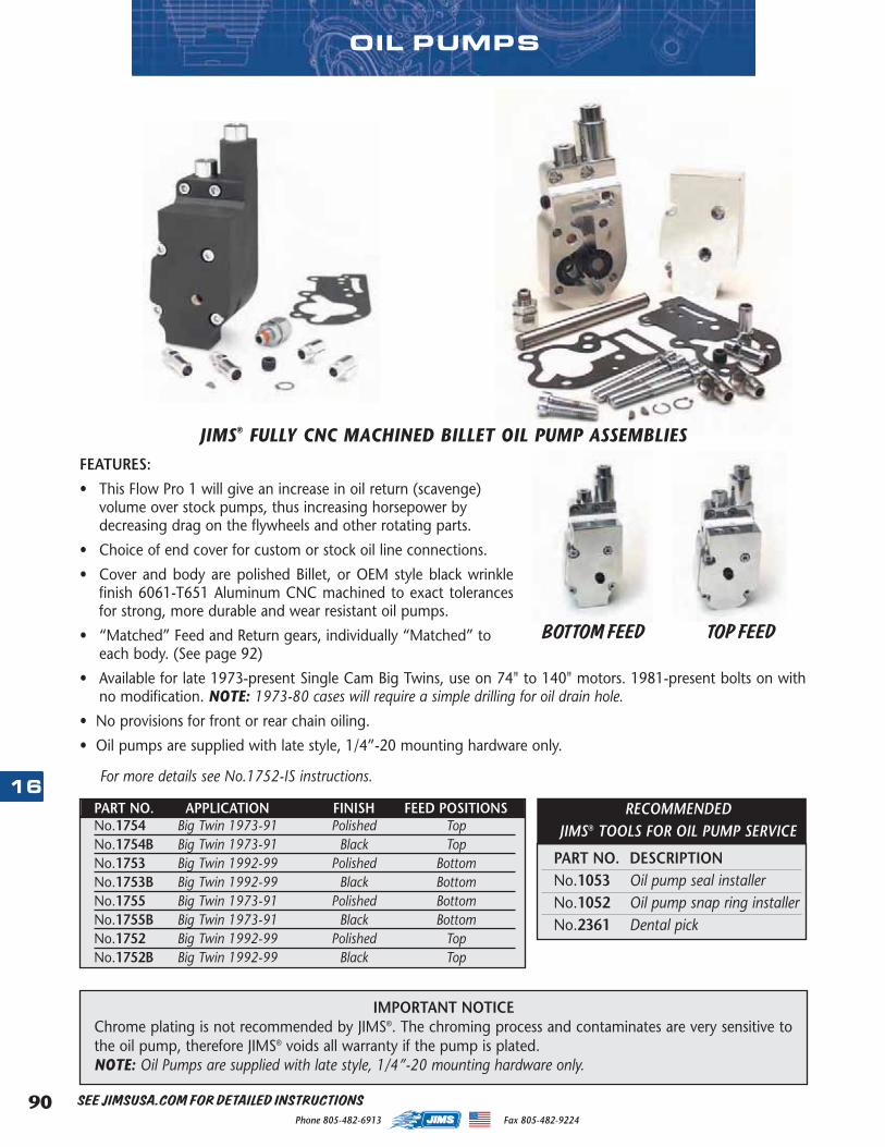
Phone 805-482-6913 Fax 805-482-922490
16
JIMS® FULLY CNC MACHINED BILLET OIL PUMP ASSEMBLIESFEATURES:
• This Flow Pro 1 will give an increase in oil return (scavenge)volume over stock pumps, thus increasing horsepower bydecreasing drag on the flywheels and other rotating parts.
• Choice of end cover for custom or stock oil line connections.
• Cover and body are polished Billet, or OEM style black wrinklefinish 6061-T651 Aluminum CNC machined to exact tolerancesfor strong, more durable and wear resistant oil pumps.
• “Matched” Feed and Return gears, individually “Matched” toeach body. (See page 92)
• Available for late 1973-present Single Cam Big Twins, use on 74" to 140" motors. 1981-present bolts on withno modification. NOTE: 1973-80 cases will require a simple drilling for oil drain hole.
• No provisions for front or rear chain oiling.
• Oil pumps are supplied with late style, 1/4”-20 mounting hardware only.
For more details see No.1752-IS instructions.
IMPORTANT NOTICEChrome plating is not recommended by JIMS®. The chroming process and contaminates are very sensitive tothe oil pump, therefore JIMS® voids all warranty if the pump is plated. NOTE: Oil Pumps are supplied with late style, 1/4”-20 mounting hardware only.
BOTTOM FEED TOP FEED
PART NO. APPLICATION FINISH FEED POSITIONSNo.1754 Big Twin 1973-91 Polished TopNo.1754B Big Twin 1973-91 Black TopNo.1753 Big Twin 1992-99 Polished BottomNo.1753B Big Twin 1992-99 Black BottomNo.1755 Big Twin 1973-91 Polished BottomNo.1755B Big Twin 1973-91 Black BottomNo.1752 Big Twin 1992-99 Polished TopNo.1752B Big Twin 1992-99 Black Top
OIL PUMPS
PART NO. DESCRIPTIONNo.1053 Oil pump seal installerNo.1052 Oil pump snap ring installerNo.2361 Dental pick
RECOMMENDED JIMS® TOOLS FOR OIL PUMP SERVICE
SEE JIMSUSA.COM FOR DETAILED INSTRUCTIONS
MASTER 2013 CATALOG_JMS 2.qxp:Layout 1 8/2/12 8:27 PM Page 90
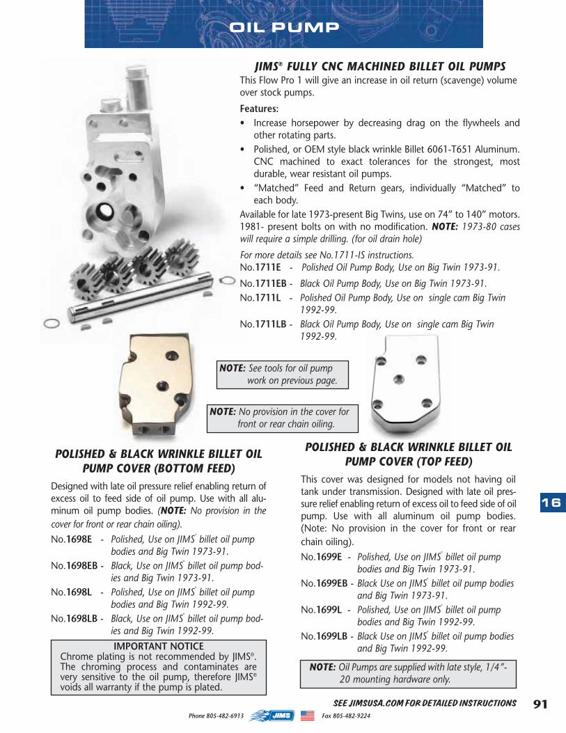
91
16
Phone 805-482-6913 Fax 805-482-9224
OIL PUMP
POLISHED & BLACK WRINKLE BILLET OILPUMP COVER (TOP FEED)
This cover was designed for models not having oiltank under transmission. Designed with late oil pres-sure relief enabling return of excess oil to feed side of oilpump. Use with all aluminum oil pump bodies.(Note: No provision in the cover for front or rearchain oiling).No.1699E - Polished, Use on JIMS
®
billet oil pumpbodies and Big Twin 1973-91.
No.1699EB - Black Use on JIMS®
billet oil pump bodiesand Big Twin 1973-91.
No.1699L - Polished, Use on JIMS®
billet oil pumpbodies and Big Twin 1992-99.
No.1699LB - Black Use on JIMS®
billet oil pump bodiesand Big Twin 1992-99.
JIMS® FULLY CNC MACHINED BILLET OIL PUMPSThis Flow Pro 1 will give an increase in oil return (scavenge) volumeover stock pumps.
Features:• Increase horsepower by decreasing drag on the flywheels and
other rotating parts.• Polished, or OEM style black wrinkle Billet 6061-T651 Aluminum.
CNC machined to exact tolerances for the strongest, mostdurable, wear resistant oil pumps.
• “Matched” Feed and Return gears, individually “Matched” toeach body.
Available for late 1973-present Big Twins, use on 74” to 140” motors.1981- present bolts on with no modification. NOTE: 1973-80 caseswill require a simple drilling. (for oil drain hole)
For more details see No.1711-IS instructions. No.1711E - Polished Oil Pump Body, Use on Big Twin 1973-91.
No.1711EB - Black Oil Pump Body, Use on Big Twin 1973-91.No.1711L - Polished Oil Pump Body, Use on single cam Big Twin
1992-99.No.1711LB - Black Oil Pump Body, Use on single cam Big Twin
1992-99.
NOTE: No provision in the cover forfront or rear chain oiling.
POLISHED & BLACK WRINKLE BILLET OILPUMP COVER (BOTTOM FEED)
Designed with late oil pressure relief enabling return ofexcess oil to feed side of oil pump. Use with all alu-minum oil pump bodies. (NOTE: No provision in thecover for front or rear chain oiling).No.1698E - Polished, Use on JIMS
®
billet oil pumpbodies and Big Twin 1973-91.
No.1698EB - Black, Use on JIMS®
billet oil pump bod-ies and Big Twin 1973-91.
No.1698L - Polished, Use on JIMS®
billet oil pumpbodies and Big Twin 1992-99.
No.1698LB - Black, Use on JIMS®
billet oil pump bod-ies and Big Twin 1992-99.
IMPORTANT NOTICEChrome plating is not recommended by JIMS®.The chroming process and contaminates arevery sensitive to the oil pump, therefore JIMS®
voids all warranty if the pump is plated.
NOTE: Oil Pumps are supplied with late style, 1/4”-20 mounting hardware only.
NOTE: See tools for oil pumpwork on previous page.
SEE JIMSUSA.COM FOR DETAILED INSTRUCTIONS
MASTER 2013 CATALOG_JMS 2.qxp:Layout 1 8/2/12 8:27 PM Page 91
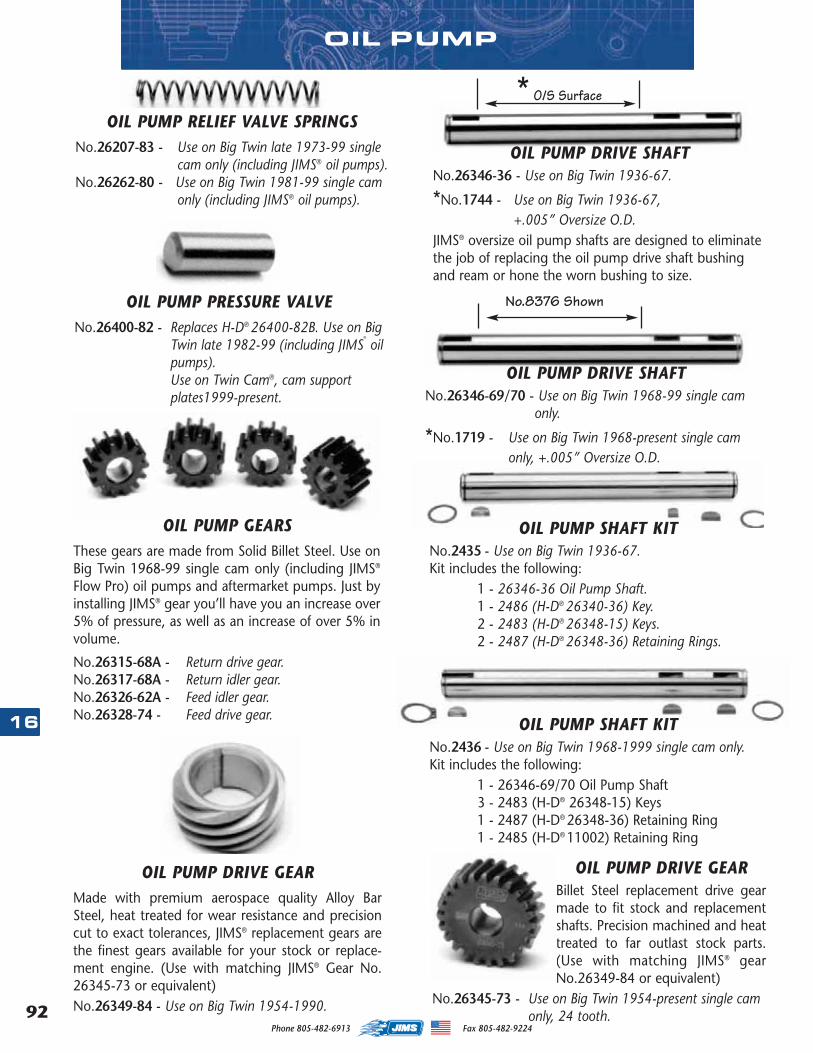
Phone 805-482-6913 Fax 805-482-922492
16
OIL PUMP
OIL PUMP RELIEF VALVE SPRINGSNo.26207-83 - Use on Big Twin late 1973-99 single
cam only (including JIMS® oil pumps).No.26262-80 - Use on Big Twin 1981-99 single cam
only (including JIMS® oil pumps).
OIL PUMP PRESSURE VALVENo.26400-82 - Replaces H-D® 26400-82B. Use on Big
Twin late 1982-99 (including JIMS®
oilpumps).Use on Twin Cam®, cam supportplates1999-present.
OIL PUMP DRIVE SHAFTNo.26346-36 - Use on Big Twin 1936-67.
*No.1744 - Use on Big Twin 1936-67,+.005” Oversize O.D.
JIMS® oversize oil pump shafts are designed to eliminatethe job of replacing the oil pump drive shaft bushingand ream or hone the worn bushing to size.
OIL PUMP DRIVE SHAFTNo.26346-69/70 - Use on Big Twin 1968-99 single cam
only.
*No.1719 - Use on Big Twin 1968-present single camonly, +.005” Oversize O.D.
OIL PUMP SHAFT KITNo.2435 - Use on Big Twin 1936-67.Kit includes the following:
1 - 26346-36 Oil Pump Shaft.1 - 2486 (H-D® 26340-36) Key.2 - 2483 (H-D® 26348-15) Keys.2 - 2487 (H-D® 26348-36) Retaining Rings.
OIL PUMP SHAFT KITNo.2436 - Use on Big Twin 1968-1999 single cam only.Kit includes the following:
1 - 26346-69/70 Oil Pump Shaft3 - 2483 (H-D® 26348-15) Keys1 - 2487 (H-D® 26348-36) Retaining Ring1 - 2485 (H-D® 11002) Retaining Ring
* O/S Surface
No.8376 Shown
OIL PUMP GEARSThese gears are made from Solid Billet Steel. Use onBig Twin 1968-99 single cam only (including JIMS®
Flow Pro) oil pumps and aftermarket pumps. Just byinstalling JIMS® gear you’ll have you an increase over5% of pressure, as well as an increase of over 5% involume.
No.26315-68A - Return drive gear.No.26317-68A - Return idler gear.No.26326-62A - Feed idler gear.No.26328-74 - Feed drive gear.
OIL PUMP DRIVE GEAR Made with premium aerospace quality Alloy BarSteel, heat treated for wear resistance and precisioncut to exact tolerances, JIMS® replacement gears arethe finest gears available for your stock or replace-ment engine. (Use with matching JIMS® Gear No.26345-73 or equivalent)No.26349-84 - Use on Big Twin 1954-1990.
OIL PUMP DRIVE GEARBillet Steel replacement drive gearmade to fit stock and replacementshafts. Precision machined and heattreated to far outlast stock parts.(Use with matching JIMS® gearNo.26349-84 or equivalent)
No.26345-73 - Use on Big Twin 1954-present single camonly, 24 tooth.
MASTER 2013 CATALOG_JMS 2.qxp:Layout 1 8/2/12 8:27 PM Page 92
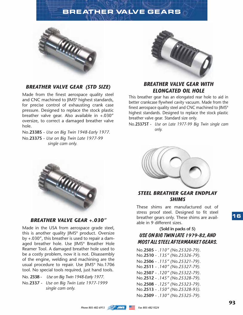
93
16
Phone 805-482-6913 Fax 805-482-9224
BREATHER VALVE GEAR +.030” Made in the USA from aerospace grade steel,this is another quality JIMS® product. Oversizeby +.030”, this breather is used to repair a dam-aged breather hole. Use JIMS® Breather HoleReamer Tool. A damaged breather hole used tobe a costly problem, now it is not. Disassemblyof the engine, welding and machining are theusual procedure to repair. Use JIMS® No.1706tool. No special tools required, just hand tools.
No. 2338 - Use on Big Twin 1948-Early 1977.No.2337 - Use on Big Twin Late 1977-1999
single cam only.
STEEL BREATHER GEAR ENDPLAYSHIMS
These shims are manufactured out ofstress proof steel. Designed to fit steelbreather gears only. These shims are avail-able in 9 different sizes.
(Sold in packs of 5)
USE ON BIG TWIN LATE 1979-82, ANDMOST ALL STEEL AFTERMARKET GEARS.No.2505 - .110” (No.25320-79).No.2510 - .135” (No.25326-79).No.2506 - .115” (No.25321-79).No.2511 - .140” (No.25327-79).No.2507 - .120” (No.25322-79).No.2512 - .145” (No.25328-79).No.2508 - .125” (No.25323-79).No.2513 - .150” (No.25328-93).No.2509 - .130” (No.25325-79).
BREATHER VALVE GEAR (STD SIZE)Made from the finest aerospace quality steeland CNC machined to JIMS® highest standards,for precise control of exhausting crank casepressure. Designed to replace the stock plasticbreather valve gear. Also available in +.030”oversize, to correct a damaged breather valvehole. No.2338S - Use on Big Twin 1948-Early 1977.No.2337S - Use on Big Twin Late 1977-99
single cam only.
BREATHER VALVE GEARS
BREATHER VALVE GEAR WITH ELONGATED OIL HOLE
This breather gear has an elongated rear hole to aid inbetter crankcase flywheel cavity vacuum. Made from thefinest aerospace quality steel and CNC machined to JIMS®
highest standards. Designed to replace the stock plasticbreather valve gear. Standard size only.No.2337ST - Use on Late 1977-99 Big Twin single cam
only.
MASTER 2013 CATALOG_JMS 2.qxp:Layout 1 8/2/12 8:27 PM Page 93
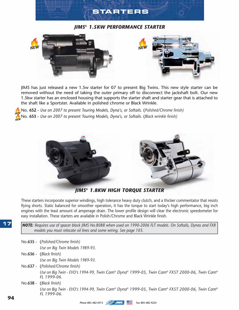
Phone 805-482-6913 Fax 805-482-922494
17
STARTERS
These starters incorporate superior windings, high tolerance heavy duty clutch, and a thicker commentator that resistsflying shorts. Static balanced for smoother operation, it has the torque to start today’s high performance, big inchengines with the least amount of amperage drain. The lower profile design will clear the electronic speedometer foreasy installation. These starters are available in Polish/Chrome and Black Wrinkle finish.
No.635 - (Polished/Chrome finish)Use on Big Twin Models 1989-93.
No.636 - (Black finish)Use on Big Twin Models 1989-93.
No.637 - (Polished/Chrome finish)Use on Big Twin - EVO’s 1994-99, Twin Cam® Dyna® 1999-05, Twin Cam® FXST 2000-06, Twin Cam®
FL 1999-06.No.638 - (Black finish)
Use on Big Twin - EVO’s 1994-99, Twin Cam® Dyna® 1999-05, Twin Cam® FXST 2000-06, Twin Cam®
FL 1999-06.
JIMS® 1.8KW HIGH TORQUE STARTER
NOTE: Requires use of spacer block JIMS No.8088 when used on 1990-2006 FLT models. On Softails, Dynas and FXRmodels you must relocate oil lines and some wiring. See page 103.
JIMS® 1.5KW PERFORMANCE STARTER
JIMS has just released a new 1.5w starter for 07 to present Big Twins. This new style starter can beremoved without the need of taking the outer primary off to disconnect the jackshaft bolt. Our new1.5kw starter has an enclosed housing that supports the starter shaft and starter gear that is attached tothe shaft like a Sportster. Available in polished chrome or Black Wrinkle.
No. 652 - Use on 2007 to present Touring Models, Dyna's, or Softails. (Polished/Chrome finish)No. 653 - Use on 2007 to present Touring Models, Dyna's, or Softails. (Black wrinkle finish)
NEW
NEW
NEW
NEW
MASTER 2013 CATALOG_JMS 2.qxp:Layout 1 8/2/12 8:27 PM Page 94
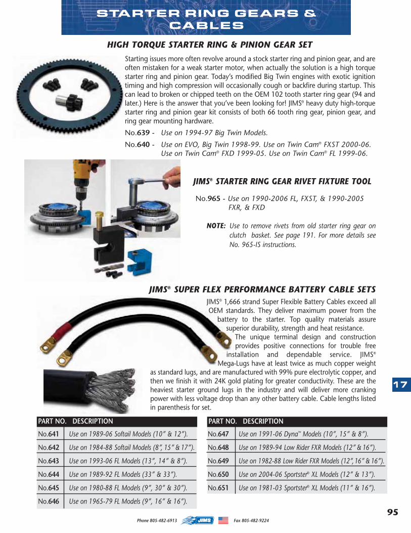
95
17
Phone 805-482-6913 Fax 805-482-9224
JIMS® STARTER RING GEAR RIVET FIXTURE TOOL
No.965 - Use on 1990-2006 FL, FXST, & 1990-2005FXR, & FXD
NOTE: Use to remove rivets from old starter ring gear onclutch basket. See page 191. For more details seeNo. 965-IS instructions.
JIMS® 1,666 strand Super Flexible Battery Cables exceed allOEM standards. They deliver maximum power from the
battery to the starter. Top quality materials assuresuperior durability, strength and heat resistance.
The unique terminal design and constructionprovides positive connections for trouble free
installation and dependable service. JIMS®
Mega-Lugs have at least twice as much copper weightas standard lugs, and are manufactured with 99% pure electrolytic copper, andthen we finish it with 24K gold plating for greater conductivity. These are theheaviest starter ground lugs in the industry and will deliver more crankingpower with less voltage drop than any other battery cable. Cable lengths listedin parenthesis for set.
No.641 Use on 1989-06 Softail Models (10” & 12”).
No.642 Use on 1984-88 Softail Models (8”, 15” & 17”).
No.643 Use on 1993-06 FL Models (13”, 14” & 8”).
No.644 Use on 1989-92 FL Models (33” & 33”).
No.645 Use on 1980-88 FL Models (9”, 30” & 30”).
No.646 Use on 1965-79 FL Models (9”, 16” & 16”).
No.647 Use on 1991-06 Dyna™ Models (10”, 15” & 8”).
No.648 Use on 1989-94 Low Rider FXR Models (12” & 16”).
No.649 Use on 1982-88 Low Rider FXR Models (12”,16” & 16”).
No.650 Use on 2004-06 Sportster® XL Models (12” & 13”).
No.651 Use on 1981-03 Sportster® XL Models (11” & 16”).
PART NO. DESCRIPTION PART NO. DESCRIPTION
STARTER RING GEARS &CABLES
Starting issues more often revolve around a stock starter ring and pinion gear, and areoften mistaken for a weak starter motor, when actually the solution is a high torquestarter ring and pinion gear. Today’s modified Big Twin engines with exotic ignitiontiming and high compression will occasionally cough or backfire during startup. Thiscan lead to broken or chipped teeth on the OEM 102 tooth starter ring gear (94 andlater.) Here is the answer that you’ve been looking for! JIMS® heavy duty high-torquestarter ring and pinion gear kit consists of both 66 tooth ring gear, pinion gear, andring gear mounting hardware.
No.639 - Use on 1994-97 Big Twin Models.
No.640 - Use on EVO, Big Twin 1998-99. Use on Twin Cam® FXST 2000-06.Use on Twin Cam® FXD 1999-05. Use on Twin Cam® FL 1999-06.
HIGH TORQUE STARTER RING & PINION GEAR SET
JIMS® SUPER FLEX PERFORMANCE BATTERY CABLE SETS
MASTER 2013 CATALOG_JMS 2.qxp:Layout 1 8/2/12 8:27 PM Page 95
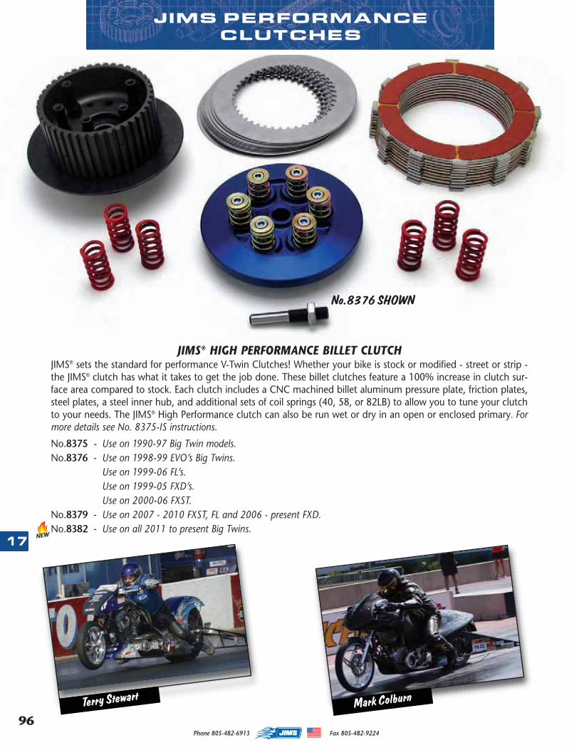
96
17
Phone 805-482-6913 Fax 805-482-9224
JIMS PERFORMANCECLUTCHES
JIMS® HIGH PERFORMANCE BILLET CLUTCHJIMS® sets the standard for performance V-Twin Clutches! Whether your bike is stock or modified - street or strip -the JIMS® clutch has what it takes to get the job done. These billet clutches feature a 100% increase in clutch sur-face area compared to stock. Each clutch includes a CNC machined billet aluminum pressure plate, friction plates,steel plates, a steel inner hub, and additional sets of coil springs (40, 58, or 82LB) to allow you to tune your clutchto your needs. The JIMS® High Performance clutch can also be run wet or dry in an open or enclosed primary. Formore details see No. 8375-IS instructions.
No.8375 - Use on 1990-97 Big Twin models.No.8376 - Use on 1998-99 EVO’s Big Twins.
Use on 1999-06 FL’s.Use on 1999-05 FXD’s.Use on 2000-06 FXST.
No.8379 - Use on 2007 - 2010 FXST, FL and 2006 - present FXD.No.8382 - Use on all 2011 to present Big Twins.
No.8376 SHOWN
NEW
Mark ColburnTerry Stewart
MASTER 2013 CATALOG_JMS 2.qxp:Layout 1 8/2/12 8:27 PM Page 96
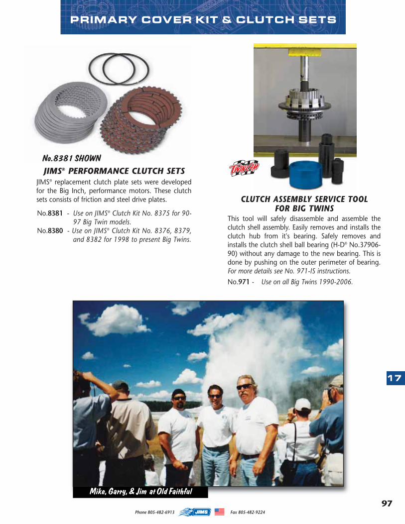
97
17
Phone 805-482-6913 Fax 805-482-9224
PRIMARY COVER KIT & CLUTCH SETS
JIMS® PERFORMANCE CLUTCH SETS JIMS® replacement clutch plate sets were developedfor the Big Inch, performance motors. These clutchsets consists of friction and steel drive plates.
No.8381 - Use on JIMS® Clutch Kit No. 8375 for 90-97 Big Twin models.
No.8380 - Use on JIMS® Clutch Kit No. 8376, 8379,and 8382 for 1998 to present Big Twins.
CLUTCH ASSEMBLY SERVICE TOOLFOR BIG TWINS
This tool will safely disassemble and assemble theclutch shell assembly. Easily removes and installs theclutch hub from it's bearing. Safely removes andinstalls the clutch shell ball bearing (H-D® No.37906-90) without any damage to the new bearing. This isdone by pushing on the outer perimeter of bearing.For more details see No. 971-IS instructions.
No.971 - Use on all Big Twins 1990-2006.
No.8381 SHOWN
Mike, Garry, & Jim at Old Faithful
MASTER 2013 CATALOG_JMS 2.qxp:Layout 1 8/14/12 8:21 AM Page 97
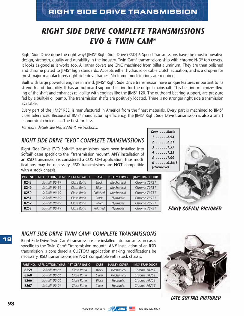
98
18
Phone 805-482-6913 Fax 805-482-9224
RIGHT SIDE DRIVE TRANSMISSION
Right Side Drive done the right way! JIMS® Right Side Drive (RSD) 6-Speed Transmissions have the most innovativedesign, strength, quality and durability in the industry. Twin Cam® transmissions ship with chrome H-D® top covers.It looks as good as it works too. All other covers are CNC machined from billet aluminum. They are then polishedand chrome plated to JIMS® high standards. Accepts either hydraulic or cable clutch actuation, and is a drop-in formost major manufacturers right side drive frames. No frame modifications are required.
Built with large powerful engines in mind, JIMS® Right Side Drive transmission have unique features important to itsstrength and durability. It has an outboard support bearing for the output mainshaft. This bearing minimizes flex-ing of the shaft and enhances reliability with engines like the JIMS® 120. The outboard bearing support, are pressurefed by a built-in oil pump. The transmission shafts are positively located. There is no stronger right side transmissionavailable.
Every part of the JIMS® RSD is manufactured in America from the finest materials. Every part is machined to JIMS®
close tolerances. Because of JIMS® manufacturing efficiency, the JIMS® Right Side Drive transmission is also a smarteconomical choice........The best for Less!
For more details see No. 8236-IS instructions.
Right Side Drive EVO Softail® transmissions have been installed intoSoftail® cases specific to the “transmission mount”. ANY installation ofan RSD transmission is considered a CUSTOM application, thus modi-fications may be necessary. RSD transmissions are NOT compatiblewith a stock chassis.
Right Side Drive Twin Cam® transmissions are installed into transmission casesspecific to the Twin Cam® “transmission mount”. ANY installation of an RSDtransmission is considered a CUSTOM application making modifications benecessary. RSD transmissions are NOT compatible with stock chassis.
PART NO. APPLICATION/ YEAR 1ST GEAR RATIO CASE PULLEY COVER JIMS® TRAP DOOR
8248 Softail® 90-99 Close Ratio Black Mechanical Chrome 7075T8249 Softail® 90-99 Close Ratio Silver Mechanical Chrome 7075T8250 Softail® 90-99 Close Ratio Polished Mechanical Chrome 7075T8251 Softail® 90-99 Close Ratio Black Hydraulic Chrome 7075T8252 Softail® 90-99 Close Ratio Silver Hydraulic Chrome 7075T8253 Softail® 90-99 Close Ratio Polished Hydraulic Chrome 7075T
PART NO. APPLICATION/ YEAR 1ST GEAR RATIO CASE PULLEY COVER JIMS® TRAP DOOR
8259 Softail® 00-06 Close Ratio Black Mechanical Chrome 7075T8260 Softail® 00-06 Close Ratio Silver Mechanical Chrome 7075T8266 Softail® 00-06 Close Ratio Black Hydraulic Chrome 7075T8267 Softail® 00-06 Close Ratio Silver Hydraulic Chrome 7075T
RIGHT SIDE DRIVE “EVO” COMPLETE TRANSMISSIONS
RIGHT SIDE DRIVE TWIN CAM® COMPLETE TRANSMISSIONS
RIGHT SIDE DRIVE COMPLETE TRANSMISSIONSEVO & TWIN CAM®
Gear . . . .Ratio1 . . . . . .2.942 . . . . . .2.213 . . . . . .1.574 . . . . . .1.235 . . . . . .1.006 . . . . . .0.86:1(Overdrive)
EARLY SOFTAIL PICTURED
LATE SOFTAIL PICTURED
MASTER 2013 CATALOG_JMS 2.qxp:Layout 1 8/2/12 8:27 PM Page 98

99
18
Phone 805-482-6913 Fax 805-482-9224
Built with large powerful engines in mind, JIMS® Right Side Drive transmission has unique features that are important to itsstrength and durability. It has an outboard support bearing for the output mainshaft. This bearing minimizes flexing of themainshaft and enhances reliability with engines like the JIMS® 120”, 131” & 135”. The bearing, including the outboard sup-port bearing, are pressure fed by a built-in oil pump. There is no stronger RSD transmission available.
JIMS® RSD 6 Speed Super kits are designed to install in any H-D® Softail® transmission case or aftermarket Softail® cases. Someminor modifications may be required to trans case depending on the manufacturer. Complete instructions for installationare provided with each kit. RSD super kits are supplied with a chrome aluminum trap door.
You’ll have a choice of a hydraulic actuated clutch pushrod system or a mechanical actuated pushrod. It is best if theseassembled RSD transmissions are installed in a RSD style frame offered by most frame manufacturers for ease of installationand fitment. For more details see No. 8236-IS instructions. RSD transmissions will not bolt into a stock style frame withoutextensive modification to the frame.
NOTE: Different parts options are listed below, depending on the year and type of trans case being used,either an EVO or Twin Cam®.
RSD SUPER KIT FITS:• No.8235 - 1990 - 2006 Softail® transmission cases, supplied with hydraulic actuated
clutch pushrod system. This hydraulic system will require a mastercylinder, hydraulic line and Dot 5 or equivalent(example of master cylinder kit H-D® No.45232-03A.)
• No.8236 - 1990 - 2006 Softail® transmission cases, supplied with mechanical actuated clutch pushrodsystem has a ball and ramp system that works with common O.E.M. type clutch cables.
OPTIONAL PRODUCT FOR INSTALLING A RSD IN A 1990-1999 EVO TRANSMISSION CASE:The following list of product will be required for installation, if not previously obtained or on the transmission case.
• No.7514 - Trans-case shifter shaft sleeve (replace existing sleeve or modify the longer early existing sleeve).
• No.1664 - Trans-case shifter shaft sleeve remover / installer tool, use to install JIMS®
No.7514 shifter shaft sleeve.
• No.33904-00 - Neutral switch with o-ring (this late switch must be installed when using aneutral light).
• No.8135 - Neutral switch wiring kit: (use on 1990-1997) use of this wiring kit will convert asingle pole wiring harness into a two pole wiring harness, instructions included.
• No.8136 - Neutral switch spacer kit: Required when using a OEM top cover (lid) from 1990 to1997 and switch No.33904-00.
OPTIONAL PRODUCTS FOR INSTALLING A RSD IN A 2000-2006TWIN CAM® TRANSMISSION CASE:The following list of product will be required for installation, if not previouslyobtained or on the transmission case.• No.33904-00 - Neutral switch with o-ring (this late switch must be installed when
using a neutral light).
• No.8135 - Neutral switch wiring kit: use of this wiring kit will convert a single pole wiringharness into a two pole wiring harness or for custom wiring application, instruc-tions included.
No.8246HYDRAULIC VERSION
No.8247MECHANICAL VERSION
RIGHT SIDE DRIVE TRANSMISSION
RIGHT SIDE DRIVE, 6-SPEED OVERDRIVE, SUPERKITS TWIN CAM® & EVO SOFTAILS
MASTER 2013 CATALOG_JMS 2.qxp:Layout 1 8/2/12 8:27 PM Page 99
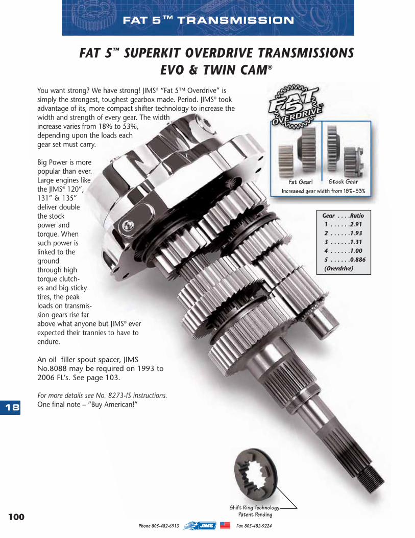
100
18
Phone 805-482-6913 Fax 805-482-9224
FAT 5™ TRANSMISSION
You want strong? We have strong! JIMS® “Fat 5™ Overdrive” issimply the strongest, toughest gearbox made. Period. JIMS® tookadvantage of its, more compact shifter technology to increase thewidth and strength of every gear. The widthincrease varies from 18% to 53%,depending upon the loads eachgear set must carry.
Big Power is morepopular than ever.Large engines likethe JIMS® 120”,131” & 135”deliver doublethe stockpower andtorque. Whensuch power islinked to thegroundthrough hightorque clutch-es and big stickytires, the peakloads on transmis-sion gears rise farabove what anyone but JIMS® everexpected their trannies to have toendure.
An oil filler spout spacer, JIMSNo.8088 may be required on 1993 to2006 FL’s. See page 103.
For more details see No. 8273-IS instructions.One final note – “Buy American!”
Shift Ring Technology
Increased gear width from 18%~53%Fat Gear! Stock Gear
FAT 5™ SUPERKIT OVERDRIVE TRANSMISSIONSEVO & TWIN CAM®
Gear . . . .Ratio1 . . . . . .2.912 . . . . . .1.933 . . . . . .1.314 . . . . . .1.005 . . . . . .0.886(Overdrive)
Patent Pending
MASTER 2013 CATALOG_JMS 2.qxp:Layout 1 8/2/12 8:27 PM Page 100
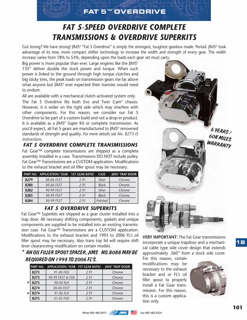
101
18
Phone 805-482-6913 Fax 805-482-9224
Got strong? We have strong! JIMS® “Fat 5 Overdrive” is simply the strongest, toughest gearbox made. Period. JIMS® tookadvantage of its new, more compact shifter technology to increase the width and strength of every gear. The widthincrease varies from 18% to 53%, depending upon the loads each gear set must carry.Big power is more popular than ever. Large engines like the JIMS®
135” deliver double the stock power and torque. When suchpower is linked to the ground through high torque clutches andbig sticky tires, the peak loads on transmission gears rise far abovewhat anyone but JIMS® ever expected their trannies would needto endure.All are available with a mechanical clutch activated system only.The Fat 5 Overdrive fits both Evo and Twin Cam® chassis.However, it is wider on the right side which may interfere withother components. For this reason, we consider our Fat 5Overdrive to be part of a custom build and not a drop-in product.It is available as a JIMS® Super Kit or complete transmission. Asyou’d expect, all Fat 5 gears are manufactured to JIMS® renownedstandards of strength and quality. For more details see No. 8273-ISinstructions.
Fat Gear™ complete transmissions are shipped as a completeassembly installed in a case. Transmissions DO NOT include pulley.Fat Gear™ Transmissions are a CUSTOM application. Modificationsto the exhaust bracket and oil filler spout may be necessary.
PART NO. APPLICATION/ YEAR 1ST GEAR RATIO CASE JIMS® TRAP DOOR
8279 00-06 FXST 2.91 Silver Chrome8280 00-06 FXST 2.91 Black Chrome8282 90-99 FXST 2.91 Silver Chrome8283 90-99 FXST 2.91 Black Chrome8284 90-99 FXST 2.91 Polished Chrome
PART NO. APPLICATION/ YEAR 1ST GEAR RATIO JIMS® TRAP DOOR
8273 91-00 FXD 2.91 Chrome8273 90-99 FXST & FXR 2.91 Chrome8273 90-00 FLH 2.91 Chrome8274 00-06 FXST 2.91 Chrome8274 01-06 FLH 2.91 Chrome8275 01-05 FXD 2.91 Chrome
FAT 5 OVERDRIVE COMPLETE TRANSMISSIONS
FAT 5 OVERDRIVE SUPERKITS
*
*
VERY IMPORTANT: The Fat Gear transmissionsincorporate a unique trapdoor and a mechani-cal cable type side cover design that extendsapproximately .560” from a stock side cover.For this reason, certainmodifications may benecessary to the exhaustbracket and or FL’s oilfiller spout to properlyinstall a Fat Gear trans-mission. For this reason,this is a custom applica-tion only.
+.560” Over Stock
FAT 5-SPEED OVERDRIVE COMPLETETRANSMISSIONS & OVERDRIVE SUPERKITS
Fat Gear™ Superkits are shipped as a gear cluster installed into atrap door. All necessary shifting components, gaskets and uniquecomponents are supplied to be installed into an existing transmis-sion case. Fat Gear™ Transmissions are a CUSTOM application.Modifications to the exhaust bracket and 1993 to 2006 FL’s oilfiller spout may be necessary. Also trans top lid will require shiftlever clearanceing modification on certain models.
* AN OIL FILLER SPOUT SPACER, JIMS NO.8088 MAY BEREQUIRED ON 1993 TO 2006 FL’S.
FAT 5 ™ OVERDRIVE
6 YEARS /60K MILESWARRANTY
MASTER 2013 CATALOG_JMS 2.qxp:Layout 1 8/2/12 8:27 PM Page 101
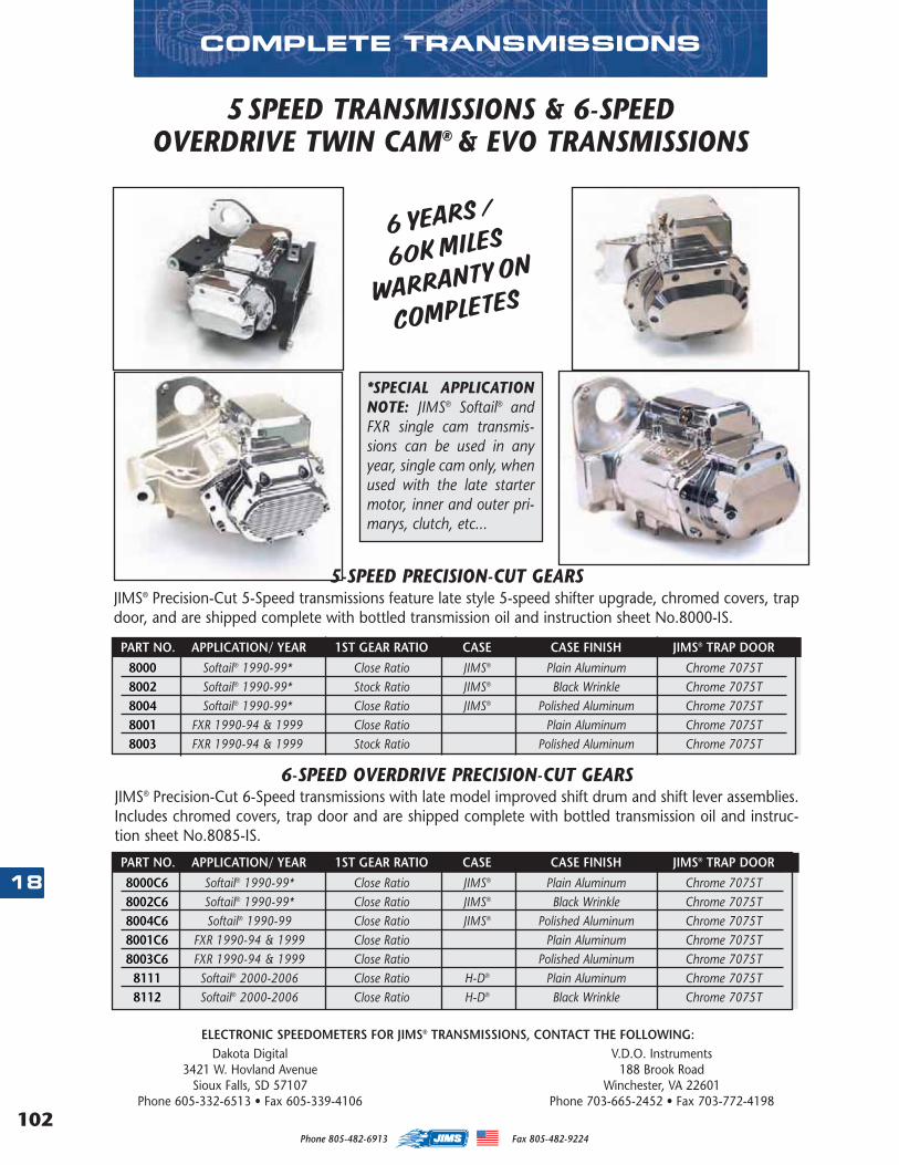
102
18
Phone 805-482-6913 Fax 805-482-9224
COMPLETE TRANSMISSIONS
ELECTRONIC SPEEDOMETERS FOR JIMS® TRANSMISSIONS, CONTACT THE FOLLOWING:Dakota Digital V.D.O. Instruments
3421 W. Hovland Avenue 188 Brook RoadSioux Falls, SD 57107 Winchester, VA 22601
Phone 605-332-6513 • Fax 605-339-4106 Phone 703-665-2452 • Fax 703-772-4198
PART NO. APPLICATION/ YEAR 1ST GEAR RATIO CASE CASE FINISH JIMS® TRAP DOOR
8000 Softail® 1990-99* Close Ratio JIMS® Plain Aluminum Chrome 7075T8002 Softail® 1990-99* Stock Ratio JIMS® Black Wrinkle Chrome 7075T8004 Softail® 1990-99* Close Ratio JIMS® Polished Aluminum Chrome 7075T8001 FXR 1990-94 & 1999 Close Ratio Plain Aluminum Chrome 7075T8003 FXR 1990-94 & 1999 Stock Ratio Polished Aluminum Chrome 7075T
5-SPEED PRECISION-CUT GEARSJIMS® Precision-Cut 5-Speed transmissions feature late style 5-speed shifter upgrade, chromed covers, trapdoor, and are shipped complete with bottled transmission oil and instruction sheet No.8000-IS.
5SPEED TRANSMISSIONS & 6-SPEED OVERDRIVE TWIN CAM® & EVO TRANSMISSIONS
6-SPEED OVERDRIVE PRECISION-CUT GEARSJIMS® Precision-Cut 6-Speed transmissions with late model improved shift drum and shift lever assemblies.Includes chromed covers, trap door and are shipped complete with bottled transmission oil and instruc-tion sheet No.8085-IS.
PART NO. APPLICATION/ YEAR 1ST GEAR RATIO CASE CASE FINISH JIMS® TRAP DOOR
8000C6 Softail® 1990-99* Close Ratio JIMS® Plain Aluminum Chrome 7075T8002C6 Softail® 1990-99* Close Ratio JIMS® Black Wrinkle Chrome 7075T8004C6 Softail® 1990-99 Close Ratio JIMS® Polished Aluminum Chrome 7075T8001C6 FXR 1990-94 & 1999 Close Ratio Plain Aluminum Chrome 7075T8003C6 FXR 1990-94 & 1999 Close Ratio Polished Aluminum Chrome 7075T
8111 Softail® 2000-2006 Close Ratio H-D® Plain Aluminum Chrome 7075T8112 Softail® 2000-2006 Close Ratio H-D® Black Wrinkle Chrome 7075T
*SPECIAL APPLICATIONNOTE: JIMS® Softail® andFXR single cam transmis-sions can be used in anyyear, single cam only, whenused with the late startermotor, inner and outer pri-marys, clutch, etc...
6 YEARS /
60K MILES
WARRANTY ON
COMPLETES
MASTER 2013 CATALOG_JMS 2.qxp:Layout 1 8/2/12 8:27 PM Page 102
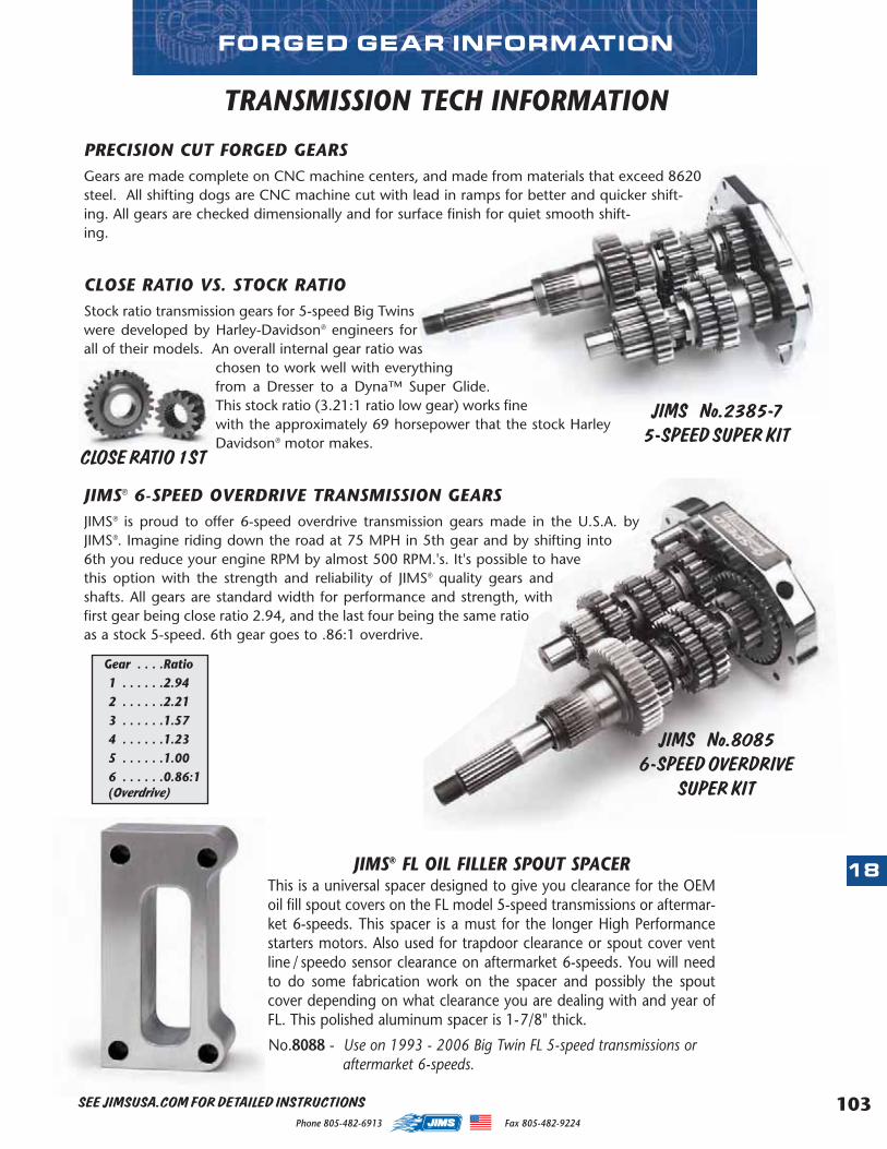
103
18
Phone 805-482-6913 Fax 805-482-9224
TRANSMISSION TECH INFORMATION
PRECISION CUT FORGED GEARSGears are made complete on CNC machine centers, and made from materials that exceed 8620steel. All shifting dogs are CNC machine cut with lead in ramps for better and quicker shift-ing. All gears are checked dimensionally and for surface finish for quiet smooth shift-ing.
CLOSE RATIO VS. STOCK RATIOStock ratio transmission gears for 5-speed Big Twinswere developed by Harley-Davidson® engineers forall of their models. An overall internal gear ratio was
chosen to work well with everythingfrom a Dresser to a Dyna™ Super Glide.This stock ratio (3.21:1 ratio low gear) works finewith the approximately 69 horsepower that the stock HarleyDavidson® motor makes.
JIMS® 6-SPEED OVERDRIVE TRANSMISSION GEARSJIMS® is proud to offer 6-speed overdrive transmission gears made in the U.S.A. byJIMS®. Imagine riding down the road at 75 MPH in 5th gear and by shifting into6th you reduce your engine RPM by almost 500 RPM.'s. It's possible to havethis option with the strength and reliability of JIMS® quality gears andshafts. All gears are standard width for performance and strength, withfirst gear being close ratio 2.94, and the last four being the same ratioas a stock 5-speed. 6th gear goes to .86:1 overdrive.
JIMS No.80856-SPEED OVERDRIVE
SUPER KIT
JIMS No.2385-75-SPEED SUPER KIT
CLOSE RATIO 1ST
JIMS® FL OIL FILLER SPOUT SPACERThis is a universal spacer designed to give you clearance for the OEMoil fill spout covers on the FL model 5-speed transmissions or aftermar-ket 6-speeds. This spacer is a must for the longer High Performancestarters motors. Also used for trapdoor clearance or spout cover ventline / speedo sensor clearance on aftermarket 6-speeds. You will needto do some fabrication work on the spacer and possibly the spoutcover depending on what clearance you are dealing with and year ofFL. This polished aluminum spacer is 1-7/8" thick.
No.8088 - Use on 1993 - 2006 Big Twin FL 5-speed transmissions or aftermarket 6-speeds.
FORGED GEAR INFORMATION
Gear . . . .Ratio1 . . . . . .2.942 . . . . . .2.213 . . . . . .1.574 . . . . . .1.235 . . . . . .1.006 . . . . . .0.86:1(Overdrive)
SEE JIMSUSA.COM FOR DETAILED INSTRUCTIONS
MASTER 2013 CATALOG_JMS 2.qxp:Layout 1 8/2/12 8:27 PM Page 103
104
18
Phone 805-482-6913 Fax 805-482-9224
JIMS® 4/5 and 4/6 conversion transmissions are designed to fit most1970 – early 1984 Harley-Davidson Shovelhead electric start modelsonly. However, we do not consider our 4/5 and 4/6 transmissions to bea "drop-in" product. We offer them as custom transmissions, requiringinstallation by an experienced Harley mechanic.
These transmissions are shipped fully loaded withthe finest components available by JIMS®, such as:forged gears with lead-in ramping and back-cutengagement dogs, close ratio 1st gear, precisionmachined and heat-treated counter and mainshafts, chrome billet trap doors, chrome billet topand side covers, and JIMS® performance gaskets. Formore details see No. 8028C6-IS instructions.
CONVERSIONS TRANSMISSIONS
PART NO. APPLICATION/ YEAR CASE
8028C6 FX & FL 1970 early ‘84 Plain Aluminum8030C6 FX & FL 1970 early ‘84 Polished Aluminum
5-SPEED FOR A 4-SPEED FRAMEPRECISION-CUT 4/5 SPEED
PART NO. APPLICATION/ YEAR CASE
8028 FX & FL 1970 early ‘84 Plain Aluminum8030 FX & FL 1970 early ‘84 Polished Aluminum
Additional Parts Required:• Clutch pushrods: No.37090-79 (left), No.37088-79
(center) and No.37089-79 (right)• Clutch release bearing kit:
JIMS® No.2226 or H-D® No.37312-75 (1) + No.37313-80 (2), + No.11096 (1)
• 1986 and later clutch cable & pivot pin • 22T or larger offset sprocket for early 5-speed
(1980 – 83) or special pulley• Main drive gear nut (No.35211-36)• Inner primary seal (No.12018)• Inner primary bearing (No.9037)• Shift lever:
JIMS® No.33715-85AC or H-D® No.33715-85• Shovelhead style "dry" clutch hub as used on 4-
speed (tapered shaft with woodruff key)• 1986 or later clutch cable• Forward or aftermarket mid-controls• Offset rear sprocket or special pulley• Chain or belt electric start primary drive
Optional Parts: (See Build Note)• If you wish to use a belt final drive, a special front
pulley is required.• Electronic speedometer sensorPossible fitment issues:• Some installations may require modification or fabrica-
tion of exhaust, oil tank or electric starter mountingbrackets.
• 22-tooth chain sprockets require modification of thetransmission casting to clear the chain.
• Some inner primary covers require modification to clearthe main drive nut.
• Some electric starter installations require modificationof the transmission case for clearance.
6-SPEED OVERDRIVE FOR A 4-SPEED FRAME &5-SPEED FOR A 4-SPEED FRAME
BUILDERS NOTE:
If installed on any other motorcycle other than one thatcame stock with a dry clutch, it will be the responsibility ofthe builder to install the proper parts needed to make thistransmission installation work and function safely. For exam-ple: Primaries and other related parts. There is not a stan-dard list of parts and or modifications required to installthese transmissions.
Gear . . . .Ratio1 . . . . . .2.942 . . . . . .2.213 . . . . . .1.574 . . . . . .1.235 . . . . . .1.006 . . . . . .0.86:1(Overdrive)
Gear . . . .Ratio1 . . . . . .2.942 . . . . . .2.213 . . . . . .1.574 . . . . . .1.235 . . . . . .1:1
For more details see No. 8028-IS instructions.
6-SPEED FOR A 4-SPEED FRAMEPRECISION-CUT 4/6 SPEED
MASTER 2013 CATALOG_JMS 2.qxp:Layout 1 8/2/12 8:27 PM Page 104
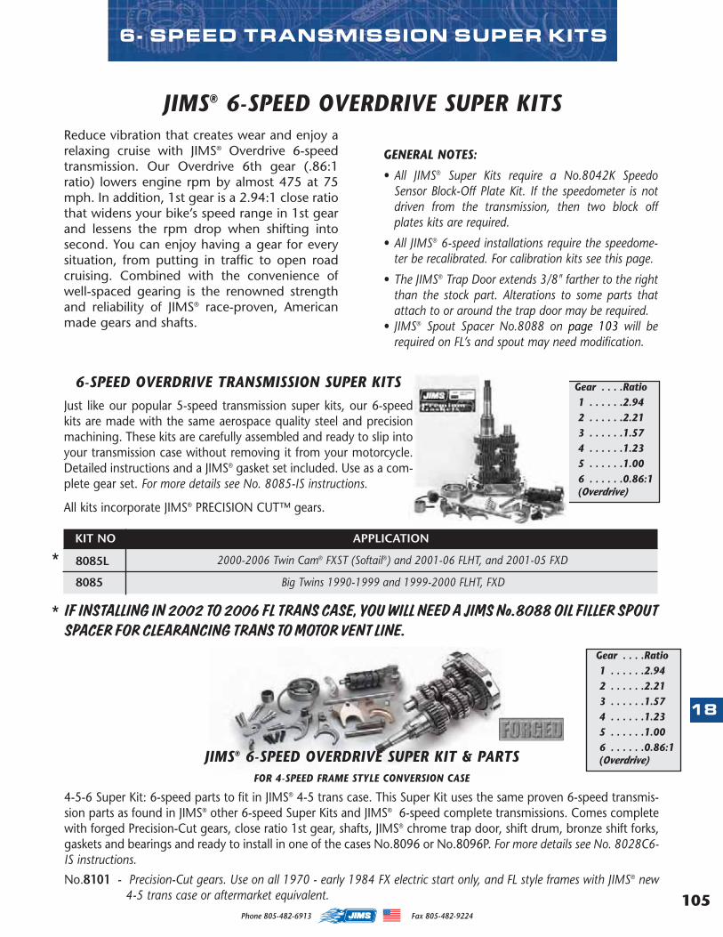
105
18
Phone 805-482-6913 Fax 805-482-9224
Gear . . . .Ratio1 . . . . . .2.942 . . . . . .2.213 . . . . . .1.574 . . . . . .1.235 . . . . . .1.006 . . . . . .0.86:1(Overdrive)
JIMS® 6-SPEED OVERDRIVE SUPER KIT & PARTS FOR 4-SPEED FRAME STYLE CONVERSION CASE
4-5-6 Super Kit: 6-speed parts to fit in JIMS® 4-5 trans case. This Super Kit uses the same proven 6-speed transmis-sion parts as found in JIMS® other 6-speed Super Kits and JIMS® 6-speed complete transmissions. Comes completewith forged Precision-Cut gears, close ratio 1st gear, shafts, JIMS® chrome trap door, shift drum, bronze shift forks,gaskets and bearings and ready to install in one of the cases No.8096 or No.8096P. For more details see No. 8028C6-IS instructions.
No.8101 - Precision-Cut gears. Use on all 1970 - early 1984 FX electric start only, and FL style frames with JIMS® new4-5 trans case or aftermarket equivalent.
Just like our popular 5-speed transmission super kits, our 6-speedkits are made with the same aerospace quality steel and precisionmachining. These kits are carefully assembled and ready to slip intoyour transmission case without removing it from your motorcycle.Detailed instructions and a JIMS® gasket set included. Use as a com-plete gear set. For more details see No. 8085-IS instructions.
6-SPEED OVERDRIVE TRANSMISSION SUPER KITS
KIT NO.
8085
8085L
All kits incorporate JIMS® PRECISION CUT™ gears.
Big Twins 1990-1999 and 1999-2000 FLHT, FXD
2000-2006 Twin Cam® FXST (Softail®) and 2001-06 FLHT, and 2001-05 FXD
IF INSTALLING IN 2002 TO 2006 FL TRANS CASE, YOU WILL NEED A JIMS No.8088 OIL FILLER SPOUTSPACER FOR CLEARANCING TRANS TO MOTOR VENT LINE.
*
*
Gear . . . .Ratio1 . . . . . .2.942 . . . . . .2.213 . . . . . .1.574 . . . . . .1.235 . . . . . .1.006 . . . . . .0.86:1(Overdrive)
6- SPEED TRANSMISSION SUPER KITS
Reduce vibration that creates wear and enjoy arelaxing cruise with JIMS® Overdrive 6-speedtransmission. Our Overdrive 6th gear (.86:1ratio) lowers engine rpm by almost 475 at 75mph. In addition, 1st gear is a 2.94:1 close ratiothat widens your bike’s speed range in 1st gearand lessens the rpm drop when shifting intosecond. You can enjoy having a gear for everysituation, from putting in traffic to open roadcruising. Combined with the convenience ofwell-spaced gearing is the renowned strengthand reliability of JIMS® race-proven, Americanmade gears and shafts.
JIMS® 6-SPEED OVERDRIVE SUPER KITS
GENERAL NOTES:
• All JIMS® Super Kits require a No.8042K SpeedoSensor Block-Off Plate Kit. If the speedometer is notdriven from the transmission, then two block offplates kits are required.
• All JIMS® 6-speed installations require the speedome-ter be recalibrated. For calibration kits see this page.
• The JIMS® Trap Door extends 3/8" farther to the rightthan the stock part. Alterations to some parts thatattach to or around the trap door may be required.
• JIMS® Spout Spacer No.8088 on page 103 will berequired on FL’s and spout may need modification.
APPLICATION
MASTER 2013 CATALOG_JMS 2.qxp:Layout 1 8/2/12 8:27 PM Page 105
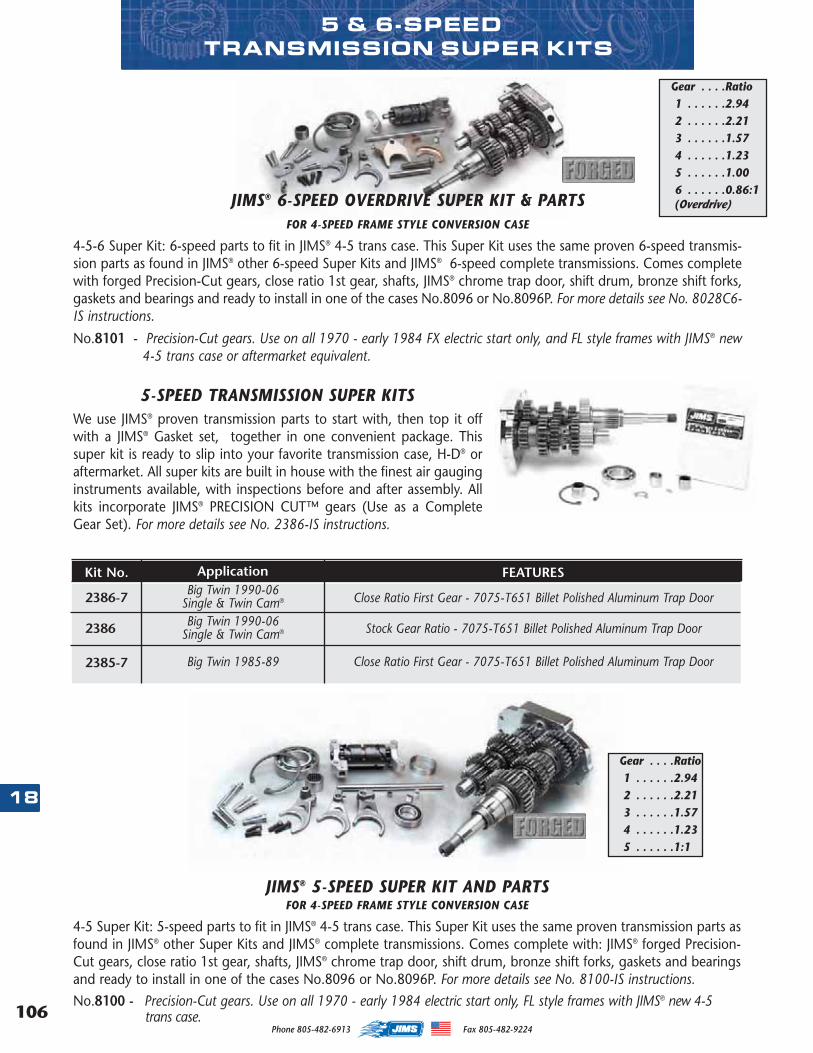
106
18
Phone 805-482-6913 Fax 805-482-9224
We use JIMS® proven transmission parts to start with, then top it offwith a JIMS® Gasket set, together in one convenient package. Thissuper kit is ready to slip into your favorite transmission case, H-D® oraftermarket. All super kits are built in house with the finest air gauginginstruments available, with inspections before and after assembly. Allkits incorporate JIMS® PRECISION CUT™ gears (Use as a CompleteGear Set). For more details see No. 2386-IS instructions.
5-SPEED TRANSMISSION SUPER KITS
Big Twin 1985-89
Kit No.
2385-7
2386
2386-7
Application FEATURES
Close Ratio First Gear - 7075-T651 Billet Polished Aluminum Trap Door
Stock Gear Ratio - 7075-T651 Billet Polished Aluminum Trap Door
Close Ratio First Gear - 7075-T651 Billet Polished Aluminum Trap Door
Big Twin 1990-06Single & Twin Cam®
Big Twin 1990-06Single & Twin Cam®
5 & 6-SPEED TRANSMISSION SUPER KITS
JIMS® 6-SPEED OVERDRIVE SUPER KIT & PARTS FOR 4-SPEED FRAME STYLE CONVERSION CASE
4-5-6 Super Kit: 6-speed parts to fit in JIMS® 4-5 trans case. This Super Kit uses the same proven 6-speed transmis-sion parts as found in JIMS® other 6-speed Super Kits and JIMS® 6-speed complete transmissions. Comes completewith forged Precision-Cut gears, close ratio 1st gear, shafts, JIMS® chrome trap door, shift drum, bronze shift forks,gaskets and bearings and ready to install in one of the cases No.8096 or No.8096P. For more details see No. 8028C6-IS instructions.
No.8101 - Precision-Cut gears. Use on all 1970 - early 1984 FX electric start only, and FL style frames with JIMS® new4-5 trans case or aftermarket equivalent.
Gear . . . .Ratio1 . . . . . .2.942 . . . . . .2.213 . . . . . .1.574 . . . . . .1.235 . . . . . .1.006 . . . . . .0.86:1(Overdrive)
JIMS® 5-SPEED SUPER KIT AND PARTS FOR 4-SPEED FRAME STYLE CONVERSION CASE
4-5 Super Kit: 5-speed parts to fit in JIMS® 4-5 trans case. This Super Kit uses the same proven transmission parts asfound in JIMS® other Super Kits and JIMS® complete transmissions. Comes complete with: JIMS® forged Precision-Cut gears, close ratio 1st gear, shafts, JIMS® chrome trap door, shift drum, bronze shift forks, gaskets and bearingsand ready to install in one of the cases No.8096 or No.8096P. For more details see No. 8100-IS instructions.No.8100 - Precision-Cut gears. Use on all 1970 - early 1984 electric start only, FL style frames with JIMS® new 4-5
trans case.
Gear . . . .Ratio1 . . . . . .2.942 . . . . . .2.213 . . . . . .1.574 . . . . . .1.235 . . . . . .1:1
MASTER 2013 CATALOG_JMS 2.qxp:Layout 1 8/2/12 8:27 PM Page 106
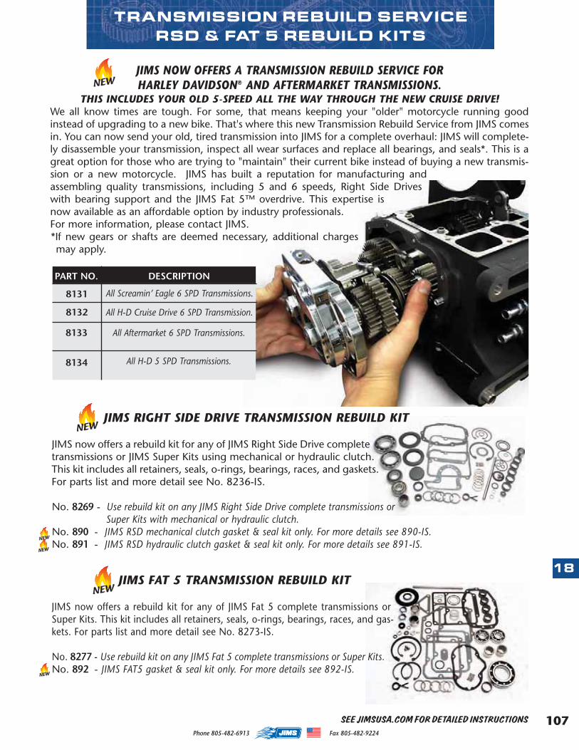
107
18
Phone 805-482-6913 Fax 805-482-9224
TRANSMISSION REBUILD SERVICERSD & FAT 5 REBUILD KITS
SEE JIMSUSA.COM FOR DETAILED INSTRUCTIONS
JIMS NOW OFFERS A TRANSMISSION REBUILD SERVICE FOR HARLEY DAVIDSON® AND AFTERMARKET TRANSMISSIONS.
THIS INCLUDES YOUR OLD 5-SPEED ALL THE WAY THROUGH THE NEW CRUISE DRIVE!We all know times are tough. For some, that means keeping your "older" motorcycle running goodinstead of upgrading to a new bike. That's where this new Transmission Rebuild Service from JIMS comesin. You can now send your old, tired transmission into JIMS for a complete overhaul: JIMS will complete-ly disassemble your transmission, inspect all wear surfaces and replace all bearings, and seals*. This is agreat option for those who are trying to "maintain" their current bike instead of buying a new transmis-sion or a new motorcycle. JIMS has built a reputation for manufacturing andassembling quality transmissions, including 5 and 6 speeds, Right Side Driveswith bearing support and the JIMS Fat 5™ overdrive. This expertise isnow available as an affordable option by industry professionals. For more information, please contact JIMS. *If new gears or shafts are deemed necessary, additional chargesmay apply.
All Screamin’ Eagle 6 SPD Transmissions.
All H-D Cruise Drive 6 SPD Transmission.
All Aftermarket 6 SPD Transmissions.
PART NO.
8131
8132
8133
All H-D 5 SPD Transmissions.8134
DESCRIPTION
NEW
JIMS RIGHT SIDE DRIVE TRANSMISSION REBUILD KIT
JIMS now offers a rebuild kit for any of JIMS Right Side Drive completetransmissions or JIMS Super Kits using mechanical or hydraulic clutch.This kit includes all retainers, seals, o-rings, bearings, races, and gaskets.For parts list and more detail see No. 8236-IS.
No. 8269 - Use rebuild kit on any JIMS Right Side Drive complete transmissions orSuper Kits with mechanical or hydraulic clutch.
No. 890 - JIMS RSD mechanical clutch gasket & seal kit only. For more details see 890-IS.No. 891 - JIMS RSD hydraulic clutch gasket & seal kit only. For more details see 891-IS.
JIMS FAT 5 TRANSMISSION REBUILD KIT
JIMS now offers a rebuild kit for any of JIMS Fat 5 complete transmissions orSuper Kits. This kit includes all retainers, seals, o-rings, bearings, races, and gas-kets. For parts list and more detail see No. 8273-IS.
No. 8277 - Use rebuild kit on any JIMS Fat 5 complete transmissions or Super Kits.No. 892 - JIMS FAT5 gasket & seal kit only. For more details see 892-IS.
NEW
NEW
NEW
NEW
NEW
MASTER 2013 CATALOG_JMS 2.qxp:Layout 1 8/2/12 8:27 PM Page 107
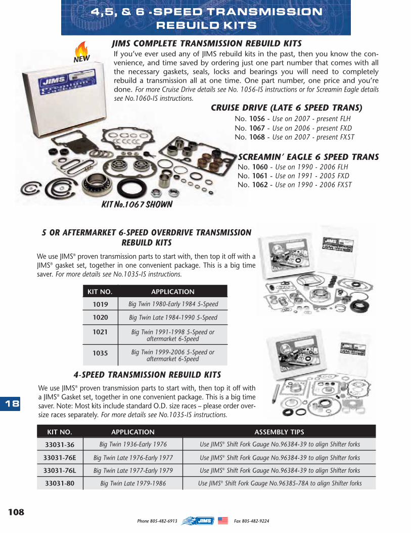
108
18
Phone 805-482-6913 Fax 805-482-9224
We use JIMS® proven transmission parts to start with, then top it off with aJIMS® gasket set, together in one convenient package. This is a big timesaver. For more details see No.1035-IS instructions.
Big Twin 1980-Early 1984 5-Speed
Big Twin Late 1984-1990 5-Speed
Big Twin 1991-1998 5-Speed oraftermarket 6-Speed
KIT NO.
1019
1020
1021
Big Twin 1999-2006 5-Speed oraftermarket 6-Speed
1035
5 OR AFTERMARKET 6-SPEED OVERDRIVE TRANSMISSIONREBUILD KITS
APPLICATION
We use JIMS® proven transmission parts to start with, then top it off witha JIMS® Gasket set, together in one convenient package. This is a big timesaver. Note: Most kits include standard O.D. size races – please order over-size races separately. For more details see No.1035-IS instructions.
4-SPEED TRANSMISSION REBUILD KITS
Big Twin 1936-Early 1976
Big Twin Late 1976-Early 1977
Big Twin Late 1977-Early 1979
KIT NO.
33031-36
33031-76E
33031-76L
APPLICATION ASSEMBLY TIPS
Use JIMS® Shift Fork Gauge No.96384-39 to align Shifter forks
Use JIMS® Shift Fork Gauge No.96384-39 to align Shifter forks
Use JIMS® Shift Fork Gauge No.96384-39 to align Shifter forks
Big Twin Late 1979-198633031-80 Use JIMS® Shift Fork Gauge No.96385-78A to align Shifter forks
4,5, & 6 -SPEED TRANSMISSION REBUILD KITS
NEWIf you’ve ever used any of JIMS rebuild kits in the past, then you know the con-venience, and time saved by ordering just one part number that comes with allthe necessary gaskets, seals, locks and bearings you will need to completelyrebuild a transmission all at one time. One part number, one price and you’redone. For more Cruise Drive details see No. 1056-IS instructions or for Screamin Eagle detailssee No.1060-IS instructions.
CRUISE DRIVE (LATE 6 SPEED TRANS)No. 1056 - Use on 2007 - present FLH No. 1067 - Use on 2006 - present FXDNo. 1068 - Use on 2007 - present FXST
SCREAMIN’ EAGLE 6 SPEED TRANSNo. 1060 - Use on 1990 - 2006 FLHNo. 1061 - Use on 1991 - 2005 FXDNo. 1062 - Use on 1990 - 2006 FXST
JIMS COMPLETE TRANSMISSION REBUILD KITS
KIT No.1067 SHOWN
MASTER 2013 CATALOG_JMS 2.qxp:Layout 1 8/2/12 8:27 PM Page 108
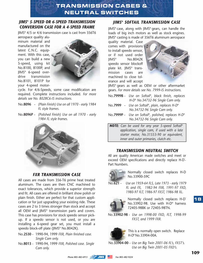
109
18
Phone 805-482-6913 Fax 805-482-9224
TRANSMISSION CASES & NEUTRAL SWITCHES
JIMS® 5-SPEED OR 6-SPEED TRANSMISSIONCONVERSION CASE FOR A 4-SPEED FRAME
JIMS® 4/5 or 4/6 transmission case is cast from 356T6aerospace quality alu-minum material andmanufactured on thelatest C.N.C. equip-ment. With this case,you can build a new5-speed, using kitNo.8100, 8100P, andJIMS® 6-speed over-drive transmissionNo.8101, 8101P foryour 4-speed motor-cycle. For 4/6-Speeds, some case modification arerequired. Complete instructions included. For moredetails see No. 8028C6-IS instructions.
No.8096 - (Plain Finish) Use on all 1970 - early 1984FL style frames.
No.8096P - (Polished Finish) Use on all 1970 - early1984 FL style frames.
FXR TRANSMISSION CASEAll cases are made from 356-T6 prime heat treatedaluminum. The cases are then CNC machined toexact tolerances, which provide a superior strengthand fit. All cases are offered in brilliant show polish orplain finish. Either are perfect for that custom appli-cation or for just upgrading your existing ride. Thesecases are 2 to 3 times stronger than stock and acceptall OEM and JIMS® transmission parts and covers.This case has provisions for stock speedo sensor pick-up. If a speedo sensor is not used, or you areinstalling a 6-speed gear set, you must install aspeedo block-off plate (JIMS® No.8042K).
No.2530 - 1990-94, 1999 FXR, Plain finished case.Single Cam only.
No.8013 - 1990-94, 1999 FXR, Polished case. SingleCam only.
NOTE: Can be used for any year 5-speed Softail®
application, single cam, if used with a latestarter motor, No.31553-90 or equivalent,inner and outer primaries, clutch etc.
JIMS® SOFTAIL TRANSMISSION CASEJIMS® case, along with JIMS® gears, can handle theloads of big inch motors as well as stock engines.JIMS® casting is made of 356T6 aluminum aerospacequality material. Casecomes with provisionsto install speedo sensor,or if not used orderJIMS® No.8042Kspeedo sensor blockoffplate kit. JIMS® trans-mission cases aremachined to close tol-erance and will acceptJIMS® gears as well as OEM or other aftermarketgears. For more details see No. 7999-IS instructions.
No.7999B - Use on Softail®, black finish, replacesH-D® No.34732-96 Single Cam only.
No.7999 - Use on Softail®, plain, replaces H-D®
No.34732-96 Single Cam only.No.7999P - Use on Softail®, polished, replaces H-D®
No.34732-96 Single Cam only.
Normally closed switch replaces H-DNo.33900-59C
TRANSMISSION NEUTRAL SWITCHAll are quality American made switches and meet orexceed OEM specifications and directly replace H-D
®
-Part Numbers.
No.621 - Use on 1959-64 FLS, Late 1973 - early 1979FL and FX, 1982-94 FXR, 1991-97 FXD,1980-97 FLT, 1986-97 FXST, 1986-98 XL.
Normally closed switch replaces H-D®
No.33902-98. Use with H-D® harness72405-98BK or 72405-98TN.
No.33902-98 - Use on 1998-00 FXD, FLT, 1998-99FXST, and 1999 FXR.
This is a normally open switch. ReplaceH-D® No.33904-00A.
No.33904-00 - Use on Big Twin 2001-06 FL’s, FXST’s. Use on Big Twin 2001-05 FXD’s.
MASTER 2013 CATALOG_JMS 2.qxp:Layout 1 8/2/12 8:27 PM Page 109
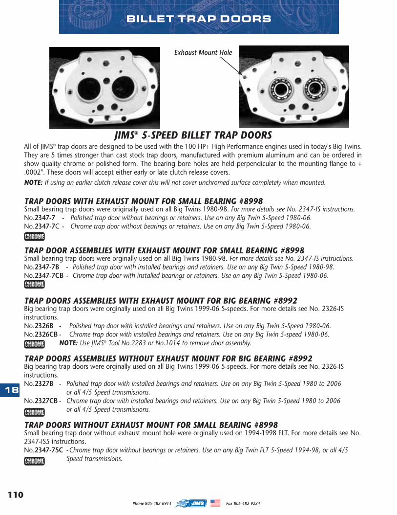
110
18
Phone 805-482-6913 Fax 805-482-9224
TRAP DOORS WITH EXHAUST MOUNT FOR SMALL BEARING #8998Small bearing trap doors were originally used on all Big Twins 1980-98. For more details see No. 2347-IS instructions.No.2347-7 - Polished trap door without bearings or retainers. Use on any Big Twin 5-Speed 1980-06. No.2347-7C - Chrome trap door without bearings or retainers. Use on any Big Twin 5-Speed 1980-06.
TRAP DOOR ASSEMBLIES WITH EXHAUST MOUNT FOR SMALL BEARING #8998Small bearing trap doors were orginally used on all Big Twins 1980-98. For more details see No. 2347-IS instructions.No.2347-7B - Polished trap door with installed bearings and retainers. Use on any Big Twin 5-Speed 1980-98. No.2347-7CB - Chrome trap door with installed bearings or retainers. Use on any Big Twin 5-Speed 1980-06.
TRAP DOORS ASSEMBLIES WITH EXHAUST MOUNT FOR BIG BEARING #8992Big bearing trap doors were orginally used on all Big Twins 1999-06 5-speeds. For more details see No. 2326-ISinstructions.No.2326B - Polished trap door with installed bearings and retainers. Use on any Big Twin 5-Speed 1980-06. No.2326CB - Chrome trap door with installed bearings and retainers. Use on any Big Twin 5-speed 1980-06.
NOTE: Use JIMS® Tool No.2283 or No.1014 to remove door assembly.
TRAP DOORS ASSEMBLIES WITHOUT EXHAUST MOUNT FOR BIG BEARING #8992Big bearing trap doors were orginally used on all Big Twins 1999-06 5-speeds. For more details see No. 2326-ISinstructions.No.2327B - Polished trap door with installed bearings and retainers. Use on any Big Twin 5-Speed 1980 to 2006
or all 4/5 Speed transmissions.No.2327CB - Chrome trap door with installed bearings and retainers. Use on any Big Twin 5-Speed 1980 to 2006
or all 4/5 Speed transmissions.
TRAP DOORS WITHOUT EXHAUST MOUNT FOR SMALL BEARING #8998Small bearing trap door without exhaust mount hole were orginally used on 1994-1998 FLT. For more details see No.2347-IS5 instructions.No.2347-75C -Chrome trap door without bearings or retainers. Use on any Big Twin FLT 5-Speed 1994-98, or all 4/5
Speed transmissions.
Exhaust Mount Hole
JIMS® 5-SPEED BILLET TRAP DOORSAll of JIMS® trap doors are designed to be used with the 100 HP+ High Performance engines used in today's Big Twins.They are 5 times stronger than cast stock trap doors, manufactured with premium aluminum and can be ordered inshow quality chrome or polished form. The bearing bore holes are held perpendicular to the mounting flange to +.0002". These doors will accept either early or late clutch release covers. NOTE: If using an earlier clutch release cover this will not cover unchromed surface completely when mounted.
BILLET TRAP DOORS
MASTER 2013 CATALOG_JMS 2.qxp:Layout 1 8/2/12 8:27 PM Page 110
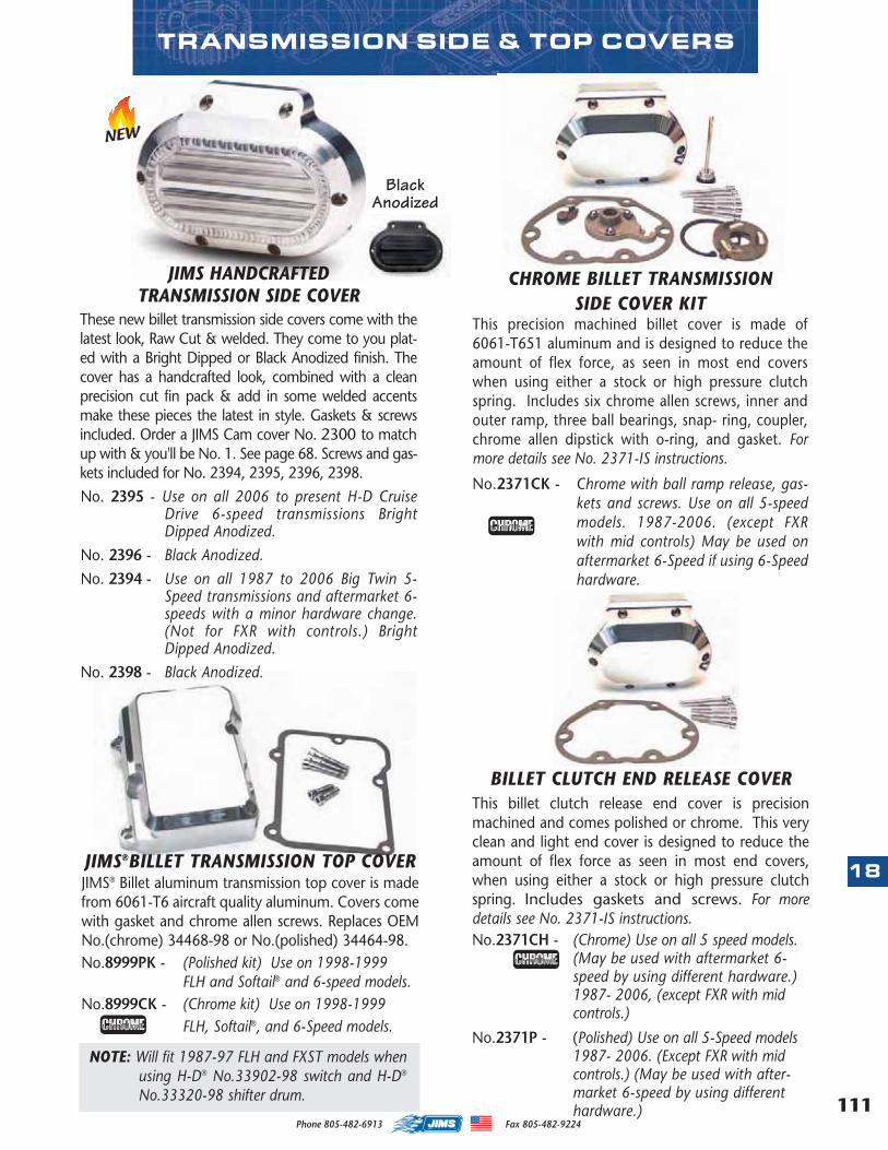
BILLET CLUTCH END RELEASE COVERThis billet clutch release end cover is precisionmachined and comes polished or chrome. This veryclean and light end cover is designed to reduce theamount of flex force as seen in most end covers,when using either a stock or high pressure clutchspring. Includes gaskets and screws. For moredetails see No. 2371-IS instructions.No.2371CH - (Chrome) Use on all 5 speed models.
(May be used with aftermarket 6-speed by using different hardware.)1987- 2006, (except FXR with midcontrols.)
No.2371P - (Polished) Use on all 5-Speed models1987- 2006. (Except FXR with midcontrols.) (May be used with after-market 6-speed by using differenthardware.) 111
18
Phone 805-482-6913 Fax 805-482-9224
CHROME BILLET TRANSMISSION SIDE COVER KIT
This precision machined billet cover is made of6061-T651 aluminum and is designed to reduce theamount of flex force, as seen in most end coverswhen using either a stock or high pressure clutchspring. Includes six chrome allen screws, inner andouter ramp, three ball bearings, snap- ring, coupler,chrome allen dipstick with o-ring, and gasket. Formore details see No. 2371-IS instructions.
No.2371CK - Chrome with ball ramp release, gas-kets and screws. Use on all 5-speedmodels. 1987-2006. (except FXRwith mid controls) May be used onaftermarket 6-Speed if using 6-Speedhardware.
TRANSMISSION SIDE & TOP COVERS
NEW
JIMS®BILLET TRANSMISSION TOP COVERJIMS® Billet aluminum transmission top cover is madefrom 6061-T6 aircraft quality aluminum. Covers comewith gasket and chrome allen screws. Replaces OEMNo.(chrome) 34468-98 or No.(polished) 34464-98. No.8999PK - (Polished kit) Use on 1998-1999
FLH and Softail® and 6-speed models.No.8999CK - (Chrome kit) Use on 1998-1999
FLH, Softail®, and 6-Speed models.
NOTE: Will fit 1987-97 FLH and FXST models whenusing H-D® No.33902-98 switch and H-D®
No.33320-98 shifter drum.
JIMS HANDCRAFTED TRANSMISSION SIDE COVER
These new billet transmission side covers come with thelatest look, Raw Cut & welded. They come to you plat-ed with a Bright Dipped or Black Anodized finish. Thecover has a handcrafted look, combined with a cleanprecision cut fin pack & add in some welded accentsmake these pieces the latest in style. Gaskets & screwsincluded. Order a JIMS Cam cover No. 2300 to matchup with & you'll be No. 1. See page 68. Screws and gas-kets included for No. 2394, 2395, 2396, 2398.No. 2395 - Use on all 2006 to present H-D Cruise
Drive 6-speed transmissions BrightDipped Anodized.
No. 2396 - Black Anodized.No. 2394 - Use on all 1987 to 2006 Big Twin 5-
Speed transmissions and aftermarket 6-speeds with a minor hardware change.(Not for FXR with controls.) BrightDipped Anodized.
No. 2398 - Black Anodized.
BlackAnodized
MASTER 2013 CATALOG_JMS 2.qxp:Layout 1 8/2/12 8:27 PM Page 111
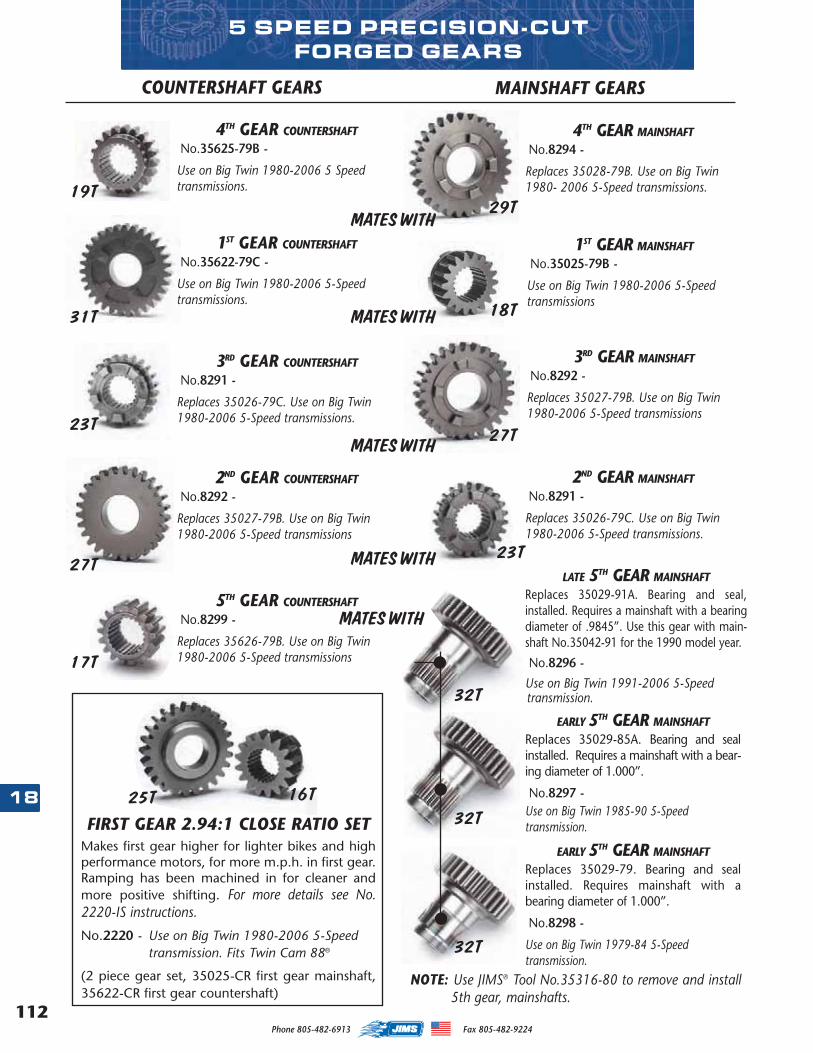
112
18
Phone 805-482-6913 Fax 805-482-9224
LATE 5TH GEAR MAINSHAFTReplaces 35029-91A. Bearing and seal,installed. Requires a mainshaft with a bearingdiameter of .9845”. Use this gear with main-shaft No.35042-91 for the 1990 model year.
No.8296 -
Use on Big Twin 1991-2006 5-Speed transmission.
4TH GEAR MAINSHAFTNo.8294 -
Replaces 35028-79B. Use on Big Twin 1980- 2006 5-Speed transmissions.
MAINSHAFT GEARSCOUNTERSHAFT GEARS
1ST GEAR MAINSHAFTNo.35025-79B -
Use on Big Twin 1980-2006 5-Speed transmissions
3RD GEAR MAINSHAFTNo.8292 -
Replaces 35027-79B. Use on Big Twin1980-2006 5-Speed transmissions
2ND GEAR MAINSHAFTNo.8291 -
Replaces 35026-79C. Use on Big Twin 1980-2006 5-Speed transmissions.
EARLY 5TH GEAR MAINSHAFTReplaces 35029-79. Bearing and sealinstalled. Requires mainshaft with abearing diameter of 1.000”.
No.8298 -
Use on Big Twin 1979-84 5-Speed transmission.
FIRST GEAR 2.94:1 CLOSE RATIO SETMakes first gear higher for lighter bikes and highperformance motors, for more m.p.h. in first gear.Ramping has been machined in for cleaner andmore positive shifting. For more details see No.2220-IS instructions.
No.2220 - Use on Big Twin 1980-2006 5-Speedtransmission. Fits Twin Cam 88®
(2 piece gear set, 35025-CR first gear mainshaft,35622-CR first gear countershaft)
1ST GEAR COUNTERSHAFTNo.35622-79C -
Use on Big Twin 1980-2006 5-Speed transmissions.
3RD GEAR COUNTERSHAFTNo.8291 -
Replaces 35026-79C. Use on Big Twin1980-2006 5-Speed transmissions.
4TH GEAR COUNTERSHAFTNo.35625-79B -
Use on Big Twin 1980-2006 5 Speedtransmissions.
5TH GEAR COUNTERSHAFTNo.8299 -
Replaces 35626-79B. Use on Big Twin 1980-2006 5-Speed transmissions
2ND GEAR COUNTERSHAFTNo.8292 -
Replaces 35027-79B. Use on Big Twin1980-2006 5-Speed transmissions
EARLY 5TH GEAR MAINSHAFTReplaces 35029-85A. Bearing and sealinstalled. Requires a mainshaft with a bear-ing diameter of 1.000”.
No.8297 -Use on Big Twin 1985-90 5-Speed transmission.
NOTE: Use JIMS® Tool No.35316-80 to remove and install5th gear, mainshafts.
5 SPEED PRECISION-CUTFORGED GEARS
MATES WITH
MATES WITH
MATES WITH
MATES WITH
MATES WITH
19T
31T
23T
27T
17T
25T 16T
29T
18T
27T
23T
32T
32T
32T
MASTER 2013 CATALOG_JMS 2.qxp:Layout 1 8/2/12 8:27 PM Page 112
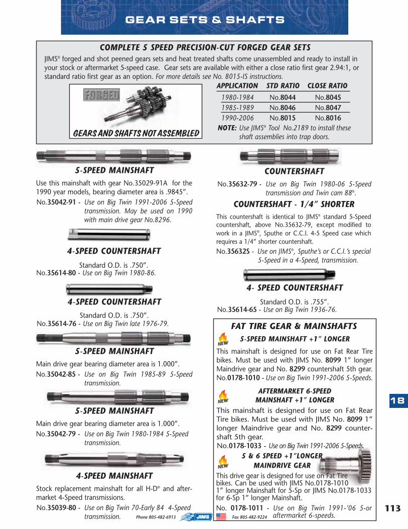
113
18
Phone 805-482-6913 Fax 805-482-9224
GEAR SETS & SHAFTS
COUNTERSHAFTNo.35632-79 - Use on Big Twin 1980-06 5-Speed
transmission and Twin cam 88®.
APPLICATION STD RATIO CLOSE RATIO
1980-1984 No.8044 No.80451985-1989 No.8046 No.80471990-2006 No.8015 No.8016
GEARS AND SHAFTS NOT ASSEMBLED
5-SPEED MAINSHAFTMain drive gear bearing diameter area is 1.000”.No.35042-85 - Use on Big Twin 1985-89 5-Speed
transmission.
4-SPEED MAINSHAFTStock replacement mainshaft for all H-D® and after-market 4-Speed transmissions. No.35039-80 - Use on Big Twin 70-Early 84 4-Speed
transmission.
COUNTERSHAFT - 1/4” SHORTERThis countershaft is identical to JIMS® standard 5-Speedcountershaft, above No.35632-79, except modified towork in a JIMS®, Sputhe or C.C.I. 4-5 Speed case whichrequires a 1/4” shorter countershaft. No.35632S - Use on JIMS®, Sputhe’s or C.C.I.’s special
5-Speed in a 4-Speed, transmission.
5-SPEED MAINSHAFTMain drive gear bearing diameter area is 1.000”.No.35042-79 - Use on Big Twin 1980-1984 5-Speed
transmission.
5-SPEED MAINSHAFTUse this mainshaft with gear No.35029-91A for the1990 year models, bearing diameter area is .9845”.No.35042-91 - Use on Big Twin 1991-2006 5-Speed
transmission. May be used on 1990with main drive gear No.8296.
4-SPEED COUNTERSHAFT
Standard O.D. is .750”.No.35614-76 - Use on Big Twin late 1976-79.
4-SPEED COUNTERSHAFT
Standard O.D. is .750”.No.35614-80 - Use on Big Twin 1980-86.
COMPLETE 5 SPEED PRECISION-CUT FORGED GEAR SETS JIMS® forged and shot peened gears sets and heat treated shafts come unassembled and ready to install inyour stock or aftermarket 5-speed case. Gear sets are available with either a close ratio first gear 2.94:1, orstandard ratio first gear as an option. For more details see No. 8015-IS instructions.
NOTE: Use JIMS® Tool No.2189 to install theseshaft assemblies into trap doors.
5-SPEED MAINSHAFT +1” LONGER
This mainshaft is designed for use on Fat Rear Tirebikes. Must be used with JIMS No. 8099 1” longerMaindrive gear and No. 8299 countershaft 5th gear.No.0178-1010 - Use on Big Twin 1991-2006 5-Speeds.
NEW
NEW
4- SPEED COUNTERSHAFT
Standard O.D. is .755”.No.35614-65 - Use on Big Twin 1936-76.
NEW
5 & 6 SPEED +1”LONGER MAINDRIVE GEAR
This drive gear is designed for use on Fat Tirebikes. Can be used with JIMS No.0178-10101” longer Mainshaft for 5-Sp or JIMS No.0178-1033for 6-Sp 1” longer Mainshaft. No. 0178-1011 - Use on Big Twin 1991-’06 5-or
aftermarket 6-speeds.
AFTERMARKET 6-SPEED MAINSHAFT +1” LONGER
This mainshaft is designed for use on Fat RearTire bikes. Must be used with JIMS No. 8099 1”longer Maindrive gear and No. 8299 counter-shaft 5th gear. No.0178-1033 - Use on Big Twin 1991-2006 5-Speeds.
FAT TIRE GEAR & MAINSHAFTS
MASTER 2013 CATALOG_JMS 2.qxp:Layout 1 8/2/12 8:27 PM Page 113
114
18
Phone 805-482-6913 Fax 805-482-9224
LATE 4-SPEED BIG TWIN ANDSPORTSTER® COUNTERSHAFT BEARING
American made by Torrington®
. For the best resultsinstall bearing with JIMS
®
Countershaft Bearing ToolNo.34733-77.No.35961-52 - Use on Big Twin Late 1977-84, 2 per
transmission. Use on Sportster® 1954-1984, 2 per trans. Use on Sportster®
1985-1990, 3 per trans. Use on Buell®
1987-90, 3 per transmission.
LATE 4-SPEED BIG TWIN MAIN DRIVEGEAR BEARING
American made by Torrington®
. For the best resultsinstall bearing with JIMS
®
Transmission Main DriveGear Bearing Tool No.33428-78.No.8905 - Use on Big Twin Late 1977-81.
CLOSED END SPORTSTER®
COUNTERSHAFT CASE BEARINGAmerican made by Torrington
®
.No.35960-54 - Use on Sportster® and K models
1954-90. Use on Buell®
1987-90.
PRIMARY & TRANSMISSION BEARINGS
SPLIT NEEDLE BEARING Mainshaft - Countershaft bearing, 4 used per trans-mission - Sold Individually.No.8876A - Use on all Big Twin 5-Speeds, or after-
market 6-Speeds, 1980-2006.
SPORTSTER® MAINSHAFT RIGHT CASE BEARING
American made by Torrington®
. Install bearing withJIMS
®
Mainshaft Bearing Tool No.34810-84.No.9118 - Use on Sportster® 1984-90.
Use on Buell®
1987-90.
CLUTCH RELEASE BEARING KITKit comes with U.S.A. made bearing. Since thiskit is made to JIMS® high standards, it ensuresproper clutch operation. Replaces H-D® No.’s37312-75, 37313-80 and 11096.No.2226 -- Use on Big Twin 1975-present 4, 5, and 6-
Speed transmissions. Includes Twin Cam®
Cruise Drive A and B motors.
Thinking of running an open primary system, or look-ing for added durability in your high output engine?JIMS now has a new double row ball bearing with sealand retaining ring kit. Remove stock primary bearingwith JIMS Tool No. 967 and remove bearing race frommain shaft with JIMS Tool No. 34902-84. For moredetails see No. 8960-IS instructions.
No. 8960 - Use on 1990 to 2006 FLH & FXST, and on1990 to 2005 Dyna models or any 5 oraftermarket 6-speeds using H-D bearingNo.9135 (capatiable with Bandit clutchkits).
No. 8961 - Seal for No.8960 kit above.
NEW
INNER PRIMARY BEARING UPGRADE KIT
NEW
MASTER 2013 CATALOG_JMS 2.qxp:Layout 1 8/14/12 8:42 PM Page 114
115
18
Phone 805-482-6913 Fax 805-482-9224
4 SPEED TRANSMISSION CASE BEARINGQuality mainshaft ball bearing. Manufactured in USA.No.9020 - Use on Big Twin 1936-86 4-Speed.
FIFTH GEAR BEARINGUse in fifth gear - 2 per transmission. Install withJIMS® Tool No.34734-80 to the right depth. See"Transmission Tool" section.No.8904 - Use on Big Twin 1980-90.
COUNTERSHAFT BEARINGCountershaft end bearing - Primary side.No.8977 - Use on Big Twin EVO 1980-1999.
Use on 5-Speed Twin Cam® 1999-2006.Use on Sportster® 1991-2005.Use on Buell
®
1991-2005.
FIFTH GEAR BEARING Use in fifth gear - 2 per transmission. Install withJIMS® Tool No.37842-91 to the right depth. See"Transmission Tool" section.No.35051-89 - Use on all Big Twin 1991-06 FL, FXST
and 1991-05 FXR and FXD. Use on Sportster® 1991-present.Use on Buell
®
1991-present.
TRANSMISSION BEARINGS
5-SPEED LATE LARGE DOOR BEARINGUse on all 5 and 6 speed transmissions that usethe larger O.D. (2.047”) door (H-D® No.8992A)bearing. These bearings support the mainshaftand countershafts from the door side of all JIMS®
standard left side drive 5 and 6 speed transmis-sions, and JIMS® billet doors requiring this largebearing. Use JIMS® Tool No.1014 to remove andinstall bearings. Sold in a pack of 2.
No.8992K - Use on all 1999-2005 FXD and 1999-2006,FXST and FLH.
5-SPEED TRANSMISSIONCASE BEARINGManufactured in USA, this bear-ing must be replaced every time the main drivegear is replaced. Use JIMS® No.35316-80 forinstalling bearing and main drive gear, See"Transmission Tool" section. This bearing mustbe installed with the proper tool.No.8978 - Use on Big Twin 1980-Early 1984
5-Speed transmission.
5-SPEED TRAPDOOR BEARINGUse on all 5-Speedtransmissions. Thesequality American bearings (H-D® No.8998) sup-port the transmission main and counter shafts.Use one on countershaft of Buell® and XL. UseJIMS® Tool No.1014 on Big Twin to remove andinstall bearings. Sold in a pack of 2.
No.8998K - Use on Big Twin 1980-1998 5-Speed trans-mission, Sportster® 1991-2003.Use on Buell® 1991-2005.
5-SPEED TRANSMISSIONCASE MAIN GEAR BEARINGQuality main drive gear transmission bearing,manufactured in USA. This bearing must bereplaced whenever the main drive gear isreplaced. Use JIMS® tool No.35316-80 on BigTwin, See "Transmission Tool" section. Thisbearing must be installed with the proper tool.Replaces H-D® No.8996A.No.8996 - Use on Big Twin Late 1984-2006
5-Speed transmission, also Sportster & Buell1991 to 2005.
MASTER 2013 CATALOG_JMS 2.qxp:Layout 1 8/2/12 8:27 PM Page 115
116
18
Phone 805-482-6913 Fax 805-482-9224
TRANSMISSION MAIN BEARING RACEStandard O.D. is 2.314”, I.D. is 1.8802”. It willdepend on the amount of press fit and will deter-mine the amount of line lapping required to fit newbearing and mainshaft.No.35125-37 - Use on Big Twin 1937-Early 1977.No.35125-372 - Oversize +.002”.No.35125-375 - Oversize +.005”.No.35125-3710 - Oversize +.010”.
SPORTSTER® 4-SPEED MAINSHAFT END BEARING
These rollers are made in the USA to JIMS®
specifica-tions from aerospace quality 52100 bearing material.Sold in packs of 100 pcs.
Use on Sportster® 1952-Early 84.
JIMS®
No. SIZE O.D.
9095 STD .1562”9096 +.0004” .1566”9097 +.0008” .1570”
BIG TWIN 4-SPEED MAIN DRIVE GEARAND COUNTERSHAFT ROLLER BEARINGS
These rollers are made in the USA to JIMS® specifica-tions from aerospace quality 52100 bearing material.Standard bearing O.D. is .125” x 2” = .250”. Andwith a main drive gear of 1.6290” to 1.6295” you geta total diameter of 1.8790” to 1.8795”. For a runningclearance of .0005” to .0019”, lap case race to a sizeof 1.8795” (if your total diameter is 1.8790”). If yourtotal diameter is 1.8795” lap to 1.880” and so on foroversize rollers. If using oversize rollers it is ok to leaveout 1 roller, from 44 to 43. In some applications 43rollers is all that will fit without force. Also, use forcountershaft bearings with a standard bearing O.D. of.125” x 2” = .250”. With a countershaft size of .7545”to .7550” you will have a total diameter of 1.0045”to 1.0050” for a running clearance of .0005” to.0019”. Your countershaft gear I.D. should be 1.0050”to 1.069”, use oversize as needed. Sold in packs of 100 pcs.
Use on Big Twin 1936-early 1977 4-Speeds MainDrive Gear.Use on Big Twin 1936-early 1976 4-SpeedsCountershafts.
JIMS®
No. SIZE O.D.
9084 STD .1250”9085 +.0004” .1254”9086 +.0008” .1258”9084A +.001” .1260”
ROLLER BEARINGS & RACES
MAINSHAFT INNER RACEInner primary race - pressed on mainshaft. Press onmainshaft with JIMS® Tool No.34902-84. See "Transmission Tool" section.No.34091-85 - Use on EVO Big Twin Late 1984-
2000. Use on Twin Cam® 1999-2006 5-Speeds or aftermarket6-Speeds.
TRANSMISSION MAIN BEARINGRACE
Standard O.D. is 1.5635”, I.D. is 1.3045”. Theamount of the press fit in the trans case willdetermine the amount of line lapping requiredto fit new bearing and mainshaft. Use JIMS®
Tool No.34810-84 to install race.No.35105-52 - Use on Sportster® and K
Model 1954-83.No.35105-525 - Oversize +.005”.
MASTER 2013 CATALOG_JMS 2.qxp:Layout 1 8/2/12 8:27 PM Page 116
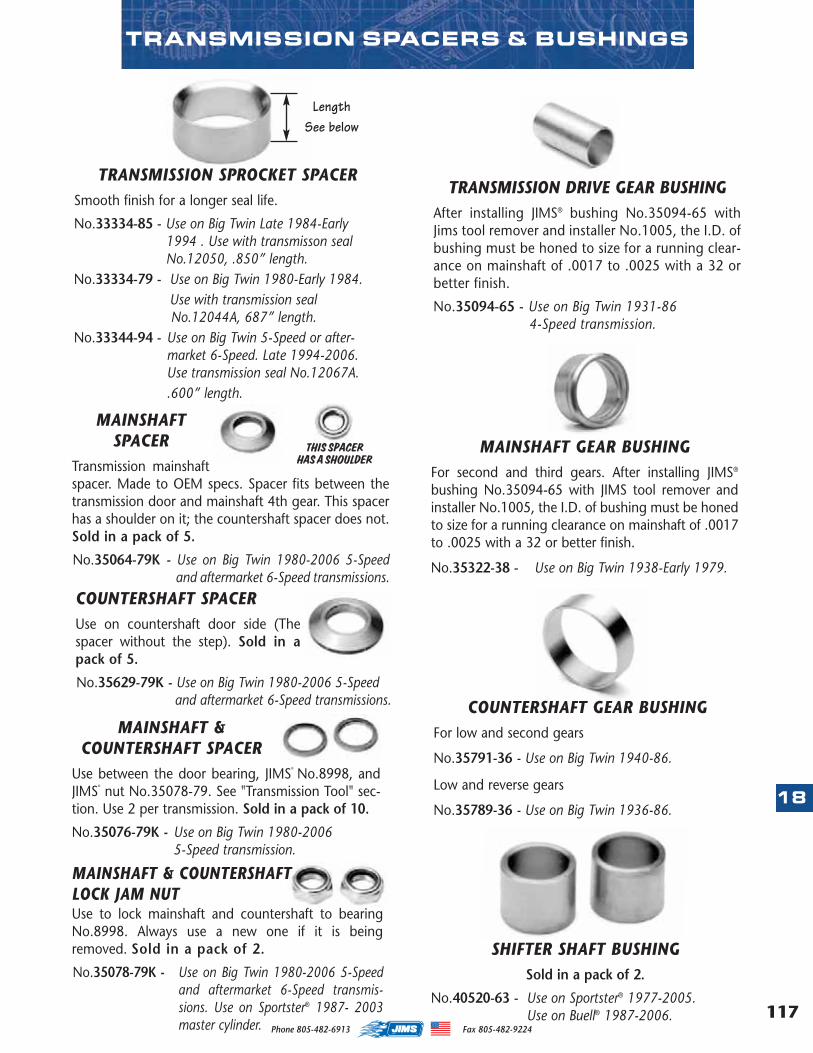
117
18
Phone 805-482-6913 Fax 805-482-9224
MAINSHAFTSPACER
Transmission mainshaftspacer. Made to OEM specs. Spacer fits between thetransmission door and mainshaft 4th gear. This spacerhas a shoulder on it; the countershaft spacer does not.Sold in a pack of 5.
No.35064-79K - Use on Big Twin 1980-2006 5-Speedand aftermarket 6-Speed transmissions.
MAINSHAFT &COUNTERSHAFT SPACER
Use between the door bearing, JIMS®
No.8998, andJIMS
®
nut No.35078-79. See "Transmission Tool" sec-tion. Use 2 per transmission. Sold in a pack of 10.
No.35076-79K - Use on Big Twin 1980-20065-Speed transmission.
TRANSMISSION DRIVE GEAR BUSHINGAfter installing JIMS® bushing No.35094-65 withJims tool remover and installer No.1005, the I.D. ofbushing must be honed to size for a running clear-ance on mainshaft of .0017 to .0025 with a 32 orbetter finish.
No.35094-65 - Use on Big Twin 1931-86 4-Speed transmission.
MAINSHAFT GEAR BUSHINGFor second and third gears. After installing JIMS®
bushing No.35094-65 with JIMS tool remover andinstaller No.1005, the I.D. of bushing must be honedto size for a running clearance on mainshaft of .0017to .0025 with a 32 or better finish.
No.35322-38 - Use on Big Twin 1938-Early 1979.
TRANSMISSION SPACERS & BUSHINGS
TRANSMISSION SPROCKET SPACER Smooth finish for a longer seal life.
No.33334-85 - Use on Big Twin Late 1984-Early1994 . Use with transmisson sealNo.12050, .850” length.
No.33334-79 - Use on Big Twin 1980-Early 1984. Use with transmission sealNo.12044A, 687” length.
No.33344-94 - Use on Big Twin 5-Speed or after-market 6-Speed. Late 1994-2006.Use transmission seal No.12067A..600” length.
Length See below
COUNTERSHAFT GEAR BUSHINGFor low and second gears
No.35791-36 - Use on Big Twin 1940-86.
Low and reverse gears
No.35789-36 - Use on Big Twin 1936-86.
THIS SPACER HAS A SHOULDER
COUNTERSHAFT SPACERUse on countershaft door side (Thespacer without the step). Sold in apack of 5.
No.35629-79K - Use on Big Twin 1980-2006 5-Speedand aftermarket 6-Speed transmissions.
MAINSHAFT & COUNTERSHAFT LOCK JAM NUTUse to lock mainshaft and countershaft to bearingNo.8998. Always use a new one if it is beingremoved. Sold in a pack of 2.
No.35078-79K - Use on Big Twin 1980-2006 5-Speedand aftermarket 6-Speed transmis-sions. Use on Sportster® 1987- 2003master cylinder.
SHIFTER SHAFT BUSHINGSold in a pack of 2.
No.40520-63 - Use on Sportster® 1977-2005.Use on Buell® 1987-2006.
MASTER 2013 CATALOG_JMS 2.qxp:Layout 1 8/2/12 8:27 PM Page 117
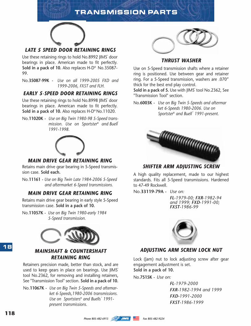
118
18
Phone 805-482-6913 Fax 805-482-9224
EARLY 5-SPEED DOOR RETAINING RINGSUse these retaining rings to hold No.8998 JIMS
®
doorbearings in place. American made to fit perfectly.Sold in a pack of 10. Also replaces H-D® No.11020.
No.11020K - Use on Big Twin 1980-98 5-Speed trans-mission. Use on Sportster® and Buell
®
1991-1998.
MAIN DRIVE GEAR RETAINING RINGRetains main drive gear bearing in early style 5-Speedtransmission case. Sold in a pack of 10.
No.11057K - Use on Big Twin 1980-early 19845-Speed transmission.
MAINSHAFT & COUNTERSHAFTRETAINING RING
Retainers precision made, better than stock, and areused to keep gears in place on bearings. Use JIMS
®
tool No.2362, for removing and installing retainers,See "Transmission Tool" section. Sold in a pack of 10.
No.11067K - Use on Big Twin 5-Speeds and aftemar-ket 6-Speeds,1980-2006 transmissions.Use on Sportsters® and Buells
®
1991-present transmissions.
MAIN DRIVE GEAR RETAINING RINGRetains main drive gear bearing in 5-Speed transmis-sion case. Sold each.
No.11161 - Use on Big Twin Late 1984-2006 5-Speedand aftermarket 6-Speed transmissions.
THRUST WASHERUse on 5-Speed transmission shafts where a retainerring is positioned. Use between gear and retainerring. For a 5-Speed transmission, washers are .070”thick for the best end play control. Sold in a pack of 5. Use with JIMS
®
tool No.2362, See"Transmission Tool" section.
No.6003K - Use on Big Twin 5-Speeds and aftermarket 6-Speeds 1980-2006. Use on Sportster® and Buell
®
1991-present.
TRANSMISSION PARTS
LATE 5 SPEED DOOR RETAINING RINGSUse these retaining rings to hold No.8992 JIMS
®
doorbearings in place. American made to fit perfectly.Sold in a pack of 10. Also replaces H-D® No.35087-99.
No.35087-99K - Use on all 1999-2005 FXD and1999-2006, FXST and FLH.
ADJUSTING ARM SCREW LOCK NUT
Lock (Jam) nut to lock adjusting screw after gearengagement adjustment is set. Sold in a pack of 10.
No.7515K - Use on: FL-1979-2000FXR-1982-1994 and 1999FXD-1991-2000FXST-1986-1999
SHIFTER ARM ADJUSTING SCREWA high quality replacement, made to our higheststandards. Fits all 5-Speed transmissions. Hardenedto 47-49 Rockwell.No.33119-79A - Use on:
FL-1979-00; FXR-1982-94and 1999; FXD-1991-00;FXST-1986-99
MASTER 2013 CATALOG_JMS 2.qxp:Layout 1 8/2/12 8:27 PM Page 118
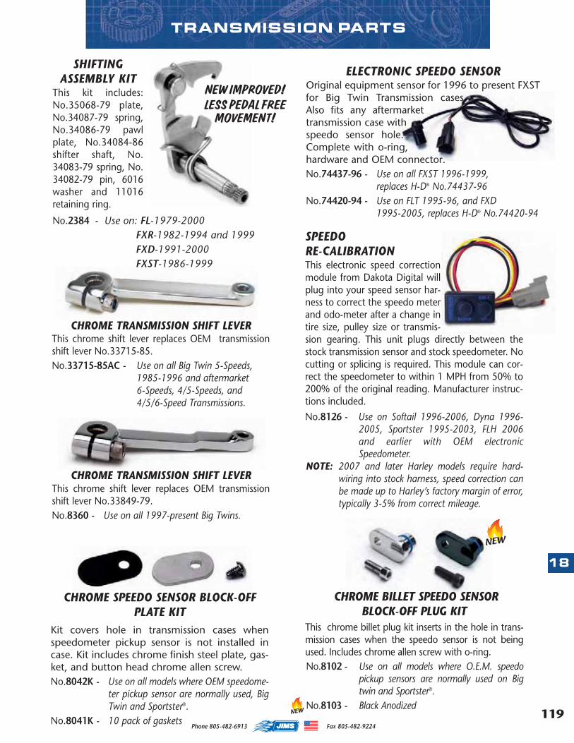
119
18
Phone 805-482-6913 Fax 805-482-9224
CHROME TRANSMISSION SHIFT LEVERThis chrome shift lever replaces OEM transmissionshift lever No.33715-85.No.33715-85AC - Use on all Big Twin 5-Speeds,
1985-1996 and aftermarket6-Speeds, 4/5-Speeds, and4/5/6-Speed Transmissions.
CHROME TRANSMISSION SHIFT LEVERThis chrome shift lever replaces OEM transmissionshift lever No.33849-79.No.8360 - Use on all 1997-present Big Twins.
SHIFTINGASSEMBLY KIT
This kit includes:No.35068-79 plate,No.34087-79 spring,No.34086-79 pawlplate, No.34084-86shifter shaft, No.34083-79 spring, No.34082-79 pin, 6016washer and 11016retaining ring.
No.2384 - Use on: FL-1979-2000FXR-1982-1994 and 1999FXD-1991-2000FXST-1986-1999
TRANSMISSION PARTS
CHROME SPEEDO SENSOR BLOCK-OFFPLATE KIT
Kit covers hole in transmission cases whenspeedometer pickup sensor is not installed incase. Kit includes chrome finish steel plate, gas-ket, and button head chrome allen screw.No.8042K - Use on all models where OEM speedome-
ter pickup sensor are normally used, BigTwin and Sportster®.
No.8041K - 10 pack of gaskets
SPEEDORE-CALIBRATIONThis electronic speed correctionmodule from Dakota Digital willplug into your speed sensor har-ness to correct the speedo meterand odo-meter after a change intire size, pulley size or transmis-sion gearing. This unit plugs directly between thestock transmission sensor and stock speedometer. Nocutting or splicing is required. This module can cor-rect the speedometer to within 1 MPH from 50% to200% of the original reading. Manufacturer instruc-tions included.
No.8126 - Use on Softail 1996-2006, Dyna 1996-2005, Sportster 1995-2003, FLH 2006and earlier with OEM electronicSpeedometer.
NOTE: 2007 and later Harley models require hard-wiring into stock harness, speed correction canbe made up to Harley’s factory margin of error,typically 3-5% from correct mileage.
CHROME BILLET SPEEDO SENSORBLOCK-OFF PLUG KIT
This chrome billet plug kit inserts in the hole in trans-mission cases when the speedo sensor is not beingused. Includes chrome allen screw with o-ring. No.8102 - Use on all models where O.E.M. speedo
pickup sensors are normally used on Bigtwin and Sportster®.
No.8103 - Black Anodized
NEW IMPROVED!LESS PEDAL FREE
MOVEMENT!
ELECTRONIC SPEEDO SENSOROriginal equipment sensor for 1996 to present FXSTfor Big Twin Transmission cases.Also fits any aftermarkettransmission case withspeedo sensor hole.Complete with o-ring,hardware and OEM connector.No.74437-96 - Use on all FXST 1996-1999,
replaces H-D® No.74437-96 No.74420-94 - Use on FLT 1995-96, and FXD
1995-2005, replaces H-D® No.74420-94
NEW
NEW
MASTER 2013 CATALOG_JMS 2.qxp:Layout 1 8/2/12 8:27 PM Page 119
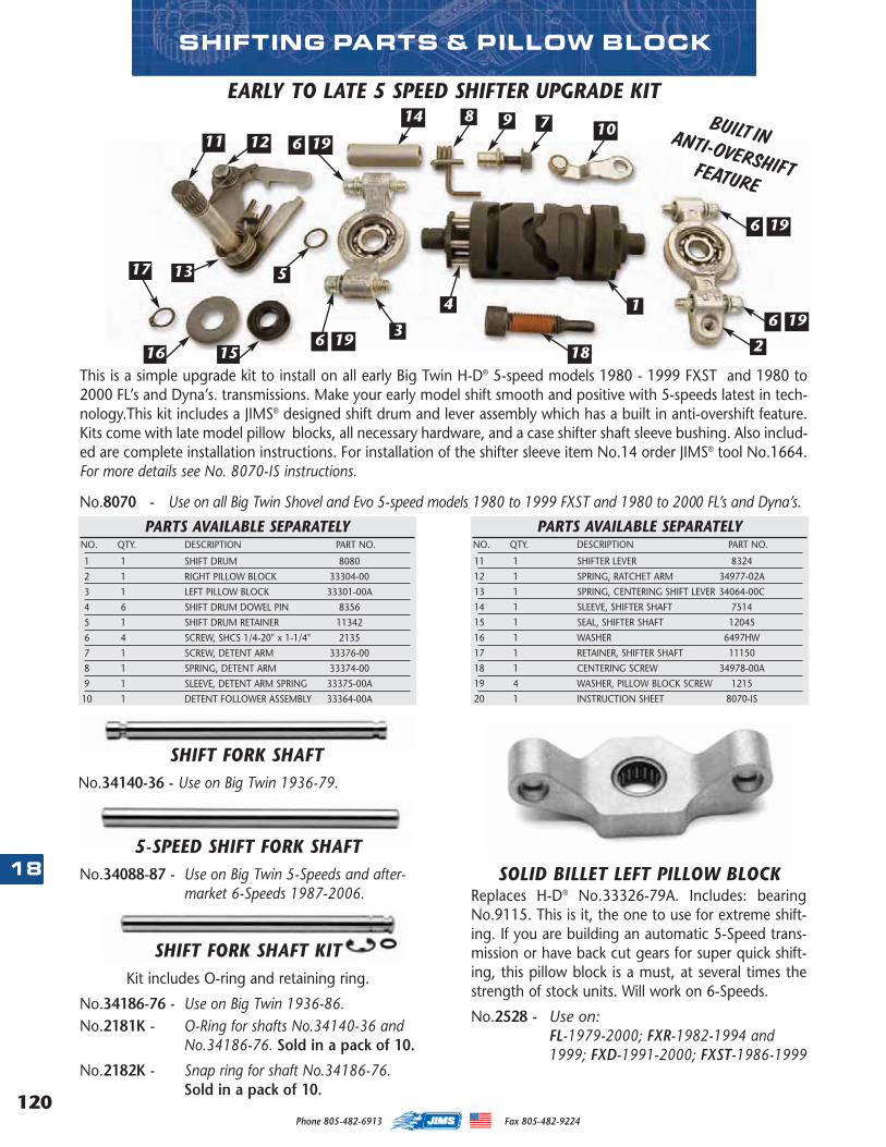
120
18
Phone 805-482-6913 Fax 805-482-9224
SOLID BILLET LEFT PILLOW BLOCKReplaces H-D® No.33326-79A. Includes: bearingNo.9115. This is it, the one to use for extreme shift-ing. If you are building an automatic 5-Speed trans-mission or have back cut gears for super quick shift-ing, this pillow block is a must, at several times thestrength of stock units. Will work on 6-Speeds.
No.2528 - Use on: FL-1979-2000; FXR-1982-1994 and 1999; FXD-1991-2000; FXST-1986-1999
SHIFTING PARTS & PILLOW BLOCK
2
1
7
4
98
6
5
3
1211 19
6 19
17
16 15
13
6 19
6 19
10
18
14
This is a simple upgrade kit to install on all early Big Twin H-D® 5-speed models 1980 - 1999 FXST and 1980 to200 0 FL’s and Dyna’s. transmissions. Make your early model shift smooth and positive with 5-speeds latest in tech-nology.This kit includes a JIMS® designed shift drum and lever assembly which has a built in anti-overshift feature.Kits come with late model pillow blocks, all necessary hardware, and a case shifter shaft sleeve bushing. Also includ-ed are complete installation instructions. For installation of the shifter sleeve item No.14 order JIMS® tool No.1664.For more details see No. 8070-IS instructions.
No.8070 - Use on all Big Twin Shovel and Evo 5-speed models 1980 to 1999 FXST and 1980 to 200 0 FL’s and Dyna’s.
PARTS AVAILABLE SEPARATELYNO. QTY. DESCRIPTION PART NO.
1 1 SHIFT DRUM 8080
2 1 RIGHT PILLOW BLOCK 33304-00
3 1 LEFT PILLOW BLOCK 33301-00A
4 6 SHIFT DRUM DOWEL PIN 8356
5 1 SHIFT DRUM RETAINER 11342
6 4 SCREW, SHCS 1/4-20" x 1-1/4" 2135
7 1 SCREW, DETENT ARM 33376-00
8 1 SPRING, DETENT ARM 33374-00
9 1 SLEEVE, DETENT ARM SPRING 33375-00A
10 1 DETENT FOLLOWER ASSEMBLY 33364-00A
PARTS AVAILABLE SEPARATELYNO. QTY. DESCRIPTION PART NO.
11 1 SHIFTER LEVER 8324
12 1 SPRING, RATCHET ARM 34977-02A
13 1 SPRING, CENTERING SHIFT LEVER 34064-00C
14 1 SLEEVE, SHIFTER SHAFT 7514
15 1 SEAL, SHIFTER SHAFT 12045
16 1 WASHER 6497HW
17 1 RETAINER, SHIFTER SHAFT 11150
18 1 CENTERING SCREW 34978-00A
19 4 WASHER, PILLOW BLOCK SCREW 1215
20 1 INSTRUCTION SHEET 8070-IS
EARLY TO LATE 5 SPEED SHIFTER UPGRADE KIT
SHIFT FORK SHAFT KITKit includes O-ring and retaining ring.
No.34186-76 - Use on Big Twin 1936-86.No.2181K - O-Ring for shafts No.34140-36 and
No.34186-76. Sold in a pack of 10.
No.2182K - Snap ring for shaft No.34186-76.Sold in a pack of 10.
5-SPEED SHIFT FORK SHAFTNo.34088-87 - Use on Big Twin 5-Speeds and after-
market 6-Speeds 1987-2006.
SHIFT FORK SHAFTNo.34140-36 - Use on Big Twin 1936-79.
BUILT INANTI-OVERSHIFTFEATURE
MASTER 2013 CATALOG_JMS 2.qxp:Layout 1 8/2/12 8:27 PM Page 120
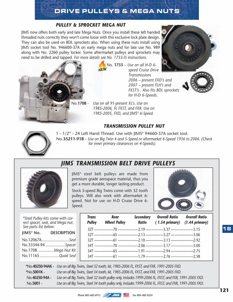
121
18
Phone 805-482-6913 Fax 805-482-9224
NEW
DRIVE PULLEYS & MEGA NUTS
JIMS®
TRANSMISSION BELT DRIVE PULLEYS
JIMS® steel belt pulleys are made frompremium grade aerospace material, thus youget a more durable, longer lasting product.
Stock 5-speed Big Twins come with 32 toothpulleys. Will also work with aftermarket 6-speed. Not for use on H-D Cruise Drive 6-Speed.
No.1708 - Use on all 91-present XL’s. Use on1985-2006, FL FXST, and FXR. Use on1985-2005, FXD, and JIMS® 6-Speed.
TRANSMISSION PULLEY NUT1 - 1/2” - 24 Left Hand Thread. Use with JIMS® 94660-37A socket tool.No.35211-91B - Use on Big Twin 4 and 5-Speed or aftermarket 6-Speed 1936 to 2006. (Check
for inner primary clearances on 4-Speeds).
*Steel Pulley kits come with cor-rect spacer, seal, and Mega nut.See parts list below: JIMS® No. DESCRIPTION
No.12067A .........................SealNo.33344-94 ..................SpacerNo.1708 ...............Mega Nut KitNo.11165..................Quad Seal
PULLEY & SPROCKET MEGA NUTJIMS now offers both early and late Mega Nuts. Once you install these left handedthreaded nuts correctly they won’t come loose with this exclusive lock plate design.They can also be used on BDL sprockets also. When using these nuts install usingJIMS socket tool No. 946600-37A on early mega nuts and for late use No. 989along with No. 2260 pulley locker. Some aftermarket pulleys and sprockets mayneed to be drilled and tapped. For more details see No. 1733-IS instructions.
Trans Rear Secondary Overall Ratio Overall RatioPulley Wheel Pulley Ratio ( 1.54 primary) (1.44 primary)
32T -----------------70 ------------------2.19 ----------------3.37 --------------------3.1532T -----------------65 ------------------2.13 ----------------3.27 --------------------3.0632T -----------------61 ------------------2.10 ----------------3.13 --------------------2.9234T -----------------70 ------------------2.06 ----------------3.17 --------------------3.0034T -----------------65 ------------------1.91 ----------------2.94 --------------------2.7534T -----------------61 ------------------1.79 ----------------2.76 --------------------2.58
*No.40250-94AK - Use on all Big Twins, Steel 32 tooth, kit, 1985-2006 FL, FXST, and FXR, 1991-2005 FXD.*No.5001K - Use on all Big Twins, Steel 34 tooth, kit, 1985-2006 FL, FXST, and FXR, 1991-2005 FXD.No.40250-94A - Use on all Big Twins, Steel 32 tooth pulley only, Includes 1999-2006 FL, FXST, and FXR, 1991-2005 FXD.No.5001 - Use on all Big Twins, Steel 34 tooth pulley only, Includes 1999-2006 FL, FXST, and FXR, 1991-2005 FXD.
No. 1733 – Use on all H-D 6-speed Cruise DriveTransmissions2006 – present FXD’s and2007 – present FLH’s andFXST’s . Also fits BDL sprocketsfor H-D 6-Speeds.
MASTER 2013 CATALOG_JMS 2.qxp:Layout 1 8/2/12 8:27 PM Page 121
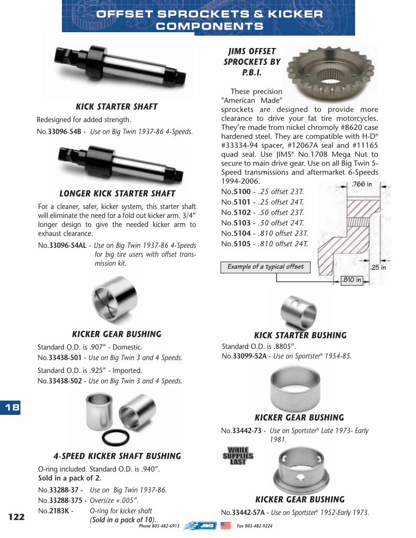
122
18
Phone 805-482-6913 Fax 805-482-9224
KICK STARTER SHAFTRedesigned for added strength.
No.33096-54B - Use on Big Twin 1937-86 4-Speeds.
KICKER GEAR BUSHINGNo.33442-73 - Use on Sportster® Late 1973- Early
1981.
4-SPEED KICKER SHAFT BUSHINGO-ring included. Standard O.D. is .940”. Sold in a pack of 2.
No.33288-37 - Use on Big Twin 1937-86. No.33288-375 - Oversize +.005”.No.2183K - O-ring for kicker shaft
(Sold in a pack of 10).
KICKER GEAR BUSHINGNo.33442-57A - Use on Sportster® 1952-Early 1973.
OFFSET SPROCKETS & KICKERCOMPONENTS
KICKER GEAR BUSHINGStandard O.D. is .907” - Domestic.No.33438-501 - Use on Big Twin 3 and 4 Speeds.
Standard O.D. is .925” - Imported.No.33438-502 - Use on Big Twin 3 and 4 Speeds.
KICK STARTER BUSHINGStandard O.D. is .8805”.No.33099-52A - Use on Sportster® 1954-85.
LONGER KICK STARTER SHAFTFor a cleaner, safer, kicker system, this starter shaftwill eliminate the need for a fold out kicker arm. 3/4”longer design to give the needed kicker arm toexhaust clearance.
No.33096-54AL - Use on Big Twin 1937-86 4-Speedsfor big tire users with offset trans-mission kit.
JIMS OFFSETSPROCKETS BY
P.B.I.
These precision"American Made"sprockets are designed to provide moreclearance to drive your fat tire motorcycles.They’re made from nickel chromoly #8620 casehardened steel. They are compatible with H-D®
#33334-94 spacer, #12067A seal and #11165quad seal. Use JIMS® No.1708 Mega Nut tosecure to main drive gear. Use on all Big Twin 5-Speed transmissions and aftermarket 6-Speeds1994-2006.No.5100 - .25 offset 23T.No.5101 - .25 offset 24T.No.5102 - .50 offset 23T.No.5103 - .50 offset 24T.No.5104 - .810 offset 23T.No.5105 - .810 offset 24T.
.766 in
.25 in
.810 in
Example of a typical offset
MASTER 2013 CATALOG_JMS 2.qxp:Layout 1 8/2/12 8:28 PM Page 122
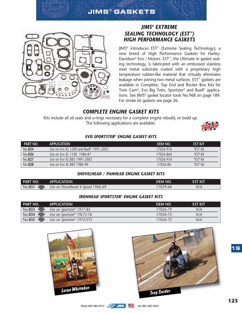
123
19
Phone 805-482-6913 Fax 805-482-9224
JIMS® EXTREME SEALING TECHNOLOGY (EST™)HIGH PERFORMANCE GASKETS
COMPLETE ENGINE GASKET KITSKits include all oil seals and o-rings necessary for a complete engine rebuild, or build up.
The following applications are available:
JIMS® introduces EST™ (Extreme Sealing Technology), anew breed of High Performance Gaskets for Harley-Davidson® Evo / Motors. EST™, the Ultimate in gasket seal-ing technology, is fabricated with an embossed stainlesssteel metal substrate coated with a proprietary hightemperature rubber-like material that virtually eliminatesleakage when joining two metal surfaces. EST™ gaskets areavailable in Complete, Top End and Rocker Box Kits forTwin Cam®, Evo Big Twin, Sportster® and Buell® applica-tions. See JIMS® gasket locator tools No.968 on page 189.For stroke kit gaskets see page 26.
PART NO. APPLICATION OEM NO. EST KITNo.824 Use on Evo XL 1200 and Buell® 1991-2003 17026-91A *EST KitNo.826 Use on Evo XL 1100 1986-87 17026-86A *EST KitNo.827 Use on Evo XL 883 1991-2003 17026-91A *EST KitNo.828 Use on Evo XL 883 1986-90 17026-86 *EST Kit
PART NO. APPLICATION OEM NO. EST KITNo.831 Use on Shovelhead 4-Speed 1966-69 17029-66 N/A
PART NO. APPLICATION OEM NO. EST KITNo.833 Use on Sportster® 1977-85 17026-79 N/ANo.834 Use on Sportster® 19L73-76 17026-73 N/ANo.835 Use on Sportster® 1972-E73 17026-72 N/A
EVO SPORTSTER® ENGINE GASKET KITS
SHOVELHEAD / PANHEAD ENGINE GASKET KITS
IRONHEAD SPORTSTER® ENGINE GASKET KITS
JIMS ® GASKETS
Loran WhittakerTroy Snider
MASTER 2013 CATALOG_JMS 2.qxp:Layout 1 8/2/12 8:28 PM Page 123
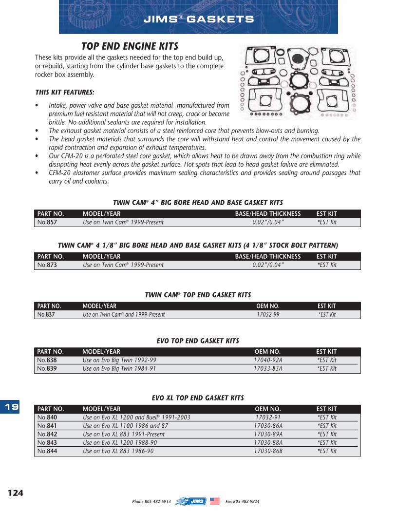
124
19
Phone 805-482-6913 Fax 805-482-9224
• Intake, power valve and base gasket material manufactured frompremium fuel resistant material that will not creep, crack or becomebrittle. No additional sealants are required for installation.
• The exhaust gasket material consists of a steel reinforced core that prevents blow-outs and burning. • The head gasket materials that surrounds the core will withstand heat and control the movement caused by the
rapid contraction and expansion of exhaust temperatures. • Our CFM-20 is a perforated steel core gasket, which allows heat to be drawn away from the combustion ring while
dissipating heat evenly across the gasket surface. Hot spots that lead to head gasket failure are eliminated. • CFM-20 elastomer surface provides maximum sealing characteristics and provides sealing around passages that
carry oil and coolants.
TOP END ENGINE KITSThese kits provide all the gaskets needed for the top end build up,or rebuild, starting from the cylinder base gaskets to the completerocker box assembly.
THIS KIT FEATURES:
PART NO. MODEL/YEAR OEM NO. EST KITNo.837 Use on Twin Cam® and 1999-Present 17052-99 *EST Kit
PART NO. MODEL/YEAR OEM NO. EST KITNo.838 Use on Evo Big Twin 1992-99 17040-92A *EST KitNo.839 Use on Evo Big Twin 1984-91 17033-83A *EST Kit
PART NO. MODEL/YEAR OEM NO. EST KITNo.840 Use on Evo XL 1200 and Buell® 1991-2003 17032-91 *EST KitNo.841 Use on Evo XL 1100 1986 and 87 17030-86A *EST KitNo.842 Use on Evo XL 883 1991-Present 17030-89A *EST KitNo.843 Use on Evo XL 1200 1988-90 17030-88A *EST KitNo.844 Use on Evo XL 883 1986-90 17030-86B *EST Kit
TWIN CAM® TOP END GASKET KITS
EVO TOP END GASKET KITS
EVO XL TOP END GASKET KITS
PART NO. MODEL/YEAR BASE/HEAD THICKNESS EST KITNo.857 Use on Twin Cam® 1999-Present 0.02”/0.04” *EST Kit
TWIN CAM® 4” BIG BORE HEAD AND BASE GASKET KITS
JIMS ® GASKETS
PART NO. MODEL/YEAR BASE/HEAD THICKNESS EST KITNo.873 Use on Twin Cam® 1999-Present 0.02”/0.04” *EST Kit
TWIN CAM® 4 1/8” BIG BORE HEAD AND BASE GASKET KITS (4 1/8” STOCK BOLT PATTERN)
MASTER 2013 CATALOG_JMS 2.qxp:Layout 1 8/2/12 8:28 PM Page 124
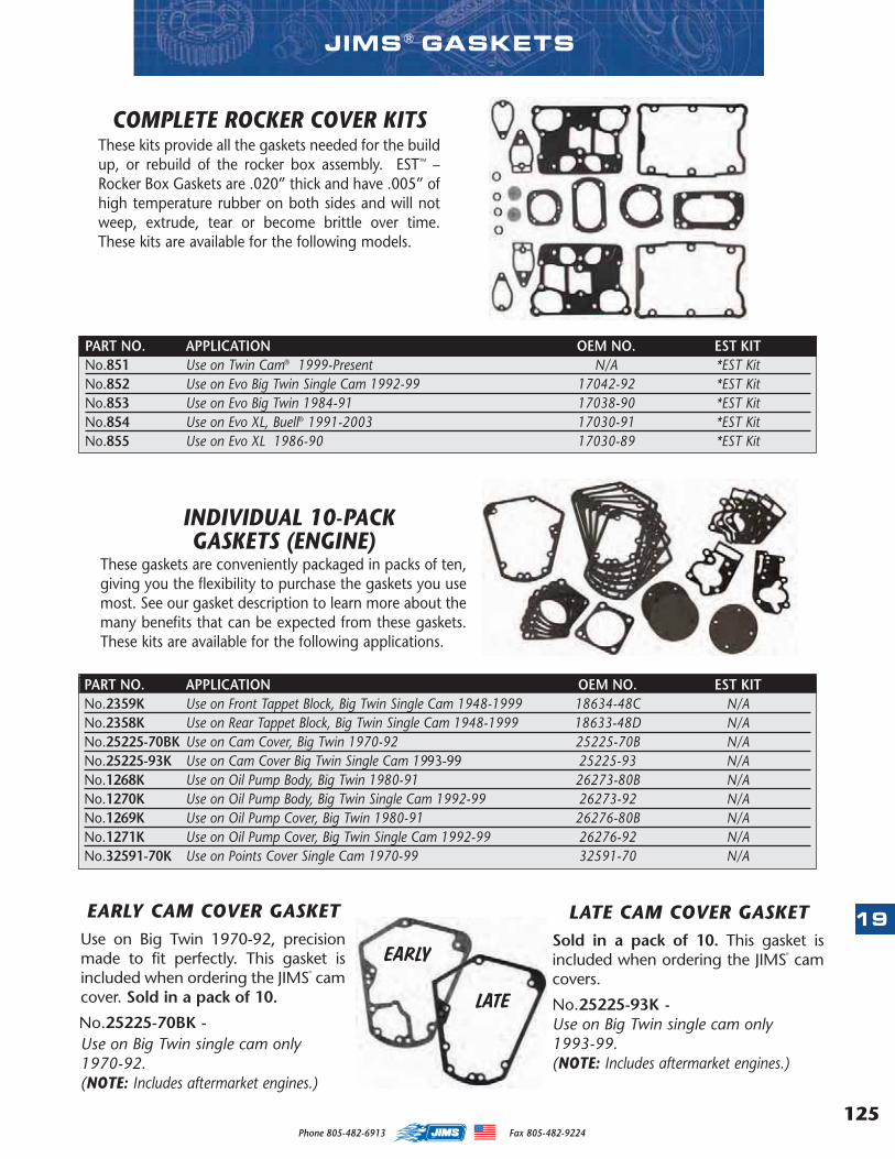
125
19
Phone 805-482-6913 Fax 805-482-9224
INDIVIDUAL 10-PACKGASKETS (ENGINE)
These gaskets are conveniently packaged in packs of ten,giving you the flexibility to purchase the gaskets you usemost. See our gasket description to learn more about themany benefits that can be expected from these gaskets.These kits are available for the following applications.
COMPLETE ROCKER COVER KITSThese kits provide all the gaskets needed for the buildup, or rebuild of the rocker box assembly. EST™ –Rocker Box Gaskets are .020” thick and have .005” ofhigh temperature rubber on both sides and will notweep, extrude, tear or become brittle over time.These kits are available for the following models.
PART NO. APPLICATION OEM NO. EST KITNo.851 Use on Twin Cam® 1999-Present N/A *EST KitNo.852 Use on Evo Big Twin Single Cam 1992-99 17042-92 *EST KitNo.853 Use on Evo Big Twin 1984-91 17038-90 *EST KitNo.854 Use on Evo XL, Buell® 1991-2003 17030-91 *EST KitNo.855 Use on Evo XL 1986-90 17030-89 *EST Kit
PART NO. APPLICATION OEM NO. EST KITNo.2359K Use on Front Tappet Block, Big Twin Single Cam 1948-1999 18634-48C N/ANo.2358K Use on Rear Tappet Block, Big Twin Single Cam 1948-1999 18633-48D N/ANo.25225-70BK Use on Cam Cover, Big Twin 1970-92 25225-70B N/ANo.25225-93K Use on Cam Cover Big Twin Single Cam 1993-99 25225-93 N/ANo.1268K Use on Oil Pump Body, Big Twin 1980-91 26273-80B N/ANo.1270K Use on Oil Pump Body, Big Twin Single Cam 1992-99 26273-92 N/ANo.1269K Use on Oil Pump Cover, Big Twin 1980-91 26276-80B N/ANo.1271K Use on Oil Pump Cover, Big Twin Single Cam 1992-99 26276-92 N/ANo.32591-70K Use on Points Cover Single Cam 1970-99 32591-70 N/A
EARLY CAM COVER GASKETUse on Big Twin 1970-92, precisionmade to fit perfectly. This gasket isincluded when ordering the JIMS
®
camcover. Sold in a pack of 10.
No.25225-70BK -
LATE CAM COVER GASKETSold in a pack of 10. This gasket isincluded when ordering the JIMS
®
camcovers.
No.25225-93K -Use on Big Twin single cam only1993-99.(NOTE: Includes aftermarket engines.)
LATE
EARLY
Use on Big Twin single cam only1970-92.(NOTE: Includes aftermarket engines.)
JIMS ® GASKETS
MASTER 2013 CATALOG_JMS 2.qxp:Layout 1 8/2/12 8:28 PM Page 125
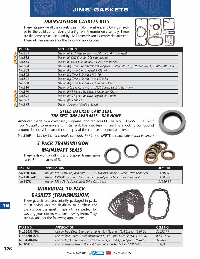
126
19
Phone 805-482-6913 Fax 805-482-9224
INDIVIDUAL 10-PACKGASKETS (TRANSMISSION)
These gaskets are conveniently packaged in packsof 10 giving you the flexibility to purchase thegaskets you use most. These kits are perfect forstocking your shelves with fast moving items. Theyare available for the following applications:
PART NO. APPLICATION OEM NO.No.35652-79K Use on Trap Door, 5 and aftermarket 6, 4/5, and 4/5/6 Speed 1980-06 35652-79No.36801-87K Use on Side Cover, 5 and aftermarket 6, 4/5, and 4/5/6 Speed 1987-06 36801-87ANo.34904-86K Use on Top Cover, 5 and aftermarket 6, 4/5, and 4/5/6 Speed 1986-99 34904-86No.8041K Use on Speedo Sensor Block-off 5 and aftermarket 6-Speed 1995-06 N/A
5-PACK TRANSMISSION MAINSHAFT SEALS
These seals work on all 4, 5 and 6-Speed transmissioncases. Sold in packs of 5.
PART NO. APPLICATION OEM NO.
No.12013AK Use on 1965-early 66, and Late 1981-86 Big Twin Models - Main Drive Gear Seal 12013ANo.12035AK Use on 1991-06 Big Twin, 5 or aftermarket 6-Speed - Main Drive Gear Seal 12035ANo.817K Use on 1936-79 (4-Speed Main Drive Case Seal) 35230-39
JIMS ® GASKETS
STEEL BACKED CAM SEALTHE BEST ONE AVAILABLE - BAR NONE
American made cam cover seal, surpasses and replaces O.E.M. No.83162-51. Use JIMS®
Tool No.2243 to remove and install seal. For a no leak fit, seal has a locking compoundaround the outside diameter to help seal the cam seal to the cam cover.
No.2169 - Use on Big Twin single cam only 1970- 99. (NOTE: Includes aftermarket engines.)
PART NO. APPLICATION . 804 Use on Big Twin 5 or 6-Speed 1999-PresentNo.881 Use on all FLH 6-sp Touring models for 2007 to presentNo.882 Use on all FXD 6-sp for 2006 to presentNo.883 Use on all FXST 6-sp models for 2007 to presentNo.804 Use on Big Twin 5 or aftermarket 6-Speed 1999-2005 FXD, 1999-2006 FL, 2000-2006 FXSTNo.803 Use on Big Twin 5 or 6-Speed 1991-98No.802 Use on Big Twin 5-Speed 1980-90No.801 Use on Big Twin 4-Speed Late 1979-86No.800 Use on Big Twin 4-Speed 1936 to Early 1979No.816 Use on 5-Speed Case 4/5 or 4/5/6 Speed, Electric Start only.No.890 Use on JIMS Right Side Drive, Mechanical ClutchNo.891 Use on JIMS Right Side Drive, Hydraulic ClutchNo.892 Use on JIMS FAT - 5 No.893 Use on Screamin’ Eagle 6-Speed
NEW
NEW
NEW
TRANSMISSION GASKETS KITSThese kits provide all the gaskets, seals, nylon washers, and O-rings need-ed for the build up, or rebuild of a Big Twin transmission assembly. Theseare the same gasket kits used by JIMS
®
transmission assembly department.These kits are available for the following applications:
NEW
NEW
NEW
NEW
MASTER 2013 CATALOG_JMS 2.qxp:Layout 1 8/14/12 8:24 AM Page 126

127
1
2
3
4
5
6
7
8
9
10
12
13
14
15
16
17
18
19
20
11
22
23
24
25
26
27
28
29
21
Phone 805-482-6913 Fax 805-482-9224
JIMS ® TOOLS
127
MINI VALVE
SPRING TESTER
No.1090
PISTON JET TEST
STANDNo.772
LIFT CADDY
No.776
O2 SENSOR
WRENCH
No.755
STEM NUT WRENCHNo.977
SLIM JIM
FILTER WRENCH
No.941
AFR SNIFFER
No.777
TOOLS
MASTER 2013 CATALOG_JMS 2.qxp:Layout 1 8/2/12 8:28 PM Page 127

128 Phone 805-482-6913 Fax 805-482-9224128
JIMS is at the forefront of designing and manufacturing speciality tools for use onHarley-Davidson® Motorcycles. For many years, JIMS has offered tool solutions tomake your work easier, faster and safer. The JIMS R&D department prides them-selves on creative thinking, when it comes to tool design - and our manufacturingfacility backs that up with tools that are warranted for life.
What happens when you, the end mechanic, have a great idea for a tool but, havenowhere to go... Look no further, introducing the tool submission program. Oftentimes, we have people like you, who want to bring ideas to JIMS - but are unsureof what the process and or compensations are. We figured we'd put it in black andwhite. If your looking to get rich quick from a tool idea, than this process is notfor you. If you simply want to present an idea, and possibly see it in the JIMS cat-alog - it doesn't get any easier than this...
Put together your ideas by whatever means you have, be it - drawing sketches,writing a detailed description of how the tool works and why it's valuable, sendprototypes, etc... Send these ideas to:
TTool Submission ProgramJIMS R&D Department
555 Dawson DriveCamarillo, CA 93012
By doing this, you are authorizing JIMS to evaluate designing and or adding yourtool to the JIMS product line. If your tool is selected for a JIMS new product, youwill receive 1 of the tools free, after it is processed through production, along with$250 towards JIMS parts and tools - along with a catalog mention of you as theinventor in the description of the tool in the JIMS catalog.
THE JIMS TOOL SUBMISSION PROGRAM
CREATING THE TOOLS DESIGNED BY YOU, THE V-TWIN MECHANIC.
THE JIMS® TOOL SUBMISSION PROGRAM
TOOLS THROUGH
SUBMISSION!
TRANS SLEEVE INSTALLER &
REMOVER No. 1658
B MOTOR SUPPORT BLOCKS
No. 916
FORK STEM WRENCH
No. 977
MASTER 2013 CATALOG_JMS 2.qxp:Layout 1 8/2/12 8:29 PM Page 128
129
1
2
3
4
5
6
7
8
9
10
12
13
14
15
16
17
18
19
20
11
22
23
24
25
26
21
Phone 805-482-6913 Fax 805-482-9224
NEW TOOL QUICK REFERENCE SECTION TABS PAGE
ACCELERATOR SOFTWARE TOOL . . . . . . . . . . . . . . . . . . . . . . . . . . . . . . . . . . . . . . . . . . . . . . .
TAPPET PUMP UP & PISTON JET TEST STAND TOOLS . . . . . . . . . . . . . . . . . . . . . .
LIFT CADDY & VALVE SPRING TESTER TOOL . . . . . . . . . . . . . . . . . . . . . . . . . . . . . . . . . .
TIMKEN TOOL TOOLS . . . . . . . . . . . . . . . . . . . . . . . . . . . . . . . . . . . . . . . . . . . . . . . . . . . . . . . . . . . . . .
FUEL INJECTION TOOLS . . . . . . . . . . . . . . . . . . . . . . . . . . . . . . . . . . . . . . . . . . . . . . . . . . . . . . . . . . .
DIAGNOSTIC TOOLS . . . . . . . . . . . . . . . . . . . . . . . . . . . . . . . . . . . . . . . . . . . . . . . . . . . . . . . . . . . . . . . .
IGNITION , FUEL PUMP, & ELECTRICAL TOOLS . . . . . . . . . . . . . . . . . . . . . . . . . . . . . . . .
VALVE TRAIN TOOLS . . . . . . . . . . . . . . . . . . . . . . . . . . . . . . . . . . . . . . . . . . . . . . . . . . . . . . . . . . . . . . . .
CAM TOOLS . . . . . . . . . . . . . . . . . . . . . . . . . . . . . . . . . . . . . . . . . . . . . . . . . . . . . . . . . . . . . . . . . . . . . . . . . .
TAPPET BLOCK & ROD TOOLS . . . . . . . . . . . . . . . . . . . . . . . . . . . . . . . . . . . . . . . . . . . . . . . . . . .
WRIST PIN & PISTON TOOLS . . . . . . . . . . . . . . . . . . . . . . . . . . . . . . . . . . . . . . . . . . . . . . . . . . . . . .
CYLINDER TOOLS . . . . . . . . . . . . . . . . . . . . . . . . . . . . . . . . . . . . . . . . . . . . . . . . . . . . . . . . . . . . . . . . . .
CASE BORING & LAPPING TOOLS . . . . . . . . . . . . . . . . . . . . . . . . . . . . . . . . . . . . . . . . . . . . . . .
TWIN CAM BALANCER TOOLS . . . . . . . . . . . . . . . . . . . . . . . . . . . . . . . . . . . . . . . . . . . . . . . . . . .
FLYWHEEL & CRANKSHAFT BEARING TOOLS . . . . . . . . . . . . . . . . . . . . . . . . . . . . . . . .
LEFT CASE TOOLS . . . . . . . . . . . . . . . . . . . . . . . . . . . . . . . . . . . . . . . . . . . . . . . . . . . . . . . . . . . . . . . . . .
PINION GEAR TOOLS . . . . . . . . . . . . . . . . . . . . . . . . . . . . . . . . . . . . . . . . . . . . . . . . . . . . . . . . . . . . . . .
OIL PUMP, FILTERS, & ENGINE DIPSTICK TOOLS . . . . . . . . . . . . . . . . . . . . . . . . . . . . . .
CLUTCH & PRIMARY DRIVE TOOLS . . . . . . . . . . . . . . . . . . . . . . . . . . . . . . . . . . . . . . . . . . . . .
PULLEY & TRANSMISSION TOOLS . . . . . . . . . . . . . . . . . . . . . . . . . . . . . . . . . . . . . . . . . . . . . .
FORK, NECK, & FRAME TOOLS . . . . . . . . . . . . . . . . . . . . . . . . . . . . . . . . . . . . . . . . . . . . . . . . . . .
AXLE, CHAIN, BELT, WHEEL, BRAKE, STAND & JACK TOOLS . . . . . . . . . . . . . . .
ENGINE PLUG KIT . . . . . . . . . . . . . . . . . . . . . . . . . . . . . . . . . . . . . . . . . . . . . . . . . . . . . . . . . . . . . . . . . . .
GENERAL TOOLS & MANUALS . . . . . . . . . . . . . . . . . . . . . . . . . . . . . . . . . . . . . . . . . . . . . . . . . . .
CHEMICALS, LUBRICANTS, & SUPPLYS . . . . . . . . . . . . . . . . . . . . . . . . . . . . . . . . . . . . . . . .
CLOTHING . . . . . . . . . . . . . . . . . . . . . . . . . . . . . . . . . . . . . . . . . . . . . . . . . . . . . . . . . . . . . . . . . . . . . . . . . . . .
MASTER 2013 CATALOG_JMS 2.qxp:Layout 1 8/2/12 8:29 PM Page 129
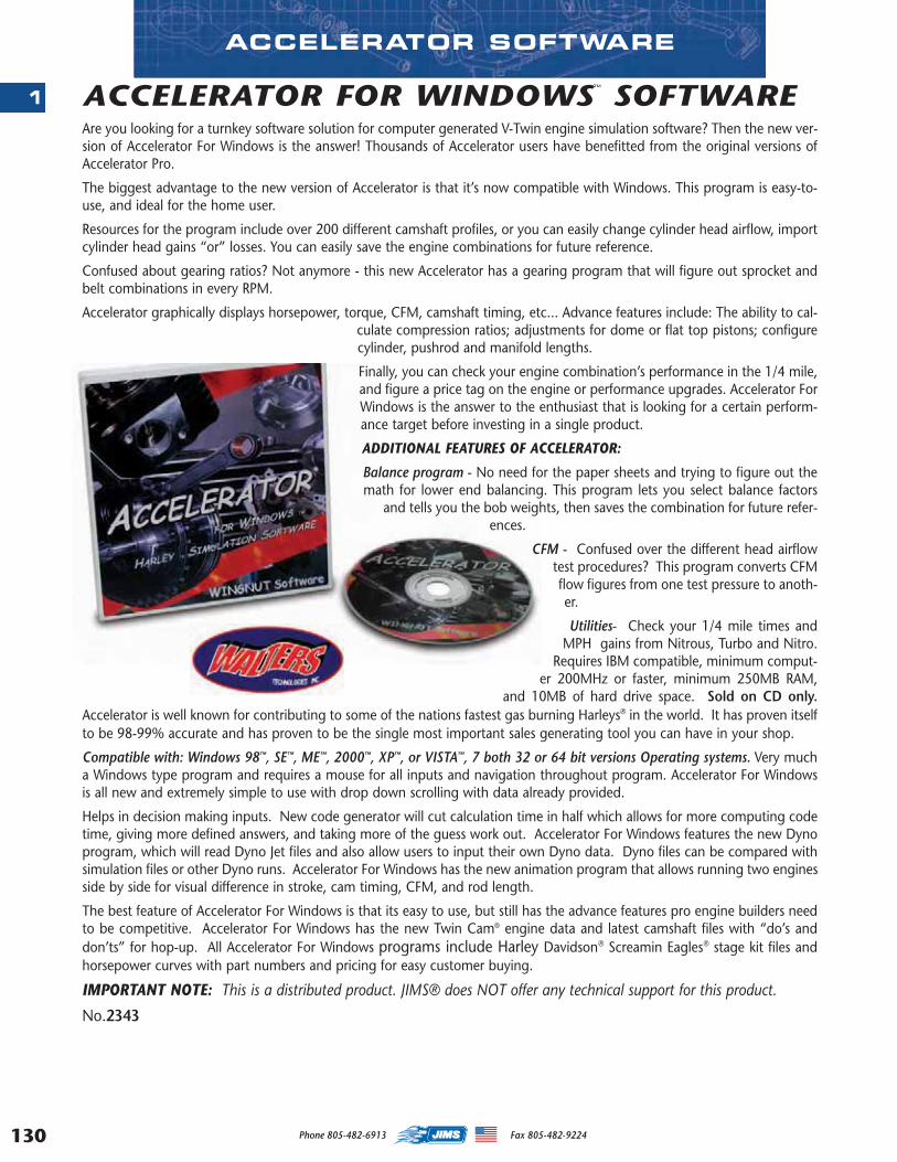
130
1
Phone 805-482-6913 Fax 805-482-9224
ACCELERATOR FOR WINDOWS™ SOFTWAREAre you looking for a turnkey software solution for computer generated V-Twin engine simulation software? Then the new ver-sion of Accelerator For Windows is the answer! Thousands of Accelerator users have benefitted from the original versions ofAccelerator Pro.
The biggest advantage to the new version of Accelerator is that it’s now compatible with Windows. This program is easy-to-use, and ideal for the home user.
Resources for the program include over 200 different camshaft profiles, or you can easily change cylinder head airflow, importcylinder head gains “or” losses. You can easily save the engine combinations for future reference.
Confused about gearing ratios? Not anymore - this new Accelerator has a gearing program that will figure out sprocket andbelt combinations in every RPM.
Accelerator graphically displays horsepower, torque, CFM, camshaft timing, etc... Advance features include: The ability to cal-culate compression ratios; adjustments for dome or flat top pistons; configurecylinder, pushrod and manifold lengths.
Finally, you can check your engine combination’s performance in the 1/4 mile,and figure a price tag on the engine or performance upgrades. Accelerator ForWindows is the answer to the enthusiast that is looking for a certain perform-ance target before investing in a single product.
ADDITIONAL FEATURES OF ACCELERATOR:
Balance program - No need for the paper sheets and trying to figure out themath for lower end balancing. This program lets you select balance factors
and tells you the bob weights, then saves the combination for future refer-ences.
CFM - Confused over the different head airflowtest procedures? This program converts CFMflow figures from one test pressure to anoth-er.
Utilities- Check your 1/4 mile times andMPH gains from Nitrous, Turbo and Nitro.
Requires IBM compatible, minimum comput-er 200MHz or faster, minimum 250MB RAM,
and 10MB of hard drive space. Sold on CD only.Accelerator is well known for contributing to some of the nations fastest gas burning Harleys® in the world. It has proven itselfto be 98-99% accurate and has proven to be the single most important sales generating tool you can have in your shop.
Compatible with: Windows 98™, SE™, ME™, 2000™, XP™, or VISTA™, 7 both 32 or 64 bit versions Operating systems. Very mucha Windows type program and requires a mouse for all inputs and navigation throughout program. Accelerator For Windowsis all new and extremely simple to use with drop down scrolling with data already provided.
Helps in decision making inputs. New code generator will cut calculation time in half which allows for more computing codetime, giving more defined answers, and taking more of the guess work out. Accelerator For Windows features the new Dynoprogram, which will read Dyno Jet files and also allow users to input their own Dyno data. Dyno files can be compared withsimulation files or other Dyno runs. Accelerator For Windows has the new animation program that allows running two enginesside by side for visual difference in stroke, cam timing, CFM, and rod length.
The best feature of Accelerator For Windows is that its easy to use, but still has the advance features pro engine builders needto be competitive. Accelerator For Windows has the new Twin Cam® engine data and latest camshaft files with “do’s anddon’ts” for hop-up. All Accelerator For Windows programs include Harley Davidson® Screamin Eagles® stage kit files andhorsepower curves with part numbers and pricing for easy customer buying.
IMPORTANT NOTE: This is a distributed product. JIMS® does NOT offer any technical support for this product.
No.2343
ACCELERATOR SOFTWARE
MASTER 2013 CATALOG_JMS 2.qxp:Layout 1 8/2/12 8:29 PM Page 130

131
2
Phone 805-482-6913 Fax 805-482-9224
TAPPET PUMP AND TEST STANDWith the new Tappet Pump and Test Stand you can now completely fill your standard size hydraulic tappets, phys-ically inspect them and with the help of a drill press, check for proper feel. By using pressurized oil, this uniquetool will allow you to fill the tappet with oil, while “feeling” the fitment of the hydraulic unit. You can easily diag-nose loose or “spongy” tappets that could eventually lead to bleed down issues, or “sticky” tappets that won’tpump up due to poor hydraulic unit fitment. Mechanics can now have the confidence of knowing tappets won’tstick or bleed down once installed. This tool is available for both Twin Cam (No. 765) and Evo (No. 766) applica-tions. The Twin-Cam model ships with everything you need, except the drill press. For standard size hydraulic Evotappets, install the sleeve No. 766 into the tool body and you’re ready to go. For more details see No.765-IS instruc-tions. No. 765 - For standard size Twin Cam tappets, H-D, or JIMS Powerglide, or
other aftermarket equivalent.No. 766 - Insert sleeve adapter to fit all standard size Evo tappets, H-D, or
JIMS Powerglide, or other aftermarket equivalent. Orderseparately.
4
3
1
4
2
PISTON JET TEST STANDEver wonder what that piston jet is doing deep inside yourcrankcase? If “stuck open” - possible sumping issues? If “stuckclosed” - increased operating temperatures? Only with JIMS canthe detail minded engine builder clear the jet of all assembly lubes,verify the PSI number the jet switches “on” and visualize the spraypattern. Better yet, do all of this before you seal the cases! You canperform the test by using regulated air over oil for real life accuracy& visual confirmation, or just air for easier clean up. If you plan to
rebuild more than two Twin Camengines and or lower ends - this
tool pays for itself! For moredetails see No.772-IS instructions.
No. 772 - Piston Jet Test Standfor 1999 to presentTwin Cam piston jets.
OPTIONALEVO SLEEVE
No.766
PISTON JET, & TAPPET TEST STAND
1
29
5
7
4
11
8
63
10
PARTS AVAILABLE SEPARATELYNO. QTY. DESCRIPTION PART NO.
1 1 MAIN BODY 772-1
2 1 REGULATOR W/GAUGE 772-2
3 1 PIPE NIPPLE 772-3
4 2 ALLEN PLUG 772-6
5 1 INSTRUCTION SHEET 772-IS
PARTS AVAILABLE SEPARATELYNO. QTY. DESCRIPTION PART NO.
1 1 MAIN BODY 765-1
2 1 TWIN CAM ADAPTER 765-2
3 1 TUBE FITTING 765-3
4 1 TUBE FITTING 765-4
5 1 BALL VALVE 765-5
6 1 NYLON TUBE 765-6
7 1 0-100 GAUGE 765-7
8 1 PRESSURE TANK 765-8
9 1 O-RING 765-9
10 1 PUMP-UP RAM 2400-1
11 1 ALLEN LOCK SCREW 1691-29
12 1 NUT 1218
13 1 INSTRUCTION SHEET 765-IS
14 1 EVO TAPPET ADAPTER (OPTIONAL) 766
NEW
NEW
12
MASTER 2013 CATALOG_JMS 2.qxp:Layout 1 8/2/12 8:29 PM Page 131
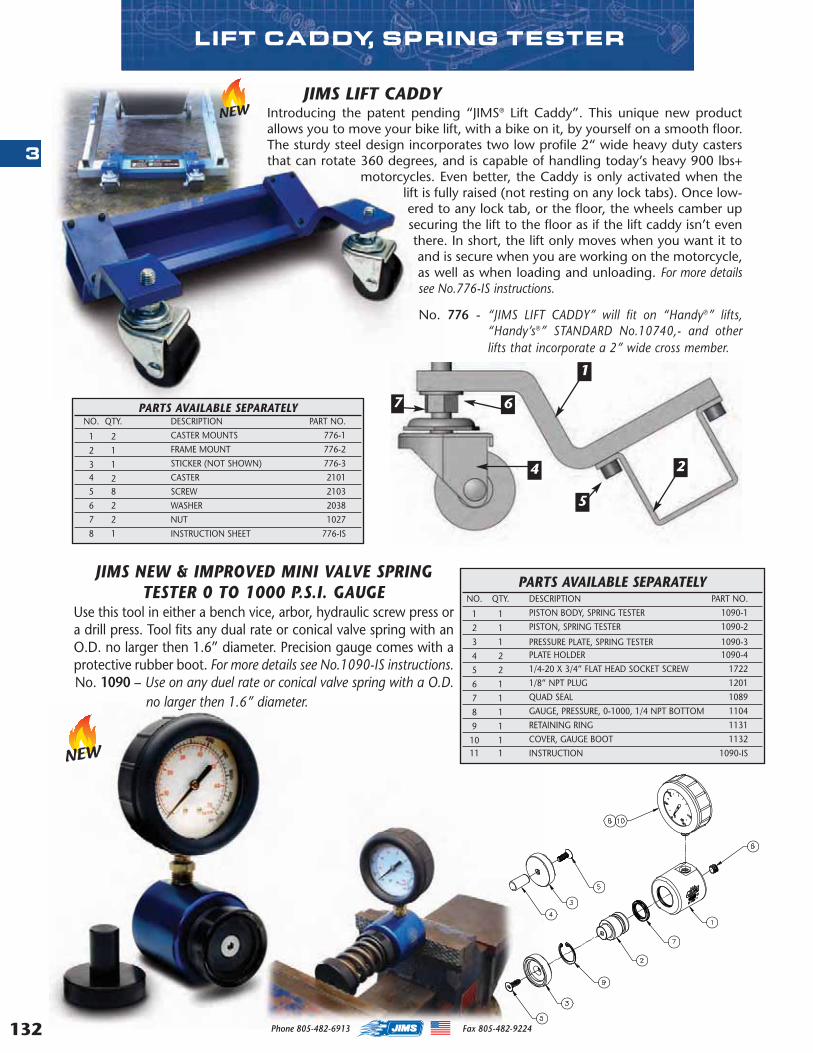
132
3
LIFT CADDY, SPRING TESTER
JIMS LIFT CADDYIntroducing the patent pending “JIMS® Lift Caddy”. This unique new productallows you to move your bike lift, with a bike on it, by yourself on a smooth floor.The sturdy steel design incorporates two low profile 2“ wide heavy duty castersthat can rotate 360 degrees, and is capable of handling today’s heavy 900 lbs+
motorcycles. Even better, the Caddy is only activated when thelift is fully raised (not resting on any lock tabs). Once low-ered to any lock tab, or the floor, the wheels camber upsecuring the lift to the floor as if the lift caddy isn’t eventhere. In short, the lift only moves when you want it toand is secure when you are working on the motorcycle,as well as when loading and unloading. For more detailssee No.776-IS instructions.
No. 776 - “JIMS LIFT CADDY” will fit on “Handy®” lifts,“Handy’s®” STANDARD No.10740,- and otherlifts that incorporate a 2” wide cross member.
JIMS NEW & IMPROVED MINI VALVE SPRINGTESTER 0 TO 1000 P.S.I. GAUGE
Use this tool in either a bench vice, arbor, hydraulic screw press ora drill press. Tool fits any dual rate or conical valve spring with anO.D. no larger then 1.6” diameter. Precision gauge comes with aprotective rubber boot. For more details see No.1090-IS instructions.No. 1090 – Use on any duel rate or conical valve spring with a O.D.
no larger then 1.6” diameter.
NEW
PARTS AVAILABLE SEPARATELYNO. QTY. DESCRIPTION PART NO.
1 1 PISTON BODY, SPRING TESTER 1090-1
2 1 PISTON, SPRING TESTER 1090-2
3 1 PRESSURE PLATE, SPRING TESTER 1090-3
4 2 PLATE HOLDER 1090-4
5 2 1/4-20 X 3/4” FLAT HEAD SOCKET SCREW 1722
6 1 1/8” NPT PLUG 1201
7 1 QUAD SEAL 1089
8 1 GAUGE, PRESSURE, 0-1000, 1/4 NPT BOTTOM 1104
9 1 RETAINING RING 1131
10 1 COVER, GAUGE BOOT 1132
11 1 INSTRUCTION 1090-IS
1
2
5
4
7 6PARTS AVAILABLE SEPARATELYNO. QTY. DESCRIPTION PART NO.
1 2 CASTER MOUNTS 776-1
2 1 FRAME MOUNT 776-2
3 1 STICKER (NOT SHOWN) 776-3
4 2 CASTER 2101
5 8 SCREW 2103
6 2 WASHER 2038
7 2 NUT 1027
8 1 INSTRUCTION SHEET 776-IS
NEW
Phone 805-482-6913 Fax 805-482-9224
MASTER 2013 CATALOG_JMS 2.qxp:Layout 1 8/2/12 8:29 PM Page 132
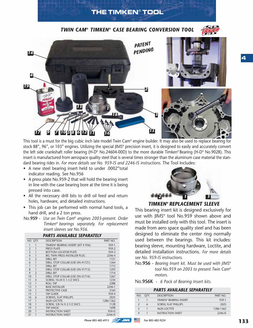
133
4
Phone 805-482-6913 Fax 805-482-9224
THE TIMKEN® TOOL
TWIN CAM® TIMKEN® CASE BEARING CONVERSION TOOL
PARTS AVAILABLE SEPARATELYNO. QTY. DESCRIPTION PART NO.
1 1 TIMKEN® BEARING INSERT (KIT # 956) 959-12 1 PRESS PLATE 959-23 1 BOTTOM LOCATOR PLATE 959-34 1 BIG TWIN PRESS INSTALLER PLUG 2246-4 5 2 DRILL BIT 17216 1 DRILL STOP COLLAR (USE ON #1721) 12647 1 DRILL BIT 17138 1 DRILL STOP COLLAR (USE ON #1713) 12929 2 DRILL BIT 171410 1 DRILL STOP COLLAR (USE ON #1714) 1267 11 4 SCREW, 10-24 X 1-1/2 SHCS 123412 1 ROLL TAP 228813 1 BASE INSTALLER 2246-114 1 PROTECTIVE CASE 216515 1 TAP GUIDE 959-416 6 SCREWS, FLAT PHILLIPS 202517 1 #620 LOCTITE 1286-1362 18 1 SCREW, 3/8-16 X 2-1/2 SHCS 1128 19 1 TAP MAGIC 169820 1 INSTRUCTION SHEET 959-IS21 1 INSTRUCTION SHEET 2246-IS
TIMKEN® REPLACEMENT SLEEVEThis bearing insert kit is designed exclusively foruse with JIMS® tool No.959 shown above andmust be installed only with this tool. The insert ismade from aero space quality steel and has beendesigned to eliminate the center ring normallyused between the bearings. This kit includes:bearing sleeve, mounting hardware, Loctite, anddetailed installation instructions. For more detailssee No. 959-IS instructions.No.956 - Bearing Insert kit. Must be used with JIMS®
tool No.959 on 2003 to present Twin Cam®
motors. No.956K - 6 Pack of Bearing Insert kits.
14
18
8 65 12
13
2
3
151611107917
19
4
1
12 3
PATENT
PENDING
This tool is a must for the big cubic inch late model Twin Cam® engine builder. It may also be used to replace bearing forstock 88”, 96”, or 103” engines. Utilizing the special JIMS® precision insert, it is designed to easily and accurately convertthe left side crankshaft roller bearing (H-D® No.24604-00D) to the more durable Timken® Bearing (H-D® No.9028). Thisinsert is manufactured from aerospace quality steel that is several times stronger than the aluminum case material the stan-dard bearing rides in. For more details see No. 959-IS and 2246-IS instructions. The Tool Includes:• A new steel bearing insert held to under .0002”total
indicator reading. See No.956• A press plate No.959-2 that will hold the bearing insert
in line with the case bearing bore at the time it is beingpressed into case.
• All the necessary drill bits to drill oil feed and returnholes, hardware, and detailed instructions.
• This job can be performed with normal hand tools, ahand drill, and a 2 ton press.
No.959 - Use on Twin Cam® engines 2003-present. OrderTimken® bearings separately. For replacementinsert sleeves see No.956.
PARTS AVAILABLE SEPARATELYNO. QTY. DESCRIPTION PART NO.
1 1 TIMKEN® BEARING INSERT 959-1
2 6 SCREW, FLAT PHILLIPS 2025
3 1 #620 LOCTITE 1286-1362
4 1 INSTRUCTION SHEET 2246-IS
MASTER 2013 CATALOG_JMS 2.qxp:Layout 1 8/2/12 8:29 PM Page 133
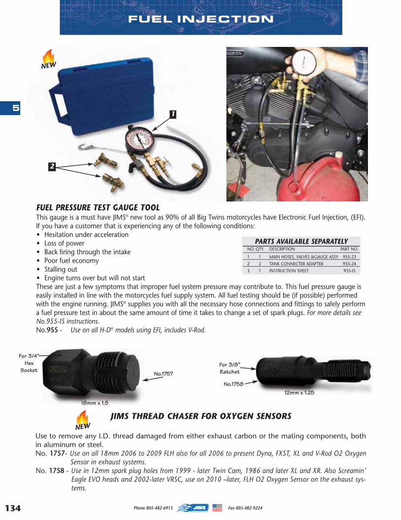
134
5
FUEL INJECTION
2
1
FUEL PRESSURE TEST GAUGE TOOLThis gauge is a must have JIMS® new tool as 90% of all Big Twins motorcycles have Electronic Fuel Injection, (EFI).If you have a customer that is experiencing any of the following conditions: • Hesitation under acceleration• Loss of power• Back firing through the intake• Poor fuel economy• Stalling out• Engine turns over but will not startThese are just a few symptoms that improper fuel system pressure may contribute to. This fuel pressure gauge iseasily installed in line with the motorcycles fuel supply system. All fuel testing should be (if possible) performedwith the engine running. JIMS® supplies you with all the necessary hose connections and fittings to safely performa fuel pressure test in about the same amount of time it takes to change a set of spark plugs. For more details seeNo.955-IS instructions.No.955 - Use on all H-D® models using EFI, includes V-Rod.
PARTS AVAILABLE SEPARATELYNO. QTY. DESCRIPTION PART NO.
1 1 MAIN HOSES, VALVES &GAUGE ASSY 955-23
2 2 TANK CONNECTER ADAPTER 955-24
3 1 INSTRUCTION SHEET 955-IS
NEW
NEWJIMS THREAD CHASER FOR OXYGEN SENSORS
Use to remove any I.D. thread damaged from either exhaust carbon or the mating components, bothin aluminum or steel.No. 1757- Use on all 18mm 2006 to 2009 FLH also for all 2006 to present Dyna, FXST, XL and V-Rod O2 Oxygen
Sensor in exhaust systems.No. 1758 - Use in 12mm spark plug holes from 1999 - later Twin Cam, 1986 and later XL and XR. Also Screamin’
Eagle EVO heads and 2002-later VRSC, use on 2010 –later, FLH O2 Oxygen Sensor on the exhaust sys-tems.
No.1757
No.1758
For 3/4”Hex
Socket
18mm x 1.5
12mm x 1.25
For 3/8”Ratchet
Phone 805-482-6913 Fax 805-482-9224
MASTER 2013 CATALOG_JMS 2.qxp:Layout 1 8/2/12 8:29 PM Page 134
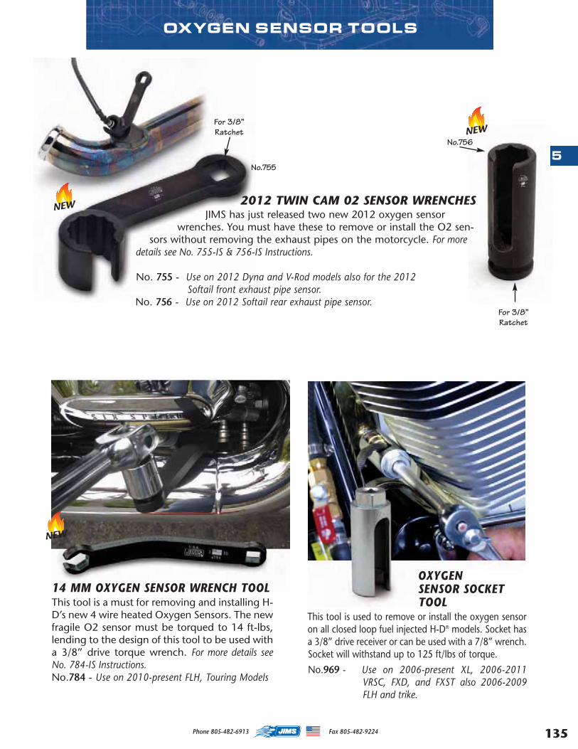
135
OXYGEN SENSOR TOOLS
OXYGENSENSOR SOCKETTOOL
This tool is used to remove or install the oxygen sensoron all closed loop fuel injected H-D® models. Socket hasa 3/8” drive receiver or can be used with a 7/8” wrench.Socket will withstand up to 125 ft/lbs of torque.
No.969 - Use on 2006-present XL, 2006-2011VRSC, FXD, and FXST also 2006-2009FLH and trike.
2012 TWIN CAM 02 SENSOR WRENCHESJIMS has just released two new 2012 oxygen sensor
wrenches. You must have these to remove or install the O2 sen-sors without removing the exhaust pipes on the motorcycle. For more
details see No. 755-IS & 756-IS Instructions.
No. 755 - Use on 2012 Dyna and V-Rod models also for the 2012Softail front exhaust pipe sensor.
No. 756 - Use on 2012 Softail rear exhaust pipe sensor.
No.755
No.756
14 MM OXYGEN SENSOR WRENCH TOOLThis tool is a must for removing and installing H-D’s new 4 wire heated Oxygen Sensors. The newfragile O2 sensor must be torqued to 14 ft-lbs,lending to the design of this tool to be used witha 3/8” drive torque wrench. For more details seeNo. 784-IS Instructions. No.784 - Use on 2010-present FLH, Touring Models
NEW
NEW
NEWFor 3/8”Ratchet
For 3/8”Ratchet
5
Phone 805-482-6913 Fax 805-482-9224
MASTER 2013 CATALOG_JMS 2.qxp:Layout 1 8/2/12 8:29 PM Page 135
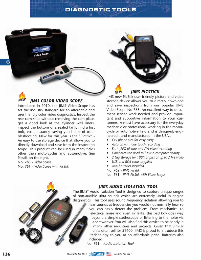
136
DIAGNOSTIC TOOLS
JIMS AUDIO ISOLATION TOOLThe JIMS® Audio Isolation Tool is designed to capture unique rangesof non-audible ultra sounds which are extremely useful in enginediagnostics. This tool uses sound frequency isolation allowing you to
hear sounds at frequencies you would not normally hear soyou can easily detect the problem. From mechanical toelectrical noise and even air leaks, this bad boy goes waybeyond a simple stethoscope or listening to the noise viaa screwdriver. You will also find this device to be handy inmany other industries and projects. Given that similarunits often sell for $1400, JIMS is proud to introduce this
technology to you at an affordable price. Batteries alsoincluded.
No. 763 – Audio Isolation Tool
NEW
JIMS PICSTICKJIMS new PicStik user friendly picture and videostorage device allows you to directly downloadand save inspections from our popular JIMSVideo Scope No 783. An excellent way to docu-ment service work needed and provide impor-tant and supportive information to your cus-tomers. A must have accessory for the everydaymechanic or professional working in the motor-cycle or automotive field and is designed, engi-neered , and manufactured in the USA.. • Cell phone size for easy carry• Auto on with one touch recording• Both JPEG picture and AVI video recording• Eliminates the need to have a computer nearby• 2 Gig storage for 100’s of pics or up to 2 hrs video• USB and RCA cords supplied • AAA batteries included No. 762 - JIMS PicStik No. 761 - JIMS PicStik with Video Scope
JIMS COLOR VIDEO SCOPEIntroduced in 2010, the JIMS Video Scope hasset the industry standard for an affordable anduser friendly color video diagnostics. Inspect therear cam shoe without removing the cam plate,get a good look at the cylinder wall liners,inspect the bottom of a sealed tank, find a lostbolt, etc... Instantly saving you hours of trou-bleshooting. New for this year is the “Picstik” -An easy to use storage device that allows you todirectly download and save from the inspectionscope. This product can be used in many fieldsother then motorcycles and automotive. SeePicstik on the right. No. 783 - Video Scope No. 761 - Video Scope with PicStik
NEW
NEW
6
Phone 805-482-6913 Fax 805-482-9224
MASTER 2013 CATALOG_JMS 2.qxp:Layout 1 8/2/12 8:29 PM Page 136
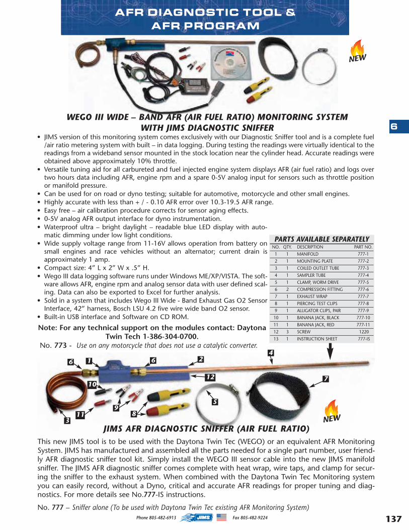
137
6
AFR DIAGNOSTIC TOOL & AFR PROGRAM
JIMS AFR DIAGNOSTIC SNIFFER (AIR FUEL RATIO)This new JIMS tool is to be used with the Daytona Twin Tec (WEGO) or an equivalent AFR MonitoringSystem. JIMS has manufactured and assembled all the parts needed for a single part number, user friend-ly AFR diagnostic sniffer tool kit. Simply install the WEGO III sensor cable into the new JIMS manifoldsniffer. The JIMS AFR diagnostic sniffer comes complete with heat wrap, wire taps, and clamp for secur-ing the sniffer to the exhaust system. When combined with the Daytona Twin Tec Monitoring systemyou can easily record, without a Dyno, critical and accurate AFR readings for proper tuning and diag-nostics. For more details see No.777-IS instructions.
No. 777 – Sniffer alone (To be used with Daytona Twin Tec existing AFR Monitoring System)
NEW
WEGO III WIDE – BAND AFR (AIR FUEL RATIO) MONITORING SYSTEM WITH JIMS DIAGNOSTIC SNIFFER
• JIMS version of this monitoring system comes exclusively with our Diagnostic Sniffer tool and is a complete fuel/air ratio metering system with built – in data logging. During testing the readings were virtually identical to thereadings from a wideband sensor mounted in the stock location near the cylinder head. Accurate readings wereobtained above approximately 10% throttle.
• Versatile tuning aid for all carbureted and fuel injected engine system displays AFR (air fuel ratio) and logs overtwo hours data including AFR, engine rpm and a spare 0-5V analog input for sensors such as throttle positionor manifold pressure.
• Can be used for on road or dyno testing; suitable for automotive, motorcycle and other small engines. • Highly accurate with less than + / - 0.10 AFR error over 10.3-19.5 AFR range.• Easy free – air calibration procedure corrects for sensor aging effects.• 0-5V analog AFR output interface for dyno instrumentation.• Waterproof ultra – bright daylight – readable blue LED display with auto-
matic dimming under low light conditions.• Wide supply voltage range from 11-16V allows operation from battery on
small engines and race vehicles without an alternator; current drain isapproximately 1 amp.
• Compact size: 4” L x 2” W x .5” H.• Wego III data logging software runs under Windows ME/XP/VISTA. The soft-
ware allows AFR, engine rpm and analog sensor data with user defined scal-ing. Data can also be exported to Excel for further analysis.
• Sold in a system that includes Wego III Wide - Band Exhaust Gas O2 SensorInterface, 42” harness, Bosch LSU 4.2 five wire wide band O2 sensor.
• Built-in USB interface and Software on CD ROM.
Note: For any technical support on the modules contact: DaytonaTwin Tech 1-386-304-0700.
No. 773 - Use on any motorcycle that does not use a catalytic converter.
NEW
6 1 6 24
7
5
89
11
12
3
10
PARTS AVAILABLE SEPARATELYNO. QTY. DESCRIPTION PART NO.
1 1 MANIFOLD 777-1
2 1 MOUNTING PLATE 777-2
3 1 COILED OUTLET TUBE 777-3
4 1 SAMPLER TUBE 777-4
5 1 CLAMP, WORM DRIVE 777-5
6 2 COMPRESSION FITTING 777-6
7 1 EXHAUST WRAP 777-7
8 1 PIERCING TEST CLIPS 777-8
9 1 ALLIGATOR CLIPS, PAIR 777-9
10 1 BANANA JACK, BLACK 777-10
11 1 BANANA JACK, RED 777-11
12 3 SCREW 1220
13 1 INSTRUCTION SHEET 777-IS
Phone 805-482-6913 Fax 805-482-9224
MASTER 2013 CATALOG_JMS 2.qxp:Layout 1 8/2/12 8:29 PM Page 137
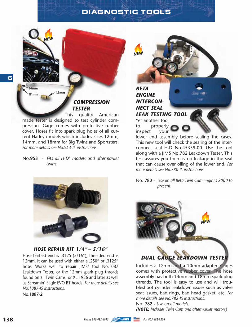
138
DIAGNOSTIC TOOLS
COMPRESSIONTESTER
This quality Americanmade tester is designed to test cylinder com-pression. Gage comes with protective rubbercover. Hoses fit into spark plug holes of all cur-rent Harley models which includes sizes 12mm,14mm, and 18mm for Big Twins and Sportsters.For more details see No.953-IS instructions.
No.953 - Fits all H-D® models and aftermarkettwins.
HOSE REPAIR KIT 1/4” – 5/16”Hose barbed end is .3125 (5/16”), threaded end is12mm. It can be used with either a .250” or .3125”hose. Works well to repair JIMS® tool No.1087Leakdown Tester, or the 12mm spark plug threadsfound on all Twin Cams, or XL 1986 and later as wellas Screamin’ Eagle EVO BT heads. For more details seeNo.1087-IS instructions. No.1087-2
BETAENGINEINTERCON-NECT SEALLEAK TESTING TOOLYet another toolto properlyinspect yourlower end assembly before sealing the cases.This new tool will check the sealing of the inter-connect seal H-D No.45359-00. Use the toolalong with a JIMS No.782 Leakdown Tester. Thistest assures you there is no leakage in the sealthat can cause over oiling of the lower end. Formore details see No.780-IS instructions.
No. 780 - Use on all Beta Twin Cam engines 2000 topresent.
NEW
NEW
NEW
DUAL GAUGE LEAKDOWN TESTERIncludes a 12mm and a 10mm adapter. Gagescomes with protective rubber cover. The hoseassembly has both 14mm and 18mm spark plugthreads. The tool is easy to use and will trou-bleshoot cylinder leakdown issues such as valveseat issues, bad rings, bad head gasket, etc. Formore details see No.782-IS instructions. No. 782 - Use on all models. (NOTE: Includes Twin Cam and aftermarket motors)
14mm
18mm 12mm
6
Phone 805-482-6913 Fax 805-482-9224
MASTER 2013 CATALOG_JMS 2.qxp:Layout 1 8/2/12 8:29 PM Page 138

139
6
This diagnostic Scantool from BDM retrieves trouble codes and displays an array of sensor levels for ECM controlledfuel injected and carbureted Big Twins. In conjunction with your Harley Davidson® service manual, this tool canquickly and accurately diagnose many common and complex problems. This Scantool has multi-functions thatallow you to monitor your system’s status in areas such as; injector cycles, ignition spark, RPM, and much more.The main unit is protected by a rubberized jacket that is both durable, and easy to hold. The large LCD screen iseasy to read and is backlit for low lit situations. The software is delivered via an upgradeable cartridge specificallydesigned for use on Harley Davidsons®, and all harnesses and adapters are included as well a comprehensive instruc-tion manual. If you are at all leery of purchasing a new product with this level of sophistication, consider that thisexact platform has been used in the automotive industry for many years, and it’s been bullet proof! No.1149 - Use on Delphi fuel injection models 2001-05, except V-Rod. This BDM Kit includes a Delphi software cartridge.No.1249 - Use on Delphi fuel injection models 2001-05, except V-Rod. Delphi software cartridge only.No.1159 - Use on Magnetti Marelli fuel injected models 1995-01 and all carbureted Twin Cam® models 1999-03. This
software cartridge only can be used with the No.1149 BDM Kit.
EASY TO READ MENUS
BDM KIT INCLUDES1 Bi-Directional Scantool2 Custom Carrying Case3 8ft Main Diagnostic Cable4 Harley® Adapter Harness5 Harley Software Cartridge6 BDM Operations Manual7 12V Power Supply8 4 AA Batteries
UPGRADEABLE SOFTWARE
CARTRIDGE!
DYNAMIC REAL TIME CHARTS INSTANT DATA REPORTS!
BDM DIAGNOSTIC TOOL
MASTERMIND DIAGNOSTIC SCANTOOL FOR USE ON HARLEY DAVIDSON®
Phone 805-482-6913 Fax 805-482-9224
MASTER 2013 CATALOG_JMS 2.qxp:Layout 1 8/2/12 8:29 PM Page 139
140
7
Phone 805-482-6913 Fax 805-482-9224
IGNITION SWITCH HOUSINGALIGNMENT TOOL
This tool will easily align the ignition switchhousing as the retaining screws are beingtorqued. This gives the ignition switch knob thealignment it needs to help extend the life of theignition switch housing. For more details see No.943-IS instructions.No.943 - Use on all FL Touring models 2003 to
present that have a H-D No.61530-03B.
IGNITION SWITCH CONNECTORREMOVER TOOL
Use this tool to safely remove the ignition switchwiring connector. Slip the dog bone end of toolinto the bottom side of connector until it istouching the back end of connector box. Thengently pull out the male wiring connector andtool. For more details see No. 942-IS instructions.No.942 - Use on all FL Touring models 2003 to
present that have a H-D No.61530-03B.
IGNITION TOOLS
Chicago Joe (Nitro blast)
MASTER 2013 CATALOG_JMS 2.qxp:Layout 1 8/2/12 8:29 PM Page 140
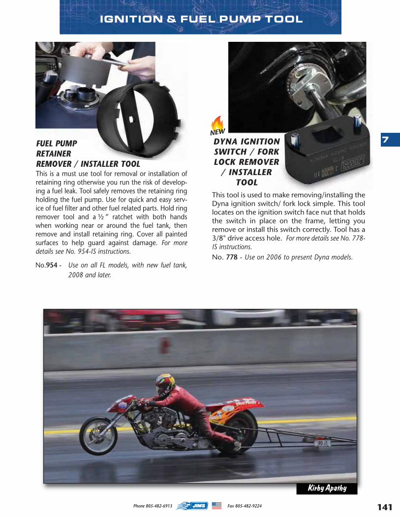
141
7
Phone 805-482-6913 Fax 805-482-9224
IGNITION & FUEL PUMP TOOL
FUEL PUMPRETAINERREMOVER / INSTALLER TOOLThis is a must use tool for removal or installation ofretaining ring otherwise you run the risk of develop-ing a fuel leak. Tool safely removes the retaining ringholding the fuel pump. Use for quick and easy serv-ice of fuel filter and other fuel related parts. Hold ringremover tool and a ½ ” ratchet with both handswhen working near or around the fuel tank, thenremove and install retaining ring. Cover all paintedsurfaces to help guard against damage. For moredetails see No. 954-IS instructions.
No.954 - Use on all FL models, with new fuel tank,2008 and later.
DYNA IGNITIONSWITCH / FORKLOCK REMOVER
/ INSTALLERTOOL
This tool is used to make removing/installing theDyna ignition switch/ fork lock simple. This toollocates on the ignition switch face nut that holdsthe switch in place on the frame, letting youremove or install this switch correctly. Tool has a3/8" drive access hole. For more details see No. 778-IS instructions.No. 778 - Use on 2006 to present Dyna models.
NEW
Kirby Apathy
MASTER 2013 CATALOG_JMS 2.qxp:Layout 1 8/2/12 8:29 PM Page 141

142
7
Phone 805-482-6913 Fax 805-482-9224
6-IN-1 STAR RECEPTACLE EXTRACTORSEasily remove anassortment of har-ness style receptaclepins with either ofthese 6-in-1 tools.Designed for auto-mobiles, we havefound these to workequally well onHarley-Davidsons®.
No.1763 - Use on ALDL, Pack-Con, and weather connectors.
No.1764 - Use on most compression tong style connectors.
RECEPTACLE& PIN
EXTRACTOREasily removesthe molex stylepin from con-nectors. For
more details see No.2121-IS instructions.
No.2121A - Pin Extractor- Use on all models.No.2122A - Receptacle Extractor- Use on all models.
No.1763No.1764
ELECTRICAL TOOLS
JIMS 12MM X 1.25 THREAD CHASERFOR SPARK PLUG AND OXYGEN SENSORSUse to remove any I.D. thread damage that mayhave come from either exhaust carbon or the mat-ing components, both in aluminum or steel.
No. 1758 - Use in spark plug holes from 1999 - laterTwin Cam, 1986 and later XL and XR.Also Screamin’ Eagle EVO heads and2002-later VRSC, use on 2010 –later,FLH O2 Oxygen Sensor on the exhaustsystems.
NEW
14MM & 18MMSPARK PLUG HOLE THREAD CHASER
This double-ended, 14mm and 18mm thread chasereasily cleans-up spark plug holes, reducing thechance of cross threading. Use with 13/16” socket.
No.1770 - Use on all 14mm and 18mm spark plugholes.
WIRE PIERCING TOOL KITThis tool isused whenyour lookingfor an easyway to pierceinto positiveor negativep o w e rsources in awire harness.Fits wiresfrom .030”t h r o u g h.180” diameter insulation. Do not use on voltageslarger than 30VAC or 60VDC. Maximum current 5 A.Tool comes with banana jacks on tool. Included are ared & black banana post connectors.
No. 758 – Use on any wire from .030” through .180”diameter insulation.
NEW
No.1757
NEW
18MM O2 SENSOR THREAD CHASERNo. 1757- Use on all 2006 to 2009 FLH also for all
2006 to present Dyna, FXST, XL and V-Rod O2 Oxygen Sensor in exhaust sys-tems.
For 3/8”Ratchet
MASTER 2013 CATALOG_JMS 2.qxp:Layout 1 8/2/12 8:29 PM Page 142
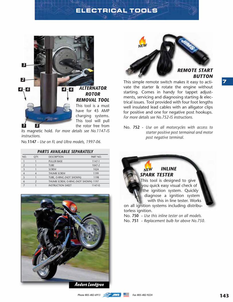
143
7
Phone 805-482-6913 Fax 805-482-9224
ELECTRICAL TOOLS
ALTERNATORROTOR
REMOVAL TOOLThis tool is a musthave for 45 AMPcharging systems.This tool will pullthe rotor free from
its magnetic hold. For more details see No.1147-ISinstructions.No.1147 - Use on FL and Ultra models, 1997-06.
PARTS AVAILABLE SEPARATELYNO. QTY. DESCRIPTION PART NO.
1 1 PULLER BASE 1147-1
2 1 TUBE 1047-2
3 1 SCREW 1024
4 4 THUMB SCREW 1199
5 1 TUBE, O-RING (NOT SHOWN) 1198
6 2 THUMB SCREW, O-RING (NOT SHOWN) 1197
7 1 INSTRUCTION SHEET 1147-IS
1
3
4
2
5
64 6
REMOTE START BUTTON
This simple remote switch makes it easy to acti-vate the starter & rotate the engine withoutstarting. Comes in handy for tappet adjust-ments, servicing and diagnosing starting & elec-trical issues. Tool provided with four foot lengthswell insulated lead cables with an alligator clipsfor positive and one for negative post hookups.For more details see No.752-IS instructions.
No. 752 - Use on all motorcycles with access tostarter positive post termainal and motorpost negative terminal.
INLINESPARK TESTER This tool is designed to giveyou quick easy visual check ofthe ignition system. Quicklydiagnose a ignition system
with this in line tester. Workson all ignition systems including distribu-torless ignition.No. 750 - Use this inline tester on all models.No. 751 - Replacement bulb for above No.750.
NEW
NEW
Anders Lundgren
MASTER 2013 CATALOG_JMS 2.qxp:Layout 1 8/2/12 8:29 PM Page 143
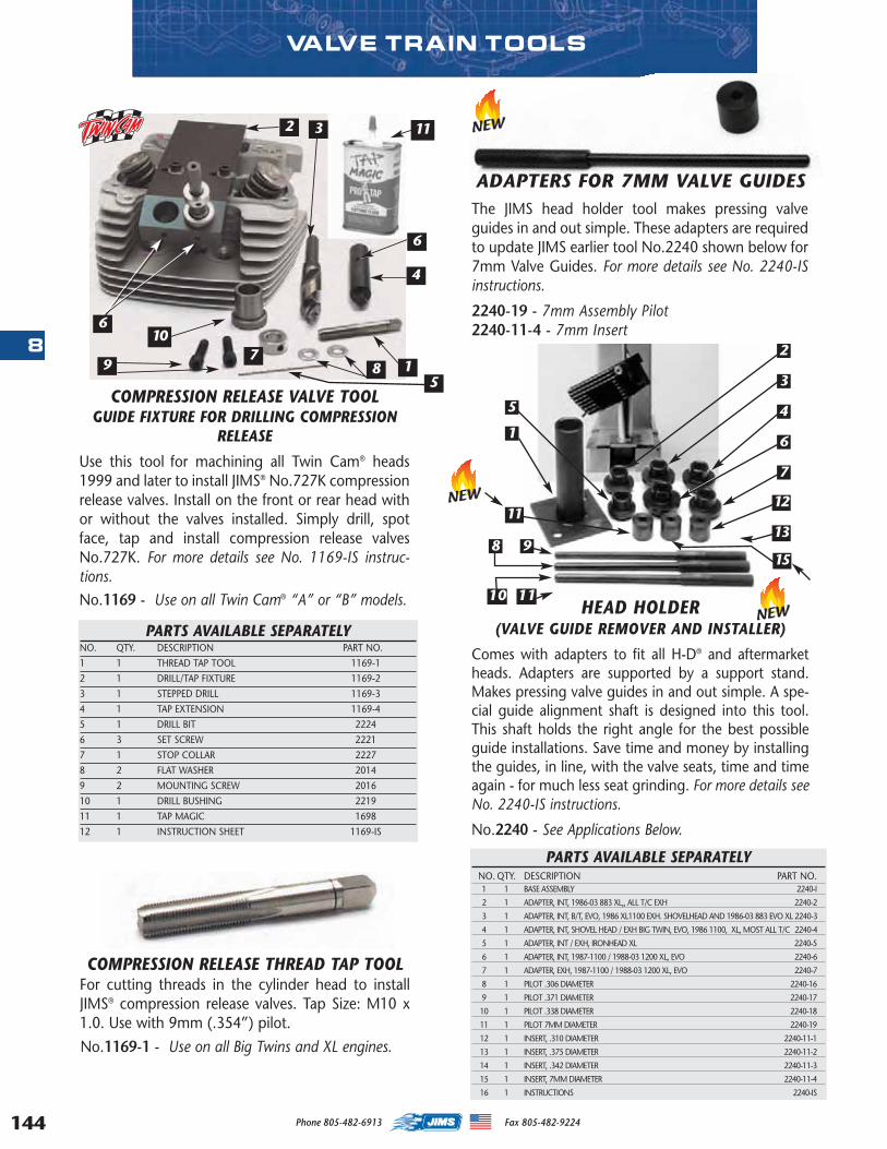
144
8
Phone 805-482-6913 Fax 805-482-9224
VALVE TRAIN TOOLS
COMPRESSION RELEASE VALVE TOOLGUIDE FIXTURE FOR DRILLING COMPRESSION
RELEASE
Use this tool for machining all Twin Cam® heads1999 and later to install JIMS® No.727K compressionrelease valves. Install on the front or rear head withor without the valves installed. Simply drill, spotface, tap and install compression release valvesNo.727K. For more details see No. 1169-IS instruc-tions.No.1169 - Use on all Twin Cam® “A” or “B” models.
PARTS AVAILABLE SEPARATELYNO. QTY. DESCRIPTION PART NO.
1 1 THREAD TAP TOOL 1169-1
2 1 DRILL/TAP FIXTURE 1169-2
3 1 STEPPED DRILL 1169-3
4 1 TAP EXTENSION 1169-4
5 1 DRILL BIT 2224
6 3 SET SCREW 2221
7 1 STOP COLLAR 2227
8 2 FLAT WASHER 2014
9 2 MOUNTING SCREW 2016
10 1 DRILL BUSHING 2219
11 1 TAP MAGIC 1698
12 1 INSTRUCTION SHEET 1169-IS
2
95
8 1
4
6
7
3 11
10
COMPRESSION RELEASE THREAD TAP TOOLFor cutting threads in the cylinder head to installJIMS® compression release valves. Tap Size: M10 x1.0. Use with 9mm (.354”) pilot.
No.1169-1 - Use on all Big Twins and XL engines.
ADAPTERS FOR 7MM VALVE GUIDESThe JIMS head holder tool makes pressing valveguides in and out simple. These adapters are requiredto update JIMS earlier tool No.2240 shown below for7mm Valve Guides. For more details see No. 2240-ISinstructions.
2240-19 - 7mm Assembly Pilot2240-11-4 - 7mm Insert
1
2
7
1113
12
3
6
45
10
98
PARTS AVAILABLE SEPARATELYNO. QTY. DESCRIPTION PART NO.1 1 BASE ASSEMBLY 2240-I
2 1 ADAPTER, INT, 1986-03 883 XL,, ALL T/C EXH 2240-2
3 1 ADAPTER, INT, B/T, EVO, 1986 XL1100 EXH. SHOVELHEAD AND 1986-03 883 EVO XL 2240-3
4 1 ADAPTER, INT, SHOVEL HEAD / EXH BIG TWIN, EVO, 1986 1100, XL, MOST ALL T/C 2240-4
5 1 ADAPTER, INT / EXH, IRONHEAD XL 2240-5
6 1 ADAPTER, INT, 1987-1100 / 1988-03 1200 XL, EVO 2240-6
7 1 ADAPTER, EXH, 1987-1100 / 1988-03 1200 XL, EVO 2240-7
8 1 PILOT .306 DIAMETER 2240-16
9 1 PILOT .371 DIAMETER 2240-17
10 1 PILOT .338 DIAMETER 2240-18
11 1 PILOT 7MM DIAMETER 2240-19
12 1 INSERT, .310 DIAMETER 2240-11-1
13 1 INSERT, .375 DIAMETER 2240-11-2
14 1 INSERT, .342 DIAMETER 2240-11-3
15 1 INSERT, 7MM DIAMETER 2240-11-4
16 1 INSTRUCTIONS 2240-IS
11
15
HEAD HOLDER (VALVE GUIDE REMOVER AND INSTALLER)
Comes with adapters to fit all H-D® and aftermarketheads. Adapters are supported by a support stand.Makes pressing valve guides in and out simple. A spe-cial guide alignment shaft is designed into this tool.This shaft holds the right angle for the best possibleguide installations. Save time and money by installingthe guides, in line, with the valve seats, time and timeagain - for much less seat grinding. For more details seeNo. 2240-IS instructions.
No.2240 - See Applications Below.
6
NEW
NEW
NEW
MASTER 2013 CATALOG_JMS 2.qxp:Layout 1 8/2/12 8:29 PM Page 144
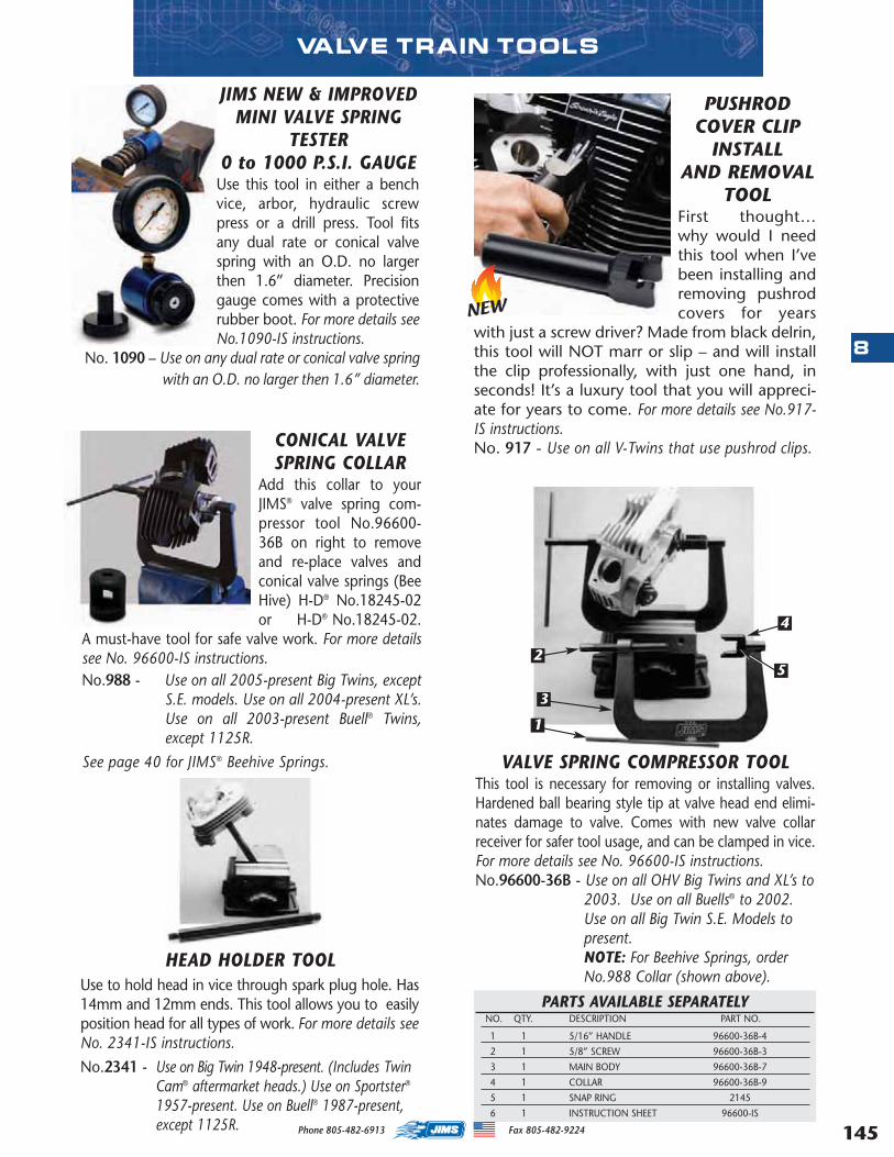
145
8
Phone 805-482-6913 Fax 805-482-9224
PUSHRODCOVER CLIP
INSTALLAND REMOVAL
TOOLFirst thought…why would I needthis tool when I’vebeen installing andremoving pushrodcovers for years
with just a screw driver? Made from black delrin,this tool will NOT marr or slip – and will installthe clip professionally, with just one hand, inseconds! It’s a luxury tool that you will appreci-ate for years to come. For more details see No.917-IS instructions.No. 917 - Use on all V-Twins that use pushrod clips.
PARTS AVAILABLE SEPARATELYNO. QTY. DESCRIPTION PART NO.
1 1 5/16” HANDLE 96600-36B-4
2 1 5/8” SCREW 96600-36B-3
3 1 MAIN BODY 96600-36B-7
4 1 COLLAR 96600-36B-9
5 1 SNAP RING 2145
6 1 INSTRUCTION SHEET 96600-IS
VALVE SPRING COMPRESSOR TOOLThis tool is necessary for removing or installing valves.Hardened ball bearing style tip at valve head end elimi-nates damage to valve. Comes with new valve collarreceiver for safer tool usage, and can be clamped in vice.For more details see No. 96600-IS instructions.No.96600-36B - Use on all OHV Big Twins and XL’s to
2003. Use on all Buells® to 2002.Use on all Big Twin S.E. Models topresent. NOTE: For Beehive Springs, orderNo.988 Collar (shown above).
2
3
1
5
4
CONICAL VALVESPRING COLLAR
Add this collar to yourJIMS® valve spring com-pressor tool No.96600-36B on right to removeand re-place valves andconical valve springs (BeeHive) H-D® No.18245-02or H-D® No.18245-02.
A must-have tool for safe valve work. For more detailssee No. 96600-IS instructions.No.988 - Use on all 2005-present Big Twins, except
S.E. models. Use on all 2004-present XL’s.Use on all 2003-present Buell® Twins,except 1125R.
See page 40 for JIMS® Beehive Springs.
VALVE TRAIN TOOLS
No.2341 - Use on Big Twin 1948-present. (Includes TwinCam® aftermarket heads.) Use on Sportster®
1957-present. Use on Buell® 1987-present,except 1125R.
HEAD HOLDER TOOLUse to hold head in vice through spark plug hole. Has14mm and 12mm ends. This tool allows you to easilyposition head for all types of work. For more details seeNo. 2341-IS instructions.
NEW
JIMS NEW & IMPROVEDMINI VALVE SPRING
TESTER0 to 1000 P.S.I. GAUGEUse this tool in either a benchvice, arbor, hydraulic screwpress or a drill press. Tool fitsany dual rate or conical valvespring with an O.D. no largerthen 1.6” diameter. Precisiongauge comes with a protectiverubber boot. For more details seeNo.1090-IS instructions.
No. 1090 – Use on any dual rate or conical valve springwith an O.D. no larger then 1.6” diameter.
MASTER 2013 CATALOG_JMS 2.qxp:Layout 1 8/2/12 8:29 PM Page 145
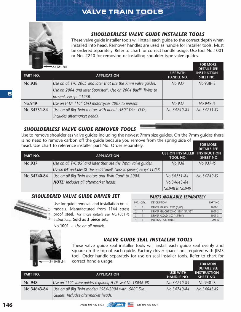
146
8
Phone 805-482-6913 Fax 805-482-9224
FOR MOREDETAILS SEE
SHOULDERLESS VALVE GUIDE REMOVER TOOLSUse to remove shoulderless valve guides including the newest 7mm size guides. On the 7mm guides thereis no need to remove carbon off the guide because you remove from the spring side ofhead. Use chart to reference installer part No. Order separately. FOR MORE
DETAILS SEE
FOR MOREDETAILS SEE
No.938 Use on all T/C 2005 and later that use the 7mm valve guides. No.937 No.938-IS
Use on 2004 and later Sportster®. Use on 2004 Buell® Twins to
present, except 1125R.
No.949 Use on H-D® 110” CVO motorcycles 2007 to present. No.937 No.949-ISNo.34731-84 Use on all Big Twin motors with about .560” Dia.. O.D., No.34740-84 No.34731-IS
Includes aftermarket heads.
VALVE TRAIN TOOLS
SHOULDERLESS VALVE GUIDE INSTALLER TOOLSThese valve guide installer tools will install each guide to the correct depth wheninstalled into head. Remover handles are used as handle for installer tools. Mustbe ordered separately. Refer to chart for correct handle usage. Use tool No.1001or No. 2240 for removing or installing shoulder type valve guides.
VALVE GUIDE SEAL INSTALLER TOOLSThese valve guide seal installer tools will install each guide seal evenly andsquare on the top of each guide. Factory driver spacer not required with JIMStool. Order handle separately for use on seal installer tools. Refer to chart forcorrect handle usage.
34731-84
No.948 Use on 110” valve guides requiring H-D® seal No.18046-98 No.34740-84 No.948-ISNo.34643-84 Use on all Big Twin models 1984-2004 with .560” Dia. No.34740-84 No.34643-IS
Guides. Includes aftermarket heads.
34643-84
No.937 Use on all T/C 05’ and later that use the 7mm valve guides. No.938 No.937-ISUse on 04’ and later XL Use on 04’ Buell® Twins to present, except 1125R.
No.34740-84 Use on all Big Twin motors and Twin Cam® to 2004. No.34731-84 No.34740-ISNOTE: Includes all aftermarket heads. No.34643-84
No.948 & No.949
USE WITH INSTRUCTIONHANDLE NO. SHEET NO.
USE WITH INSTRUCTIONHANDLE NO. SHEET NO.
USE ON INSTALLER INSTRUCTIONTOOL NO. SHEET NO.
SHOULDERED VALVE GUIDE DRIVER SETUse for guide removal and installation on allmodels. Manufactured from 1144 stressproof steel. For more details see No.1001-ISinstructions. Sold as 3 piece set.No.1001 - Use on all models.
➀
➁
➂
PART NO. APPLICATION
PART NO. APPLICATION
PART NO. APPLICATION
PARTS AVAILABLE SEPARATELYNO. QTY. DESCRIPTION PART NO.
1 1 DRIVER /BLACK .370” (3/8”) 1001-1
2 1 DRIVER /BRIGHT ZINC .338” (11/32”) 1001-2
3 1 DRIVER /GOLD .307” (5/16”) 1001-3
4 1 INSTRUCTION SHEET 1001-IS
MASTER 2013 CATALOG_JMS 2.qxp:Layout 1 8/2/12 8:29 PM Page 146
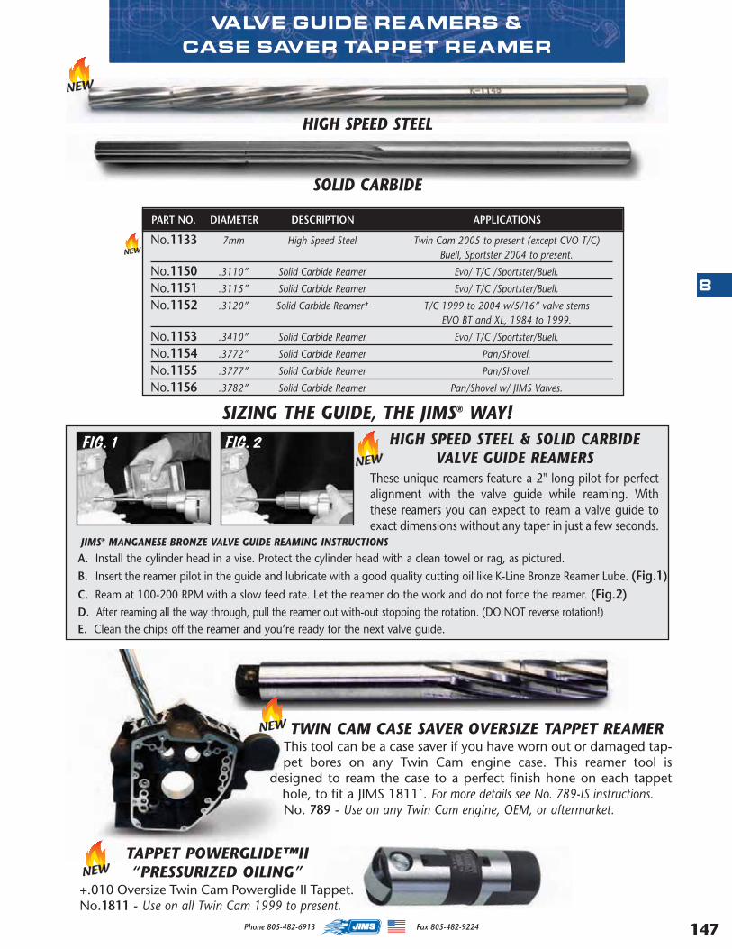
147
8
Phone 805-482-6913 Fax 805-482-9224
TWIN CAM CASE SAVER OVERSIZE TAPPET REAMERThis tool can be a case saver if you have worn out or damaged tap-pet bores on any Twin Cam engine case. This reamer tool is
designed to ream the case to a perfect finish hone on each tappethole, to fit a JIMS 1811`. For more details see No. 789-IS instructions.No. 789 - Use on any Twin Cam engine, OEM, or aftermarket.
VALVE GUIDE REAMERS &CASE SAVER TAPPET REAMER
JIMS® MANGANESE-BRONZE VALVE GUIDE REAMING INSTRUCTIONS
A. Install the cylinder head in a vise. Protect the cylinder head with a clean towel or rag, as pictured. B. Insert the reamer pilot in the guide and lubricate with a good quality cutting oil like K-Line Bronze Reamer Lube. (Fig.1)C. Ream at 100-200 RPM with a slow feed rate. Let the reamer do the work and do not force the reamer. (Fig.2)D. After reaming all the way through, pull the reamer out with-out stopping the rotation. (DO NOT reverse rotation!)E. Clean the chips off the reamer and you’re ready for the next valve guide.
HIGH SPEED STEEL & SOLID CARBIDEVALVE GUIDE REAMERS
These unique reamers feature a 2" long pilot for perfectalignment with the valve guide while reaming. Withthese reamers you can expect to ream a valve guide toexact dimensions without any taper in just a few seconds.
No.1133 7mm High Speed Steel Twin Cam 2005 to present (except CVO T/C) Buell, Sportster 2004 to present.
No.1150 .3110” Solid Carbide Reamer Evo/ T/C /Sportster/Buell.
No.1151 .3115” Solid Carbide Reamer Evo/ T/C /Sportster/Buell.
No.1152 .3120” Solid Carbide Reamer* T/C 1999 to 2004 w/5/16” valve stems EVO BT and XL, 1984 to 1999.
No.1153 .3410” Solid Carbide Reamer Evo/ T/C /Sportster/Buell.
No.1154 .3772” Solid Carbide Reamer Pan/Shovel.
No.1155 .3777” Solid Carbide Reamer Pan/Shovel.
No.1156 .3782” Solid Carbide Reamer Pan/Shovel w/ JIMS Valves.
FIG. 1 FIG. 2
SIZING THE GUIDE, THE JIMS® WAY!
HIGH SPEED STEEL
SOLID CARBIDE
PART NO. DIAMETER DESCRIPTION APPLICATIONS
TAPPET POWERGLIDE™II “PRESSURIZED OILING”
+.010 Oversize Twin Cam Powerglide II Tappet.No.1811 - Use on all Twin Cam 1999 to present.
NEW
NEW
NEW
NEW
NEW
MASTER 2013 CATALOG_JMS 2.qxp:Layout 1 8/2/12 8:29 PM Page 147
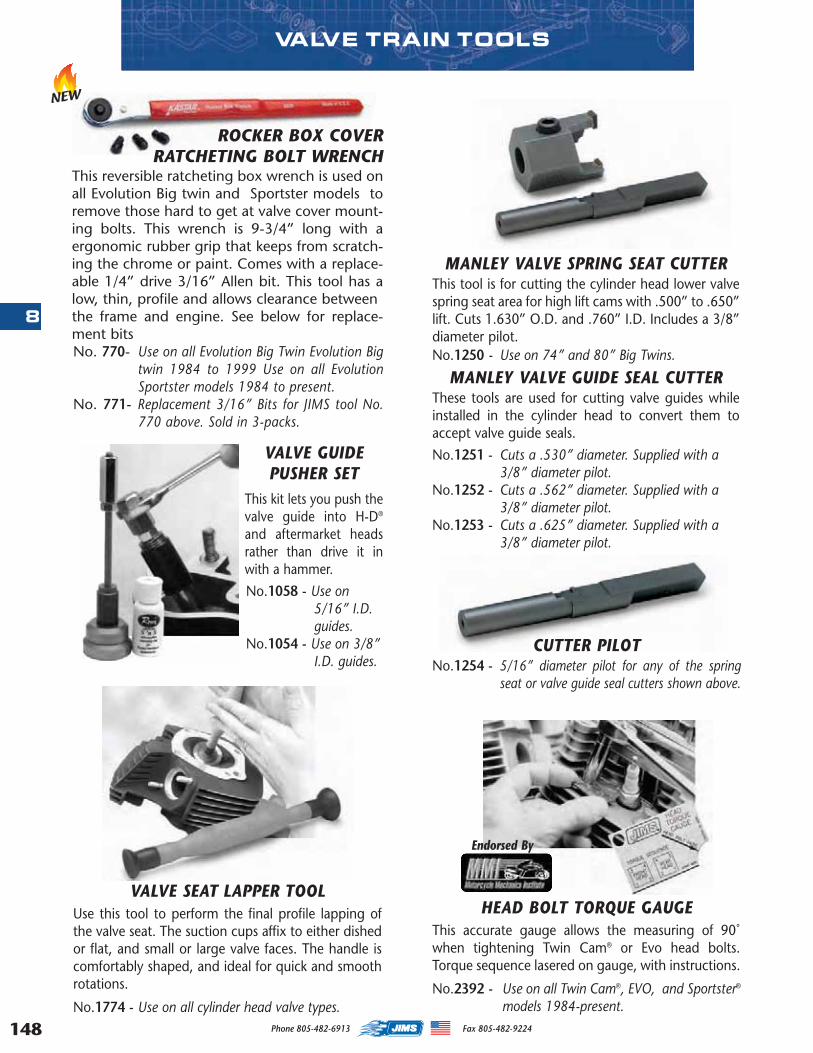
148
8
Phone 805-482-6913 Fax 805-482-9224
VALVE SEAT LAPPER TOOLUse this tool to perform the final profile lapping ofthe valve seat. The suction cups affix to either dishedor flat, and small or large valve faces. The handle iscomfortably shaped, and ideal for quick and smoothrotations.
No.1774 - Use on all cylinder head valve types.
MANLEY VALVE SPRING SEAT CUTTERThis tool is for cutting the cylinder head lower valvespring seat area for high lift cams with .500” to .650”lift. Cuts 1.630” O.D. and .760” I.D. Includes a 3/8”diameter pilot. No.1250 - Use on 74” and 80” Big Twins.
MANLEY VALVE GUIDE SEAL CUTTERThese tools are used for cutting valve guides whileinstalled in the cylinder head to convert them toaccept valve guide seals.
No.1251 - Cuts a .530” diameter. Supplied with a3/8” diameter pilot.
No.1252 - Cuts a .562” diameter. Supplied with a3/8” diameter pilot.
No.1253 - Cuts a .625” diameter. Supplied with a3/8” diameter pilot.
CUTTER PILOTNo.1254 - 5/16” diameter pilot for any of the spring
seat or valve guide seal cutters shown above.
VALVE GUIDEPUSHER SET
This kit lets you push thevalve guide into H-D®
and aftermarket headsrather than drive it inwith a hammer.
No.1058 - Use on5/16” I.D.guides.
No.1054 - Use on 3/8”I.D. guides.
VALVE TRAIN TOOLS
HEAD BOLT TORQUE GAUGEThis accurate gauge allows the measuring of 90˚when tightening Twin Cam® or Evo head bolts.Torque sequence lasered on gauge, with instructions.
No.2392 - Use on all Twin Cam®, EVO, and Sportster®
models 1984-present.
Endorsed By
ROCKER BOX COVER RATCHETING BOLT WRENCH
This reversible ratcheting box wrench is used onall Evolution Big twin and Sportster models toremove those hard to get at valve cover mount-ing bolts. This wrench is 9-3/4” long with aergonomic rubber grip that keeps from scratch-ing the chrome or paint. Comes with a replace-able 1/4” drive 3/16” Allen bit. This tool has alow, thin, profile and allows clearance betweenthe frame and engine. See below for replace-ment bitsNo. 770- Use on all Evolution Big Twin Evolution Big
twin 1984 to 1999 Use on all EvolutionSportster models 1984 to present.
No. 771- Replacement 3/16” Bits for JIMS tool No.770 above. Sold in 3-packs.
NEW
MASTER 2013 CATALOG_JMS 2.qxp:Layout 1 8/2/12 8:29 PM Page 148
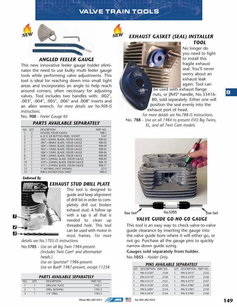
149
8
Phone 805-482-6913 Fax 805-482-9224
VALVE TRAIN TOOLS
This tool is an easy way to check valve-to-valveguide clearance by inserting the gauge intothe valve guide bore where it will either go, ornot go. Purchase all the gauge pins to quicklynarrow down guide sizing. Gauges sold separately from holder.No.1055 - Holder Only.
See list See listNo.1055
VALVE GUIDE GO-NO-GO GAUGE
QTY DESCRIPTION PART NO.
1 PIN 0.3105” 2149
1 PIN 0.3110” 2150
1 PIN 0.3115” 2151
1 PIN 0.3120” 2152
1 PIN 0.3405” 2153
1 PIN 0.3410” 2154
QTY DESCRIPTION PART NO.
1 PIN 0.3415” 2155
1 PIN 0.3770” 2156
1 PIN 0.3775” 2157
1 PIN 0.3780” 2158
1 PIN 0.3785” 2159
1 PIN 0.3790” 2160
PINS AVAILABLE SEPARATELY
PARTS AVAILABLE SEPARATELYNO. QTY. DESCRIPTION PART NO.
1 1 DRILLING PLATE 1705-1
2 1 DRILL BUSHING 1705-2
3 1 1/4” DRILL 1705-3
EXHAUST STUD DRILL PLATEThis tool is designed toguide and keep alignmentof drill bit in order to com-pletely drill out brokenexhaust stud. A follow upwith a tap is all that isneeded to clean upthreaded hole. This toolcan be used with motor inmost frames. For more
details see No.1705-IS instructions.No.1705 - Use on all Big Twin 1984-present.
(Includes Twin Cam® and aftermarketheads.)Use on Sportster® 1986-present.Use on Buell® 1987-present, except 1125R.
Endorsed By
1
2
3
ANGLED FEELER GAUGEThis new innovative feeler gauge holder elimi-nates the need to use bulky multi feeler gaugetools while performing valve adjustments. Thistool is ideal for reaching down into small tightareas and incorporates an angle to help reacharound corners, often necessary for adjustingvalves. Tool includes two handles with: .002",.003", .004", .005", .006" and .008" inserts andan allen wrench. For more details see No.908-ISinstructions.No. 908 - Feeler Gauge Kit
EXHAUST GASKET (SEAL) INSTALLERTOOL
No longer doyou need to fightto install thisfragile exhaustseal. You’ll neverworry about anexhaust leakagain. Tool can
be used with exhaust flangenuts, or JIMS® handle, No.33416-80, sold separately. Either one will
position the seal evenly into theexhaust port of head.
For more details see No.788-IS instructions. No. 788 - Use on all 1984 to present EVO Big Twins,
XL, and all Twin Cam models.
NEWNEW
PARTS AVAILABLE SEPARATELYNO. QTY. DESCRIPTION PART NO.1 2 HOLDER, FEELER GAUGE 908-12 2 6-32 X 3/8 BUTTON HEAD, SOCKET 12473 1 .002”=.05MM, BLADE, FEELER GAUGE 908-024 1 .003”=.08MM, BLADE, FEELER GAUGE 908-035 1 .004”=.10MM, BLADE, FEELER GAUGE 908-046 1 .005”=.13MM, BLADE, FEELER GAUGE 908-057 1 .006”=.15MM, BLADE, FEELER GAUGE 908-068 1 .008”=.20MM, BLADE, FEELER GAUGE 908-089 1 .009”=.229MM, BLADE, FEELER GAUGE 908-09 10 1 .010”=.254MM, BLADE, FEELER GAUGE 908-1011 1 .011”=.279MM, BLADE, FEELER GAUGE 908-1112 1 1” KEY RING (NOT SHOWN) 221313 1 908-IS INSTRUCTION SHEET 908-IS
MASTER 2013 CATALOG_JMS 2.qxp:Layout 1 8/2/12 8:29 PM Page 149
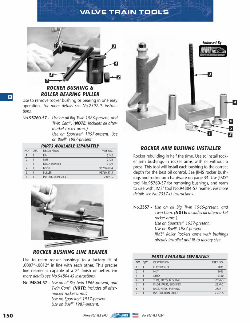
150
8
Phone 805-482-6913 Fax 805-482-9224
ROCKER ARM BUSHING INSTALLERRocker rebuilding in half the time. Use to install rock-er arm bushings in rocker arms with or without apress. This tool will install each bushing to the correctdepth for the best oil control. See JIMS rocker bush-ings and rocker arm hardware on page 34. Use JIMS®
tool No.95760-57 for removing bushings, and reamto size with JIMS® tool No.94804-57 reamer. For moredetails see No.2357-IS instructions.
No.2357 - Use on all Big Twin 1966-present, andTwin Cam. (NOTE: Includes all aftermarketrocker arms.) Use on Sportster® 1957-present.Use on Buell® 1987-present.JIMS® Roller Rockers come with bushingsalready installed and fit to factory size.
ROCKER BUSHING LINE REAMERUse to ream rocker bushings to a factory fit of.0007”-.0012” in line with each other. This preciseline reamer is capable of a 24 finish or better. Formore details see No.94804-IS instructions.
No.94804-57 - Use on all Big Twin 1966-present, andTwin Cam®. (NOTE: Includes all after-market rocker arms.) Use on Sportster® 1957-present.Use on Buell
®
1987-present.
ROCKER BUSHING & ROLLER BEARING PULLER
Use to remove rocker bushing or bearing in one easyoperation. For more details see No.2307-IS instruc-tions.
No.95760-57 - Use on all Big Twin 1966-present, andTwin Cam®. (NOTE: Includes all after-market rocker arms.) Use on Sportster® 1957-present. Useon Buell® 1987-present.
PARTS AVAILABLE SEPARATELYNO. QTY. DESCRIPTION PART NO.
1 1 PIN 2142
2 1 NUT 2128
3 1 BRASS WASHER 2129
4 1 BODY 95760-57-4
5 1 PULLER 95760-57-5
6 1 INSTRUCTION SHEET 2307-IS
PARTS AVAILABLE SEPARATELYNO. QTY. DESCRIPTION PART NO.
1 1 FLAT WASHER 2031
2 1 NUT 2035
3 1 STUD 2360
4 1 TUBE, PRESS, BUSHING 2357-3
5 1 PILOT, PRESS, BUSHING 2357-2
6 1 BASE, PRESS, BUSHING 2357-1
7 1 INSTRUCTION SHEET 2357-IS
VALVE TRAIN TOOLS
Endorsed By
3
4
6
5
21
12
3
4
5
MASTER 2013 CATALOG_JMS 2.qxp:Layout 1 8/2/12 8:29 PM Page 150
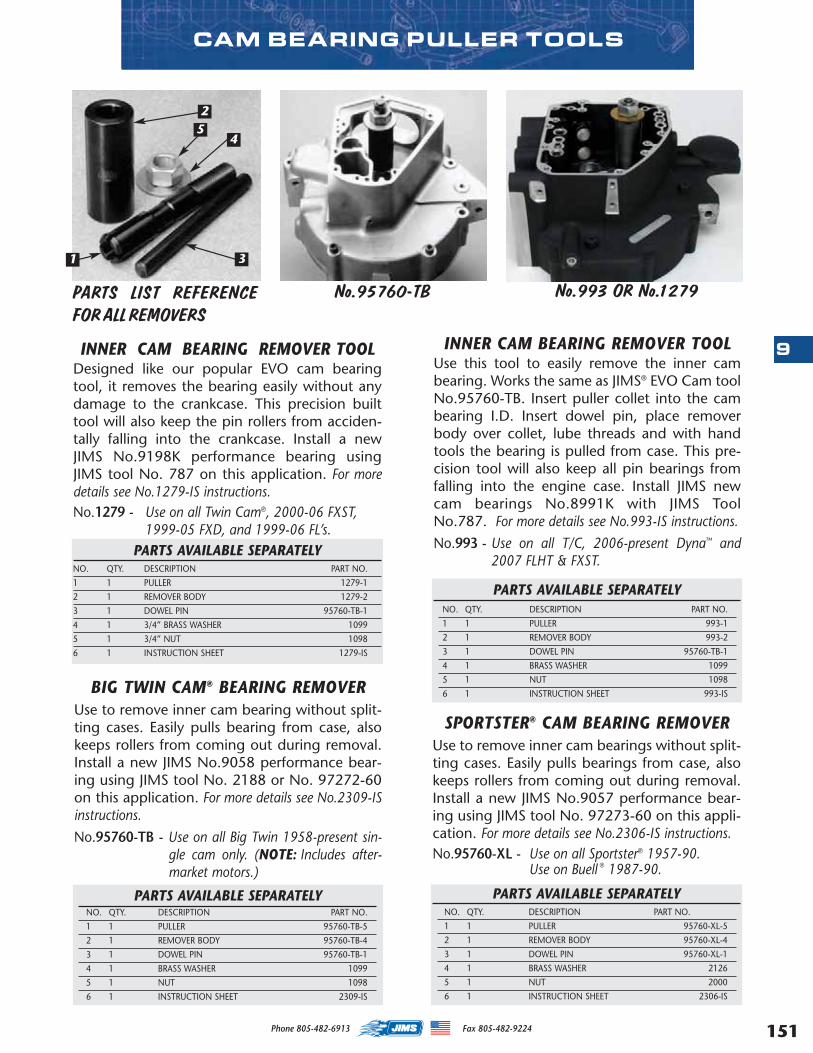
151
9
Phone 805-482-6913 Fax 805-482-9224
BIG TWIN CAM® BEARING REMOVERUse to remove inner cam bearing without split-ting cases. Easily pulls bearing from case, alsokeeps rollers from coming out during removal.Install a new JIMS No.9058 performance bear-ing using JIMS tool No. 2188 or No. 97272-60on this application. For more details see No.2309-ISinstructions.
No.95760-TB - Use on all Big Twin 1958-present sin-gle cam only. (NOTE: Includes after-market motors.)
PARTS AVAILABLE SEPARATELYNO. QTY. DESCRIPTION PART NO.
1 1 PULLER 95760-TB-5
2 1 REMOVER BODY 95760-TB-4
3 1 DOWEL PIN 95760-TB-1
4 1 BRASS WASHER 1099
5 1 NUT 1098
6 1 INSTRUCTION SHEET 2309-IS
SPORTSTER® CAM BEARING REMOVERUse to remove inner cam bearings without split-ting cases. Easily pulls bearings from case, alsokeeps rollers from coming out during removal.Install a new JIMS No.9057 performance bear-ing using JIMS tool No. 97273-60 on this appli-cation. For more details see No.2306-IS instructions. No.95760-XL - Use on all Sportster® 1957-90.
Use on Buell ® 1987-90.
PARTS AVAILABLE SEPARATELYNO. QTY. DESCRIPTION PART NO.
1 1 PULLER 95760-XL-5
2 1 REMOVER BODY 95760-XL-4
3 1 DOWEL PIN 95760-XL-1
4 1 BRASS WASHER 2126
5 1 NUT 2000
6 1 INSTRUCTION SHEET 2306-IS
CAM BEARING PULLER TOOLS
INNER CAM BEARING REMOVER TOOLDesigned like our popular EVO cam bearingtool, it removes the bearing easily without anydamage to the crankcase. This precision builttool will also keep the pin rollers from acciden-tally falling into the crankcase. Install a newJIMS No.9198K performance bearing usingJIMS tool No. 787 on this application. For moredetails see No.1279-IS instructions. No.1279 - Use on all Twin Cam®, 2000-06 FXST,
1999-05 FXD, and 1999-06 FL’s.PARTS AVAILABLE SEPARATELY
NO. QTY. DESCRIPTION PART NO.
1 1 PULLER 1279-1
2 1 REMOVER BODY 1279-2
3 1 DOWEL PIN 95760-TB-1
4 1 3/4” BRASS WASHER 1099
5 1 3/4” NUT 1098
6 1 INSTRUCTION SHEET 1279-IS
INNER CAM BEARING REMOVER TOOLUse this tool to easily remove the inner cambearing. Works the same as JIMS® EVO Cam toolNo.95760-TB. Insert puller collet into the cambearing I.D. Insert dowel pin, place removerbody over collet, lube threads and with handtools the bearing is pulled from case. This pre-cision tool will also keep all pin bearings fromfalling into the engine case. Install JIMS newcam bearings No.8991K with JIMS ToolNo.787. For more details see No.993-IS instructions.
No.993 - Use on all T/C, 2006-present Dyna™ and2007 FLHT & FXST.
PARTS AVAILABLE SEPARATELYNO. QTY. DESCRIPTION PART NO.
1 1 PULLER 993-1
2 1 REMOVER BODY 993-2
3 1 DOWEL PIN 95760-TB-1
4 1 BRASS WASHER 1099
5 1 NUT 1098
6 1 INSTRUCTION SHEET 993-IS
25
4
31
No.95760-TB No.993 OR No.1279PARTS LIST REFERENCEFOR ALL REMOVERS
MASTER 2013 CATALOG_JMS 2.qxp:Layout 1 8/2/12 8:29 PM Page 151

152
9
Phone 805-482-6913 Fax 805-482-9224
TWIN CAM INNER CAM BEARINGINSTALLER
Use this tool to press in, and install, the twoinner cam bearings JIMS® No.8991K. This toolhas been designed to press from the letterside of the inner cam bearings, by putting allthe pushing pressure to the very outer wall ofbearing shell. Eliminats any damage to thebearings, cam and cases. This tool will stop atthe case and set the bearing depth to .023” to.028” below the case surface. Use with JIMS®
Tool No.1279 to remove bearings. For moredetails see No.787-IS instructions.
No.787 - Use on all T/C, 1999-present.
CAM BEARINGTOOLUse to install innercam bearing, withHandle No. 33416-80 on right (Handleslips through theouter cam bushingfor alignment). Allof JIMS® bearinginstallers are
designed with an angle to apply all the pushingforce to the extreme outer diameter of thebearing. For more details see No.97272-IS instruc-tions.
No.97272-60 - Use on all Big Twin 1958-present single cam only.
(Note: Includes aftermarket motors.)
No.97273-60 - Use on all Sportster® 1957-90.Use on Buell® 1987-90.
For more details see No.97273-IS instructions.
INNER CAMBEARING
INSTALLATIONTOOL
This tool easilypresses the innercam bearingsmoothly intothe right case,with the casesassembled, to
the proper depth. Use a new JIMS perform-ance bearing No.9058 and to remove old usetool No. 95760-TB. For more details see No.2188-IS instructions.
No.2188 - Use on all Big Twin 1958-present single camonly. (NOTE: Includes aftermarket motors.)
CAM BEARING INSTALLER TOOLS
PARTS AVAILABLE SEPARATELYNO. QTY. DESCRIPTION PART NO.
1 1 SCREW 1024
2 1 TOOL, CAM BEARING 97272-60
3 1 O-RING 2310
4 1 PLATE 2188-1
5 1 TOOL, DRIVER, CAM BEARING 2190
6 1 INSTRUCTION SHEET 2188-IS
PARTS AVAILABLE SEPARATELYNO. QTY. DESCRIPTION PART NO.
1 1 PLATE INSTALLER 1278-1
2 1 INNER CAM BEARING INSTALLER 1278-3
3 1 SCREW 1024
4 1 SPUD CAM BEARING TOOL 2190
5 4 KNURLED SCREWS 1213
6 1 O-RING 2310
7 1 INSTRUCTION SHEET 787 -IS
1
23
45
RACE & BEARING INSTALL TOOL HANDLEUse with No.s 33071-73, 34810-84, 94547-80A & B,97272-60, and 97273-60. Approximately 12” long. Formore details see No.33416-80-IS instructions.
No.33416-80
1
PARTS AVAILABLE SEPARATELYNO. QTY. DESCRIPTION PART NO.
1 1 O-RING 2310
NEW
2
3
5
61
4
MASTER 2013 CATALOG_JMS 2.qxp:Layout 1 8/2/12 8:29 PM Page 152
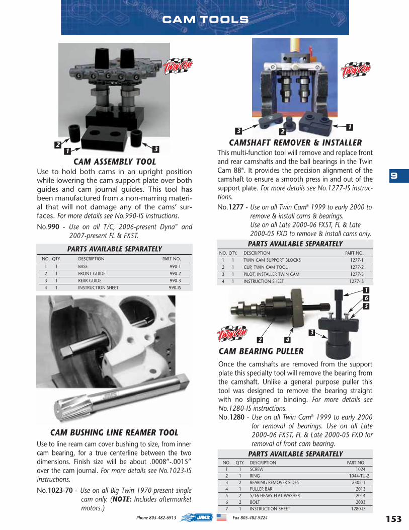
153
9
Phone 805-482-6913 Fax 805-482-9224
2 43
165
CAM TOOLS
CAMSHAFT REMOVER & INSTALLER This multi-function tool will remove and replace frontand rear camshafts and the ball bearings in the TwinCam 88®. It provides the precision alignment of thecamshaft to ensure a smooth press in and out of thesupport plate. For more details see No.1277-IS instruc-tions. No.1277 - Use on all Twin Cam® 1999 to early 2000 to
remove & install cams & bearings.Use on all Late 2000-06 FXST, FL & Late2000-05 FXD to remove & install cams only.
PARTS AVAILABLE SEPARATELYNO. QTY. DESCRIPTION PART NO.
1 1 TWIN CAM SUPPORT BLOCKS 1277-1
2 1 CUP, TWIN CAM TOOL 1277-2
3 1 PILOT, INSTALLER TWIN CAM 1277-3
4 1 INSTRUCTION SHEET 1277-IS
CAM BEARING PULLEROnce the camshafts are removed from the supportplate this specialty tool will remove the bearing fromthe camshaft. Unlike a general purpose puller thistool was designed to remove the bearing straightwith no slipping or binding. For more details seeNo.1280-IS instructions. No.1280 - Use on all Twin Cam® 1999 to early 2000
for removal of bearings. Use on all Late2000-06 FXST, FL & Late 2000-05 FXD forremoval of front cam bearing.
PARTS AVAILABLE SEPARATELYNO. QTY. DESCRIPTION PART NO.
1 1 SCREW 10242 1 RING 1044-TU-23 2 BEARING REMOVER SIDES 2305-14 1 PULLER BAR 20135 2 5/16 HEAVY FLAT WASHER 20146 2 BOLT 20037 1 INSTRUCTION SHEET 1280-IS
CAM BUSHING LINE REAMER TOOLUse to line ream cam cover bushing to size, from innercam bearing, for a true centerline between the twodimensions. Finish size will be about .0008”-.0015”over the cam journal. For more details see No.1023-ISinstructions.
No.1023-70 - Use on all Big Twin 1970-present singlecam only. (NOTE: Includes aftermarketmotors.)
CAM ASSEMBLY TOOLUse to hold both cams in an upright positionwhile lowering the cam support plate over bothguides and cam journal guides. This tool hasbeen manufactured from a non-marring materi-al that will not damage any of the cams’ sur-faces. For more details see No.990-IS instructions.
No.990 - Use on all T/C, 2006-present Dyna™ and2007-present FL & FXST.
PARTS AVAILABLE SEPARATELYNO. QTY. DESCRIPTION PART NO.
1 1 BASE 990-1
2 1 FRONT GUIDE 990-2
3 1 REAR GUIDE 990-3
4 1 INSTRUCTION SHEET 990-IS
231
231
MASTER 2013 CATALOG_JMS 2.qxp:Layout 1 8/2/12 8:29 PM Page 153
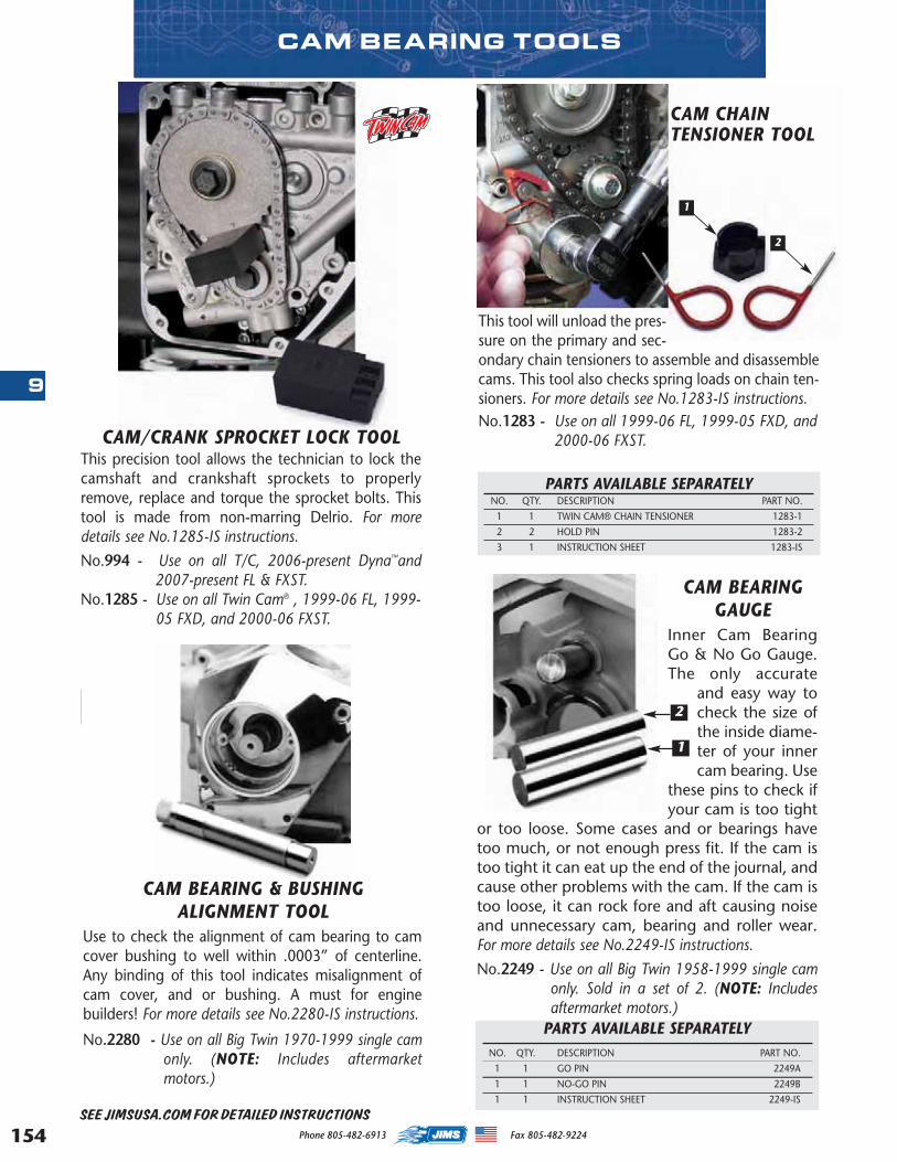
154
9
Phone 805-482-6913 Fax 805-482-9224
SEE JIMSUSA.COM FOR DETAILED INSTRUCTIONS
CAM BEARING TOOLS
CAM BEARING & BUSHING ALIGNMENT TOOL
Use to check the alignment of cam bearing to camcover bushing to well within .0003” of centerline.Any binding of this tool indicates misalignment ofcam cover, and or bushing. A must for enginebuilders! For more details see No.2280-IS instructions.
No.2280 - Use on all Big Twin 1970-1999 single camonly. (NOTE: Includes aftermarketmotors.)
CAM BEARINGGAUGE
Inner Cam BearingGo & No Go Gauge.The only accurate
and easy way tocheck the size ofthe inside diame-ter of your innercam bearing. Use
these pins to check ifyour cam is too tight
or too loose. Some cases and or bearings havetoo much, or not enough press fit. If the cam istoo tight it can eat up the end of the journal, andcause other problems with the cam. If the cam istoo loose, it can rock fore and aft causing noiseand unnecessary cam, bearing and roller wear.For more details see No.2249-IS instructions.
No.2249 - Use on all Big Twin 1958-1999 single camonly. Sold in a set of 2. (NOTE: Includesaftermarket motors.)
PARTS AVAILABLE SEPARATELYNO. QTY. DESCRIPTION PART NO.
1 1 GO PIN 2249A
1 1 NO-GO PIN 2249B
1 1 INSTRUCTION SHEET 2249-IS
PARTS AVAILABLE SEPARATELYNO. QTY. DESCRIPTION PART NO.
1 1 TWIN CAM® CHAIN TENSIONER 1283-1
2 2 HOLD PIN 1283-2
3 1 INSTRUCTION SHEET 1283-IS
CAM CHAINTENSIONER TOOL
2
CAM/CRANK SPROCKET LOCK TOOLThis precision tool allows the technician to lock thecamshaft and crankshaft sprockets to properlyremove, replace and torque the sprocket bolts. Thistool is made from non-marring Delrio. For moredetails see No.1285-IS instructions.
No.994 - Use on all T/C, 2006-present Dyna™and2007-present FL & FXST.
No.1285 - Use on all Twin Cam® , 1999-06 FL, 1999-05 FXD, and 2000-06 FXST.
1
2
1
This tool will unload the pres-sure on the primary and sec-ondary chain tensioners to assemble and disassemblecams. This tool also checks spring loads on chain ten-sioners. For more details see No.1283-IS instructions. No.1283 - Use on all 1999-06 FL, 1999-05 FXD, and
2000-06 FXST.
MASTER 2013 CATALOG_JMS 2.qxp:Layout 1 8/2/12 8:29 PM Page 154
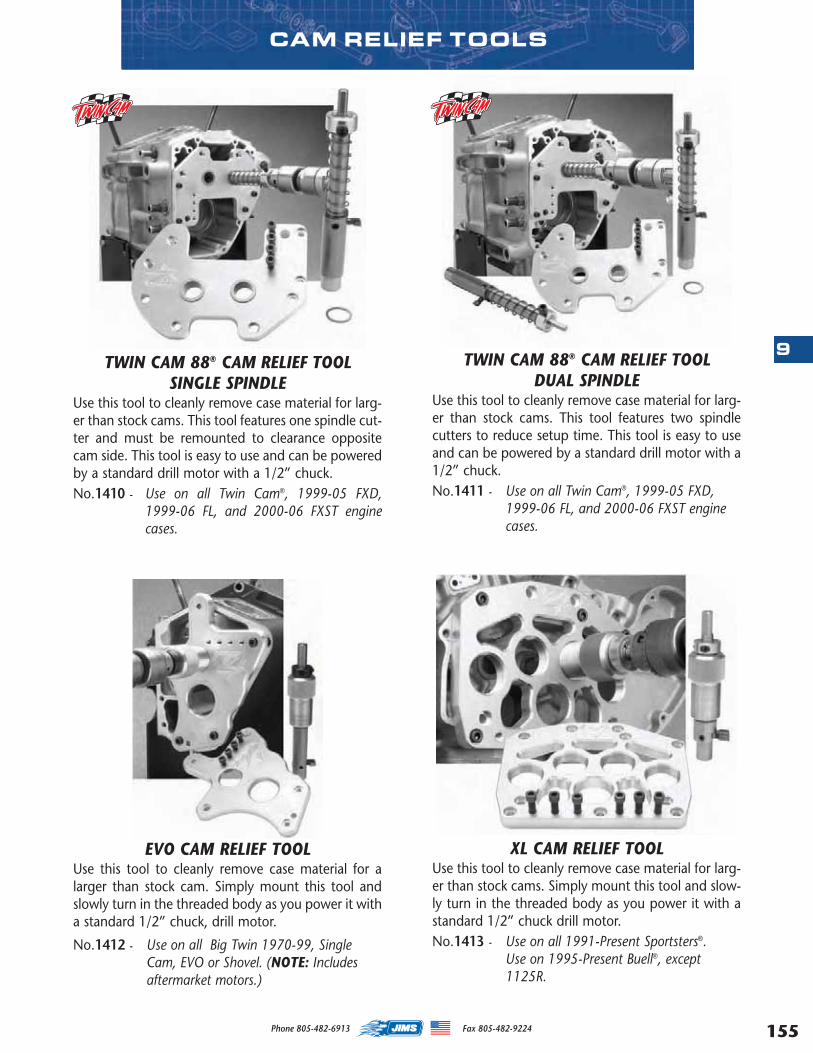
155
9
Phone 805-482-6913 Fax 805-482-9224
CAM RELIEF TOOLS
TWIN CAM 88® CAM RELIEF TOOL SINGLE SPINDLE
Use this tool to cleanly remove case material for larg-er than stock cams. This tool features one spindle cut-ter and must be remounted to clearance oppositecam side. This tool is easy to use and can be poweredby a standard drill motor with a 1/2” chuck.No.1410 - Use on all Twin Cam®, 1999-05 FXD,
1999-06 FL, and 2000-06 FXST enginecases.
TWIN CAM 88® CAM RELIEF TOOL DUAL SPINDLE
Use this tool to cleanly remove case material for larg-er than stock cams. This tool features two spindlecutters to reduce setup time. This tool is easy to useand can be powered by a standard drill motor with a1/2” chuck.No.1411 - Use on all Twin Cam®, 1999-05 FXD,
1999-06 FL, and 2000-06 FXST enginecases.
XL CAM RELIEF TOOLUse this tool to cleanly remove case material for larg-er than stock cams. Simply mount this tool and slow-ly turn in the threaded body as you power it with astandard 1/2” chuck drill motor. No.1413 - Use on all 1991-Present Sportsters®.
Use on 1995-Present Buell®, except1125R.
EVO CAM RELIEF TOOLUse this tool to cleanly remove case material for alarger than stock cam. Simply mount this tool andslowly turn in the threaded body as you power it witha standard 1/2” chuck, drill motor.
No.1412 - Use on all Big Twin 1970-99, SingleCam, EVO or Shovel. (NOTE: Includesaftermarket motors.)
MASTER 2013 CATALOG_JMS 2.qxp:Layout 1 8/2/12 8:29 PM Page 155
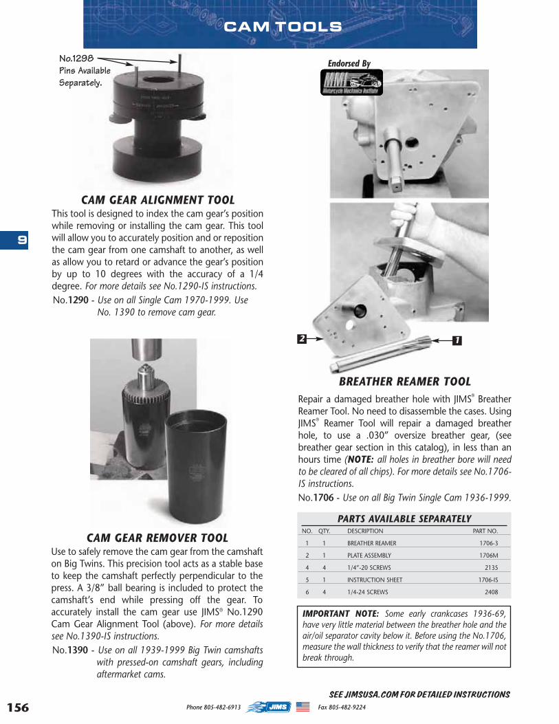
156
9
Phone 805-482-6913 Fax 805-482-9224
SEE JIMSUSA.COM FOR DETAILED INSTRUCTIONS
CAM TOOLS
CAM GEAR ALIGNMENT TOOLThis tool is designed to index the cam gear’s positionwhile removing or installing the cam gear. This toolwill allow you to accurately position and or repositionthe cam gear from one camshaft to another, as wellas allow you to retard or advance the gear’s positionby up to 10 degrees with the accuracy of a 1/4degree. For more details see No.1290-IS instructions. No.1290 - Use on all Single Cam 1970-1999. Use
No. 1390 to remove cam gear.
CAM GEAR REMOVER TOOLUse to safely remove the cam gear from the camshafton Big Twins. This precision tool acts as a stable baseto keep the camshaft perfectly perpendicular to thepress. A 3/8” ball bearing is included to protect thecamshaft’s end while pressing off the gear. Toaccurately install the cam gear use JIMS® No.1290Cam Gear Alignment Tool (above). For more detailssee No.1390-IS instructions. No.1390 - Use on all 1939-1999 Big Twin camshafts
with pressed-on camshaft gears, includingaftermarket cams.
PARTS AVAILABLE SEPARATELYNO. QTY. DESCRIPTION PART NO.
1 1 BREATHER REAMER 1706-3
2 1 PLATE ASSEMBLY 1706M
4 4 1/4”-20 SCREWS 2135
5 1 INSTRUCTION SHEET 1706-IS
6 4 1/4-24 SCREWS 2408
BREATHER REAMER TOOLRepair a damaged breather hole with JIMS® BreatherReamer Tool. No need to disassemble the cases. UsingJIMS® Reamer Tool will repair a damaged breatherhole, to use a .030” oversize breather gear, (seebreather gear section in this catalog), in less than anhours time (NOTE: all holes in breather bore will needto be cleared of all chips). For more details see No.1706-IS instructions. No.1706 - Use on all Big Twin Single Cam 1936-1999.
Endorsed By
IMPORTANT NOTE: Some early crankcases 1936-69,have very little material between the breather hole and theair/oil separator cavity below it. Before using the No.1706,measure the wall thickness to verify that the reamer will notbreak through.
12
No.1298Pins AvailableSeparately.
MASTER 2013 CATALOG_JMS 2.qxp:Layout 1 8/2/12 8:29 PM Page 156
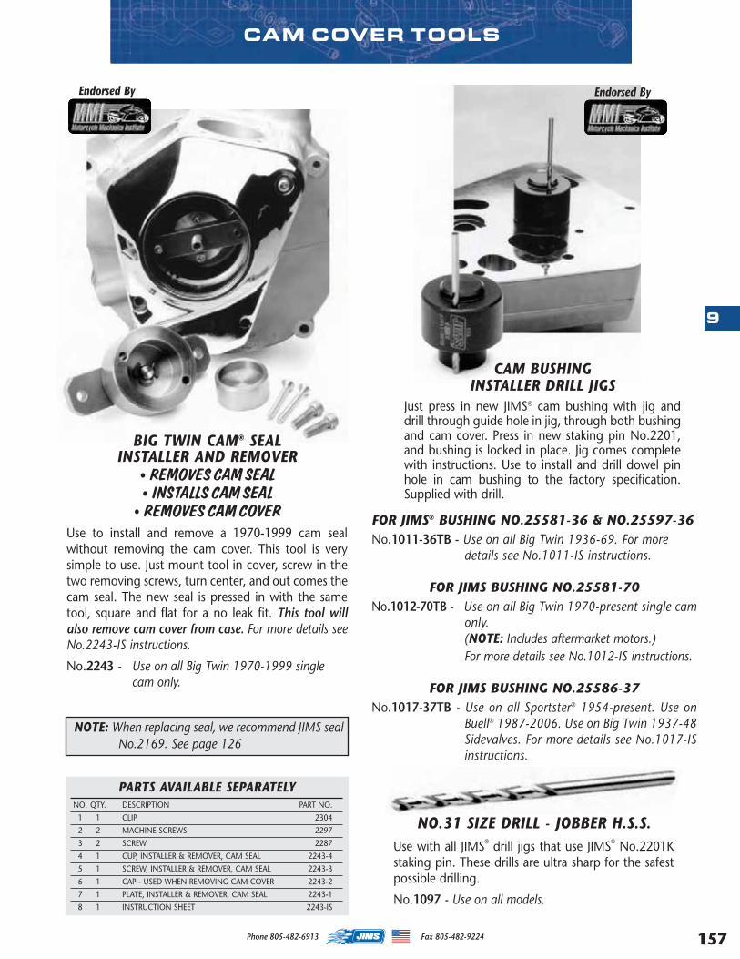
157
9
Phone 805-482-6913 Fax 805-482-9224
NO.31 SIZE DRILL - JOBBER H.S.S.Use with all JIMS® drill jigs that use JIMS® No.2201Kstaking pin. These drills are ultra sharp for the safestpossible drilling.
No.1097 - Use on all models.
PARTS AVAILABLE SEPARATELYNO. QTY. DESCRIPTION PART NO.
1 1 CLIP 2304
2 2 MACHINE SCREWS 2297
3 2 SCREW 2287
4 1 CUP, INSTALLER & REMOVER, CAM SEAL 2243-4
5 1 SCREW, INSTALLER & REMOVER, CAM SEAL 2243-3
6 1 CAP - USED WHEN REMOVING CAM COVER 2243-2
7 1 PLATE, INSTALLER & REMOVER, CAM SEAL 2243-1
8 1 INSTRUCTION SHEET 2243-IS
CAM COVER TOOLS
CAM BUSHING INSTALLER DRILL JIGS
Just press in new JIMS® cam bushing with jig anddrill through guide hole in jig, through both bushingand cam cover. Press in new staking pin No.2201,and bushing is locked in place. Jig comes completewith instructions. Use to install and drill dowel pinhole in cam bushing to the factory specification.Supplied with drill.
Endorsed By Endorsed By
NOTE: When replacing seal, we recommend JIMS sealNo.2169. See page 126
FOR JIMS® BUSHING NO.25581-36 & NO.25597-36No.1011-36TB - Use on all Big Twin 1936-69. For more
details see No.1011-IS instructions.
FOR JIMS BUSHING NO.25581-70No.1012-70TB - Use on all Big Twin 1970-present single cam
only.(NOTE: Includes aftermarket motors.)For more details see No.1012-IS instructions.
FOR JIMS BUSHING NO.25586-37No.1017-37TB - Use on all Sportster® 1954-present. Use on
Buell® 1987-2006. Use on Big Twin 1937-48Sidevalves. For more details see No.1017-ISinstructions.
BIG TWIN CAM® SEAL INSTALLER AND REMOVER
• REMOVES CAM SEAL• INSTALLS CAM SEAL
• REMOVES CAM COVERUse to install and remove a 1970-1999 cam sealwithout removing the cam cover. This tool is verysimple to use. Just mount tool in cover, screw in thetwo removing screws, turn center, and out comes thecam seal. The new seal is pressed in with the sametool, square and flat for a no leak fit. This tool willalso remove cam cover from case. For more details seeNo.2243-IS instructions.
No.2243 - Use on all Big Twin 1970-1999 singlecam only.
MASTER 2013 CATALOG_JMS 2.qxp:Layout 1 8/2/12 8:29 PM Page 157
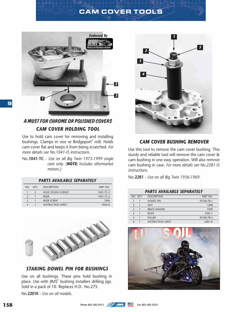
158
9
Phone 805-482-6913 Fax 805-482-9224
A MUST FOR CHROME OR POLISHED COVERSCAM COVER HOLDING TOOL
Use to hold cam cover for removing and installingbushings. Clamps in vice or Bridgeport® mill. Holdscam cover flat and keeps it from being scratched. Formore details see No.1041-IS instructions.
No.1041-TC - Use on all Big Twin 1973-1999 singlecam only. (NOTE: Includes aftermarketmotors.)
PARTS AVAILABLE SEPARATELYNO. QTY. DESCRIPTION PART NO.
1 2 HOLD DOWN SCREWS 1041-TC-3
2 1 RISER 1041-TC-2
3 1 RISER SCREW 1096
4 1 INSTRUCTION SHEET 1040-IS
STAKING DOWEL PIN FOR BUSHINGSUse on all bushings. These pins hold bushing inplace. Use with JIMS® bushing installers drilling jigs.Sold in a pack of 10. Replaces H.D.- No.275.
No.2201K - Use on all models.
CAM COVER BUSHING REMOVERUse this tool to remove the cam cover bushing. Thissturdy and reliable tool will remove the cam cover &cam bushing in one easy operation. Will also removecam bushing in case. For more details see No.2281-ISinstructions.
No.2281 - Use on all Big Twin 1936-1969.
CAM COVER TOOLS
PARTS AVAILABLE SEPARATELYNO. QTY. DESCRIPTION PART NO.
1 1 DOWEL PIN 95760-TB-1
2 1 NUT 1098
3 1 BRASS WASHER 1099
4 1 BODY 2281-1
5 1 PULLER 95760-TB-5
6 1 INSTRUCTION SHEET 2281-IS
Endorsed By 1
2
3
4
5
13
2
MASTER 2013 CATALOG_JMS 2.qxp:Layout 1 8/2/12 8:30 PM Page 158
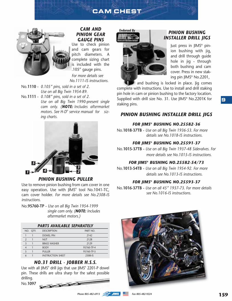
159
9
Phone 805-482-6913 Fax 805-482-9224
Just press in JIMS® pin-ion bushing with jig,and drill through guidehole in jig - throughboth bushing and camcover. Press in new stak-ing pin JIMS® No.2201,
PINION BUSHING PULLERUse to remove pinion bushing from cam cover in oneeasy operation. Use with JIMS® tool No.1041-TC,cam cover holder. For more details see No.2308-ISinstructions.
No.95760-TP - Use on all Big Twin 1954-1999 single cam only. (NOTE: Includesaftermarket motors.)
PARTS AVAILABLE SEPARATELYNO. QTY. DESCRIPTION PART NO.
1 1 DOWEL PIN 2142
2 1 NUT 2128
3 1 BRASS WASHER 2129
4 1 BODY 95760-TP-4
5 1 PULLER 95760-TP-5
6 1 INSTRUCTION SHEET 2308-IS
PINION BUSHING INSTALLER DRILL JIGS
FOR JIMS® BUSHING NO.25582-36No.1018-37TB - Use on all Big Twin 1936-53. For more
details see No.1018-IS instructions.
FOR JIMS® BUSHING NO.25591-37 No.1015-37TB - Use on all Big Twin 1937-48 Sidevalves. For
more details see No.1015-IS instructions.
FOR JIMS® BUSHING NO.25582-54/73 No.1013-54TB - Use on all Big Twin 1954-92. For more
details see No.1013-IS instructions.
FOR JIMS® BUSHING NO.25593-37 No.1016-37TB - Use on all 45” 1937-73. For more details
see No.1016-IS instructions.
NO.31 DRILL - JOBBER H.S.S.Use with all JIMS® drill jigs that use JIMS® 2201-P dowelpin. These drills are ultra sharp for the safest possibledrilling.No.1097
CAM CHEST
and bushing is locked in place. Jig comescomplete with instructions. Use to install and drill stakingpin hole in cam or pinion bushing to the factory location.Supplied with drill size No. 31. Use JIMS® No.2201K forstaking pins.
Endorsed By PINION BUSHING INSTALLER DRILL JIGS
1 23
4
5
No.1110 - 0.105” pins, sold in a set of 2.Use on all Big Twin 1954-89.
No.1111 - 0.108” pins, sold in a set of 2.Use on all Big Twin 1990-present singlecam only. (NOTE: Includes aftermarketmotors. See H-D® service manual for siz-ing charts.
CAM ANDPINION GEARGAUGE PINS
Use to check pinionand cam gears forpitch diameters. Acomplete sizing chartis included with the.105” gauge pins.
For more details see No.1111-IS instructions.
MASTER 2013 CATALOG_JMS 2.qxp:Layout 1 8/2/12 8:30 PM Page 159
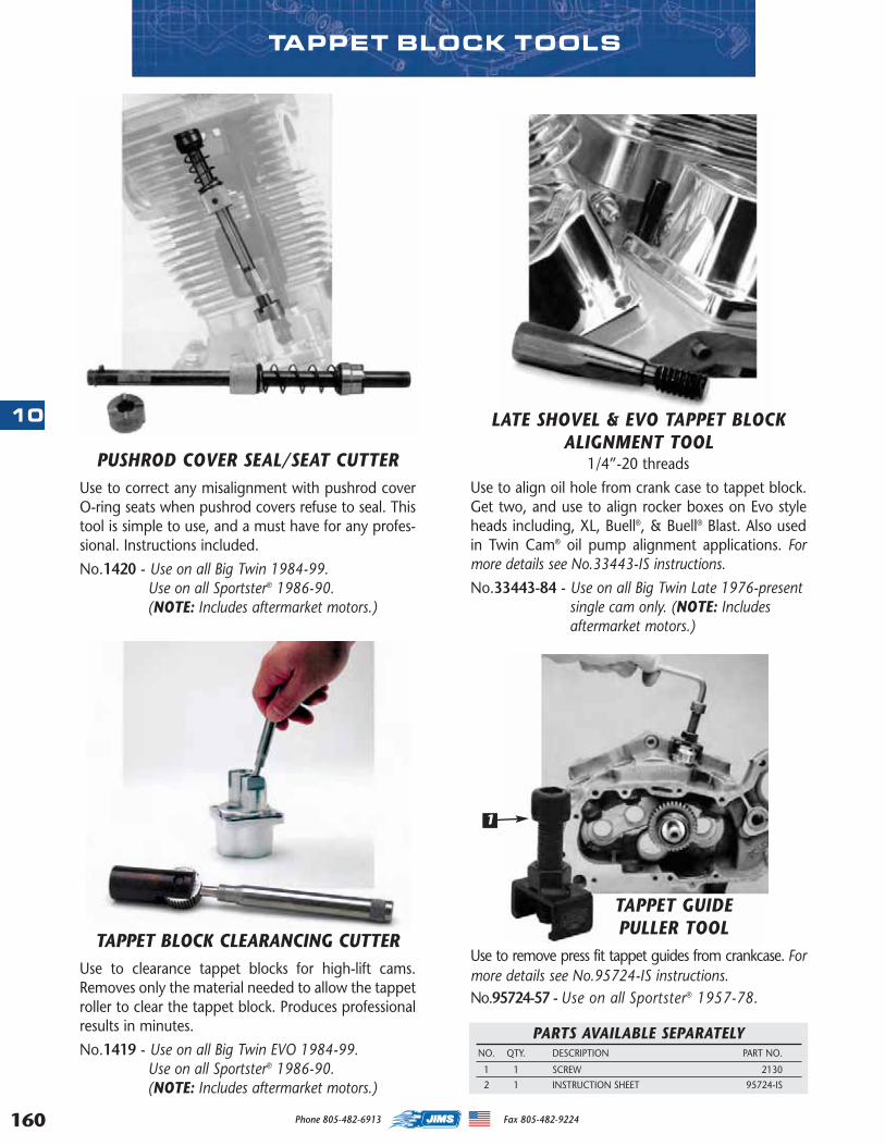
160
10
Phone 805-482-6913 Fax 805-482-9224
TAPPET GUIDE PULLER TOOL
Use to remove press fit tappet guides from crankcase. Formore details see No.95724-IS instructions.No.95724-57 - Use on all Sportster® 1957-78.
PARTS AVAILABLE SEPARATELYNO. QTY. DESCRIPTION PART NO.
1 1 SCREW 2130
2 1 INSTRUCTION SHEET 95724-IS
LATE SHOVEL & EVO TAPPET BLOCKALIGNMENT TOOL
1/4”-20 threads
Use to align oil hole from crank case to tappet block.Get two, and use to align rocker boxes on Evo styleheads including, XL, Buell®, & Buell® Blast. Also usedin Twin Cam® oil pump alignment applications. Formore details see No.33443-IS instructions.
No.33443-84 - Use on all Big Twin Late 1976-presentsingle cam only. (NOTE: Includesaftermarket motors.)
PUSHROD COVER SEAL/SEAT CUTTERUse to correct any misalignment with pushrod coverO-ring seats when pushrod covers refuse to seal. Thistool is simple to use, and a must have for any profes-sional. Instructions included.
No.1420 - Use on all Big Twin 1984-99.Use on all Sportster® 1986-90.(NOTE: Includes aftermarket motors.)
TAPPET BLOCK CLEARANCING CUTTERUse to clearance tappet blocks for high-lift cams.Removes only the material needed to allow the tappetroller to clear the tappet block. Produces professionalresults in minutes.
No.1419 - Use on all Big Twin EVO 1984-99.Use on all Sportster® 1986-90.(NOTE: Includes aftermarket motors.)
1
TAPPET BLOCK TOOLS
MASTER 2013 CATALOG_JMS 2.qxp:Layout 1 8/2/12 8:30 PM Page 160

161
10
Phone 805-482-6913 Fax 805-482-9224
ROD TOOLS
PARTS AVAILABLE SEPARATELYNO. QTY. DESCRIPTION PART NO.
1 1 CLAMP BASE 1284-1
2 2 HOLD DOWN NUT, T/C 1284-2
3 2 HOLD DOWN NUT, EVO 1284-3
4 2 THUMB SCREW 1286
5 1 INSTRUCTION SHEET 1284-IS
(Note use with rodsin or out of motor)
Use this kit to reamyour wrist pin bush-ings to H-D® specifi-cations. These ream-ers are made toexact tolerances,piloted to locatefrom the I.D. of yournewly replacedJIMS® wrist pin bushings. Reams are easy to use withtheir designed lead in taper at the start of each ream.Use JIMS® No.1284 Rod Clamp tool. For more detailssee No.1726-IS instructions. No.1726-3 - Use on Twin Cam® 1999-2005 FXD,
1999-2006 FL, & 2000-2006 FXST.No.1726-1 - Use on all Big Twins that use the late
diameter size wrist pins 1973 to present(NOTE: Includes aftermarket motors.)
No.1726-2 - Use on all Sportsters® 1957-present andBuell ® 1987-present, except 1125R.
NOTE: Some wrist pin bushings will need a smallamount of ball honing to give specified fit,see H-D® service manual for specifications.
WRIST PIN BUSHING REAMER TOOL
ROD ALIGNMENT TOOLUse to check rod straightness without removingrods from case. The alignment tool is 4-1/2”long. For more details see No.1010-IS instructions.
No.1158 - Use on JIMS® Twin Cam® Rods (.827”Wrist Pin)
No.1148 - Use on all Twin Cam® ‘A’ and ‘B’.(NOTE: Includes aftermarket motors.)(.927” Wrist Pin)
No.1010 - Use on all Big Twin single cam (.791”Wrist Pin)
Endorsed By
CONNECTING ROD BUSHING TOOL Use to remove and replace wrist pin bushings with-out removing connecting rods from crankcases. UseJIMS® No.1284 Rod Holder tool. For more details seeNo.95970-IS or No.1051-IS instructions.No.1051 - Use on all 1999-2006 FL, 1999-2005
FXD, & 2000-2006 FXST.No.95970-32C - Use on all single cam Big Twins, XL’s,
Buell’s, and 45’s.PARTS AVAILABLE SEPARATELY
NO. QTY. DESCRIPTION PART NO.
1 1 BOLT 2009
2 2 BRASS WASHER 2129
3 1 SLIDER 1051-1 OR 95970-32C-1
4 1 PULLER 1051-2 OR 95970-32C-2
5 1 BEARING 2010
6 1 COUPLING NUT 2011
7 1 INSTRUCTION SHEET 1051-IS & 95970-IS
ROD HOLDERTOOL
Use to keep con-necting rods in placeand eliminate twist-ing or bending ofthe connecting rodwhile reaming orhoning the wrist pinbushings. Workswell with JIMS ®
No.1051, 95970-32C wrist pin bush-ing tools, and JIMS® No.1726-1, 1726-2 and 1726-3wrist pin bushing reamers. For more details seeNo.1284-IS instructions. No.1284 - Use on all Twins and Buell®Blast.
Includes Twin Cam® ‘A’ and ‘B’.
MASTER 2013 CATALOG_JMS 2.qxp:Layout 1 8/2/12 8:30 PM Page 161
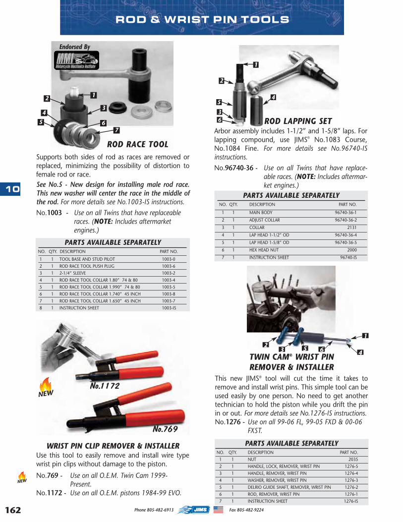
162
10
Phone 805-482-6913 Fax 805-482-9224
TWIN CAM® WRIST PIN REMOVER & INSTALLER
This new JIMS® tool will cut the time it takes toremove and install wrist pins. This simple tool can beused easily by one person. No need to get anothertechnician to hold the piston while you drift the pinin or out. For more details see No.1276-IS instructions. No.1276 - Use on all 99-06 FL, 99-05 FXD & 00-06
FXST.
12
3 45
PARTS AVAILABLE SEPARATELYNO. QTY. DESCRIPTION PART NO.
1 1 NUT 2035
2 1 HANDLE, LOCK, REMOVER, WRIST PIN 1276-5
3 1 HANDLE, REMOVER, WRIST PIN 1276-4
4 1 WASHER, REMOVER, WRIST PIN 1276-3
5 1 DELRIO GUIDE SHAFT, REMOVER, WRIST PIN 1276-2
6 1 ROD, REMOVER, WRIST PIN 1276-1
7 1 INSTRUCTION SHEET 1276-IS
ROD & WRIST PIN TOOLS
WRIST PIN CLIP REMOVER & INSTALLERUse this tool to easily remove and install wire typewrist pin clips without damage to the piston.
No.769 - Use on all O.E.M. Twin Cam 1999-Present.
No.1172 - Use on all O.E.M. pistons 1984-99 EVO.
6
No.769
No.1172
NEW
NEW
PARTS AVAILABLE SEPARATELYNO. QTY. DESCRIPTION PART NO.
1 1 TOOL BASE AND STUD PILOT 1003-0
2 1 ROD RACE TOOL PUSH PLUG 1003-6
3 1 2-1/4” SLEEVE 1003-2
4 1 ROD RACE TOOL COLLAR 1.80” 74 & 80 1003-4
5 1 ROD RACE TOOL COLLAR 1.990” 74 & 80 1003-5
6 1 ROD RACE TOOL COLLAR 1.740” 45 INCH 1003-8
7 1 ROD RACE TOOL COLLAR 1.650” 45 INCH 1003-7
8 1 INSTRUCTION SHEET 1003-IS
ROD LAPPING SETArbor assembly includes 1-1/2” and 1-5/8” laps. Forlapping compound, use JIMS® No.1083 Course,No.1084 Fine. For more details see No.96740-ISinstructions.
No.96740-36 - Use on all Twins that have replace-able races. (NOTE: Includes aftermar-ket engines.)
PARTS AVAILABLE SEPARATELYNO. QTY. DESCRIPTION PART NO.
1 1 MAIN BODY 96740-36-1
2 1 ADJUST COLLAR 96740-36-2
3 1 COLLAR 2131
4 1 LAP HEAD 1-1/2” OD 96740-36-4
5 1 LAP HEAD 1-5/8” OD 96740-36-5
6 1 HEX HEAD NUT 2000
7 1 INSTRUCTION SHEET 96740-IS
ROD RACE TOOLSupports both sides of rod as races are removed orreplaced, minimizing the possibility of distortion tofemale rod or race. See No.5 - New design for installing male rod race.This new washer will center the race in the middle ofthe rod. For more details see No.1003-IS instructions.
No.1003 - Use on all Twins that have replaceableraces. (NOTE: Includes aftermarketengines.)
Endorsed By
12
34
5 67
1
2
3
45
6
MASTER 2013 CATALOG_JMS 2.qxp:Layout 1 8/2/12 8:30 PM Page 162
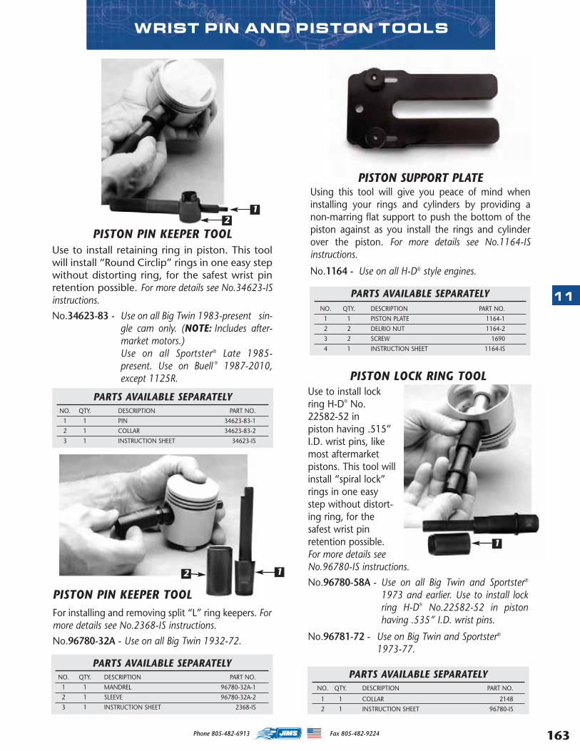
163
11
Phone 805-482-6913 Fax 805-482-9224
PISTON LOCK RING TOOLUse to install lockring H-D® No.22582-52 in piston having .515”I.D. wrist pins, likemost aftermarketpistons. This tool willinstall “spiral lock”rings in one easystep without distort-ing ring, for thesafest wrist pinretention possible.For more details seeNo.96780-IS instructions.
No.96780-58A - Use on all Big Twin and Sportster®
1973 and earlier. Use to install lockring H-D® No.22582-52 in pistonhaving .535” I.D. wrist pins.
No.96781-72 - Use on Big Twin and Sportster®
1973-77.
WRIST PIN AND PISTON TOOLS
PISTON SUPPORT PLATE Using this tool will give you peace of mind wheninstalling your rings and cylinders by providing anon-marring flat support to push the bottom of thepiston against as you install the rings and cylinderover the piston. For more details see No.1164-ISinstructions.
No.1164 - Use on all H-D® style engines.
PARTS AVAILABLE SEPARATELYNO. QTY. DESCRIPTION PART NO.
1 1 PISTON PLATE 1164-1
2 2 DELRIO NUT 1164-2
3 2 SCREW 1690
4 1 INSTRUCTION SHEET 1164-IS
PARTS AVAILABLE SEPARATELYNO. QTY. DESCRIPTION PART NO.
1 1 PIN 34623-83-1
2 1 COLLAR 34623-83-2
3 1 INSTRUCTION SHEET 34623-IS
PISTON PIN KEEPER TOOLUse to install retaining ring in piston. This toolwill install “Round Circlip” rings in one easy stepwithout distorting ring, for the safest wrist pinretention possible. For more details see No.34623-ISinstructions.
No.34623-83 - Use on all Big Twin 1983-present sin-gle cam only. (NOTE: Includes after-market motors.)Use on all Sportster® Late 1985-present. Use on Buell ® 1987-2010,except 1125R.
12
1
PISTON PIN KEEPER TOOLFor installing and removing split “L” ring keepers. Formore details see No.2368-IS instructions.
No.96780-32A - Use on all Big Twin 1932-72.
PARTS AVAILABLE SEPARATELYNO. QTY. DESCRIPTION PART NO.
1 1 MANDREL 96780-32A-1
2 1 SLEEVE 96780-32A-2
3 1 INSTRUCTION SHEET 2368-IS
2 1
PARTS AVAILABLE SEPARATELYNO. QTY. DESCRIPTION PART NO.
1 1 COLLAR 2148
2 1 INSTRUCTION SHEET 96780-IS
MASTER 2013 CATALOG_JMS 2.qxp:Layout 1 8/2/12 8:30 PM Page 163
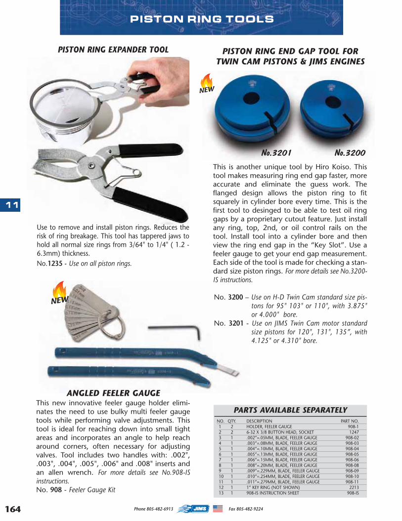
164
11
Phone 805-482-6913 Fax 805-482-9224
PISTON RING TOOLS
PISTON RING EXPANDER TOOL
Use to remove and install piston rings. Reduces therisk of ring breakage. This tool has tappered jaws tohold all normal size rings from 3/64" to 1/4" ( 1.2 -6.3mm) thickness. No.1235 - Use on all piston rings.
PISTON RING END GAP TOOL FOR TWIN CAM PISTONS & JIMS ENGINES
This is another unique tool by Hiro Koiso. Thistool makes measuring ring end gap faster, moreaccurate and eliminate the guess work. Theflanged design allows the piston ring to fitsquarely in cylinder bore every time. This is thefirst tool to desinged to be able to test oil ringgaps by a proprietary cutout feature. Just installany ring, top, 2nd, or oil control rails on thetool. Install tool into a cylinder bore and thenview the ring end gap in the “Key Slot”. Use afeeler gauge to get your end gap measurement.Each side of the tool is made for checking a stan-dard size piston rings. For more details see No.3200-IS instructions.
No. 3200 – Use on H-D Twin Cam standard size pis-tons for 95" 103" or 110", with 3.875"or 4.000" bore.
No. 3201 - Use on JIMS Twin Cam motor standardsize pistons for 120", 131", 135”, with4.125" or 4.310" bore.
NEW
No.3200No.3201
ANGLED FEELER GAUGEThis new innovative feeler gauge holder elimi-nates the need to use bulky multi feeler gaugetools while performing valve adjustments. Thistool is ideal for reaching down into small tightareas and incorporates an angle to help reacharound corners, often necessary for adjustingvalves. Tool includes two handles with: .002",.003", .004", .005", .006" and .008" inserts andan allen wrench. For more details see No.908-ISinstructions.No. 908 - Feeler Gauge Kit
NEW
PARTS AVAILABLE SEPARATELYNO. QTY. DESCRIPTION PART NO.1 2 HOLDER, FEELER GAUGE 908-12 2 6-32 X 3/8 BUTTON HEAD, SOCKET 12473 1 .002”=.05MM, BLADE, FEELER GAUGE 908-024 1 .003”=.08MM, BLADE, FEELER GAUGE 908-035 1 .004”=.10MM, BLADE, FEELER GAUGE 908-046 1 .005”=.13MM, BLADE, FEELER GAUGE 908-057 1 .006”=.15MM, BLADE, FEELER GAUGE 908-068 1 .008”=.20MM, BLADE, FEELER GAUGE 908-089 1 .009”=.229MM, BLADE, FEELER GAUGE 908-09 10 1 .010”=.254MM, BLADE, FEELER GAUGE 908-1011 1 .011”=.279MM, BLADE, FEELER GAUGE 908-1112 1 1” KEY RING (NOT SHOWN) 221313 1 908-IS INSTRUCTION SHEET 908-IS
MASTER 2013 CATALOG_JMS 2.qxp:Layout 1 8/2/12 8:30 PM Page 164
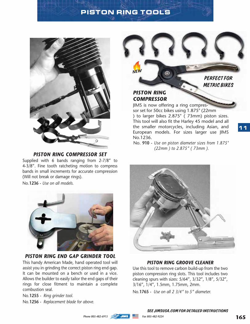
165
11
Phone 805-482-6913 Fax 805-482-9224
SEE JIMSUSA.COM FOR DETAILED INSTRUCTIONS
PISTON RING GROOVE CLEANERUse this tool to remove carbon build-up from the twopiston compression ring slots. This tool includes twocleaning spurs with sizes: 5/64”, 3/32”, 1/8”, 5/32”,3/16”, 1/4”, 1.5mm, 1.75mm, 2mm.
No.1765 - Use on all 2 3/4” to 5” diameter.
PISTON RING END GAP GRINDER TOOLThis handy American Made, hand operated tool willassist you in grinding the correct piston ring end gap.It can be mounted on a bench or used in a vice.Allows the builder to easily tailor the end gaps of theirrings for close fitment to maintain a completecombustion seal. No.1255 - Ring grinder tool.No.1256 - Replacement blade for above.
PISTON RING COMPRESSOR SETSupplied with 6 bands ranging from 2-7/8” to4-3/8”. Fine tooth ratcheting motion to compressbands in small increments for accurate compression(Will not break or damage rings).No.1236 - Use on all models.
PISTON RING TOOLS
PISTON RINGCOMPRESSORJIMS is now offering a ring compres-sor set for 50cc bikes using 1.875" (22mm) to larger bikes 2.875" ( 73mm) piston sizes.This tool will also fit the Harley 45 model and allthe smaller motorcycles, including Asian, andEuropean models. For sizes larger use JIMSNo.1236.No. 910 - Use on piston diameter sizes from 1.875"
(22mm ) to 2.875” ( 73mm ).
NEW
PERFECT FORMETRIC BIKES
MASTER 2013 CATALOG_JMS 2.qxp:Layout 1 8/2/12 8:30 PM Page 165
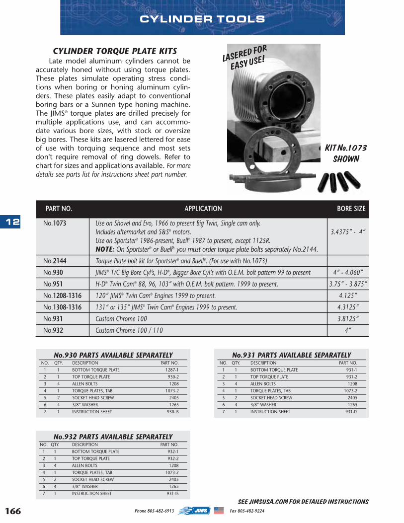
166
12
Phone 805-482-6913 Fax 805-482-9224
LASERED FOR
EASY USE!
CYLINDER TOOLS
CYLINDER TORQUE PLATE KITS Late model aluminum cylinders cannot be
accurately honed without using torque plates.These plates simulate operating stress condi-tions when boring or honing aluminum cylin-ders. These plates easily adapt to conventionalboring bars or a Sunnen type honing machine.The JIMS® torque plates are drilled precisely formultiple applications use, and can accommo-date various bore sizes, with stock or oversizebig bores. These kits are lasered lettered for easeof use with torquing sequence and most setsdon't require removal of ring dowels. Refer tochart for sizes and applications available. For moredetails see parts list for instructions sheet part number.
KIT No.1073SHOWN
No.931 PARTS AVAILABLE SEPARATELYNO. QTY. DESCRIPTION PART NO.
1 1 BOTTOM TORQUE PLATE 931-1
2 1 TOP TORQUE PLATE 931-2
3 4 ALLEN BOLTS 1208
4 1 TORQUE PLATES, TAB 1073-2
5 2 SOCKET HEAD SCREW 2405
6 4 3/8” WASHER 1265
7 1 INSTRUCTION SHEET 931-IS
No.932 PARTS AVAILABLE SEPARATELYNO. QTY. DESCRIPTION PART NO.
1 1 BOTTOM TORQUE PLATE 932-1
2 1 TOP TORQUE PLATE 932-2
3 4 ALLEN BOLTS 1208
4 1 TORQUE PLATES, TAB 1073-2
5 2 SOCKET HEAD SCREW 2405
6 4 3/8” WASHER 1265
7 1 INSTRUCTION SHEET 931-IS
No.1073 Use on Shovel and Evo, 1966 to present Big Twin, Single cam only. Includes aftermarket and S&S® motors. 3.4375” - 4”Use on Sportster® 1986-present, Buell® 1987 to present, except 1125R. NOTE: On Sportster® or Buell® you must order torque plate bolts separately No.2144.
No.2144 Torque Plate bolt kit for Sportster® and Buell®. (For use with No.1073)
No.930 JIMS® T/C Big Bore Cyl’s, H-D®, Bigger Bore Cyl’s with O.E.M. bolt pattern 99 to present 4” - 4.060”
No.951 H-D® Twin Cam® 88, 96, 103” with O.E.M. bolt pattern. 1999 to present. 3.75” - 3.875”
No.1208-1316 120” JIMS® Twin Cam® Engines 1999 to present. 4.125”
No.1308-1316 131” or 135” JIMS® Twin Cam® Engines 1999 to present. 4.3125”
No.931 Custom Chrome 100 3.8125”
No.932 Custom Chrome 100 / 110 4”
PART NO. APPLICATION BORE SIZE
No.930 PARTS AVAILABLE SEPARATELYNO. QTY. DESCRIPTION PART NO.
1 1 BOTTOM TORQUE PLATE 1287-1
2 1 TOP TORQUE PLATE 930-2
3 4 ALLEN BOLTS 1208
4 1 TORQUE PLATES, TAB 1073-2
5 2 SOCKET HEAD SCREW 2405
6 4 3/8” WASHER 1265
7 1 INSTRUCTION SHEET 930-IS
SEE JIMSUSA.COM FOR DETAILED INSTRUCTIONS
MASTER 2013 CATALOG_JMS 2.qxp:Layout 1 8/2/12 8:30 PM Page 166
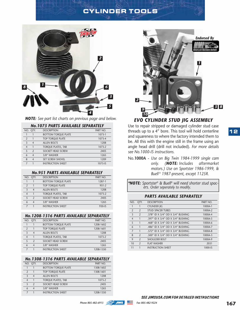
167
12
Phone 805-482-6913 Fax 805-482-9224
1
2
3
4
5
6
CYLINDER TOOLS
8
EVO CYLINDER STUD JIG ASSEMBLYUse to repair stripped or damaged cylinder stud casethreads up to a 4” bore. This tool will hold centerlineand squareness to where the factory intended them tobe. All this with the engine still in the frame using anangle head drill (drill not included). For more detailssee No.1000-IS instructions.
No.1000A - Use on Big Twin 1984-1999 single camonly. (NOTE: Includes aftermarketmotors.) Use on Sportster 1986-1999, &Buell ® 1987-present, except 1125R.
PARTS AVAILABLE SEPARATELYNO. QTY. DESCRIPTION PART NO.
1 1 CYLINDER JIG 1000A-1
2 2 STUD SPACER TUBES 1000A-2
3 2 .378” ID X 3/4” OD X 3/4” BUSHING 1000A-4
4 1 .397” ID X 3/4” OD X 3/4” BUSHING 1000A-5
5 1 .468” ID X 3/4” OD X 3/4” BUSHING 1000A-6
6 1 .486” ID X 3/4” OD X 3/4” BUSHING 1000A-7
7 1 .572” ID X 3/4” OD X 3/4” BUSHING 1000A-8
8 2 .500” ID X 3/4” OD X 3/4” BUSHING 1000A-3
9 2 SHOULDER BOLT 1000A-9
10 2 FLAT WASHER 2031
11 1 INSTRUCTION SHEET 1000-IS
Endorsed By
*NOTE: Sportster® & Buell® will need shorter stud spac-ers. Order seperately to modify.
1
2
3 8910
NOTE: See part list charts on previous page and below.
No.1073 PARTS AVAILABLE SEPARATELYNO. QTY. DESCRIPTION PART NO.
1 1 BOTTOM TORQUE PLATE 1073-1
2 1 TOP TORQUE PLATE 1073-4
3 4 ALLEN BOLTS 1208
4 1 TORQUE PLATES, TAB 1073-2
5 2 SOCKET HEAD SCREW 2405
6 4 3/8” WASHER 1265
8 4 SET SCREW SHOVEL 1209
7 1 INSTRUCTION SHEET 1073-IS
No.1208-1316 PARTS AVAILABLE SEPARATELYNO. QTY. DESCRIPTION PART NO.
1 1 BOTTOM TORQUE PLATE 1208-1602
2 1 TOP TORQUE PLATE 1208-1601
3 4 ALLEN BOLTS 1208
4 1 TORQUE PLATES, TAB 1073-2
5 2 SOCKET HEAD SCREW 2405
6 4 3/8” WASHER 1265
7 1 INSTRUCTION SHEET 1208-1350
No.1308-1316 PARTS AVAILABLE SEPARATELYNO. QTY. DESCRIPTION PART NO.
1 1 BOTTOM TORQUE PLATE 1308-1602
2 1 TOP TORQUE PLATE 1308-1601
3 4 ALLEN BOLTS 1208
4 1 TORQUE PLATES, TAB 1073-2
5 2 SOCKET HEAD SCREW 2405
6 4 3/8” WASHER 1265
7 1 INSTRUCTION SHEET 1208-1350
No.951 PARTS AVAILABLE SEPARATELYNO. QTY. DESCRIPTION PART NO.
1 1 BOTTOM TORQUE PLATE 1287-1
2 1 TOP TORQUE PLATE 951-2
3 4 ALLEN BOLTS 1208
4 1 TORQUE PLATES, TAB 1073-2
5 2 SOCKET HEAD SCREW 2405
6 4 3/8” WASHER 1265
7 1 INSTRUCTION SHEET 930-IS
SEE JIMSUSA.COM FOR DETAILED INSTRUCTIONS
MASTER 2013 CATALOG_JMS 2.qxp:Layout 1 8/2/12 8:30 PM Page 167
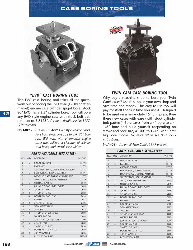
168
13
Phone 805-482-6913 Fax 805-482-9224
TWIN CAM CASE BORING TOOLWhy pay a machine shop to bore your TwinCam® cases? Use this tool in your own shop andsave time and money. This easy to use tool willpay for itself the first time you use it. Designedto be used on a heavy-duty 15” drill press. Borethese new cases with ease (with stock cylinderbolt pattern). Bore cases from a 4” bore to a 4-1/8” bore and build yourself (depending onstroke and bore size) a 100” to 124” Twin Cam®
big bore motor. For more details see No.1177-ISinstructions.
No.1408 - Use on all Twin Cam®, 1999-present.
MOUNTING PLATE
BASE PLATE
ALIGNMENT PLATE
BORING HEAD, BORING ASSEMBLY
LOCATING PLATE, BORING ASSEMBLY
SUPPORT PLATE, BORING ASSEMBLY
TOOL, PLATE, PRIMARY SIDE
SHIELDED BEARING
PULL OUT DOWEL, 1/2" x 3-1/2"
3/8-16" x 1" SHCS
1/4-20" x 1" SHCS
DOWEL PIN, 1/4" x 3/4"
BUSHING
5/16-18" x 1" SHCS
T-PIN, Ø3/8" SHANK
TOOL BIT
1/4-28" x 1/2" SET SCREW
WASHER, 1/4", SAE
5/16-18" x 1-3/4" SET SCREW
5/16-18" JAM NUT
1/4-20" x 1/2, BHCS
DOWEL PIN 1/2" x 3-1/2"
3/8" AN WASHER
INSTRUCTION SHEET
1177-1
1177-2
1177-3
1177-4
1177-5
1177-6
1408-1
8149
1685
1686
2133
8093
1681
2405
1687
1688
1689
1683
1200
1222
8090
1680
1265
1177-IS
1
2
3
4
5
6
7
8
9
10
11
12
13
14
15
16
17
18
19
20
21
22
23
24
1
1
1
1
1
1
1
1
1
9
4
4
2
3
1
2
6
2
1
1
1
3
3
1
PARTS AVAILABLE SEPARATELYNO. QTY. DESCRIPTION PART NO.
MOUNTING PLATE
BASE PLATE
ALIGNMENT PLATE, CASE BORING TOOL, EVO
BORING HEAD, BORING ASSEMBLY
LOCATING PLATE, BORING ASSEMBLY, EVO
SUPPORT PLATE, BORING ASSEMBLY
SHIELDED BEARING
PULL OUT DOWEL, 1/2" x 3-1/2"
3/8-16" x 1" SHCS
1/4-20" x 1" SHCS
DOWEL PIN, 1/4" x 3/4"
BUSHING
5/16-18" x 1" SHCS
T-PIN, Ø3/8" SHANK
TOOL BIT
1/4-28" x 1/2" SET SCREW
WASHER, 1/4", SAE
5/16-18" x 1-3/4" SET SCREW
5/16-18" NUT
1/4-20" x 1/2", BHCS
DOWEL PIN 1/2" x 3-1/2"
3/8" AN WASHER
INSTRUCTION SHEET
1177-1
1177-2
1177-3
1177-4
1177-5
1177-6
8149
1685
1686
2133
8093
1681
2405
1687
1688
1689
1683
1200
1222
8090
1680
1265
1177-IS
1
2
3
4
5
6
7
8
9
10
11
12
13
14
15
16
17
18
19
20
21
22
23
1
1
1
1
1
1
1
1
6
2
4
2
3
2
6
2
1
1
1
1
3
3
1
PARTS AVAILABLE SEPARATELYNO. QTY. DESCRIPTION PART NO.
CASE BORING TOOLS
“EVO” CASE BORING TOOLThis EVO case boring tool takes all the guess-work out of boring the EVO style (H-D® or after-market) engine case cylinder spigot bore. Stock80” EVO has a 3.5” cylinder bore. Tool will boreany EVO style engine case with stock bolt pat-tern, up to 3.8125”. For more details see No.1177-IS instructions.
No.1409 - Use on 1984-99 EVO style engine cases.Bore from stock bore size to 3.8125” boresize. Will work with aftermarket enginecases that utilize stock location of cylinderstud holes, and overall case widths.
MASTER 2013 CATALOG_JMS 2.qxp:Layout 1 8/2/12 8:30 PM Page 168
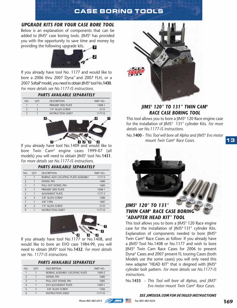
169
13
Phone 805-482-6913 Fax 805-482-9224
CASE BORING TOOLS
UPGRADE KITS FOR YOUR CASE BORE TOOLBelow is an explanation of components that can beadded to JIMS® case boring tools. JIMS® has providedyou with the opportunity to save time and money byproviding the following upgrade kits.
If you already have tool No.1177 or No.1408, andwould like to bore an EVO case 1984-99, you willneed to obtain JIMS® tool No.1432. For more detailssee No. 1177-IS instructions.
PARTS AVAILABLE SEPARATELYNO. QTY. DESCRIPTION PART NO.
1 1 BORING ASSY LOCATING PLATE ASSEMBLY 1177-5
2 1 DOWEL PIN 1680
3 1 PULL OUT DOWEL PIN 1685
4 1 PRIMARY SIDE PLATE 1408-1
5 1 ALIGNMENT PLATE 1177-3
6 3 3/8" ALLEN SCREW 1686
7 1 3/8" T-PIN 1687
8 2 1/4" ALLEN SCREW 2133
9 1 INSTRUCTION SHEET 1177-IS
PARTS AVAILABLE SEPARATELYNO. QTY. DESCRIPTION PART NO.
1 1 BORING ASSEMBLY LOCATING PLATE 1409-2
2 1 DOWEL PIN 1680
3 1 PULL OUT DOWEL PIN 1685
4 1 EVO ALIGNMENT PLATE 1409-1
5 3 3/8" ALLEN SCREW 1306
6 1 INSTRUCTION SHEET 1177-IS
PARTS AVAILABLE SEPARATELYNO. QTY. DESCRIPTION PART NO.
1 1 PRIMARY SIDE PLATE 1408-1
2 2 1/4" ALLEN SCREW 2133
3 1 INSTRUCTION SHEET 1177-IS
If you already have tool No.1409 and would like tobore Twin Cam® engine cases 1999-07 (allmodels) you will need to obtain JIMS® tool No.1431.For more details see No.1177-IS instructions.
If you already have tool No. 1177 and would like tobore a 2006 thru 2007 Dyna™ and 2007 FLH, or a2007 Softail® model, you need to obtain JIMS® tool No.1430.For more details see No.1177-IS instructions.
5 4 1
7 3 2 8 6
5
1
2
2
1
4 3
JIMS® 120” TO 131” TWIN CAM®
RACE CASE BORING TOOLThis tool allows you to bore a JIMS® 120 Race engine casefor the installation of JIMS® 131" cylinder Kits. For moredetails see No.1177-IS instructions.
No.1400 - This Tool will bore all Alpha and JIMS® Evo motormount Twin Cam® Race Cases.
SEE JIMSUSA.COM FOR DETAILED INSTRUCTIONS
JIMS® 120" TO 131"TWIN CAM® RACE CASE BORING"ADAPTER HEAD KIT" TOOL This tool allows you to bore a JIMS® 120 Race enginecase for the installation of JIMS® 131" cylinder Kits.Explanation of components needed to bore JIMS®
Twin Cam® Race Cases as follow: If you already havea JIMS® Tool No.1408 or No.1177 and wish to boreJIMS® Twin Cam Race Cases for 2006 to presentDyna® Cases and 2007 present FL touring Cases (bothModels use the some cases) you will only need thisnew adapter "HEAD KIT" that is deigned with JIMS®
cylinder bolt pattern. For more details see No.1177-ISinstructions.No.1433 - This Tool will bore all Alphas, and JIMS®
Evo motor mount Twin Cam® Race Cases.
MASTER 2013 CATALOG_JMS 2.qxp:Layout 1 8/2/12 8:30 PM Page 169
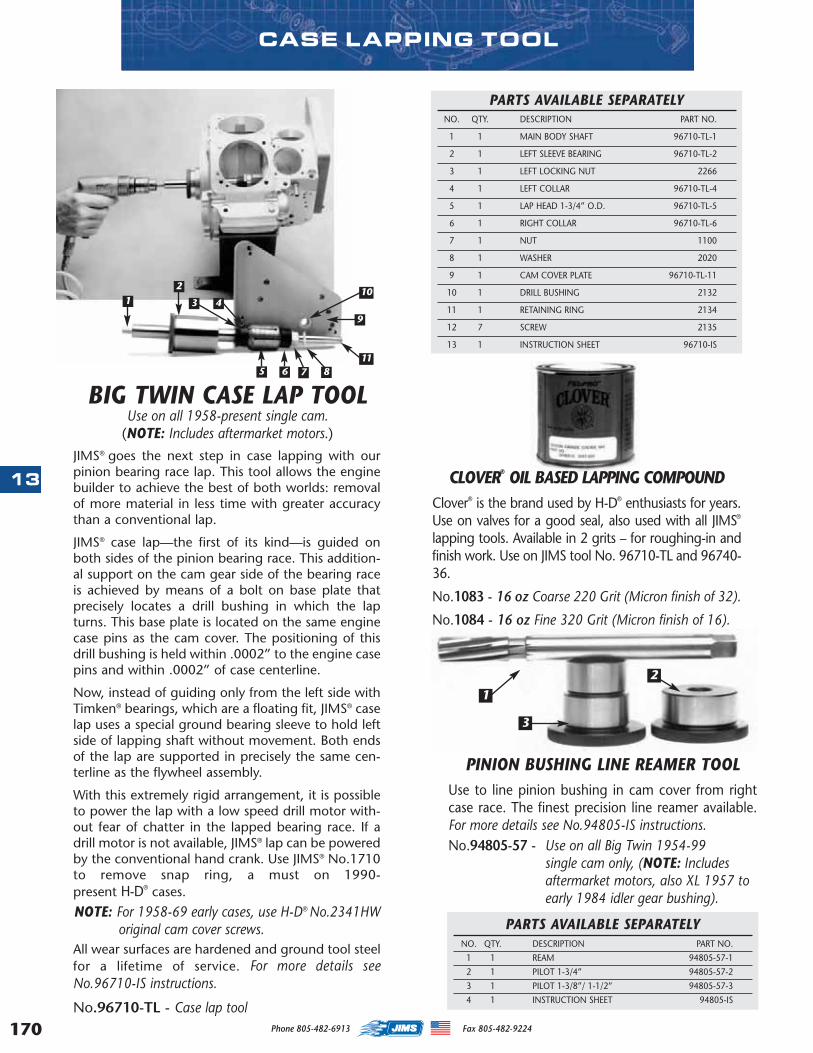
170
13
Phone 805-482-6913 Fax 805-482-9224
JIMS® goes the next step in case lapping with ourpinion bearing race lap. This tool allows the enginebuilder to achieve the best of both worlds: removalof more material in less time with greater accuracythan a conventional lap.
JIMS® case lap—the first of its kind— is guided onboth sides of the pinion bearing race. This addition-al support on the cam gear side of the bearing raceis achieved by means of a bolt on base plate thatprecisely locates a drill bushing in which the lapturns. This base plate is located on the same enginecase pins as the cam cover. The positioning of thisdrill bushing is held within .0002” to the engine casepins and within .0002” of case centerline.
Now, instead of guiding only from the left side withTimken® bearings, which are a floating fit, JIMS® caselap uses a special ground bearing sleeve to hold leftside of lapping shaft without movement. Both endsof the lap are supported in precisely the same cen-terline as the flywheel assembly.
With this extremely rigid arrangement, it is possibleto power the lap with a low speed drill motor with-out fear of chatter in the lapped bearing race. If adrill motor is not available, JIMS® lap can be poweredby the conventional hand crank. Use JIMS® No.1710to remove snap ring, a must on 1990-present H-D® cases.
NOTE: For 1958-69 early cases, use H-D® No.2341HWoriginal cam cover screws.
All wear surfaces are hardened and ground tool steelfor a lifetime of service. For more details seeNo.96710-IS instructions.
No.96710-TL - Case lap tool
BIG TWIN CASE LAP TOOLUse on all 1958-present single cam.
(NOTE: Includes aftermarket motors.)
PARTS AVAILABLE SEPARATELYNO. QTY. DESCRIPTION PART NO.
1 1 MAIN BODY SHAFT 96710-TL-1
2 1 LEFT SLEEVE BEARING 96710-TL-2
3 1 LEFT LOCKING NUT 2266
4 1 LEFT COLLAR 96710-TL-4
5 1 LAP HEAD 1-3/4” O.D. 96710-TL-5
6 1 RIGHT COLLAR 96710-TL-6
7 1 NUT 1100
8 1 WASHER 2020
9 1 CAM COVER PLATE 96710-TL-11
10 1 DRILL BUSHING 2132
11 1 RETAINING RING 2134
12 7 SCREW 2135
13 1 INSTRUCTION SHEET 96710-IS
CASE LAPPING TOOL
CLOVER® OIL BASED LAPPING COMPOUNDClover® is the brand used by H-D® enthusiasts for years.Use on valves for a good seal, also used with all JIMS®
lapping tools. Available in 2 grits – for roughing-in andfinish work. Use on JIMS tool No. 96710-TL and 96740-36.
No.1083 - 16 oz Coarse 220 Grit (Micron finish of 32).
No.1084 - 16 oz Fine 320 Grit (Micron finish of 16).
1
2
3 4
5 6 7 8
9
10
11
PINION BUSHING LINE REAMER TOOLUse to line pinion bushing in cam cover from rightcase race. The finest precision line reamer available.For more details see No.94805-IS instructions.No.94805-57 - Use on all Big Twin 1954-99
single cam only, (NOTE: Includesaftermarket motors, also XL 1957 toearly 1984 idler gear bushing).
PARTS AVAILABLE SEPARATELYNO. QTY. DESCRIPTION PART NO.
1 1 REAM 94805-57-1
2 1 PILOT 1-3/4” 94805-57-2
3 1 PILOT 1-3/8”/ 1-1/2” 94805-57-3
4 1 INSTRUCTION SHEET 94805-IS
1
2
3
MASTER 2013 CATALOG_JMS 2.qxp:Layout 1 8/2/12 8:30 PM Page 170
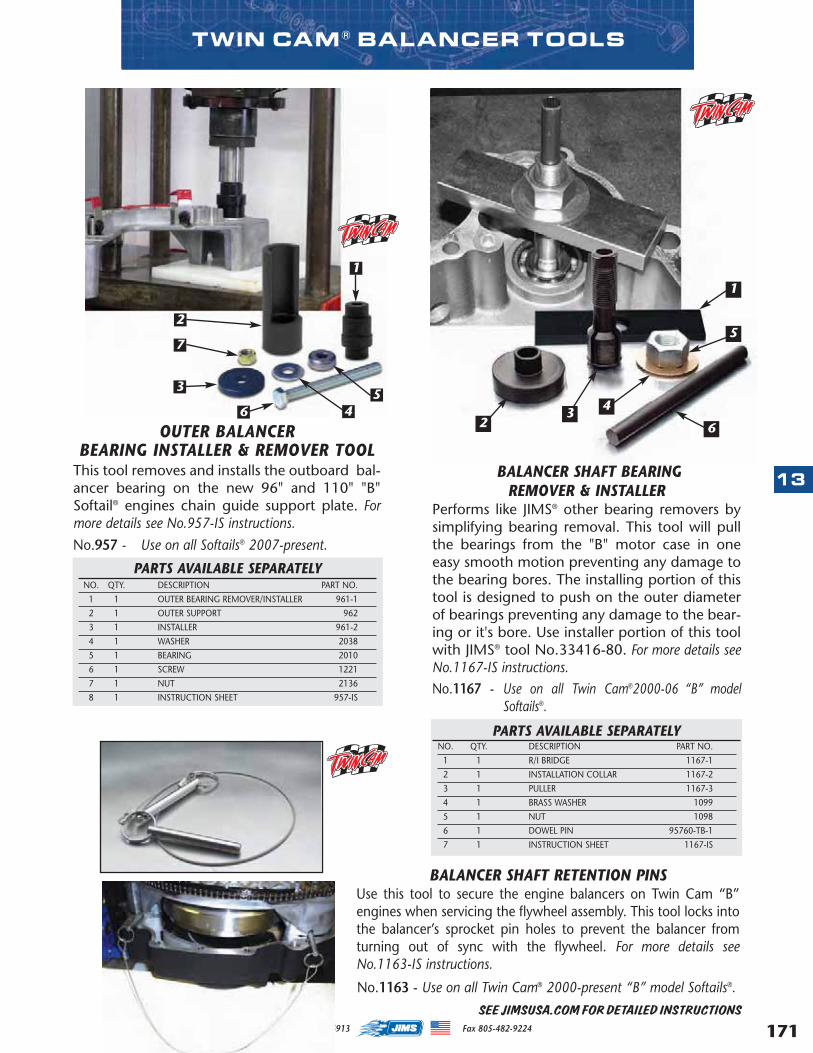
171
13
Phone 805-482-6913 Fax 805-482-9224
TWIN CAM ® BALANCER TOOLS
BALANCER SHAFT BEARINGREMOVER & INSTALLER
Performs like JIMS® other bearing removers bysimplifying bearing removal. This tool will pullthe bearings from the "B" motor case in oneeasy smooth motion preventing any damage tothe bearing bores. The installing portion of thistool is designed to push on the outer diameterof bearings preventing any damage to the bear-ing or it's bore. Use installer portion of this toolwith JIMS® tool No.33416-80. For more details seeNo.1167-IS instructions.No.1167 - Use on all Twin Cam®2000-06 “B” model
Softails®.
OUTER BALANCERBEARING INSTALLER & REMOVER TOOL
This tool removes and installs the outboard bal-ancer bearing on the new 96" and 110" "B"Softail® engines chain guide support plate. Formore details see No.957-IS instructions.
No.957 - Use on all Softails® 2007-present.
PARTS AVAILABLE SEPARATELYNO. QTY. DESCRIPTION PART NO.
1 1 OUTER BEARING REMOVER/INSTALLER 961-1
2 1 OUTER SUPPORT 962
3 1 INSTALLER 961-2
4 1 WASHER 2038
5 1 BEARING 2010
6 1 SCREW 1221
7 1 NUT 2136
8 1 INSTRUCTION SHEET 957-IS
2
3
6
1
5
63
2
1
45
4
7
BALANCER SHAFT RETENTION PINSUse this tool to secure the engine balancers on Twin Cam “B”engines when servicing the flywheel assembly. This tool locks intothe balancer’s sprocket pin holes to prevent the balancer fromturning out of sync with the flywheel. For more details seeNo.1163-IS instructions.
No.1163 - Use on all Twin Cam® 2000-present “B” model Softails®.
PARTS AVAILABLE SEPARATELYNO. QTY. DESCRIPTION PART NO.
1 1 R/I BRIDGE 1167-1
2 1 INSTALLATION COLLAR 1167-2
3 1 PULLER 1167-3
4 1 BRASS WASHER 1099
5 1 NUT 1098
6 1 DOWEL PIN 95760-TB-1
7 1 INSTRUCTION SHEET 1167-IS
SEE JIMSUSA.COM FOR DETAILED INSTRUCTIONS
MASTER 2013 CATALOG_JMS 2.qxp:Layout 1 8/2/12 8:30 PM Page 171
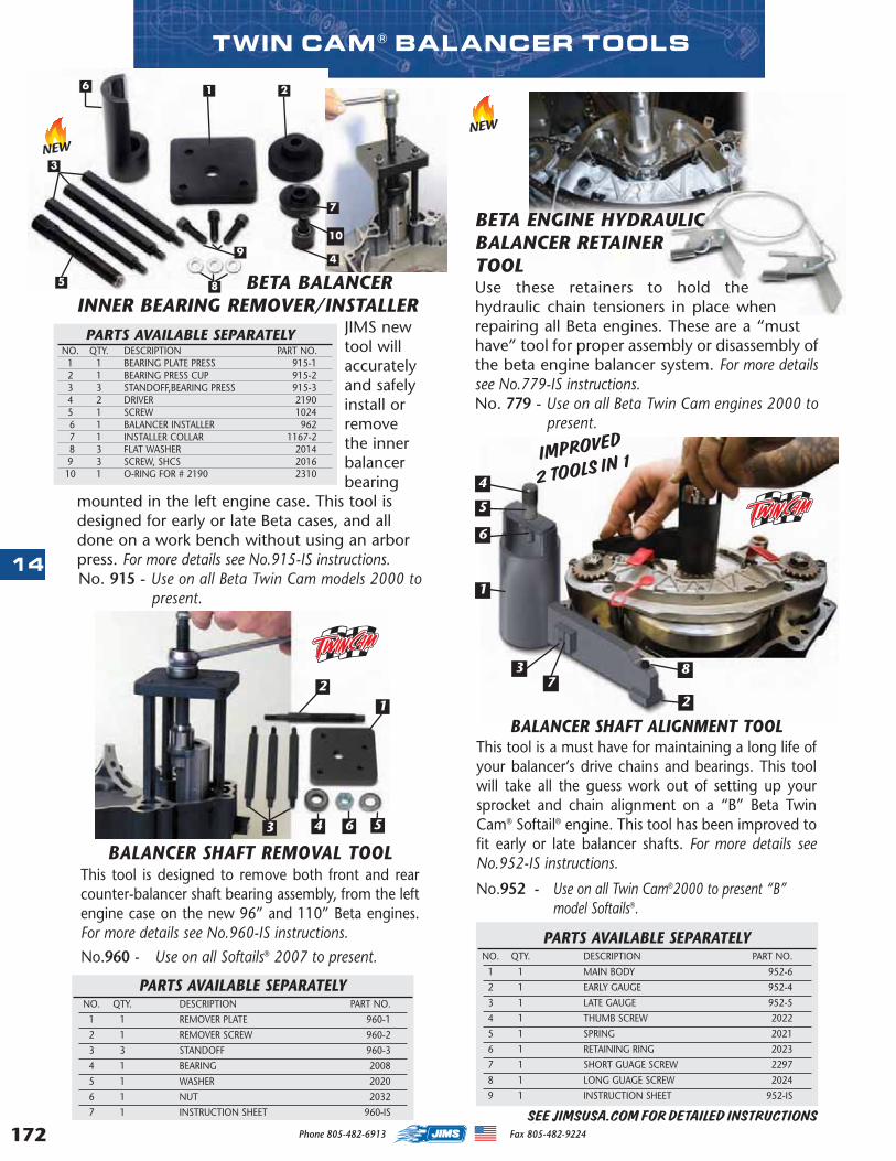
172
14
Phone 805-482-6913 Fax 805-482-9224
BALANCER SHAFT REMOVAL TOOLThis tool is designed to remove both front and rearcounter-balancer shaft bearing assembly, from the leftengine case on the new 96” and 110” Beta engines.For more details see No.960-IS instructions.
No.960 - Use on all Softails® 2007 to present.
12
43 6 5
PARTS AVAILABLE SEPARATELYNO. QTY. DESCRIPTION PART NO.
1 1 REMOVER PLATE 960-1
2 1 REMOVER SCREW 960-2
3 3 STANDOFF 960-3
4 1 BEARING 2008
5 1 WASHER 2020
6 1 NUT 2032
7 1 INSTRUCTION SHEET 960-IS
PARTS AVAILABLE SEPARATELYNO. QTY. DESCRIPTION PART NO.
1 1 MAIN BODY 952-6
2 1 EARLY GAUGE 952-4
3 1 LATE GAUGE 952-5
4 1 THUMB SCREW 2022
5 1 SPRING 2021
6 1 RETAINING RING 2023
7 1 SHORT GUAGE SCREW 2297
8 1 LONG GUAGE SCREW 2024
9 1 INSTRUCTION SHEET 952-IS
4
5
6
1
37
8
2
IMPROVED
2 TOOLS IN 1
SEE JIMSUSA.COM FOR DETAILED INSTRUCTIONS
BALANCER SHAFT ALIGNMENT TOOLThis tool is a must have for maintaining a long life ofyour balancer’s drive chains and bearings. This toolwill take all the guess work out of setting up yoursprocket and chain alignment on a “B” Beta TwinCam® Softail® engine. This tool has been improved tofit early or late balancer shafts. For more details seeNo.952-IS instructions.
No.952 - Use on all Twin Cam®2000 to present “B” model Softails®.
NEW
BETA ENGINE HYDRAULICBALANCER RETAINERTOOLUse these retainers to hold thehydraulic chain tensioners in place whenrepairing all Beta engines. These are a “musthave” tool for proper assembly or disassembly ofthe beta engine balancer system. For more detailssee No.779-IS instructions.No. 779 - Use on all Beta Twin Cam engines 2000 to
present.
NEW
BETA BALANCERINNER BEARING REMOVER/INSTALLER
JIMS newtool willaccuratelyand safelyinstall orremovethe innerbalancerbearing
mounted in the left engine case. This tool isdesigned for early or late Beta cases, and alldone on a work bench without using an arborpress. For more details see No.915-IS instructions.No. 915 - Use on all Beta Twin Cam models 2000 to
present.
PARTS AVAILABLE SEPARATELYNO. QTY. DESCRIPTION PART NO.
1 1 BEARING PLATE PRESS 915-12 1 BEARING PRESS CUP 915-2 3 3 STANDOFF,BEARING PRESS 915-34 2 DRIVER 21905 1 SCREW 1024 6 1 BALANCER INSTALLER 962 7 1 INSTALLER COLLAR 1167-2 8 3 FLAT WASHER 2014 9 3 SCREW, SHCS 201610 1 O-RING FOR # 2190 2310
7
4
6
9
21
3
10
5 8
TWIN CAM ® BALANCER TOOLS
MASTER 2013 CATALOG_JMS 2.qxp:Layout 1 8/2/12 8:30 PM Page 172
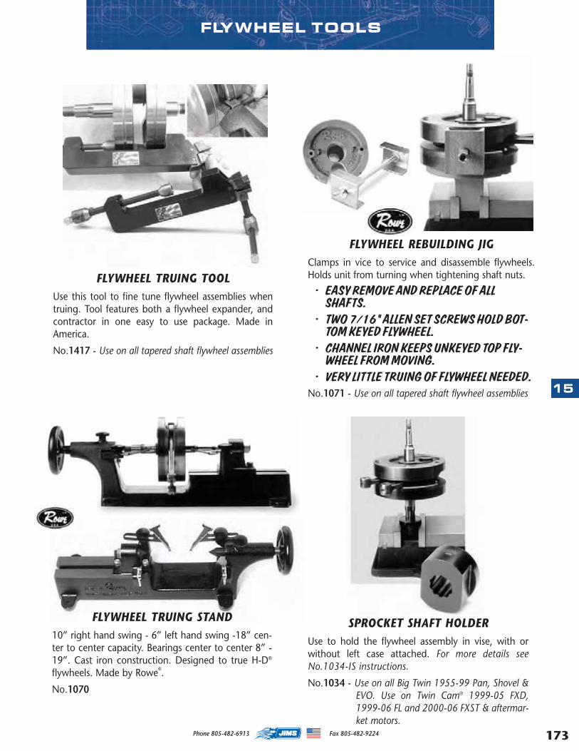
173
15
Phone 805-482-6913 Fax 805-482-9224
FLYWHEEL REBUILDING JIGClamps in vice to service and disassemble flywheels.Holds unit from turning when tightening shaft nuts.
• EASY REMOVE AND REPLACE OF ALLSHAFTS.
• TWO 7/16” ALLEN SET SCREWS HOLD BOT-TOM KEYED FLYWHEEL.
• CHANNEL IRON KEEPS UNKEYED TOP FLY-WHEEL FROM MOVING.
• VERY LITTLE TRUING OF FLYWHEEL NEEDED.No.1071 - Use on all tapered shaft flywheel assemblies
SPROCKET SHAFT HOLDERUse to hold the flywheel assembly in vise, with orwithout left case attached. For more details seeNo.1034-IS instructions.
No.1034 - Use on all Big Twin 1955-99 Pan, Shovel &EVO. Use on Twin Cam® 1999-05 FXD,1999-06 FL and 2000-06 FXST & aftermar-ket motors.
FLYWHEEL TRUING TOOLUse this tool to fine tune flywheel assemblies whentruing. Tool features both a flywheel expander, andcontractor in one easy to use package. Made inAmerica.
No.1417 - Use on all tapered shaft flywheel assemblies
FLYWHEEL TRUING STAND10” right hand swing - 6” left hand swing -18” cen-ter to center capacity. Bearings center to center 8” -19”. Cast iron construction. Designed to true H-D®
flywheels. Made by Rowe®.
No.1070
FLYWHEEL TOOLS
MASTER 2013 CATALOG_JMS 2.qxp:Layout 1 8/2/12 8:30 PM Page 173
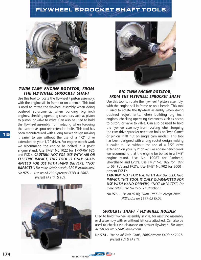
174
15
Phone 805-482-6913Fax 805-482-9224
FLYWHEEL SPROCKET SHAFT TOOLS
TWIN CAM® ENGINE ROTATOR, FROMTHE FLYWHEEL SPROCKET SHAFT
Use this tool to rotate the flywheel / piston assembly,with the engine still in frame or on a bench. This toolis used to rotate the flywheel assembly when doingpushrod adjustments, when building big inchengines, checking operating clearances such as pistonto piston, or valve to valve. Can also be used to holdthe flywheel assembly from rotating when torquingthe cam drive sprockets retention bolts. This tool hasbeen manufactured with a long socket design makingit easier to use without the use of a 1/2” driveextension on your 1/2” driver. For engine bench workwe recommend the engine be bolted in a JIMS®
engine stand. Use JIMS® No.1022 for 1999-06’ FL'Sand FXD’s. CAUTION: NOT FOR USE WITH AIR ORELECTRIC IMPACT, THIS TOOL IS ONLY GUAR-ANTEED FOR USE WITH HAND DRIVERS, “NOTIMPACTS”. For more details see No.975-IS instructions.No.975 - Use on all 2006-present FXD's & 2007-
present FXST's, & FL's.
BIG TWIN ENGINE ROTATOR,FROM THE FLYWHEEL SPROCKET SHAFT
Use this tool to rotate the flywheel / piston assembly,with the engine still in frame or on a bench. This toolis used to rotate the flywheel assembly when doingpushrod adjustments, when building big inchengines, checking operating clearances such as pistonto piston, or valve to valve. Can also be used to holdthe flywheel assembly from rotating when torquingthe cam drive sprocket retention bolts on Twin Cams®
or pinion shaft nut on single cam models. This toolhas been designed with a long socket design makingit easier to use without the use of a 1/2” driveextension on your 1/2” driver. For engine bench workwe recommend that the engine be bolted in a JIMS®
engine stand. Use No. 1006T for Panhead,Shovelhead and EVO's. Use JIMS® No.1022 for 1999to 06’ FL's and FXD's. Use JIMS® No.902 for 2000 -present FXST's. CAUTION: NOT FOR USE WITH AIR OR ELECTRICIMPACT, THIS TOOL IS ONLY GUARANTEED FORUSE WITH HAND DRIVERS, “NOT IMPACTS”. Formore details see No.976-IS instructions.
No.976 - Use on all Big Twins 1955-06 except 2006 FXD's.Use on 1999-05 FXD's.
SPROCKET SHAFT / FLYWHEEL HOLDERUsed to hold flywheel assembly in vise, for assisting assemblyor disassembly with or without left case attached. Can also beused to check case clearance on stroker flywheels. For moredetails see No.974-IS instructions.
No.974 - Use on all Twin Cam®, 2006-present FXD’s or 2007-present FL’s & FXST’s.
MASTER 2013 CATALOG_JMS 2.qxp:Layout 1 8/2/12 8:30 PM Page 174
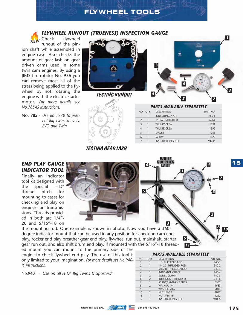
175
15
Phone 805-482-6913 Fax 805-482-9224
FLYWHEEL RUNOUT (TRUENESS) INSPECTION GAUGECheck flywheelrunout of the pin-
ion shaft while assembled inengine case. Also checks theamount of gear lash on geardriven cams used in sometwin cam engines. By using aJIMS tire rotator No. 936 youcan remove most all of thestress being applied to the fly-wheel by not rotating theengine with the electric startermotor. For more details seeNo.785-IS instructions.
No. 785 - Use on 1970 to pres-ent Big Twin, Shovels,EVO and Twin
END PLAY GAUGEINDICATOR TOOLFinally an indicatortool kit designed withthe special H-D®
thread pitch formounting to cases forchecking end play onengines or transmis-sions. Threads provid-ed in both are 1/4”-20 and 5/16”-18 onthe mounting rod. One example is shown in photo. Now you have a 360-degree indicator mount that can be used in any position for checking cam endplay, rocker end play breather gear end play, flywheel run out, mainshaft, startergear run out, and also shift drum end play. If mounted with the 5/16”-18 thread-ed mount you can mount to the primary side of theengine to check flywheel end play. The use of this tool isonly limited to your imagination. For more details see No.940-IS instructions.
No.940 - Use on all H-D® Big Twins & Sporters®.
FLYWHEEL TOOLS
PARTS AVAILABLE SEPARATELYNO. QTY DESCRIPTION PART NO.
1 1 I. D. THREADED ROD 940-12 1 1/4-20 THREADED ROD 940-2 3 1 5/16-18 THREADED ROD 940-3 4 1 INDICATOR GUAGE 940-45 2 SWIVEL CLAMP 940-56 2 ROD, NON - THREADED 940-6 7 1 SCREW,1/4-20X5/8 SHCS 8362 8 2 WASHER, 1/4 1683 9 1 WASHER, 5/16 2014 10 1 NUT 1/4-20 201711 1 NUT 5/16-18 122212 1 INSTRUCTION SHEET 940-IS
1
2
8
6
7
3
9
11
8 10
5
4
PARTS AVAILABLE SEPARATELYNO. QTY. DESCRIPTION PART NO.
1 1 INDICATING PLATE 785-1
2 1 1" DIAL INDICATOR 940-4
3 1 THUMBSCREW 1391
4 1 THUMBSCREW 1392
5 1 SPACER 1085
6 1 SCREW 1122
7 1 INSTRUCTION SHEET 947-IS
1
2
3
5
3
6
4TESTING RUNOUT
TESTING GEAR LASH
NEW
MASTER 2013 CATALOG_JMS 2.qxp:Layout 1 8/2/12 8:30 PM Page 175

176
15
Phone 805-482-6913 Fax 805-482-9224
FLYWHEEL SOCKETS Look no further for the best flywheel rebuilding sockets available. With a low profile, all sockets are just long enoughto give 100% nut to socket contact and 100% drive end contact. Machined flat at the nut receiving end to elimi-nate rounding off the nut and greatly reducing the risk of bodily injury. Machined from solid steel 4130 chromi-um-molybdenum and heat treated to give a lifetime of service. For more details see No.2358-IS instructions.
USE ON ALL BIG TWIN 1954-EARLY 19811-5/16” x 1/2” driveNo.1029-TU - Use to install or remove crank pin nut No.23966-54A.
USE ON ALL BIG TWIN LATE 1983-99 - SINGLE CAM ONLY1-1/2” x 1/2” driveNo.1030-TU - Use to install or remove crank pin nut No.23969-83.
USE ON ALL BIG TWIN LATE 1981-891-1/4” x 1/2” driveNo.1031-TU - Use to install or remove pinion shaft nut No.24016-80.
USE ON ALL BIG TWIN 1972-99 - SINGLE CAM ONLY1-5/8” x 3/4” driveNo.1032-TU - Use to install or remove sprocket shaft nut No.24017-80.
USE ON ALL SPORTSTER® 1981-99 & BUELL® 1987-991-3/8” x 1/2” driveNo.1033-TU - Use to install or remove crank pin nut No.23901-81.
Endorsed By
FLYWHEEL TOOLS
MIGHTY BITE FLYWHEEL LOCKThis tool holds the Twin Cam flywheels in place whenperforming service work to the connecting rods or pis-tons with the cylinders off the engine. Just take out theflywheel position sensor and install the “Mighty Bite”into the case. For more details see instructions No. 753-IS.No. 753 - Use on all Twin Cam motors.
NEW
MASTER 2013 CATALOG_JMS 2.qxp:Layout 1 8/2/12 8:30 PM Page 176
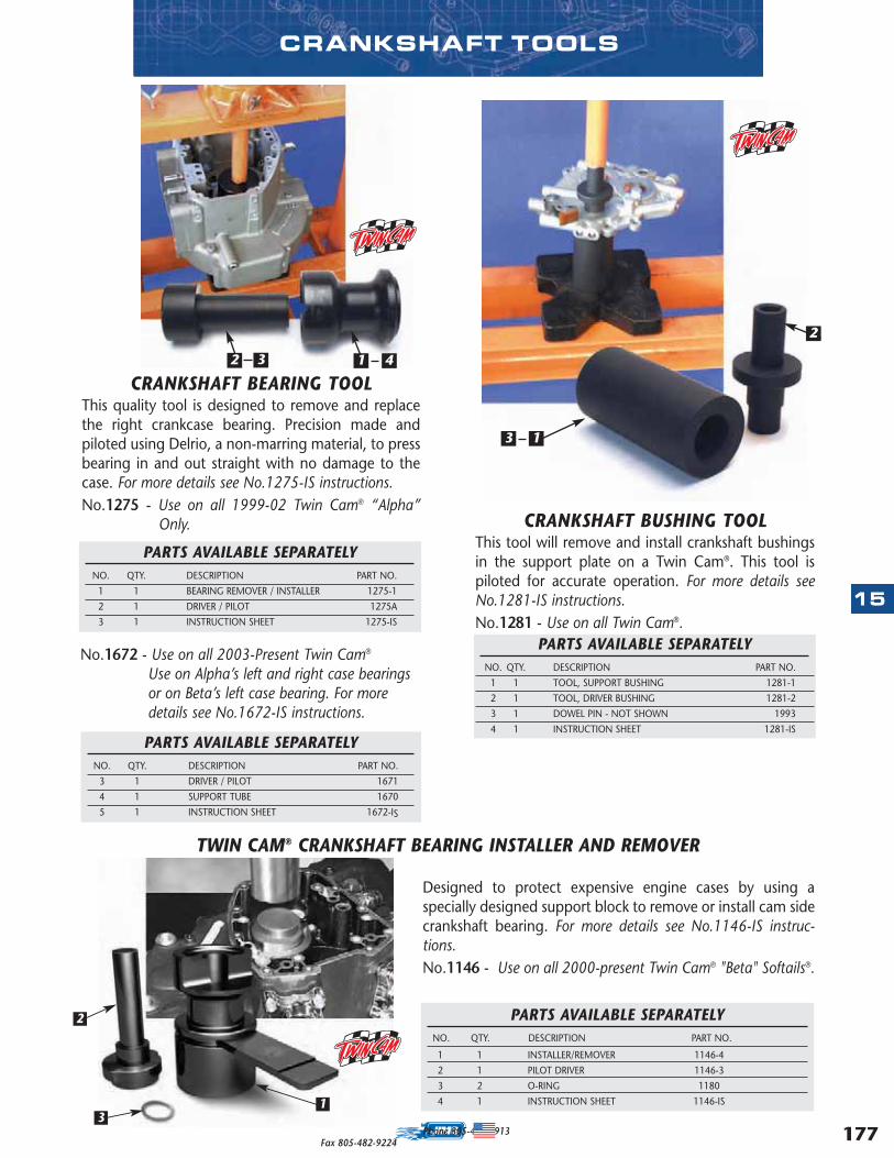
177
15
Phone 805-482-6913Fax 805-482-9224
Designed to protect expensive engine cases by using aspecially designed support block to remove or install cam sidecrankshaft bearing. For more details see No.1146-IS instruc-tions.No.1146 - Use on all 2000-present Twin Cam® "Beta" Softails®.
CRANKSHAFT TOOLS
CRANKSHAFT BEARING TOOLThis quality tool is designed to remove and replacethe right crankcase bearing. Precision made andpiloted using Delrio, a non-marring material, to pressbearing in and out straight with no damage to thecase. For more details see No.1275-IS instructions.No.1275 - Use on all 1999-02 Twin Cam® “Alpha”
Only. CRANKSHAFT BUSHING TOOL This tool will remove and install crankshaft bushingsin the support plate on a Twin Cam®. This tool ispiloted for accurate operation. For more details seeNo.1281-IS instructions.No.1281 - Use on all Twin Cam®.
PARTS AVAILABLE SEPARATELYNO. QTY. DESCRIPTION PART NO.
1 1 TOOL, SUPPORT BUSHING 1281-1
2 1 TOOL, DRIVER BUSHING 1281-2
3 1 DOWEL PIN - NOT SHOWN 1993
4 1 INSTRUCTION SHEET 1281-IS
PARTS AVAILABLE SEPARATELYNO. QTY. DESCRIPTION PART NO.
3 1 DRIVER / PILOT 1671
4 1 SUPPORT TUBE 1670
5 1 INSTRUCTION SHEET 1672-IS
PARTS AVAILABLE SEPARATELYNO. QTY. DESCRIPTION PART NO.
1 1 INSTALLER/REMOVER 1146-4
2 1 PILOT DRIVER 1146-3
3 2 O-RING 1180
4 1 INSTRUCTION SHEET 1146-IS
No.1672 - Use on all 2003-Present Twin Cam®
Use on Alpha’s left and right case bearingsor on Beta’s left case bearing. For moredetails see No.1672-IS instructions.
PARTS AVAILABLE SEPARATELYNO. QTY. DESCRIPTION PART NO.
1 1 BEARING REMOVER / INSTALLER 1275-1
2 1 DRIVER / PILOT 1275A
3 1 INSTRUCTION SHEET 1275-IS
2
31
3 1 4
3 1
2
2
TWIN CAM® CRANKSHAFT BEARING INSTALLER AND REMOVER
MASTER 2013 CATALOG_JMS 2.qxp:Layout 1 8/2/12 8:30 PM Page 177

178
15
Phone 805-482-6913 Fax 805-482-9224
SPROCKET SHAFT BEARING TOOLS
BIG TWIN SPROCKET SHAFTBEARING INSTALLATION TOOL
Use to install flywheel assembly into left crankcaseTimken® bearing. For more details see No.97225-ISinstructions.
No.97225-55 - Use on all Big Twin 1955-2002.(NOTE: Includes JIMS® 120”, 131” & 135” Twin
Cam® and other aftermarket motors.)
PARTS AVAILABLE SEPARATELYNO. QTY. DESCRIPTION PART NO.
1 1 MAIN BODY 97225-55-1
2 1 NUT/HANDLE ASSEMBLY 1026B
3 1 SLIDER 97225-55-3
4 1 LONG HANDLE 1028
5 1 BEARING 2001
6 2 WASHER 2002
7 1 INSTRUCTION SHEET 97225-IS
SPROCKET SHAFT BEARING INSTALLATION TOOL
Use to install crank shaft assembly into crankcaseTimken® bearings. Use with No.97081-54. Use toolNo.37047-91-5 to install the bearing until tool runsout of threads, then install No.37047-91-6 to pushthe bearing on the rest of the way. For more detailssee No.37047-IS instructions.
No.37047-91-6 - Use on all Sportster® 1977-03. Use on all Buell ® 1987-03.2.500” long.
No.37047-91-5 - Use on all Sportster® 1977-03. Use on all Buell ® 1987-03.2.060” long.
Designed to give the bestcontrol on the torque ofbearing pack for checkingbearing end play. Torquenut with JIMS® toolNo.94660-37A for con-sistent professionalresults.
IMPORTANT NOTE:You must use a 94660-37A socket with the97225-55 and the97081-54 tool - Soldseparately on page 194.
2 3
4
5
1
SEE JIMSUSA.COM FOR DETAILED INSTRUCTIONS
SPORTSTER® SPROCKET SHAFT BEARING INSTALLATION TOOL
Use to install flywheel assembly into left crankcaseTimken
®bearing. Use with No. 37047-91-5 sleeve
and No. 37047-91-6 for 1977-2003. For more detailssee No.97081-IS instructions.
No.97081-54 - Use on all Sportsters® and K 1952-76.
PARTS AVAILABLE SEPARATELYNO. QTY. DESCRIPTION PART NO.
1 1 MAIN BODY 97081-54-1
2 1 NUT AND ASSEMBLY 1026B
3 1 SLIDER 97081-54-3
4 1 LONG HANDLE 1028
5 1 BEARING 2001
6 2 WASHER 2002
6 1 INSTRUCTION SHEET 97081-IS
2 34
5
1
CRANKSHAFT GUIDEThis tool will spread crankcase pinion bear-ing rollers while reassembling right side engine caseon to flywheel assembly. For more details seeNo.1288-IS instructions.No.1288 - Use on all Twin Cam®, “Alpha” and “Beta”
1999-present, and XB9R/XB9S 2003-pres-ent.
MASTER 2013 CATALOG_JMS 2.qxp:Layout 1 8/2/12 8:30 PM Page 178
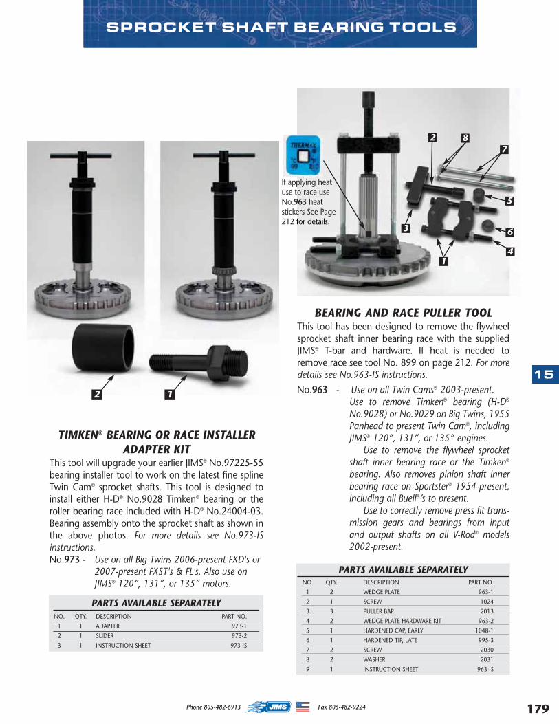
179
15
Phone 805-482-6913 Fax 805-482-9224
SPROCKET SHAFT BEARING TOOLS
BEARING AND RACE PULLER TOOLThis tool has been designed to remove the flywheelsprocket shaft inner bearing race with the suppliedJIMS® T-bar and hardware. If heat is needed toremove race see tool No. 899 on page 212. For moredetails see No.963-IS instructions.
No.963 - Use on all Twin Cams® 2003-present.Use to remove Timken® bearing (H-D®
No.9028) or No.9029 on Big Twins, 1955Panhead to present Twin Cam®, includingJIMS® 120”, 131”, or 135” engines.
Use to remove the flywheel sprocketshaft inner bearing race or the Timken®
bearing. Also removes pinion shaft innerbearing race on Sportster® 1954-present,including all Buell®’s to present.
Use to correctly remove press fit trans-mission gears and bearings from inputand output shafts on all V-Rod® models2002-present.
5
6
4
3
27
8
1
PARTS AVAILABLE SEPARATELYNO. QTY. DESCRIPTION PART NO.
1 2 WEDGE PLATE 963-1
2 1 SCREW 1024
3 3 PULLER BAR 2013
4 2 WEDGE PLATE HARDWARE KIT 963-2
5 1 HARDENED CAP, EARLY 1048-1
6 1 HARDENED TIP, LATE 995-3
7 2 SCREW 2030
8 2 WASHER 2031
9 1 INSTRUCTION SHEET 963-IS
TIMKEN® BEARING OR RACE INSTALLERADAPTER KIT
This tool will upgrade your earlier JIMS® No.97225-55bearing installer tool to work on the latest fine splineTwin Cam® sprocket shafts. This tool is designed toinstall either H-D® No.9028 Timken® bearing or theroller bearing race included with H-D® No.24004-03.Bearing assembly onto the sprocket shaft as shown inthe above photos. For more details see No.973-ISinstructions.No.973 - Use on all Big Twins 2006-present FXD's or
2007-present FXST's & FL's. Also use on JIMS® 120”, 131”, or 135” motors.
PARTS AVAILABLE SEPARATELYNO. QTY. DESCRIPTION PART NO.
1 1 ADAPTER 973-1
2 1 SLIDER 973-2
3 1 INSTRUCTION SHEET 973-IS
2 1
If applying heatuse to race useNo.963 heatstickers See Page212 for details.
MASTER 2013 CATALOG_JMS 2.qxp:Layout 1 8/2/12 8:30 PM Page 179
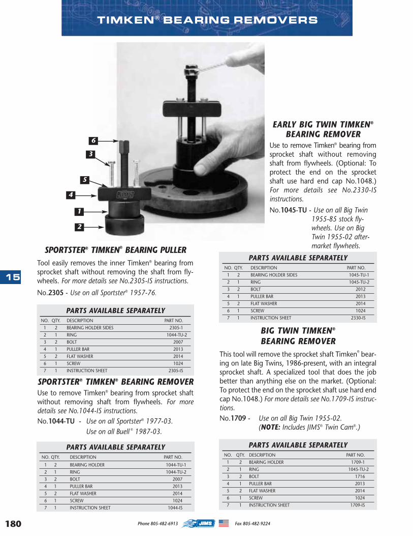
180
15
Phone 805-482-6913 Fax 805-482-9224
EARLY BIG TWIN TIMKEN®
BEARING REMOVERUse to remove Timken® bearing fromsprocket shaft without removingshaft from flywheels. (Optional: Toprotect the end on the sprocketshaft use hard end cap No.1048.)For more details see No.2330-ISinstructions.
No.1045-TU - Use on all Big Twin1955-85 stock fly-wheels. Use on BigTwin 1955-02 after-market flywheels.
PARTS AVAILABLE SEPARATELYNO. QTY. DESCRIPTION PART NO.
1 2 BEARING HOLDER SIDES 1045-TU-1
2 1 RING 1045-TU-2
3 2 BOLT 2012
4 1 PULLER BAR 2013
5 2 FLAT WASHER 2014
6 1 SCREW 1024
7 1 INSTRUCTION SHEET 2330-IS
PARTS AVAILABLE SEPARATELYNO. QTY. DESCRIPTION PART NO.
1 2 BEARING HOLDER 1709-1
2 1 RING 1045-TU-2
3 2 BOLT 1716
4 1 PULLER BAR 2013
5 2 FLAT WASHER 2014
6 1 SCREW 1024
7 1 INSTRUCTION SHEET 1709-IS
SPORTSTER® TIMKEN® BEARING REMOVERUse to remove Timken® bearing from sprocket shaftwithout removing shaft from flywheels. For moredetails see No.1044-IS instructions.No.1044-TU - Use on all Sportster® 1977-03.
Use on all Buell ® 1987-03.
PARTS AVAILABLE SEPARATELYNO. QTY. DESCRIPTION PART NO.
1 2 BEARING HOLDER 1044-TU-1
2 1 RING 1044-TU-2
3 2 BOLT 2007
4 1 PULLER BAR 2013
5 2 FLAT WASHER 2014
6 1 SCREW 1024
7 1 INSTRUCTION SHEET 1044-IS
PARTS AVAILABLE SEPARATELYNO. QTY. DESCRIPTION PART NO.
1 2 BEARING HOLDER SIDES 2305-1
2 1 RING 1044-TU-2
3 2 BOLT 2007
4 1 PULLER BAR 2013
5 2 FLAT WASHER 2014
6 1 SCREW 1024
7 1 INSTRUCTION SHEET 2305-IS
SPORTSTER® TIMKEN® BEARING PULLERTool easily removes the inner Timken® bearing fromsprocket shaft without removing the shaft from fly-wheels. For more details see No.2305-IS instructions.
No.2305 - Use on all Sportster® 1957-76.
TIMKEN ® BEARING REMOVERS
BIG TWIN TIMKEN®
BEARING REMOVERThis tool will remove the sprocket shaft Timken® bear-ing on late Big Twins, 1986-present, with an integralsprocket shaft. A specialized tool that does the jobbetter than anything else on the market. (Optional:To protect the end on the sprocket shaft use hard endcap No.1048.) For more details see No.1709-IS instruc-tions.No.1709 - Use on all Big Twin 1955-02.
(NOTE: Includes JIMS® Twin Cam®.)
1
2
3
4
5
6
MASTER 2013 CATALOG_JMS 2.qxp:Layout 1 8/2/12 8:30 PM Page 180
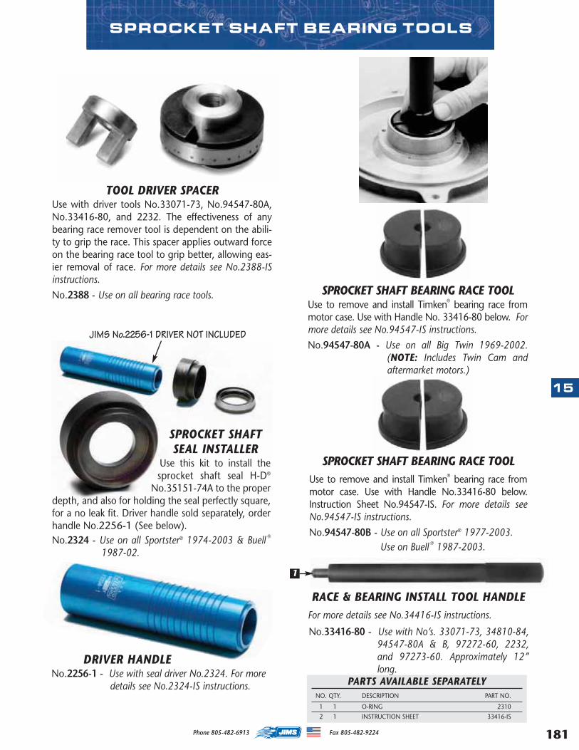
181
15
Phone 805-482-6913 Fax 805-482-9224
SPROCKET SHAFT BEARING RACE TOOLUse to remove and install Timken® bearing race frommotor case. Use with Handle No. 33416-80 below. Formore details see No.94547-IS instructions.
No.94547-80A - Use on all Big Twin 1969-2002.(NOTE: Includes Twin Cam andaftermarket motors.)
TOOL DRIVER SPACERUse with driver tools No.33071-73, No.94547-80A,No.33416-80, and 2232. The effectiveness of anybearing race remover tool is dependent on the abili-ty to grip the race. This spacer applies outward forceon the bearing race tool to grip better, allowing eas-ier removal of race. For more details see No.2388-ISinstructions.
No.2388 - Use on all bearing race tools.
SPROCKET SHAFT BEARING RACE TOOLUse to remove and install Timken® bearing race frommotor case. Use with Handle No.33416-80 below.Instruction Sheet No.94547-IS. For more details seeNo.94547-IS instructions.
No.94547-80B - Use on all Sportster® 1977-2003.Use on Buell ® 1987-2003.
RACE & BEARING INSTALL TOOL HANDLEFor more details see No.34416-IS instructions.
No.33416-80 - Use with No’s. 33071-73, 34810-84,94547-80A & B, 97272-60, 2232,and 97273-60. Approximately 12”long.
PARTS AVAILABLE SEPARATELYNO. QTY. DESCRIPTION PART NO.
1 1 O-RING 2310
2 1 INSTRUCTION SHEET 33416-IS
SPROCKET SHAFT BEARING TOOLS
JIMS No.2256-1 DRIVER NOT INCLUDED
SPROCKET SHAFTSEAL INSTALLER
Use this kit to install thesprocket shaft seal H-D®
No.35151-74A to the properdepth, and also for holding the seal perfectly square,for a no leak fit. Driver handle sold separately, orderhandle No.2256-1 (See below). No.2324 - Use on all Sportster® 1974-2003 & Buell ®
1987-02.
1
DRIVER HANDLENo.2256-1 - Use with seal driver No.2324. For more
details see No.2324-IS instructions.
MASTER 2013 CATALOG_JMS 2.qxp:Layout 1 8/2/12 8:30 PM Page 181
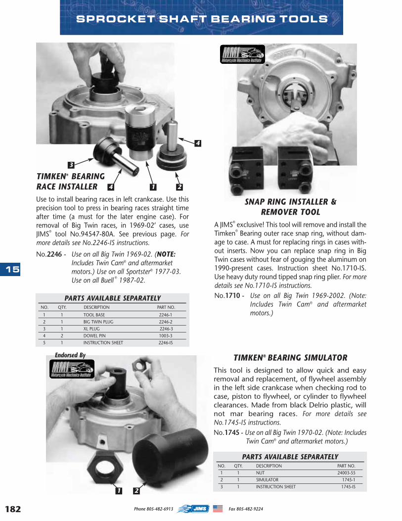
182
15
TIMKEN® BEARING RACE INSTALLERUse to install bearing races in left crankcase. Use thisprecision tool to press in bearing races straight timeafter time (a must for the later engine case). Forremoval of Big Twin races, in 1969-02’ cases, useJIMS® tool No.94547-80A. See previous page. Formore details see No.2246-IS instructions.
No.2246 - Use on all Big Twin 1969-02. (NOTE:Includes Twin Cam® and aftermarketmotors.) Use on all Sportster® 1977-03.Use on all Buell ® 1987-02.
SPROCKET SHAFT BEARING TOOLS
TIMKEN® BEARING SIMULATORThis tool is designed to allow quick and easyremoval and replacement, of flywheel assemblyin the left side crankcase when checking rod tocase, piston to flywheel, or cylinder to flywheelclearances. Made from black Delrio plastic, willnot mar bearing races. For more details seeNo.1745-IS instructions.No.1745 - Use on all Big Twin 1970-02. (Note: Includes
Twin Cam® and aftermarket motors.)
PARTS AVAILABLE SEPARATELYNO. QTY. DESCRIPTION PART NO.
1 1 NUT 24003-55
2 1 SIMULATOR 1745-1
3 1 INSTRUCTION SHEET 1745-IS
Endorsed By
PARTS AVAILABLE SEPARATELYNO. QTY. DESCRIPTION PART NO.
1 1 TOOL BASE 2246-1
2 1 BIG TWIN PLUG 2246-2
3 1 XL PLUG 2246-3
4 2 DOWEL PIN 1003-3
5 1 INSTRUCTION SHEET 2246-IS
3
4
4 21
1 2
SNAP RING INSTALLER & REMOVER TOOL
A JIMS® exclusive! This tool will remove and install theTimken® Bearing outer race snap ring, without dam-age to case. A must for replacing rings in cases with-out inserts. Now you can replace snap ring in BigTwin cases without fear of gouging the aluminum on1990-present cases. Instruction sheet No.1710-IS.Use heavy duty round tipped snap ring plier. For moredetails see No.1710-IS instructions.No.1710 - Use on all Big Twin 1969-2002. (Note:
Includes Twin Cam® and aftermarketmotors.)
Phone 805-482-6913 Fax 805-482-9224
MASTER 2013 CATALOG_JMS 2.qxp:Layout 1 8/2/12 8:30 PM Page 182
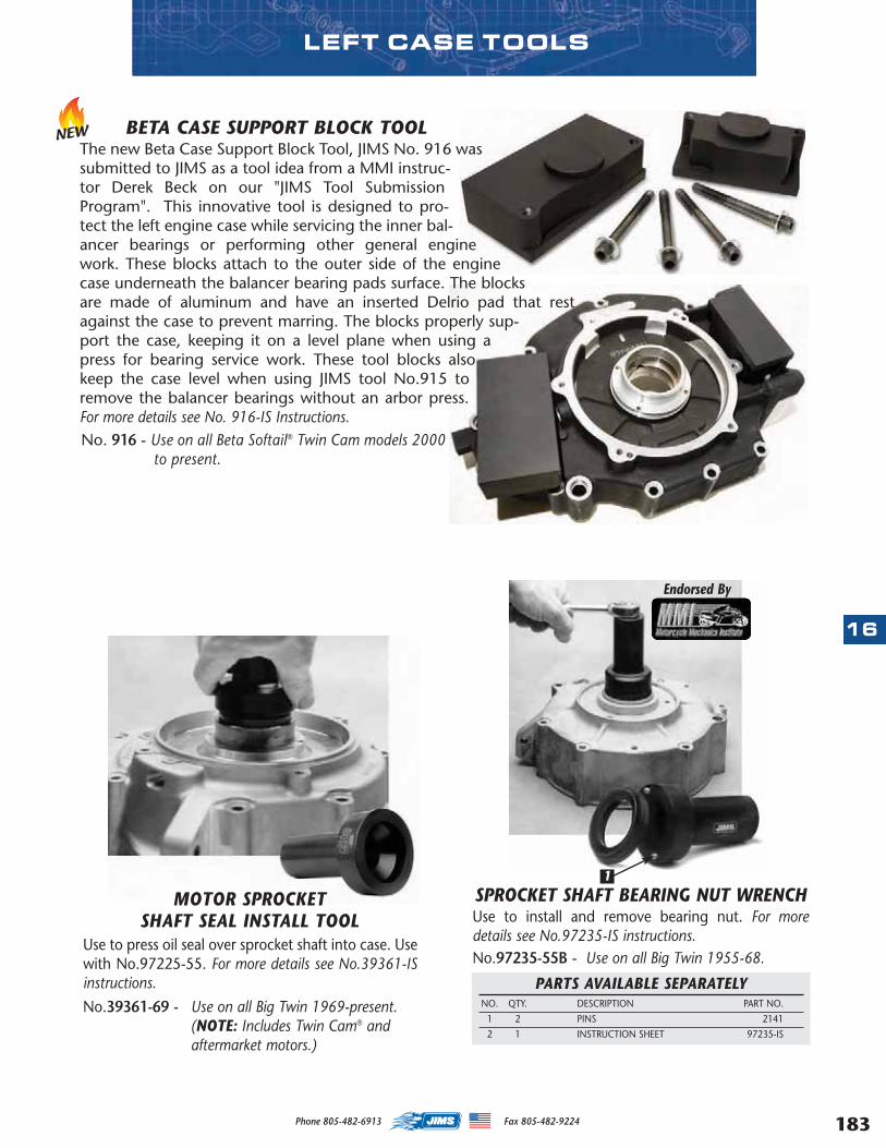
LEFT CASE TOOLS
SPROCKET SHAFT BEARING NUT WRENCHUse to install and remove bearing nut. For moredetails see No.97235-IS instructions.No.97235-55B - Use on all Big Twin 1955-68.
PARTS AVAILABLE SEPARATELYNO. QTY. DESCRIPTION PART NO.
1 2 PINS 2141
2 1 INSTRUCTION SHEET 97235-IS
Endorsed By
MOTOR SPROCKET SHAFT SEAL INSTALL TOOL
Use to press oil seal over sprocket shaft into case. Usewith No.97225-55. For more details see No.39361-ISinstructions.
No.39361-69 - Use on all Big Twin 1969-present. (NOTE: Includes Twin Cam® and aftermarket motors.)
1
BETA CASE SUPPORT BLOCK TOOLThe new Beta Case Support Block Tool, JIMS No. 916 wassubmitted to JIMS as a tool idea from a MMI instruc-tor Derek Beck on our "JIMS Tool SubmissionProgram". This innovative tool is designed to pro-tect the left engine case while servicing the inner bal-ancer bearings or performing other general enginework. These blocks attach to the outer side of the enginecase underneath the balancer bearing pads surface. The blocksare made of aluminum and have an inserted Delrio pad that restagainst the case to prevent marring. The blocks properly sup-port the case, keeping it on a level plane when using apress for bearing service work. These tool blocks alsokeep the case level when using JIMS tool No.915 toremove the balancer bearings without an arbor press.For more details see No. 916-IS Instructions.No. 916 - Use on all Beta Softail® Twin Cam models 2000
to present.
NEW
16
183Phone 805-482-6913 Fax 805-482-9224
MASTER 2013 CATALOG_JMS 2.qxp:Layout 1 8/2/12 8:30 PM Page 183
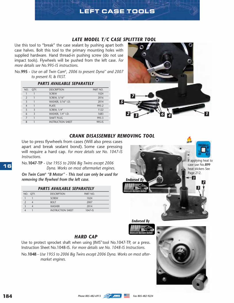
184
16
CRANK DISASSEMBLY REMOVING TOOLUse to press flywheels from cases (Will also press casesapart and break sealant bond). Some case pressingwill require a hard cap. For more details see No. 1047-ISInstructions.
No.1047-TP - Use 1955 to 2006 Big Twins except 2006Dyna. Works on most aftermarket engines.
On Twin Cam® “B Motor” - This tool can only be used forremoving the flywheel from the left case.
PARTS AVAILABLE SEPARATELYNO. QTY. DESCRIPTION PART NO.
1 1 SCREW 1024
2 4 BOLT 2007
3 4 WASHER 2014
4 1 INSTRUCTION SHEET 1047-IS
HARD CAPUse to protect sprocket shaft when using JIMS® tool No.1047-TP, or a press.Instruction Sheet No.1048-IS. For more details see No. 1048-IS Instructions.
No.1048 - Use 1955 to 2006 Big Twins except 2006 Dyna. Works on most after-market engines.
LATE MODEL T/C CASE SPLITTER TOOLUse this tool to “break” the case sealant by pushing apart bothcase halves. Bolt this tool to the primary mounting holes withsupplied hardware. Hand thread-in pushing screw (do not useimpact tools). Flywheels will be pushed from the left case. Formore details see No.995-IS instructions.
No.995 - Use on all Twin Cam®, 2006 to present Dyna™ and 2007to present FL & FXST.
PARTS AVAILABLE SEPARATELYNO. QTY. DESCRIPTION PART NO.
1 1 SCREW 1024
2 1 SCREW, 5/16” 2016
3 1 WASHER, 5/16” I.D. 2014
4 1 PLATE 995-2
5 3 SCREW, 1/4” 1122
6 3 WASHER, 1/4” I.D. 1683
7 1 SHAFT PLUG 995-3
8 1 INSTRUCTION SHEET 995-IS
1
75
2 3 4
12
3
6
Endorsed By
Endorsed By
LEFT CASE TOOLS
If applying heat tocase use No.899heat stickers SeePage 212.
NEW
Phone 805-482-6913 Fax 805-482-9224
MASTER 2013 CATALOG_JMS 2.qxp:Layout 1 8/2/12 8:30 PM Page 184
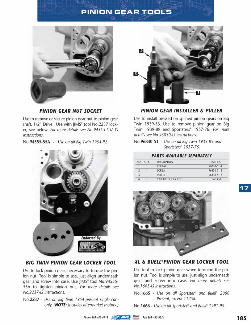
PINION GEAR NUT SOCKETUse to remove or secure pinion gear nut to pinion gearshaft. 1/2” Drive. Use with JIMS® tool No.2237 lock-er, see below. For more details see No.94555-55A-ISinstructions.
No.94555-55A - Use on all Big Twin 1954-92.
PINION GEAR INSTALLER & PULLERUse to install pressed on splined pinion gears on BigTwin 1939-53. Use to remove pinion gear on BigTwin 1939-89 and Sportsters® 1957-76. For moredetails see No.96830-IS instructions.
No.96830-51 - Use on all Big Twin 1939-89 and Sportsters® 1957-76.
PARTS AVAILABLE SEPARATELYNO. QTY. DESCRIPTION PART NO.
1 1 COLLAR 96830-51-1
2 1 SCREW 96830-51-2
3 1 PULLER 96830-51-3
4 1 INSTRUCTION SHEET 96830-IS
BIG TWIN PINION GEAR LOCKER TOOLUse to lock pinion gear, necessary to torque the pin-ion nut. Tool is simple to use, just align underneathgear and screw into case. Use JIMS® tool No.94555-55A to tighten pinion nut. For more details seeNo.2237-IS instructions.
No.2237 - Use on Big Twin 1954-present single camonly. (NOTE: Includes aftermarket motors.)
PINION GEAR TOOLS
Endorsed By
XL & BUELL®PINION GEAR LOCKER TOOLUse tool to lock pinion gear when torquing the pin-ion nut. Tool is simple to use, just align underneathgear and screw into case. For more details seeNo.1665-IS instructions.
No.1665 - Use on all Sportster® and Buell® 2000Present, except 1125R.
No.1666 - Use on all Sportster® and Buell® 1991-99.
1
2
3
17
185Phone 805-482-6913 Fax 805-482-9224
MASTER 2013 CATALOG_JMS 2.qxp:Layout 1 8/2/12 8:30 PM Page 185
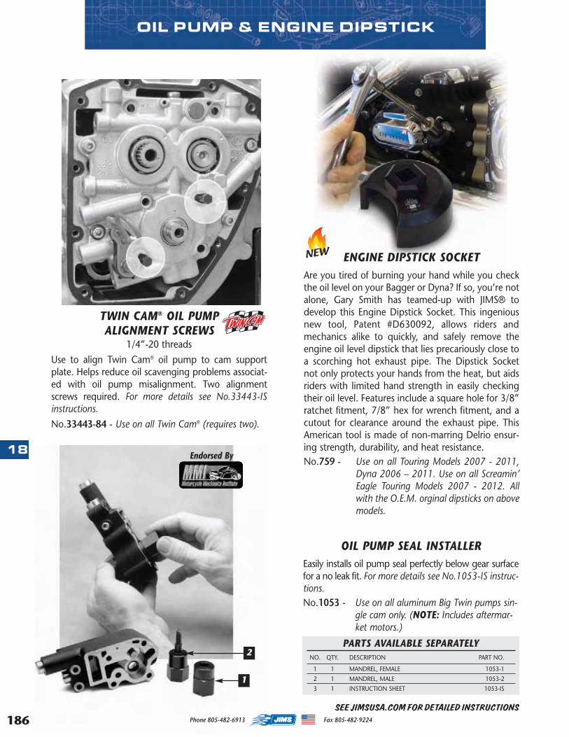
186
18
PARTS AVAILABLE SEPARATELYNO. QTY. DESCRIPTION PART NO.
1 1 MANDREL, FEMALE 1053-1
2 1 MANDREL, MALE 1053-2
3 1 INSTRUCTION SHEET 1053-IS
OIL PUMP SEAL INSTALLEREasily installs oil pump seal perfectly below gear surfacefor a no leak fit. For more details see No.1053-IS instruc-tions.No.1053 - Use on all aluminum Big Twin pumps sin-
gle cam only. (NOTE: Includes aftermar-ket motors.)
Endorsed By
TWIN CAM® OIL PUMP ALIGNMENT SCREWS
1/4”-20 threads
Use to align Twin Cam® oil pump to cam supportplate. Helps reduce oil scavenging problems associat-ed with oil pump misalignment. Two alignmentscrews required. For more details see No.33443-ISinstructions.
No.33443-84 - Use on all Twin Cam® (requires two).
2
1
OIL PUMP & ENGINE DIPSTICK
SEE JIMSUSA.COM FOR DETAILED INSTRUCTIONS
ENGINE DIPSTICK SOCKETAre you tired of burning your hand while you checkthe oil level on your Bagger or Dyna? If so, you’re notalone, Gary Smith has teamed-up with JIMS® todevelop this Engine Dipstick Socket. This ingeniousnew tool, Patent #D630092, allows riders andmechanics alike to quickly, and safely remove theengine oil level dipstick that lies precariously close toa scorching hot exhaust pipe. The Dipstick Socketnot only protects your hands from the heat, but aidsriders with limited hand strength in easily checkingtheir oil level. Features include a square hole for 3/8”ratchet fitment, 7/8” hex for wrench fitment, and acutout for clearance around the exhaust pipe. ThisAmerican tool is made of non-marring Delrio ensur-ing strength, durability, and heat resistance. No.759 - Use on all Touring Models 2007 - 2011,
Dyna 2006 – 2011. Use on all Screamin’Eagle Touring Models 2007 - 2012. Allwith the O.E.M. orginal dipsticks on abovemodels.
NEW
Phone 805-482-6913 Fax 805-482-9224
MASTER 2013 CATALOG_JMS 2.qxp:Layout 1 8/2/12 8:30 PM Page 186
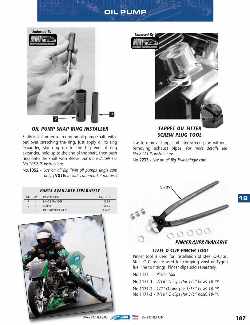
OIL PUMP
OIL PUMP SNAP RING INSTALLEREasily install outer snap ring on oil pump shaft, with-out over stretching the ring. Just apply oil to ringexpander, slip ring up to the big end of ringexpander, hold up to the end of the shaft, then pushring onto the shaft with sleeve. For more details seeNo.1052-IS instructions.No.1052 - Use on all Big Twin oil pumps single cam
only. (NOTE: Includes aftermarket motors.)
PARTS AVAILABLE SEPARATELYNO. QTY. DESCRIPTION PART NO.
1 1 RING EXPANDER 1052-1
2 1 SLEEVE 1052-2
3 1 INSTRUCTION SHEET 1052-IS
TAPPET OIL FILTER SCREW PLUG TOOL
Use to remove tappet oil filter screen plug withoutremoving exhaust pipes. For more details seeNo.2233-IS instructions.No.2233 - Use on all Big Twins single cam.
Endorsed ByEndorsed By
STEEL O-CLIP PINCER TOOLPincer tool is used for installation of steel O-Clips.Steel O-Clips are used for crimping vinyl or Tygonfuel line to fittings. Pincer clips sold separately.
No.1171 - Pincer Tool
No.1171-1 - 7/16” O-clips (for 1/4” hose) 10-PK
No.1171-2 - 1/2” O-clips (for 5/16” hose) 10-PKNo.1171-3 - 9/16” O-clips (for 3/8” hose) 10-PK
No.1171
PINCER CLIPS AVAILABLE
21
18
187Phone 805-482-6913 Fax 805-482-9224
MASTER 2013 CATALOG_JMS 2.qxp:Layout 1 8/2/12 8:30 PM Page 187
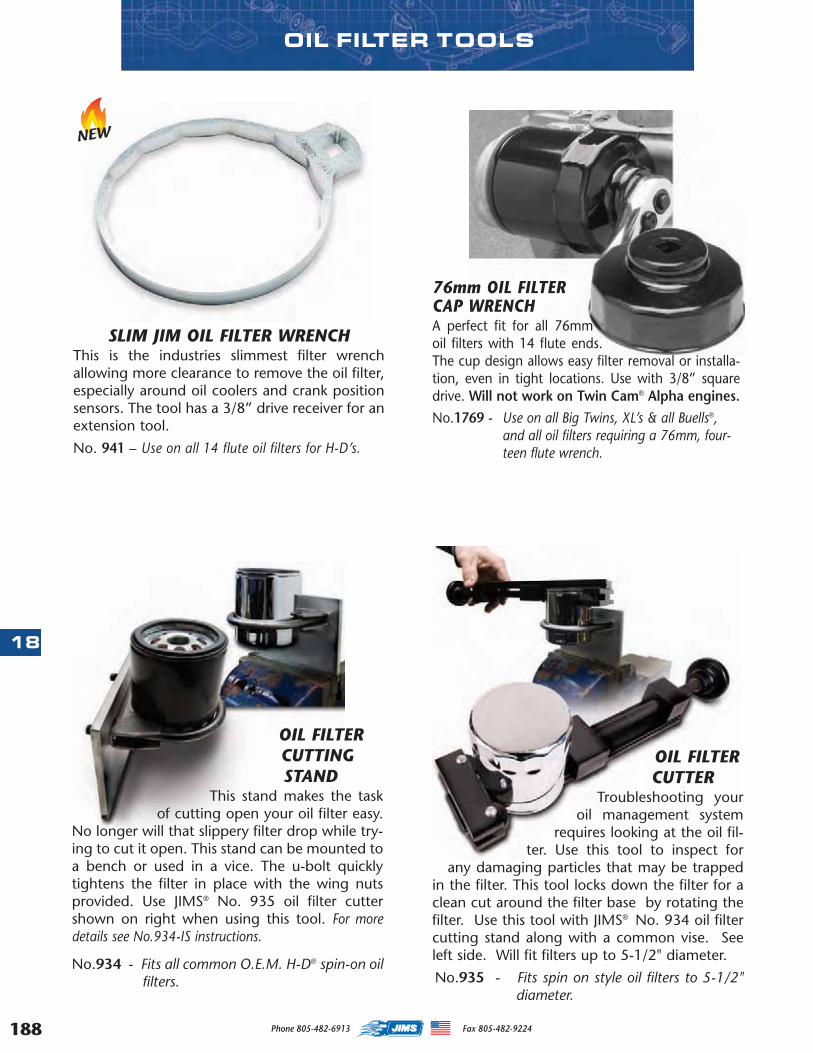
188
18
OIL FILTERCUTTINGSTAND
This stand makes the taskof cutting open your oil filter easy.
No longer will that slippery filter drop while try-ing to cut it open. This stand can be mounted toa bench or used in a vice. The u-bolt quicklytightens the filter in place with the wing nutsprovided. Use JIMS® No. 935 oil filter cuttershown on right when using this tool. For moredetails see No.934-IS instructions.
No.934 - Fits all common O.E.M. H-D® spin-on oilfilters.
OIL FILTERCUTTER
Troubleshooting youroil management system
requires looking at the oil fil-ter. Use this tool to inspect for
any damaging particles that may be trappedin the filter. This tool locks down the filter for aclean cut around the filter base by rotating thefilter. Use this tool with JIMS® No. 934 oil filtercutting stand along with a common vise. Seeleft side. Will fit filters up to 5-1/2" diameter.
No.935 - Fits spin on style oil filters to 5-1/2"diameter.
76mm OIL FILTERCAP WRENCHA perfect fit for all 76mmoil filters with 14 flute ends.The cup design allows easy filter removal or installa-tion, even in tight locations. Use with 3/8” squaredrive. Will not work on Twin Cam® Alpha engines.No.1769 - Use on all Big Twins, XL’s & all Buells®,
and all oil filters requiring a 76mm, four-teen flute wrench.
OIL FILTER TOOLS
SLIM JIM OIL FILTER WRENCHThis is the industries slimmest filter wrenchallowing more clearance to remove the oil filter,especially around oil coolers and crank positionsensors. The tool has a 3/8” drive receiver for anextension tool.
No. 941 – Use on all 14 flute oil filters for H-D’s.
NEW
Phone 805-482-6913 Fax 805-482-9224
MASTER 2013 CATALOG_JMS 2.qxp:Layout 1 8/2/12 8:30 PM Page 188
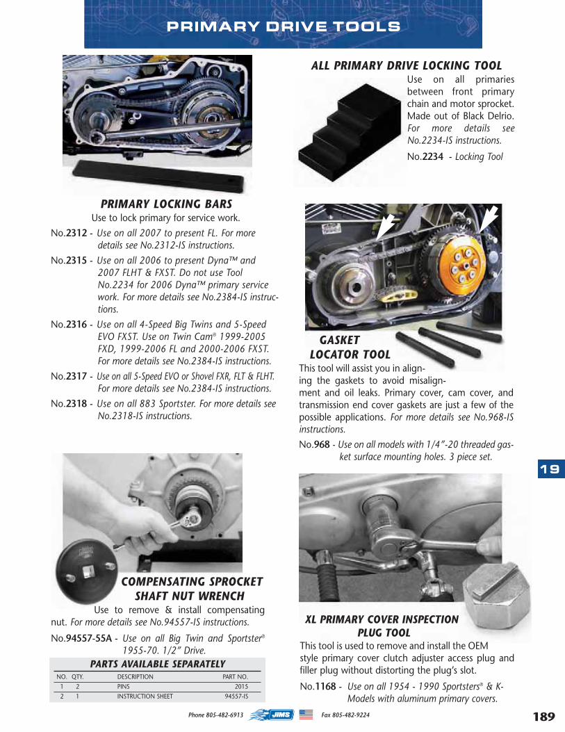
PRIMARY DRIVE TOOLS
XL PRIMARY COVER INSPECTIONPLUG TOOL
This tool is used to remove and install the OEMstyle primary cover clutch adjuster access plug andfiller plug without distorting the plug’s slot.
No.1168 - Use on all 1954 - 1990 Sportsters® & K-Models with aluminum primary covers.
PARTS AVAILABLE SEPARATELYNO. QTY. DESCRIPTION PART NO.
1 2 PINS 2015
2 1 INSTRUCTION SHEET 94557-IS
COMPENSATING SPROCKETSHAFT NUT WRENCH
Use to remove & install compensatingnut. For more details see No.94557-IS instructions.
No.94557-55A - Use on all Big Twin and Sportster®
1955-70. 1/2” Drive.
ALL PRIMARY DRIVE LOCKING TOOLUse on all primariesbetween front primarychain and motor sprocket.Made out of Black Delrio.For more details seeNo.2234-IS instructions.
No.2234 - Locking Tool
GASKETLOCATOR TOOL
This tool will assist you in align-ing the gaskets to avoid misalign-ment and oil leaks. Primary cover, cam cover, andtransmission end cover gaskets are just a few of thepossible applications. For more details see No.968-ISinstructions.
No.968 - Use on all models with 1/4”-20 threaded gas-ket surface mounting holes. 3 piece set.
PRIMARY LOCKING BARSUse to lock primary for service work.
No.2312 - Use on all 2007 to present FL. For moredetails see No.2312-IS instructions.
No.2315 - Use on all 2006 to present Dyna™ and2007 FLHT & FXST. Do not use Tool No.2234 for 2006 Dyna™ primary servicework. For more details see No.2384-IS instruc-tions.
No.2316 - Use on all 4-Speed Big Twins and 5-SpeedEVO FXST. Use on Twin Cam® 1999-2005FXD, 1999-2006 FL and 2000-2006 FXST.For more details see No.2384-IS instructions.
No.2317 - Use on all 5-Speed EVO or Shovel FXR, FLT & FLHT.For more details see No.2384-IS instructions.
No.2318 - Use on all 883 Sportster. For more details seeNo.2318-IS instructions.
19
189Phone 805-482-6913 Fax 805-482-9224
MASTER 2013 CATALOG_JMS 2.qxp:Layout 1 8/2/12 8:30 PM Page 189
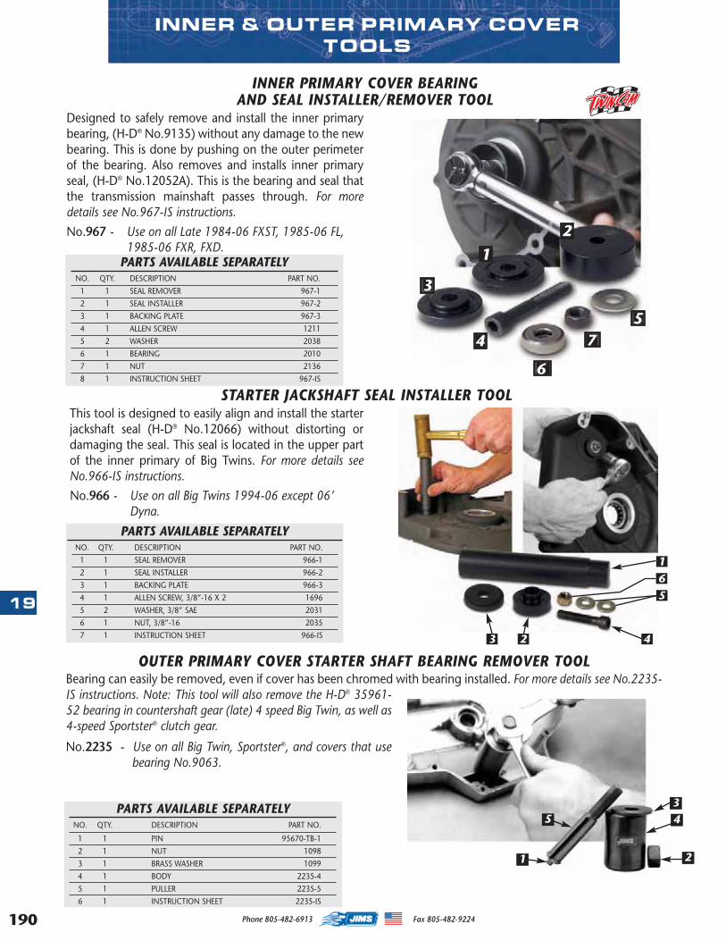
190
19
7
3
1
2
6
54
INNER PRIMARY COVER BEARINGAND SEAL INSTALLER/REMOVER TOOL
Designed to safely remove and install the inner primarybearing, (H-D® No.9135) without any damage to the newbearing. This is done by pushing on the outer perimeterof the bearing. Also removes and installs inner primaryseal, (H-D® No.12052A). This is the bearing and seal thatthe transmission mainshaft passes through. For moredetails see No.967-IS instructions.
No.967 - Use on all Late 1984-06 FXST, 1985-06 FL, 1985-06 FXR, FXD.
PARTS AVAILABLE SEPARATELYNO. QTY. DESCRIPTION PART NO.
1 1 SEAL REMOVER 967-1
2 1 SEAL INSTALLER 967-2
3 1 BACKING PLATE 967-3
4 1 ALLEN SCREW 1211
5 2 WASHER 2038
6 1 BEARING 2010
7 1 NUT 2136
8 1 INSTRUCTION SHEET 967-IS
STARTER JACKSHAFT SEAL INSTALLER TOOLThis tool is designed to easily align and install the starterjackshaft seal (H-D® No.12066) without distorting ordamaging the seal. This seal is located in the upper partof the inner primary of Big Twins. For more details seeNo.966-IS instructions.
No.966 - Use on all Big Twins 1994-06 except 06’ Dyna.
PARTS AVAILABLE SEPARATELYNO. QTY. DESCRIPTION PART NO.
1 1 SEAL REMOVER 966-1
2 1 SEAL INSTALLER 966-2
3 1 BACKING PLATE 966-3
4 1 ALLEN SCREW, 3/8”-16 X 2 1696
5 2 WASHER, 3/8” SAE 2031
6 1 NUT, 3/8”-16 2035
7 1 INSTRUCTION SHEET 966-IS
5
16
43 2
INNER & OUTER PRIMARY COVERTOOLS
PARTS AVAILABLE SEPARATELYNO. QTY. DESCRIPTION PART NO.
1 1 PIN 95670-TB-1
2 1 NUT 1098
3 1 BRASS WASHER 1099
4 1 BODY 2235-4
5 1 PULLER 2235-5
6 1 INSTRUCTION SHEET 2235-IS
OUTER PRIMARY COVER STARTER SHAFT BEARING REMOVER TOOLBearing can easily be removed, even if cover has been chromed with bearing installed. For more details see No.2235-IS instructions. Note: This tool will also remove the H-D® 35961-52 bearing in countershaft gear (late) 4 speed Big Twin, as well as4-speed Sportster® clutch gear.
No.2235 - Use on all Big Twin, Sportster®, and covers that usebearing No.9063.
3
2
45
1
Phone 805-482-6913 Fax 805-482-9224
MASTER 2013 CATALOG_JMS 2.qxp:Layout 1 8/2/12 8:30 PM Page 190
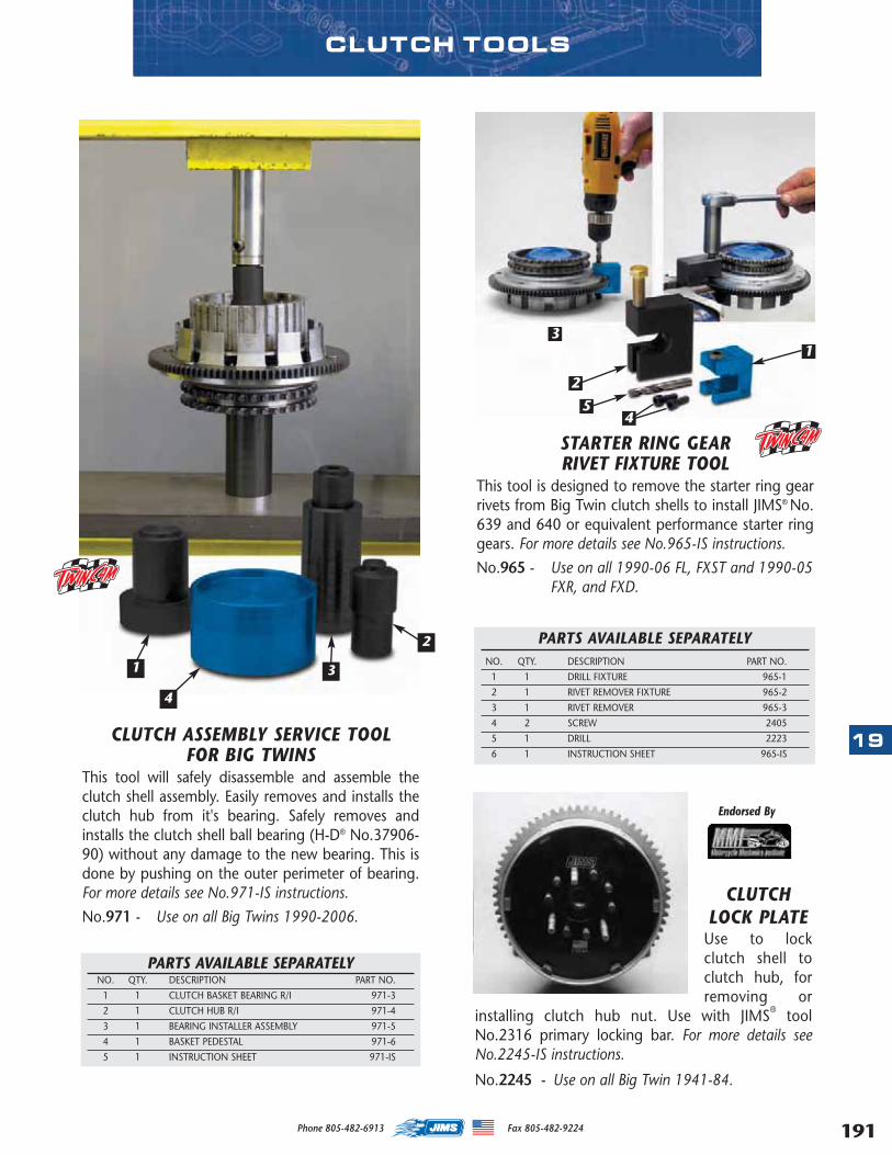
CLUTCH ASSEMBLY SERVICE TOOLFOR BIG TWINS
This tool will safely disassemble and assemble theclutch shell assembly. Easily removes and installs theclutch hub from it's bearing. Safely removes andinstalls the clutch shell ball bearing (H-D® No.37906-90) without any damage to the new bearing. This isdone by pushing on the outer perimeter of bearing.For more details see No.971-IS instructions.
No.971 - Use on all Big Twins 1990-2006.
PARTS AVAILABLE SEPARATELYNO. QTY. DESCRIPTION PART NO.
1 1 CLUTCH BASKET BEARING R/I 971-3
2 1 CLUTCH HUB R/I 971-4
3 1 BEARING INSTALLER ASSEMBLY 971-5
4 1 BASKET PEDESTAL 971-6
5 1 INSTRUCTION SHEET 971-IS
1
4
3
2
STARTER RING GEARRIVET FIXTURE TOOL
This tool is designed to remove the starter ring gearrivets from Big Twin clutch shells to install JIMS® No.639 and 640 or equivalent performance starter ringgears. For more details see No.965-IS instructions.
No.965 - Use on all 1990-06 FL, FXST and 1990-05FXR, and FXD.
PARTS AVAILABLE SEPARATELYNO. QTY. DESCRIPTION PART NO.
1 1 DRILL FIXTURE 965-1
2 1 RIVET REMOVER FIXTURE 965-2
3 1 RIVET REMOVER 965-3
4 2 SCREW 2405
5 1 DRILL 2223
6 1 INSTRUCTION SHEET 965-IS
1
2
3
45
CLUTCH TOOLS
Endorsed By
CLUTCHLOCK PLATE
Use to lockclutch shell toclutch hub, forremoving or
installing clutch hub nut. Use with JIMS® toolNo.2316 primary locking bar. For more details seeNo.2245-IS instructions.
No.2245 - Use on all Big Twin 1941-84.
19
191Phone 805-482-6913 Fax 805-482-9224
MASTER 2013 CATALOG_JMS 2.qxp:Layout 1 8/2/12 8:30 PM Page 191
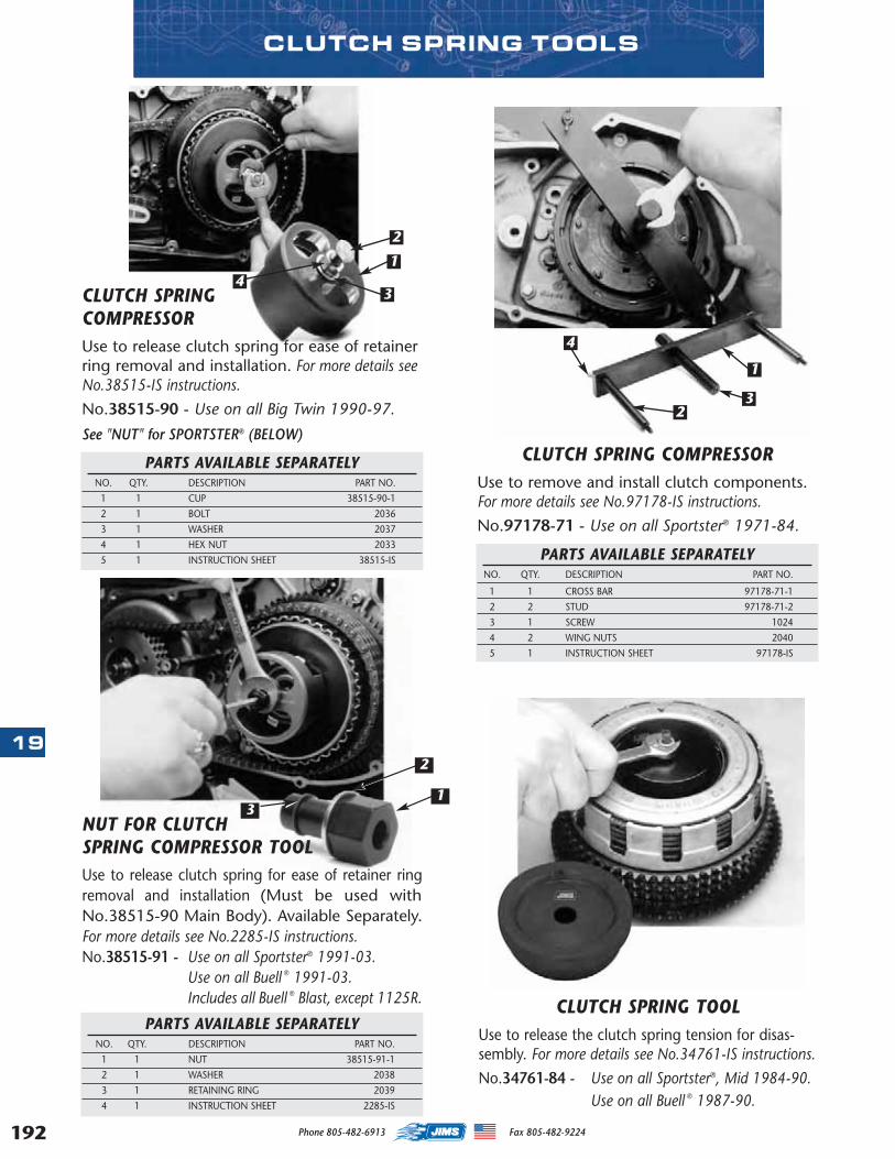
192
19
CLUTCH SPRING COMPRESSORUse to release clutch spring for ease of retainerring removal and installation. For more details seeNo.38515-IS instructions.
No.38515-90 - Use on all Big Twin 1990-97.
See "NUT" for SPORTSTER® (BELOW) CLUTCH SPRING COMPRESSOR
Use to remove and install clutch components.For more details see No.97178-IS instructions.
No.97178-71 - Use on all Sportster® 1971-84.
CLUTCH SPRING TOOLUse to release the clutch spring tension for disas-sembly. For more details see No.34761-IS instructions.
No.34761-84 - Use on all Sportster®, Mid 1984-90.Use on all Buell ® 1987-90.
1
23
4
1
1
2
34
PARTS AVAILABLE SEPARATELYNO. QTY. DESCRIPTION PART NO.
1 1 CUP 38515-90-1
2 1 BOLT 2036
3 1 WASHER 2037
4 1 HEX NUT 2033
5 1 INSTRUCTION SHEET 38515-IS PARTS AVAILABLE SEPARATELYNO. QTY. DESCRIPTION PART NO.
1 1 CROSS BAR 97178-71-1
2 2 STUD 97178-71-2
3 1 SCREW 1024
4 2 WING NUTS 2040
5 1 INSTRUCTION SHEET 97178-IS
PARTS AVAILABLE SEPARATELYNO. QTY. DESCRIPTION PART NO.
1 1 NUT 38515-91-1
2 1 WASHER 2038
3 1 RETAINING RING 2039
4 1 INSTRUCTION SHEET 2285-IS
CLUTCH SPRING TOOLS
2
3NUT FOR CLUTCH SPRING COMPRESSOR TOOLUse to release clutch spring for ease of retainer ringremoval and installation (Must be used withNo.38515-90 Main Body). Available Separately.For more details see No.2285-IS instructions.No.38515-91 - Use on all Sportster® 1991-03.
Use on all Buell ® 1991-03.Includes all Buell ® Blast, except 1125R.
Phone 805-482-6913 Fax 805-482-9224
MASTER 2013 CATALOG_JMS 2.qxp:Layout 1 8/2/12 8:30 PM Page 192
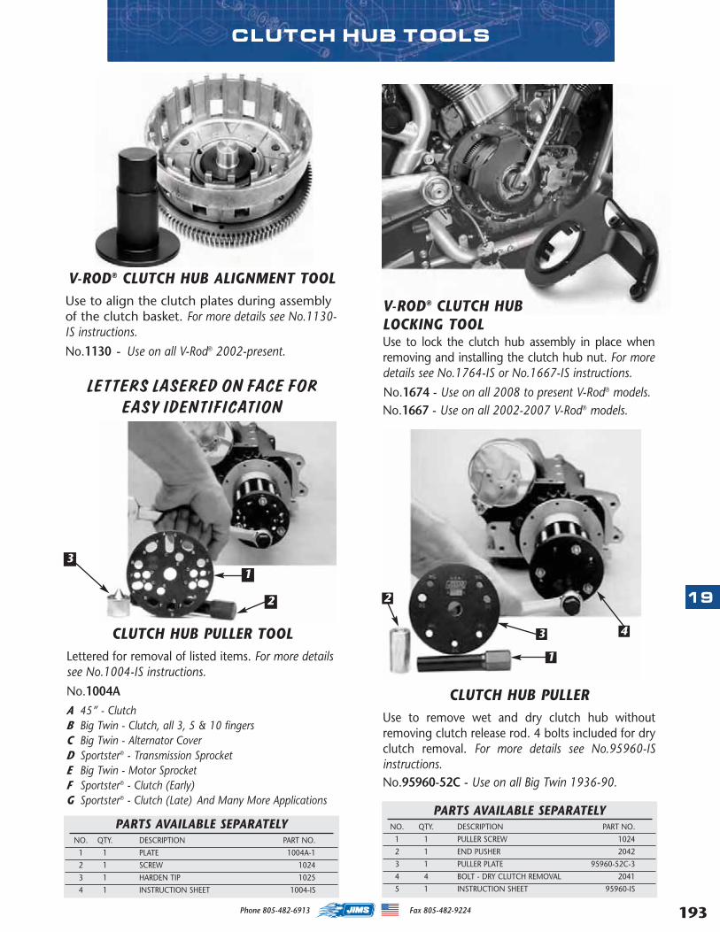
PARTS AVAILABLE SEPARATELYNO. QTY. DESCRIPTION PART NO.
1 1 PULLER SCREW 1024
2 1 END PUSHER 2042
3 1 PULLER PLATE 95960-52C-3
4 4 BOLT - DRY CLUTCH REMOVAL 2041
5 1 INSTRUCTION SHEET 95960-IS
A 45” - ClutchB Big Twin - Clutch, all 3, 5 & 10 fingersC Big Twin - Alternator CoverD Sportster® - Transmission SprocketE Big Twin - Motor SprocketF Sportster® - Clutch (Early)G Sportster® - Clutch (Late) And Many More Applications
CLUTCH HUB PULLER TOOLLettered for removal of listed items. For more detailssee No.1004-IS instructions.
No.1004A
LETTERS LASERED ON FACE FOR EASY IDENTIFICATION
CLUTCH HUB PULLERUse to remove wet and dry clutch hub withoutremoving clutch release rod. 4 bolts included for dryclutch removal. For more details see No.95960-ISinstructions.No.95960-52C - Use on all Big Twin 1936-90.
V-ROD® CLUTCH HUB ALIGNMENT TOOLUse to align the clutch plates during assemblyof the clutch basket. For more details see No.1130-IS instructions.
No.1130 - Use on all V-Rod® 2002-present.
PARTS AVAILABLE SEPARATELYNO. QTY. DESCRIPTION PART NO.
1 1 PLATE 1004A-1
2 1 SCREW 1024
3 1 HARDEN TIP 1025
4 1 INSTRUCTION SHEET 1004-IS
1
2
3
1
2
3 4
CLUTCH HUB TOOLS
V-ROD® CLUTCH HUB LOCKING TOOLUse to lock the clutch hub assembly in place whenremoving and installing the clutch hub nut. For moredetails see No.1764-IS or No.1667-IS instructions.
No.1674 - Use on all 2008 to present V-Rod® models.No.1667 - Use on all 2002-2007 V-Rod® models.
19
193Phone 805-482-6913 Fax 805-482-9224
MASTER 2013 CATALOG_JMS 2.qxp:Layout 1 8/2/12 8:30 PM Page 193
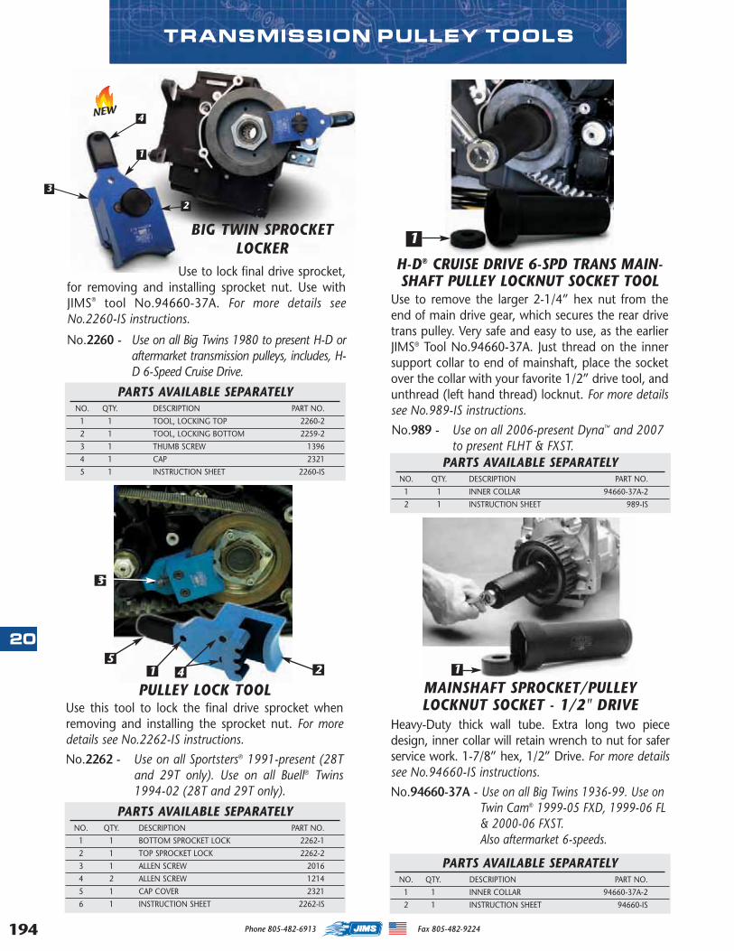
194
20
PULLEY LOCK TOOLUse this tool to lock the final drive sprocket whenremoving and installing the sprocket nut. For moredetails see No.2262-IS instructions.
No.2262 - Use on all Sportsters® 1991-present (28Tand 29T only). Use on all Buell® Twins1994-02 (28T and 29T only).
4
3
25
1
PARTS AVAILABLE SEPARATELYNO. QTY. DESCRIPTION PART NO.
1 1 BOTTOM SPROCKET LOCK 2262-1
2 1 TOP SPROCKET LOCK 2262-2
3 1 ALLEN SCREW 2016
4 2 ALLEN SCREW 1214
5 1 CAP COVER 2321
6 1 INSTRUCTION SHEET 2262-IS
BIG TWIN SPROCKETLOCKER
Use to lock final drive sprocket,for removing and installing sprocket nut. Use withJIMS® tool No.94660-37A. For more details seeNo.2260-IS instructions.
No.2260 - Use on all Big Twins 1980 to present H-D oraftermarket transmission pulleys, includes, H-D 6-Speed Cruise Drive.
2
4
PARTS AVAILABLE SEPARATELYNO. QTY. DESCRIPTION PART NO.
1 1 TOOL, LOCKING TOP 2260-2
2 1 TOOL, LOCKING BOTTOM 2259-2
3 1 THUMB SCREW 1396
4 1 CAP 2321
5 1 INSTRUCTION SHEET 2260-IS
TRANSMISSION PULLEY TOOLS
MAINSHAFT SPROCKET/PULLEY LOCKNUT SOCKET - 1/2" DRIVE
Heavy-Duty thick wall tube. Extra long two piecedesign, inner collar will retain wrench to nut for saferservice work. 1-7/8” hex, 1/2” Drive. For more detailssee No.94660-IS instructions.
No.94660-37A - Use on all Big Twins 1936-99. Use onTwin Cam® 1999-05 FXD, 1999-06 FL& 2000-06 FXST.Also aftermarket 6-speeds.
1
H-D® CRUISE DRIVE 6-SPD TRANS MAIN-SHAFT PULLEY LOCKNUT SOCKET TOOL
Use to remove the larger 2-1/4” hex nut from theend of main drive gear, which secures the rear drivetrans pulley. Very safe and easy to use, as the earlierJIMS® Tool No.94660-37A. Just thread on the innersupport collar to end of mainshaft, place the socketover the collar with your favorite 1/2” drive tool, andunthread (left hand thread) locknut. For more detailssee No.989-IS instructions.
No.989 - Use on all 2006-present Dyna™ and 2007to present FLHT & FXST.
1
PARTS AVAILABLE SEPARATELYNO. QTY. DESCRIPTION PART NO.
1 1 INNER COLLAR 94660-37A-2
2 1 INSTRUCTION SHEET 94660-IS
PARTS AVAILABLE SEPARATELYNO. QTY. DESCRIPTION PART NO.
1 1 INNER COLLAR 94660-37A-2
2 1 INSTRUCTION SHEET 989-IS
3
1
NEW
Phone 805-482-6913 Fax 805-482-9224
MASTER 2013 CATALOG_JMS 2.qxp:Layout 1 8/2/12 8:30 PM Page 194
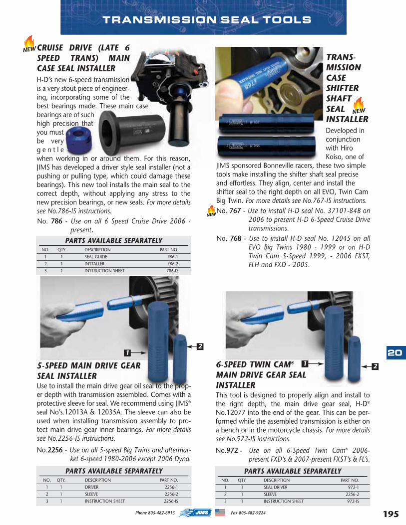
NEWCRUISE DRIVE (LATE 6SPEED TRANS) MAINCASE SEAL INSTALLERH-D’s new 6-speed transmissionis a very stout piece of engineer-ing, incorporating some of thebest bearings made. These main casebearings are of suchhigh precision thatyou mustbe veryg e n t l ewhen working in or around them. For this reason,JIMS has developed a driver style seal installer (not apushing or pulling type, which could damage thesebearings). This new tool installs the main seal to thecorrect depth, without applying any stress to thenew precision bearings, or new seals. For more detailssee No.786-IS instructions.No. 786 - Use on all 6 Speed Cruise Drive 2006 -
present.PARTS AVAILABLE SEPARATELY
NO. QTY. DESCRIPTION PART NO.
1 1 SEAL GUIDE 786-1
2 1 INSTALLER 786-2
3 1 INSTRUCTION SHEET 786-IS
TRANS-MISSIONCASESHIFTERSHAFTSEALINSTALLERDeveloped inconjunctionwith HiroKoiso, one of
JIMS sponsored Bonneville racers, these two simpletools make installing the shifter shaft seal preciseand effortless. They align, center and install theshifter seal to the right depth on all EVO, Twin CamBig Twin. For more details see No.767-IS instructions.No. 767 - Use to install H-D seal No. 37101-84B on
2006 to present H-D 6-Speed Cruise Drivetransmissions.
No. 768 - Use to install H-D seal No. 12045 on allEVO Big Twins 1980 - 1999 or on H-DTwin Cam 5-Speed 1999, - 2006 FXST,FLH and FXD - 2005.
6-SPEED TWIN CAM®
MAIN DRIVE GEAR SEALINSTALLERThis tool is designed to properly align and install tothe right depth, the main drive gear seal, H-D®
No.12077 into the end of the gear. This can be per-formed while the assembled transmission is either ona bench or in the motorcycle chassis. For more detailssee No.972-IS instructions.
No.972 - Use on all 6-Speed Twin Cam® 2006-present FXD’s & 2007-present FXST’s & FL’s.
PARTS AVAILABLE SEPARATELYNO. QTY. DESCRIPTION PART NO.
1 1 SEAL DRIVER 972-1
2 1 SLEEVE 2256-2
3 1 INSTRUCTION SHEET 972-IS
1 25-SPEED MAIN DRIVE GEAR SEAL INSTALLERUse to install the main drive gear oil seal to the prop-er depth with transmission assembled. Comes with aprotective sleeve for seal. We recommend using JIMS®
seal No’s.12013A & 12035A. The sleeve can also beused when installing transmission assembly to pro-tect main drive gear inner bearings. For more detailssee No.2256-IS instructions.
No.2256 - Use on all 5-speed Big Twins and aftermar-ket 6-speed 1980-2006 except 2006 Dyna.
PARTS AVAILABLE SEPARATELYNO. QTY. DESCRIPTION PART NO.
1 1 DRIVER 2256-1
2 1 SLEEVE 2256-2
3 1 INSTRUCTION SHEET 2256-IS
12
TRANSMISSION SEAL TOOLS
NEW
NEW
20
195Phone 805-482-6913 Fax 805-482-9224
MASTER 2013 CATALOG_JMS 2.qxp:Layout 1 8/2/12 8:30 PM Page 195
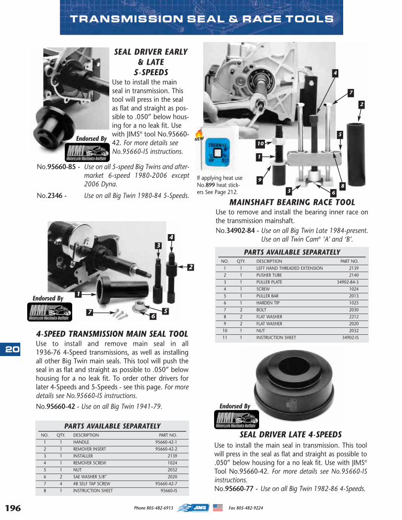
196
20
MAINSHAFT BEARING RACE TOOLUse to remove and install the bearing inner race onthe transmission mainshaft.No.34902-84 - Use on all Big Twin Late 1984-present.
Use on all Twin Cam® ‘A’ and ‘B’.
4
5
6
7
89
10
1
2
3
PARTS AVAILABLE SEPARATELYNO. QTY. DESCRIPTION PART NO.
1 1 LEFT HAND THREADED EXTENSION 2139
2 1 PUSHER TUBE 2140
3 1 PULLER PLATE 34902-84-3
4 1 SCREW 1024
5 1 PULLER BAR 2013
6 1 HARDEN TIP 1025
7 2 BOLT 2030
8 2 FLAT WASHER 2212
9 2 FLAT WASHER 2020
10 1 NUT 2032
11 1 INSTRUCTION SHEET 34902-IS4-SPEED TRANSMISSION MAIN SEAL TOOLUse to install and remove main seal in all 1936-76 4-Speed transmissions, as well as installingall other Big Twin main seals. This tool will push theseal in as flat and straight as possible to .050” belowhousing for a no leak fit. To order other drivers forlater 4-Speeds and 5-Speeds - see this page. For moredetails see No.95660-IS instructions.
No.95660-42 - Use on all Big Twin 1941-79.
SEAL DRIVER EARLY& LATE
5-SPEEDSUse to install the mainseal in transmission. Thistool will press in the sealas flat and straight as pos-sible to .050” below hous-ing for a no leak fit. Usewith JIMS® tool No.95660-42. For more details seeNo.95660-IS instructions.
Endorsed By
Endorsed By
No.95660-85 - Use on all 5-speed Big Twins and after-market 6-speed 1980-2006 except2006 Dyna.
No.2346 - Use on all Big Twin 1980-84 5-Speeds.
PARTS AVAILABLE SEPARATELYNO. QTY. DESCRIPTION PART NO.
1 1 HANDLE 95660-42-1
2 1 REMOVER INSERT 95660-42-2
3 1 INSTALLER 2139
4 1 REMOVER SCREW 1024
5 1 NUT 2032
6 2 SAE WASHER 5/8” 2020
7 4 #8 SELF TAP SCREW 95660-42-7
8 1 INSTRUCTION SHEET 95660-IS
1
2
34
56
7
Use to install the main seal in transmission. This toolwill press in the seal as flat and straight as possible to.050” below housing for a no leak fit. Use with JIMS®
Tool No.95660-42. For more details see No.95660-ISinstructions.No.95660-77 - Use on all Big Twin 1982-86 4-Speeds.
Endorsed By
SEAL DRIVER LATE 4-SPEEDS
If applying heat useNo.899 heat stick-ers See Page 212.
TRANSMISSION SEAL & RACE TOOLS
NEW
Phone 805-482-6913 Fax 805-482-9224
MASTER 2013 CATALOG_JMS 2.qxp:Layout 1 8/2/12 8:30 PM Page 196
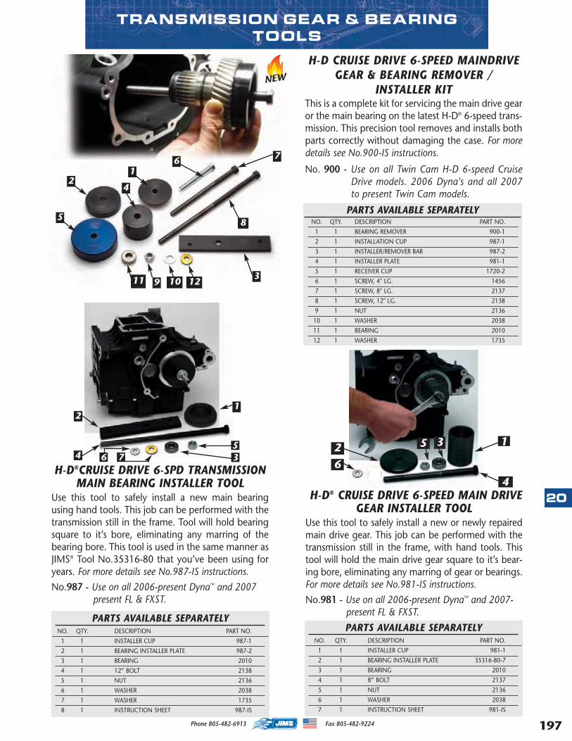
H-D CRUISE DRIVE 6-SPEED MAINDRIVEGEAR & BEARING REMOVER /
INSTALLER KITThis is a complete kit for servicing the main drive gearor the main bearing on the latest H-D® 6-speed trans-mission. This precision tool removes and installs bothparts correctly without damaging the case. For moredetails see No.900-IS instructions.
No. 900 - Use on all Twin Cam H-D 6-speed CruiseDrive models. 2006 Dyna's and all 2007to present Twin Cam models.
TRANSMISSION GEAR & BEARINGTOOLS
H-D®CRUISE DRIVE 6-SPD TRANSMISSIONMAIN BEARING INSTALLER TOOL
Use this tool to safely install a new main bearingusing hand tools. This job can be performed with thetransmission still in the frame. Tool will hold bearingsquare to it’s bore, eliminating any marring of thebearing bore. This tool is used in the same manner asJIMS® Tool No.35316-80 that you’ve been using foryears. For more details see No.987-IS instructions.
No.987 - Use on all 2006-present Dyna™ and 2007present FL & FXST.
PARTS AVAILABLE SEPARATELYNO. QTY. DESCRIPTION PART NO.
1 1 INSTALLER CUP 987-1
2 1 BEARING INSTALLER PLATE 987-2
3 1 BEARING 2010
4 1 12” BOLT 2138
5 1 NUT 2136
6 1 WASHER 2038
7 1 WASHER 1735
8 1 INSTRUCTION SHEET 987-IS
2
3
1
54
H-D® CRUISE DRIVE 6-SPEED MAIN DRIVEGEAR INSTALLER TOOL
Use this tool to safely install a new or newly repairedmain drive gear. This job can be performed with thetransmission still in the frame, with hand tools. Thistool will hold the main drive gear square to it’s bear-ing bore, eliminating any marring of gear or bearings.For more details see No.981-IS instructions.
No.981 - Use on all 2006-present Dyna™ and 2007- present FL & FXST.
4
2 3 15
12
5
11 9 103
8
76
4
PARTS AVAILABLE SEPARATELYNO. QTY. DESCRIPTION PART NO.
1 1 INSTALLER CUP 981-1
2 1 BEARING INSTALLER PLATE 35316-80-7
3 1 BEARING 2010
4 1 8” BOLT 2137
5 1 NUT 2136
6 1 WASHER 2038
7 1 INSTRUCTION SHEET 981-IS
NEW
PARTS AVAILABLE SEPARATELYNO. QTY. DESCRIPTION PART NO.
1 1 BEARING REMOVER 900-1
2 1 INSTALLATION CUP 987-1
3 1 INSTALLER/REMOVER BAR 987-2
4 1 INSTALLER PLATE 981-1
5 1 RECEIVER CUP 1720-2
6 1 SCREW, 4" LG. 1456
7 1 SCREW, 8" LG. 2137
8 1 SCREW, 12" LG. 2138
9 1 NUT 2136
10 1 WASHER 2038
11 1 BEARING 2010
12 1 WASHER 1735
12
76
36
20
197Phone 805-482-6913 Fax 805-482-9224
MASTER 2013 CATALOG_JMS 2.qxp:Layout 1 8/2/12 8:30 PM Page 197
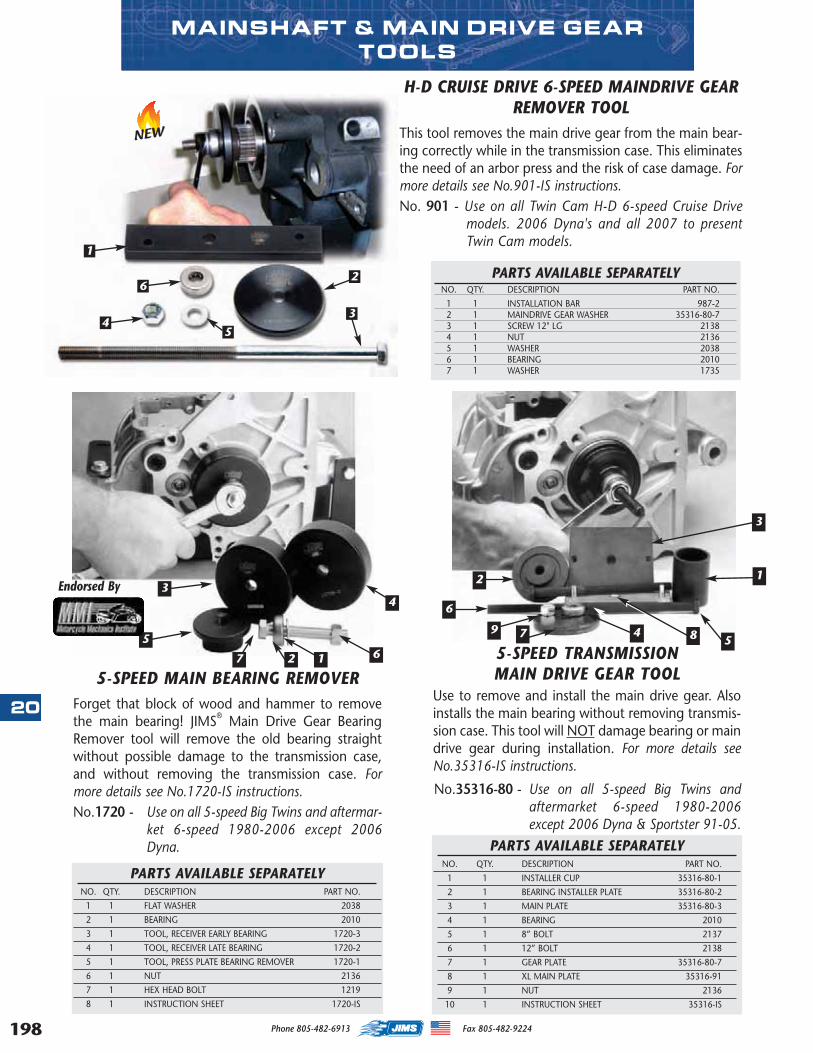
198
20
5-SPEED TRANSMISSION MAIN DRIVE GEAR TOOL
Use to remove and install the main drive gear. Alsoinstalls the main bearing without removing transmis-sion case. This tool will NOT damage bearing or maindrive gear during installation. For more details seeNo.35316-IS instructions.
No.35316-80 - Use on all 5-speed Big Twins andaftermarket 6-speed 1980-2006except 2006 Dyna & Sportster 91-05.
PARTS AVAILABLE SEPARATELYNO. QTY. DESCRIPTION PART NO.
1 1 INSTALLER CUP 35316-80-1
2 1 BEARING INSTALLER PLATE 35316-80-2
3 1 MAIN PLATE 35316-80-3
4 1 BEARING 2010
5 1 8” BOLT 2137
6 1 12” BOLT 2138
7 1 GEAR PLATE 35316-80-7
8 1 XL MAIN PLATE 35316-91
9 1 NUT 2136
10 1 INSTRUCTION SHEET 35316-IS
PARTS AVAILABLE SEPARATELYNO. QTY. DESCRIPTION PART NO.
1 1 FLAT WASHER 2038
2 1 BEARING 2010
3 1 TOOL, RECEIVER EARLY BEARING 1720-3
4 1 TOOL, RECEIVER LATE BEARING 1720-2
5 1 TOOL, PRESS PLATE BEARING REMOVER 1720-1
6 1 NUT 2136
7 1 HEX HEAD BOLT 1219
8 1 INSTRUCTION SHEET 1720-IS
5-SPEED MAIN BEARING REMOVERForget that block of wood and hammer to removethe main bearing! JIMS® Main Drive Gear BearingRemover tool will remove the old bearing straightwithout possible damage to the transmission case,and without removing the transmission case. Formore details see No.1720-IS instructions.No.1720 - Use on all 5-speed Big Twins and aftermar-
ket 6-speed 1980-2006 except 2006Dyna.
Endorsed By12
3
5
6
79
12
34
567
4 8
H-D CRUISE DRIVE 6-SPEED MAINDRIVE GEARREMOVER TOOL
This tool removes the main drive gear from the main bear-ing correctly while in the transmission case. This eliminatesthe need of an arbor press and the risk of case damage. Formore details see No.901-IS instructions.No. 901 - Use on all Twin Cam H-D 6-speed Cruise Drive
models. 2006 Dyna's and all 2007 to presentTwin Cam models.
MAINSHAFT & MAIN DRIVE GEARTOOLS
1
6
4
2
3
5
PARTS AVAILABLE SEPARATELYNO. QTY. DESCRIPTION PART NO.
1 1 INSTALLATION BAR 987-22 1 MAINDRIVE GEAR WASHER 35316-80-73 1 SCREW 12" LG 2138 4 1 NUT 21365 1 WASHER 2038 6 1 BEARING 20107 1 WASHER 1735
NEW
Phone 805-482-6913 Fax 805-482-9224
MASTER 2013 CATALOG_JMS 2.qxp:Layout 1 8/2/12 8:31 PM Page 198
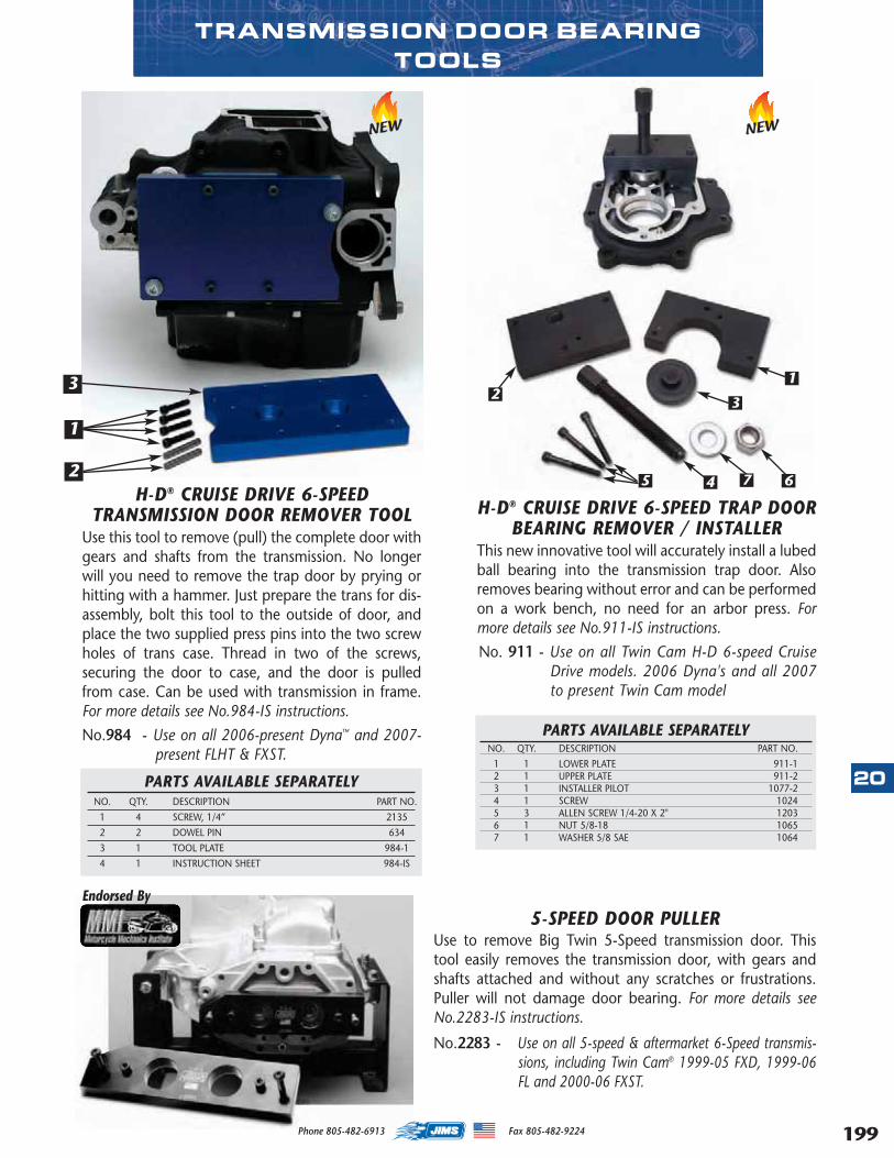
H-D® CRUISE DRIVE 6-SPEEDTRANSMISSION DOOR REMOVER TOOL
Use this tool to remove (pull) the complete door withgears and shafts from the transmission. No longerwill you need to remove the trap door by prying orhitting with a hammer. Just prepare the trans for dis-assembly, bolt this tool to the outside of door, andplace the two supplied press pins into the two screwholes of trans case. Thread in two of the screws,securing the door to case, and the door is pulledfrom case. Can be used with transmission in frame.For more details see No.984-IS instructions.
No.984 - Use on all 2006-present Dyna™ and 2007-present FLHT & FXST.
1
2
PARTS AVAILABLE SEPARATELYNO. QTY. DESCRIPTION PART NO.
1 4 SCREW, 1/4” 2135
2 2 DOWEL PIN 634
3 1 TOOL PLATE 984-1
4 1 INSTRUCTION SHEET 984-IS
TRANSMISSION DOOR BEARING TOOLS
H-D® CRUISE DRIVE 6-SPEED TRAP DOORBEARING REMOVER / INSTALLER
This new innovative tool will accurately install a lubedball bearing into the transmission trap door. Alsoremoves bearing without error and can be performedon a work bench, no need for an arbor press. Formore details see No.911-IS instructions.
No. 911 - Use on all Twin Cam H-D 6-speed CruiseDrive models. 2006 Dyna's and all 2007to present Twin Cam model
3
PARTS AVAILABLE SEPARATELYNO. QTY. DESCRIPTION PART NO.
1 1 LOWER PLATE 911-12 1 UPPER PLATE 911-2 3 1 INSTALLER PILOT 1077-24 1 SCREW 10245 3 ALLEN SCREW 1/4-20 X 2" 1203 6 1 NUT 5/8-18 10657 1 WASHER 5/8 SAE 1064
2
5 4 7 6
3
1
5-SPEED DOOR PULLERUse to remove Big Twin 5-Speed transmission door. Thistool easily removes the transmission door, with gears andshafts attached and without any scratches or frustrations.Puller will not damage door bearing. For more details seeNo.2283-IS instructions.
No.2283 - Use on all 5-speed & aftermarket 6-Speed transmis-sions, including Twin Cam® 1999-05 FXD, 1999-06FL and 2000-06 FXST.
Endorsed By
NEW NEW
20
199Phone 805-482-6913 Fax 805-482-9224
MASTER 2013 CATALOG_JMS 2.qxp:Layout 1 8/2/12 8:31 PM Page 199
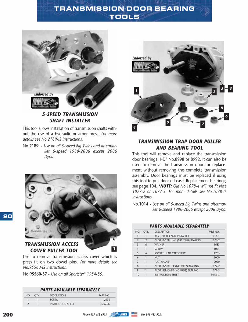
200
20
TRANSMISSION DOOR BEARING TOOLS
5-SPEED TRANSMISSION SHAFT INSTALLER
This tool allows installation of transmission shafts with-out the use of a hydraulic or arbor press. For moredetails see No.2189-IS instructions.
No.2189 - Use on all 5-speed Big Twins and aftermar-ket 6-speed 1980-2006 except 2006Dyna.
TRANSMISSION ACCESSCOVER PULLER TOOL
Use to remove transmission access cover which ispress fit on two dowel pins. For more details seeNo.95560-IS instructions.
No.95560-57 - Use on all Sportster® 1954-85.
Endorsed By
Endorsed By
TRANSMISSION TRAP DOOR PULLERAND BEARING TOOL
This tool will remove and replace the transmissiondoor bearings H-D® No.8998 or 8992. It can also beused to remove the transmission door for replace-ment without removing the complete transmissionassembly. Door bearings must be replaced if usingthis tool to pull door off case. Replacement bearings;see page 104. *NOTE: Old No.1078-4 will not fit No’s1077-2 or 1077-3. For more details see No.1078-ISinstructions.
No.1014 - Use on all 5-speed Big Twins and aftermar-ket 6-speed 1980-2006 except 2006 Dyna.
1
1 2
4
PARTS AVAILABLE SEPARATELYNO. QTY. DESCRIPTION PART NO.
1 1 SCREW 2130
2 1 INSTRUCTION SHEET 95560-IS
PARTS AVAILABLE SEPARATELYNO. QTY. DESCRIPTION PART NO.
1 1 BASE, PULLER AND INSTALLER 1014-1
2 2 PILOT, INSTALLING (NO.8998) BEARING 1078-2
3 6 WASHER 1683
4 1 SCREW 1024
5 6 SOCKET HEAD CAP SCREW 1203
6 1 NUT 2000
7 1 FLAT WASHER 2020
8 1 PILOT, INSTALLER (NO.8992) BEARING 1077-2
9 1 PILOT, REMOVER (NO.8992) BEARING 1077-3
10 1 INSTRUCTION SHEET 1078-IS
8
9
6
7
35
Phone 805-482-6913 Fax 805-482-9224
MASTER 2013 CATALOG_JMS 2.qxp:Layout 1 8/2/12 8:31 PM Page 200
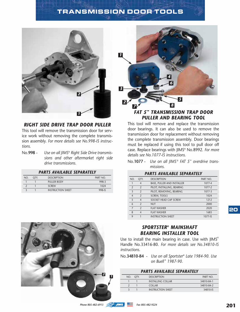
TRANSMISSION DOOR TOOLS
FAT 5™ TRANSMISSION TRAP DOORPULLER AND BEARING TOOL
This tool will remove and replace the transmissiondoor bearings. It can also be used to remove thetransmission door for replacement without removingthe complete transmission assembly. Door bearingsmust be replaced if using this tool to pull door offcase. Replace bearings with JIMS® No.8992. For moredetails see No.1077-IS instructions.
No.1077 - Use on all JIMS ® FAT 5™ overdrive trans-missions.
PARTS AVAILABLE SEPARATELYNO. QTY. DESCRIPTION PART NO.
1 4 BASE, PULLER AND INSTALLER 1077-4
2 2 PILOT, INSTALLING, BEARING 1077-2
3 2 PILOT, REMOVING, BEARING 1077-3
4 2 SCREW, TOOLS 1024
5 4 SOCKET HEAD CAP SCREW 1212
6 2 NUT 2000
7 2 FLAT WASHER 2020
8 4 FLAT WASHER 1683
9 1 INSTRUCTION SHEET 1077-IS
2
3
1
7
4
6
85
RIGHT SIDE DRIVE TRAP DOOR PULLERThis tool will remove the transmission door for serv-ice work without removing the complete transmis-sion assembly. For more details see No.998-IS instruc-tions.
No.998 - Use on all JIMS® Right Side Drive transmis-sions and other aftermarket right sidedrive transmissions.
1
2
PARTS AVAILABLE SEPARATELYNO. QTY. DESCRIPTION PART NO.
1 1 PULLER BODY 998-3
2 1 SCREW 1024
3 1 INSTRUCTION SHEET 998-IS
SPORTSTER® MAINSHAFT BEARING INSTALLER TOOL
Use to install the main bearing in case. Use with JIMS®
Handle No.33416-80. For more details see No.34810-ISinstructions.
No.34810-84 - Use on all Sportster® Late 1984-90. Useon Buell ® 1987-90.
12
PARTS AVAILABLE SEPARATELYNO. QTY. DESCRIPTION PART NO.
1 1 INSTALLING COLLAR 34810-84-1
2 1 COLLAR 34810-84-2
3 1 INSTRUCTION SHEET 34810-IS
20
201Phone 805-482-6913 Fax 805-482-9224
MASTER 2013 CATALOG_JMS 2.qxp:Layout 1 8/2/12 8:31 PM Page 201

202
20
5-SPEEDMAINDRIVEGEAR BEARING& SEALINSTALLERUse to install bothbearings and the seal on the clutch side. For moredetails see No.34734-IS instructions.No.34734-80 - Use on all Big Twin 5-speed 1980-
1990.
MAINDRIVE GEAR TOOLS
MAIN DRIVE GEAR BEARING TOOLUse to install inner and outer 5th gear bearings to facto-ry depth. New bearing depth incorporated, will stillwork on early depth. For more details see No.37842-ISinstructions.
No.37842-91 - Use on all 5-speed Big Twins andaftermarket 6-speed 1980-2006except 2006 Dyna. Use on Sportsteror Buell 1991 - 2005.
H-D® CRUISE DRIVE 6-SPEEDMAIN DRIVE GEAR,
BEARING & SEAL INSTALLER TOOLUse this tool to safely install new main drive gearbearings and seal. This tool will hold bearings andseal square to it’s bore, eliminating any marring ofthe bearings and seals and installing both to the rightdepth. This tool is used in the same manner as JIMS®
Tool No.37842-91 that you’ve used for years. Formore details see No.986-IS instructions.
No.986 - Use on all 2006-present Dyna™ and 2007-present FL & FXST.
2 1
PARTS AVAILABLE SEPARATELYNO. QTY. DESCRIPTION PART NO.
1 1 BEARING REMOVER 986-1
2 1 SEAL INSTALLER 986-2
3 1 INSTRUCTION SHEET 986-IS
MAIN DRIVE GEAR BUSHING TOOLUse to remove and install the main drive gear bush-ings, also to remove Big Twin cam bushing 1970-present. For more details see No.1005-IS instructions.No.1005 - Use on all Big Twin 1936-86 4-Speeds.
PARTS AVAILABLE SEPARATELYNO. QTY. DESCRIPTION PART NO.
1 1 DRIVER 1005-1
2 1 SLEEVE 1005-2
3 1 INSTRUCTION SHEET 1005-IS
1
2
TRANSMISSION MAIN DRIVEGEAR BEARING TOOL
Use to install main bearing H-D No.8905 or No.8906to the factory depth. For more details see No.33428-IS instructions.No.33428-78 - Use on all Big Twin 1979-85 4-Speed.
Phone 805-482-6913 Fax 805-482-9224
MASTER 2013 CATALOG_JMS 2.qxp:Layout 1 8/2/12 8:31 PM Page 202
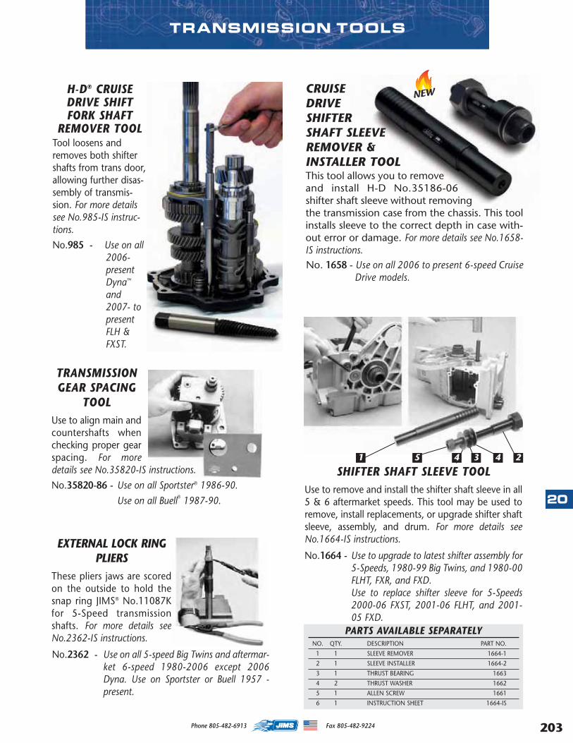
TRANSMISSION TOOLS
EXTERNAL LOCK RINGPLIERS
These pliers jaws are scoredon the outside to hold thesnap ring JIMS® No.11087Kfor 5-Speed transmissionshafts. For more details seeNo.2362-IS instructions.
No.2362 - Use on all 5-speed Big Twins and aftermar-ket 6-speed 1980-2006 except 2006Dyna. Use on Sportster or Buell 1957 -present.
SHIFTER SHAFT SLEEVE TOOLUse to remove and install the shifter shaft sleeve in all5 & 6 aftermarket speeds. This tool may be used toremove, install replacements, or upgrade shifter shaftsleeve, assembly, and drum. For more details seeNo.1664-IS instructions.
No.1664 - Use to upgrade to latest shifter assembly for5-Speeds, 1980-99 Big Twins, and 1980-00FLHT, FXR, and FXD.Use to replace shifter sleeve for 5-Speeds2000-06 FXST, 2001-06 FLHT, and 2001-05 FXD.
PARTS AVAILABLE SEPARATELYNO. QTY. DESCRIPTION PART NO.
1 1 SLEEVE REMOVER 1664-1
2 1 SLEEVE INSTALLER 1664-2
3 1 THRUST BEARING 1663
4 2 THRUST WASHER 1662
5 1 ALLEN SCREW 1661
6 1 INSTRUCTION SHEET 1664-IS
1 45 4 3 2
TRANSMISSIONGEAR SPACING
TOOLUse to align main andcountershafts whenchecking proper gearspacing. For moredetails see No.35820-IS instructions.
No.35820-86 - Use on all Sportster® 1986-90.
Use on all Buell® 1987-90.
H-D® CRUISEDRIVE SHIFTFORK SHAFT
REMOVER TOOLTool loosens andremoves both shiftershafts from trans door,allowing further disas-sembly of transmis-sion. For more detailssee No.985-IS instruc-tions.
No.985 - Use on all2006-presentDyna™
and2007- topresentFLH &FXST.
CRUISEDRIVESHIFTERSHAFT SLEEVE REMOVER &INSTALLER TOOLThis tool allows you to removeand install H-D No.35186-06shifter shaft sleeve without removingthe transmission case from the chassis. This toolinstalls sleeve to the correct depth in case with-out error or damage. For more details see No.1658-IS instructions.No. 1658 - Use on all 2006 to present 6-speed Cruise
Drive models.
NEW
20
203Phone 805-482-6913 Fax 805-482-9224
MASTER 2013 CATALOG_JMS 2.qxp:Layout 1 8/2/12 8:31 PM Page 203
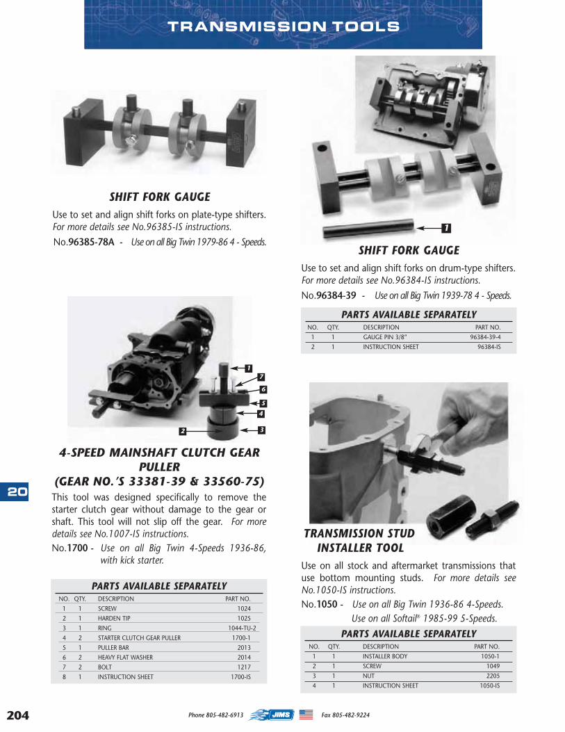
204
20
TRANSMISSION TOOLS
PARTS AVAILABLE SEPARATELYNO. QTY. DESCRIPTION PART NO.
1 1 SCREW 1024
2 1 HARDEN TIP 1025
3 1 RING 1044-TU-2
4 2 STARTER CLUTCH GEAR PULLER 1700-1
5 1 PULLER BAR 2013
6 2 HEAVY FLAT WASHER 2014
7 2 BOLT 1217
8 1 INSTRUCTION SHEET 1700-IS
4-SPEED MAINSHAFT CLUTCH GEARPULLER
(GEAR NO.’S 33381-39 & 33560-75)This tool was designed specifically to remove thestarter clutch gear without damage to the gear orshaft. This tool will not slip off the gear. For moredetails see No.1007-IS instructions.No.1700 - Use on all Big Twin 4-Speeds 1936-86,
with kick starter.
1
2 3
4
5
6
7
SHIFT FORK GAUGEUse to set and align shift forks on drum-type shifters.For more details see No.96384-IS instructions.
No.96384-39 - Use on all Big Twin 1939-78 4 - Speeds.
SHIFT FORK GAUGEUse to set and align shift forks on plate-type shifters.For more details see No.96385-IS instructions.
No.96385-78A - Use on all Big Twin 1979-86 4 - Speeds.
TRANSMISSION STUDINSTALLER TOOL
Use on all stock and aftermarket transmissions thatuse bottom mounting studs. For more details seeNo.1050-IS instructions.No.1050 - Use on all Big Twin 1936-86 4-Speeds.
Use on all Softail® 1985-99 5-Speeds.
PARTS AVAILABLE SEPARATELYNO. QTY. DESCRIPTION PART NO.
1 1 INSTALLER BODY 1050-1
2 1 SCREW 1049
3 1 NUT 2205
4 1 INSTRUCTION SHEET 1050-IS
PARTS AVAILABLE SEPARATELYNO. QTY. DESCRIPTION PART NO.
1 1 GAUGE PIN 3/8” 96384-39-4
2 1 INSTRUCTION SHEET 96384-IS
1
Phone 805-482-6913 Fax 805-482-9224
MASTER 2013 CATALOG_JMS 2.qxp:Layout 1 8/2/12 8:31 PM Page 204
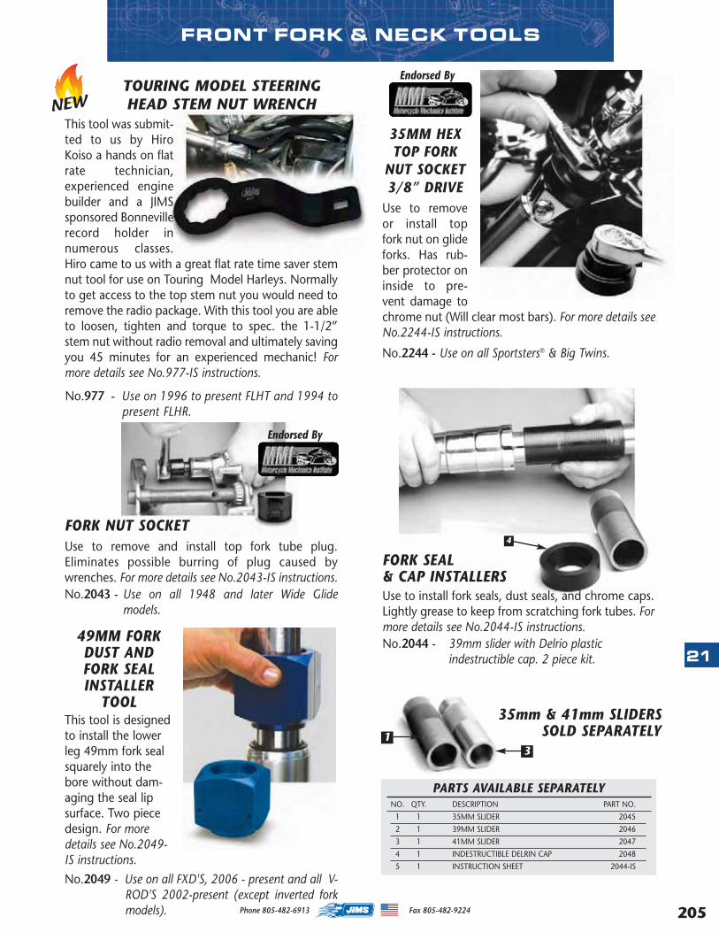
FRONT FORK & NECK TOOLS
35MM HEXTOP FORK
NUT SOCKET3/8” DRIVE
Use to removeor install topfork nut on glideforks. Has rub-ber protector oninside to pre-vent damage tochrome nut (Will clear most bars). For more details seeNo.2244-IS instructions.
No.2244 - Use on all Sportsters® & Big Twins.
Endorsed By
Endorsed By
49MM FORKDUST ANDFORK SEALINSTALLER
TOOLThis tool is designedto install the lowerleg 49mm fork sealsquarely into thebore without dam-aging the seal lipsurface. Two piecedesign. For moredetails see No.2049-IS instructions.
No.2049 - Use on all FXD'S, 2006 - present and all V-ROD'S 2002-present (except inverted forkmodels).
PARTS AVAILABLE SEPARATELYNO. QTY. DESCRIPTION PART NO.
1 1 35MM SLIDER 2045
2 1 39MM SLIDER 2046
3 1 41MM SLIDER 2047
4 1 INDESTRUCTIBLE DELRIN CAP 2048
5 1 INSTRUCTION SHEET 2044-IS
FORK SEAL & CAP INSTALLERSUse to install fork seals, dust seals, and chrome caps.Lightly grease to keep from scratching fork tubes. Formore details see No.2044-IS instructions.No.2044 - 39mm slider with Delrio plastic
indestructible cap. 2 piece kit.
35mm & 41mm SLIDERSSOLD SEPARATELY
FORK NUT SOCKETUse to remove and install top fork tube plug.Eliminates possible burring of plug caused bywrenches. For more details see No.2043-IS instructions.No.2043 - Use on all 1948 and later Wide Glide
models.
13
4
TOURING MODEL STEERINGHEAD STEM NUT WRENCH
This tool was submit-ted to us by HiroKoiso a hands on flatrate technician,experienced enginebuilder and a JIMSsponsored Bonnevillerecord holder innumerous classes.Hiro came to us with a great flat rate time saver stemnut tool for use on Touring Model Harleys. Normallyto get access to the top stem nut you would need toremove the radio package. With this tool you are ableto loosen, tighten and torque to spec. the 1-1/2”stem nut without radio removal and ultimately savingyou 45 minutes for an experienced mechanic! Formore details see No.977-IS instructions.
No.977 - Use on 1996 to present FLHT and 1994 topresent FLHR.
NEW
21
205Phone 805-482-6913 Fax 805-482-9224
MASTER 2013 CATALOG_JMS 2.qxp:Layout 1 8/2/12 8:31 PM Page 205
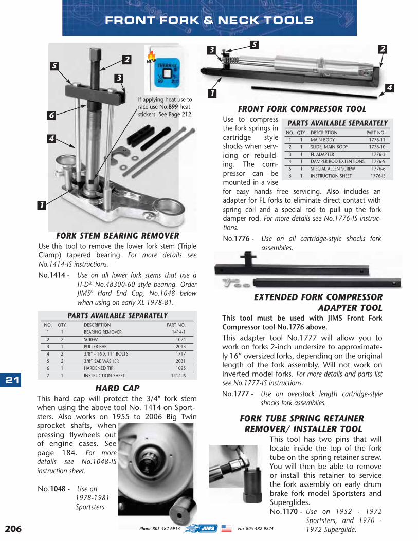
206
21HARD CAP
This hard cap will protect the 3/4" fork stemwhen using the above tool No. 1414 on Sport-sters. Also works on 1955 to 2006 Big Twinsprocket shafts, whenpressing flywheels outof engine cases. Seepage 184. For moredetails see No.1048-ISinstruction sheet.
No.1048 - Use on1978-1981Sportsters
PARTS AVAILABLE SEPARATELYNO. QTY. DESCRIPTION PART NO.
1 1 BEARING REMOVER 1414-1
2 2 SCREW 1024
3 1 PULLER BAR 2013
4 2 3/8” - 16 X 11” BOLTS 1717
5 2 3/8” SAE WASHER 2031
6 1 HARDENED TIP 1025
7 1 INSTRUCTION SHEET 1414-IS
FORK STEM BEARING REMOVERUse this tool to remove the lower fork stem (TripleClamp) tapered bearing. For more details seeNo.1414-IS instructions.
No.1414 - Use on all lower fork stems that use aH-D® No.48300-60 style bearing. OrderJIMS® Hard End Cap, No.1048 belowwhen using on early XL 1978-81.
2
3
1
5
6
4
FORK TUBE SPRING RETAINERREMOVER/ INSTALLER TOOL
This tool has two pins that willlocate inside the top of the forktube on the spring retainer screw.You will then be able to removeor install this retainer to servicethe fork assembly on early drumbrake fork model Sportsters andSuperglides. No.1170 - Use on 1952 - 1972
Sportsters, and 1970 -1972 Superglide.
FRONT FORK COMPRESSOR TOOLUse to compressthe fork springs incartridge styleshocks when serv-icing or rebuild-ing. The com-pressor can bemounted in a visefor easy hands free servicing. Also includes anadapter for FL forks to eliminate direct contact withspring coil and a special rod to pull up the forkdamper rod. For more details see No.1776-IS instruc-tions.
No.1776 - Use on all cartridge-style shocks forkassemblies.
5 23
14
FRONT FORK & NECK TOOLS
PARTS AVAILABLE SEPARATELYNO. QTY. DESCRIPTION PART NO.
1 1 MAIN BODY 1776-11
2 1 SLIDE, MAIN BODY 1776-10
3 1 FL ADAPTER 1776-3
4 1 DAMPER ROD EXTENTIONS 1776-9
5 1 SPECIAL ALLEN SCREW 1776-6
6 1 INSTRUCTION SHEET 1776-IS
EXTENDED FORK COMPRESSORADAPTER TOOL
This tool must be used with JIMS Front ForkCompressor tool No.1776 above.This adapter tool No.1777 will allow you towork on forks 2-inch undersize to approximate-ly 16” oversized forks, depending on the originallength of the fork assembly. Will not work oninverted model forks. For more details and parts listsee No.1777-IS instructions.No.1777 - Use on overstock length cartridge-style
shocks fork assemblies.
If applying heat use torace use No.899 heatstickers. See Page 212.
NEW
Phone 805-482-6913 Fax 805-482-9224
MASTER 2013 CATALOG_JMS 2.qxp:Layout 1 8/2/12 8:31 PM Page 206
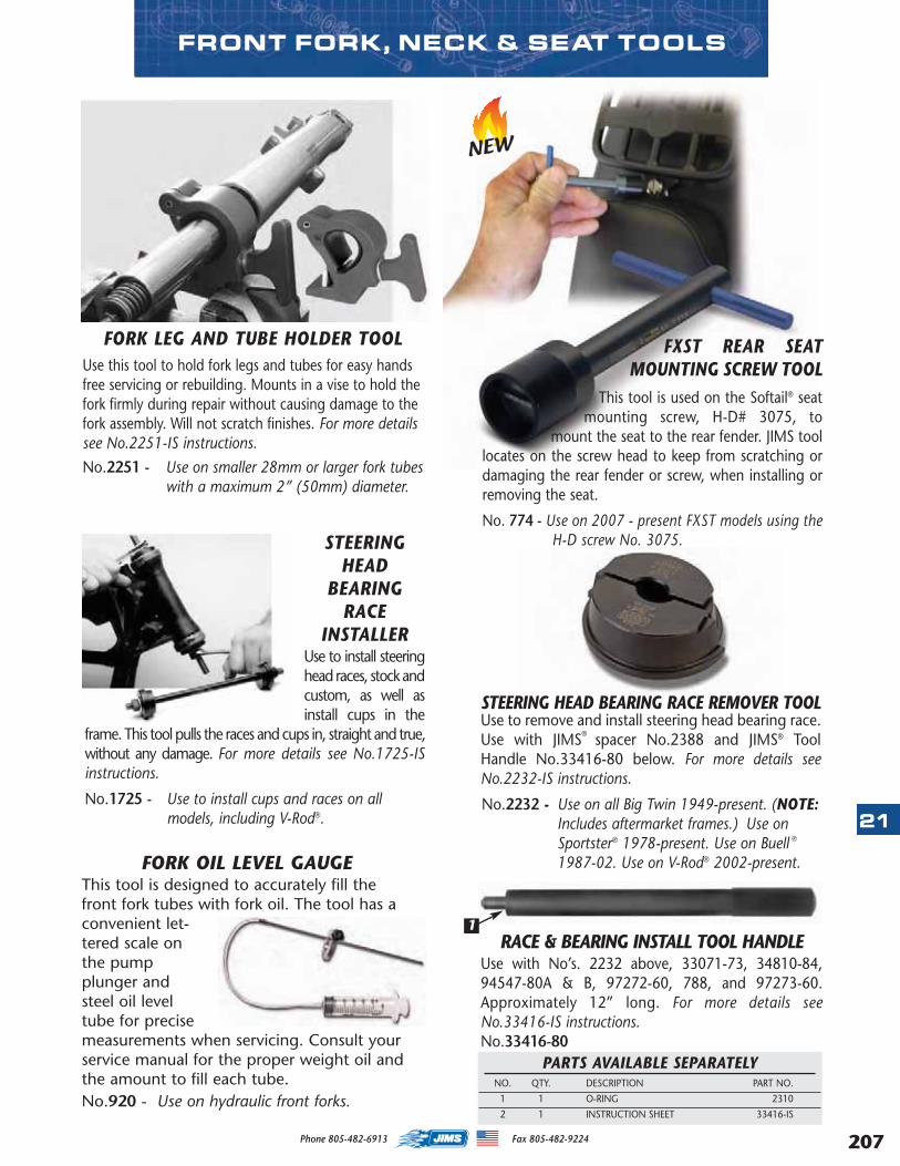
FORK LEG AND TUBE HOLDER TOOLUse this tool to hold fork legs and tubes for easy handsfree servicing or rebuilding. Mounts in a vise to hold thefork firmly during repair without causing damage to thefork assembly. Will not scratch finishes. For more detailssee No.2251-IS instructions.
No.2251 - Use on smaller 28mm or larger fork tubeswith a maximum 2” (50mm) diameter.
STEERINGHEAD
BEARINGRACE
INSTALLERUse to install steeringhead races, stock andcustom, as well asinstall cups in the
frame. This tool pulls the races and cups in, straight and true,without any damage. For more details see No.1725-ISinstructions.
No.1725 - Use to install cups and races on allmodels, including V-Rod®.
STEERING HEAD BEARING RACE REMOVER TOOLUse to remove and install steering head bearing race.Use with JIMS® spacer No.2388 and JIMS® ToolHandle No.33416-80 below. For more details seeNo.2232-IS instructions.
No.2232 -- Use on all Big Twin 1949-present. (NOTE:Includes aftermarket frames.) Use onSportster® 1978-present. Use on Buell ®
1987-02. Use on V-Rod® 2002-present.
RACE & BEARING INSTALL TOOL HANDLE Use with No’s. 2232 above, 33071-73, 34810-84,94547-80A & B, 97272-60, 788, and 97273-60.Approximately 12” long. For more details seeNo.33416-IS instructions.No.33416-80
1
PARTS AVAILABLE SEPARATELYNO. QTY. DESCRIPTION PART NO.
1 1 O-RING 2310
2 1 INSTRUCTION SHEET 33416-IS
FRONT FORK, NECK & SEAT TOOLS
FXST REAR SEATMOUNTING SCREW TOOL
This tool is used on the Softail® seatmounting screw, H-D# 3075, to
mount the seat to the rear fender. JIMS toollocates on the screw head to keep from scratching ordamaging the rear fender or screw, when installing orremoving the seat.
No. 774 - Use on 2007 - present FXST models using theH-D screw No. 3075.
NEW
FORK OIL LEVEL GAUGEThis tool is designed to accurately fill thefront fork tubes with fork oil. The tool has aconvenient let-tered scale onthe pumpplunger andsteel oil leveltube for precisemeasurements when servicing. Consult yourservice manual for the proper weight oil andthe amount to fill each tube.No.920 - Use on hydraulic front forks.
21
207Phone 805-482-6913 Fax 805-482-9224
MASTER 2013 CATALOG_JMS 2.qxp:Layout 1 8/2/12 8:31 PM Page 207
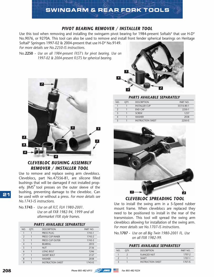
208
21
SWINGARM & REAR FORK TOOLS
PARTS AVAILABLE SEPARATELYNO. QTY. DESCRIPTION PART NO.
1 1 PRESS PLUG 1743-1
2 1 PRESS CUP INNER 1743-2
3 1 PRESS CUP OUTER 1743-3
4 1 BEARING 2010
5 1 NUT 2136
6 1 LONG BOLT 1246
7 1 SHORT BOLT 2137
8 1 WASHER 2038
9 1 INSTRUCTION SHEET 1743-IS
PIVOT BEARING REMOVER / INSTALLER TOOLUse this tool when removing and installing the swingarm pivot bearing for 1984-present Softails® that use H-D®
No.9076, or 9270A. This tool can also be used to remove and install front fender spherical bearings on HeritageSoftail® Springers 1997-02 & 2004-present that use H-D® No.9149.For more details see No.2250-IS instructions.
No.2250 - Use on all 1984-present FXST’s for pivot bearing. Use on1997-02 & 2004-present FLSTS for spherical bearing.
1 3
4
5
6
7
8
2
1 2
CLEVEBLOC SPREADING TOOLUse to install the swing arm in a 5-Speed rubbermount frame. When cleveblocs are replaced theyneed to be positioned to install in the rear of thetransmission. This tool will spread the swing armcleveblocs allowing for installation of the swing arm.For more details see No.1707-IS instructions.
No.1707 - Use on all Big Twin 1980-2001 FL. Use on all FXR 1982-99.
PARTS AVAILABLE SEPARATELYNO. QTY. DESCRIPTION PART NO.
1 1 INSTALLER CUP 35316-80-1
2 1 END CAP 2250-1
3 1 SCREW 1237
4 1 WASHER 2038
5 1 INSTRUCTION SHEET 2250-IS
PARTS AVAILABLE SEPARATELYNO. QTY. DESCRIPTION PART NO.
1 2 FLANGED NUT 1707-2
2 1 SHAFT 1707-1
3 1 INSTRUCTION SHEET 1707-IS
2
2
1
4
3
Phone 805-482-6913 Fax 805-482-9224
CLEVEBLOC BUSHING ASSEMBLYREMOVER / INSTALLER TOOL
Use to remove and replace swing arm cleveblocs.Cleveblocs, part No.47556-81, are silicone filledbushings that will be damaged if not installed prop-erly. JIMS® tool presses on the outer sleeve of thebushing, preventing damage to the clevebloc. Canbe used with or without a press. For more details seeNo.1743-IS instructions.
No.1743 - Use on all FLT, FLH 1980-2001.Use on all FXR 1982-94, 1999 and allaftermarket FXR style frames.
MASTER 2013 CATALOG_JMS 2.qxp:Layout 1 8/2/12 8:31 PM Page 208
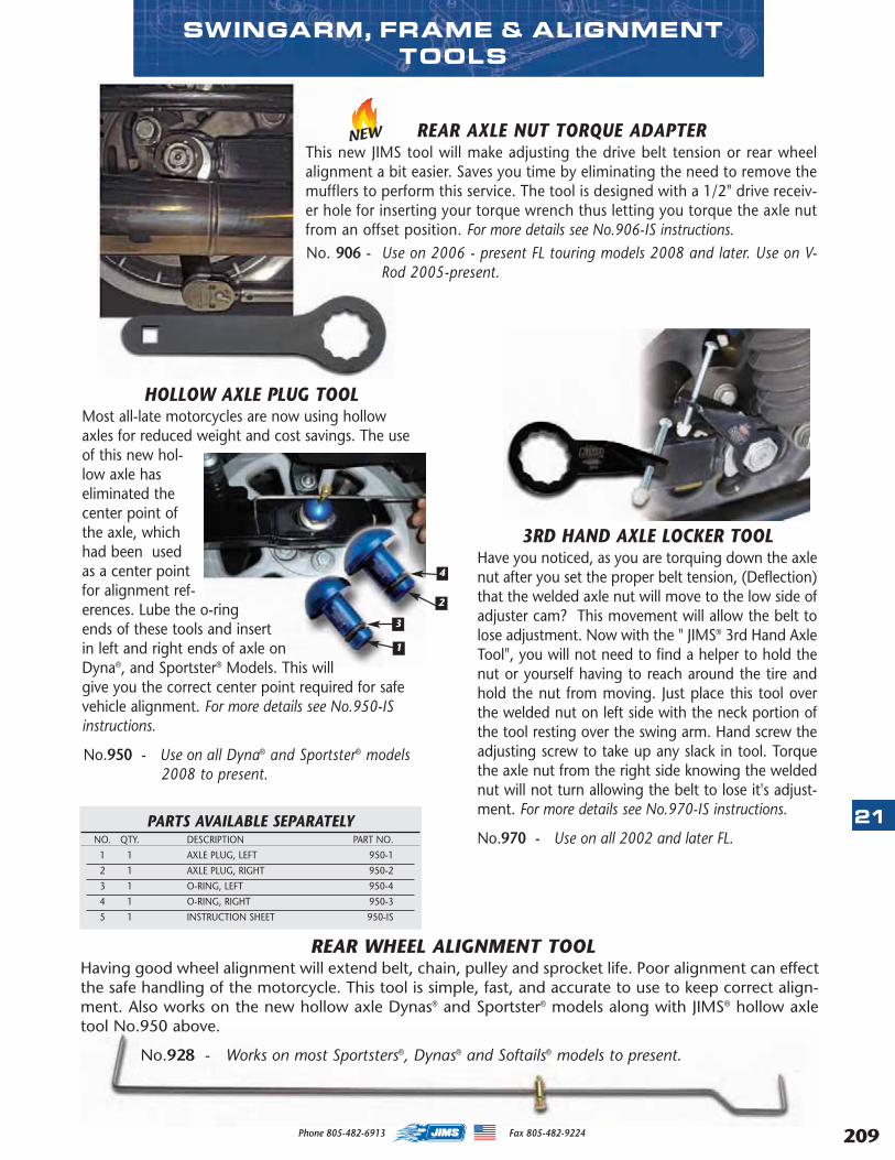
HOLLOW AXLE PLUG TOOLMost all-late motorcycles are now using hollowaxles for reduced weight and cost savings. The useof this new hol-low axle haseliminated thecenter point ofthe axle, whichhad been usedas a center pointfor alignment ref-erences. Lube the o-ringends of these tools and insertin left and right ends of axle onDyna®, and Sportster® Models. This willgive you the correct center point required for safevehicle alignment. For more details see No.950-ISinstructions.
No.950 - Use on all Dyna® and Sportster® models2008 to present.
SWINGARM, FRAME & ALIGNMENTTOOLS
PARTS AVAILABLE SEPARATELYNO. QTY. DESCRIPTION PART NO.
1 1 AXLE PLUG, LEFT 950-1
2 1 AXLE PLUG, RIGHT 950-2
3 1 O-RING, LEFT 950-4
4 1 O-RING, RIGHT 950-3
5 1 INSTRUCTION SHEET 950-IS
3RD HAND AXLE LOCKER TOOLHave you noticed, as you are torquing down the axlenut after you set the proper belt tension, (Deflection)that the welded axle nut will move to the low side ofadjuster cam? This movement will allow the belt tolose adjustment. Now with the " JIMS® 3rd Hand AxleTool", you will not need to find a helper to hold thenut or yourself having to reach around the tire andhold the nut from moving. Just place this tool overthe welded nut on left side with the neck portion ofthe tool resting over the swing arm. Hand screw theadjusting screw to take up any slack in tool. Torquethe axle nut from the right side knowing the weldednut will not turn allowing the belt to lose it's adjust-ment. For more details see No.970-IS instructions.
No.970 - Use on all 2002 and later FL.
1
2
3
4
REAR WHEEL ALIGNMENT TOOLHaving good wheel alignment will extend belt, chain, pulley and sprocket life. Poor alignment can effectthe safe handling of the motorcycle. This tool is simple, fast, and accurate to use to keep correct align-ment. Also works on the new hollow axle Dynas® and Sportster® models along with JIMS® hollow axletool No.950 above.
No.928 - Works on most Sportsters®, Dynas® and Softails® models to present.
REAR AXLE NUT TORQUE ADAPTERThis new JIMS tool will make adjusting the drive belt tension or rear wheelalignment a bit easier. Saves you time by eliminating the need to remove themufflers to perform this service. The tool is designed with a 1/2" drive receiv-er hole for inserting your torque wrench thus letting you torque the axle nutfrom an offset position. For more details see No.906-IS instructions.No. 906 - Use on 2006 - present FL touring models 2008 and later. Use on V-
Rod 2005-present.
NEW
21
209Phone 805-482-6913 Fax 805-482-9224
MASTER 2013 CATALOG_JMS 2.qxp:Layout 1 8/2/12 8:31 PM Page 209
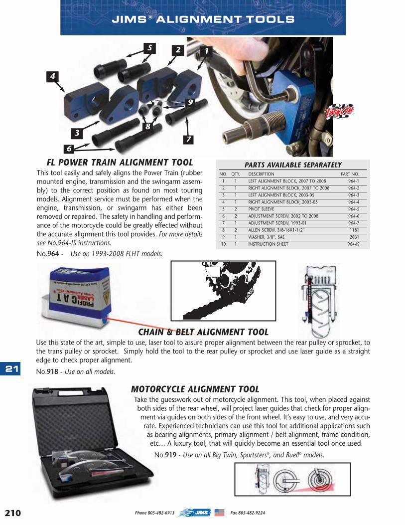
210
21
Phone 805-482-6913 Fax 805-482-9224
JIMS ® ALIGNMENT TOOLS
MOTORCYCLE ALIGNMENT TOOLTake the guesswork out of motorcycle alignment. This tool, when placed againstboth sides of the rear wheel, will project laser guides that check for proper align-ment via guides on both sides of the front wheel. It’s easy to use, and very accu-rate. Experienced technicians can use this tool for additional applications suchas bearing alignments, primary alignment / belt alignment, frame condition,etc… A luxury tool, that will quickly become an essential tool once used.
No.919 - Use on all Big Twin, Sportsters®, and Buell® models.
CHAIN & BELT ALIGNMENT TOOLUse this state of the art, simple to use, laser tool to assure proper alignment between the rear pulley or sprocket, tothe trans pulley or sprocket. Simply hold the tool to the rear pulley or sprocket and use laser guide as a straightedge to check proper alignment.
No.918 - Use on all models.
FL POWER TRAIN ALIGNMENT TOOLThis tool easily and safely aligns the Power Train (rubbermounted engine, transmission and the swingarm assem-bly) to the correct position as found on most touringmodels. Alignment service must be performed when theengine, transmission, or swingarm has either beenremoved or repaired. The safety in handling and perform-ance of the motorcycle could be greatly effected withoutthe accurate alignment this tool provides. For more detailssee No.964-IS instructions.
No.964 - Use on 1993-2008 FLHT models.
73
6
8
9
4
125
PARTS AVAILABLE SEPARATELYNO. QTY. DESCRIPTION PART NO.
1 1 LEFT ALIGNMENT BLOCK, 2007 TO 2008 964-1
2 1 RIGHT ALIGNMENT BLOCK, 2007 TO 2008 964-2
3 1 LEFT ALIGNMENT BLOCK, 2003-05 964-3
4 1 RIGHT ALIGNMENT BLOCK, 2003-05 964-4
5 2 PIVOT SLEEVE 964-5
6 2 ADJUSTMENT SCREW, 2002 TO 2008 964-6
7 1 ADJUSTMENT SCREW, 1993-01 964-7
8 2 ALLEN SCREW, 3/8-16X1-1/2” 1181
9 1 WASHER, 3/8”, SAE 2031
10 1 INSTRUCTION SHEET 964-IS
MASTER 2013 CATALOG_JMS 2.qxp:Layout 1 8/2/12 8:31 PM Page 210

211
22
Phone 805-482-6913 Fax 805-482-9224
CHAIN & BELT DRIVE TOOLS
MASTER LINK PLIERSDesigned to simplify installation and removal ofclip-type master links. One tip is shorter andnotched to be placed on the pin which allowsthe longer tip to push the clip.
No.921 - Master Link Pliers.
BELT TENSION GAUGEThis compact designed tool isused to assist in properlyadjusting secondary belt ten-sion with a 10 lb.. specification.Tool has an easy to read scale.Use on all rear belt drivenO.E.M. or aftermarket motorcy-cles.
No.923 - Used on all rear beltdriven O.E.M. or after-market motorcycles.
REPLACEMENTPRESS PLATES ONLYNo.924 - Used on tool
No.925 above.
JUMBO CHAIN TOOLThis tool is de-signed to breakroller chains up to#630 and fits allstandard & O-ringchain sizes #520 to#630. Its designedto rivet chains up to#530. (not #630)Master link sideplate press kitincluded to press onside plates on chainsup to #530. (not#630) The screwsand attachments areheat treated for strength and durability. Theextractor pin is precisely guided by a removableguide ensuring long pin life. This may be boltedto a work bench, supported in a vise, or held byhandle. When bolted to a solid surface, air orelectric wrenches may be used to break chain.This tool is recommended for heavy duty use.Instructions included with tool.
No.926 - See above chain application info above forchain type and sizes.
CHAIN PRESS TOOL KITSince about1990, most newchains use press-fit type sideplates on thec o n n e c t i n glinks. With thistype of link theside plate can-not be installedproperly with-out the aid ofthis special tool. The chain manufacturers havedetermined a press fit adds strength to the con-necting link and should always be used.
No. 925 - Used on #520 - # 530 chain with press fitconnecting links either standard or o-ringstyle.
MASTER 2013 CATALOG_JMS 2.qxp:Layout 1 8/2/12 8:31 PM Page 211
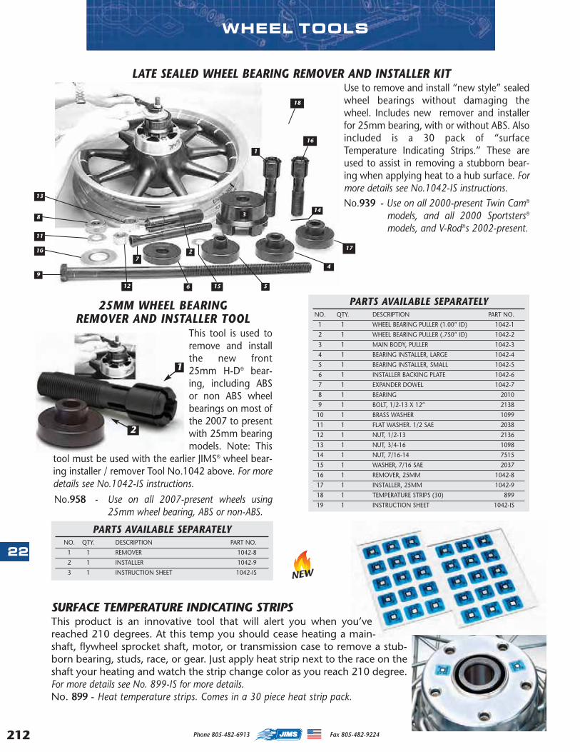
212
22
Phone 805-482-6913 Fax 805-482-9224
LATE SEALED WHEEL BEARING REMOVER AND INSTALLER KITUse to remove and install “new style” sealedwheel bearings without damaging thewheel. Includes new remover and installerfor 25mm bearing, with or without ABS. Alsoincluded is a 30 pack of “surfaceTemperature Indicating Strips.” These areused to assist in removing a stubborn bear-ing when applying heat to a hub surface. Formore details see No.1042-IS instructions.No.939 - Use on all 2000-present Twin Cam®
models, and all 2000 Sportsters®
models, and V-Rod®s 2002-present.
PARTS AVAILABLE SEPARATELYNO. QTY. DESCRIPTION PART NO.
1 1 WHEEL BEARING PULLER (1.00” ID) 1042-1
2 1 WHEEL BEARING PULLER (.750” ID) 1042-2
3 1 MAIN BODY, PULLER 1042-3
4 1 BEARING INSTALLER, LARGE 1042-4
5 1 BEARING INSTALLER, SMALL 1042-5
6 1 INSTALLER BACKING PLATE 1042-6
7 1 EXPANDER DOWEL 1042-7
8 1 BEARING 2010
9 1 BOLT, 1/2-13 X 12” 2138
10 1 BRASS WASHER 1099
11 1 FLAT WASHER. 1/2 SAE 2038
12 1 NUT, 1/2-13 2136
13 1 NUT, 3/4-16 1098
14 1 NUT, 7/16-14 7515
15 1 WASHER, 7/16 SAE 2037
16 1 REMOVER, 25MM 1042-8
17 1 INSTALLER, 25MM 1042-9
18 1 TEMPERATURE STRIPS (30) 899
19 1 INSTRUCTION SHEET 1042-IS
25MM WHEEL BEARINGREMOVER AND INSTALLER TOOL
This tool is used toremove and installthe new front25mm H-D® bear-ing, including ABSor non ABS wheelbearings on most ofthe 2007 to presentwith 25mm bearingmodels. Note: This
tool must be used with the earlier JIMS® wheel bear-ing installer / remover Tool No.1042 above. For moredetails see No.1042-IS instructions.
No.958 - Use on all 2007-present wheels using25mm wheel bearing, ABS or non-ABS.
WHEEL TOOLS
1
2
SURFACE TEMPERATURE INDICATING STRIPSThis product is an innovative tool that will alert you when you’vereached 210 degrees. At this temp you should cease heating a main-shaft, flywheel sprocket shaft, motor, or transmission case to remove a stub-born bearing, studs, race, or gear. Just apply heat strip next to the race on theshaft your heating and watch the strip change color as you reach 210 degree.For more details see No. 899-IS for more details. No. 899 - Heat temperature strips. Comes in a 30 piece heat strip pack.
PARTS AVAILABLE SEPARATELYNO. QTY. DESCRIPTION PART NO.
1 1 REMOVER 1042-8
2 1 INSTALLER 1042-9
3 1 INSTRUCTION SHEET 1042-IS
27
6 5
9
11
12 15
10
1
4
8
13
16
17
18
143
NEW
MASTER 2013 CATALOG_JMS 2.qxp:Layout 1 8/2/12 8:31 PM Page 212
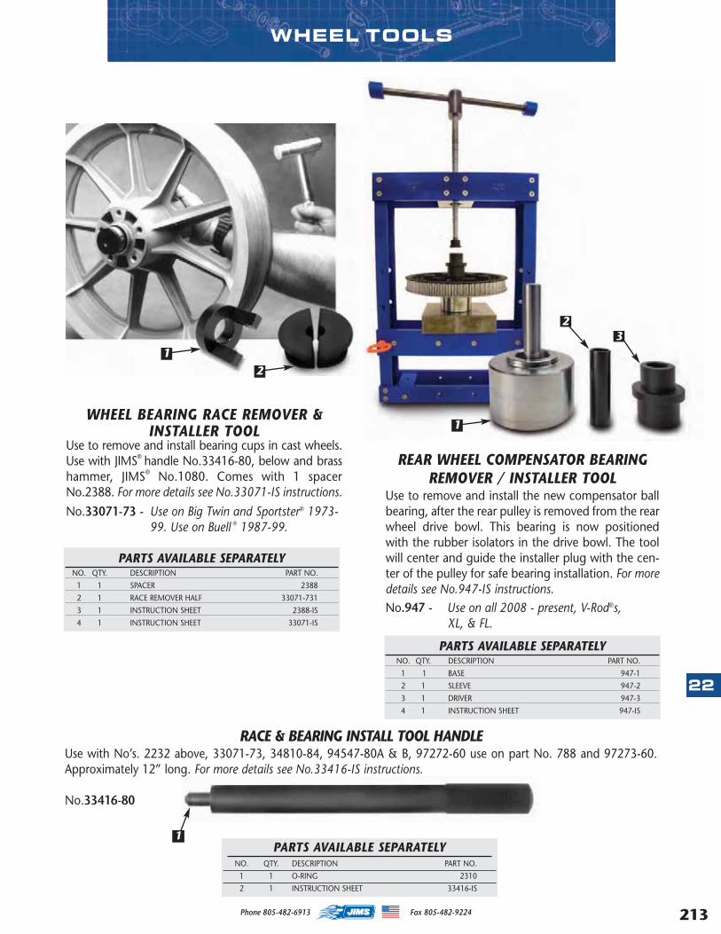
22
213Phone 805-482-6913 Fax 805-482-9224
WHEEL BEARING RACE REMOVER &INSTALLER TOOL
Use to remove and install bearing cups in cast wheels.Use with JIMS® handle No.33416-80, below and brasshammer, JIMS® No.1080. Comes with 1 spacerNo.2388. For more details see No.33071-IS instructions.
No.33071-73 - Use on Big Twin and Sportster® 1973-99. Use on Buell ® 1987-99.
REAR WHEEL COMPENSATOR BEARINGREMOVER / INSTALLER TOOL
Use to remove and install the new compensator ballbearing, after the rear pulley is removed from the rearwheel drive bowl. This bearing is now positionedwith the rubber isolators in the drive bowl. The toolwill center and guide the installer plug with the cen-ter of the pulley for safe bearing installation. For moredetails see No.947-IS instructions.No.947 - Use on all 2008 - present, V-Rod®s,
XL, & FL.
PARTS AVAILABLE SEPARATELYNO. QTY. DESCRIPTION PART NO.
1 1 BASE 947-1
2 1 SLEEVE 947-2
3 1 DRIVER 947-3
4 1 INSTRUCTION SHEET 947-IS
1
23
RACE & BEARING INSTALL TOOL HANDLE Use with No’s. 2232 above, 33071-73, 34810-84, 94547-80A & B, 97272-60 use on part No. 788 and 97273-60.Approximately 12” long. For more details see No.33416-IS instructions.
No.33416-80
1PARTS AVAILABLE SEPARATELY
NO. QTY. DESCRIPTION PART NO.
1 1 O-RING 2310
2 1 INSTRUCTION SHEET 33416-IS
WHEEL TOOLS
PARTS AVAILABLE SEPARATELYNO. QTY. DESCRIPTION PART NO.
1 1 SPACER 2388
2 1 RACE REMOVER HALF 33071-731
3 1 INSTRUCTION SHEET 2388-IS
4 1 INSTRUCTION SHEET 33071-IS
1
2
MASTER 2013 CATALOG_JMS 2.qxp:Layout 1 8/2/12 8:31 PM Page 213
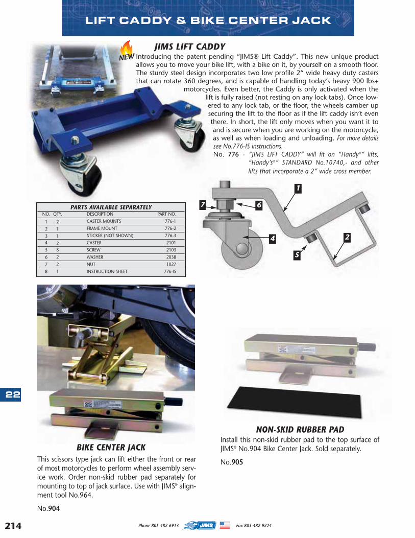
214
22
This scissors type jack can lift either the front or rearof most motorcycles to perform wheel assembly serv-ice work. Order non-skid rubber pad separately formounting to top of jack surface. Use with JIMS® align-ment tool No.964.
No.904
NON-SKID RUBBER PADInstall this non-skid rubber pad to the top surface ofJIMS® No.904 Bike Center Jack. Sold separately.
No.905
BIKE CENTER JACK
LIFT CADDY & BIKE CENTER JACK
JIMS LIFT CADDYIntroducing the patent pending “JIMS® Lift Caddy”. This new unique productallows you to move your bike lift, with a bike on it, by yourself on a smooth floor.The sturdy steel design incorporates two low profile 2“ wide heavy duty castersthat can rotate 360 degrees, and is capable of handling today’s heavy 900 lbs+
motorcycles. Even better, the Caddy is only activated when thelift is fully raised (not resting on any lock tabs). Once low-ered to any lock tab, or the floor, the wheels camber upsecuring the lift to the floor as if the lift caddy isn’t eventhere. In short, the lift only moves when you want it toand is secure when you are working on the motorcycle,as well as when loading and unloading. For more detailssee No.776-IS instructions. No. 776 - “JIMS LIFT CADDY” will fit on “Handy®” lifts,
“Handy’s®” STANDARD No.10740,- and otherlifts that incorporate a 2” wide cross member.
1
2
5
4
7 6PARTS AVAILABLE SEPARATELYNO. QTY. DESCRIPTION PART NO.
1 2 CASTER MOUNTS 776-1
2 1 FRAME MOUNT 776-2
3 1 STICKER (NOT SHOWN) 776-3
4 2 CASTER 2101
5 8 SCREW 2103
6 2 WASHER 2038
7 2 NUT 1027
8 1 INSTRUCTION SHEET 776-IS
NEW
Phone 805-482-6913 Fax 805-482-9224
MASTER 2013 CATALOG_JMS 2.qxp:Layout 1 8/2/12 8:31 PM Page 214
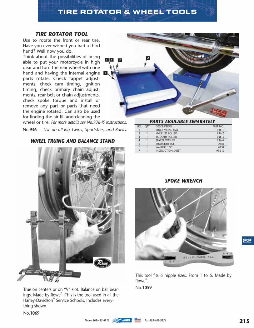
TIRE ROTATOR TOOLUse to rotate the front or rear tire.Have you ever wished you had a thirdhand? Well now you do.Think about the possibilities of beingable to put your motorcycle in highgear and turn the rear wheel with onehand and having the internal engineparts rotate. Check tappet adjust-ments, check cam timing, ignitiontiming, check primary chain adjust-ments, rear belt or chain adjustments,check spoke torque and install orremove any part or parts that needthe engine rotated. Can also be usedfor finding the air fill and cleaning thewheel or tire. For more details see No.936-IS instructions.
No.936 - Use on all Big Twins, Sportsters, and Buells.
PARTS AVAILABLE SEPARATELYNO. QTY DESCRIPTION PART NO.
1 1 SHEET METAL BASE 936-1 2 1 KNURLED ROLLER 936-2 3 1 SMOOTH ROLLER 936-3 4 1 SPACER WASHER 936-45 1 SHOULDER BOLT 20386 1 WASHER, 1/2” 20387 1 INSTRUCTION SHEET 936-IS
3
WHEEL TRUING AND BALANCE STAND
True on centers or on “V” slot. Balance on ball bear-ings. Made by Rowe®. This is the tool used in all theHarley-Davidson® Service Schools. Includes every-thing shown.
No.1069
SPOKE WRENCH
This tool fits 6 nipple sizes. From 1 to 6. Made byRowe®.
No.1059
1
5 6 42
TIRE ROTATOR & WHEEL TOOLS
22
215Phone 805-482-6913 Fax 805-482-9224
MASTER 2013 CATALOG_JMS 2.qxp:Layout 1 8/2/12 8:31 PM Page 215
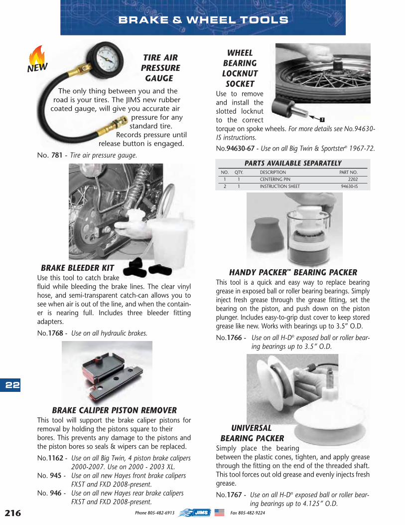
216
22
TIRE AIRPRESSUREGAUGE
The only thing between you and theroad is your tires. The JIMS new rubber
coated gauge, will give you accurate airpressure for anystandard tire.
Records pressure untilrelease button is engaged.
No. 781 - Tire air pressure gauge.
BRAKE & WHEEL TOOLS
BRAKE CALIPER PISTON REMOVERThis tool will support the brake caliper pistons forremoval by holding the pistons square to their bores. This prevents any damage to the pistons andthe piston bores so seals & wipers can be replaced.
No.1162 - Use on all Big Twin, 4 piston brake calipers2000-2007. Use on 2000 - 2003 XL.
No. 945 - Use on all new Hayes front brake calipersFXST and FXD 2008-present.
No. 946 - Use on all new Hayes rear brake calipersFXST and FXD 2008-present.
BRAKE BLEEDER KITUse this tool to catch brakefluid while bleeding the brake lines. The clear vinylhose, and semi-transparent catch-can allows you tosee when air is out of the line, and when the contain-er is nearing full. Includes three bleeder fittingadapters.
No.1768 - Use on all hydraulic brakes.
HANDY PACKER™ BEARING PACKERThis tool is a quick and easy way to replace bearinggrease in exposed ball or roller bearing bearings. Simplyinject fresh grease through the grease fitting, set thebearing on the piston, and push down on the pistonplunger. Includes easy-to-grip dust cover to keep storedgrease like new. Works with bearings up to 3.5” O.D.
No.1766 - Use on all H-D® exposed ball or roller bear-ing bearings up to 3.5” O.D.
UNIVERSALBEARING PACKER
Simply place the bearingbetween the plastic cones, tighten, and apply greasethrough the fitting on the end of the threaded shaft.This tool forces out old grease and evenly injects freshgrease.
No.1767 - Use on all H-D® exposed ball or roller bear-ing bearings up to 4.125” O.D.
WHEELBEARINGLOCKNUTSOCKET
Use to removeand install theslotted locknutto the correcttorque on spoke wheels. For more details see No.94630-IS instructions.
No.94630-67 - Use on all Big Twin & Sportster® 1967-72.
PARTS AVAILABLE SEPARATELYNO. QTY. DESCRIPTION PART NO.
1 1 CENTERING PIN 2202
2 1 INSTRUCTION SHEET 94630-IS
1
NEW
Phone 805-482-6913 Fax 805-482-9224
MASTER 2013 CATALOG_JMS 2.qxp:Layout 1 8/2/12 8:31 PM Page 216
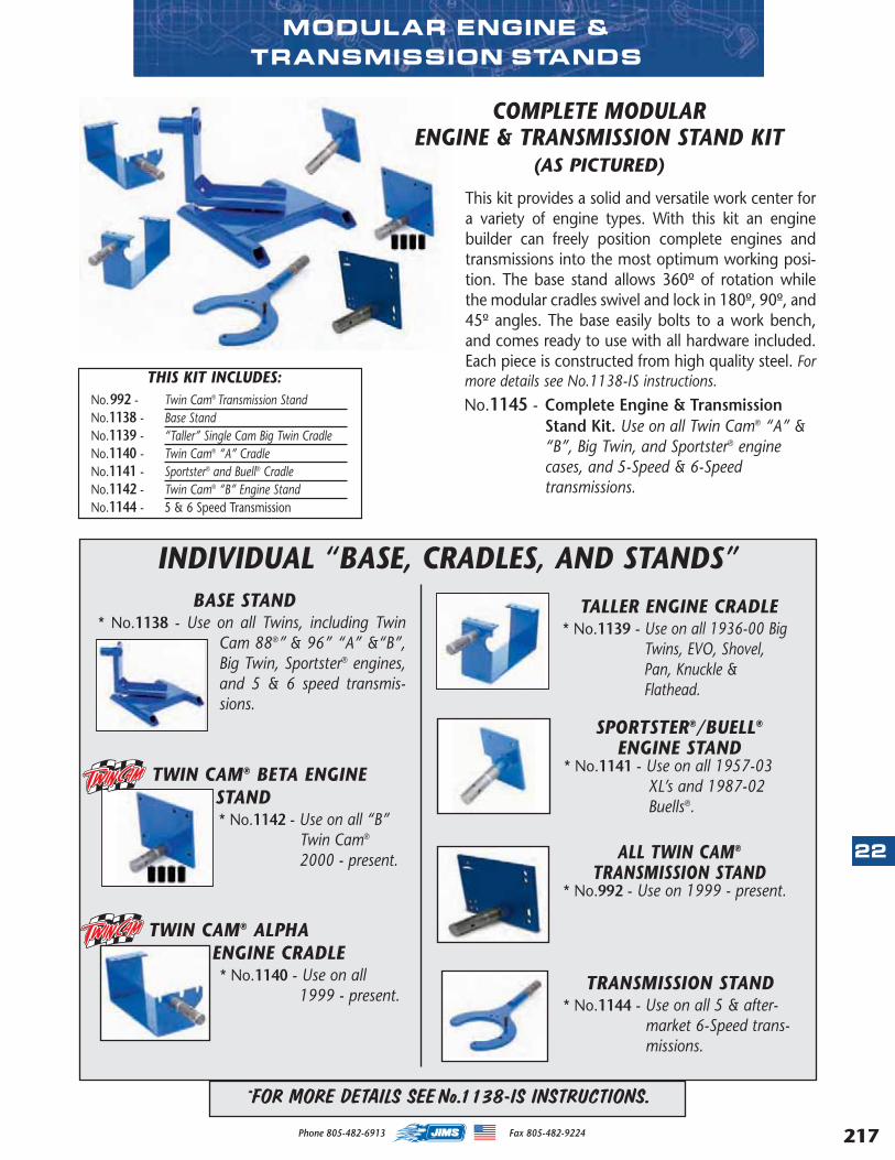
MODULAR ENGINE & TRANSMISSION STANDS
SPORTSTER®/BUELL®
ENGINE STAND* No.1141 - Use on all 1957-03
XL’s and 1987-02Buells®.
ALL TWIN CAM®
TRANSMISSION STAND* No.992 - Use on 1999 - present.
This kit provides a solid and versatile work center fora variety of engine types. With this kit an enginebuilder can freely position complete engines andtransmissions into the most optimum working posi-tion. The base stand allows 360º of rotation whilethe modular cradles swivel and lock in 180º, 90º, and45º angles. The base easily bolts to a work bench,and comes ready to use with all hardware included.Each piece is constructed from high quality steel. Formore details see No.1138-IS instructions.
No.1145 - Complete Engine & TransmissionStand Kit. Use on all Twin Cam® “A” &“B”, Big Twin, and Sportster® enginecases, and 5-Speed & 6-Speedtransmissions.
BASE STAND* No.1138 - Use on all Twins, including Twin
Cam 88®” & 96” “A” &“B”,Big Twin, Sportster® engines,and 5 & 6 speed transmis-sions.
TWIN CAM® BETA ENGINESTAND* No.1142 - Use on all “B”
Twin Cam®
2000 - present.
TWIN CAM® ALPHA ENGINE CRADLE* No.1140 - Use on all
1999 - present.
INDIVIDUAL “BASE, CRADLES, AND STANDS”TALLER ENGINE CRADLE
* No.1139 - Use on all 1936-00 BigTwins, EVO, Shovel,Pan, Knuckle &Flathead.
TRANSMISSION STAND* No.1144 - Use on all 5 & after-
market 6-Speed trans-missions.
THIS KIT INCLUDES:No.992 - Twin Cam® Transmission StandNo.1138 - Base Stand No.1139 - “Taller” Single Cam Big Twin CradleNo.1140 - Twin Cam® “A” CradleNo.1141 - Sportster® and Buell® CradleNo.1142 - Twin Cam® “B” Engine StandNo.1144 - 5 & 6 Speed Transmission
COMPLETE MODULAR ENGINE & TRANSMISSION STAND KIT
(AS PICTURED)
*FOR MORE DETAILS SEE No.1138-IS INSTRUCTIONS.
22
217Phone 805-482-6913 Fax 805-482-9224
MASTER 2013 CATALOG_JMS 2.qxp:Layout 1 8/2/12 8:31 PM Page 217
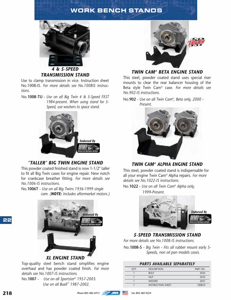
218
22
TWIN CAM® BETA ENGINE STANDThis steel, powder coated stand uses special risermounts to clear the rear balancer housing of theBeta style Twin Cam® case. For more details seeNo.902-IS instructions.
No.902 - Use on all Twin Cam®, Beta only, 2000 - Present.
5-SPEED TRANSMISSION STANDFor more details see No.1008-IS instructions.
No.1008-5 - Big Twin - Fits all rubber mount early 5-Speeds, non oil pan models cases.
PARTS AVAILABLE SEPARATELYQTY. DESCRIPTION PART NO.
1 BOLT 2034
1 NUT 2035
1 WASHER 2031
1 INSTRUCTION SHEET 1008-IS
XL ENGINE STANDTop-quality steel bench stand simplifies engineoverhaul and has powder coated finish. For moredetails see No.1007-IS instructions.No.1007 - Use on all Sportster® 1957-2003.
Use on all Buell ® 1987-2002.
Endorsed By
TWIN CAM® ALPHA ENGINE STANDThis steel, powder coated stand is indispensable forall your engine Twin Cam® Alpha repairs. For moredetails see No.1022-IS instructions.No.1022 - Use on all Twin Cam® Alpha only,
1999-Present.
WORK BENCH STANDS
Endorsed By
Endorsed By
4 & 5-SPEEDTRANSMISSION STAND
Use to clamp transmission in vice. Instruction sheetNo.1008-IS. For more details see No.1008IS instruc-tions.
No.1008-TU - Use on all Big Twin 4 & 5-Speed FXST1984-present. When using stand for 5-Speed, use washers to space stand.
"TALLER" BIG TWIN ENGINE STANDThis powder coated finished stand is now 1-1/2" tallerto fit all Big Twin cases for engine repair. New notchfor crankcase breather fitting. For more details seeNo.1006-IS instructions.No.1006T - Use on all Big Twins 1936-1999 single
cam. (NOTE: Includes aftermarket motors.)
Phone 805-482-6913 Fax 805-482-9224
MASTER 2013 CATALOG_JMS 2.qxp:Layout 1 8/2/12 8:31 PM Page 218
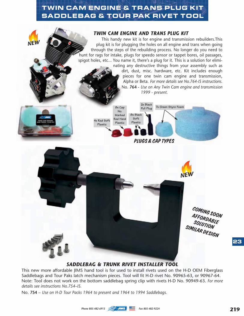
TWIN CAM ENGINE & TRANS PLUG KITSADDLEBAG & TOUR PAK RIVET TOOL
TWIN CAM ENGINE AND TRANS PLUG KITThis handy new kit is for engine and transmission rebuilders.This
plug kit is for plugging the holes on all engine and trans when goingthrough the steps of the rebuilding process. No longer do you need to
hunt for rags for intake, plugs for speedo sensor or tappet bores, oil passages,spigot holes, etc... You name it, there’s a plug for it. This is a solution for elimi-
nating any destructive things from your assembly such asdirt, dust, misc. hardware, etc. Kit includes enoughpieces for one twin cam engine and transmission,Alpha or Beta. For more details see No.764-IS instructions.
No. 764 - Use on Any Twin Cam engine and transmission1999 - present.
PLUGS & CAP TYPES
7x Green Styro Foam
8x BlackSoft
Plastic
2x BlackPull Plug8x Cap
No.Marked
Red HardPlastic
4x Red SoftPlastic
NEW
SADDLEBAG & TRUNK RIVET INSTALLER TOOLThis new more affordable JIMS hand tool is for used to install rivets used on the H-D OEM FiberglassSaddlebags and Tour Paks latch mechanism pieces. Tool will fit H-D rivet No. 90965-63, or 90967-64.Note: Tool does not work on the bottom saddlebag spring clip with rivets H-D No. 90949-63. For moredetails see instructions No.754–IS.No. 754 – Use on H-D Tour Packs 1964 to present and 1964 to 1994 Saddlebags.
23
219Phone 805-482-6913 Fax 805-482-9224
NEW
COMING SOONAFFORDABLESOLUTION SIMILAR DESIGN
MASTER 2013 CATALOG_JMS 2.qxp:Layout 1 8/2/12 8:31 PM Page 219
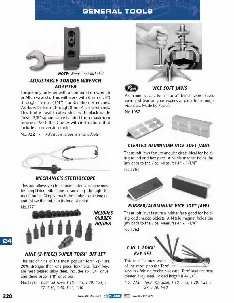
220
247-IN-1 TORX®
KEY SETThis tool features sevenof the most popular Torx®
keys in a folding pocket size case. Torx® keys are heattreated alloy steel. Folded length is 4-1/4”.
No.1772 - Torx® Key Sizes: T-10, T-15, T-20, T-25, T-27, T-30, T-40
NINE (2-PIECE) SUPER TORX® BIT SETThis set of nine of the most popular Torx® keys are20% stronger than one piece Torx® bits. Torx® keysare heat treated alloy steel. Includes six 1/4” drive,and three larger 3/8” drive bits.
No.1773 - Torx® Bit Sizes: T-10, T-15, T-20, T-25, T-27, T-30, T-40, T-45, T-50
RUBBER/ALUMINUM VICE SOFT JAWSThese soft jaws feature a rubber face good for hold-ing odd shaped objects. A Nitrile magnet holds thejaw pads to the vice. Measures 4” x 1-1/4”
No.1762
VICE SOFT JAWSAluminum covers for 3” to 5” bench vices. Saveswear and tear on your expensive parts from roughvice jaws. Made by Rowe®.
No.1057
INCLUDESRUBBERHOLDER
CLEATED ALUMINUM VICE SOFT JAWSThese soft jaws feature angular cleats ideal for hold-ing round and hex parts. A Nitrile magnet holds thejaw pads to the vice. Measures 4” x 1-1/4”
No.1761
MECHANIC’S STETHOSCOPEThis tool allows you to pinpoint internal engine noiseby amplifying vibrations resonating through themetal probe. Simply touch the probe to the engine,and follow the noise to its loudest point.
No.1771
ADJUSTABLE TORQUE WRENCHADAPTER
Torque any fastener with a combination wrenchor Allen wrench. This will work with 6mm (1/4")through 19mm (3/4") combination wrenches.Works with 6mm through 8mm Allen wrenches.This tool is heat-treated steel with black oxidefinish. 3/8" square drive is rated for a maximumtorque of 90 ft-lbs. Comes with instructions thatinclude a conversion table.
No.922 - Adjustable torque wrench adapter.
NOTE: Wrench not included.
GENERAL TOOLS
Phone 805-482-6913 Fax 805-482-9224
MASTER 2013 CATALOG_JMS 2.qxp:Layout 1 8/2/12 8:31 PM Page 220
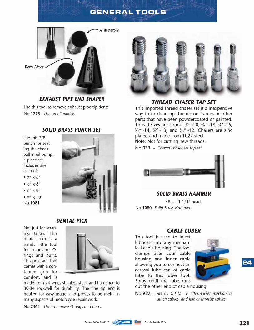
GENERAL TOOLS
EXHAUST PIPE END SHAPERUse this tool to remove exhaust pipe tip dents.
No.1775 - Use on all models.
Dent Before
Dent After
SOLID BRASS HAMMER48oz. 1-1/4” head.
No.1080- Solid Brass Hammer.
DENTAL PICKNot just for scrap-ing tartar. Thisdental pick is ahandy little toolfor removing O-rings and burrs.This precision toolcomes with a con-toured grip forcomfort, and ismade from 24 series stainless steel, and hardened to30-34 rockwell for durability. The fine tip end ishooked for easy usage, and proves to be useful inmany aspects of motorcycle repair work.
No.2361 - Use to remove O-rings and burrs.
SOLID BRASS PUNCH SETUse this 3/8”punch for seat-ing the checkball in oil pump.4 piece setincludes oneeach of:• 3⁄8” x 6”• 1⁄2” x 8”• 5⁄8” x 9”• 3⁄4” x 10”No.1081
THREAD CHASER TAP SETThis imported thread chaser set is a inexpensiveway to to clean up threads on frames or otherparts that have been powdercoated or painted.Thread sizes are course, 1⁄4” -20, 5⁄16” -18, 3⁄8” -16,7⁄16” -14, 1⁄2” -13, and 9⁄16” -12. Chasers are zincplated and made from 1027 steel. Note: Not for cutting new threads. No.933 - Thread chaser set tap set.
CABLE LUBERThis tool is used to injectlubricant into any mechan-ical cable housing. The toolclamps over your cablehousing and inner cableallowing you to connect anaerosol lube can of cablelube to this luber tool.Spray until the lube runsout the other end of cable housing.
No.927 - Fits all O.E.M. or aftermarket mechanicalclutch cables, and idle or throttle cables.
24
221Phone 805-482-6913 Fax 805-482-9224
MASTER 2013 CATALOG_JMS 2.qxp:Layout 1 8/2/12 8:31 PM Page 221
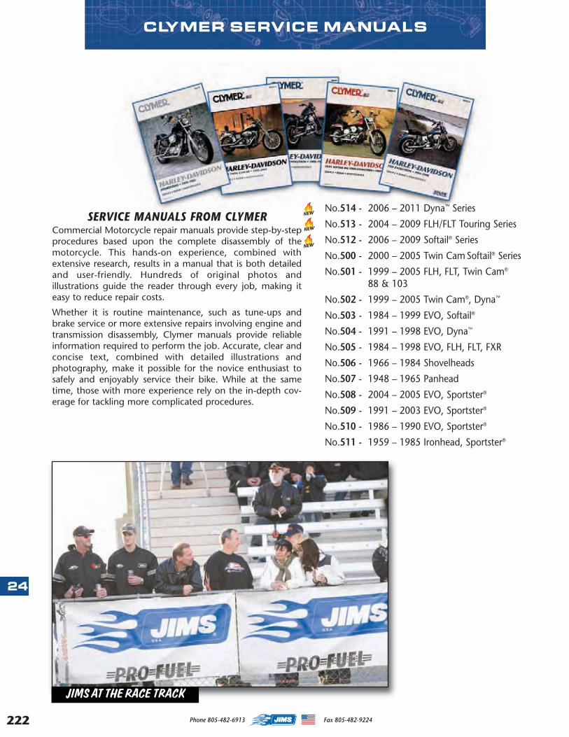
222
24
SERVICE MANUALS FROM CLYMERCommercial Motorcycle repair manuals provide step-by-stepprocedures based upon the complete disassembly of themotorcycle. This hands-on experience, combined withextensive research, results in a manual that is both detailedand user-friendly. Hundreds of original photos andillustrations guide the reader through every job, making iteasy to reduce repair costs.
Whether it is routine maintenance, such as tune-ups andbrake service or more extensive repairs involving engine andtransmission disassembly, Clymer manuals provide reliableinformation required to perform the job. Accurate, clear andconcise text, combined with detailed illustrations andphotography, make it possible for the novice enthusiast tosafely and enjoyably service their bike. While at the sametime, those with more experience rely on the in-depth cov-erage for tackling more complicated procedures.
NEW
No.514 - 2006 – 2011 Dyna™ Series
No.513 - 2004 – 2009 FLH/FLT Touring Series
No.512 - 2006 – 2009 Softail® Series
No.500 - 2000 – 2005 Twin Cam Softail® Series
No.501 - 1999 – 2005 FLH, FLT, Twin Cam®
88 & 103
No.502 - 1999 – 2005 Twin Cam®, Dyna™
No.503 - 1984 – 1999 EVO, Softail®
No.504 - 1991 – 1998 EVO, Dyna™
No.505 - 1984 – 1998 EVO, FLH, FLT, FXR
No.506 - 1966 – 1984 Shovelheads
No.507 - 1948 – 1965 Panhead
No.508 - 2004 – 2005 EVO, Sportster®
No.509 - 1991 – 2003 EVO, Sportster®
No.510 - 1986 – 1990 EVO, Sportster®
No.511 - 1959 – 1985 Ironhead, Sportster®
NEW
CLYMER SERVICE MANUALS
NEW
Phone 805-482-6913 Fax 805-482-9224
JIMS AT THE RACE TRACK
MASTER 2013 CATALOG_JMS 2.qxp:Layout 1 8/2/12 8:31 PM Page 222

CHEMICALS, LUBRICANTS & SUPPLYS
PERMATEX MEDIUM OR HIGH STRENGTH GEL TWIST OR BOTTLE THREADLOCKER
Medium Strength Blue is a OEM specified all purposethreadlocker. Ideal for all nuts and bolts applications.Locks and seals while preventing parts loosening dueto vibration. High Strength Red is a OEM specifiedand perfect for permanently locking cylinder studs,motor mount hardware, etc. Adds 3,000 PSI holdingpower on slip fit assemblies. Gel Twist Applicator:Medium Strength Blue Gel and High Strength RedGel twist pin-point applicator puts the threadlockerwhere you want it on the part. This threadlocker gelprovides the liquid quality without the problems. Nodrips, No globs, No waste.
No.4501 - 10g Medium Strength Blue Gel thread-locker twist applicator.
No.4502 - 10g High Strength Red Gel threadlockertwist applicator high.
No.4503 - 90mi Medium Strength Blue threadlock-er bottle.
No.4504 - 90mi High Strength Red threadlockerbottle.
PERMATEX COPPER ANTI-SEIZE LUBRICANT
This premium quality anti-seize is a thread lube thatprevents seizing, corrosion,and galling where hightemperature conditionsexist. Contains a high per-centage of micro-fine cop-per flakes in a semi-synthet-ic grease carrier and is forti-fied with rust and corrosioninhibitors. Use on intakeand exhaust hardware,oxygen sensors, head-bolts,etc. Heat range is -30° to1800°
No.4507 - 8oz. Brush top bottle.
PERMATEX ULTRA SLICK ENGINE ASSEMBLY LUBE
Proper lubrication of metal mating sur-faces is essential prior to starting up afresh rebuild. This ultra slick lube adheresto component parts to prevent scuffingor galling during initial start up. This slicklube meets or exceeds OEM specs.Perfect for use on cam lobes, bushings, valve guides,lifters, and rocker shafts, Etc.
No.4508 - 4oz Squeeze bottle.
PERMATEXANTI-SEIZELUBRICANT
This product is a refinedblend of aluminum, copper,and graphitelubricants. Usefor assembly toprevent galling,corrosion, andseizing. Helpsprevent corro-sion and is mois-ture resistant.Use for easyremoval of sparkplugs, head bolts, exhaust bolts, Etc. Temp. range -60° to 1600°
No.4505 - 1oz. Squeeze tube.
No.4506 - 8oz. Brush top bottle.
NEW
NEW
NEW
NEW
25
223Phone 805-482-6913 Fax 805-482-9224
MASTER 2013 CATALOG_JMS 2.qxp:Layout 1 8/2/12 8:31 PM Page 223

224
25
PERMATEX SAFERSCRAPER PLASTIC SCRAPER
This is a safer alternativeto razor blades. This is aspecially designed hardplastic double –edgedrazor that is ideal forremoving decals, bugs,tar, on windshields, fair-ings, sheet metal orbags without damaging thefinish. Holder fits standardrazors blades if job requires.Scraper comes with a five packof refillable plastic blades.
No.4500 - Scraper and 5 refill-able blades.
CHEMICALS, LUBRICANTS & SUPPLYS
PERMATEX NITRILE DISPOSABLE
GLOVESNitrile gloves are made from 100% synthetic rubberthat provides superior resistance to a wide range ofsolvents and hazardous chemicals. ** Nitrile glovesare suitable for users with natural rubber latex sensi-tivity. Gloves come with textured finger for easy pickup of small parts and are lightly powered for ease ofputting on or off.
No.4510 - Box of 100 Large Gloves.
No.4511 - Box of 100 Extra Large Gloves.
** This product is not intended to protect against allchemical compounds.
PERMATEX FAST ORANGE HAND CLEANERThis product was developedspecifically for professionalservice technicians. Its notedfor its dry skin formula thathelps to reduce the symp-toms of dry,cracked skin.The naturalcitrus formulahas a uniquepolymericskin condi-tioning sys-tem thatleaves handsfeelingsmoother ,whileit quickly andgently deep cleans the toughest dirt. It also containsaloe, lanolin, glycerin, and other skin conditioners.
No.4509 - 1/2 gal Bottle with pump.
NEW
NEW
NEW
CLOVER® OIL BASED LAPPING COMPOUNDClover® is the brand used by H-D® enthusiasts for years.Use on valves for a good seal, also used with all JIMS®
lapping tools. Available in 2 grits – for roughing-in andfinish work. Use on JIMS tool No. 96710-TL and 96740-36.
No.1083 - 16 oz Coarse 220 Grit (Micron finish of 32).
No.1084 - 16 oz Fine 320 Grit (Micron finish of 16).
Phone 805-482-6913 Fax 805-482-9224
MASTER 2013 CATALOG_JMS 2.qxp:Layout 1 8/2/12 8:31 PM Page 224
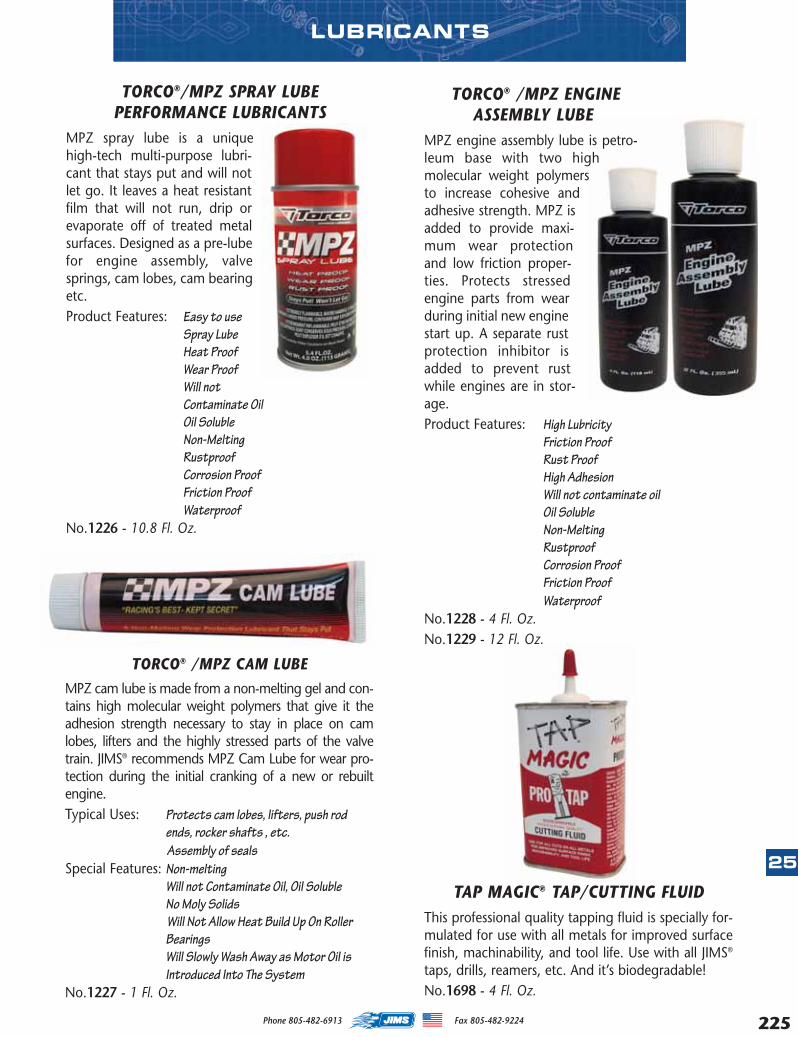
TORCO® /MPZ CAM LUBE
MPZ cam lube is made from a non-melting gel and con-tains high molecular weight polymers that give it theadhesion strength necessary to stay in place on camlobes, lifters and the highly stressed parts of the valvetrain. JIMS® recommends MPZ Cam Lube for wear pro-tection during the initial cranking of a new or rebuiltengine.Typical Uses: Protects cam lobes, lifters, push rod
ends, rocker shafts , etc.Assembly of seals
Special Features: Non-meltingWill not Contaminate Oil, Oil SolubleNo Moly SolidsWill Not Allow Heat Build Up On RollerBearingsWill Slowly Wash Away as Motor Oil isIntroduced Into The System
No.1227 - 1 Fl. Oz.
LUBRICANTS
TAP MAGIC® TAP/CUTTING FLUIDThis professional quality tapping fluid is specially for-mulated for use with all metals for improved surfacefinish, machinability, and tool life. Use with all JIMS®
taps, drills, reamers, etc. And it’s biodegradable!No.1698 - 4 Fl. Oz.
TORCO® /MPZ ENGINEASSEMBLY LUBE
MPZ engine assembly lube is petro-leum base with two highmolecular weight polymersto increase cohesive andadhesive strength. MPZ isadded to provide maxi-mum wear protectionand low friction proper-ties. Protects stressedengine parts from wearduring initial new enginestart up. A separate rustprotection inhibitor isadded to prevent rustwhile engines are in stor-age.Product Features: High Lubricity
Friction ProofRust ProofHigh AdhesionWill not contaminate oilOil SolubleNon-MeltingRustproofCorrosion ProofFriction ProofWaterproof
No.1228 - 4 Fl. Oz.No.1229 - 12 Fl. Oz.
TORCO®/MPZ SPRAY LUBEPERFORMANCE LUBRICANTS
MPZ spray lube is a uniquehigh-tech multi-purpose lubri-cant that stays put and will notlet go. It leaves a heat resistantfilm that will not run, drip orevaporate off of treated metalsurfaces. Designed as a pre-lubefor engine assembly, valvesprings, cam lobes, cam bearingetc.Product Features: Easy to use
Spray LubeHeat ProofWear ProofWill notContaminate OilOil SolubleNon-MeltingRustproofCorrosion ProofFriction ProofWaterproof
No.1226 - 10.8 Fl. Oz.
25
225Phone 805-482-6913 Fax 805-482-9224
MASTER BACK SEC 2015 CATALOG.qxp:Layout 1 10/30/14 8:07 AM Page 225

226
26
Phone 805-482-6913 Fax 805-482-9224
JIMS® BRAND T-SHIRTS - PIN-UP GIRLMaterial is pre-shrunk 100% cotton.
WHITENo.2161 - MediumNo.2162 - LargeNo.2163 - X LargeNo.2164 - XX Large
BLACKNo.2165A - MediumNo.2166A - LargeNo.2167A - X LargeNo.2168A - XX Large
JIMS® BRAND T-SHIRTS - FLYWHEELSMaterial is pre-shrunk 100% cotton.
WHITENo.1106W - MediumNo.1107W - LargeNo.1108W - X LargeNo.1109W - XX Large
BLACKNo.1106 - MediumNo.1107 - LargeNo.1108 - X LargeNo.1109 - XX Large
JIMS® BRAND T-SHIRTS - SKULLSMaterial is pre-shrunk 100% cotton.
GREYNo.2552 - MediumNo.2553 - LargeNo.2554 - X LargeNo.2555 - XX Large
CLOTHING
JIMS® BRAND T-SHIRTS - PISTONSMaterial is pre-shrunk 100% cotton.
BLACKNo.2540 - MediumNo.2541 - LargeNo.2542 - X LargeNo.2543 - XX Large
MASTER BACK SEC 2015 CATALOG.qxp:Layout 1 10/30/14 8:07 AM Page 226

227
26
Phone 805-482-6913 Fax 805-482-9224
CLOTHING
JIMS® TRIBAL FLAME LOGO T-SHIRTWHITE
No.2544 - MediumNo.2545 - LargeNo.2546 - X LargeNo.2547 - XX Large
BLACKNo.2548 - MediumNo.2549 - LargeNo.2550 - X LargeNo.2551 - XX Large
JIMS® TRIBAL FLAME LOGO SWEATSHIRTBLACK
No.2584 - MediumNo.2585 - LargeNo.2586 - X LargeNo.2587 - XX Large
JIMS® BRAND T-SHIRTS - 131”
BLUENo.1238 - MediumNo.1239 - LargeNo.1240 - X LargeNo.1241 - XX Large
JIMS® BRAND T-SHIRTS - TOOLS
BLACKNo.2556 - MediumNo.2557 - LargeNo.2574 - X LargeNo.2579 - XX Large
MASTER BACK SEC 2015 CATALOG.qxp:Layout 1 10/30/14 8:07 AM Page 227

228
26
JIMS® LOGO DICKIES WORK SHIRTNAVY BLUE
No.2575 - MediumNo.2576 - LargeNo.2577 - X LargeNo.2578 - XX Large
CLOTHING
JIMS® TWIN CAM® FLAMEENGINE HOODED SWEATSHIRT
GRAYNo.2558 - MediumNo.2559 - LargeNo.2560 - X LargeNo.2561 - XX Large
JIMS® CHOPPER T-SHIRTMaterial is pre-shrunk 100% cotton.
WHITENo.2588 - MediumNo.2589 - LargeNo.2590 - X LargeNo.2591 - XX Large
BLACKNo.2592 - MediumNo.2593 - LargeNo.2594 - X LargeNo.2595 - XX Large
JIMS® BUY AMERICAN ZIPPERSWEATSHIRT
BLACKNo.2536 - MediumNo.2537 - LargeNo.2538 - X LargeNo.2539 - XX Large
Phone 805-482-6913 Fax 805-482-9224
MASTER BACK SEC 2015 CATALOG.qxp:Layout 1 10/30/14 8:08 AM Page 228

NUMERIC INDEX
229
0178-1010 ..................113
0178-1012...................113
0178-1033...................113
1000-0001.....................12
1000-0002.....................12
1000-0003.....................12
1000-0010.....................13
1000-0011.....................13
1000-0012.....................12
1000A..........................167
1001............................146
1003............................162
1004A..........................193
1005............................202
1006T..........................218
1007............................218
1008-5.........................218
1008-TS.......................218
1010............................161
1011-36TB ..................157
1012-70TB ..................157
1013-54TB ..................159
1014............................200
1015-37TB ..................159
1016-37TB ..................159
1017-37TB ..................157
1018-37TB ..................159
1019............................108
1020............................108
1021............................108
1022............................218
1023-70.......................153
1025-15.........................89
1029-53B ......................64
1029-53C ......................64
1029AP .........................65
1029AP2 .......................65
1029AP5 .......................65
1029-TS.......................176
1030-TS.......................176
1031-TS.......................176
1032-TS.......................176
1033-TS.......................176
1034............................173
1035............................108
1043..............................60
1041-TC ......................158
1044-TS.......................180
1045RR..........................32
1045-TS.......................180
1046..............................66
1046-36A ......................89
1046P............................66
1047-TP.......................184
1048....................184, 206
1050............................204
1051............................161
1052............................187
1053............................186
1055............................149
1056............................108
1057............................220
1058............................148
1059............................215
1060............................108
1061............................108
1062............................108
1067............................108
1069............................215
1073............................166
1077............................201
1080............................221
1081............................221
1083....................170, 224
1084....................170, 224
1087-2.........................138
1090....................132, 145
1092C............................61
1092K............................61
1093SP1K......................44
1093SP2K......................44
1093SP3K......................44
1093SP4K......................44
1094..............................61
1094-C ..........................61
1094-CK ........................61
1094-K ..........................61
1095..............................60
1095C............................60
1097....................157, 159
11020K........................118
11057K........................118
1106............................226
11067K........................118
1106W ........................226
1107............................226
1107W ........................226
1108............................226
1108W ........................226
1109............................226
1109W ........................226
1110............................159
1111............................159
11161..........................118
1130............................193
1133......................38, 147
1134 ..............................IV
1135 ..............................IV
1136 ..............................IV
1138............................217
1139............................217
1140............................217
1141............................217
1142............................217
1144............................217
1145............................217
1146............................177
1147............................143
1148............................161
1149............................139
1150......................38, 147
1151......................38, 147
1152......................38, 147
1153......................38, 147
1154......................38, 147
1155......................38, 147
1156......................38, 147
1158............................161
1159............................139
1160..............................33
1162............................216
1163............................171
1164............................163
1167............................171
1168............................189
1169............................144
1169-1.........................144
1170............................206
1171............................187
1171-1.........................187
1171-2.........................187
1171-3.........................187
1172............................162
12013AK .....................126
12035AK .....................126
1205..............................63
1208-1316...................166
1208-3530.....................10
1208-3535.....................10
1226............................225
1227............................225
1228............................225
1229............................225
1235............................164
1236............................165
1238............................227
1239............................227
1240............................227
1241............................227
1249............................139
1250............................148
1251............................148
1252............................148
1253............................148
1254............................148
1255............................165
1256............................165
1268K..........................125
1269K..........................125
1270K..........................125
1271K..........................125
1275............................177
1276............................162
1277............................153
1279............................151
1280............................153
1281............................177
1283............................154
1284............................161
1285............................154
1286-1354.....................18
1286-1806.....................18
1288............................178
1290............................156
NUMERIC INDEX
Phone 805-482-6913 Fax 805-482-9224
MASTER BACK SEC 2015 CATALOG.qxp:Layout 1 10/30/14 8:08 AM Page 229

1300..............................42
1301..............................42
1302..............................43
1307..............................43
1308..............................43
1308-1316...................166
1308-3530.......................9
1308-3535.......................9
1309..............................42
1310A............................36
1310B............................36
1311..............................36
1312..............................36
1313..............................36
1313A............................36
1314..............................36
1314S............................36
1315..............................36
1315S............................36
1317..............................42
1320..............................37
1322..............................37
1323..............................37
1326..............................38
1326-1...........................38
1326-2...........................38
1326-3...........................38
1328..............................38
1328-1...........................38
1328-2...........................38
1328-4...........................38
1340..............................39
1341..............................39
1342..............................39
1342A............................39
1343..............................39
1344..............................39
1346..............................39
1347..............................39
1348..............................39
1349..............................42
1350K............................41
1351K............................41
1352K............................41
1353K............................41
1354K............................41
1355K............................41
1356..............................42
1357..............................39
1358S............................39
1359..............................42
1360..............................42
1361..............................47
1361G ...........................47
1362..............................47
1362G ...........................47
1363..............................47
1363G ...........................47
1364..............................47
1364G ...........................47
1368..............................43
1369..............................43
1370..............................43
1371..............................43
1372..............................43
1373..............................43
1374..............................43
1375..............................43
1376..............................43
1377..............................42
1383..............................40
1384..............................40
1385..............................40
1390............................156
1400............................169
1408......................27, 168
1408-3530.....................10
1408-3535.....................10
1409......................27, 168
1410............................155
1411............................155
1412............................155
1413............................155
1414............................206
1417............................173
1419............................160
1420............................160
1430............................169
1431............................169
1432............................169
1433............................169
1437..............................67
1438..............................67
1439..............................67
1440..............................67
1441..............................67
1442..............................67
1444..............................67
1457..............................27
1491..............................18
1493..............................18
1501..............................18
1501B............................18
1508-3530.......................9
1508-3535.......................9
1519..............................18
1520..............................18
1521..............................18
1522..............................18
1523..............................18
1524..............................18
1525..............................18
1526..............................18
1527..............................18
1528..............................18
1548..............................18
1549..............................18
1550..............................18
1551..............................18
1555..............................30
1555A............................30
1555B............................30
1558..............................30
1558A............................30
1558B............................30
1561..............................30
1561A............................30
1561B............................30
1576..............................30
1576A............................30
1576B............................30
1584..............................30
1584B............................30
1602K............................29
1603........................18, 29
1604K............................29
1607..............................29
1607B............................29
1608..............................29
1608-3530.....................10
1608-3535.....................10
1608A............................29
1608B............................29
1611..............................18
1613..............................18
1614..............................18
1615..............................18
1616..............................18
1617..............................18
1618..............................18
1620..............................29
1622..............................18
1623..............................18
1624..............................18
1625..............................18
1626..............................18
1627..............................18
1628..............................18
1629..............................18
1658............................203
1664............................203
1665............................185
1666............................185
1667............................193
1672............................177
1674............................193
1698............................225
1698E ............................91
1698EB..........................91
1698L ............................91
1698LB..........................91
1699E ............................91
1699EB..........................91
1699L ............................91
1699LB..........................91
1700............................204
1705............................149
1706............................156
1707............................208
1708............................121
1708-3530.......................9
1708-3535.......................9
1709............................180
1710............................182
NUMERIC INDEXNUMERIC INDEX
230 Phone 805-482-6913 Fax 805-482-9224
MASTER BACK SEC 2015 CATALOG.qxp:Layout 1 10/30/14 8:08 AM Page 230

NUMERIC INDEX
1711E ............................91
1711EB..........................91
1711L ............................91
1711LB..........................91
1719..............................92
1720............................198
1725............................207
1726-1.........................161
1726-2.........................161
1726-3.........................161
1731..............................32
1732..............................32
1733............................121
17428-57K ....................34
17428-83K ....................34
17428-CCK....................34
17435-57B ....................33
1743............................208
1744..............................92
1745............................182
1746 ..............................XI
1747 ..............................XI
1748 ..............................XI
1752..............................90
1752B............................90
1753..............................90
1753B............................90
1754..............................90
1754B............................90
1755..............................90
1755B............................90
1757....................134, 142
1758....................134, 142
1761............................220
17611-66B ....................33
17611-83.......................33
17611-83H ....................33
1762............................220
1763............................142
1764............................142
1765............................165
1766............................216
1767............................216
1768............................216
1769............................188
1770............................142
1771............................220
1772............................220
1773............................220
1774............................148
1775............................206
1775............................221
1777............................206
1800........................52, 54
1800-2.....................52, 54
1800-5.....................52, 54
1803........................52, 58
1807........................51, 57
1808........................51, 57
1808-3530.....................11
1808-3535.....................11
1809........................51, 57
1810........................51, 57
1811......................51, 147
1820........................52, 58
1821........................52, 58
1822........................52, 58
1827................................II
1828................................II
1829................................II
18526-89SA ..................58
18526-89SA1 ................58
18526-89SA5 ................58
18526-PG ......................57
18526-PG1 ....................57
18526-PG2 ....................57
18526-PG5 ....................57
18534-29A ....................59
18534-CP ......................59
18554-57K ....................59
18555-36K ....................59
18556-40K ....................59
18570-38K ....................59
18607-57A ....................63
18607-57AC ..................63
18607-57AR ..................63
1880..............................22
1881..............................21
1882..............................21
1883..............................21
1884..............................21
1886..............................21
1888..............................21
1905..............................27
1908-3530.....................11
1908-3535.....................11
1937..............................19
1938..............................19
1941..............................19
1942..............................19
1943..............................19
1944..............................19
1945..............................19
1946..............................19
1957..............................20
1958..............................20
1959..............................20
1960..............................20
1972..............................24
1973..............................24
1974..............................24
1976..............................23
1977..............................23
1978..............................23
1979..............................23
1980..............................23
1981..............................23
1982..............................23
1983..............................23
1984..............................23
1985..............................23
1986..............................23
1987..............................23
2008-3530.....................10
2008-3535.....................10
2043............................205
2044............................205
2049............................205
2051...............................III
2052...............................III
2053...............................III
2054...............................III
2108-3530.......................9
2108-3535.......................9
2121A..........................142
2122A..........................142
2144............................166
2161............................226
2162............................226
2163............................226
2164............................226
2165A..........................226
2166A..........................226
2167A..........................226
2168A..........................226
2169............................126
2178K............................34
2179K............................34
2180K............................34
2181K..........................120
2182K..........................120
2183K..........................122
2186K............................83
2187K............................83
2188............................152
2189............................200
2196K............................82
2197K............................82
2220............................112
2201K............................72
2201K..........................158
2208-3530.......................8
2208-3535.......................8
2226............................114
2228..............................28
2229..............................28
2230..............................28
2231..............................28
2232............................207
2233............................187
2234............................189
2235............................190
2237............................185
2239..............................70
2239C............................70
2239L ............................70
2239LC..........................70
2240............................144
2240-11-4....................144
2240-19.......................144
2243............................157
2244............................205
2245............................191
2246............................182
231Phone 805-482-6913 Fax 805-482-9224
MASTER BACK SEC 2015 CATALOG.qxp:Layout 1 10/30/14 8:08 AM Page 231

NUMERIC INDEX
2249............................154
2250............................208
2251............................207
2256............................195
2256-1.........................181
2260............................194
2262............................194
2280............................154
2281............................158
2283............................199
2300..............................68
2301 .......................XII, 68
2303..............................69
2305............................180
2311..............................69
2312............................189
2315............................189
2316............................189
2317............................189
2318............................189
2324............................181
2326B..........................110
2326CB .......................110
2327B..........................110
2327CB .......................110
2336................................V
2337..............................93
2337S............................93
2337ST..........................93
2338..............................93
2338S............................93
2340................................V
2341............................145
2344..............................13
2346............................196
2347-7.........................110
2347-75C ....................110
2347-7B ......................110
2347-7C ......................110
2347-7CB ....................110
2357............................150
2358K ...................63, 125
2359K ...................63, 125
2361............................221
2362............................203
2369..............................46
2370..............................56
2371CH.......................111
2371CK .......................111
2371P..........................111
2380..............................45
2384............................119
2385-7.........................106
2386............................106
2386-7.........................106
2388............................181
23901-81.......................77
23909-80.......................79
2392............................148
2394......................68, 111
2395......................68, 111
2396 ...............XII, 68, 111
23960-29.......................76
23960-54.......................76
23960-80A3 ..................76
23961-411.....................75
23961-412.....................75
23961-413.....................75
23961-41S.....................75
23961-41ST3.................75
23961-80A2 ..................75
23961-80A3 ..................75
23961-80AS ..................76
23962-40.......................75
23966-36.......................77
23966-54A ....................77
23967-54A ....................77
23969-83.......................77
23974-873.....................75
23975-873.....................75
2398 ...............XII, 68, 111
2400........................45, 55
24000-29.......................79
24000-57.......................79
24000-75.......................79
24000-80.......................79
24001-30.......................79
24001-56.......................79
24001-65.......................79
24001-70.......................79
24001-72.......................79
24002-70.......................81
24003-55.......................77
24005-37.......................80
24005-57.......................80
24005-80.......................80
24006-37.......................80
24006-54A ....................80
24006-58.......................80
24006-73.......................80
24006-80/83 .................80
24006-83L.....................80
24006-87.......................80
24007-39.......................80
24010-BLU ....................84
24010-BR ......................84
24010-GR......................84
24010-OR......................84
24010-RE.......................84
24010-WH.....................84
24010-YE.......................84
24016-80.......................77
24017-80.......................77
24020-51K ....................82
24022-90.......................77
24023-36.......................77
24023-36.......................77
24023-54.......................77
24029-KIT .....................81
2404..............................46
24040-78.......................84
24041-78.......................84
24042-78.......................84
24043-78.......................84
24044-78.......................84
24045-78.......................84
24046-78.......................84
2406..............................63
2411..............................65
2411C............................65
2413..............................70
2414..............................70
2415..............................81
2416..............................45
2418..............................62
2419..............................62
2428..............................65
2429..............................74
2430..............................74
2431..............................74
2427-1...........................59
2428-5...........................65
2432..............................74
2433..............................81
24331-36.......................89
24334-36.......................89
24335-36.......................89
2434..............................81
2435..............................92
2436..............................92
24366-51K ....................85
2437..............................80
2438..............................74
2439..............................80
2440..............................85
2442..............................85
2443..............................85
2444..............................85
2445..............................85
2446..............................85
2447..............................85
2448..............................85
2449..............................85
2450..............................85
2451..............................85
2452..............................85
2453..............................85
2454..............................85
2455..............................85
2456-1.....................54, 57
2457-1.....................54, 57
2458-1.....................54, 57
24585-39.......................88
24585-57.......................88
24587-39.......................88
2459-1...........................55
24595-40.......................88
24597-40.......................88
24599-40.......................88
24599-55.......................88
24599-58.......................88
24599-58A ....................88
24599-58B ....................88
24600-58.......................88
232 Phone 805-482-6913 Fax 805-482-9224
MASTER BACK SEC 2015 CATALOG.qxp:Layout 1 10/30/14 8:08 AM Page 232

NUMERIC INDEX
24600-58A ....................88
24600-58B ....................88
2460-1...........................55
24601-40.......................88
24601-55.......................88
24601-5810...................88
24601-5832...................88
24601-58A10 ................88
24601-58A32 ................88
24601-58B10 ................88
24601-58B32 ................88
24610-39.......................88
2461-1...........................55
24612-39.......................88
2462-1...........................56
24621-40.......................88
24623-4032...................88
24626-87.......................87
24628-87.......................87
2463-1...........................56
2464-1...........................56
24641-87.......................87
24643-87.......................87
2465-1.....................54, 58
2466-1.....................54, 58
2467-1.....................54, 58
24703-54B ....................81
2471-1...........................58
2472-1...........................58
2473-1...........................58
2474-1...........................56
2475-1...........................56
2476-1...........................56
2480K............................83
2481K............................82
2482K............................82
2483K............................83
2488K............................83
2489K............................83
2505..............................93
2506..............................93
2507..............................93
2508..............................93
2509..............................93
2510..............................93
2511..............................93
2512..............................93
2513..............................93
25225-70BK ................125
25225-70BK ................125
25225-93K ..................125
25225-93K ..................125
25254-93A ....................70
25258-80A ....................70
2528............................120
2530............................109
2536............................228
2537............................228
2538............................228
2539............................228
2540............................226
2541............................226
2542............................226
2543............................226
2544............................227
2545............................227
2546............................227
2547............................227
2548............................227
2549............................227
2550............................227
2551............................227
2552............................226
2553............................226
2554............................226
2555............................226
2556............................227
2557............................227
2558............................228
25581-36.......................72
25581-70.......................72
25581-705.....................72
25581-80AB ..................72
25582-36.......................73
25582-365.....................73
25582-54/73 .................73
25582-54/735 ...............73
25582-80AB ..................73
25582-93.......................73
25582-935.....................73
25586-37.......................72
25586-375.....................72
25588-57.......................72
25588-575.....................72
2559............................228
25593-57.......................73
25593-74.......................73
25597-36.......................72
25597-365.....................72
2560............................228
2561............................228
2574............................227
2575............................228
2576............................228
2577............................228
2578............................228
25785-30A ....................73
2579............................227
25791-36.......................82
25791-KIT .....................82
2584............................227
2585............................227
25856-36.......................82
25856-KIT .....................82
2586............................227
2587............................227
2588............................228
2589............................228
2590............................228
2591............................228
2592............................228
2593............................228
2594............................228
2595............................228
2607..............................56
2608..............................56
2608-3530.......................8
2608-3535.......................8
2609..............................56
2610..............................56
26207-83.......................92
2626-1...........................59
26262-80.......................92
26315-68A ....................92
26317-68A ....................92
26326-62A ....................92
26328-74.......................92
26345-73.......................92
26346-36.......................92
26346-69/70 .................92
26349-84.......................92
26400-82.......................92
2808-3530.....................11
2808-3535.....................11
3000........................44, 68
3001........................44, 68
3002........................44, 68
3003........................44, 68
3004........................44, 68
3005........................44, 68
3200............................164
3201............................164
32591-70K ..................125
33031-36.....................108
33031-76E...................108
33031-76L...................108
33031-80.....................108
33071-73.....................213
33096-54AL.................122
33096-54B ..................122
33099-52A ..................122
33119-79A ..................118
33288-37.....................122
33288-375...................122
33334-79.....................117
33334-85.....................117
33344-94.....................117
33416-80............152, 181,
............................207, 213
33428-78.....................202
33438-501...................122
33438-502...................122
33442-57A ..................122
33442-73.....................122
33443-84.............160, 186
33715-85AC ................119
33902-98.....................109
33904-00.....................109
34088-87.....................120
34091-85.....................116
34140-36.....................120
34186-76.....................120
34623-83.....................163
34643-84.....................146
233Phone 805-482-6913 Fax 805-482-9224
MASTER BACK SEC 2015 CATALOG.qxp:Layout 1 10/30/14 8:08 AM Page 233
NUMERIC INDEX
34731-84.....................146
34734-80.....................202
34740-84.....................146
34761-84.....................192
34782-91.....................202
34810-84.....................201
348-15...........................76
34902-84.....................196
34904-86K ..................126
35025-79B ..................112
35026-79K ..................117
35039-80.....................113
35042-79.....................113
35042-85.....................113
35042-91.....................113
35051-89.....................115
35058-79K ..................117
35064-79K ..................117
35087-99K ..................118
35094-65.....................117
35105-52.....................116
35105-525...................116
35125-37.....................116
35125-3710.................116
35125-372...................116
35125-375...................116
35211-91B ..................121
35316-80.....................198
35322-38.....................117
35614-65.....................113
35614-76.....................113
35614-80.....................113
35622-79C ..................112
35625-79B ..................112
35626-79K ..................117
35632-79.....................113
35632S........................113
35652-79K ..................126
35789-36.....................117
35791-36.....................117
35820-86.....................203
35960-54.....................114
35961-52.....................114
36801-87K ..................126
37047-91-5..................178
37047-91-6..................178
38515-90.....................192
38515-91.....................192
39361-69.....................183
3998K............................89
3999..............................85
4015..............................22
4017..............................22
40250-94A ..................121
40250-94AK ................121
40520-63.....................117
41043............................76
43067............................76
500..............................222
5001............................121
5001K..........................121
501..............................222
502..............................222
503..............................222
504..............................222
505..............................222
506..............................222
507..............................222
508..............................222
509..............................222
5100............................122
5101............................122
5102............................122
5103............................122
5104............................122
5105............................122
511..............................222
512..............................222
513..............................222
514..............................222
5209..............................15
5210..............................15
5215..............................15
5216..............................15
5221..............................15
5222..............................15
5275..............................17
5276..............................17
5285..............................17
5286..............................17
5287..............................17
5288..............................17
5400.................................I
5401.................................I
5402.................................I
5447.................................I
5457 ............................I, V
5462.................................I
6003K..........................118
6030..............................60
6031..............................60
6032........................60, 68
6033 .................XII, 60, 68
6035..............................67
6036..............................67
6037..............................67
6038..............................69
6039..............................69
604 ..............................VIII
6040..............................69
6050..............................69
6051..............................69
6052..............................69
621..............................109
635................................94
636................................94
637................................94
638................................94
639................................95
640................................95
641................................95
642................................95
643................................95
644................................95
645................................95
646................................95
647................................95
648................................95
649................................95
650................................95
651................................95
652................................94
653................................94
700................................26
701................................26
702................................26
703................................26
704................................16
705................................16
706................................16
707................................16
720................................26
721................................26
725................................26
727K..............................27
729 ................................IX
737 .................................X
738 ..............................VIII
739 ................................IX
740 ...............................VII
741 ...............................VII
742 .................................X
742k................................X
743 .................................X
744 .................................X
74420-94.....................119
74437-96.....................119
745 .................................X
746 .................................X
747 ................................IX
750..............................143
751..............................143
7515K..........................118
752..............................143
753..............................176
754 ................................XI
755..............................135
756..............................135
757 ..............................VIII
758..............................142
759..............................186
761..............................136
761..............................136
762..............................136
763..............................136
764..............................219
765..............................131
766..............................131
767..............................195
768..............................195
769..............................162
770..............................148
771..............................148
772..............................131
234 Phone 805-482-6913 Fax 805-482-9224
MASTER BACK SEC 2015 CATALOG.qxp:Layout 1 10/30/14 8:08 AM Page 234

NUMERIC INDEX
773..............................137
774..............................207
776..............................132
776..............................214
777..............................137
778..............................141
779..............................172
780..............................138
781..............................216
782..............................138
783..............................136
784..............................135
785..............................175
786..............................195
787..............................152
788..............................149
789................................50
789..............................147
7999............................109
7999B..........................109
7999P..........................109
800..............................126
8000............................102
8000C6........................102
801..............................126
8001............................102
8001C6........................102
802..............................126
8002............................102
8002C6........................102
803..............................126
8003............................102
8003C6........................102
804..............................126
8004............................102
8004C6........................102
8013............................109
8015............................113
8016............................113
8028............................104
8028C6........................104
8030............................104
8030C6........................104
8041K .................119, 126
8042K..........................119
8044............................113
8045............................113
8046............................113
8047............................113
8070............................120
8085............................105
8085L ..........................105
8088............................103
8096............................109
8096P..........................109
8100............................106
8101............................105
8102............................119
8103............................119
8111............................102
8112............................102
8126............................119
8131............................107
8132............................107
8133............................107
8134............................107
8150..............................71
816..............................126
817K............................126
8235..............................99
8236..............................99
824..............................123
8248..............................98
8249..............................98
8250..............................98
8251..............................98
8252..............................98
8253..............................98
8259..............................98
826..............................123
8260..............................98
8266..............................98
8267..............................98
8269............................107
827..............................123
8273............................101
8274............................101
8275............................101
8277............................107
8279............................101
828..............................123
8280............................101
8282............................101
8283............................101
8284............................101
8291............................112
8292............................112
8294............................112
8296............................112
8297............................112
8298............................112
8299............................112
831..............................123
833..............................123
834..............................123
835..............................123
8360............................119
837..............................124
8375..............................96
8376..............................96
8379..............................96
838..............................124
8380..............................97
8381..............................97
8382..............................96
8385 ..............................IV
8387 ..............................IV
839..............................124
840..............................124
841..............................124
842..............................124
843..............................124
844..............................124
851..............................125
852..............................125
853..............................125
854..............................125
855..............................125
857.........................26,124
858................................26
859................................26
870................................26
871................................26
872................................26
873................................26
873..............................124
881..............................126
882..............................126
883..............................126
8876A..........................114
890......................107, 126
8904............................115
8905............................114
891......................107, 126
892......................107, 126
893..............................126
8960............................114
8961............................114
8977............................115
8978............................115
899..............................212
8990K............................71
8991K............................71
8992K..........................115
8996............................115
8998K..........................115
8999CK .......................111
8999PK........................111
900..............................197
901..............................198
902..............................218
9020............................115
904..............................214
905..............................214
9057..............................71
9058..............................71
906..............................209
908......................149, 164
908..............................164
9084............................116
9084A..........................116
9085............................116
9086............................116
9095............................116
9096............................116
9097............................116
910..............................165
911..............................199
9118............................114
913 ................................VI
915..............................172
9150A............................86
9150AA .........................86
9152A............................86
235Phone 805-482-6913 Fax 805-482-9224
MASTER BACK SEC 2015 CATALOG.qxp:Layout 1 10/30/14 8:08 AM Page 235

NUMERIC INDEX
9154A............................86
9156A............................86
9158A............................86
916..............................183
9160A............................86
9161..............................86
917........................44, 145
918..............................210
9180..............................86
9181..............................86
9182..............................86
9183..............................86
9184..............................86
9185..............................86
9186A............................86
9186AA .........................86
919..............................210
9198K............................71
920..............................207
921..............................211
922..............................220
9220AA .........................87
9221A............................87
9222A............................87
9223A............................87
9224A............................87
9225A............................87
923..............................211
924..............................211
925..............................211
926..............................211
927..............................221
928..............................209
930..............................166
931..............................166
932..............................166
933..............................221
934..............................188
935..............................188
936..............................215
937..............................146
938..............................146
939 ........................VI, 212
940..............................175
941..............................188
9417..............................86
9418..............................86
942..............................140
9422..............................86
9423..............................86
9424..............................86
9425..............................86
9426..............................86
943..............................140
944 ................................XI
9441A............................86
9441AA .........................86
9442A............................86
9443A............................86
9444A............................86
9445A............................86
9446A............................86
945..............................216
9450A............................86
94547-80A ..................181
94547-80B ..................181
94555-55A ..................185
94557-55A ..................189
946..............................216
94630-67.....................216
94660-37A ..................194
947..............................213
948..............................146
94804-57.....................150
94805-57.....................170
949..............................146
950..............................209
951..............................166
952..............................172
953..............................138
954..............................141
955..............................134
95560-57.....................200
95660-42.....................196
95660-77.....................196
95660-85.....................196
956..............................133
956K............................133
957..............................171
95724-57.....................160
95760-57.....................150
95760-TB ....................151
95760-TP.....................159
95760-XL ....................151
958..............................212
959........................27, 133
95960-52C ..................193
95970-32C ..................161
960..............................172
963..............................179
96384-39.....................204
96385-78A ..................204
964..............................210
965........................95, 191
966..............................190
96600-36B ..................145
967..............................190
96710-TL.....................170
96740-36.....................162
96780-32A ..................163
96780-58A ..................163
96781-72.....................163
968..............................189
96830-51.....................185
969..............................135
970..............................209
97081-54.....................178
971........................97, 191
97178-71.....................192
972..............................195
97225-55.....................178
97235-55B ..................183
97272-60.....................152
97273-60.....................152
973..............................179
974..............................174
975..............................174
976..............................174
977..............................205
981..............................197
984..............................199
985..............................203
986..............................202
987..............................197
988........................40, 145
989..............................194
990..............................153
992..............................217
993..............................151
994..............................154
995..............................184
998 ............................201
D180 .............................76
236 Phone 805-482-6913 Fax 805-482-9224
MASTER BACK SEC 2015 CATALOG.qxp:Layout 1 10/30/14 8:08 AM Page 236
237Phone 805-482-6913 Fax 805-482-9224
DISCLAIMERThe words Harley®, Harley-Davidson® and H-D® and all H-D® part numbers and modeldesignations are used in reference only. JIMS® is in no way associated with or author-ized by Harley-Davidson® Motor Co. to manufacture and sell any of the engine partsdescribed in this catalog.The installation of JIMS® parts may void or otherwiseadversely affect your factory warranty. It is the sole and exclusive responsibility ofthe user to determine the suitability of the product for his or her use, and the usershall assume all legal, personal injury risk and liability and all other obligations,duties and risks associated therewith.
RETAIL SALESAs a JIMS® Distributor or Dealer you are assured that we will not sell directly to retailcustomers, and our products will only be available through independently ownedand operated legitimate motorcycle businesses (licensed commercial places of busi-ness serving the general public primarily in the area of motorcycle sales, service,and/or parts and accessories). Retail customers in possession of this catalog will beable to use it for reference only.
SALESJIMS® parts are obtainable from many shops and dealerships throughout the world.If an individual does not have access to one of our dealers, please contact us. Inorder to receive dealer prices, new customers must provide proof of bonafide motor-cycle business operation in the form of a photo copy of Sellers Permit, business let-terhead and/or business card, photograph of storefront and 3 (three) trade/creditreferences, within the motorcycle industry.
TERMSDealers - We gladly accept any size order, however, a service charge of $10.00 willbe added to orders under $100.00. All orders will be sent C.O.D., certified check /money order, Visa® or MasterCard® in the continental USA. Company checks will beaccepted from dealers whose financial histories warrant it. Any orders from outsidethe USA must be prepaid in US funds via wire transfer, a transfer fee will apply, or byVisa® or MasterCard®, a handling fee will apply to all credit card transactions. A$10.00 service charge will be applied to all drop-ship requests.
TERMS & CONDITIONS
MASTER BACK SEC 2015 CATALOG.qxp:Layout 1 10/30/14 8:08 AM Page 237
Phone 805-482-6913 Fax 805-482-9224238
TERMS & CONDITIONS
PRICESThe prices for all JIMS® parts are F.O.B. Camarillo, CA. We reserve the right to changeprices and/or discounts without notice and to bill at the prevailing prices at the timeof shipment. Please check invoice for changes.
ORDERINGOur goal is to handle your order as quickly and efficiently as possible. To help us dothis you will be assigned a dealer representative. Please have your customer number,full purchaser’s name, part numbers, and quantities ready when you call. Orders mayalso be placed in writing or via fax. Special order forms are not necessary. Pleaseinclude, a phone number where you can be reached during business hours, a ship-ping address and shipping preference: UPS - Red (1 day), Blue (2 day), Orange (3day), or Ground. If no preference is indicated, order will be sent UPS ground.
BACKORDERSJIMS® makes an ongoing effort to improve parts availability, however, backorderscannot always be avoided. Items not in stock at the time of order will be placed onbackorder. Once parts are available the customer will be notified (only once) byphone for authorization to ship. Order will be canceled if authorization is notreceived within one week. The customer shall assume responsibility of notifyingJIMS® if the parts are no longer needed. Invoice will show the items that have beenbackordered.
REFUSED SHIPMENTSOrders that are refused or returned to JIMS® for reasons such as “lack of cash onhand” or “no one available to receive shipment”, etc. are subject to a 20% restock-ing fee. Additionally, the customer is liable for all shipping charges. Any restockingfees and shipping charges that total $50.00 or more must be paid before any futurebusiness transactions are made. Charges less than $50.00 will be added to the cus-tomer’s next purchase. After two refused shipments, all future orders will be releasedonly after prepayment of invoice total. A pattern of refused orders may result in ter-mination of customer account.
SHIPPINGPrompt service and accurate orders are our primary consideration. Orders are nor-mally processed and shipped the same day received, provided they are receivedbefore 2:00 p.m. Pacific Standard Time.
MASTER BACK SEC 2015 CATALOG.qxp:Layout 1 10/30/14 8:08 AM Page 238
239Phone 805-482-6913 Fax 805-482-9224
JIMS® ships by United Parcel Service in the continental USA. Overseas customers -Due to the high shipping and customs cost, it is suggested that overseas customerssupply a shipping carrier for all large orders. All others, unless otherwise specified,will be shipped by UPS Express (3-4 day service) or UPS Expedited (5-6 day service).All orders will be shipped prepaid.
RETURNSAll items are carefully packaged and in good condition when shipped. Please inspectproduct immediately upon receipt of shipment. JIMS® must be notified within 5 (five)working days of the receipt of a shipment of any shortages or incorrect shipments.It is advisable to phone JIMS® as problems can often times be corrected more quick-ly with a direct call. Any claims for damages must be made with the carrier and notwith JIMS®. Please be sure to save all boxes and packaging material when filing aclaim and keep them until settlement is made.
QUALITY IS NO PROTECTION AGAINST ABUSE, MISUSE OR NEGLECT.The following qualifications are necessary to receive credit, or to exchange merchan-dise.
1. Call JIMS® before shipping parts back to obtain an RGA number.
2. The parts must be returned within 10 days of receipt.
3. They must be packaged properly to prevent any damage during shipping.Damaged parts due to poor packaging are non-returnable and will be returned tothe owner at the owner’s expense. Repackaged goods using JIMS® containers doesnot always mean the items are packaged properly.
4. All returns must be sent to JIMS® insured and prepaid. No CODs will be accepted.
5. All returns must be accompanied by the return goods authorization number, acopy of the original invoice of purchase and a note explaining the reason for thereturn.
6. Under no circumstances are damaged, altered, rusty, or otherwise unusable partsreturnable. Upon acceptance of the returned parts by JIMS® under the above cri-teria, a 20% restocking fee will be charged.
7. Acceptance of returned goods by our Receiving Department shall not be bindingand has no force or effect unless acceptance is made by us in writing.
TERMS & CONDITIONS
MASTER BACK SEC 2015 CATALOG.qxp:Layout 1 10/30/14 8:08 AM Page 239
Phone 805-482-6913 Fax 805-482-9224240
TERMS & CONDITIONS
WARRANTYAll JIMS® parts are guaranteed to the original purchaser to be free of manufacturingdefects in materials and workmanship for a period of 6 (six) months from the dateof purchase, unless otherwise noted. Merchandise that fails to conform to these con-ditions will be repaired or replaced at JIMS® option if the parts are returned to us bythe purchaser within the 6 (six) month warranty period or within 10 (ten) daysthereafter. In the event warranty service is required, the original purchaser must callor write JIMS® immediately with the problem. Some problems can be rectified by atelephone call and need no further course of action. A part suspected of being defec-tive must not be replaced by a Dealer without prior authorization from JIMS®. If it isdeemed necessary for JIMS® to make an evaluation to determine whether the part isdefective, it must be packaged properly to prevent further damage and be returnedprepaid to JIMS® with a copy of the original invoice of purchase and a detailed letteroutlining the nature of the problem, how the part was used and the circumstancesat the time of failure. If after an evaluation has been made by JIMS® and the part wasfound to be defective, repair, replacement or credit will be granted.
ADDITIONAL WARRANTY PROVISIONS1. JIMS® shall have no obligation in the event a JIMS® part is modified by any otherperson or organization.
2. JIMS® shall have no obligation if a JIMS® part becomes defective in whole or in partas a result of improper installation, improper maintenance, improper use, abnor-mal operation, or any other misuse or mistreatment of the part.
3. JIMS® shall not be liable for any consequential or incidental damages resultingfrom the failure of a JIMS® part, the breach of any warranties, the failure to deliv-er, delay in delivery, delivery in nonconforming condition, or for any other breachof contract or duty between JIMS® and a customer.
4. JIMS® parts are designed exclusively for use in Harley-Davidson® motorcycles.JIMS® shall have no warranty or liability obligation if a JIMS® part is used in anyother application.
5. Any parts which have been replaced for any reason become the property of JIMS®,and will not be returned under any circumstances.
MASTER BACK SEC 2015 CATALOG.qxp:Layout 1 10/30/14 8:08 AM Page 240