Embed Size (px)
Citation preview

5
JET PUMP
90-877837R01 OCTOBER 2002 Page 5-1
JET PUMPSection 5 - Jet Pump
Table of Contents
Special Tools 5-1. . . . . . . . . . . . . . . . . . . . . . . . . . . General Information 5-3. . . . . . . . . . . . . . . . . . . . .
Principles of Operation 5-3. . . . . . . . . . . . . . . . Drive Housing Components 5-4. . . . . . . . . . . . . . . Pinion and Impeller Shaft 5-6. . . . . . . . . . . . . . . . . Nozzle/Rudder Components 5-8. . . . . . . . . . . . . . Servicing Stator, Impeller and Wear Ring 5-10. . .
Disassembly 5-10. . . . . . . . . . . . . . . . . . . . . . . . .
Inspecting Components 5-12. . . . . . . . . . . . . . . Installing Impeller 5-14. . . . . . . . . . . . . . . . . . . . .
Removing Jet Drive From Boat 5-15. . . . . . . . . . . . Drive Housing Disassembly and Reassembly 5-16
Pinion Shaft Removal 5-16. . . . . . . . . . . . . . . . . Impeller Shaft Removal 5-19. . . . . . . . . . . . . . . Shimming Procedures 5-23. . . . . . . . . . . . . . . .
Special Tools
1. Jet Pump Tool Kit 91-809957a1
a
b dc
ab
cd
ef g
h
i
j
k
l
a - Pre-load Kit - Impeller Shaftb - Thread Extender Kit used with Backlash Kitc - Seal Protector - Impeller Shaftd - Impeller Shaft Wrenche - Impeller Nut Socketf - Pinion Gear Location Toolg - Bearing Installer - Press ball bearing and seals into pinion shaft housingh - Bushing Installer - Stator bushings & seali - Seal Installer - Impeller shaft seals in drive housingj - Bearing Installer - Impeller shaft ball beaing in drive housingk - Bearing Cup Installer - Pinion shaft housing and drive housing front coverl - Handle Driver
JET PUMP
Page 5-2 90-877837R01 OCTOBER 2002
2. Backlash Indicator Flag 91-53459
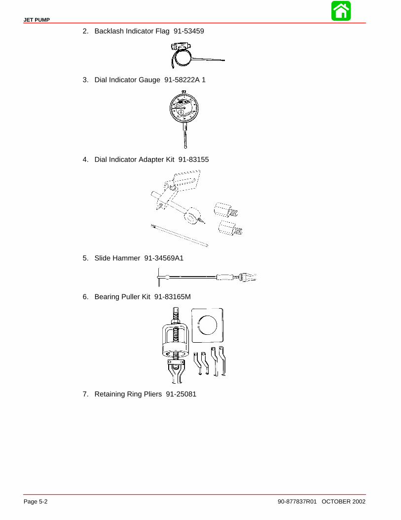
3. Dial Indicator Gauge 91-58222A 1
4. Dial Indicator Adapter Kit 91-83155
5. Slide Hammer 91-34569A1
6. Bearing Puller Kit 91-83165M
7. Retaining Ring Pliers 91-25081
JET PUMP
90-877837R01 OCTOBER 2002 Page 5-3
General Information
NOTE: Due to running changes, some illustrations may not be exactly the same as your drive unit. Service procedures remain the same unless otherwise noted.
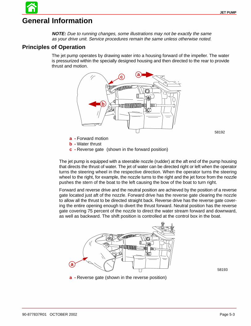
Principles of OperationThe jet pump operates by drawing water into a housing forward of the impeller. The wateris pressurized within the specially designed housing and then directed to the rear to providethrust and motion.
58192
a
b
c
a - Forward motionb - Water thrustc - Reverse gate (shown in the forward position)
The jet pump is equipped with a steerable nozzle (rudder) at the aft end of the pump housingthat directs the thrust of water. The jet of water can be directed right or left when the operatorturns the steering wheel in the respective direction. When the operator turns the steeringwheel to the right, for example, the nozzle turns to the right and the jet force from the nozzlepushes the stern of the boat to the left causing the bow of the boat to turn right.
Forward and reverse drive and the neutral position are achieved by the position of a reversegate located just aft of the nozzle. Forward drive has the reverse gate clearing the nozzleto allow all the thrust to be directed straight back. Reverse drive has the reverse gate cover-ing the entire opening enough to divert the thrust forward. Neutral position has the reversegate covering 75 percent of the nozzle to direct the water stream forward and downward,as well as backward. The shift position is controlled at the control box in the boat.
58193a
a - Reverse gate (shown in the reverse position)

JET PUMP
Page 5-4 90-877837R01 OCTOBER 2002
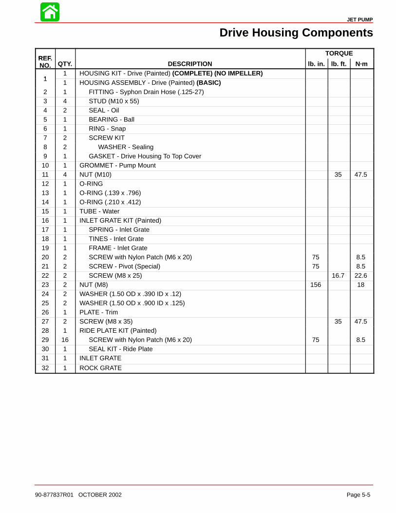
Drive Housing Components
12
48
9
10
11
12131415
16
17
18
20
21
232425
26
27
28
29
30
3
6
7
5
19
22
3
4
66 Loctite 242
RTV 587 Silicone Sealer
66
85
85
31
32
JET PUMP
90-877837R01 OCTOBER 2002 Page 5-5
Drive Housing Components
REFTORQUE
REF.NO. QTY. DESCRIPTION lb. in. lb. ft. N·m
11 HOUSING KIT - Drive (Painted) (COMPLETE) (NO IMPELLER)
11 HOUSING ASSEMBLY - Drive (Painted) (BASIC)
2 1 FITTING - Syphon Drain Hose (.125-27)3 4 STUD (M10 x 55)4 2 SEAL - Oil5 1 BEARING - Ball6 1 RING - Snap7 2 SCREW KIT8 2 WASHER - Sealing9 1 GASKET - Drive Housing To Top Cover10 1 GROMMET - Pump Mount11 4 NUT (M10) 35 47.512 1 O-RING13 1 O-RING (.139 x .796)14 1 O-RING (.210 x .412)15 1 TUBE - Water16 1 INLET GRATE KIT (Painted)17 1 SPRING - Inlet Grate18 1 TINES - Inlet Grate19 1 FRAME - Inlet Grate20 2 SCREW with Nylon Patch (M6 x 20) 75 8.521 2 SCREW - Pivot (Special) 75 8.522 2 SCREW (M8 x 25) 16.7 22.623 2 NUT (M8) 156 1824 2 WASHER (1.50 OD x .390 ID x .12)25 2 WASHER (1.50 OD x .900 ID x .125)26 1 PLATE - Trim27 2 SCREW (M8 x 35) 35 47.528 1 RIDE PLATE KIT (Painted)29 16 SCREW with Nylon Patch (M6 x 20) 75 8.530 1 SEAL KIT - Ride Plate31 1 INLET GRATE
32 1 ROCK GRATE
JET PUMP
Page 5-6 90-877837R01 OCTOBER 2002
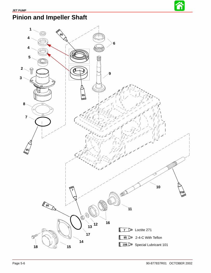
Pinion and Impeller Shaft
1
2
4
3
5
7
6
8
9
10
11
1213
1415
16
17
18
4
7 Loctite 271
95 2-4-C With Teflon
108 Special Lubricant 101
7
95
95
108
95
95

JET PUMP
90-877837R01 OCTOBER 2002 Page 5-7
Pinion and Impeller Shaft
REFTORQUE
REF.NO. QTY. DESCRIPTION lb. in. lb. ft. N·m
1 1 RING - Rubber
2 4 SCREW (M8 x 25) 180 20.5
3 1 HOUSING ASSEMBLY - Pinion Shaft (Painted)
4 2 SEAL - Pinion Shaft Housing
5 1 BEARING - Ball
6 1 BEARING SET (Cone And Cup)
7 1 O-RING
AR SHIM (.002)
AR SHIM (.004)
8 AR SHIM (.005)
AR SHIM (.0075)
AR SHIM (.010)
9 1 GEAR/SHAFT ASSEMBLY - Pinion
10 1 SHAFT - Impeller
11 1 GEAR - Impeller Shaft
12 1 WASHER
13 1 NUT (M14) 90 122
AR SHIM (.002)
AR SHIM (.004)
14 AR SHIM (.005)
AR SHIM (.0075)
AR SHIM (.010)
15 1 COVER ASSEMBLY - Impeller Shaft (Painted)
16 1 BEARING SET (Cone And Cup)
17 1 O-RING
18 4 SCREW (M8 x 25) 180 20.5
JET PUMP
Page 5-8 90-877837R01 OCTOBER 2002
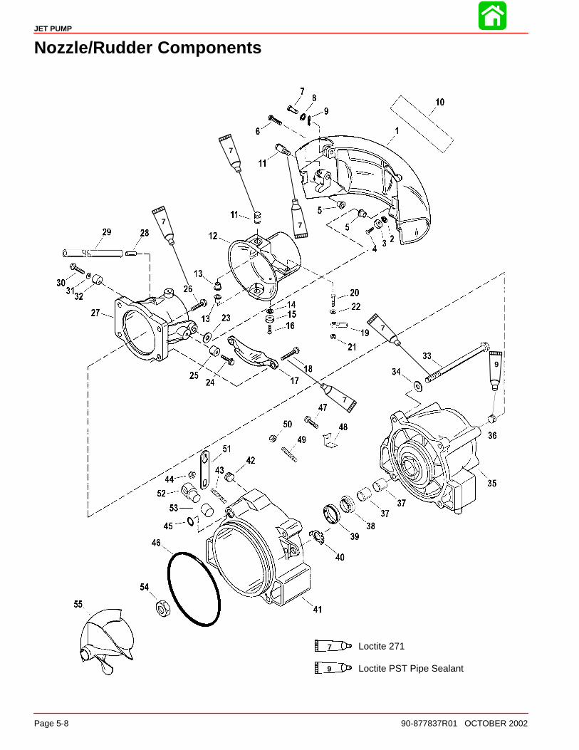
Nozzle/Rudder Components
7 Loctite 271
7
7
7
7
7
Loctite PST Pipe Sealant9
9

JET PUMP
90-877837R01 OCTOBER 2002 Page 5-9
Nozzle/Rudder Components
REFTORQUE
REF.NO. QTY. DESCRIPTION lb. in. lb. ft. N·m
1 1 REVERSE GATE KIT (Painted)2 1 LOCKWASHER (.250 Internal)3 1 ANODE4 1 SCREW (M6 x 20) 70 85 2 BUSHING - Pivot6 2 PIN - Trilobe7 1 PIN - Clevis (.250 x 1.13)8 1 WASHER9 1 PIN - Cotter10 1 DECAL - Reverse Gate (Powered By Mercury)11 4 BOLT (Special) - Pivot 50 6812 1 RUDDER KIT (Painted)13 2 BUSHING - Pivot14 1 LOCKWASHER (.250 Internal)15 1 ANODE16 1 SCREW (M6 x 20) 70 817 1 ANODE (With Bushings In Casting)18 2 SCREW (M10 x 45) 35 4719 1 END KIT - Swivel20 1 BOLT AND NUT KIT21 1 NUT (.250-20)22 1 WASHER23 2 WASHER (Special)24 1 SCREW (M8 x 25)25 1 STOP - Non Adjustable26 2 SCREW (M10 x 35) 35 4727 1 NOZZLE ASSEMBLY - With Pivot Bushings (Painted)28 1 FITTING - Nozzle29 1 HOSE - Syphon (12.250 Inches)30 1 SCREW (M8 x 30) 35 4731 1 WASHER32 1 STOP - Reverse Gate33 4 SCREW (M10 x 150)34 4 WASHER35 1 STATOR ASSEMBLY (Painted)36 2 PLUG - Pipe (.250-18)37 2 BUSHING - Stator Rear38 1 SEAL39 1 PROTECTOR - Seal40 1 TAB WASHER41 1 RING KIT - Wear (Painted)42 1 PLUG - Pipe (.750-14)43 2 STUD (M6 x 36) (Version1–Top and Bottom Holes)44 2 NUT (M6) (Version 1–Top and Bottom Holes)45 1 O-RING46 1 O-RING47 1 SCREW (M6 x 25) (Version 11–Bottom Hole)48 1 TAB (Special) (Version 11–Bottom Hole)49 1 STUD (M6 x 36) (Version II–Top Hole)50 1 NUT (M6) (Version II–Top Hole)51 1 LATCH - Retainer Shift Cable52 1 RETAINER - Shift Cable53 1 CUP-Barrel - Shift Cable Retainer54 1 NUT - Impeller Shaft (1.250-12) 150 20355 1 IMPELLER-SS-4 Blade
JET PUMP
Page 5-10 90-877837R01 OCTOBER 2002
Servicing Stator, Impeller and Wear Ring
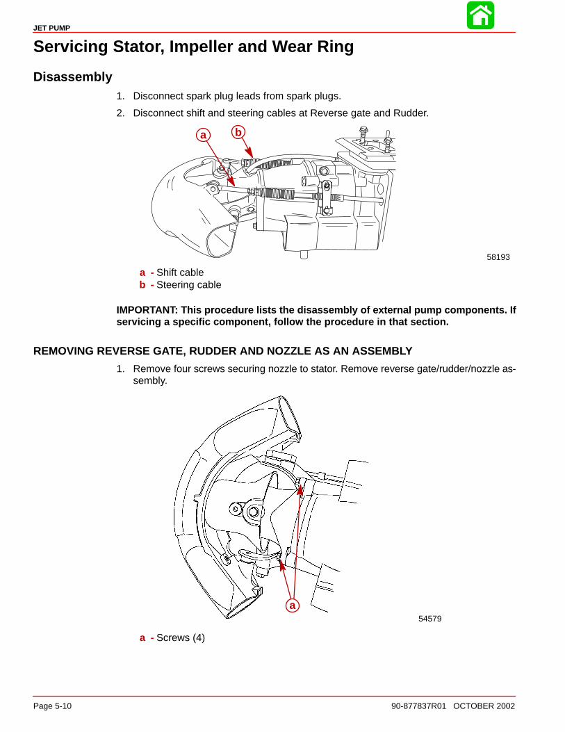
Disassembly1. Disconnect spark plug leads from spark plugs.
2. Disconnect shift and steering cables at Reverse gate and Rudder.
bb
58193
a
a - Shift cableb - Steering cable
IMPORTANT: This procedure lists the disassembly of external pump components. Ifservicing a specific component, follow the procedure in that section.
REMOVING REVERSE GATE, RUDDER AND NOZZLE AS AN ASSEMBLY
1. Remove four screws securing nozzle to stator. Remove reverse gate/rudder/nozzle as-sembly.
54579
a
a - Screws (4)

JET PUMP
90-877837R01 OCTOBER 2002 Page 5-11
STATOR REMOVAL
1. Remove two screws securing trim plate to ride plate and wear ring.
2. Remove four screws securing stator assembly to drive housing. Remove stator assem-bly.
2825358195
cab
a - Screws (2) to trim plate & wear ringb - Trim platec - Stator
3. Drain stator by tilting stator forward and allowing the oil to drain over the impeller shaftseals. Complete oil draining by removing stator fill plug and pour the remaining oil outthe fill plug hole.
IMPELLER REMOVAL
1. If removed, install wear ring to support impeller and shaft during impeller removal.
2. Remove inlet screen on bottom of drive housing to allow access to machined flats onimpeller shaft. Use Special Tool 91-832093A1 to hold impeller shaft for removing propel-ler nut.
3. While holding impeller shaft, remove impeller nut using Special Tool 91-850297. Impel-ler nut is a standard right hand thread. Remove impeller.
28252
a
b
a - Special Tool 91-850297b - Special Tool 91-832093A1
4. Remove wear ring.
JET PUMP
Page 5-12 90-877837R01 OCTOBER 2002
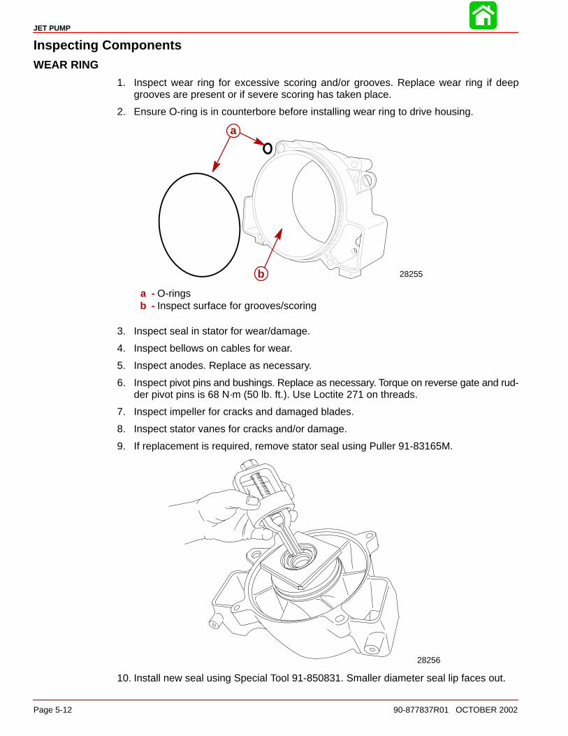
Inspecting ComponentsWEAR RING
1. Inspect wear ring for excessive scoring and/or grooves. Replace wear ring if deepgrooves are present or if severe scoring has taken place.
2. Ensure O-ring is in counterbore before installing wear ring to drive housing.
28255
a
b
a
b
a - O-ringsb - Inspect surface for grooves/scoring
3. Inspect seal in stator for wear/damage.
4. Inspect bellows on cables for wear.
5. Inspect anodes. Replace as necessary.
6. Inspect pivot pins and bushings. Replace as necessary. Torque on reverse gate and rud-der pivot pins is 68 N·m (50 lb. ft.). Use Loctite 271 on threads.
7. Inspect impeller for cracks and damaged blades.
8. Inspect stator vanes for cracks and/or damage.
9. If replacement is required, remove stator seal using Puller 91-83165M.
28256
10. Install new seal using Special Tool 91-850831. Smaller diameter seal lip faces out.

JET PUMP
90-877837R01 OCTOBER 2002 Page 5-13
IMPELLER
1. Place impeller in wear ring bore and push to one side.
2. Measure clearance between impeller blades and wear ring with a feeler gauge. If clear-ance is over 2.54 mm (0.100 in.), replace impeller and wear ring.
NOTE: Impeller wear usually accounts for 75% of the wear. Reducing the clearance canimprove both top speed and acceleration performance.
COMPONENT SPECIFICATIONS
Wear Ring Bore Diameter 184.73 - 184.98 mm (7.273 - 7.283 in.)
Impeller Outside Diameter 183.52 - 183.77 mm (7.225 - 7.235 in.)
Clearance between Impeller and Wear Ring 0.96 - 1.47 mm (0.038 - 0.058 in.)
3. Inspect leading edges of the impeller for nicks and damage. Leading edges should besharpened to 0.51 mm (0.020 in.) on the outer 1/2 of the leading edge for optimum per-formance. Dull leading edges can increase cavitation during initial acceleration.

JET PUMP
Page 5-14 90-877837R01 OCTOBER 2002
Installing Impeller1. Lubricate splines of impeller shaft with Special Lubricant 101.
2. Install impeller and nut on impeller shaft. Torque impeller nut to203 Nm (150 lb. ft.).
3. Install inlet screen. Apply Loctite 242 to threads of screws and bolts. Torque the two 6mm screws to 8.5 Nm (75 lb. in.). Torque the two 8 mm bolts to 22.5 Nm (200 lb. in.).
4. Install wear ring and stator. Apply Perfect Seal to threads of four bolts. Torque to 47 Nm(35 lb. ft.).
NOTE: Stator oil should be checked periodically for contamination and fluid level. To checkstator oil, shift reverse gate to the forward position. Using an allen socket and extension, re-move stator fill plug. Use a small screwdriver to dip into the oil to check for contamination,discoloration and level. If oil is low, add oil. If oil is contaminated or discolored, shaft, sealsand bushings must be inspected and/or replaced before refilling stator with new oil. After refil-ling stator with oil, apply Loctite PST Pipe Sealant to fill plug threads and reinstall plug.
5. Remove stator fill plug and fill stator with High Performance Gear Lube until oil flows outfill hole (capacity is 550 cc (19 fl. oz.). Install fill plug.
58196
a
a - Fill plug
6. Apply Loctite 242 to screws (2) securing trim plate to the ride plate. Torque screws to8.5 Nm (75 lb. in.).
58195ab
a - Screws (2) to trim plate & wear ringb - Trim plate
7. Install nozzle assembly and anode. Apply Loctite 271 to threads of screws. Torque allfour (4) screws to 47 Nm (35 lb. ft.).
8. Attach shift and steering cables.
NOTE: Refer to SECTION 1D - Sport Jet Installation for Shift and Steering Installation andAdjustment.

JET PUMP
90-877837R01 OCTOBER 2002 Page 5-15
Removing Jet Drive From Boat
NOTE: Remove powerhead as outlined in Section 4.
1. Disconnect shift and steering cables from reverse gate and rudder. Remove cable adap-tors and bellows assemblies. Loosen shift and steering cables at wear ring.
b
58193
a
a - Shift cableb - Steering cable
2. Loosen shift and steering cable thru-hull fittings.
3. Support pump.
28257
WARNINGThe pump unit must be supported to prevent it from dropping through the openingwhen the remaining fasteners are removed.
4. Remove remaining four nuts from drive housing cover. Remove drive housing cover andgasket.
a
a
b
58197
a - Nuts (4)b - Gasket
5. Lower drive housing while sliding cables out. Place on bench or suitable work stand fordisassembly/repair.
JET PUMP
Page 5-16 90-877837R01 OCTOBER 2002
Drive Housing Disassembly and Reassembly
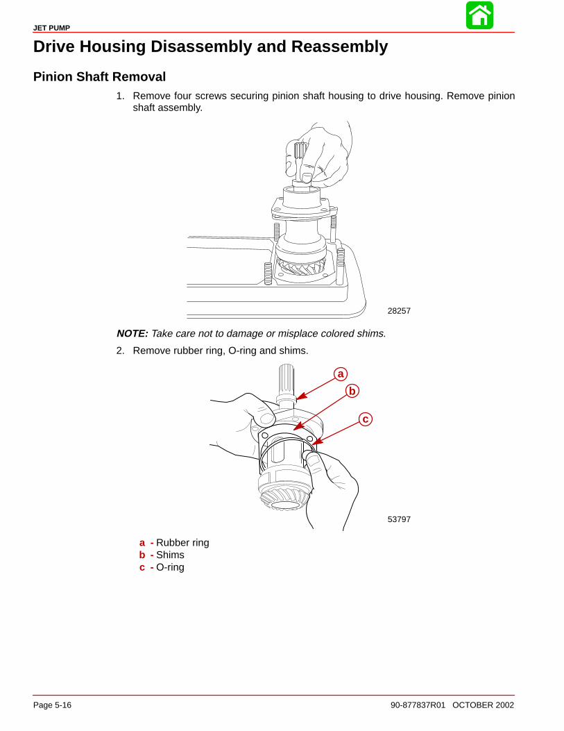
Pinion Shaft Removal1. Remove four screws securing pinion shaft housing to drive housing. Remove pinion
shaft assembly.
28257
NOTE: Take care not to damage or misplace colored shims.
2. Remove rubber ring, O-ring and shims.
53797
a
b
c
a - Rubber ringb - Shimsc - O-ring
JET PUMP
90-877837R01 OCTOBER 2002 Page 5-17
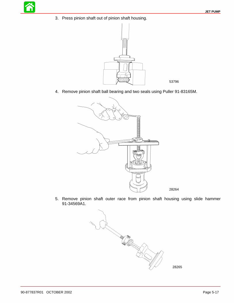
3. Press pinion shaft out of pinion shaft housing.
53796
4. Remove pinion shaft ball bearing and two seals using Puller 91-83165M.
28264
5. Remove pinion shaft outer race from pinion shaft housing using slide hammer91-34569A1.
28265
JET PUMP
Page 5-18 90-877837R01 OCTOBER 2002
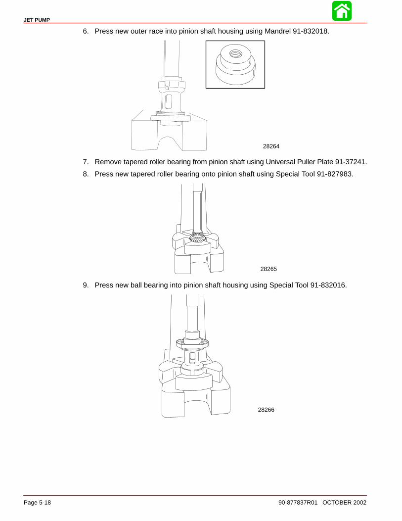
6. Press new outer race into pinion shaft housing using Mandrel 91-832018.
28264
7. Remove tapered roller bearing from pinion shaft using Universal Puller Plate 91-37241.
8. Press new tapered roller bearing onto pinion shaft using Special Tool 91-827983.
28265
9. Press new ball bearing into pinion shaft housing using Special Tool 91-832016.
28266

JET PUMP
90-877837R01 OCTOBER 2002 Page 5-19
10. Press pinion shaft into pinion housing.
28267
11. Press new seals into pinion shaft housing, one at a time, using Special Tool 91-820552.Inner seal faces in, outer seal faces out.
28268
a
a - Special Tool 91-820552
Impeller Shaft Removal1. Remove stator, wear ring and impeller as described in Servicing Impeller .
2. Remove stator fill screw, drain oil into a suitable container.
3. Remove ride plate.
4. Remove four screws securing impeller shaft cover to drive housing. Remove cover.
28257
JET PUMP
Page 5-20 90-877837R01 OCTOBER 2002
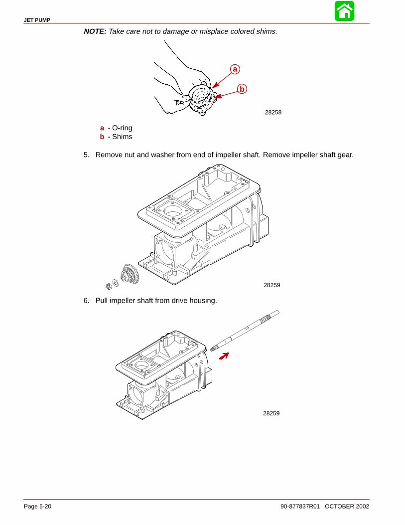
NOTE: Take care not to damage or misplace colored shims.
28258
a
b
a - O-ringb - Shims
5. Remove nut and washer from end of impeller shaft. Remove impeller shaft gear.
28259
6. Pull impeller shaft from drive housing.
28259
JET PUMP
90-877837R01 OCTOBER 2002 Page 5-21
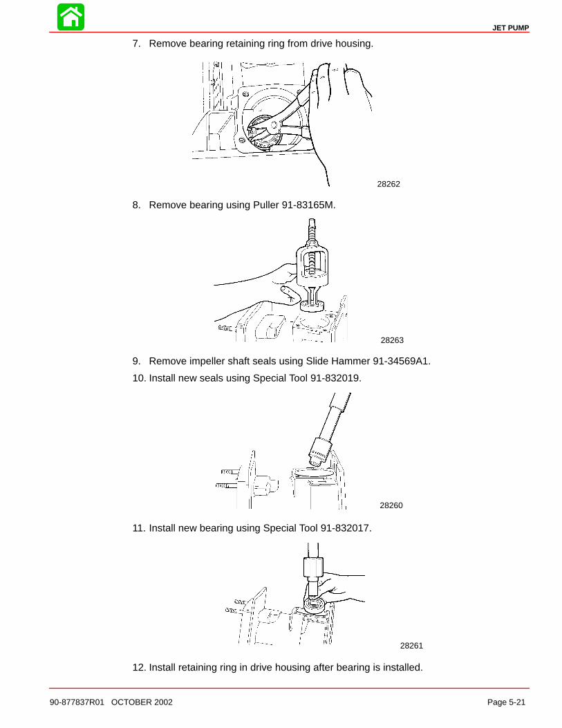
7. Remove bearing retaining ring from drive housing.
28262
8. Remove bearing using Puller 91-83165M.
28263
9. Remove impeller shaft seals using Slide Hammer 91-34569A1.
10. Install new seals using Special Tool 91-832019.
28260
11. Install new bearing using Special Tool 91-832017.
28261
12. Install retaining ring in drive housing after bearing is installed.

JET PUMP
Page 5-22 90-877837R01 OCTOBER 2002
13. If replacing impeller shaft gear bearing, remove using universal plate.
28269
a
b
a - Suitable mandrelb - Universal plate
14. Press new bearing on gear using an appropriate size mandrel.
28270
15. If replacing bearing, remove outer race from front cover using slide hammer. Press newouter race in cover using suitable mandrel.
54985
JET PUMP
90-877837R01 OCTOBER 2002 Page 5-23
Shimming ProceduresNOTE: Pinion gear shimming and backlash procedures must be preformed when any of thefollowing components have been replaced:
a. Jet drive housing
b. Pinion gear
c. Pinion gear bearing assembly
d. Pinion shaft housing
e. Impeller gear
f. Impeller gear bearing assembly
g. Impeller shaft front cover
NOTE: Shims are color coded to represent different thickness. These color codes apply toboth pinion housing shims and impeller cover shims.
Red 0.05 mm (0.002 in.)
Beige 0.10 mm (0.004 in.)
Blue 0.127 mm (0.005 in.)
Frost (Clear) 0.19 mm (0.0075 in.)
Brown 0.25 mm (0.010 in.)
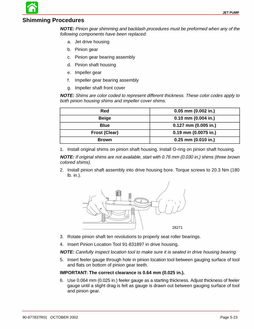
1. Install original shims on pinion shaft housing. Install O-ring on pinion shaft housing.
NOTE: If original shims are not available, start with 0.76 mm (0.030 in.) shims (three browncolored shims).
2. Install pinion shaft assembly into drive housing bore. Torque screws to 20.3 Nm (180lb. in.).
28271
3. Rotate pinion shaft ten revolutions to properly seat roller bearings.
4. Insert Pinion Location Tool 91-831897 in drive housing.
NOTE: Carefully inspect location tool to make sure it is seated in drive housing bearing.
5. Insert feeler gauge through hole in pinion location tool between gauging surface of tooland flats on bottom of pinion gear teeth.
IMPORTANT: The correct clearance is 0.64 mm (0.025 in.).
6. Use 0.064 mm (0.025 in.) feeler gauge as a starting thickness. Adjust thickness of feelergauge until a slight drag is felt as gauge is drawn out between gauging surface of tooland pinion gear.
JET PUMP
Page 5-24 90-877837R01 OCTOBER 2002
NOTE: Once the thickness is determined, the difference between feeler gauge thicknessand 0.64mm (0.025 in.) required clearance must be either added or subtracted from the totalthickness of shims between pinion shaft housing and drive housing.
• Remove the screws securing the pinion shaft housing assembly to the drive housing. Liftassembly out of the drive housing.
• Adjust shim thickness as required.
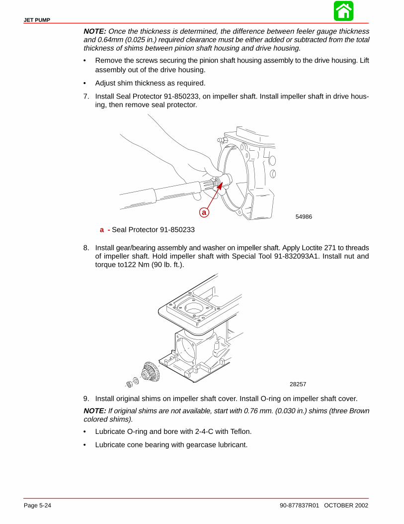
7. Install Seal Protector 91-850233, on impeller shaft. Install impeller shaft in drive hous-ing, then remove seal protector.
54986aa
a - Seal Protector 91-850233
8. Install gear/bearing assembly and washer on impeller shaft. Apply Loctite 271 to threadsof impeller shaft. Hold impeller shaft with Special Tool 91-832093A1. Install nut andtorque to122 Nm (90 lb. ft.).
28257
9. Install original shims on impeller shaft cover. Install O-ring on impeller shaft cover.
NOTE: If original shims are not available, start with 0.76 mm. (0.030 in.) shims (three Browncolored shims).
• Lubricate O-ring and bore with 2-4-C with Teflon.
• Lubricate cone bearing with gearcase lubricant.
JET PUMP
90-877837R01 OCTOBER 2002 Page 5-25
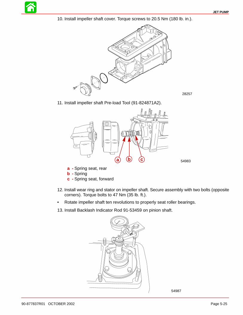
10. Install impeller shaft cover. Torque screws to 20.5 Nm (180 lb. in.).
28257
11. Install impeller shaft Pre-load Tool (91-824871A2).
54983a b c
a - Spring seat, rearb - Springc - Spring seat, forward
12. Install wear ring and stator on impeller shaft. Secure assembly with two bolts (oppositecorners). Torque bolts to 47 Nm (35 lb. ft.).
• Rotate impeller shaft ten revolutions to properly seat roller bearings.
13. Install Backlash Indicator Rod 91-53459 on pinion shaft.
54987
JET PUMP
Page 5-26 90-877837R01 OCTOBER 2002
14. Install Dial Indicator Kit, Adapter Kit and Thread Extender Kit.
• Position rod from dial indicator on the center mark II of the backlash indicator rod.
15. Rotate pinion shaft back and forth lightly to contact gear teeth in each direction.
NOTE: Average total amount of reading of indicator backlash specification is 0.18 mm(0.007 in.) to 0.23 mm (0.009 in.).
• If reading is less than minimum, add shims between impeller cover and drive housing.
• If reading is more than maximum, remove shims between impeller cover and drive housing.
• Ratio of backlash reading to shims is 1:1.
16. Install impeller, wear ring and stator as outlined in Installing Impeller in this section.
17. Apply RTV Sealant on rideplate. Install rideplate. Apply Loctite 242 to threads of screws.Torque to 8.5 Nm (75 lb. in.).
18. Install nozzle/reverse gate assembly and anode. Apply Loctite 271 to threads of screws.Torque all four (4) screws to 47 Nm (35 lb. ft.).
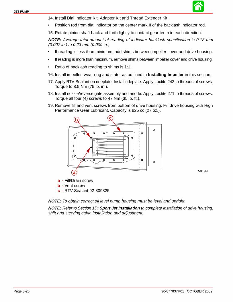
19. Remove fill and vent screws from bottom of drive housing. Fill drive housing with HighPerformance Gear Lubricant. Capacity is 825 cc (27 oz.).
58199
cb
a
a - Fill/Drain screwb - Vent screwc - RTV Sealant 92-809825
NOTE: To obtain correct oil level pump housing must be level and upright.
NOTE: Refer to Section 1D: Sport Jet Installation to complete installation of drive housing,shift and steering cable installation and adjustment.