Embed Size (px)
Citation preview
11 A-I
ENGINE CONTENTS 111 09O00313
ENGINE <1.5L> ........................................... 11A
ENGINE OVERHAUL <1.5L> ................................ 11B
ENGINE <1.8L> ........................................... 11C
ENGINE OVERHAUL <1.8L> ................................ 11D
11 A-2
ENGINE <I . 5L> CONTENTS 11109000726
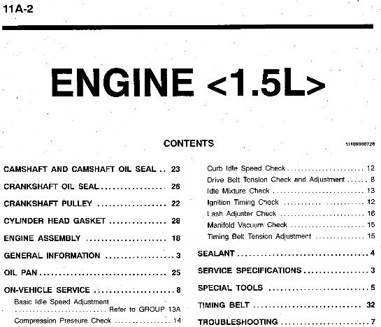
CAMSHAFT AND CAMSHAFT OIL SEAL .. 23
CRANKSHAFT OIL SEAL 26
Curb Idle Speed Check . . . . . . . . . . . . . . . . . . . . . . 12
Drive Belt Tension Check and Adjustment . . . . . . 8
Idle Mixture Check 13 ................. . . . . . . . . . . . . . . . . . . . . . . . . . . CRANKSHAFT PULLEY .................. 22 Ignition Timing Check . . . . . . . . . . . . . . . . . . . . . . . 12
Lash Adjuster Check . . . . . . . . . . . . . . . . . . . . . . . . 16 ............... Manifold Vacuum Check 15 CYLINDER HEAD GASKET 28 . . . . . . . . . . . . . . . . . . . . . Timing Belt Tension Adjustment . . . . . . . . . . . . . . 15 ENGINE ASSEMBLY ..................... 18
.................. .................................. GENERAL INFORMATION 3 SEALANT 4
OIL PAN ................................. 25 SERVICE SPEClFlCATlONS ................. 3
TIMING BELT 32
TROUBLESHOOT~NG ........................ 7
Basic Idle Speed Adjustment . . . . . . . . . . . . . . . . . . . . . . . . . . Refer to GROUP 13A
Compression Pressure Check . . . . . . . . . . . . . . . . 14
............................
ENGINE c1.5L> - General Information/Service Specifications 11 A-3
Items
TY Pe
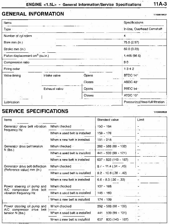
GENERAL IN FORMATION Specifications
In-line, Overhead Camshaft
11 1 0001 0537
Piston displacement cm3 ( c u h )
Compression ratio
Firing order
1,468 (86.6)
9.0
1-3-4-2
Number of cylinders
Bore mm (in.) __ - _ _ _
Valve timing
I 4
Intake valve Opens BTDC 14"
Closes ABDC 48"
Exhaust valve Opens BBDC 54"
Closes ATDC 10"
~ 75.5 (2.97)
Generator drive belt vibration frequency Hz
When checked
When a used belt is installed 159 - 176 -
When a new belt is installed -
1 150 - 184
191 - 21 8
Generator drive belt tension N (Ibs.)
Lubrication I Pressurized feed-full filtration
I - When checked
When a used belt is installed
1 392 - 588 (88 - 132)
441 - 539 (99 - 121) -
SERVICE SPECIFICATIONS 11100030625
b h e n a new belt is installed
~ I Items 1 Standard value 1 Limit
637 - 833 (143 - 187) -
Generator drive belt deflection (Reference value) mm (in.)
I
When checked 8.7 - 11.4 (-34 - .45)
When a used belt is installed
When a new belt is installed
9.2 - 10.6 (.36 - -42)
6.6 - 8.3 (.26 - .33)
-
-
When a new belt is installed
When checked
Power steering oil pump and A/C compressor drive belt vibration frequency Hz
174 - 199
392 - 588 (88 - 132) Power steering oil pump and A/C compressor drive belt tension N (Ibs.)
I When checked I 137 - 168 l - I When a used belt is installed 1 145 - 160 I -
~ When a used belt is installed I 441 - 539 (99 - 121) I -
1 When a new belt is installed I 637 - 833 (143 - 187) I -
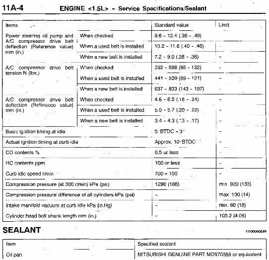
1 1 A-4 ENGINE 4.5L> - Service Specifications/Sealant
Items .- Standard value
A/C compressor drive belt deflection (Reference value) When a used belt is installed 10.2 - 11.6 (.40 - .46) mm (in.)
Power steering oil pump and When checked 9.6 - 12.4 (.38 - .49)
When a new belt is installed 7.2 - 9.0 (.28 - .36)
Limit
-
-
-
A/C compressor drive belt tension N (Ibs.)
A/C compressor drive belt deflection (Reference value) mm (in.)
Basic ignition timing at idle 1 5 " B T D C ~ 3 " I -
When checked 392 - 588 (88 - 132) - When a used belt is installed
When a new belt is installed
441 - 539 (99 - 121)
637 - 833 (1 43 - 187)
- -
When checked 4.6 - 6.2 (.18 - .24) - When a used belt is installed
When a new belt is installed
5.0 - 5.7 (.20 - .22)
3.4 - 4.3 (.13 - -17)
-
Actual ignition timing at curb idle I Approx. 10"BTDC I -
~~ ~~ ~ ~
Compression pressure difference of all cylinders kPa (psi)
Intake manifold vacuum at curb idle kPa (in.Hg)
Cylinder head bolt shank length mm (in.)
CO contents % 1 0.5 or less I -
- i m a . lOO(14)
- min. 60 (18)
- 103.2 (4.06)
HC contents ppm I 100 or less l - Curb idle speed r/min
Compression pressure (at 300 r/min) kPa (psi)
! 7002 100 l - ~ 1290(188) 1 min. 920 (133)
SEALANT 111 OO050249
I item I Specified sealant I I oil pan i MlTSUBlSHl GENUINE PART MD970389 or equivalent 1
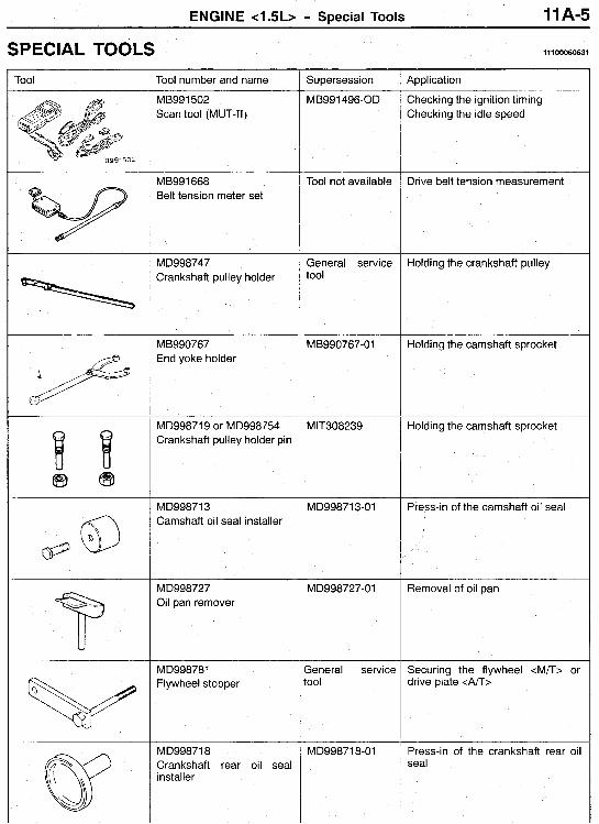
ENGINE c1.5L> - Special Tools 11 A-5
SPECIAL TOOLS 11100060631
Tool number and name Supersession Application I Tool
ME3991 502 Scan tool (MUT-11)
MB991496-OD Checking the ignition timing Checking the idle speed
MB991668 Belt tension meter set
Tool not available Drive belt tension measurement
MD998747 Crankshaft pulley holder
Holding the crankshaft pulley General service tool
MB990767 End yoke holder
MB990767-01 Holding the camshaft sprocket
MD998719 or MD998754 Crankshaft pulley holder pin
MlT308239 Holding the camshaft sprocket
MD998713 Camshaft oil seal installer
MD998713-01 Press-in of the camshaft oil seal I
MD998727 Oil pan remover
MD998727-01 Removal of oil pan
MD998781 Flywheel stopper
Seneral service tool
Securing the flywheel <M/T> drive plate <An>
MD998718 Crankshaft rear oil seal installer
MD998718-01 Press-in of the crankshaft rear seal
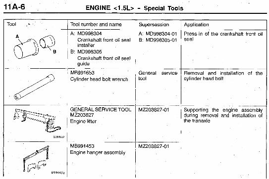
11 A-6 ENGINE c1.5L> - SDecial Tools
Tool .*
2203827
Tool number and name
A: MD998304 Crankshaft front oil seal installer
B: MD998305 Crankshaft front oil seal guide
MB991653 Cylinder head bolt wrench
GENERAL SERVICETOOL MZ203827 Engine lifter
MB991453 Engine hanger assembly
Supersession ~~~
A: MD998304-01 B: MD998305-01
General service tool
MZ203827-01
MZ203827-01
Application
Press-in of the crankshaft front oil seal
Removal and installation of the cylinder head bolt
Supporting the engine assembly during removal and installation of the tranaxle
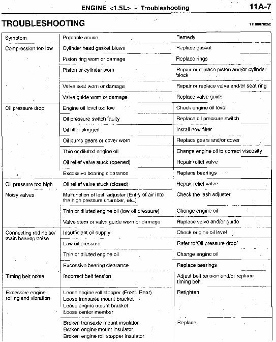
ENGINE <I .5L> - Troubleshooting 1 1 A-7
TROUBLESHOOTING 11100070252
3emedy I Symptom Probable cause
Cylinder head gasket blown 3eplace gasket Compression too low
Piston ring worn or damage 3eplace rings
3epair or replace piston and/or cylinder slock
Piston or cylinder worn
Valve seat worn or damage 3epair or replace valve and/or seat ring
qeplace valve guide
Sheck engine oil level
Replace oil pressure switch
Valve guide worn or damage
Oil pressure drop Engine oil level too low
Oil pressure switch faulty
Oil filter clogged Install new filter ~
Oil pump gears or cover worn
Thin or diluted engine oil
Oil relief valve stuck (opened)
Replace gears and/or cover
Change engine oil to correct viscosity
Repair relief valve
Replace bearings
Repair relief valve
Excessive bearing clearance t Oil pressure too high Oil relief valve stuck (closed)
Check the lash adjuster Malfunction of lash adjuster (Entry of air into the high pressure chamber, etc.)
Thin or diluted engine oil (low oil pressure)
Noisy valves
Change engine oil
Replace valve and/or guide
Check engine oil level .
Refer to"0il pressure drop"
Valve stem or valve guide worn or damage
Connecting rod noise/ main bearing noise
Insufficient oil supply
Low oil pressure
Thin or diluted engine oil Change engine oil ~
Excessive bearing clearance
Incorrect belt tension
Replace bearings
Adjust belt tension and/or replace timing belt
Timing belt noise
Excessive engine rolling and vibration
Retighten Loose engine roll stopper (Front, Rear) Loose transaxle mount bracket Loose engine mount bracket Loose center member
Broken transaxle mount insulator Broken engine mount insulator Broken engine roll stopper insulator
Replace
11 A-8 ENGINE <I .5L> - On-vehicle Service
~~
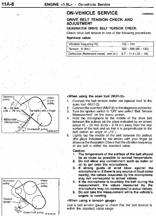
x b ra t i on frequency Hz _ _ -~
Tension N (Ibs.)
Deflection (Reference value) mm (in.)
e -
150 - 184
392 - 588 (88 - 132) ~~
8.7 - 11.4 (.34 - .45)
ON-VEHICLE SERVICE 11100090562
DRIVE BELT TENSION CHECK AND ADJUSTMENT GENERATOR DRIVE BELT TENSION CHECK Check drive belt tension in one of the following procedures. Standard value:
<When using the scan tool (MUT-11)s 1.
2. 3.
4.
5.
Connect the belt tension meter set (special tool) to the scan tool (MUT-11). Connect the scan tool (MUT-11) to the diagnosis connector. Turn the ignition switch to “ON” and select “Belt Tension Measurement” on the menu screen. Hold the microphone to the middle of the drive belt between the pulleys (at the place indicated by an arrow) about 10 - 20 mm (0.39 - 0.79 in.) away from the rear surface of the belt and so that it is perpendicular to the belt (within an angle of 215”). Lightly tap the middle of the belt between the pulleys (the place indicated by the arrow) with your finger as shown in the illustration. Check that the vibration frequency of the belt is within the standard value. Caution 1. The temperature of the surface of the belt should
be as close as possible to normal temperature. 2. Do not allow any contaminant such as water or
oil to get onto the microphone. 3. If strong gusts of wind blow against the
microphone or if there is any source of loud noise nearby, the values measured by the microphone may not correspond to actual values.
4. If the microphone is touching the belt during the measurement, the values measured by the microphone may not correspond to actual values.
5. Do not take the measurement while the vehicle’s engine is running.
<When using a tension gauge> Use a belt tension gauge to check that the belt tension is within the standard value range.
ENGINE <I .5L> - On-vehicle Service 11 A-9
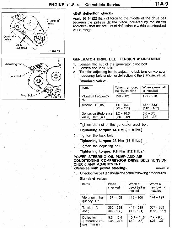
<Belt deflection check> Apply 98 N (22 Ibs.) of force to the middle of the drive belt between the pulleys (at the place indicated by the arrow) and check that the amount of deflection is within the standard value range.
When a used belt is installed
(22 Ibs.) v- 1 E N 0 4 2 9
When a new belt is installed
GENERATOR DRIVE BELT TENSION ADJUSTMENT 1. Loosen the nut of the generator pivot bolt. 2. Loosen the lock bolt. 3. Turn the adjusting bolt to adjust the belt tension vibration
frequency, belt tension or deflection to the standard value.
Deflection (Reference val- ue) mm (in.)
Standard value:
9.6 - 12.4 (.38 - .49)
Items
Vibration frequency Hz
Tension N (Ibs.)
Deflection (Reference value) mm (in.)
4. Tighten the nut of the generator pivot bolt. Tightening torque: 44 Nm (33 ft.lbs.)
5. Tighten the lock bolt. Tightening torque: 23 Nm (17 ft.lbs.)
6. lighten the adjusting bolt. Tightening torque: 9.8 Nm (7.2 ft.lbs.)
POWER STEERING OIL PUMP AND AIR CONDITIONING COMPRESSOR DRIVE BELT TENSION CHECK AND ADJUSTMENT
1. Check drive belt tension in one of the following procedures. Standard value:
<Vehicles with power steering> 111 001 301 96
Items When a used belt is intalled
Vibration fre- ~ 137 - 168 quency Hz
Tension N 392 - 588 (Ibs.) (88 - 132)
145 - 160
441 - 539 (99 - 121)
10.2 - 11.6 (.40 - .46)
When a new belt is installed
174 - 199
637 - 833 (143 - 187)
7.2 - 9.0 (.28 - .35)
11A-10 ENGINE <1.5L> - On-vehicle Service
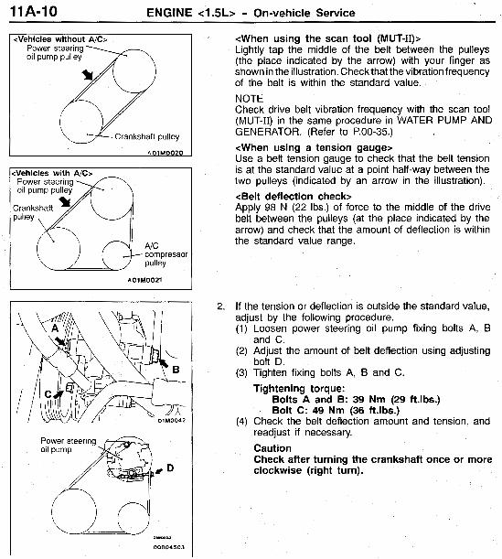
<Ve hicles without AlC> Power steering oil pump pulley
Crankshaft pulley
A01M0020
compressor pulley
A01M0021
m m a a
00004503
<When using the scan tool (MUT-II)> Lightly tap the middle of the belt between the pulleys (the place indicated by the arrow) with your finger as shown in the illustration. Check that the vibration frequency of the belt is within the standard value. NOTE Check drive belt vibration frequency with the scan tool (MUT-11) in the same procedure in WATER PUMP AND GENERATOR. (Refer to P.00-35.) <When using a tension gauge> Use a belt tension gauge to check that the belt tension is at the standard value at a point half-way between the two pulleys (indicated by an arrow in the illustration). <Belt deflection check> Apply 98 N (22 Ibs.) of force to the middle of the drive belt between the pulleys (at the place indicated by the arrow) and check that the amount of deflection is within the standard value range.
2. If the tension or deflection is outside the standard value, adjust by the following procedure. (1) Loosen power steering oil pump fixing bolts A, B
(2) Adjust the amount of belt deflection using adjusting
(3) Tighten fixing bolts A, B and C.
and C.
bolt D.
Tightening torque: Bolts A and B: 39 Nm (29 ft.lbs.) Bolt C: 49 Nm (36 ft.lbs.)
(4) Check the belt deflection amount and tension, and readjust if necessary. Caution Check after turning the crankshaft once or more clockwise (right turn).
ENGINE <I .5L> - On-vehicle Service 11A-11
When a used belt is intalled
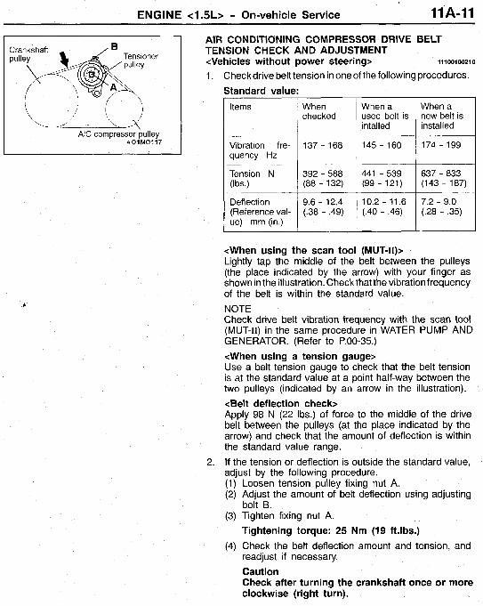
NC compressor pulley A01M0117
When a new belt is installed
AIR CONDITIONING COMPRESSOR DRIVE BELT TENSION CHECK AND ADJUSTMENT
1 . Check drive belt tension in one of the following procedures. Standard value:
<Vehicles without power steering> 111 00100210
Items
Vibration fre- quency Hz
Tension N (Ibs.)
Deflection (Reference val- ue) mm (in.)
When checked
137 - 168
392 - 588 (88 - 132)
9.6 - 12.4 (.38 - -49)
145 - 160 I 174 - 199
<When using the scan tool (MUT-II)> Lightly tap the middle of the belt between the pulleys (the place indicated by the arrow) with your finger as shown in the illustration. Check that the vibration frequency of the belt is within the standard value. NOTE Check drive belt vibration frequency with the scan tool (MUT-11) in the same procedure in WATER PUMP AND GENERATOR. (Refer to P.00-35.) <When using a tension gauge> Use a belt tension gauge to check that the belt tension is at the standard value at a point half-way between the two pulleys (indicated by an arrow in the illustration). <Belt deflection check> Apply 98 N (22 Ibs.) of force to the middle of the drive belt between the pulleys (at the place indicated by the arrow) and check that the amount of deflection is within the standard value range.
2. If the tension or deflection is outside the standard value, adjust by the following procedure. (1) Loosen tension pulley fixing nut A. (2) Adjust the amount of belt deflection using adjusting
(3) Tighten fixing nut A.
(4) Check the belt deflection amount and tension, and
bolt B.
Tightening torque: 25 Nm (19 ft.lbs.)
readjust if necessary. Caution Check after turning the crankshaft once or more clockwise (right turn).
11A-12 ENGINE e l .5L> - On-vehicle Service
1.
2. 3. 4. 5. 6.
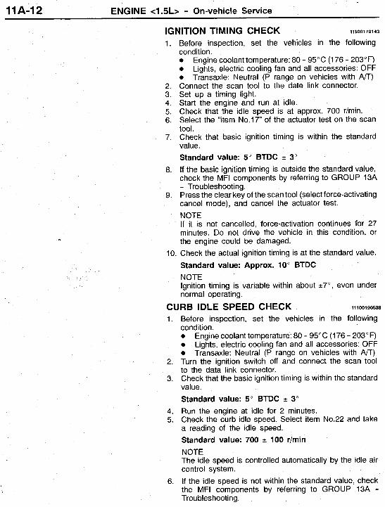
IGNITION TIMING CHECK 11100170143
7.
8.
9.
c
10.
Before inspection, set the vehicles in the following condition. 0 Engine coolant temperature: 80 - 95°C (1 76 - 203°F) 0 Lights, electric cooling fan and all accessories: OFF 0 Transaxle: Neutral (P range on vehicles with A/T) Connect the scan tool to the date link connector. Set up a timing light. Start the engine and run at idle. Check that the idle speed is at approx. 700 r/min. Select the "item No.17" of the actuator test on the scan tool. Check that basic ignition timing is within the standard value . Standard value: 5" BTDC -c 3"
If the basic ignition timing is outside the standard value, check the MFI components by referring to GROUP 13A - Troubleshooting. Press the clear key of the scan tool (select force-activating cancel mode), and cancel the actuator test. NOTE If it is not cancelled, force-activation continues for 27 minutes. Do not drive the vehicle in this condition, or the engine could be damaged. Check the actual ignition timing is at the standard value. Standard value: Approx. 10" BTDC NOTE Ignition timing is variable within about 27", even under normal operating.
CURB IDLE SPEED CHECK 11 1001 90538
4. 5.
6.
Before inspection, set the vehicles in the following condition. 0 Engine coolant temperature: 80 - 95°C (1 76 - 203" F) 0 Lights, electric cooling fan and all accessories: OFF 0 Transaxle: Neutral (P range on vehicles with A/T) Turn the ignition switch off and connect the scan tool to the data link connector. Check that the basic ignition timing is within the standard value. Standard value: 5" BTDC f 3" Run the engine at idle for 2 minutes. Check the curb idle speed. Select item No.22 and take a reading of the idle speed. Standard value: 700 100 r/min NOTE The idle speed is controlled automatically by the idle air control system. If the idle speed is not within the standard value, check the MFI components by referring to GROUP 13A - Troubleshooting.
ENGINE c1.5L> - On-vehicle Service 11A-13
u IDLE MIXTURE CHECK 11100210241
1.
2.
3.
4. 5. 6.
7.
Before inspection, set the vehicles in the following condition. 0 Engine coolant temperature: 80 - 95°C (176 - 203°F) 0 Lights, electric cooling fan and all accessories: OFF 0 Transaxle: Neutral (P range on vehicles with An) Turn the ignition switch off and connect the scan tool to the data link connector. Check that the basic ignition timing is within the standard value. Standard value: 5"BTDC -c 3" Run the engine at 2,500 r/min for 2 minutes. Set the CO/HC tester. Check the CO contents and the HC contents at idle. Standard value:
CO contents: 0.5% or less HC contents: 100 ppm or less
If the idle speed is not within the standard value, check the following items: 0 Diagnostic output 0 Closed-loop control (When the closed-loop control
is carried out normally, the output signal of the heated oxygen sensor repeats between 0 - 400 mV and 600 - 1,000 mV at idle.)
Ignition coil, spark plug cable, spark plug EGR system and the EGR valve leak
0 Fuel pressure 0 Injector 0
0
0 Evaporative emission control system 0 Compression pressure NOTE Replace the three-way catalyst whenever the CO and HC contents do not remain inside the standard value. (even though the result of the inspection is normal on all items).
11A-14 ENGINE c1.5L> - On-vehicle Service
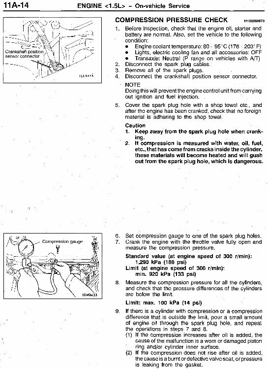
COM P R ESSl ON P R ESSU RE CH ECK 111 00260673
1.
2. 3. 4.
5.
6. 7.
8.
9.
Before inspection, check that the engine oil, starter and battery are normal. Also, set the vehicle to the following condition: 0 Engine coolant temperature: 80 - 95°C (176 - 203°F) 0 Lights, electric cooling fan and all accessories: OFF 0 Transaxle: Neutral (P range on vehicles with A/T) Disconnect the spark plug cables. Remove all of the spark plugs. Disconnect the crankshaft position sensor connector. NOTE Doing this will prevent the engine control unit from carrying out ignition and fuel injection. Cover the spark plug hole with a shop towel etc., and after the engine has been cranked, check that no foreign material is adhering to the shop towel. Caution 1. Keep away from the spark plug hole when crank-
ing. 2. If compression is measured with water, oil, fuel,
etc., that has come from cracks inside the cylinder, these materials will become heated and will gush out from the spark plug hole, which is dangerous.
Set compression gauge to one of the spark plug holes. Crank the engine with the throttle valve fully open and measure the compression pressure. Standard value (at engine speed of 300 r/min):
Limit (at engine speed of 300 r/min):
Measure the compression pressure for all the cylinders, and check that the pressure differences of the cylinders are below the limit.
1,290 kPa (188 psi)
min. 920 kPa (133 psi)
Limit: max. 100 kPa (14 psi) If there is a cylinder with compression or a compression difference that is outside the limit, pour a small amount of engine oil through the spark plug hole, and repeat the operations in steps 7 and 8. (1) If the compression increases after oil is added, the
cause of the malfunction is a worn or damaged piston ring and/or cylinder inner surface.
(2) If the compression does not rise after oil is added, the cause is a burnt or defective valve seat, or pressure is leaking from the gasket.
ENGINE <1.5L> - On-vehicle Service 11A-15
Va
1EN0434
.35
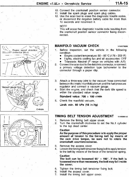
10. Connect the crankshaft position sensor connector. 11. Install the spark plugs and spark plug cables. 12. Use the scan tool to erase the diagnostic trouble codes,
or disconnect the negative battery cable for more than 10 seconds and reconnect it. NOTE This will erase the diagnostic trouble code resulting from the crankshaft position sensor connector being discon- nected.
1.
2.
3.
4.
5.
Before inspection, set the vehicle in the following condition. 0 Engine coolant temperature: 80 - 95°C (176 - 203°F) 0 Lights, electric cooling fan and all accessories: OFF 0 Transaxle: Neutral (P range on vehicles with A/T) Connect the scan tool to the data link connector, or connect a primary voltage detection type tachometer to the connector through a paper clip.
Attach a three-way joint to the vacuum hose connected between the intake manifold plenum and the fuel pressure regulator and connect a vacuum gauge. Start the engine, and check that the curb idle speed is within the standard value range. Standard value: 700 e 100 r/min Check the manifold vacuum. Limit: min. 60 kPa (18 in.Hg)
MANIFOLD VACUUM CHECK 111 00270256
TIMING BELT TENSION ADJUSTMENT I I I O O ~ ~ O I I ~
1. 2.
3. 4.
5. 6. 7.
Remove the timing belt upper cover. Turn the crankshaft clockwise to set the No.1 cylinder to the top dead center. Caution As the purpose of this procedure is to apply the proper amount of tension to the timing belt by means of the cam drive torque, be sure not to rotate the crankshaft counterclockwise. Remove the access cover. Loosen the timing belt tensionerfixing bolt to apply tension to the belt by means of the force of the tensioner spring. Caution The bolt can be loosened 90" - 180". If the belt is loosened more than necessary, the bolt may fall inside the cover. Tighten the timing belt tensioner fixing bolt. Install the access cover. Install the timing belt upper cover.
11A-16 ENGINE c1.5L> - On-vehicle Service
LASH ADJUSTER CHECK 11100290665
If an abnormal noise (clicking) assumed to be caused by a fault in the lash adjuster is heard and does not stop after the engine is started, inspect the following items. NOTE
1. 2.
3.
4.
5.
6.
The abnormal noise caused by the lash adjuster occurs just after starting and fluctuates according to the engine speed, but is not related to the engine load. Thus, if the abnormal noise does not occur just after the engine speed, if it does not fluctuate according to the engine speed, or if it fluctuates according to the engine load, the lash adjuster is not the cause of the abnormal noise. If the lash adjuster is defective, often the abnormal noise will not stop even if warmup operation is continued in the idling state. Note that the abnormal noise may stop only if the noise is caused by fixing of oil sludge in an engine where the oil control is poor. Start the engine. Check whether the abnormal noise starts immediately after starting, and whether it fluctuates according to the engine speed when the engine speed is varied. If the abnormal noise does not occur immediately after starting, or if it does not fluctuate according to the engine speed, the cause is not with the lash adjuster, so investigate for other causes of the abnormal noise. If the abnormal noise does not fluctuate according to the engine speed, it is assumed that the cause is not the engine unit. (In this case, the lash adjuster is normal.) Check whether the abnormal noise level does not change when the engine load is fluctuated (ex., shift from N to D range) in the idling state. If the abnormal noise level fluctuates, this may be a hitting sound caused by wear of the crankshaft bearings or connecting rod bearings. (In this case, the lash adjuster is normal.) Check for abnormal noise in the idling state after warmup operation is completed. If the abnormal noise is quieter or has stopped, it is assumed that the noise was caused by fixing of the lash adjuster due to oil sludge, etc., so wash the lash adjuster. (Refer to GROUP 116 - Rocker Arms and Camshaft.) If the abnormal noise level does not fluctuate, go to step 5. Bleed the air from the lash adjuster. (Refer to GROUP 11 A-1 7.) If the abnormal noise does not stop even after purging the air, wash the lash adjuster. (Refer to GROUP 11B - Rocker Arms and Camshaft.)
ENGINE <I .5L> - On-vehicle Service 11A-17
01L0183
High- pressure chamber
w 7EN0392
Air bleeding operation pattern
Gradually open the throttle valve Approx. Close the throttle valve
7FU2059
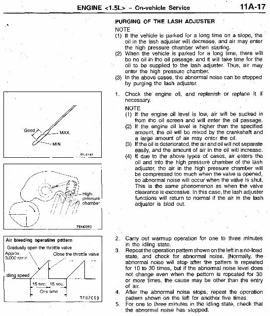
PURGING OF THE LASH ADJUSTER NOTE
If the vehicle is parked for a long time on a slope, the oil in the lash adjuster will decrease, and air may enter the high pressure chamber when starting. When the vehicle is parked for a long time, there will be no oil in the oil passage, and it will take time for the oil to be supplied to the lash adjuster. Thus, air may enter the high pressure chamber. In the above cases, the abnormal noise can be stopped by purging the lash adjuster.
Check the engine oil, and replenish or replace it if necessary. NOTE (1) If the engine oil level is low, air will be sucked in
from the oil screen and will enter the oil passage. (2) If the engine oil level is higher than the specified
amount, the oil will be mixed by the crankshaft and a large amount of air may enter the oil.
(3) If the oil is deteriorated, the air and oil will not separate easily, and the amount of air in the oil will increase.
(4) If due to the above types of cases, air enters the oil and into the high pressure chamber of the lash adjuster, the air in the high pressure chamber will be compressed too much when the valve is opened, so abnormal noise will occur when the valve is shut. This is the same phenomenon as when the valve clearance is excessive. In this case, the lash adjuster functions will return to normal if the air in the lash adjuster is bled out.
Carry out warmup operation for one to three minutes in the idling state. Repeat the operation pattern shown on the left in a no-load state, and check for abnormal noise. (Normally, the abnormal noise will stop after the pattern is repeated for 10 to 30 times, but if the abnormal noise level does not change even when the pattern is repeated for 30 or more times, the cause may be other than the entry of air. After the abnormal noise stops, repeat the operation pattern shown on the left for another five times. For one to three minutes in the idling state, check that the abnormal noise has stopped.
11A-18 ENGINE <1.5L> - Engine Assembly
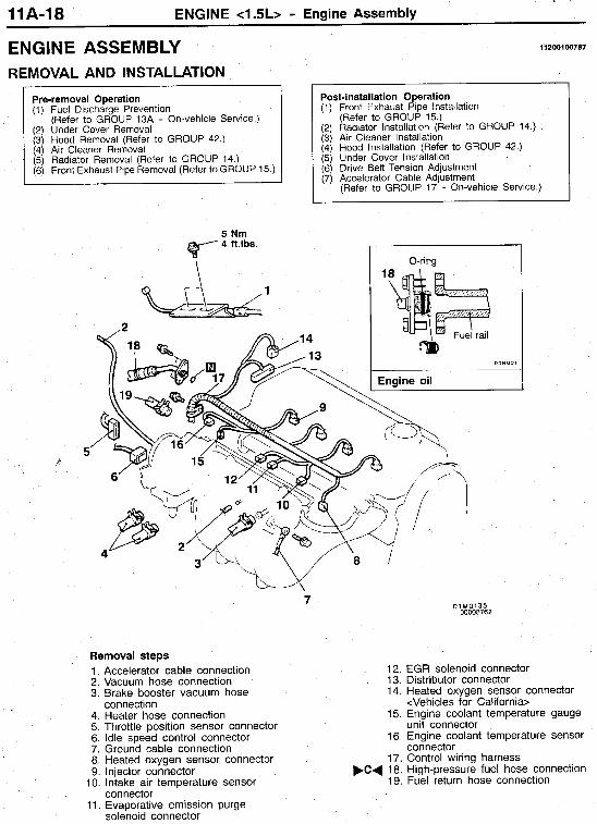
(1) Fuel Discharge Prevention (Refer to GROUP 13A - On-vehicle Service.)
(2) Under Cover Removal (3) Hood Removal (Refer to GROUP 42.) (4) Air Cleaner Removal (5) Radiator Removal (Refer to GROUP 14.) (6) Front Exhaust Pipe Removal (Refer to GROUP 15.)
11200100787 ENGINE ASSEMBLY
Post-installation Operation (1) Front Exhaust Pipe Installation
(Refer to GROUP 15.) (2) Radiator Installation (Refer to GROUP 14.) (3) Air Cleaner Installation (4) Hood Installation (Refer to GROUP 42.) (5) Under Cover Installation (6) Drive Belt Tension Adjustment (7) Accelerator Cable Adjustment
(Refer to GROUP 17 - On-vehicle Service.)
O-ring 1
03N00
Engine oil
1. Accelerator cable connection 2. Vacuum hose connection 3. Brake booster vacuum hose
4. Heater hose connection 5. Throttle position sensor connector 6. Idle speed control connector 7. Ground cable connection 8. Heated oxygen sensor connector 9. injector connector
10. Intake air temperature sensor
11. Evaporative emission purge
connection
connector
solenoid connector
12. EGR solenoid connector 13. Distributor connector 14. Heated oxygen sensor connector
<Vehicles for California> 15. Engine coolant temperature gauge
unit connector 16. Engine coolant temperature sensor
connector 17. Control wiring harness
F C d 18. High-pressure fuel hose connection 19. Fuel return hose connection
ENGINE c1.5L> - Engine Assembly 11A-19
Nm ft.lbs.
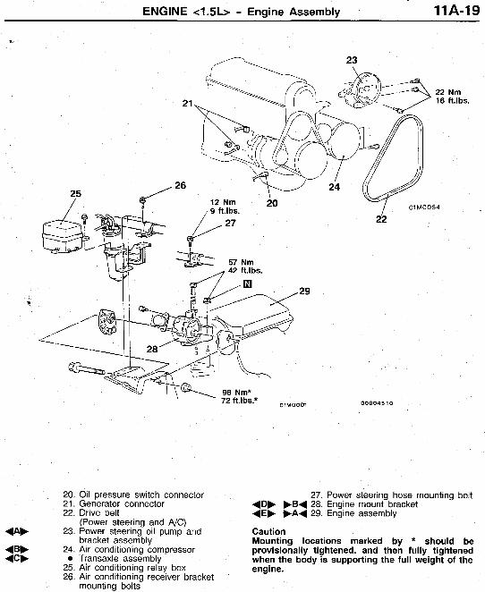
20. 21. 22.
4- 23.
4 B b 24.
25. 26.
0 4 C b
72 ft.lbs.* OIMOOOl 00004510
Oil pressure switch connector Generator connector Drive belt (Power steering and A/C) Power steering oil pump and bracket assembly Air conditioning compressor Transaxle assembly Air conditioning relay box Air conditioning receiver bracket mounting bolts
27. Power steering hose mounting bolt 4 D b b B 4 28. Engine mount bracket 4 E b F A 4 29. Engine assembly
Caution Mounting locations marked by * should be provisionally tightened, and then fully tightened when the body is supporting the full weight of the engine.
11 A-20 ENGINE c1.5L> - Engine Assembly
e
M/T
Flywheel
MZ203827 = \ n
I 1
I \ A01M0002
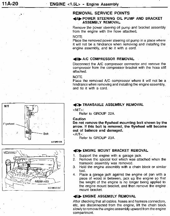
REMOVAL SERVICE POINTS +A,POWER STEERING OIL PUMP AND BRACKET
ASSEMBLY REMOVAL Remove the power steering oil pump and bracket assembly from the engine with the hose attached. NOTE Place the removed power steering oil pump in a place where it will not be a hindrance when removing and installing the engine assembly, and tie it with a cord.
(BF A/C COMPRESSOR REMOVAL Disconnect the A/C compressor connector and remove the compressor from the compressor bracket with the hose still attached.
NOTE Place the removed A/C compressor where it will not be a hindrance when removing and installing the engine assembly, and tie it with a cord.
(CF TRANSAXLE ASSEMBLY REMOVAL <M/T>:
Caution Do not remove the flywheel mounting bolt shown by the arrow. If this bolt is removed, the flywheel will become out of balance and damaged. <A/T>:
Refer to GROUP 23A.
Refer to GROUP 22A.
+D, ENGINE MOUNT BRACKET REMOVAL 1. Support the engine with a garage jack. 2. Remove the special tool which was attached when the
transaxle assembly was removed. 3. Hold the engine assembly with a chain block or similar
tool. 4. Place a garage jack against the engine oil pan with a
piece of wood in between, jack up the engine so that the weight of the engine is no longer being applied to the engine mount bracket, and then remove the engine mount bracket.
(E, ENGINE ASSEMBLY REMOVAL After checking that all cables, hoses and harness connectors, etc, are disconnected from the engine, lift the chain block slowly to remove the engine assembly upward from the engine compartment.
ENGINE c1.5L> - Engine Assembly 11 A-21
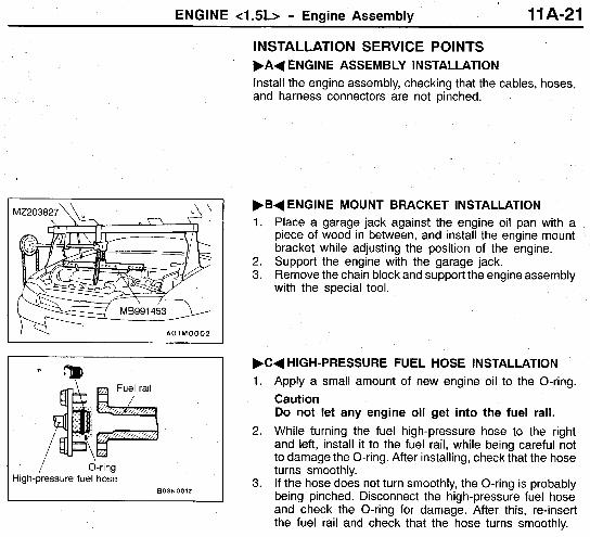
INSTALLATION SERVICE POINTS F A + ENGINE ASSEMBLY INSTALLATION Install the engine assembly, checking that the cables, hoses, and harness connectors are not pinched.
I\: A01M0002 I
Fuel rail + / O-ring
High-pressure fuel hose BOJN0012
FB+ ENGINE MOUNT BRACKET INSTALLATION 1. Place a garage jack against the engine oil pan with a
piece of wood in between, and install the engine mount bracket while adjusting the position of the engine.
2. Support the engine with the garage jack. 3. Remove the chain block and support the engine assembly
with the special tool.
F C + HIGH-PRESSURE FUEL HOSE INSTALLATION 1. Apply a small amount of new engine oil to the O-ring.
Caution Do not let any engine oil get into the fuel rail.
2. While turning the fuel high-pressure hose to the right and left, install it to the fuel rail, while being careful not to damage the O-ring. After installing, check that the hose turns smoothly.
3. If the hose does not turn smoothly, the O-ring is probably being pinched. Disconnect the high-pressure fuel hose and check the O-ring for damage. After this, re-insert the fuel rail and check that the hose turns smoothly.
11 A-22 ENGINE <1.5L> - Crankshaft Pulley
Pre-removal Operation 0 Under Cover Removal
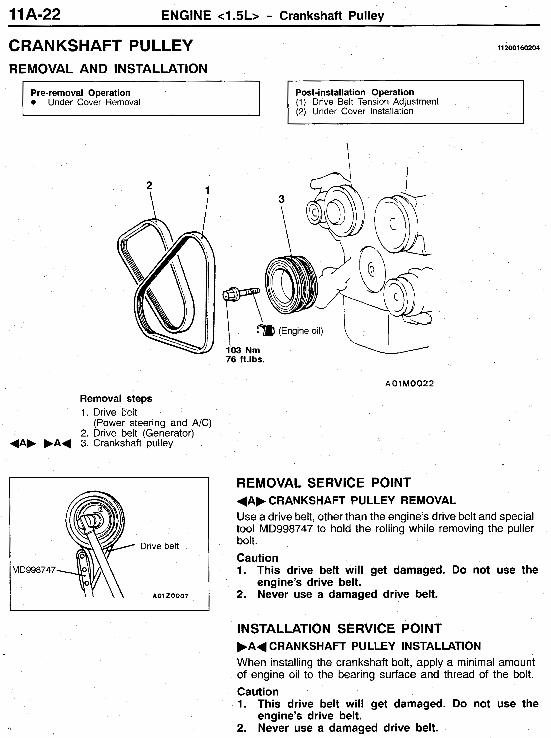
CRANKSHAFT PULLEY 112001 60204
Post-installation Operation (1) Drive Belt Tension Adjustment (2) Under Cover Installation
? 1 A I
I 103 Nrn 76 ft.lbs.
Removal steps 1. Drive belt
2. Drive belt (Generator) (Power steering and A/C)
4 A b ,A+ 3. Crankshaft pulley
REMOVAL SERVICE POINT
Drive belt
dD998747
A 0 1 20007
+AF CRANKSHAFT PULLEY REMOVAL Use a drive belt, other than the engine’s drive belt and special tool MD998747 to hold the rolling while removing the puller bolt.
Caution 1. This drive belt will get damaged. Do not use the
engine’s drive belt. 2. Never use a damaged drive belt.
IN STALLATION S E RVlC E POINT F A + CRANKSHAFT PULLEY INSTALLATION When installing the crankshaft bolt, apply a minimal amount of engine oil to the bearing surface and thread of the bolt. Caution 1. This drive belt will get damaged. Do not use the
engine’s drive belt. 2. Never use a damaged drive belt.
ENGINE <1.5L> - Camshaft and Camshaft Oil Seal 11 A-23
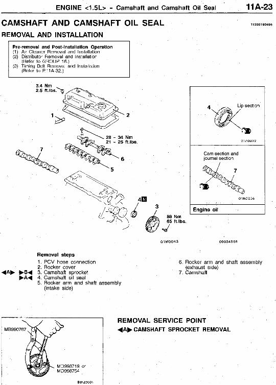
CAMSHAFT AND CAMSHAFT OIL SEAL 11 2001 90494
REMOVAL AND INSTALLATION
Pre-removal and Post-installation Operation (1) Air Cleaner Removal and Installation (2) Distributor Removal and Installation
(Refer to GROUP 16.) (3) Timing Belt Removal and Installation
(Refer to P. 11 A-32.)
3.4 Nm 2.5 ft.1bs.h
21 - 25 ft.lbS.
'/
3
01 MOO43
Removal steps
0120022
Cam section and journal section
01M0036
Engine oil
00004505
1. PCV hose connection 2. Rocker cover (exhaust side)
5. Rocker arm and shaft assembly
6. Rocker arm and shaft assembly
.B+ 3. Camshaft sprocket 7. Camshaft F A + 4. Camshaft oil seal
(intake side)
REMOVAL SERVICE POINT MB9907
MD998719 or
Bolzoool I
+ A F CAMSHAFT SPROCKET REMOVAL
11 A-24 ENGINE <1.5L> - Camshaft and Camshaft Oil Seal
I e
m /
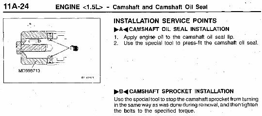
INSTALLATION SERVICE POINTS F A + CAMSHAFT OIL SEAL INSTALLATION 1. Apply engine oil to the camshaft oil seal lip. 2. Use the special tool to press-fit the camshaft oil seal. I
I MD998713
AOlXOOlS
FBd CAMSHAFT SPROCKET INSTALLATION Use the special tool to stop the camshaft sprocket from turning in the same way as was done during removal, and then tighten the bolts to the specified torque.
ENGINE <1.5L> - Oil Pan 11 A-25
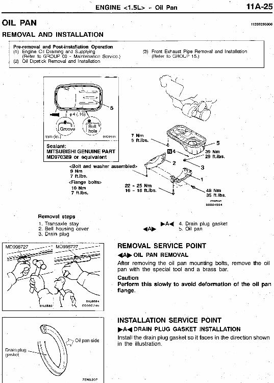
OIL PAN 11 200280306
REMOVAL AND INSTALLATION
Pre-removal and Post-installation Operation (1) Engine Oil Draining and Supplying (3) Front Exhaust Pipe Removal and Installation
(Refer to GROUP 00 - Maintenance Service.) (2) Oil Dipstick Removal and Installation
(Refer to GROUP 15.)
5
Sealant: MlTSUBlSHl GENUINE PART MD970389 or equivalent
9 Nm 7 ft.1b.s.
<Flange bolts> 10 Nrn 7 ft.lbs.
<Bolt and washer assemble
22 - 25 Nrn 16 - 18 ft.lbS.
Removal steps 1. Transaxle stay 2. Bell housing cover 3. Drain plug
7 EN 0 3 0 7
O*YOO24
00004504
.A( 4. Drain plug gasket (A. 5. Oil pan
REMOVAL SERVICE POINT +A,OIL PAN REMOVAL After removing the oil pan mounting bolts, remove the oil pan with the special tool and a brass bar. Caution Perform this slowly to avoid deformation of the oil pan flange.
INSTALLATION SERVICE POINT F A + DRAIN PLUG GASKET INSTALLATION Install the drain plug gasket so it faces in the direction shown in the illustration.
11 A-26 ENGINE c1.5L> - Crankshaft Oil Seal
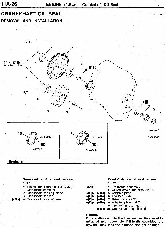
CRANKSHAFT OIL SEAL 11200310227
REMOVAL AND INSTALLATION
<M/T>
5 6
10 4
01z0021 01ZOC22
I Engine oil
Crankshaft front oil seal removal steps 0 Timing belt (Refer to P.11A-32.) 1. Crankshaft sprocket 2. Crankshaft sensing blade 3. Crankshaft spacer 4. Crankshaft front oil seal
Crankshaft rear oil seal removal steps 0 Transaxle assembly 0 Clutch cover and disc <M/T>
+BF .B+ 5. Adapter plate +BF .B+ 6. Flywheel <M/T> +B. .B+ 7. Drive plate <An> + B F .B+ 8. Adapter plate <M/T>
+A.
9. Crankshaft bushing .A+ 10. Crankshaft rear oil seal
Caution Do not disassemble the flywheel, as its runout is adjusted as an assembly. If it is disassembled, the flywheel may lose the balance and get damage.
ENGINE <1.5L> - Crankshaft Oil Seal 11 A-27
M/T
Flywheel
Bolt
A01M0154
Oil seal A7ENZ76 I
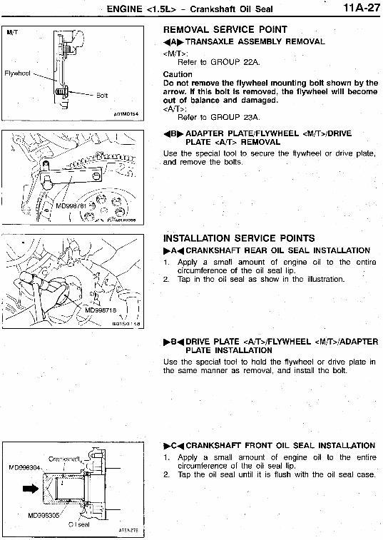
REMOVAL SERVICE POINT +AF TRANSAXLE ASSEMBLY REMOVAL <M/T>:
Caution Do not remove the flywheel mounting bolt shown by the arrow. If this bolt is removed, the flywheel will become out of balance and damaged. <An>:
Refer to GROUP 23A.
Refer to GROUP 22A.
.
+ B F ADAPTER PLATE/FLYWHEEL cM/T>/DRIVE
Use the special tool to secure the flywheel or drive plate, and remove the bolts.
PLATE <An> REMOVAL
INSTALLATION SERVICE POINTS F A + CRANKSHAFT REAR OIL SEAL INSTALLATION 1. Apply a small amount of engine oil to the entire
circumference of the oil seal lip. 2. Tap in the oil seal as show in the illustration.
F B + DRIVE PLATE cA/T>/FLYWHEEL cM/T>/ADAPTER
Use the special tool to hold the flywheel or drive plate in the same manner as removal, and install the bolt.
PLATE INSTALLATION
W C d CRANKSHAFT FRONT OIL SEAL INSTALLATION 1. Apply a small amount of engine oil to the entire
circumference of the oil seal lip. 2. Tap the oil seal until it is flush with the oil seal case.
11 A-28 ENGINE c1.5L> - Cylinder Head Gasket
CYLINDER HEAD GASKET REMOVAL AND INSTALLATION
11 200400771
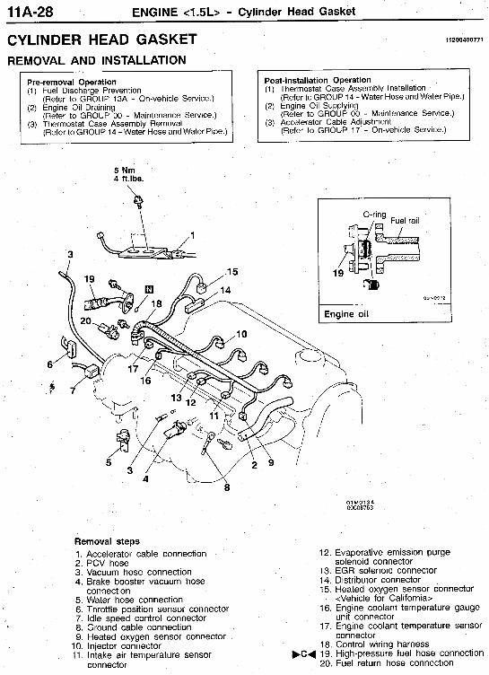
Pre-removal Operation (1) Fuel Discharge Prevention
(2) Engine Oil Draining
(3) Thermostat Case Assembly Removal
(Refer to GROUP 13A - On-vehicle Service.)
(Refer to GROUP 00 - Maintenance Service.)
(Refer to GROUP 14 - Water Hose and Water Pipe.)
Post-installation Operation (1) Thermostat Case Assembly Installation
(2) Engine Oil Supplying
(3) Accelerator Cable Adjustment
(Refer to GROUP 14 - Water Hose and Water Pipe.)
(Refer to GROUP 00 - Maintenance Service.)
(Refer to GROUP 17 - On-vehicle Service.)
5 Nm 4 ft.lbs.
01M0134 000087 6 3
Removal steps 1. Accelerator cable connection 2. PCV hose solenoid connector 3. Vacuum hose connection 4. Brake booster vacuum hose
5. Water hose connection 6. Throttle position sensor connector 7. Idle speed control connector 8. Ground cable connection 9. Heated oxygen sensor connector
12. Evaporative emission purge
13. EGR solenoid connector 14. Distributor connector 15. Heated oxygen sensor connector
16. Engine coolant temperature gauge
17. Engine coolant temperature sensor
18. Control wiring harness F C d 19. High-pressure fuel hose connection
20. Fuel return hose connection
connection <Vehicle for California>
unit connector
connector 10. Injector connector 11. Intake air temperature sensor
connector
ENGINE <1.5L> - Cylinder Head Gasket 11 A-29 \
.i
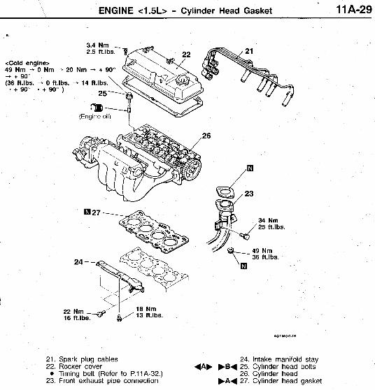
<Cold engine> 49 Nm - 0 Nm + 20 - + 90" (36 ft.lbS. - 0 ft.lbS. - --j + 90" - + 90" )
Nm - + 90"
(Engine oil) I
22 16
A O l M 0 0 3 8
21. Spark plug cables 24. Intake manifold stay 22. Rocker cover + A F F B I 25. Cylinder head bolts
23. Front exhaust pipe connection 0 Timing belt (Refer to P.11A-32.) 26. Cylinder head
F A + 27. Cylinder head gasket
11 A-30 '\ ENGINE <1.5L> - Cylinder Head Gasket
Intake side 0 Front of engine
01 Z 0005
00004766
Exhaust side
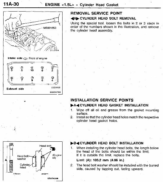
REMOVAL SERVICE POINT 4 A b CYLINDER HEAD BOLT REMOVAL Using the special tool, loosen the bolts in 2 or 3 steps in order of the numbers shown in the illustration, and remove the cylinder head assembly.
INSTALLATION SERVICE POINTS .A+ CYLINDER HEAD GASKET INSTALLATION 1. Wipe off all oil and grease from the gasket mounting
surface. 2. Install so that the cylinder head holes match the respective
cylinder head gasket holes.
01S0034 01CO~11
00004508 ~~
,B+ CYLINDER HEAD BOLT INSTALLATION 1. When installing the cylinder head bolts, the length below
the head of the bolts should be within the limit. If it is outside the limit, replace the bolts. Limit (A): 103.2 mm (4.06 in.)
2. The head bolt washer should be installed with the burred side, caused by tapping out, facing upward.
ENGINE <1.5L> - Cylinder Head Gasket 11 A-31
MB991653 ?i, ~ O l U O l L i 5
2 5 7 A
0120005
00004767
Exhaust side
0"
Painted mark Painted mark
01x0270
High-pressure fuel hose B03N0012
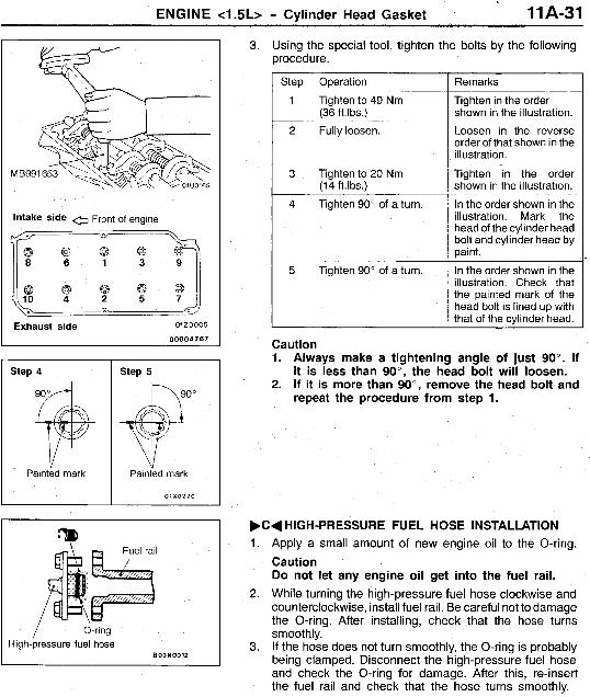
3. Using the special tool, tighten the bolts by the following procedure.
Step
1
2
3
4
5
Operation
Tighten to 49 Nm (36 ft.lbs.)
Fully loosen.
Tighten to 20 Nm (14 ft.lbs.)
Tighten 90" of a turn.
Tighten 90" of a turn,
Remarks
Tighten in the order shown in the illustration.
Loosen in the reverse order of that shown in the il I ustration.
Tighten in the order shown in the illustration.
In the order shown in the illustration. Mark the head of the cylinder head bolt and cylinder head by paint.
In the order shown in the illustration. Check that the painted mark of the head bolt is lined up with that of the cylinder head.
~- ~
Caution 1. Always make a tightening angle of just 90". If
it is less than 90°, the head bolt will loosen. 2. If it is more than go", remove the head bolt and
repeat the procedure from step 1.
F C d HIGH-PRESSURE FUEL HOSE INSTALLATION 1. Apply a small amount of new engine oil to the O-ring.
Caution Do not let any engine oil get into the fuel rail.
2. While turning the high-pressure fuel hose clockwise and counterclockwise, install fuel rail. Be careful not to damage the O-ring. After installing, check that the hose turns smoothly.
3. If the hose does not turn smoothly, the O-ring is probably being clamped. Disconnect the high-pressure fuel hose and check the O-ring for damage. After this, re-insert the fuel rail and check that the hose turns smoothly.
11 A-32 ENGINE <1.5L> - Timing Belt
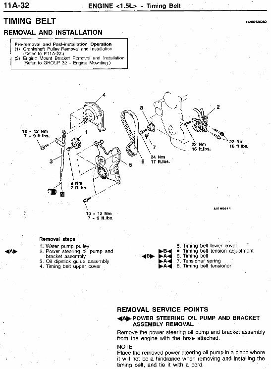
TIMING BELT REMOVAL AND INSTALLATION
(1) Crankshaft Pulley Removal and Installation (Refer to P.l l A-22.)
(2) Engine Mount Bracket Removal and Installation (Refer to GROUP 32 - Engine Mounting.)
11200430282
10 - 12 Nm
22 Nm 16 ft.lbs.
A01M0044
10 - 12 Nm 7 - 9 ft.lbS.
Removal steps 1. Water pump pulley 2. Power steering oil pump and
3. Oil dipstick guide assembly F A + 7. Tensioner spring 4. Timing belt upper cover F A + 8. Timing belt tensioner
5. Timing belt lower cover FB+ 0 Timing belt tension adjustment
bracket assembly +BF F A + 6. Timing belt + A F
REMOVAL SERVICE POINTS 4AFPOWER STEERING OIL PUMP AND BRACKET
ASSEMBLY REMOVAL Remove the power steering oil pump and bracket assembly from the engine with the hose attached. NOTE Place the removed power steering oil pump in a place where it will not be a hindrance when removing and installing the timinq belt, and tie it with a cord.
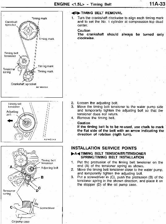
ENGINE <1.5L> - Timing Belt 11 A-33
Timing mark
iming mark
Timing mark
Timing mark
Crankshaft sprocket A O l M O O S O
‘Timing belt A\ ,/ tensioner
Timing mark Tensione spring Timing mark
Crankshaft sprocket A O l M O O S O
Timing belt tensioner , \\
A 0 1 M 0 0 4 9
spring \
Oil pump case
+Bb TIMING BELT REMOVAL Turn the crankshaft clockwise to align each timing mark and to set the No. 1 cylinder at compression top dead center. Caution The crankshaft should always be turned only clockwise.
Loosen the adjusting bolt. Move the timing belt tensioner to the water pump side and temporarily tighten the adjusting bolt so that the tensioner does not return. Remove the timing belt. Caution If the timing belt is to be re-used, use chalk to mark the flat side of the belt with an arrow indicating the direction of rotation (rigth turn).
INSTALLATION SERVICE POINTS .A+ TIMING BELT TENSIONERPENSIONER
SP R I N G/TI M IN G BELT IN STALLATION 1. Put the protrusion of the timing belt tensioner on the
end (A) of the tensioner spring as shown. 2. Move the timing belt tensioner close to the water pump,
and temporarily tighten the adjusting bolt. 3. Put a screwdriver in (C), push the protrusion (B) of the
tensioner spring in the shown direction, and place it on the stopper (D) of the oil pump case.
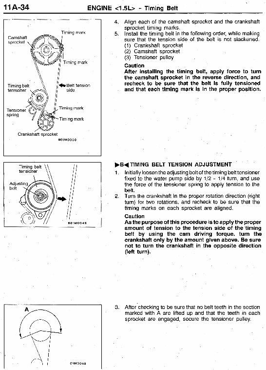
11 A-34 ENGINE <1.5L> - Timing Belt
1
Crankshaft sprocket 801M0050
4.
5.
Align each of the camshaft sprocket and the crankshaft sprocket timing marks. Install the timing belt in the following order, while making sure that the tension side of the belt is not slackened. (1) Crankshaft sprocket (2) Camshaft sprocket (3) Tensioner pulley Caution After installing the timing belt, apply force to turn the camshaft sprocket in the reverse direction, and recheck to be sure that the belt is fully tensioned and that each timing mark is in the proper position.
I FBdTlMlNG BELT TENSION ADJUSTMENT 1. Initially loosen the adjusting bolt of the timing belt tensioner
fixed to the water pump side by 1/2 - 1/4 turn, and use the force of the tensioner spring to apply tension to the belt.
2. Turn the crankshaft in the proper rotation direction (right turn) for two rotations, and recheck to be sure that the timing marks on each sprocket are aligned. Caution As the purpose of this procedure is to apply the proper amount of tension to the tension side of the timing belt by using the cam driving torque, turn the crankshaft only by the amount given above. Be sure not to turn the crankshaft in the opposite direction (left turn).
3. After-checking to be sure that no belt teeth in the section marked with A are lifted up and that the teeth in each sprocket are engaged, secure the tensioner pulley.