Embed Size (px)
Citation preview
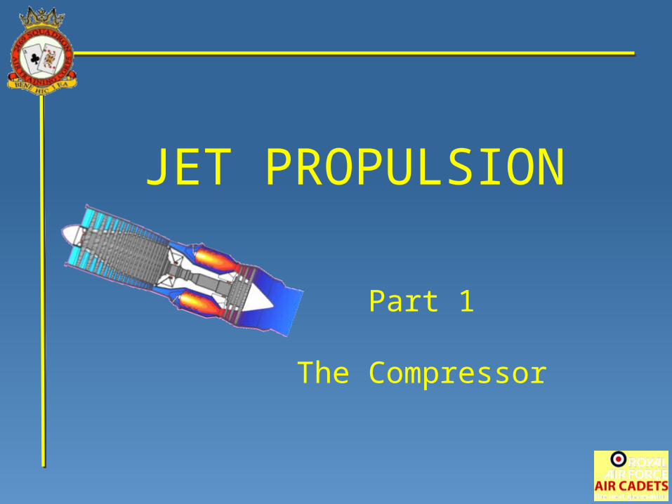
JET PROPULSION
Part 1
The Compressor
The principle of jet propulsion
was demonstrated by Hero of Alexandria
as long ago as the first century AD.
However, the jet engine, as we know it,
did not become a practical possibility
until 1930 when Sir Frank Whittle patented
the design of his first reaction motor
suitable for aircraft propulsion.
Introduction
The gas turbine engine,
commonly referred to as the ‘jet’ engine,
is an internal combustion engine which
produces power by the controlled burning of fuel.
In both the gas turbine and the motor car engine
air is compressed,
fuel is mixed with it, and the mixture is burnt.
The heat which results produces
a rapid expansion of the gas
and this is used to do work.
Introduction
COMPRESSOR TURBINE
COMBUSTION
CHAMBER
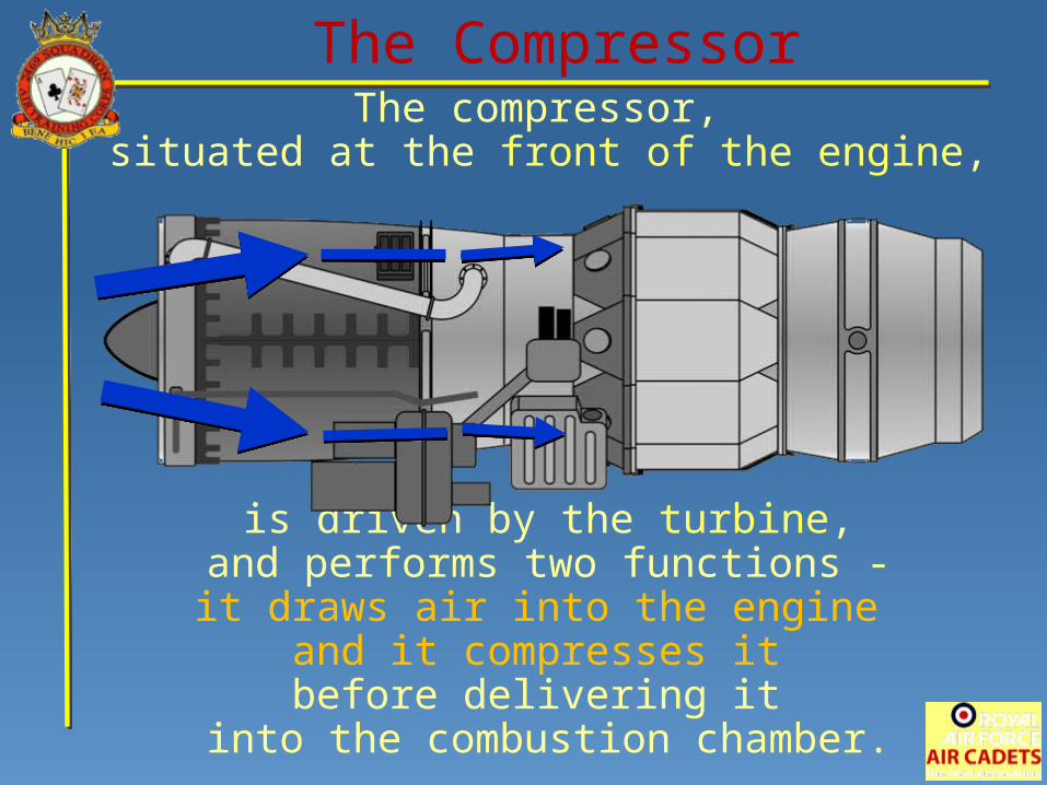
The compressor, situated at the front of the engine,
is driven by the turbine,and performs two functions -it draws air into the engine
and it compresses it before delivering it
into the combustion chamber.
The Compressor
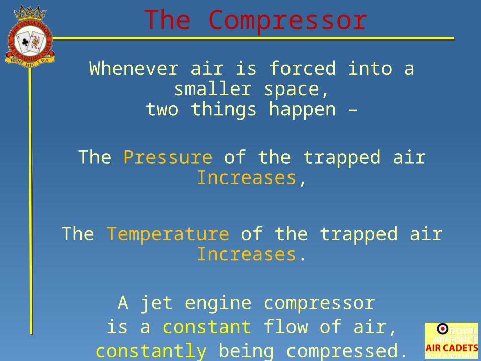
Whenever air is forced into a smaller space,two things happen –
The Pressure of the trapped air Increases,
The Temperature of the trapped air Increases.
A jet engine compressor is a constant flow of air,
constantly being compressed.
The Compressor
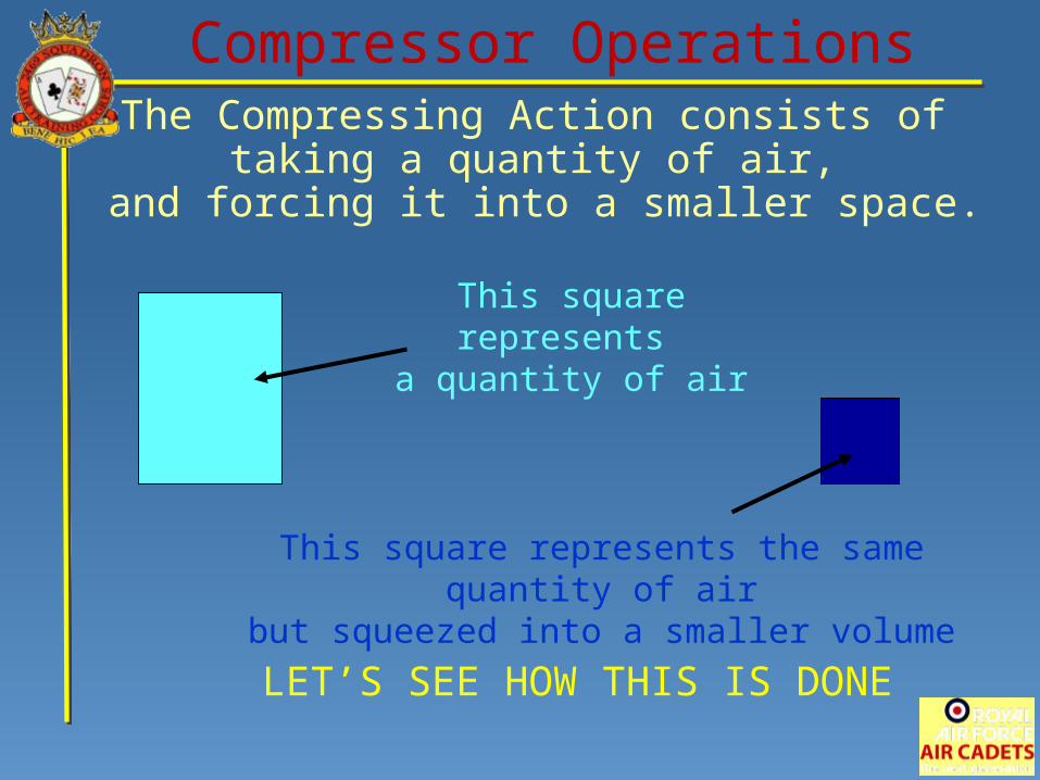
The Compressing Action consists of taking a quantity of air,
and forcing it into a smaller space.
This square represents a quantity of air
This square represents the same quantity of airbut squeezed into a smaller volume
LET’S SEE HOW THIS IS DONE
Compressor Operations
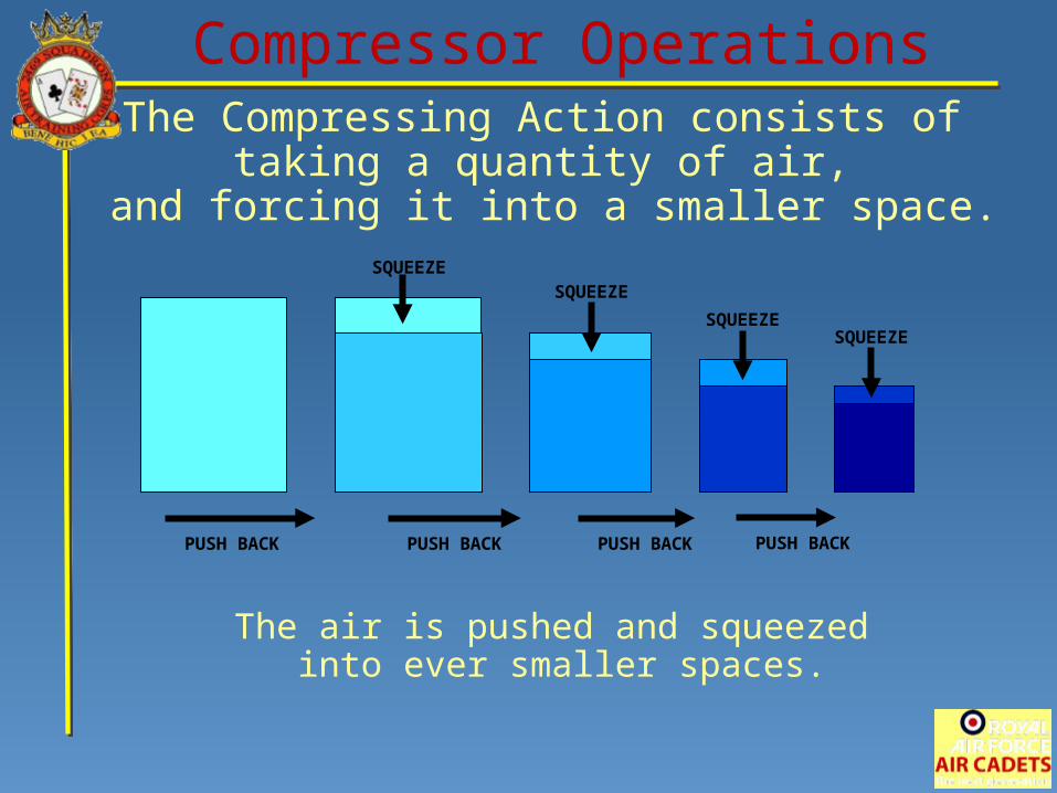
The Compressing Action consists of taking a quantity of air,
and forcing it into a smaller space.
Compressor Operations
PUSH BACK
SQUEEZE
PUSH BACK PUSH BACK PUSH BACK
SQUEEZE
SQUEEZESQUEEZE
The air is pushed and squeezed into ever smaller spaces.
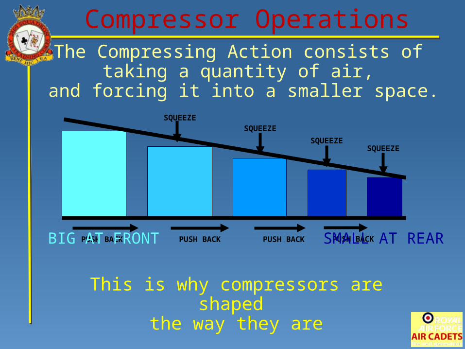
The Compressing Action consists of taking a quantity of air,
and forcing it into a smaller space.
This is why compressors are shaped the way they are
Compressor Operations
PUSH BACK PUSH BACK PUSH BACK PUSH BACKBIG AT FRONT SMALL AT REAR
SQUEEZESQUEEZE
SQUEEZESQUEEZE
BIG AT FRONT SMALL AT REAR
Compressor Operations
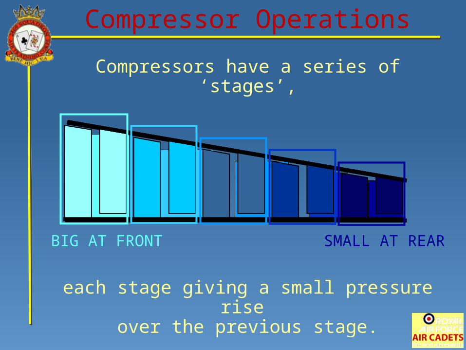
Compressors have a series of ‘stages’,
each stage giving a small pressure rise over the previous stage.
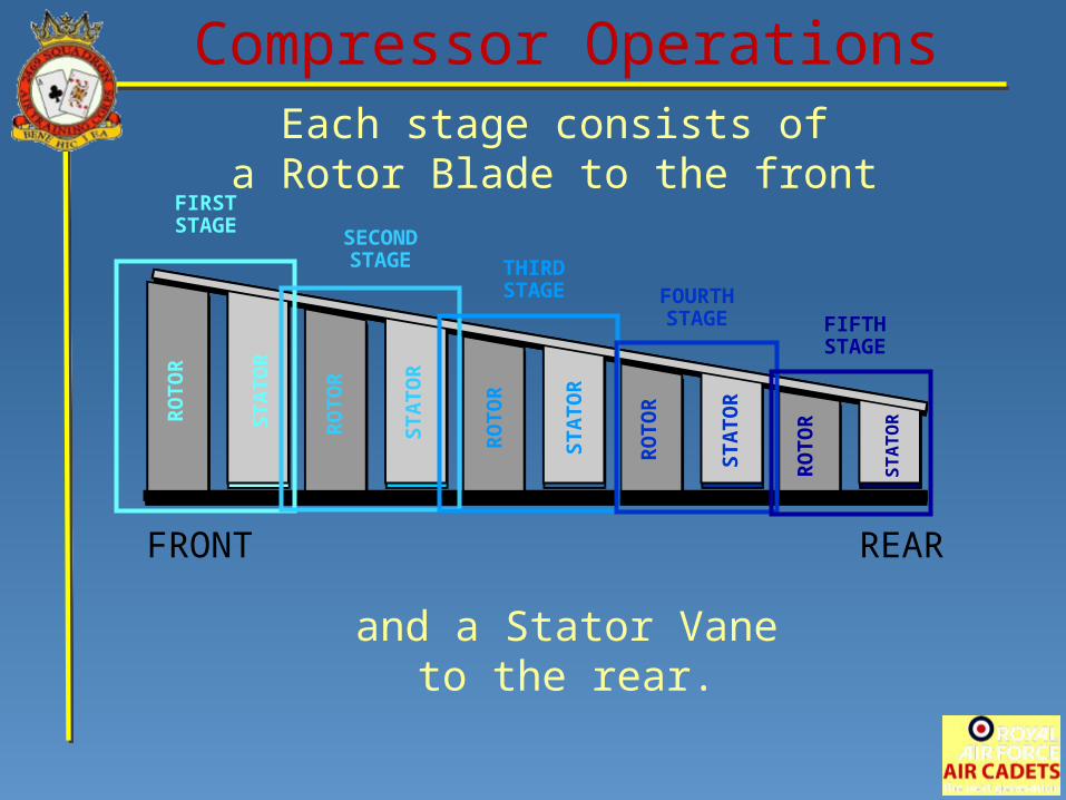
Compressor OperationsEach stage consists of
a Rotor Blade to the front
and a Stator Vaneto the rear.
FRONT REAR
FIRSTSTAGE
SECONDSTAGE THIRD
STAGE FOURTHSTAGE FIFTH
STAGE
RO
TO
R
STA
TO
R
RO
TO
R
STA
TO
R
RO
TO
R
STA
TO
R
RO
TO
R
STA
TO
R
RO
TO
R
STA
TO
R
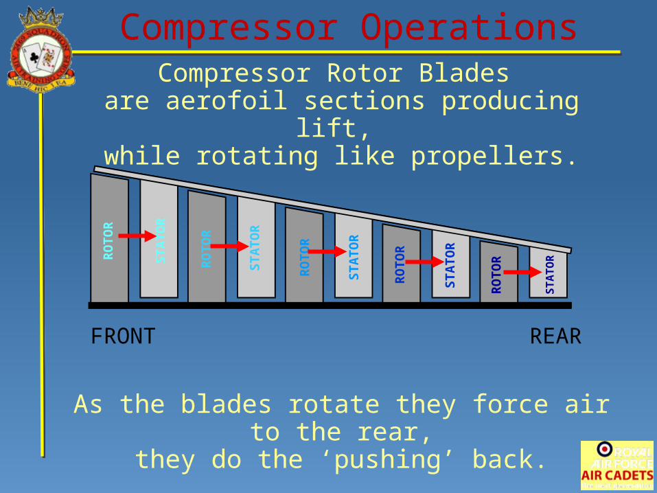
Compressor Rotor Blades are aerofoil sections producing lift,
while rotating like propellers.
As the blades rotate they force air to the rear,they do the ‘pushing’ back.
Compressor Operations
FRONT REAR
RO
TO
R
STA
TO
R
RO
TO
R
STA
TO
R
RO
TO
R
STA
TO
R
RO
TO
R
STA
TO
R
RO
TO
R
STA
TO
R
Compressor Operations
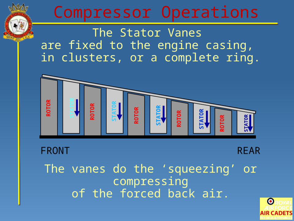
FRONT REAR
The Stator Vanes are fixed to the engine casing, in clusters, or a complete ring.
The vanes do the ‘squeezing’ or compressing
of the forced back air.
RO
TO
R
STA
TO
R
RO
TO
R
STA
TO
R
RO
TO
R
STA
TO
R
RO
TO
R
STA
TO
R
RO
TO
R
STA
TO
R
Compressor Operations
FRONT REAR
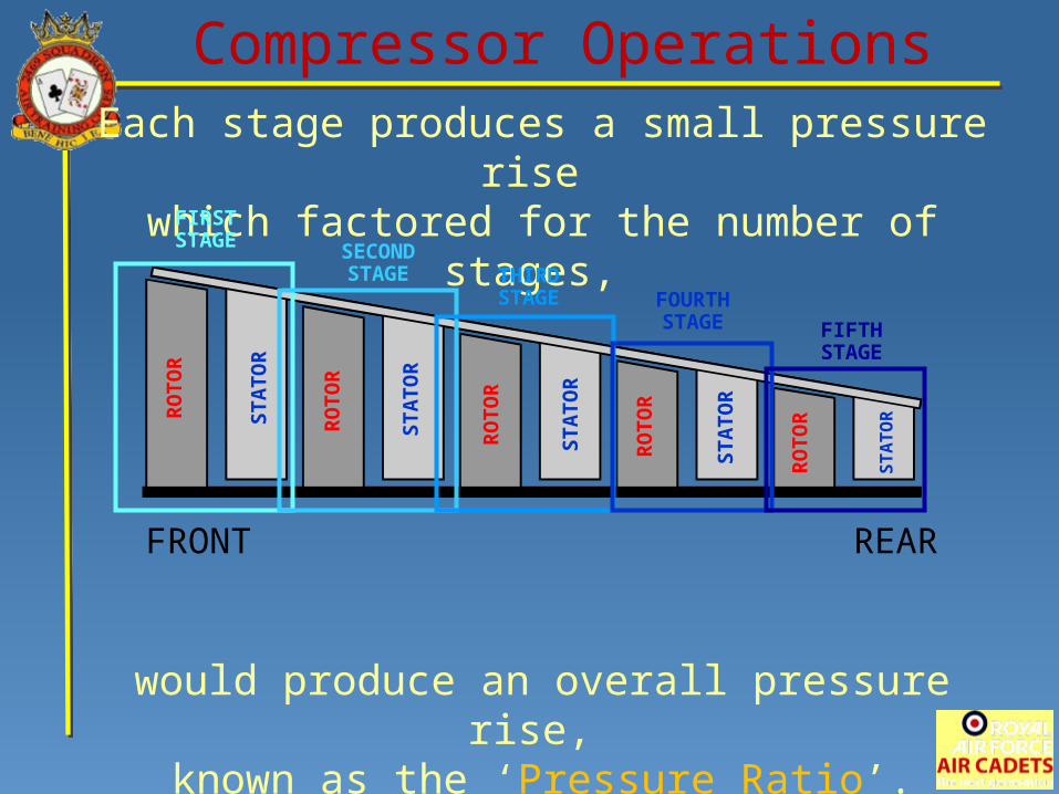
Each stage produces a small pressure rise which factored for the number of stages,
would produce an overall pressure rise, known as the ‘Pressure Ratio’.
Pressure ratios around 26:1 are common.(meaning pressure is 26 times ambient)
RO
TO
R
STA
TO
R
RO
TO
R
STA
TO
R
RO
TO
R
STA
TO
R
RO
TO
R
STA
TO
R
RO
TO
R
STA
TO
R
FIRSTSTAGE SECOND
STAGE THIRDSTAGE FOURTH
STAGE FIFTHSTAGE
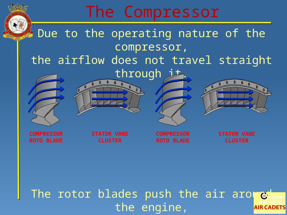
Due to the operating nature of the compressor,the airflow does not travel straight through it.
The rotor blades push the air around the engine,whereas the stator vanes straighten it out.
COMPRESSORROTO BLADE
COMPRESSORROTO BLADE
STATOR VANECLUSTER
STATOR VANECLUSTER
The Compressor
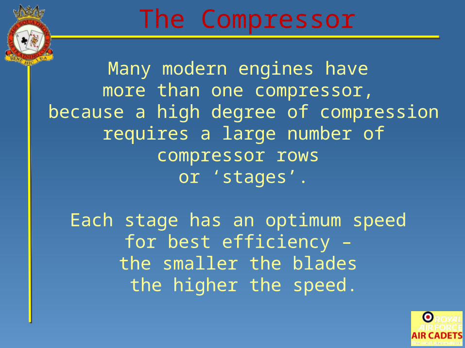
Many modern engines have more than one compressor,
because a high degree of compression requires a large number of compressor rows
or ‘stages’.
Each stage has an optimum speed for best efficiency –
the smaller the blades the higher the speed.
The Compressor
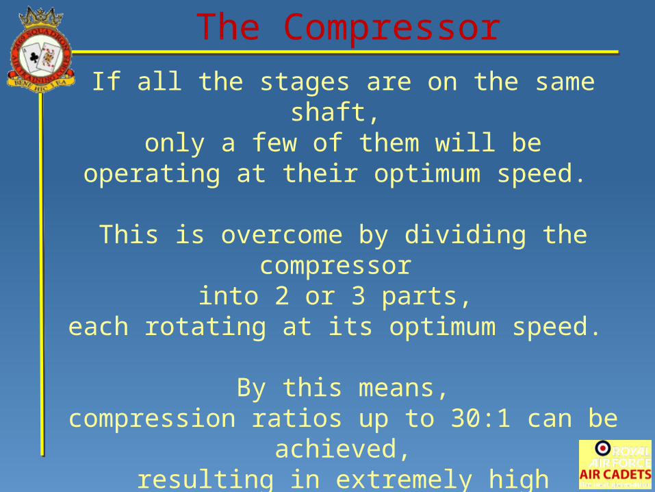
If all the stages are on the same shaft, only a few of them will be
operating at their optimum speed.
This is overcome by dividing the compressor into 2 or 3 parts,
each rotating at its optimum speed.
By this means,compression ratios up to 30:1 can be achieved,
resulting in extremely high efficiencyand very low specific fuel consumption.
The Compressor
Check of Understanding
When air is forced into a smaller space,what two things happen?
Pressure DecreasesTemperature Increases
Pressure IncreasesTemperature Decreases
Pressure DecreasesTemperature Decreases
Pressure IncreasesTemperature Increases
What does each stage of a compressorconsist of?
Rotor vanes and Stator blades
Rotor vanes and Compressor blades
Rotor blades and Compressor vanes
Rotor blades and Stator vanes
Check of Understanding
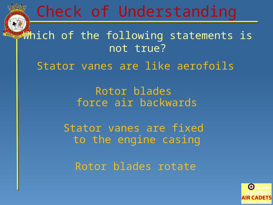
Which of the following statements is not true?
Rotor blades rotate
Stator vanes are like aerofoils
Stator vanes are fixed to the engine casing
Rotor blades force air backwards
Check of Understanding
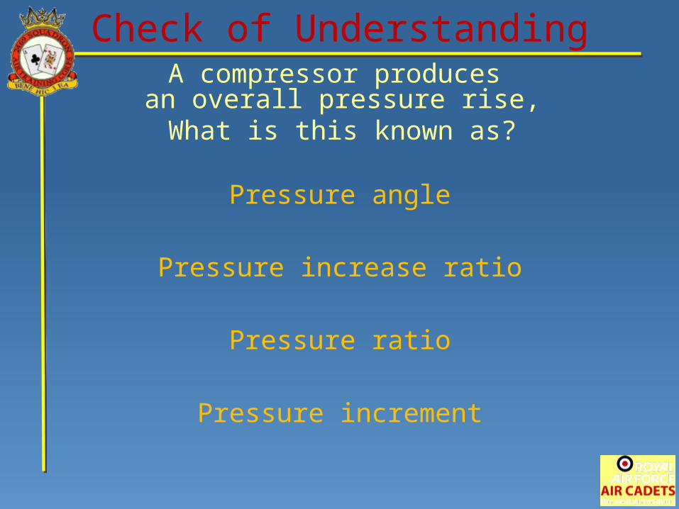
A compressor produces an overall pressure rise,What is this known as?
Pressure increment
Pressure angle
Pressure ratio
Pressure increase ratio
Check of Understanding
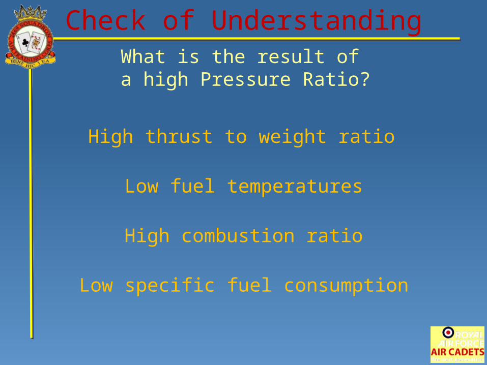
What is the result of a high Pressure Ratio?
Low specific fuel consumption
High thrust to weight ratio
High combustion ratio
Low fuel temperatures
Check of Understanding
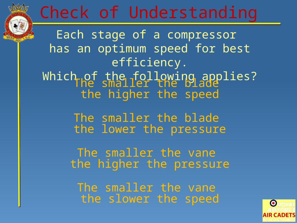
Each stage of a compressor has an optimum speed for best efficiency.
Which of the following applies?
The smaller the vane the slower the speed
The smaller the blade the higher the speed
The smaller the vane the higher the pressure
The smaller the blade the lower the pressure
Check of Understanding

JET PROPULSION
End of Presentation