Embed Size (px)
Citation preview

403235_RLF_Rev1.1_080714
Jet Propulsion System
Jet Propulsion System
• 403233_JetPropulsionSystem104V320073.1• 403234_JetPropulsionSystem104V420073.1• 103820_JetPropulsionSystem143V120073.1• 403235_JetPropulsionSystem143V220073.1• 403134_JetPropulsionSystem66V120082.1• 403238_JetPropulsionSystem66V220082.1
Repair Manual
Thisrepairmanualisvalidforthefollowingjetpumpvariants:
403235_RLF_Rev1.1_080714
Jet Propulsion SystemRepair Manual
Table of Contents
1 Beforeyoubeginworking 1
2 EquipmentandSpecialTools 1
3 Removingthejetpumpfromthevehicle 2
3.1 RemovingHousing 33.2 RemovingRideplate,GrateundInletScoop 43.3 RemovingDriveshaft 53.4 RemovingDriveCoupler 7
4 Disassemblingthejetpump 8
4.1 RemovingReverseGateandSteeringNozzle 84.2 RemovingWaterTubeandPumpWedge 104.3 RemovingStator 11
5 Aligningtheenginewithinthevehicle 14
Terminology 19

403235_RLF_Rev1.1_080714
Jet Propulsion System
Page 1
Repair Manual
1 Before you begin working
2 Equipment and Special Tools
- MountingTool Impeller.Seesparepartscatalogue.Chapter:Disassembling the jetpump,Stator.
- AlignmentLaserToolCase.Seesparepartscatalogue.OnlyinconjunctionwithanWeberAutomotiveGmbHengine.Chapter:Aligningtheenginewithinthevehicle.
- Marinegrease.LubricatinggreaseappropriateforMarineuse. The Weber Automotive GmbH recommends a premium multipurpose lubricating grease.
Resistant to freshwaterandsaltwater.Sustainedoperating temperature: -60°C[-80°F] to+200°C[+400°F].Droppingpoint>250°C[500°F].
- SealingagentappropriateforMarineuse TheWeberAutomotiveGmbHrecommendsaone-componentpolyurethanesealantsuitable
forproducingelasticandvibration-proofsealedjoints.Resistanttofreshwaterandsaltwater.Temporarilyresistanttofuelandpetroleum.Sustainedoperatingtemperature:-40°C[-40°F]to+90°C[+195°F]
- Loctite272forsecuringandsealingthescrewcoupling.Chapter:Reversegateandsteeringnozzle.
- Loctite243forsecuringandsealingthescrewcoupling.
Rotatingpartsonthedriveshaftandtheimpellercancauseseriouslacerations.
Beforebeginningworkofanykindonthejetpump,removeignitionkeyandlanyardanddetachcableonbatteryfromnegativeterminal.
WARNING
Disassemblyisdescribedintherepairmanual.Assemblyiscarriedoutinreverseorder.PleaseobservenotesfollowingthisSymbol.
Thevehiclemanufacturer’sservicemanualmaybeneededasasupplementtothisrepairmanual.

403235_RLF_Rev1.1_080714
Jet Propulsion System
1
2
3
Page 2
Repair Manual
3 Removing the jet pump from the vehicle
Tighteningtorque:
20Nm±10%[14ft.lb.]
UsethreadlockLoctite243.
1) Remove cable for the steeringnozzle (1) and the reverse gate(2).
See the vehicle manufacturer‘sservicemanual.
2) Remove5/16-18UNC-2Bbolts(3).
Rotatingpartsonthedriveshaftandtheimpellercancauseseriouslacerations.
Beforebeginningworkofanykindonthejetpump,removeignitionkeyandlanyardanddetachcableonbatteryfromnegativeterminal.
WARNING
403235_RLF_Rev1.1_080714
Jet Propulsion System
2
1011
5
4
Page 3
Repair Manual
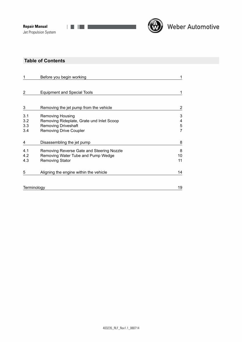
1) Loosen the nuts (1) inside thevehicle and remove the housing.Remove ride plate beforehand ifnecessary.
3.1 Removing Housing
Replacenuts.
Applysealingagent(2)asshownandattachhousing.
See vehicle manufacturer’sservice manual for additionalinformation.
Removingthejetpumpfromthevehicle(continuation)
3) Remove seawater cooling tube.Remove jet pump (4) fromhousing.
Lubricatesurface(5)withmarinegrease.
The freely rotating impeller can jam or severfingers.
Neverholdthejetpumpontheimpellerorreachin.
WARNING
Whenapplyingsealingagent,ensurethatitstaysawayfromscrewthreads,water connections, or water hoses. Sealing agent residue can lead toblockagesinthewatersystem.

403235_RLF_Rev1.1_080714
Jet Propulsion System
1
2
3
4
4
4
4
4
Page 4
Repair Manual
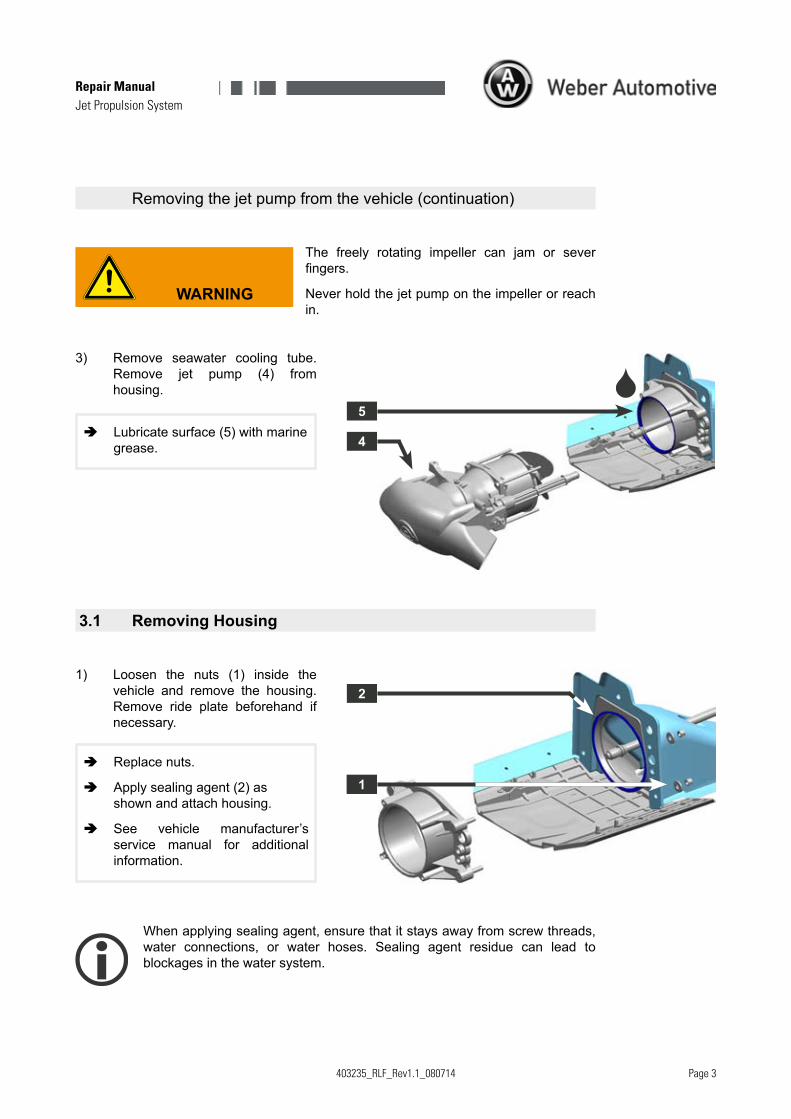
3.2 Removing Rideplate, Grate und Inlet Scoop
1) Removerideplate(1).
2) Removegrate(2).
3) Removeinletscoop(3).
Applysealingagent(4)asshownandattach rideplate,grate,andinletscoop.
See also vehicle manufacturer’sservicemanual.
Applysealingagentcarefullytopreventanairgap.Thejetpumpcouldtakeinsupplementaryair,whichwouldleadtopowerlosses.

403235_RLF_Rev1.1_080714
Jet Propulsion System
1
2
3
4
8
7
6
6
5
optional
Page 5
Repair Manual
3.3 Removing Driveshaft
1) Remove driveshaft (1) from drivecoupling(2).Carefullydisassembleseal (3) to avoid damaging theseal.
Mountseal(3)anddampingbearing(4)withmarinegrease.
Fill seal with marine grease viathe lubricatingnipple (5)withangreasegun.
Assemble the damping bearing(4).See thevehiclemanufactur-er’sservicemanual.
ReplaceO-ring(7).
MountO-ringandbothbuffers(8)withmarinegrease.
Before installing driveshaft, always check to make sure both bumpers areinstalled.Missingbumpersleadtoanunacceptablylargeaxialclearanceandcancausedamage,forexample,tothedriveshaftorthedrivecoupler.
2) Ifthesealsofthesealrings(6)weredamaged when disassemblingthe seal, the seal rings must bereplaced.
Mountsealringsandsleevewithmarinegrease.
Observe the orientation of thesealrings.

403235_RLF_Rev1.1_080714
Jet Propulsion System
1
1
2
Page �
Repair Manual
Checking Driveshaft
Rotation:
1) LaythecleaneddriveshaftontwoV-blocks(1).Rotatethedriveshaftandmeasureatpoint(2)withadialgauge.
Maximum acceptable deviation:
0,13 mm [0.005 in.]
2) The driveshaft must be replacedif thedeviationisgreaterthanthemaximumacceptabledeviation.
Axialclearance:
1) Check the axial clearance in thevehicle with mounted engine, jetpump,sealanddampingbearing.
Move thedriveshaft in the indica-teddirectionbackandforth.
Required axial clearance:
Minimum 4 mm [0.16 in.]
Maximum 7 mm [0.28 in.]
2) Iftheaxialclearanceisoutsidetherequiredaxialclearancetheenginemustbeaccordinglyaligned.
See chapter aligning the enginewithinthevehicle.
Toolittleaxialclearancecausesseveredamagetoengineand/orjetpump.

403235_RLF_Rev1.1_080714
Jet Propulsion System
2
1
3
Page 7
Repair Manual
3.4 Removing Drive Coupler
1) Secure the flywheel (1) on the marked points and unscrew thedrivecoupler(2).
Hand-screw the drive couplersturdilyontothestubshaft(3).
Right-handthread.
Whenmounting,thedrivecouplingisscrewedontothecouplingelementonlyhand-tight.Whendriving,thedrivecouplingwilltightenitself.

403235_RLF_Rev1.1_080714
Jet Propulsion System
5
3
2
4
1
1
2
3
Page 8
Repair Manual
After removal from the vehicle, thejet pump separates into the followingcomponents:
(1)Reversegateandsteeringnozzle
(2)Pumpwedge
(3)Stator
(4)Watertube
(5)Housing
4 Disassembling the jet pump
Tighteningtorque:
20Nm±10%[14ft.lb.]
UsethreadlockLoctite272
Tighteningtorque:
20Nm±10%[14ft.lb.]
UsethreadlockLoctite243.
4.1 Removing Reverse Gate and Steering Nozzle
The freely rotating impeller can jam or severfingers.
Neverholdthejetpumpontheimpellerorreachin.
WARNING
1) Remove M8 bolts (1) on bothsides.
2) Remove(2)reversegate.
3) RemoveM8bolts(3)forstopper.

403235_RLF_Rev1.1_080714
Jet Propulsion System
4
5
7
6
8
Page �
Repair Manual
Tighteningtorque:
20Nm±10%[14ft.lb.]
UsethreadlockLoctite243.
Applysealingagent(8)asshownand attach screen. Observe ori-entation.
Theopeningsinthescreenmustbefreeandclean.
RemovingReverseGateandSteeringNozzle(continuation)
4) RemoveM8bolts(4).
5) Removesteeringnozzle(5).
6) When removing the screen, thescreen receiver in the jet nozzlemustnotbedamaged.

403235_RLF_Rev1.1_080714
Jet Propulsion System
1
1
2
Page 10
Repair Manual
4.2 Removing Water Tube and Pump Wedge
Replace seals (1) on waterpipe and lubricate with marinegrease.
Observeorientationonpumpwedge(2).
Thenarrowsidewiththemarkingnosemustfaceupwards.

403235_RLF_Rev1.1_080714
Jet Propulsion System
1
2
3
4
Page 11
Repair Manual
4.3 Removing Stator
Tighteningtorque:
4.5Nm±10%[3.3ft.lb.]
UsethreadlockLoctite243.
Replaceseal.
Tighteningtorque:
138Nm±10%[101ft.lb.]
Usenogreaseorliquidthreadlocktomounttheimpeller.
Right-handthread.
Afterassembly,checkmovementofimpeller.
The freely rotating impeller can jam or severfingers.
Neverholdthejetpumpontheimpellerorreachin.
WARNING
1) RemoveM5bolts(1).
2) Remove pump cone (2) and seal(3).
3) Removeimpeller(4)withmountingtoolimpeller.
403235_RLF_Rev1.1_080714
Jet Propulsion System
9
8
7
6
5
Page 12
Repair Manual
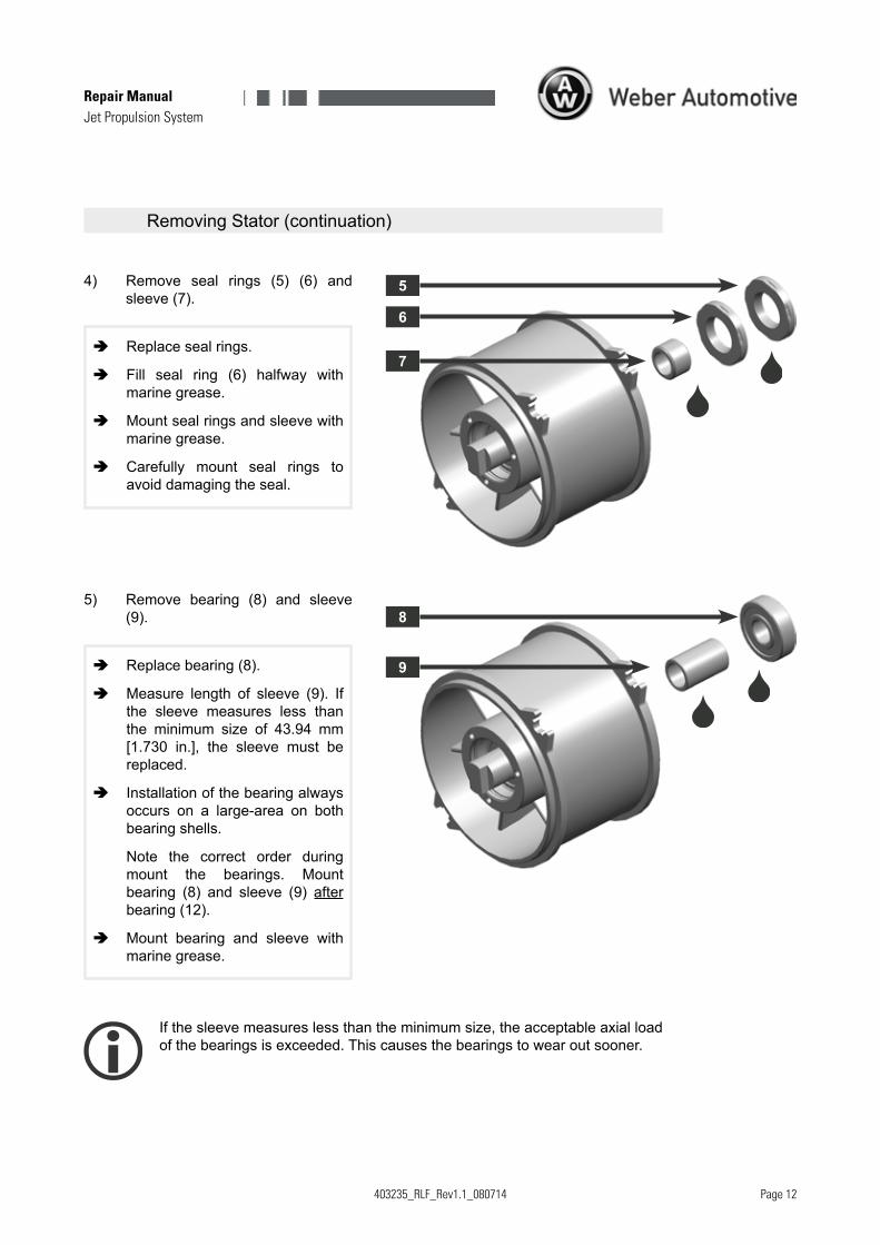
Replacebearing(8).
Measure length of sleeve (9). Ifthe sleeve measures less thanthe minimum size of 43.94 mm[1.730 in.], the sleeve must bereplaced.
Installationofthebearingalwaysoccurs on a large-area on bothbearingshells.
Note the correct order duringmount the bearings. Mountbearing (8) and sleeve (9) afterbearing(12).
Mount bearing and sleeve withmarinegrease.
Replacesealrings.
Fill seal ring (6) halfway withmarinegrease.
Mountsealringsandsleevewithmarinegrease.
Carefully mount seal rings toavoiddamagingtheseal.
RemovingStator(continuation)
5) Remove bearing (8) and sleeve(9).
Ifthesleevemeasureslessthantheminimumsize,theacceptableaxialloadofthebearingsisexceeded.Thiscausesthebearingstowearoutsooner.
4) Remove seal rings (5) (6) andsleeve(7).
403235_RLF_Rev1.1_080714
Jet Propulsion System
10
11
12
Page 13
Repair Manual
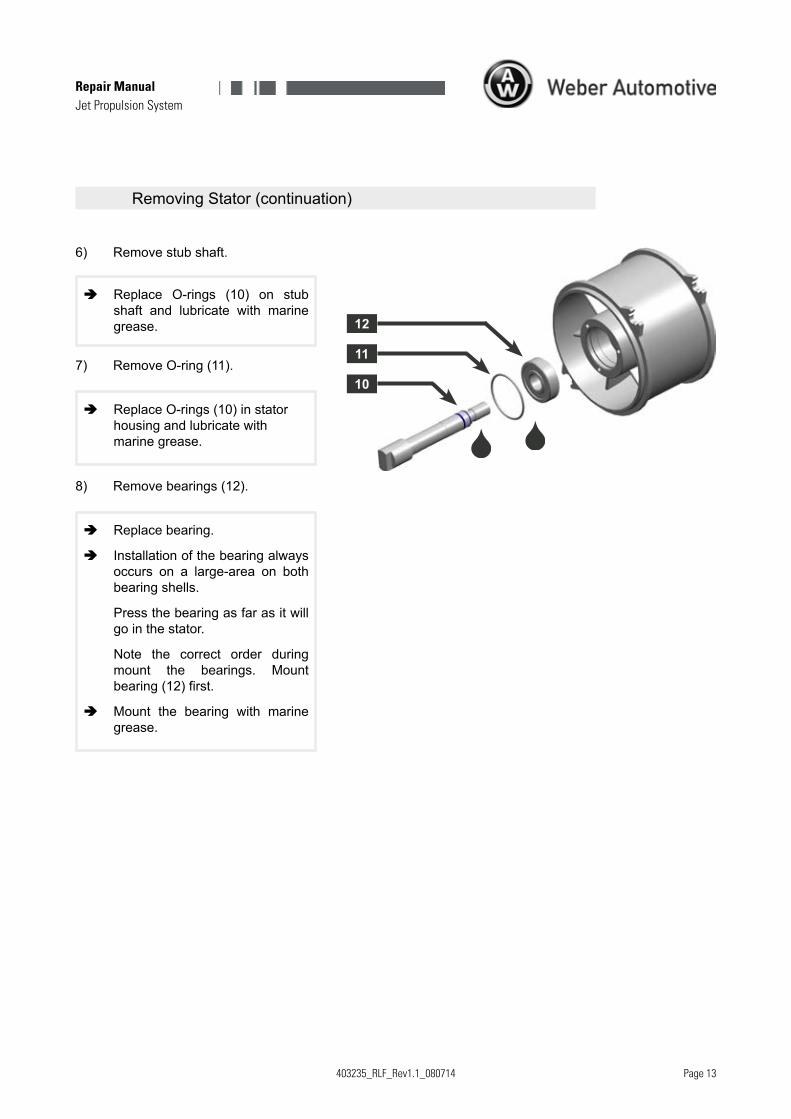
Replace O-rings (10) on stubshaft and lubricate with marinegrease.
Replacebearing.
Installationofthebearingalwaysoccurs on a large-area on bothbearingshells.
Pressthebearingasfarasitwillgointhestator.
Note the correct order duringmount the bearings. Mountbearing(12)first.
Mount the bearing with marinegrease.
ReplaceO-rings(10)instatorhousingandlubricatewithmarinegrease.
RemovingStator(continuation)
6) Removestubshaft.
8) Removebearings(12).
7) RemoveO-ring(11).

403235_RLF_Rev1.1_080714
Jet Propulsion System
1
2
3
Page 14
Repair Manual
Rotatingpartsonthedriveshaftandtheimpellercancauseseriouslacerations.
Beforebeginningworkofanykindonthejetpump,removeignitionkeyandlanyardanddetachcableonbatteryfromnegativeterminal.
WARNING
5 Aligning the engine within the vehicle
Theenginemustbealignedwithinthevehicle,if...
... theenginewasremoved.
... theenginemountswereremovedorreplaced.
ThischapterisonlyvalidinconjunctionwithaWeberAutomotiveGmbHen-gine.
- AlignmentLaserToolCase
1) Removejetpump(1)anddriveshaftwithseal(2)andifexistant,damp-ingbearingfromthevehicle.
Seechapterremovingthejetpumpfrom the vehicle and removingdriveshaft.
2) Removedrivecoupler(3).
Seechapterremovingdrivecoup-ler.

403235_RLF_Rev1.1_080714
Jet Propulsion System
6
5
4
Page 15
Repair Manual
Aligning the engine within the vehicle (continuation)
WARNING
The alignment laser (4) is in accordancewith class 2 international standards. The ma-ximum value of average radiant power is1mW.Thevisiblecolourisred.
Thelaserbeamofthealignmentlasercancauseeyedamage.
- Donotlookintothelaserbeam(5).
- Neverdirectthelaserbeamatotherpeople.
- Thealignmentlaserhasnoon/offswitch.Ifthepowersupply isconnected, thealignment la-serisinoperation.Donotconnectthepowersupply(6)untilallpreparatonhasbeendone.
- If signs of damage are shown discontinueuse.
- Donotremovethewarninglabelsfromtheali-gnmentlaser.
403235_RLF_Rev1.1_080714
Jet Propulsion System
9
7
4
8
11
10
3 V
Page 1�
Repair Manual
Aligning the engine within the vehicle (continuation)
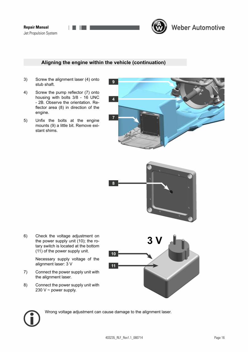
3) Screwthealignmentlaser(4)ontostubshaft.
4) Screw the pump reflector (7) onto housing with bolts 3/8 - 16 UNC-2B.Observetheorientation.Re-flector area (8) in direction of the engine.
5) Unfix the bolts at the engine mounts(9)alittlebit.Removeexi-stantshims.
6) Check the voltage adjustment onthepowersupplyunit(10);thero-taryswitchislocatedatthebottom(11)ofthepowersupplyunit.
Necessary supply voltage of thealignmentlaser:3V
7) Connectthepowersupplyunitwiththealignmentlaser.
8) Connectthepowersupplyunitwith230V~powersupply.
Wrongvoltageadjustmentcancausedamagetothealignmentlaser.
403235_RLF_Rev1.1_080714
Jet Propulsion System
13
12
14
16
15
Page 17
Repair Manual
Aligning the engine within the vehicle (continuation)
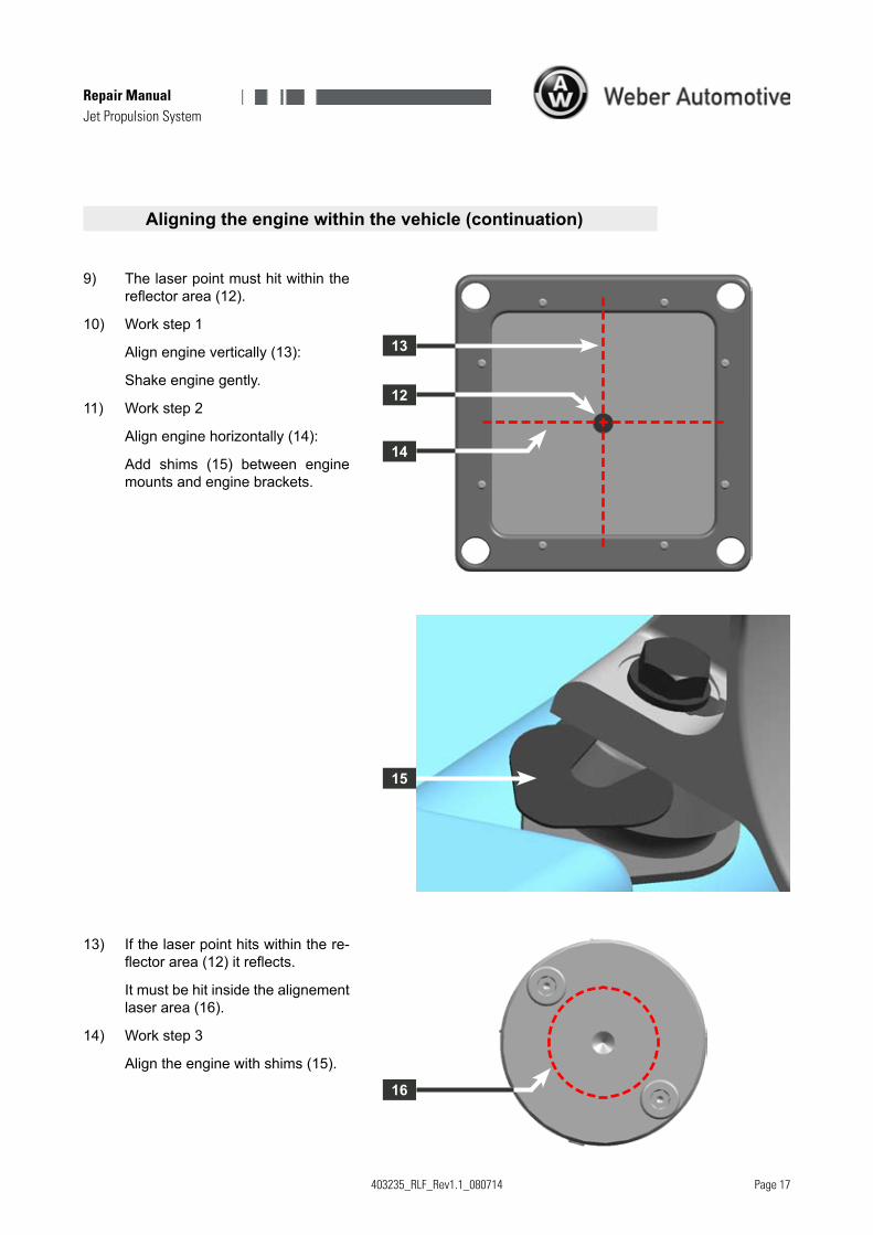
9) Thelaserpointmusthitwithinthereflector area (12).
10) Workstep1
Alignenginevertically(13):
Shakeenginegently.
11) Workstep2
Alignenginehorizontally(14):
Add shims (15) between enginemountsandenginebrackets.
13) Ifthelaserpointhitswithinthere-flector area (12) it reflects.
Itmustbehitinsidethealignementlaserarea(16).
14) Workstep3
Aligntheenginewithshims(15).
403235_RLF_Rev1.1_080714
Jet Propulsion System
Page 18
Repair Manual
Aligning the engine within the vehicle (continuation)
15) Disconnectpowersupplyunit.Re-move alignment laser and pumpreflector.
16) Assembledrivecoupler,driveshaftandjetpump.
17) Checkaxialclearanceofthedrive-shaft.
Seechaptercheckingdriveshaft.
Toolittleaxialclearancecausesseveredamagetoengineand/orjetpump.

403235_RLF_Rev1.1_080714
Jet Propulsion System
Page 1�
Repair Manual
Terminology
A
Aligningtheenginewithinthevehicle14
B
Beforeyoubeginworking1
D
Disassemblingthejetpump8DriveCoupler,removing7Driveshaft,checking6Driveshaft,removing5
E
Equipment1
G
Grate,removing4
H
Housing,removing3
I
InletScoop,removing4
M
Marinegrease1
P
PumpWedge,removing10
R
Removingthejetpumpfromthevehicle2ReverseGate,removing8Rideplate,removing4
S
Sealingagent1SpecialTools1SteeringNozzle,removing8
W
WaterTube,removing10
Manufacturer: WeberAutomotiveGmbH
Address: Otto-Lilienthal-Str.5 88677Markdorf Germany
Internet: www.weber-automotive.com