Embed Size (px)
Citation preview
Jet Noise Reduction of Turbofan Engine by Notched Nozzle
Ishii, Tatsuya1
Nagai, Kenichiro2
Oinuma, Hideshi3
Japan aerospace exploration agency (JAXA)
7-44-1 Jindaiji-higashi-machi, Chofu-shi, Tokyo 182-8522, Japan
Oishi, Tsutomu4
IHI Corporation
229 Tonogaya, Mizuho-machi, Nishitama-gun, Tokyo 190-1297, Japan
Ishii, Yutaka5
Brüel & Kjær Japan
2-6 Kanda-tsukasa-machi, Chiyoda-ku, Tokyo 101-0048, Japan
ABSTRACT
This paper outlines the recent noise tests using a small turbofan engine conducted
in Japan aerospace exploration agency (JAXA). As an ad-on or a retrofit device of
reducing jet mixing noise, the authors have studied a notched nozzle. The small and
simple structure of the notched nozzle is beneficial in noise suppression with less
deterioration of engine performances. JAXA completed a series of noise tests on this
mixing device using a DGEN380 turbofan engine. The notched nozzles, designed to
have the thrust same as the baseline conical nozzles, were installed on core or bypass
nozzles of the engine. The acoustic measurement was carried out by conventional
measurement with the far-field microphones and phased-array measurement for
beam-forming. Experimental results confirmed that the notched nozzle reduced
broadband jet noise relative to the baseline nozzle and the amount of the noise
reduction was similar to a serrated nozzle.
Keywords: Jet Noise, Turbofan Engine, Notched Nozzle, DGEN380, Noise Test
I-INCE Classification of Subject Number: 10
1. INTRODUCTION
It is well known that the global air transport has grown in the past decades, and is
expected to grow annually at a few percent in near future [1]. Thus, technical efforts are
continuously required to mitigate the community noise of present and future aircraft.
Aircraft noise mitigation has been implemented by the balanced approaches defined by
the committee on aviation environmental protection (CAEP). They are the reduction of
noise source, the land-use planning and management, the noise abatement operational
procedures, and the operating restrictions [2]. Among these approaches, reducing aircraft
noise sources has been studied by many research sectors for decades [3-4]. As for the
____________________________ 1 [email protected], 2 [email protected], 3 [email protected], 4 [email protected], 5 [email protected]
engine noise, typical noise reduction technologies have been focused on fans and nozzles,
dominant at high power settings. The impact of the noise reduction on the engine
performances should be maintained as well as the amount of noise reduction.
Japan aerospace exploration agency (JAXA) and IHI Corporation (IHI) have promoted
collaborative studies on noise reduction for present and future aircraft engines. In the past
few years, the collaboration has been for a light-weight acoustic panel and an efficient jet
noise suppressor. The aFJR (advanced Fan Jet Research) project of JAXA [5] has dealt
with the light-weight acoustic panel. A manufacturing process including moulding resin-
based material enabled lighter acoustic panels for fan casings. According to the fan-rig
tests, the newly developed acoustic panel proved to have the similar sound absorption
performances than conventional metal-based panel. Some reports on the light-weight
acoustic panel are found in references [6-7].
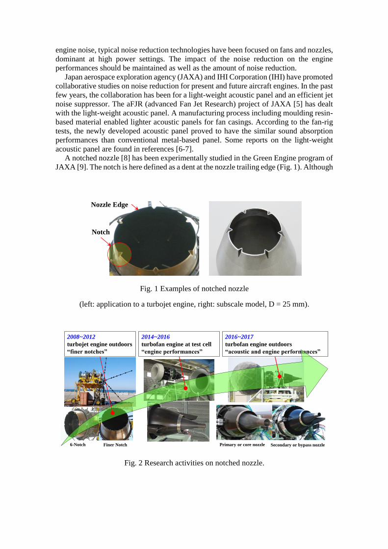
A notched nozzle [8] has been experimentally studied in the Green Engine program of
JAXA [9]. The notch is here defined as a dent at the nozzle trailing edge (Fig. 1). Although
Fig. 1 Examples of notched nozzle
(left: application to a turbojet engine, right: subscale model, D = 25 mm).
Fig. 2 Research activities on notched nozzle.
Notch
Nozzle Edge
6-Notch
2016~2017
turbofan engine outdoors
“acoustic and engine performances”
DGEN 380
Core Nozzle
Vent. DuctThrust Stand
ICD Tail ConeBypass Nozzle
2008~2012
turbojet engine outdoors
“finer notches”
2014~2016
turbofan engine at test cell
“engine performances”
Primary or core nozzle Secondary or bypass nozzleFiner Notch
the size of a notch is much smaller than the representative scale of nozzle, e.g., nozzle
diameter, disturbances due to the notch are sufficient to make the shear stress weaker and
suppress the jet noise emission. The small and simple structure of the notch is beneficial
to less thrust loss and less weight increase. Recent research activities on the notched
nozzle is presented in Fig. 2. The authors have improved the acoustic properties of this
mixing device and found that the finer and more notches with some modification of shape
would attain better noise reduction [10]. An eighteen notched nozzle installed on a
turbojet engine provided noise reduction up to 1.5 - 2 dB. To make the technical readiness
higher, it was needed to evaluate the acoustic properties of the notched nozzle under
practical co-axial nozzle configurations, typical of commercial aircraft engines. One
approach to fulfil the experimental requirements was to investigate the notched nozzles
with a high-bypass-ratio turbofan engine. Instead of full-scale engines, a subscale
turbofan engine, DGEN380 [11], was chosen for a series of noise tests. This paper
outlines the noise tests of the notched nozzles using the turbofan engine. The data in the
present report were obtained in the test campaign in 2017, and the corresponding serial
numbers are F162-F171. The serial numbers of F162-F164 were for core nozzle and those
of F166-F171 for bypass nozzle.
2. EXPERIMENT
2.1 Notched Nozzles
The original design involved larger notches equally located in the circumferential
direction of the nozzle. The revised version decreased the exit height by approximately
40% and accordingly increased the number of notches. This revision generate finer and
more disturbances over the entire area of the nozzle end. The resultant disturbances
contributed to suppressing the higher frequency noise as well as the broad band jet mixing
noise. The concept of this finer notch was reflected in the present design for the present
turbofan engine tests. The present design employed the less penetration angle of the notch
for better aerodynamic performances.
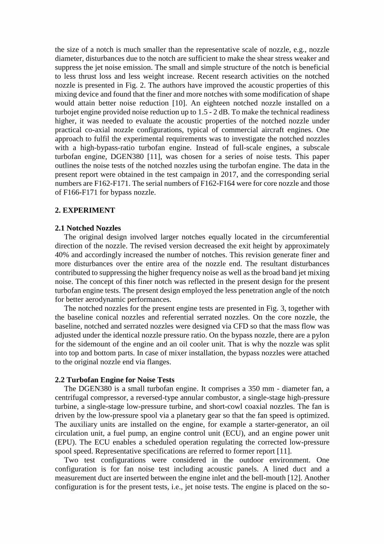
The notched nozzles for the present engine tests are presented in Fig. 3, together with
the baseline conical nozzles and referential serrated nozzles. On the core nozzle, the
baseline, notched and serrated nozzles were designed via CFD so that the mass flow was
adjusted under the identical nozzle pressure ratio. On the bypass nozzle, there are a pylon
for the sidemount of the engine and an oil cooler unit. That is why the nozzle was split
into top and bottom parts. In case of mixer installation, the bypass nozzles were attached
to the original nozzle end via flanges.
2.2 Turbofan Engine for Noise Tests
The DGEN380 is a small turbofan engine. It comprises a 350 mm - diameter fan, a
centrifugal compressor, a reversed-type annular combustor, a single-stage high-pressure
turbine, a single-stage low-pressure turbine, and short-cowl coaxial nozzles. The fan is
driven by the low-pressure spool via a planetary gear so that the fan speed is optimized.
The auxiliary units are installed on the engine, for example a starter-generator, an oil
circulation unit, a fuel pump, an engine control unit (ECU), and an engine power unit
(EPU). The ECU enables a scheduled operation regulating the corrected low-pressure
spool speed. Representative specifications are referred to former report [11].
Two test configurations were considered in the outdoor environment. One
configuration is for fan noise test including acoustic panels. A lined duct and a
measurement duct are inserted between the engine inlet and the bell-mouth [12]. Another
configuration is for the present tests, i.e., jet noise tests. The engine is placed on the so-
called floating stand that is mechanically suspended from the rigid stand via spring plates
[11, 13]. A load-cell unit underneath the floating stand receives the thrust by the engine.
In front of the bell-mouth is placed an inflow control device (ICD) or turbulence control
system (TCS), made of honeycomb panels. It breaks down the large-scale turbulences in
atmosphere and helps to stabilize the state of operation and prevent unexpected noise
from generating.
2.3 Data Acquisition
The jet noise measurement is viewed in Fig. 4. The engine stand was put on a rigid plate
in an apron zone of Shikabe airfield in Japan. The ECU referred to the atmospheric
temperature and regulated the low-pressure spool speed within the scheduled corrected
speed, NL. Here, the NL, e.g. 95 %, denotes the rate of power setting under standard state.
Typical sensors and locations inside and outside the engine are referred to former reports
[11, 13-14]. All these data of engine performances were stored at the sampling rate of 10
Hz and averaged over 45 - 60 seconds after all parameters saturated at each power setting.
Environmental conditions were also monitored and recorded. Depending on the wind
speeds, the confidence interval of the engine parameters suggested that mean values
existed within 1 %. The example of the engine performances, the corrected thrust, is
plotted in Fig. 5. The notched nozzles of the core and bypass sides as well as the serrated
nozzles kept the thrust similar to the baseline nozzles. Other parameters of the notched
nozzle, e.g., the mean exhaust velocities, the mass flow rate, the exhaust gas temperature,
and the fuel consumption, indicated no remarkable difference from the baseline nozzle at
95 % NL.
For the acoustic measurement, conventional measurement was carried out using 29
pressure-type microphones in the far-field arcs. The 20 m - arcs were centred by the
Fig. 3 Mixer nozzles used for the present noise tests.
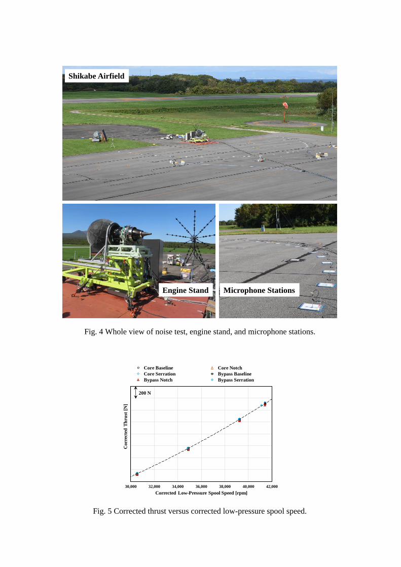
Fig. 4 Whole view of noise test, engine stand, and microphone stations.
Fig. 5 Corrected thrust versus corrected low-pressure spool speed.
Shikabe Airfield
Engine Stand Microphone Stations
30,000 32,000 34,000 36,000 38,000 40,000 42,000
Co
rrec
ted
Th
rust
[N
]
Corrected Low-Pressure Spool Speed [rpm]
Core Baseline Core Notch
Core Serration Bypass Baseline
Bypass Notch Bypass Serration
200 N
engine inlet and the nozzle exit. A microphone station has a 30 cm × 30 cm rigid plate,
an inversely installed quarter-inch microphone. The time signals of microphones are
simultaneously recorded for 30 seconds at the sampling rate of 50 kHz or 100 kHz. To
attenuate the influence of grazing wind around the microphones, a high-pass filter was
applied before the data recording system. Post-processing provides narrow band spectra,
one third octave band spectra, overall sound pressure levels within limited frequency
bands, and other acoustic indices. Correction regarding ground reflection at the
microphone station and air absorption was taken into account. The confidence interval of
the sound pressure levels was small enough at the concerning frequencies for jet noise,
here less than 2000 Hz.
Beam-forming with a phased array microphone system was applied in the noise tests.
As jet noise sources are not coherent, the conventional delay and sum (DAS) algorithm
provides relatively vague or low-resolution sources. One of the authors proposed
alternative algorithm as NNLS or CLEAN-SC instead of DAS [15-16] and showed better
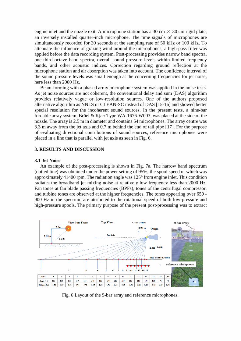
special resolution for the incoherent sound sources. In the present tests, a nine-bar
fordable array system, Brüel & Kjær Type WA-1676-W003, was placed at the side of the
nozzle. The array is 2.5 m in diameter and contains 54 microphones. The array centre was
3.3 m away from the jet axis and 0.7 m behind the end of tail pipe [17]. For the purpose
of evaluating directional contributions of sound sources, reference microphones were
placed in a line that is parallel with jet axis as seen in Fig. 6.
3. RESULTS AND DISCUSSION
3.1 Jet Noise
An example of the post-processing is shown in Fig. 7a. The narrow band spectrum
(dotted line) was obtained under the power setting of 95%, the spool speed of which was
approximately 41400 rpm. The radiation angle was 125° from engine inlet. This condition
radiates the broadband jet mixing noise at relatively low frequency less than 2000 Hz.
Fan tones at fan blade passing frequencies (BPFs), tones of the centrifugal compressor,
and turbine tones are observed at the higher frequencies. The tones appearing over 650 -
900 Hz in the spectrum are attributed to the rotational speed of both low-pressure and
high-pressure spools. The primary purpose of the present post-processing was to extract
Fig. 6 Layout of the 9-bar array and reference microphones.
reference microphone
9-bar array
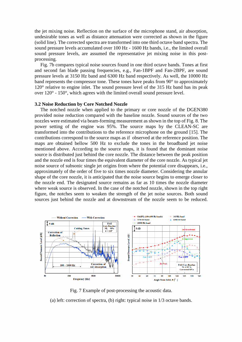
the jet mixing noise. Reflection on the surface of the microphone stand, air absorption,
undesirable tones as well as distance attenuation were corrected as shown in the figure
(solid line). The corrected spectra are transformed into one third octave band spectra. The
sound pressure levels accumulated over 100 Hz - 1600 Hz bands, i.e., the limited overall
sound pressure levels, are assumed the representative jet mixing noise in this post-
processing.
Fig. 7b compares typical noise sources found in one third octave bands. Tones at first
and second fan blade passing frequencies, e.g., Fan-1BPF and Fan-2BPF, are sound
pressure levels at 3150 Hz band and 6300 Hz band respectively. As well, the 10000 Hz
band represents the compressor tone. These tones have peaks from 90° to approximately
120° relative to engine inlet. The sound pressure level of the 315 Hz band has its peak
over 120° - 150°, which agrees with the limited overall sound pressure level.
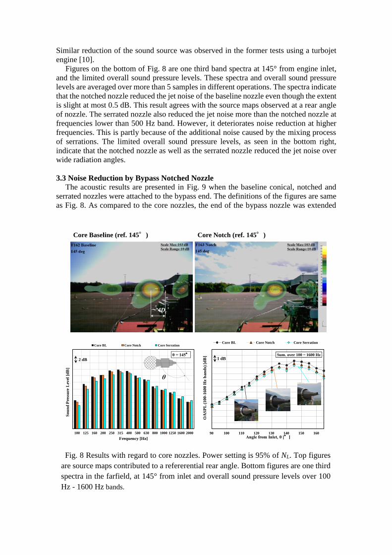
3.2 Noise Reduction by Core Notched Nozzle
The notched nozzle when applied to the primary or core nozzle of the DGEN380
provided noise reduction compared with the baseline nozzle. Sound sources of the two
nozzles were estimated via beam-forming measurement as shown in the top of Fig. 8. The
power setting of the engine was 95%. The source maps by the CLEAN-SC are
transformed into the contributions to the reference microphone on the ground [15]. The
contributions correspond to the source maps as if observed at the reference position. The
maps are obtained bellow 500 Hz to exclude the tones in the broadband jet noise
mentioned above. According to the source maps, it is found that the dominant noise
source is distributed just behind the core nozzle. The distance between the peak position
and the nozzle end is four times the equivalent diameter of the core nozzle. As typical jet
noise source of subsonic single jet origins from where the potential core disappears, i.e.,
approximately of the order of five to six times nozzle diameter. Considering the annular
shape of the core nozzle, it is anticipated that the noise source begins to emerge closer to
the nozzle end. The designated source remains as far as 10 times the nozzle diameter
where weak source is observed. In the case of the notched nozzle, shown in the top right
figure, the notches seem to weaken the strength of the jet noise sources. Both sound
sources just behind the nozzle and at downstream of the nozzle seem to be reduced.
Fig. 7 Example of post-processing the acoustic data.
(a) left: correction of spectra, (b) right: typical noise in 1/3 octave bands.
Similar reduction of the sound source was observed in the former tests using a turbojet
engine [10].
Figures on the bottom of Fig. 8 are one third band spectra at 145° from engine inlet,
and the limited overall sound pressure levels. These spectra and overall sound pressure
levels are averaged over more than 5 samples in different operations. The spectra indicate
that the notched nozzle reduced the jet noise of the baseline nozzle even though the extent
is slight at most 0.5 dB. This result agrees with the source maps observed at a rear angle
of nozzle. The serrated nozzle also reduced the jet noise more than the notched nozzle at
frequencies lower than 500 Hz band. However, it deteriorates noise reduction at higher
frequencies. This is partly because of the additional noise caused by the mixing process
of serrations. The limited overall sound pressure levels, as seen in the bottom right,
indicate that the notched nozzle as well as the serrated nozzle reduced the jet noise over
wide radiation angles.
3.3 Noise Reduction by Bypass Notched Nozzle
The acoustic results are presented in Fig. 9 when the baseline conical, notched and
serrated nozzles were attached to the bypass end. The definitions of the figures are same
as Fig. 8. As compared to the core nozzles, the end of the bypass nozzle was extended
Fig. 8 Results with regard to core nozzles. Power setting is 95% of NL. Top figures
are source maps contributed to a refererential rear angle. Bottom figures are one third
spectra in the farfield, at 145° from inlet and overall sound pressure levels over 100
Hz - 1600 Hz bands.
Core Baseline (ref. 145°)
~ 4Dc
Core Notch (ref. 145°)
100 125 160 200 250 315 400 500 630 800 1000 1250 1600 2000
Sou
nd
Pre
ssu
re L
evel
[d
B]
Frequency [Hz]
θ = 145°
Core BL Core Notch Core Serration
2 dB
θ
90 100 110 120 130 140 150 160
OA
SP
L (
10
0-1
60
0 H
z b
an
ds)
[d
B]
Angle from Inlet, θ [°]
Sum. over 100 ~ 1600 Hz
Core BL Core Notch Core Serration
1 dB
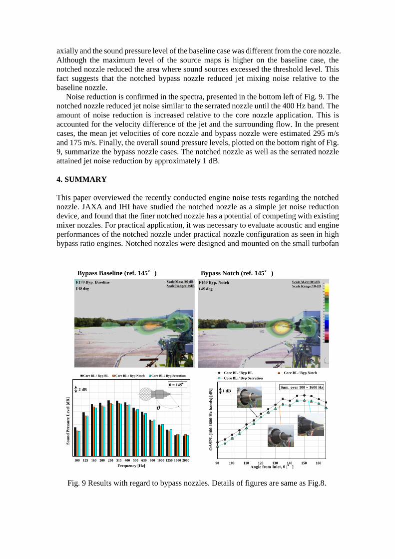
axially and the sound pressure level of the baseline case was different from the core nozzle.
Although the maximum level of the source maps is higher on the baseline case, the
notched nozzle reduced the area where sound sources excessed the threshold level. This
fact suggests that the notched bypass nozzle reduced jet mixing noise relative to the
baseline nozzle.
Noise reduction is confirmed in the spectra, presented in the bottom left of Fig. 9. The
notched nozzle reduced jet noise similar to the serrated nozzle until the 400 Hz band. The
amount of noise reduction is increased relative to the core nozzle application. This is
accounted for the velocity difference of the jet and the surrounding flow. In the present
cases, the mean jet velocities of core nozzle and bypass nozzle were estimated 295 m/s
and 175 m/s. Finally, the overall sound pressure levels, plotted on the bottom right of Fig.
9, summarize the bypass nozzle cases. The notched nozzle as well as the serrated nozzle
attained jet noise reduction by approximately 1 dB.
4. SUMMARY
This paper overviewed the recently conducted engine noise tests regarding the notched
nozzle. JAXA and IHI have studied the notched nozzle as a simple jet noise reduction
device, and found that the finer notched nozzle has a potential of competing with existing
mixer nozzles. For practical application, it was necessary to evaluate acoustic and engine
performances of the notched nozzle under practical nozzle configuration as seen in high
bypass ratio engines. Notched nozzles were designed and mounted on the small turbofan
Fig. 9 Results with regard to bypass nozzles. Details of figures are same as Fig.8.
Bypass Baseline (ref. 145°) Bypass Notch (ref. 145°)
100 125 160 200 250 315 400 500 630 800 1000 1250 1600 2000
So
un
d P
ress
ure
Lev
el [
dB
]
Frequency [Hz]
θ = 145°
Core BL / Byp BL Core BL / Byp Notch Core BL / Byp Serration
2 dB
θ
90 100 110 120 130 140 150 160
OA
SP
L (
10
0-1
600 H
z b
an
ds)
[d
B]
Angle from Inlet, θ [°]
Sum. over 100 ~ 1600 Hz
Core BL / Byp BL Core BL / Byp Notch
Core BL / Byp Serration
1 dB
engine, DGEN380. According to the noise tests, it is concluded that the notched nozzle,
if the corrected thrust and other engine parameters were well adjusted to the baseline
nozzle, would have a slight noise margin up to 1 dB. Considering the superiority of
notched nozzle in its simple structure, lighter weight, and less impact on engine
performances, the notched nozzle has a potential of application to the existing engines as
well as the new types of engines in order to gain more noise margin with minimizing the
impact on engine performances.
5. REFERENCES
[1] Gregg G. Fleming, et al., “Environmental Trends in Aviation to 2050”, ICAO
Environmental Report 2016, (2016).
[2] ICAO Secretary, “Reducing Aircraft Noise - Overview”, ICAO Environmental
Report 2016, (2016).
[3] Harvey H. Hubbard, “Aeroacoustics of Flight Vehicles: Theory and Practice”,
NASA RP-1258, Vol.2 (1991).
[4] D. Casalino, et al., “Aircraft Noise Reduction Technologies; A Bibliographic
Review”, Aerospace Science and Technology, Vol,12-1, pp.1-17, (2008).
[5] Toshio Nishizawa, “JAXA’s R&D Project: Advanced Fan Jet Research (aFJR)”,
Gas Turbine Society of Japan Annual Meeting (S-3), in Japanese, (2018).
[6] Tsutomu Oishi, et al., “Development of All Plastic Acoustic Liner under aFJR
Project”, Green Aviation 2016, Nr.125, (2016).
[7] Mai Sakamoto, et al., “Development of Lightweight Sound-Absorbing Liner for
aFJR Project”, Gas Turbine Society of Japan Annual Meeting (A-4), in Japanese,
(2018).
[8] Tsutomu Oishi, “Jet Noise Reduction by Notched Nozzle on Japanese ECO-Engine
Project”, AIAA-2010-4026, (2010).
[9] Tatsuya Ishii, et al., “Acoustic Research Programs in Aircraft Engines in JAXA:
aFJR and Green Engine”, Asia-Pacific Joint Conference on Propulsion and Power,
Nr.131, (2016).
[10] Tatsuya Ishii, et al., “Outdoor Noise Test of Revised Notched Nozzle”, Internoise-
2012, Nr.706, (2012).
[11] Tatsuya Ishii, et al., “Preliminary Test of Turbofan Engine for Noise Research”,
International Gas Turbine Congress, Nr.188, (2015).
[12] Kenichiro Nagai, et al., “Acoustic Liner Test of DGEN380 Turbofan Engine”,
Internoise-2019, (2019).
[13] Tatsuya Ishii, et al., “Noise of Small Turbofan Engine DGEN380”, International
Society of Air-Breathing Engine, Nr.22545, (2017).
[14] Tatsuya Ishii, et al., “Experimental Study on Acoustic Performances of Notched
Nozzle Using a Subscale Turbofan Engine”, ASME GT2018-76713, (2018).
[15] Jorgen Hald, et al., “Mapping of Contributions from Car-exterior Aerodynamic
Sources to an In-cabin Reference Signal Using CLEAN-SC”, Internoise-2016, (2016).
[16] Yutaka Ishii, et al., “Application of Beam-forming Using Deconvolution Method to
the Development of the New Launch Pad of Epsilon”, Berlin Beamforming Conference,
D13, (2016).
[17] Tatsuya Ishii, et al., “Noise Measurement of Small Turbofan Engine with Notched
Nozzle for Jet Noise Reduction”, AIAA-2018-3611, (2018).