Embed Size (px)
Citation preview
Jeff Nicol Style Wood Turning Steady Rest By JD Combs 11/03/10
I promised Creeker Jim Sebring a tutorial on my new Jeff Nicol style steady rest. I had indicated in a previous thread on the creek that I was going to try to make one myself even though I don’t have a welder. Well I did sort of!
Getting started: A listing of the tools I used:
- Drill Press and set of HSS bits. (1/4” 5/16” 3/8” and 13/32” bits are all that is needed) - A no 7 drill bit (0.201”) optional - A Q letter drill bit (0.332”) optional - A 60* counter sink bit for metal - 1/4” and 3/8” thread taps (not absolutely necessary, just drill through and use nuts) - Machinist Vise (any good bench vise will do) - Straight edge and square - A reciprocating saw (commonly referred to as a saws-all. - Dremel with small stone grinder. (or similar de-burring tool or files) - Stationary belt sander. (also for de-burring) - Various wrenches for 1/4”, 5/16” and 3/8” bolts/nuts. - A couple of 4” c-clamps (small 6” Irwin quick clamps will do) - A wooden corner jig for drill press. (see photos) - Temporary fasteners (I used 1/4-20 and 3/8-16 carriage bolts)
The Materials List: - Flange Angle Ring w/holes (diameter should be a least the same as your lathe swing)
• Mine was 2” over my lathe swing or 18”. I wanted to make sure I full diameter capacity; however, I later found out that a 16” would have worked fine.
• Find it at http://www.mcmaster.com/#angle-rings/=9jtkip add $10 for shipping. - 15 inches of 1-1/4” x 1/8” wall square steel tubing (Add 5” if you add the optional
platter steady) - 4ft of 1” x 3/16” wall square steel tubing (Add 8” if you add the optional platter steady) - 4ea. 4 prong knob with 3/8" x 16 x 3/4" stud (EBay Item # 310241352713)
• Or make your own t-handles from 3/8" x 16 bolts. - 4ea. Skate Wheels - Blue Blank 72mm 78A Inline indoor Skate Wheels +ABEC 9
bearings (EBay Item # 360311682163) • This item is a package of eight, you can find 4 and other colors if you look.
Make sure they indicate that they come with bearings. You will need six if you add the platter rest.
- 4ea. 5/16-18 bolts for axles (I used carriage bolts with the square shoulder removed. Not necessary unless you like a neat “hub-cap”. Add two with the platter steady)
- 4ea. 5/16 lock washers for axles. (Add two with the platter steady) - 8ea. 5/16-18 nuts for the axles. (Add four with the platter steady) - 4ea. 3/8-16 nuts for clamp knobs. Welded in place. (Add one with the platter steady) - 4ea. 1/4-20 x ½” socket head counter sunk screws. - 1ea. 1/4-20 x 1” socket head counter sunk screws w/nut and flat washer. (If you add
the platter steady) - 1ea. 5/16” x 4” x 13-5/16” flat stock (ring mounting base plate) - 2ea. 1/4” x 1-3/4” x 4” flat stock (ring mounting base plate and clamp guide tenons) - 1ea. 5/16” x 2-1/2” x 4” flat stock (ring mounting base clamp plate)
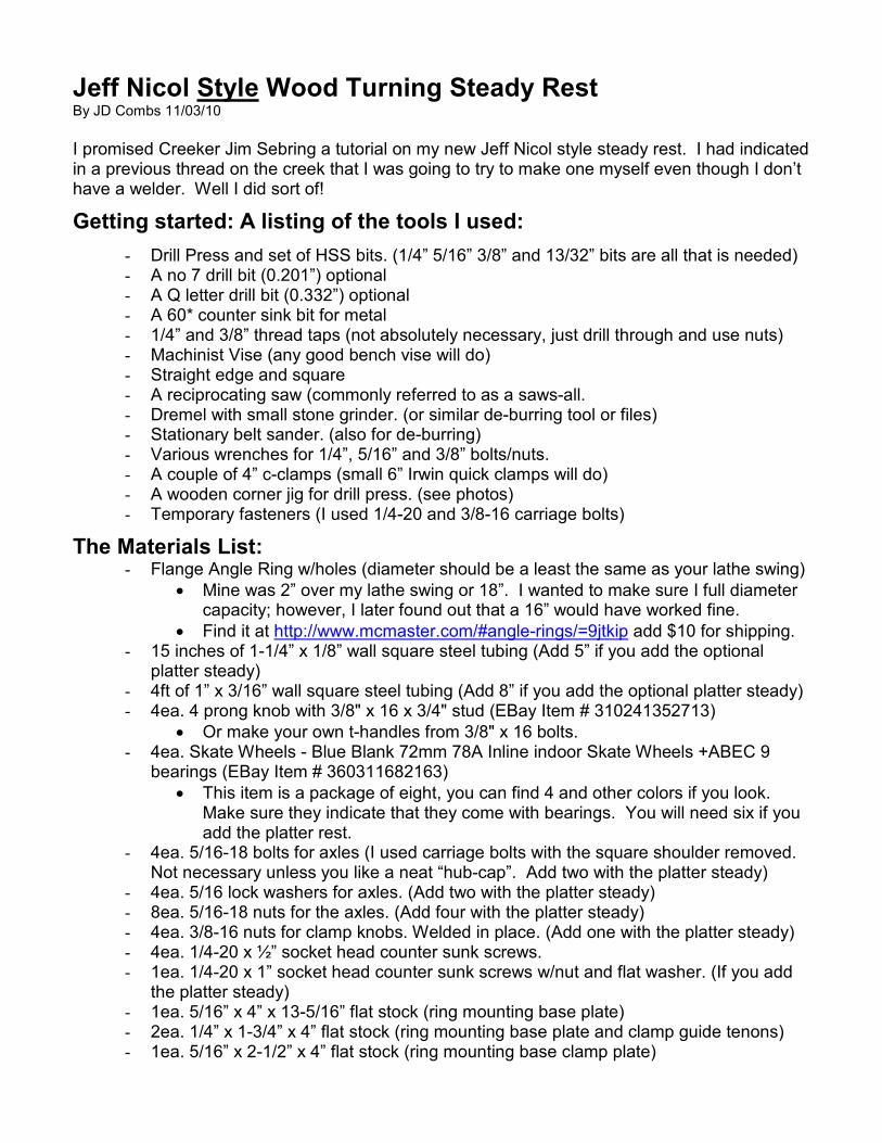
Dimensioned drawing.

How I did it: (Note a title (~) before a number = approximately)
Initial Preparation
- Material - Paper Towels and Mineral Spirits (or equivalent solvent) Wipe down all the metal components (ring and tubes) with solvent and dry thoroughly with towels. These components especially the tubes come coated with a black oxide and will get all over everything including you if you don’t clean it off first. Section 1. Making The Wheel Support Tubes
- Material - 1” x 3/16” wall square steel tubing
Using the saws-all cut the 1” tubing into two pieces each 24” long. Layout the center of each 24” piece so that it can be cut at the center at a ~45* angle giving you 4 wheel support tubes with an angle on one end.
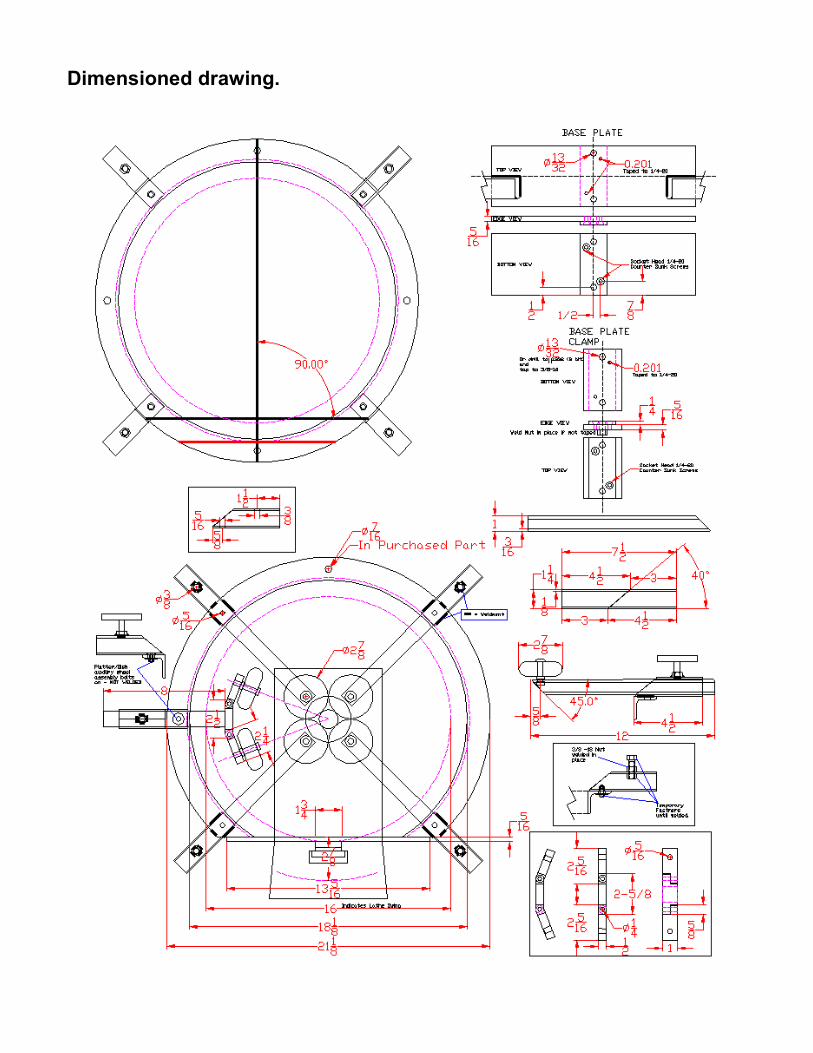
Set up your drill press with a corner jig. (I used my cross slide vice to hold the jig but it can simply be clamped to the drill table.)
Layout the location of a 5/16 hole in the angled end of one of the wheel support tubes 5/8” from the end of the angled cut.
Clamp the marked tube to your jig and clamp the jig in location and drill the 5/16 hole. Unclamp the tube leaving the jig in position. Clamp and drill 5/16 holes in the remaining 3 support tubes. The jig will locate the hole for the remaining support tubes.

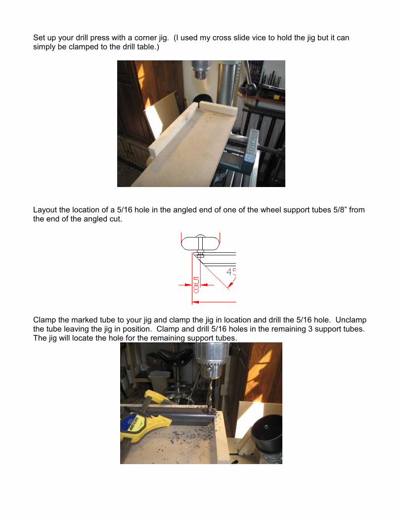
Take the 4 support tubes to the belt sander and sand off all sharp burrs, corners, and edges. Then using your Dremel or round file, de-burr the inside edges of the tube and the hole. Note the rounded outside edges from the sander. Make sure you do both ends of each tube. You are done with the support tubes for now, set them aside until later.
Section 2. Making The Wheel Support Clamping Guides
- Material - 1-1/4” x 1/8” wall square steel tubing Using the saws-all cut the 1-1/4” tubing into two pieces ~7-1/5”. The length is not critical so you can count the saw blade kerfs as part of your length. Now layout the center of the pieces so that they can be cut at the center at ~40*. Tip: Measuring and marking 4.5” and 3” on both sides but from opposite ends and connecting the marks in the center will give you a cut line of about 40*. Cut both of the 7.5” pieces to give you 4 clamp tubes each ~4.5” long with one end cut at an angle.

The clamp tubes will require two holes drilled in them. Layout the location of a 3/8” hole in the center of the short side of one of the clamp tubes. It will be about 1-1/2” from the end of the straight cut end. Layout the location of a 5/16” hole in the angled end of one of the clamp tubes 5/8” from the end of the angled cut.
Setup your drill jig and drill the 3/8” hole in the marked clamp. Place the remaining clamp tubes in the jig and drill the 3/8” hole in them. Reset the drill jig and drill the 5/16” hole in the marked clamp tube. Place the remaining clamp tubes in the jig and drill the 5/16” hole in them.
Take the 4 clamp tubes to the belt sander and sand off all sharp burrs, corners, and edges. Using your Dremel or round file, de-burr the inside edges of the tube and the holes.
Note the rounded outside edges from the sander. Make sure you do both ends of each tube. Then using your Dremel or round file, de-burr the inside edges of the tube and the holes.
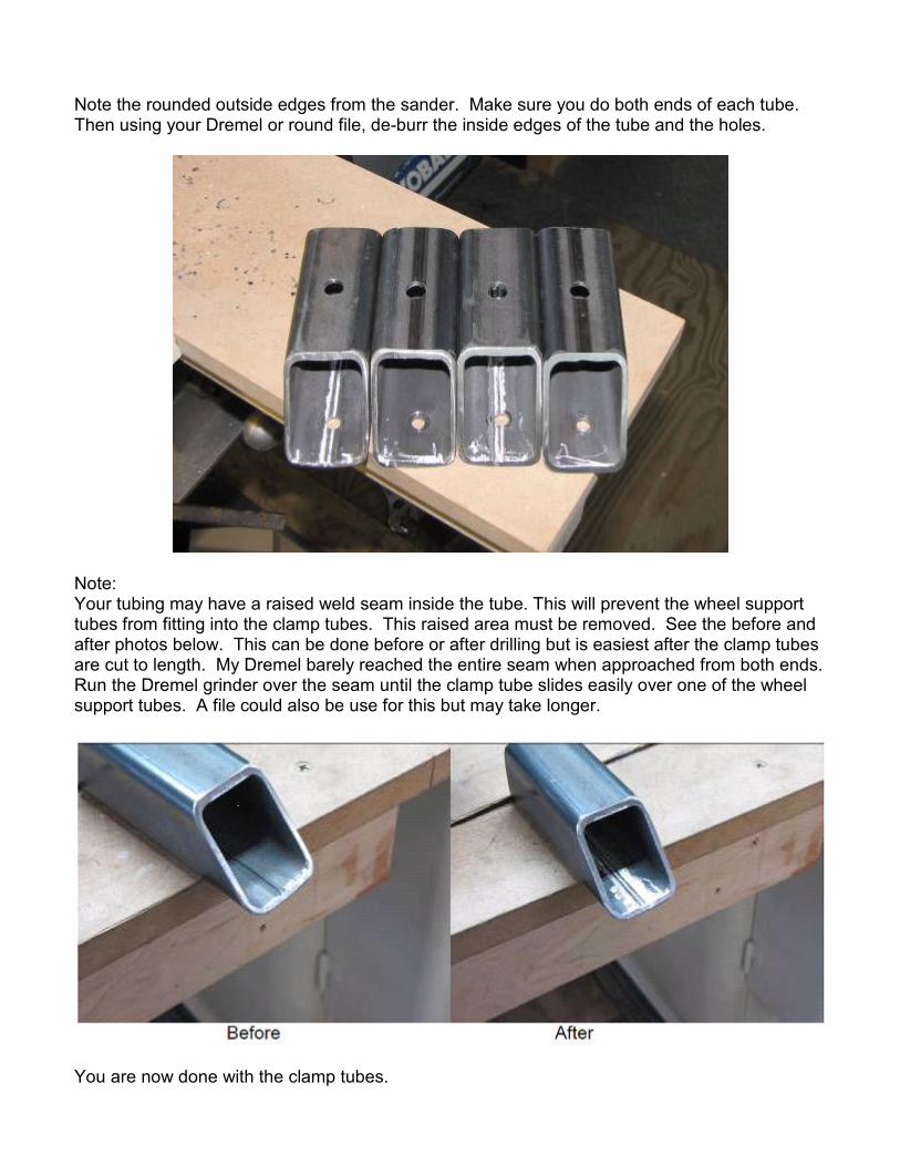
Note: Your tubing may have a raised weld seam inside the tube. This will prevent the wheel support tubes from fitting into the clamp tubes. This raised area must be removed. See the before and after photos below. This can be done before or after drilling but is easiest after the clamp tubes are cut to length. My Dremel barely reached the entire seam when approached from both ends. Run the Dremel grinder over the seam until the clamp tube slides easily over one of the wheel support tubes. A file could also be use for this but may take longer.
You are now done with the clamp tubes.

Section 3. Preparing the Ring
- Material - 18” Flange Angle Ring with holes (diameter should be a least the same as your lathe swing)
Using the “temporary fasteners” noted in the tools listing section assemble the four clamp tubes to the ring and assemble the 3/8” nuts from the materials section using temporary bolts and an extra nut inside the tube. These do not have to be tight just snug enough to hold the outside nut in location. Any 1” or longer 3/8-16 bolt will do. As pictured below I used 2” carriage bolts I had on hand.
Use a good straight edge to make sure the clamp tubes line up properly. They should be perpendicular to the circumference of the ring. Tighten the temporary bolts that hold the tube to the ring securely. Make note of the location of the ring weld seam where the ring ends are welded together. (red arrow) This will be close to the bottom of the ring. The hole next to it will be the exact bottom of the ring. Using the bottom hole and the exact top hole (blue arrow) layout a cut line along the bottom of the ring for the ring mounting plate.
The following drawing shows how to layout the cut line.

I used a straight edge and a square to mark the “My cut line” shown below.
After the line is marked loosen and swing the bottom two clamp tubes out of the way. I clamped a straight edge to the bottom two clamp tubes to give me a visual reference line parallel to the cut line. Clamp the ring in a vise and using the saws-all cut the ring at the marked line. Note that the cut line is positioned so that the center of the ring is centered on your lathe spindle center. (The drill press prevented me from clamping my ring so that the cut was vertical. Vertical would have made it easier but I managed.)
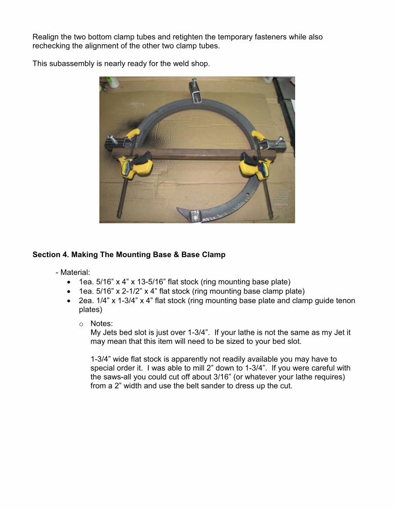
Realign the two bottom clamp tubes and retighten the temporary fasteners while also rechecking the alignment of the other two clamp tubes. This subassembly is nearly ready for the weld shop.
Section 4. Making The Mounting Base & Base Clamp
- Material: • 1ea. 5/16” x 4” x 13-5/16” flat stock (ring mounting base plate) • 1ea. 5/16” x 2-1/2” x 4” flat stock (ring mounting base clamp plate) • 2ea. 1/4” x 1-3/4” x 4” flat stock (ring mounting base plate and clamp guide tenon
plates)
o Notes: My Jets bed slot is just over 1-3/4”. If your lathe is not the same as my Jet it may mean that this item will need to be sized to your bed slot.
1-3/4” wide flat stock is apparently not readily available you may have to special order it. I was able to mill 2” down to 1-3/4”. If you were careful with the saws-all you could cut off about 3/16” (or whatever your lathe requires) from a 2” width and use the belt sander to dress up the cut.

I purchased most of the above base plate and base clamp parts in the lengths indicated from a local metal supplier so very little cutting was required other then the noted milling of the 2” part. To prepare the precut parts: Layout the 5/16” x 4” x 13-5/16” (the length of your base plate may vary if your ring ID matches your lathe swing) base plate to find it’s center across it’s length. Layout two 13/32” hole locations along this center line and two 0.201 (no 7 bit) holes per the indicated locations. The 0.201 holes in the base plate will be taped to ¼-20. The same holes in the guide tenon plate will be counter bored for 1/4-20 x ½” socket head counter sunken screw heads.

The base plate clamp is prepared almost identically to the base plate except that it is upside down as compared to the base plate. All dimensions except the length (left to right in drawing) are the same as the base plate. The biggest difference is that the 13/32 holes are optionally taped to 3/8-16 (drilled to 0.332 if taped) or a 3/8-16 nut can be welded to the bottom side after drilling to 13/32.
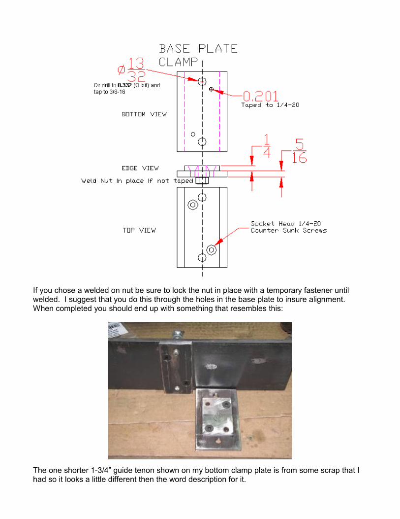
If you chose a welded on nut be sure to lock the nut in place with a temporary fastener until welded. I suggest that you do this through the holes in the base plate to insure alignment. When completed you should end up with something that resembles this:
The one shorter 1-3/4” guide tenon shown on my bottom clamp plate is from some scrap that I had so it looks a little different then the word description for it.

The four holes were already present and it was shorter then the 4 inches but it still works fine. You are about ready to visit the weld shop. You have found one right? Maybe a good neighbor down the street owns a welder. At any rate you are about ready to head out to one. The last thing you need to do for welding prep is to scribe a center line on the top side of the base plate to locate the ends of the ring when it is welded on. The flat side of the ring should align along this line. The opening (or cut area) of the ring should be centered left to right. This was the only weld that had to be held in position during my weld up. I could have and I recommend that you put a couple of temporary angle brackets at locations “A” and “B”. They could be made from 1” long pieces of 1” angle iron or they could be picked up in the hardware department of your local BORG. In my case I actually picked this plate up at the welder who is also my metal supplier when I went to get the welding done. I did all the above drilling and taping with the ring attached, NOT recommended.
Now grab the ring with the guide tubes and nuts attached, the base plate if not already attached to the ring and the base plate clamp if you are using welded on nuts on it and head out to the welder of choice. When you get to the welder be sure to instruct him to make sure he welds all the around any welded nuts. I had one pop off right after I got it home. When he welds the “end” welds you could just have him continue welding around the brackets. They will add support once welded in place. Or you could remove them after the ring is tacked in place if you prefer a cleaner look. Just have him stop after an initial tack weld and then remove the temporary angle brackets and then let him continue welding as indicated.
“A” “B”

When you get the welded assembly home you should have something that resembles these photos.
Section 5. Assembling the wheels (lets put it together)
- Material: • Skate Wheels - Blue Blank 72mm 78A Inline indoor Skate Wheels +ABEC 9
bearings or other of your choice. (BTW the larger the ABEC number the better the bearing)
• 5/16-18 bolts for axils • 5/16-18 nuts for the axles • 5/16 lock washers for axles • Wheel Support Tubes from Section 1.
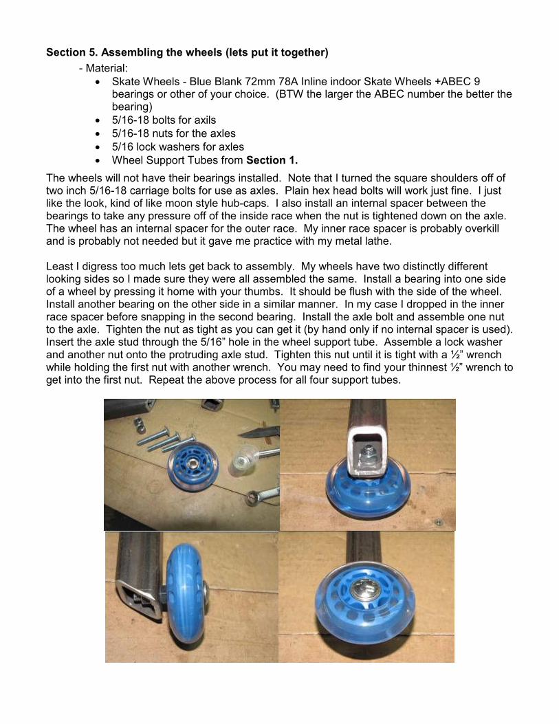
The wheels will not have their bearings installed. Note that I turned the square shoulders off of two inch 5/16-18 carriage bolts for use as axles. Plain hex head bolts will work just fine. I just like the look, kind of like moon style hub-caps. I also install an internal spacer between the bearings to take any pressure off of the inside race when the nut is tightened down on the axle. The wheel has an internal spacer for the outer race. My inner race spacer is probably overkill and is probably not needed but it gave me practice with my metal lathe. Least I digress too much lets get back to assembly. My wheels have two distinctly different looking sides so I made sure they were all assembled the same. Install a bearing into one side of a wheel by pressing it home with your thumbs. It should be flush with the side of the wheel. Install another bearing on the other side in a similar manner. In my case I dropped in the inner race spacer before snapping in the second bearing. Install the axle bolt and assemble one nut to the axle. Tighten the nut as tight as you can get it (by hand only if no internal spacer is used). Insert the axle stud through the 5/16” hole in the wheel support tube. Assemble a lock washer and another nut onto the protruding axle stud. Tighten this nut until it is tight with a ½” wrench while holding the first nut with another wrench. You may need to find your thinnest ½” wrench to get into the first nut. Repeat the above process for all four support tubes.
Section 6. Install The Support Arms and Test
- Material: • The assemble unit
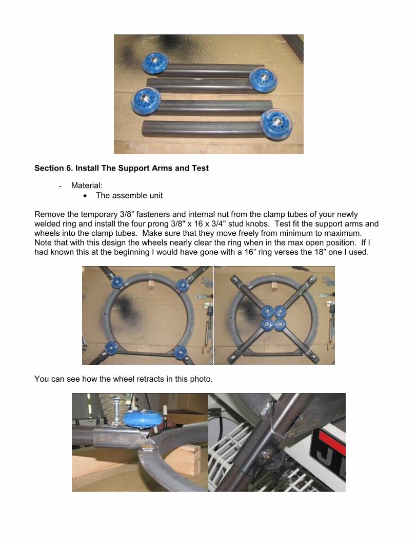
Remove the temporary 3/8” fasteners and internal nut from the clamp tubes of your newly welded ring and install the four prong 3/8" x 16 x 3/4" stud knobs. Test fit the support arms and wheels into the clamp tubes. Make sure that they move freely from minimum to maximum. Note that with this design the wheels nearly clear the ring when in the max open position. If I had known this at the beginning I would have gone with a 16” ring verses the 18” one I used.
You can see how the wheel retracts in this photo.
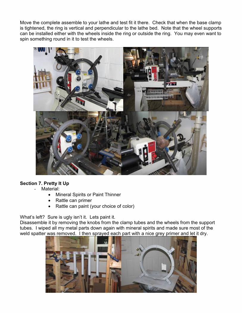
Move the complete assemble to your lathe and test fit it there. Check that when the base clamp is tightened, the ring is vertical and perpendicular to the lathe bed. Note that the wheel supports can be installed either with the wheels inside the ring or outside the ring. You may even want to spin something round in it to test the wheels.
Section 7. Pretty It Up
- Material: • Mineral Spirits or Paint Thinner • Rattle can primer • Rattle can paint (your choice of color)
What’s left? Sure is ugly isn’t it. Lets paint it. Disassemble it by removing the knobs from the clamp tubes and the wheels from the support tubes. I wiped all my metal parts down again with mineral spirits and made sure most of the weld spatter was removed. I then sprayed each part with a nice grey primer and let it dry.

The next day I sprayed it a nice gloss white and reassembled everything.
Now, if you have done everything that I have described in this process you will have a similar wood turning steady rest as pictured above so now get to work turning some bowls and hollow forms. If you decide to add the platter steady you should be able to get all the info you need from the drawing and the photos. There are a few close up photos of the platter steady on the next page.
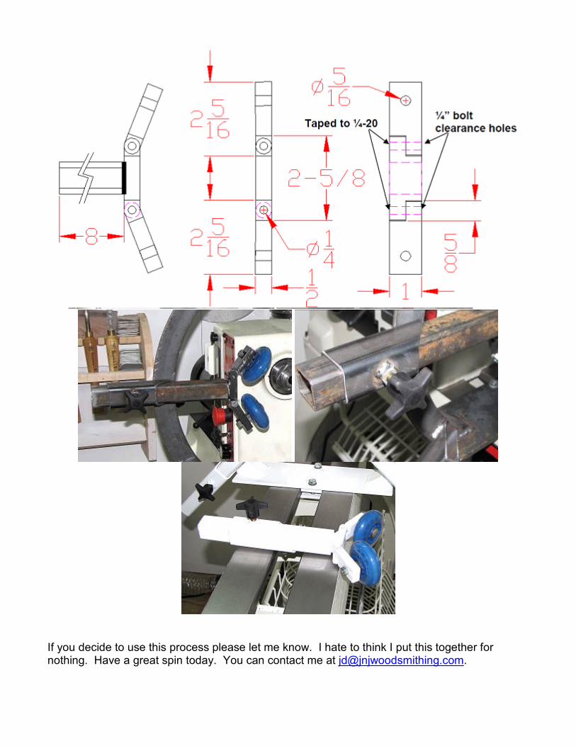
If you decide to use this process please let me know. I hate to think I put this together for nothing. Have a great spin today. You can contact me at [email protected].