Embed Size (px)
Citation preview
Application Report SPRABW1 – April 2014
1
How to Develop a Project With TI SYS/BIOS Jeanne Yi MCU SAE Team
ABSTRACT
TI SYS/BIOS is a real-time operating system kernel. It is also a component of TI RTOS. TI RTOS is an integration system; it includes TI SYS/BIOS kernel, XDCtools, middleware, MCU driver library, and other kinds of components. TI-RTOS is a one-stop solution for developing applications for TI embedded processors and is tightly integrated with TI’s Code Composer Studio™ (CCS) development environment. TI-RTOS also provides many example project packages with which you may start to develop a project with TI SYS/BIOS.
Contents Overview ............................................................................................................................................... 3 1 Preparation ................................................................................................................................... 4
1.1 System Requirements ............................................................................................................ 4 1.2 Download the Installation Packages ....................................................................................... 4 1.3 Installing CCS 5.1.1.00031, SYS/BIOS 6.33.4.39, and XDCtools 3.23.4.27 ............................ 4
2 Create Your First SYS/BIOS Project ............................................................................................ 5 2.1 Startup Code Composer Studio .............................................................................................. 5 2.2 Create a SYS/BIOS CCS Project ............................................................................................ 5 2.3 Link the Memory Map File for the Project ................................................................................ 7 2.4 Build the Project ..................................................................................................................... 9 2.5 Debug the Project ................................................................................................................. 10 2.6 For More Reference .............................................................................................................. 11
3 Use of the Basic Components for a SYS/BIOS Project ............................................................ 11 3.1 Use .cfg File to Configure the System .................................................................................. 11 3.2 Entrance of the System ........................................................................................................ 13 3.3 Dynamically or Statically Create the Task ............................................................................. 14
3.3.1 Dynamically Creating the Task .................................................................................. 14 3.3.2 Statically Creating the Task ....................................................................................... 14
3.4 Usage of the Semaphores .................................................................................................... 16 3.5 Use of the Mailboxes ............................................................................................................ 17
3.5.1 Introduction About the Mailboxes .............................................................................. 17 3.5.2 Use Mailboxes in Your Project .................................................................................. 17 3.5.3 Often-used SYS/BIOS API Function for Mailbox ....................................................... 18
3.6 Use of the Hwi Tasks ............................................................................................................ 19 3.6.1 Introduction to the Hwi............................................................................................... 19 3.6.2 Add Hwi Module in Your Project ................................................................................ 19 3.6.3 An Hwi Instance Example Based on Concerto™ F28M35x ....................................... 20
References.......................................................................................................................................... 23

SPRABW1
2 How to Develop a Project With TI SYS/BIOS
Figures Figure 1. Folders in the Directory c:\ti ................................................................................................ 4 Figure 2. CCS 5.1 Welcome Display ................................................................................................... 5 Figure 3. CCS Workspace Launcher ................................................................................................... 5 Figure 4. New CCS Project .................................................................................................................. 6 Figure 5. RTSC Configuration Settings for the SYS/BIOS Project .................................................... 7 Figure 6. General Setting for the Project ............................................................................................ 8 Figure 7. CCS Project Explorer Window ............................................................................................. 9 Figure 8. CCS Console Window ........................................................................................................ 10 Figure 9. CCS Problems Window ...................................................................................................... 10 Figure 10. ccxml File Edit Window .................................................................................................... 10 Figure 11. CCS Debug Window ......................................................................................................... 11 Figure 12. XDCtools GUI Window (SYS/BIOS System Component Overview) .............................. 12 Figure 13. XDCtools GUI Window (SYS/BIOS Runtime Options) .................................................... 12 Figure 14. XDCtools GUI Window (Task Thread Management) ....................................................... 15 Figure 15. XDCtools GUI Window (Script Source Code for Task) .................................................. 15 Figure 16. XDCtools GUI Window (Semaphore Management) ........................................................ 17 Figure 17. XDCtools GUI Window (Script Source Code for Semaphore) ....................................... 17 Figure 18. Selection of Synchronization Modules ........................................................................... 17 Figure 19. XDCtools GUI Window (Mailbox Module Settings)......................................................... 18 Figure 20. XDCtools GUI Window (Mailbox Instance Settings) ....................................................... 18 Figure 21. XDCtools GUI Window (Hardware Interrupt Module Settings) ...................................... 20 Figure 22. XDCtools GUI Window (Hardware Interrupt Instance Settings) .................................... 21 Figure 23. Interrupt 0 to 91 Priority (PRI0 to PRI22) Registers ........................................................ 22
Tables Table 1. Devices Supported by TI-RTOS and TI SYS/BIOS ......................................................... 3 Table 2. Interrupts from NVIC to Cortex-M3 ............................................................................... 21 Table 3. Peripherals Register Map .............................................................................................. 22 Table 4. Interrupt 0 to 91 Priority (PRI0 to PRI22) Registers Field Descriptions ..................... 22

SPRABW1
How to Develop a Project With TI SYS/BIOS 3
Overview TI-RTOS is a real-time operating system for TI devices. The first released package of TI-RTOS was MCU-SDK V1.00.00.68. The most recent released package is TI-RTOS 1.21.00.19. TI-RTOS facilitates the development of applications for TI microcontrollers. This product contains several software components and examples. The components include
• SYS/BIOS
• IPC
• MWare
• NDK
• StellarisWare
• UIA
• XDCtools
The examples within TI-RTOS have used the software components together.
TI SYS/BIOS is the real-time OS kernel of TI-RTOS. TI SYS/BIOS is a scalable real-time kernel designed for applications that require real-time scheduling and synchronization or real-time instrumentation. TI SYS/BIOS provides preemptive multithreading, hardware abstraction, real-time analysis, and configuration tools. TI SYS/BIOS is designed to minimize memory and CPU requirements on the target. It must be used together with the proper version of XDCtools.
The devices dctsupported by SYS/BIOS include MSP430™ MCUs, F28M35X, TM4C MCUs, and AM335X. The devices supported by TI-RTOS only include F28M35X and TM4C MCUs. Table 1 lists the devices supported by TI-RTOS and TI SYS/BIOS. (For more details, see on the website http://www.ti.com/lsds/ti/tools-software/rtos.page#support.)
Table 1. Devices Supported by TI-RTOS and TI SYS/BIOS
MSP430 MCUs F28M35x TM4C AM335x
TI-RTOS Yes Yes
SYS/BIOS kernel
Yes Yes Yes Yes
This document primarily discusses how to use the basic elements of SYS/BIOS, such as tasks, semaphores, mailboxes, Hwi, and so forth, together with the CCS and XDCtools to develop a project. SYS/BIOS 6.33.4.39 is the version we used. We used the F28M35x device and we worked only with its Cortex™-M3 MCU core.
For more training detail about SYS/BIOS, download the reference resource from www.ti.com. If you have questions when developing your project, we strongly recommend that you to raise your questions on the BIOS forum of TI’s E2E Community: http://e2e.ti.com/support/embedded/bios/f/355.aspx or on the Chinese technical support forum http://www.deyisupport.com.

SPRABW1
4 How to Develop a Project With TI SYS/BIOS
1 Preparation
1.1 System Requirements
We used is Windows 7™, but Windows Vista or Windows XP (SP2 or SP3) is acceptable. To install CCS and TI-RTOS, at least 4GB of free disk space are required.
1.2 Download the Installation Packages
To use SYS/BIOS, you must install TI CCS on your PC. To support SYS/BIOS 6.33.4.39, you must install the CCS 5.1.1.00031 or higher version. You can download the CCS installation packages from the website http://processors.wiki.ti.com/index.php/Download_CCS.
Download SYS/BIOS installation package from the website http://software-dl.ti.com/dsps/dsps_public_sw/sdo_sb/targetcontent/bios/sysbios/6_33_04_39/index_FDS.html. SYS/BIOS 6.33.4.39 is recommended for use with XDCtools 3.23.4.27, so you should download the XDCtools installation package from the website http://software-dl.ti.com/dsps/dsps_public_sw/sdo_sb/targetcontent/rtsc/3_23_02_47/index_FDS.html. Choose and download the correct version of the package for your PC environment.
If you want to use TI-RTOS package for your devices, download the CCS 5.3.0.00039 or higher version. You could download the TI-RTOS package from the website http://software-dl.ti.com/dsps/dsps_public_sw/sdo_sb/targetcontent/tirtos/index.html.
1.3 Installing CCS 5.1.1.00031, SYS/BIOS 6.33.4.39, and XDCtools 3.23.4.27
Perform the following steps:
1. Install CCS and install it in the default installation directory of c:\ti. When selecting components, do not choose any SYS/BIOS components.
2. Install the SYS/BIOS also in the default installation directory of c:\ti.
3. Install the XDCtools in the default installation directory of c:\ti.
When the installation completes successfully, there are three folders in the directory of c:\ti, as shown in Figure 1.
Figure 1. Folders in the Directory c:\ti

SPRABW1
How to Develop a Project With TI SYS/BIOS 5
2 Create Your First SYS/BIOS Project
2.1 Startup Code Composer Studio
Open Code Composer Studio v5 from the start menu or your desktop shortcut (see Figure 2). After a few seconds of the welcome display, the Workspace Launcher is displayed (see Figure 3). Input your desired workspace path and click OK.
Figure 2. CCS 5.1 Welcome Display
Figure 3. CCS Workspace Launcher
2.2 Create a SYS/BIOS CCS Project
1. In the CCS menus, select FileNewCCS Project. The New CCS Project dialog box is displayed.
SPRABW1
6 How to Develop a Project With TI SYS/BIOS
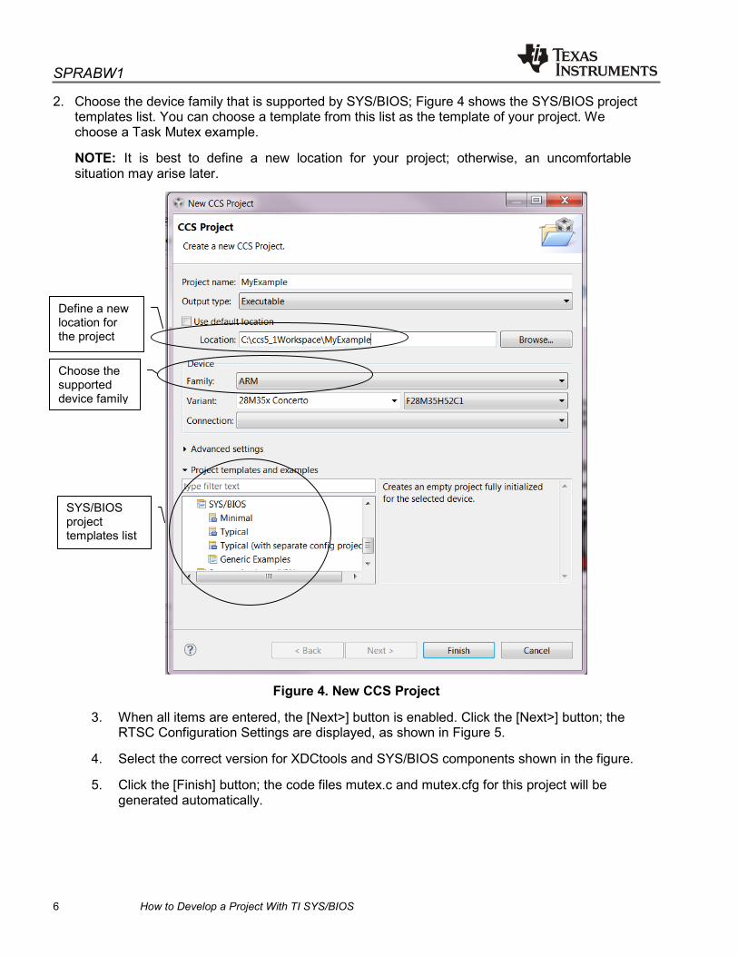
2. Choose the device family that is supported by SYS/BIOS; Figure 4 shows the SYS/BIOS project templates list. You can choose a template from this list as the template of your project. We choose a Task Mutex example.
NOTE: It is best to define a new location for your project; otherwise, an uncomfortable situation may arise later.
Figure 4. New CCS Project
3. When all items are entered, the [Next>] button is enabled. Click the [Next>] button; the RTSC Configuration Settings are displayed, as shown in Figure 5.
4. Select the correct version for XDCtools and SYS/BIOS components shown in the figure.
5. Click the [Finish] button; the code files mutex.c and mutex.cfg for this project will be generated automatically.
Choose the supported device family
Define a new location for the project
SYS/BIOS project templates list

SPRABW1
How to Develop a Project With TI SYS/BIOS 7
Figure 5. RTSC Configuration Settings for the SYS/BIOS Project
2.3 Link the Memory Map File for the Project
1. Now the project and the files should be listed in the Project Explorer. If you cannot see the Project Explorer, open it by clicking the tool menu of CCS ViewProject Explorer.
2. Right-click the project name, select Properties, and click General in the left block to open the General settings page (see Figure 6).
3. Choose the emulator connection method from the connection pulldown list.
4. Click the [Browse…] button to the right of the Linker command file: setting line and find the correct link file F28M35H52C1.cmd in the SYS/BIOS installation directory “C:\ti\bios_6_33_04_39\packages\ti\sysbios\examples\m3\include”.
5. After making these settings, click the [Apply] button and close the dialog box. Two more files, F28M35H52C1.cmd and F28M35H52C1.ccxml., are automatically added into the project files list. The F28M35H52C1.cmd file is the memory map file while the F28M35H52C1.ccxml file is the target configuration file.
Do nothing for this field
XDC 3.23.2.47
SYS/BIOS 6.33.4.39
SPRABW1
8 How to Develop a Project With TI SYS/BIOS
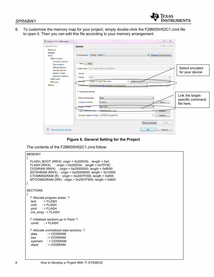
6. To customize the memory map for your project, simply double-click the F28M35H52C1.cmd file to open it. Then you can edit this file according to your memory arrangement.
Figure 6. General Setting for the Project
The contents of the F28M35H52C1.cmd follow:
MEMORY { FLASH_BOOT (RWX): origin = 0x200030, length = 0x4 FLASH (RWX) : origin = 0x200034, length = 0x7FF9C C03SRAM (RWX) : origin = 0x20000000, length = 0x8000 S07SHRAM (RWX) : origin = 0x20008000, length = 0x10000 CTOMMSGRAM (R) : origin = 0x2007F000, length = 0x800 MTOCMSGRAM (RW) : origin = 0x2007F800, length = 0x800 } SECTIONS { /* Allocate program areas: */ .text : > FLASH .cinit : > FLASH .pinit : > FLASH .init_array : > FLASH /* Initialized sections go in Flash */ .const : > FLASH /* Allocate uninitialized data sections: */ .data : > C03SRAM .bss : > C03SRAM .sysmem : > C03SRAM .stack : > C03SRAM
Select emulator for your device
Link the target-specific command file here.

SPRABW1
How to Develop a Project With TI SYS/BIOS 9
.cio : > C03SRAM .neardata : > C03SRAM .rodata : > C03SRAM .args : > C03SRAM } __STACK_TOP = __stack + 256; You can modify this file to customize the memory map for your device.
2.4 Build the Project
1. Open the Project Explorer window.
2. Right-click on the project name and select the Build Project command in the popup menu (see Figure 7).
The build message is displayed in the Console window (see Figure 8) and the detailed error and warning message is displayed in the Problems window (see Figure 9). If the building is done successfully, an .out program file is generated in the related folder.
Figure 7. CCS Project Explorer Window
The output file will be generated for running.

SPRABW1
10 How to Develop a Project With TI SYS/BIOS
Figure 8. CCS Console Window
Figure 9. CCS Problems Window
2.5 Debug the Project
The F28M35H52C1.ccxml file is a Target Configuration file. By double-clicking on the file name in the Project Explorer window, you can get the UI display for this file (see Figure 10). Before downloading the .out file to the device, you can test the connection of the emulator by clicking the [Test Connection] button.
Figure 10. ccxml File Edit Window
1. Connect one JTAG emulator with the PC.

SPRABW1
How to Develop a Project With TI SYS/BIOS 11
2. Open the Target Configuration window.
3. Right-click the ccxml file and choose Launch Selected Configuration to open the CCS Debug window.
4. Right-click the device core name and choose Connect Target from the popup menu to connect CCS with the emulator.
5. After the connection is made, download the .out program file to the target emulator, and then begin debugging the program.
Figure 11. CCS Debug Window
2.6 For More Reference
For more details about project building and debugging, refer the document TI SYS/BIOS Real-time Operating System v6.x User’s Guide (http://www.ti.com/lit/ug/spruex3m/spruex3m.pdf).
3 Use of the Basic Components for a SYS/BIOS Project
3.1 Use .cfg File to Configure the System
You can configure SYS/BIOS applications by modifying the *.cfg configuration file in the project. This file is written in the XDCscript language, which is a superset of JavaScript. CCS provides a graphical configuration editor called XGCONF. You can edit the file by using the XGCONF GUI interface. XGCONF is the default editor for files listed in the Project Explorer window. With the GUI editor, it is easier to view and configure the system components. You can choose the required components simply by clicking the icon, or you can configure the parameters by choosing the related options.
For details about how to configure the parameters for your project with the XDC GUI editor, refer the TI SYS/BIOS user guide (SPRUEX3M http://www.ti.com/lit/ug/spruex3m/spruex3m.pdf). If you are familiar with the JavaScript syntax, you can also edit the file with a text editor.
Download Program Connect Target Device core name

SPRABW1
12 How to Develop a Project With TI SYS/BIOS
Figure 12. XDCtools GUI Window (SYS/BIOS System Component Overview)
Figure 13. XDCtools GUI Window (SYS/BIOS Runtime Options)

SPRABW1
How to Develop a Project With TI SYS/BIOS 13
3.2 Entrance of the System
Like most systems, the entrance of the system is the function of main(). But the real entrance of SYS/BIOS OS is the caller of BIOS_start() at the end of main(). The initialization for the hardware of MCU, such as the GPIO port setting, peripheral interface configuration, must be done before BIOS_start() is called.
A typical example of main() follows:
Int main(Void) //Entrance of the system, the return type could be any type you want. { Error_Block eb; Task_Params taskParams; /* Call board init functions. */ Board_initGeneral(); Board_initGPIO(); Board_initUART(); /* Turn on user LED */ GPIO_write(Board_LED, Board_LED_ON); /* Create the task */ Error_init(&eb); Task_Params_init(&taskParams); taskParams.instance->name = "echo"; echo = Task_create(echoFxn, &taskParams, &eb); if (echo == NULL) { System_printf("Task was not created\n"); System_abort("Aborting...\n"); } /* Enable interrupts and start SYS/BIOS */ BIOS_start(); //Entrance of the SYS/BIOS return (0); }
To ensure the project can be built successfully, generally four head files must be included in your file. These head files are:
• <xdc/std.h>
• <xdc/runtime/System.h>
• <xdc/cfg/global.h>
• <ti/sysbios/BIOS.h>

SPRABW1
14 How to Develop a Project With TI SYS/BIOS
3.3 Dynamically or Statically Create the Task
The task is basically a thread unit in the SYS/BIOS system. You can put your desired action, which is not related with to? the interrupt, into a task. Sixteen priorities (0 through 15) were defined for the task. Because task 0 is used by the default system idle task, you can define the priority of your task from 1 to 15. The task with a priority of 0 has the lowest priority in the tasks schedule. If you want a task to be initially inactive, set its priority to -1. Such tasks are not scheduled to run until their priority is increased at runtime.
The tasks could be created dynamically or statically. Certainly, a task must be created once dynamically or statically within a project.
If you will use tasks in your project, you must include the head file of <ti/sysbios/knl/Task.h> in your code file.
3.3.1 Dynamically Creating the Task
Dynamically creating the task means the tasks are created in the .c code file. The task is created when the program calls the calling function in which the task code is created.
A typical example of creating the task dynamically follows:
Task_Handle taskHandle; Task_Params taskParams; Error_Block eb; Task_Params_init(&taskParams); taskParams.stackSize = 640; //define the stack size for the task taskParams.priority = 2; //define the priority of the task taskParams.instance->name = "Serial"; Error_init(&eb); taskHandle = Task_create(SerialMain, &taskParams, &eb); if (taskHandle == NULL) { System_printf("Task_create() failed!\n"); BIOS_exit(0); }
3.3.2 Statically Creating the Task
Statically creating the task means the tasks are created in the .cfg file. Once you add a task instance in the .cfg file, the task is created when the main() is run.
As described in Section 3.1, you can edit the .cfg file by the GUI tool or script text editor.
Open the Outline window and double-click the Task icon; the GUI of the Task Thread Management is displayed (see Figure 14). Tasks could be added or removed in the GUI. Also, the parameters such as Function entry, Priority, Stack size, and so forth for the task could be defined visually in the editor boxes. When you modify the value of the settings in the GUI window, the script source code is automatically generated in the source window of the .cfg file (see Figure 15).

SPRABW1
How to Develop a Project With TI SYS/BIOS 15
Figure 14. XDCtools GUI Window (Task Thread Management)
Figure 15. XDCtools GUI Window (Script Source Code for Task)
Once the task has been created statically, it is not necessary to dynamically add creation code in the .c file.
Script source code is generated automatically for task creation.
Double-click to open the management window.

SPRABW1
16 How to Develop a Project With TI SYS/BIOS
Statically creating the task is a good method because you could view the list of all of the tasks in your project in the Task Thread Management XDC GUI window. But if the task would not be lively during the system running period, it should be created dynamically.
For more detailed introduction about task thread, refer to the TI SYS/BIOS v6.35 Real-time Operating System User’s Guide (SPRUEX3M http://www.ti.com/lit/ug/spruex3m/spruex3m.pdf).
3.4 Usage of the Semaphores
Semaphore is one of the synchronization modules in the TI SYS/BIOS system. Semaphores are often used to coordinate access to a shared resource among a set of competing tasks. Semaphore objects can be declared as either counting or binary semaphores. For more details about semaphores, refer to the TI SYS/BIOS v6.35 Real-time Operating System User’s Guide (SPRUEX3M) (http://www.ti.com/lit/ug/spruex3m/spruex3m.pdf).
The head file <ti/sysbios/knl/Semaphore.h> must be included in your code file if you intend to use semaphores to do synchronization between the competing tasks.
Two often-used functions for the semaphores are:
Bool Semaphore_pend(Semaphore_Handle sem, UInt timeout);
Void Semaphore_post(Semaphore_Handle sem);
You could call Semaphore_pend(semHandle,BIOS_WAIT_FOREVER) in a task thread to wait for the other task thread releasing the share resource by calling Semaphore_post(semHandle).
Open the Outline window and double-click the Semaphore icon; the GUI of the Semaphore Management is displayed (see Figure 16). Semaphores could be added or removed by simply click the [Add] or [Remove] button in the Semaphore Management interface. The type of semaphores and the other required settings could be set by clicking the selection box or input characters in the edit box. After a semaphore is added, the related script source code is also generated automatically (see Figure 17). Handle will be the first parameter of the Semaphore_pend() and Semaphore_post() functions.
Double-click to open the management window

SPRABW1
How to Develop a Project With TI SYS/BIOS 17
Figure 16. XDCtools GUI Window (Semaphore Management)
Figure 17. XDCtools GUI Window (Script Source Code for Semaphore)
3.5 Use of the Mailboxes
3.5.1 Introduction About the Mailboxes
Mailboxes are used to pass buffers from one task to another task in the system. The mailbox module copies the buffer to fixed-size internal buffers. The size and number of these buffers are specified when a mailbox instance is created. All buffers sent and received with a same mailbox instance must be of the same size.
3.5.2 Use Mailboxes in Your Project
To use mailboxes in the project, you must ensure the mailbox component has been selected in the System Overview window (see Figure 18). Once the mailbox is added into your configuration (see Figure19), the related script code is added in the source code window. On the other hand, the head file <ti/sysbios/knl/Mailbox.h> must be included in your code file.
var Mailbox = xdc.useModule('ti.sysbios.knl.Mailbox'); //this script code adds the mailbox module into the project.
Figure 18. Selection of Synchronization Modules
Script source code of semaphore settings
This icon means the component is selected.

SPRABW1
18 How to Develop a Project With TI SYS/BIOS
Figure 19. XDCtools GUI Window (Mailbox Module Settings)
Open the Outline window and double-click the Mailbox icon, the GUI of the Semaphore Management is displayed (see Figure 20). Mailboxes can be added or removed by simply clicking the [Add] or [Remove] button. Normally, it is necessary to define only the Handle name, the size, and the number parameters for a mailbox. However, the size of the mailbox must be same as the size of the buffer which you will operate with this mailbox.
Figure 20. XDCtools GUI Window (Mailbox Instance Settings)
3.5.3 Often-used SYS/BIOS API Function for Mailbox
Two often-used functions for mailbox are:
This size must be the same as the size of the buf parameter in the Mailbox_pend() and Mailbox_post().

SPRABW1
How to Develop a Project With TI SYS/BIOS 19
Bool Mailbox_pend(Mailbox_Handle handle, Ptr buf, UInt timeout); Bool Mailbox_post(Mailbox_Handle handle, Ptr buf, UInt timeout);
Mailbox_pend() is used to read a buffer from a mailbox. If no buffer is available (that is, the mailbox is empty) and the time-out parameter is WAIT_FOREVER, Mailbox_pend() blocks.
Mailbox_post() is used to post a buffer to the mailbox. If no buffer slots are available (that is, the mailbox is full) and the time-out parameter is WAIT_FOREVER, Mailbox_post() blocks.
3.6 Use of the Hwi Tasks
3.6.1 Introduction to the Hwi
The Hwi is a special type of target- and device-specific task. Hwis are used to manage hardware interrupts, and they must be applied in response to external asynchronous events. For a detailed introduction, refer Section 3.3 in the TI SYS/BIOS v6.33 Real-time Operating System User’s Guide (SPRUEX3M) (http://www.ti.com/lit/ug/spruex3m/spruex3m.pdf).
3.6.2 Add Hwi Module in Your Project
To use Hwi tasks, the target-specific hardware interrupts module must be added into the configuration of the project. We use Cortex-M3 core as the example. Figure 21 shows the module settings. If you are not familiar with the configuration, try to keep the default values of most options.

SPRABW1
20 How to Develop a Project With TI SYS/BIOS
Figure 21. XDCtools GUI Window (Hardware Interrupt Module Settings)
The following script code is automatically added into the source of the .cfg file after the “Add M3-specific Hardware Interrupt to my configuration” checkbox is selected.
var ti_sysbios_family_arm_m3_Hwi = xdc.useModule('ti.sysbios.family.arm.m3.Hwi');
3.6.3 An Hwi Instance Example Based on Concerto™ F28M35x
We use the IPC3 interrupt as the example to introduce how to configure the Hwi task for it.
Open the Outline window and double-click the Hwi icon, the GUI of the M3 Hardware Interrupts – Instance Settings is displayed (see Figure 22). Hwis can be added or removed by simply clicking the [Add] or [Remove] button. The “ISR function” processes the respond for the interrupt. For the Interrupt number and Interrupt priority settings, we must refer the data sheet and the Reference Manual about the device.

SPRABW1
How to Develop a Project With TI SYS/BIOS 21
Figure 22. XDCtools GUI Window (Hardware Interrupt Instance Settings)
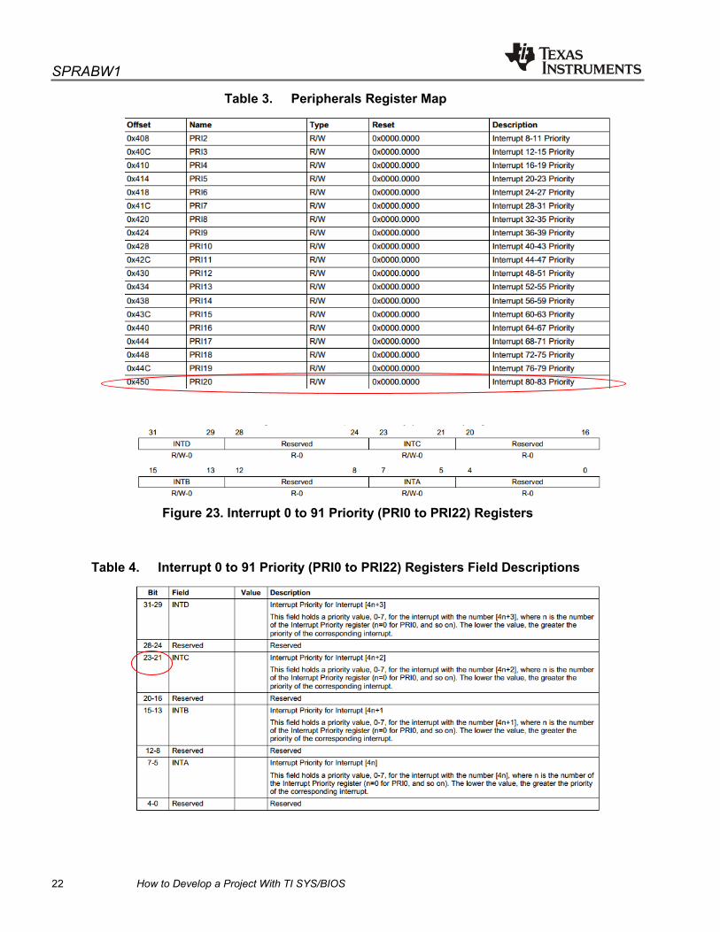
Table 2 is an interrupts table taken from SPRS742H (http://www.ti.com/lit/ds/symlink/f28m35h52c.pdf). In this table, we see that CTOMIPC3 has a vector number of 98 and an interrupt number of 82. The vector number 98 is the interrupt number 98 which was entered in the XDCtool shown as Figure 22.
Table 2. Interrupts from NVIC to Cortex-M3
In SPRUH22B (http://www.ti.com/lit/ug/spruh22f/spruh22f.pdf), the priority register for interrupt 82 has been assigned to PRI20. See Table 3 for the definition. Then, we determined that bit 22 in Table 4, which is bit 6 of the PRI20 register, is used for the interrupt priority setting for interrupt 82. To set the priority of interrupt 82, the value of PRI20 should be set to hex value 0x20 (equal to decimal value 32). This value is the value 32, which should be entered into the “Interrupt priority” edit box of the Instance Settings GUI (see Figure 22).
SPRABW1
22 How to Develop a Project With TI SYS/BIOS
Table 3. Peripherals Register Map
Figure 23. Interrupt 0 to 91 Priority (PRI0 to PRI22) Registers
Table 4. Interrupt 0 to 91 Priority (PRI0 to PRI22) Registers Field Descriptions

SPRABW1
How to Develop a Project With TI SYS/BIOS 23
To use the Hwi tasks in your project, the head file <ti/sysbios/family/arm/m3/Hwi.h> must be included in your .c file. The other hardware-related head files such as hw_ints.h, which is in the “MWare\inc”, should also be included in your .c files.
In this example, the ISR function body is as follows:
void IPC_rxIntHndlr(void) { // stat IPC_cntxt.rx_isr ++; // mark CM3 is busy IPC_setBusyIndn(); // post semaphore to task CM3_Post_HCT_RX_Semaphore(); // Acknowledge IPC INT3 from C28 to ACK HWREG(MTOCIPC_BASE + IPC_O_CTOMIPCACK) |= IPC_CTOMIPCACK_IPC3; }
To make a Hwi task work normally, it is very important to set the correct configuration for the task.
References
1. TI-RTOS 1.21 Getting Started Guide (SPRUHD3G) 2. TI SYS/BIOS v6.35 Real-time Operating System User’s Guide (SPRUEX3M) 3. TI SYS/BIOS Real-time Operating System v6.x User’s Guide (SPRUEX3J) 4. Concerto Microcontrollers (SPRS742H) 5. Concerto F28M35x Technical Reference Manual (SPRUH22B)

IMPORTANT NOTICETexas Instruments Incorporated and its subsidiaries (TI) reserve the right to make corrections, enhancements, improvements and otherchanges to its semiconductor products and services per JESD46, latest issue, and to discontinue any product or service per JESD48, latestissue. Buyers should obtain the latest relevant information before placing orders and should verify that such information is current andcomplete. All semiconductor products (also referred to herein as “components”) are sold subject to TI’s terms and conditions of salesupplied at the time of order acknowledgment.TI warrants performance of its components to the specifications applicable at the time of sale, in accordance with the warranty in TI’s termsand conditions of sale of semiconductor products. Testing and other quality control techniques are used to the extent TI deems necessaryto support this warranty. Except where mandated by applicable law, testing of all parameters of each component is not necessarilyperformed.TI assumes no liability for applications assistance or the design of Buyers’ products. Buyers are responsible for their products andapplications using TI components. To minimize the risks associated with Buyers’ products and applications, Buyers should provideadequate design and operating safeguards.TI does not warrant or represent that any license, either express or implied, is granted under any patent right, copyright, mask work right, orother intellectual property right relating to any combination, machine, or process in which TI components or services are used. Informationpublished by TI regarding third-party products or services does not constitute a license to use such products or services or a warranty orendorsement thereof. Use of such information may require a license from a third party under the patents or other intellectual property of thethird party, or a license from TI under the patents or other intellectual property of TI.Reproduction of significant portions of TI information in TI data books or data sheets is permissible only if reproduction is without alterationand is accompanied by all associated warranties, conditions, limitations, and notices. TI is not responsible or liable for such altereddocumentation. Information of third parties may be subject to additional restrictions.Resale of TI components or services with statements different from or beyond the parameters stated by TI for that component or servicevoids all express and any implied warranties for the associated TI component or service and is an unfair and deceptive business practice.TI is not responsible or liable for any such statements.Buyer acknowledges and agrees that it is solely responsible for compliance with all legal, regulatory and safety-related requirementsconcerning its products, and any use of TI components in its applications, notwithstanding any applications-related information or supportthat may be provided by TI. Buyer represents and agrees that it has all the necessary expertise to create and implement safeguards whichanticipate dangerous consequences of failures, monitor failures and their consequences, lessen the likelihood of failures that might causeharm and take appropriate remedial actions. Buyer will fully indemnify TI and its representatives against any damages arising out of the useof any TI components in safety-critical applications.In some cases, TI components may be promoted specifically to facilitate safety-related applications. With such components, TI’s goal is tohelp enable customers to design and create their own end-product solutions that meet applicable functional safety standards andrequirements. Nonetheless, such components are subject to these terms.No TI components are authorized for use in FDA Class III (or similar life-critical medical equipment) unless authorized officers of the partieshave executed a special agreement specifically governing such use.Only those TI components which TI has specifically designated as military grade or “enhanced plastic” are designed and intended for use inmilitary/aerospace applications or environments. Buyer acknowledges and agrees that any military or aerospace use of TI componentswhich have not been so designated is solely at the Buyer's risk, and that Buyer is solely responsible for compliance with all legal andregulatory requirements in connection with such use.TI has specifically designated certain components as meeting ISO/TS16949 requirements, mainly for automotive use. In any case of use ofnon-designated products, TI will not be responsible for any failure to meet ISO/TS16949.Products ApplicationsAudio www.ti.com/audio Automotive and Transportation www.ti.com/automotiveAmplifiers amplifier.ti.com Communications and Telecom www.ti.com/communicationsData Converters dataconverter.ti.com Computers and Peripherals www.ti.com/computersDLP® Products www.dlp.com Consumer Electronics www.ti.com/consumer-appsDSP dsp.ti.com Energy and Lighting www.ti.com/energyClocks and Timers www.ti.com/clocks Industrial www.ti.com/industrialInterface interface.ti.com Medical www.ti.com/medicalLogic logic.ti.com Security www.ti.com/securityPower Mgmt power.ti.com Space, Avionics and Defense www.ti.com/space-avionics-defenseMicrocontrollers microcontroller.ti.com Video and Imaging www.ti.com/videoRFID www.ti-rfid.comOMAP Applications Processors www.ti.com/omap TI E2E Community e2e.ti.comWireless Connectivity www.ti.com/wirelessconnectivity
Mailing Address: Texas Instruments, Post Office Box 655303, Dallas, Texas 75265Copyright © 2014, Texas Instruments Incorporated