Embed Size (px)
Citation preview
website: www.jdsu.com/test
COMMUNICATIONS TeST & MeASUreMeNT SOlUTIONS
JD72OC-SeriesCable and Antenna Analyzers
Key Benefits • Intuitiveuserinterfacewithtouchscreenandindoor/outdoordisplaymodes
• Dualdisplayandzoomzonesforfasteranalysis
• RFportprotectionupto40dBm(10W)
• ControlsRFandopticalpowersensors
Key Features• FavoriteandQuick Savekeysfor
easierandfastertesting• Broadbandcalibrationformaximumtesttime
• 7.5hoursofcontinuousbatteryoperation
Applications• Traceoverlay• Zoomzones• Dualdisplay• AlternatesweepinDTF
Key Measurements• Reflection—VSWR/returnloss• DTF—VSWR/returnloss• 1-Portcableloss• Smithchart• 1-Portphase• RFpowermeter(optional)• Opticalpowermeter(optional)
Themajorityofproblemsinmobilenetworksoccurinthebasestation’sinfrastruc-ture,consistingoftheantennasystem,cables,andconnectors.Toproperlyserviceandinstallcellsitesrequiressuitabletestequipment.TheJDSUJD720C-SeriesCableandAntennaAnalyzersareoptimaltestsolutionsforcharacterizingcell-siteinfrastructurebecauseoftheirhandhelddesign,easeofuse,andrichfunctionality.TheJD720C-seriesanalyzersofferthemeasurementfunctionsnecessarytoaccu-ratelyverifyasite’stransmissionlineandantennasystemfromsignalreflections(voltagestandingwaveratio[VSWR]orreturnloss)toRForopticaltransmissionpower.Inaddition,theJD720C-seriesanalyzersaccuratelymeasurethedistancetofault(DTF)forproperidentificationofitslocation.The instrument’s touch-panel operation and 7-inch-wide thin-film transistor(TFT)colordisplayforeasiermeasurementsanddisplay.Also,itsapplication-spe-cificsoftwareforeasiermeasurementcomparisonandanalysisandforgeneratingprofessionalreports.
2
JD72OC SerieS Cable anD antenna analyzerS
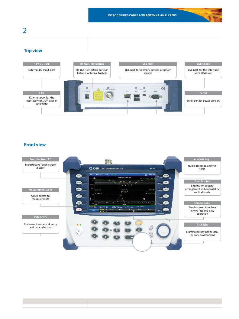
Quick access to measurements
Measurement Keys
Quick access to analysis tools
Analysis Keys
Convenient numerical entry and data selection
Data Entry
Touch-screen interface allows fast and easy
operation
Screen Menu
TransflectiveTouch-screen display
Transflective LCD
Convenient display arrangement in horizontal or
vertical mode
Dual Display
Illuminated key panel ideal for dark environment
Backlight
USB port for the interface with JDViewer
USB Client
RF Out/Reflection port for Cable & Antenna Analysis
RF Out / Reflection
USB port for memory devices or power sensors
USB Host
Serial port for power sensors
Serial
External DC input port
15V DC Port
Ethernet port for the interface with JDViewer or
JDRemote
LAN
Top view
Front view
3
JD72OC SerieS Cable anD antenna analyzerS
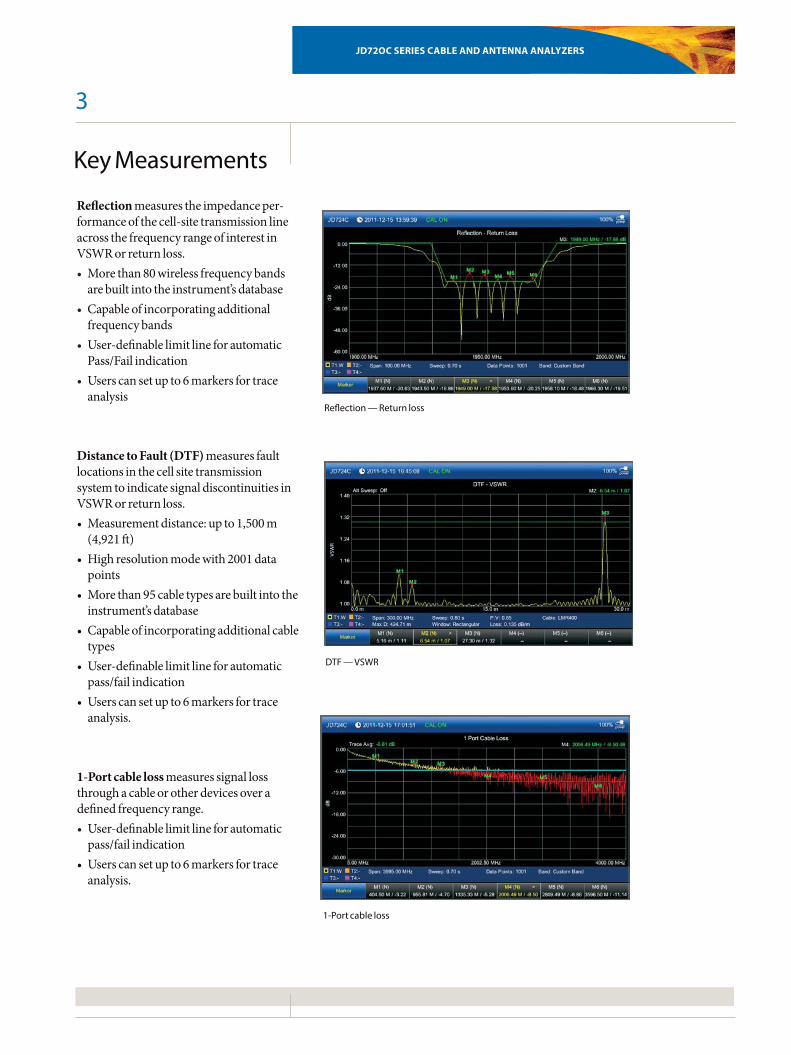
Key Measurements
Reflection — Return loss
DTF — VSWR
1-Port cable loss
Reflectionmeasurestheimpedanceper-formanceofthecell-sitetransmissionlineacrossthefrequencyrangeofinterestinVSWRorreturnloss.• Morethan80wirelessfrequencybandsarebuiltintotheinstrument’sdatabase
• Capableofincorporatingadditionalfrequencybands
• User-definablelimitlineforautomaticPass/Failindication
• Userscansetupto6markersfortraceanalysis
Distance to Fault (DTF)measuresfaultlocationsinthecellsitetransmissionsystemtoindicatesignaldiscontinuitiesinVSWRorreturnloss.• Measurementdistance:upto1,500m(4,921ft)
• Highresolutionmodewith2001datapoints
• Morethan95cabletypesarebuiltintotheinstrument’sdatabase
• Capableofincorporatingadditionalcabletypes
• User-definablelimitlineforautomaticpass/failindication
• Userscansetupto6markersfortraceanalysis.
1-Port cable lossmeasuressignallossthroughacableorotherdevicesoveradefinedfrequencyrange.• User-definablelimitlineforautomaticpass/failindication
• Userscansetupto6markersfortraceanalysis.
4
JD72OC SerieS Cable anD antenna analyzerS
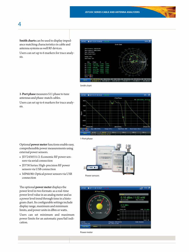
Smith chartscanbeusedtodisplayimped-ancematchingcharacteristicsincableandantennasystemsaswellRFdevices.Userscansetupto6markersfortraceanaly-sis.
1-Port phasemeasuresS11phasetotuneantennasandphase-matchcables.Userscansetupto6markersfortraceanaly-sis.
Optionalpower meterfunctionsenableeasy,comprehensiblepowermeasurementsusingexternalpowersensors.• JD72450551/2:EconomicRFpowersen-sorsviaserialconnection
• JD730Series:High-precisionRFpowersensorsviaUSBconnection
• MP60/80:OpticalpowersensorsviaUSBconnection
Theoptionalpower meterdisplaysthepowerlevelintwoformats:asareal-timepowerlevelvalueinananalogmeterandasapowerleveltrendthroughtimeinahisto-gramchart.Itsconfigurablesettingsincludedisplayrange,maximumandminimumlimits,andpowerunitsindBmorwatts.Users can set minimum and maximumpowerlimitsforanautomaticpass/failindi-cation.
1-Port phase
Power sensors
Power meter
Smith chart
5
JD72OC SerieS Cable anD antenna analyzerS
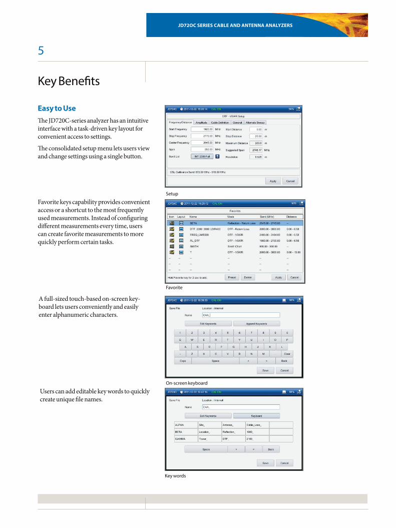
Setup
Favorite
On-screen keyboard
Key Benefits
Easy to UseTheJD720C-seriesanalyzerhasanintuitiveinterfacewithatask-drivenkeylayoutforconvenientaccesstosettings.
Theconsolidatedsetupmenuletsusersviewandchangesettingsusingasinglebutton.
Favoritekeyscapabilityprovidesconvenientaccessorashortcuttothemostfrequentlyusedmeasurements.Insteadofconfiguringdifferentmeasurementseverytime,userscancreatefavoritemeasurementstomorequicklyperformcertaintasks.
Afull-sizedtouch-basedon-screenkey-boardletsusersconvenientlyandeasilyenteralphanumericcharacters.
Userscanaddeditablekeywordstoquicklycreateuniquefilenames.
Key words
6
JD72OC SerieS Cable anD antenna analyzerS
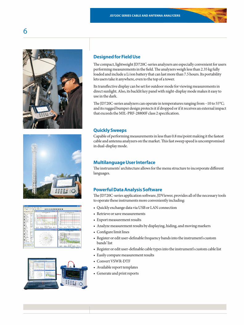
Designed for Field UseThecompact,lightweightJD720C-seriesanalyzersareespeciallyconvenientforusersperformingmeasurementsinthefield.Theanalyzersweighlessthan2.35kgfullyloadedandincludeaLiionbatterythatcanlastmorethan7.5hours.Itsportabilityletsuserstakeitanywhere,eventothetopofatower.
Itstransflectivedisplaycanbesetforoutdoormodeforviewingmeasurementsindirectsunlight.Also,itsbacklitkeypanelwithnight-displaymodemakesiteasytouseinthedark.
TheJD720C-seriesanalyzerscanoperateintemperaturesrangingfrom–10to55°C;anditsruggedbumperdesignprotectsitifdroppedorifitreceivesanexternalimpactthatexceedstheMIL-PRF-28800Fclass2specification.
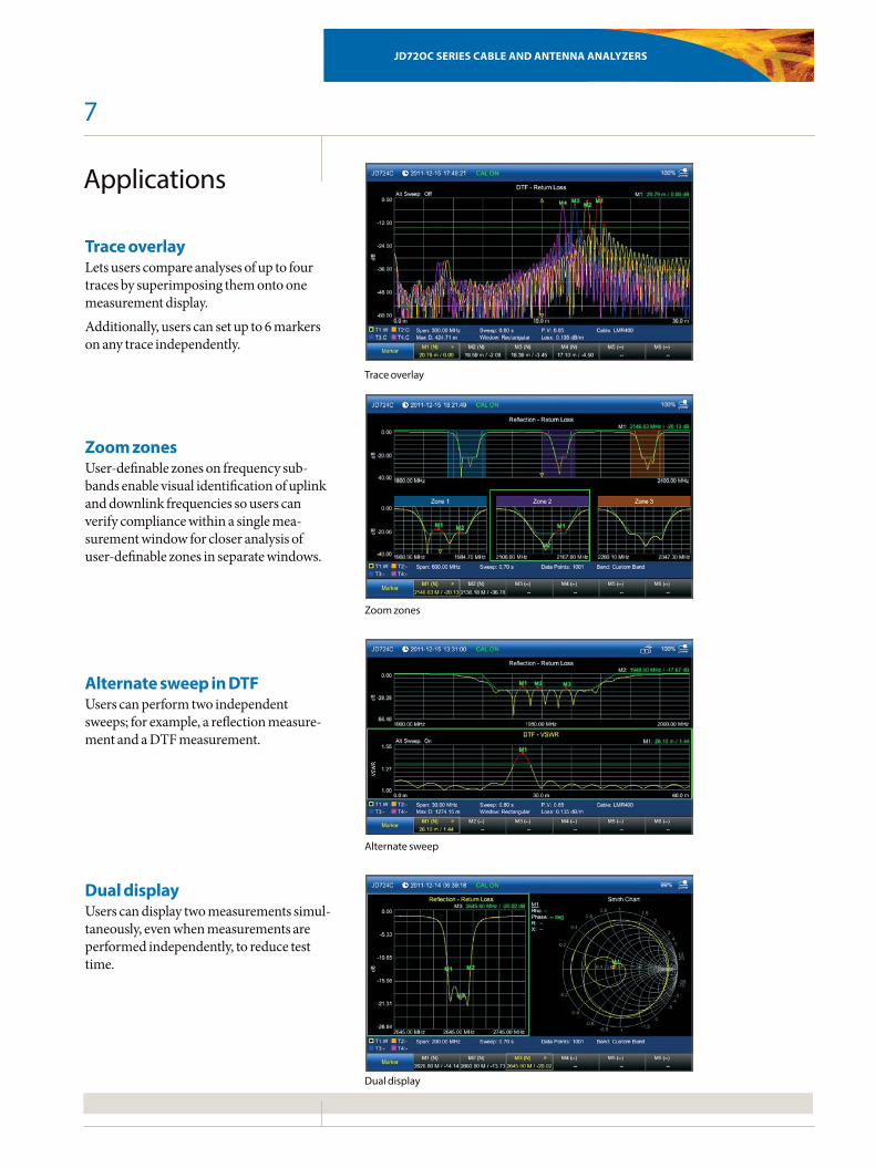
Quickly SweepsCapableofperformingmeasurementsinlessthan0.8ms/pointmakingitthefastestcableandantennaanalyzersonthemarket.Thisfastsweepspeedisuncompromisedindual-displaymode.
Multilanguage User InterfaceTheinstruments’architectureallowsforthemenustructuretoincorporatedifferentlanguages.
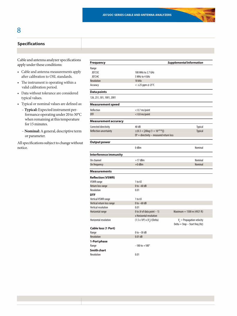
Powerful Data Analysis SoftwareTheJD720C-seriesapplicationsoftware,JDViewer,providesallofthenecessarytoolstooperatetheseinstrumentsmoreconvenientlyincluding:
• QuicklyexchangedataviaUSBorLANconnection• Retrieveorsavemeasurements• Exportmeasurementresults• Analyzemeasurementresultsbydisplaying,hiding,andmovingmarkers• Configurelimitlines• Registeroredituser-definablefrequencybandsintotheinstrument’scustombands’list
• Registeroredituser-definablecabletypesintotheinstrument’scustomcablelist• Easilycomparemeasurementresults• ConvertVSWR-DTF• Availablereporttemplates• Generateandprintreports
7
JD72OC SerieS Cable anD antenna analyzerS
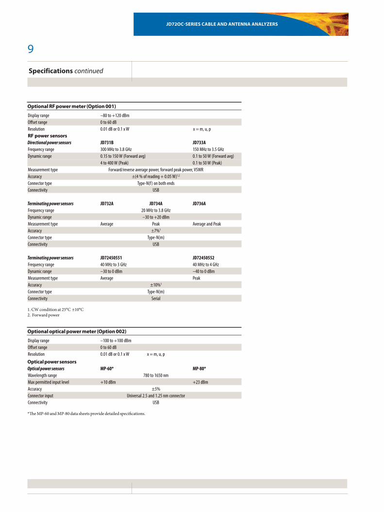
Trace overlayLetsuserscompareanalysesofuptofourtracesbysuperimposingthemontoonemeasurementdisplay.Additionally,userscansetupto6markersonanytraceindependently.
Zoom zonesUser-definablezonesonfrequencysub-bandsenablevisualidentificationofuplinkanddownlinkfrequenciessouserscanverifycompliancewithinasinglemea-surementwindowforcloseranalysisofuser-definablezonesinseparatewindows.
Alternate sweep in DTFUserscanperformtwoindependentsweeps;forexample,areflectionmeasure-mentandaDTFmeasurement.
Dual displayUserscandisplaytwomeasurementssimul-taneously,evenwhenmeasurementsareperformedindependently,toreducetesttime.
Applications
Trace overlay
Zoom zones
Alternate sweep
Dual display
8
JD72OC-SerieS Cable anD antenna analyzerS
Specifications
Frequency Supplemental Information
Range JD723C 100 MHz to 2.7 GHz JD724C 5 MHz to 4 GHzResolution 10 kHzAccuracy < ±25 ppm @ 25°C
Data points
126, 251, 501, 1001, 2001
Measurement speed
Reflection < 0.7 ms/point DTF < 0.8 ms/point
Measurement accuracy
Corrected directivity 40 dB TypicalReflection uncertainty ±(0.3 + |20log (1 + 10-EP/20)|) Typical EP = directivity – measured return loss
Output power
0 dBm Nominal
Interference immunity
On channel +17 dBm NominalOn frequency +0 dBm Nominal
Measurements
Reflection (VSWR) VSWR range 1 to 65 Return loss range 0 to –60 dB Resolution 0.01
DTF Vertical VSWR range 1 to 65 Vertical return loss range 0 to –60 dB Vertical resolution 0.01 Horizontal range 0 to (# of data point – 1) Maximum = 1500 m (4921 ft) x Horizontal resolution Horizontal resolution (1.5 x 10⁸) x (Vp)/(Delta) Vp = Propagation velocity Delta = Stop – Start freq (Hz) Cable loss (1 Port) Range 0 to –30 dB Resolution 0.01 dB
1-Port phase Range –180 to +180°
Smith chart Resolution 0.01
Cableandantennaanalyzerspecificationsapplyundertheseconditions:
• CableandantennameasurementsapplyaftercalibrationtoOSLstandards.
• Theinstrumentisoperatingwithinavalidcalibrationperiod.
• Datawithouttoleranceareconsideredtypicalvalues.
• Typicalornominalvaluesaredefinedas:–Typical:Expectedinstrumentper-formanceoperatingunder20to30°Cwhenremainingatthistemperaturefor15minutes.
–Nominal:Ageneral,descriptivetermorparameter.
Allspecificationssubjecttochangewithoutnotice.
9
JD72OC-SerieS Cable anD antenna analyzerS
Specifications continued
Optional RF power meter (Option 001)
Display range –80 to +120 dBm Offset range 0 to 60 dB Resolution 0.01 dB or 0.1 x W x = m, u, p RF power sensors Directional power sensors JD731B JD733AFrequency range 300 MHz to 3.8 GHz 150 MHz to 3.5 GHzDynamic range 0.15 to 150 W (Forward avg) 0.1 to 50 W (Forward avg) 4 to 400 W (Peak) 0.1 to 50 W (Peak)Measurement type Forward/reverse average power, forward peak power, VSWRAccuracy ±(4 % of reading + 0.05 W)1,2
Connector type Type-N(f) on both endsConnectivity USB Terminating power sensors JD732A JD734A JD736AFrequency range 20 MHz to 3.8 GHzDynamic range –30 to +20 dBmMeasurement type Average Peak Average and PeakAccuracy ±7%1
Connector type Type-N(m)Connectivity USB Terminating power sensors JD72450551 JD72450552Frequency range 40 MHz to 3 GHz 40 MHz to 4 GHzDynamic range –30 to 0 dBm –40 to 0 dBmMeasurement type Average PeakAccuracy ±10%1
Connector type Type-N(m)Connectivity Serial
1.CWconditionat25°C±10°C2.Forwardpower
Optional optical power meter (Option 002)
Display range –100 to +100 dBm Offset range 0 to 60 dB Resolution 0.01 dB or 0.1 x W x = m, u, p
Optical power sensors Optical power sensors MP-60* MP-80*Wavelength range 780 to 1650 nmMax permitted input level +10 dBm +23 dBmAccuracy ±5%Connector input Universal 2.5 and 1.25 nm connectorConnectivity USB
*TheMP-60andMP-80datasheetsprovidedetailedspecifications.
10
JD72OC-SerieS Cable anD antenna analyzerS
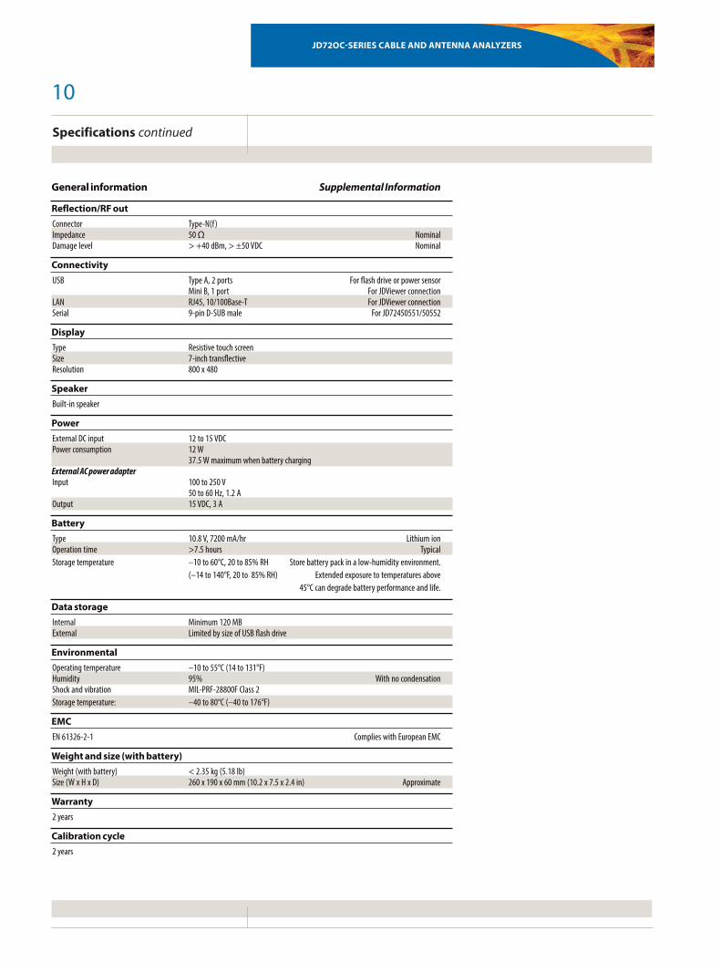
General information Supplemental Information
Reflection/RF out Connector Type-N(f) Impedance 50 Ω NominalDamage level > +40 dBm, > ±50 VDC Nominal
Connectivity USB Type A, 2 ports For flash drive or power sensor Mini B, 1 port For JDViewer connectionLAN RJ45, 10/100Base-T For JDViewer connectionSerial 9-pin D-SUB male For JD72450551/50552
Display Type Resistive touch screen Size 7-inch transflective Resolution 800 x 480
Speaker Built-in speaker
Power External DC input 12 to 15 VDC Power consumption 12 W 37.5 W maximum when battery charging External AC power adapter Input 100 to 250 V 50 to 60 Hz, 1.2 A Output 15 VDC, 3 A
Battery Type 10.8 V, 7200 mA/hr Lithium ionOperation time >7.5 hours TypicalStorage temperature –10 to 60°C, 20 to 85% RH Store battery pack in a low-humidity environment. (–14 to 140°F, 20 to 85% RH) Extended exposure to temperatures above 45°C can degrade battery performance and life.
Data storage Internal Minimum 120 MB External Limited by size of USB flash drive
Environmental Operating temperature –10 to 55°C (14 to 131°F) Humidity 95% With no condensationShock and vibration MIL-PRF-28800F Class 2Storage temperature: –40 to 80°C (–40 to 176°F)
EMC EN 61326-2-1 Complies with European EMC
Weight and size (with battery) Weight (with battery) < 2.35 kg (5.18 lb) Size (W x H x D) 260 x 190 x 60 mm (10.2 x 7.5 x 2.4 in) Approximate
Warranty 2 years
Calibration cycle 2 years
Specifications continued
11
JD72OC-SerieS Cable anD antenna analyzerS
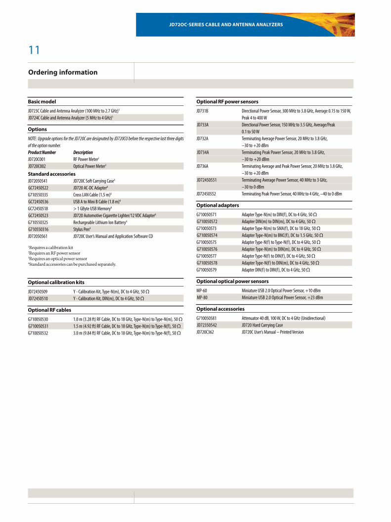
Ordering information
Basic model
JD723C Cable and Antenna Analyzer (100 MHz to 2.7 GHz)1
JD724C Cable and Antenna Analyzer (5 MHz to 4 GHz)1
Options
NOTE: Upgrade options for the JD720C are designated by JD720CU before the respective last three digits of the option number.Product Number DescriptionJD720C001 RF Power Meter2
JD720C002 Optical Power Meter3
Standard accessoriesJD72050541 JD720C Soft Carrying Case4
GC72450522 JD720 AC-DC Adapter4
G710550335 Cross LAN Cable (1.5 m)4
GC72450536 USB A to Mini B Cable (1.8 m)4
GC72450518 > 1 GByte USB Memory4
GC72450523 JD720 Automotive Cigarette Lighter/12 VDC Adapter4
G710550325 Rechargeable Lithium Ion Battery4
G710550316 Stylus Pen4
JD72050561 JD720C User’s Manual and Application Software CD
1Requiresacalibrationkit2RequiresanRFpowersensor3Requiresanopticalpowersensor4Standardaccessoriescanbepurchasedseparately.
Optional calibration kits
JD72450509 Y - Calibration Kit, Type-N(m), DC to 4 GHz, 50 ΩJD72450510 Y - Calibration Kit, DIN(m), DC to 4 GHz, 50 Ω
Optional RF cables
G710050530 1.0 m (3.28 ft) RF Cable, DC to 18 GHz, Type-N(m) to Type-N(m), 50 ΩG710050531 1.5 m (4.92 ft) RF Cable, DC to 18 GHz, Type-N(m) to Type-N(f), 50 ΩG710050532 3.0 m (9.84 ft) RF Cable, DC to 18 GHz, Type-N(m) to Type-N(f), 50 Ω
Optional RF power sensors
JD731B Directional Power Sensor, 300 MHz to 3.8 GHz, Average 0.15 to 150 W, Peak 4 to 400 WJD733A Directional Power Sensor, 150 MHz to 3.5 GHz, Average/Peak 0.1 to 50 WJD732A Terminating Average Power Sensor, 20 MHz to 3.8 GHz, –30 to +20 dBmJD734A Terminating Peak Power Sensor, 20 MHz to 3.8 GHz, –30 to +20 dBmJD736A Terminating Average and Peak Power Sensor, 20 MHz to 3.8 GHz, –30 to +20 dBmJD72450551 Terminating Average Power Sensor, 40 MHz to 3 GHz, –30 to 0 dBmJD72450552 Terminating Peak Power Sensor, 40 MHz to 4 GHz, –40 to 0 dBm
Optional adapters
G710050571 Adapter Type-N(m) to DIN(f), DC to 4 GHz, 50 ΩG710050572 Adapter DIN(m) to DIN(m), DC to 4 GHz, 50 ΩG710050573 Adapter Type-N(m) to SMA(f), DC to 18 GHz, 50 ΩG710050574 Adapter Type-N(m) to BNC(f), DC to 1.5 GHz, 50 ΩG710050575 Adapter Type-N(f) to Type-N(f), DC to 4 GHz, 50 ΩG710050576 Adapter Type-N(m) to DIN(m), DC to 4 GHz, 50 ΩG710050577 Adapter Type-N(f) to DIN(f), DC to 4 GHz, 50 ΩG710050578 Adapter Type-N(f) to DIN(m), DC to 4 GHz, 50 ΩG710050579 Adapter DIN(f) to DIN(f), DC to 4 GHz, 50 Ω
Optional optical power sensors
MP-60 Miniature USB 2.0 Optical Power Sensor, +10 dBmMP-80 Miniature USB 2.0 Optical Power Sensor, +23 dBm
Optional accessories
G710050581 Attenuator 40 dB, 100 W, DC to 4 GHz (Unidirectional)JD72350542 JD720 Hard Carrying CaseJD720C362 JD720C User’s Manual – Printed Version

JD72OC-SerieS Cable anD antenna analyzerS
Product specifications and descriptions in this document subject to change without notice. © 2012 JDS Uniphase Corporation 30173185 001 1012 JD720C.DS.CPO.TM.AE October 2012
test & Measurement regional Sales
nOrtH aMeriCatoll free: 1 855 ASK-JDSU 1 855 275-5378
latin aMeriCatel: +1 954 688 5660fAX: +1 954 345 4668
aSia PaCiFiCtel: +852 2892 0990fAX: +852 2892 0770
eMeatel: +49 7121 86 2222fAX: +49 7121 86 1222
www.jdsu.com/test